installation and customization - - apc usa · evaluating data center design and construction. ......
TRANSCRIPT

Installation and Customization
NetShelter™ CX Enclosures
990-3594C-001Publication Date: August 2015

Schneider Electric Legal DisclaimerThe information presented in this manual is not warranted by Schneider Electric to be authoritative, error free,
or complete. This publication is not meant to be a substitute for a detailed operational and site specific
development plan. Therefore, Schneider Electric assumes no liability for damages, violations of codes,
improper installation, system failures, or any other problems that could arise based on the use of this
Publication.
The information contained in this Publication is provided as is and has been prepared solely for the purpose of
evaluating data center design and construction. This Publication has been compiled in good faith by Schneider
Electric. However, no representation is made or warranty given, either express or implied, as to the
completeness or accuracy of the information this Publication contains.
IN NO EVENT SHALL SCHNEIDER ELECTRIC, OR ANY PARENT, AFFILIATE OR SUBSIDIARY COMPANY
OF SCHNEIDER ELECTRIC OR THEIR RESPECTIVE OFFICERS, DIRECTORS, OR EMPLOYEES BE
LIABLE FOR ANY DIRECT, INDIRECT, CONSEQUENTIAL, PUNITIVE, SPECIAL, OR INCIDENTAL
DAMAGES (INCLUDING, WITHOUT LIMITATION, DAMAGES FOR LOSS OF BUSINESS, CONTRACT,
REVENUE, DATA, INFORMATION, OR BUSINESS INTERRUPTION) RESULTING FROM, ARISING OUT,
OR IN CONNECTION WITH THE USE OF, OR INABILITY TO USE THIS PUBLICATION OR THE CONTENT,
EVEN IF SCHNEIDER ELECTRIC HAS BEEN EXPRESSLY ADVISED OF THE POSSIBILITY OF SUCH
DAMAGES. SCHNEIDER ELECTRIC RESERVES THE RIGHT TO MAKE CHANGES OR UPDATES WITH
RESPECT TO OR IN THE CONTENT OF THE PUBLICATION OR THE FORMAT THEREOF AT ANY TIME
WITHOUT NOTICE.
Copyright, intellectual, and all other proprietary rights in the content (including but not limited to software, audio,
video, text, and photographs) rests with Schneider Electric or its licensors. All rights in the content not expressly
granted herein are reserved. No rights of any kind are licensed or assigned or shall otherwise pass to persons
accessing this information.
This Publication shall not be for resale in whole or in part.

Table of Contents
General Information ...............................................................................................1
Important Safety Information . . . . . . . . . . . . . . . . . . . . . . . . . . . . . . . . . . . . . . . . . . . . . . .1
About This Manual . . . . . . . . . . . . . . . . . . . . . . . . . . . . . . . . . . . . . . . . . . . . . . . . . . . . . . .1
Related Documents . . . . . . . . . . . . . . . . . . . . . . . . . . . . . . . . . . . . . . . . . . . . . . . . . . . . . .1
User Comments . . . . . . . . . . . . . . . . . . . . . . . . . . . . . . . . . . . . . . . . . . . . . . . . . . . . . . . . .1
Safety.....................................................................................................................2
Important Safety Instructions . . . . . . . . . . . . . . . . . . . . . . . . . . . . . . . . . . . . . . . . . . . . . . .2
SAVE THESE INSTRUCTIONS . . . . . . . . . . . . . . . . . . . . . . . . . . . . . . . . . . . . . .2
Product Overview...................................................................................................3Description . . . . . . . . . . . . . . . . . . . . . . . . . . . . . . . . . . . . . . . . . . . . . . . . . . . . . .3
NetShelter CX Enclosures . . . . . . . . . . . . . . . . . . . . . . . . . . . . . . . . . . . . . . . . . .3
Inventory. . . . . . . . . . . . . . . . . . . . . . . . . . . . . . . . . . . . . . . . . . . . . . . . . . . . . . . . . . . . . . .4
Enclosure components . . . . . . . . . . . . . . . . . . . . . . . . . . . . . . . . . . . . . . . . . . . .4
Tools required (not provided) . . . . . . . . . . . . . . . . . . . . . . . . . . . . . . . . . . . . . . . .5
Moving the enclosure . . . . . . . . . . . . . . . . . . . . . . . . . . . . . . . . . . . . . . . . . . . . . . . . . . . . .5
Configuration..........................................................................................................6
Blanking panels . . . . . . . . . . . . . . . . . . . . . . . . . . . . . . . . . . . . . . . . . . . . . . . . . . . . . . . . .6
Front doors and Side Panels . . . . . . . . . . . . . . . . . . . . . . . . . . . . . . . . . . . . . . . . . . . . . . .6
Hinges . . . . . . . . . . . . . . . . . . . . . . . . . . . . . . . . . . . . . . . . . . . . . . . . . . . . . . . . .6
Installation..............................................................................................................8
Installation and Setup . . . . . . . . . . . . . . . . . . . . . . . . . . . . . . . . . . . . . . . . . . . . . . . . . . . . .8
Level the enclosure . . . . . . . . . . . . . . . . . . . . . . . . . . . . . . . . . . . . . . . . . . . . . . .8
Rack stabilization options . . . . . . . . . . . . . . . . . . . . . . . . . . . . . . . . . . . . . . . . . . .9
Fan Module Removal and Installation . . . . . . . . . . . . . . . . . . . . . . . . . . . . . . . . . . . . . . .10
Unlock the fan module . . . . . . . . . . . . . . . . . . . . . . . . . . . . . . . . . . . . . . . . . . . .10
Lock the fan module . . . . . . . . . . . . . . . . . . . . . . . . . . . . . . . . . . . . . . . . . . . . . .10
Open the fan modules . . . . . . . . . . . . . . . . . . . . . . . . . . . . . . . . . . . . . . . . . . . .10
Remove the fan modules . . . . . . . . . . . . . . . . . . . . . . . . . . . . . . . . . . . . . . . . . .11
Install the fan module . . . . . . . . . . . . . . . . . . . . . . . . . . . . . . . . . . . . . . . . . . . . .11
NetShelter CX Enclosure Installation and Customization i
Rack PDU . . . . . . . . . . . . . . . . . . . . . . . . . . . . . . . . . . . . . . . . . . . . . . . . . . . . . . . . . . . . .12
AP9567 - NEMA . . . . . . . . . . . . . . . . . . . . . . . . . . . . . . . . . . . . . . . . . . . . . . . . .12
AP9568 - IEC . . . . . . . . . . . . . . . . . . . . . . . . . . . . . . . . . . . . . . . . . . . . . . . . . . .12
Specifications . . . . . . . . . . . . . . . . . . . . . . . . . . . . . . . . . . . . . . . . . . . . . . . . . . .12
Electrical . . . . . . . . . . . . . . . . . . . . . . . . . . . . . . . . . . . . . . . . . . . . . . . . . . . . . . .12
Connect the Rack PDU . . . . . . . . . . . . . . . . . . . . . . . . . . . . . . . . . . . . . . . . . . . .12
Vertical Mounting Flanges . . . . . . . . . . . . . . . . . . . . . . . . . . . . . . . . . . . . . . . . . . . . . . . .13
Adjusting the vertical mounting flanges on the side braces . . . . . . . . . . . . . . . .13
Rack Mount Equipment Installation . . . . . . . . . . . . . . . . . . . . . . . . . . . . . . . . . . . . . . . . .14
One U-space on the vertical mounting flange . . . . . . . . . . . . . . . . . . . . . . . . . . .14
Cage nut installation . . . . . . . . . . . . . . . . . . . . . . . . . . . . . . . . . . . . . . . . . . . . . .14
Cage nut removal . . . . . . . . . . . . . . . . . . . . . . . . . . . . . . . . . . . . . . . . . . . . . . . .14
Equipment Planning Guidelines . . . . . . . . . . . . . . . . . . . . . . . . . . . . . . . . . . . . . . . . . . . .15
Internal Enclosure Dimensions . . . . . . . . . . . . . . . . . . . . . . . . . . . . . . . . . . . . . . . . . . . . .16
Cable Management. . . . . . . . . . . . . . . . . . . . . . . . . . . . . . . . . . . . . . . . . . . . . . . . . . . . . .17
Rear cable access port . . . . . . . . . . . . . . . . . . . . . . . . . . . . . . . . . . . . . . . . . . . .17
Vertical 0U accessory channels . . . . . . . . . . . . . . . . . . . . . . . . . . . . . . . . . . . . .17
Cable management options for the enclosures . . . . . . . . . . . . . . . . . . . . . . . . .18
Air Circulation . . . . . . . . . . . . . . . . . . . . . . . . . . . . . . . . . . . . . . . . . . . . . . . . . . . . . . . . . .21
Enclosure placement . . . . . . . . . . . . . . . . . . . . . . . . . . . . . . . . . . . . . . . . . . . . .21
Specifications ...................................................................................................... 22
18, 24, 38U Enclosures. . . . . . . . . . . . . . . . . . . . . . . . . . . . . . . . . . . . . . . . . . . . . . . . . . .22
Two-Year Factory Warranty ................................................................................ 23Terms of warranty . . . . . . . . . . . . . . . . . . . . . . . . . . . . . . . . . . . . . . . . . . . . . . . .23
Non-transferable warranty . . . . . . . . . . . . . . . . . . . . . . . . . . . . . . . . . . . . . . . . .23
Exclusions . . . . . . . . . . . . . . . . . . . . . . . . . . . . . . . . . . . . . . . . . . . . . . . . . . . . . .23
Warranty claims . . . . . . . . . . . . . . . . . . . . . . . . . . . . . . . . . . . . . . . . . . . . . . . . .23
NetShelter CX Enclosure Installation and Customizationii

General Information
Important Safety InformationRead the instructions carefully and become familiar with the enclosure before trying to install or maintain it. The following special messages may appear throughout this manual or on the enclosure to warn of potential hazards or to call attention to information that clarifies or simplifies a procedure.
The addition of this symbol to a Danger or Warning safety label indicates that an electrical hazard exists which will result in personal injury if the instructions are not followed.
This is the safety alert symbol. It is used to alert you to potential personal injury hazards. Obey all safety messages that follow this symbol to avoid possible injury or death.
About This ManualThis manual is intended for users of the specified Schneider Electric equipment. It contains important safety warnings and instructions and provides detailed information for proper use of the equipment.
Related DocumentsDownload technical publications and other technical information or look for updates to your manual at our website at www.schneider-electric.com.
User CommentsContact www.schneider-electric.com/support. We welcome your comments about this document.
DANGERDANGER indicates an imminently hazardous situation which, if not avoided, will result in death or serious injury.
WARNINGWARNING indicates a potentially hazardous situation which, if not avoided, can result in death or serious injury.
CAUTIONCAUTION indicates a potentially hazardous situation which, if not avoided, can result in minor or moderate injury.
CAUTIONCAUTION (without alert symbol) indicates a potentially hazardous situation which, if not avoided, can result in equipment damage.
NOTICENOTICE addresses practices not related to physical injury including certain environmental hazards, potential damage or loss of data.
1 NetShelter CX Enclosure Installation and Customization

Safety
Important Safety Instructions
SAVE THESE INSTRUCTIONS
This manual contains important instructions that must be followed during installation, operation, and maintenance of the equipment.
Use caution when moving an empty enclosure on its casters. The enclosure may be unstable when pushed or pulled from the side. Push the enclosure from the front or back when moving it on its casters. For extra stability, load 158 kg (350 lbs) of equipment into the bottom of the enclosure before moving it on its casters.
DANGERHAZARD OF ELECTRIC SHOCK, EXPLOSION, OR ARC FLASH
• Follow all local and national codes when installing the Rack PDU.
• Connect the Rack PDU to the UPS, if installed, or to a single-outlet dedicated circuit protected by a circuit breaker or fuse with the same current rating as the Rack PDU.
• Power off the UPS or Mains Supply before connecting the Rack PDU.
• The plug or inlet serves as the disconnect for the Rack PDU. Make sure the utility power outlet for the Rack PDU will be close to the Rack PDU and readily accessible.
Failure to follow these instructions will result in death or serious injury.
WARNINGTIP HAZARD
• Stabilize the enclosure before installing the components.
• Do not extend components on sliding rails out from the enclosure until you have installed three or more pieces of similar equipment, or the stabilizer plate or bolt-down brackets are installed.
• Do not extend more than one component from the enclosure at a time.
• Load the heaviest components first, and place them toward the bottom of the enclosure to prevent the enclosure from becoming top-heavy.
Failure to follow these instructions can result in death, serious injury, or equipment damage.
CAUTIONWEIGHT AND LEVERAGE HAZARD
• Doors and side panels are heavy. Removal or installation requires two people.• Fan modules are heavy. Two people are recommended when removing the fan modules
from the enclosures.Failure to follow these instructions can result in injury.
NOTICETo ensure adequate air movement, place the side of the enclosure no closer than six to eight inches to the wall.
NetShelter CX Enclosure Installation and Customization2

Product OverviewDescription
NetShelter CX enclosures are specialized enclosures with integrated cooling, noise dampening, and power distribution for server and network applications in office environments. The enclosures provide storage for industry-standard (EIA-310), 19 in. rack-mount hardware, which includes servers, voice, data, networking, internetworking, and Schneider Electric power protection equipment.
NetShelter CX Enclosures
†One U= 44.45 mm (1.75 in.). See “One U-space on the vertical mounting flange” on page 14.
Model Voltage and Connector Type
Rack Mounting
Height
Rack Mounting
Widthmm (in.)
Rack Mounting
Depthmm (in.)
External Enclosure
Heightmm (in.)
External Enclosure
Widthmm (in.)
External Enclosure
Depthmm (in.)
AR4018AAR4018X429AR4018X431AR4018X432
100-120VNEMA 5-15P
18 U† 482 (19)
880(34.6)
1015 (40)
750 (29.53)
1130 (44.5)AR4018IA
AR4018IX429AR4018IX431AR4018IX432
200-230VIEC-320 C14
AR4024AAR4024X429AR4024X431AR4024X432
100-120VNEMA 5-15P
24 U482 (19)
880(34.6)
1275(50.2)
750 (29.53)
1130 (44.5)AR4024IA
AR4024IX429AR4024IX431AR4024IX432
200-230VIEC-320 C14
AR4038AAR4038X429AR4038X431AR4038X432
100-120VNEMA 5-15P
38 U482 (19)
880(34.6)
1950 (76.8)
750 (29.53)
1130(44.5)AR4038IA
AR4038IX429AR4038IX431AR4038IX432
200-230VIEC-320 C14
3 NetShelter CX Enclosure Installation and Customization

NetShelter CX Enclosure Installation and Customization4
InventoryEnclosure components
ns27
28a
† The leveling feet, door keys, and rack PDU power cord (not shown) are not installed and can be found packed inside the enclosure.
Top cable access port Leveling foot (6)†
Fan module (3) Vertical mounting flange (4)
Side access panel (2) Front door (2)
Key (2)† Airflow opening
Vertical OU accessory channel (4)
Fan module power supply (3)
Bottom cable access port Basic Rack PDU (1)
Caster (4)
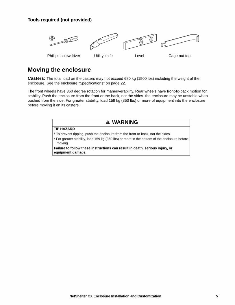
Tools required (not provided)
Moving the enclosureCasters: The total load on the casters may not exceed 680 kg (1500 lbs) including the weight of the enclosure. See the enclosure “Specifications” on page 22.
The front wheels have 360 degree rotation for maneuverability. Rear wheels have front-to-back motion for stability. Push the enclosure from the front or the back, not the sides. the enclosure may be unstable when pushed from the side. For greater stability, load 159 kg (350 lbs) or more of equipment into the enclosure before moving it on its casters.
Phillips screwdriver Utility knife Level Cage nut tool
WARNINGTIP HAZARD
• To prevent tipping, push the enclosure from the front or back, not the sides.
• For greater stability, load 159 kg (350 lbs) or more in the bottom of the enclosure before moving.
Failure to follow these instructions can result in death, serious injury, or equipment damage.
5 NetShelter CX Enclosure Installation and Customization

Configuration
Before installing the enclosure, plan the location and space needed to install equipment, and plan the ergonomics of keyboards and video monitors. Improper airflow could damage installed components.
Blanking panelsUse blanking panels to close up large open spaces in the CX but not to completely seal the rack. The NetShelter CX works best when air can travel not just through the equipment vents, but also above and below any equipment that generates thermal energy.
Schneider Electric offers modular, plastic Airflow Management Blanking Panels that snap into place without tools (AR8136BLK).
Front doors and Side PanelsThe front doors and side panels may be opened or removed to access the interior. Locking side panels offer additional security and assist with proper airflow within the enclosure. The locking side panel does not ship locked. To avoid personal injury or damage to the enclosure, one person should support the door or side panel while another person removes the door or side panel from its frame.
Hinges
Installation Slide the hinge on the door or side panel into the front of the mounting plate attached to the inside of the enclosure.
Using finger pressure, press the hinge onto the mounting plate. The latch will secure with an audible click.
CAUTIONWEIGHT AND LEVERAGE HAZARD
Doors and side panels are heavy. Removal or installation requires two people.Failure to follow these instructions can result in injury.
CLICK!
ns1969a
NetShelter CX Enclosure Installation and Customization6
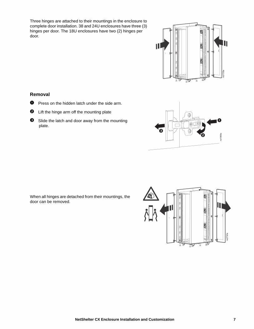
Three hinges are attached to their mountings in the enclosure to complete door installation. 38 and 24U enclosures have three (3) hinges per door. The 18U enclosures have two (2) hinges per door.
Removal
Press on the hidden latch under the side arm.
Lift the hinge arm off the mounting plate
Slide the latch and door away from the mounting plate.
When all hinges are detached from their mountings, the door can be removed.
ns1968a
7 NetShelter CX Enclosure Installation and Customization
Installation
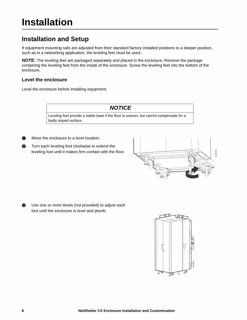
Installation and SetupIf equipment mounting rails are adjusted from their standard factory installed positions to a deeper position, such as in a networking application, the leveling feet must be used.
NOTE: The leveling feet are packaged separately and placed in the enclosure. Remove the package containing the leveling feet from the inside of the enclosure. Screw the leveling feet into the bottom of the enclosure.
Level the enclosure
Level the enclosure before installing equipment.
Move the enclosure to a level location.
Turn each leveling foot clockwise to extend the
leveling foot until it makes firm contact with the floor.
Use one or more levels (not provided) to adjust each
foot until the enclosure is level and plumb.
NOTICELeveling feet provide a stable base if the floor is uneven, but cannot compensate for a badly sloped surface.
ns2
727a
ns27
36a
NetShelter CX Enclosure Installation and Customization8
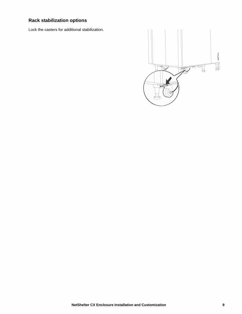
Rack stabilization options
Lock the casters for additional stabilization.
9 NetShelter CX Enclosure Installation and Customization

Fan Module Removal and Installation
Unlock the fan module
Open the right hand side access panel. Unscrew the thumbscrew on the right side of the fan module to unlock the fan module so it can be opened.
Lock the fan module
Open the right hand side access panel. Install the thumbscrew on the right side of the fan module to lock the fan module in place.
Open the fan modules
ns27
37a
The clips pull apart to release.
The module can then be swung open.To open all the fan modules, start at the bottom.
1. Swing the fan module out on its hinges.
2. Disconnect the fan module power supply lead from the fan module.
3. Open the bottom module Open the center module Open the top module
NetShelter CX Enclosure Installation and Customization10
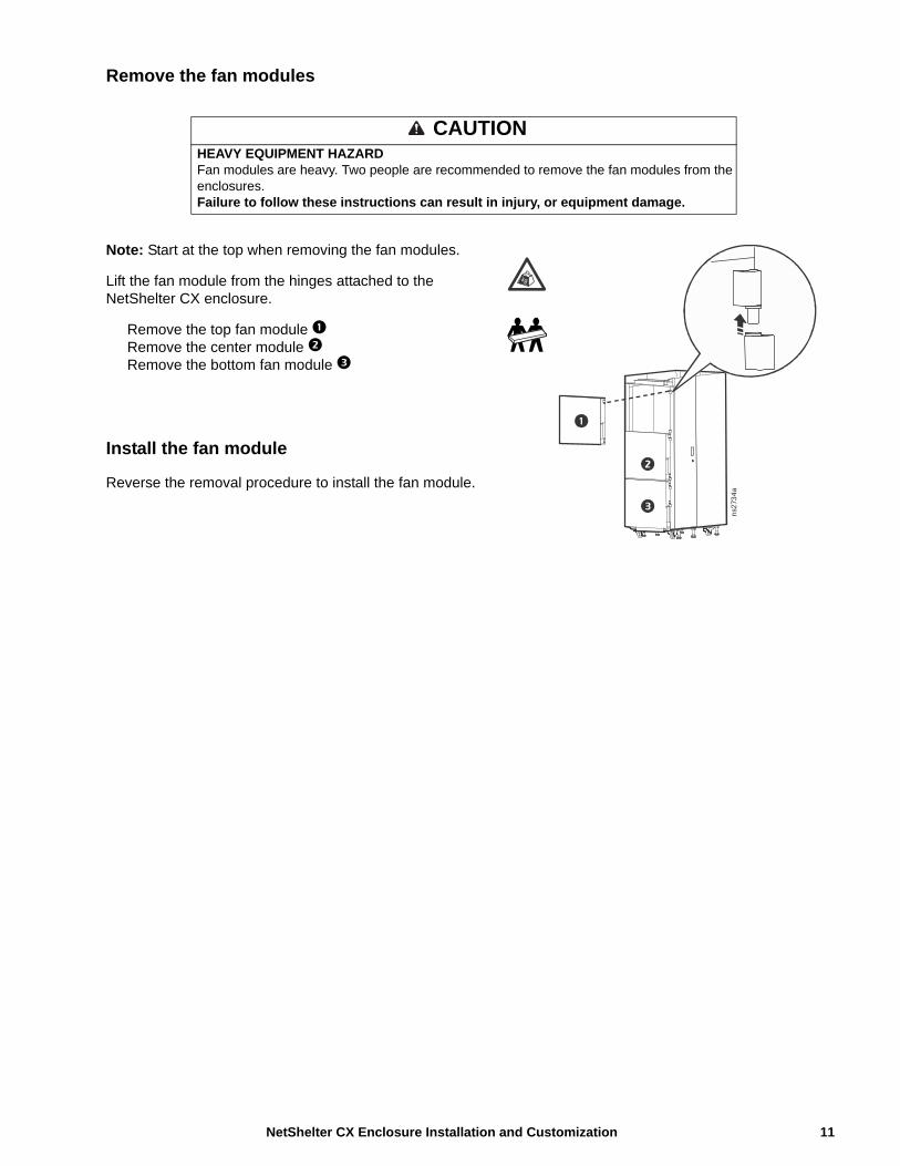
Remove the fan modules
Note: Start at the top when removing the fan modules.
Lift the fan module from the hinges attached to the NetShelter CX enclosure.
Remove the top fan module Remove the center module Remove the bottom fan module
Install the fan module
Reverse the removal procedure to install the fan module.
CAUTIONHEAVY EQUIPMENT HAZARDFan modules are heavy. Two people are recommended to remove the fan modules from the enclosures.Failure to follow these instructions can result in injury, or equipment damage.
ns2
734
a
11 NetShelter CX Enclosure Installation and Customization

Rack PDUThe NetShelter CX Enclosure is provided with one Basic Rack PDU. The Rack PDU distributes power to devices in the enclosure.
AP9567 - NEMAOutlets The Rack PDU has fourteen (14) NEMA 5015R outlets.
Power cord The 12 foot (3.66 meter) power cord terminates with a NEMA 5-15P plug.
AP9568 - IECOutlets The Rack PDU has fifteen (15) IEC-320-C13 outlets.
Power cord The 6.5 foot (1.98 meter) power cord terminates with a IEC-320-C14 plug.
Specifications
Electrical
Connect the Rack PDU
Connect the Rack PDU to the UPS when a UPS is installed in the enclosure or connect it to the nearest local Mains supply point.
AP9567 AP9568
Input connector NEMA 5-15P IEC-320-C14 inlet
Output connectors (14 ) NEMA 5-15R outlets (15 ) IEC-320-C13 outlets
Nominal input voltage 100-120 VAC 120 - 240 VAC
Acceptable input voltage ± 10 % of nominal voltage
Input frequency 50 / 60 Hz
DANGERHAZARD OF ELECTRIC SHOCK, EXPLOSION, OR ARC FLASH
• Follow all local and national codes when installing the Rack PDU.
• Never use extension cords with the Rack PDU.
• Connect the Rack PDU to the UPS, if installed, or to a single-outlet dedicated circuit protected by a circuit breaker or fuse with the same current rating as the Rack PDU.
• Power off the UPS or Mains Supply before connecting the Rack PDU.
• The plug or inlet serves as the disconnect for the Rack PDU. Make sure the utility power outlet for the Rack PDU will be close to the Rack PDU and readily accessible.
Failure to follow these instructions will result in death or serious injury.
NetShelter CX Enclosure Installation and Customization12
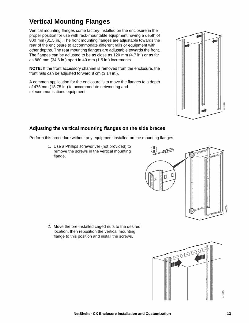
Vertical Mounting FlangesVertical mounting flanges come factory-installed on the enclosure in the proper position for use with rack-mountable equipment having a depth of 800 mm (31.5 in.). The front mounting flanges are adjustable towards the rear of the enclosure to accommodate different rails or equipment with other depths. The rear mounting flanges are adjustable towards the front. The flanges can be adjusted to be as close as 120 mm (4.7 in.) or as far as 880 mm (34.6 in.) apart in 40 mm (1.5 in.) increments.
NOTE: If the front accessory channel is removed from the enclosure, the front rails can be adjusted forward 8 cm (3.14 in.).
A common application for the enclosure is to move the flanges to a depth of 476 mm (18.75 in.) to accommodate networking and telecommunications equipment.
Adjusting the vertical mounting flanges on the side braces
Perform this procedure without any equipment installed on the mounting flanges.
1. Use a Phillips screwdriver (not provided) to remove the screws in the vertical mounting flange.
2. Move the pre-installed caged nuts to the desired location, then reposition the vertical mounting flange to this position and install the screws.
ns15
51a
ns1
552
a
ns15
53a
13 NetShelter CX Enclosure Installation and Customization
Rack Mount Equipment InstallationThis section provides information on how to install rack-mount equipment in the enclosure. The manufacturer’s instructions included with the equipment provide more detailed information.
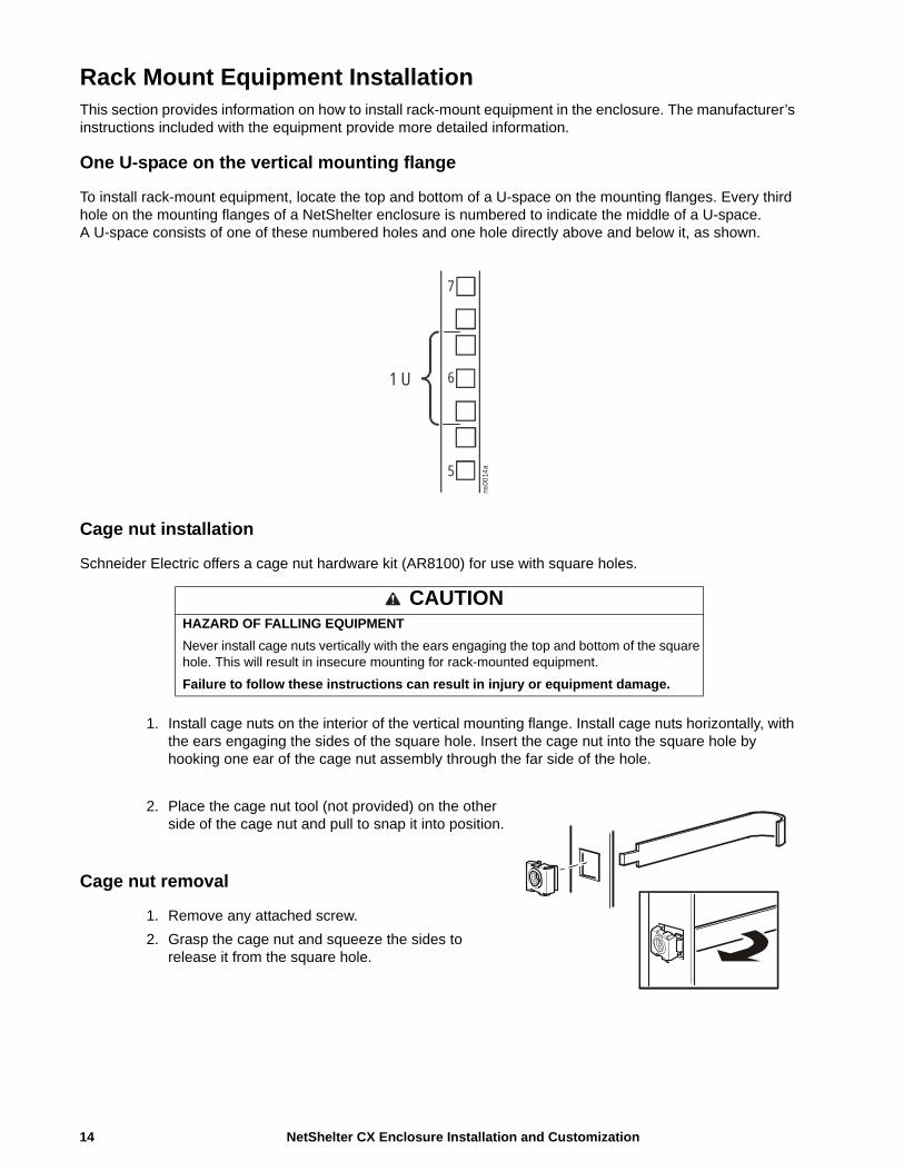
One U-space on the vertical mounting flange
To install rack-mount equipment, locate the top and bottom of a U-space on the mounting flanges. Every third hole on the mounting flanges of a NetShelter enclosure is numbered to indicate the middle of a U-space. A U-space consists of one of these numbered holes and one hole directly above and below it, as shown.
Cage nut installation
Schneider Electric offers a cage nut hardware kit (AR8100) for use with square holes.
1. Install cage nuts on the interior of the vertical mounting flange. Install cage nuts horizontally, with the ears engaging the sides of the square hole. Insert the cage nut into the square hole by hooking one ear of the cage nut assembly through the far side of the hole.
2. Place the cage nut tool (not provided) on the other side of the cage nut and pull to snap it into position.
Cage nut removal
1. Remove any attached screw.
2. Grasp the cage nut and squeeze the sides to release it from the square hole.
CAUTIONHAZARD OF FALLING EQUIPMENT
Never install cage nuts vertically with the ears engaging the top and bottom of the square hole. This will result in insecure mounting for rack-mounted equipment.
Failure to follow these instructions can result in injury or equipment damage.
1 U
7
6
5ns
0014
a
NetShelter CX Enclosure Installation and Customization14
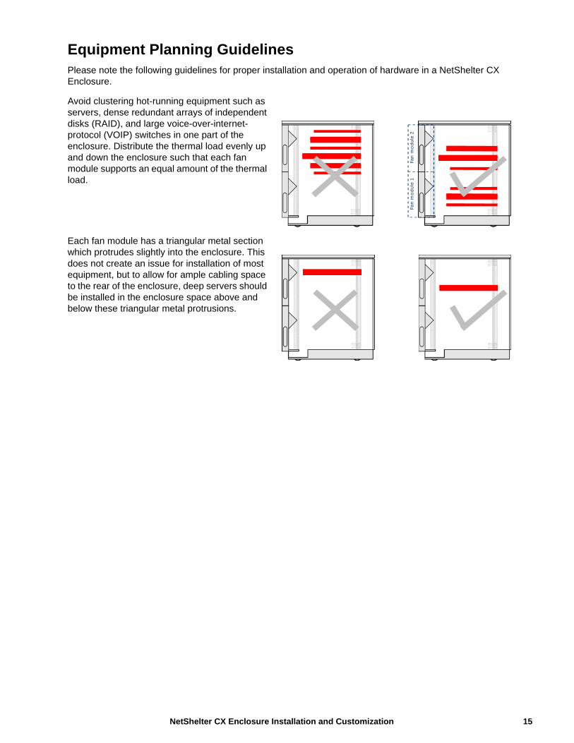
Equipment Planning GuidelinesPlease note the following guidelines for proper installation and operation of hardware in a NetShelter CX Enclosure.
Avoid clustering hot-running equipment such as servers, dense redundant arrays of independent disks (RAID), and large voice-over-internet-protocol (VOIP) switches in one part of the enclosure. Distribute the thermal load evenly up and down the enclosure such that each fan module supports an equal amount of the thermal load.
Each fan module has a triangular metal section which protrudes slightly into the enclosure. This does not create an issue for installation of most equipment, but to allow for ample cabling space to the rear of the enclosure, deep servers should be installed in the enclosure space above and below these triangular metal protrusions.
Fan
mod
ule
2Fa
n m
odul
e 1
15 NetShelter CX Enclosure Installation and Customization
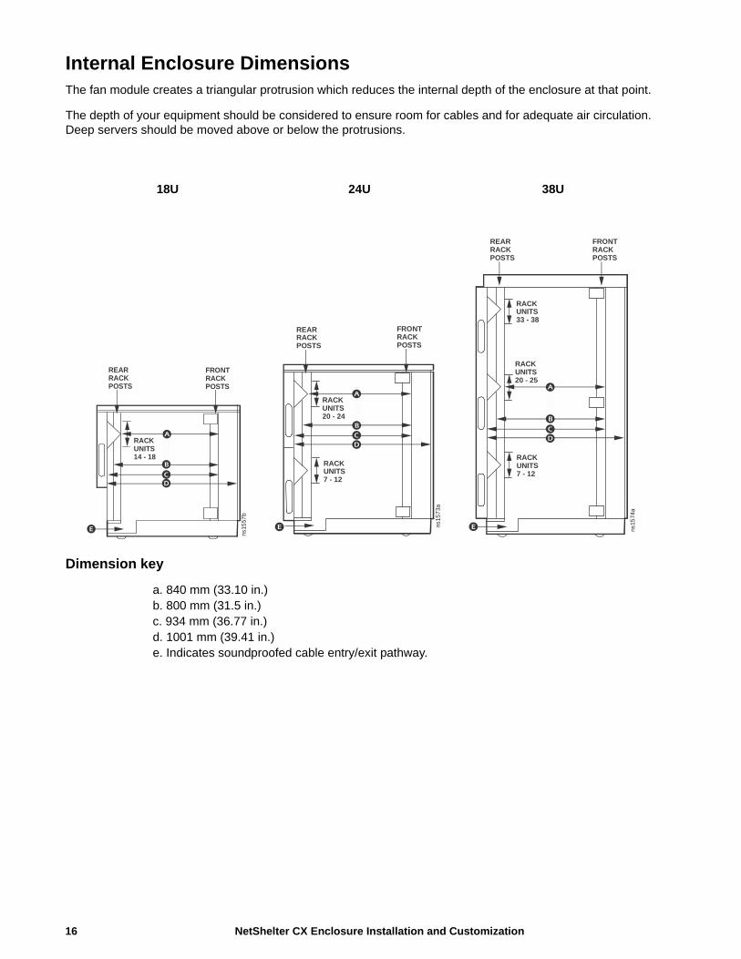
Internal Enclosure DimensionsThe fan module creates a triangular protrusion which reduces the internal depth of the enclosure at that point.
The depth of your equipment should be considered to ensure room for cables and for adequate air circulation. Deep servers should be moved above or below the protrusions.
Dimension key
a. 840 mm (33.10 in.)b. 800 mm (31.5 in.)c. 934 mm (36.77 in.)d. 1001 mm (39.41 in.)e. Indicates soundproofed cable entry/exit pathway.
18U 24U 38U
REARRACKPOSTS
FRONTRACKPOSTS
RACKUNITS14 - 18
ns15
57b
REARRACKPOSTS
FRONTRACKPOSTS
RACKUNITS20 - 24
RACKUNITS7 - 12
ns15
73a
REARRACKPOSTS
FRONTRACKPOSTS
RACKUNITS33 - 38
RACKUNITS20 - 25
RACKUNITS7 - 12
ns15
74a
NetShelter CX Enclosure Installation and Customization16
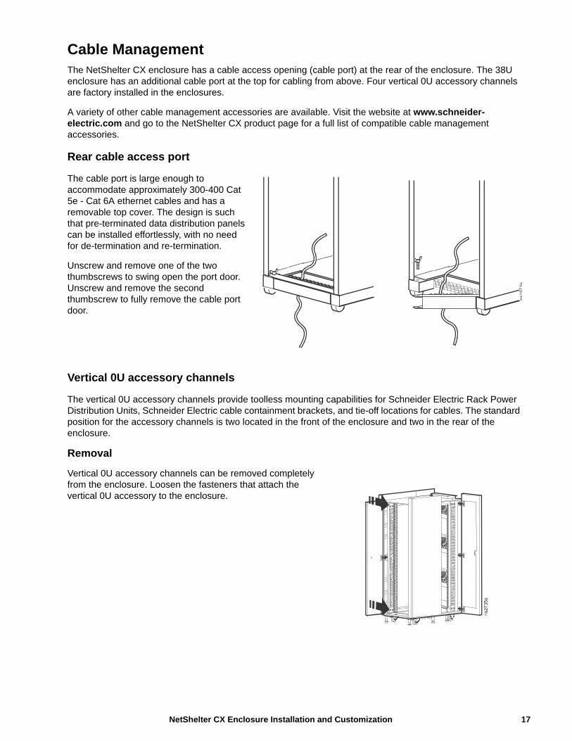
Cable ManagementThe NetShelter CX enclosure has a cable access opening (cable port) at the rear of the enclosure. The 38U enclosure has an additional cable port at the top for cabling from above. Four vertical 0U accessory channels are factory installed in the enclosures.
A variety of other cable management accessories are available. Visit the website at www.schneider-electric.com and go to the NetShelter CX product page for a full list of compatible cable management accessories.
Rear cable access port
The cable port is large enough to accommodate approximately 300-400 Cat 5e - Cat 6A ethernet cables and has a removable top cover. The design is such that pre-terminated data distribution panels can be installed effortlessly, with no need for de-termination and re-termination.
Unscrew and remove one of the two thumbscrews to swing open the port door. Unscrew and remove the second thumbscrew to fully remove the cable port door.
Vertical 0U accessory channels
The vertical 0U accessory channels provide toolless mounting capabilities for Schneider Electric Rack Power Distribution Units, Schneider Electric cable containment brackets, and tie-off locations for cables. The standard position for the accessory channels is two located in the front of the enclosure and two in the rear of the enclosure.
Removal
Vertical 0U accessory channels can be removed completely from the enclosure. Loosen the fasteners that attach the vertical 0U accessory to the enclosure.
ns1
970
a
17 NetShelter CX Enclosure Installation and Customization

Cable management options for the enclosures
Product SKU Description Figure
19 in. horizontal cable organizers
AR8602 (1U)
AR8600 (2U)
AR8601 (2U double sided)
AR8603A (2U high density)
Route patch cables horizontally at the front or rear of a 19 in. EIA enclosure.
Cable management rings
AR8113A Fastens cables to posts, mounting rails, or braces.
19 in. horizontal cable organizer
AR8425A (1U)
AR8426A (2U)
Routes cables horizontally on the front or back of the 19 in. EIA rack.
19 in. 2U patch cord organizer
AR8427A Routes cables horizontally on the front or back of the 19 in. EIA rack.
19 in. 2U horizontal cable organizer pass-through
AR8428 Routes cables horizontally or front-to-rear.
19 in. 1U cable pass-through with brush strip
AR8429 Assists with containing air in the enclosure.
Cable containment brackets
AR7710 Contains cables along the vertical 0U accessory channel and is installed without tools. Quantity of six.
NetShelter CX Enclosure Installation and Customization18

0U accessory mounting bracket
AR7711 The bracket can be mounted in various locations throughout the enclosure for supporting small accessories and equipment.
Vertical Cable Organizer for NetShelter 0U Channel
AR8442 Eliminates cable stress by organizing cable layout within the rear channels of the enclosure. Takes up 0U of space within the enclosure. Consists of two pieces of equal size that, when connected, span the height of a 42U enclosure. Can be used in any Schneider Electric enclosure.
Vertical fiber organizer and spools
AR8443A The vertical fiber organizer and fiber organizer spools provide a method to manage fiber cabling within an enclosure and mount toollessly into the vertical 0U accessory channel of the enclosure. Quantity of two.
Fiber organizer (spools only)
AR8444 Can be mounted toollessly to the vertical fiber organizer or attached with screws to the mounting rails of 750 mm wide enclosures.
Product SKU Description Figure
ns11
45
c
ns1
156
a ns1
16
3a
ns1
16
3a
19 NetShelter CX Enclosure Installation and Customization
20
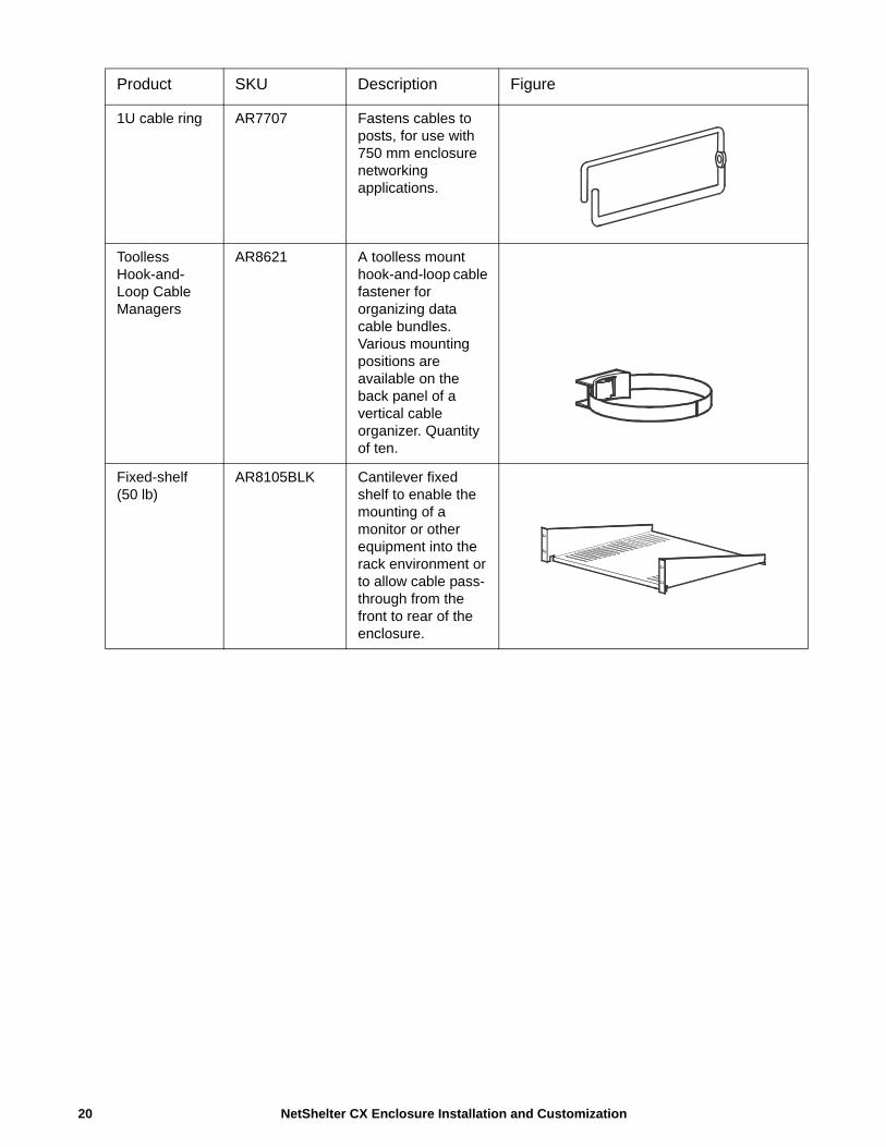
1U cable ring AR7707 Fastens cables to posts, for use with 750 mm enclosure networking applications.
Toolless Hook-and-Loop Cable Managers
AR8621 A toolless mount hook-and-loop cable fastener for organizing data cable bundles. Various mounting positions are available on the back panel of a vertical cable organizer. Quantity of ten.
Fixed-shelf (50 lb)
AR8105BLK Cantilever fixed shelf to enable the mounting of a monitor or other equipment into the rack environment or to allow cable pass-through from the front to rear of the enclosure.
Product SKU Description Figure
NetShelter CX Enclosure Installation and Customization
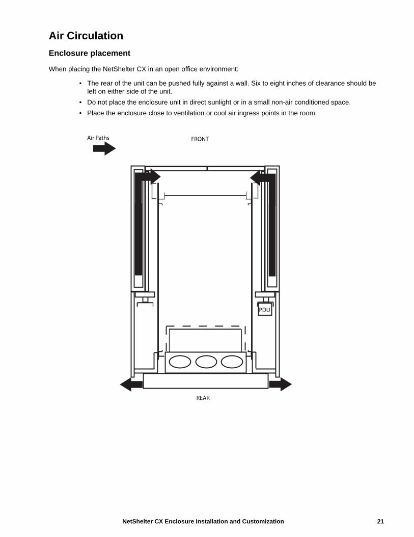
Air Circulation
Enclosure placement
When placing the NetShelter CX in an open office environment:
• The rear of the unit can be pushed fully against a wall. Six to eight inches of clearance should be left on either side of the unit.
• Do not place the enclosure unit in direct sunlight or in a small non-air conditioned space.
• Place the enclosure close to ventilation or cool air ingress points in the room.
PDU
FRONT
REAR
Air Paths
21 NetShelter CX Enclosure Installation and Customization
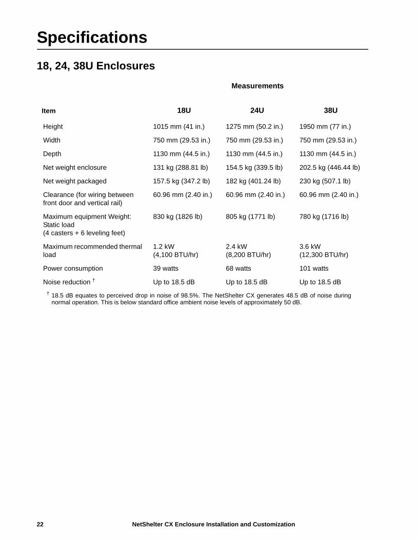
Specifications
18, 24, 38U Enclosures
Item
Measurements
18U 24U 38U
Height 1015 mm (41 in.) 1275 mm (50.2 in.) 1950 mm (77 in.)
Width 750 mm (29.53 in.) 750 mm (29.53 in.) 750 mm (29.53 in.)
Depth 1130 mm (44.5 in.) 1130 mm (44.5 in.) 1130 mm (44.5 in.)
Net weight enclosure 131 kg (288.81 lb) 154.5 kg (339.5 lb) 202.5 kg (446.44 lb)
Net weight packaged 157.5 kg (347.2 lb) 182 kg (401.24 lb) 230 kg (507.1 lb)
Clearance (for wiring between front door and vertical rail)
60.96 mm (2.40 in.) 60.96 mm (2.40 in.) 60.96 mm (2.40 in.)
Maximum equipment Weight: Static load (4 casters + 6 leveling feet)
830 kg (1826 lb) 805 kg (1771 lb) 780 kg (1716 lb)
Maximum recommended thermal load
1.2 kW (4,100 BTU/hr)
2.4 kW (8,200 BTU/hr)
3.6 kW (12,300 BTU/hr)
Power consumption 39 watts 68 watts 101 watts
Noise reduction † Up to 18.5 dB Up to 18.5 dB Up to 18.5 dB
† 18.5 dB equates to perceived drop in noise of 98.5%. The NetShelter CX generates 48.5 dB of noise during normal operation. This is below standard office ambient noise levels of approximately 50 dB.
NetShelter CX Enclosure Installation and Customization22
Two-Year Factory WarrantyThis warranty applies only to the products you purchase for your use in accordance with this manual.
Terms of warrantySchneider Electric warrants its products to be free from defects in materials and workmanship for a period of two years from the date of purchase. Schneider Electric will repair or replace defective products covered by this warranty. This warranty does not apply to equipment that has been damaged by accident, negligence or misapplication or has been altered or modified in any way. Repair or replacement of a defective product or part thereof does not extend the original warranty period. Any parts furnished under this warranty may be new or factory-remanufactured.
Non-transferable warranty This warranty extends only to the original purchaser who must have properly registered the product. The product may be registered at the Schneider Electric website, www.schneider-electric.com.
ExclusionsSchneider Electric shall not be liable under the warranty if its testing and examination disclose that the alleged defect in the product does not exist or was caused by end user’s or any third person’s misuse, negligence, improper installation or testing. Further, Schneider Electric shall not be liable under the warranty for unauthorized attempts to repair or modify wrong or inadequate electrical voltage or connection, inappropriate on-site operation conditions, corrosive atmosphere, repair, installation, exposure to the elements, Acts of God, fire, theft, or installation contrary to Schneider Electric recommendations or specifications or in any event if the Schneider Electric serial number has been altered, defaced, or removed, or any other cause beyond the range of the intended use.
THERE ARE NO WARRANTIES, EXPRESS OR IMPLIED, BY OPERATION OF LAW OR OTHERWISE, OF PRODUCTS SOLD, SERVICED OR FURNISHED UNDER THIS AGREEMENT OR IN CONNECTION HEREWITH. SCHNEIDER ELECTRIC DISCLAIMS ALL IMPLIED WARRANTIES OF MERCHANTABILITY, SATISFACTION AND FITNESS FOR A PARTICULAR PURPOSE. SCHNEIDER ELECTRIC EXPRESS WARRANTIES WILL NOT BE ENLARGED, DIMINISHED, OR AFFECTED BY AND NO OBLIGATION OR LIABILITY WILL ARISE OUT OF, SCHNEIDER ELECTRIC RENDERING OF TECHNICAL OR OTHER ADVICE OR SERVICE IN CONNECTION WITH THE PRODUCTS. THE FOREGOING WARRANTIES AND REMEDIES ARE EXCLUSIVE AND IN LIEU OF ALL OTHER WARRANTIES AND REMEDIES. THE WARRANTIES SET FORTH ABOVE CONSTITUTE SCHNEIDER ELECTRIC’S SOLE LIABILITY AND PURCHASER’S EXCLUSIVE REMEDY FOR ANY BREACH OF SUCH WARRANTIES. SCHNEIDER ELECTRIC WARRANTIES EXTEND ONLY TO PURCHASER AND ARE NOT EXTENDED TO ANY THIRD PARTIES.
IN NO EVENT SHALL SCHNEIDER ELECTRIC, ITS OFFICERS, DIRECTORS, AFFILIATES OR EMPLOYEES BE LIABLE FOR ANY FORM OF INDIRECT, SPECIAL, CONSEQUENTIAL OR PUNITIVE DAMAGES, ARISING OUT OF THE USE, SERVICE OR INSTALLATION, OF THE PRODUCTS, WHETHER SUCH DAMAGES ARISE IN CONTRACT OR TORT, IRRESPECTIVE OF FAULT, NEGLIGENCE OR STRICT LIABILITY OR WHETHER SCHNEIDER ELECTRIC HAS BEEN ADVISED IN ADVANCE OF THE POSSIBILITY OF SUCH DAMAGES. SPECIFICALLY, SCHNEIDER ELECTRIC IS NOT LIABLE FOR ANY COSTS, SUCH AS LOST PROFITS OR REVENUE, LOSS OF EQUIPMENT, LOSS OF USE OF EQUIPMENT, LOSS OF SOFTWARE, LOSS OF DATA, COSTS OF SUBSTITUENTS, CLAIMS BY THIRD PARTIES, OR OTHERWISE.
NO SALESMAN, EMPLOYEE OR AGENT OF SCHNEIDER ELECTRIC IS AUTHORIZED TO ADD TO OR VARY THE TERMS OF THIS WARRANTY. WARRANTY TERMS MAY BE MODIFIED, IF AT ALL, ONLY IN WRITING SIGNED BY AN SCHNEIDER ELECTRIC OFFICER AND LEGAL DEPARTMENT.
Warranty claims Customers with warranty claims issues may access the Schneider Electric customer support network through the Support page of the Schneider Electric website, www.schneider-electric.com/support. Select your country from the country selection pull-down menu at the top of the web page. Select the Support tab to obtain contact information for customer support in your region.
23 NetShelter CX Enclosure Installation and Customization


Worldwide Customer Support
Customer support for this product is available at www.schneider-electric.com.
8/2015990-3594C-001
© 2015 Schneider Electric. All rights reserved.