installation & owner’s manual all in one type air-source
TRANSCRIPT

Installation & Owner’s ManualALL IN ONE Type Air-source Heat Pump Water Heater
EcoSpring ES190
Thank you very much for purchasing our product,Before using your unit, please read this manual carefully and keep it for future reference.

ES190 Installation & Owner’s Manual
2
If you can’t make sure that your house power supply is earthed well, please don’t install the unit.The unit must be installed by a licensed tradesperson and in accordance with:• EcoSpring installation instructions.• AS/NZS 3500.4-”National Plumbing and Drainage Code
Hot Water Supply Systems-Acceptable Solutions”.• AS/NZS 3000-Wiring Rules.• Local authority regulations.• NZ Building Code.• Local Occupational Health and Satety (OH&S) Regulations.
This water heater must be installed by a licensed person as required by the Building Code. Only a licensed person will give you a compliance certificate, showing that the work complies with all the relevant standards.
Please read and understand this booklet.If you have any questions,please contact our service representative on 0800 200 510.
HOT WATER CAN BE DANGEROUS
NOTICE TO CUSTOMERS
� WARNING!
Warning – Hot water burns. As a safety precaution, young children should always be supervised around hot water fixtures.Heat pump water heaters can store water at temperatures that can cause scalding. Water temperaturesover 50°C can scald and care needs to be taken to ensure that injuries do not occur through incorrect use of your water heater.As heat pump water heaters can generate water temperatures in excess of 60°C, regulations require that a tempering valve be fitted to the heater to prevent water temperatures going to the home exceeding a preset safe maximum. The tempering valve must be connected to the hot water outlet line from the water heater. The valve must be fitted by an authorized plumber at the time of installation or in retrofitting to existing systems.Care should be taken to avoid coming into contact with any pipe work or fixtures associated with the water heater pipe lines. Under NO circumstances should any ‘home handy man’ type modifications be attempted.• This appliance is not intended for use by persons (including children) with reduced physical sensory or mental
capabilities, or lack of experience and knowledge, that prevents them from using the appliance safely withoutsupervision or instruction. Children should be supervised by a responsible person for their safety to ensure thatthey do not play with the appliance.
• DANGER: Failure to operate the relief valve easing gear at least once every six months may result in the waterheater exploding. Continuous leakage of water from the valve may indicate a problem with the water heater.
• THE INSTALLATION MUST COMPLY WITH THE REQUIREMENTS OF AS/NZS 3500.4, AS/NZS 3000, andall local codes and regulatory authority requirements. In New Zealand, the installation must conform tothe New Zealand Building Code G12.
The power supply must be protected by an individual circuit breaker at the main electrical supply switchboard and rated to suit the booster size. The supply to the heat pump water heater can be operated directly from the switchboard or via a remotely mounted switch or time clock as requested by the customer. The heater must be provided with a suitable means for disconnecting the power supply.
This unit is required reliable earthingbefore usage, may otherwise result in death or injury.
ES190 Installation & Owner’s Manual
3
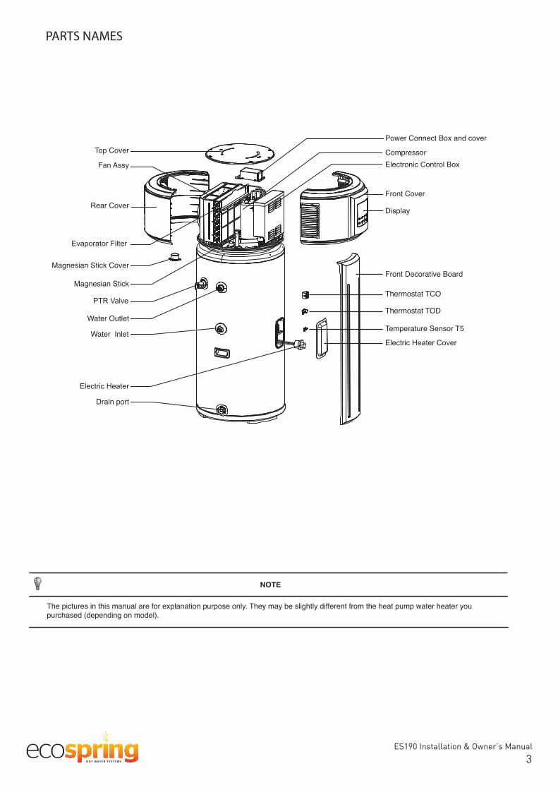
PARTS NAMES
NOTE
The pictures in this manual are for explanation purpose only. They may be slightly different from the heat pump water heater you purchased (depending on model).
Fan Assy
PTR Valve
Top Cover
Evaporator Filter
Magnesian Stick
Rear CoverFront Cover
Water Outlet
Water Inlet
Drain port
Electric Heater
Front Decorative Board
Temperature Sensor T5
Electronic Control Box
Power Connect Box and cover
Compressor
Display
Magnesian Stick Cover
Thermostat TOD
Thermostat TCO
Electric Heater Cover

ES190 Installation & Owner’s Manual
43Installation & Ownerʻs Manual
CONTENTS PAGE
WARNING
2. SAFETY INFORMATION
Please read thoroughly all of the instrucitons before installing oroperating the unit. The following safety warnings are very important, always read andobey all safety symbols:
● The unit must be earthed effectively.
● This appliance must be installed in accordance to AS/NZS stan-dards and the NZ Building code.
● A RCD breaker must be installed adjacent to the power supply.
● Do not remove, cover or deface any permanent instructions,lables, or the data label from either the outside of the unit orinside of unit panels.
● Only qualified persons should perform the installation of this unitin accordance with local national regulations and this manual.
Improper installation may result in water leakage, electric shockor fire.
● Ask qualified person for relocating, repairing and maintaining theunit.
Improper installation may result in water leakage, electric shockor fire.
● Electric connection work should comply with the instructions oflocal power company, local electric utility and this manual.
● Never use an incorrectly fuse rated, otherwise the unit may breakdown and risk of electrical fire.
● Do not insert fingers, rods or other objects into the air inletor outlet. The fan is rotating at high speed, and may cause injury.
● Never use a flammable spray such as hair spray, lacquer paintnear the unit. It may cause a fire.
● This appliance is not intended for use by persons (includingchildren) with reduced physical, sensory or mental capabilities,or lack of experience and knowledge, unless they have beengiven supervision or instruction concerning use of the appliance
NOTE
Above calculations are based on ideal conditions, the final amount will be different the actual running will vary with conditions, such as running period, ambient temperature, etc.
0 1 2 3 4 5 6 7 8 9 10 11 12 13
HWHP
Gas Burner
E-heater
Running Cost
Fig.1-1
1. BASIC OPERATION PRINCIPLE
We know from experience, the natural flow of heat, moves from ahigher to a lower temperature source, a heat pump can transfer heatfrom a lower temperature source to a higher temperature source withhigh efficiency.
The advantage of a heat pump water heater is that it can supply moreheat energy, normally 3:1 times than input electricity power byextracting the heat from ambient atmosphere in a free-of charge wayand transfer to Sanitary Hot Water. Compared to a traditional waterheater, such as electric water heater or gas burner water heater, theirefficiency is normally less than 1:1, which means you can dramaticallycut off the bill of family daily SHW by the application of heat pumpwater heater, the following examples will show more details.
Power consumption comparison under the same condition to heat 1ton of water from 15˚C to 55˚C.
Q=cM(T1-T2)=1(kCal/kg*℃)X1000(kg)X(55-15)(℃)=40000kCal=168MJ=46.67kW*h
3
3
4
6
8
11
14
16
17
BASIC OPERATION PRINCIPLE..........................................................
SAFETY INFORMATION......................................................................
BEFORE INSTALLATION......................................................................
INSTALLATION......................................................................................
OPERATING INSTRUCTIONS...........................................................
OPERATION ..........................................................................................
TROUBLE SHOOTING.........................................................................
MAINTENANCE.....................................................................................
SPECIFICATIONS..................................................................................
Table 1-1HPWH Gas Burner E-heater
EnergyResource Air,Electricity Gas Electricity
Transfer Factor 860kCal/kW*h 8905kCal/m³ 860kCal/kW*h
AverageEfficiency
(W/W)3.5 0.8 0.95
Unit Cost 0.25 NZD/kW*h 2.2C/MJ 0.25 NZD/kW*h
Running CostNZD
12.28 4.623.33
13.33kW*h 210MJ 49.13 kW*hEnergyConsumption

ES190 Installation & Owner’s Manual
54
Installation & Owner‘s Manual
Table 3-1
Accessory Name Qty. Sharp Purpose
1Owner’s and Installation Manual
Installation and user instructions
1Drain pipe for water condensation
Used to drain water condensation (has been connected to the lower condensate drain port)
by a person responsible for their safety. Children should besupervised to ensure that they do not play with the appliance.
● If the supply cord is damaged, it must be replaced by themanufacturer or its service agent or a similarly qualified person.
● DISPOSAL: Do not dispose this product asunsorted municipal waste. Collection of suchwaste separately for special treatment is neces-sary. Do not dispose of electrical appliances asunsorted municipal waste, use separate collec-tion facilities. Contact your local government forinformation regarding the collection systemsavailable.
3. BEFORE INSTALLATION
3.1 Unpacking
3.1.1 Accessories
3.1.2 How to transport
1) In order to avoid scratching or deformingthe unit surface, apply guard boardsto the contacting surfaces.No contact of fingers and other thingswith the vanes.Don’t incline the unit more than 45°in moving, and keep it vertical wheninstalling.
2) This unit is heavy, it needs to be carried by two or more persons,othewise might cause injury and damage.
3.2 Location requirements
1)preserved.
2) The air inlet and outlet should be free from obstacles and strongwind.
3) The base surface should be flat, surface should be inclined nomore than 2° and able to bear the weight of the unit and suitablefor installing the unit without increasing noise or vibration.
4) The operating noise and air flow expelled should not affectneighbors.
5) No flammable gas nearby.
6) It should be convenient for piping and wiring.
7) If it is installed in indoor space, it might cause indoor temperatureto decrease and noise disturbance, Please take preventivemeasures for this.
8) If the unit has to be installed on a metal part of building, makesure the electric insulation meets the relevant local electric
Gradient limit>45°
CAUTION
● The earthing pole of socket must be well grounded, make surethat power supply socket and plug are dry and connected tightly.
● Before cleaning, be sure to stop the operation and turn thebreaker off or pull out the power plug. Otherwise, an electricshock and injury may be caused.
● Water temperature over 50℃ cancause severe burns instantly ordeath from scalds. Children,disabled and elderly are athighest risk of being scalded.Feel water before bathing orshowering. Water temperaturelimiting valves are required as
● Do not operate the unit with a wet hand. An electric shock maybe caused.
● The installation height of power supply should be over 1.8m, ifthere is any water exposure, steps must be taken to separatethe power supply from water.
well as an isolation value.
during operation. But, if there is a large volume of water, callyour service agent for instructions. After long term use, checkthe unit base and fittings. If damaged, the unit may sink, resultingin injury. Arrange the drain pipe to ensure smooth draining.Improper drainage work may cause wetting of the building,furniture etc. Do not touch the inner parts of the controller orremove the front panel. Some parts inside are dangerous totouch, and damage may be caused.
● Do not turn off the power supply.
System will stop or restart heating automatically. A continuouspower supply for water heating is necessary, except serviceand maintenance.
Film Label 1 Protects display during transit. Please remove after installation.

ES190 Installation & Owner’s Manual
65Installation & Ownerʻs Manual
3.4 If installed in inclosed space
The water heater must be located in a space >15m³, and must have unrestricted air flow. As an example, a room that has an 2.5 tall ceiling and is 3 meter long by 2 meter wide would contain 15m³ .
3.5 Unit outline dimension (unit: mm)
Fig.3-2
Fig.3-1
B
HA
Table 3-2
H 1580
A 568
560B
RSJ-15/190RDN3-B
Dimension
Model
600
500
300
Display
Barrier600
600
300 300
Air outlet
3.3 Maintenance space requirements (unit: mm)
● The ambient air temperature must also be considered wheninstalling this unit, in heat pump mode the ambient air tempera-ture must be above 5℃ and below 43 If the ambient airtemperature falls outside these upper and lower limits,theelectrical elements will activate to meet the hot water demandand the heat pump will not operate.
●temperatures. A unit located in unconditioned spaces (i.e.,garages, basements, etc.) may require the water piping, conden-sate piping, and drain piping to be insulated to shelter agianstfreezing.
CAUTION
CAUTION
WARNING
may result.
in a location protected from the wind.
Installing the unit in any of the following places may lead to malfunction (If it is inevitable, consult the supplier prior to purchase).
machines.
● Seaside or where the air contains salt.
● Hot spring area where corrosive gases exist, e.g., sulfide gas.
● Factories where the power voltage fluctuates seriously.
● Inside a car or cabin.
way to avoid these, please install a cover.
The circulating air for every unit should be more than 350m3
Make sure there is enough installation space. dimensional drawing (see Fig.3-1,Fig.3-2)

ES190 Installation & Owner’s Manual
76Installation & Ownerʻs Manual
4. INSTALLATION
3) Ifter conection of the water system piping work, turn on the coldwater inlet valve and hot water outlet valve and bleed all air fromthe tank. When water flows smoothly out from water outlet pipe(tapwater outlet), the tank is full, turn off all valves and check pipelineto make sure there is no any leakage.
4) If the inlet water pressure is less than 0.15MPa, a pump should beinstalled at the water inlet.
5) Condensate may leak from unit if drainage pipe is blocked, adrainage pan is recommended as shown as following figure:
1) Installation of the water inlet or outlet pipes: The water inletoutlet thread is thread). Pipes must beheat-resistant and durable.
HandleDrainagepipe
WARNING
CAUTION
● Piping water system as the above figure. In case of installingwhere outside temperatures fall below 5℃, insulation must beprovided for all hydraulic components.
●6 month to make sure that there is norestriction of the valve. Please beware ofthe hot water from the valve. The drainagepipe should be well insulated in order toprevent water inside pipe from freezing incold weather.
Fig.5.1
Pipeline Connection Schematic
Water Outlet
User
Water Inlet
Barrel-drain
Drain port
UpperCondensate Outlet
LowerrCondensate Outlet
User
User
4.1
Pressure Limiting&Strainer& Non-return valve
Cold water expansion valve

ES190 Installation & Owner’s Manual
87
Installation & Ownerʻs Manual
4.3.1 Electric Wiring Illustration
CAUTION
4.3 Electric Connection
Fig.4-250mm larger than
the dia. of unit
Max. 22mmHeat Pump Water Heater
WARNING
4.4 Installation checklist4.4.1 Location
1) The flooring beneath the water heater must be able to supportthe weight of the water heater when filled with water (286kg full).
2) Located indoors (such as a basement or garage) and in avertical position. Sheltered from freezing temperatures.
4.2 Installation requirement
To smoothly drain condensate from unit, please install the main unit ison a horizontal floor. Otherwise, please ensuring the drain vent is at
groundshould be no more than 2°.
● Set the electric leakage protector according to the relevantelectric technical standards of the State.
● The power cord and signal cord shall be laid out neatly andproperly without mutual interference or contacting the connec-tion pipe or valve.
-tion before power is turned on.
Fig.4-3
Draino
Drainand must be effectively earthed.

ES190 Installation & Owner’s Manual
9Installation & Ownerʻs Manual
8
5.1 Operation steps
5. OPERATING INSTRUCTIONS
Water Filling
Hot water outlet
Close
Water out
When water flows out from the water outlet, the tank is full. Turn off the hot wateroutlet valve and water filling is finished.
Open
Open the cool water inlet valve and the hot water outlet valve.
Cool water inlet Hot water outlet
Open
Fig.5-1
Before using this unit, please follow the steps below.
Filling with water: If the unit is used for the first time or used again afteremptying the tank, please make sure that the tank is full of waterbefore turning on the power.Method: see Fig.5-1.
CAUTION
Close
Open
Drainpipe shut-off valve
Open
Cool water inlet
Close the cool water inlet valve, open the hot water outlet valve and open drainpipe.
Hot water outlet
● After powered on, the display lights up. Users can operate theunit through the buttons under the display.
●should be emptied. Method: See Fig.5-2:
● Operation without water in water tank may result in the damageof auxiliary e-heater. In case of such damage, the manufacturerwill not be liable for any damages caused by this issue.
3) Provisions made to shelter the area from water damage.Metal drain pan installed and piped to an adequate drain.
4) Sufficient room to service the water heater.
5) Sufficient air for the heat pump to function, the water heatermust be located in a space >15m³, and must have unrestrictedair flow.
6) The unit cannot be placed into any type of closet or smallenclosure.
7) The site location must be free from any corrosive elements inthe atmosphere such as sulfur, fluorine, and chlorine. Theseelements are found in aerosol sprays, detergents, bleaches,cleaning solvents, air fresheners, paint, and varnish removers,refrigerants, and many other commercial and householdproducts as well as naturally occuring environments. Inaddition excessive dust and lint may affect theoperation of the unit and require more frequent cleaning.
8) The ambient air temperature must be above 5ºC and below43ºC.If the ambient air temperature falls outside these upperand lower limits the electrical element will be activated tomeet the hot water demand.
4.4.2 Water System Piping
installed with a discharge pipe run to an adequate drain andsheltered from freezing.
2) All piping properly installed and free of leaks.
3) Unit completely filled with water.
4) Tempering valve installed per manufacturerʼs instructions.Condensate Drain Line Installed.
Must be located with access to an adequate drain orcondensate pump.
Condensate drain lines installed and piped to an adequatedrain or condensate pump.
4.4.3 Electrical Connections
2) Wiring size and connections comply with all local applicablecodes and the requirements of this manual.
3) Water heater and electrical supply are properly grounded.
4) Correctly sized overload fuse or circuit breaker protectioninstalled.
4.4.4 Post Installation Review
1) Understand how to use the User Interface Module to set thevarious modes and functions.
2)of the condensate drain pan and lines. This is to help preventany possible drain line blockage resulting in the condensatedrain pan overflowing.
3)indicator that both condensation drain lines may be blocked.Immediate action is required.
4) To maintain optimal operation check, remove and clean the air

109
Installation & Ownerʻs Manual
Fig.5-2
Emptying
Drainpipe shut-off valve
Close
After emptying, please replace the nut of drainpipe.
5.2 Trial- running
5.2.1 Check list before commissioning.
1) Check list before trial-running.
2) Correct installation of the system.
3) Correct connection of water/air piping and wiring.
4) Condensate draining smoothly well insulated for all hydraulicpart.
5) Correct power supply.
6) No air in the water pipeline and all valves opened.
7) Effective RCD installed.
8) Sufficient inlet water pressure (between 0.15MPa and 0.70MPa)(150-700kPa).
5.2.2 Operating Capability
1) This unit has two kinds of heat sources: Heat pump(compressor) and electric heater.The unit has one temperature sensor, which is installed at theupper portion of the tank.
2) Heat Pump Modes
2.1) Economy Mode: In this mode, only the heat pump system is in operation.
TankWater temperature sensor
Electric heater
Water inlet
Water outlet
Fig.5-3
The unit can operate with three modes: Economy Mode,Hybrid Mode and e-heater Mode.Economy mode is the normal mode.
The suitable operating ambient air temperature range is 5~43°C. (Water outlet temperature range 38~65°C, runningambient 5~43°C). 2.2) 2.3)
Hybrid Mode: In this mode, the system will adjust the working capabilities of e-heater and heat pump according to the tankwater temperature. The system can heat water by the heat pump,e-heater, or together in this mode. The suitable operating airambient range is -20~43°C. (Water outlet temperature range38~70°C, running ambient -20~43°C).In this mode, if ambient air temperature is lower than 5°C,e-heater is the only heat source. If the ambient temperature isbetween 5°C and 10°C, e-heater and the heat pump will activatetogether. If the ambient temperature is higher than 10°C, it willonly activate the heat pump when water temperature is lowerthan 65°C. When water temperatur is above 65°C, only thee-heater will activate.
e-heater: In this mode, only the element will be used to heat thewater. (Water outlet temperature range 38~70°C, runningambient -20~43°C).
3) Water Temperature DisplayThe temperature shown on the display depends on the watertemperature sensor. It is normal that sometimes the display tempera-ture decreases while the unit is running, it is caused when thenatural convection of the upper hot wate mixes with by the bottomcold water which flows from inlet tap.
4) Operating mode should be selected manually. Refer to table 5-1.Running Temperature Range Water temperature limits:
Defrosting During Water-heating In heat pump running period, if the evaporator becomes frosted inlower ambient temperature, the system will defrost automaticallyto keep effective performance (about 5~15min). At defrosting time,the compressor will stop, but fan motor will still run.Heat-up Time There are different heat-up times at different ambient tempera-tures. Normally lower ambient temperature result in longer heat-uptimes because of lower effective performance.
5) Heat Source Shift
The default heating source is heat pump.If ambient temperature range is out of heat pump operating range,heat pump will stop running, the unit will shift automatically to activatee-heater and show the icon LA on the display, then if the ambienttemperature goes into the running range of heat pump again, it willstop e-heater and shift automatically to heat pump again, and theicon LA will be extinguished.
If the target water temperature is higher than maximum tempera-ture (Heat pump), the unit will activate heat pump firstly to themaxinum temperature, then stop heat pump, activate e-heater tocontinually heat water to the target temperature.
NOTE
If only using e-heater mode, approx 60% of the tank water will beheated, so set a higher target water temperature if the ambienttemperature is out of the heat pump running range.
NOTE
If the system continuously reports heat pump protection, the latesterror code and will be shown on the display, then heat pump willstop running, and the unit will shift automatically to e-heater modeas the backup mode, but the code and will be shown until poweris reset.
--
65
Ambient temp. range
Maxinum temp.(Heat pump)
Table 5-1
Setting temp. range
Operationmode
Economy mode
Hybrid mode
E-heater mode
5~43
-20~43
-20~43
38~70
38~65
38~70
65
2.2)
2.3)

ES190 Installation & Owner’s Manual
1110Installation & Ownerʻs Manual
NOTE
While the ambient temperature is below 5℃, heat pumpefficiency will decrease dramatically, the unit will automaticallyshift to E-heater mode.
⑤ About TCO and TODThe power of compressor and E-heater will be automaticallyshut-off or turn on by TCO and TOD.
● If the water temperature is higher than 78℃, the TOD will automati-cally shut off the power of compressor and E-heater, and turn it onit if the temperature fall down below 68℃.
● If the water temperature is higher than 85℃, the TCO will automati-cally shut off the power of compressor and E-heater, it must bereset by an authorised service technician.
⑥ Restart After a Long Term StopWhen the unit is restarted after a long term stop (trail runningincluded), it is normal that outlet water is unclean. Turn the tap onand the water will be flushed clean.
5.2.3 Basic function
1) Weekly disinfect functionUnder disinfection mode, unit immediately starts to heat water upto 65℃ to kill any potential of legionella bacteria inside water oftank, icon will light on the display screen during disinfection;Unit will quit disinfection mode when water temperature is higherthan 65℃ and extinguish icon.
2) How to turn on the unit:If unit is OFF->press ->button will be unlocked ->press
to select mode ->press to set target watertemperature->press ->unit will automatically select mode
and start to heat water to target temperature.
Fig.5-4
500
1000
1500
2000
2500
3000
5 7 15 20 25 30 32 35 40 43
Cap
acity
(W)
Ambient temp(℃)
15-4515-5515-65
Fig.5-5
1
2
3
4
5
6
7
5 7 15 20 25 30 32 35 40 43
CO
P(W
/W)
Ambient temp(℃)
15-4515-5515-65
Fig.5-6
0 : 00: 00
2 : 24: 00
4 : 48: 00
7 : 12: 00
9 : 36: 00
12: 00: 00
14: 24: 00
5 7 15 20 25 30 32 35 40 43
Tim
e(h)
Ambient temp(℃)
15-4515-5515-65
Recovery Time
Defrosting during Water-heating
If the evaporator freezes over in Economy Mode and HybridMode during cold weather, the system will defrost automaticallyto keep effective performance(3~10 min).
In defrosting mode, the fan motor will run at a high speed andE-Heater will operate.
Ambient Temperature
The systemʼs operational temperature is between -20℃~43℃The following are the operation temperatures for each mode.
Economy Mode: 5℃~43℃
Hybrid Mode: -20℃~43℃
E-Heater Mode: -20℃~43℃
Mode SelectionThe different modes are designed to meet different demandsand the following are recommended selections.
Economy Mode: 5~43℃, a continuous hot water demand below150L(65℃);
Hybrid Mode: -20℃~43℃, a continuous hot water demandbetween 150L~200L(70℃);
E-Heater Mode: -20℃~43℃, a continuous hot water demandbetween 150L~200L(70℃).
Self-Protection Apparatuses
When the self-protection occurs, the system will be stopped andwill begin self-check, and restart when the protection resolved;
When the self-protection happens, the buzzer will buzz in everyother minute, the ALARM indicator will flash and the display willindicate the error code and water temperature alternatively.Press CANCEL key for 3sec to stop the alarm. All stop when theprotection is resolved and error code disappears from thedisplay.
In the following circumstances, self-protection starts:
Air inlet or outlet is blocked;
The evaporator is covered with too much dust;
Incorrect power supply (exceeding the range of 220-240V)
NOTE
When self-protection happens, cut the power supply manuallyand restart after the error resolved.

ES190 Installation & Owner’s Manual
1211Installation & Ownerʻs Manual
6. OPERATION
6.1 Control Panel Explanation
6.2 Display ExplanationFig. 6-1
Display
Operation
Fig.6-2
① ② ③ ④ ⑤ ⑥ ⑦ ⑧ ⑨
10
11
12
13 14 1615 17 18 19
11
10
12
13
⑤
⑥
⑦
⑨
⑧
WATER TEMP will be displayed all the time. shows water temperature on normal time; shows setting temperature when setting temperature;
No Icon Description
DISINFECTION:will be displayed when the unit is in
disinfection mode, otherwise will beextinguished.
LOCK:will be displayed if buttons are locked,
otherwise will be extinguished.
ECONOMY MODE:will be displayed if unit is operating
will flash with 1Hz frequency if
HYBRID MODE: will be displayed if unit is operating in Hybrid Mode. When selecting mode, will flash with 1Hz frequency if Hybrid Mode is selected at the off time.
E-HEATER MODE:will be displayed if unit is operating
will flash with 1Hz frequency if
ALARM:When unit is displayingwill flash with 5Hz frequency as well as buzzer sounding 3 times every minute until
second.
HIGH TEMP:If target water temp. is higher than 50℃, will be lightened , otherwise will be extinguished.
FILL WATER:will be displayed and flash with 1Hz
frequency when the unit is re-powered on ifthe unit was off at last time of power on,then if press once, will be displayedwithout flashing,then press again, willbe extinguished all the time. will not bedisplayed when the unit is re-powered on ifthe unit was on at last time of power on.
TEMP-UNIT will be displayed if displays temperature, otherwise will be extinguished.
Table 6-1
①
②
③
AMBIENT TEMP OUTSIDE THE OPERATIONALRANGE OF HP:
will be displayed if the ambient temp. isnot in the operating range of the heat pump,otherwise will be extinguished.
④
WIRE CONTROLLER (Reserved function):will be displayed if connected to a wire
controller, otherwise will be extinguished.
COMPRESSOR:will be displayed if compressor is activated,
otherwise will be extinguished.
No Icon Description
E-HEATER:will be displayed if e-heater is activated,
otherwise will be extinguished.14
ES190 Installation & Owner’s Manual
1312Installation & Ownerʻs Manual
Fig. 6-3
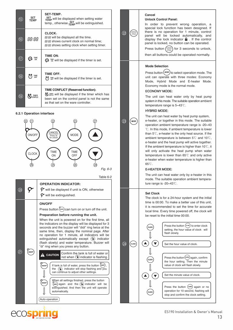
6.2.1 Operation interface
20 21 22 23 27
24 25 26 28
Table 6-2
21
20
23
22
24
Mode Selection
Press button to select operation mode. The
The unit can heat water only by heat pumpsystem in this mode. The suitable operation ambienttemperature range is 5~43℃.
The unit can heat water by heat pump system,e-heater, or together in this mode. The suitableoperation ambient temperature range is -20~43℃. In this mode, if ambient temperature is lowerthan 5℃, e-heater is the only heat source. If theambient temperature is between 5℃ and 10℃,e-heater and the heat pump will active together.If the ambient temperature is higher than 10℃, itwill only activate the heat pump when watertemperature is lower than 65℃ and only activee-heater when water temperature is higher than65℃.
The unit can heat water only by e-heater in thismode. The suitable operation ambient tempera-ture range is -20~43℃.
CancelUnlock Control Panel:In order to prevent wrong operation, aspecial lock function has been designed. Ifthere is no operation for 1 minute, controlpanel will be locked automatically, anddisplay the lock indicator . If the controlpanel is locked, no button can be operated.Press button for 3 seconds to unlock,
then all buttons could be operated normally.
15
16
17
18
19
SET-TEMP will be displayed when setting water temp., otherwise will be extinguished.
OPERATION INDICATOR: will be displayed if unit is ON, otherwise will be extinguished.
CLOCK will be displayed all the time. shows current clock on normal time; shows setting clock when setting timer.
TIME CONFLICT (Reserved function)will be displayed if the timer which has
been set on the control panel is not the sameas that set on the ware controller.
TIME OFF will be displayed if the timer is set.
TIME ON will be displayed if the timer is set.
Set Clock The clock is for a 24-hour system and the initialtime is 00:00. To make a better use of this unit,it is recommended to set the time for accurate
be reset to the initial time 00:00.
Press the button to enter clocksetting, the hour value of clock willflash slowly.
Press the button again or nooperation for 10 second, flashing willstop and confirm the clock setting.
Press the button again, confirmthe hour setting. Then the minutevalue of clock will flash slowly.
Set the hour value of clock.
Set the minute value of clock.
Auto-operation
If tank is full of water, press the button ,the indicator will stop flashing and you
When all settings finished, press the buttonagain and the indicator will be
extinguished. And then the unit will operateautomatically.
CAUTION
ON/OFFPress button can turn on or turn off the unit.Preparation before running the unit.When the unit is powered on for the first time, allthe indicators on the display will be displayed for 3
same time, then, display the nominal page. Afterno operation for 1 minute, all indicators will beextinguished automatically except indicator(flash slowly) and water temperature. Buzzer will
Confirm the tank is full of water or not when indicator is flashing.

ES190 Installation & Owner’s Manual
1413Installation & Ownerʻs Manual
25
26
Set Timer-TIME ON ONLYTime on only:
automatically operate once between the settingof the clock and the last 24 hours.
Cancel Timer-TIME ON ONLYIn the unlocked state, press the button for 3
canceled.
Set Timer-TIME ON & TIME OFFTime on & Time off:
will automatically operate between the setting
minutes automatically.
Press the button to enter
value of the clock will flash slowly.
Pressing the button again or nooperation for 10 second, flashing will
setting.
Press the button again, confirmthe hour setting. Then the minutevalue of clock will flash slowly.
Set the hour value of clock.
Set the minute value of clock.
Set the hour value of clock.
Set the minute value of clock.
27
28
Cancel Timer-TIME ON&TIME OFF In the unlocked state, press the button for more
function will be canceled.
INCREASE/UPIf button is unlocked, corresponding value willincrease by pushing .
than 1s, temperature value will be increasedcontinuously;
continuously.
DECREASE/DOWNIf button is unlocked, corresponding value willdecrease by pushing .
than 1s, temperature value will be decreasedcontinuously;
●
continuously.
Press the button to enter
value of the clock will flash slowly.
Press the button again, confirmthe hour setting. Then the minutevalue of clock will flash slowly.
Pressing the button again or nooperation for 10 second, flashing will
OFF setting.
Press the button to enter
value of the clock will flash slowly.
Pressing the button again or nooperation for 10 second, flashing will
setting.
Press the button again, confirmthe hour setting. Then the minutevalue of clock will flash slowly.
Set the hour value of clock.
Set the minute value of clock.
15Installation & Ownerʻs Manual
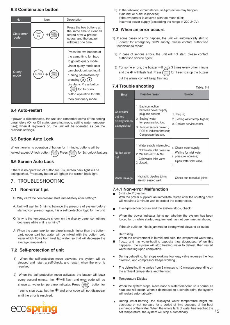
6.3 Combination button
7. TROUBLE SHOOTING
7.1 Non-error tips
Q: Why canʼt the compressor start immediately after setting?
A: Unit will wait for 3 min to balance the pressure of system beforestarting compressor again, it is a self protection logic for the unit.
Q: Why is the temperature shown on the display panel sometimesdecrease while unit is running?
A: When the upper tank temperature is much higher than the bottompart, upper part hot water will be mixed with the bottom coldwater which flows from inlet tap water, so that will decrease theaverage temperature.
7.2 Self-protection of unit
1) When the self-protection mode activates, the system will bestopped and start a self-check, and restart when the error isresolved.
2) When the self-protection mode activates, the buzzer will buzzevery second minute, the will flash and error code will beshown at water temperature indicator. Press button for
1sec to stop buzz, but the and error code will not disappearuntil the error is resolved.
Table.7-1
rror Possible reason Solution
Cold waterout anddisplay screenextinguished
No hot waterout
Water leakage Hydraulic pipeline ointsare not sealed well.
Bad connectionbetween power supplyplug and socket;Setting watertemperature too low;Temper sensor broken ;PCB of indicator broken;Compressor broken.
1. Plug in;2. Setting water temp. higher;3. Contact service center.
Check water supply;Waiting for inlet waterpressure increase;Open water inlet valve.
Check and reseal all oints.
Water supply interrupted;Cold water inlet pressure too low (<0.15 Mpa);Cold water inlet valve closed.
1.
2.
3.
1.
2.
3.
1.
2.
3.
6.4 Auto-restart
If power is disconnected, the unit can remember some of the settingparameters (On or Off state, operating mode, setting water tempera-ture); when it re-powers on, the unit will be operated as per theprevious settings.
6.5 Button Auto Lock
When there is no operation of button for 1 minute, buttons will be locked except Unlock button , Press for 3s, unlock buttons.
6.6 Screen Auto Lock
If there is no operation of button for 30s, screen back light will be extinguished.Press any button will lighten the screen back light.
No. Icon Description
Clear error code
Querymode
+
+
Press the two buttons at the same time to clear all stored error & protect codes, and the buzzer will buzz one time.
Press the two buttons at the same time for 1sec to go into query mode. Under query mode user can check unit setting & running parameters by pressingcircularly. Press button for 1s or no button operation for 30s, then quit query mode.
3) In the following circumstance, self-protection may happen:If air inlet or outlet is blocked;If the evaporator is covered with too much dust;
7.3 When an error occurs
1) If some cases of error happen, the unit will automatically shift to
technician to repair.
2) In case of serious errors, the unit will not start, please contactauthorised service agent.
3) For some errors, the buzzer will buzz 3 times every other minuteand the will flash fast. Press for 1 sec to stop the buzzer
but the alarm icon will keep flashing.
7.4 Trouble shooting
7.4.1 Non-error Malfunction3-minute ProtectionWith the power supplied, an immediate restart after the shutting downwill require a 3 minute wait to protect the compressor.
If self-protection occurs and the system stops, check :
When the power indicator lights up, whether the system has beenforced to run while startup requirement has not been met as above;
DefrostingWhen the environment is humid and cold, the evaporated water mayfreeze and the water-heating capacity thus decreases. When thishappens, the system will stop heating water to defrost, then restartwater-heating upon completion.
During defrosting, fan stops working, four-way valve reverses the flowdirection, and compressor keeps working.
The defrosting time varies from 3 minutes to 10 minutes depending onthe ambient temperature and the frost.
Temperature Display
When the system stops, a decrease of water temperature is normal asheat loss will occur. When it decreases to a certain point, the systemwill restart automatically;
During water-heating, the displayed water temperature might stilldecrease or not increase for a period of time because of the heatexchange of the water. When the whole tank of water has reached theset temperature, the system will stop automatically. 14

ES190 Installation & Owner’s Manual
1615Installation & Ownerʻs Manual
The diagnostic codes listed above are the most common. If a diagnostic code not listed above is displayed, contactresidential technical assistance referencing the number on the front of this manual.
NOTE
7.5 Error code shooting table
Table.7-2
Malfunction Description Corrective action
rror of sensor T5L(lower water temperature sensor)
1
Maybe the connection between sensor and PCB isbroken or sensor has been broken.Contact a qualified person to service the unit.
Tank and wired controller communication error2The connection between controller and PCB isbroken or PCB has been broken.
vaporator temperature sensor T3 error4 The connection between sensor and PCB is
broken or sensor has been broken.Contact a qualified person to service the unit.
Ambient temperature sensor T4 error
5
The connection between sensor and PCB isbroken or sensor has been broken.Contact a qualified person to service the unit.
Compressor discharge temperature sensor TP error
6
The connection between sensor and PCB isbroken or sensor has been broken.Contact a qualified person to service the unit.8
Some wires have been broken or bad wiringconnection.Contact a qualified person to service the unit.
If PCB current_induction_circuit check the currentdifference between L,N >14mA, system consider it as"electric leakage error"
lectric leakage error
Compressor suction temperature sensor TH error
9
The connection between sensor and PCB isbroken or sensor has been broken.Contact a qualified person to service the unit.
-heater open-circuit protection (I H(Current difference-heater on & e-heater off )<1A)
Maybe the -heater has been broken or bad wiringconnection after repair.
P2
High discharge temperature protectionTp>115℃, Protection activeTp<90℃, Protection inactive
System blocked, air or water or lowrefrigerant(leakage) in system (after repair), watertemperature sensor malfunction, etc.Contact a qualified person to service the unit.
Compressor overloaded protection (10 secs aftercompressor start up), Current checking starts ,1)only compressor running, if it is >7A , the
compressor will be stopped and protected.2)Compressor+e-heater opend, if it is >I H+7,the
compressor will be stopped and protected.
Compressor broken, system blocked,air or water or too much refrigerant in system (afterrepair), water temperature sensor malfunction, etc.
℃
When the ambient temp T4 is out of Heat Pumprunning range (5 43℃) Heat Pump will stop, unit willshow LA on the position of clock on display until T4back to (5 43 ).
It is normal, and not necessary to repair.
Display
P8
P2
P4
LA

ES190 Installation & Owner’s Manual
1716Installation & Ownerʻs Manual
8.2 Recommended regular maintenance table
CheckingItem
Checkingcontent Checking frequency Action
1 air filter(inlet outlet) every month Clean the filter
2 anode rod every half year eplace if required
3 inner tank every half year Clean the tank
4
5
e-heater every half year Clean e-heater
Operate the
valve to ensure that waterways are clear.
If water doesn't flow freely when operating the
every year
Table.8-1
8. MAINTENANCE
8.1 Maintenance
1) Check the connection between power supply plug and socketand ground wiring regularly;
2) In some cold areas (below 0℃), if the system will be stopped fora long time, all the water should be released in case of freezing
3)regularly to keep an efficient performance.
4) Check the anode every half year and change if required. Formore details, please contact the supplier or the service.
How to Change the anode
Turn off the power, and turn off the water inlet valve.
● Open hot water tap, and decrease the pressure of the innercontainer.
Open the drain port, and release about 20L water.
Unscrew anode according to instruction.
Open cold water valve until hot water flows out, and turn off thehot water tap.
How to Take Off The Air Filter remove screw from top cover.
Take the top cover,and slide out the filter
counter clockwise
When installing the top cover please refer to the direction of arrow, after assembling it should be line up.
NOTE
5) Clean the air filter every year to maintain heating performance.
The method to dismantle the filter is: unscrew the air inlet ring,take out the filter and clean it completely, finally, remount tothe unit. For unit with duct, remove duct first then follow aboveinstruction.

ES190 Installation & Owner’s Manual
1817Installation & Owner‘s Manual
9. SPECIFICATIONS
The test conditions: ℃
Water temperature from 15 up to 45℃.
Model
High-pressure Protector, Over-load Protector,
134a(0.8kg)
Protection
Compressor power
Outlet water temp.
Water side exchanger
Inlet Pipe Dia.
Outlet Pipe Dia.
Material
Motor power
Outlet Air Type
Net Weight
Surface heat exchanger
Hydrophilic aluminum fin, inner groove copper tube
40W
Air out from sideward
440W
2150W
0.7MPa
Water Tank Cap.
Water-heating Cap.
Mode
1500W
Rated input power /Current 2150W 9.3A
Power supply 220 ~ 50Hz
2150W
Hybrid Mode
1500W 2150W
Heat Pump
Drainpipe Dia.
DN20
DN20
DN20
DN20
90kg
190L
Wat
er p
ipel
ine
syst
emA
ir si
de
Dimension
Default 60℃,(38℃-70℃ )
Table. 9-1
Fusible Link Type
Operation control
17Installation & Owner‘s Manual
9. SPECIFICATIONS
The test conditions: ℃
Water temperature from 15 up to 45℃.
Model
High-pressure Protector, Over-load Protector,
134a(0.8kg)
Protection
Compressor power
Outlet water temp.
Water side exchanger
Inlet Pipe Dia.
Outlet Pipe Dia.
Material
Motor power
Outlet Air Type
Net Weight
Surface heat exchanger
Hydrophilic aluminum fin, inner groove copper tube
40W
Air out from sideward
440W
2150W
0.7MPa
Water Tank Cap.
Water-heating Cap.
Mode
1500W
Rated input power /Current 2150W 9.3A
Power supply 220 ~ 50Hz
2150W
Hybrid Mode
1500W 2150W
Heat Pump
Drainpipe Dia.
DN20
DN20
DN20
DN20
90kg
190L
Wat
er p
ipel
ine
syst
emA
ir si
de
Dimension
Default 60℃,(38℃-70℃ )
Table. 9-1
Fusible Link Type
Operation control
Warranty 3 Year Comprehensive