installation & operators manual rpr 400c
TRANSCRIPT
Installatio
n &
Op
erators M
anu
al
RPR 400C


Manual # 016-0171-038 Rev A 03/06
1
C H A P T E R
I N T RO D U C T I O N
Congratulations on your purchase of the Raven 400C Receiver! This receiver will provide you with highly accurate and reliable GPS navigation and positioning solutions. GPS/DGPS receiver performance is the key to successful yield mapping and monitoring, swathing, and other precision farming functions. The 400C is designed to meet these needs while operating in the rugged agricultural environment. A front panel display is provided to make configuring and operating the receiver easier and more user friendly.
Functional Description
The Raven 400C receiver gives the user a choice of differential correction services. A sophisticated dual-channel receiver with superior impulse noise performance provides reliable tracking of USCG or Canadian signals automatically. Satellite differential correction is also available using WAAS DGPS and CDGPS corrections, or using the OmniSTAR subscription-based service. This service can be activated on demand. The Raven 400C’s 24-channel GPS system completes the process providing quick and stable satellite acquisition.
Software is not required to set up this receiver. However, software is provided for control and monitoring and upgrades are available free via the Internet. Two bi-directional RS-232 serial interface ports are provided for operation of numerous peripheral devices.
Contacting Raven Industries
We welcome your feedback about this manual. If you have any comments or suggestions for improvement, please let us know by contacting our Customer Support Center by any of the following methods:
• Via phone: 1-800-243-5435• Via mail:
Raven IndustriesFlow Control Division205 E. 6th St.Sioux Falls, SD 57104
• Via email: [email protected]

Raven RPR 400C Receiver Installation and Operators Manual
2
Notes:

Manual # 016-0171-038 Rev A 03/06
3
C H A P T E R
I N S T A L L A T I O N
Power
Connect the red wire from the supplied power cable to the positive (+) power source and the black wire to ground (-) or negative. If an automotive power adapter is used, verify that the vehicle has a negative ground system before connecting to power. If an AC adapter is used, connect the adapter to an AC source.
Connect power to the 400C before connecting the receiver chassis to ground during installation. If power is reversed, the internal self-resetting fuse will open and power will be removed. If this occurs, disconnect the power connector, wait five seconds, correct the polarity, and reconnect power. After verifying that power is being supplied properly, it is safe to install the receiver.
Receiver Mount the receiver using the elongated holes in the flange assembly. Tighten the support screws securely to prevent jarring or bouncing of the receiver.
GPS AntennaGPS is a line-of-sight system. This means that in order for the receiver to track the satellites, there must be an unobstructed path. Buildings, trees, machinery, and human bodies are common obstructions.
Important: Before powering this receiver, make sure the antenna is connected. The 400C is reverse-power protected. A direct path exists between the ground pin of the power connector and the chassis. If power is reversed with the chassis grounded, a short exists between power and ground and the power wire could be damaged or even catch fire. This is not a problem unique to the 400C, as any grounded equipment will have the same issue.

Raven RPR 400C Receiver Installation and Operators Manual
4
Items such as electrical motors, generators, alternators, strobe lights, radio transmitters, cellular telephones, microwave dishes, radar, active antennas, etc. all generate electrical and magnetic fields which can interfere with GPS, or L-Band signal. Mount the antenna away from such potential sources of interference.
The GPS can be de-tuned by close proximity to other objects. For example, performance could be degraded if the antenna is located under fiberglass. If the antenna is mounted so that at least a quarter of an inch gap is made between the antenna and the covering plastic or fiberglass, acceptable performance can be achieved. Metal or other dense materials will completely block GPS signals.
The antenna is relatively insensitive to electric noise generated by alternators or spark plugs, but these noise sources can still interfere. A common source of interference is DC motors which use brushes (the fan blower motor in a car, for example). Power inverters which connect DC to 110VAC often produce considerable interference also.
Antenna Mounting
The antenna can be mounted on a standard (one inch diameter, 14 threads per inch) marine antenna mount.
Antenna Cable The supplied cable is 15 feet in length. Other cable lengths are also available. Additional cable can be added as long as the voltage drop across the cable does not exceed 0.5 Volts. This does not normally present a problem if the cable length is 50 feet or less.
Important: Do not tighten the antenna on the marine antenna mount by turning the antenna cover. Hold the mounting shaft located at the bottom of the antenna and tighten by hand. Do not thread the shaft deeper than 3/4”.

Manual # 016-0171-038 Rev A 03/06
5
C H A P T E R
O P E R A T I O N
Initial Startup The internal GPS receiver must perform a “cold start” the first time the system is powered up. During this cold start, the GPS receiver will search for satellites and download the data necessary for operation. The receiver will also perform an auto scan using both receiver channels until a signal is obtained. The L-Band receiver will only track OmniSTAR correction signals. The cold start will take up to 15 minutes, but is only required during the initial power up.
OmniSTAR Service
If you are using the OmniSTAR DGPS correction service, refer to the OmniSTAR card provided with the receiver.
Normal Operation
Upon completion of the initial cold start, the receiver begins to operate in “Normal Mode”. The unit should be operating in full DGPS mode within a few minutes of power-on if running WAAS, CDGPS or OmniStar VBS.
All configuration and frequency data is stored in non-volatile memory inside the 400C. Configuration changes are made using the front panel display.
Be aware of possible satellite obstructions which may interfere with GPS operation. For high precision performance, watch the Horizontal Dilution of Precision (HDOP), which is an error estimate. The HDOP should be 2 or less.
Important: Make sure the antenna is connected to the receiver before powering up the unit. Connect power to the 400C and verify that the front panel display is illuminated.

Raven RPR 400C Receiver Installation and Operators Manual
6
Notes:

Manual # 016-0171-038 Rev A 03/06
7
C H A P T E R
F RO N T P A N E L D I S P L A Y
Display Setup Gently peel away the protective film covering the front panel display. The 400C receiver is configured at the factory to operate in automatic mode. This allows the receiver to begin operation immediately following initial installation. The front panel display allows the user to reconfigure the receiver, switch to an alternate differential source, and observe how the receiver is performing. The keypad arrows are used to navigate through the display and configuration menus.
Raven RPR 400C Receiver Installation and Operators Manual
8
Ho
me
Dis
pla
y Sc
reen
pre
ssp
ress
Dis
pla
y Sc
reen
s
pre
ss
Co
nfi
gu
rati
on
Scr
een
s
C3x
08 H
01 V
.HP0
5Sy
stem
OK
Rece
iver
Dis
pla
y Sc
reen
Rcvr
P
RP41
0SN
#SV
AX
XX
XX
XX
X
GPS
Dis
pla
y Sc
reen
GPS
C
3xSa
tsTr
k 0
8 o
f 10
Om
niS
TAR
Dis
pla
y Sc
reen
*O
mn
iSta
r
LOC
KN
. Am
er C
entr
al
CD
GPS
Dis
pla
y Sc
reen
*C
DG
PSU
ser D
efin
ed
GPS
Co
nfig
Scr
een
GPS
Co
nfig
pre
ss
to
en
ter
Co
rrec
tio
n C
on
fig S
cree
n
Co
rrec
tio
nC
on
figp
ress
to e
nte
r
WA
AS
Co
nfig
Scr
een
WA
AS
Co
nfig
pre
ss
to
en
ter
Om
niS
TAR
Co
nfig
Scr
een
Om
niS
tar C
on
figp
ress
to e
nte
r
CD
GPS
Co
nfig
Scr
een
CD
GPS
Co
nfig
pre
ss
to
en
ter
Ou
tpu
tC
on
fig S
cree
n
Ou
tpu
t C
on
figp
ress
to e
nte
r
pre
ssp
ress
pre
ssp
ress
pre
ss
pre
ssp
ress
pre
ssp
ress
pre
ssp
ress
pre
ss
pre
ss
pre
ssp
ress
pre
ssp
ress
pre
ss
pre
ssp
ress
pre
ssp
ress
pre
ss
pre
ss
pre
ss
pre
ss
pre
ss
pre
ss
pre
ss
L1L2
WH
PBA
Vers
ion
:
X
.XX
X
RPR4
10M
enu
Vers
ion
:
X
.X.X
GPS
P 2
.3
H
1.2
DO
PS
V 1
.9
T
1.3
VB
S St
atu
s: 0
001
Exp
ired
/In
actv
e
SAT
1534
.741
0HM
zB
aud
:
120
0
Seri
al N
um
ber
:76
5170
Seri
al Id
(hex
):C
865
SAT
3946
5503
0551
BA
UD
:
120
0
Op
tim
izat
ion
:Pa
ss to
Pas
sC
orr
ecti
on
Mo
de:
WA
AS
WA
AS
AU
TOSe
rvic
e
ID#1
1N
. Am
er C
entr
al
SetS
ervi
ce
ID#1
115
34.7
410
@ 1
200
Serv
ice
ID
#00
Use
r Def
ined
SetS
ervi
ce
ID#0
000
00.0
000
@ 4
800
Port
A
Bau
d
Rat
e
1920
0 b
ps
Port
A M
sgO
utp
ut
pre
ss
or
Port
B
Bau
d
Rat
e
1
9200
bp
s
Port
B
Msg
Ou
tpu
tp
ress
o
r
* T
hes
e sc
reen
s ar
e o
nly
acc
essi
ble
if y
ou
hav
e
Om
niS
TAR
or C
DG
PS
s
elec
ted
as
you
r
diff
eren
tial
co
rrec
tio
n
m
od
e.

Manual # 016-0171-038 Rev A 03/06
9
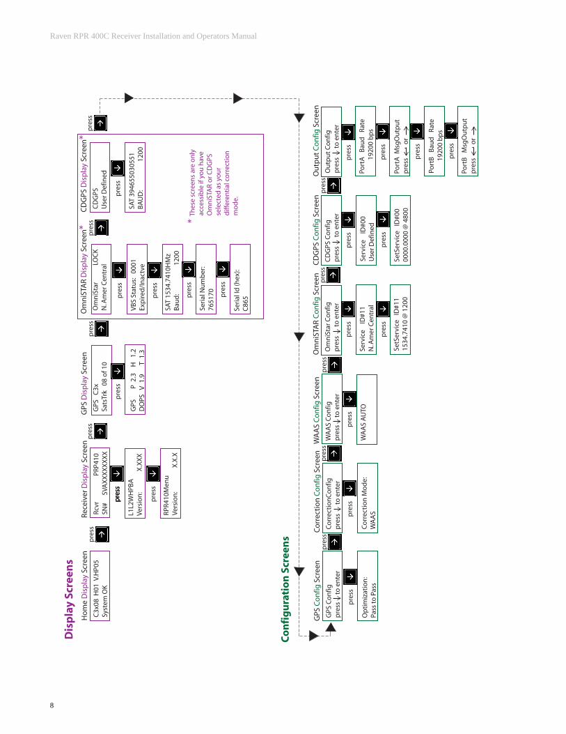
Operation The following are different screens and settings used by the front panel display.
Home Display ScreenRaven recommends that you use this screen during normal receiver operation.
Note: You can return to the Home screen anytime by pressing the and
arrow keys at the same time.
If the receiver is operating under normal operation without warnings, the front panel display will show:
The following is a list of display characters and their description:
Character(s) Description
D Displays differential mode. D=Differential, Blank=GPS only
3 Type of position solution (None, 2 Dimensional, 3 Dimensional)
08 Number of satellites use in position solution
H01 Horizontal Dilution of Precision (HDOP)
WAAS Current source of differential corrections with its associated age of data. WAAS=WAAS, CGPS=Canadian GPS, VBS = OmniStar
Status OK The second line is reserved for warning messages (OK, Poor SV Tracking, High AOD, High GDOP, High HDOP, No Diff Corrs, Hgt Constrained, No Pos Solution, Antenna Fault)

Raven RPR 400C Receiver Installation and Operators Manual
1 0
Receiver Display ScreenThis screen displays the receiver model, serial number, firmware version, and receiver options.
The following example displays the receiver model, serial number, and firmware
version. From the Home screen, press the key to show your settings:
Pressing the key will display all options currently installed:
Pressing the key will display more options currently installed:

Manual # 016-0171-038 Rev A 03/06
1 1
GPS Display ScreenFrom the Home screen, press the key until you get to the GPS Display screen:
Pressing the key will display the PDOP, HDOP, VDOP, or TDOP:
The term ‘DOP’ (Dilution of Precision) is an estimation of error cause by the geometry created by the position of the satellites used in the GPS solution. Smaller values denote better accuracy. A value of 9.9 is displayed when there are not enough satellites being tracked to provide a usable GPS solution.
OmniSTAR Display ScreenIf you have OmniSTAR selected as your differential correction mode, the OmniSTAR display screen will be available. You can access it by pressing the
DOP Definition
H (HDOP) Horizontal (East/West)
V (VDOP) Vertical (North/South)
T (TDOP) Time
P (PDOP) Position

Raven RPR 400C Receiver Installation and Operators Manual
1 2
key until you get to it:
Note: Do not confuse this screen with the CDGPS Configuration screen. Display screens are for viewing the settings, Configuration screens are for changing the settings.
Pressing the key will display the status of your OmniSTAR VBS subscription:
Press key again to display the satellite frequency and baud rate:

Manual # 016-0171-038 Rev A 03/06
1 3
Pressing the key again will display your OmniSTAR serial number:
Press the key again to display the OmniSTAR Service ID number:

Raven RPR 400C Receiver Installation and Operators Manual
1 4
CDGPS Display ScreenIf you have CDGPS selected as your differential correction mode, the
CDGPS display screen will be available. You can access it by pressing the key until you get to it:
Note: Do not confuse this screen with the CDGPS Configuration screen.
Pressing the key will display the satellite frequency number and baud rate:

Manual # 016-0171-038 Rev A 03/06
1 5
C H A P T E R
C O N F I G U R A T I O N S
GPS Configuration Menu
To get to the GPS Configuration screen, press the key until you get to the GPS Configuration screen:
To adjust the swathing performance, press the key to get to this screen:

Raven RPR 400C Receiver Installation and Operators Manual
1 6
Press the key to begin data entry. The current optimization mode will begin
to blink. Use the and arrow keys to change the setting, if needed,
then press the key when entry is complete.
Correction Configuration Menu
To get to the Correction Configuration screen, press the key until you get to the Correction Configuration screen:
To get to the Correction Mode screen, press the key:
Optimization Setting Definition
Pass to Pass Uses a filter to improve performance for long straight paths.Note: Performance may be slightly degraded when there are many turns in the path. The filter is ideal for field applications in which pass to pass accuracy is primarily needed.
None Does not use the ‘Pass to Pass’ mode filter.

Manual # 016-0171-038 Rev A 03/06
1 7
Press the key to begin data entry. The current correction mode setting will
begin to blink. Use the and arrow keys to change the setting, then
press the key when entry is complete.
The following table lists the possible differential correction modes:
Type Description
WAAS Wide Area Augmentation System
CDGPS Canadian DGPS
VBS OmniStar VBS
CMR N/A
RTCM N/A
RTCA N/A
None No differential correction
Raven RPR 400C Receiver Installation and Operators Manual
1 8
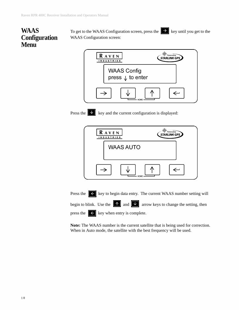
WAAS Configuration Menu
To get to the WAAS Configuration screen, press the key until you get to the WAAS Configuration screen:
Press the key and the current configuration is displayed:
Press the key to begin data entry. The current WAAS number setting will
begin to blink. Use the and arrow keys to change the setting, then
press the key when entry is complete.
Note: The WAAS number is the current satellite that is being used for correction.When in Auto mode, the satellite with the best frequency will be used.

Manual # 016-0171-038 Rev A 03/06
1 9
OmniSTAR Configuration Menu
The following screens are provided to aid in activating your OmniSTAR DGPS subscription service. Refer to the OmniSTAR subscription card included with your receiver for detailed information on how to activate your satellite differential signal.
To get to the OmniStar Configuration screen, press the key until you get to the OmniSTAR Configuration screen:
The Service ID screen is used to select the correct OmniSTAR satellite for your
area. Press the key and the current Service ID number and region setting is displayed:
Press the key to begin data entry. The current Service ID region setting will
begin to blink. Use the and arrow keys to change the setting, then
press the key when entry is complete.
Raven RPR 400C Receiver Installation and Operators Manual
2 0
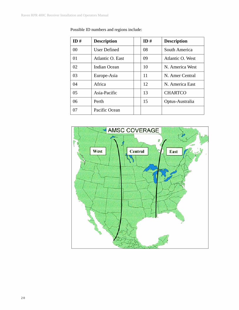
Possible ID numbers and regions include:
ID # Description ID # Description
00 User Defined 08 South America
01 Atlantic O. East 09 Atlantic O. West
02 Indian Ocean 10 N. America West
03 Europe-Asia 11 N. Amer Central
04 Africa 12 N. America East
05 Asia-Pacific 13 CHARTCO
06 Perth 15 Optus-Australia
07 Pacific Ocean

Manual # 016-0171-038 Rev A 03/06
2 1
Press the key again and the current SetService ID number is displayed. This screen can be used to enter a satellite frequency (e.g., 1554.4970 MHz) and symbol rate (e.g., 2438) supplied by OmniSTAR for your Service ID configuration:
Press the key to begin data entry. The current SetService ID number will
begin to blink. Use the and arrow keys to change the setting, then
press the key when entry is complete. The baud rate will begin to blink.
Use the and arrow keys to change the setting, then press the
key when entry is complete
Note: Use the key to scroll to different numbers in the SetService ID number.
Important: This operation is not normally used.

Raven RPR 400C Receiver Installation and Operators Manual
2 2
CDGPS Configuration Menu
To get to the CDGPS Configuration screen, press the key until you get to the CDGPS Configuration screen:
Press the key and the current Service ID is displayed:
Press the key to begin data entry. The current Service ID number will begin
to blink. Use the and arrow keys to change the setting, then press the
key when entry is complete.

Manual # 016-0171-038 Rev A 03/06
2 3
Press the key again and the current SetService ID is displayed:
Press the key to begin data entry. The current SetService ID number will
begin to blink. Use the and arrow keys to change the setting, then
press the key when entry is complete and the rate will blink.
Use the and arrow keys to change the setting, then press the
key when entry is complete.
Note: Use the key to scroll to different numbers.
Output Configuration Menu
To get to the Output Configuration screen, press the key until you get to the Output Configuration screen:
Raven RPR 400C Receiver Installation and Operators Manual
2 4
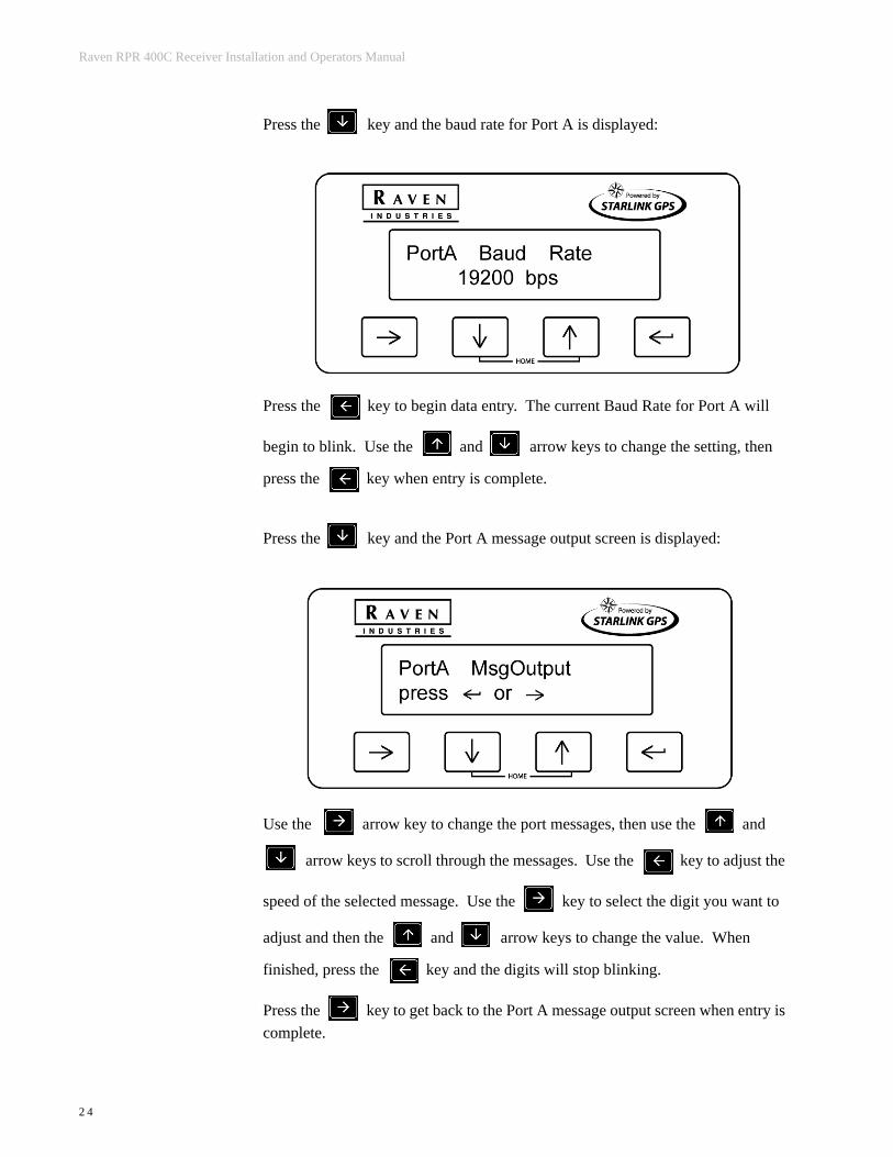
Press the key and the baud rate for Port A is displayed:
Press the key to begin data entry. The current Baud Rate for Port A will
begin to blink. Use the and arrow keys to change the setting, then
press the key when entry is complete.
Press the key and the Port A message output screen is displayed:
Use the arrow key to change the port messages, then use the and
arrow keys to scroll through the messages. Use the key to adjust the
speed of the selected message. Use the key to select the digit you want to
adjust and then the and arrow keys to change the value. When
finished, press the key and the digits will stop blinking.
Press the key to get back to the Port A message output screen when entry is complete.

Manual # 016-0171-038 Rev A 03/06
2 5
Note: An interval of 0.0 sec disables output of the selected messages on Port A.
The table below lists the optional interval rates:
To select the Baud Rate for Port B, press the button:
Press the key to begin data entry. The current Baud Rate for Port B will
begin to blink. Use the and arrow keys to change the setting, then
press the key when entry is complete.
Press the key and the Port B message output screen is displayed:
Programmed Interval of NMEA message
Output frequency (number of updates per second)
0.0 OFF
0.1 sec 10 Hz
0.2 sec 5 Hz
0.5 sec 2 Hz
1.0 sec 1 Hz

Raven RPR 400C Receiver Installation and Operators Manual
2 6
Use the arrow key to change the port messages, then use the and
arrow keys to scroll through the messages. Use the key to adjust the
speed of the selected message. Use the key to select the digit you want to
adjust and then the and arrow keys to change the value. When
finished, press the key and the digits will stop blinking.
Press the key to get back to the Port B message output screen when entry is complete.
Note: An interval of 0.0 sec disables output of the selected message on Port B. See the table under Port A for message and interval options.

Manual # 016-0171-038 Rev A 03/06
2 7
C H A P T E R
TRO U B L E S H O O T I N G
Before troubleshooting, attempt to isolate problems into one of these categories:
• Receiver• Antenna (including cables)• Power• Transmitting Site• Serial Communications (receiver or peripheral device)
Checking the Installation
Monitor the effects of the GPS receiver performance as each device on the vehicle is powered on. If the receiver stops operating properly when a device is powered on, that device is causing interference and the antenna location may need to be changed. For example, if running the engine causes interference, then ignition noise or alternator noise is interfering with signal reception. Move the antenna further away from the engine.
Receiver Normally only 5 GPS satellites are required for good accuracy. View the Front Panel Display Home Screen and check the number of satellites being tracked. Also look for the ‘D’, indicating a differentially corrected position.
Antenna Check the connections between the antenna and receiver. Verify the connectors and cable are in good condition. An ohmmeter can be used to determine if the antenna cable is open or shorted.
Important: Make sure that the antenna is mounted so that it has a clear view of the sky and is as far away from electrical noise sources as possible.

Raven RPR 400C Receiver Installation and Operators Manual
2 8
Power The front panel display should remain lit while power is applied.
Transmitting If the receiver is operating in WAAS mode, make sure the proper PRN is selected (e.g., - WAAS #122). WAAS status information is available on the Internet at http://www.waasperformance.raytheon.com/sis/sis.html. If the receiver is in OmniSTAR mode, verify the frequency of the satellites.
Receiver Specifications
Position Accuracy Chart:
Position Accuracy See chart below Operating Temp. -40 to +65 C
Timing Accuracy N/A Position Upgrades 20 solutions/sec
Num. of Channels 24 Max. Velocity 1000 Knots
Frequency Range 283.5-3250.0 kHz Rel. Humidity 95% non-condens.
Tuning Resolution < 1 Hz Altitude 60,000 feet
Min. Signal Strength
5 uV @ 1000 bps Dimensions 8.3” L x 5.7” W x 2.1” H
Dynamic Range > 100 dB Weight 20 ounces
Adj. Channel Rej. 50 dB at 1 KHz Antenna Weight < 1.3 pounds
Cold Start 6 min. typical, 15 min. max.
Antenna Diam. 7.5 inches
Warm Start 40 seconds Input Voltage 8-18 VDC
Reacquisition 1 second Power Consump. < 34 W @ 12VDC
Acceleration 2G Current 400 mA @ 12VDC
Connectors/Ports 2 RS-232 I/O
Differential Source Direction Accuracy
WAAS Horizontal RMS <1 m (40 in)
CDGPS Horizontal RMS <0.8 m (35 in)
OmniStar VBS Horizontal RMS <1.2 m (50 in)
Manual # 016-0171-038 Rev A 03/06
2 9
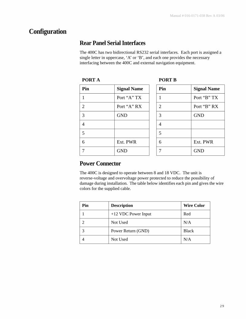
ConfigurationRear Panel Serial InterfacesThe 400C has two bidirectional RS232 serial interfaces. Each port is assigned a single letter in uppercase, ‘A’ or ‘B’, and each one provides the necessary interfacing between the 400C and external navigation equipment.
Power ConnectorThe 400C is designed to operate between 8 and 18 VDC. The unit is reverse-voltage and overvoltage power protected to reduce the possibility of damage during installation. The table below identifies each pin and gives the wire colors for the supplied cable.
PORT A PORT B
Pin Signal Name Pin Signal Name
1 Port “A” TX 1 Port “B” TX
2 Port “A” RX 2 Port “B” RX
3 GND 3 GND
4 4
5 5
6 Ext. PWR 6 Ext. PWR
7 GND 7 GND
Pin Description Wire Color
1 +12 VDC Power Input Red
2 Not Used N/A
3 Power Return (GND) Black
4 Not Used N/A

Raven RPR 400C Receiver Installation and Operators Manual
3 0
Notes:

Manual # 016-0171-038 Rev A 03/06
3 1
C H A P T E R
G L O B A L P O S I T I O N I N G S Y S T E M (GPS)
GPS is a satellite-based global navigation system created and operated by the United States Department of Defense (DOD). Originally intended solely to enhance military defense capabilities, GPS capabilities have expanded to provide highly accurate position and timing information for many civilian applications.
An in-depth study of GPS is required to fully understand it, but not to see how it works or appreciate what it can do. Simply stated, twenty-four satellites in six orbital paths circle the earth twice each day at an inclination angle of approximately 55 degrees to the equator. This constellation of satellites continuously transmit coded positional and timing information at high frequencies in the 1500 Megahertz range. GPS receivers with antennas located in a position to clearly view the satellites pick up these signals and use the coded information to calculate a position in an earth coordinate system.
GPS is the navigation system of choice for today and many years to come. While GPS is clearly the most accurate worldwide all-weather navigation system yet developed, it still can exhibit significant errors. GPS receivers determine position by calculating the time it takes for the radio signals transmitted from each satellite to reach earth. It’s that old “Distance = Rate x Time” equation. Radio waves travel at the speed of light (Rate). Time is determined using an ingenious code matching technique within the GPS receiver. With time determined, and the fact that the satellite’s position is reported in each code navigation message, by using a little trigonometry, the receiver can determine its location on earth.
Position accuracy depends on the receiver’s ability to correctly calculate the time it takes for each satellite signal to travel to earth. This is where the problem lies. There are primarily four sources of errors which can affect the receiver’s calculation. These errors consist of:• Ionospheric and tropospheric delays on the radio signal• Signal multi-path• Receiver clock biases• Orbital satellite (ephemeris) position errors

Raven RPR 400C Receiver Installation and Operators Manual
3 2
Notes:
Manual # 016-0171-038 Rev A 03/06
3 3
C H A P T E R
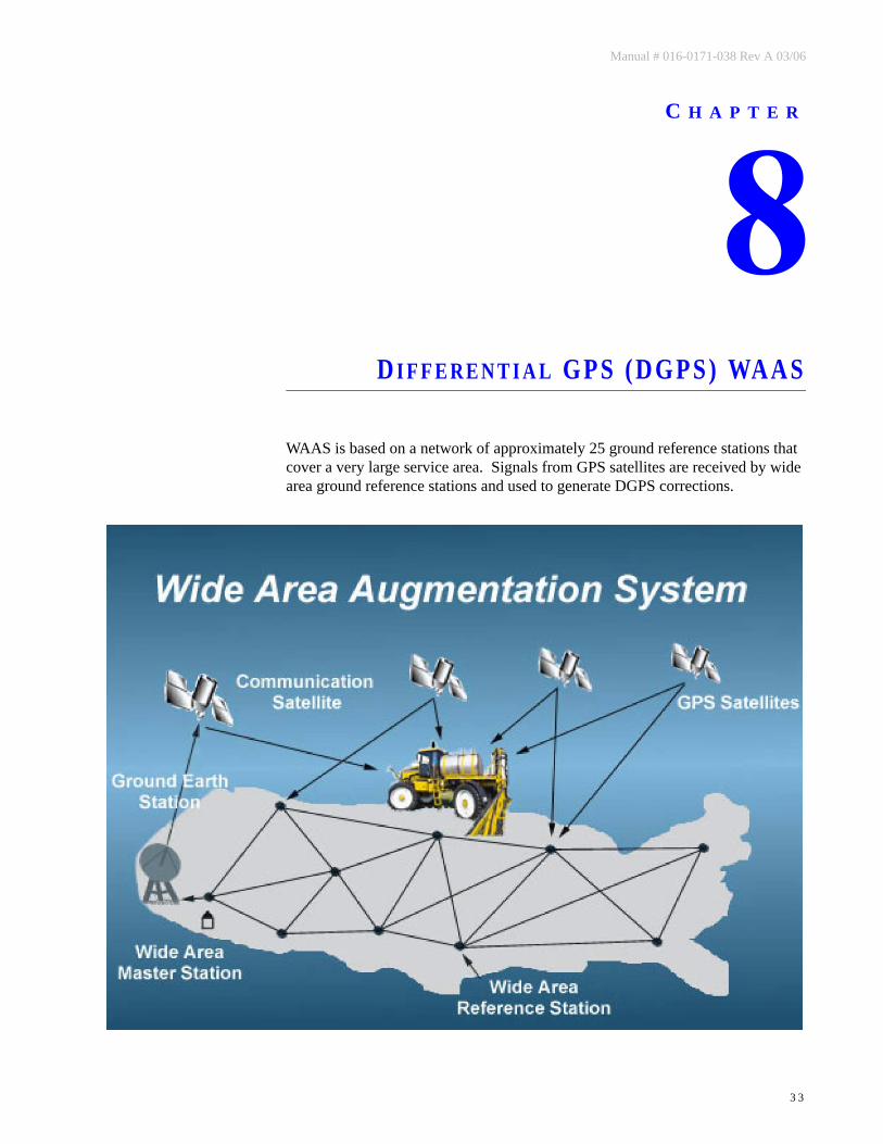
D I F F E R E N T I A L GPS (DGPS) WAAS
WAAS is based on a network of approximately 25 ground reference stations that cover a very large service area. Signals from GPS satellites are received by wide area ground reference stations and used to generate DGPS corrections.

Raven RPR 400C Receiver Installation and Operators Manual
3 4
Notes:
Manual # 016-0171-038 Rev A 03/06
3 5
C H A P T E R
DGPS O M N I STAR
The OmniSTAR system is a full-time differential GPS broadcast system, delivering corrections to the world’s major land masses from a worldwide array of reference sites. Data from these reference sites flows to Network Control Centers (NCC’s) where the RTCM corrections are decoded, checked, and repackaged in a highly efficient format for broadcast. The data is then upconverted for transmission to communication satellites which broadcast over geographical areas. Communication links with each reference site include a dial-up line to serve as backup to leased lines to allow control of the receivers.
The satellite broadcast is received at the user’s location, demodulated, and passed to a processor that reformats the data into corrections for use in the 400C receiver. In OmniSTAR, atmospheric corrections are applied to the data from multiple sites which are then combined to provide an optimal correction for the user’s location. These corrections, recast in RTCM SC-104 format, are used by the 400C receiver for maximum accuracy.

Raven RPR 400C Receiver Installation and Operators Manual
3 6
How it works:1. GPS Satellites2. Multiple OmniSTAR GPS reference sites3. Differential GPS corrections send vial lease line to4. NCC’s where data corrections are checked and repackaged for uplink
to communication satellites5. Geostationary communications satellite6. Satellite broadcast footprint - OmniSTAR user area7. Correction data are received and applied real-time

Manual # 016-0171-038 Rev A 03/06
3 7
C H A P T E R
NMEA M E S S A G E S
The 400C receiver can be used to communicate with other electronic devices including Raven’s Guidance Lightbar. A communication protocol (set of rules) known as the NMEA-0183 standard has been established by the National Marine Electronics Association. The NMEA-0183 standard contains numerous message formats such as the ones described below, which the 400C receiver uses to communicate with other devices.
400C NMEA Messages
GGA Global Positioning System Fix Data
RMC Recommended Minimum Specific GPS/Transit Data
VTG Course Over Ground and Ground Speed
ZDA Time and Date

Raven RPR 400C Receiver Installation and Operators Manual
3 8
Notes:
Manual # 016-0171-038 Rev A 03/06
3 9
C H A P T E R
S A M P L E M E S S A G E ST R U C T U R E
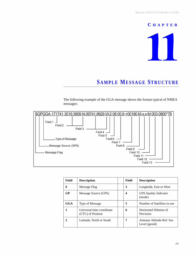
The following example of the GGA message shows the format typical of NMEA messages:
Field Description Field Description
$ Message Flag 3 Longitude, East or West
GP Message Source (GPS) 4 GPS Quality Indicator (mode)
GGA Type of Message 5 Number of Satellites in use
1 Universal time coordinate (UTC) of Position
6 Horizontal Dilution of Precision
2 Latitude, North or South 7 Antenna Altitude Ref: Sea Level (geoid)

Raven RPR 400C Receiver Installation and Operators Manual
4 0
Field Description Field Description
8 Units of Antenna Altitude (meters in example)
11 Age of Differential Data, seconds
9 Geoidal Separation 12 Reference Station ID
10 Units of Geoidal Separation (meters in example)
13 Checksum

Manual # 016-0171-038 Rev A 03/06
4 1
C H A P T E R
H A R D W A R E
Menu Versions Information in this document is subject to change without notice and does not represent a commitment on the part of Raven Industries. The RPR 400C Receiver is a new hardware product that is continually undergoing improvement. The information contained within this manual is believed to be true and correct at the time of this publication.
The changes made regarding the RPR 400C will be reflected in the menu interface. The menu version can be compared using the directions described in the Receiver Display Screen section. This manual was last updated for the RPR 400C Menu version 1.11.


RAVEN INDUSTRIES
LIMITED WARRANTY
WHAT IS COVERED?
This warranty covers all defects in workmanship or materials in your RavenFlow Control Product under normal use, maintenance, and service.
HOW LONG IS THE COVERAGE PERIOD?
This warranty coverage runs for 12 months from the purchase date of yourRaven Flow Control Product. This warranty coverage applies only to theoriginal owner and is not transferrable.
HOW CAN YOU GET SERVICE?
Bring the defective part, and proof of date of purchase, to your local dealer.If your dealer agrees with the warranty claim, he will send the part, and proofof purchase to his distributor or to Raven for final approval.
WHAT WILL RAVEN INDUSTRIES DO?
When our inspection proves the warranty claim, we will, at our option, repairor replace the defective part and pay for return freight.
WHAT DOES THIS WARRANTY NOT COVER?
Raven Industries will not assume any expense or liability for repairs madeoutside our plant without written consent. We are not responsible for damageto any associated equipment or product and will not be liable for loss of profitor other special damages. The obligation of this warranty is in lieu of all otherwarranties, expressed or implied, and no person is authorized to assume forus any liability. Damages caused by normal wear and tear, mis-use, abuse,neglect, accident, or improper installation and maintenance are not coveredby this warranty.

Raven Industries Toll Free 800-243-5435Flow Controls Division Fax 605-331-0426P.O. Box 5107 www.ravenprecision.comSioux Falls, SD 57117-5107 [email protected]
RPR 400C G
PS An
tenn
a & Receiver In
stallation
& O
perato
rs Man
ual (P/N
016-0171-038 Rev A 03/06)