installation & maintenance manual pp burner
TRANSCRIPT

+44 (0) 1905 775 783 www.comtherm.co.uk [email protected]
Installation & Maintenance Manual
PP Burner
Burners, Heaters & Combustion Systems

PP Burner Instruction Manual
Page.1 .............................................General Specification
Page.2 .............................................General Description
Page.3 .............................................Installation
Page.4 .............................................Installation
Page.5 .............................................Installation
Page.6 .............................................Initial Light Up (Commissioning guidance)
Page.7 .............................................Initial Light Up (Commissioning guidance)
Page.8 .............................................Initial Light Up (Commissioning guidance)
Page.9 .............................................Initial Light Up (Commissioning guidance)
Page.10 ...........................................Fault Finding Guide
Page.11 ............................................Fault Finding Guide
Page.12 ............................................Fault Finding Guide
Page.13 ............................................Fault Finding Guide
Page.14 ............................................Fault Finding Guide
Page.16 ............................................Parts List (Key)
Page.17 ............................................Suggested Service Program
Page.18 ............................................Suggested Service Program
Page.19 ............................................Burner Service program
Page.20 ............................................Burner Commissioning Record
Page.21 ............................................Additional Commissioning Notes
Index
Comtherm LtdInstallation & Maintenance Manual
Burners, Heaters & Combustion Systems

The 'PP' series of gas burners are pre-packaged fan assisted units designed to suit virtually all types of low temperature gas fired application; typical applications include the firing of box ovens, industrial dryers and air heaters. The PP burners utilise the well proven Comtherm PH and PHC burner head and combustion system. The burner system produces a wide flame spread and therefore relatively short flame; this feature makes the burner ideal for applications were chamber length is restricted. The 'PP' burners have been designed with ease of maintenance and installation a top priority, all parts of the burner including the gas manifold and combustion head can be removed without unbolting the burner off the mounting flange. For ease of maintenance and service the spark plug and flame sensor are externally mounted. A heat resistant peep-sight is fitted in the casing of all burners allowing visual inspection of the flame during operation. The nozzle mix design of the burner and the progressive air mixing feature of the combustion head ensure that burners can operate with high turn down capability; turndown ratios up to 40:1 are possible depending on burner applications and selection.
THREE HEAT INPUT RATES The PP burner is manufactured in three basic gas manifold and air plate designs making possible a burner range with heat input concentrations of 60kW, 290kW and 580kW per 300mm length of burner gas manifold. The flame length produced by the PP burner is obviously shorter than that produced by conventional burners and does depend on burner setting, combustion chamber conditions and application. Nominal flame lengths that can be achieved for heat inputs of 60kW, 290kW and 580kW per 300mm length of burner gas manifold are 300mm, 700mm and 1000mm respectively.
All valve assemblies on the burners are sized to suit an inlet gas pressure of 17.5 mbar (natural gas) or 30mbar (LP gases) unless otherwise specified. Burners can be supplied to suit other gas types and supply pressures.
Combustion air Pressure Drop across burner air wings; PP 200 Pascals
The nozzle mix design of the burner and the progressive air mixing feature of the combustion head ensure that burners can operate with high turn down capability; turndown ratios up to 40:1 are possible depending on burner applications and selection. The PP burner range is designed to always operate with approximately 30% excess combustion air. For high - low and modulating gas only burners
General Specification
Comtherm LtdInstallation & Maintenance ManualPage 01
Burners, Heaters & Combustion Systems
The burner consists of a gas manifold assembly having fuel and air jets designed to produce effective mixing of the fuel and combustion air hence providing good flame stability.
The manifold assembly is fitted with integral ignition and flame sensor facilities. The unit comes complete with all the valves and controls required; forming a fully packed, safe burner assembly.
The valves and controls are pre-piped and mounted on the burner side plate, as illustrated diagrammatically on page M4. Pressure test points are fitted between valves where necessary.
The physical arrangement of the burner is shown in diagram form on page M3 (where applicable).
All the electrical equipment on the unit is pre-wired to a terminal enclosure on the assembly, as detailed in the burner wiring diagram M5.
The electrical operation of the burner is as follows:When the electrical supply is switched on to the burner and all the control circuits are closed, the burner light up sequence is initiated.
The burner flame safety sequence control unit (unit A1) receives the electrical start signal and begins to cycle through an air pre-purge and light up sequence.
The air pre-purge is for a specified, preset time and allows for dilution of any fuel leakage; to safeguard against the possibility of explosive fuel/air mixture being present in the burner duct when the ignition is energized. After the completion of the pre-purge, the ignition and flame proving period take place.
When the flame signal is proven, the burner sequence control remains in the operating position until any of the control circuit interlocks are broken or a flame failure (lockout) condition occurs.
Complete details of the burner light-up sequence including the flame safety control unit (item A1) will be found in the component data sheet, enclosed.
For details on installation and commissioning, refer to pages 3-9.
NOTE: - See pages 16 for key to items referred to throughout this manual. Refer to documents M1, M3, M4, M5, M9 sent with your contract for specific component manufacturers used on this equipment.
General Description
Comtherm LtdInstallation & Maintenance Manual Page 02
Burners, Heaters & Combustion Systems

Before proceeding with the installation of the burner, inspect the burner for any physical damage that may have occurred during transit, storage or off-loading. Any damage should be reported immediately.
The pipe work or gas valves on the burner should not be used for lifting under any circumstances, as this tends to pull fittings loose or damage valves, causing leaks during later operation.
Mount the burner in the firing position, making sure that adequate space is allowed around the burner for ventilation and that the combustion air inlet is not blocked. Ensure that an adequate fresh air supply is available for combustion and general ventilation.
Situations where gas from valve and pipe work leaks can collect and form pockets of combustible gas/air must be avoided.
Ensure that adequate space is allowed around the burner for easy access to all burner components, pressure switches, control operators etc.
The burner should be securely fixed and the transmission of vibration and heat should be minimised.
GAS SUPPLY:
Gas piping to the burner should be of sufficient size to provide the correct gas pressure at the burner valve assembly inlet (see specification in document M1). If in any doubt concerning the size and design of the gas supply pipe work, consult the gas supply company.
The pressure loss in the gas supply pipe work should be such that the following pipeline velocities are not exceeded:
Unfiltered supply 20M/s (65.6ft.sec)
Filtered supply (250microns) 45M/s (148ft.sec)
The above stated velocities are based on the avoidance of excessive noise pollution and erosion.
For low-pressure supplies up to 25 mbar (10 w.c), the pressure drop between the meter and the burner inlet should normally not exceed 1mbar (0.4 w.c). For high-pressure supplies, this pressure drop should not exceed 10% of the available gas pressure.
Installation
Comtherm LtdInstallation & Maintenance ManualPage 03
Burners, Heaters & Combustion Systems

A manual shut off valve followed by a union or flanged joint should be incorporated in the Gas supply pipe adjacent to the burner, this valve permits isolation of the supply and removal of the burner assembly for maintenance purposes.
The manual shut off valve should be easily accessible.
Do not use the burner valve assembly to support the gas supply pipe work. Suitable brackets or hangers should be used for this purpose.
Before connecting the gas supply check that the available gas pressure is correct (see specification in documentt M1).
Check that the gas supply system has been designed and installed to ensure that during fault conditions, pressures in excess of the maximum design rating of the equipment can not be reached.
If the burner is installed in a confined space consideration should be taken for the fitting of a vent pipe to the breather holes of governors.
Vents from governors must not be manifolded and should terminate in a safe place, preferably above roof level.
Any additional vent pipes that are required will be shown in document M4.
The gas supply pipe will be full of air and will require purging.
This purging should only be carried out by a suitably qualified gas engineer.
With regard to the soundness (leak) testing and purging of the supply pipe work ensure that a certificate exists stating that this work has been completed in accordance with technical publications EN 746-2.
After completion of the installation work, the procedure for testing for gas leaks on the burner detailed in the manual section pages 10-15, should be completed and any leaks repaired.
The burner should be left with the manual shut off valve (item V1) in the closed position until the plant is commissioned by a suitably qualified gas engineer.
Installation (Continued)
Comtherm LtdInstallation & Maintenance Manual Page 04
Burners, Heaters & Combustion Systems
Burners can be supplied to suit almost all types of electrical power supply; including all common industrial three phase (50 or 60Hz) power supplies and with 110/120v or 220/240v control circuits.
Burners to suit other electrical supply voltages can be supplied specially to suit specific application requirements.
All wiring on the burner should comply with the requirements of the local electrical codes of practice.
All conduits should be kept clear of heat zones.
Local means of electrical isolation should be installed close to the burner.
Ensure that the electrical voltage does not vary from the specified by more than 6%.
High temperature wire (tri-rated or better) should be used for all electrical connections.
The electrical connections to the burner shown on diagram M5 should be strictly adhered to.
Gas pipe work should not be used as an electrical earth.
Installation (Continued)
Comtherm LtdInstallation & Maintenance ManualPage 05
Burners, Heaters & Combustion Systems
.

PLEASE NOTE:Without exception, burners should only be commissioned by suitably qualifiedpersonnel. The following notes are intended as guidance and in no way negate theneed for the equipment to be commissioned by suitably qualified personnel.
1. Examine the burner for physical damage.
2. Close all manual fuel valves.
3. Check that the electrical supply is switched off.
4. Check all electrical connections to ensure that the combustion air pressure switch (item P1)and the safety shut off valve (item S1) are wired to the correct terminals in the burnersafety control unit (see electrical diagram in document M5)
5. Check the incoming gas pressure (at V1) and verify that the inlet gas pressure is asspecified (see page M1).Generally speaking, the inlet gas pressure, without the burneroperating, will be somewhat higher than when the burner is in operation.
6. Ensure that the burner on/off switch is in the position.
7. Switch the electrical supply on.
8. Check for gas leaks on the burner as follows:(a) Close the manual valve V1 and pilot manual valve V6.(b) Vent burner pipe work downstream of V1 by opening a suitably positioned testnipple.(c) Use a manometer test pressure downstream of V1 for 1.5 minutes. If no pressurebuilds up, valve V1 is not leaking.(d) Open valve V1.(e) Check for external leakage using a soap solution or gas detector onpipe work and valves, rectifying any leaks before proceeding.(f) Put temporary electrical supply onto valve S1.This will pressurise the spacebetween S1 and S2. Open the test point downstream of S2 and connect themanometer (valve V2 must be closed); if no pressure builds up within 1.5 minutes thenvalve S2 is sound.
Initial Light Up (Commissioning)
Comtherm Ltd Installation & Maintenance Manual Page 06
Burners, Heaters & Combustion Systems

(g) Disconnect the electrical supply to valve S1 and vent the spacebetween valve S1 and S2, using the pressure test nipple. Using themanometer, check that no pressure builds up between the two valves; if no pressure
is detected then valve S1 is sound(h) Open pilot manual valve V6 and check by using the test nipple downstream of V1
that there is no pressure drop at this point. If no pressure drop is detected in 1.5minutes then valve S3 is not leaking.
(i) Finally, check downstream of V2 and V3 with soap solution or gas detector (withburner running).
In cases where burners are fitted with main multi-block / combination safety valveunits, the above procedure will vary; the valve should be energized to check fordownstream pipe leakages and de-energised followed by venting of downstreampipe space to check for valve seat leakages.
9. Release the spring pressure on the gas governor (item G2).
10. Set the combustion air pressure switch (item P1) 25% below the specified air pressurerequired.
11. Start the fan supplying the combustion air and ensure that the fan rotation direction iscorrect.
Check the running current of the motor and crosscheck this with the data on the Motor label.Ensure that the motor overload protection is correctly set.
12. Ensure that valves V2 and V6 are closed.
13. Check that all pressure switches associated with the burner are in the correct position.Note that the burner combustion air pressure switch (item P1) should be in theposition and should only switch over after the combustion air fan has started
14. Check that all pressure switches associated with the burner are in the position callingfor and switch the burner on. It may be necessary to reset the burner lockout fault button.
Initial Light Up (Commissioning)
Comtherm LtdInstallation & Maintenance ManualPage 07
Burners, Heaters & Combustion Systems
15. Allow the flame safety control unit (item A1) to cycle through the start up sequence; checkthat the pressure switch (P1) has changed over from the `no to the air proved position.If it adjust the combustion air supply so as to provide satisfactory burner airpressure. Check that the ignition and pilot solenoid valves are electrically energised at thecorrect time and in the correct sequence. The burner flame safety control unit should thenlockout.
16. Open the manual pilot valve (item V6)
17. Fit Micro-ammeter into circuit with the flame sensor.
18. Reset the burner lockout button; the burner will cycle and the pilot flame should light. Itmay be necessary to start the light up sequence (reset) several times so as to remove airfrom the pilot line and to adjust the pilot flame to the correct size. Check the pilot flamesignal on the micro-ammeter.
19. Note that the burner will go to lockout after each attempt to light the pilot.
20. Half open the manual test valve (item V2). Reset the burner lockout button. The burnershould cycle and light up onto the main flame.
21. Slowly open up the manual test valve (item V2) to the full position and adjust the main gasgovernor (item G2) to produce the required flame size. With the burner on full fire(temperature control calling heat) check that the gas pressure at the nozzle is as specifiedfor the required thermal/fuel rating, this will be indicated on the burner data label andcan also be established from the nozzle flow graph included with this manual.
22. Check the main flame signal on the micro-ammeter.
23. Turn the combustion air pressure switch (item P1) upwards so that the burner shuts down.Note the adjustments in air pressure and reduce the switch setting by 25%.
24. Whilst the burner is operating remove the electrical connections from the flame sensor.Check that the burner flame safety control locks out immediately and that the gas supply isautomatically shut off.
25. Whilst the burner is operating, block the combustion air supply so that the pressure switchP1 switches to the position, checking that the burner shuts down.
Initial Light Up (Commissioning)
Comtherm LtdInstallation & Maintenance Manual Page 08
Burners, Heaters & Combustion Systems
26. Check the operation of all control and safety devices in the burner control circuits.In addition, ensure that the burner operates correctly. Make a note of all control settings.
27. The low fire setting of the burner should be made in line with the process requirementswhilst still maintaining a steady flame signal.
NOTE;-Once correctly commissioned the burner settings should only be altered by suitablyqualified personnel, and only when changes to the process requirements deem itnecessary. At no point should the settings of any safety device be altered to overcomechanges in process conditions without the burner again being fully commissioned in linewith those process conditions.
Initial Light Up (Commissioning)
Comtherm LtdInstallation & Maintenance ManualPage 09
Burners, Heaters & Combustion Systems

FIND FAULT POSSIBLE CAUSES SOLUTION
Burner light up sequence does not start
No electrical supply Check electrical supply at local isolator.Check the control fuse
Burner electrical control
condition
Check controls and switches in control circuitCheck all pressure switches and micro-switches
Airflow pressure switch not made
Check setting on switch, if this is correct check airflow
Low gas pressure switch not made
Check setting on switch if this is correct check the gas pressure
Start cycle begins but the burner locks out or shuts down before initiating the ignition sequence
Low combustion air pressure differential
Reset burner pressure switch (P1) If pressure switch P1 is set correctly open the air damper on the combustion air fanCheck that the combustion air fan motor is rotating in the correct directionCheck that the combustion air fan is running, if not check the overload or circuit breakers
Fault Finding Guide
Comtherm LtdInstallation & Maintenance Manual Page 10
Burners, Heaters & Combustion Systems

FIND FAULT POSSIBLE CAUSES SOLUTION
Pilot does not light No spark Check electrical supply to ignition transformerCheck electrical connection to spark plugCheck operation of ignition transformerCheck condition of spark plug and clean, reset or replace
No pilot gas Check manual valve is openCheck that pilot solenoid valve opensEnsure gas is available at burner
Not enough pilot gas Check pilot gas flow adjusterand pilot gas regulator
Pilot blown out Reduce process air flow if possibleIncrease pilot gas rate
Pilot lights but locks out when ignition de-energised
Pilot gas rate too low Adjust pilot gas rate
Pilot lights but the burner locks out before the main valves are energised
Flame sensor not detecting the flame
Or
Faulty sensor
Check sensor for damage or moistureClean flame sensorCheck flame sensor installation and positionReplace sensor
Fault Finding Guide
Comtherm LtdInstallation & Maintenance ManualPage 11
Burners, Heaters & Combustion Systems
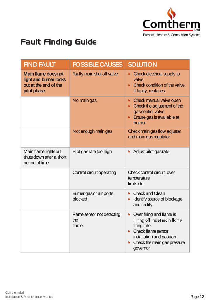
FIND FAULT POSSIBLE CAUSES SOLUTION
Main flame does not light and burner locks out at the end of the pilot phase
Faulty main shut off valve Check electrical supply to valveCheck condition of the valve, if faulty, replaces
No main gas Check manual valve openCheck the adjustment of the gas control valveEnsure gas is available at burner
Not enough main gas Check main gas flow adjuster and main gas regulator
Main flame lights but shuts down after a short period of time
Pilot gas rate too high Adjust pilot gas rate
Control circuit operating Check control circuit, over temperaturelimits etc.
Burner gas or air ports blocked
Check and CleanIdentify source of blockage and rectify
Flame sensor not detecting theflame
Over firing and flame is
firing rateCheck flame sensor installation and positionCheck the main gas pressure governor
Fault Finding Guide
Comtherm LtdInstallation & Maintenance Manual Page 12
Burners, Heaters & Combustion Systems
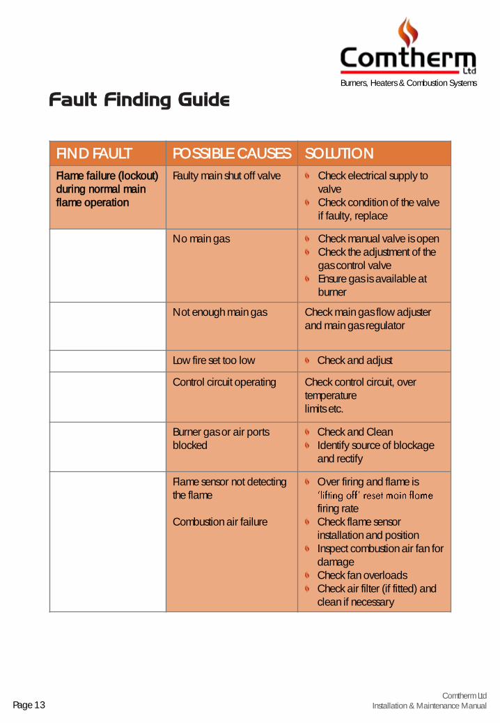
FIND FAULT POSSIBLE CAUSES SOLUTION
Flame failure (lockout) during normal main flame operation
Faulty main shut off valve Check electrical supply to valveCheck condition of the valve if faulty, replace
No main gas Check manual valve is openCheck the adjustment of the gas control valveEnsure gas is available at burner
Not enough main gas Check main gas flow adjuster and main gas regulator
Low fire set too low Check and adjust
Control circuit operating Check control circuit, over temperaturelimits etc.
Burner gas or air ports blocked
Check and CleanIdentify source of blockage and rectify
Flame sensor not detecting the flame
Combustion air failure
Over firing and flame is
firing rateCheck flame sensor installation and positionInspect combustion air fan for damageCheck fan overloadsCheck air filter (if fitted) and clean if necessary
Fault Finding Guide
Comtherm LtdInstallation & Maintenance ManualPage 13
Burners, Heaters & Combustion Systems

FIND FAULT POSSIBLE CAUSES SOLUTION
Flame failure (lockout) at low fire
Faulty low fire bypass valve(high low burners only)
Low fire flame set too lowCheck electrical supply to valveCheck condition of the valve if faulty, replace
Low fire flame set too low Check the adjustment of the gas control valveEnsure gas is available at burner
Too much air Check and reset air at high and low fire
Low fire air set too low (modulating gas and air burners only)
Check and adjust
Control circuit operating due to
Check control circuit, over temperature limits and low fire settings
Flame sensor not detectingFlame
Check flame sensor installation and position
Main flame too long Too much gas Check main gas pressure and resetCheck gas control valve and resetCheck fuel type
Combustion air set too low Check air dampers, linkages and air filter (where fitted)
Fault Finding Guide
Comtherm LtdInstallation & Maintenance Manual Page 14
Burners, Heaters & Combustion Systems

FIND FAULT POSSIBLE CAUSES SOLUTION
Red.Low process airflow. Reset air.
Main flame too long. Check the adjustment of the gas control valve.
Combustion air set too low. Check air dampers, linkages and air filter (where fitted).
Unit will not achieve temperature.
Too much process air. Check and reset air.
Burner input setting too low. Check and reset Burner.
Leakage of cold air into system.
Source and rectify.
Burner shuts down (see also sheets M8.1 to M8.4b).
Control circuit operating. Check control circuit, process airflow switch, over temperature limits and low fire settings.
Flame sensor not detecting the flame.
Check flame sensor installation and position.
Too much pressure in chamber.
Check Flue.
Unit Produces condensation.
Burner turned down too low.
Check the adjustment of the gas control valve.
Low process air volume. Check and reset air.
Fault Finding Guide
(Indirect Heaters)
Burners, Heaters & Combustion Systems
Page 15Comtherm Ltd
Installation & Maintenance Manual

Parts List (Key)
A1: Flame control unit A2: Flame electrode A3: U.V. flame sensor A4: Valve proving unit B1: Burner combustion head B2: Peep sight B3: Viewing window B4: Inspection plate C1: Burner fan contactor/overload C2: Process air fan contactor/overload E1: Ignition transformer E2: Ignition plug E3: Burner on-off switch E4: Low fire position micro switch E5: High fire position micro switch E6: Closed position indicator switch E7: Isolator E8: Terminal box E9: Purge timer ET: 24v Control transformer EB: Alarm Bell EFS: Exhaust flow switch FC: Control circuit fuse FB: Burner control fuse F1: Burner motor fuse F2: Process air fan fuse G1: Primary gas regulator (high pressure) G2: Main gas governor G3: Primary pilot gas governor (high pressure) G5: Over pressure slam shut valve G6: Pressure relief valve K1: Push button burner start K2: Push button burner stop K3: Push button lockout reset K4: Push button fault reset K5: Push button alarm mute K6: Push button valve proving fault reset K7: Push button Flame signal test L1: Indication light burner lockout L2: Indication light burner run L3: Indication light valve fault L4: Indication light power on L5: Indication light instruments on
L6: Indication light burner fan failureL7: Indication light burner fan run L9: indication light process fan run L10: indication light exhaust fan run MF: Burner fan M1: Burner fan motor M2: Burner fan impellor P1: Burner fan pressure switch P2: Process air pressure switch P3: Low gas pressure switch P4: High gas pressure switch P5: Valve proving pressure switch P8: Gas pressure gauge P9: Air pressure gauge R: Electrical relay S1: First safety shut off valve S2: Second safety shut off valve S3: First pilot/start gas solenoid valve S4: Second pilot/start gas solenoid valve S5: Vent valve (normal open) S6: Three way solenoid valve -burner air SM: Solenoid/governor multi-bloc valveTC: Control instrument TL: High limit thermostat or sensor T3: Valve positioner T4: Valve actuator T5: Control supply transformer V1: Manual inlet valve V2: Manual test valve V3: Gas filter V4: Vent cock V5: Gas control valve V6: Pilot manual gas valve V7: Pilot gas adjustment V8: Gauge cock V9: Air flow control valve V10: Gas flow adjustment V11: Air flow adjustment V12: Air filter V13: Oil filter V14: Oil control valve
V15: Gas orifice plate
Inclusion of this list does not imply that all items are included in the particular equipment to which this refers: refer to sheets M3 (if
applicable), M4 and M5 for details. Refer to recommended spares list for actual complete parts specification.
Burners, Heaters & Combustion Systems
Page 16
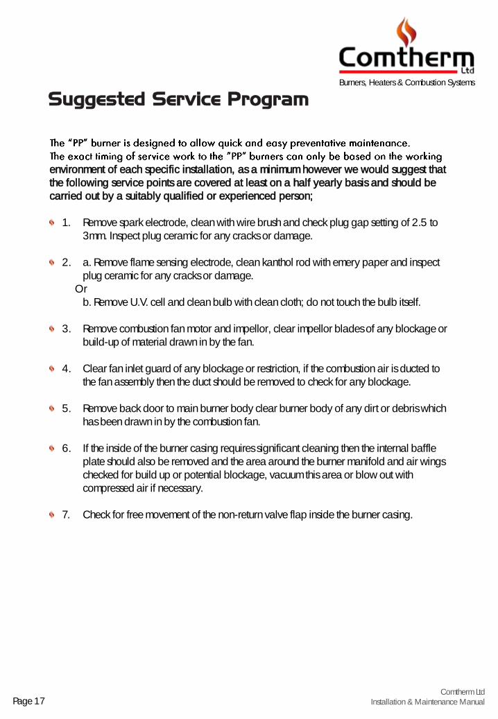
environment of each specific installation, as a minimum however we would suggest that the following service points are covered at least on a half yearly basis and should be carried out by a suitably qualified or experienced person;
1. Remove spark electrode, clean with wire brush and check plug gap setting of 2.5 to 3mm. Inspect plug ceramic for any cracks or damage.
2. a. Remove flame sensing electrode, clean kanthol rod with emery paper and inspect plug ceramic for any cracks or damage.
Or b. Remove U.V. cell and clean bulb with clean cloth; do not touch the bulb itself.
3. Remove combustion fan motor and impellor, clear impellor blades of any blockage or build-up of material drawn in by the fan.
4. Clear fan inlet guard of any blockage or restriction, if the combustion air is ducted to the fan assembly then the duct should be removed to check for any blockage.
5. Remove back door to main burner body clear burner body of any dirt or debris which has been drawn in by the combustion fan.
6. If the inside of the burner casing requires significant cleaning then the internal baffle plate should also be removed and the area around the burner manifold and air wings checked for build up or potential blockage, vacuum this area or blow out with compressed air if necessary.
7. Check for free movement of the non-return valve flap inside the burner casing.
Suggested Service ProgramBurners, Heaters & Combustion Systems
Page 17Comtherm Ltd
Installation & Maintenance Manual

8. A visual inspection of the front face of the burner manifold and air wings (inside the oven) should then be made, any extensive build-up of soot or other deposit should be cleaned off and the gas and air jets of the manifold checked for blockage.
9. If access to the inside of the oven is not possible then the burner manifold complete with air wings can be withdrawn through the back of the burner by simply unbolting the gas manifold and the 6mm head retaining screws inside the casing. The valve assembly union prior to the burner casing would need to be undone in order to withdraw the head.
At the time of the above inspection any burner air wings found to be significantly damaged / split / deformed should be replaced. Small cracks and fishers or slight distortion in the wings would not be detrimental to the operation of the burner.
This down time with the burner should also be used to check the integrity and correct operation of safety pressure switches and solenoids.
Suggested Service ProgramBurners, Heaters & Combustion Systems
Page 18Comtherm LtdInstallation & Maintenance Manual

Date of Service Service Company Engineer Name Date of Next Service
Burner Service Program
Burners, Heaters & Combustion Systems
Page 19Comtherm Ltd
Installation & Maintenance Manual
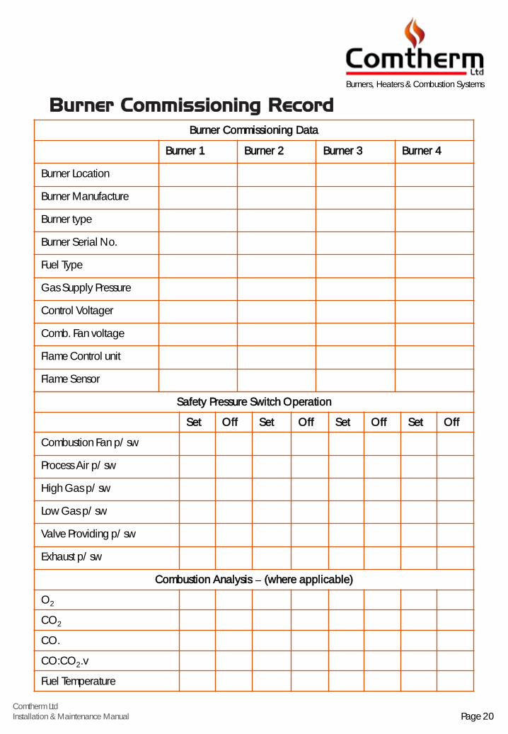
Burner Commissioning Data
Burner 1 Burner 2 Burner 3 Burner 4
Burner Location
Burner Manufacture
Burner type
Burner Serial No.
Fuel Type
Gas Supply Pressure
Control Voltager
Comb. Fan voltage
Flame Control unit
Flame Sensor
Burner Commissioning Record
Safety Pressure Switch Operation
Set Off Set Off Set Off Set Off
Combustion Fan p/sw
Process Air p/sw
High Gas p/sw
Low Gas p/sw
Valve Providing p/sw
Exhaust p/sw
Combustion Analysis (where applicable)
O2
CO2
CO.
CO:CO2.v
Fuel Temperature
Burners, Heaters & Combustion Systems
Page 20Comtherm LtdInstallation & Maintenance Manual

Additional Commissioning NotesBurners, Heaters & Combustion Systems
Page 21Comtherm Ltd
Installation & Maintenance Manual
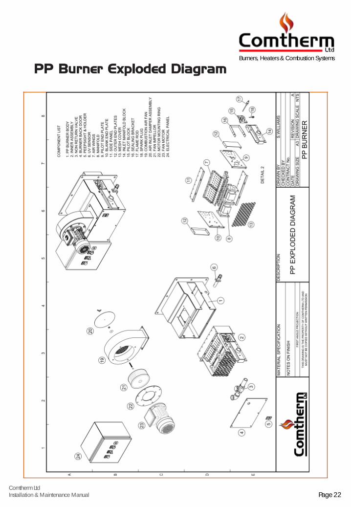
PP Burner Exploded DiagramBurners, Heaters & Combustion Systems
Page 22Comtherm LtdInstallation & Maintenance Manual

Comtherm LtdInstallation & Maintenance Manual
Comtherm Ltd, Comenco Works, Union Lane, Droitwich, Worcestershire WR9 9AZ
Burners, Heaters & Combustion Systems