install in 22-dia. or 25-dia. panel cutout - mikro...
TRANSCRIPT
Pushbutton Switch A22 G-75
Pu
shb
utt
on
Sw
itch
es
Pushbutton Switch
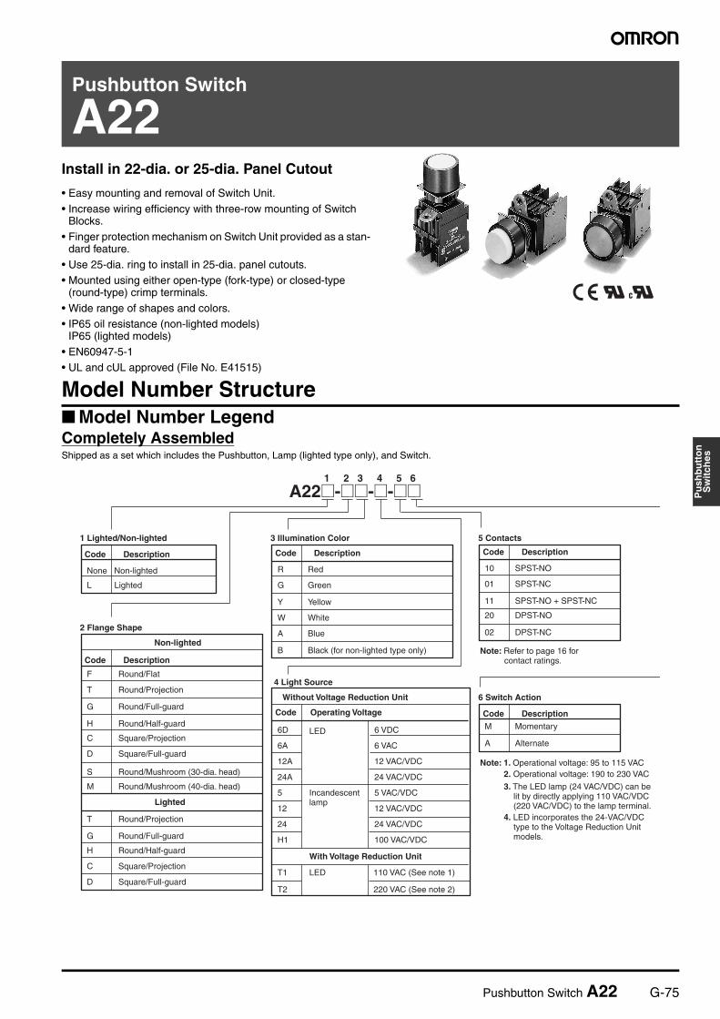
A22Install in 22-dia. or 25-dia. Panel Cutout
• Easy mounting and removal of Switch Unit.
• Increase wiring efficiency with three-row mounting of Switch Blocks.
• Finger protection mechanism on Switch Unit provided as a stan-dard feature.
• Use 25-dia. ring to install in 25-dia. panel cutouts.• Mounted using either open-type (fork-type) or closed-type
(round-type) crimp terminals.
• Wide range of shapes and colors.• IP65 oil resistance (non-lighted models)
IP65 (lighted models)
• EN60947-5-1• UL and cUL approved (File No. E41515)
Model Number Structure Model Number Legend Completely AssembledShipped as a set which includes the Pushbutton, Lamp (lighted type only), and Switch.
1 2 3 4 5 6
L
F
T
G
H
C
S
M
T
G
H
C
D
R
G
Y
W
A
B
6D 6 VDC
6A 6 VAC
12A 12 VAC/VDC
24A 24 VAC/VDC
5 5 VAC/VDC
12 12 VAC/VDC
24 24 VAC/VDC
H1 100 VAC/VDC
T1
T2
10
01
11
20
02
M
AD
Incandescent lamp
A22@-@@-@-@@
1 Lighted/Non-lighted
Code Description
None Non-lighted
Lighted
2 Flange Shape
Code Description
Round/Flat
Round/Projection
Round/Full-guard
Round/Half-guard
Square/Projection
Square/Full-guard
Round/Mushroom (30-dia. head)
Round/Mushroom (40-dia. head)
Lighted
Round/Projection
Round/Full-guard
Round/Half-guard
Square/Projection
Square/Full-guard
Non-lighted
3 Illumination Color
Code Description
Red
Green
Yellow
White
Blue
Black (for non-lighted type only)
4 Light Source
Code Operating Voltage
LED
With Voltage Reduction Unit
LED 110 VAC (See note 1)
220 VAC (See note 2)
Without Voltage Reduction Unit
5 Contacts
Code Description
SPST-NO
SPST-NC
SPST-NO + SPST-NC
DPST-NO
DPST-NC
6 Switch Action
Code DescriptionMomentary
Alternate
Note: Refer to page 16 for contact ratings.
Note: 1. Operational voltage: 95 to 115 VAC2. Operational voltage: 190 to 230 VAC
3. The LED lamp (24 VAC/VDC) can be lit by directly applying 110 VAC/VDC (220 VAC/VDC) to the lamp terminal.
4. LED incorporates the 24-VAC/VDC type to the Voltage Reduction Unit models.
G-76 Pushbutton Switch A22
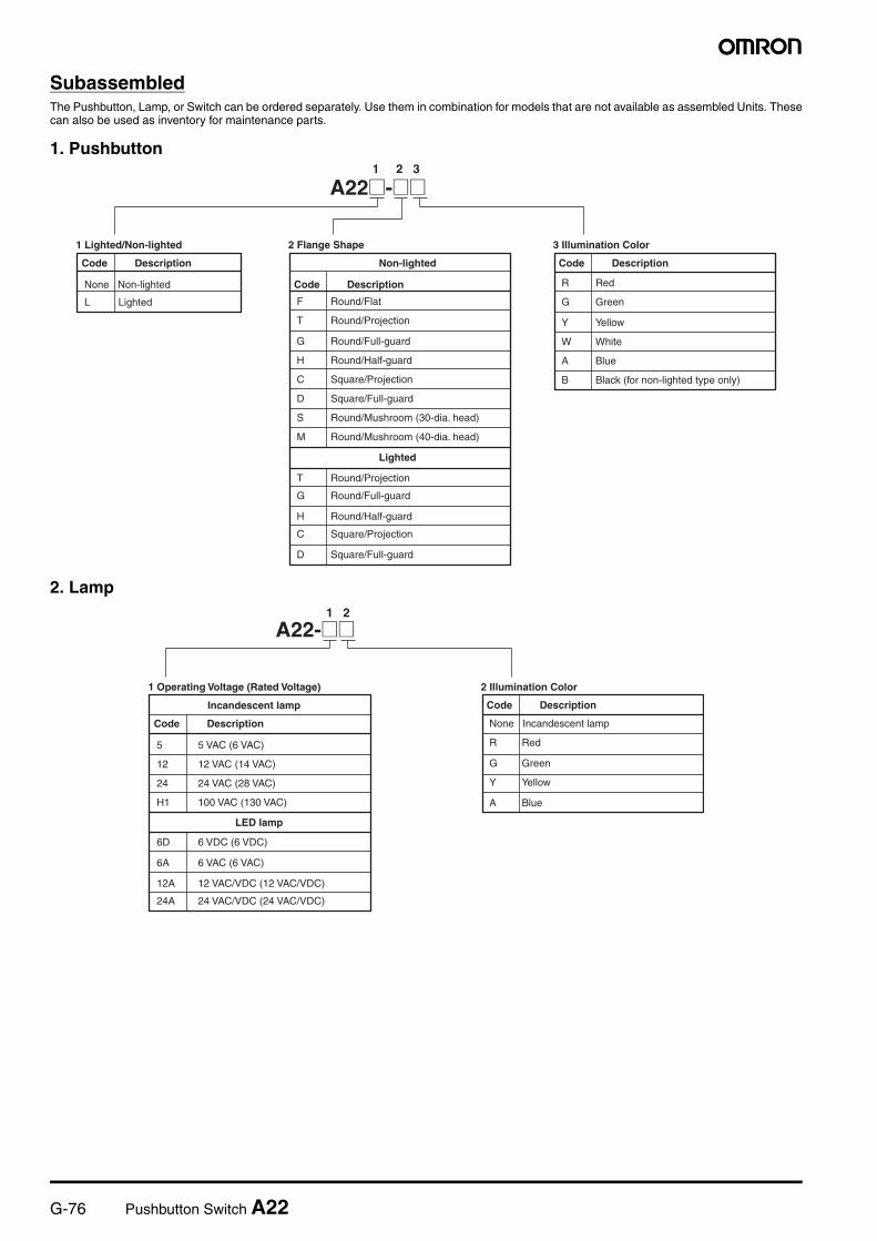
SubassembledThe Pushbutton, Lamp, or Switch can be ordered separately. Use them in combination for models that are not available as assembled Units. Thesecan also be used as inventory for maintenance parts.
1. Pushbutton
2. Lamp
1 2 3
L F
T
G
H
C
D
S
M
T
G
H
C
D
R
G
Y
W
A
B
A22@-@@
1 Lighted/Non-lighted
Code Description
None Non-lighted
Lighted
2 Flange Shape
Code Description
Round/Flat
Round/Projection
Round/Full-guard
Round/Half-guard
Square/Projection
Square/Full-guard
Round/Mushroom (30-dia. head)
Round/Mushroom (40-dia. head)
Lighted
Round/Projection
Round/Full-guard
Round/Half-guard
Square/Projection
Square/Full-guard
Non-lighted
3 Illumination Color
Code Description
Red
Green
Yellow
White
Blue
Black (for non-lighted type only)
1 2
R
G
Y
A
5 5 VAC (6 VAC)
12 12 VAC (14 VAC)
24 24 VAC (28 VAC)
H1 100 VAC (130 VAC)
6D 6 VDC (6 VDC)
6A 6 VAC (6 VAC)
12A 12 VAC/VDC (12 VAC/VDC)
24A 24 VAC/VDC (24 VAC/VDC)
A22-@@
2 Illumination Color
Code Description
None Incandescent lamp
Red
Green
Yellow
Blue
1 Operating Voltage (Rated Voltage)
Code Description
LED lamp
Incandescent lamp
Pushbutton Switch A22 G-77
Pu
shb
utt
on
Sw
itch
es
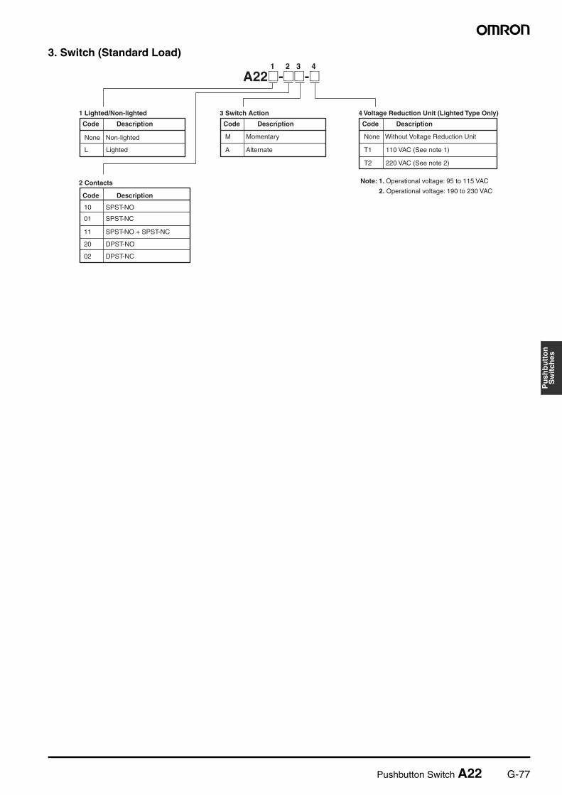
3. Switch (Standard Load)1 2 3 4
L
10
01
11
20
02
M
A T1
T2
A22@-@@-@
1 Lighted/Non-lighted
Code Description
None Non-lighted
Lighted
2 Contacts
Code Description
SPST-NO
SPST-NC
SPST-NO + SPST-NC
DPST-NO
DPST-NC
3 Switch Action
Code Description
Momentary
Alternate
4 Voltage Reduction Unit (Lighted Type Only)
Code Description
None Without Voltage Reduction Unit
110 VAC (See note 1)
220 VAC (See note 2)
Note: 1. Operational voltage: 95 to 115 VAC
2. Operational voltage: 190 to 230 VAC
G-78 Pushbutton Switch A22
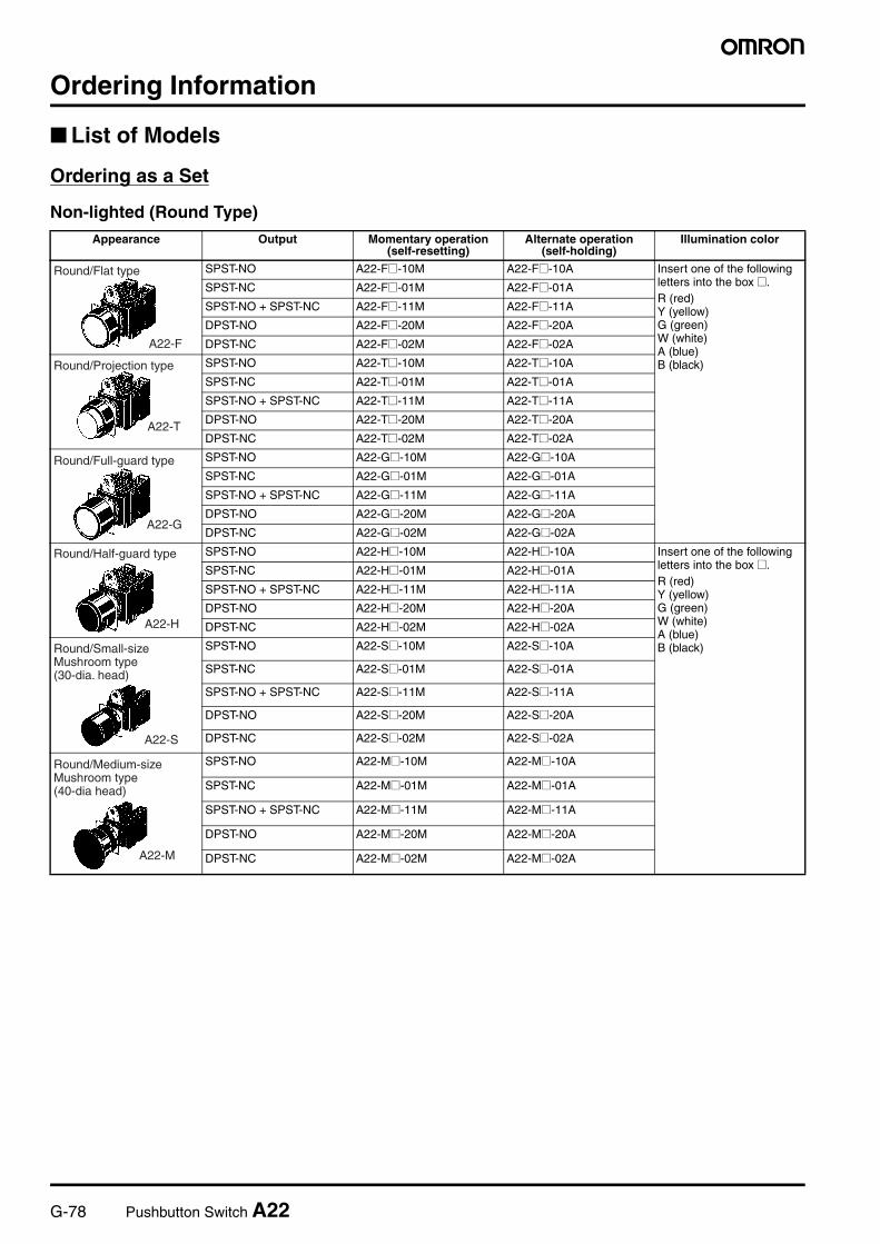
Ordering Information
List of Models
Ordering as a Set
Non-lighted (Round Type)
Appearance Output Momentary operation (self-resetting)
Alternate operation (self-holding)
Illumination color
SPST-NO A22-F@-10M A22-F@-10A Insert one of the following letters into the box @.R (red)Y (yellow)G (green)W (white)A (blue)B (black)
SPST-NC A22-F@-01M A22-F@-01A
SPST-NO + SPST-NC A22-F@-11M A22-F@-11A
DPST-NO A22-F@-20M A22-F@-20A
DPST-NC A22-F@-02M A22-F@-02A
SPST-NO A22-T@-10M A22-T@-10A
SPST-NC A22-T@-01M A22-T@-01A
SPST-NO + SPST-NC A22-T@-11M A22-T@-11A
DPST-NO A22-T@-20M A22-T@-20A
DPST-NC A22-T@-02M A22-T@-02A
SPST-NO A22-G@-10M A22-G@-10A
SPST-NC A22-G@-01M A22-G@-01A
SPST-NO + SPST-NC A22-G@-11M A22-G@-11A
DPST-NO A22-G@-20M A22-G@-20A
DPST-NC A22-G@-02M A22-G@-02A
SPST-NO A22-H@-10M A22-H@-10A Insert one of the following letters into the box @.R (red)Y (yellow)G (green)W (white)A (blue)B (black)
SPST-NC A22-H@-01M A22-H@-01A
SPST-NO + SPST-NC A22-H@-11M A22-H@-11A
DPST-NO A22-H@-20M A22-H@-20A
DPST-NC A22-H@-02M A22-H@-02A
SPST-NO A22-S@-10M A22-S@-10A
SPST-NC A22-S@-01M A22-S@-01A
SPST-NO + SPST-NC A22-S@-11M A22-S@-11A
DPST-NO A22-S@-20M A22-S@-20A
DPST-NC A22-S@-02M A22-S@-02A
SPST-NO A22-M@-10M A22-M@-10A
SPST-NC A22-M@-01M A22-M@-01A
SPST-NO + SPST-NC A22-M@-11M A22-M@-11A
DPST-NO A22-M@-20M A22-M@-20A
DPST-NC A22-M@-02M A22-M@-02A
Round/Flat type
A22-F
Round/Projection type
A22-T
Round/Full-guard type
A22-G
Round/Half-guard type
A22-H
A22-S
Round/Small-size Mushroom type (30-dia. head)
A22-M
Round/Medium-size Mushroom type (40-dia head)
Pushbutton Switch A22 G-79
Pu
shb
utt
on
Sw
itch
es
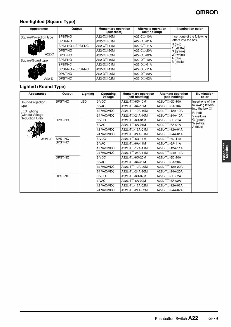
Non-lighted (Square Type)
Lighted (Round Type)
Appearance Output Momentary operation (self-reset)
Alternate operation (self-holding)
Illumination color
SPST-NO A22-C@-10M A22-C@-10A Insert one of the following letters into the box @.R (red)Y (yellow)G (green)W (white)A (blue)B (black)
SPST-NC A22-C@-01M A22-C@-01A
SPST-NO + SPST-NC A22-C@-11M A22-C@-11A
DPST-NO A22-C@-20M A22-C@-20A
DPST-NC A22-C@-02M A22-C@-02A
SPST-NO A22-D@-10M A22-D@-10A
SPST-NC A22-D@-01M A22-D@-01A
SPST-NO + SPST-NC A22-D@-11M A22-D@-11A
DPST-NO A22-D@-20M A22-D@-20A
DPST-NC A22-D@-02M A22-D@-02A
Square/Projection type
A22-C
Square/Guard type
A22-D
Appearance Output Lighting Operating voltage
Momentary operation (self-resetting)
Alternate operation (self-holding)
Illumination color
SPST-NO LED 6 VDC A22L-T@-6D-10M A22L-T@-6D-10A Insert one of the following letters into the box @.R (red)Y (yellow)G (green)W (white)A (blue)
6 VAC A22L-T@-6A-10M A22L-T@-6A-10A
12 VAC/VDC A22L-T@-12A-10M A22L-T@-12A-10A
24 VAC/VDC A22L-T@-24A-10M A22L-T@-24A-10A
SPST-NC 6 VDC A22L-T@-6D-01M A22L-T@-6D-01A
6 VAC A22L-T@-6A-01M A22L-T@-6A-01A
12 VAC/VDC A22L-T@-12A-01M A22L-T@-12A-01A
24 VAC/VDC A22L-T@-24A-01M A22L-T@-24A-01A
SPST-NO + SPST-NC
6 VDC A22L-T@-6D-11M A22L-T@-6D-11A
6 VAC A22L-T@-6A-11M A22L-T@-6A-11A
12 VAC/VDC A22L-T@-12A-11M A22L-T@-12A-11A
24 VAC/VDC A22L-T@-24A-11M A22L-T@-24A-11A
DPST-NO 6 VDC A22L-T@-6D-20M A22L-T@-6D-20A
6 VAC A22L-T@-6A-20M A22L-T@-6A-20A
12 VAC/VDC A22L-T@-12A-20M A22L-T@-12A-20A
24 VAC/VDC A22L-T@-24A-20M A22L-T@-24A-20A
DPST-NC 6 VDC A22L-T@-6D-02M A22L-T@-6D-02A
6 VAC A22L-T@-6A-02M A22L-T@-6A-02A
12 VAC/VDC A22L-T@-12A-02M A22L-T@-12A-02A
24 VAC/VDC A22L-T@-24A-02M A22L-T@-24A-02A
A22L-T
Round/Projection type
LED lighting (without Voltage Reduction Unit)
G-80 Pushbutton Switch A22
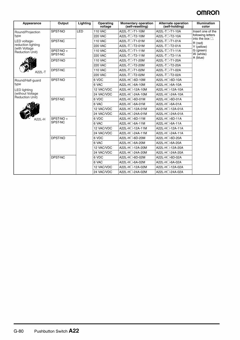
SPST-NO LED 110 VAC A22L-T@-T1-10M A22L-T@-T1-10A Insert one of the following letters into the box @.R (red)Y (yellow)G (green)W (white)A (blue)
220 VAC A22L-T@-T2-10M A22L-T@-T2-10A
SPST-NC 110 VAC A22L-T@-T1-01M A22L-T@-T1-01A
220 VAC A22L-T@-T2-01M A22L-T@-T2-01A
SPST-NO + SPST-NC
110 VAC A22L-T@-T1-11M A22L-T@-T1-11A
220 VAC A22L-T@-T2-11M A22L-T@-T2-11A
DPST-NO 110 VAC A22L-T@-T1-20M A22L-T@-T1-20A
220 VAC A22L-T@-T2-20M A22L-T@-T2-20A
DPST-NC 110 VAC A22L-T@-T1-02M A22L-T@-T1-02A
220 VAC A22L-T@-T2-02M A22L-T@-T2-02A
SPST-NO 6 VDC A22L-H@-6D-10M A22L-H@-6D-10A
6 VAC A22L-H@-6A-10M A22L-H@-6A-10A
12 VAC/VDC A22L-H@-12A-10M A22L-H@-12A-10A
24 VAC/VDC A22L-H@-24A-10M A22L-H@-24A-10A
SPST-NC 6 VDC A22L-H@-6D-01M A22L-H@-6D-01A
6 VAC A22L-H@-6A-01M A22L-H@-6A-01A
12 VAC/VDC A22L-H@-12A-01M A22L-H@-12A-01A
24 VAC/VDC A22L-H@-24A-01M A22L-H@-24A-01A
SPST-NO + SPST-NC
6 VDC A22L-H@-6D-11M A22L-H@-6D-11A
6 VAC A22L-H@-6A-11M A22L-H@-6A-11A
12 VAC/VDC A22L-H@-12A-11M A22L-H@-12A-11A
24 VAC/VDC A22L-H@-24A-11M A22L-H@-24A-11A
DPST-NO 6 VDC A22L-H@-6D-20M A22L-H@-6D-20A
6 VAC A22L-H@-6A-20M A22L-H@-6A-20A
12 VAC/VDC A22L-H@-12A-20M A22L-H@-12A-20A
24 VAC/VDC A22L-H@-24A-20M A22L-H@-24A-20A
DPST-NC 6 VDC A22L-H@-6D-02M A22L-H@-6D-02A
6 VAC A22L-H@-6A-02M A22L-H@-6A-02A
12 VAC/VDC A22L-H@-12A-02M A22L-H@-12A-02A
24 VAC/VDC A22L-H@-24A-02M A22L-H@-24A-02A
Appearance Output Lighting Operating voltage
Momentary operation (self-resetting)
Alternate operation (self-holding)
Illumination color
A22L-T
Round/Projection type
LED voltage-reduction lighting (with Voltage Reduction Unit)
A22L-H
Round/Half-guard type
LED lighting (without Voltage Reduction Unit)
Pushbutton Switch A22 G-81
Pu
shb
utt
on
Sw
itch
es
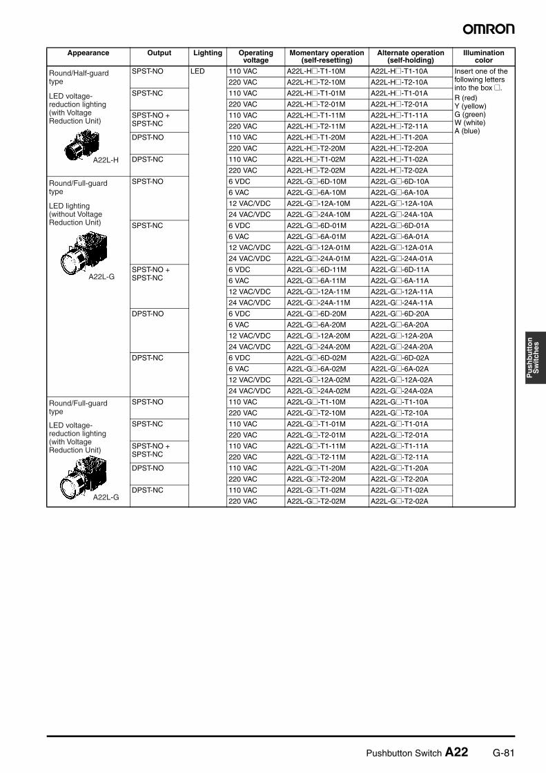
SPST-NO LED 110 VAC A22L-H@-T1-10M A22L-H@-T1-10A Insert one of the following letters into the box @.R (red)Y (yellow)G (green)W (white)A (blue)
220 VAC A22L-H@-T2-10M A22L-H@-T2-10A
SPST-NC 110 VAC A22L-H@-T1-01M A22L-H@-T1-01A
220 VAC A22L-H@-T2-01M A22L-H@-T2-01A
SPST-NO + SPST-NC
110 VAC A22L-H@-T1-11M A22L-H@-T1-11A
220 VAC A22L-H@-T2-11M A22L-H@-T2-11A
DPST-NO 110 VAC A22L-H@-T1-20M A22L-H@-T1-20A
220 VAC A22L-H@-T2-20M A22L-H@-T2-20A
DPST-NC 110 VAC A22L-H@-T1-02M A22L-H@-T1-02A
220 VAC A22L-H@-T2-02M A22L-H@-T2-02A
SPST-NO 6 VDC A22L-G@-6D-10M A22L-G@-6D-10A
6 VAC A22L-G@-6A-10M A22L-G@-6A-10A
12 VAC/VDC A22L-G@-12A-10M A22L-G@-12A-10A
24 VAC/VDC A22L-G@-24A-10M A22L-G@-24A-10A
SPST-NC 6 VDC A22L-G@-6D-01M A22L-G@-6D-01A
6 VAC A22L-G@-6A-01M A22L-G@-6A-01A
12 VAC/VDC A22L-G@-12A-01M A22L-G@-12A-01A
24 VAC/VDC A22L-G@-24A-01M A22L-G@-24A-01A
SPST-NO + SPST-NC
6 VDC A22L-G@-6D-11M A22L-G@-6D-11A
6 VAC A22L-G@-6A-11M A22L-G@-6A-11A
12 VAC/VDC A22L-G@-12A-11M A22L-G@-12A-11A
24 VAC/VDC A22L-G@-24A-11M A22L-G@-24A-11A
DPST-NO 6 VDC A22L-G@-6D-20M A22L-G@-6D-20A
6 VAC A22L-G@-6A-20M A22L-G@-6A-20A
12 VAC/VDC A22L-G@-12A-20M A22L-G@-12A-20A
24 VAC/VDC A22L-G@-24A-20M A22L-G@-24A-20A
DPST-NC 6 VDC A22L-G@-6D-02M A22L-G@-6D-02A
6 VAC A22L-G@-6A-02M A22L-G@-6A-02A
12 VAC/VDC A22L-G@-12A-02M A22L-G@-12A-02A
24 VAC/VDC A22L-G@-24A-02M A22L-G@-24A-02A
SPST-NO 110 VAC A22L-G@-T1-10M A22L-G@-T1-10A
220 VAC A22L-G@-T2-10M A22L-G@-T2-10A
SPST-NC 110 VAC A22L-G@-T1-01M A22L-G@-T1-01A
220 VAC A22L-G@-T2-01M A22L-G@-T2-01A
SPST-NO + SPST-NC
110 VAC A22L-G@-T1-11M A22L-G@-T1-11A
220 VAC A22L-G@-T2-11M A22L-G@-T2-11A
DPST-NO 110 VAC A22L-G@-T1-20M A22L-G@-T1-20A
220 VAC A22L-G@-T2-20M A22L-G@-T2-20A
DPST-NC 110 VAC A22L-G@-T1-02M A22L-G@-T1-02A
220 VAC A22L-G@-T2-02M A22L-G@-T2-02A
Appearance Output Lighting Operating voltage
Momentary operation (self-resetting)
Alternate operation (self-holding)
Illumination color
A22L-H
Round/Half-guard type
LED voltage-reduction lighting (with Voltage Reduction Unit)
A22L-G
Round/Full-guard type
LED lighting (without Voltage Reduction Unit)
A22L-G
Round/Full-guard type
LED voltage-reduction lighting (with Voltage Reduction Unit)
G-82 Pushbutton Switch A22
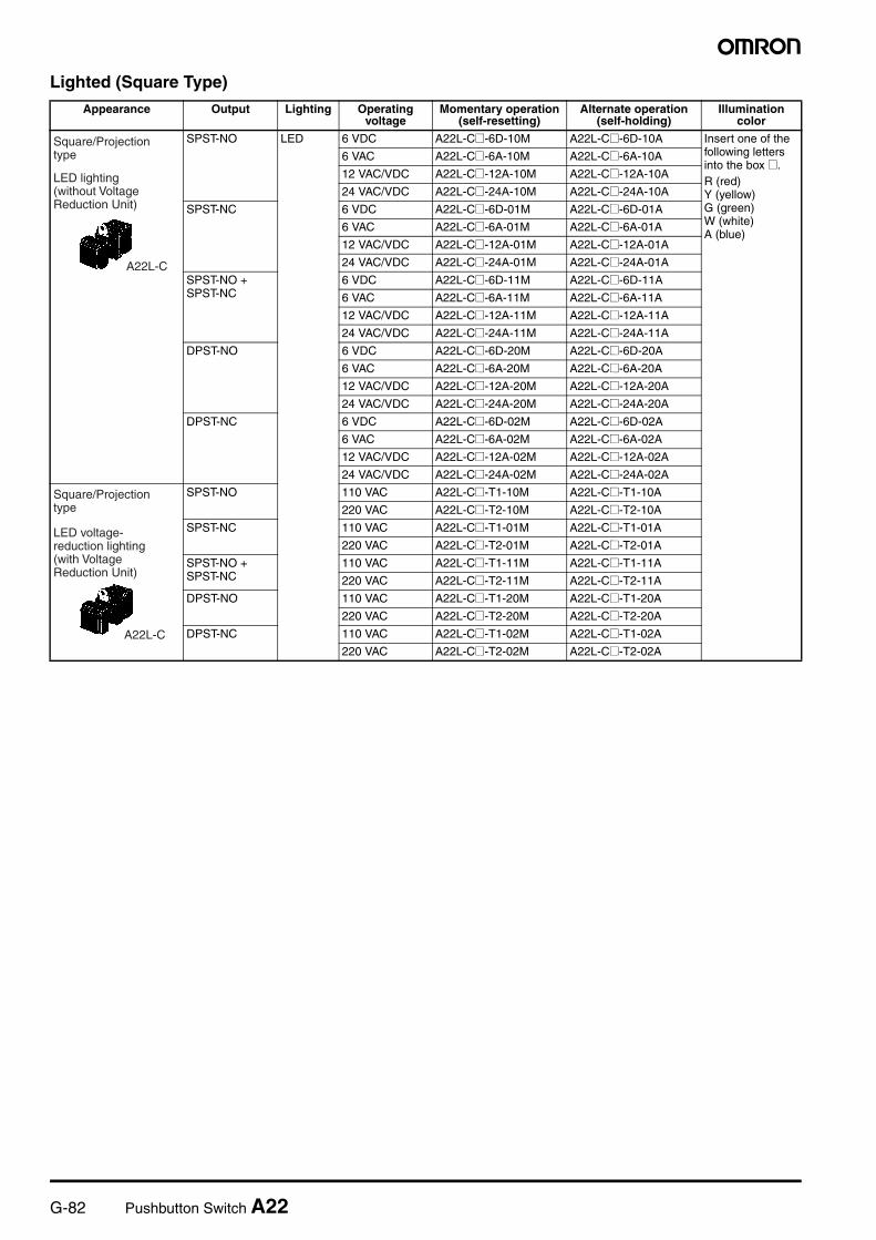
Lighted (Square Type)
Appearance Output Lighting Operating voltage
Momentary operation (self-resetting)
Alternate operation (self-holding)
Illumination color
SPST-NO LED 6 VDC A22L-C@-6D-10M A22L-C@-6D-10A Insert one of the following letters into the box @.R (red)Y (yellow)G (green)W (white)A (blue)
6 VAC A22L-C@-6A-10M A22L-C@-6A-10A
12 VAC/VDC A22L-C@-12A-10M A22L-C@-12A-10A
24 VAC/VDC A22L-C@-24A-10M A22L-C@-24A-10A
SPST-NC 6 VDC A22L-C@-6D-01M A22L-C@-6D-01A
6 VAC A22L-C@-6A-01M A22L-C@-6A-01A
12 VAC/VDC A22L-C@-12A-01M A22L-C@-12A-01A
24 VAC/VDC A22L-C@-24A-01M A22L-C@-24A-01A
SPST-NO + SPST-NC
6 VDC A22L-C@-6D-11M A22L-C@-6D-11A
6 VAC A22L-C@-6A-11M A22L-C@-6A-11A
12 VAC/VDC A22L-C@-12A-11M A22L-C@-12A-11A
24 VAC/VDC A22L-C@-24A-11M A22L-C@-24A-11A
DPST-NO 6 VDC A22L-C@-6D-20M A22L-C@-6D-20A
6 VAC A22L-C@-6A-20M A22L-C@-6A-20A
12 VAC/VDC A22L-C@-12A-20M A22L-C@-12A-20A
24 VAC/VDC A22L-C@-24A-20M A22L-C@-24A-20A
DPST-NC 6 VDC A22L-C@-6D-02M A22L-C@-6D-02A
6 VAC A22L-C@-6A-02M A22L-C@-6A-02A
12 VAC/VDC A22L-C@-12A-02M A22L-C@-12A-02A
24 VAC/VDC A22L-C@-24A-02M A22L-C@-24A-02A
SPST-NO 110 VAC A22L-C@-T1-10M A22L-C@-T1-10A
220 VAC A22L-C@-T2-10M A22L-C@-T2-10A
SPST-NC 110 VAC A22L-C@-T1-01M A22L-C@-T1-01A
220 VAC A22L-C@-T2-01M A22L-C@-T2-01A
SPST-NO + SPST-NC
110 VAC A22L-C@-T1-11M A22L-C@-T1-11A
220 VAC A22L-C@-T2-11M A22L-C@-T2-11A
DPST-NO 110 VAC A22L-C@-T1-20M A22L-C@-T1-20A
220 VAC A22L-C@-T2-20M A22L-C@-T2-20A
DPST-NC 110 VAC A22L-C@-T1-02M A22L-C@-T1-02A
220 VAC A22L-C@-T2-02M A22L-C@-T2-02A
A22L-C
Square/Projection type
LED lighting (without Voltage Reduction Unit)
A22L-C
Square/Projection type
LED voltage-reduction lighting (with Voltage Reduction Unit)
Pushbutton Switch A22 G-83
Pu
shb
utt
on
Sw
itch
es
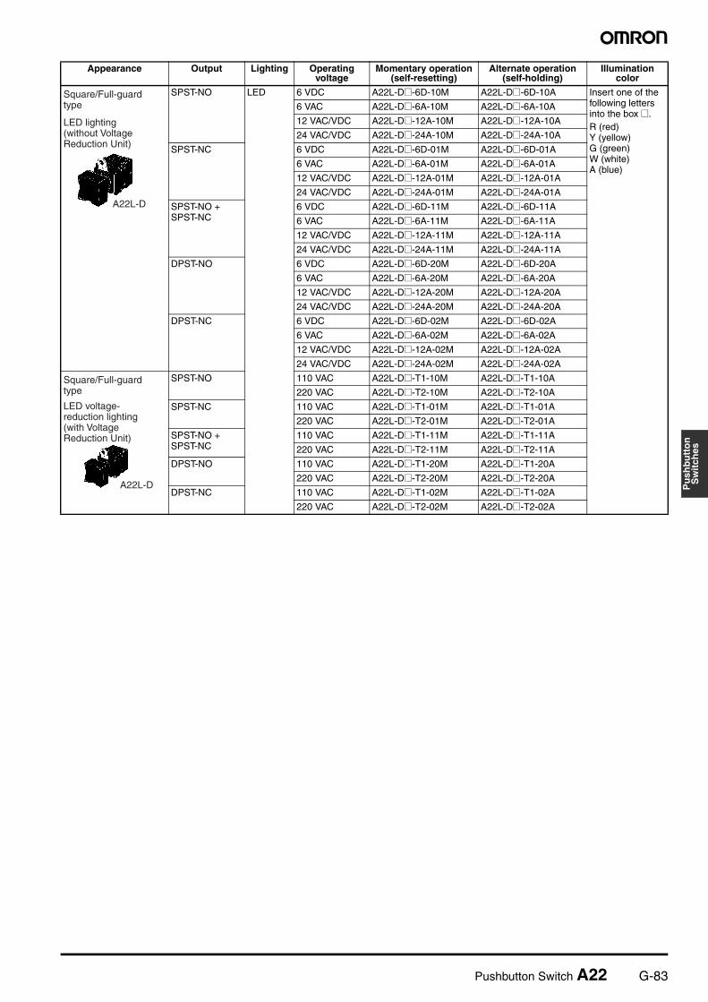
SPST-NO LED 6 VDC A22L-D@-6D-10M A22L-D@-6D-10A Insert one of the following letters into the box @.R (red)Y (yellow)G (green)W (white)A (blue)
6 VAC A22L-D@-6A-10M A22L-D@-6A-10A
12 VAC/VDC A22L-D@-12A-10M A22L-D@-12A-10A
24 VAC/VDC A22L-D@-24A-10M A22L-D@-24A-10A
SPST-NC 6 VDC A22L-D@-6D-01M A22L-D@-6D-01A
6 VAC A22L-D@-6A-01M A22L-D@-6A-01A
12 VAC/VDC A22L-D@-12A-01M A22L-D@-12A-01A
24 VAC/VDC A22L-D@-24A-01M A22L-D@-24A-01A
SPST-NO + SPST-NC
6 VDC A22L-D@-6D-11M A22L-D@-6D-11A
6 VAC A22L-D@-6A-11M A22L-D@-6A-11A
12 VAC/VDC A22L-D@-12A-11M A22L-D@-12A-11A
24 VAC/VDC A22L-D@-24A-11M A22L-D@-24A-11A
DPST-NO 6 VDC A22L-D@-6D-20M A22L-D@-6D-20A
6 VAC A22L-D@-6A-20M A22L-D@-6A-20A
12 VAC/VDC A22L-D@-12A-20M A22L-D@-12A-20A
24 VAC/VDC A22L-D@-24A-20M A22L-D@-24A-20A
DPST-NC 6 VDC A22L-D@-6D-02M A22L-D@-6D-02A
6 VAC A22L-D@-6A-02M A22L-D@-6A-02A
12 VAC/VDC A22L-D@-12A-02M A22L-D@-12A-02A
24 VAC/VDC A22L-D@-24A-02M A22L-D@-24A-02A
SPST-NO 110 VAC A22L-D@-T1-10M A22L-D@-T1-10A
220 VAC A22L-D@-T2-10M A22L-D@-T2-10A
SPST-NC 110 VAC A22L-D@-T1-01M A22L-D@-T1-01A
220 VAC A22L-D@-T2-01M A22L-D@-T2-01A
SPST-NO + SPST-NC
110 VAC A22L-D@-T1-11M A22L-D@-T1-11A
220 VAC A22L-D@-T2-11M A22L-D@-T2-11A
DPST-NO 110 VAC A22L-D@-T1-20M A22L-D@-T1-20A
220 VAC A22L-D@-T2-20M A22L-D@-T2-20A
DPST-NC 110 VAC A22L-D@-T1-02M A22L-D@-T1-02A
220 VAC A22L-D@-T2-02M A22L-D@-T2-02A
Appearance Output Lighting Operating voltage
Momentary operation (self-resetting)
Alternate operation (self-holding)
Illumination color
A22L-D
Square/Full-guard type
LED lighting (without Voltage Reduction Unit)
A22L-D
Square/Full-guard type
LED voltage-reduction lighting (with Voltage Reduction Unit)
G-84 Pushbutton Switch A22
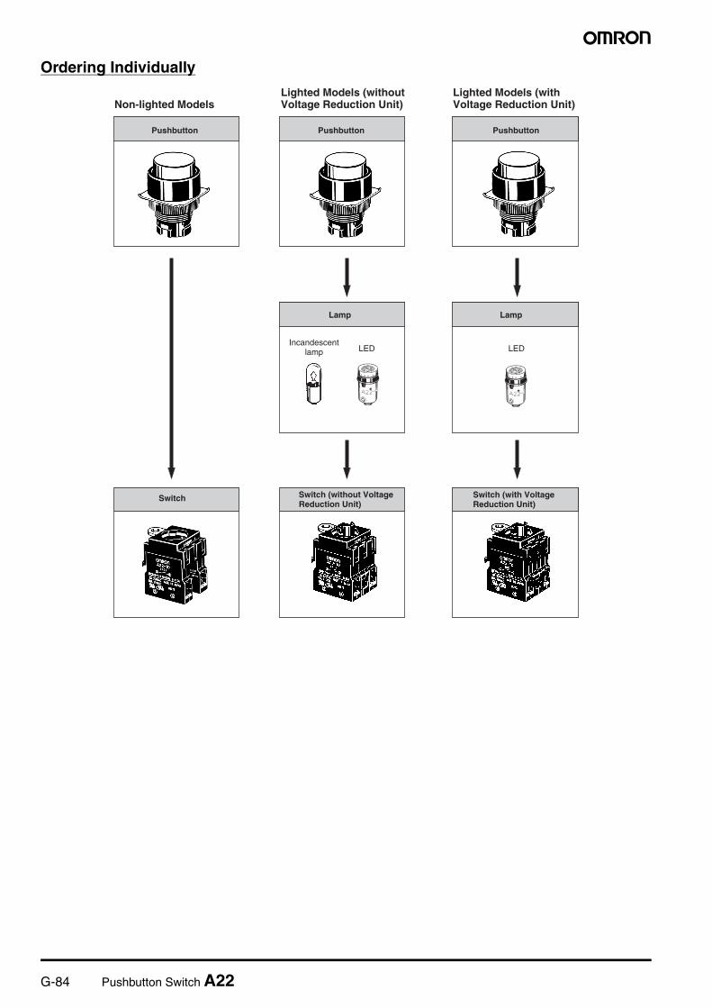
Ordering Individually
Non-lighted ModelsLighted Models (withoutVoltage Reduction Unit)
Pushbutton Pushbutton Pushbutton
Switch Switch (without VoltageReduction Unit)
Lamp Lamp
LED LED
Lighted Models (withVoltage Reduction Unit)
Incandescent lamp
Switch (with VoltageReduction Unit)
Pushbutton Switch A22 G-85
Pu
shb
utt
on
Sw
itch
es
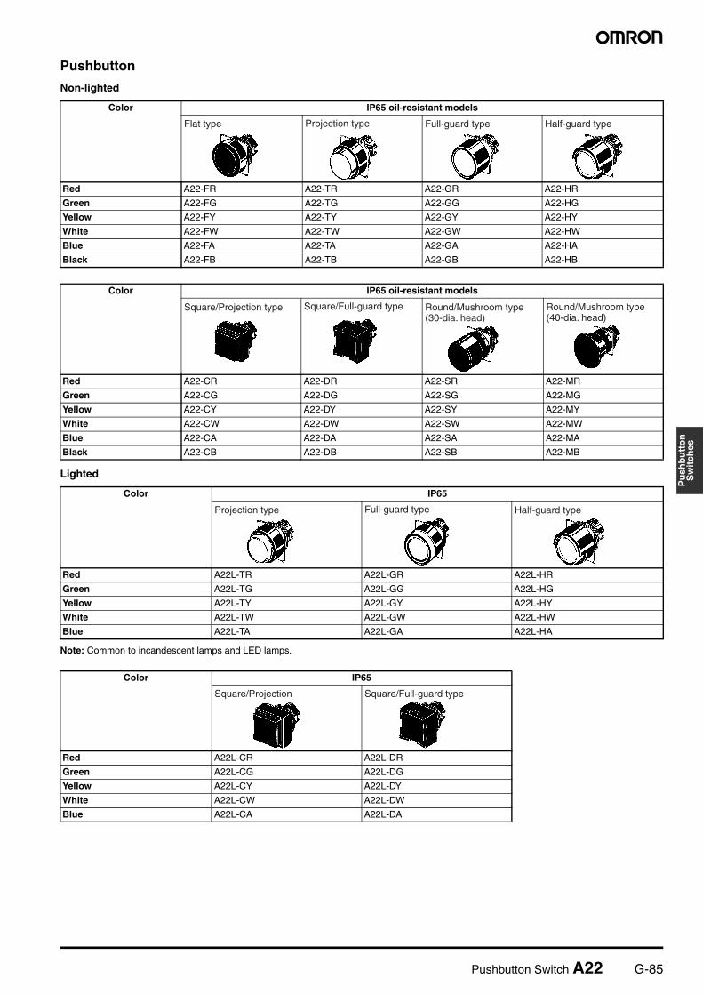
Pushbutton
Non-lighted
Lighted
Note: Common to incandescent lamps and LED lamps.
Color IP65 oil-resistant models
Red A22-FR A22-TR A22-GR A22-HR
Green A22-FG A22-TG A22-GG A22-HG
Yellow A22-FY A22-TY A22-GY A22-HY
White A22-FW A22-TW A22-GW A22-HW
Blue A22-FA A22-TA A22-GA A22-HA
Black A22-FB A22-TB A22-GB A22-HB
Color IP65 oil-resistant models
Red A22-CR A22-DR A22-SR A22-MR
Green A22-CG A22-DG A22-SG A22-MG
Yellow A22-CY A22-DY A22-SY A22-MY
White A22-CW A22-DW A22-SW A22-MW
Blue A22-CA A22-DA A22-SA A22-MA
Black A22-CB A22-DB A22-SB A22-MB
Flat type Projection type Full-guard type Half-guard type
Square/Projection type Square/Full-guard type Round/Mushroom type (30-dia. head)
Round/Mushroom type (40-dia. head)
Color IP65
Red A22L-TR A22L-GR A22L-HR
Green A22L-TG A22L-GG A22L-HG
Yellow A22L-TY A22L-GY A22L-HY
White A22L-TW A22L-GW A22L-HW
Blue A22L-TA A22L-GA A22L-HA
Color IP65
Red A22L-CR A22L-DR
Green A22L-CG A22L-DG
Yellow A22L-CY A22L-DY
White A22L-CW A22L-DW
Blue A22L-CA A22L-DA
Projection type Full-guard type Half-guard type
Square/Projection Square/Full-guard type
G-86 Pushbutton Switch A22
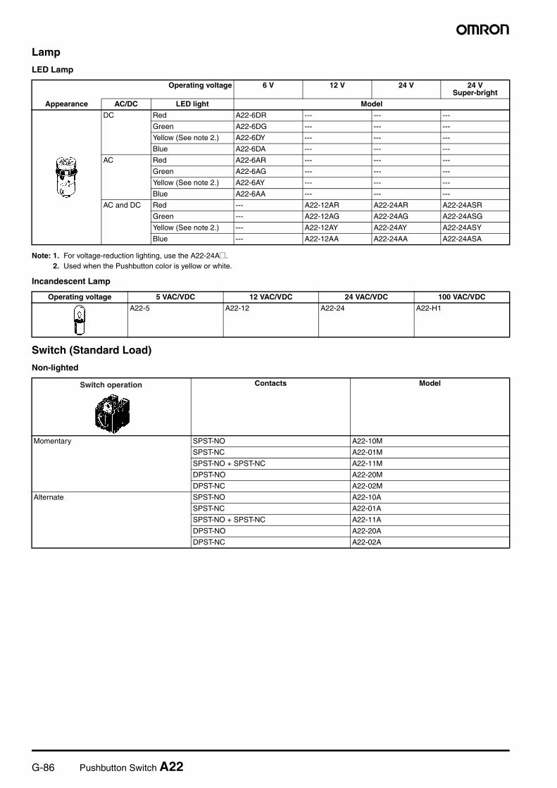
Lamp
LED Lamp
Note: 1. For voltage-reduction lighting, use the [email protected]. Used when the Pushbutton color is yellow or white.
Incandescent Lamp
Switch (Standard Load)
Non-lighted
Operating voltage 6 V 12 V 24 V 24 VSuper-bright
Appearance AC/DC LED light Model
DC Red A22-6DR --- --- ---
Green A22-6DG --- --- ---
Yellow (See note 2.) A22-6DY --- --- ---
Blue A22-6DA --- --- ---
AC Red A22-6AR --- --- ---
Green A22-6AG --- --- ---
Yellow (See note 2.) A22-6AY --- --- ---
Blue A22-6AA --- --- ---
AC and DC Red --- A22-12AR A22-24AR A22-24ASR
Green --- A22-12AG A22-24AG A22-24ASG
Yellow (See note 2.) --- A22-12AY A22-24AY A22-24ASY
Blue --- A22-12AA A22-24AA A22-24ASA
Operating voltage 5 VAC/VDC 12 VAC/VDC 24 VAC/VDC 100 VAC/VDC
A22-5 A22-12 A22-24 A22-H1
Contacts Model
Momentary SPST-NO A22-10M
SPST-NC A22-01M
SPST-NO + SPST-NC A22-11M
DPST-NO A22-20M
DPST-NC A22-02M
Alternate SPST-NO A22-10A
SPST-NC A22-01A
SPST-NO + SPST-NC A22-11A
DPST-NO A22-20A
DPST-NC A22-02A
Switch operation
Pushbutton Switch A22 G-87
Pu
shb
utt
on
Sw
itch
es
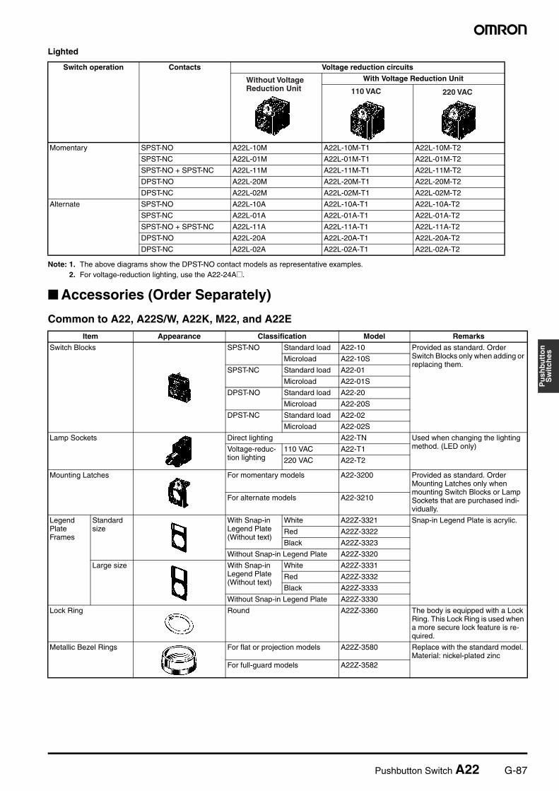
Lighted
Note: 1. The above diagrams show the DPST-NO contact models as representative examples.2. For voltage-reduction lighting, use the A22-24A@.
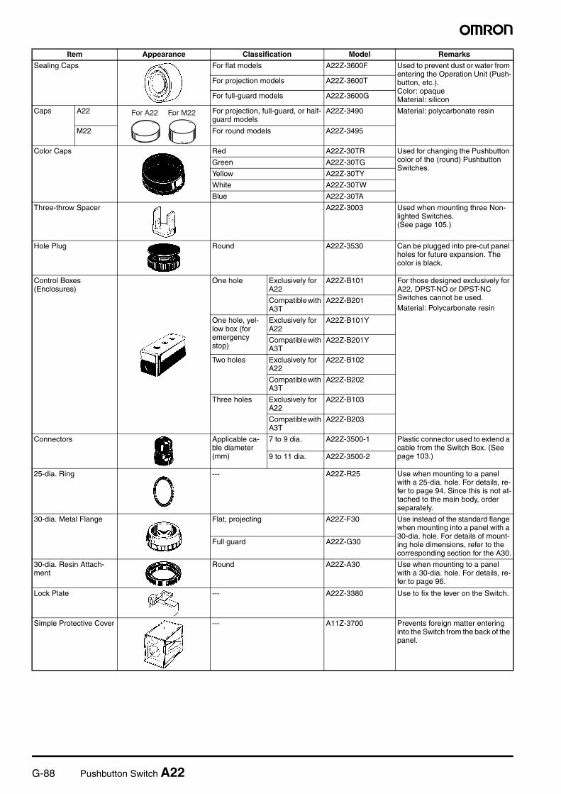
Accessories (Order Separately)
Common to A22, A22S/W, A22K, M22, and A22E
Switch operation Contacts Voltage reduction circuits
With Voltage Reduction Unit
Momentary SPST-NO A22L-10M A22L-10M-T1 A22L-10M-T2
SPST-NC A22L-01M A22L-01M-T1 A22L-01M-T2
SPST-NO + SPST-NC A22L-11M A22L-11M-T1 A22L-11M-T2
DPST-NO A22L-20M A22L-20M-T1 A22L-20M-T2
DPST-NC A22L-02M A22L-02M-T1 A22L-02M-T2
Alternate SPST-NO A22L-10A A22L-10A-T1 A22L-10A-T2
SPST-NC A22L-01A A22L-01A-T1 A22L-01A-T2
SPST-NO + SPST-NC A22L-11A A22L-11A-T1 A22L-11A-T2
DPST-NO A22L-20A A22L-20A-T1 A22L-20A-T2
DPST-NC A22L-02A A22L-02A-T1 A22L-02A-T2
Without Voltage Reduction Unit 110 VAC 220 VAC
Item Appearance Classification Model Remarks
Switch Blocks SPST-NO Standard load A22-10 Provided as standard. Order Switch Blocks only when adding or replacing them.
Microload A22-10S
SPST-NC Standard load A22-01
Microload A22-01S
DPST-NO Standard load A22-20
Microload A22-20S
DPST-NC Standard load A22-02
Microload A22-02S
Lamp Sockets Direct lighting A22-TN Used when changing the lighting method. (LED only)Voltage-reduc-
tion lighting110 VAC A22-T1
220 VAC A22-T2
Mounting Latches For momentary models A22-3200 Provided as standard. Order Mounting Latches only when mounting Switch Blocks or Lamp Sockets that are purchased indi-vidually.
For alternate models A22-3210
Legend Plate Frames
Standard size
With Snap-in Legend Plate (Without text)
White A22Z-3321 Snap-in Legend Plate is acrylic.
Red A22Z-3322
Black A22Z-3323
Without Snap-in Legend Plate A22Z-3320
Large size With Snap-in Legend Plate (Without text)
White A22Z-3331
Red A22Z-3332
Black A22Z-3333
Without Snap-in Legend Plate A22Z-3330
Lock Ring Round A22Z-3360 The body is equipped with a Lock Ring. This Lock Ring is used when a more secure lock feature is re-quired.
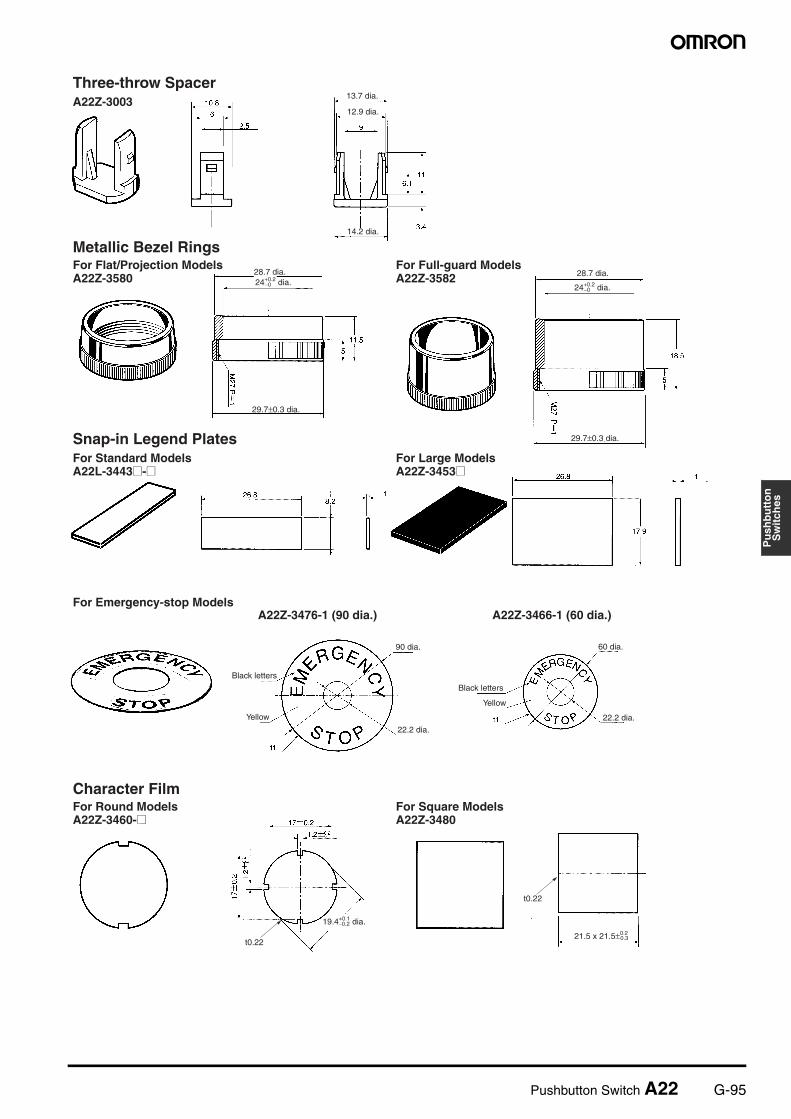
Metallic Bezel Rings For flat or projection models A22Z-3580 Replace with the standard model.Material: nickel-plated zinc
For full-guard models A22Z-3582
G-88 Pushbutton Switch A22
Sealing Caps For flat models A22Z-3600F Used to prevent dust or water from entering the Operation Unit (Push-button, etc.).Color: opaqueMaterial: silicon
For projection models A22Z-3600T
For full-guard models A22Z-3600G
Caps A22 For projection, full-guard, or half-guard models
A22Z-3490 Material: polycarbonate resin
M22 For round models A22Z-3495
Color Caps Red A22Z-30TR Used for changing the Pushbutton color of the (round) Pushbutton Switches.
Green A22Z-30TG
Yellow A22Z-30TY
White A22Z-30TW
Blue A22Z-30TA
Three-throw Spacer A22Z-3003 Used when mounting three Non-lighted Switches.(See page 105.)
Hole Plug Round A22Z-3530 Can be plugged into pre-cut panel holes for future expansion. The color is black.
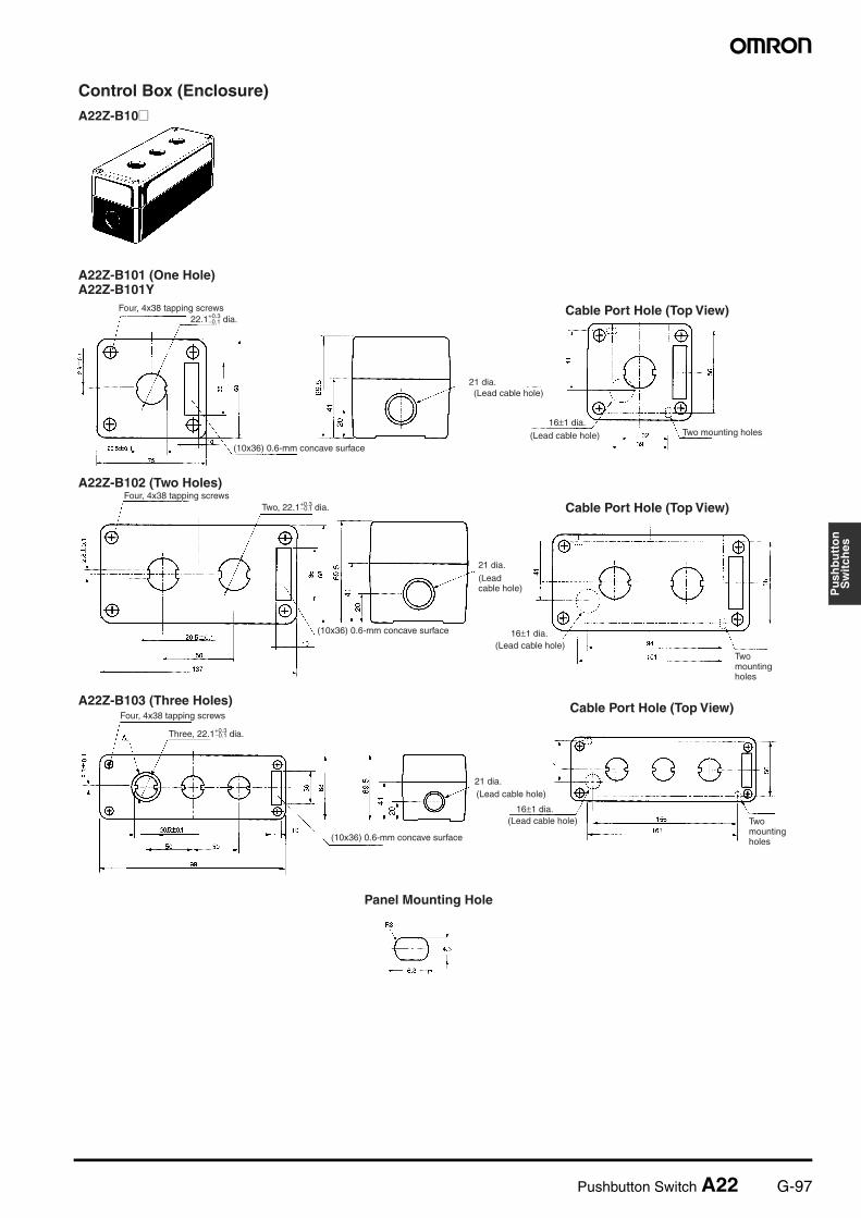
Control Boxes(Enclosures)
One hole Exclusively for A22
A22Z-B101 For those designed exclusively for A22, DPST-NO or DPST-NC Switches cannot be used.Material: Polycarbonate resin
Compatible with A3T
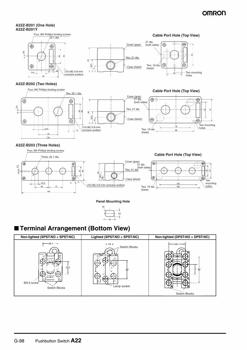
A22Z-B201
One hole, yel-low box (for emergency stop)
Exclusively for A22
A22Z-B101Y
Compatible with A3T
A22Z-B201Y
Two holes Exclusively for A22
A22Z-B102
Compatible with A3T
A22Z-B202
Three holes Exclusively for A22
A22Z-B103
Compatible with A3T
A22Z-B203
Connectors Applicable ca-ble diameter (mm)
7 to 9 dia. A22Z-3500-1 Plastic connector used to extend a cable from the Switch Box. (See page 103.)9 to 11 dia. A22Z-3500-2
25-dia. Ring --- A22Z-R25 Use when mounting to a panel with a 25-dia. hole. For details, re-fer to page 94. Since this is not at-tached to the main body, order separately.
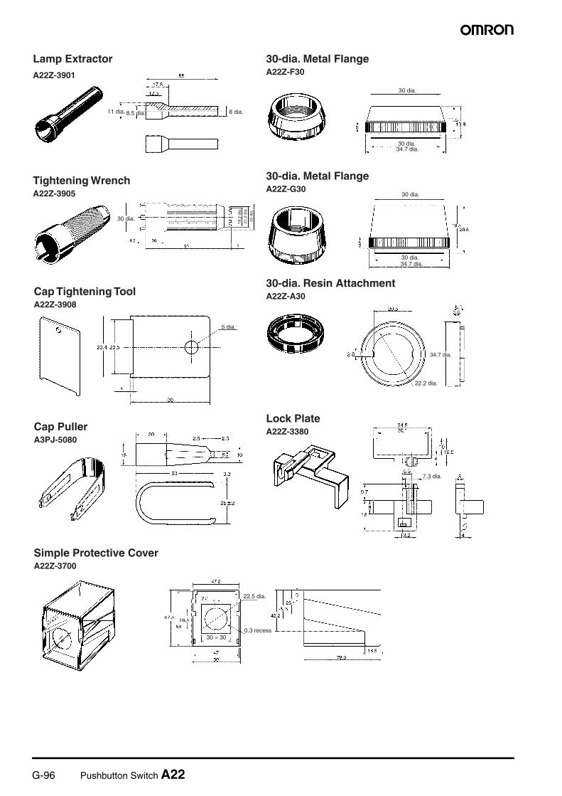
30-dia. Metal Flange Flat, projecting A22Z-F30 Use instead of the standard flange when mounting into a panel with a 30-dia. hole. For details of mount-ing hole dimensions, refer to the corresponding section for the A30.
Full guard A22Z-G30
30-dia. Resin Attach-ment
Round A22Z-A30 Use when mounting to a panel with a 30-dia. hole. For details, re-fer to page 96.
Lock Plate --- A22Z-3380 Use to fix the lever on the Switch.
Simple Protective Cover --- A11Z-3700 Prevents foreign matter entering into the Switch from the back of the panel.
Item Appearance Classification Model Remarks
For A22 For M22
Pushbutton Switch A22 G-89
Pu
shb
utt
on
Sw
itch
es
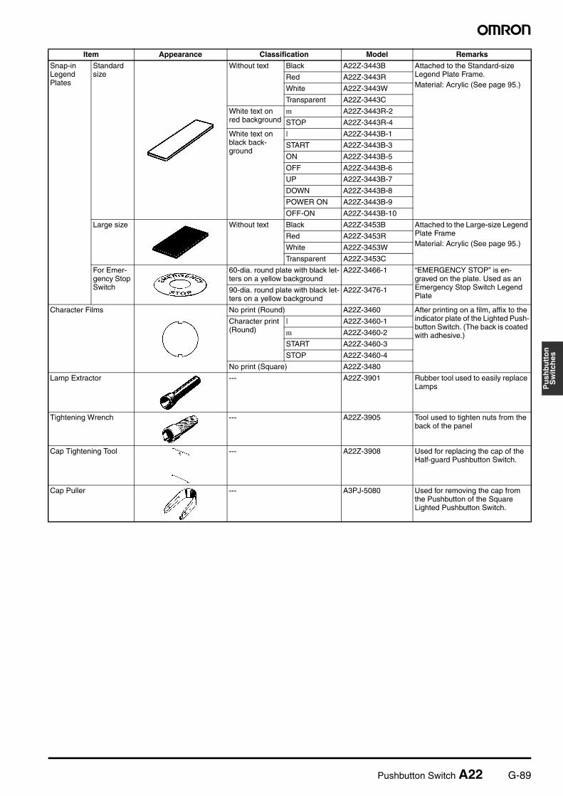
Snap-in Legend Plates
Standard size
Without text Black A22Z-3443B Attached to the Standard-size Legend Plate Frame.Material: Acrylic (See page 95.)
Red A22Z-3443R
White A22Z-3443W
Transparent A22Z-3443C
White text on red background
m A22Z-3443R-2
STOP A22Z-3443R-4
White text on black back-ground
| A22Z-3443B-1
START A22Z-3443B-3
ON A22Z-3443B-5
OFF A22Z-3443B-6
UP A22Z-3443B-7
DOWN A22Z-3443B-8
POWER ON A22Z-3443B-9
OFF-ON A22Z-3443B-10
Large size Without text Black A22Z-3453B Attached to the Large-size Legend Plate FrameMaterial: Acrylic (See page 95.)
Red A22Z-3453R
White A22Z-3453W
Transparent A22Z-3453C
For Emer-gency Stop Switch
60-dia. round plate with black let-ters on a yellow background
A22Z-3466-1 “EMERGENCY STOP” is en-graved on the plate. Used as an Emergency Stop Switch Legend Plate
90-dia. round plate with black let-ters on a yellow background
A22Z-3476-1
Character Films No print (Round) A22Z-3460 After printing on a film, affix to the indicator plate of the Lighted Push-button Switch. (The back is coated with adhesive.)
Character print (Round)
| A22Z-3460-1
m A22Z-3460-2
START A22Z-3460-3
STOP A22Z-3460-4
No print (Square) A22Z-3480
Lamp Extractor --- A22Z-3901 Rubber tool used to easily replace Lamps
Tightening Wrench --- A22Z-3905 Tool used to tighten nuts from the back of the panel
Cap Tightening Tool --- A22Z-3908 Used for replacing the cap of the Half-guard Pushbutton Switch.
Cap Puller --- A3PJ-5080 Used for removing the cap from the Pushbutton of the Square Lighted Pushbutton Switch.
Item Appearance Classification Model Remarks
G-90 Pushbutton Switch A22
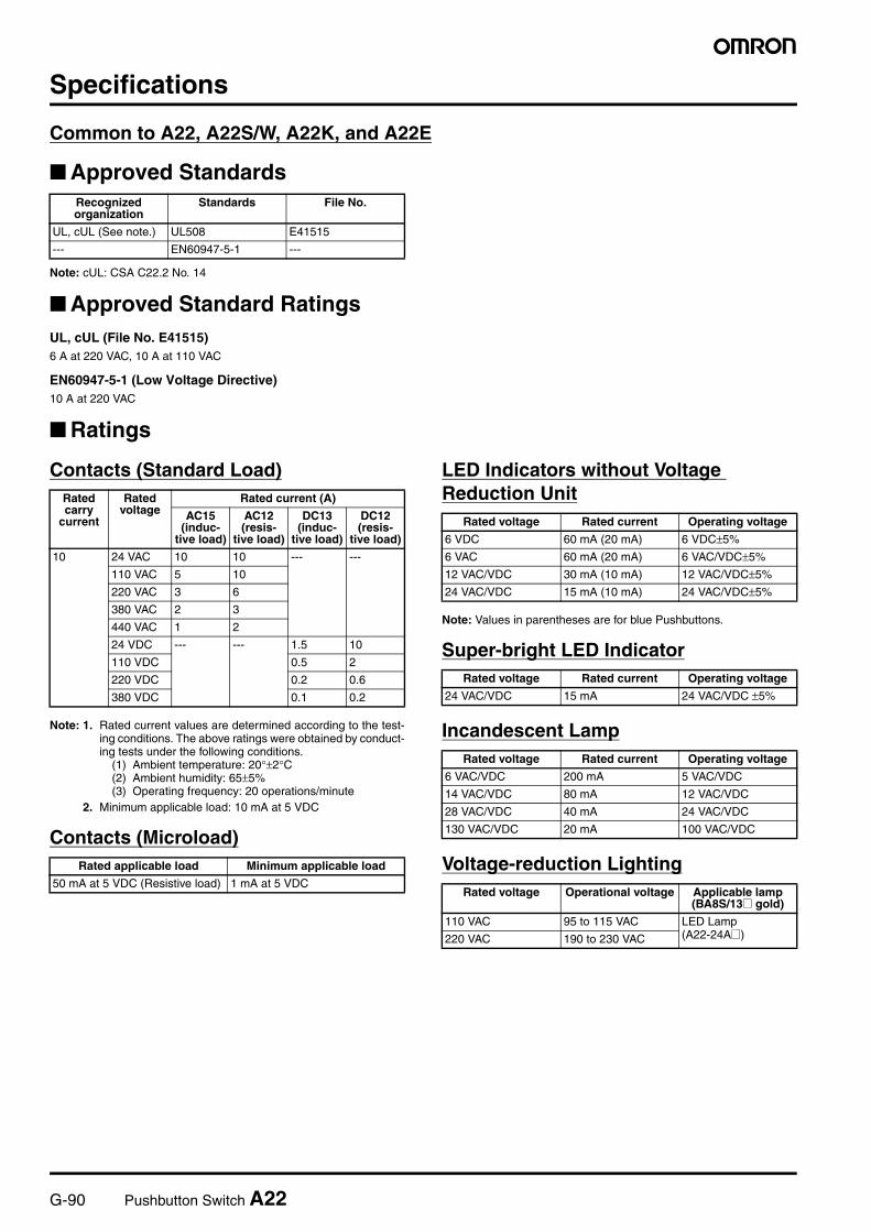
Specifications
Common to A22, A22S/W, A22K, and A22E
Approved Standards
Note: cUL: CSA C22.2 No. 14
Approved Standard RatingsUL, cUL (File No. E41515)6 A at 220 VAC, 10 A at 110 VAC
EN60947-5-1 (Low Voltage Directive)10 A at 220 VAC
Ratings
Contacts (Standard Load)
Note: 1. Rated current values are determined according to the test-ing conditions. The above ratings were obtained by conduct-ing tests under the following conditions.
(1) Ambient temperature: 20°±2°C(2) Ambient humidity: 65±5%(3) Operating frequency: 20 operations/minute
2. Minimum applicable load: 10 mA at 5 VDC
Contacts (Microload)
LED Indicators without Voltage Reduction Unit
Note: Values in parentheses are for blue Pushbuttons.
Super-bright LED Indicator
Incandescent Lamp
Voltage-reduction Lighting
Recognized organization
Standards File No.
UL, cUL (See note.) UL508 E41515
--- EN60947-5-1 ---
Rated carry
current
Rated voltage
Rated current (A)
AC15 (induc-
tive load)
AC12 (resis-
tive load)
DC13 (induc-
tive load)
DC12 (resis-
tive load)
10 24 VAC 10 10 --- ---
110 VAC 5 10
220 VAC 3 6
380 VAC 2 3
440 VAC 1 2
24 VDC --- --- 1.5 10
110 VDC 0.5 2
220 VDC 0.2 0.6
380 VDC 0.1 0.2
Rated applicable load Minimum applicable load
50 mA at 5 VDC (Resistive load) 1 mA at 5 VDC
Rated voltage Rated current Operating voltage
6 VDC 60 mA (20 mA) 6 VDC±5%
6 VAC 60 mA (20 mA) 6 VAC/VDC±5%
12 VAC/VDC 30 mA (10 mA) 12 VAC/VDC±5%
24 VAC/VDC 15 mA (10 mA) 24 VAC/VDC±5%
Rated voltage Rated current Operating voltage
24 VAC/VDC 15 mA 24 VAC/VDC ±5%
Rated voltage Rated current Operating voltage
6 VAC/VDC 200 mA 5 VAC/VDC
14 VAC/VDC 80 mA 12 VAC/VDC
28 VAC/VDC 40 mA 24 VAC/VDC
130 VAC/VDC 20 mA 100 VAC/VDC
Rated voltage Operational voltage Applicable lamp (BA8S/13@ gold)
110 VAC 95 to 115 VAC LED Lamp (A22-24A@)220 VAC 190 to 230 VAC
Pushbutton Switch A22 G-91
Pu
shb
utt
on
Sw
itch
es
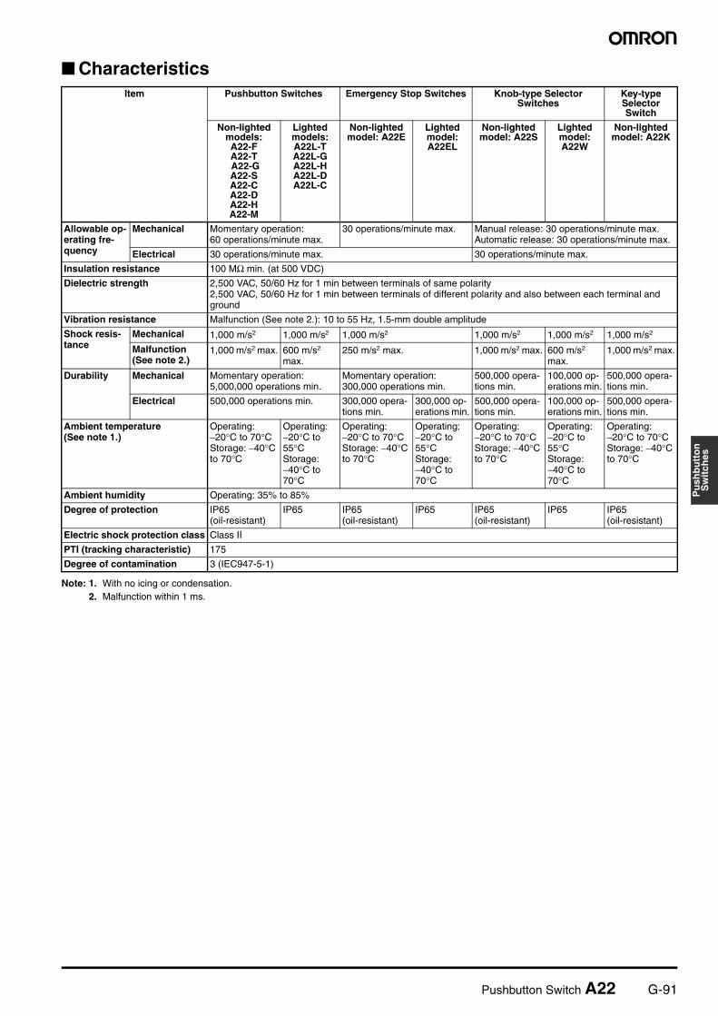
Characteristics
Note: 1. With no icing or condensation.2. Malfunction within 1 ms.
Item Pushbutton Switches Emergency Stop Switches Knob-type Selector Switches
Key-type Selector Switch
Non-lighted models: A22-F A22-T A22-G A22-S A22-C A22-D A22-H A22-M
Lighted models: A22L-T A22L-G A22L-H A22L-D A22L-C
Non-lighted model: A22E
Lighted model: A22EL
Non-lighted model: A22S
Lighted model: A22W
Non-lighted model: A22K
Allowable op-erating fre-quency
Mechanical Momentary operation: 60 operations/minute max.
30 operations/minute max. Manual release: 30 operations/minute max.Automatic release: 30 operations/minute max.
Electrical 30 operations/minute max. 30 operations/minute max.
Insulation resistance 100 MΩ min. (at 500 VDC)
Dielectric strength 2,500 VAC, 50/60 Hz for 1 min between terminals of same polarity2,500 VAC, 50/60 Hz for 1 min between terminals of different polarity and also between each terminal and ground
Vibration resistance Malfunction (See note 2.): 10 to 55 Hz, 1.5-mm double amplitude
Shock resis-tance
Mechanical 1,000 m/s2 1,000 m/s2 1,000 m/s2 1,000 m/s2 1,000 m/s2 1,000 m/s2
Malfunction (See note 2.)
1,000 m/s2 max. 600 m/s2 max.
250 m/s2 max. 1,000 m/s2 max. 600 m/s2 max.
1,000 m/s2 max.
Durability Mechanical Momentary operation: 5,000,000 operations min.
Momentary operation: 300,000 operations min.
500,000 opera-tions min.
100,000 op-erations min.
500,000 opera-tions min.
Electrical 500,000 operations min. 300,000 opera-tions min.
300,000 op-erations min.
500,000 opera-tions min.
100,000 op-erations min.
500,000 opera-tions min.
Ambient temperature (See note 1.)
Operating: −20°C to 70°CStorage: −40°C to 70°C
Operating: −20°C to 55°CStorage: −40°C to 70°C
Operating: −20°C to 70°CStorage: −40°C to 70°C
Operating: −20°C to 55°CStorage: −40°C to 70°C
Operating: −20°C to 70°CStorage: −40°C to 70°C
Operating: −20°C to 55°CStorage: −40°C to 70°C
Operating: −20°C to 70°CStorage: −40°C to 70°C
Ambient humidity Operating: 35% to 85%
Degree of protection IP65 (oil-resistant)
IP65 IP65 (oil-resistant)
IP65 IP65 (oil-resistant)
IP65 IP65 (oil-resistant)
Electric shock protection class Class II
PTI (tracking characteristic) 175
Degree of contamination 3 (IEC947-5-1)
G-92 Pushbutton Switch A22
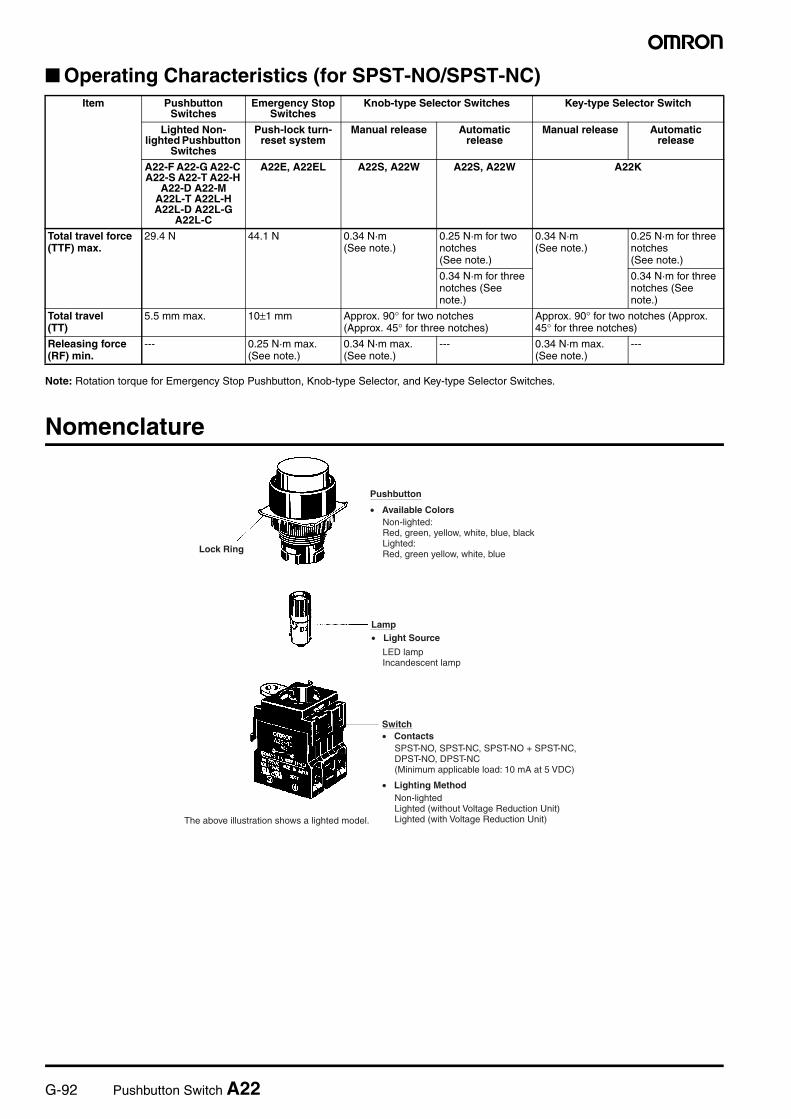
Operating Characteristics (for SPST-NO/SPST-NC)
Note: Rotation torque for Emergency Stop Pushbutton, Knob-type Selector, and Key-type Selector Switches.
Nomenclature
Item Pushbutton Switches
Emergency Stop Switches
Knob-type Selector Switches Key-type Selector Switch
Lighted Non-lighted Pushbutton
Switches
Push-lock turn-reset system
Manual release Automatic release
Manual release Automatic release
A22-F A22-G A22-C A22-S A22-T A22-H
A22-D A22-M A22L-T A22L-H A22L-D A22L-G
A22L-C
A22E, A22EL A22S, A22W A22S, A22W A22K
Total travel force(TTF) max.
29.4 N 44.1 N 0.34 N·m(See note.)
0.25 N·m for two notches(See note.)
0.34 N·m(See note.)
0.25 N·m for three notches(See note.)
0.34 N·m for three notches (See note.)
0.34 N·m for three notches (See note.)
Total travel(TT)
5.5 mm max. 10±1 mm Approx. 90° for two notches (Approx. 45° for three notches)
Approx. 90° for two notches (Approx. 45° for three notches)
Releasing force (RF) min.
--- 0.25 N·m max.(See note.)
0.34 N·m max.(See note.)
--- 0.34 N·m max.(See note.)
---
Pushbutton
• Available Colors
Lamp• Light Source
Switch• Contacts
• Lighting Method
The above illustration shows a lighted model.
Lock Ring
Non-lighted: Red, green, yellow, white, blue, black Lighted: Red, green yellow, white, blue
LED lamp Incandescent lamp
SPST-NO, SPST-NC, SPST-NO + SPST-NC, DPST-NO, DPST-NC (Minimum applicable load: 10 mA at 5 VDC)
Non-lighted Lighted (without Voltage Reduction Unit) Lighted (with Voltage Reduction Unit)
Pushbutton Switch A22 G-93
Pu
shb
utt
on
Sw
itch
es
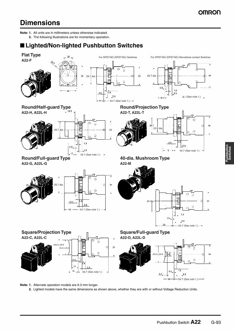
DimensionsNote: 1. All units are in millimeters unless otherwise indicated.
2. The following illustrations are for momentary operation.
Lighted/Non-lighted Pushbutton Switches
Note: 1. Alternate operation models are 9.3 mm longer.2. Lighted models have the same dimensions as shown above, whether they are with or without Voltage Reduction Units.
29.8 x 29.8
29.8 x 29.8
25.6 x 25.6
Flat TypeA22-F
Round/Half-guard TypeA22-H, A22L-H
Round/Projection TypeA22-T, A22L-T
(See note 1.)
29.7 dia. 29.7 dia.
For SPST-NO (SPST-NC) Switches For DPST-NO (DPST-NC) Monoblock-contact Switches
29.7 dia.23.9 dia.
40-dia. Mushroom TypeA22-M
29.7 dia.
Round/Full-guard TypeA22-G, A22L-G
54.7 (See note 1.)
40 dia.
Square/Full-guard TypeA22-D, A22L-D
54.7 (See note 1.)
54.7 (See note 1.)
54.7 (See note 1.)
54.7 (See note 1.)
54.7 (See note 1.)
Square/Projection TypeA22-C, A22L-C
54.7 (See note 1.)
G-94 Pushbutton Switch A22
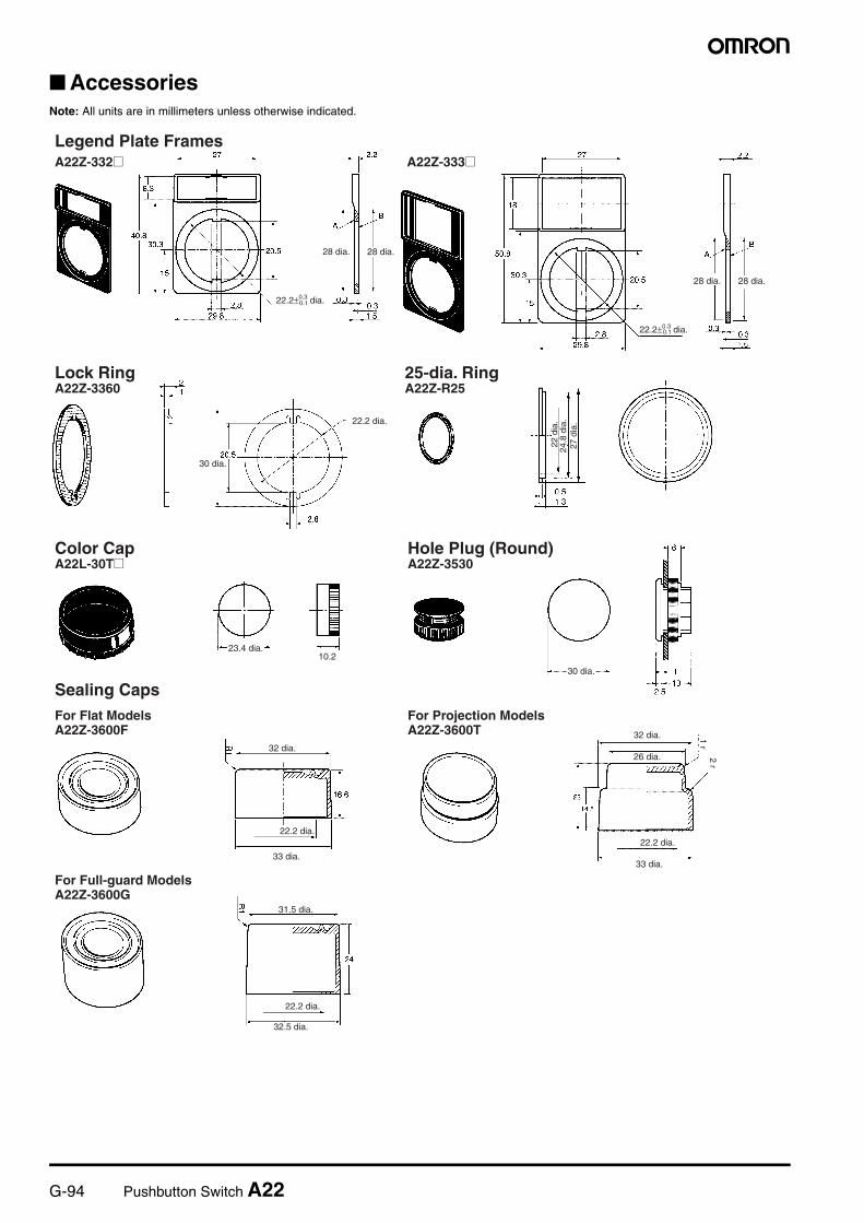
AccessoriesNote: All units are in millimeters unless otherwise indicated.
10.2
Legend Plate FramesA22Z-332@ A22Z-333@
Lock RingA22Z-3360
22.2 dia.
25-dia. RingA22Z-R25
Color CapA22L-30T@
23.4 dia.
Hole Plug (Round)A22Z-3530
30 dia.
22.2 dia.
33 dia.
32 dia.
22.2 dia.
33 dia.
32 dia.
26 dia.
31.5 dia.
22.2 dia.
32.5 dia.
Sealing Caps
22.2±0.3 dia.0.1
22.2±0.3 dia.0.1
30 dia.
28 dia.28 dia.
28 dia. 28 dia.
22 d
ia.
24.8
dia
.27
dia
.
For Flat Models A22Z-3600F
For Projection Models A22Z-3600T
For Full-guard Models A22Z-3600G
1 r2 r
Pushbutton Switch A22 G-95
Pu
shb
utt
on
Sw
itch
es
21.5 x 21.5±0.20.3
t0.22
t0.22
Three-throw SpacerA22Z-3003
Metallic Bezel Rings
29.7±0.3 dia.
Snap-in Legend Plates
For Emergency-stop Models
22.2 dia.
90 dia.
A22Z-3466-1 (60 dia.)
22.2 dia.
60 dia.
Character Film
14.2 dia.
13.7 dia.
12.9 dia.
28.7 dia.24+0.2 dia.−0
29.7±0.3 dia.
28.7 dia.
24+0.2 dia.−0
19.4+0.1 dia.−0.2
A22Z-3476-1 (90 dia.)
Black letters
Yellow
Black letters
Yellow
For Flat/Projection Models A22Z-3580
For Full-guard Models A22Z-3582
For Standard Models A22L-3443@-@
For Large Models A22Z-3453@
For Round Models A22Z-3460-@
For Square Models A22Z-3480
G-96 Pushbutton Switch A22
30 × 30
Lamp ExtractorA22Z-3901
Tightening WrenchA22Z-3905
Cap Tightening ToolA22Z-3908
Cap PullerA3PJ-5080
Simple Protective CoverA22Z-3700
30-dia. Metal FlangeA22Z-F30
30-dia. Metal FlangeA22Z-G30
30-dia. Resin AttachmentA22Z-A30
Lock PlateA22Z-3380
22.5 dia.
0.3 recess
11 dia. 8.5 dia.
30 dia.34.7 dia.
30 dia.
19.2
dia
.
21.2
dia
.
25 d
ia.
30 dia.34.7 dia.
30 dia.
30 dia.
5 dia.
22.2 dia.
34.7 dia.
7.3 dia.
8 dia.
Pushbutton Switch A22 G-97
Pu
shb
utt
on
Sw
itch
es
Control Box (Enclosure)A22Z-B10@
A22Z-B102 (Two Holes)
A22Z-B103 (Three Holes)
21 dia.
22.1+0.3 dia.−0.1
Cable Port Hole (Top View)
16±1 dia.
−0.1Two, 22.1+0.3 dia.
21 dia.
Cable Port Hole (Top View)
16±1 dia.
−0.1Three, 22.1+0.3 dia.
21 dia.
Cable Port Hole (Top View)
16±1 dia.
Panel Mounting Hole
Four, 4x38 tapping screws
(10x36) 0.6-mm concave surface
(Lead cable hole)
(Lead cable hole) Two mounting holes
(Lead cable hole)
Four, 4x38 tapping screws
Four, 4x38 tapping screws
(10x36) 0.6-mm concave surface
(Lead cable hole)
(Lead cable hole)
(10x36) 0.6-mm concave surface
A22Z-B101 (One Hole) A22Z-B101Y
(Lead cable hole)
Two mounting holes
Two mounting holes
G-98 Pushbutton Switch A22
Terminal Arrangement (Bottom View)Non-lighted (SPST-NO + SPST-NC) Lighted (SPST-NO + SPST-NC) Non-lighted (DPST-NO + DPST-NC)
A22Z-B202 (Two Holes)
A22Z-B203 (Three Holes)
Cable Port Hole (Top View)
Cable Port Hole (Top View)
Cable Port Hole (Top View)
Panel Mounting Hole
Four, M4 Phillips binding screws22.1 dia.
Cover (gray)
Two, 21 dia.
Case (black)
Cover (gray)
Two, 21 dia.
Case (black)
Two, 22.1 dia.
Four, M4 Phillips binding screws
Four, M4 Phillips binding screws
Three, 22.1 dia.
(10×36) 0.6-mm concave surface
Cover (gray)
Two, 21 dia.
Case (black)
A22Z-B201 (One Hole) A22Z-B201Y
(10×36) 0.6-mm concave surface
21 dia. (both sides)
Two, 19 dia. (base)
Two mounting holes
(10×36) 0.6-mm concave surface
21 dia. (both sides)
Two, 19 dia. (base)
Two mounting holes
21 dia. (both sides)
Two, 19 dia. (base)
Two mounting holes
Switch Blocks
M3.5 screw
Switch Blocks
Lamp socket
Switch Blocks
Pushbutton Switch A22 G-99
Pu
shb
utt
on
Sw
itch
es
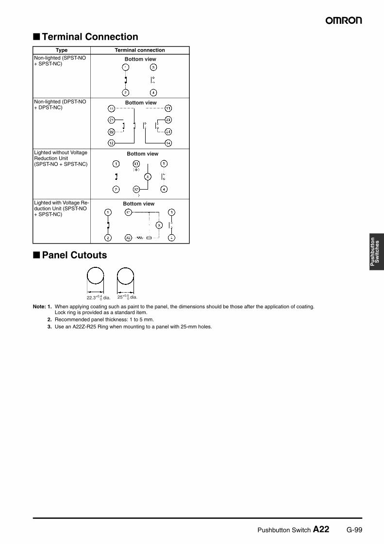
Terminal Connection
Panel Cutouts
Note: 1. When applying coating such as paint to the panel, the dimensions should be those after the application of coating.Lock ring is provided as a standard item.
2. Recommended panel thickness: 1 to 5 mm.3. Use an A22Z-R25 Ring when mounting to a panel with 25-mm holes.
Type Terminal connection
Non-lighted (SPST-NO + SPST-NC)
Non-lighted (DPST-NO + DPST-NC)
Lighted without Voltage Reduction Unit(SPST-NO + SPST-NC)
Lighted with Voltage Re-duction Unit (SPST-NO + SPST-NC)
Bottom view
Bottom view
Bottom view
Bottom view
22.3+0.4 dia.0 25+0.5 dia.0
G-100 Pushbutton Switch A22
Installation
Common to A22, A22S/W, A22K, M22, and A22E
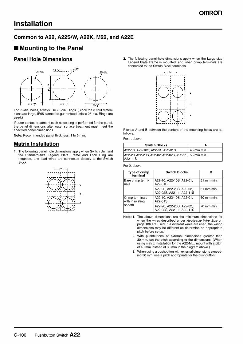
Mounting to the Panel
Panel Hole Dimensions
For 25-dia. holes, always use 25-dia. Rings. (Since the cutout dimen-sions are large, IP65 cannot be guaranteed unless 25-dia. Rings areused.)
If outer surface treatment such as coating is performed for the panel,the panel dimensions after outer surface treatment must meet thespecified panel dimensions.
Note: Recommended panel thickness: 1 to 5 mm.
Matrix Installation1. The following panel hole dimensions apply when Switch Unit and
the Standard-size Legend Plate Frame and Lock Ring aremounted, and lead wires are connected directly to the SwitchBlock.
2. The following panel hole dimensions apply when the Large-sizeLegend Plate Frame is mounted, and when crimp terminals areconnected to the Switch Block terminals.
Pitches A and B between the centers of the mounting holes are asfollows:
For 1. above:
For 2. above:
Note: 1. The above dimensions are the minimum dimensions forwhen the wires described under Applicable Wire Size onpage 106 are used. If a different wires are used, the wiringdimensions may be different so determine an appropriatepitch before setup.
2. With pushbuttons of external dimensions greater than30 mm, set the pitch according to the dimensions. (Whenusing matrix installation for the A22-M@, mount with a pitchof 40 mm instead of 30 mm in the diagram above.)
3. When using a pushbutton with external dimensions exceed-ing 30 mm, use a pitch appropriate for the pushbutton.
22 dia. 25 dia.
A
Switch Blocks A
A22-10, A22-10S, A22-01, A22-01S 45 mm min.
A22-20, A22-20S, A22-02, A22-02S, A22-11, A22-11S
55 mm min.
Type of crimp terminal
Switch Blocks B
Bare crimp termi-nals
A22-10, A22-10S, A22-01, A22-01S
51 mm min.
A22-20, A22-20S, A22-02, A22-02S, A22-11, A22-11S
61 mm min.
Crimp terminals with insulating sheath
A22-10, A22-10S, A22-01, A22-01S
60 mm min.
A22-20, A22-20S, A22-02, A22-02S, A22-11, A22-11S
70 mm min.
B
Pushbutton Switch A22 G-101
Pu
shb
utt
on
Sw
itch
es
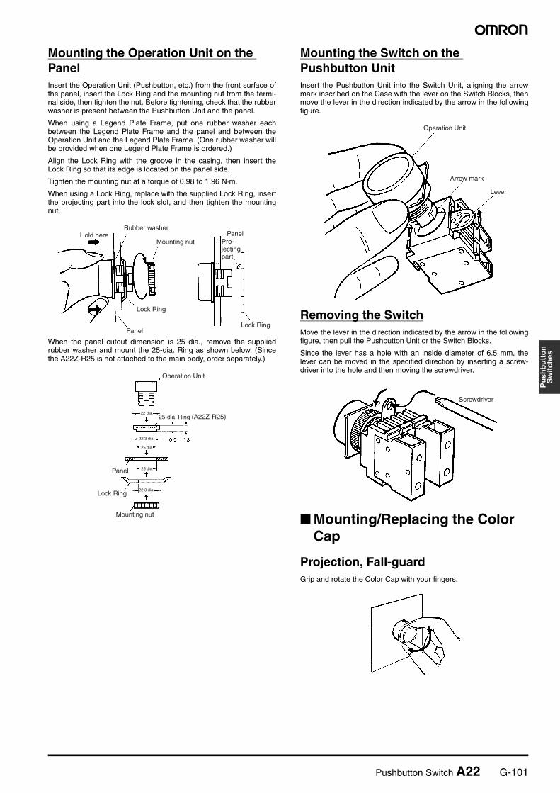
Mounting the Operation Unit on the PanelInsert the Operation Unit (Pushbutton, etc.) from the front surface ofthe panel, insert the Lock Ring and the mounting nut from the termi-nal side, then tighten the nut. Before tightening, check that the rubberwasher is present between the Pushbutton Unit and the panel.
When using a Legend Plate Frame, put one rubber washer eachbetween the Legend Plate Frame and the panel and between theOperation Unit and the Legend Plate Frame. (One rubber washer willbe provided when one Legend Plate Frame is ordered.)
Align the Lock Ring with the groove in the casing, then insert theLock Ring so that its edge is located on the panel side.
Tighten the mounting nut at a torque of 0.98 to 1.96 N·m.
When using a Lock Ring, replace with the supplied Lock Ring, insertthe projecting part into the lock slot, and then tighten the mountingnut.
When the panel cutout dimension is 25 dia., remove the suppliedrubber washer and mount the 25-dia. Ring as shown below. (Sincethe A22Z-R25 is not attached to the main body, order separately.)
Mounting the Switch on the Pushbutton UnitInsert the Pushbutton Unit into the Switch Unit, aligning the arrowmark inscribed on the Case with the lever on the Switch Blocks, thenmove the lever in the direction indicated by the arrow in the followingfigure.
Removing the SwitchMove the lever in the direction indicated by the arrow in the followingfigure, then pull the Pushbutton Unit or the Switch Blocks.
Since the lever has a hole with an inside diameter of 6.5 mm, thelever can be moved in the specified direction by inserting a screw-driver into the hole and then moving the screwdriver.
Mounting/Replacing the Color Cap
Projection, Fall-guardGrip and rotate the Color Cap with your fingers.
Hold hereMounting nut
Lock Ring
Rubber washerPanel
PanelLock Ring
Pro-jecting part
Operation Unit
25-dia. Ring (A22Z-R25)
Panel
Lock Ring
Mounting nut
22.3 dia.
25 dia.
25 dia.
22 dia.
22.3 dia.
Operation Unit
Arrow mark
Lever
Screwdriver
G-102 Pushbutton Switch A22
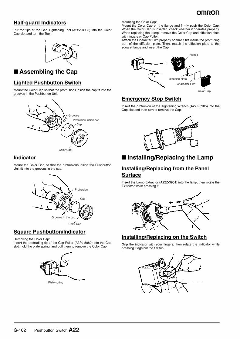
Half-guard IndicatorsPut the tips of the Cap Tightening Tool (A22Z-3908) into the ColorCap slot and turn the Tool.
Assembling the Cap
Lighted Pushbutton SwitchMount the Color Cap so that the protrusions inside the cap fit into thegrooves in the Pushbutton Unit.
IndicatorMount the Color Cap so that the protrusions inside the PushbuttonUnit fit into the grooves in the cap.
Square Pushbutton/IndicatorRemoving the Color Cap:Insert the protruding tip of the Cap Puller (A3PJ-5080) into the Capslot, hold the plate spring, and pull them to remove the Color Cap.
Mounting the Color Cap:Mount the Color Cap on the flange and firmly push the Color Cap.When the Color Cap is inserted, check whether it operates properly.When replacing the Lamp, remove the Color Cap and diffusion platewith fingers or Cap Puller.Attach the Character Film properly so that it fits inside the protrudingpart of the diffusion plate. Then, match the diffusion plate to thesquare flange and insert the Cap.
Emergency Stop SwitchInsert the protrusion of the Tightening Wrench (A22Z-3905) into theCap slot and then turn to remove the Cap.
Installing/Replacing the Lamp
Installing/Replacing from the Panel SurfaceInsert the Lamp Extractor (A22Z-3901) into the lamp, then rotate theExtractor while pressing it.
Installing/Replacing on the SwitchGrip the indicator with your fingers, then rotate the indicator whilepressing it against the Switch.
Grooves
Protrusion inside cap
Cap
Color Cap
Protrusion
Cap
Grooves in the cap
Color Cap
Plate spring
Flange
Diffusion plate
Character Film
Color Cap
Pushbutton Switch A22 G-103
Pu
shb
utt
on
Sw
itch
es
Control Box (Enclosure)
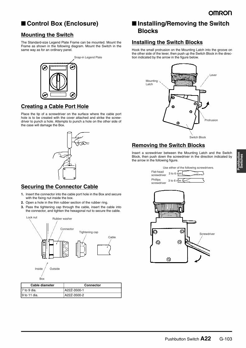
Mounting the SwitchThe Standard-size Legend Plate Frame can be mounted. Mount theFrame as shown in the following diagram. Mount the Switch in thesame way as for an ordinary panel.
Creating a Cable Port HolePlace the tip of a screwdriver on the surface where the cable porthole is to be created with the cover attached and strike the screw-driver to punch a hole. Attempts to punch a hole on the other side ofthe case will damage the Box.
Securing the Connector Cable1. Insert the connector into the cable port hole in the Box and secure
with the fixing nut inside the box.2. Open a hole in the thin rubber section of the rubber ring.3. Pass the tightening cap through the cable, insert the cable into
the connector, and tighten the hexagonal nut to secure the cable.
Installing/Removing the Switch Blocks
Installing the Switch BlocksHook the small protrusion on the Mounting Latch into the groove onthe other side of the lever, then push up the Switch Block in the direc-tion indicated by the arrow in the figure below.
Removing the Switch BlocksInsert a screwdriver between the Mounting Latch and the SwitchBlock, then push down the screwdriver in the direction indicated bythe arrow in the following figure.
Cable diameter Connector
7 to 9 dia. A22Z-3500-1
9 to 11 dia. A22Z-3500-2
Snap-in Legend Plate
Lock nut Rubber washer
ConnectorTightening cap
Inside Outside
Box
Cable
Lever
Switch Block
Protrusion
Mounting Latch
Use either of the following screwdrivers.
Screwdriver
3 to 6 mm
3 to 6 mm
Flat-head screwdriver
Phillips screwdriver
G-104 Pushbutton Switch A22
Wiring
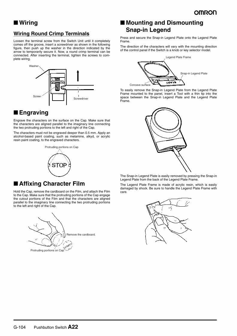
Wiring Round Crimp TerminalsLoosen the terminal screw from the Switch Unit until it completelycomes off the groove, insert a screwdriver as shown in the followingfigure, then push up the washer in the direction indicated by thearrow to temporarily secure it. Now, a round crimp terminal can beconnected. After inserting the terminal, tighten the screws to com-plete wiring.
EngravingEngrave the characters on the surface on the Cap. Make sure thatthe characters are aligned parallel to the imaginary line connectingthe two protruding portions to the left and right of the Cap.
The characters must not be engraved deeper than 0.5 mm. Apply analcohol-based paint coating, such as melamine, alkyd, or acrylicresin paint coating, to the engraved characters.
Affixing Character FilmHold the Cap, remove the cardboard on the Film, and attach the Filmto the Cap. Make sure that the protruding portions of the Cap engagethe cutout portions of the Film and that the characters are alignedparallel to the imaginary line connecting the two protruding portionsto the left and right of the Cap.
Mounting and Dismounting Snap-in Legend
Press and secure the Snap-in Legend Plate onto the Legend PlateFrame.
The direction of the characters will vary with the mounting directionof the control panel if the Switch is a knob or key selector model.
To easily remove the Snap-in Legend Plate from the Legend PlateFrame mounted to the panel, insert a Tool with a thin tip into thespace between the Snap-in Legend Plate and the Legend PlateFrame.
The Snap-in Legend Plate is easily removed by pressing the Snap-inLegend Plate from the back of the Legend Plate Frame.
The Legend Plate Frame is made of acrylic resin, which is easilydamaged by shock. Be sure to handle the Legend Plate Frame withcare.
Screw
Washer
Screwdriver
Protruding portions on Cap
Protruding portions on Cap
Remove the cardboard.
Legend Plate Frame
Snap-in Legend Plate
Concave surface
Pushbutton Switch A22 G-105
Pu
shb
utt
on
Sw
itch
es
Engraving Method
Material: AcrylicEngrave the characters directly on the matted side of the Snap-inLegend Plate.
The characters must be engraved no deeper than 0.5 mm.
Apply alcohol-based paint coating to the engraved characters.
If the Snap-in Legend Plate is transparent, engrave the mirror-writtencharacters on the back of the Snap-in Legend Plate and apply paintcoating to the characters. Then apply paint coating of a differentcolor to the remaining part of the Snap-in Legend Plate.
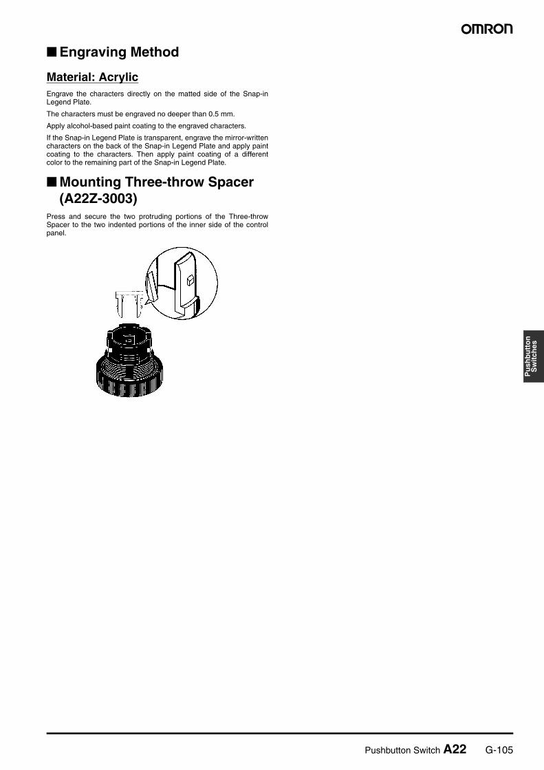
Mounting Three-throw Spacer (A22Z-3003)
Press and secure the two protruding portions of the Three-throwSpacer to the two indented portions of the inner side of the controlpanel.
G-106 Pushbutton Switch A22
Precautions
Common to A22, A22S/W, A22K, M22, and A22E
!WARNINGDo not apply a voltage between the incandescent lamp and theterminal that is greater than the rated voltage. If the incandescentlamp is broken, the Operation Units may pop out. Always turn OFF the power and wait for 10 minutes before replac-ing the incandescent lamp. If the lamp is replaced immediately af-ter the power is turned OFF, the remaining heat may cause burns.
Correct Use
MountingAlways make sure that the power is turned OFF before mounting,removing, or wiring the Switch, or performing maintenance.
Do not tighten the mounting ring more than necessary using toolssuch as pointed-nose pliers. Doing so will damage the mounting ring.The tightening torque is 0.98 to 1.96 N·m.
Recommended panel thickness: 1 to 5 mm.
WiringAfter wiring the Switch, maintain an appropriate clearance andcreepage distance.
When DC-specific LEDs are used, wire the Switch so that the X1 ter-minal is positive.
Terminal screws must be Phillips or slotted M3.5 screws with asquare washer.
The tightening torque is 1.08 to 1.27 N·m.
Single wires, stranded wires, and crimp terminals can be connectedto the Switch.
Applicable Wire SizeStranded wire: 2 mm2 max.Solid wire: 1.6 dia. max.
Operating EnvironmentThe IP65 model is designed with a degree of protection so that it willnot sustain damage if it is subjected to water from any direction to thefront of the panel.
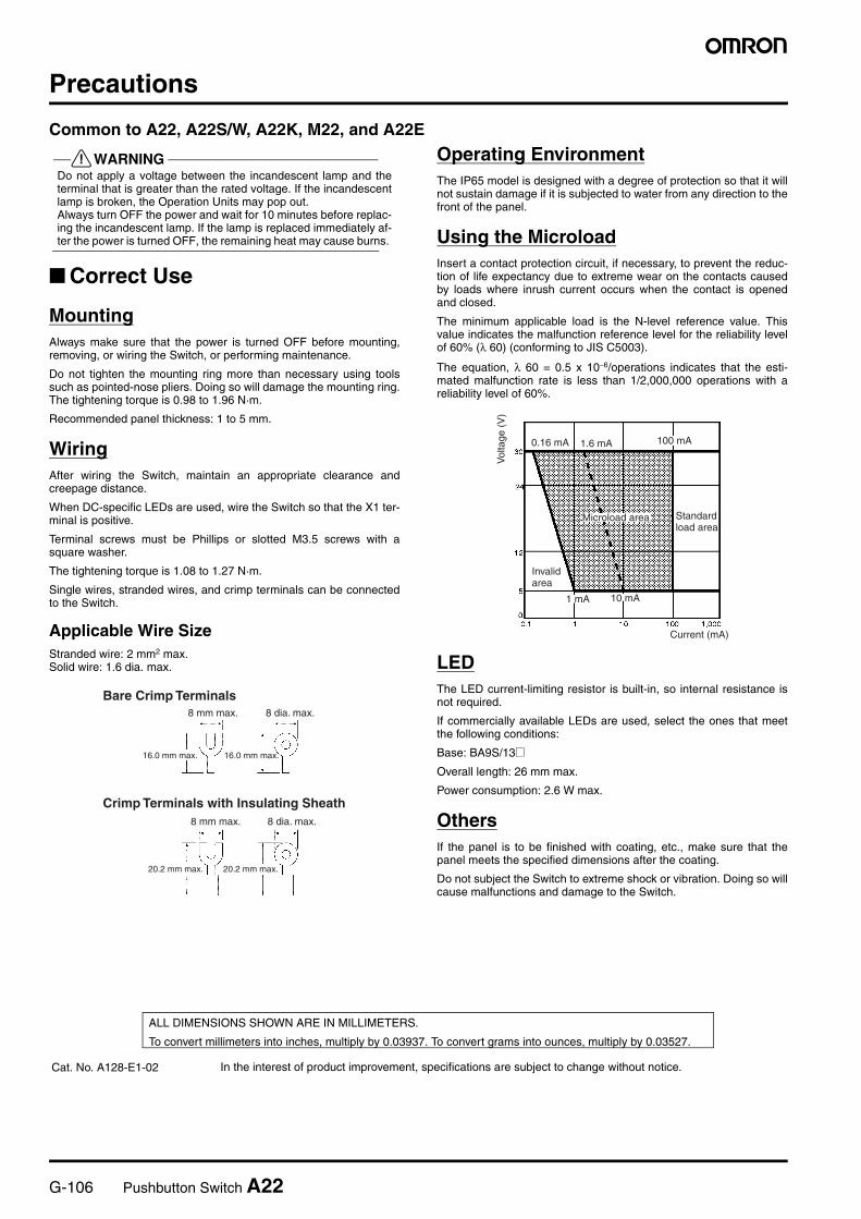
Using the MicroloadInsert a contact protection circuit, if necessary, to prevent the reduc-tion of life expectancy due to extreme wear on the contacts causedby loads where inrush current occurs when the contact is openedand closed.
The minimum applicable load is the N-level reference value. Thisvalue indicates the malfunction reference level for the reliability levelof 60% (λ 60) (conforming to JIS C5003).
The equation, λ 60 = 0.5 x 10⁻⁶/operations indicates that the esti-mated malfunction rate is less than 1/2,000,000 operations with areliability level of 60%.
LEDThe LED current-limiting resistor is built-in, so internal resistance isnot required.
If commercially available LEDs are used, select the ones that meetthe following conditions:
Base: BA9S/13@Overall length: 26 mm max.
Power consumption: 2.6 W max.
OthersIf the panel is to be finished with coating, etc., make sure that thepanel meets the specified dimensions after the coating.
Do not subject the Switch to extreme shock or vibration. Doing so willcause malfunctions and damage to the Switch.
Bare Crimp Terminals8 mm max.
16.0 mm max. 16.0 mm max.
8 dia. max.
Crimp Terminals with Insulating Sheath8 mm max.
20.2 mm max. 20.2 mm max.
8 dia. max.
0.16 mA 1.6 mA 100 mA
10 mA1 mA
Vol
tage
(V
)
Current (mA)
Microload area Standard load area
Invalid area
In the interest of product improvement, specifications are subject to change without notice.
ALL DIMENSIONS SHOWN ARE IN MILLIMETERS.
To convert millimeters into inches, multiply by 0.03937. To convert grams into ounces, multiply by 0.03527.
Cat. No. A128-E1-02