insta eib h210x297-1 - downloads.jung.de · product documentation knx room controller display...
TRANSCRIPT
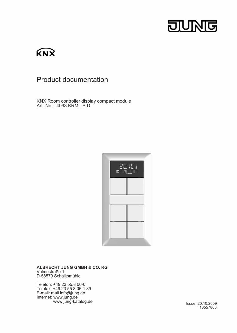
Product documentation
KNX Room controller display compact module Art.-No.: 4093 KRM TS D
ALBRECHT JUNG GMBH & CO. KG Volmestraße 1 D-58579 Schalksmühle
Telefon: +49.23 55.8 06-0 Telefax: +49.23 55.8 06-1 89 E-mail: [email protected] Internet: www.jung.de www.jung-katalog.de Issue: 20.10.2009
13557800
Art.-No.: 4093 KRM TS D
Content
1 Product definition 4 ................................................................................................................
1.1 Product catalogue 4 ........................................................................................................... 1.2 Function 4 .......................................................................................................................... 1.3 Accessories 6 ....................................................................................................................
2 Installation, electrical connection and operation 7 .............................................................
2.1 Safety instructions 7 .......................................................................................................... 2.2 Device components 8 ........................................................................................................ 2.3 Fitting and electrical connection 9 ..................................................................................... 2.4 Commissioning 13 ............................................................................................................. 2.5 Operation 15 ......................................................................................................................
2.5.1 Basic display 16 ......................................................................................................... 2.5.2 Second operating level 17 ..........................................................................................
3 Technical data 26 ....................................................................................................................
4 Software description 27 .........................................................................................................
4.1 Software specification 27 ................................................................................................... 4.2 Software "Continuous controller module 3gang 146A11" 28 .............................................
4.2.1 Scope of functions 28 ................................................................................................. 4.2.2 Notes on software 31 ................................................................................................. 4.2.3 Object table 32 ...........................................................................................................
4.2.3.1 Object table, pushbutton sensor function section 32 .......................................... 4.2.3.2 Object table, controller function section 45 ......................................................... 4.2.3.3 Display object table 62 ........................................................................................
4.2.4 Functional description 66 ........................................................................................... 4.2.4.1 Pushbutton sensor 66 .........................................................................................
4.2.4.1.1 Operation concept and button evaluation 66 .............................................. 4.2.4.1.2 "Switching" function 73 ................................................................................ 4.2.4.1.3 "Dimming" function 74 ................................................................................. 4.2.4.1.4 "Venetian blind" function 76 ........................................................................ 4.2.4.1.5 Value transmitter function 80 ...................................................................... 4.2.4.1.6 "Scene extension" function 83 ..................................................................... 4.2.4.1.7 Function "2-channel operation" 84 .............................................................. 4.2.4.1.8 "Controller extension" function 86 ............................................................... 4.2.4.1.9 "Fan control" function 87 ............................................................................. 4.2.4.1.10 "Controller operating mode" function 88 ...................................................... 4.2.4.1.11 "Setpoint shift" function 89 .......................................................................... 4.2.4.1.12 "Change in the display reading" function 90 ................................................ 4.2.4.1.13 Status LED 91 ............................................................................................. 4.2.4.1.14 Disabling function 93 ................................................................................... 4.2.4.1.15 Transmission delay 96 ................................................................................ 4.2.4.1.16 Alarm message 97 ......................................................................................
4.2.4.2 Room temperature controller 98 ......................................................................... 4.2.4.2.1 Operating modes and operating mode change-over 98 .............................. 4.2.4.2.2 Control algorithms and calculation of command values 101 ....................... 4.2.4.2.3 Adapting the control algorithms 108 ............................................................ 4.2.4.2.4 Operating mode change-over 111 .............................................................. 4.2.4.2.5 Temperature setpoints 120 ......................................................................... 4.2.4.2.6 Room temperature measurement 134 ........................................................ 4.2.4.2.7 Command value and status output 137 ...................................................... 4.2.4.2.8 Fan controller 141 ....................................................................................... 4.2.4.2.9 Disable functions of the room temperature controller 148 ........................... 4.2.4.2.10 Valve protection 149 ...................................................................................
4.2.4.3 Room temperature controller extension 150 ....................................................... 4.2.4.3.1 Connection to room temperature controller 150 ..........................................
Product documentation
Page 2 of 241
Art.-No.: 4093 KRM TS D
4.2.4.3.2 Operating functions 153 .............................................................................. 4.2.4.3.3 Display functions 155 .................................................................................. 4.2.4.3.4 Room temperature measurement 157 ........................................................ 4.2.4.3.5 Behaviour after a device restart 158 ...........................................................
4.2.4.4 Light scene function 159 ..................................................................................... 4.2.4.5 Display 162 .........................................................................................................
4.2.4.5.1 Displayed information 162 ........................................................................... 4.2.4.5.2 Display control 165 ......................................................................................
4.2.4.6 Delivery state 168 ............................................................................................... 4.2.5 Parameters 169 ..........................................................................................................
4.2.5.1 General parameters 169 ..................................................................................... 4.2.5.2 Parameter for room temperature measurement 174 .......................................... 4.2.5.3 Parameters on the pushbutton sensor function section 176 ............................... 4.2.5.4 Parameter for the controller function section 211 ............................................... 4.2.5.5 Parameters for the display 233 ........................................................................... 4.2.5.6 Parameter on scene function 236 .......................................................................
5 Appendix 239 ...........................................................................................................................
5.1 Index 239 ...........................................................................................................................
Product documentation
Page 3 of 241
Art.-No.: 4093 KRM TS D
1 Product definition
1.1 Product catalogue
Product name: Room controller display compact module Use: Sensor Design: UP (concealed) Art.-No.: 4093 KRM TS D
1.2 Function This device combines the functions of a KNX/EIB bus coupling unit, a single-room temperature controller with setpoint specification, and a push-button sensor, in just one bus subscriber. The combination of these functions makes it possible, for example, to control the light, the blinds, and the room temperature centrally from the entry area of a room. The room temperature controller and pushbutton sensor functions are each independent function sections of the device with their own parameter blocks in the ETS.The device has 3 control surfaces that can be used to operate the integrated room temperature controller and the pushbutton sensor. The functions can be configured in the ETS. Optionally, the number of control surfaces can be expanded to include up to 4 additional ones by connecting an expansion module to the basic unit. Configuration and commissioning of the expansion module is clearly structured and easy to perform using the application program of the basic unit.
Pushbutton sensor functionality:When a rocker or button is pressed, the device transmits telegrams to the KNX/EIB, depending on the ETS parameter settings. These can be, for instance, telegrams for switching or pushbutton control, for dimming or for controlling blinds. It is also possible to program value transmitter functions, such as dimming value transmitters, light scene extensions, temperature value transmitters or brightness value transmitters.In connection with a room temperature controller equipped with a 1-byte object for change-over of operating modes, the device can be used as a full-featured controller extension. The device can also be used for presence detection or for setpoint shifting purposes and to indicate different controller states.The operation concept of a control surface can be configured in the ETS either as a rocker function or alternatively as a push-button function. With the rocker function, one control surface is divided into two actuation pressure points with the same basic function. In the push-button function either a control surface is divided into 2 functionally separate actuation pressure points (2 buttons), or a control surface is evaluated as single-surface operation (only one button).With the rocker function and the double-surface push-button function, the button arrangement can be set either as "vertical" (top-bottom operation) or as "horizontal" (left-right operation) for each control surface. With the rocker function it is also possible to trigger special functions using full-surface operation.The device has two status LEDs for each of the lower control surfaces and for the control surfaces of the expansion module, which, according to the function of the rocker or button can be internally connected to the operating function. Each status LEDs can then also signal completely independent display information, operating states of room temperature controllers or indicate the results of logic value comparisons, flash or be permanently switched on or off. The control surface next to the display does not have status LEDs.
Room temperature controller functionalityThe device can be used for single-room temperature control. Depending on the operating mode, the current temperature setpoint and on the room temperature, a command value for heating or cooling control can be sent to the KNX/EIB for the control circuit. In addition to the heating or cooling basic level, activating an additional heater and/or cooling unit means that an additional heating or cooling unit can be used. In this connection, you can set the temperature setpoint difference between the basic and the additional level by a parameter in the ETS. For major deviations between the temperature setpoint and the actual temperature, you can activate this additional level to heat up or cool down the room faster. You can assign different control
Page 4 of 241
Product definition
Art.-No.: 4093 KRM TS D
algorithms to the basic and additional levels.For heating and cooling functions, you can select continuous or switching PI or switching 2-point feedback control algorithms.The room temperature can be recorded either by the internal or by an external temperature sensor. Combined temperature recording by both sensors can also be configured.The controller distinguishes between different operating modes (comfort, standby, night, frost/heat protection) each with their own temperature setpoints for heating or cooling.
General:A bus coupling unit is already permanently integrated in the device, allowing the device to be connected directly to the bus cable during commissioning.When used, an operation LED can either serve as an orientation light (also flashing), or can be activated via a separate communication object. When the device is in the programming mode, the operation LED flashes with a frequency of about 8 Hz. The same flashing rate is also used for indicating that a rocker has been actuated by a press on the full surface. In this case the LED returns to the programmed behaviour after the operation. If no or a wrong application has been loaded into the pushbutton sensor, the operation LED flashes with a frequency of about 0.75 Hz to indicate an error. The device does not then work.
Page 5 of 241
Product definition
Art.-No.: 4093 KRM TS D
1.3 Accessories Cover kit for Room controller module Art.-No.: ..4093 TSA..Push-button extension module Art.-No.: 4094 TSEMCover kit, 4-gang, for Extension modul Art.-No.: ..404 TSA..Extension flex Art.-No.: TSEMV70
Page 6 of 241
Product definition
Art.-No.: 4093 KRM TS D
2 Installation, electrical connection and operation
2.1 Safety instructions Electrical devices may only be fitted and installed by electrically skilled persons. The applicable accident prevention regulations must be observed. Failure to observe the instructions may cause damage to the device and result in fire and other hazards. Make sure during the installation that there is always sufficient insulation between the mains voltage and the bus. A minimum distance of at least 4 mm must be maintained between bus conductors and mains voltage cores. The device may not be opened or operated outside the technical specifications.
Page 7 of 241
Installation, electrical connection and operation
Art.-No.: 4093 KRM TS D
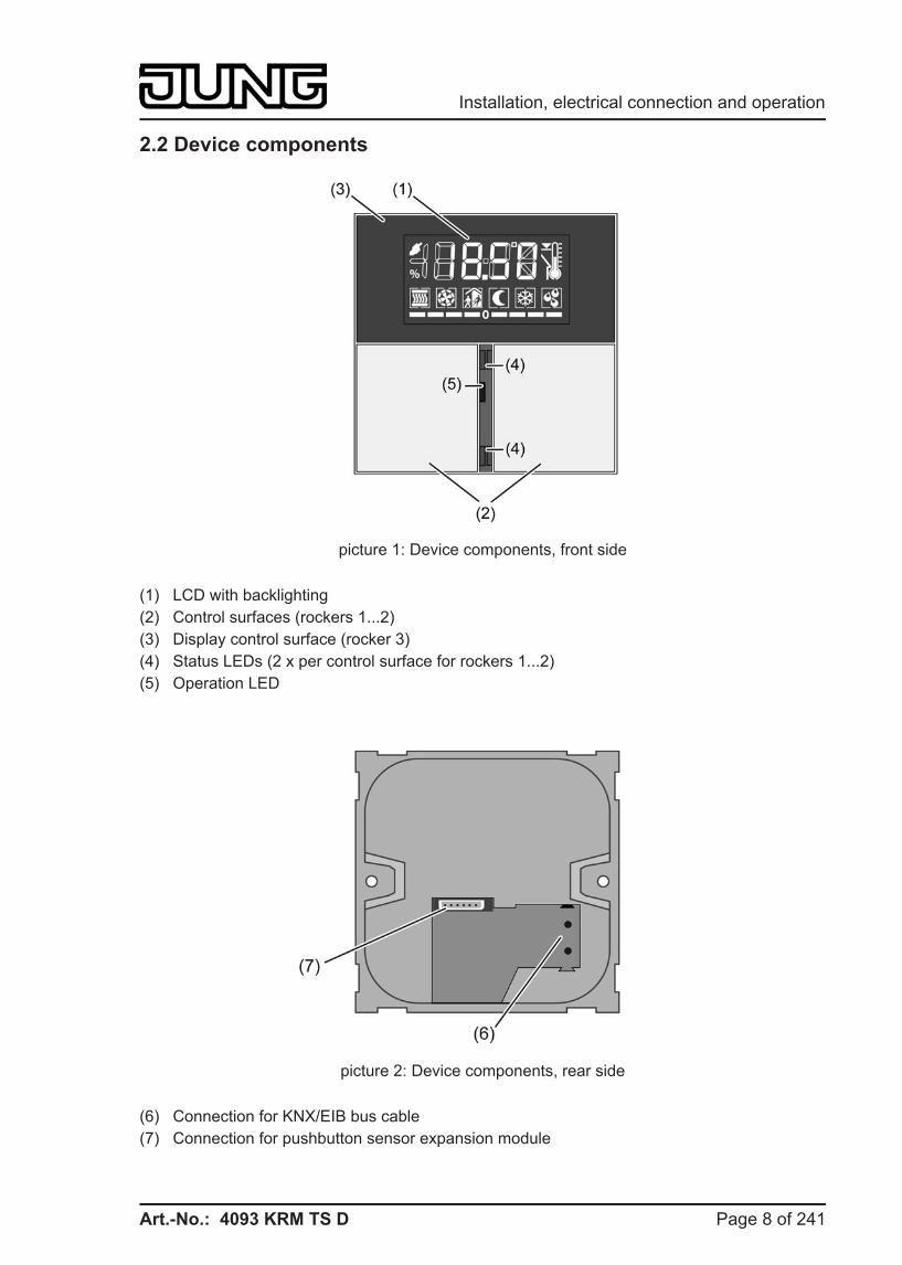
2.2 Device components
picture 1: Device components, front side
(1) LCD with backlighting (2) Control surfaces (rockers 1...2) (3) Display control surface (rocker 3) (4) Status LEDs (2 x per control surface for rockers 1...2) (5) Operation LED
picture 2: Device components, rear side
(6) Connection for KNX/EIB bus cable (7) Connection for pushbutton sensor expansion module
Page 8 of 241
Installation, electrical connection and operation
Art.-No.: 4093 KRM TS D
2.3 Fitting and electrical connection
DANGER! Electrical shock on contact with live parts in the installation environment. Electrical shocks can be fatal. Before working on the device, disconnect the power supply and cover up live parts in the working environment.
DANGER! When mounting with 230 V devices under a common cover, e.g. socket outlets, there is a danger of electrical shocks in the event of a fault! Electrical shocks can be fatal. Do not install any 230 V devices in combination with a pushbutton expansion module under a common cover!
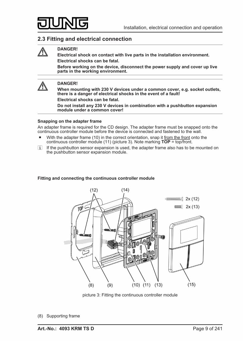
Snapping on the adapter frame An adapter frame is required for the CD design. The adapter frame must be snapped onto the continuous controller module before the device is connected and fastened to the wall. o With the adapter frame (10) in the correct orientation, snap it from the front onto the
continuous controller module (11) (picture 3). Note marking TOP = top/front. i If the pushbutton sensor expansion is used, the adapter frame also has to be mounted on
the pushbutton sensor expansion module.
Fitting and connecting the continuous controller module
picture 3: Fitting the continuous controller module
(8) Supporting frame
Page 9 of 241
Installation, electrical connection and operation
Art.-No.: 4093 KRM TS D
(9) Design frame (10) Adapter frame (11) Continuous controller module (12) Box screws (13) Fastening screws (14) KNX connection terminal (15) Design control surfaces
i Recommended installation height: 1.50 m. i The installation of the supporting frame depends on the design used.
Supporting frame side "A" to the front for switch design ranges A, CD and FD.Supporting frame side "B" to the front for switch design range LS.
o Mount supporting frame (8) in the right orientation on an appliance box. Note marking TOP; marking "A" or "B" in front. Use the enclosed box screws (12).
o Position the design frame (9) on the supporting frame. o Connect the continuous controller module (11) with KNX connection terminal (14), which is
connected to the KNX bus cable, on the rear side of the module. Run the connecting cable downwards from the continuous controller module and then into the appliance box from the rear.
o Push continuous controller module onto the supporting frame. o Fasten the continuous controller module to supporting frame using the enclosed plastic
screws (13). Tighten the plastic screws only lightly. o Before mounting the control surfaces (15), load the physical address into the device (see
chapter 2.4. Commissioning).
Page 10 of 241
Installation, electrical connection and operation
Art.-No.: 4093 KRM TS D
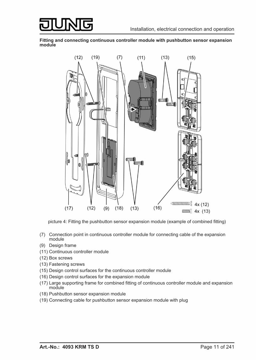
Fitting and connecting continuous controller module with pushbutton sensor expansion module
picture 4: Fitting the pushbutton sensor expansion module (example of combined fitting)
(7) Connection point in continuous controller module for connecting cable of the expansion module
(9) Design frame (11) Continuous controller module (12) Box screws (13) Fastening screws (15) Design control surfaces for the continuous controller module (16) Design control surfaces for the expansion module (17) Large supporting frame for combined fitting of continuous controller module and expansion
module (18) Pushbutton sensor expansion module (19) Connecting cable for pushbutton sensor expansion module with plug
Page 11 of 241
Installation, electrical connection and operation
Art.-No.: 4093 KRM TS D
i The installation of the supporting frame depends on the design used.Supporting frame side "A" to the front for switch design ranges A, CD and FD.Supporting frame side "B" to the front for switch design range LS.
One pushbutton sensor expansion module can be connected to each continuous controller module. For combined fitting of an expansion module directly underneath the continuous controller module, the large supporting frame (17) must be fitted (picture 4). The large supporting frame is contained in the scope of supply of the pushbutton sensor expansion module.For combined fitting on just a single appliance box, fit the continuous controller module with the KNX bus connection in the appliance box and countersink the fixing screws of the expansion module in the wall, for example using Ø 6 x 10 mm boreholes. The large supporting frame can be used as a template for this. i Recommended installation height for the continuous controller module: 1.50 m.
The expansion module can be installed in a separate box with the extension (see accessories) at a height of 1.10 m. The extension must be routed through a pipe. In this installation a separate small supporting frame is used for the expansion module (included in the scope of supply for the extension).
o For combined fitting underneath the continuous controller module: Fit large supporting frame (17) in the right orientation on an appliance box. Note marking TOP; marking "A" or "B" in front. Use the enclosed box screws (12).For individual fitting of the expansion module at 1.10 m: Fit small supporting frames for the continuous controller module and for the expansion module in the right orientation on two appliance boxes. Note marking TOP; marking "A" or "B" in front. Use the enclosed box screws (12).
o Position the design frame (9) on the supporting frame(s). o For combined fitting underneath the continuous controller module: Fit pushbutton sensor
expansion module (18) in the large supporting frame. Route connecting cable (19) between supporting frame and intermediate web.For individual fitting of the expansion module at 1.10 m: Fit pushbutton sensor expansion module (18) in separate small supporting frame. Guide connecting cable (19) through a pipe into the box of the continuous controller module.
o With the plug of the connecting cable in the right orientation, insert it into the connection point in the continuous controller module (7). When doing so, ensure that the connecting cable is not pinched.
o Connect the continuous controller module (11) with KNX connection terminal, which is connected to the KNX bus cable, on the rear side of the module. Run the connecting cable downwards from the continuous controller module and then into the appliance box from the rear.
o Push continuous controller module onto the supporting frame. o Fasten module to supporting frame using the enclosed plastic screws (13). Tighten the
plastic screws only lightly. o Mount the control surfaces on the pushbutton sensor expansion module (16). Before
mounting the control surfaces on the continuous controller module (15), load the physical address into the device (see chapter 2.4. Commissioning).
Page 12 of 241
Installation, electrical connection and operation
Art.-No.: 4093 KRM TS D
2.4 Commissioning After the device has been connected to the bus and mounted on the wall, it can be put into operation. Commissioning is basically confined to programming with the ETS and attaching the decorative control surfaces.
Assignment of the physical address
DANGER! Electrical shock when live parts are touched. Electrical shocks can be fatal. Before working on the device, disconnect the power supply and cover up live parts in the working environment.
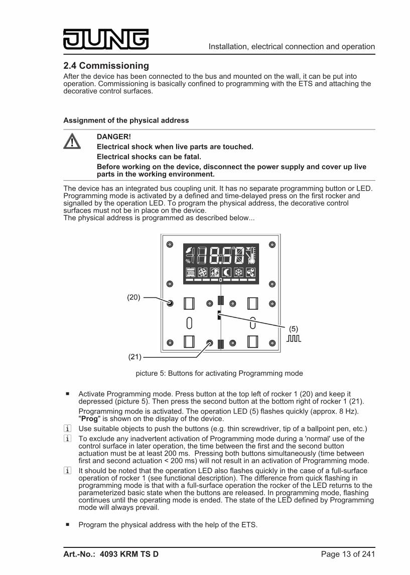
The device has an integrated bus coupling unit. It has no separate programming button or LED. Programming mode is activated by a defined and time-delayed press on the first rocker and signalled by the operation LED. To program the physical address, the decorative control surfaces must not be in place on the device.The physical address is programmed as described below...
picture 5: Buttons for activating Programming mode
o Activate Programming mode. Press button at the top left of rocker 1 (20) and keep it depressed (picture 5). Then press the second button at the bottom right of rocker 1 (21). Programming mode is activated. The operation LED (5) flashes quickly (approx. 8 Hz). "Prog" is shown on the display of the device.
i Use suitable objects to push the buttons (e.g. thin screwdriver, tip of a ballpoint pen, etc.) i To exclude any inadvertent activation of Programming mode during a 'normal' use of the
control surface in later operation, the time between the first and the second button actuation must be at least 200 ms. Pressing both buttons simultaneously (time between first and second actuation < 200 ms) will not result in an activation of Programming mode.
i It should be noted that the operation LED also flashes quickly in the case of a full-surface operation of rocker 1 (see functional description). The difference from quick flashing in programming mode is that with a full-surface operation the rocker of the LED returns to the parameterized basic state when the buttons are released. In programming mode, flashing continues until the operating mode is ended. The state of the LED defined by Programming mode will always prevail.
o Program the physical address with the help of the ETS.
Page 13 of 241
Installation, electrical connection and operation
Art.-No.: 4093 KRM TS D
The operation LED switches back to the previous status (off, on or flashing slowly). i If Programming mode is to be activated or deactivated in a device which is already
programmed with a valid application, there is the possibility that telegrams will be transmitted to the bus at the time the button is pressed. The telegram transmitted depends on the push-button function programmed.
i The expansion module does not receive any physical address of its own. It is activated by the application program loaded in the continuous controller module.
Programming the application The application must then be programmed into the device with the help of the ETS. The ETS3.0 from version "d" onwards detects automatically whether a valid application has already been programmed into the device before. To reduce the programming time, the ETS3 downloads the whole application only if the device was programmed beforehand with another application or with no application at all. In all other cases, the ETS makes a time-optimised partial download in which only the modified data is loaded into the device. For commissioning. it is recommended to use the ETS3.0 from Version d Patch A onwards. i The expansion module does not receive any physical address of its own. It is activated by
the application program loaded in the continuous controller module.
Installing the decorative control surfaces The decorative control surfaces are available as a complete set of buttons. Individual buttons or the complete set of buttons can be replaced using buttons with symbols.The design control surfaces are not included in the scope of supply of the continuous controller module or the pushbutton sensor expansion module. These must be ordered specially according to the required design. The physical address of the continuous controller module must be programmed in the device in advance. o Place control surfaces on the continuous controller module in the right orientation and also
on the pushbutton sensor expansion module (if used), and snap in with a short push. Note marking TOP.
i To simplify installation, a complete set of buttons is fitted with a mounting spider at the factory. This mounting spider is not essential for installing the decorative control surfaces, meaning that it is not required when adding symbol buttons to the button panel.
Page 14 of 241
Installation, electrical connection and operation
Art.-No.: 4093 KRM TS D
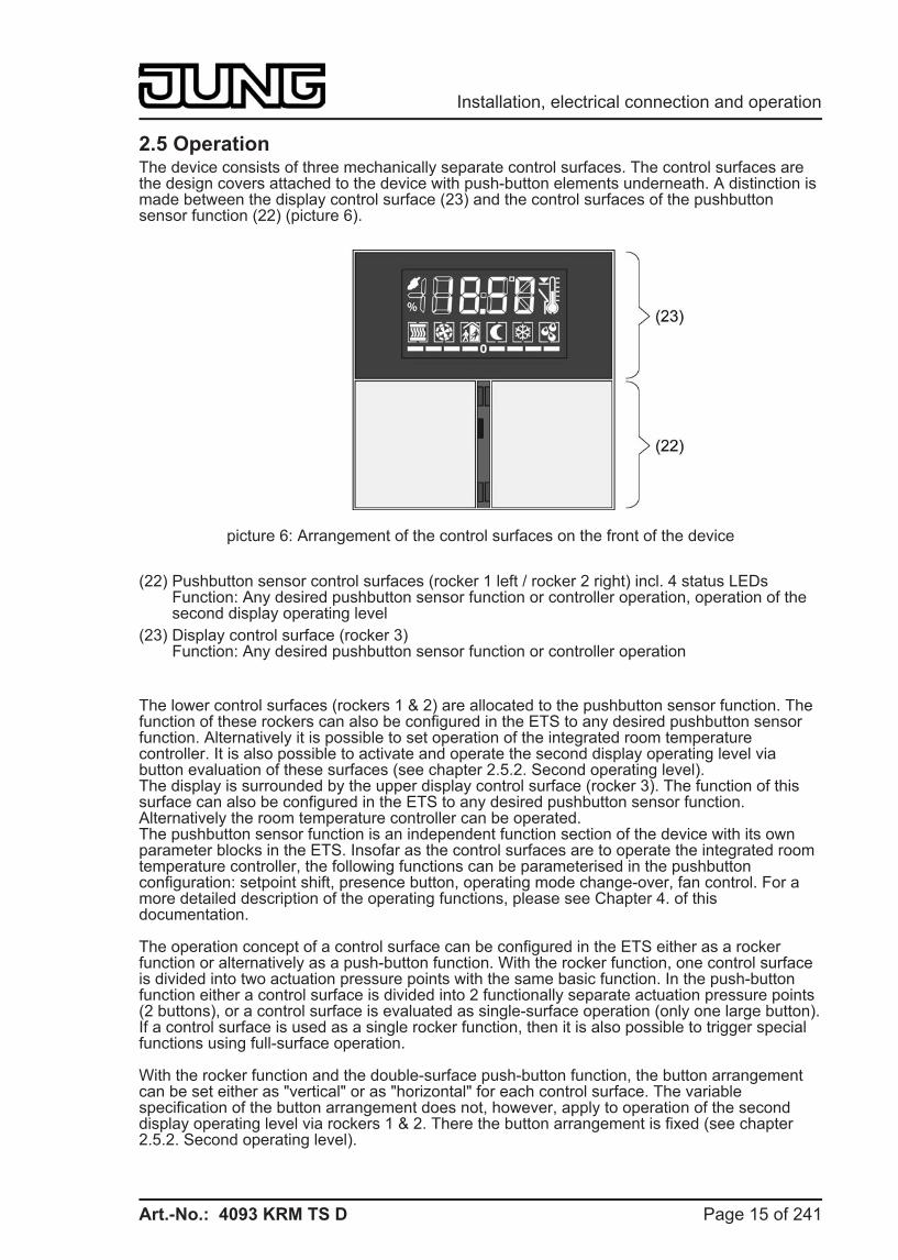
2.5 Operation The device consists of three mechanically separate control surfaces. The control surfaces are the design covers attached to the device with push-button elements underneath. A distinction is made between the display control surface (23) and the control surfaces of the pushbutton sensor function (22) (picture 6).
picture 6: Arrangement of the control surfaces on the front of the device
(22) Pushbutton sensor control surfaces (rocker 1 left / rocker 2 right) incl. 4 status LEDsFunction: Any desired pushbutton sensor function or controller operation, operation of the second display operating level
(23) Display control surface (rocker 3)Function: Any desired pushbutton sensor function or controller operation
The lower control surfaces (rockers 1 & 2) are allocated to the pushbutton sensor function. The function of these rockers can also be configured in the ETS to any desired pushbutton sensor function. Alternatively it is possible to set operation of the integrated room temperature controller. It is also possible to activate and operate the second display operating level via button evaluation of these surfaces (see chapter 2.5.2. Second operating level).The display is surrounded by the upper display control surface (rocker 3). The function of this surface can also be configured in the ETS to any desired pushbutton sensor function. Alternatively the room temperature controller can be operated.The pushbutton sensor function is an independent function section of the device with its own parameter blocks in the ETS. Insofar as the control surfaces are to operate the integrated room temperature controller, the following functions can be parameterised in the pushbutton configuration: setpoint shift, presence button, operating mode change-over, fan control. For a more detailed description of the operating functions, please see Chapter 4. of this documentation.
The operation concept of a control surface can be configured in the ETS either as a rocker function or alternatively as a push-button function. With the rocker function, one control surface is divided into two actuation pressure points with the same basic function. In the push-button function either a control surface is divided into 2 functionally separate actuation pressure points (2 buttons), or a control surface is evaluated as single-surface operation (only one large button).If a control surface is used as a single rocker function, then it is also possible to trigger special functions using full-surface operation.
With the rocker function and the double-surface push-button function, the button arrangement can be set either as "vertical" or as "horizontal" for each control surface. The variable specification of the button arrangement does not, however, apply to operation of the second display operating level via rockers 1 & 2. There the button arrangement is fixed (see chapter 2.5.2. Second operating level).
Page 15 of 241
Installation, electrical connection and operation
Art.-No.: 4093 KRM TS D
Optionally, the number of control surfaces can be expanded to include up to 4 additional ones by connecting an expansion module to the continuous controller module. Configuration and commissioning of the expansion module is clearly structured and easy to perform using the application program of the continuous controller module. The control surfaces of the expansion module can be set in the ETS to any desired pushbutton sensor function, or also to controller operation.
Between the lower control surfaces of the continuous controller module (rockers 1 & 2) there are 4 red status LEDs, 2 for each rocker. These status LEDs can be internally connected to the operating function according to the function of the rocker or pushbuttons, thus indicating the operating status directly. They may, however, also be used for signalling completely independent functions or be permanently on or off.The operation LED can also signal the switching state of its own object, flash or be permanently on or off. Besides functions that can be set using the ETS, the operation LED also indicates that the device is in the programming mode for commissioning or diagnosis purposes.
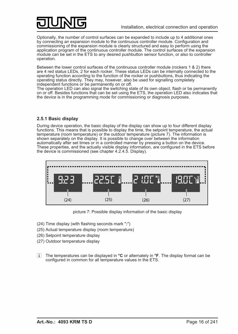
2.5.1 Basic display During device operation, the basic display of the display can show up to four different display functions. This means that is possible to display the time, the setpoint temperature, the actual temperature (room temperature) or the outdoor temperature (picture 7). The information is shown separately on the display. It is possible to change over between the information automatically after set times or in a controlled manner by pressing a button on the device. These properties, and the actually visible display information, are configured in the ETS before the device is commissioned (see chapter 4.2.4.5. Display).
picture 7: Possible display information of the basic display
(24) Time display (with flashing seconds mark ":") (25) Actual temperature display (room temperature) (26) Setpoint temperature display (27) Outdoor temperature display
i The temperatures can be displayed in °C or alternately in °F. The display format can be configured in common for all temperature values in the ETS.
Page 16 of 241
Installation, electrical connection and operation
Art.-No.: 4093 KRM TS D
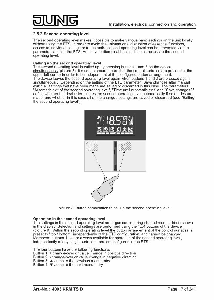
2.5.2 Second operating level The second operating level makes it possible to make various basic settings on the unit locally without using the ETS. In order to avoid the unintentional disruption of essential functions, access to individual settings or to the entire second operating level can be prevented via the parameterisation in the ETS. An active button disable also disables access to the second operating level.
Calling up the second operating levelThe second operating level is called up by pressing buttons 1 and 3 on the device simultaneously(picture 8). It must be ensured here that the control surfaces are pressed at the upper left corner in order to be independent of the configured button arrangement.The device leaves the second operating level again when buttons 1 and 3 are pressed again simultaneously. Depending on the setting of the ETS parameter "Save changes after manual exit?" all settings that have been made are saved or discarded in this case. The parameters "Automatic exit of the second operating level", "Time until automatic exit" and "Save changes?" define whether the device terminates the second operating level automatically if no entries are made, and whether in this case all of the changed settings are saved or discarded (see "Exiting the second operating level").
picture 8: Button combination to call up the second operating level
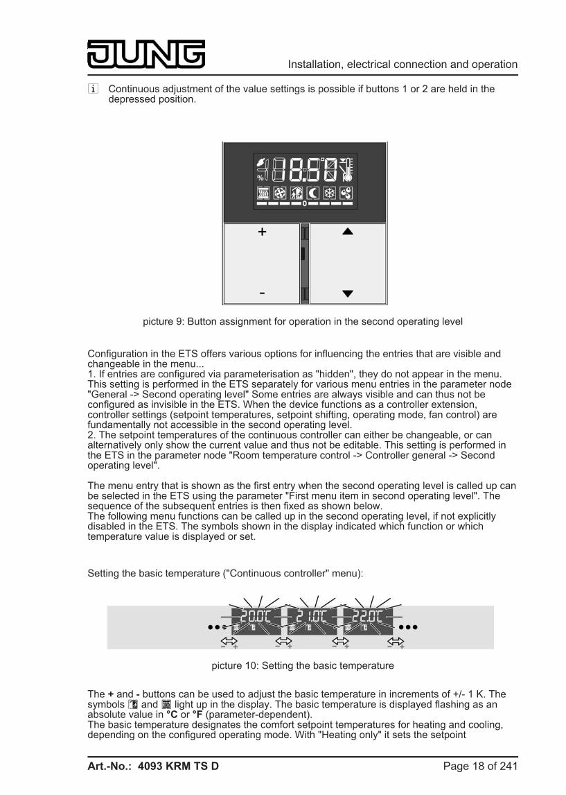
Operation in the second operating levelThe settings in the second operating level are organised in a ring-shaped menu. This is shown in the display. Selection and settings are performed using the 1...4 buttons of the device (picture 9). Within the second operating level the button arrangement of the control surfaces is preset to "top / bottom" independently of the ETS configuration, and cannot be changed. Moreover, buttons 1...4 are always available for operation of the second operating level, independently of any single-surface operation configured in the ETS.
The four buttons have the following functions...Button 1: + change-over or value change in positive directionButton 2: - change-over or value change in negative directionButton 3: n Jump to the previous menu entryButton 4: o Jump to the next menu entry
Page 17 of 241
Installation, electrical connection and operation
Art.-No.: 4093 KRM TS D
i Continuous adjustment of the value settings is possible if buttons 1 or 2 are held in the depressed position.
picture 9: Button assignment for operation in the second operating level
Configuration in the ETS offers various options for influencing the entries that are visible and changeable in the menu...1. If entries are configured via parameterisation as "hidden", they do not appear in the menu. This setting is performed in the ETS separately for various menu entries in the parameter node "General -> Second operating level" Some entries are always visible and can thus not be configured as invisible in the ETS. When the device functions as a controller extension, controller settings (setpoint temperatures, setpoint shifting, operating mode, fan control) are fundamentally not accessible in the second operating level.2. The setpoint temperatures of the continuous controller can either be changeable, or can alternatively only show the current value and thus not be editable. This setting is performed in the ETS in the parameter node "Room temperature control -> Controller general -> Second operating level".
The menu entry that is shown as the first entry when the second operating level is called up can be selected in the ETS using the parameter "First menu item in second operating level". The sequence of the subsequent entries is then fixed as shown below.The following menu functions can be called up in the second operating level, if not explicitly disabled in the ETS. The symbols shown in the display indicated which function or which temperature value is displayed or set.
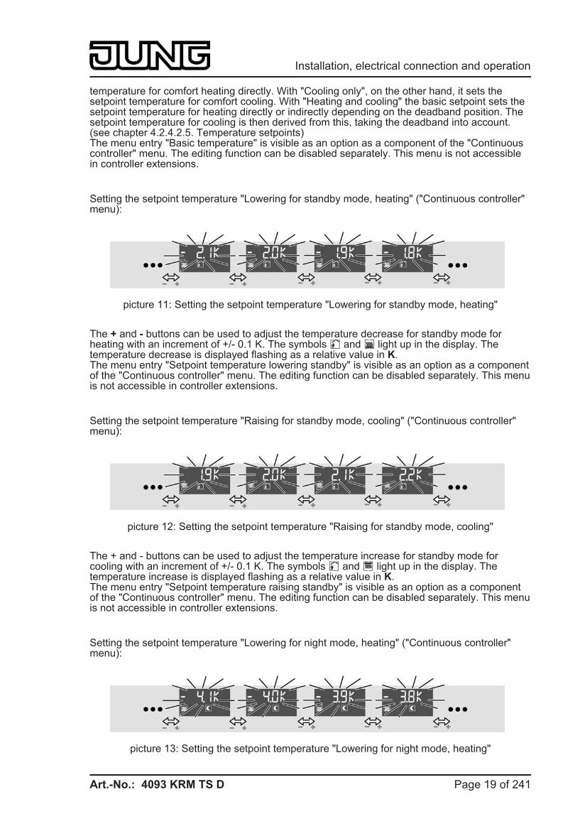
Setting the basic temperature ("Continuous controller" menu):
picture 10: Setting the basic temperature
The + and - buttons can be used to adjust the basic temperature in increments of +/- 1 K. The symbols ó and ÿ light up in the display. The basic temperature is displayed flashing as an absolute value in °C or °F (parameter-dependent).The basic temperature designates the comfort setpoint temperatures for heating and cooling, depending on the configured operating mode. With "Heating only" it sets the setpoint
Page 18 of 241
Installation, electrical connection and operation
Art.-No.: 4093 KRM TS D
temperature for comfort heating directly. With "Cooling only", on the other hand, it sets the setpoint temperature for comfort cooling. With "Heating and cooling" the basic setpoint sets the setpoint temperature for heating directly or indirectly depending on the deadband position. The setpoint temperature for cooling is then derived from this, taking the deadband into account. (see chapter 4.2.4.2.5. Temperature setpoints)The menu entry "Basic temperature" is visible as an option as a component of the "Continuous controller" menu. The editing function can be disabled separately. This menu is not accessible in controller extensions.
Setting the setpoint temperature "Lowering for standby mode, heating" ("Continuous controller" menu):
picture 11: Setting the setpoint temperature "Lowering for standby mode, heating"
The + and - buttons can be used to adjust the temperature decrease for standby mode for heating with an increment of +/- 0.1 K. The symbols ô and â light up in the display. The temperature decrease is displayed flashing as a relative value in K.The menu entry "Setpoint temperature lowering standby" is visible as an option as a component of the "Continuous controller" menu. The editing function can be disabled separately. This menu is not accessible in controller extensions.
Setting the setpoint temperature "Raising for standby mode, cooling" ("Continuous controller" menu):
picture 12: Setting the setpoint temperature "Raising for standby mode, cooling"
The + and - buttons can be used to adjust the temperature increase for standby mode for cooling with an increment of +/- 0.1 K. The symbols ô and è light up in the display. The temperature increase is displayed flashing as a relative value in K.The menu entry "Setpoint temperature raising standby" is visible as an option as a component of the "Continuous controller" menu. The editing function can be disabled separately. This menu is not accessible in controller extensions.
Setting the setpoint temperature "Lowering for night mode, heating" ("Continuous controller" menu):
picture 13: Setting the setpoint temperature "Lowering for night mode, heating"
Page 19 of 241
Installation, electrical connection and operation
Art.-No.: 4093 KRM TS D
The + and - buttons can be used to adjust the temperature decrease for night mode for heating with an increment of +/- 0.1 K. The symbols õ and â light up in the display. The temperature decrease is displayed flashing as a relative value in K.The menu entry "Setpoint temperature lowering night" is visible as an option as a component of the "Continuous controller" menu. The editing function can be disabled separately. This menu is not accessible in controller extensions.
Setting the setpoint temperature "Raising for night mode, cooling" ("Continuous controller" menu):
picture 14: Setting the setpoint temperature "Raising for night mode, cooling"
The + and - buttons can be used to adjust the temperature increase for night mode for cooling with an increment of +/- 0.1 K. The symbols õ and è are illuminated in the display. The temperature increase is displayed flashing as a relative value in K.The menu entry "Setpoint temperature raising night" is visible as an option as a component of the "Continuous controller" menu. The editing function can be disabled separately. This menu is not accessible in controller extensions.
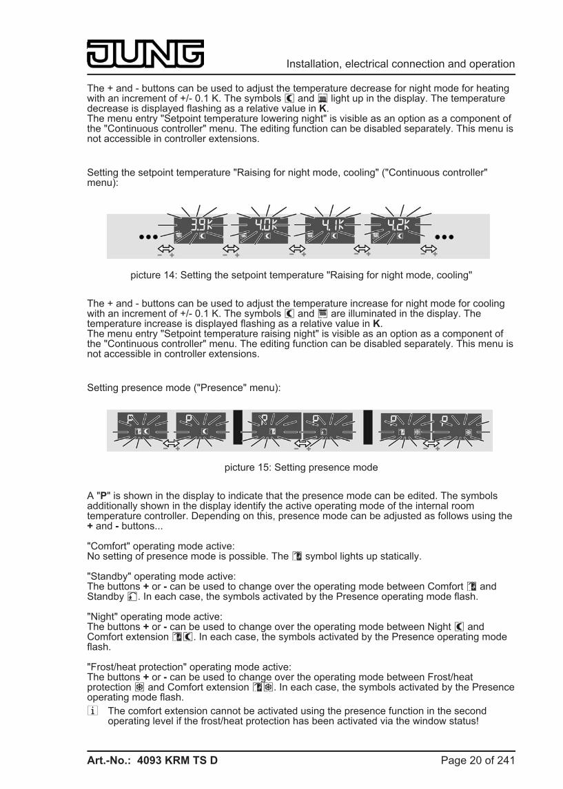
Setting presence mode ("Presence" menu):
picture 15: Setting presence mode
A "P" is shown in the display to indicate that the presence mode can be edited. The symbols additionally shown in the display identify the active operating mode of the internal room temperature controller. Depending on this, presence mode can be adjusted as follows using the + and - buttons...
"Comfort" operating mode active:No setting of presence mode is possible. The ó symbol lights up statically.
"Standby" operating mode active:The buttons + or - can be used to change over the operating mode between Comfort ó and Standby ô. In each case, the symbols activated by the Presence operating mode flash.
"Night" operating mode active:The buttons + or - can be used to change over the operating mode between Night õ and Comfort extension óõ. In each case, the symbols activated by the Presence operating mode flash.
"Frost/heat protection" operating mode active:The buttons + or - can be used to change over the operating mode between Frost/heat protection ö and Comfort extension óö. In each case, the symbols activated by the Presence operating mode flash. i The comfort extension cannot be activated using the presence function in the second
operating level if the frost/heat protection has been activated via the window status!
Page 20 of 241
Installation, electrical connection and operation
Art.-No.: 4093 KRM TS D
i In the second operating level, presence mode and operating mode (see "Setting the operating mode" below) may never be changed at the same time before a "save" command. Otherwise the presence status is always reset, and thus the manual setting may not be applied. If the controller operating mode and the presence mode have to be changed, first the operating mode has to be changed and the setting has to be saved. Only after that is it possible to change the presence mode and save this setting by calling up the second operating level again.
The menu entry "Presence" is visible as an option. This menu is not accessible in controller extensions.
Setting the setpoint shift ("Setpoint shift" menu):
picture 16: Setting the setpoint shift
The menu entry for setpoint shifting is indicated in the display by the bar scale "- - - - 0 - - - -". The buttons + and - can be used to adjust the basic setpoint shift by up to 4 levels. Here the shift is shown in the display as a relative numeric value in kelvin (K)The increment of the shift depends on the ETS parameter "Increment of the 4-level setpoint shift" in the parameter branch "Room temperature controller -> Controller general -> Setpoints". i A setpoint shift cannot be saved when the second operating level is exited if the frost/heat
protection is activated in the controller! In this case the settings of the setpoint shift in the second operating level are lost.
The menu entry "Setpoint shift" is visible as an option. This menu is not accessible in controller extensions.
Setting the operating mode ("Operating mode" menu):
picture 17: Setting the operating mode
The buttons + and - can be used to adjust the controller operating mode. The symbol for the active operating mode flashes in the display. The modes that can be set are "Comfort" ó, "Standby" ô, "Night" õ and "Frost/heat protection" ö.It should be noted that a set operating mode with a low priority cannot be activated immediately when the second operating level is exited if an operating mode with a higher priority (e.g. frost protection via window status) has been specified by the controller (see chapter 4.2.4.2.4. Operating mode change-over). The operating mode set in the second operating level is only accepted by the controller when the operating mode with a higher priority has been terminated and in the meantime no other operating mode specification with a higher priority has been performed (e.g. via operation of a pushbutton sensor or via communication objects).The menu entry "Operating mode" is visible as an option. This menu is not accessible in controller extensions.
Page 21 of 241
Installation, electrical connection and operation
Art.-No.: 4093 KRM TS D
Fan control ("Fan levels" menu):
picture 18: Fan controller
The + and - buttons can be used to influence the fan operating mode (automatic / manual mode). In manual mode it is possible to change over the fan level independently of the controller command values (see chapter 4.2.4.2.8. Fan controller).When the menu entry "Fan levels" is called up, the fan symbol in the display flashes, and indicates the current fan level by means of the illuminated arc segments ( ì, í, î etc.). If no arc segment is illuminated, the fan is switched off. The display also shows whether the fan controller is in automatic or manual operation. In manual operation the Ü symbol is also illuminated. The number of illuminated arc segments depends on the number of fan levels configured. i In fan control in the second operating level the fan level and automatic mode can be set
directly without taking into account the specific settings of the fan controller (Parameter "Fan level on change-over to manual", the switch-on level or fan run-on times).
The menu item "Fan levels" is visible as an option, but only if the fan control is also enabled in the controller for the ETS. This menu is not accessible in controller extensions.
Indicating the time:
picture 19: Indicating the time
Only indication of the current time. No adjustment possibility.The menu entry "Time" is visible as an option.
Indication of actual temperature:
picture 20: Indication of actual temperature
Only Indication of the current room temperature No adjustment possibility.The menu entry "Actual temperature" is visible as an option.
Indication of setpoint temperature:
Page 22 of 241
Installation, electrical connection and operation
Art.-No.: 4093 KRM TS D
picture 21: Indication of setpoint temperature
Only indication of the current setpoint temperature. No adjustment possibility.The menu entry "Setpoint temperature" is visible as an option.
Indicating the outdoor temperature:
picture 22: Indicating the outdoor temperature
Only indication of the current outdoor temperature No adjustment possibility.The menu entry "Outdoor temperature" is visible as an option.
Setting the display contrast:
picture 23: Setting the display contrast
Illuminate all elements of the display. The buttons + and - can be used to adjust the display contrast.The menu item "Display contrast" is always visible.
Setting the display brightness:
picture 24: Setting the display brightness
"H" and the brightness value of the backlighting are displayed in the backlighting. The buttons + and - can be used to adjust the brightness of the display in the range from 10 to 100%. For additional notes about control of the backlighting, via the second operating level, please see the chapter "Display control" (see page 165-166).The menu item "Display brightness" is always visible.
Exiting the second operating level by pressing Save:
Page 23 of 241
Installation, electrical connection and operation
Art.-No.: 4093 KRM TS D
picture 25: Exiting the second operating level by pressing Save:
"OK" is displayed. The buttons + or - can be used to exit the second operating level with a "save" command (see "Exiting the second operating level").This option is always visible.
Exiting the second operating level without saving:
picture 26: Exiting the second operating level without saving
"ESC" is shown on the display. The buttons + or - can be used to exit the second operating level without saving the settings (see "Exiting the second operating level").This option is always visible.
i All menu entries are displayed or not depending on the configuration of the ETS. If, for example, the controller is parameterised only for heating, no setpoints for cooling can be displayed or set in the menu. When the device functions as a controller extension, controller settings (setpoint temperatures, setpoint shifting, operating mode, fan control) are fundamentally not accessible in the second operating level.If an entry has been parameterised as the first menu item in the ETS that is not accessible at all due to the other settings, the first possible entry is displayed according to the defined menu sequence (see above).
i When a menu entry is shown on the display, the setting currently valid in the controller is identified using the symbols or the display value, if the setting has not already been changed previously in the second operating level. If the setting has already been changed and not yet accepted validly (see "Exiting the second operating level"), the last manual setting will be shown on the display, and not the real state of the controller.
Exiting the second operating level Settings that have been made in the second operating level are only accepted validly in the device when the operating level is exited with a "Save" command. It is possible to discard settings by exiting the second operating level without a "Save" process. When exiting the second operating level, a distinction is made among the following cases...
- Exiting by means of button combination: The second operating level is exited by pressing buttons 1 and 3 on the device simultaneously (picture 8). Here the parameter "Save changes after exiting with button combination?" defines whether the settings are saved or not when the second operating level is exited using the button combination.
Page 24 of 241
Installation, electrical connection and operation
Art.-No.: 4093 KRM TS D
- Automatic exiting: Automatic exiting of the second operating level can optionally be configured in the ETS using the parameter of the same name in the parameter branch "General -> Second operating level". In this case the device leaves the second operating level when no additional operation takes place after the last push-button operation within the "Time until automatic exit" configured in the ETS. With automatic exiting it is also possible to define with the parameter "Save changes after automatic exiting?" whether the settings are saved or not.
- Exiting with "OK": In the second operating level the menu item "OK" can be selected with the n or o buttons. The buttons + or - can then be used to exit the second operating level. All settings are always saved in this case!
- Exiting with "ESC": In the second operating level the menu item "ESC" can be selected with the n or o buttons. The buttons + or - can then be used to exit the second operating level. In this case the settings are not saved and are discarded!
Page 25 of 241
Installation, electrical connection and operation
Art.-No.: 4093 KRM TS D
3 Technical data General Safety class III Mark of approval KNX Ambient temperature -5 ... +45 °C Storage/transport temperature -25 ... +70 °C
KNX/EIB supply KNX medium TP 1 Commissioning mode S mode Rated voltage KNX DC 21 V ... 32 V SELV Power consumption KNX typical 150 mW Connection mode KNX Connection terminal
Page 26 of 241
Technical data
Art.-No.: 4093 KRM TS D
4 Software description
4.1 Software specification ETS search paths: - Heating, A/C, Ventilation / Valve / Room controller display
compact module- Push-button / Push-button, general / Room controller display compact module
BAU used: FZE 1066 + µC KNX/EIB type class: 3b device with cert. Physical layer + stack Configuration: S mode standard PEI type: "00"Hex / "0" Dec PEI connector: No connector
Application program:
No. Short description Name Version from mask version
1 Multifunctional room temperature controller / pushbutton sensor application:Up to 3 control surfaces on the continuous controller module for the pushbutton sensor function and for operation of the integrated room temperature controller. Can be expanded to include 4 additional control surfaces using an expansion module.
Continuous controller module 3gang 146A11
1.1for ETS3.0donwards
705
Page 27 of 241
Software specification
Art.-No.: 4093 KRM TS D
4.2 Software "Continuous controller module 3gang 146A11" 4.2.1 Scope of functions
General functions - The operation LED can be permanently on or off or alternatively be switched via a
communication object. - Internal clock to indicate the time on the device display. The time information is made
available to the device using a communication object (e.g. by a KNX/EIB timer switch). Automatic time request possible after a device restart.
- LC display with switchable backlighting. On the display, icons signal various operating states of the integrated room temperature controller or the controller extension. In addition, up to four display functions (time, actual temperature, setpoint temperature, outdoor temperature) can be shown on the display either alternating over time or controlled by pressing a button.
- Integrated scene control. Internal storage of up to eight scenes with eight output channels, recall of internal scenes by means of a presettable scene number, selection of object types for the output channels; for each scene, the storage of the individual output values and the transmission of the output values can be permitted or inhibited; the individual channels can be delayed during scene recall; as scene extension, 64 scenes can be recalled and stored.
- The number of control surfaces can be expanded using a pushbutton sensor expansion module.
Functions of the integrated pushbutton sensor - Each control surface can either be used as a single rocker or as two independent buttons. - For push-button function either double-surface or single-surface principle. - Each rocker can be used for the functions 'switching', 'dimming', 'Venetian blind', '1 byte
value transmitter', '2-byte value transmitter', 'scene extension' and '2-channel operation'. - Each button can be used for the functions 'switching', 'dimming', 'Venetian blind', '1 byte
value transmitter', '2-byte value transmitter', 'scene extension' and '2-channel operation', 'controller extension', 'fan controller', 'controller operating mode', 'setpoint shift', and 'change in the display reading'. The 'fan controller', 'controller operating mode' and 'setpoint shift' functions are used to operate the integrated room temperature controller.
- 2-channel operating function: each rocker or each button can be set for controlling two independent channels. This means that only one button-press is enough to transmit up to two telegrams to the bus. The channels can be configured independently of one another for the functions Switching, Value transmitter (1 byte) or Temperature value transmitter (2 bytes).
- For the rocker functions Dimming, Venetian blind (operation concept "Long – Short or Short")' and 2-channel operation, full-surface rocker actuation can also be evaluated. With full-surface rocker operation, switching telegrams and scene recall requests can be triggered on the bus in addition to and independently of the configured rocker function.
- The switching function permits the following settings: reaction after pressing and/or releasing, switch on, switch off, and toggle.
- The dimming function permits the following settings: times for short and long actuation, dimming in different levels, telegram repetition on long press, transmission of stop telegram after end of press.
- The shutter control permits the following settings: four different operation concepts with times for short and long press and slat adjustment.
- The 1-byte and 2-byte value transmitter function permits the following settings: selection of the value range (0 … 100 %, 0 … 255, 0 … 65535, 0 … 1500 lux, 0 … 40 °C), value on button-press, value change on sustained button-press with different level sizes, optional overflow on reaching the end of a value range.
- The controller extension function permits the following settings to operate an external room temperature controller: operating mode change-over with normal and high priority, defined selection of an operating mode, change between different operating modes, change of presence status, setpoint shift.
Page 28 of 241
Software "Continuous controller module 3gang 146A11" Scope of functions
Art.-No.: 4093 KRM TS D
- Each control surface has two status LEDs (exception: display control surface). When a status LED is internally connected with the rocker or the button, it can signal a button-press or the current status of a communication object. The status indication can also be in inverted form. When a status LED is not dependent on the rocker or button, it can be permanently on or off, indicate the status of an independent communication object, the operating state of a room temperature controller or the result of a comparison between signed or unsigned 1 byte values.
- The rockers or buttons can be disabled via a 1-bit object. The following settings are possible: polarity of the disabling object, behaviour at the beginning and at the end of disabling. During an active disable, all or some of the rockers / buttons can have no function, can perform the function of a selected button or execute one of two presettable disabling functions.
- A delay to the automatically transmitted communication objects of the controller external after a device reset can be configured. The delay time is automatically produced by the subscriber address (physical address).
- All LEDs of the pushbutton sensor can flash simultaneously in the event of an alarm message. The following settings are possible: Value of alarm message object for the states alarm / no alarm, alarm acknowledge by pressing a button, transmission of the acknowledge signal to other devices.
Functions of the integrated room temperature controller - Various operating modes can be activated: Comfort, Standby, Night and Frost/heat
protection - Each operating mode can be assigned its own temperature setpoints (for heating and/or
cooling). - Comfort extension possible using presence button in Night or Frost/heat protection mode.
Configurable duration of the comfort extension. - Operating mode change-over via 1-byte object according to KONNEX or using up to four
individual 1-bit objects. - Frost/heat protection change-over via window status. - Indication of room temperature controller information via the device display - Function buttons to operate the controller (setpoint shift and second operating level, for
example to change the setpoint temperatures). - Operating modes "Heating", "Cooling", "Heating and cooling" each with or without
additional level. - Various control types can be configured for each heating or cooling level: PI feedback
control (permanent or switching PWM) or 2-point feedback control (switching). - Control parameter for PI controller (if desired: proportional range, reset time) and 2-point
controller (hysteresis) adjustable. - The temperature setpoints for the additional level are derived via a configurable level offset
from the values of the basic level. - Automatic or object oriented change-over between "Heating" and "Cooling". - Temporary setpoint shifting or permanent setpoint shifting through operation of the function
buttons on the device or via communication objects possible (e.g. using a controller extension). Indication of the setpoint shift on the device display by means of a line graphic.
- Complete (1-byte) or partial (1-bit) status information configurable and transmissible on the bus via objects.
- Deactivating the feedback control or the additional level possible using separate 1-bit objects.
- Internal and external temperature sensor for room temperature measurement possible. - Configurable internal to external determination of measured value and enabled external
sensor for room temperature measurement. Settable polling time of the external temperature sensor.
- The room temperature measurement (actual value) can be adjusted separately for the internal and external sensor using parameters.
- The actual and setpoint temperatures can be output on the bus if a configurable deviation is detected (also periodically).
- Separate or shared command value output in heating and cooling mode. This produces one or two command value objects for each level.
- Normal or inverted command value output configurable - Automatic transmission and cycle time for command value output configurable
Page 29 of 241
Software "Continuous controller module 3gang 146A11" Scope of functions
Art.-No.: 4093 KRM TS D
- Floor temperature limit possible in heating mode. Thus temperature-controlled switch-off of a floor heater as protective function.
- Setpoint temperature limit possible in cooling mode. If necessary, the controller limits the setpoint temperature to specific values and prevents an adjustment beyond statutory limits.
Functions of the integrated controller extension - Alternatively to the function of the room temperature controller, the extension mode can be
activated. This allows control of an external room temperature controller. - Full control of the controller (operating modes, presence functions and setpoint shift). - Full-featured indication of the controller status on the display of the extension (heating /
cooling reporting, setpoint shift, room temperature, setpoint temperature and current operating mode).
- Room temperature measurement also possible on the extension.
Page 30 of 241
Software "Continuous controller module 3gang 146A11" Scope of functions
Art.-No.: 4093 KRM TS D
4.2.2 Notes on software
ETS configuration and commissioning For configuration and commissioning of the device, at least ETS3.0 from Version d Patch A onwards is required. Advantages with regard to downloading (significantly shorter loading times) and parameter programming using the integrated database plug-in can be expected only if this ETS version or later versions are used.The necessary product database is offered in the *.VD4 format. No product database is available for ETS2 and older versions of ETS3.
Page 31 of 241
Software "Continuous controller module 3gang 146A11" Notes on software
Art.-No.: 4093 KRM TS D
4.2.3 Object table
Number of communication objects: 112 Number of addresses (max): 254 Number of assignments (max): 255 Dynamic table management Yes Maximum table length 509
4.2.3.1 Object table, pushbutton sensor function section
Objects for rocker or push-button function (basic or module control surfaces)
Function: Switching Object
h0
Function Switching
Name T.rocker/T.button 1 1,2
Type 1-bit
DPT 1.xxx
Flag C, W, T, (R) 3
Description 1-bit object for the transmission of switching telegrams (ON, OFF).
Function: Dimming Object
h0
Function Switching
Name T.rocker/T.button 1 1,2
Type 1-bit
DPT 1.xxx
Flag C, W, T, (R) 3
Description 1-bit object for the transmission of switching telegrams (ON, OFF).
Function: Dimming Object
h18
Function Dimming
Name T.rocker/T.button 1 1,2
Type 4-bit
DPT 3.007
Flag C, W, T, (R) 3
Description 4-bit object for the transmission of relative dimming telegrams.
1: The number of rockers or buttons depends on the planned pushbutton sensor variant and the pushbutton sensor expansion module. Mixed operation of rocker or push-button functions in a pushbutton sensor is possible on the basic module and the expansion module. 2: The objects have been described for rocker 1 or button 1 as an example. The objects for the rockers/buttons of the basic device and the module rockers/buttons are defined in the same way by shifting the object number and changing the object name. 3: For reading, the R-flag must be set. The last value written to the object via the bus or by the device will be read.
Page 32 of 241
Software "Continuous controller module 3gang 146A11" Object table
Art.-No.: 4093 KRM TS D
Function: Venetian blind Object
h0
Function Short-time operation
Name T.rocker/T.button 1 1,2
Type 1-bit
DPT 1.007
Flag C, -, T, (R) 3
Description 1-bit object for the transmission of telegrams with which a Venetian blind or shutter drive motor can be stopped or with which the blind slats can be adjusted by short-time operation.
Function: Venetian blind Object
h18
Function Long-time operation
Name T.rocker/T.button 1 1,2
Type 1-bit
DPT 1.008
Flag C, W, T, (R) 3
Description 1-bit object for the transmission of telegrams with which a Venetian blind or shutter drive motor can be can be moved upwards or downwards.
Function: 1-byte value transmitter Object
h0
Function Value
Name T.rocker/T.button 1 1,2
Type 1-byte
DPT 5.xxx
Flag C, W, T, (R) 3
Description 1-byte object for the transmission of values from 0 to 255 (corresponding to values from 0 % to 100 %). If the adjustment of the value is enabled, the object can transmit telegrams cyclically after a long press with which the value can be reduced or increased by a presettable amount.
Function: 2-byte value transmitter Object
h0
Function Value
Name T.rocker/T.button 1 1,2
Type 2-byte
DPT 7.xxx
Flag C, W, T, (R) 3
Description 2-byte object for the transmission of values from 0 to 65535. If the adjustment of the value is enabled, the object can transmit cyclical telegrams after a long press with which the value can be reduced or increased by an adjustable amount.
1: The number of rockers or buttons depends on the planned pushbutton sensor variant and the pushbutton sensor expansion module. Mixed operation of rocker or push-button functions in a pushbutton sensor is possible on the basic module and the expansion module. 2: The objects have been described for rocker 1 or button 1 as an example. The objects for the rockers/buttons of the basic device and the module rockers/buttons are defined in the same way by shifting the object number and changing the object name. 3: For reading, the R-flag must be set. The last value written to the object via the bus or by the device will be read.
Page 33 of 241
Software "Continuous controller module 3gang 146A11" Object table
Art.-No.: 4093 KRM TS D
Function: 2-byte value transmitter Object
h0
Function Temperature value
Name T.rocker/T.button 1 1,2
Type 2-byte
DPT 9.001
Flag C, W, T, (R) 3
Description 2 -byte object for the transmission of a temperature value from 0 °C to 40 °C. If the adjustment of the value is enabled, the object can transmit telegrams cyclically after a long press with which the value can be reduced or increased by 1 K.
Function: 2-byte value transmitter Object
h0
Function Brightness value
Name T.rocker/T.button 1 1,2
Type 2-byte
DPT 9.004
Flag C, W, T, (R) 3
Description 2-byte object for the transmission of a brightness level value from 0 to 1500 lux. If the adjustment of the value is enabled, the object can transmit cyclical telegrams after a long press with which the value can be reduced or increased by 50 lux.
Function: Scene extension Object
h0
Function Scene extension
Name T.rocker/T.button 1 1,2
Type 1-byte
DPT 18.001
Flag C, -, T, (R) 3
Description 1-byte object for recalling or for storing one of 64 scenes max. from a scene pushbutton sensor.
Function: 2-channel operation Object
h0
Function Channel 1 switching
Name T.rocker/T.button 1 1,2
Type 1-bit
DPT 1.xxx
Flag C, W, T, (R) 3
Description 1-bit object for the transmission of switching telegrams, if 2-channel operation is activated.
Function: 2-channel operation Object
h0
Function Channel 1 value
Name T.rocker/T.button 1 1,2
Type 1-byte
DPT 5.xxx
Flag C, -, T, (R) 3
Description 1-byte object for the transmission of value telegrams, if 2-channel operation is activated.
1: The number of rockers or buttons depends on the planned pushbutton sensor variant and the pushbutton sensor expansion module. Mixed operation of rocker or push-button functions in a pushbutton sensor is possible on the basic module and the expansion module. 2: The objects have been described for rocker 1 or button 1 as an example. The objects for the rockers/buttons of the basic device and the module rockers/buttons are defined in the same way by shifting the object number and changing the object name. 3: For reading, the R-flag must be set. The last value written to the object via the bus or by the device will be read.
Page 34 of 241
Software "Continuous controller module 3gang 146A11" Object table
Art.-No.: 4093 KRM TS D
Function: 2-channel operation Object
h0
Function Channel 1 value
Name T.rocker/T.button 1 1,2
Type 2-byte
DPT 9.001
Flag C, -, T, (R) 3
Description 2-byte object for the transmission of value telegrams, if 2-channel operation is activated.
Function: 2-channel operation Object
h18
Function Channel 2 switching
Name T.rocker/T.button 1 1,2
Type 1-bit
DPT 1.xxx
Flag C, W, T, (R) 3
Description 1-bit object for the transmission of switching telegrams, if 2-channel operation is activated.
Function: 2-channel operation Object
h18
Function Channel 2 value
Name T.rocker/T.button 1 1,2
Type 1-byte
DPT 5.xxx
Flag C, -, T, (R) 3
Description 1-byte object for the transmission of value telegrams, if 2-channel operation is activated.
Function: 2-channel operation Object
h18
Function Channel 2 value
Name T.rocker/T.button 1 1,2
Type 2-byte
DPT 9.001
Flag C, -, T, (R) 3
Description 2-byte object for the transmission of value telegrams, if 2-channel operation is activated.
1: The number of rockers or buttons depends on the planned pushbutton sensor variant and the pushbutton sensor expansion module. Mixed operation of rocker or push-button functions in a pushbutton sensor is possible on the basic module and the expansion module. 2: The objects have been described for rocker 1 or button 1 as an example. The objects for the rockers/buttons of the basic device and the module rockers/buttons are defined in the same way by shifting the object number and changing the object name. 3: For reading, the R-flag must be set. The last value written to the object via the bus or by the device will be read.
Page 35 of 241
Software "Continuous controller module 3gang 146A11" Object table
Art.-No.: 4093 KRM TS D
Objects for full-surface operation with rocker function (for dimming, Venetian blind and 2-channel operation)
Function: Full-surface operation Object
h1
Function Switching
Name T.rocker 1 full-surface actuation 1,2
Type 1-bit
DPT 1.xxx
Flag C, W, T, (R) 3
Description 1-bit object for the transmission of switching telegrams (ON, OFF) for full-surface operation of a sensor area.
Function: Full-surface operation Object
h1
Function Scene extension
Name T.rocker 1 full-surface actuation 1,2
Type 1-byte
DPT 18.001
Flag C, -, T, (R) 3
Description 1-byte object for recalling or for storing one of 64 scenes max. from a scene pushbutton sensor for full-surface operation of a sensor area.
Objects for status LED
Function: Status LED in case of rocker function Object
h36
Function Status LED top
Name T.rocker 14,2
Type 1-bit
DPT 1.xxx
Flag C, W, -, (R) 5
Description 1-bit object for activation of the status LED.
Function: Status LED in case of rocker function Object
h36
Function Status LED top
Name T.rocker 1 4,2
Type 1-byte
DPT 5.xxx, 6.xxx, 20.102
Flag C, W, -, (R) 5
Description 1-byte object for activation of the status LED.
1: The number of rockers or buttons depends on the planned pushbutton sensor variant and the pushbutton sensor expansion module. Mixed operation of rocker or push-button functions in a pushbutton sensor is possible on the basic module and the expansion module. 2: The objects have been described for rocker 1 or button 1 as an example. The objects for the rockers/buttons of the basic device and the module rockers/buttons are defined in the same way by shifting the object number and changing the object name. 3: For reading, the R-flag must be set. The last value written to the object via the bus or by the device will be read. 4: The number of rockers or buttons depends on the planned device variant. 5: For reading, the R-flag must be set. The last value written to the object via the bus will be read.
Page 36 of 241
Software "Continuous controller module 3gang 146A11" Object table
Art.-No.: 4093 KRM TS D
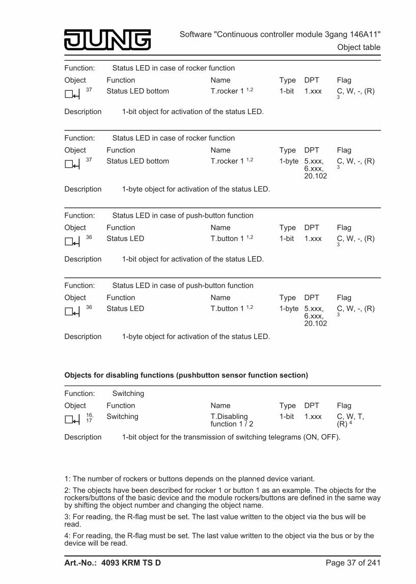
Function: Status LED in case of rocker function Object
h37
Function Status LED bottom
Name T.rocker 1 1,2
Type 1-bit
DPT 1.xxx
Flag C, W, -, (R) 3
Description 1-bit object for activation of the status LED.
Function: Status LED in case of rocker function Object
h37
Function Status LED bottom
Name T.rocker 1 1,2
Type 1-byte
DPT 5.xxx, 6.xxx, 20.102
Flag C, W, -, (R) 3
Description 1-byte object for activation of the status LED.
Function: Status LED in case of push-button function Object
h36
Function Status LED
Name T.button 1 1,2
Type 1-bit
DPT 1.xxx
Flag C, W, -, (R) 3
Description 1-bit object for activation of the status LED.
Function: Status LED in case of push-button function Object
h36
Function Status LED
Name T.button 1 1,2
Type 1-byte
DPT 5.xxx, 6.xxx, 20.102
Flag C, W, -, (R) 3
Description 1-byte object for activation of the status LED.
Objects for disabling functions (pushbutton sensor function section)
Function: Switching Object
h16, 17
Function Switching
Name T.Disabling function 1 / 2
Type 1-bit
DPT 1.xxx
Flag C, W, T, (R) 4
Description 1-bit object for the transmission of switching telegrams (ON, OFF).
1: The number of rockers or buttons depends on the planned device variant. 2: The objects have been described for rocker 1 or button 1 as an example. The objects for the rockers/buttons of the basic device and the module rockers/buttons are defined in the same way by shifting the object number and changing the object name. 3: For reading, the R-flag must be set. The last value written to the object via the bus will be read. 4: For reading, the R-flag must be set. The last value written to the object via the bus or by the device will be read.
Page 37 of 241
Software "Continuous controller module 3gang 146A11" Object table
Art.-No.: 4093 KRM TS D
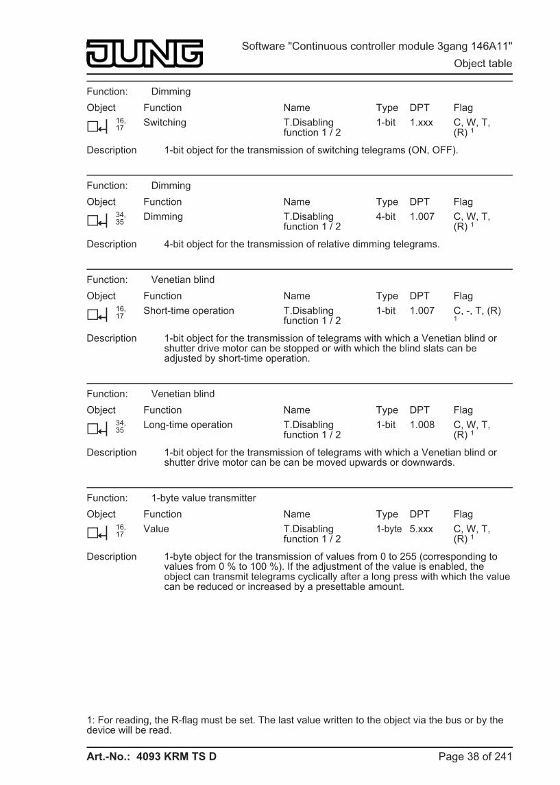
Function: Dimming Object
h16, 17
Function Switching
Name T.Disabling function 1 / 2
Type 1-bit
DPT 1.xxx
Flag C, W, T, (R) 1
Description 1-bit object for the transmission of switching telegrams (ON, OFF).
Function: Dimming Object
h34, 35
Function Dimming
Name T.Disabling function 1 / 2
Type 4-bit
DPT 1.007
Flag C, W, T, (R) 1
Description 4-bit object for the transmission of relative dimming telegrams.
Function: Venetian blind Object
h16, 17
Function Short-time operation
Name T.Disabling function 1 / 2
Type 1-bit
DPT 1.007
Flag C, -, T, (R) 1
Description 1-bit object for the transmission of telegrams with which a Venetian blind or shutter drive motor can be stopped or with which the blind slats can be adjusted by short-time operation.
Function: Venetian blind Object
h34, 35
Function Long-time operation
Name T.Disabling function 1 / 2
Type 1-bit
DPT 1.008
Flag C, W, T, (R) 1
Description 1-bit object for the transmission of telegrams with which a Venetian blind or shutter drive motor can be can be moved upwards or downwards.
Function: 1-byte value transmitter Object
h16, 17
Function Value
Name T.Disabling function 1 / 2
Type 1-byte
DPT 5.xxx
Flag C, W, T, (R) 1
Description 1-byte object for the transmission of values from 0 to 255 (corresponding to values from 0 % to 100 %). If the adjustment of the value is enabled, the object can transmit telegrams cyclically after a long press with which the value can be reduced or increased by a presettable amount.
1: For reading, the R-flag must be set. The last value written to the object via the bus or by the device will be read.
Page 38 of 241
Software "Continuous controller module 3gang 146A11" Object table
Art.-No.: 4093 KRM TS D
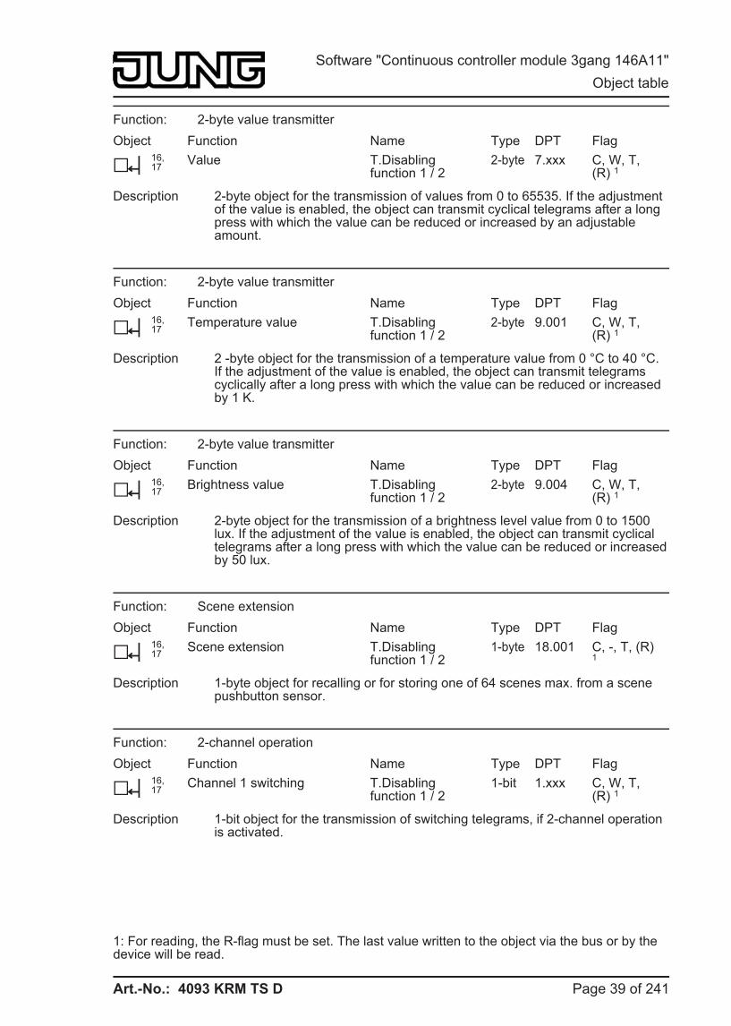
Function: 2-byte value transmitter Object
h16, 17
Function Value
Name T.Disabling function 1 / 2
Type 2-byte
DPT 7.xxx
Flag C, W, T, (R) 1
Description 2-byte object for the transmission of values from 0 to 65535. If the adjustment of the value is enabled, the object can transmit cyclical telegrams after a long press with which the value can be reduced or increased by an adjustable amount.
Function: 2-byte value transmitter Object
h16, 17
Function Temperature value
Name T.Disabling function 1 / 2
Type 2-byte
DPT 9.001
Flag C, W, T, (R) 1
Description 2 -byte object for the transmission of a temperature value from 0 °C to 40 °C. If the adjustment of the value is enabled, the object can transmit telegrams cyclically after a long press with which the value can be reduced or increased by 1 K.
Function: 2-byte value transmitter Object
h16, 17
Function Brightness value
Name T.Disabling function 1 / 2
Type 2-byte
DPT 9.004
Flag C, W, T, (R) 1
Description 2-byte object for the transmission of a brightness level value from 0 to 1500 lux. If the adjustment of the value is enabled, the object can transmit cyclical telegrams after a long press with which the value can be reduced or increased by 50 lux.
Function: Scene extension Object
h16, 17
Function Scene extension
Name T.Disabling function 1 / 2
Type 1-byte
DPT 18.001
Flag C, -, T, (R) 1
Description 1-byte object for recalling or for storing one of 64 scenes max. from a scene pushbutton sensor.
Function: 2-channel operation Object
h16, 17
Function Channel 1 switching
Name T.Disabling function 1 / 2
Type 1-bit
DPT 1.xxx
Flag C, W, T, (R) 1
Description 1-bit object for the transmission of switching telegrams, if 2-channel operation is activated.
1: For reading, the R-flag must be set. The last value written to the object via the bus or by the device will be read.
Page 39 of 241
Software "Continuous controller module 3gang 146A11" Object table
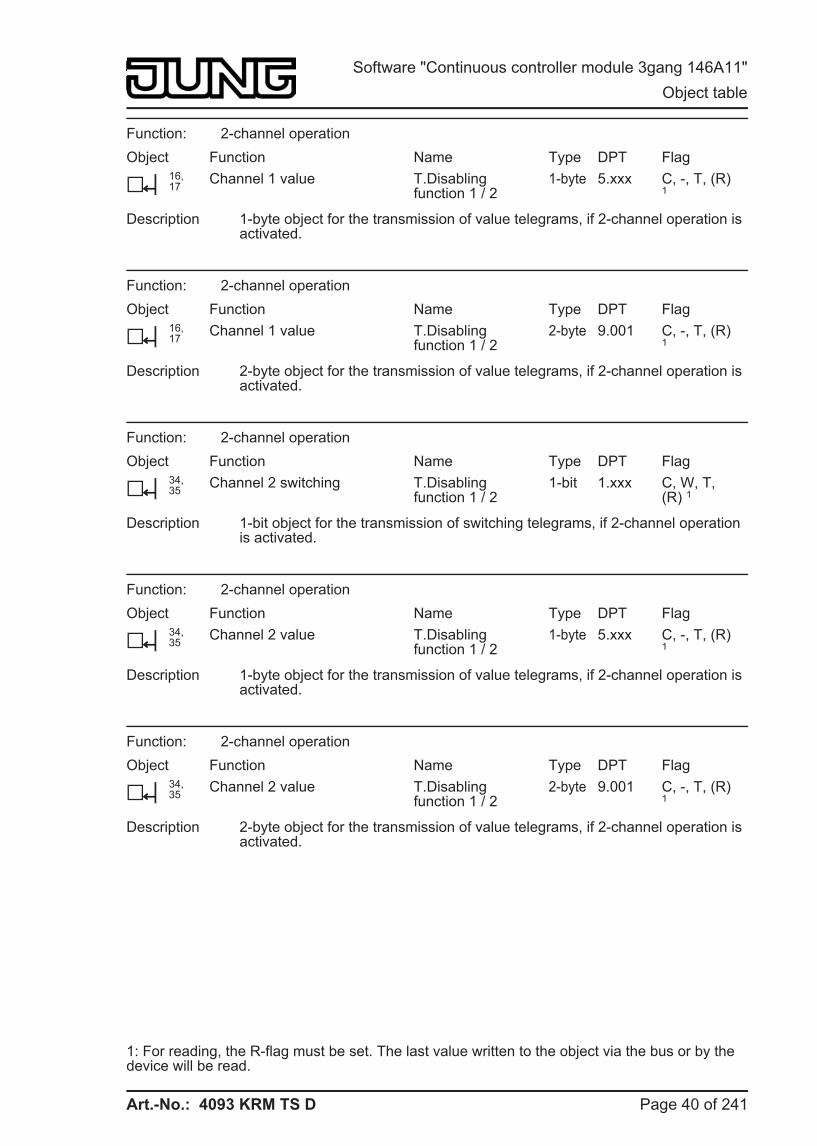
Art.-No.: 4093 KRM TS D
Function: 2-channel operation Object
h16, 17
Function Channel 1 value
Name T.Disabling function 1 / 2
Type 1-byte
DPT 5.xxx
Flag C, -, T, (R) 1
Description 1-byte object for the transmission of value telegrams, if 2-channel operation is activated.
Function: 2-channel operation Object
h16, 17
Function Channel 1 value
Name T.Disabling function 1 / 2
Type 2-byte
DPT 9.001
Flag C, -, T, (R) 1
Description 2-byte object for the transmission of value telegrams, if 2-channel operation is activated.
Function: 2-channel operation Object
h34, 35
Function Channel 2 switching
Name T.Disabling function 1 / 2
Type 1-bit
DPT 1.xxx
Flag C, W, T, (R) 1
Description 1-bit object for the transmission of switching telegrams, if 2-channel operation is activated.
Function: 2-channel operation Object
h34, 35
Function Channel 2 value
Name T.Disabling function 1 / 2
Type 1-byte
DPT 5.xxx
Flag C, -, T, (R) 1
Description 1-byte object for the transmission of value telegrams, if 2-channel operation is activated.
Function: 2-channel operation Object
h34, 35
Function Channel 2 value
Name T.Disabling function 1 / 2
Type 2-byte
DPT 9.001
Flag C, -, T, (R) 1
Description 2-byte object for the transmission of value telegrams, if 2-channel operation is activated.
1: For reading, the R-flag must be set. The last value written to the object via the bus or by the device will be read.
Page 40 of 241
Software "Continuous controller module 3gang 146A11" Object table
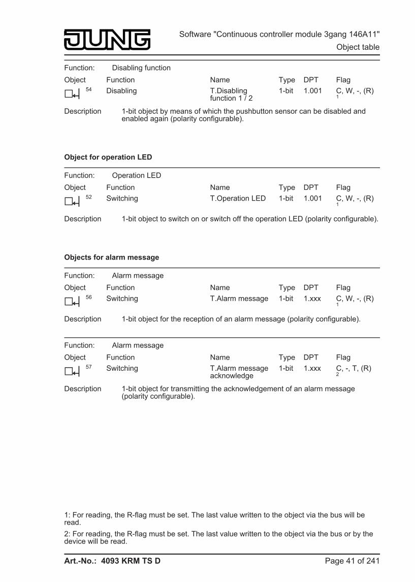
Art.-No.: 4093 KRM TS D
Function: Disabling function Object
h54
Function Disabling
Name T.Disabling function 1 / 2
Type 1-bit
DPT 1.001
Flag C, W, -, (R) 1
Description 1-bit object by means of which the pushbutton sensor can be disabled and enabled again (polarity configurable).
Object for operation LED
Function: Operation LED Object
h52
Function Switching
Name T.Operation LED
Type 1-bit
DPT 1.001
Flag C, W, -, (R) 1
Description 1-bit object to switch on or switch off the operation LED (polarity configurable).
Objects for alarm message
Function: Alarm message Object
h56
Function Switching
Name T.Alarm message
Type 1-bit
DPT 1.xxx
Flag C, W, -, (R) 1
Description 1-bit object for the reception of an alarm message (polarity configurable).
Function: Alarm message Object
h57
Function Switching
Name T.Alarm message acknowledge
Type 1-bit
DPT 1.xxx
Flag C, -, T, (R) 2
Description 1-bit object for transmitting the acknowledgement of an alarm message (polarity configurable).
1: For reading, the R-flag must be set. The last value written to the object via the bus will be read. 2: For reading, the R-flag must be set. The last value written to the object via the bus or by the device will be read.
Page 41 of 241
Software "Continuous controller module 3gang 146A11" Object table
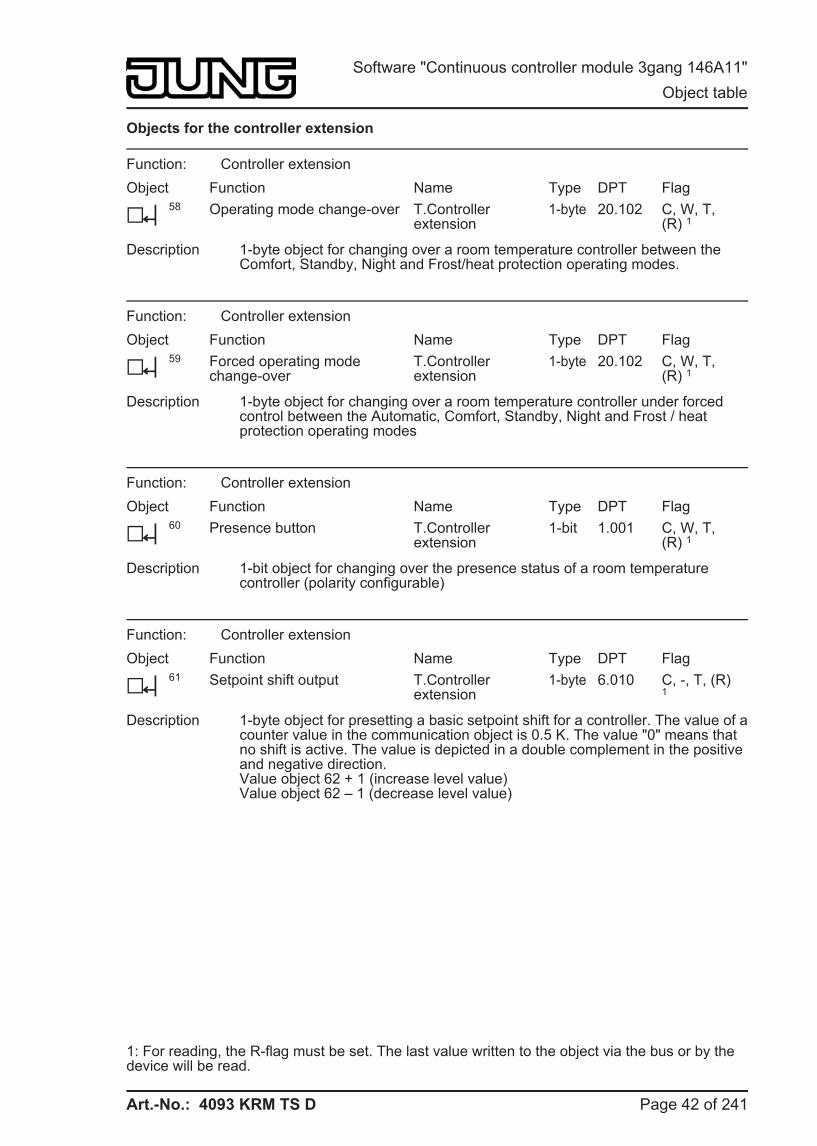
Art.-No.: 4093 KRM TS D
Objects for the controller extension
Function: Controller extension Object
h58
Function Operating mode change-over
Name T.Controllerextension
Type 1-byte
DPT 20.102
Flag C, W, T, (R) 1
Description 1-byte object for changing over a room temperature controller between the Comfort, Standby, Night and Frost/heat protection operating modes.
Function: Controller extension Object
h59
Function Forced operating mode change-over
Name T.Controllerextension
Type 1-byte
DPT 20.102
Flag C, W, T, (R) 1
Description 1-byte object for changing over a room temperature controller under forced control between the Automatic, Comfort, Standby, Night and Frost / heat protection operating modes
Function: Controller extension Object
h60
Function Presence button
Name T.Controllerextension
Type 1-bit
DPT 1.001
Flag C, W, T, (R) 1
Description 1-bit object for changing over the presence status of a room temperature controller (polarity configurable)
Function: Controller extension Object
h61
Function Setpoint shift output
Name T.Controllerextension
Type 1-byte
DPT 6.010
Flag C, -, T, (R) 1
Description 1-byte object for presetting a basic setpoint shift for a controller. The value of a counter value in the communication object is 0.5 K. The value "0" means that no shift is active. The value is depicted in a double complement in the positive and negative direction.Value object 62 + 1 (increase level value)Value object 62 – 1 (decrease level value)
1: For reading, the R-flag must be set. The last value written to the object via the bus or by the device will be read.
Page 42 of 241
Software "Continuous controller module 3gang 146A11" Object table
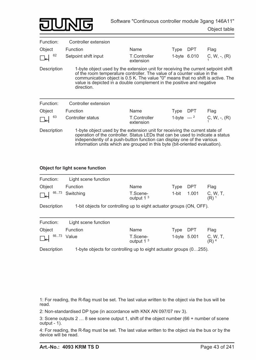
Art.-No.: 4093 KRM TS D
Function: Controller extension Object
h62
Function Setpoint shift input
Name T.Controllerextension
Type 1-byte
DPT 6.010
Flag C, W, -, (R) 1
Description 1-byte object used by the extension unit for receiving the current setpoint shift of the room temperature controller. The value of a counter value in the communication object is 0.5 K. The value "0" means that no shift is active. The value is depicted in a double complement in the positive and negative direction.
Function: Controller extension Object
h63
Function Controller status
Name T.Controllerextension
Type 1-byte
DPT --- 2
Flag C, W, -, (R) 1
Description 1-byte object used by the extension unit for receiving the current state of operation of the controller. Status LEDs that can be used to indicate a status independently of a push-button function can display one of the various information units which are grouped in this byte (bit-oriented evaluation).
Object for light scene function
Function: Light scene function Object
h66...73
Function Switching
Name T.Scene-output 1 3
Type 1-bit
DPT 1.001
Flag C, W, T, (R) 1
Description 1-bit objects for controlling up to eight actuator groups (ON, OFF).
Function: Light scene function Object
h66...73
Function Value
Name T.Scene-output 1 3
Type 1-byte
DPT 5.001
Flag C, W, T, (R) 4
Description 1-byte objects for controlling up to eight actuator groups (0…255).
1: For reading, the R-flag must be set. The last value written to the object via the bus will be read. 2: Non-standardised DP type (in accordance with KNX AN 097/07 rev 3). 3: Scene outputs 2 … 8 see scene output 1, shift of the object number (66 + number of scene output - 1). 4: For reading, the R-flag must be set. The last value written to the object via the bus or by the device will be read.
Page 43 of 241
Software "Continuous controller module 3gang 146A11" Object table
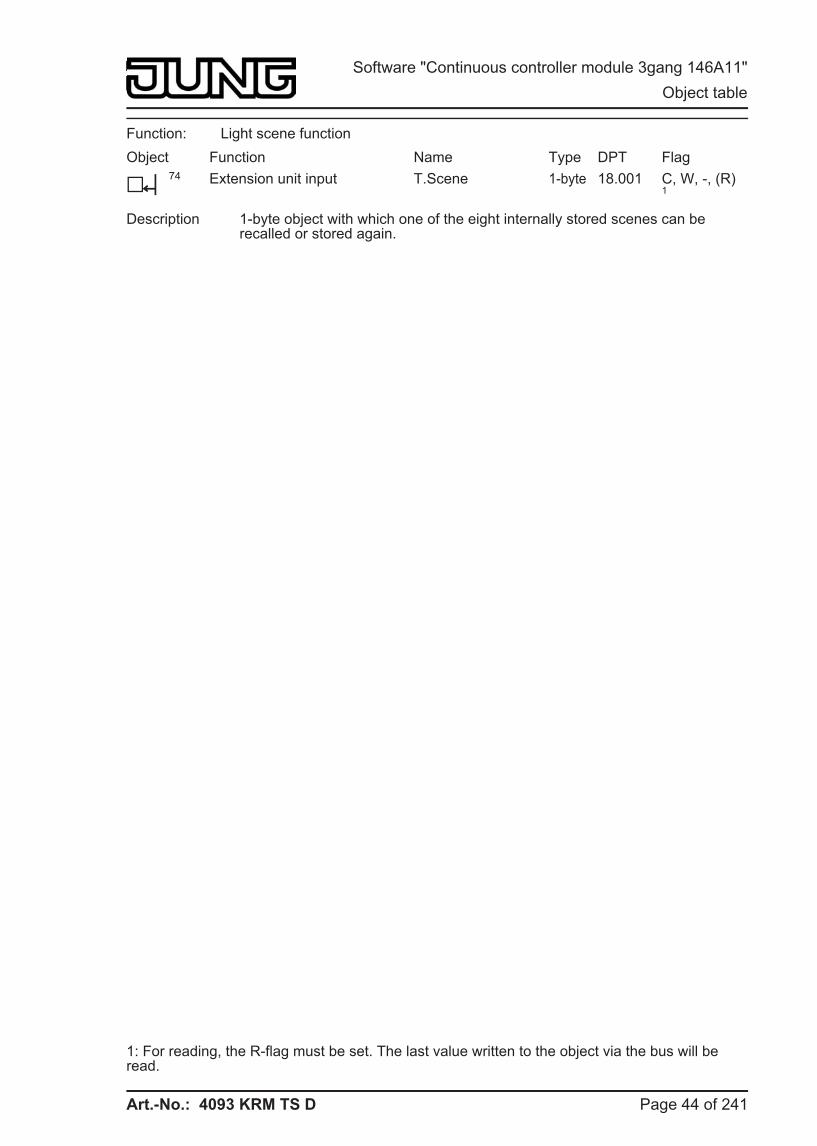
Art.-No.: 4093 KRM TS D
Function: Light scene function Object
h74
Function Extension unit input
Name T.Scene
Type 1-byte
DPT 18.001
Flag C, W, -, (R) 1
Description 1-byte object with which one of the eight internally stored scenes can be recalled or stored again.
1: For reading, the R-flag must be set. The last value written to the object via the bus will be read.
Page 44 of 241
Software "Continuous controller module 3gang 146A11" Object table
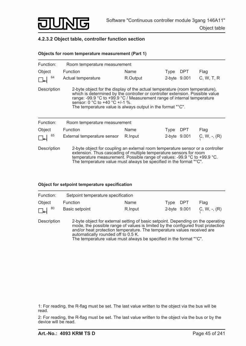
Art.-No.: 4093 KRM TS D
4.2.3.2 Object table, controller function section
Objects for room temperature measurement (Part 1)
Function: Room temperature measurement Object
h64
Function Actual temperature
Name R.Output
Type 2-byte
DPT 9.001
Flag C, W, T, R
Description 2-byte object for the display of the actual temperature (room temperature), which is determined by the controller or controller extension. Possible value range: -99.9 °C to +99.9 °C / Measurement range of internal temperature sensor: 0 °C to +40 °C +/-1 %.The temperature value is always output in the format "°C".
Function: Room temperature measurement Object
h65
Function External temperature sensor
Name R.Input
Type 2-byte
DPT 9.001
Flag C, W, -, (R) 1
Description 2-byte object for coupling an external room temperature sensor or a controller extension. Thus cascading of multiple temperature sensors for room temperature measurement. Possible range of values: -99.9 °C to +99.9 °C.The temperature value must always be specified in the format "°C".
Object for setpoint temperature specification
Function: Setpoint temperature specification Object
h80
Function Basic setpoint
Name R.Input
Type 2-byte
DPT 9.001
Flag C, W, -, (R) 1
Description 2-byte object for external setting of basic setpoint. Depending on the operating mode, the possible range of values is limited by the configured frost protection and/or heat protection temperature. The temperature values received are automatically rounded off to 0.5 K.The temperature value must always be specified in the format "°C".
1: For reading, the R-flag must be set. The last value written to the object via the bus will be read. 2: For reading, the R-flag must be set. The last value written to the object via the bus or by the device will be read.
Page 45 of 241
Software "Continuous controller module 3gang 146A11" Object table
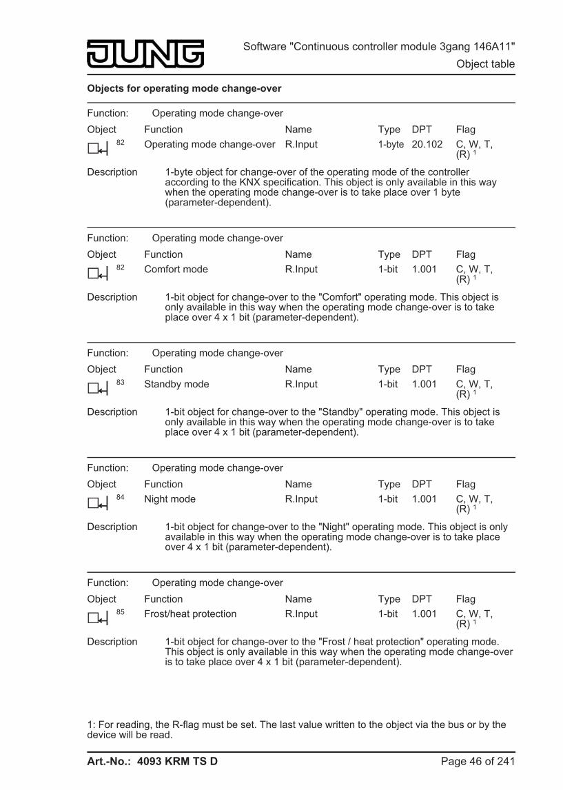
Art.-No.: 4093 KRM TS D
Objects for operating mode change-over
Function: Operating mode change-over Object
h82
Function Operating mode change-over
Name R.Input
Type 1-byte
DPT 20.102
Flag C, W, T, (R) 1
Description 1-byte object for change-over of the operating mode of the controller according to the KNX specification. This object is only available in this way when the operating mode change-over is to take place over 1 byte (parameter-dependent).
Function: Operating mode change-over Object
h82
Function Comfort mode
Name R.Input
Type 1-bit
DPT 1.001
Flag C, W, T, (R) 1
Description 1-bit object for change-over to the "Comfort" operating mode. This object is only available in this way when the operating mode change-over is to take place over 4 x 1 bit (parameter-dependent).
Function: Operating mode change-over Object
h83
Function Standby mode
Name R.Input
Type 1-bit
DPT 1.001
Flag C, W, T, (R) 1
Description 1-bit object for change-over to the "Standby" operating mode. This object is only available in this way when the operating mode change-over is to take place over 4 x 1 bit (parameter-dependent).
Function: Operating mode change-over Object
h84
Function Night mode
Name R.Input
Type 1-bit
DPT 1.001
Flag C, W, T, (R) 1
Description 1-bit object for change-over to the "Night" operating mode. This object is only available in this way when the operating mode change-over is to take place over 4 x 1 bit (parameter-dependent).
Function: Operating mode change-over Object
h85
Function Frost/heat protection
Name R.Input
Type 1-bit
DPT 1.001
Flag C, W, T, (R) 1
Description 1-bit object for change-over to the "Frost / heat protection" operating mode. This object is only available in this way when the operating mode change-over is to take place over 4 x 1 bit (parameter-dependent).
1: For reading, the R-flag must be set. The last value written to the object via the bus or by the device will be read.
Page 46 of 241
Software "Continuous controller module 3gang 146A11" Object table
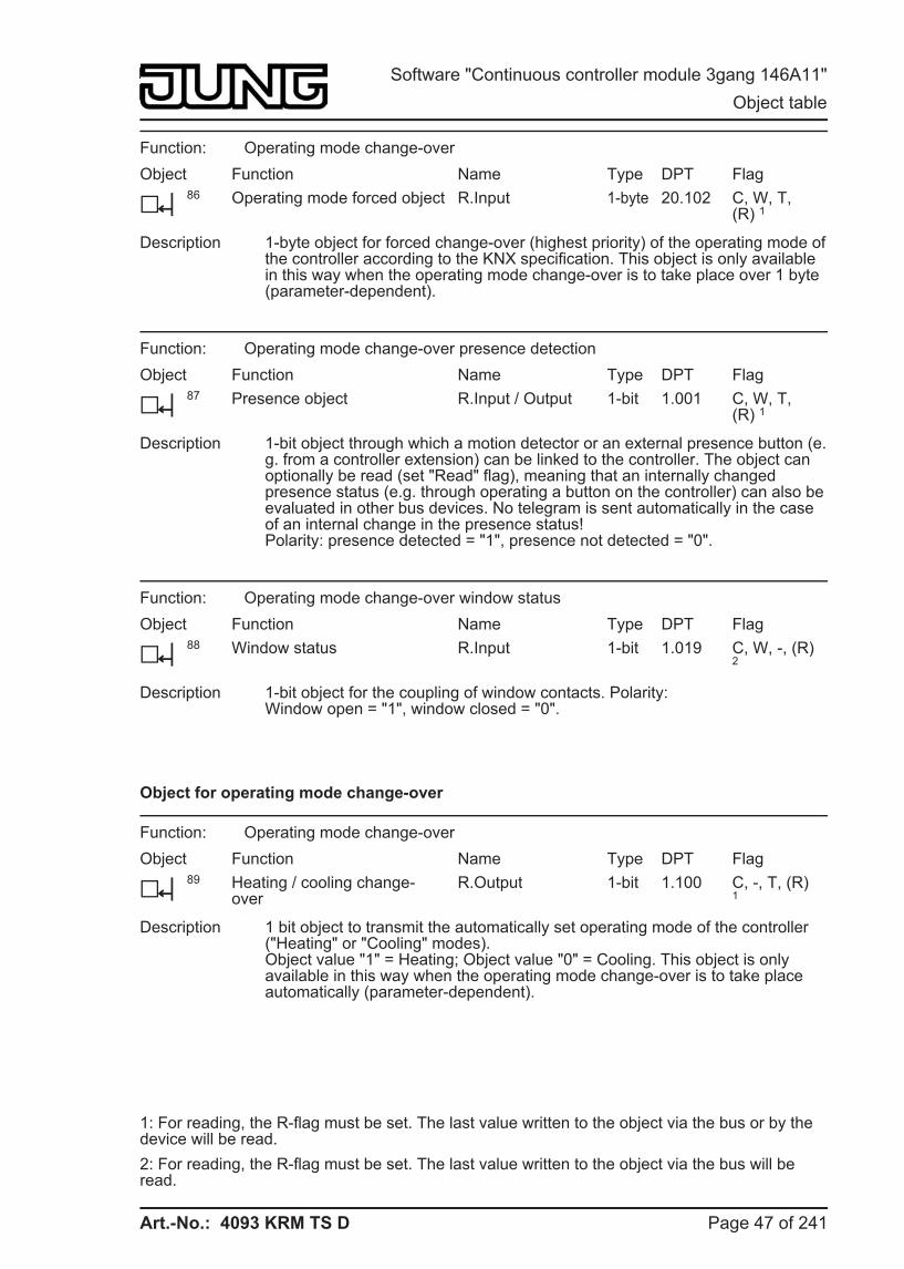
Art.-No.: 4093 KRM TS D
Function: Operating mode change-over Object
h86
Function Operating mode forced object
Name R.Input
Type 1-byte
DPT 20.102
Flag C, W, T, (R) 1
Description 1-byte object for forced change-over (highest priority) of the operating mode of the controller according to the KNX specification. This object is only available in this way when the operating mode change-over is to take place over 1 byte (parameter-dependent).
Function: Operating mode change-over presence detection Object
h87
Function Presence object
Name R.Input / Output
Type 1-bit
DPT 1.001
Flag C, W, T, (R) 1
Description 1-bit object through which a motion detector or an external presence button (e.g. from a controller extension) can be linked to the controller. The object can optionally be read (set "Read" flag), meaning that an internally changed presence status (e.g. through operating a button on the controller) can also be evaluated in other bus devices. No telegram is sent automatically in the case of an internal change in the presence status!Polarity: presence detected = "1", presence not detected = "0".
Function: Operating mode change-over window status Object
h88
Function Window status
Name R.Input
Type 1-bit
DPT 1.019
Flag C, W, -, (R) 2
Description 1-bit object for the coupling of window contacts. Polarity: Window open = "1", window closed = "0".
Object for operating mode change-over
Function: Operating mode change-over Object
h89
Function Heating / cooling change-over
Name R.Output
Type 1-bit
DPT 1.100
Flag C, -, T, (R) 1
Description 1 bit object to transmit the automatically set operating mode of the controller ("Heating" or "Cooling" modes). Object value "1" = Heating; Object value "0" = Cooling. This object is only available in this way when the operating mode change-over is to take place automatically (parameter-dependent).
1: For reading, the R-flag must be set. The last value written to the object via the bus or by the device will be read. 2: For reading, the R-flag must be set. The last value written to the object via the bus will be read.
Page 47 of 241
Software "Continuous controller module 3gang 146A11" Object table
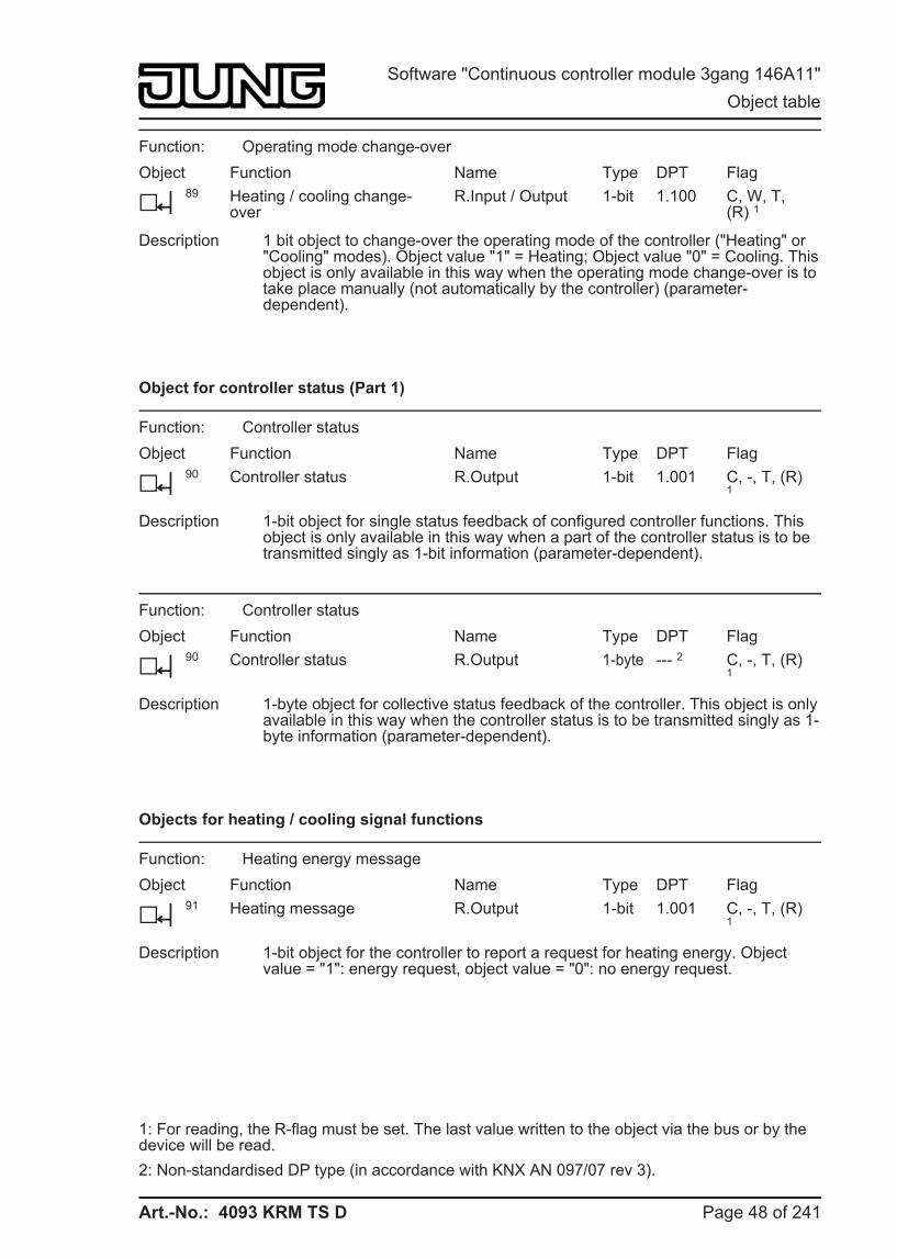
Art.-No.: 4093 KRM TS D
Function: Operating mode change-over Object
h89
Function Heating / cooling change-over
Name R.Input / Output
Type 1-bit
DPT 1.100
Flag C, W, T, (R) 1
Description 1 bit object to change-over the operating mode of the controller ("Heating" or "Cooling" modes). Object value "1" = Heating; Object value "0" = Cooling. This object is only available in this way when the operating mode change-over is to take place manually (not automatically by the controller) (parameter-dependent).
Object for controller status (Part 1)
Function: Controller status Object
h90
Function Controller status
Name R.Output
Type 1-bit
DPT 1.001
Flag C, -, T, (R) 1
Description 1-bit object for single status feedback of configured controller functions. This object is only available in this way when a part of the controller status is to be transmitted singly as 1-bit information (parameter-dependent).
Function: Controller status Object
h90
Function Controller status
Name R.Output
Type 1-byte
DPT --- 2
Flag C, -, T, (R) 1
Description 1-byte object for collective status feedback of the controller. This object is only available in this way when the controller status is to be transmitted singly as 1-byte information (parameter-dependent).
Objects for heating / cooling signal functions
Function: Heating energy message Object
h91
Function Heating message
Name R.Output
Type 1-bit
DPT 1.001
Flag C, -, T, (R) 1
Description 1-bit object for the controller to report a request for heating energy. Object value = "1": energy request, object value = "0": no energy request.
1: For reading, the R-flag must be set. The last value written to the object via the bus or by the device will be read. 2: Non-standardised DP type (in accordance with KNX AN 097/07 rev 3).
Page 48 of 241
Software "Continuous controller module 3gang 146A11" Object table
Art.-No.: 4093 KRM TS D
Function: Cooling energy message Object
h92
Function Cooling message
Name R.Output
Type 1-bit
DPT 1.001
Flag C, -, T, (R) 1
Description 1-bit object for the controller to report a request for cooling energy. Object value = "1": energy request, object value = "0": no energy request.
Objects for controller disabling functions
Function: Disable controller Object
h94
Function Disable controller
Name R.Input
Type 1-bit
DPT 1.001
Flag C, W, -, (R) 2
Description 1-bit object for deactivating the controller (activating dew point operation). Polarity: Controller deactivated = "1", controller activated = "0".
Function: Disable controller Object
h95
Function Disable additional level
Name R.Input
Type 1-bit
DPT 1.001
Flag C, W, -, (R) 2
Description 1-bit object for deactivating the additional level of the controller. Polarity: Additional level deactivated = "1", additional level activated = "0". This object is only available in this way if two-level heating or cooling operation is configured.
Object for heating command value output and combined valve heating/cooling
Function: Command value Object
h96
Function Command value for heating / command value, basic heating
Name R.Output
Type 1-byte
DPT 5.001
Flag C, -, T, (R) 1
Description 1-byte object to output the continuous command value of the heating mode. In two-level heating mode, command value output for the basic heating. This object is only available in this way if the type of feedback control is configured to "Continuous PI feedback control".
1: For reading, the R-flag must be set. The last value written to the object via the bus or by the device will be read. 2: For reading, the R-flag must be set. The last value written to the object via the bus will be read.
Page 49 of 241
Software "Continuous controller module 3gang 146A11" Object table
Art.-No.: 4093 KRM TS D
Function: Command value Object
h96
Function Command value for heating (PWM) / command value, basic heating (PWM)
Name R.Output
Type 1-bit
DPT 1.001
Flag C, -, T, (R) 1
Description 1-bit object to output the PWM command value of the heating mode. In two-level heating mode, command value output for the basic heating. This object is only available in this way if the type of feedback control is configured to "Switching PI feedback control (PWM)".
Function: Command value Object
h96
Function Command value for heating / command value, basic heating
Name R.Output
Type 1-bit
DPT 1.001
Flag C, -, T, (R) 1
Description 1-bit object to output the switching command value of the heating mode. In two-level heating mode, command value output for the basic heating. This object is only available in this way if the type of feedback control is configured to "Switching 2-point feedback control".
Function: Command value Object
h96
Function Command value for heating/cooling / command value, basic level
Name R.Output
Type 1-byte
DPT 5.001
Flag C, -, T, (R) 1
Description 1-byte object to output the combined continuous command value of the heating and cooling mode. In two-level heating/cooling mode, command value output for the basic level This object is only available in this way if the command values for heating and cooling mode are output to a shared object (parameter-dependent). The type of feedback control must also be configured to "Continuous PI feedback control".
Function: Command value Object
h96
Function Command value for heating/cooling (PWM) / command value, basic level (PWM)
Name R.Output
Type 1-bit
DPT 1.001
Flag C, -, T, (R) 1
Description 1-bit object to output the combined PWM command value of the heating and cooling mode. In two-level heating/cooling mode, command value output for the basic level This object is only available in this way if the command values for heating and cooling mode are output to a shared object (parameter-dependent). The type of feedback control must also be configured to "Switching PI feedback control (PWM)".
1: For reading, the R-flag must be set. The last value written to the object via the bus or by the device will be read.
Page 50 of 241
Software "Continuous controller module 3gang 146A11" Object table
Art.-No.: 4093 KRM TS D
Function: Command value Object
h96
Function Command value for heating/cooling / command value, basic level
Name R.Output
Type 1-bit
DPT 1.001
Flag C, -, T, (R) 1
Description 1-bit object to output the combined switching command value of the heating and cooling mode. In two-level heating/cooling mode, command value output for the basic level This object is only available in this way if the command values for heating and cooling mode are output to a shared object (parameter-dependent). The type of feedback control must also be configured to "Switching 2-point feedback control".
Object for command value output, additional heating and combined valve additional heating/cooling
Function: Command value Object
h97
Function Command value, additional heating
Name R.Output
Type 1-byte
DPT 5.001
Flag C, -, T, (R) 1
Description 1-byte object to output the continuous command value for additional heating in two-level operation. This object is only available in this way if the type of feedback control is configured to "Continuous PI feedback control".
Function: Command value Object
h97
Function Command value, additional heating (PWM)
Name R.Output
Type 1-bit
DPT 1.001
Flag C, -, T, (R) 1
Description 1-bit object to output the continuous PWM command value for additional heating in two-level operation. This object is only available in this way if the type of feedback control is configured to "Switching PI feedback control (PWM)".
Function: Command value Object
h97
Function Command value, additional heating
Name R.Output
Type 1-bit
DPT 1.001
Flag C, -, T, (R) 1
Description 1-byte object to output the switching command value for additional heating in two-level operation. This object is only available in this way if the type of feedback control is configured to "Switching 2-point feedback control".
1: For reading, the R-flag must be set. The last value written to the object via the bus or by the device will be read.
Page 51 of 241
Software "Continuous controller module 3gang 146A11" Object table
Art.-No.: 4093 KRM TS D
Function: Command value Object
h97
Function Command value, additional level
Name R.Output
Type 1-byte
DPT 5.001
Flag C, -, T, (R) 1
Description 1-byte object to output the combined continuous command value for additional level in two-level operation. This object is only available in this way if the command values for heating and cooling mode are output to a shared object (parameter-dependent). The type of feedback control must also be configured to "Continuous PI feedback control".
Function: Command value Object
h97
Function Command value, additional level (PWM)
Name R.Output
Type 1-bit
DPT 1.001
Flag C, -, T, (R) 1
Description 1-bit object to output the combined switching PWM command value for additional level in two-level operation. This object is only available in this way if the command values for heating and cooling mode are output to a shared object (parameter-dependent). The type of feedback control must also be configured to "Switching PI feedback control (PWM)".
Function: Command value Object
h97
Function Command value, additional level
Name R.Output
Type 1-bit
DPT 1.001
Flag C, -, T, (R) 1
Description 1-bit object to output the combined switching command value for additional level in two-level operation. This object is only available in this way if the command values for heating and cooling mode are output to a shared object (parameter-dependent). The type of feedback control must also be configured to "Switching 2-point feedback control".
Object for command value output, cooling
Function: Command value Object
h98
Function Command value for cooling / command value, basic cooling
Name R.Output
Type 1-byte
DPT 5.001
Flag C, -, T, (R) 1
Description 1-byte object to output the continuous command value of the cooling mode. In two-level cooling mode, command value output for the basic cooling. This object is only available in this way if the type of feedback control is configured to "Continuous PI feedback control".
1: For reading, the R-flag must be set. The last value written to the object via the bus or by the device will be read.
Page 52 of 241
Software "Continuous controller module 3gang 146A11" Object table
Art.-No.: 4093 KRM TS D
Function: Command value Object
h98
Function Command value for cooling (PWM) / command value, basic cooling (PWM)
Name R.Output
Type 1-bit
DPT 1.001
Flag C, -, T, (R) 1
Description 1-bit object to output the PWM command value of the cooling mode. In two-level cooling mode, command value output for the basic cooling. This object is only available in this way if the type of feedback control is configured to "Switching PI feedback control (PWM)".
Function: Command value Object
h98
Function Command value for cooling / command value, basic cooling
Name R.Output
Type 1-bit
DPT 1.001
Flag C, -, T, (R) 1
Description 1-bit object to output the switching command value of the cooling mode. In two-level cooling mode, command value output for the basic cooling. This object is only available in this way if the type of feedback control is configured to "Switching 2-point feedback control".
Object for command value output, additional cooling
Function: Command value Object
h99
Function Command value, additional cooling
Name R.Output
Type 1-byte
DPT 5.001
Flag C, -, T, (R) 1
Description 1-byte object to output the continuous command value for additional cooling in two-level operation. This object is only available in this way if the type of feedback control is configured to "Continuous PI feedback control".
Function: Command value Object
h99
Function Command value, additional cooling (PWM)
Name R.Output
Type 1-bit
DPT 1.001
Flag C, -, T, (R) 1
Description 1-bit object to output the continuous PWM command value for additional cooling in two-level operation. This object is only available in this way if the type of feedback control is configured to "Switching PI feedback control (PWM)".
1: For reading, the R-flag must be set. The last value written to the object via the bus or by the device will be read.
Page 53 of 241
Software "Continuous controller module 3gang 146A11" Object table
Art.-No.: 4093 KRM TS D
Function: Command value Object
h99
Function Command value, additional cooling
Name R.Output
Type 1-bit
DPT 1.001
Flag C, -, T, (R) 1
Description 1-byte object to output the switching command value for additional cooling in two-level operation. This object is only available in this way if the type of feedback control is configured to "Switching 2-point feedback control".
Object for additional PWM heating command value output and combined valve PWM additional heating/cooling
Function: Command value Object
h100
Function PWM command value for heating / PWM command value, basic heating
Name R.Output
Type 1-byte
DPT 5.001
Flag C, -, T, (R) 1
Description 1-byte object to output the internal continuous command value of a PWM controller of the heating mode. In two-level heating mode, command value output for the basic heating. This object is only available in this way if the type of feedback control is configured to "Switching PI feedback control (PWM)". In addition to the switching 1 bit command value of the PWM, the calculated continuous command value of the controller can also be transmitted to the bus and displayed, e.g. in a visualisation.
Function: Command value Object
h100
Function PWM command value for heating/cooling / PWM command value, basic level
Name R.Output
Type 1-byte
DPT 5.001
Flag C, -, T, (R) 1
Description 1-byte object to output the combined continuous command value of a PWM controller of the heating and cooling mode. In two-level heating/cooling mode, command value output for the basic level This object is only available in this way if the command values for heating and cooling mode are output to a shared object (parameter-dependent). The type of feedback control must also be configured to "Switching PI feedback control (PWM)". In addition to the switching 1 bit command value of the PWM, the calculated continuous command value of the controller can also be transmitted to the bus and displayed, e.g. in a visualisation.
1: For reading, the R-flag must be set. The last value written to the object via the bus or by the device will be read.
Page 54 of 241
Software "Continuous controller module 3gang 146A11" Object table
Art.-No.: 4093 KRM TS D
Object for additional command value output, PWM additional heating and combined valve PWM additional heating/cooling
Function: Command value Object
h101
Function PWM command value, additional heating
Name R.Output
Type 1-byte
DPT 5.001
Flag C, -, T, (R) 1
Description 1-byte object to output the internal continuous command value of a PWM controller for additional heating in two-level operation. This object is only available in this way if the type of feedback control is configured to "Continuous PI feedback control". In addition to the switching 1 bit command value of the PWM, the calculated continuous command value of the controller can also be transmitted to the bus and displayed, e.g. in a visualisation.
Function: Command value Object
h101
Function PWM command value, additional level
Name R.Output
Type 1-byte
DPT 5.001
Flag C, -, T, (R) 1
Description 1-byte object to output the combined continuous command value of a PWM feedback controller for additional level in two-level operation. This object is only available in this way if the command values for heating and cooling mode are output to a shared object (parameter-dependent). The type of feedback control must also be configured to "Switching PI feedback control (PWM)". In addition to the switching 1 bit command value of the PWM, the calculated continuous command value of the controller can also be transmitted to the bus and displayed, e.g. in a visualisation.
Object for additional command value output, PWM cooling
Function: Command value Object
h102
Function PWM command value for cooling / PWM command value, basic cooling
Name R.Output
Type 1-byte
DPT 5.001
Flag C, -, T, (R) 1
Description 1-byte object to output the internal continuous command value of a PWM feedback controller of the cooling mode. In two-level cooling mode, command value output for the basic cooling. This object is only available in this way if the type of feedback control is configured to "Switching PI feedback control (PWM)". In addition to the switching 1 bit command value of the PWM, the calculated continuous command value of the controller can also be transmitted to the bus and displayed, e.g. in a visualisation.
1: For reading, the R-flag must be set. The last value written to the object via the bus or by the device will be read.
Page 55 of 241
Software "Continuous controller module 3gang 146A11" Object table
Art.-No.: 4093 KRM TS D
Object for additional command value output, PWM additional cooling
Function: Command value Object
h103
Function PWM command value, additional cooling
Name R.Output
Type 1-byte
DPT 5.001
Flag C, -, T, (R) 1
Description 1-byte object to output the internal continuous command value of a PWM feedback controller for additional cooling in two-level operation. This object is only available in this way if the type of feedback control is configured to "Switching PI feedback control (PWM)". In addition to the switching 1 bit command value of the PWM, the calculated continuous command value of the controller can also be transmitted to the bus and displayed, e.g. in a visualisation.
Object for outputting the setpoint temperature
Function: Setpoint temperature Object
h104
Function Setpoint temperature
Name R.Output
Type 2-byte
DPT 9.001
Flag C, -, T, R
Description 2-byte object for the output of the current temperature setpoint. Depending on the operating mode, the possible range of values is limited by the configured frost protection and/or heat protection temperature.The temperature value is always output in the format "°C".
Object for basic setpoint shift
Function: Basic setpoint shift Object
h106
Function Acknowledge setpoint shift
Name R.Output
Type 1-byte
DPT 6.010
Flag C, -, T, R
Description 1-byte object for giving feedback on the current setpoint shifting. The value of a counter value in the communication object is 0.5 K. The value "0" means that no shift is active. The value is depicted in a double complement in the positive and negative direction.
1: For reading, the R-flag must be set. The last value written to the object via the bus or by the device will be read.
Page 56 of 241
Software "Continuous controller module 3gang 146A11" Object table
Art.-No.: 4093 KRM TS D
Function: Basic setpoint shift Object
h107
Function Setpoint shift specification
Name R.Input
Type 1-byte
DPT 6.010
Flag C, W, -, (R) 1
Description 1-byte object for setting a basic setpoint shifting, e.g. via a controller extension. The value of a counter value in the communication object is 0.5 K. The value "0" means that no shift is active. The value is depicted in a double complement in the positive and negative direction.In case the limits of the value range are exceeded by the preset external value, the controller will automatically reset the received value to the minimum and maximum limits.
Object for controller status (Part 2)
Function: Controller status Object
h108
Function Status signal addition
Name R.Output
Type 1-byte
DPT --- 2
Flag C, -, T, (R) 3
Description 1-byte object for extended collective status feedback of the controller. For connecting controller extensions.
Object for room temperature measurement (Part 2)
Function: Room temperature measurement Object
h109
Function Actual temperature not adjusted
Name R.Output
Type 2-byte
DPT 9.001
Flag C, -, T, R
Description 2-byte object for following-up the determined and unadjusted room temperature value.The temperature value is always output in the format "°C".
1: For reading, the R-flag must be set. The last value written to the object via the bus will be read. 2: Non-standardised DP type. 3: For reading, the R-flag must be set. The last value written to the object via the bus or by the device will be read.
Page 57 of 241
Software "Continuous controller module 3gang 146A11" Object table
Art.-No.: 4093 KRM TS D
Objects for fan control (Part 1)
Function: Fan controller Object
h110
Function Ventilation, automatic/manual
Name R.Input
Type 1-bit
DPT 1.001
Flag C, W, T, (R) 1
Description 1-bit object to change-over the operating mode of the fan controller (configurable polarity). When the operating mode is changed over using a push-button function, a telegram matching the current status is transmitted to the bus.
Function: Fan controller Object
h111
Function Ventilation, fan level 1-8
Name R.Output
Type 1-bit
DPT 5.010
Flag C, -, T, R
Description 1-byte object for value-guided activation of the fan levels. This object is only available in this way when the fan control is to take place over 1 byte (parameter-dependent).
Function: Fan controller Object
h111
Function Ventilation, fan level 1
Name R.Output
Type 1-bit
DPT 1.001
Flag C, -, T, R
Description 1-bit object for switching activation of the first fan level. This object is only available in this way when the fan control is to take place over 3 x 1 bit and at least one fan level is enabled (parameter-dependent).
Function: Fan controller Object
h112
Function Ventilation, fan level 2
Name R.Output
Type 1-bit
DPT 1.001
Flag C, -, T, R
Description 1-bit object for switching activation of the second fan level. This object is only available when the fan control is to take place over 3 x 1 bit and at least two fan levels are enabled (parameter-dependent).
Function: Fan controller Object
h113
Function Ventilation, fan level 3
Name R.Output
Type 1-bit
DPT 1.001
Flag C, -, T, R
Description 1-bit object for switching activation of the third fan level. This object is only available when the fan control is to take place over 3 x 1 bit and at least three fan levels are enabled (parameter-dependent).
1: For reading, the R-flag must be set. The last value written to the object via the bus or by the device will be read.
Page 58 of 241
Software "Continuous controller module 3gang 146A11" Object table
Art.-No.: 4093 KRM TS D
Function: Fan controller Object
h114
Function Ventilation, fan level 4
Name R.Output
Type 1-bit
DPT 1.001
Flag C, -, T, R
Description 1-bit object for switching activation of the fourth fan level. This object is only available when the fan control is to take place over 3 x 1 bit and at least four fan levels are enabled (parameter-dependent).
Function: Fan controller Object
h115
Function Ventilation, fan level 5
Name R.Output
Type 1-bit
DPT 1.001
Flag C, -, T, R
Description 1-bit object for switching activation of the fifth fan level. This object is only available when the fan control is to take place over 3 x 1 bit and at least five fan levels are enabled (parameter-dependent).
Function: Fan controller Object
h116
Function Ventilation, fan level 6
Name R.Output
Type 1-bit
DPT 1.001
Flag C, -, T, R
Description 1-bit object for switching activation of the sixth fan level. This object is only available when the fan control is to take place over 3 x 1 bit and at least six fan levels are enabled (parameter-dependent).
Function: Fan controller Object
h117
Function Ventilation, fan level 7
Name R.Output
Type 1-bit
DPT 1.001
Flag C, -, T, R
Description 1-bit object for switching activation of the seventh fan level. This object is only available when the fan control is to take place over 3 x 1 bit and at least seven fan levels are enabled (parameter-dependent).
Function: Fan controller Object
h118
Function Ventilation, fan level 8
Name R.Output
Type 1-bit
DPT 1.001
Flag C, -, T, R
Description 1-bit object for switching activation of the eighth fan level. This object is only available when the fan control is to take place over 3 x 1 bit and at least eight fan levels are enabled (parameter-dependent).
Page 59 of 241
Software "Continuous controller module 3gang 146A11" Object table
Art.-No.: 4093 KRM TS D
Function: Fan controller Object
h119
Function Ventilation, forced position
Name R.Input
Type 1-bit
DPT 1.001
Flag C, W, -, (R) 1
Description 1-bit object for activation of the fan forced position. Polarity: Forced position ON = "1"; Forced position OFF = "0".
Function: Fan controller Object
h120
Function Ventilation, level limit
Name R.Input
Type 1-bit
DPT 1.001
Flag C, W, -, (R) 1
Description 1-bit object for activation of the fan level limitation. Polarity: Fan level limitation ON = "1"; Fan level limitation OFF = "0".
Function: Fan controller Object
h121
Function Ventilation, fan protection
Name R.Input
Type 1-bit
DPT 1.001
Flag C, W, -, (R) 1
Description 1-bit object for activating the fan protection. Polarity: Fan protection ON = "1" / Fan protection OFF = "0".
Object for detecting the outdoor temperature
Function: Outdoor temperature Object
h122
Function Outdoor temperature
Name R.Input
Type 2-byte
DPT 9.001
Flag C, W, T, (R) 2
Description 2-byte object for detecting the outdoor temperature The received value is used solely for the display. Possible range of values: -99.9 °C to +99.9 °C.The temperature value must always be specified in the format "°C".
1: For reading, the R-flag must be set. The last value written to the object via the bus will be read. 2: For reading, the R-flag must be set. The last value written to the object via the bus or by the device will be read.
Page 60 of 241
Software "Continuous controller module 3gang 146A11" Object table
Art.-No.: 4093 KRM TS D
Object for limiting the setpoint temperature
Function: Setpoint temperature limit Object
h123
Function Limit of cooling setpoint temperature
Name R.Input
Type 1-bit
DPT 1.001
Flag C, W, -, (R) 1
Description 1-bit object for activating the setpoint temperature limit. Polarity: Setpoint temperature limit ON = "1"; Setpoint temperature limit OFF = "0".
Object for limiting the floor temperature
Function: Floor temperature limitation Object
h124
Function Floor temperature
Name R.Input
Type 2-byte
DPT 9.001
Flag C, W, -, (R) 1
Description 2-byte object for coupling an external temperature sensor for floor temperature limitation.The temperature value must always be specified in the format "°C".
Objects for fan control (Part 2)
Function: Fan controller Object
h129
Function Ventilation visualisation
Name R.Output
Type 1-byte
DPT 5.010
Flag C, -, T, R
Description 1-byte object for additional value-guided acknowledgement of the active fan level. Value meaning: "0" = Fan OFF, "1" = level 1 active, "2" = level 2 active, ..., "8" = level 8 active.
1: For reading, the R-flag must be set. The last value written to the object via the bus will be read.
Page 61 of 241
Software "Continuous controller module 3gang 146A11" Object table
Art.-No.: 4093 KRM TS D
4.2.3.3 Display object table
Objects for display control
Function: Time Object
h130
Function Time
Name D.Input
Type 3-byte
DPT 10.001
Flag C, W, T, (R) 1
Description 3-byte object for receiving the current time via the bus. The time can be shown on the display (parameter-dependent).
Function: Backlighting Object
h133
Function Backlighting On/Off
Name D.Input
Type 1-bit
DPT 1.001
Flag C, W, -, (R) 2
Description 1-bit object to switch the backlighting of the LC display (polarity configurable).
Function: Backlighting Object
h133
Function Backlighting brightness
Name D.Input
Type 1-byte
DPT 5.001
Flag C, W, -, (R) 2
Description 1-byte object for presetting a brightness for the backlighting of the LC display.
Additional objects for display control with a controller extension
Function: Command value Object
h100
Function Command value for heating
Name D. Input Controller ext.
Type 1-byte
DPT 5.001
Flag C, W, -, (R) 2
Description 1-byte object to evaluate the continuous command value of the heating mode on the controller extension. This object is only available in this way if the adaptation of the type of feedback control is configured to "Continuous PI feedback control" in the controller extension. This object should be connected to the main controller object with the same function.
1: For reading, the R-flag must be set. The last value written to the object via the bus or by the device will be read. 2: For reading, the R-flag must be set. The last value written to the object via the bus will be read.
Page 62 of 241
Software "Continuous controller module 3gang 146A11" Object table
Art.-No.: 4093 KRM TS D
Function: Command value Object
h100
Function Command value for heating/cooling
Name D. Input Controller ext.
Type 1-byte
DPT 5.001
Flag C, W, -, (R) 1
Description 1-byte object to evaluate the combined continuous command value of the heating and cooling mode on the controller extension. This object is only available in this way if the controller outputs the command values for heating and cooling mode to a shared object and the mode adaptation of feedback control is configured to "Continuous PI feedback control" in the controller extension. This object should be connected to the main controller object with the same function.
Function: Command value Object
h100
Function Command value for heating (PWM)
Name D. Input Controller ext.
Type 1-bit
DPT 1.001
Flag C, W, -, (R) 1
Description 1-bit object to evaluate the switching PWM command value of the heating mode on the controller extension. This object is only available in this way if the adaptation of control is configured to "Switching PI feedback control (PWM)" in the controller extension. This object should be connected to the main controller object with the same function.
Function: Command value Object
h100
Function Command value for heating/cooling (PWM)
Name D. Input Controller ext.
Type 1-bit
DPT 1.001
Flag C, W, -, (R) 1
Description 1-bit object to evaluate the combined switching PWM command value of the heating and cooling mode on the controller extension. This object is only available in this way if the controller outputs the command values for heating and cooling mode to a shared object and the mode adaptation of control is configured to "Switching PI feedback control (PWM)" in the controller extension. This object should be connected to the main controller object with the same function.
Function: Command value Object
h100
Function Command value for heating
Name D. Input Controller ext.
Type 1-bit
DPT 1.001
Flag C, W, -, (R) 1
Description 1-byte object to evaluate the switching command value of the heating mode on the controller extension. This object is only available in this way if the adaptation of the type of feedback control is configured to "Switching 2-point feedback control" in the controller extension. This object should be connected to the main controller object with the same function.
1: For reading, the R-flag must be set. The last value written to the object via the bus will be read.
Page 63 of 241
Software "Continuous controller module 3gang 146A11" Object table
Art.-No.: 4093 KRM TS D
Function: Command value Object
h100
Function Command value for heating/cooling
Name D. Input Controller ext.
Type 1-bit
DPT 1.001
Flag C, W, -, (R) 1
Description 1-bit object to evaluate the combined switching command value of the heating and cooling mode on the controller extension. This object is only available in this way if the controller outputs the command values for heating and cooling mode to a shared object and the adaptation of the type of feedback control is configured to "Switching 2-point feedback control" in the controller extension. This object should be connected to the main controller object with the same function.
Function: Command value Object
h102
Function Command value for cooling
Name D. Input Controller ext.
Type 1-byte
DPT 5.001
Flag C, W, -, (R) 1
Description 1-byte object to evaluate the continuous command value of the cooling mode on the controller extension. This object is only available in this way if the adaptation of the type of feedback control is configured to "Continuous PI feedback control" in the controller extension. This object should be connected to the main controller object with the same function.
Function: Command value Object
h102
Function Command value for cooling (PWM)
Name D. Input Controller ext.
Type 1-bit
DPT 1.001
Flag C, W, -, (R) 1
Description 1-bit object to evaluate the switching PWM command value of the cooling mode on the controller extension. This object is only available in this way if the adaptation of control is configured to "Switching PI feedback control (PWM)" in the controller extension. This object should be connected to the main controller object with the same function.
Function: Command value Object
h102
Function Command value for cooling
Name D. Input Controller ext.
Type 1-bit
DPT 1.001
Flag C, W, -, (R) 1
Description 1-bit object to evaluate the switching command value of the cooling mode on the controller extension. This object is only available in this way if the adaptation of the type of feedback control is configured to "Switching 2-point feedback control" in the controller extension. This object should be connected to the main controller object with the same function.
1: For reading, the R-flag must be set. The last value written to the object via the bus will be read.
Page 64 of 241
Software "Continuous controller module 3gang 146A11" Object table
Art.-No.: 4093 KRM TS D
Function: Display of setpoint temperature Object
h104
Function Setpoint temperature
Name D. Input Controller ext.
Type 2-byte
DPT 9.001
Flag C, S, -, - 1
Description 2-byte object for the display of the current temperature setpoint. This object should be connected to the main controller object of the same name.
Function: Controller status indication Object
h108
Function Status signal addition
Name D. Input Controller ext.
Type 1-byte
DPT --- 2
Flag C, W, T, (R) 1
Description 1-byte object to display various controller states on the controller extension. This object should be connected to the main controller object of the same name.
Function: Fan display Object
h129
Function Ventilation visualisation
Name D. Input Controller ext.
Type 1-byte
DPT 5.010
Flag C, W, T, R
Description 1-byte object to display the active fan level on the controller extension. This object should be connected to the object of the same name in the main controller.Value meaning: "0" = Fan OFF, "1" = level 1 active, "2" = level 2 active, ..., "8" = level 8 active.
1: For reading, the R-flag must be set. The last value written to the object via the bus will be read. 2: Non-standardised DP type.
Page 65 of 241
Software "Continuous controller module 3gang 146A11" Object table
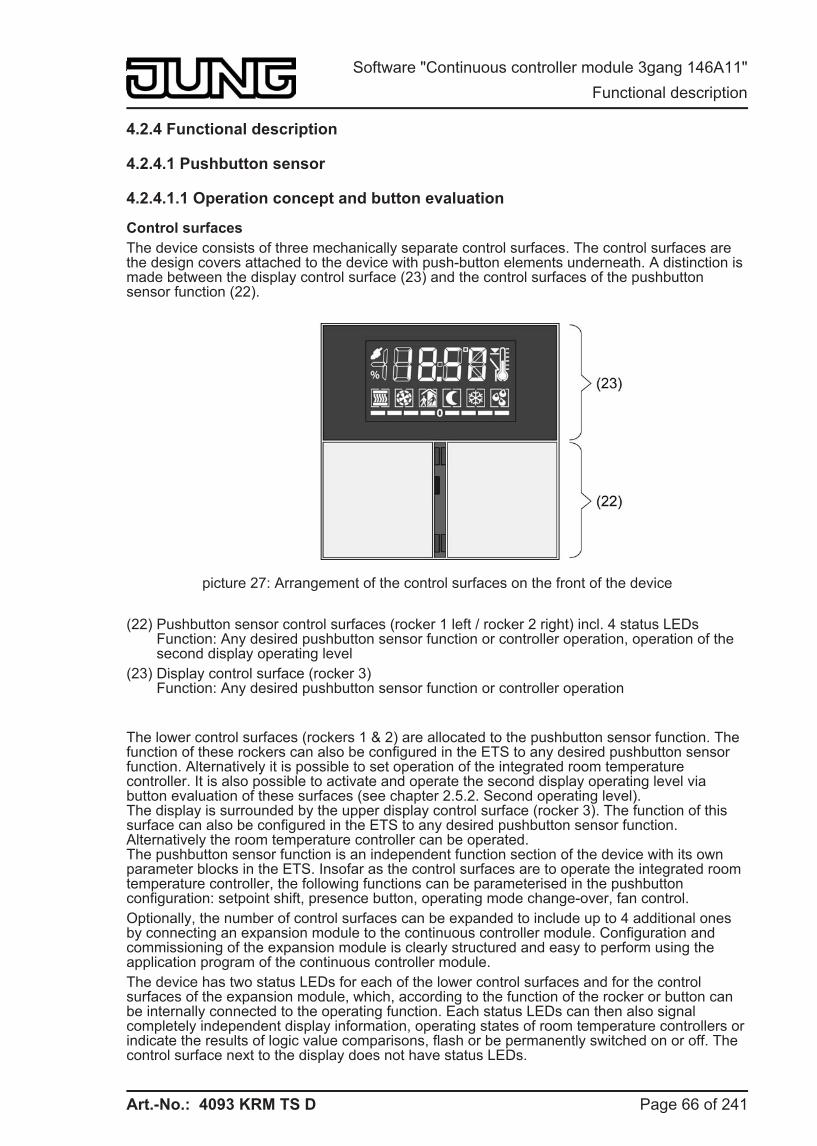
Art.-No.: 4093 KRM TS D
4.2.4 Functional description
4.2.4.1 Pushbutton sensor
4.2.4.1.1 Operation concept and button evaluation
Control surfaces The device consists of three mechanically separate control surfaces. The control surfaces are the design covers attached to the device with push-button elements underneath. A distinction is made between the display control surface (23) and the control surfaces of the pushbutton sensor function (22).
picture 27: Arrangement of the control surfaces on the front of the device
(22) Pushbutton sensor control surfaces (rocker 1 left / rocker 2 right) incl. 4 status LEDsFunction: Any desired pushbutton sensor function or controller operation, operation of the second display operating level
(23) Display control surface (rocker 3)Function: Any desired pushbutton sensor function or controller operation
The lower control surfaces (rockers 1 & 2) are allocated to the pushbutton sensor function. The function of these rockers can also be configured in the ETS to any desired pushbutton sensor function. Alternatively it is possible to set operation of the integrated room temperature controller. It is also possible to activate and operate the second display operating level via button evaluation of these surfaces (see chapter 2.5.2. Second operating level).The display is surrounded by the upper display control surface (rocker 3). The function of this surface can also be configured in the ETS to any desired pushbutton sensor function. Alternatively the room temperature controller can be operated.The pushbutton sensor function is an independent function section of the device with its own parameter blocks in the ETS. Insofar as the control surfaces are to operate the integrated room temperature controller, the following functions can be parameterised in the pushbutton configuration: setpoint shift, presence button, operating mode change-over, fan control. Optionally, the number of control surfaces can be expanded to include up to 4 additional ones by connecting an expansion module to the continuous controller module. Configuration and commissioning of the expansion module is clearly structured and easy to perform using the application program of the continuous controller module. The device has two status LEDs for each of the lower control surfaces and for the control surfaces of the expansion module, which, according to the function of the rocker or button can be internally connected to the operating function. Each status LEDs can then also signal completely independent display information, operating states of room temperature controllers or indicate the results of logic value comparisons, flash or be permanently switched on or off. The control surface next to the display does not have status LEDs.
Page 66 of 241
Software "Continuous controller module 3gang 146A11" Functional description
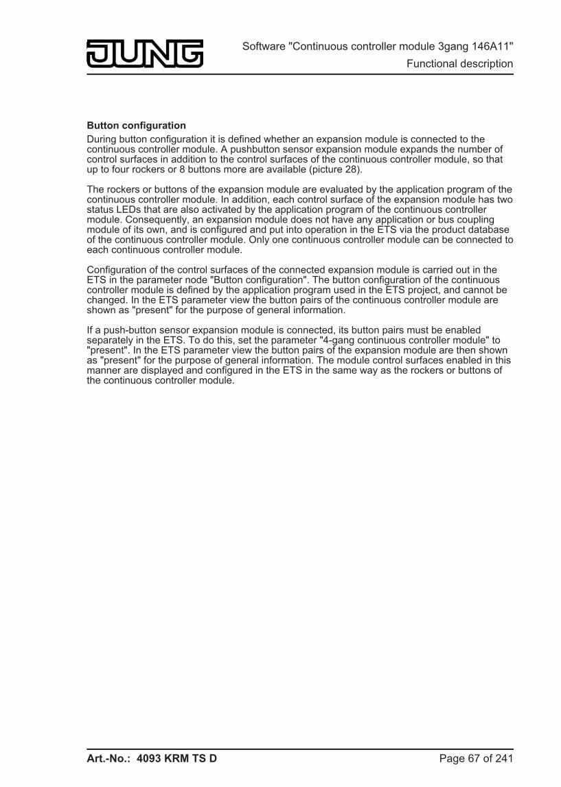
Art.-No.: 4093 KRM TS D
Button configuration During button configuration it is defined whether an expansion module is connected to the continuous controller module. A pushbutton sensor expansion module expands the number of control surfaces in addition to the control surfaces of the continuous controller module, so that up to four rockers or 8 buttons more are available (picture 28).
The rockers or buttons of the expansion module are evaluated by the application program of the continuous controller module. In addition, each control surface of the expansion module has two status LEDs that are also activated by the application program of the continuous controller module. Consequently, an expansion module does not have any application or bus coupling module of its own, and is configured and put into operation in the ETS via the product database of the continuous controller module. Only one continuous controller module can be connected to each continuous controller module.
Configuration of the control surfaces of the connected expansion module is carried out in the ETS in the parameter node "Button configuration". The button configuration of the continuous controller module is defined by the application program used in the ETS project, and cannot be changed. In the ETS parameter view the button pairs of the continuous controller module are shown as "present" for the purpose of general information.
If a push-button sensor expansion module is connected, its button pairs must be enabled separately in the ETS. To do this, set the parameter "4-gang continuous controller module" to "present". In the ETS parameter view the button pairs of the expansion module are then shown as "present" for the purpose of general information. The module control surfaces enabled in this manner are displayed and configured in the ETS in the same way as the rockers or buttons of the continuous controller module.
Page 67 of 241
Software "Continuous controller module 3gang 146A11" Functional description
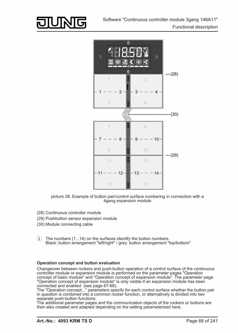
Art.-No.: 4093 KRM TS D
picture 28: Example of button pair/control surface numbering in connection with a4gang expansion module
(28) Continuous controller module (29) Pushbutton sensor expansion module (30) Module connecting cable
i The numbers (1...14) on the surfaces identify the button numbers.Black: button arrangement "left/right" / grey: button arrangement "top/bottom"
Operation concept and button evaluation Changeover between rockers and push-button operation of a control surface of the continuous controller module or expansion module is performed on the parameter pages "Operation concept of basic module" and "Operation concept of expansion module". The parameter page "Operation concept of expansion module" is only visible if an expansion module has been connected and enabled (see page 67-68).The "Operation concept..." parameters specify for each control surface whether the button pair in question is combined into a common rocker function, or alternatively is divided into two separate push-button functions.The additional parameter pages and the communication objects of the rockers or buttons are then also created and adapted depending on the setting parameterized here.
Page 68 of 241
Software "Continuous controller module 3gang 146A11" Functional description
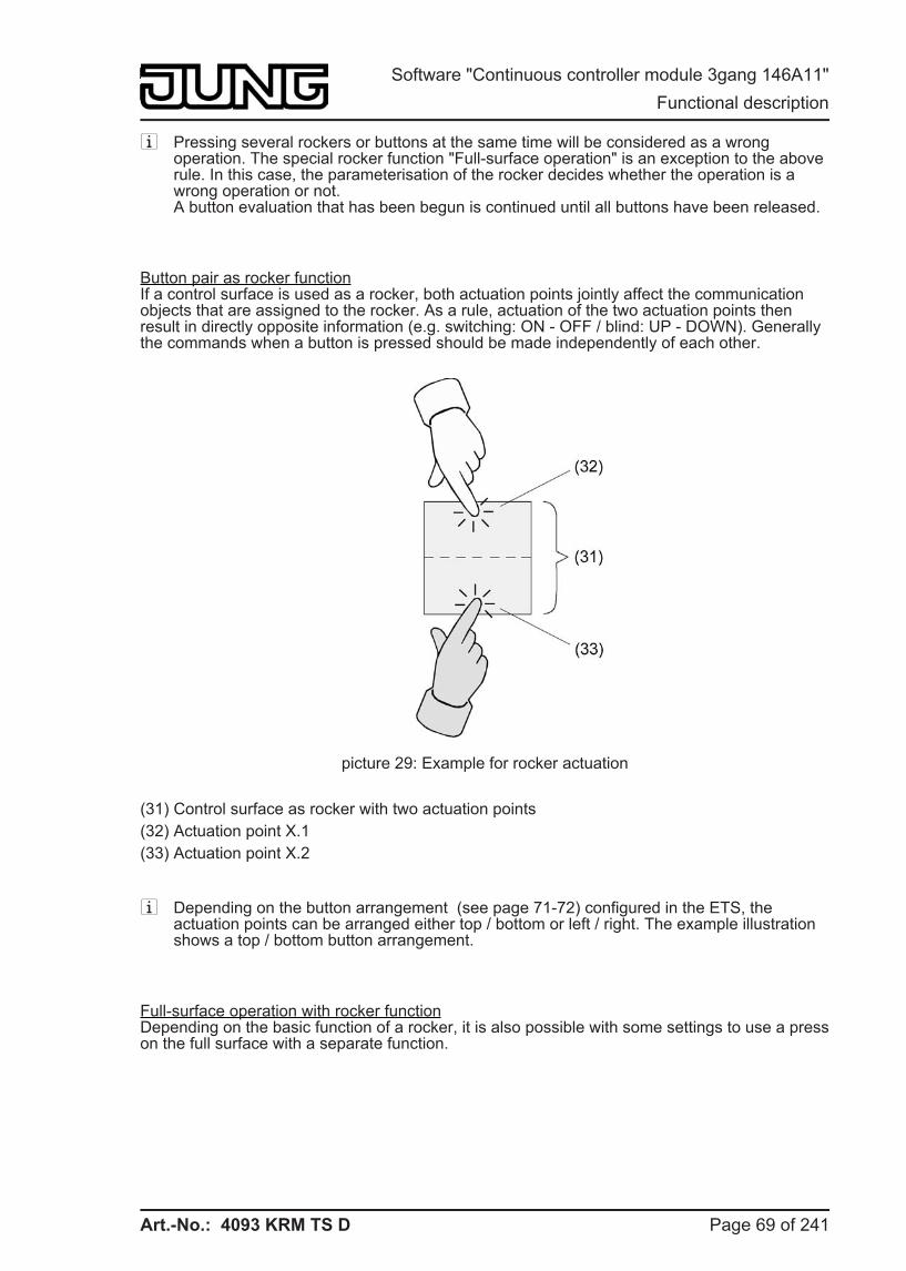
Art.-No.: 4093 KRM TS D
i Pressing several rockers or buttons at the same time will be considered as a wrong operation. The special rocker function "Full-surface operation" is an exception to the above rule. In this case, the parameterisation of the rocker decides whether the operation is a wrong operation or not.A button evaluation that has been begun is continued until all buttons have been released.
Button pair as rocker functionIf a control surface is used as a rocker, both actuation points jointly affect the communication objects that are assigned to the rocker. As a rule, actuation of the two actuation points then result in directly opposite information (e.g. switching: ON - OFF / blind: UP - DOWN). Generally the commands when a button is pressed should be made independently of each other.
picture 29: Example for rocker actuation
(31) Control surface as rocker with two actuation points (32) Actuation point X.1 (33) Actuation point X.2
i Depending on the button arrangement (see page 71-72) configured in the ETS, the actuation points can be arranged either top / bottom or left / right. The example illustration shows a top / bottom button arrangement.
Full-surface operation with rocker functionDepending on the basic function of a rocker, it is also possible with some settings to use a press on the full surface with a separate function.
Page 69 of 241
Software "Continuous controller module 3gang 146A11" Functional description
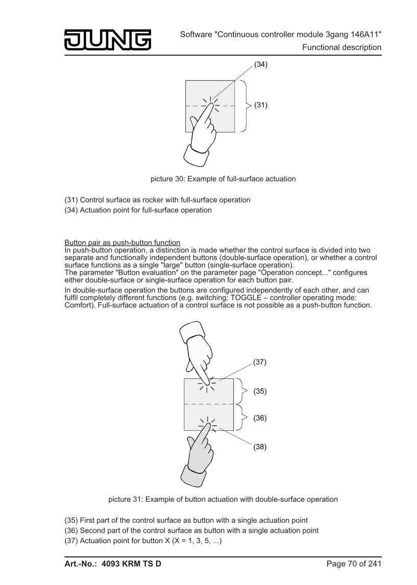
Art.-No.: 4093 KRM TS D
picture 30: Example of full-surface actuation
(31) Control surface as rocker with full-surface operation (34) Actuation point for full-surface operation
Button pair as push-button functionIn push-button operation, a distinction is made whether the control surface is divided into two separate and functionally independent buttons (double-surface operation), or whether a control surface functions as a single "large" button (single-surface operation).The parameter "Button evaluation" on the parameter page "Operation concept..." configures either double-surface or single-surface operation for each button pair. In double-surface operation the buttons are configured independently of each other, and can fulfil completely different functions (e.g. switching: TOGGLE – controller operating mode: Comfort). Full-surface actuation of a control surface is not possible as a push-button function.
picture 31: Example of button actuation with double-surface operation
(35) First part of the control surface as button with a single actuation point (36) Second part of the control surface as button with a single actuation point (37) Actuation point for button X (X = 1, 3, 5, ...)
Page 70 of 241
Software "Continuous controller module 3gang 146A11" Functional description
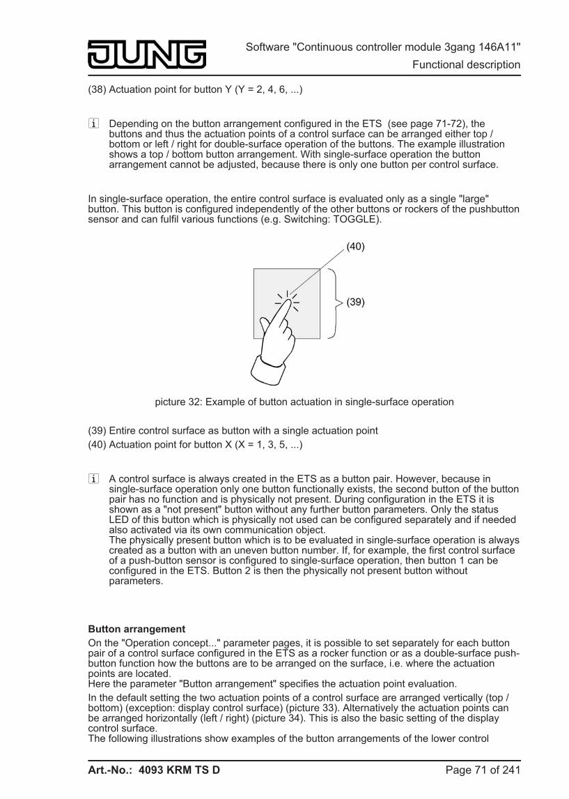
Art.-No.: 4093 KRM TS D
(38) Actuation point for button Y (Y = 2, 4, 6, ...)
i Depending on the button arrangement configured in the ETS (see page 71-72), the buttons and thus the actuation points of a control surface can be arranged either top / bottom or left / right for double-surface operation of the buttons. The example illustration shows a top / bottom button arrangement. With single-surface operation the button arrangement cannot be adjusted, because there is only one button per control surface.
In single-surface operation, the entire control surface is evaluated only as a single "large" button. This button is configured independently of the other buttons or rockers of the pushbutton sensor and can fulfil various functions (e.g. Switching: TOGGLE).
picture 32: Example of button actuation in single-surface operation
(39) Entire control surface as button with a single actuation point (40) Actuation point for button X (X = 1, 3, 5, ...)
i A control surface is always created in the ETS as a button pair. However, because in single-surface operation only one button functionally exists, the second button of the button pair has no function and is physically not present. During configuration in the ETS it is shown as a "not present" button without any further button parameters. Only the status LED of this button which is physically not used can be configured separately and if needed also activated via its own communication object.The physically present button which is to be evaluated in single-surface operation is always created as a button with an uneven button number. If, for example, the first control surface of a push-button sensor is configured to single-surface operation, then button 1 can be configured in the ETS. Button 2 is then the physically not present button without parameters.
Button arrangement On the "Operation concept..." parameter pages, it is possible to set separately for each button pair of a control surface configured in the ETS as a rocker function or as a double-surface push-button function how the buttons are to be arranged on the surface, i.e. where the actuation points are located.Here the parameter "Button arrangement" specifies the actuation point evaluation. In the default setting the two actuation points of a control surface are arranged vertically (top / bottom) (exception: display control surface) (picture 33). Alternatively the actuation points can be arranged horizontally (left / right) (picture 34). This is also the basic setting of the display control surface.The following illustrations show examples of the button arrangements of the lower control
Page 71 of 241
Software "Continuous controller module 3gang 146A11" Functional description
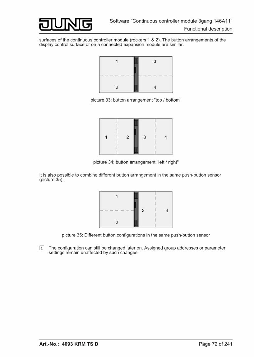
Art.-No.: 4093 KRM TS D
surfaces of the continuous controller module (rockers 1 & 2). The button arrangements of the display control surface or on a connected expansion module are similar.
picture 33: button arrangement "top / bottom"
picture 34: button arrangement "left / right"
It is also possible to combine different button arrangement in the same push-button sensor (picture 35).
picture 35: Different button configurations in the same push-button sensor
i The configuration can still be changed later on. Assigned group addresses or parameter settings remain unaffected by such changes.
Page 72 of 241
Software "Continuous controller module 3gang 146A11" Functional description
Art.-No.: 4093 KRM TS D
4.2.4.1.2 "Switching" function For each rocker or each button with the function set to "Switching", the ETS indicates a 1-bit communication object. The parameters of the rocker or button permit fixing the value this object is to adopt on pressing and / or on releasing (ON, OFF, TOGGLE – toggling of the object value). No distinction is made between a brief or long press.
The status LEDs can be configured independently (see chapter 4.2.4.1.13. Status LED).
Page 73 of 241
Software "Continuous controller module 3gang 146A11" Functional description
Art.-No.: 4093 KRM TS D
4.2.4.1.3 "Dimming" function For each rocker or each button with the function set to "Dimming", the ETS indicates a 1-bit object and a 4-bit object. Generally, the pushbutton sensor transmits a switching telegram after a brief press and a dimming telegram after a long press. In the standard parameterisation, the pushbutton sensor transmits a telegram for stopping the dimming action after a long press. The time needed by the pushbutton sensor to detect an actuation as a long actuation can be set in the parameters.
The status LEDs can be configured independently (see chapter 4.2.4.1.13. Status LED).
Single-surface and double-surface operation in the dimming functionAs a rocker, the device is preprogrammed for double-surface actuation for the dimming function. This means that the pushbutton sensor transmits a telegram for switch-on after a brief press and a telegram for increasing the brightness after a long press of the left button. Similarly, the pushbutton sensor transmits a telegram for switch-off after a brief press and a telegram for reducing the brightness after a long press on the right button.As a button, the device is preprogrammed for single-surface actuation for the dimming function. In this mode, the pushbutton sensor transmits on each brief press ON and OFF telegrams in an alternating pattern ("TOGGLE"). After a long press, the pushbutton sensor transmits "brighter" and "darker" telegrams in an alternating pattern.The parameter "Command on pressing the button" or Command on pressing the rocker" on the parameter pages of the buttons or rockers defines the single-surface or double-surface operation principle for the dimming function.For the rocker or push-button function, the command issued on pressing the button or rocker can basically be selected at the user's discretion.
Advanced parametersFor the dimming function, the pushbutton sensor can be programmed with advanced parameters which are hidden in the standard view for greater clarity. If necessary, these advanced parameters can be activated and thus be made visible.The advanced parameters can be used to determine whether the pushbutton sensor is to cover the full adjusting range of the actuator with one dimming telegram continuously ("Increase brightness by 100%", "Reduce brightness by 100%) or whether the dimming range is to be divided into several small levels (50%, 25%, 12.5%, 6%, 3%, 1.5%).In the continuous dimming mode (100%), the pushbutton sensor transmits a telegram only at the beginning of the long press to start the dimming process and generally a stop telegram after the end of the press. For dimming in small levels it may be useful if the pushbutton sensor repeats the dimming telegram in case of a sustained press for a presettable time (parameter "Telegram repetition"). The stop telegram after the end of the press is then not needed.When the parameters are hidden ("Advanced parameters = deactivated"), the dimming range is set to 100 %, the stop telegram is activated and the telegram repetition is deactivated.
Full-surface operationWhen a rocker is used for dimming, the pushbutton sensor needs some time at the beginning of each operation in order to distinguish between a short and a long operation. When the full-surface operation is enabled in the ETS, the pushbutton sensor can make use of this time span to evaluate the otherwise invalid simultaneous actuation of both actuation points.The pushbutton sensor detects a full-surface operation of a rocker if a control surface is depressed over a large area so that both buttons of the rocker are actuated.When the pushbutton sensor has detected a valid full-surface actuation, the operation LED flashes quickly at a frequency of about 8 Hz for the duration of such actuation. Full-surface operation must have been detected before the first telegram has been transmitted by the dimming function (switching or dimming). If this is not so, even a full-surface operation will be interpreted as a wrong operation and not be executed.Full-surface actuation is independent. It has a communication object of its own an can optionally be used for switching (ON, OFF, TOGGLE – toggling of the object value) or for scene recall without or with storage function. In the last case, a press on the full surface causes a scene to be recalled in less than a second. If the pushbutton sensor is to send the telegram for storing a scene, full-surface actuation must be maintained for more than five seconds. If full-surface actuation ends between the first and the fifth second, the pushbutton sensor will not send any
Page 74 of 241
Software "Continuous controller module 3gang 146A11" Functional description
Art.-No.: 4093 KRM TS D
telegrams. If the status LEDs of the rocker are used as "button-press displays", they will light up for three seconds during transmission of the storage telegram.
i Full-surface actuation cannot be configured in the push-button functions.
Page 75 of 241
Software "Continuous controller module 3gang 146A11" Functional description
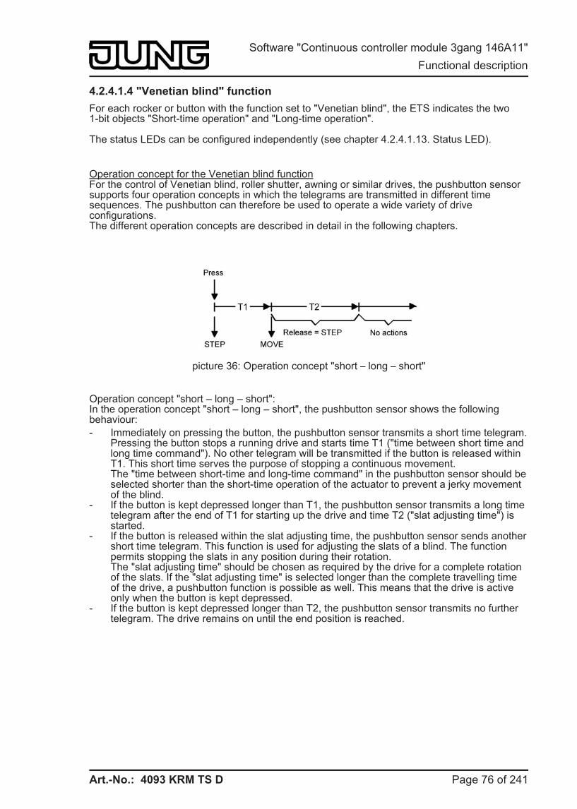
Art.-No.: 4093 KRM TS D
4.2.4.1.4 "Venetian blind" function For each rocker or button with the function set to "Venetian blind", the ETS indicates the two 1-bit objects "Short-time operation" and "Long-time operation".
The status LEDs can be configured independently (see chapter 4.2.4.1.13. Status LED).
Operation concept for the Venetian blind functionFor the control of Venetian blind, roller shutter, awning or similar drives, the pushbutton sensor supports four operation concepts in which the telegrams are transmitted in different time sequences. The pushbutton can therefore be used to operate a wide variety of drive configurations.The different operation concepts are described in detail in the following chapters.
picture 36: Operation concept "short – long – short"
Operation concept "short – long – short":In the operation concept "short – long – short", the pushbutton sensor shows the following behaviour: - Immediately on pressing the button, the pushbutton sensor transmits a short time telegram.
Pressing the button stops a running drive and starts time T1 ("time between short time and long time command"). No other telegram will be transmitted if the button is released within T1. This short time serves the purpose of stopping a continuous movement.The "time between short-time and long-time command" in the pushbutton sensor should be selected shorter than the short-time operation of the actuator to prevent a jerky movement of the blind.
- If the button is kept depressed longer than T1, the pushbutton sensor transmits a long time telegram after the end of T1 for starting up the drive and time T2 ("slat adjusting time") is started.
- If the button is released within the slat adjusting time, the pushbutton sensor sends another short time telegram. This function is used for adjusting the slats of a blind. The function permits stopping the slats in any position during their rotation.The "slat adjusting time" should be chosen as required by the drive for a complete rotation of the slats. If the "slat adjusting time" is selected longer than the complete travelling time of the drive, a pushbutton function is possible as well. This means that the drive is active only when the button is kept depressed.
- If the button is kept depressed longer than T2, the pushbutton sensor transmits no further telegram. The drive remains on until the end position is reached.
Page 76 of 241
Software "Continuous controller module 3gang 146A11" Functional description
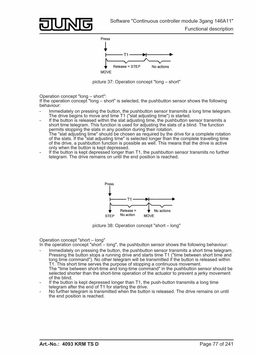
Art.-No.: 4093 KRM TS D
picture 37: Operation concept "long – short"
Operation concept "long – short":If the operation concept "long – short" is selected, the pushbutton sensor shows the following behaviour: - Immediately on pressing the button, the pushbutton sensor transmits a long time telegram.
The drive begins to move and time T1 ("slat adjusting time") is started. - If the button is released within the slat adjusting time, the pushbutton sensor transmits a
short time telegram. This function is used for adjusting the slats of a blind. The function permits stopping the slats in any position during their rotation.The "slat adjusting time" should be chosen as required by the drive for a complete rotation of the slats. If the "slat adjusting time" is selected longer than the complete travelling time of the drive, a pushbutton function is possible as well. This means that the drive is active only when the button is kept depressed.
- If the button is kept depressed longer than T1, the pushbutton sensor transmits no further telegram. The drive remains on until the end position is reached.
picture 38: Operation concept "short – long"
Operation concept "short – long"In the operation concept "short – long", the pushbutton sensor shows the following behaviour: - Immediately on pressing the button, the pushbutton sensor transmits a short time telegram.
Pressing the button stops a running drive and starts time T1 ("time between short time and long time command"). No other telegram will be transmitted if the button is released within T1. This short time serves the purpose of stopping a continuous movement.The "time between short-time and long-time command" in the pushbutton sensor should be selected shorter than the short-time operation of the actuator to prevent a jerky movement of the blind.
- If the button is kept depressed longer than T1, the push-button transmits a long time telegram after the end of T1 for starting the drive.
- No further telegram is transmitted when the button is released. The drive remains on until the end position is reached.
Page 77 of 241
Software "Continuous controller module 3gang 146A11" Functional description
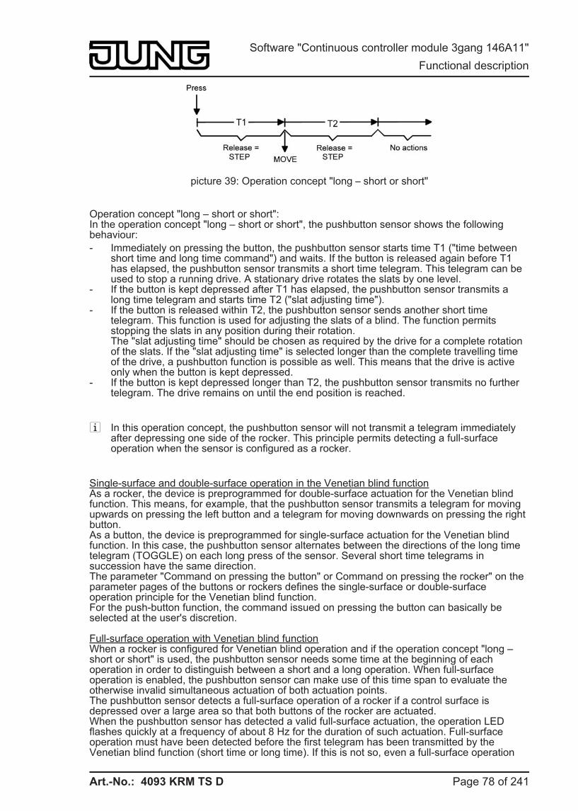
Art.-No.: 4093 KRM TS D
picture 39: Operation concept "long – short or short"
Operation concept "long – short or short":In the operation concept "long – short or short", the pushbutton sensor shows the following behaviour: - Immediately on pressing the button, the pushbutton sensor starts time T1 ("time between
short time and long time command") and waits. If the button is released again before T1 has elapsed, the pushbutton sensor transmits a short time telegram. This telegram can be used to stop a running drive. A stationary drive rotates the slats by one level.
- If the button is kept depressed after T1 has elapsed, the pushbutton sensor transmits a long time telegram and starts time T2 ("slat adjusting time").
- If the button is released within T2, the pushbutton sensor sends another short time telegram. This function is used for adjusting the slats of a blind. The function permits stopping the slats in any position during their rotation.The "slat adjusting time" should be chosen as required by the drive for a complete rotation of the slats. If the "slat adjusting time" is selected longer than the complete travelling time of the drive, a pushbutton function is possible as well. This means that the drive is active only when the button is kept depressed.
- If the button is kept depressed longer than T2, the pushbutton sensor transmits no further telegram. The drive remains on until the end position is reached.
i In this operation concept, the pushbutton sensor will not transmit a telegram immediately after depressing one side of the rocker. This principle permits detecting a full-surface operation when the sensor is configured as a rocker.
Single-surface and double-surface operation in the Venetian blind functionAs a rocker, the device is preprogrammed for double-surface actuation for the Venetian blind function. This means, for example, that the pushbutton sensor transmits a telegram for moving upwards on pressing the left button and a telegram for moving downwards on pressing the right button.As a button, the device is preprogrammed for single-surface actuation for the Venetian blind function. In this case, the pushbutton sensor alternates between the directions of the long time telegram (TOGGLE) on each long press of the sensor. Several short time telegrams in succession have the same direction.The parameter "Command on pressing the button" or Command on pressing the rocker" on the parameter pages of the buttons or rockers defines the single-surface or double-surface operation principle for the Venetian blind function.For the push-button function, the command issued on pressing the button can basically be selected at the user's discretion.
Full-surface operation with Venetian blind functionWhen a rocker is configured for Venetian blind operation and if the operation concept "long – short or short" is used, the pushbutton sensor needs some time at the beginning of each operation in order to distinguish between a short and a long operation. When full-surface operation is enabled, the pushbutton sensor can make use of this time span to evaluate the otherwise invalid simultaneous actuation of both actuation points.The pushbutton sensor detects a full-surface operation of a rocker if a control surface is depressed over a large area so that both buttons of the rocker are actuated.When the pushbutton sensor has detected a valid full-surface actuation, the operation LED flashes quickly at a frequency of about 8 Hz for the duration of such actuation. Full-surface operation must have been detected before the first telegram has been transmitted by the Venetian blind function (short time or long time). If this is not so, even a full-surface operation
Page 78 of 241
Software "Continuous controller module 3gang 146A11" Functional description
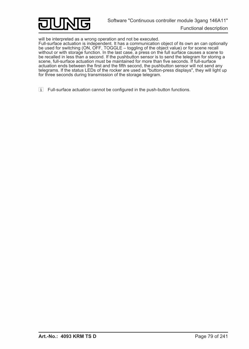
Art.-No.: 4093 KRM TS D
will be interpreted as a wrong operation and not be executed.Full-surface actuation is independent. It has a communication object of its own an can optionally be used for switching (ON, OFF, TOGGLE – toggling of the object value) or for scene recall without or with storage function. In the last case, a press on the full surface causes a scene to be recalled in less than a second. If the pushbutton sensor is to send the telegram for storing a scene, full-surface actuation must be maintained for more than five seconds. If full-surface actuation ends between the first and the fifth second, the pushbutton sensor will not send any telegrams. If the status LEDs of the rocker are used as "button-press displays", they will light up for three seconds during transmission of the storage telegram.
i Full-surface actuation cannot be configured in the push-button functions.
Page 79 of 241
Software "Continuous controller module 3gang 146A11" Functional description
Art.-No.: 4093 KRM TS D
4.2.4.1.5 Value transmitter function For each rocker or button with the function set to "1-byte value transmitter" or "2-byte value transmitter" the ETS indicates a corresponding object. On the press of a button, the configured value or the value last stored internally by a value change (see below) will be transmitted to the bus. In case of the rocker function, different values can be configured or varied for both buttons.
The status LEDs can be configured independently (see chapter 4.2.4.1.13. Status LED).
Value rangesThe "Function" parameter determines the value range used by the pushbutton.As a 1-byte value encoder, the pushbutton sensor can optionally transmit integers from 0 … 255 or relative values within a range of 0 … 100 % (e.g. as dimming value transmitter).
As a 2-byte value encoder, the pushbutton sensor can optionally transmit integers from 0 … 65535, temperature values within a range of 0 … 40 °C or brightness values from 0 … 1500 lux. For each of these ranges, the value that can be transmitted to the bus for each operation of a rocker or button is configurable.
Adjustment by means of long button-pressIf the value adjustment feature has been enabled in the ETS, the button must be kept depressed for more than 5 seconds in order to vary the current value of the value transmitter. The value adjustment function continues to be active until the button is released again. In a value adjustment, the pushbutton sensor distinguishes between the following options... - The "Starting value in case of value adjustment" parameter defines the original starting
value for the adjustment. Adjustment can begin from the value configured in the ETS, from the final value of the last adjustment cycle or from the current value of the communication object, with the last option not being available for the temperature and brightness value transmitter.
- The parameter "Direction of value adjustment" defines whether the values will always be increased ("upwards"), always reduced ("downwards") or alternately increased and reduced ("toggling").
- For the value transmitters 0 … 255, 0 … 100 % and 0 … 65535, the "level size" by which the current value is to be changed during the value adjustment can be specified. In case of the temperature and the brightness value transmitter, the level size specifications (1 °C and 50 lux) are fixed.
- The parameter "Time between two telegrams" can be used in connection with the step size to define the time required to cycle through the full respective value range. This value defines the time span between two value transmissions.
- If, during the value adjustment, the pushbutton sensor detects that the preset level size would result in the limits being exceeded with the next telegram, it adapts the level size once in such a way that the respective limiting value is transmitted together with last telegram. Depending on the setting of the parameter "Value adjustment with overflow", the pushbutton sensor stops the adjustment at this instance or inserts a pause consisting of two levels and then continues the adjustment beginning with the other limiting value.
Page 80 of 241
Software "Continuous controller module 3gang 146A11" Functional description
Art.-No.: 4093 KRM TS D
Type Function Lower numerical limit Upper numerical limit 1-byte value transmitter 0...255 0 255 1-byte value transmitter 0...100 % 0 % (value = 0) 100 % (value = 255) 2-byte value transmitter 0...65535 0 65535 2-byte value transmitter Temperature value 0 °C 40 °C 2-byte value transmitter Brightness value 0 lux 1,500 lux
Table 1: Value range limits for the different value transmitters
i During a value adjustment, the newly adjusted values are only in the volatile RAM memory of the pushbutton sensor. Therefore, the stored values are replaced by the preset values programmed in the ETS when a reset of the pushbutton sensor occurs (bus voltage failure or ETS programming).
i In the functions "Always OFF", "Always ON" and "Button-press display", the status LED indicates an active value change when the value of the corresponding button is changed. The status LED is then switched off and will then light up for approx. 250 ms whenever a new value is transmitted.
i With the 1-byte value encoder in the "Value transmitter 0…100 %" function, the level size of the adjustment will also be indicated in "%". If the starting value of the communication object is used, it may happen in this case during value adjustment that the value last received via the object must be rounded and adapted before a new value can be calculated on the basis of the level size and transmitted. Due to the computation procedure used, the new calculation of the value may be slightly inaccurate.
Value adjustment examples
Parameterisation example:
- Value transmitter 1-byte (all other value transmitters identical) - Function = value transmitter 0…255 - Value configured in the ETS (0...255) = 227 - Level size (1...10) = 5 - Start on value adjustment = same as configured value - Direction of value adjustment = change-over (alternating) - Time between two telegrams = 0.5 s
Example 1: Value adjustment with overflow? = No
picture 40: Example of value adjustment without value range overflow
Page 81 of 241
Software "Continuous controller module 3gang 146A11" Functional description
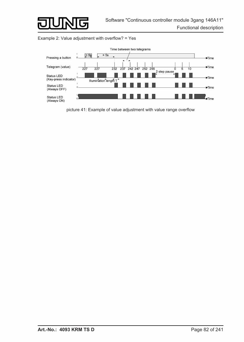
Art.-No.: 4093 KRM TS D
Example 2: Value adjustment with overflow? = Yes
picture 41: Example of value adjustment with value range overflow
Page 82 of 241
Software "Continuous controller module 3gang 146A11" Functional description
Art.-No.: 4093 KRM TS D
4.2.4.1.6 "Scene extension" function
For each rocker or button with the function set to "scene extension unit" the ETS indicates the "Function" parameter which distinguishes between the following settings... - "Scene extension without storage function" - "Scene extension with storage function", - "Recall of internal scene without storage function", - "Recall of internal scene extension with storage function".
In the scene extension function, the pushbutton sensor transmits a preset scene number (1…64) via a separate communication object to the bus after a button-press. This feature permits recalling scenes stored in other devices and also storing them, if the storage function is used.The recall of an internal scene does not result in a telegram being transmitted to the bus. For this reason, the corresponding communication object is missing. This function can rather be used to recall – and with the storage function also to store – the up to 8 scenes stored internally in the device.
In the setting "... without storage function", a button-press triggers the simple recall of a scene. If the status LED is configured as button-press display, it will be switched on for the configured ON time. A long button-press has no further or additional effect.In the setting "... with storage function", the pushbutton sensor monitors the length of the operation. A button-press of less than a second results in a simple recall of the scene as mentioned above. If the status LED is configured as button-press display, it will be switched on for the configured ON time.After a button-press of more than five seconds, the pushbutton sensor generates a storage instruction. In the scene extension function, a storage telegram is in this case transmitted to the bus. If configured for the recall of an internal scene, the sensor will store the internal scene.An operation lasting between one and five seconds will be discarded as invalid.
The parameter "Scene number" specifies which of the maximum of 8 internal or 64 external scenes is to be used after a button-press. In case of the rocker function, two different scene numbers can be assigned.
The status LEDs can be configured independently (see chapter 4.2.4.1.13. Status LED).
Page 83 of 241
Software "Continuous controller module 3gang 146A11" Functional description
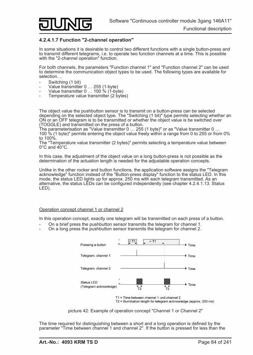
Art.-No.: 4093 KRM TS D
4.2.4.1.7 Function "2-channel operation"
In some situations it is desirable to control two different functions with a single button-press and to transmit different telegrams, i.e. to operate two function channels at a time. This is possible with the "2-channel operation" function.
For both channels, the parameters "Function channel 1" and "Function channel 2" can be used to determine the communication object types to be used. The following types are available for selection… - Switching (1 bit) - Value transmitter 0 … 255 (1-byte) - Value transmitter 0 … 100 % (1-byte) - Temperature value transmitter (2 bytes)
The object value the pushbutton sensor is to transmit on a button-press can be selected depending on the selected object type. The "Switching (1 bit)" type permits selecting whether an ON or an OFF telegram is to be transmitted or whether the object value is be switched over (TOGGLE) and transmitted on the press of a button.The parameterisation as "Value transmitter 0 … 255 (1 byte)" or as "Value transmitter 0 … 100 % (1 byte)" permits entering the object value freely within a range from 0 to 255 or from 0% to 100%.The "Temperature value transmitter (2 bytes)" permits selecting a temperature value between 0°C and 40°C.
In this case, the adjustment of the object value on a long button-press is not possible as the determination of the actuation length is needed for the adjustable operation concepts.
Unlike in the other rocker and button functions, the application software assigns the "Telegram acknowledge" function instead of the "Button-press display" function to the status LED. In this mode, the status LED lights up for approx. 250 ms with each telegram transmitted. As an alternative, the status LEDs can be configured independently (see chapter 4.2.4.1.13. Status LED).
Operation concept channel 1 or channel 2
In this operation concept, exactly one telegram will be transmitted on each press of a button. - On a brief press the pushbutton sensor transmits the telegram for channel 1. - On a long press the pushbutton sensor transmits the telegram for channel 2.
picture 42: Example of operation concept "Channel 1 or Channel 2"
The time required for distinguishing between a short and a long operation is defined by the parameter "Time between channel 1 and channel 2". If the button is pressed for less than the
Page 84 of 241
Software "Continuous controller module 3gang 146A11" Functional description
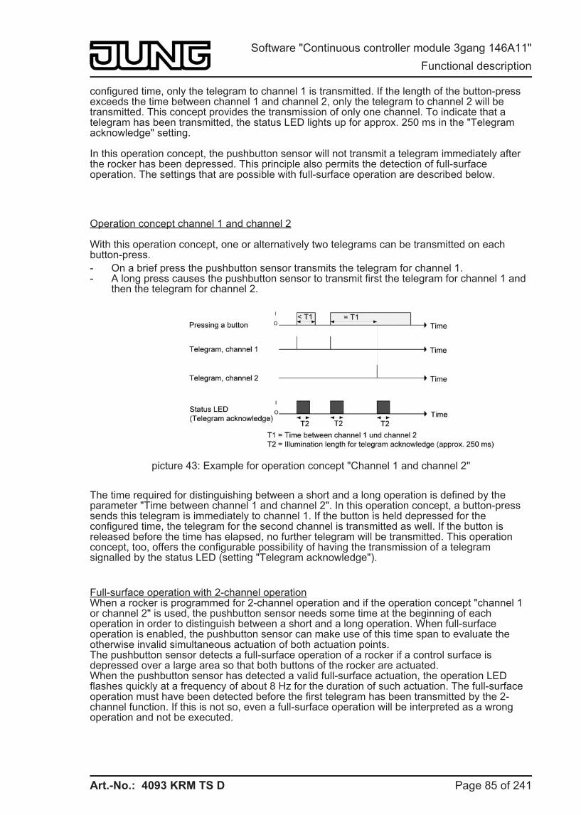
Art.-No.: 4093 KRM TS D
configured time, only the telegram to channel 1 is transmitted. If the length of the button-press exceeds the time between channel 1 and channel 2, only the telegram to channel 2 will be transmitted. This concept provides the transmission of only one channel. To indicate that a telegram has been transmitted, the status LED lights up for approx. 250 ms in the "Telegram acknowledge" setting.
In this operation concept, the pushbutton sensor will not transmit a telegram immediately after the rocker has been depressed. This principle also permits the detection of full-surface operation. The settings that are possible with full-surface operation are described below.
Operation concept channel 1 and channel 2
With this operation concept, one or alternatively two telegrams can be transmitted on each button-press. - On a brief press the pushbutton sensor transmits the telegram for channel 1. - A long press causes the pushbutton sensor to transmit first the telegram for channel 1 and
then the telegram for channel 2.
picture 43: Example for operation concept "Channel 1 and channel 2"
The time required for distinguishing between a short and a long operation is defined by the parameter "Time between channel 1 and channel 2". In this operation concept, a button-press sends this telegram is immediately to channel 1. If the button is held depressed for the configured time, the telegram for the second channel is transmitted as well. If the button is released before the time has elapsed, no further telegram will be transmitted. This operation concept, too, offers the configurable possibility of having the transmission of a telegram signalled by the status LED (setting "Telegram acknowledge").
Full-surface operation with 2-channel operationWhen a rocker is programmed for 2-channel operation and if the operation concept "channel 1 or channel 2" is used, the pushbutton sensor needs some time at the beginning of each operation in order to distinguish between a short and a long operation. When full-surface operation is enabled, the pushbutton sensor can make use of this time span to evaluate the otherwise invalid simultaneous actuation of both actuation points.The pushbutton sensor detects a full-surface operation of a rocker if a control surface is depressed over a large area so that both buttons of the rocker are actuated.When the pushbutton sensor has detected a valid full-surface actuation, the operation LED flashes quickly at a frequency of about 8 Hz for the duration of such actuation. The full-surface operation must have been detected before the first telegram has been transmitted by the 2-channel function. If this is not so, even a full-surface operation will be interpreted as a wrong operation and not be executed.
Page 85 of 241
Software "Continuous controller module 3gang 146A11" Functional description
Art.-No.: 4093 KRM TS D
4.2.4.1.8 "Controller extension" function The controller extension function can be activated to control a KNX/EIB room temperature controller. The controller extension function is enabled using the "Controller extension" setting of the parameter "Room temperature controller function" in the "Room temperature controller" parameter node.The controller extension is operated using the push-button functions of the device. In this way, it is possible to completely control a room temperature controller by changing the operating mode, by predefining the presence situation or by readjusting the setpoint shift. For this purpose, the buttons of the pushbutton sensor selected as extension operation buttons must be configured for the "Controller extension" function.
The operating function of the controller extension is described in detail in the chapter "Room temperature controller extension" (see chapter 4.2.4.1.13. Status LED). i It should be noted that an extension operation is possible with a button configuration. The
controller extension function must be enabled in the "Room temperature controller" parameter node. In all other cases, the controller extension function is not operational in the "Pushbutton sensor" function section.
Page 86 of 241
Software "Continuous controller module 3gang 146A11" Functional description
Art.-No.: 4093 KRM TS D
4.2.4.1.9 "Fan control" function The room temperature controller can be supplemented with a fan controller. This makes it possible to control the fan from heating and cooling systems operated by circulating air, such as fan coil units (FanCoil units), depending on the command value calculated in the controller or using manual operation.The fan controller distinguishes between Automatic and Manual operation. It is possible to change-over the fan operating mode and the fan operation using a button on the device, which is configured to the "Fan controller" function.
The operating function of the fan controller is described in detail in the chapter "Room temperature controller" (see chapter 4.2.4.2.8. Fan controller). In the case of manual operation the symbol Ü is shown on the display of the device. i It should be noted that fan control is only possible with a button configuration. The fan
controller must be enabled in the "Room temperature -> Controller general" parameter node. Otherwise the fan control in the "Pushbutton sensor" function section has no function.
Page 87 of 241
Software "Continuous controller module 3gang 146A11" Functional description
Art.-No.: 4093 KRM TS D
4.2.4.1.10 "Controller operating mode" function The "Controller operating mode" push-button function can be used to control the internal room temperature controller. If this push-button function is used, it is possible to change over the operating mode by pressing the button. In the controller operating mode, a distinction is made between two functions, specified by the "Button function" parameter. On the one hand, the operating mode (Comfort, Standby, Night, Frost/heat protection) can be changed over and influenced ("Operating mode change-over" setting). On the other hand it is possible to activate the Presence function ("Presence button" setting). The Presence function allows activation of Comfort mode or a comfort extension on the internal controller.
The operating mode change-over and the presence function are described in detail in the chapter "Operating mode change-over" (see chapter 4.2.4.2.4. Operating mode change-over). i It should be noted that the "Controller operating mode" function is only possible with a
button configuration. The room temperature controller function must be enabled using the parameter of the same name in the "Room temperature control" parameter node. Otherwise the operation of the controller operating mode in the "Pushbutton sensor" function section has no function. In controller extension operation, the "Controller operating mode" push-button function also has no function. Here, the "Controller extension" push-button function can be used, allowing setting of the operating mode.
Page 88 of 241
Software "Continuous controller module 3gang 146A11" Functional description
Art.-No.: 4093 KRM TS D
4.2.4.1.11 "Setpoint shift" function The "Setpoint shift" push-button function can be used to control the internal room temperature controller. If this push-button function is used, it is possible to shift the setpoint temperature of the controller in a positive or negative direction by pressing the button.
The basic setpoint shift is described in detail in the chapter "Temperature setpoints" (see chapter 4.2.4.2.5. Temperature setpoints). i It should be noted that the "Setpoint shift" function is only possible with a button
configuration. The room temperature controller function must be enabled using the parameter of the same name in the "Room temperature control" parameter node. Otherwise the operation of the setpoint shift in the "Pushbutton sensor" function section has no function. In controller extension operation, the "Setpoint shift" push-button function also has no function. Here, the "Controller extension" push-button function can be used, allowing a setpoint shift.
i When a function button for the setpoint shift is pressed, the current shift is displayed on the display by means of a line graphic. The indication of the basic setpoint shift makes a distinction between the positive "0 - - - -" or negative "- - - - 0" direction. A bar corresponds to shifting by one level value. The value of a level can be parameterised in the ETS. If no shift is active, only "0" is displayed.The shifted temperature value is instantly accepted as the new setpoint when a function button is pressed.Optionally the setpoint of the respective current operating mode can be shown automatically in the display if a setpoint shift is performed using the buttons of the device. The setpoint temperature is then indicated temporarily for 5 s in °C or °F, and overwrites the normal display (time, actual temperature, etc.). The setpoint display in the case of a setpoint shift can be activated by setting the "Show temporary setpoint in display when setpoint shift?" parameter. to "Yes". With the setting "No" the temporary indication is inactive, meaning that in case of a setpoint shift only the line graphic is activated, but the temperature value is not also displayed automatically.
Page 89 of 241
Software "Continuous controller module 3gang 146A11" Functional description
Art.-No.: 4093 KRM TS D
4.2.4.1.12 "Change in the display reading" function Up to four pieces of display information (time, actual temperature, setpoint temperature, outdoor temperature) can be shown on the LC display of the device (see chapter 4.2.4.5.1. Displayed information). The individual pieces of information are shown separately in the numeric display. If more than one piece of display information is configured in the ETS in the parameter node "Display", then the display must be switched over during operation.In addition to the cyclical change, the indication can also be switched by pressing a button on the device. To do this it is possible to configure a button for the "Change in the display reading" function. This configuration is performed in the parameter block of the respective button. This function can be configured for any desired buttons on the continuous controller module and optionally also for buttons on the expansion module.
When a button is pressed, depending on the "On pressing a button" parameter either the next or the previous display information is called up in accordance with the cyclical change. With this setting the display information specified according to the configuration in the "Display" parameter node can be switched directly.Alternatively it is also possible to call up a particular piece of information immediately independently of the display information of the cyclical change (e.g. push-button function "Call up time"). It is not assumed here that the indication called up in this manner is in fact integrated into the cyclical change. After a piece of information is called up by pressing a button, the indication is retained until the time for the cyclical change has elapsed.
i In the parameter node "Display", it is also possible to set that no information is displayed using the parameter "Number of pieces of display information". In this case the normal depiction of the display is dark (only the symbols of the room temperature controller are displayed). It is then only possible as necessary to call up individual display information by pressing a button using the push-button function "Change in the display reading". The indication called up in this manner then remains temporarily visible in the display depending on the time configured for the cyclical change.
i The time for the cyclical change of the display can be set in the ETS in the parameter node "Display".
Page 90 of 241
Software "Continuous controller module 3gang 146A11" Functional description
Art.-No.: 4093 KRM TS D
4.2.4.1.13 Status LED Each control surface of the device (basic module and expansion module) has two status LEDs. The only exception here is the display control surface, which does not have its own status LED. Depending on the configuration of the rockers or buttons, the possible LED functions available differ slightly.
Each status LED distinguishes the following options... - Always OFF, - Always ON, - Activation via separate LED object, - Comparator without sign (1 byte), - Comparator with sign (1 byte). These setting options are generally available even if the buttons have no function assigned.
If a function has been assigned to the rocker or button, the ETS displays moreover the option… - Button-press display.
In the function "2-channel operation", this setting is replaced by… - Telegram acknowledgment.
If the rocker or the button is used for switching or dimming or to control the fan or setpoint shift, the following functions can additionally be set... - Status indication, - inverted status indication.
In addition, the status LEDs may possess the following option, if a controller extension, a fan controller, a controller operating mode change-over, a setpoint shift or a change in the display reading is not configured ... - Operating mode indication (KNX controller).
If a button is used for the operation of a controller extension and the "Presence button" function is used, then the following option can additionally be set... - Push-button function active / inactive indication
i Besides the functions that can be set separately for each status LED, all status LEDs are also used together with the operation LED for alarm message. If this is active, all LEDs of the device flash simultaneously. After deactivation of the alarm message, all LEDs will immediately return to the state corresponding to their parameters and communication objects.
Status LED function "always OFF" or "always ON"A status LED used as button-press display is switched on by the device each time the corresponding rocker or button is pressed. The parameter "ON time of status LEDs as actuation displays" on the parameter node "General" specifies for how long the LED is switched on in common for all status LEDs. The status LED lights up when the rocker or pushbutton sensor is pressed even if the telegram is transmitted by the sensor only when the button or rocker is released.
With the function "2-channel operation" the option "Button-press display" is replaced by "Telegram acknowledge". In this case the status LED is illuminated when both channels are transmitted for about 250 ms each.
Page 91 of 241
Software "Continuous controller module 3gang 146A11" Functional description
Art.-No.: 4093 KRM TS D
Function of the status LED "Activation via separate LED object", "Status indication", and "Inverted status indication"Each status LED can indicate the status of a separate LED communication object independently of the rocker or pushbutton configuration. Here the LED can be switched on or off statically via the received 1-bit object value, or also activated by flashing. Each status LED can indicate the state of a separate LED communication object independently of the rocker or pushbutton configuration. Here the LED can be switched on or off statically via the 1-bit object value received, or also activated as flashing.Additionally, the status LEDs can be linked in the rocker or push-button functions "Switching" or "Dimming" also with the object used for switching and thus signal the current switching state of the actuator group. In this LED setting, an active function can be signalled using the functions "Fan control" or "Setpoint shift". With fan control, the status LED is then controlled either in Automatic or Manual mode according to the push-button function. With a setpoint shift, the LED signals an active shift in a positive or negative direction.
For the status indications, there is also the option of displaying the active status in inverted form.After a device reset, the value of an LED object is always "OFF".
Function of status LED as "operating mode display (KNX controller)"For changing over between different operating modes, newer room temperature controllers can make use of two communication objects of the 20.102 "HVAC-Mode" data type. One of these objects can change over with normal priority between the "Comfort", "Standby", "Night", "Frost/heat protection" operating modes. The second object has a higher priority. It permits change-over between "Automatic", "Comfort", "Standby", "Night", "Frost/heat protection". Automatic means in this case that the object with the lower priority is active. If a status LED is to indicate the operating mode, the communication object of the status LED must be linked with the matching object of the room temperature controller. The desired operating mode which the LED is to indicate can then be selected with the parameter "Status LED on with". The LED is then lit up when the corresponding operating mode has been activated at the controller.
After a device reset, the value of the LED object is always "0" (Automatic).
Function of status LED as "comparator"The status LED can indicate whether a configured comparison value is greater than, equal to or less than the 1-byte object value of the status object. This comparator can be used for unsigned (0 … 255) or for signed integers (-128 … 127). The data format of the comparison is defined by the function of the status LED.The status LED lights up only if the comparison is "true".
i After a device reset, the value of the LED object is always "0".
Page 92 of 241
Software "Continuous controller module 3gang 146A11" Functional description
Art.-No.: 4093 KRM TS D
4.2.4.1.14 Disabling function
Disabling function configuration With the 1-bit communication object "Disable buttons", the control surfaces of the pushbutton sensor can be partly or completely disabled. During a disable, the rockers or buttons can also temporarily execute other functions.An active disable applies only to the functions of the rockers or buttons. The functions of the status LED, room temperature control, scene function and the alarm message are not affected by the disabling function.The disabling function and the pertaining parameters and communication objects are enabled if the parameter "Disabling function ?" in the parameter node "Disable" is set to "Yes".
The polarity of the disabling object can be configured. In case of polarity inversion (disabled = 0 / enabled = 1), the disabling function is not activated immediately after a device reset (object value = "0"). There must first be an object update "0" until the disabling function will be activated.
i Telegram updates from "0" to "0" or from "1" to "1" on the "Disable buttons" object remain without effect.
Configuring the reaction at the beginning and end of a disable. If the disabling function is used, the reaction of the pushbutton sensor on activation and deactivation of the disabling function can be preset separately in the parameterisation of the pushbutton sensor (parameter "Reaction of pushbutton sensor at the beginning / end of disabling"). In this connection it is irrelevant which of the control surfaces is influenced and possibly also locked by disabling. The pushbutton sensor always shows the configured behaviour. The disabling function must have been enabled in advance. o Set the parameter "Reaction of pushbutton sensor at the beginning / end of disabling" to
"No reaction". The pushbutton sensor shows no reaction at the beginning and at the end of disabling. The sensor only adopts the state as provided for by the "Behaviour during active disabling".
o Set the parameter "Reaction of pushbutton sensor at the beginning / end of disabling" to "Internal scene recall scene 1 …8". The pushbutton sensor recalls one of the up to 8 internal scenes. Scene storage is not possible.
o Set the parameter "Reaction of pushbutton sensor at the beginning / end of disabling" to "Reaction as button >> X << / >> Y << when pressed / released". The pushbutton sensor executes the function assigned to any "target button" in non-disabled state. Target buttons are control buttons of the push-button sensor which may be configured for rocker or for push-button operation. The target buttons are configured separately for the beginning (X) of for the end (Y) of disabling. Both buttons of a rocker are treated as two separate buttons.The parameterisation for the respective target button is executed. If the parameterisation of the target button has no function or no telegram on pressing or releasing of the button, or if no module button is configured, and there is no extension module connected to the basic unit, then there is also no reaction to disabling or to re-enabling. If the selected target button is part of a configured rocker, the behaviour preset for the respective rocker side (rocker X.1 or X.2) will be used. The telegrams are transmitted to the bus via the required communication object of the target button.The following table shows all possible telegram reactions of the pushbutton sensor with respect to the target push-button function.
Page 93 of 241
Software "Continuous controller module 3gang 146A11" Functional description
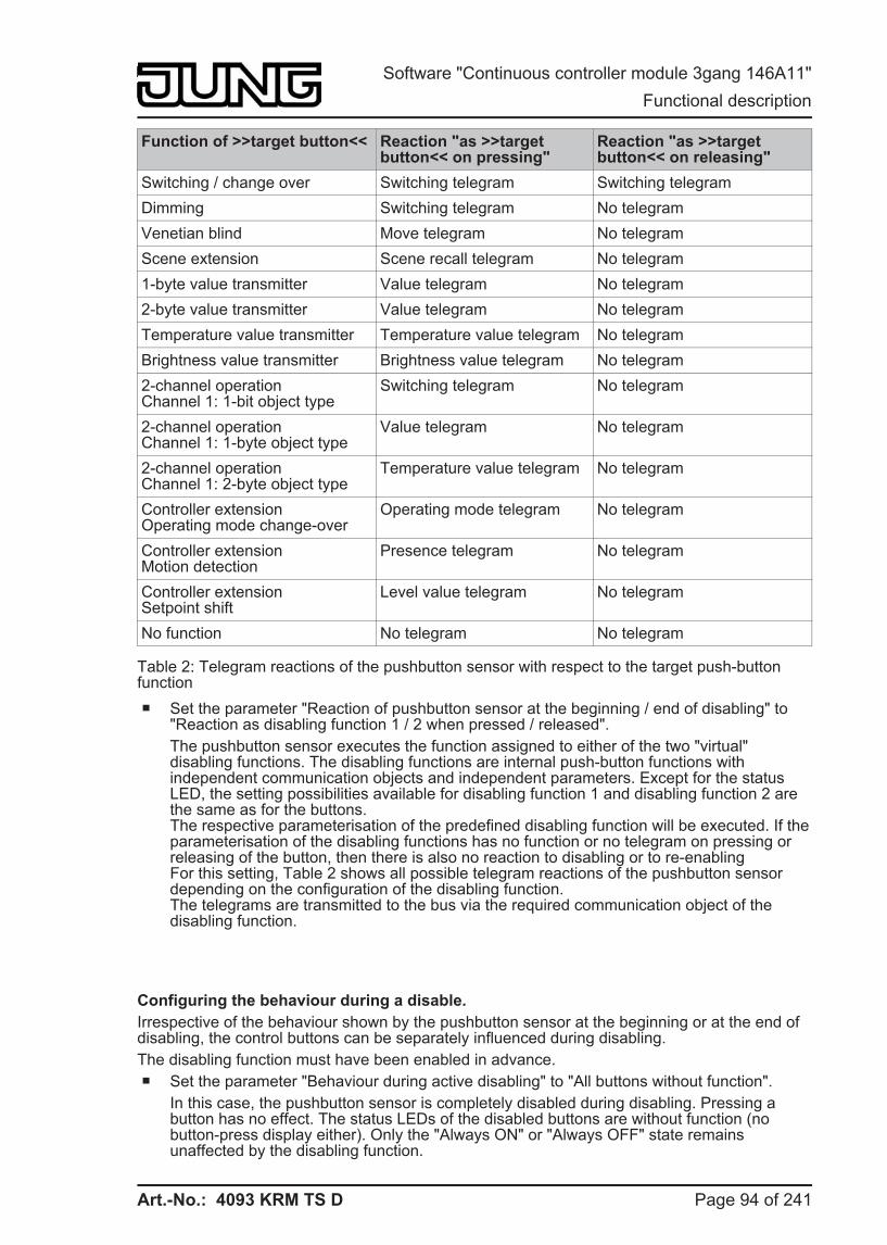
Art.-No.: 4093 KRM TS D
Function of >>target button<< Reaction "as >>target button<< on pressing"
Reaction "as >>target button<< on releasing"
Switching / change over Switching telegram Switching telegram Dimming Switching telegram No telegram Venetian blind Move telegram No telegram Scene extension Scene recall telegram No telegram 1-byte value transmitter Value telegram No telegram 2-byte value transmitter Value telegram No telegram Temperature value transmitter Temperature value telegram No telegram Brightness value transmitter Brightness value telegram No telegram 2-channel operationChannel 1: 1-bit object type
Switching telegram No telegram
2-channel operationChannel 1: 1-byte object type
Value telegram No telegram
2-channel operationChannel 1: 2-byte object type
Temperature value telegram No telegram
Controller extensionOperating mode change-over
Operating mode telegram No telegram
Controller extensionMotion detection
Presence telegram No telegram
Controller extensionSetpoint shift
Level value telegram No telegram
No function No telegram No telegram
Table 2: Telegram reactions of the pushbutton sensor with respect to the target push-button function o Set the parameter "Reaction of pushbutton sensor at the beginning / end of disabling" to
"Reaction as disabling function 1 / 2 when pressed / released". The pushbutton sensor executes the function assigned to either of the two "virtual" disabling functions. The disabling functions are internal push-button functions with independent communication objects and independent parameters. Except for the status LED, the setting possibilities available for disabling function 1 and disabling function 2 are the same as for the buttons.The respective parameterisation of the predefined disabling function will be executed. If the parameterisation of the disabling functions has no function or no telegram on pressing or releasing of the button, then there is also no reaction to disabling or to re-enablingFor this setting, Table 2 shows all possible telegram reactions of the pushbutton sensor depending on the configuration of the disabling function.The telegrams are transmitted to the bus via the required communication object of the disabling function.
Configuring the behaviour during a disable. Irrespective of the behaviour shown by the pushbutton sensor at the beginning or at the end of disabling, the control buttons can be separately influenced during disabling. The disabling function must have been enabled in advance. o Set the parameter "Behaviour during active disabling" to "All buttons without function".
In this case, the pushbutton sensor is completely disabled during disabling. Pressing a button has no effect. The status LEDs of the disabled buttons are without function (no button-press display either). Only the "Always ON" or "Always OFF" state remains unaffected by the disabling function.
Page 94 of 241
Software "Continuous controller module 3gang 146A11" Functional description
Art.-No.: 4093 KRM TS D
o Set the parameter "Behaviour during active disabling" to "all buttons behave like". Also set the parameters "All buttons with even / odd numbers behave during disabling like" to the desired button number, configure module button number or disabling function. All buttons behave as defined in the parameterisation for the two specified reference buttons of the pushbutton sensor. For all control buttons with an even number (2, 4, 6, …) and for all buttons with an odd number (1, 3, 5, …) it is possible to program not only different reference buttons, but also identical reference buttons. The two "virtual" disabling functions of the pushbutton sensor can also be configured as a reference button.The telegrams are transmitted to the bus via the communication objects of the specified reference buttons. The status LEDs of the reference buttons are controlled according to their function. The status LEDs of the disabled buttons are without function (no button-press display either). Only the "Always ON" or "Always OFF" state remains unaffected by the disabling function.
o Set the parameter "Behaviour during active disabling" to "Individual buttons without function". The buttons that will be disabled are defined on the parameter page "Disable - Button selection" page. Only the individually specified buttons are locked during disabling. The other control buttons remain unaffected by disabling. The status LEDs of the disabled buttons are without function (no button-press display either). Only the "Always ON" or "Always OFF" state remains unaffected by the disabling function.
o Set the parameter "Behaviour during active disabling" to "Individual buttons behave like". The buttons that will be disabled are defined on the parameter page "Disable - Button selection" page. Also set the parameters "All buttons with even / odd numbers behave during disabling like" to the desired button number, configure module button number or disabling function. Only the individually specified buttons behave as defined in the parameterisation of the two specified reference buttons of the pushbutton sensor. For all control buttons with an even number (2, 4, 6, …) and for all buttons with an odd number (1, 3, 5, …) it is possible to program not only different reference buttons, but also identical reference buttons. The two "virtual" disabling functions of the pushbutton sensor can also be configured as a reference button. The buttons that will be disabled are defined in the parameters on the "Disable - buttons selection" page.The telegrams are transmitted to the bus via the communication objects of the specified reference buttons. The status LEDs of the reference buttons are controlled according to their function. The status LEDs of the disabled buttons are without function (no button-press display either). Only the "Always ON" or "Always OFF" state remains unaffected by the disabling function.
i If a button evaluation is taking place at the time of activation / deactivation of a disabling function, this function is aborted immediately and with it also the pertaining push-button function. It is first necessary to release all buttons before a new push-button function can be executed if so permitted by the state of disabling.
Page 95 of 241
Software "Continuous controller module 3gang 146A11" Functional description
Art.-No.: 4093 KRM TS D
4.2.4.1.15 Transmission delay After a reset (e.g. after loading of an application program or the physical address or after switch-on of the bus voltage), the device can automatically transmit telegrams for the "Controller extension" function. The controller extension then attempts to retrieve values from the room temperature controller by means of read telegrams in order to update the object states (see page 158). This update takes place for all the transmitting objects with the name "T.Controller extension" and additionally for the objects "D.Input controller ext. status signal addition" and "D.Input controller ext. ventilation visualisation".After a device reset, the telegrams for room temperature measurements are also automatically transmitted to the bus.
If, in addition to the pushbutton sensor, there are still other devices installed in the bus which transmit telegrams immediately after a reset, it may be useful to activate the transmit delay for automatically transmitting objects of the controller extension and the room temperature measurement in the "General" parameter node in order to reduce the bus load. When transmit delay is activated, the pushbutton sensor determines the value of its individual delay from the device number of its physical address (phys. address: area.line.device number). This value can be about 30 seconds maximum. Without setting a special time delay, this principle prevents multiple pushbutton sensors from trying to transmit telegrams to the bus at the same time.
i The transmit delay is not active for the rocker and push-button functions of the pushbutton sensor. In addition, the controller objects are not influenced by the transmission delay.
Page 96 of 241
Software "Continuous controller module 3gang 146A11" Functional description
Art.-No.: 4093 KRM TS D
4.2.4.1.16 Alarm message The device permits signalling of a alarm which might be, for instance, a burglar or a fire alarm from a KNX/EIB central alarm unit. An alarm is signalled by all status LEDs and of the operation LED of the pushbutton sensor flashing synchronously. This alarm indication can be separately enabled with the parameter "Alarm message indication" on parameter page "Alarm messages" so that it can be used.
When alarm messages are enabled, the ETS displays the communication object "Alarm message" and further alarm function parameters.The alarm message object is used as an input for activating or deactivating the alarm indication. The polarity of the object can be selected. When the object value corresponds to the "Alarm" condition, all status LEDs and the operation LED are always flashing with a frequency of approx. 2 Hz. If there is an alarm, the basic parameterisations of the LED have no significance. The LEDs adopt their originally configured behaviour only after the alarm indication has been deactivated. Changes of the state of the LEDs during an alarm - if they are controlled by separate LED objects or if they signal push-button functions - are internally stored and recovered at the end of the alarm.
Apart from the possibility of deactivating an alarm indication via the alarm object, it can also be deactivated locally by a button-press on the pushbutton sensor itself. The parameter "Reset alarm message by a button-press?" defines the button response during an alarm… - If this parameter is set to "Yes", an active alarm indication can be deactivated by a button-
press on the pushbutton sensor. This button-press does not cause the configured push-button function of the pressed button to be executed. Only after then next button-press will the parameterisation of the button be evaluated and a telegram be transmitted to the bus, if applicable.
- If "No" has been selected, an alarm indication can only be deactivated via the alarm message object. A button-press will always directly execute the configured push-button function.
If an alarm indication can be deactivated by a button-press, the parameter "Acknowledge alarm message by" defines whether an additional alarm acknowledge telegram is to be transmitted to the bus via the separate object "Alarm message acknowledge" after triggering by this button-press.Such an acknowledge telegram can, for instance, be sent via a 'listening' group address to the "Alarm message" objects of other pushbutton sensors in order to reset the alarm status there as well. Attention must be paid during resetting of an alarm to the selectable polarity of the acknowledge object.
i Notes on the polarity of the alarm object: If the setting is "Alarm when OFF and alarm reset when ON", the alarm object must be actively written by the bus with "0" to activate the alarm after a reset or after programming with the ETS.
i An active alarm message is not stored so that the alarm indication is generally deactivated after a reset or after programming with the ETS.
Page 97 of 241
Software "Continuous controller module 3gang 146A11" Functional description
Art.-No.: 4093 KRM TS D
4.2.4.2 Room temperature controller The device can be used for single-room temperature control. Depending on the operating mode, the current temperature setpoint and on the room temperature, command values for heating or cooling control and fan control can be sent to the KNS / EIB. Usually, these command values are then converted by a suitable KNX/EIB actuator, e.g. heating or switching actuators or directly by bus-compatible actuating drives, evaluated and converted to physical variables for air conditioning control.
The room temperature controller is an independent function section of the device. It has its own parameter and object range in the ETS configuration. Therefore, the room temperature controller can be switched on or off, irrespective of the pushbutton sensor function.The controller function section of the device can either work as a main controller or as a controller extension. As the main controller, the room temperature controller function is fully switched on and the control algorithm activated. Only the main controller transmits control value telegrams. A controller extension itself is not involved in the regulating process. With it, the user can operate the single-room controller, i.e. the main controller from different places in the room. In this way, any number of operating extensions can be set up.
In this chapter, the functions of the room temperature controller are described as a main controller.
4.2.4.2.1 Operating modes and operating mode change-over
Introduction The room temperature controller distinguishes between two different operating modes. The operating modes specify whether you want the controller to use its variable to trigger heating systems ("heating" single operating mode) or cooling systems ("cooling" single operating mode). You can also activate mixed operation, with the controller being capable of changing over between "Heating" and "Cooling" either automatically or, alternatively, controlled by a communication object.In addition, you can establish two-level control operation to control an additional heating or cooling unit. For two-level feedback control, separate command values will be calculated as a function of the temperature deviation between the setpoint and the actual value and transmitted to the bus for the basic and additional levels. The parameter "Controller operating mode" in the "Room temperature control -> Controller general" parameter branch specifies the operating mode and, if necessary, enables the additional level(s).
"Heating" or "cooling" single operating modes In the single "Heating" or "Cooling" operating modes without any additional level, the controller will always work with one command value and, alternatively, when the additional level is enabled, it will use two command value in the configured operating mode. Depending on the room temperature determined and on the specified setpoint temperatures of the operating modes (see chapter 4.2.4.2.4. Operating mode change-over), the room temperature controller will automatically decide whether heating or cooling energy is required and calculates the command value for the heating or cooling system.
Page 98 of 241
Software "Continuous controller module 3gang 146A11" Functional description
Art.-No.: 4093 KRM TS D
"Heating and cooling" mixed operating mode
In the "Heating and cooling" mixed operating mode, the controller is capable of triggering heating and cooling systems. In this connection, you can set the change-over behaviour of the operating modes...
- "Change over between heating and cooling" parameter in the "Room temperature controller -> Controller general" parameter branch set to "Automatic".In this case, a heating or cooling mode will be automatically activated, depending on the room temperature determined and on the given temperature basic setpoint, or on the deadband, respectively. If the room temperature is within the preset deadband neither heating nor cooling will take place (both command values = "0"). In this connection, the display will read the heating temperature setpoint of the activated operating mode when you actuate the display buttons. If the room temperature is higher than the cooling temperature setpoint cooling will take place. If the room temperature is lower than the cooling temperature setpoint heating will take place.When the heating/cooling operating mode is changed over automatically, the information can be actively sent to the bus via the object "Heating/cooling change-over" to indicate whether the controller is working in the heating mode ("1" telegram) or in the cooling mode ("0" telegram). In this connection, the "Automatic heating/cooling change-over transmission" parameter specifies when an operating mode change-over will be transmitted...Setting "On changing the operating mode": in this case, a telegram will be transmitted solely on change-over from heating to cooling (object value = "0") or from cooling to heating (object value = "1"), respectively.- Setting "On changing the output command value": with this setting, the current operating mode will be transmitted whenever there is a modification of the output command value. If the command value = "0" the operating mode which was active last will be transmitted. If the room temperature determined is within the deadband, the operating mode activated last will be retained in the object value until a change-over to the other operating mode takes place, if necessary. In addition, the object value can be output in cycles when automatic change-over is being carried out.The "Cyclical transmission heating/cooling change-over" parameter enables cyclic transmission (factor > "0" setting) and specifies the cycle time.With an automatic operating mode change-over, it should be noted that under certain circumstances there will be continuous change-over between heating and cooling if the deadband is too small. For this reason, you should, if possible, not set the deadband (temperature difference between the setpoint temperatures for the comfort heating and cooling modes) below the default value (2 K).
Page 99 of 241
Software "Continuous controller module 3gang 146A11" Functional description
Art.-No.: 4093 KRM TS D
- "Change-over between heating and cooling" parameter in the "Room temperature controller -> Controller general" parameter branch set to "Via object".In this case, the operating mode is controlled via the object "Heating/cooling change-over", irrespective of the deadband. This type of change-over can, for example, become necessary if both heating and cooling should be carried out through a one-pipe system (heating and cooling system). For this, the temperature of the medium in the single-pipe system must be changed via the system control. Afterwards the heating/cooling operating mode is set via the object (often the single-pipe system uses cold water for cooling during the summer, hot water for heating during the winter).The "Heating/cooling change-over" object has the following polarities: "1": heating; "0" cooling. After a reset, the object value will be "0", and the "Heating/cooling operating mode change-over after reset" set in the ETS will be activated. You can use the "Heating/cooling operating mode after reset" parameter to set which mode you want to activate after a reset. For the "Heating" or "Cooling" settings, the controller will activate the configured heating/cooling operating mode immediately after the initialisation phase. In case of parameterisation "Operating mode before reset" the operating mode which was selected before the reset will be activated.If a change-over is made through the object the operating mode will first be changed into the one specified to be activated after a reset. A change-over to the other operating mode will only take place after the device receives an object update, if necessary.Notes on the setting "Operating mode before reset": frequent changing of the operating mode (e. g. several times a day) during running operation can adversely affect the life of the device as the read-only memory (EEPROM) used has been designed for less frequent write access events only.
It is not possible to heat and cool at the same time (command value > "0"). Only with PWM is it possible that a short-time 'command value overlapping' could occur during the transition between heating and cooling, due to the matching of the command value at the end of a time cycle. However, such overlapping will be corrected at the end of a PWM time cycle. Only if heating or cooling energy is required in one of the operating modes and, consequently, the command value is > "0" the " â " or " è " symbol will appear on the display.
Heating/cooling message Depending on the set operating mode, separate objects can be used to signal whether the controller is currently demanding heating or cooling energy and is thus actively heating â or cooling è. As long as the heating command value is > "0", a "1" telegram will be transmitted through the "Heating" signal object. The signal telegram is only reset when the command value is "0" ("0" telegram is transmitted). The same applies to the signal object for cooling.
i With 2-point feedback control, it should be noted that the â or è symbols will light up on the display or that the message objects for heating and cooling will already become active as soon as the temperature falls short of the temperature setpoint of the active operating mode in case of heating or exceeds the temperature setpoint in case of cooling. In this case, the configured hysteresis is not taken into account.
The signal objects can be enabled by the "Heating message" or "Cooling message" parameters in the "Room temperature control -> Command value and status output" parameter branch. The control algorithm controls the signal objects. Please note that the command value is recalculated every 30 s, followed by an updating of the signal objects.
Page 100 of 241
Software "Continuous controller module 3gang 146A11" Functional description
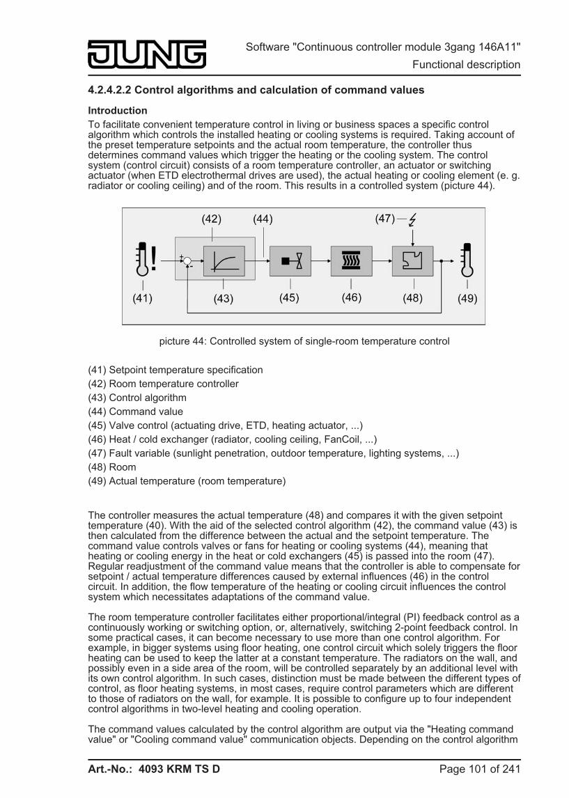
Art.-No.: 4093 KRM TS D
4.2.4.2.2 Control algorithms and calculation of command values
Introduction To facilitate convenient temperature control in living or business spaces a specific control algorithm which controls the installed heating or cooling systems is required. Taking account of the preset temperature setpoints and the actual room temperature, the controller thus determines command values which trigger the heating or the cooling system. The control system (control circuit) consists of a room temperature controller, an actuator or switching actuator (when ETD electrothermal drives are used), the actual heating or cooling element (e. g. radiator or cooling ceiling) and of the room. This results in a controlled system (picture 44).
picture 44: Controlled system of single-room temperature control
(41) Setpoint temperature specification (42) Room temperature controller (43) Control algorithm (44) Command value (45) Valve control (actuating drive, ETD, heating actuator, ...) (46) Heat / cold exchanger (radiator, cooling ceiling, FanCoil, ...) (47) Fault variable (sunlight penetration, outdoor temperature, lighting systems, ...) (48) Room (49) Actual temperature (room temperature)
The controller measures the actual temperature (48) and compares it with the given setpoint temperature (40). With the aid of the selected control algorithm (42), the command value (43) is then calculated from the difference between the actual and the setpoint temperature. The command value controls valves or fans for heating or cooling systems (44), meaning that heating or cooling energy in the heat or cold exchangers (45) is passed into the room (47).Regular readjustment of the command value means that the controller is able to compensate for setpoint / actual temperature differences caused by external influences (46) in the control circuit. In addition, the flow temperature of the heating or cooling circuit influences the control system which necessitates adaptations of the command value.
The room temperature controller facilitates either proportional/integral (PI) feedback control as a continuously working or switching option, or, alternatively, switching 2-point feedback control. In some practical cases, it can become necessary to use more than one control algorithm. For example, in bigger systems using floor heating, one control circuit which solely triggers the floor heating can be used to keep the latter at a constant temperature. The radiators on the wall, and possibly even in a side area of the room, will be controlled separately by an additional level with its own control algorithm. In such cases, distinction must be made between the different types of control, as floor heating systems, in most cases, require control parameters which are different to those of radiators on the wall, for example. It is possible to configure up to four independent control algorithms in two-level heating and cooling operation.
The command values calculated by the control algorithm are output via the "Heating command value" or "Cooling command value" communication objects. Depending on the control algorithm
Page 101 of 241
Software "Continuous controller module 3gang 146A11" Functional description
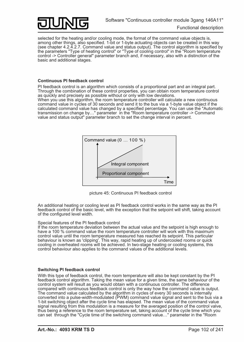
Art.-No.: 4093 KRM TS D
selected for the heating and/or cooling mode, the format of the command value objects is, among other things, also specified. 1-bit or 1-byte actuating objects can be created in this way (see chapter 4.2.4.2.7. Command value and status output). The control algorithm is specified by the parameters "Type of heating control" or "Type of cooling control" in the "Room temperature control -> Controller general" parameter branch and, if necessary, also with a distinction of the basic and additional stages.
Continuous PI feedback control PI feedback control is an algorithm which consists of a proportional part and an integral part. Through the combination of these control properties, you can obtain room temperature control as quickly and precisely as possible without or only with low deviations.When you use this algorithm, the room temperature controller will calculate a new continuous command value in cycles of 30 seconds and send it to the bus via a 1-byte value object if the calculated command value has changed by a specified percentage. You can use the "Automatic transmission on change by…" parameter in the "Room temperature controller -> Command value and status output" parameter branch to set the change interval in percent.
picture 45: Continuous PI feedback control
An additional heating or cooling level as PI feedback control works in the same way as the PI feedback control of the basic level, with the exception that the setpoint will shift, taking account of the configured level width.
Special features of the PI feedback controlIf the room temperature deviation between the actual value and the setpoint is high enough to have a 100 % command value the room temperature controller will work with this maximum control value until the room temperature measured has reached its setpoint. This particular behaviour is known as 'clipping'. This way, rapid heating up of undercooled rooms or quick cooling in overheated rooms will be achieved. In two-stage heating or cooling systems, this control behaviour also applies to the command values of the additional levels.
Switching PI feedback control With this type of feedback control, the room temperature will also be kept constant by the PI feedback control algorithm. Taking the mean value for a given time, the same behaviour of the control system will result as you would obtain with a continuous controller. The difference compared with continuous feedback control is only the way how the command value is output. The command value calculated by the algorithm in cycles of every 30 seconds is internally converted into a pulse-width-modulated (PWM) command value signal and sent to the bus via a 1-bit switching object after the cycle time has elapsed. The mean value of the command value signal resulting from this modulation is a measure for the averaged position of the control valve, thus being a reference to the room temperature set, taking account of the cycle time which you can set through the "Cycle time of the switching command value…" parameter in the "Room
Page 102 of 241
Software "Continuous controller module 3gang 146A11" Functional description
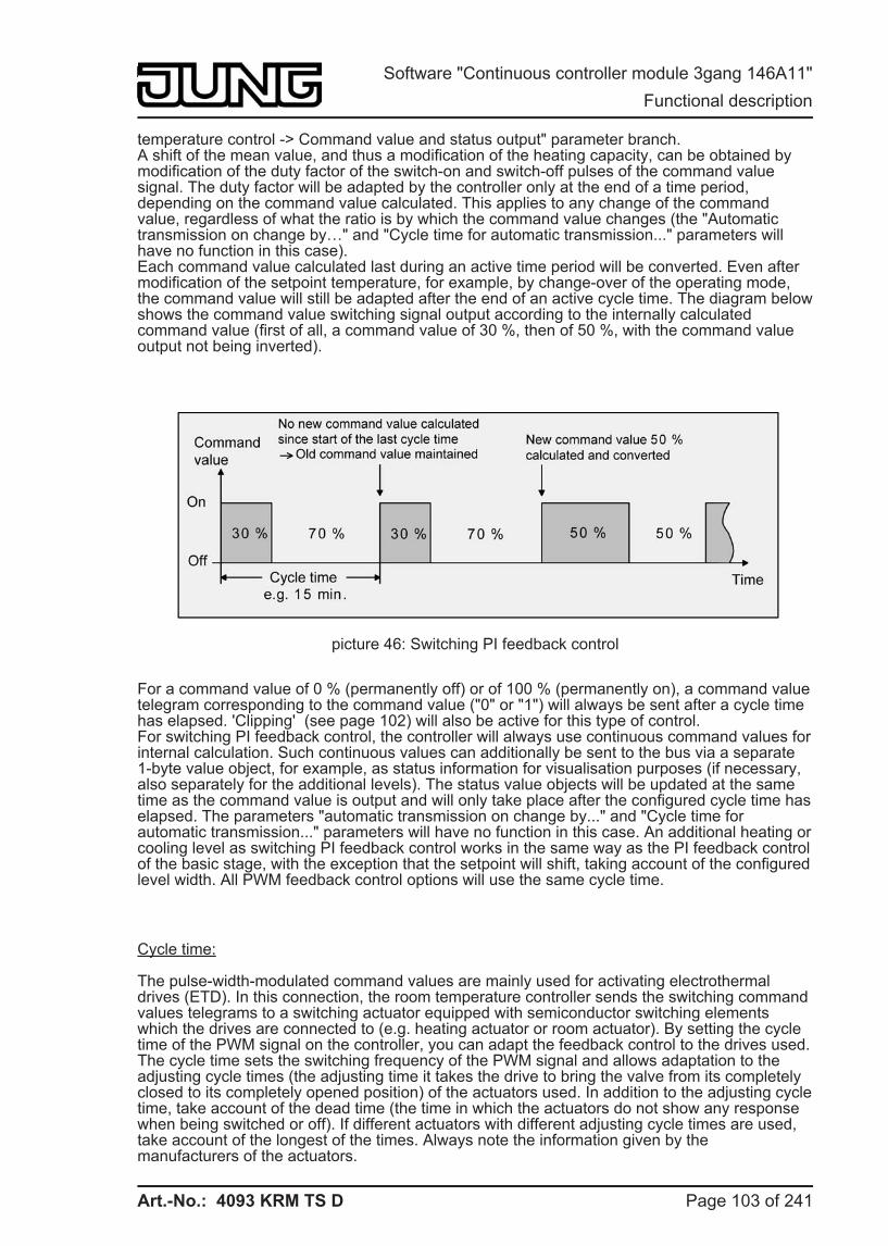
Art.-No.: 4093 KRM TS D
temperature control -> Command value and status output" parameter branch.A shift of the mean value, and thus a modification of the heating capacity, can be obtained by modification of the duty factor of the switch-on and switch-off pulses of the command value signal. The duty factor will be adapted by the controller only at the end of a time period, depending on the command value calculated. This applies to any change of the command value, regardless of what the ratio is by which the command value changes (the "Automatic transmission on change by…" and "Cycle time for automatic transmission..." parameters will have no function in this case).Each command value calculated last during an active time period will be converted. Even after modification of the setpoint temperature, for example, by change-over of the operating mode, the command value will still be adapted after the end of an active cycle time. The diagram below shows the command value switching signal output according to the internally calculated command value (first of all, a command value of 30 %, then of 50 %, with the command value output not being inverted).
picture 46: Switching PI feedback control
For a command value of 0 % (permanently off) or of 100 % (permanently on), a command value telegram corresponding to the command value ("0" or "1") will always be sent after a cycle time has elapsed. 'Clipping' (see page 102) will also be active for this type of control.For switching PI feedback control, the controller will always use continuous command values for internal calculation. Such continuous values can additionally be sent to the bus via a separate 1-byte value object, for example, as status information for visualisation purposes (if necessary, also separately for the additional levels). The status value objects will be updated at the same time as the command value is output and will only take place after the configured cycle time has elapsed. The parameters "automatic transmission on change by..." and "Cycle time for automatic transmission..." parameters will have no function in this case. An additional heating or cooling level as switching PI feedback control works in the same way as the PI feedback control of the basic stage, with the exception that the setpoint will shift, taking account of the configured level width. All PWM feedback control options will use the same cycle time.
Cycle time:
The pulse-width-modulated command values are mainly used for activating electrothermal drives (ETD). In this connection, the room temperature controller sends the switching command values telegrams to a switching actuator equipped with semiconductor switching elements which the drives are connected to (e.g. heating actuator or room actuator). By setting the cycle time of the PWM signal on the controller, you can adapt the feedback control to the drives used. The cycle time sets the switching frequency of the PWM signal and allows adaptation to the adjusting cycle times (the adjusting time it takes the drive to bring the valve from its completely closed to its completely opened position) of the actuators used. In addition to the adjusting cycle time, take account of the dead time (the time in which the actuators do not show any response when being switched or off). If different actuators with different adjusting cycle times are used, take account of the longest of the times. Always note the information given by the manufacturers of the actuators.
Page 103 of 241
Software "Continuous controller module 3gang 146A11" Functional description
Art.-No.: 4093 KRM TS D
During cycle time configuration, a distinction can always be made between two cases...
Case 1: Cycle time > 2 x adjusting cycle time of the electrothermal drives used (ETD)
In this case, the switch-on or switch-off times of the PWM signal are long enough for the actuators to have sufficient time to fully open or fully close within a given time period.
Advantages:The desired mean value for the command value and thus for the required room temperature will be set relatively precisely, even for several actuators triggered at the same time.
Disadvantages:It should be noted, that, due to the full valve lift to be continuously 'swept', the life expectancy of the actuators can diminish. For very long cycle times (> 15 minutes) with less sluggishness in the system, the heat emission into the room, for example, in the vicinity of the radiators, can possibly be non-uniform and be found disturbing. i This setting is recommended for sluggish heating systems (such as underfloor heating). i Even for a bigger number of triggered actuators, maybe of different types, this setting can
be recommended to be able to obtain a better mean value of the adjusting travels of the valves.
Case 2: Cycle time < adjusting cycle time of the electrothermal drives used (ETD)
In this case, the switch-on or switch-off times of the PWM signal are too short for the actuators to have enough time to fully open or fully close within a given period.
Advantages:This setting ensures continuous water flow through the radiators, thus facilitating uniform heat emission into the room.If only one actuator is triggered the controller can continuously adapt the command value to compensate the mean value shift caused by the short cycle time, thus setting the desired room temperature.
Disadvantages:If more than one drive is triggered at the same time the desired mean value will become the command value, which will result in a very poor adjustment of the required room temperature, or in adjustment of the latter with major deviations, respectively.The continuous flow of water through the valve, and thus the continuous heating of the drives causes changes to the dead times of the drives during the opening and closing phase. The short cycle time and the dead times means that the required variable (mean value) is only set with a possibly large deviation. For the room temperature to be regulated constantly after a set time, the controller must continually adjust the command value to compensate for the mean value shift caused by the short cycle time. Usually, the control algorithm implemented in the controller (PI feedback control) ensures that control deviations are compensated. i This setting is recommended for quick-reaction heating systems (such as surface
radiators).
2-point feedback control 2-point feedback control represents a very simple temperature control. For this type of feedback control, two hysteresis temperature values are set. The actuators are triggered by the controller via switch-on and switch-off command value commands (1-bit type). A continuous command value is not calculated for this type of control.The room temperature is also evaluated by this type of control in cycles every 30 seconds. Thus the command values change, if required, only at these times. The disadvantage of a
Page 104 of 241
Software "Continuous controller module 3gang 146A11" Functional description
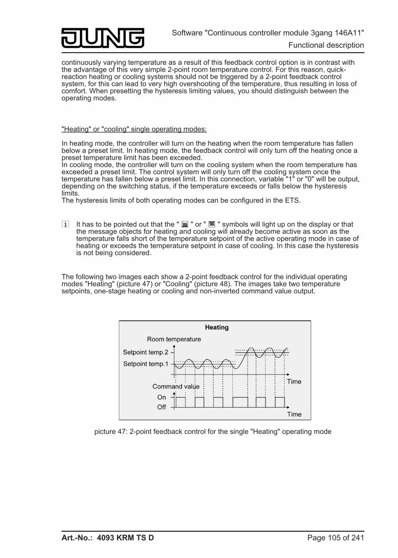
Art.-No.: 4093 KRM TS D
continuously varying temperature as a result of this feedback control option is in contrast with the advantage of this very simple 2-point room temperature control. For this reason, quick-reaction heating or cooling systems should not be triggered by a 2-point feedback control system, for this can lead to very high overshooting of the temperature, thus resulting in loss of comfort. When presetting the hysteresis limiting values, you should distinguish between the operating modes.
"Heating" or "cooling" single operating modes:
In heating mode, the controller will turn on the heating when the room temperature has fallen below a preset limit. In heating mode, the feedback control will only turn off the heating once a preset temperature limit has been exceeded.In cooling mode, the controller will turn on the cooling system when the room temperature has exceeded a preset limit. The control system will only turn off the cooling system once the temperature has fallen below a preset limit. In this connection, variable "1" or "0" will be output, depending on the switching status, if the temperature exceeds or falls below the hysteresis limits.The hysteresis limits of both operating modes can be configured in the ETS.
i It has to be pointed out that the " â " or " è " symbols will light up on the display or that the message objects for heating and cooling will already become active as soon as the temperature falls short of the temperature setpoint of the active operating mode in case of heating or exceeds the temperature setpoint in case of cooling. In this case the hysteresis is not being considered.
The following two images each show a 2-point feedback control for the individual operating modes "Heating" (picture 47) or "Cooling" (picture 48). The images take two temperature setpoints, one-stage heating or cooling and non-inverted command value output.
picture 47: 2-point feedback control for the single "Heating" operating mode
Page 105 of 241
Software "Continuous controller module 3gang 146A11" Functional description
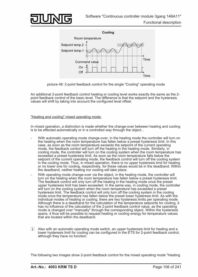
Art.-No.: 4093 KRM TS D
picture 48: 2-point feedback control for the single "Cooling" operating mode
An additional 2-point feedback control heating or cooling level works exactly the same as the 2-point feedback control of the basic level. The difference is that the setpoint and the hysteresis values will shift by taking into account the configured level offset.
"Heating and cooling" mixed operating mode:
In mixed operation, a distinction is made whether the change-over between heating and cooling is to be effected automatically or in a controlled way through the object...
- With automatic operating mode change-over, in the heating mode the controller will turn on the heating when the room temperature has fallen below a preset hysteresis limit. In this case, as soon as the room temperature exceeds the setpoint of the current operating mode, the feedback control will turn off the heating in the heating mode. Similarly, in cooling mode, the controller will turn on the cooling system when the room temperature has exceeded a preset hysteresis limit. As soon as the room temperature falls below the setpoint of the current operating mode, the feedback control will turn off the cooling system in the cooling mode. Thus, in mixed operation, there is no upper hysteresis limit for heating or no lower one for cooling, respectively, for these values would be in the deadband. Within the deadband, neither heating nor cooling will take place.
- With operating mode change-over via the object, in the heating mode, the controller will turn on the heating when the room temperature has fallen below a preset hysteresis limit. The feedback control will only turn off the heating in the heating mode once the preset upper hysteresis limit has been exceeded. In the same way, in cooling mode, the controller will turn on the cooling system when the room temperature has exceeded a preset hysteresis limit. The feedback control will only turn off the cooling system in the cooling mode once the temperature has fallen below the preset lower hysteresis limit. As with the individual modes of heating or cooling, there are two hysteresis limits per operating mode. Although there is a deadband for the calculation of the temperature setpoints for cooling, it has no influence of the calculation of the 2-point feedback control value, as the operating mode is changed over "manually" through the corresponding object. Within the hysteresis spans, it thus will be possible to request heating or cooling energy for temperature values that are located within the deadband.
i Also with an automatic operating mode switch, an upper hysteresis limit for heating and a lower hysteresis limit for cooling can be configured in the ETS for 2-point feedback control, although they have no function.
The following two images show 2-point feedback control for the mixed operating mode "Heating
Page 106 of 241
Software "Continuous controller module 3gang 146A11" Functional description
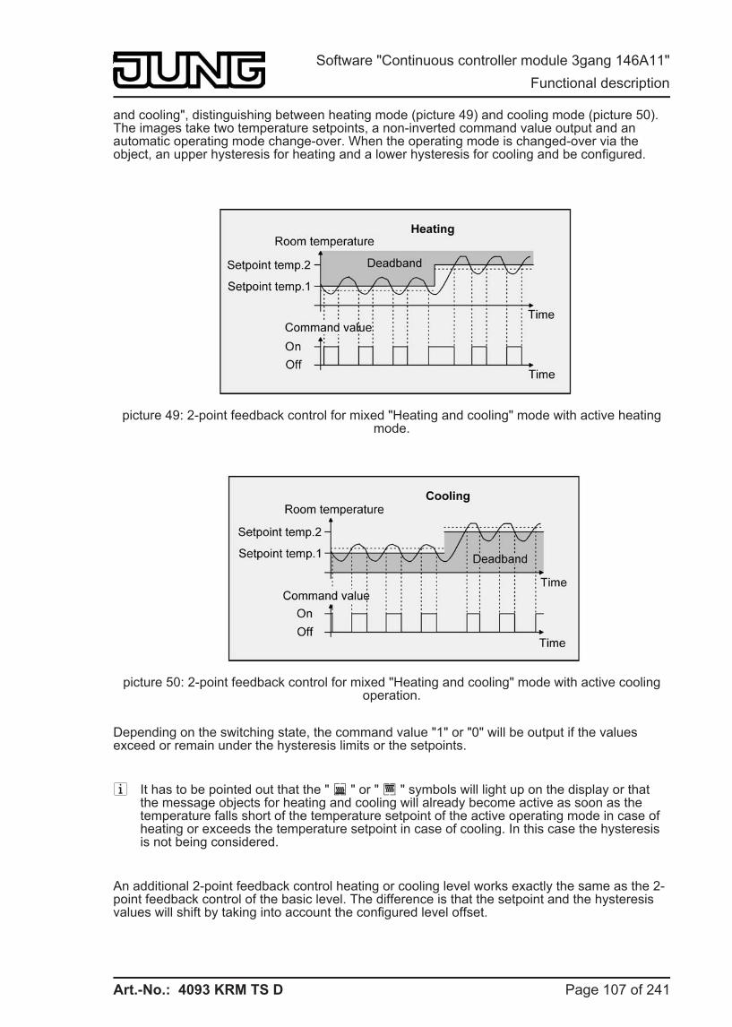
Art.-No.: 4093 KRM TS D
and cooling", distinguishing between heating mode (picture 49) and cooling mode (picture 50). The images take two temperature setpoints, a non-inverted command value output and an automatic operating mode change-over. When the operating mode is changed-over via the object, an upper hysteresis for heating and a lower hysteresis for cooling and be configured.
picture 49: 2-point feedback control for mixed "Heating and cooling" mode with active heating mode.
picture 50: 2-point feedback control for mixed "Heating and cooling" mode with active cooling operation.
Depending on the switching state, the command value "1" or "0" will be output if the values exceed or remain under the hysteresis limits or the setpoints.
i It has to be pointed out that the " â " or " è " symbols will light up on the display or that the message objects for heating and cooling will already become active as soon as the temperature falls short of the temperature setpoint of the active operating mode in case of heating or exceeds the temperature setpoint in case of cooling. In this case the hysteresis is not being considered.
An additional 2-point feedback control heating or cooling level works exactly the same as the 2-point feedback control of the basic level. The difference is that the setpoint and the hysteresis values will shift by taking into account the configured level offset.
Page 107 of 241
Software "Continuous controller module 3gang 146A11" Functional description
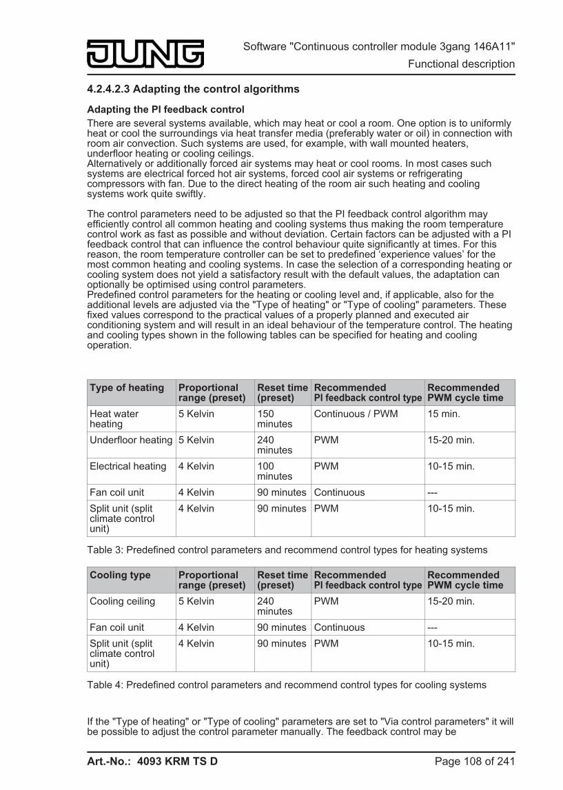
Art.-No.: 4093 KRM TS D
4.2.4.2.3 Adapting the control algorithms
Adapting the PI feedback control There are several systems available, which may heat or cool a room. One option is to uniformly heat or cool the surroundings via heat transfer media (preferably water or oil) in connection with room air convection. Such systems are used, for example, with wall mounted heaters, underfloor heating or cooling ceilings.Alternatively or additionally forced air systems may heat or cool rooms. In most cases such systems are electrical forced hot air systems, forced cool air systems or refrigerating compressors with fan. Due to the direct heating of the room air such heating and cooling systems work quite swiftly.
The control parameters need to be adjusted so that the PI feedback control algorithm may efficiently control all common heating and cooling systems thus making the room temperature control work as fast as possible and without deviation. Certain factors can be adjusted with a PI feedback control that can influence the control behaviour quite significantly at times. For this reason, the room temperature controller can be set to predefined ‘experience values’ for the most common heating and cooling systems. In case the selection of a corresponding heating or cooling system does not yield a satisfactory result with the default values, the adaptation can optionally be optimised using control parameters.Predefined control parameters for the heating or cooling level and, if applicable, also for the additional levels are adjusted via the "Type of heating" or "Type of cooling" parameters. These fixed values correspond to the practical values of a properly planned and executed air conditioning system and will result in an ideal behaviour of the temperature control. The heating and cooling types shown in the following tables can be specified for heating and cooling operation.
Type of heating Proportional range (preset)
Reset time (preset)
Recommended PI feedback control type
Recommended PWM cycle time
Heat waterheating
5 Kelvin 150 minutes
Continuous / PWM 15 min.
Underfloor heating 5 Kelvin 240 minutes
PWM 15-20 min.
Electrical heating 4 Kelvin 100 minutes
PWM 10-15 min.
Fan coil unit 4 Kelvin 90 minutes Continuous --- Split unit (split climate control unit)
4 Kelvin 90 minutes PWM 10-15 min.
Table 3: Predefined control parameters and recommend control types for heating systems
Cooling type Proportional range (preset)
Reset time (preset)
Recommended PI feedback control type
Recommended PWM cycle time
Cooling ceiling 5 Kelvin 240 minutes
PWM 15-20 min.
Fan coil unit 4 Kelvin 90 minutes Continuous --- Split unit (split climate control unit)
4 Kelvin 90 minutes PWM 10-15 min.
Table 4: Predefined control parameters and recommend control types for cooling systems
If the "Type of heating" or "Type of cooling" parameters are set to "Via control parameters" it will be possible to adjust the control parameter manually. The feedback control may be
Page 108 of 241
Software "Continuous controller module 3gang 146A11" Functional description
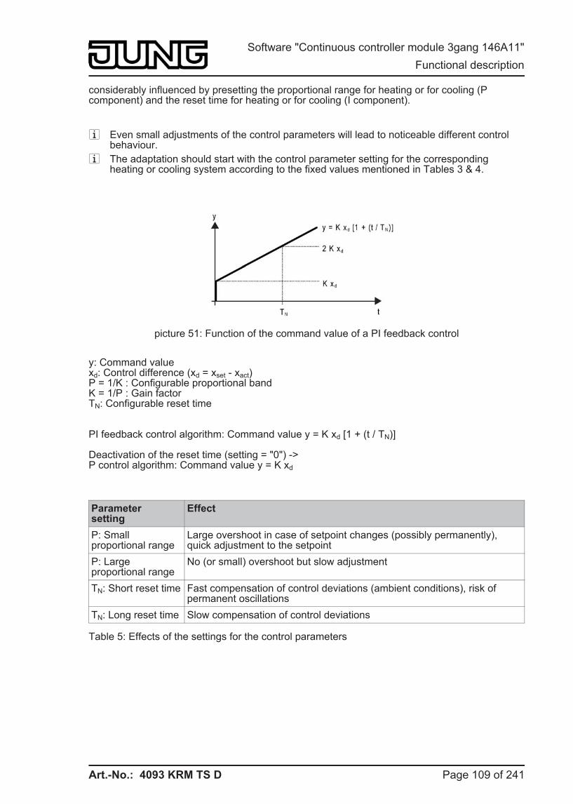
Art.-No.: 4093 KRM TS D
considerably influenced by presetting the proportional range for heating or for cooling (P component) and the reset time for heating or for cooling (I component).
i Even small adjustments of the control parameters will lead to noticeable different control behaviour.
i The adaptation should start with the control parameter setting for the corresponding heating or cooling system according to the fixed values mentioned in Tables 3 & 4.
picture 51: Function of the command value of a PI feedback control
y: Command valuexd: Control difference (xd = xset - xact)P = 1/K : Configurable proportional bandK = 1/P : Gain factorTN: Configurable reset time
PI feedback control algorithm: Command value y = K xd [1 + (t / TN)]
Deactivation of the reset time (setting = "0") ->P control algorithm: Command value y = K xd
Parametersetting
Effect
P: Small proportional range
Large overshoot in case of setpoint changes (possibly permanently), quick adjustment to the setpoint
P: Large proportional range
No (or small) overshoot but slow adjustment
TN: Short reset time Fast compensation of control deviations (ambient conditions), risk of permanent oscillations
TN: Long reset time Slow compensation of control deviations
Table 5: Effects of the settings for the control parameters
Page 109 of 241
Software "Continuous controller module 3gang 146A11" Functional description
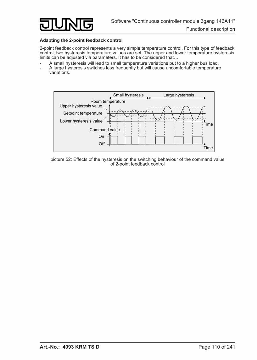
Art.-No.: 4093 KRM TS D
Adapting the 2-point feedback control
2-point feedback control represents a very simple temperature control. For this type of feedback control, two hysteresis temperature values are set. The upper and lower temperature hysteresis limits can be adjusted via parameters. It has to be considered that… - A small hysteresis will lead to small temperature variations but to a higher bus load. - A large hysteresis switches less frequently but will cause uncomfortable temperature
variations.
picture 52: Effects of the hysteresis on the switching behaviour of the command valueof 2-point feedback control
Page 110 of 241
Software "Continuous controller module 3gang 146A11" Functional description
Art.-No.: 4093 KRM TS D
4.2.4.2.4 Operating mode change-over
Introduction - The operating modes
The room temperature controller has various operating modes. The selection of these modes will, for example, facilitate the activation of different temperature setpoints, depending on the presence of a person, on the state of the heating or cooling system, on the time of the day, or on the day of the week. The following operating modes can be distinguished…
- Comfort modeComfort mode is usually activated if persons are in a room, and the room temperature should, for this reason, be adjusted to an adequately convenient value. The change-over to this operating mode can take place either by pressing a button or with presence control, for example, using a PIR monitor on the wall or a motion detector on the ceiling.The activated Comfort mode will be indicated on the display by the ó symbol.
- Standby modeIf a room is not used during the day because persons are absent, you can activate the Standby mode. Thereby, you can adjust the room temperature on a standby value, thus to save heating or cooling energy, respectively. The activated standby mode will be indicated on the display by the ô symbol.
- Night modeDuring the night hours or during the absence of persons for a longer time, it mostly makes sense to adjust the room temperature to lower values for heating systems (e.g. in bedrooms). In this case, cooling system can be set to higher temperature values, if air conditioning is not required (e.g. in offices). For this purpose, you can activate the Night mode.The activated Night mode will be indicated on the display by the õ symbol.
- Frost/heat protection modeFrost protection will be required if, for example, the room temperature must not fall below critical values while the window is open. Heat protection can be required where the temperature rises too much in an environment which is always warm, mainly due to external influences. In such cases, you can activate the Frost/heat protection operating mode and prescribe some temperature setpoint of its own for either option, depending on whether "Heating" or "Cooling" has been selected, to prevent freezing or overheating of the room.The activated Frost/heat protection mode will be indicated on the display by the ö symbol.
- Comfort extension (temporary Comfort mode)You can activate the comfort extension from the night or frost/heat protection mode (not triggered by the "Window status" object) and use it to adjust the room temperature to a comfort value for some time if, for example, the room is also 'used' during the night hours. This mode can exclusively be activated by a presence button or also by the presence object, respectively. The comfort extension option will be automatically deactivated after a definable time has elapsed, or by pressing the presence button once more, or by receiving a presence object value = 0, respectively. You cannot retrigger this extension.The activated comfort extension option will be indicated on the display by the combination of theóõ or óö symbols.
i You can assign an own temperature setpoint to the "Heating" or "Cooling" operating modes for each operating mode.
Page 111 of 241
Software "Continuous controller module 3gang 146A11" Functional description
Art.-No.: 4093 KRM TS D
Operating mode change-over
You can activate or change over the operating modes in various ways. Depending on one another in priority, activation or change-over is possible by… - Local control on the pushbutton sensor using push-button function (controller operating
mode) and configured operating mode change-over, - local control on the pushbutton sensor in the second operating level (if enabled), - The KNX/EIB communication objects separately available for each operating mode or
alternatively through the KONNEX objects. In the last case, also through a controller extension.
The following section describes the individual options for changing over the operating modes in more detail.
Change-over of the operating mode in the second display operating levelThe second operating level is called up by pressing buttons 1 and 3 on the device simultaneously (see chapter 2.5.2. Second operating level). At this point, is possible to activate the "Comfort", "Standby", "Night" or "Frost/heat protection" operating modes from the menu.In the second operating level, it is not possible to change-over to the comfort extension through presence mode. i The presence message, the window status and the forced object for operating mode
change-over (see following sections) have a higher priority than the change-over of the operating mode via the second operating level. Therefore, change-overs by evaluating the appropriate objects have priority.
Change-over of the operating mode using push-button functionAs soon as a button of the pushbutton sensor is configured to "Controller operating mode", the "Operating mode change-over" function can be configured in the button parameters. In this case, a further definition is required in the ETS configuration as to which operating mode is activated when a button is pressed. The "Comfort", "Standby", "Night" and "Frost/heat protection" modes are available for this purpose.To be able to activate the comfort extension, it is possible to use a presence button either optionally or in addition. The presence button, just as with the operating mode change-over, is a push-button function of the pushbutton sensor for the controller operating mode. The presence button means it is possible to change to the comfort extension or to deactivate it prematurely when Night or Frost/heat protection mode (not activated by the "Window status" object) has been activated. Also, it is possible to change over from the Standby to the Comfort mode when the presence button is pressed.The function of the status LED of a button can be configured irrespective of the push-button function. For example, it is possible that the controller status LED is controlled by a separate communication object.
Change-over of the operating mode using KNX/EIB communication objectsA distinction is made whether the operating modes should be changed over via separate 1-bit objects or, alternatively, by the 1-byte KONNEX objects.
Page 112 of 241
Software "Continuous controller module 3gang 146A11" Functional description
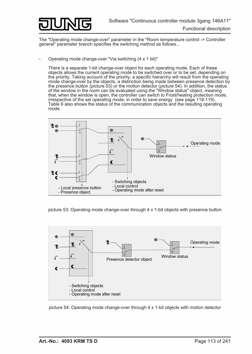
Art.-No.: 4093 KRM TS D
The "Operating mode change-over" parameter in the "Room temperature control -> Controller general" parameter branch specifies the switching method as follows...
- Operating mode change-over "Via switching (4 x 1 bit)"
There is a separate 1-bit change-over object for each operating mode. Each of these objects allows the current operating mode to be switched over or to be set, depending on the priority. Taking account of the priority, a specific hierarchy will result from the operating mode change-over by the objects, a distinction being made between presence detection by the presence button (picture 53) or the motion detector (picture 54). In addition, the status of the window in the room can be evaluated using the "Window status" object, meaning that, when the window is open, the controller can switch to Frost/heating protection mode, irrespective of the set operating mode, in order to save energy (see page 118-119).Table 6 also shows the status of the communication objects and the resulting operating mode.
picture 53: Operating mode change-over through 4 x 1-bit objects with presence button
picture 54: Operating mode change-over through 4 x 1-bit objects with motion detector
Page 113 of 241
Software "Continuous controller module 3gang 146A11" Functional description
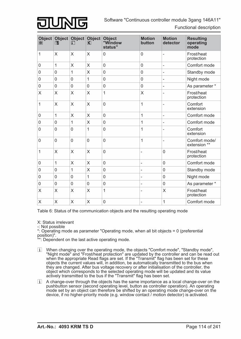
Art.-No.: 4093 KRM TS D
Objectö
Objectó
Objectô
Objectõ
Object"Windowstatus"
Motionbutton
Motiondetector
Resulting operating mode
1 X X X 0 0 - Frost/heat protection
0 1 X X 0 0 - Comfort mode 0 0 1 X 0 0 - Standby mode 0 0 0 1 0 0 - Night mode 0 0 0 0 0 0 - As parameter * X X X X 1 X - Frost/heat
protection 1 X X X 0 1 - Comfort
extension 0 1 X X 0 1 - Comfort mode 0 0 1 X 0 1 - Comfort mode 0 0 0 1 0 1 - Comfort
extension 0 0 0 0 0 1 - Comfort mode/
extension ** 1 X X X 0 - 0 Frost/heat
protection 0 1 X X 0 - 0 Comfort mode 0 0 1 X 0 - 0 Standby mode 0 0 0 1 0 - 0 Night mode 0 0 0 0 0 - 0 As parameter * X X X X 1 - X Frost/heat
protection X X X X 0 - 1 Comfort mode
Table 6: Status of the communication objects and the resulting operating mode
X: Status irrelevant-: Not possible*: Operating mode as parameter "Operating mode, when all bit objects = 0 (preferential position)".**: Dependent on the last active operating mode.
i When changing over the operating mode, the objects "Comfort mode", "Standby mode", "Night mode" and "Frost/heat protection" are updated by the controller and can be read out when the appropriate Read flags are set. If the "Transmit" flag has been set for these objects the current values will, in addition, be automatically transmitted to the bus when they are changed. After bus voltage recovery or after initialisation of the controller, the object which corresponds to the selected operating mode will be updated and its value actively transmitted to the bus if the "Transmit" flag has been set.
i A change-over through the objects has the same importance as a local change-over on the pushbutton sensor (second operating level, button as controller operation). An operating mode set by an object can therefore be shifted by an operating mode change-over on the device, if no higher-priority mode (e.g. window contact / motion detector) is activated.
Page 114 of 241
Software "Continuous controller module 3gang 146A11" Functional description
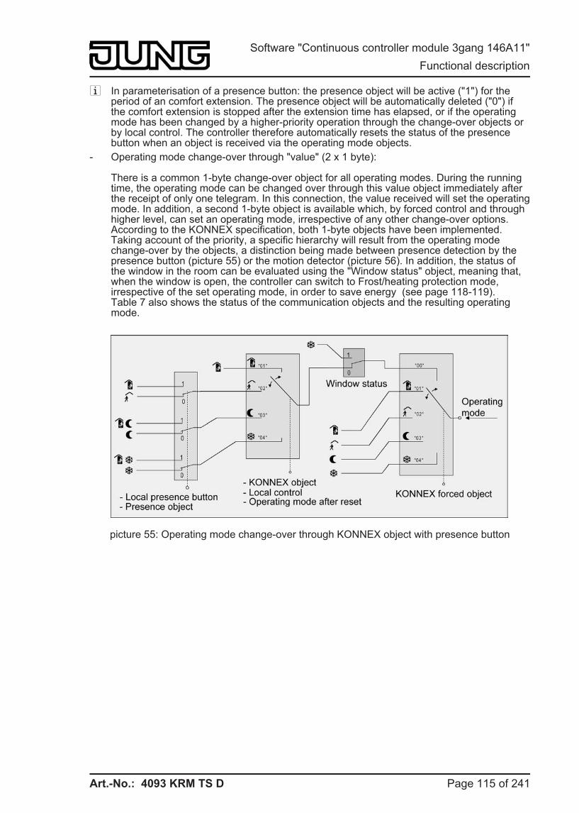
Art.-No.: 4093 KRM TS D
i In parameterisation of a presence button: the presence object will be active ("1") for the period of an comfort extension. The presence object will be automatically deleted ("0") if the comfort extension is stopped after the extension time has elapsed, or if the operating mode has been changed by a higher-priority operation through the change-over objects or by local control. The controller therefore automatically resets the status of the presence button when an object is received via the operating mode objects.
- Operating mode change-over through "value" (2 x 1 byte):
There is a common 1-byte change-over object for all operating modes. During the running time, the operating mode can be changed over through this value object immediately after the receipt of only one telegram. In this connection, the value received will set the operating mode. In addition, a second 1-byte object is available which, by forced control and through higher level, can set an operating mode, irrespective of any other change-over options. According to the KONNEX specification, both 1-byte objects have been implemented.Taking account of the priority, a specific hierarchy will result from the operating mode change-over by the objects, a distinction being made between presence detection by the presence button (picture 55) or the motion detector (picture 56). In addition, the status of the window in the room can be evaluated using the "Window status" object, meaning that, when the window is open, the controller can switch to Frost/heating protection mode, irrespective of the set operating mode, in order to save energy (see page 118-119).Table 7 also shows the status of the communication objects and the resulting operating mode.
picture 55: Operating mode change-over through KONNEX object with presence button
Page 115 of 241
Software "Continuous controller module 3gang 146A11" Functional description
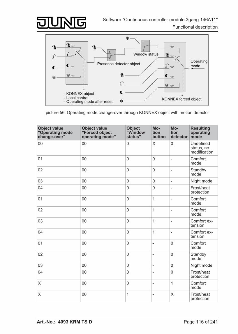
Art.-No.: 4093 KRM TS D
picture 56: Operating mode change-over through KONNEX object with motion detector
Object value"Operating modechange-over"
Object value"Forced objectoperating mode"
Object"Windowstatus"
Mo-tionbutton
Mo-tiondetector
Resulting operating mode
00 00 0 X 0 Undefined status, no modification
01 00 0 0 - Comfort mode
02 00 0 0 - Standby mode
03 00 0 0 - Night mode 04 00 0 0 - Frost/heat
protection 01 00 0 1 - Comfort
mode 02 00 0 1 - Comfort
mode 03 00 0 1 - Comfort ex-
tension 04 00 0 1 - Comfort ex-
tension 01 00 0 - 0 Comfort
mode 02 00 0 - 0 Standby
mode 03 00 0 - 0 Night mode 04 00 0 - 0 Frost/heat
protection X 00 0 - 1 Comfort
mode X 00 1 - X Frost/heat
protection
Page 116 of 241
Software "Continuous controller module 3gang 146A11" Functional description
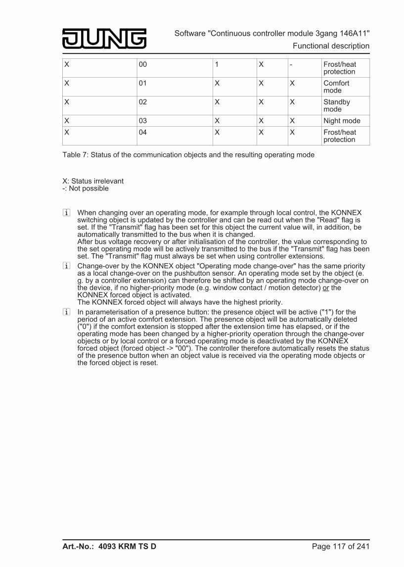
Art.-No.: 4093 KRM TS D
X 00 1 X - Frost/heat protection
X 01 X X X Comfort mode
X 02 X X X Standby mode
X 03 X X X Night mode X 04 X X X Frost/heat
protection
Table 7: Status of the communication objects and the resulting operating mode
X: Status irrelevant-: Not possible
i When changing over an operating mode, for example through local control, the KONNEX switching object is updated by the controller and can be read out when the "Read" flag is set. If the "Transmit" flag has been set for this object the current value will, in addition, be automatically transmitted to the bus when it is changed.After bus voltage recovery or after initialisation of the controller, the value corresponding to the set operating mode will be actively transmitted to the bus if the "Transmit" flag has been set. The "Transmit" flag must always be set when using controller extensions.
i Change-over by the KONNEX object "Operating mode change-over" has the same priority as a local change-over on the pushbutton sensor. An operating mode set by the object (e.g. by a controller extension) can therefore be shifted by an operating mode change-over on the device, if no higher-priority mode (e.g. window contact / motion detector) or the KONNEX forced object is activated.The KONNEX forced object will always have the highest priority.
i In parameterisation of a presence button: the presence object will be active ("1") for the period of an active comfort extension. The presence object will be automatically deleted ("0") if the comfort extension is stopped after the extension time has elapsed, or if the operating mode has been changed by a higher-priority operation through the change-over objects or by local control or a forced operating mode is deactivated by the KONNEX forced object (forced object -> "00"). The controller therefore automatically resets the status of the presence button when an object value is received via the operating mode objects or the forced object is reset.
Page 117 of 241
Software "Continuous controller module 3gang 146A11" Functional description
Art.-No.: 4093 KRM TS D
Additional information on the Presence function / Comfort extension
With presence detection, the room temperature controller can quickly change over to a comfort extension upon pushbutton actuation or go into the Comfort mode when movement by a person in the room is detected. In this connection, the "Presence detection" parameter in the "Room temperature controller -> Controller functionality" parameter node sets whether presence detection should be movement-controlled by a motion detector or manual through presence button actuation...
- Presence detection by the presence buttonIf the presence button is configured for presence detection, you can select the "Presence button" setting in the "Controller operating mode" pushbutton sensor push-button functions. In addition, the "Presence object" is enabled. In this way, you can actuate the presence button or use a presence object value = "1" to change over to comfort extension when the Night or the Frost/heat protection mode is active (not activated by the "window status" object). The extension will be automatically deactivated as soon as the configured "Length of comfort extension" time has elapsed. If you press the presence button once more, or if the presence object receives a value ="0", you can deactivate the comfort extension earlier. You cannot re-trigger such extension time.If you have set the length of comfort extension to "0" in the ETS, you cannot activate a comfort extension from the night or frost/heat protection mode. In this case, the operating mode will not be changed, although the presence function has been activated.If the standby mode is active you can operate the presence button or use a presence object value = "1" to change over to the comfort mode. This will also be the case if you have configured the length of comfort extension to "0". The comfort mode will remain active as long as the presence function remains active, or until another operating mode comes into effect.The presence object or the presence function, respectively, will always be deleted whenever a change-over to a different operating mode takes place, or after a forced operating mode has been deactivated (associated with KONNEX forced change-over). A presence function activated before a device reset (programming operation, bus voltage failure) is always deleted, along with the object value, after the reset.
- Presence detection by the motion detectorIf a motion detector is configured for motion detection, then the controller only evaluates the "Presence object". With this object, it is possible to integrate motion detectors into room temperature control. If a movement is detected ("1" telegram) the controller will change over into the Comfort mode. In this connection, it is irrelevant what has been set by the change-over objects or by local control directly on the device. Only a window contact or the KONNEX forced object are of higher priority.After the movement delay time has elapsed in the motion detector ("0" telegram), the controller will return to the operating mode which was active before presence detection, or it will compensate the telegrams of the operating mode objects received during presence detection, respectively. During active presence detection, you cannot change-over the operating mode on the room temperature controller.A presence function activated before a device reset (programming operation, bus voltage failure) is always deleted, along with the object value, after the reset. In this case, the motion detector must transmit a new "1" telegram to the controller to activate the presence function.
i If the motion detector is configured for presence detection, it is always possible to configure the presence button in the "Controller operating mode" pushbutton sensor push-button functions. However, this parameterisation then has no effect.
Additional information on the window status The room temperature controller offers various options to change over into the Frost/heat protection mode. In addition to the change-over by the corresponding operating mode change-over object, a window contact can activate frost/heat protection. With these options, the window
Page 118 of 241
Software "Continuous controller module 3gang 146A11" Functional description
Art.-No.: 4093 KRM TS D
contact has higher priority.A telegram having the value of = "1" (open window) sent to the "Window status" object will activate the frost/heat protection mode. If this is the case, this operating mode cannot be overridden by the operating mode change-over objects (with the exception of the KONNEX override object).Only a telegram with the value of = "0" (closed window) will reset the window status and deactivate the frost/heat protection mode, if it wasn't set in another way. The operating mode set before the opening of the window or that mode carried by the bus while the window was open is then activated.
Additional information on the operating mode after a reset
In the ETS, it is possible to use the "Operating mode after reset" parameter in the "Room temperature controller / Controller general" parameter node to set which operating mode should be activated after bus voltage recovery or re-programming by the ETS. The following settings are possible...
- "Comfort operation" -> The comfort mode will be activated after the initialisation phase. - "Standby mode" -> The standby mode will be activated after the initialisation phase. - "Night operation" -> The night mode will be activated after the initialisation phase. - "Frost/heat protection operation" -> The frost/heat protection mode will be activated after
the initialisation phase.
The objects associated with the activated operating mode will be updated after a reset.
Page 119 of 241
Software "Continuous controller module 3gang 146A11" Functional description
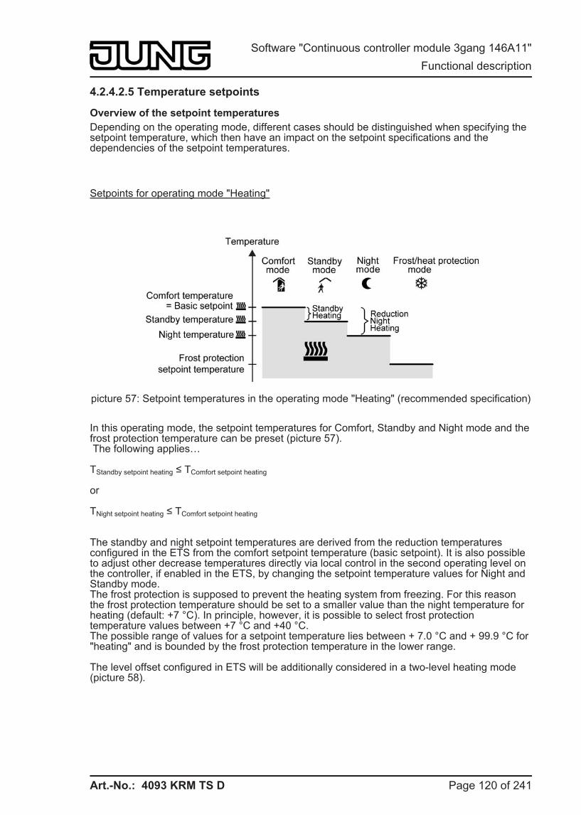
Art.-No.: 4093 KRM TS D
4.2.4.2.5 Temperature setpoints
Overview of the setpoint temperatures Depending on the operating mode, different cases should be distinguished when specifying the setpoint temperature, which then have an impact on the setpoint specifications and the dependencies of the setpoint temperatures.
Setpoints for operating mode "Heating"
picture 57: Setpoint temperatures in the operating mode "Heating" (recommended specification)
In this operating mode, the setpoint temperatures for Comfort, Standby and Night mode and the frost protection temperature can be preset (picture 57). The following applies…
TStandby setpoint heating ≤ TComfort setpoint heating
or
TNight setpoint heating ≤ TComfort setpoint heating
The standby and night setpoint temperatures are derived from the reduction temperatures configured in the ETS from the comfort setpoint temperature (basic setpoint). It is also possible to adjust other decrease temperatures directly via local control in the second operating level on the controller, if enabled in the ETS, by changing the setpoint temperature values for Night and Standby mode.The frost protection is supposed to prevent the heating system from freezing. For this reason the frost protection temperature should be set to a smaller value than the night temperature for heating (default: +7 °C). In principle, however, it is possible to select frost protection temperature values between +7 °C and +40 °C.The possible range of values for a setpoint temperature lies between + 7.0 °C and + 99.9 °C for "heating" and is bounded by the frost protection temperature in the lower range.
The level offset configured in ETS will be additionally considered in a two-level heating mode (picture 58).
Page 120 of 241
Software "Continuous controller module 3gang 146A11" Functional description
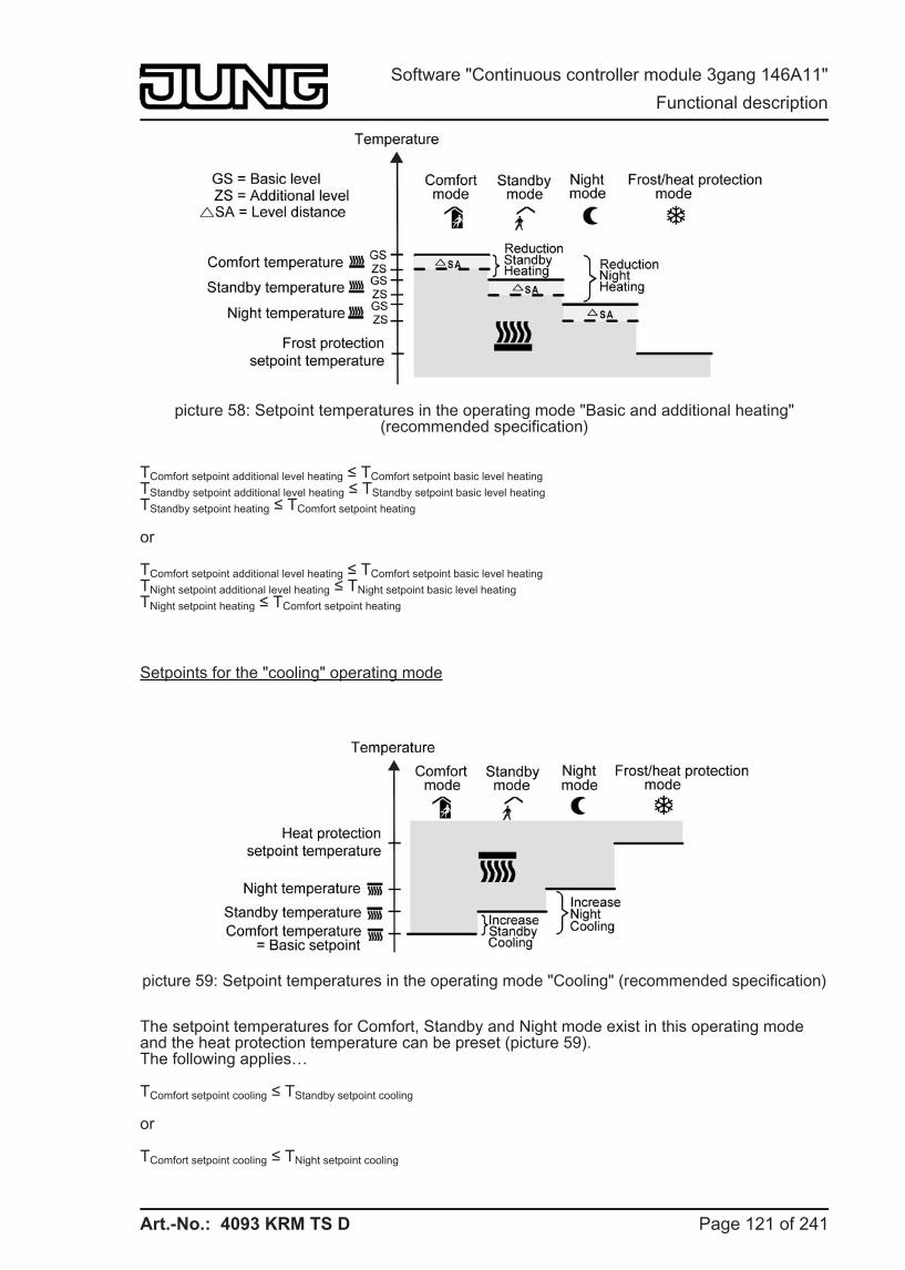
Art.-No.: 4093 KRM TS D
picture 58: Setpoint temperatures in the operating mode "Basic and additional heating" (recommended specification)
TComfort setpoint additional level heating ≤ TComfort setpoint basic level heatingTStandby setpoint additional level heating ≤ TStandby setpoint basic level heatingTStandby setpoint heating ≤ TComfort setpoint heating
or
TComfort setpoint additional level heating ≤ TComfort setpoint basic level heatingTNight setpoint additional level heating ≤ TNight setpoint basic level heatingTNight setpoint heating ≤ TComfort setpoint heating
Setpoints for the "cooling" operating mode
picture 59: Setpoint temperatures in the operating mode "Cooling" (recommended specification)
The setpoint temperatures for Comfort, Standby and Night mode exist in this operating mode and the heat protection temperature can be preset (picture 59).The following applies…
TComfort setpoint cooling ≤ TStandby setpoint cooling
or
TComfort setpoint cooling ≤ TNight setpoint cooling
Page 121 of 241
Software "Continuous controller module 3gang 146A11" Functional description
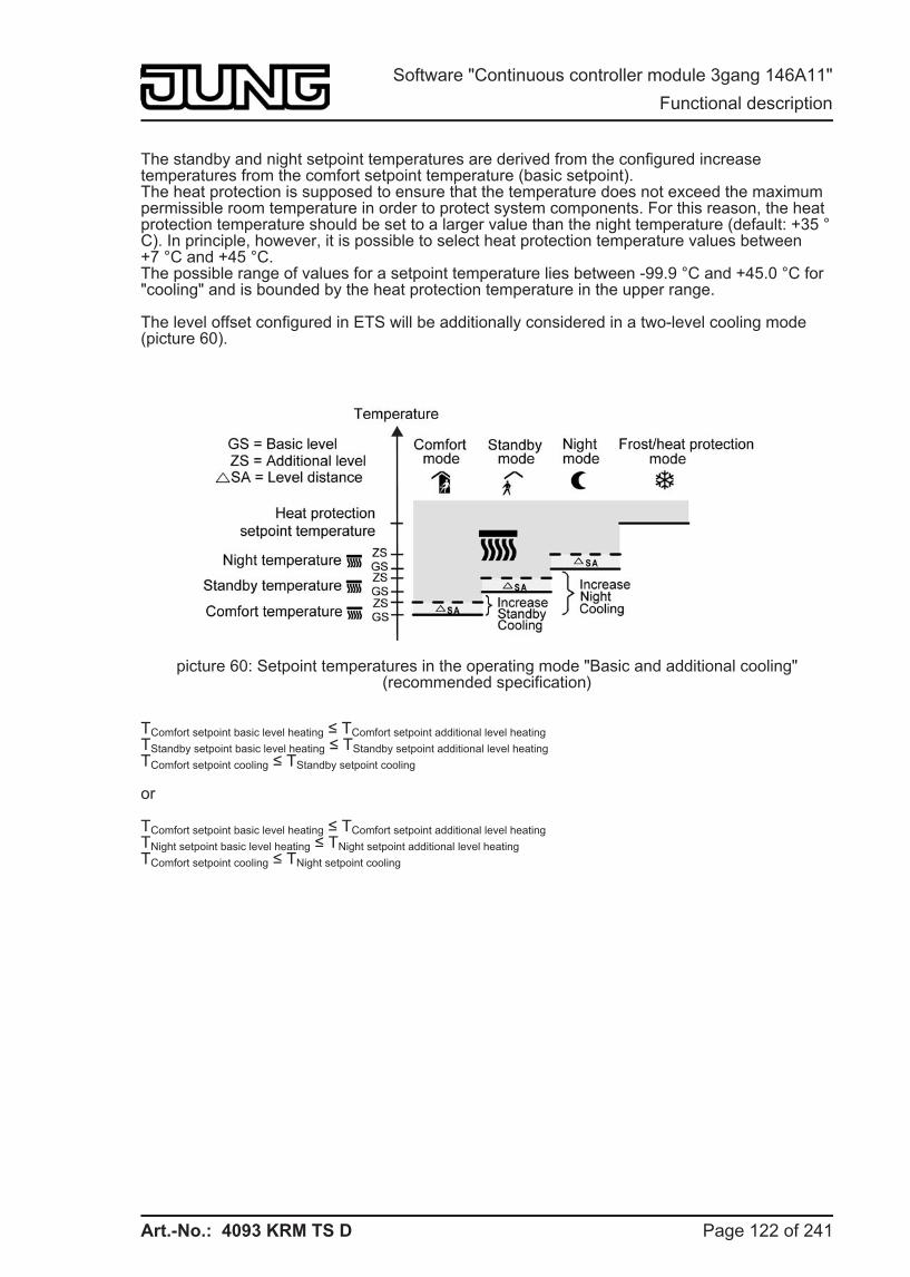
Art.-No.: 4093 KRM TS D
The standby and night setpoint temperatures are derived from the configured increase temperatures from the comfort setpoint temperature (basic setpoint).The heat protection is supposed to ensure that the temperature does not exceed the maximum permissible room temperature in order to protect system components. For this reason, the heat protection temperature should be set to a larger value than the night temperature (default: +35 °C). In principle, however, it is possible to select heat protection temperature values between +7 °C and +45 °C.The possible range of values for a setpoint temperature lies between -99.9 °C and +45.0 °C for "cooling" and is bounded by the heat protection temperature in the upper range.
The level offset configured in ETS will be additionally considered in a two-level cooling mode (picture 60).
picture 60: Setpoint temperatures in the operating mode "Basic and additional cooling" (recommended specification)
TComfort setpoint basic level heating ≤ TComfort setpoint additional level heatingTStandby setpoint basic level heating ≤ TStandby setpoint additional level heatingTComfort setpoint cooling ≤ TStandby setpoint cooling
or
TComfort setpoint basic level heating ≤ TComfort setpoint additional level heatingTNight setpoint basic level heating ≤ TNight setpoint additional level heatingTComfort setpoint cooling ≤ TNight setpoint cooling
Page 122 of 241
Software "Continuous controller module 3gang 146A11" Functional description
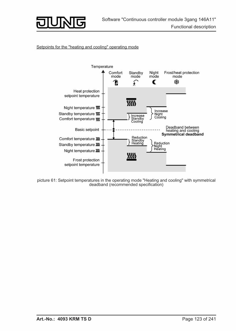
Art.-No.: 4093 KRM TS D
Setpoints for the "heating and cooling" operating mode
picture 61: Setpoint temperatures in the operating mode "Heating and cooling" with symmetrical deadband (recommended specification)
Page 123 of 241
Software "Continuous controller module 3gang 146A11" Functional description
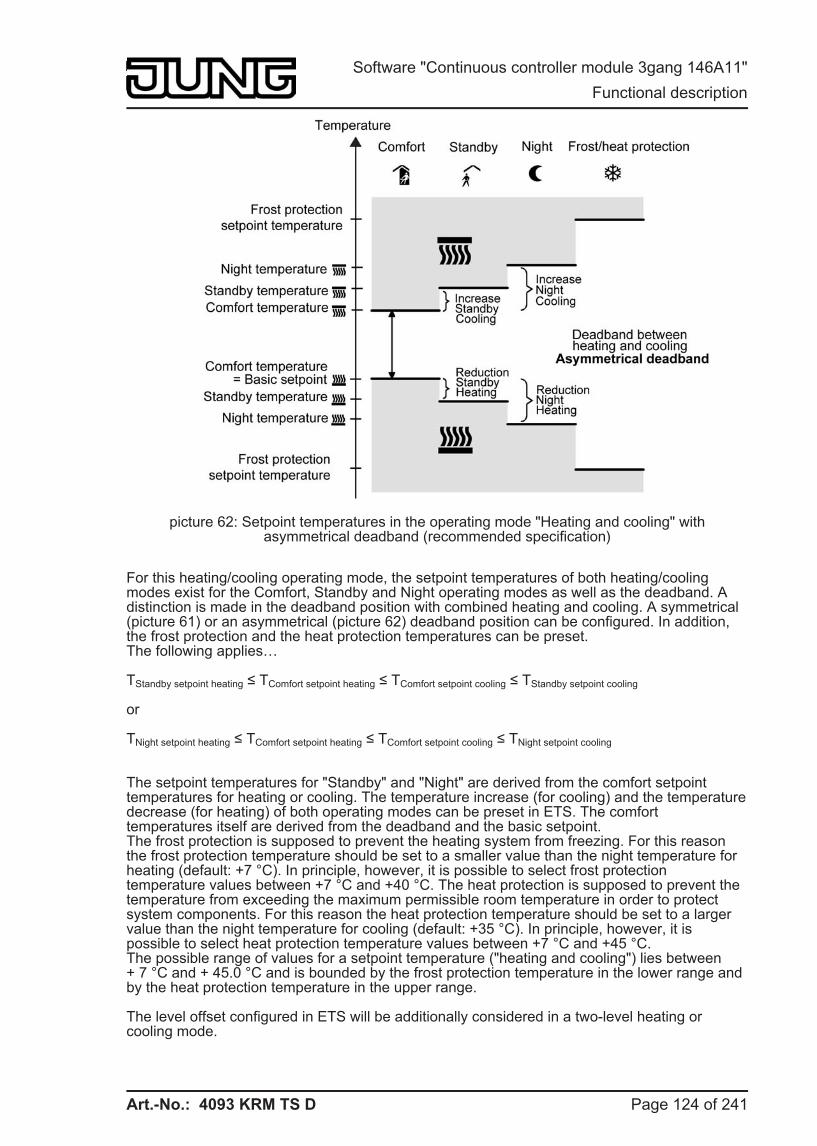
Art.-No.: 4093 KRM TS D
picture 62: Setpoint temperatures in the operating mode "Heating and cooling" with asymmetrical deadband (recommended specification)
For this heating/cooling operating mode, the setpoint temperatures of both heating/cooling modes exist for the Comfort, Standby and Night operating modes as well as the deadband. A distinction is made in the deadband position with combined heating and cooling. A symmetrical (picture 61) or an asymmetrical (picture 62) deadband position can be configured. In addition, the frost protection and the heat protection temperatures can be preset.The following applies…
TStandby setpoint heating ≤ TComfort setpoint heating ≤ TComfort setpoint cooling ≤ TStandby setpoint cooling
or
TNight setpoint heating ≤ TComfort setpoint heating ≤ TComfort setpoint cooling ≤ TNight setpoint cooling
The setpoint temperatures for "Standby" and "Night" are derived from the comfort setpoint temperatures for heating or cooling. The temperature increase (for cooling) and the temperature decrease (for heating) of both operating modes can be preset in ETS. The comfort temperatures itself are derived from the deadband and the basic setpoint.The frost protection is supposed to prevent the heating system from freezing. For this reason the frost protection temperature should be set to a smaller value than the night temperature for heating (default: +7 °C). In principle, however, it is possible to select frost protection temperature values between +7 °C and +40 °C. The heat protection is supposed to prevent the temperature from exceeding the maximum permissible room temperature in order to protect system components. For this reason the heat protection temperature should be set to a larger value than the night temperature for cooling (default: +35 °C). In principle, however, it is possible to select heat protection temperature values between +7 °C and +45 °C.The possible range of values for a setpoint temperature ("heating and cooling") lies between + 7 °C and + 45.0 °C and is bounded by the frost protection temperature in the lower range and by the heat protection temperature in the upper range.
The level offset configured in ETS will be additionally considered in a two-level heating or cooling mode.
Page 124 of 241
Software "Continuous controller module 3gang 146A11" Functional description
Art.-No.: 4093 KRM TS D
picture 63: Setpoint temperatures in the operating mode "Basic and additional heating and cooling" with symmetrical deadband (recommended specification)
picture 64: Setpoint temperatures in the operating mode "Basic and additional heating and cooling" with asymmetrical deadband (recommended specification)
Page 125 of 241
Software "Continuous controller module 3gang 146A11" Functional description
Art.-No.: 4093 KRM TS D
TComfort setpoint add. level Heating ≤ TComfort setpoint basic level Heating ≤ TComfort setpoint basic level Cooling ≤ TComfort setpoint add. level CoolingTStandby setpoint add. level Heating ≤ TStandby setpoint basic level Heating ≤ TStandby setpoint basic level Cooling ≤ TStandby setpoint add. level CoolingTStandby setpoint heating ≤ TComfort setpoint heating ≤ TComfort setpoint cooling ≤ TStandby setpoint cooling
or
TComfort setpoint add. level Heating ≤ TComfort setpoint basic level Heating ≤ TComfort setpoint basic level Cooling ≤ TComfort setpoint add. level CoolingTNight setpoint add. level Heating ≤ TNight setpoint basic level Heating ≤ TNight setpoint basic level Cooling ≤ TNight setpoint add. level CoolingTNight setpoint heating ≤ TComfort setpoint heating ≤ TComfort setpoint cooling ≤ TNight setpoint cooling
deadband and deadband positions in the combined heating and cooling operating mode
The comfort setpoint temperatures for heating and cooling are derived from the basic setpoint in consideration of the adjusted deadband. The deadband (temperature zone for which there is neither heating nor cooling) is the difference between the comfort setpoint temperatures.
The "deadband between heating and cooling", "deadband position" parameters as well as the "Basic temperature after reset" parameter are preset in the ETS configuration. One distinguishes between the following settings...
- deadband = "symmetrical"The deadband preset in the ETS is divided into two parts at the basic setpoint. The comfort setpoint temperatures are derived directly from the basic setpoint resulting from the half deadband.The following applies...TBasic setpoint – ½Tdeadband = TComfort heating setpoint
and
TBasic setpoint + ½Tdeadband = TComfort setpoint cooling-> TComfort cooling setpoint – TComfort heating setpoint = Tdeadband-> TComfort cooling setpoint ≥ TComfort heating setpoint
- deadband position = "Asymmetrical"With this setting the comfort setpoint temperature for heating equals the basic setpoint. The deadband preset in the ETS is effective only from the basic setpoint in the direction of comfort temperature for cooling. Thus the comfort setpoint temperature for cooling is derived directly from the comfort setpoint for heating.The following applies...TBasic setpoint = TComfort heating setpoint-> TBasic setpoint + Tdeadband = TComfort heating setpoint-> TComfort cooling setpoint – TComfort heating setpoint = Tdeadband-> TComfort cooling setpoint ≥ TComfort heating setpoint
Setpoint presettings in the ETS Temperature setpoints can be preset for each operating mode in the ETS as part of first configuration. It is possible to configure the setpoints for the "Comfort", "Standby" and "Night" modes in the ETS plug-in. If desired, the setpoint temperatures can be subsequently adjusted via local control during operation or controlled by KNX/EIB communication objects.The "Frost/heat protection" operating mode allows the separate configuration of two temperature setpoints for heating (frost protection) and cooling (heat protection) solely in the
Page 126 of 241
Software "Continuous controller module 3gang 146A11" Functional description
Art.-No.: 4093 KRM TS D
ETS. These temperature values cannot be changed later during controller operation.
When presetting the setpoint temperatures for comfort, standby and night mode, attention has to be paid to the fact that all setpoints depend on each other as all values are derived from the basic temperature (basic setpoint) (see chapter 4.2.4.2.5. Temperature setpoints). The "Basic temperature after reset" parameter in the "Setpoint" parameter page determines the basic setpoint, which is loaded when the device is programmed via the ETS. Taking into account the "Reduce / increase the setpoint temperature in standby mode" or "Reduce / increase the setpoint temperature in night mode" parameters the temperature setpoints for the standby and night mode are derived from this value depending on the heating or cooling operating mode. The deadband will be additionally considered for the "Heating and cooling"operating mode.In two-level control mode, all setpoint temperatures of the additional level are derived from the setpoint temperatures of the basic level. The setpoint temperatures of the additional level are determined by subtracting the "Difference between basic and additional levels", which is permanently configured in the ETS, from the setpoints of the basic level in heating mode or by adding the setpoints in cooling mode. If the temperature setpoints of the basic level are changed by setting a new basic setpoint, the setpoint temperatures of the additional level will be indirectly and automatically changed as well. Both levels will heat or cool with the same command value at the same time when the setpoint difference is "0".
Limitation of the setpoint temperatures in cooling mode In accordance with German statutory requirements, the temperature at the workplace should be a maximum of 26 °C, or at least 6 K below outdoor temperatures of 32 °C. Exceeding these limits is only permissible in exception circumstances. To meet these requirements, the room temperature controller offers a setpoint temperature limit, which is only effective in cooling mode. If necessary, the controller limits the setpoint temperature to specific values and prevents an adjustment beyond the limits.
The "Setpoint temperature limit in cooling mode" parameter in the "Room temperature controller -> Controller general -> Setpoint values" parameter node activates the limit and its function. The following settings are possible...
- Setting "Only difference to outdoor temperature"In this setting, the outdoor temperature is monitored and compare to the active setpoint temperature. The maximum temperature difference to the outdoor temperature can be specified in the range between 1 K and 15 K. The specification is made using the "Difference to outdoor temperature in cooling mode" parameter. The value can be set in levels of 1 K.If the outdoor temperature rises above 32 °C in the sense of the statutory requirements, then the controller activates the setpoint temperature limit. It then permanently monitors the outdoor temperature and raises the setpoint temperature so that is beneath the outdoor temperature by the amount configured. Should the outdoor temperature continue rise, the controller raises the setpoint temperature until the required difference to the outdoor temperature is achieved. It is then not possible to undershoot the raised setpoint, e.g. by changing the basic setpoint change.The change to the setpoint temperature limit is temporary. It only applies for as long as the outdoor temperature exceeds 32 °C.With the setpoint temperature limit, the configured temperature difference relates to the setpoint temperature of the Comfort mode for cooling. In other operating modes, the temperature distance to Comfort mode must be taken into account. Example...In the ETS, the difference to the outdoor temperature is set as 6 K. The Standby setpoint temperature is configured to 2 K higher than the Comfort setpoint temperature. The result of this is that, for command value limiting, the setpoint temperature in Standby operating mode may only be a maximum of 4 K below the outdoor temperature. The setpoint temperature limit applies to Night mode in the same way.
i The automatic setpoint temperature raising by the setpoint temperature limit goes only as far as the configured heat protection temperature. Therefore the heat protection temperature can never be exceeded.
Page 127 of 241
Software "Continuous controller module 3gang 146A11" Functional description
Art.-No.: 4093 KRM TS D
i A basic setpoint shift never affects an active setpoint temperature limit with differential measurement to the outdoor temperature. In this case, the setpoint temperature limit only works with the unshifted basic setpoint. A setpoint shift active before the limitation is restored after the limitation, if it was not reset in another way, e.g. by an operating mode change-over.
- Setting "Only max. setpoint temperature"In this setting, no setpoint temperatures are permitted in Cooling mode related to the Comfort, Standby and Night modes, which are greater than the maximum setpoints configured in the ETS. The maximum setpoint temperature is specified in the "Max. setpoint temperature in Cooling mode" parameter and be configured within the limits 20 °C to 35 °C in 1 °C levels.With an active limit, no larger setpoint can be set in cooling operation, e.g. by a basic setpoint change or a setpoint shift. However, heat protection is not influenced by the setpoint temperature limit.The maximum setpoint temperature configured in the ETS generally relates to the Comfort setpoint temperature of Cooling mode. In other operating modes, the temperature distance to Comfort mode must be taken into account. Example...The maximum setpoint temperature is configured to 26 °C. The Standby setpoint temperature is configured to 2 K higher than the Comfort setpoint temperature. The result of this is that, for command value limiting, the setpoint temperature in Standby operating mode is limited to 28 °C. The setpoint temperature limit applies to Night mode in the same way.
- Setting "Max. setpoint temperature and difference to outdoor temperature"This setting is a combination of the two above-mentioned settings. In the downward direction, the setpoint temperature is limited by the maximum outdoor temperature difference, whilst in the upward direction, the limit is made by the maximum setpoint.The maximum setpoint temperature has priority over the outdoor temperature difference. This means that the controller keeps on raising the setpoint temperature upwards according to the difference to the outdoor temperature configured in the ETS until the maximum setpoint temperature or the heat protection temperature is exceeded. Then the setpoint is limited to the maximum value.
i The setpoint display of the pushbutton sensor always shows the setpoint of the controller, taking the setpoint limit into account.
A setpoint limit enabled in the ETS can be activated or deactivated as necessary using a 1-bit object. For this, the "Activation of the setpoint temperature limit via object in cooling mode" parameter can be set to "Yes". In this case, the controller only takes the setpoint limit into account, if it has been enabled via the object "Cooling setpoint temp. limit" ("1" telegram). If the limitation is not enabled ("0" telegram), the cooling setpoint temperatures are not limited.After a device reset (bus voltage return, programming operation), the object value is "0", meaning that the setpoint limit is inactive.
i The setpoint limit has no function in Heating mode.
Adjusting the basic temperature / temperature for Comfort mode With the setpoint temperatures for Comfort, Standby and Night mode, attention has to be paid to the fact that all setpoints depend on each other as all values are derived from the basic temperature (basic setpoint). The "Basic temperature after reset" parameter in the "Room temperature measurement -> Controller general -> Setpoint" parameter page determines the basic setpoint which is loaded when the device is programmed via the ETS. The 2-byte object "Basic setpoint" provides the option of changing the basic temperature, and thus all the dependent setpoint temperatures 'at a later date'.
Page 128 of 241
Software "Continuous controller module 3gang 146A11" Functional description
Art.-No.: 4093 KRM TS D
A change via the object must always be enabled in the ETS by configuring the parameter "Change the basic temperature setpoint via bus" to "Approve". If the basic setpoint adjustment via the bus is disabled, the "Basic setpoint" object will be hidden (setting "deactivated").
i The pushbutton sensor automatically rounds off to 0.5 K the temperature values received via the "basic setpoint".
In addition or as an alternative, the basic setpoint can also be changed using local control in the second operating level of the pushbutton sensor. Here the basic setpoint sets the appropriate comfort temperature directly in the individual operating modes "Heating" or "Cooling". In the combined operating mode "Heating and cooling", the basic setpoint sets the comfort temperature for heating either directly (asymmetrical deadband) or indirectly (symmetrical deadband) according to the deadband positions configured in the ETS. The comfort setpoint temperature for cooling is then derived directly from the comfort setpoint for heating, taking the deadband into account.The adjustment option of the basic temperature in the second operating level must be enabled in the ETS. Local adjustment must be enabled using parameters in the parameter node "Room temperature control -> Controller general -> Second operating level".
i The size of the deadband and also the deadband position (symmetrical / asymmetrical) in "Heating and cooling" cannot be changed with local control in the second operating level.
One has to distinguish between two cases, defined by the "Apply change to basic temperature setpoint permanently" parameter, if the basic setpoint has been modified via local control or via the object...
- Case 1: The basic setpoint adjustment is permanently accepted ("Yes" setting):If, with this setting, the basic temperature setpoint is adjusted, the controller saves the value permanently to the EEPROM. Saving in this device memory takes place without a decimal point (e.g. basic setpoint value specification by object = 21.5 °C -> 21 °C saved)! The newly adjusted value will overwrite the basic temperature originally configured via the ETS after a reset! This is the only way to keep the adjusted basic setpoint even after change-over of the operating mode or after a reset.With this setting, it should be noted that frequent changing of the basic temperature (e.g. several times a day) can affect the product life of the device as the non-volatile storage (EEPROM) is designed for less frequent write access. In addition, the "Basic setpoint" object is not bidirectional, meaning that a basic setpoint changed by local control is not signalled back to the KNX/EIB. A previously saved basic setpoint remains active after the return of bus voltage, providing that the device was not programmed by the ETS.
- Case 2: The basic setpoint adjustment is only temporarily accepted ("No" setting):The basic setpoint, which was set on the room temperature controller or received via the object, stays only temporarily active in the current operating mode. In case of a bus voltage failure or following a change-over to another operating mode (e.g. Comfort followed by Standby), the basic setpoint set via local control or received via the object will be discarded and replaced by the value which was originally configured in the ETS.
i With local control in the second operating level, it must be taken into account that temperature changes that have been made are only saved to the device when this is provided for in the ETS configuration.
Page 129 of 241
Software "Continuous controller module 3gang 146A11" Functional description
Art.-No.: 4093 KRM TS D
Adjusting the temperatures for Standby and Night mode A basic setpoint change has an impact on the temperature setpoints for Standby and Night mode. Since the setpoint temperatures for the "Standby" and "Night" operating modes are derived from the Comfort setpoint temperature, the Standby and Night temperatures will shift in linear fashion by the change of the basic setpoint value. The shift takes place taking the increase or decrease values for Standby and Night mode either configured in the ETS or made indirectly locally into account.
In addition or alternatively to a basic setpoint change, it is possible, through local control on the pushbutton sensor in the second operating level, to set other temperature values for Standby and Night mode to those configured in the ETS. In this case, the originally configured decrease or increase values will be replaced by the new values resulting from the locally adjusted temperature setpoints. Independently of the "Accept modification of the basic temperature setpoint value permanently" parameter, the temperature setpoints for the standby or night mode will always be stored in the non-volatile EEPROM memory.Local adjustment must be enabled using parameters in the parameter node "Room temperature control -> Controller general -> Second operating level".
Basic setpoint shift In addition to the setting of individual temperature setpoints via the ETS, the user is able to shift the basic setpoint within a settable range anytime via the second operating level or via the basic setpoint object with the "Setpoint shift" push-button function, if this is configured to a function button of the pushbutton sensor. Each time a button is pressed, the basic setpoint is shifted upwards or downwards by one level (depending on the button operation and parameterisation). The shift is always performed in steps (not continuously when the button is held down). An adjustment by up to 4 steps is possible in this way.
A basic setpoint shift is shown at the lower edge of the display of the device by means of a line graphic "0 - - - -" (positive shift) or "- - - - 0" (negative shift). Each bar corresponds to shifting by one level value. The value of a level can be defined in the ETS using the parameter "Increment of the 4-level setpoint shift". If no shift is active, only "0" is displayed. The set temperature value is adopted immediately as the new setpoint when a function button is pressed, and is also shown in the display as an absolute temperature value, if this indication is parameterised in the ETS (see "Display function for basic setpoint shift" below).
i It has to be considered that a shift of the displayed setpoint temperature (temperature offset of the basic temperature) will directly affect the basic setpoint and as a result shift all other temperature setpoints.A positive shift is possible up to the configured heat protection temperature. A negative shift is possible up to the set frost protection temperature.
Page 130 of 241
Software "Continuous controller module 3gang 146A11" Functional description
Art.-No.: 4093 KRM TS D
Whether a basic setpoint shifting only affects the currently active operating mode or whether it influences all other set-temperatures of the remaining operating modes is determined by the "Accept modification of shift of basic setpoint value permanently" parameter in the "Room temperature control -> Controller general -> Setpoints" parameter page...
- "No" setting:The basic setpoint shifting carried out is in effect for only as long as the operating mode or heating/cooling mode has not changed or the basic setpoint is maintained. Otherwise the setpoint shift will be reset to "0".
- "Yes" setting:In general, the shifting of the basic setpoint carried out affects all operating modes. The shifting is maintained even after change-over of the operating mode or the heating/cooling mode or readjusting the basic setpoint.
i Since the value for the basic setpoint shift is stored exclusively in volatile memory (RAM), the shift will get lost in case of a reset (e.g. bus voltage failure).
i A setpoint shift does not affect the temperature setpoints for frost or heat protection!
Communication objects for the basic setpoint shift:
The controller tracks the current setpoint shift in the communication object "Acknowledge setpoint shift" via the controller with a 1-byte counter value (acc. to KNX DPT 6.010 – representation of positive and negative values in a double complement). By connecting to this object the controller extensions are also able to display the current setpoint shift. As soon as there is an adjustment by one temperature increment in positive direction, the controller counts up the value. The counter value will be counted down if there is a negative adjustment of the temperature. A value of "0" means that no setpoint shift has been adjusted.
Example:Starting situation: current setpoint temperature = 21.0 °C / increment = 0.5 K / counter value in "Acknowledge setpoint shift" = "0" (no active setpoint shift)After the setpoint shift:-> A setpoint shift by one temperature increment in the positive direction will count up the value in the "Acknowledge setpoint shift" object by one = "1".-> Current setpoint temperature = 21.5°C-> An additional setpoint shift by one temperature increment in the positive direction will again count up the value in the "Acknowledge setpoint shift" object by one = "2".-> Current setpoint temperature = 22.0°C-> A setpoint shift by one temperature increment in the negative direction will count down the value in the "Acknowledge setpoint shift" object by one = "1"-> Current setpoint temperature = 21.5°C-> An additional setpoint shift by one temperature increment in the negative direction will again count down the value in the "Acknowledge setpoint shift" object by one = "0"-> Current setpoint temperature = 21.0°C-> An additional setpoint shift by one temperature increment in the negative direction will again count down the value in the "Acknowledge setpoint shift" object by one = "-1"-> Current setpoint temperature = 20.5°C, etc. ...
In addition, the controller’s setpoint shift can be externally adjusted via the communication object "Preset setpoint shift". This object has the same data point type and range of values as the object "Acknowledge setpoint shift" (see above). By connecting to the "Setpoint shift specification" object the controller extensions are able to directly adjust the current setpoint shift of the controller. As soon as the controller receives a value, it will adjust the setpoint shift correspondingly. Values that lie within the possible value range of the basic setpoint shift can be directly jumped to. The controller monitors the received value independently. As soon as the external preset value exceeds the limits of the adjustment options for the setpoint shift in positive or negative direction, the controller will correct the received value and adjust the
Page 131 of 241
Software "Continuous controller module 3gang 146A11" Functional description
Art.-No.: 4093 KRM TS D
setpoint shift to maximum. Depending on the direction of the shift, the value feedback is set to the maximum value via the communication object "Acknowledge setpoint shift".
i The counter values are different for the increments configured in the ETS. An increment of 0.5 K counts the value in the object "Acknowledge setpoint shift" up (0, 1, 2, 3, 4) or down (0, -1, -2, -3, -4) by one digit. With an increment of 1.0 K the value is counted up (0, 2, 4, 6, 8) or down (0, -2, -4, -6, -8) in steps by two digits. The value of a counter value in the communication object is thus always 0.5 K. This procedure applies in the same manner for all other increments of the 4-level shift.In order for controller extensions to display correct shifts and also to activate the functions of the main controller correctly, it is necessary for the controller extension to be set to the same increment for the setpoint shift as the main controller (see chapter 4.2.4.3.1. Connection to room temperature controller)! Controller extensions that are not of identical types must work with an increment of 0.5 K!
Display function for basic setpoint shift:
Optionally the setpoint of the respective current operating mode can be shown automatically in the display if a setpoint shift is performed using the buttons of the device ("Setpoint shift" button function). The setpoint temperature is then displayed temporarily for 5 s in °C or °F, and overwrites the normal display (time, actual temperature, etc.).The setpoint display in the case of a setpoint shift can be activated by setting the "Show temporary setpoint in display when setpoint shift?" parameter. to "Yes". With the setting "No" the temporary display is inactive, meaning that in case of a setpoint shift only the line graphic "- - - - 0 - - - -" is activated, but the temperature value is not also displayed automatically.
Depending on the configuration in the ETS, the normal depiction of the display can show various display information with cyclical change or by button control, including the setpoint temperature. Therefore for a setpoint shift a distinction is made among the following cases... - The temporary setpoint display for setpoint shift is active. At the time the button is pressed
for a setpoint shift the setpoint temperature is not visible in the display via the cyclical change of the display information or via a previous "change in the display reading" button call-up.In this case the first button-press of the setpoint shift causes the setpoint temperature of the active operating mode to be displayed. Only another button-press will shift the temperature by one level. The setpoint remains visible in the display for 5 s. After that the display switches back to the normal display, if the button for the setpoint shift is not pressed another time. Additional button-presses shift the setpoint temperature value again and cause it to be visible in the display for another 5 seconds.
- The temporary setpoint display for setpoint shift is active. At the time the button is pressed for a setpoint shift the setpoint temperature is visible in the display via the cyclical change of the display information or via a previous "change in the display reading" button call-up.In this case the setpoint is shifted by one level immediately by the first button-press of the setpoint shift. The display of the setpoint is updated in the display and thus shows the shifted setpoint temperature. However, the setpoint only remains visible in the display for the configured time of the cyclical change. After that the display switches over to the next piece of display information, if the button for the setpoint shift is not pressed another time. Additional button-presses activate the temporary setpoint display and cause the setpoint temperature value to be visible in the display for at least another 5 seconds.
- The temporary setpoint display for setpoint shift is inactive. At the time the button is pressed for a setpoint shift the setpoint temperature is visible in the display via the cyclical change of the display information or via a previous "change in the display reading" button call-up.In this case the setpoint is shifted by one level immediately by the first button-press of the setpoint shift. The display of the setpoint is updated in the display and thus shows the shifted setpoint temperature. However, the setpoint only remains visible in the display for the configured time of the cyclical change. After that the display switches over to the next piece of display information. The setpoint shift is then only shown via the line graphic, and no longer as a temperature value, even in case of further button-presses.
Page 132 of 241
Software "Continuous controller module 3gang 146A11" Functional description
Art.-No.: 4093 KRM TS D
i No temporary setpoint display takes place if a setpoint shift is performed in the second operating level of the device or via the communication objects (e.g. via controller extensions).
Transmitting the setpoint temperature The setpoint temperature, which is given by the active operating mode or has been subsequently adjusted, can be actively transmitted onto the bus via the 2-byte "Set temperature" object. The "Transmission at setpoint temperature modification by..." parameter in the "Room temperature controller functions -> controller general -> setpoint values" parameter node determines the temperature value by which the setpoint has to change in order to have the setpoint temperature value transmitted automatically via the object. Temperature value changes between 0.1°C and 25.5 °C or 0.1 K and 25.5 K are possible. The setting "0" at this point will deactivate the automatic transmission of the setpoint temperature.
In addition, the setpoint can be transmitted cyclically. The "Cyclical transmission of setpoint temperature" parameter determines the cycle time (1 to 255 minutes). The value "0" will deactivate the periodical transmission of the setpoint temperature value. It has to be pointed out that with deactivated periodical transmission and deactivated automatic transmission, no setpoint temperature telegrams will be transmitted in case of a change.Setting the "Read" flag on the "Setpoint temperature" object makes it possible to read out the current setpoint. Following the return of bus voltage or after re-programming via the ETS, the object value will be initialised according to the current setpoint temperature value and actively transmitted to the bus.
Page 133 of 241
Software "Continuous controller module 3gang 146A11" Functional description
Art.-No.: 4093 KRM TS D
4.2.4.2.6 Room temperature measurement
Temperature detection measured value formation
The "Temperature detection" parameter in the "Room temperature measurement" parameter node specifies the sensors to detect the room temperature. The following settings are possible...
- "Internal sensor"The temperature sensor integrated in the room temperature controller is activated. Thus, the actual temperature value is determined only locally on the device. In this parameterisation the feedback control will start directly after a device reset.
- "External sensor"The actual temperature is determined solely via the external temperature sensor. The internal sensor is inactive. In this case, the external sensor must either be a KNX/EIB room thermostat coupled via the 2-byte object "External temperature sensor" or a controller extension with temperature detection.The room temperature controller can request the current temperature value cyclically. For this the parameter "Request time for external sensors..." must be set to a value > "0". The request interval can be configured within the limits of 1 minute to 255 minutes. After a device reset the room temperature controller will first wait for a valid temperature telegram until the feedback control starts and a command value or fan level, if applicable, is output.
- "Internal and external sensor"With this setting the internal as well as the external temperature sensor is active. The external sensor must either be a KNX/EIB room thermostat coupled via the 2-byte object "External temperature sensor" or a controller extension with temperature detection.The room temperature controller can request the current temperature value cyclically. For this the parameter "Request time for external sensors..." must be set to a value > "0". The request interval can be configured within the limits of 1 minute to 255 minutes. After a device reset the room temperature controller will first wait for a valid temperature telegram until the feedback control starts and a command value or fan level, if applicable, is output.When evaluating the internal and the external sensors, the real actual temperature is made up from the two measured temperature values. The weighting of the temperature values is defined by the "Creation of measuring value internal against external" parameter. Depending on the different locations of the sensors or a possible non-uniform heat distribution inside the room, it is thus possible to adjust the actual temperature measurement. Often, those temperature sensors that are subject to negative external influences (for example, unfavourable location because of exposure to sun or heater or door / window directly next to it) are weighted less heavily.
Example: a room temperature controller is installed next to the entrance to the room (internal sensor). An additional external temperature sensor has been mounted on an inner wall in the middle of the room below the ceiling.Internal sensor: 21.5 °CExternal sensor: 22.3 °CDetermination of measured value: 30 % to 70 %
-> TResult internal = T internal · 0.3 = 6.45 °C,-> TResult external = Texternal = 22.3 °C · 0.7 = 15.61 °C-> TResult actual = TResult internal + TResult external = 22.06 °C
Calibrating the measured values In some cases during room temperature measurement, it may be necessary to adjust the temperature values of the internal and the external sensor. Adjustment becomes necessary, for example, if the temperature measured by the sensors stays permanently below or above the actual temperature in the vicinity of the sensor. To determine the temperature deviation, the
Page 134 of 241
Software "Continuous controller module 3gang 146A11" Functional description
Art.-No.: 4093 KRM TS D
actual room temperature should be detected with a reference measurement using a calibrated temperature measuring device.The parameter "Internal sensor adjustment..." and/or "External sensor adjustment..." in the "Room temperature measurement" parameter node can be used to configure the positive (temperature increase, factors: 1 ... 127) or a negative (temperature decrease, factors: –128 ... –1) temperature calibration in levels of 0.1 K. Thus, the calibration is made only once statically and is the same for all operating modes of the controller.
i The measured value has to be increased, if the value measured by the sensor lies below the actual room temperature. The measured value has to be decreased, if the value measured by the sensor lies above the actual room temperature.
i During room temperature control, the controller always uses the adjusted temperature value to calculate the command values. The adjusted temperature value is transmitted to the bus via the "Actual temperature" object (see "Transmission of the actual temperature").When determining the measured value using the internal and external sensor, the two adjusted values are used to calculate the actual value.If necessary, the unadjusted room temperature of the internal temperature sensor can additionally be transmitted to the bus as an information value (object "Actual temperature, unadjusted") and, for example, be evaluated in other bus devices or displayed in visualisations.
i Temperature adjustment only affects the room temperature measurement.
Transmission of the actual temperature The determined actual temperature can be actively transmitted to the bus via the 2-byte "Actual temperature" object. The parameter "Transmission when room temperature change by..." in the "Room temperature control" parameter node specifies the temperature value by which the actual value has to change in order to have the actual temperature value transmitted automatically via the object. Possible temperature value changes lie within a range of 0.1 K and 25.5 K. Setting to "0" at this point will deactivate the automatic transmission of the actual temperature.
In addition, the actual value can be transmitted periodically. The "Cyclical transmission of the room temperature" parameter determines the cycle time (1 to 255 minutes). The value "0" will deactivate the periodical transmission of the actual temperature value.Setting the "Read" flag on the "actual temperature" object makes it possible to read out the current actual value at any time over the bus. It has to be pointed out that with deactivated periodical transmission and deactivated automatic transmission, no more actual temperature telegrams will be transmitted in case of a change.
Following the return of bus voltage, new programming via the ETS, the object value will be updated according to the actual temperature value and transmitted on the bus. In case a temperature value telegram has not been received from the external sensor via the object "External temperature sensor" when evaluating an external temperature sensor, only the value provided by the internal sensor will be transmitted. If only the external sensor is used, then the value "0" is located in the "Actual temperature" object after a reset. For this reason, the external temperature sensor should always transmit the current value after a reset.
During room temperature control, the controller always uses the adjusted temperature value to calculate the command values. The adjusted temperature value is transmitted to the bus via the "Actual temperature" object. If necessary, the unadjusted room temperature can additionally be transmitted to the bus as an information value via the object "Actual temperature, unadjusted" and, for example, be displayed in visualisations. The object for the unadjusted temperature is updated and transmitted at the same times as the "Actual temperature" object.
Page 135 of 241
Software "Continuous controller module 3gang 146A11" Functional description
Art.-No.: 4093 KRM TS D
Underfloor heating temperature limit The temperature limit can be activated in the controller in order to protect an underfloor heating system. If the temperature limit is enabled in the ETS, the controller continuously monitors the floor temperature. Should the floor temperature exceed a specific limiting value on heating, the controller immediately switches the command value off, thus switching the heating off and cooling the system. Only when the temperature falls below the limiting value, minus a hysteresis of 1 K, will the controller add the most recently calculated command value.
In the ETS, the temperature limit can be activated by setting the "Underfloor heating temperature limit available" parameter in the "Room temperature controller -> Controller functionality" parameter node to "Present".
i It should be noted that the temperature limit only affects command values for heating. Thus, the temperature limit requires the controller operating modes "Heating" or "Heating and cooling" (see chapter 4.2.4.2.1. Operating modes and operating mode change-over). The temperature limit cannot be configured in the operating mode "Cooling".
The temperature limit can also be used in a two-level feedback control with basic and additional levels. However, it must then be specified in the ETS to which level the limit shall apply. The limit can then either apply to the basic level or to the additional level for heating using the "Affects" parameter. The underfloor heating temperature to be monitored can be fed into the controller via the KNX/EIB communication object "Floor temperature". As soon as the temperature limit is enabled in the ETS, the 2-byte object "Floor temperature" becomes visible. This object can be used to inform the controller of the current floor temperature using suitable temperature value telegrams from other bus devices (e.g. analogue input with temperature sensor, etc.). The maximum limit temperature, which the underfloor heating system may reach, is specified in the ETS using the "Maximum underfloor heating system temperature" parameter. The temperature can be set to a value between 20 and 70 °C. If this temperature is exceeded, the controller switches the underfloor heating system off using the command value. As soon as the floor temperature has fallen 1 K under the limit temperature, the controller switches the command value on again, assuming that this is intended in the control algorithm. The 1 K hysteresis is fixed and cannot be changed.
i Depending on the configuration, the temperature may have a strong impact on the controller behaviour. Poor parameterisation of the limit temperature (limit temperature near to the room/setpoint temperature) means that it is possible that the specified setpoint temperature for the room can never be reached!
Page 136 of 241
Software "Continuous controller module 3gang 146A11" Functional description
Art.-No.: 4093 KRM TS D
4.2.4.2.7 Command value and status output
Command value objects The format of the command value objects are determined depending on the control algorithm selected for heating and / or cooling and, if applicable, also for the additional levels. 1 bit or 1 byte command value objects can be created in the ETS. The control algorithm calculates the command values in intervals of 30 seconds and outputs them via the objects. With the pulse width modulated PI feedback control (PWM) the command value is updated, if required, solely at the end of a time cycle.
Possible object data formats for the command values separately for both heating/cooling operating modes, for the basic and the additional level or for both control circuits are… - Continuous PI feedback control: 1 byte - Switching PI feedback control: 1 bit + additionally 1 byte (for example for the status
indication with visualisations), - Switching 2-point feedback control: 1 bit.
Depending on the selected heating/cooling operating mode, the controller is able to address heating and / or cooling systems, to determine command values and to output them via separate objects. One distinguishes between two cases for the "Heating and cooling" mixed operating mode...
- Case 1: Heating and cooling system are two separate systemsIn this case the "Transmit heating and cooling command value to one common object" parameter should be set to "No" in the "Room temperature controller -> Controller functions" parameter node. Thus, there are separate objects available for each command value, which can be separately addressed via the individual systems.This setting allows to define separate types of control for heating and cooling.
- Case 2: Heating and cooling system are a combined systemIn this case the "Transmit heating and cooling command value to one common object" parameter may be set, if required, to "Yes". This will transmit the command values for heating and cooling to the same object. In case of a two-level feedback control, another shared object will be enabled for the additional levels for heating and cooling.With this setting it is only possible to define the same type of feedback control for heating and for cooling as the feedback control and the data format must be identical. The ("Type of heating / cooling") control parameter for cooling and heating still has to be defined separately.A combined command value object may be required, for example, if heating as well as cooling shall take place via a single-pipe system (combined heating and cooling system). For this, the temperature of the medium in the single-pipe system must be changed via the system control. Afterwards the heating/cooling operating mode is set via the object (often the single-pipe system uses cold water for cooling during the summer, hot water for heating during the winter).
If required, the command value can be inverted before the transmission to the KNX/EIB. With output via a combined object, the parameters "Output of heating command value", "Output of cooling command value" or "Output of command values..." output the command value in inverted fashion according to the object data format. The parameters for inverting the additional level(s) are additionally available in the two-level control.
The following applies…For continuous command values:-> Not inverted: Command value 0 % ... 100 %, value 0 ... 255-> Inverted: Command value 0 % ... 100 %, value 255 ... 0For switching command values:-> Not inverted: Command value off / on, value 0 / 1-> Inverted: Command value off / on, value 1 / 0
Page 137 of 241
Software "Continuous controller module 3gang 146A11" Functional description
Art.-No.: 4093 KRM TS D
Automatic transmission
On automatic transmission, a distinction is made with regard to the type of control...
- Continuous PI feedback control:In case of a continuous PI feedback control, the room temperature controller calculates a new command value periodically every 30 seconds and outputs it to the bus via a 1-byte value object. The change interval of the command value can be determined in percent according to which a new command value is to be output on the bus via the "Automatic transmission on change by..." parameter in the "Room temperature controller -> Controller general -> Command values and status output" parameter node. The change interval can be configured to "0" so that a change in the command value will not result in an automatic transmission.In addition to the command value output following a change, the current command value may be periodically transmitted on the bus. In addition to the times when changes are to be expected, other command value telegrams will be output according to the active value after a configurable cycle time. This ensures that during a periodic access control of the command value in servo drive or in the addressed switching actuator, telegrams are received within the control interval. The time interval predetermined by the "Cycle time for automatic transmission..." parameter should correspond to the control interval in the actuator (cycle time in the controller is preferably to be configured smaller). The "0" setting will deactivate the periodic transmission of the command value.With continuous PI feedback control it must be noted that if the cyclical and the automatic transmission are both deactivated, no command value telegrams will be transmitted in case of a change!
- Switching PI feedback control (PWM):In case of a switching PI feedback control (PWM), the room temperature controller calculates a new command value internally every 30 seconds. In this feedback control, however, the update of the command value takes place, if required, solely at the end of a PWM cycle. The parameters "automatic transmission on change by..." and "Cycle time for automatic transmission..." are not enabled with this control algorithm. The parameter "Cycle time of the switching command value..." defines the cycle time of the PWM command value signal.
- 2-point feedback control:In case of a 2-point feedback control, the room temperature and thus the hysteresis values are evaluated periodically every 30 seconds, so that the command values, if required, will change solely during these times. The "Automatic transmission on change by..." parameter is not enabled as this control algorithm does not calculate continuous command values.In addition to the command value output following a change, the current command value may be periodically transmitted on the bus. In addition to the times when changes are to be expected, other command value telegrams will be output according to the active value after a configurable cycle time. This ensures that during a periodic access control of the command value in servo drive or in the addressed switching actuator, telegrams are received within the control interval. The time interval predetermined by the "Cycle time for automatic transmission..." parameter should correspond to the control interval in the actuator (cycle time in the controller is preferably to be configured smaller). The "0" setting will deactivate the periodic transmission of the command value.
Page 138 of 241
Software "Continuous controller module 3gang 146A11" Functional description
Art.-No.: 4093 KRM TS D
Controller status
The room temperature controller can transmit its current status to the KNX/EIB. For this purpose, an optional collective status signal (1 byte type) or, alternatively, one of up to eight single status signals (1 bit type) are available. The "Controller status" parameter in the "Room temperature controller -> Controller general -> Command value and status output" parameter branch will enable the status signal and set the status format...
- "Controller status" = "Controller general":The 1-byte "Controller status" object contains the entire status information (see Table 8). The status will be actively transmitted to the bus in cycles every 30 seconds (provided that the "Transmission" flag has been set), but only on changes. The status can be read out by setting the "Read" flag.
Bit of the status telegram Meaning 0 On "1": Comfort operation activated 1 On "1": Standby mode active 2 On "1": Night mode active 3 On "1": Frost/heat protection mode active 4 On "1": Controller disabled 5 On "1": Heating, on "0": Cooling 6 On "1": Controller inactive (deadband) 7 On "1": Frost alarm (TRoom ≤ +5 °C)
Table 8: Bit encoding of the 1 byte status telegram
- "Status indication of controller" = "Transmit individual state":The 1 bit status object "Controller status, ..." contains the status information selected by the "Single status" parameter (see Table 9). The status will be actively transmitted to the bus in cycles every 30 seconds (provided that the "Transmission" flag has been set), but only on changes. The status can be read out by setting the "Read" flag.
Parameterisation for"Single status"
Meaning on "1" Meaning on "0"
Comfort mode activated Comfort mode /extension active
No comfort mode
Standby mode activated Standby mode activated No standby mode Night mode activated Night mode activated No night mode Frost/heat protection active Frost/heat protection active No frost/heat protection Controller disabled Controller disabled
(dew point operation) Controller not disabled
Heating / cooling Heating mode Cooling mode Controller inactive Controller inactive (deadband) Controller active Frost alarm Frost alarm
(TRoom ≤ +5 °C) No frost alarm(TRoom > +5 °C / +41 °F)
Table 9: Meaning of the 1-bit single status signals
Page 139 of 241
Software "Continuous controller module 3gang 146A11" Functional description
Art.-No.: 4093 KRM TS D
Meaning of the status signals:
Comfort-mode -> Is active if operating mode "Comfort ó " or a comfort extension "óõ" or "óö" is activated. Standby -> Is active if the "Standby ô" operating mode is activated.Night-mode -> Is active if the "Night õ" operating mode is activated.Frost/heat protection -> Is active if the "Frost/heat protection ö" operating mode is activated.Controller disabled -> Is active if controller disable is activated ÷ (dew point mode).Heating / cooling -> Is active if heating is activated and inactive if cooling is activated. Inactive if controller is disabled.Controller inactive -> Is active in the "Heating and cooling" operating mode when the measured room temperature lies within the deadband. This status information is always "0" for the individual "Heating" or "Cooling" operating modes. Inactive if controller is disabled.Frost alarm -> Is active if the detected room temperature reaches or drops below +5 °C or +41 °F. This status signal will have no special influence on the control behaviour.
i Upon a reset, status object will be updated after the initialisation phase. After this, the status will be updated cyclically every 30 seconds in parallel with the command value calculation of the controller command values.
Additional controller status The additional controller status is a 1-byte object, in whose value various information is collected in orientated to bits. In this way, controller statuses, which are not available via the 'normal' 1-bit or 1-byte controller status, can be displayed on other KNX/EIB devices or processed further (see Table 10). For example, controller extensions can evaluate the additional status information, in order to be able to display all the necessary controller status information on the extension display.The 1-byte object "Status signal addition" is a pure visualisation object, which cannot be written.
Bit of the status telegram
Meaning on "1" Meaning on "0"
0 Normal operating mode Forced operating mode 1 Comfort extension active No comfort extension 2 Presence (Motion detector) No presence
(Motion detector) 3 Presence (Presence button) No presence
(Presence button) 4 Window opened No window opened 5 Additional level active Additional level inactive 6 Heat protection active Heat protection inactive 7 Controller disabled
(dew point operation) Controller not disabled
Table 10: Bit encoding of the 1 byte additional status telegram i Upon a reset, the additional status object will be updated after the initialisation phase. After
this, the status will be updated cyclically every 30 seconds in parallel with the command value calculation of the controller command values.
Page 140 of 241
Software "Continuous controller module 3gang 146A11" Functional description
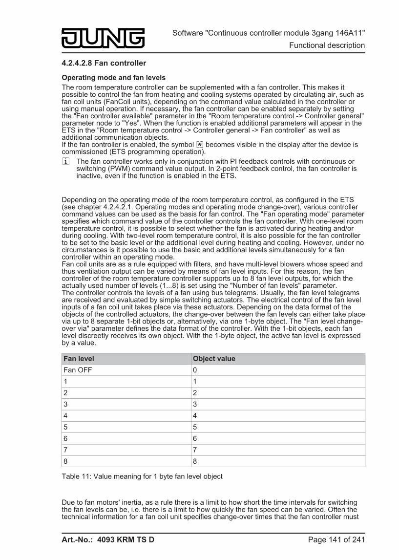
Art.-No.: 4093 KRM TS D
4.2.4.2.8 Fan controller
Operating mode and fan levels The room temperature controller can be supplemented with a fan controller. This makes it possible to control the fan from heating and cooling systems operated by circulating air, such as fan coil units (FanCoil units), depending on the command value calculated in the controller or using manual operation. If necessary, the fan controller can be enabled separately by setting the "Fan controller available" parameter in the "Room temperature control -> Controller general" parameter node to "Yes". When the function is enabled additional parameters will appear in the ETS in the "Room temperature control -> Controller general -> Fan controller" as well as additional communication objects.If the fan controller is enabled, the symbol ë becomes visible in the display after the device is commissioned (ETS programming operation). i The fan controller works only in conjunction with PI feedback controls with continuous or
switching (PWM) command value output. In 2-point feedback control, the fan controller is inactive, even if the function is enabled in the ETS.
Depending on the operating mode of the room temperature control, as configured in the ETS (see chapter 4.2.4.2.1. Operating modes and operating mode change-over), various controller command values can be used as the basis for fan control. The "Fan operating mode" parameter specifies which command value of the controller controls the fan controller. With one-level room temperature control, it is possible to select whether the fan is activated during heating and/or during cooling. With two-level room temperature control, it is also possible for the fan controller to be set to the basic level or the additional level during heating and cooling. However, under no circumstances is it possible to use the basic and additional levels simultaneously for a fan controller within an operating mode.Fan coil units are as a rule equipped with filters, and have multi-level blowers whose speed and thus ventilation output can be varied by means of fan level inputs. For this reason, the fan controller of the room temperature controller supports up to 8 fan level outputs, for which the actually used number of levels (1...8) is set using the "Number of fan levels" parameter.The controller controls the levels of a fan using bus telegrams. Usually, the fan level telegrams are received and evaluated by simple switching actuators. The electrical control of the fan level inputs of a fan coil unit takes place via these actuators. Depending on the data format of the objects of the controlled actuators, the change-over between the fan levels can either take place via up to 8 separate 1-bit objects or, alternatively, via one 1-byte object. The "Fan level change-over via" parameter defines the data format of the controller. With the 1-bit objects, each fan level discreetly receives its own object. With the 1-byte object, the active fan level is expressed by a value.
Fan level Object value Fan OFF 0 1 1 2 2 3 3 4 4 5 5 6 6 7 7 8 8
Table 11: Value meaning for 1 byte fan level object
Due to fan motors' inertia, as a rule there is a limit to how short the time intervals for switching the fan levels can be, i.e. there is a limit to how quickly the fan speed can be varied. Often the technical information for a fan coil unit specifies change-over times that the fan controller must
Page 141 of 241
Software "Continuous controller module 3gang 146A11" Functional description
Art.-No.: 4093 KRM TS D
maintain for each fan level change-over. The change-over direction, i.e. whether the level is being increased or decreased, does not play any role here.With a change-over via the 1-bit objects, when the fan level is changed by the controller, the active fan level is first switched off before the new level is switched on. If the fan controller is working in automatic mode, the settable "Waiting time on level change-over" is maintained on change-over of the levels. For this short time, the fan level objects all receive the status "0 - Fan off". A new level is only then switched on when the waiting time has elapsed. Only one fan level output is ever switched on (changeover principle).With change-over via the 1-byte object, on changing the fan level, the change-over takes place directly into the new level, without setting the "OFF" status. If the fan controller is working in automatic mode, the settable "Waiting time on level change-over" (dwell time) is always taken into account before change-over of the levels. With rapid level change-over, the change to the new level only takes place once the waiting time has elapsed.
i The change from level 1 to OFF always takes place immediately, without a waiting time. An optionally-configured switch-on level is applied directly.
i In manual mode, the "Waiting time on level change-over" is only significant for the switch-on level (Start-up via level). Here, the fan levels can be switched over without a delay through manual operation.
i When changing from manual operation to automatic operation, the waiting time is taken into account in the case of a connected level change.
The fan level active in the current controller operating state is shown with using the fan symbol in the display of the device. In both automatic and manual operation (for a function description, please see the section "Automatic operation / manual operation"), the display takes place via arc segments in the fan symbol in the following manner...ë Fan OFFì Fan level 1 activeí Fan level 2 activeî Fan level 3 activeï Fan level 4 activeð Fan level 5 activeñ Fan level 6 activeò Fan level 7 activeê Fan level 8 active
With up to 8 fan levels each individual fan level is identified in the fan symbol by an individual arc segment. The arc is closed when all 8 fan levels are switched on.If the number of fan levels is reduced in the ETS (e.g. "3"), adjacent arc segments are joined into groups, so that when the largest fan level ("3" - ê) is activated, all of the arc segments of the fan symbol are illuminated. For smaller fan levels, fewer group segments are illuminated in like manner ("2" - ñ / "1" - î).
i The fans of a fan coil unit are - as described above - controlled by the fan level objects of the controller. The electromechanical valves for heating and/or cooling, integrated into the blower devices, can be controlled via suitable switching actuators using the objects "Heating message" or "Cooling message" (see page 100).
i The 1-byte object "Ventilation visualisation" can, if necessary, also be evaluated by other bus devices (e.g. visualisation - panel / PC software). It always transmit the current fan level as a 1-byte value, either automatically on a change or passively on reading out (value explanation according to Table 11).
i The objects of the fan levels are only updated by the controller. These objects may not be written to by other bus subscribers. Reading out is possible.
i After a device reset, the fan level objects and the visualisation object are updated and the status transmitted to the bus.
Page 142 of 241
Software "Continuous controller module 3gang 146A11" Functional description
Art.-No.: 4093 KRM TS D
Automatic operation / manual operation The fan controller distinguishes between automatic and manual operation. The change-over between the two operating modes takes place using the 1-bit object "Ventilation, auto/manual", through the operation of a button on the device configured for "Fan control", or in the second operating level locally on the device. In manual operation the Ü symbol is illuminated in the display.The parameter "Interpretation object fan control automatic/manual" in the fan control parameter group defines with which switching value the automatic or manual operation is set via the communication object. Automatic mode is always active after a device reset.
i The "Ventilation, auto/manual" object transmits actively ("Transmit" flag set). When the operating mode is changed over using local control, the valid status is transmitted to the bus.
i Updates to the object value "Automatic mode active" -> "Automatic mode active" or "Manual mode active" -> "Manual mode active" do not produce any reaction.
Automatic mode:The command value of the controller is used internally in the device for automatic control of the fan levels. As a transition between the levels, there are threshold values, defined according to the command value of the controller, which can be set using parameters in the ETS. If the command value exceeds the threshold value of a level, the appropriate level is activated. If the command value sinks below a threshold value, minus the configured hysteresis, then the change-over takes place into the next lowest fan level. The hysteresis value applies to all the threshold values.The threshold values for the individual fan levels can be parameterised freely in the range from 1 ... 99%. The threshold values are not checked for plausibility in the ETS, meaning that incorrect parameterisation is possible. For this reason, it must be ensured that the threshold values, compared to the level value, are configured in a rising direction (level 1 threshold value > level 2 threshold value > level 3 threshold value > etc.).When the command value changes, and thus the fan level, it is only possible to switch directly into neighbouring levels (exception: switch-on level). Thus, in Automatic operation, it is only possible, for example, to switch from level 2 down to level 1 or up to level 3. If the command value change exceeds or undershoots the threshold values of multiple fan levels, then, starting with the current fan level, all the fan levels are activated in succession until the fan level specified by the command value is reached.If the fan is switched off by the automatic system, then it runs on for the time configured as "Fan run-on time, heating" or "Fan run-on time, cooling", providing that these run-on times are configured in the ETS.
i In automatic mode, the fan level objects are updated according to the internal command value calculation (cyclically every 30 seconds) plus the waiting time configured for level change-over. Telegram transmission only takes place when the object values of the fan levels are changed. After a device reset, the fan level objects are updated and the status transmitted to the bus.
i If a switch-on level is configured in the ETS ("Start-up via level" parameter), then, before the automatic activation of a fan level, it is possible to switch to a level, specified in the ETS and usually higher, for a brief time according to the command value (see section "Switch-on level").
i The command value evaluated by the fan controller in Automatic mode can be optionally limited by in the top and bottom command value ranges by the parameters "Command value is 0% until internal command value is greater than" and "Command value is 100% as soon as internal command value is greater than". In addition, the command value can also be raised by a constant value by the "Command value offset" parameter (see page 146-147).
Manual operation:With the local control of a button configured to "Function = Fan control" and "Button function = Manual control" on the device, the controller makes a distinction as to
Page 143 of 241
Software "Continuous controller module 3gang 146A11" Functional description
Art.-No.: 4093 KRM TS D
whether it was in automatic or manual mode at the time the button was pressed.If the controller is in automatic mode, then pressing a button switches to manual mode. The parameter "Fan level on change-over to manual" then decides whether the fan level most recently set in automatic mode is maintained, the fan is switched off or a defined fan level is set (see also next section "Switch-on level").If, at the time the button is pressed, the manual controller is already active, then the controller switches to the next highest fan level without a delay. If the fan is in the highest level, then pressing a button switches it back to the OFF level. From there, every additional press causes the fan level to be raised. The switch-on level is ignored.If the fan is switched off manually from the highest level, then it runs on for the time configured as "Fan run-on time, heating" or "Fan run-on time, cooling", providing that these run-on times are configured in the ETS. If, during the run-on time, the manual control button is pressed again, the controller will terminate the run-on time. The fan switches off briefly and then switches immediately to level 1.
In fan control in the second operating level the fan level and automatic mode can be set directly without taking into account the parameter "Fan level on change-over to manual", the switch-on level or fan run-on times (see chapter 2.5.2. Second operating level).
i The 1-bit object "Ventilation, auto/manual" only allows change-over between automatic and manual operation. It is not possible to switch the fan levels on using the object. This function is reserved solely for local control.
i Local actuation of a button configured to "Function = Fan control" and "Button function = Automatic" on the device deactivates manual operation and causes the controller to change over to automatic operation.
i When changing from manual operation to automatic operation, the waiting time configured in the ETS is taken into account in the case of a connected level change.
i The parameter "Fan level on change-over to manual" is not checked for plausibility in the ETS, meaning that an implausible parameterisation is possible. For this reason, care should be taken to ensure that there is no level in the configuration which is higher than the actual fan levels. If a level which does not exist is to be configured for the change-over to manual control, then the fan controller changes over to the maximum possible level when changing over to manual operation.
i In manual operation, the switch-on level only functions in certain situations (see next section "Switch-on level").
Switch-on level The fan can, if it was switched off before and should now start up, be switched on at a defined switch-on level. This switch-on level can be any of the available fan levels, and is set in the ETS using the "Start-up via level" parameter. The switch-on level is generally one of the higher fan levels of a fan coil unit, so that at the beginning of a heating or cooling process the fan can start up correctly (reliable start-up of the fan motor through transfer of a higher torque, and thus a higher fan speed).The switch-on level remains active for the "Waiting time on level change-over" configured in the ETS. In automatic operation, the controller only switches to the fan level specified by the command value, when the waiting time has elapsed. There is no change-over if, after the waiting time has elapsed, the fan level specified by the command value equals the switch-on level.
i If the controlled fan requires a longer period of time for the start-up, then the waiting time in the ETS should be configured to higher values (possible time range 100 ms ... 25.5 s). It should be noted that the waiting time is also taken into account on each level change-over in automatic operation (see page 141-142).
Page 144 of 241
Software "Continuous controller module 3gang 146A11" Functional description
Art.-No.: 4093 KRM TS D
The switch-on level is always taken into account by the fan controller in automatic mode on switching the fan on (if it was previously switched off by the command value evaluation) and, in certain situations, after activation of manual operation. On changing over to manual operation, the behaviour of the fan depends on the settings of the parameter "Fan level on changing over to manual" and "Start-up via level" and the previous fan level in automatic operation as follows...
- If, due to the "Fan level on change-over to manual" parameter, a defined level from level 1 to level 8 is requested, the controller will set this level on activating manual operation. In this case, the parameter "Start-up via level" is not taken into account if the fan was most recently switched off in automatic operation.
- If, due to the "Fan level on change-over to manual" parameter, "Fan level OFF" is requested, the controller will switch the fan off during the change-over to manual operation. On subsequent pressing of the button for manual control, the "Start-up via level" parameter is taken into account and the switch-on level set. Then, the controller waits in this level until further manual operation.
- If, due to the "Fan level on change-over to manual" parameter, no defined level is requested ("No change" setting) and the fan was switched off during automatic operation, then it will remain switched off on changing over to manual operation. On subsequent pressing of the button for manual control, the fan is switched to the first level. The "Start-up via level" parameter is thus not taken into account.
i A configured switch-on level is applied directly without a waiting time. i With a fan change-over via the 1-bit objects, when the fan level is changed by the
controller, the active fan level is first switched off before the new level is switched on. In this case, the switch-off of a fan level and the subsequent changeover to a new fan level is not evaluated as a fan start-up, also meaning that the switch-on level is not set In automatic operation, the switch-on level is only taken into account if the fan was switched off previously by the command value evaluation (command value < level 1 threshold value minus hysteresis) and then it is to start up using a new command value.
i The start-up via the switch-on level also takes place after a change-over from manual operation to automatic operation, providing that the fan was most recently switched off in manual operation and, in automatic operation, a new command value requires the fan to be switched on.
i The parameter "Start-up via level" is not checked for plausibility in the ETS, meaning that an implausible parameterisation is possible. For this reason, care should be taken to ensure that there is no switch-on level in the configuration which is higher than the actual fan levels. The fan controller automatically corrects a faulty parameterisation by activating level 1 for the start-up, meaning that the fan starts up normally without a switch-on level.
Fan level limit To reduce the fan noise of a fan coil, the fan level limit can be activated. The level limit reduces the sound emissions by limiting the maximum fan level to a fan level value specified in the ETS by the "Level limit" parameter (limit level). The limitation can be switched on and off via a 1-bit "Fan, level limit" object, and thus activated in accordance with requirements, for example via a timer during night-time hours in order to reduce noise in bedrooms, or via "manual" operation of a pushbutton when a "quiet room" is needed (auditorium or the like). The limitation of the fan level is activated by receipt of a "1" telegram via the object "Fan, level limitation". Deactivation is therefore achieved through the receipt of a "0" telegram.While a limitation is active, the fan controller prevents the fan from being switched to a higher level than the limitation level. If, at the instant that the limit is activated, the fan is running at a level that is greater than the limit level, then the fan level is immediately reduced to the limitation value. In this case the switching sequence of the individual levels and the waiting time configured in the ETS are also taken into account in the level change-over.The limitation level can be one of the available fan levels.
Page 145 of 241
Software "Continuous controller module 3gang 146A11" Functional description
Art.-No.: 4093 KRM TS D
The level controller distinguishes between Automatic and Manual operation.
i The fan level limit overdrives the switch-on level. As a result, when the fan is switched on, if the limit is active, the level has an active limit and the switch-on limit is not started. In this case, the limit level is jumped to without waiting.
i The level limit has no effect with an activated fan forced position. i The parameter "Level limit" is not checked for plausibility in the ETS, meaning that an
implausible parameterisation is possible. For this reason, care should be taken to ensure that there is no limit level in the configuration which is higher than the actual fan levels. If a higher limit level is configured, then the limit has no effect.
Forced fan position The controller provides the option of activating a forced fan position via the bus. With an active forced position, the fan levels can neither be controlled nor switched over in either automatic or manual mode. The fan remains in the forced state until the forced position is removed using the bus. In this manner, it is possible to switch the fan to a locked and controlled state, for example for servicing purposes.As soon as a "1" telegram is received via the 1-bit object "Ventilation, forced position", the controller immediately sets the fan level configured in the ETS without delay. The fan can also be completely switched off. The only special feature when activating the forced position is the fact that the fan controller is in automatic operation and a waiting time elapses, due to a previous level change-over. In this case, the fan controller only switches to the forced position level without the waiting time elapsing.The forced position is dominant. For this reason, if connect be overdriven from automatic mode, manual mode, the level limit or fan protection. Only when the forced position is removed does the fan control begin to control the fan levels according to the active operating mode.The removal takes place when a "0" telegram is received via the object "Ventilation, forced position". The fan always switches itself off first. In automatic operation, the controller then evaluates the active command value and, when the waiting time configured in the ETS has elapsed, switches to the required fan level, taking an optionally-configured switch-on level into account. In manual operation, the fan first remains switched off. The fan level is only raised when the manual control button is pressed again. If a switch-on level is configured, the controller will, when a button is pressed, switch to the switch-on level and remain there until further operation occurs.
i The parameter "Behaviour with forced position" is not checked for plausibility in the ETS, meaning that an implausible parameterisation is possible. For this reason, care should be taken to ensure that there is no fan level in the configuration which is higher than the actual fan levels. If a higher level is configured for behaviour in a forced position than the number of fan levels, then the fan controller with start up the maximum possible level when the forced position is activated.
i The forced fan position does not influence the control algorithm integrated in the controller. The command values of the PI feedback control continue to be transmitted to the bus, even with a forced fan.
Command value limiting values and command value offset In automatic operation, the command value of the controller is used internally in the device to control the fan levels, according to the fan operating mode. As a transition between the levels, there are threshold values, defined according to the command value of the controller, which can be set using parameters in the ETS. The evaluation of the controller command values can be specially influenced for automatic fan control.The command value to be evaluated for the fan controller can be influenced by the "Command value is 0% until internal command value is greater than" parameter in the lower command value range. The fan controller only evaluates the command value according to the configured
Page 146 of 241
Software "Continuous controller module 3gang 146A11" Functional description
Art.-No.: 4093 KRM TS D
threshold values when the internal command value of the controller exceeds the configured limiting value. With smaller command values, the fan remains at a standstill.Similarly, the command value to be evaluated for the fan controller can be limited by the "Command value is 100% as soon as internal command value is greater than" parameter in the upper command value range. In this case, the controller evaluates command values which exceed the configured limiting value as 100%. This means that the fan works at full power even with command values not at the maximum.
The "Command value offset" parameter allows configuration of a constant command value offset for the fan. The fan controller always adds the configured offset to the command value to be evaluated. The effect of this is that the fan turns at greater power then required by the command value, according to the threshold values. The result of this is that, even if the command value is switched off, the fan will continue to work when the first command value threshold value is exceeded by the offset.
i A configured command value offset cannot not affect a command value of greater than 100%. The maximum command value of the fan controllers is therefore defined as 100 %.
Fan protection The fan protection function allows the fan of a fan coil unit, which has not been active for some time, to be temporarily switched to the maximum level. In this way, the controller fan motors can be protected against stiffness. In addition, the fan blades and the heat exchanger of the fan coil unit are protected against dust against dust.If the fan protection is to be used, it must be enabled using the parameter of the same name in the ETS. Fan protection can then be activated or deactivated directly using the 1-bit communication object "Ventilation, fan protection", for example using a KNX/EIB time switch.If the fan protection object has the switching value "1", then the fan protection function is active. The fan then works at the highest possible fan level and overdrives automatic and manual operation. Fan protection can then be switched off again using the "0" switching value in the communication object.
The reaction of the fan to switching fan protection depends on the operating mode of the automatic fan system. In automatic operation, the fan switches back to the level determined by the command value of the room temperature controller. In manual operation, the fan switches off and can then be switched on again by additional manual actuation. The "Start-up via level" parameter is taken into account here.
i Even if the fan controller is inactive due to the controller operating mode, it is possible to activate the fan using fan protection.
i With an active level limit, the maximum fan level of fan protection is specified by the limit level.
i For reasons of safety, fan protection is not carried out with an active forced position. i If fan run-on times are configured in the ETS, then the fan is switched off after a delay
when fan protection is deactivated.
Page 147 of 241
Software "Continuous controller module 3gang 146A11" Functional description
Art.-No.: 4093 KRM TS D
4.2.4.2.9 Disable functions of the room temperature controller Certain operation conditions may require the deactivation of the room temperature control. For example, the feedback control can be switched off during the dew point mode of a cooling system or during maintenance work on the heating or cooling system. The "Via object" setting in the "Switch off controller (dew point operation)" parameter in the "Room temperature control -> Controller functionality" parameter node enables the 1-bit "Disable controller" object. In addition, the controller disable function can be switched off when set to "No".
In case a "1" telegram is received via the enabled disable object, the room temperature controller will be completely deactivated. In this case all command values = "0" and the "Dew point operation" ÷ symbol lights up on the device display (wait for 30 sec command value update interval!). The controller, however, can be operated in this case.
The additional level can be separately disabled when in two-level heating or cooling mode. When set to "Yes", the "Additional level disabling object" parameter in the "Room temperature controller -> Controller general" parameter node will enable the 1 bit "Disable additional level" object. In addition, the disable function of the additional level can be switched off when set to "No". In case a "1" telegram is received via the enabled disable object, the room temperature controller is completely deactivated by the additional level. The command value of the additional level is "0" while the basic level continues to operate.
i A disable is always deleted after a reset (return of bus voltage, ETS programming operation).
Page 148 of 241
Software "Continuous controller module 3gang 146A11" Functional description
Art.-No.: 4093 KRM TS D
4.2.4.2.10 Valve protection Valve protection may be carried out periodically in order to prevent the addressed control valves of the heater or cooling system to become calcified or stuck. When set to "Yes", the "Valve protection" parameter in the "Room temperature controller -> Controller functionality" parameter node activates valve protection.This type of protection is generally started not only for non-active command value outputs, i.e. for outputs which have not requested any heating or cooling energy over the past 24 hours. For these outputs, by taking into account the following parameterisation the controller will periodically set the command value to the maximum value once a day for a duration of approx. 5 minutes...
Command value output not inverted:-> 1-bit command value: "1", 1-byte command value: "255"Command value output inverted:-> 1-bit command value: "0", 1-byte command value: "0"
Thus even long closed valves will be opened briefly on a regular basis.
i A controller disable has no influence on the valve protection. This means that valve protection is carried out, even when the controller is disabled.
i The controller checks the 24 hr time cycle for valve protection using its internal clock. With a time-synchronised clock, valve protection takes place each day at 8.00 in the morning. If the time signal has not be synchronised via the bus for a long time, then the time is hidden in the display. However, the clock continues to run internally with the deviation to be expected. This means that the valve protection time may shift continually with an unsynchronised clock.
Page 149 of 241
Software "Continuous controller module 3gang 146A11" Functional description
Art.-No.: 4093 KRM TS D
4.2.4.3 Room temperature controller extension The device can be used for single-room temperature control. Depending on the operating mode, the current temperature setpoint and on the room temperature, command values for heating or cooling control and fan control can be sent to the KNS / EIB. Usually, these command values are then converted by a suitable KNX/EIB actuator, e.g. heating or switching actuators or directly by bus-compatible actuating drives, evaluated and converted to physical variables for air conditioning control.
The room temperature controller is an independent function section of the device. It has its own parameter and object range in the ETS configuration. Therefore, the room temperature controller can be switched on or off, irrespective of the pushbutton sensor function.The controller function section of the device can either work as a main controller or as a controller extension. As the main controller, the room temperature controller function is fully switched on and the control algorithm activated. Only the main controller transmits control value telegrams. A controller extension itself is not involved in the regulating process. With it, the user can operate the single-room controller, i.e. the main controller from different places in the room. In this way, any number of operating extensions can be set up.
In this chapter, the functions of the room temperature controller are described as an extension.
4.2.4.3.1 Connection to room temperature controller
Function The controller extension function can be activated to control a KNX/EIB room temperature controller. The controller extension function is enabled using the "Controller extension" setting of the parameter "Room temperature controller function" in the "Room temperature controller" parameter node.
Typical KNX/EIB room temperature controllers generally offer different ways of influencing or visualising the room temperature control... - Change over between different operating modes (e.g. "Comfort", "Night", etc.) with different
setpoint temperatures assigned to each mode by the controller. - Signalling the presence of a person in a room. The signalling may also be combined with a
configured operating mode change-over. - Readjustment of the setpoint temperature in levels which are referred in each case to the
configured setpoint temperature of the current operating mode (basic setpoint shift).
The controller extension is operated using the push-button functions of the device ("Pushbutton sensor" function section). In this way, it is possible to completely control a room temperature controller by changing the operating mode, by predefining the presence situation or by readjusting the setpoint shift. For this purpose, the buttons of the pushbutton sensor selected as extension operation buttons must be configured for the "Controller extension" function (see chapter 4.2.4.1.8. "Controller extension" function).
i It should be noted that an extension operation is possible with a button configuration. The controller extension function must be enabled in the "Room temperature controller" parameter node. In all other cases, the controller extension function is not operational in the "Pushbutton sensor" function section.
Besides the operating function, the controller extension also possesses a display function. As on the main controller, various items of status information of the temperature controller can be shown on the device display. As the displayed states and information and also some operating functions are strongly dependent on the parameterisation of the main controller, the controller extension must also be configured and thus match the functions of the main controller. These
Page 150 of 241
Software "Continuous controller module 3gang 146A11" Functional description
Art.-No.: 4093 KRM TS D
functions are matched by parameters in the parameter node "Room temperature control" (see chapter 4.2.4.3.3. Display functions).
In addition to the status indication on the device display, the pushbutton sensor can indicate the state of one or more room temperature controllers with the status LEDs of the rockers or buttons. This feature permits the indication of operating modes or the bit-oriented evaluation of different status objects of controllers. In case of the controller extension functions "Setpoint shift" or "Presence function", the status LEDs can also signal the state of the corresponding functions directly (see chapter 4.2.4.1.13. Status LED).
Communication objects The controller extension can work properly only if all extension objects are linked with the objects of the same function in the room temperature controller. The controller extension with the objects exists only once in the pushbutton sensor (indication in the object name "T.Controller extension"). All push-button functions configured for the controller extension act on the objects belonging to the extension.Objects with the same function can be linked together using identical group addresses, meaning that multiple controller extensions can affect one main controller.Table 12 shows all the communication objects of the controller extension and explains the function and the necessary connections to the objects of the main controller. With some objects, (e. g. "Controller status") care should be taken to ensure that the data formats (1 Bit, 1 Byte) agree.
Object on theController extension
Object on themaincontroller
Function / Meaning
T.Controller extensionOperating mode change-over
R.InputOperating mode change-over
Change-over and transmission of the operating mode to the main controller.
T.Controller extensionForced operating mode change-over
R.InputOperating mode forced object
Change-over and transmission of the forced operating mode to the main controller.
T.Controller extensionPresence button
R.Input / OutputPresence object
Change-over and transmission of the presence status to the main controller. Also for activating the status LED of a function presence button.
T.Controller extensionSetpoint shift output
R.InputSetpoint shift specification
For setting a new counter value to adjust the setpoint for the main controller.
T.Controller extensionSetpoint shift input
R.OutputAcknowledge setpoint shift
For receiving the counter value to adjust the setpoint of the main controller.
T.Controller extensionController status
R.OutputController status
To show different symbols in the display. Also for controlling the status LED of a function button to change over the operating mode.
D.Input controller extensionCommand value for heating
R.OutputCommand value for heating
Display of the heating symbol.
D.Input controller extensionCommand value for cooling
R.OutputCommand value for cooling
Display of the cooling symbol.
Page 151 of 241
Software "Continuous controller module 3gang 146A11" Functional description
Art.-No.: 4093 KRM TS D
D.Input controller extensionCommand value for heating/cooling
R.OutputCommand value for heating/cooling
Display of the heating or cooling symbol.
D.Input controller extensionSetpoint temperature
R.OutputSetpoint temperature
Display of setpoint temperature in the display.
D.Input controller extensionStatus signal addition
R.OutputStatus signal addition
Shows a comfort extension in the display.
D.Input controller extensionVentilation visualisation
R.OutputVentilation visualisation
Shows the fan levels in the display, if fan control is activated in the main controller.
Table 12: Communication objects of the controller extension
i The actual room temperature can be detected by the communication objects of the room temperature measurement system, which are also available in the controller extension, and then shown in the display.
Page 152 of 241
Software "Continuous controller module 3gang 146A11" Functional description
Art.-No.: 4093 KRM TS D
4.2.4.3.2 Operating functions
Operating mode change-over
Change-over of the controller operating mode can be effected in accordance with the standard function block for room temperature controllers defined in the KNX handbook with two 1-byte communication objects. The operating mode can be switched over with the normal and with the forced objects. The "T.Controller extension operating mode change-over" object offers a selection between the following operating modes... - Comfort mode - Standby mode - Night mode - Frost / heat protection
The "T.Controller extension forced operating mode change over" communication object has a higher priority. It permits forced change-over between the following operating modes... - Auto (normal operating mode change-over) - Comfort mode - Standby mode - Night mode - Frost / heat protection
The operating mode transmitted to the bus on a button press of the controller extension is defined by the parameter "Operating mode on pressing the button". Depending on the configured functionality, it is possible that ...- Either one of the above-mentioned operating modes is activated (single selection) on the press of the button,- Or the device is switched over between two or three modes (multiple selection).
i Notes on multiple selection:In order to ensure that a change-over from one operating mode to another works properly even from different locations, the operating mode objects of the controller and those of all controller extension push-button sensors must be interlinked and have their "Write" flag set. In the objects concerned, this flag is set by defaultBy checking the linked operating mode change-over object, the controller extension knows which of the possible operating modes is active. Based on this information, the device changes over into the next operating mode in sequence when a button is pressed. In the event that none of the possible operating modes is active, the next operating mode in the sequence is set to '"Comfort" mode (in case of "Standby - >Night" to "Standby" mode). As far as change over between the forced operating modes and "Auto" is concerned, the device switches into the "Auto" operating mode when none of the configured operating modes is active.
i It is not possible to program a reaction on release of the button. A long button-press is evaluated in the same way as short one and switches into the corresponding operating mode insofar as this is acceptable for the controller.
i If a status LED is to indicate the current operating mode, the status LED function must be programmed for "Operating mode indication" and its status object be linked with the corresponding group address for operating mode change-over with normal or high priority.
Presence button All buttons with their function set to "Presence button" are internally linked with the "T.Controller extension presence button" object. The parameter "Presence function on pressing the button" defines the object value transmitted to the bus on pressing a button.In order to ensure that the object value transmitted in the "Presence TOGGLE" setting is always the correct one, the presence object of the room temperature controller and the "Presence
Page 153 of 241
Software "Continuous controller module 3gang 146A11" Functional description
Art.-No.: 4093 KRM TS D
button" objects of the controller extension push-button sensors must be interlinked and have their "Write" flag set. In the extension objects concerned, this flag is set by default.
It is not possible to program a reaction on release of the button. A long button-press is evaluated in the same way as short one and switches into the corresponding operating mode insofar as this is acceptable for the controller.
The status LED of the presence button can indicate both the presence status (setting "Push-button function active / inactive" indication) and also the pressing of the button. In addition, the usual setting possibilities of the status LED are configurable as well .
Setpoint shift The setpoint shift is another available function of the controller extension. It makes use of two 1-byte communication objects with data point type 6,010 (integer with sign). This extension function allows shifting of the basic setpoint for the temperature on a room temperature controller by pressing a button. Operation of the extension is generally the same as the operation of the main controller.A button configured as a setpoint shift button reduces or increases the setpoint shift value on each press by one level as specified by the main controller. The direction of the value adjustment is defined by the parameter "Setpoint shift on pressing the button". Releasing the button and a long press have no other functions.
Communication with main controller:In order to enable the controller extension to effect a setpoint shift in a room temperature controller, the controller must have input and output objects for setpoint shifts. In this case, the output object of the controller must be linked with the input object of the extension unit and the input object of the controller must be linked with the output object of the extension via an independent group address (see page 151-152).All objects are of the same data point type and have the same value range. A setpoint shift is interpreted by count values: a shift in positive direction is expressed by positive values whereas a shift in negative direction is represented by negative object values. An object value of "0" means that no setpoint shift has been activated.
Via the "T.Main controller input setpoint shift", the extensions are enabled to determine the current setpoint shift position. Starting from the value of the communication object, each button-press on an extension will adjust the setpoint in the corresponding direction by one count value level. Each time the setpoint is adjusted, the new shift is transmitted to the room temperature controller via the "T.Setpoint value shift output" object of the controller extension. The controller itself checks the received value for the minimum and maximum temperature limits (see controller documentation) and adjusts the new setpoint shift if the values are valid. When the new count value is accepted as valid, the controller transfers this value to its output object for setpoint shifting and retransmits the value to the extension as positive feedback.
Due to the standard data point type used as the output and input object of the controller extension and the weighting of the individual level by the controller itself, each extension unit is able to determine whether a shift took place, in which direction it took place and by how many levels the setpoint was shifted. This requires that the communication objects are connected on all controller extensions and the controller.
The information for the step value as feedback from the controller enables the extension to continue the adjustment anytime at the right point. The extension units can likewise react to a reset of the setpoint shifting function by the controller.
Page 154 of 241
Software "Continuous controller module 3gang 146A11" Functional description
Art.-No.: 4093 KRM TS D
4.2.4.3.3 Display functions
Indication of the controller operating mode The controller extension can indicate the current operating mode of the controller in the display. Just like on the controller itself the operating mode is indicated by the ó (comfort), ô (standby), õ (night) and ö (frost/heat protection) symbols. A comfort extension óõ / óö can also be shown in the display. This display information is obtained from the communication objects "T.Controller extension controller status" and "D.Input controller extension status signal addition". These objects should be connected to the main controller objects with the same function (see page 151-152).It is not possible to use the display information to distinguish whether the operating mode has been set via a forced object or via the ‘normal’ operating mode change-over in case of a KONNEX change-over. It is possible to change over the operating mode using the control function of the controller extension (see page 153).
i It is not possible to change over the controller operating mode in the second operating level on a controller extension in local control.
Indication of a setpoint shift The controller extension can indicate on the display in the form of a line graphic "- - - - 0 - - - -" whether a basic setpoint shift has been adjusted on the controller. Furthermore, the display shows whether the shift is active in the positive "0 - - - -" or negative "- - - - 0" direction. A bar corresponds to shifting by one level value. The value of a level can be parameterised in the ETS. If no shift is active, only "0" is displayed.In order for the display of a basic setpoint shift to function correctly, the "T.Controller extension current setpoint shifting" communication object has to be connected to the object of the same function in the main controller (see page 151-152). A basic setpoint shift can also be set using the operating function of the controller extension (see page 154).
For the controller extension to be able to display the setpoint shift correctly, the extension must also be configured and matched to the functions of the main controller. These functions are matched by the "Increment of the 4-level setpoint shift" parameter in the parameter node "Room temperature control". These parameters must agree with the settings of the parameters of the same name in the main controller.
i It is not possible to perform a basic setpoint shift in the second operating level on a controller extension in local control.
Indication of setpoint temperature The controller extension can indicate the setpoint temperature of the room temperature controller in the display. If this indication is required, then the communication object "D.Input controller ext. setpoint temperature" should be linked with the object of the same function in the main controller. In addition, the display of the extension must be configured for the indication of the temperature setpoint. For this, display information in the "Display" parameter block must be configured to "Setpoint temperature" (see chapter 4.2.4.5.1. Displayed information).
Indication of the heating and cooling messages The main controller can indicate on the display that heating and cooling energy is requested by the heating or cooling systems. This is indicated by the " â " symbol for heating or by the " è " symbol for cooling.
For the indication to function, the communication objects for the controller command values of
Page 155 of 241
Software "Continuous controller module 3gang 146A11" Functional description
Art.-No.: 4093 KRM TS D
heating mode and/or cooling mode of the extension and main controller must be connected (see page 151-152).
The command value format are strongly dependent on the parameterisation of the main controller. For the controller extension to be able to evaluate the command value telegrams correctly, the extension must also be configured and thus matched to the functions of the main controller. These functions are matched by the following parameters in the parameter node "Room temperature control"..."Controller operating mode", "Controller transmits heating and cooling command values to a shared object" (only on "Controller operating mode" = "Heating and cooling"), "Type of feedback control", "Controller outputs command value ... in inverted form".
Fan levels indication As on a main controller, a controller extension can also indicate the current fan level of a fan controller in the display. There is no difference in the control function of the fan symbol ë, ì, í, î, ï, ð, ñ, ò, ê, compared with the main controller function (see chapter 4.2.4.2.8. Fan controller).
For the fan level indication to function, the communication object "D.Input controller extension ventilation visualisation" must be connected to the object of the same function of the main controller (see page 151-152).
The fan level display must be enabled separately on the controller extension using the "Controller fan control available" parameter. In addition, it is necessary to set with how many fan levels (1...8) the main controller works.
Page 156 of 241
Software "Continuous controller module 3gang 146A11" Functional description
Art.-No.: 4093 KRM TS D
4.2.4.3.4 Room temperature measurement Room temperature measurement by the device is always active, irrespective of the "Room temperature control" or "Controller extension" functions and can thus be used independently (e.g. for simple measurement and indication of a room temperature without feedback control). With a controller extension, the function of the room temperature measurement by the internal or external sensor is as described in the chapter "Room temperature controller" (see chapter 4.2.4.2.6. Room temperature measurement).
Page 157 of 241
Software "Continuous controller module 3gang 146A11" Functional description
Art.-No.: 4093 KRM TS D
4.2.4.3.5 Behaviour after a device restart The different indication and operating functions of the controller extension are controlled via different communication objects as described in the previous chapters. A main controller must transmit the current status to the extensions, i.e. updating the communication objects so that, after a programming operation or after the return of bus voltage, all the status information is available for the initialisation of the extension. This takes place automatically for some objects during the initialisation of the main controller.
To ensure that all the objects are initialised correctly, some communication objects of the controller extension can also initialise automatically after a device restart as an option. For this, the parameter "Value request from controller extension?" the parameter node "Room temperature control" can be set to "Yes". The update takes place after a reset by means of a ValueRead telegram to the room temperature controller. This must answer the request with a ValueResponse telegram. If the extension does not receive all or some of the answers, the affected objects are initialised with "0". In this case, after a reset the objects must first be actively rewritten by the bus by other bus subscribers, e.g. through automatic transmission by the main controller. This is also always the case when the parameter "Value request from controller extension?" is configured to "No".The automatic update takes place for all the transmitting objects with the name "T.Controller extension" and additionally for the objects "D.Input controller ext. status signal addition" and "D.Input controller ext. ventilation visualisation".
i The automatic update can take place with a delay after a device reset. If there are still other bus devices besides the pushbutton sensor transmitting telegrams immediately after a reset, it may be useful to activate the transmit delay for in order to reduce the bus load (see chapter 4.2.4.1.15. Transmission delay).
i During commissioning, all extensions should be put into operation first. Only then should the main controller be connected and programmed. For larger KNX/EIB installations, where the extensions are sometimes distributed over several lines, the remaining lines should also be initialised after a reset of one line.
Page 158 of 241
Software "Continuous controller module 3gang 146A11" Functional description
Art.-No.: 4093 KRM TS D
4.2.4.4 Light scene function
Scene control
The pushbutton sensor can be used in two different ways as part of a scene control system... - Each rocker or button can work as a scene extension. This feature makes it possible to
recall or to store scenes which may be stored in other devices (see chapter 4.2.4.1.6. "Scene extension" function).
- The pushbutton can independently store up to eight scenes with eight actuator groups. These internal scenes can be recalled or stored by the rockers or buttons (internal scene recall) and also by the communication object "T. scene extension input".In the following subsections the internal scene function will be dealt with in greater detail.
Scene definition and scene recall If the internal scenes are to be used, the parameter "Scene function ?" in the parameter node "Scenes" must be set to "Yes".The matching data types for the eight scene outputs must then be selected and adapted to the actuator groups used. The types "Switching", "Value (0 … 255)" or "Value / blind position (0 … 100 %)" can be selected. As a rule, Venetian blinds are controlled via two scene outputs. One output controls the blind height and the other one adjusts the slat position.There is a separate parameter node available in the ETS for each scene output. The data types can be selected in this node using the parameters of the same name. The ETS sets the corresponding communication objects and the additional parameters of the scene commands.
The scene parameters can be set in the parameter node of a scene output for each individual scene ("scene 1 … 8"). The setting options are the same for all 8 scenes.
It is possible that the values for the individual scenes preset by the parameters are modified later on with the storage function (see page 160-161) when the system is in operation. If the application program is then loaded again with the ETS, these locally adapted values will normally be overwritten by the parameters. <Due to the fact that it may take considerable efforts to readjust the values for all scenes in the system, the parameter "Overwrite scene values during ETS download ?" offers the possibility of retaining the scene values stored in operation without overwriting them.
These internal scenes can be recalled directly via the rockers or buttons (function "Recall internal scene") and also by another bus device via the "T. scene extension input" communication object. This 1 byte communication object supports the evaluation of up to 64 scene numbers. For this reason it must be specified which of the external scene numbers (1 … 64) is to recall the internal scene (1 … 8). This specification is made using the parameters "Recall scene 1...8 via extension object with scene number" in the "Scenes" parameter node. If the same scene number is listed for several internal scenes at this point, it is always only the first of these scenes that will be activated (scene with the lowest scene number).
In some situations there may be the requirement that a group of actuators is not controlled by all, but only by certain scenes. A classroom, for instance, may require open blinds for the "Welcome" and "Break" scenes, closed blinds in the "PC presentation" scene and no change in the "Discussion" scene. In this example, the parameter "Permit transmission ?" in the parameter node of a scene output can be set to "No" for the "Discussion" scene. The scene output is then deactivated during the corresponding scene.
Page 159 of 241
Software "Continuous controller module 3gang 146A11" Functional description
Art.-No.: 4093 KRM TS D
The parameter "Transmit delay" permits an individual waiting time for each scene output. This transmit delay can be used in different situations... - When the actuators participating in a scene transmit status messages automatically or
when several scene buttons are used to increase the number of channels within the scenes, the recall of a scene may result for a short time in high bus loading. The transmit delay helps to reduce the bus load at the time of scene recall.
- Sometimes, it is desirable that an action is started only after another action has ended. This can be for instance the lighting which is to shut off only after the blinds/shutters have been raised.
The transmit delay can be set separately for each scene output in the parameter group of a scene. The transmit delay defines the time delay between the individual telegrams during a scene recall. The setting specifies how much time must pass after the first scene telegram before the second is transmitted. After transmission of the second scene telegram, the configured time must again pass before the third is transmitted and so forth... The transmit delay for the scene telegram of the first output starts immediately after the scene has been recalled.The transmit delay between telegrams can also be deactivated (setting "0"). The telegrams are then transmitted at the shortest possible time interval. In this case, however, the order of the telegrams transmitted can deviate from the numbering of the scene outputs.
i When a new scene recall (also with the same scene number) occurs during a current scene recall - even in consideration of the pertaining transmit delays - the scene processing started first will be aborted and the newly received scene number will be processed. A running scene is also aborted when a scene is being stored!
i During a scene recall - even if delayed - the control surfaces of the push-button sensor are operational.
Storing scenes For each output of a scene, the user can define a corresponding scene value in the ETS which is then transmitted to the bus during a scene recall. During the ongoing operation of the system it may be necessary to adapt these preset values and to save the adapted values in the pushbutton sensor. This can be ensured by the storage function of the scene control.
The value storage function for the corresponding scene number is enabled with the parameter "Permit storing ?" ("Yes") or disabled ("No"). When the storage function is disabled, the object value of the corresponding output is not sampled during storage.
A scene storage process can be initiated in two different ways... - by a long press on a rocker or button of a control surface configured as "Scene extension", - by a storage telegram to the extension object.
During a storage process, the pushbutton sensor reads the current object values of the connected actuators. This is carried out by means of eight read telegrams (ValueRead) addressed to the devices in the scene which return their own value (ValueResponse) as a reaction to the request. The returned values are received by the pushbutton sensor and taken over permanently into the scene memory. Per scene output, the pushbutton sensor waits one second for a response. If no answer is received during this time, the value for this scene output remains unchanged and the pushbutton sensor scans the next output.
In order to enable the pushbutton sensor to read the object value of the actuator addressed when a scene is stored, the read flag of the corresponding actuator object must be set. This should be done only for one actuator out of an actuator group so that the value response is
Page 160 of 241
Software "Continuous controller module 3gang 146A11" Functional description
Art.-No.: 4093 KRM TS D
unequivocal.The stored values overwrite those programmed into the pushbutton sensor with the ETS.
i The storage process will always be executed completely by the pushbutton sensor and cannot not be aborted before it has ended.
i Recalling scenes in the course of a storage process is not possible, the buttons or rockers of the pushbutton sensor remain nevertheless operational.
Page 161 of 241
Software "Continuous controller module 3gang 146A11" Functional description
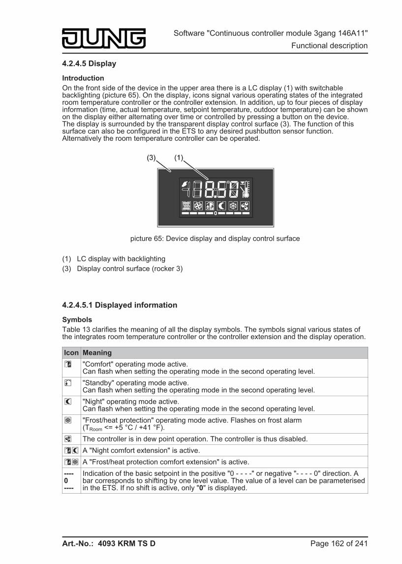
Art.-No.: 4093 KRM TS D
4.2.4.5 Display
Introduction On the front side of the device in the upper area there is a LC display (1) with switchable backlighting (picture 65). On the display, icons signal various operating states of the integrated room temperature controller or the controller extension. In addition, up to four pieces of display information (time, actual temperature, setpoint temperature, outdoor temperature) can be shown on the display either alternating over time or controlled by pressing a button on the device.The display is surrounded by the transparent display control surface (3). The function of this surface can also be configured in the ETS to any desired pushbutton sensor function. Alternatively the room temperature controller can be operated.
picture 65: Device display and display control surface
(1) LC display with backlighting (3) Display control surface (rocker 3)
4.2.4.5.1 Displayed information
Symbols Table 13 clarifies the meaning of all the display symbols. The symbols signal various states of the integrates room temperature controller or the controller extension and the display operation.
Icon Meaning ó "Comfort" operating mode active.
Can flash when setting the operating mode in the second operating level. ô "Standby" operating mode active.
Can flash when setting the operating mode in the second operating level. õ "Night" operating mode active.
Can flash when setting the operating mode in the second operating level. ö "Frost/heat protection" operating mode active. Flashes on frost alarm
(TRoom <= +5 °C / +41 °F). ÷ The controller is in dew point operation. The controller is thus disabled. óõ A "Night comfort extension" is active. óö A "Frost/heat protection comfort extension" is active. ----0----
Indication of the basic setpoint in the positive "0 - - - -" or negative "- - - - 0" direction. A bar corresponds to shifting by one level value. The value of a level can be parameterised in the ETS. If no shift is active, only "0" is displayed.
Page 162 of 241
Software "Continuous controller module 3gang 146A11" Functional description
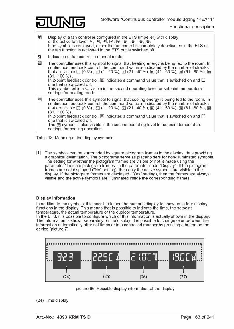
Art.-No.: 4093 KRM TS D
ê Display of a fan controller configured in the ETS (impeller) with displayof the active fan level ë, ì, í, î, ï, ð , ñ , ò, ê.If no symbol is displayed, either the fan control is completely deactivated in the ETS or the fan function is activated in the ETS but is switched off. Ü Indication of fan control in manual mode. â The controller uses this symbol to signal that heating energy is being fed to the room. In
continuous feedback control, the command value is indicated by the number of streaks that are visible Ý (0 %) , Þ (1...20 %), ß (21...40 %), à (41...60 %), á (61...80 %), â (81...100 %) .In 2-point feedback control, â indicates a command value that is switched on and Ý one that is switched off.This symbol â is also visible in the second operating level for setpoint temperature settings for heating mode. è The controller uses this symbol to signal that cooling energy is being fed to the room. In
continuous feedback control, the command value is indicated by the number of streaks that are visible ã (0 %) , ä (1...20 %), å (21...40 %), æ (41...60 %), ç (61...80 %), è (81...100 %) .In 2-point feedback control, è indicates a command value that is switched on and ã one that is switched off.The è symbol is also visible in the second operating level for setpoint temperature settings for cooling operation.
Table 13: Meaning of the display symbols
i The symbols can be surrounded by square pictogram frames in the display, thus providing a graphical delimitation. The pictograms serve as placeholders for non-illuminated symbols.The setting for whether the pictogram frames are visible or not is made using the parameter "Indicate pictogram frames" in the parameter node "Display". If the pictogram frames are not displayed ("No" setting), then only the active symbols are visible in the display. If the pictogram frames are displayed ("Yes" setting), then the frames are always visible and the active symbols are illuminated inside the corresponding frames.
Display information In addition to the symbols, it is possible to use the numeric display to show up to four display functions in the display. This means that is possible to indicate the time, the setpoint temperature, the actual temperature or the outdoor temperature.In the ETS, it is possible to configure which of this information is actually shown in the display.The information is shown separately on the display. It is possible to change over between the information automatically after set times or in a controlled manner by pressing a button on the device (picture 7).
picture 66: Possible display information of the display
(24) Time display
Page 163 of 241
Software "Continuous controller module 3gang 146A11" Functional description
Art.-No.: 4093 KRM TS D
(25) Actual temperature display (room temperature) (26) Setpoint temperature display (27) Outdoor temperature display
Indication of temperature valuesThe indication of the room temperature has a resolution of 0.1 °C and covers a range from -99.9 °C to +99.9 °C. The indication will refresh as soon as the determined room temperature changes within the resolution interval. Should the room temperature reach or go below +5 °C / +41 °F, the symbol ö also flashes in the display as a temperature alarm. The indication of the outdoor temperature has a resolution of 0.1 °C and also covers a range from -99.9 °C to +99.9 °C. The temperature display will refresh as soon as a temperature value telegram is received via the "Outdoor temperature" object. After a device reset, the display shows "---" until a telegram is received. If configured, the outdoor temperature will only be read on the display and cannot be used for any further temperature or variable calculation in the controller.The setpoint temperature is indicated as an absolute temperature value. The currently adjusted setpoint temperature of the active operating mode is displayed. The device always rounds the indication to half degrees and shows the rounded-off temperature in the display. Its possible temperature range depends on the configured operating mode and is given by the fixed values for the frost and/or heat protection temperature. The indication will refresh once a new setpoint temperature for the controller results (e. g. from a change of the operating mode or of the basic setpoint, etc.).The temperatures can be indicated in °C or alternatively in °F. This display format can be configured in common for all temperature values in the "General" parameter node of the ETS.
Indication of time informationThe device possesses an internal clock, set using a communication object. The internal calculation of the current time is primarily influenced by the scope of the internally planned functions and the resulting data traffic. This may cause particularly large time deviations. For this reason, the internal clock should be synchronised on a regular basis. We recommend using, for example, an external KNX/EIB clock with DCF 77 receiver, to set the clock once an hour via the bus and thus keep the deviations as small as possible.After a device reset, the display shows "--:--" until a time signal is received. The same indication will appear unless the internal clock has been updated via the bus at least once a day (updating check at 4:00 a.m.). In both cases, the time is invalid until the first or a new time telegram is received.If the time is invalid, an optional automatic time poll can take place. For this, the "Request time" parameter in the "General" parameter node of the ETS can be set to "Yes". In this case, if the time information is invalid, the device will request time once only by sending a read telegram to the bus. The read request should the be confirmed by an other bus subscriber using an answer telegram.The time can be displayed in the 24h or 12h time format. This property is defined in the ETS in the "General" parameter node. In the 12h time format, the display does not allow any distinction between a.m. and p.m.
Special display informationIn the case of a programming connection to the ETS (programming of the physical address or programming of the application program), "Prog" appears in the display of the device. In the un-programmed delivery state of the device or in the case of an application program loaded via the ETS, the version of the device firmware is shown in the display (e.g. "F1.00") and the operation LED flashes.
Page 164 of 241
Software "Continuous controller module 3gang 146A11" Functional description
Art.-No.: 4093 KRM TS D
4.2.4.5.2 Display control
Backlighting
The display of the device has white backlighting that can be switched or dimmed. The function of the backlighting is specified in the parameter of the same name in the "Display" parameter node in the ETS. The backlighting can be permanently switched on or off. In addition, event-controlled activation of the backlighting is possible by... - pressing any desired control surface and activating the operating mode "Night õ" on the
internal room temperature controller, - pressing any desired control surface and the normal or inverted value of a switching
telegram via the 1-bit communication object "Backlighting On / Off", - pressing any desired control surface and the value of a value telegram via the 1-byte
communication object "Backlighting brightness". The lighting can be dimmed using the value.
If the lighting is switched on by pressing a control surface (rocker or button), the device switches the lighting off automatically when the switch-off time configured in the ETS elapses. The switch-off time is retriggered each time a control surface is actuated. If the lighting is to be switched on in the "Night" operating mode, the lighting remains switched on continuously when night mode is active. Switching on by pressing a button or via the operating mode "Night" always takes place using the brightness value configured in the ETS or specified locally in the second operating level.
When the backlighting is switched by the 1-bit communication object (alternatively to the 1-byte object), the lighting remains switched on continuously according to the switching value (not inverted: "0" = OFF / "1" = ON; inverted: "0" = ON" / "1" = OFF). Here the switch-on brightness is defined by the display brightness value configured in the ETS or specified locally in the second operating level.
In the case of activation by the value object the lighting is dimmed in accordance with the received value ("1...254") or actuated to the maximum ("255"). The value "0" switches the lighting off completely.
Lighting activation by operating a control surface area can be combined with switching or dimming via the corresponding objects. In this case the control via the communication objects has a higher priority. The lighting is switched on automatically by pressing a control surface, and is only switched off again when the switch-off time configured in the ETS elapses, if the lighting is to be switched off via the corresponding communication object (object value "OFF" or "0"). Switching on by pressing a button always takes place using the brightness value configured in the ETS or specified locally in the second operating level.In addition, the lighting can also be switched or dimmed by the communication objects, independently of operation on the device. In this case, the lighting is not switched off automatically when the time has elapsed. The switch-off can then only take place using a switch-off telegram in accordance with the normal or inverted telegram polarity or via a value = "0" It is not possible to switch-off backlighting switched on by operation early using a bus telegram.
Page 165 of 241
Software "Continuous controller module 3gang 146A11" Functional description
Art.-No.: 4093 KRM TS D
i The brightness of the LCD backlighting in the switched-on state (always on, through button-press, night mode or 1-bit object) and the display contrast can be set locally on the device in the second operating level (see chapter 2.5.2. Second operating level). The brightness value set in the second operating level is saved in the device in non-volatile memory, and overwrites the value last programmed using the ETS.When the brightness value is set in the second operating level, the following points must be noted in combination with the 1-byte brightness value object...
- In transition to the second operating level, the lighting is switched on using the value last set via the value object. If the backlighting is controlled exclusively via the value object, the following applies: If the object value is 0...9 %, then the backlighting is controlled to 10% minimum brightness (initial value after commissioning) or to the value last selected in the second control level (10...100%). If the backlighting can also be switched on by pressing a button, the following applies: If the object value is 0...9 %, the backlighting is set to the last value programmed via the ETS or selected in the second operating level (10...100 %).
In the second operating level, the menu item "Brightness" always offers the value from the ETS or the value last set using the buttons "+" or "-". If the menu item "Brightness" is selected, the device always works with the brightness value displayed in the operating level (a before activation of the object value received in the second operating level is then discarded).
- If a brightness value is received while the second operating level is active, then when the second operating level is exited a decision is made whether the settings of the operating level are saved or not. During saving, the brightness value last received by the object is discarded and the value of the operating level is adopted. If no saving is performed, the object value last received is adopted as the new brightness value. In this case the adoption takes place in the configuration "Switching on the lighting by pressing a button and value object" only after the time for automatic switch-off has elapsed.
i After a programming via the ETS or after a bus reset the value of the communication object of the backlighting is always "0", which means that the lighting is switched off.
i Switching on the backlighting or dimming it up is performed immediately. Switching off or dimming down is performed gradually (soft OFF with fixed dimming time implemented).
i In the un-programmed delivery state of the of the device (indication of the firmware version in the display) or during a programming process ("Prog" shown in the display), the brightness value of the backlighting is preset to the initial brightness (70%).
Change-over of the display Up to four pieces of display information (time, actual temperature, setpoint temperature, outdoor temperature) can be shown on the display (see page 163-164). The individual pieces of information are shown separately in the numeric display.
It is possible to switch between the information automatically after set times or, independently of this, in a controlled manner by pressing a button on the device...
- Change-over by time:If more than one piece of display information is configured in the ETS in the parameter node "Display", then the display must be switched over during operation. The ETS parameter "Cyclical change of display functions" specifies the display time of a piece of information. The next piece of information is displayed when this time has elapsed. When the last piece of information has been reached, there is a changeover to the first piece of information.
Page 166 of 241
Software "Continuous controller module 3gang 146A11" Functional description
Art.-No.: 4093 KRM TS D
- Change-over through button-pressIn addition to the cyclical change, the indication can also be switched by pressing a button on the device. To do this it is possible to configure a button for the "Change in the display reading" function. This configuration is performed in the parameter block of the respective button (see chapter 4.2.4.1.12. "Change in the display reading" function). This function can be configured for any desired buttons on the continuous controller module and optionally also for buttons on the expansion module.When a button is pressed, depending on the button parameterisation either the next or the previous display information is called up in accordance with the cyclical change. With this setting the display information specified according to the configuration in the "Display" parameter node can be switched directly.Alternatively it is also possible to call up a particular piece of information immediately independently of the display information of the cyclical change (e.g. push-button function "Call up time"). It is not assumed here that the indication called up in this manner is in fact integrated into the cyclical change. After a piece of information is called up by pressing a button, the indication is retained until the time for the cyclical change has elapsed.
i In the parameter node "Display", it is also possible to set that no information is displayed using the parameter "Number of pieces of display information". In this case the normal depiction of the display is dark (only the symbols of the room temperature controller are displayed). It is then only possible as necessary to call up individual display information by pressing a button using the push-button function "Change in the display reading". The indication called up in this manner then remains temporarily visible in the display depending on the time configured for the cyclical change.
i The piece of display information last called up by the cyclical change or by a button press is overridden and overwritten in the display if the device is operated locally in another way (e.g. temporary setpoint temperature display in the case of setpoint shift, second operating level).
Page 167 of 241
Software "Continuous controller module 3gang 146A11" Functional description
Art.-No.: 4093 KRM TS D
4.2.4.6 Delivery state
Delivery state and non run-capable application For as long as the device has not yet been programmed with application data by means of the ETS, the operation LED flashes at a slow rate (approx. 0.75 Hz). When any of the buttons or rockers is pressed, the appropriate status LED lights up briefly (button-press display). This condition persists until the application is programmed into the device.
By slow flashing of its operation LED (approx. 0.75 Hz), the device can also indicate that a wrong application has been programmed into its memory. Applications are non run-capable if they are not intended for use with the device in the ETS product database. In this case the pushbutton sensor and the integrated room temperature controller are not operational.
Unloading of the application program by the ETS completely deactivates the device function. In this case, the device is not reset to the delivery state described above. The buttons and the status LED do not have a function. Only the operation LED flashes slowly.
In the un-programmed delivery state of the device or in the case of an application program loaded via the ETS, the version of the device firmware is shown in the display (e.g. "F1.00"). The display brightness is set to the initial brightness (70%).
Page 168 of 241
Software "Continuous controller module 3gang 146A11" Functional description
Art.-No.: 4093 KRM TS D
4.2.5 Parameters
4.2.5.1 General parameters
Description Values Comment h General
Transmit delay after reset or bus voltagereturn
Yes
No
After a device reset, the device can automatically transmit telegrams for the "Controller extension" function. The controller extension then attempts to retrieve values from the room temperature controller by means of read telegrams in order to update the object states. If there are still other devices installed in the bus which transmit telegrams immediately after a reset, it may be useful here to activate the transmit delay for automatically transmitting objects of the controller extension and the room temperature measurement in order to reduce the bus load.
When transmit delay is activated (setting: "Yes"), the device computes the delay time from its device ID in the physical address. There is a maximum delay of 30 seconds before the telegrams are transmitted.
Light period of status LED for button-press display
1 s2 s3 s4 s5 s
This parameter defines the switch-on time the status LED is lit up to indicate actuation. The setting concerns all status LEDs whose function is set to "Button-press display".
Function of operation LED
This parameter defines the function of the operation LED.
Always OFF The operation LED is always off.
Always ON The operation LED is always on, for instance, as orientation lighting.
Control via object The operation LED is controlled by a separate communication object.
Flashing The operation LED flashes permanently with a frequency of about 0.75 Hz.
Besides the function set here, the operation LED can display different states by means of other flashing rates. These comprise Programming mode, the confirmation of full-surface actuation or the message that an application has not been loaded.
Page 169 of 241
Software "Continuous controller module 3gang 146A11" Parameters
Art.-No.: 4093 KRM TS D
Control of the operation LED via the object value
1 = LED static ON /0 = LED static OFF
1 = LED static OFF /0 = LED static ON
1 = LED flashes /0 = LED static OFF
1 = LED static OFF /0 = LED flashes
If the "Function of the operation LED" is set to "Control via object", then the telegram polarity of the 1-bit object "T.Operation LED" can be specified at this point.The LED can be switched on or off statically. In addition, the received switching telegram can be evaluated in such a way that the LED flashes.
Temperature display °C°F
The temperatures can be indicated in the display of the device in °C or alternatively in °F. This display format can be configured in the ETS in common for all temperature values using this parameter.
Time display 24 hours12 hours
The time can be displayed in the 24h or 12h time format. In the 12h time format, the display does not allow any distinction between a.m. and p.m.
Request time NoYes
The device possesses an internal clock, set using a communication object. The internal calculation of the current time is primarily influenced by the scope of the internally planned functions and the resulting data traffic. This may cause particularly large time deviations. For this reason, the internal clock should be synchronised on a regular basis.The device will consider the internal time invalid for as long as no time telegram is received after a device reset, or if there has been no update for a day. In this case, an optional automatic time poll can take place. For this, the automatic time poll can be activated using the "Yes" setting here. In so doing, if the time information is invalid, the device will request the time once only by sending a read telegram to the bus. The read request should the be confirmed by an other bus subscriber using an answer telegram.
Request time with 1 telegram
0 telegram
In order to request the time, the telegram polarity of the request telegram can be configured here.
Second operating level DisabledEnabled
The second operating level makes it possible to make various basic settings on the unit locally without using the ETS. In order to avoid the unintentional disruption of essential functions, access to the entire second operating level can
Page 170 of 241
Software "Continuous controller module 3gang 146A11" Parameters
Art.-No.: 4093 KRM TS D
be prevented by setting this parameter to "disabled". The setting "enabled" allows access to the second display operating level. Additional parameters then become visible in the ETS.
h Second operating level (Only visible if parameter "Second operating level" under "General" is set to "enabled"!)
Change continuous controller in second operating level
Hidden
Visible
This parameter specifies whether the settings of the continuous controller are displayed in the second display operating level ("Visible" setting). The settings of the continuous controller are the basic setpoint and the setpoint temperatures for Standby and Night mode for heating and cooling. Whether these temperature values are not just displayed, but can also be changed, is specified by additional parameters in the parameter node "Room temperature control -> Controller general -> Second operating level".With the setting "Hidden" the setpoint temperatures of continuous controller are not shown in the second operating level, and thus cannot be changed, either.This parameter has no effect in a controller extension.
Change presence in second operating level
Hidden
Visible
This parameter specifies whether the presence mode of the continuous controller can be set in the second display operating level ("Visible" setting).With the setting "Hidden", it is not possible to set the presence mode in the second operating level.This parameter has no effect in a controller extension.
Change setpoint shift in second operating level
Hidden
Visible
This parameter specifies whether the setpoint shift of the continuous controller can be set in the second display operating level ("Visible" setting).With the setting "Hidden", it is not possible to set the setpoint shift in the second operating level.This parameter has no effect in a controller extension.
Change operating mode in second operating level
Hidden
Visible
This parameter specifies whether the operating mode of the continuous controller can be set in the second display operating level ("Visible" setting).With the setting "Hidden", it is not possible to set the operating mode in the second operating level.
Page 171 of 241
Software "Continuous controller module 3gang 146A11" Parameters
Art.-No.: 4093 KRM TS D
This parameter has no effect in a controller extension.
Change fan levels in second operating level
Hidden
Visible
This parameter specifies whether fan control is possible in the second display operating level ("Visible" setting). The menu item "Fans" is actually only visible in the operating level if the fan control has been configured as present under "Room temperature control -> Controller general".With the setting "Hidden", fan control is not possible in the second operating level.This parameter has no effect in a controller extension.
Displaying the time in the second operating level
Hidden
Visible
The current time can optionally be displayed in the second operating level ("Visible" setting). With the setting "Hidden", the time is not displayed in the second operating level. This can then be configured only if needed in the basic display ("Display" parameter node).
Displaying the actual temperature in the second operating level
Hidden
Visible
The actual temperature (room temperature) can optionally be displayed in the second operating level ("Visible" setting). With the setting "Hidden", the actual temperature is not displayed in the second operating level. This can then be configured only if needed in the basic display ("Display" parameter node).
Displaying the setpoint temperature in the second operating level
Hidden
Visible
The setpoint temperature (room temperature) can optionally be displayed in the second operating level ("Visible" setting). With the setting "Hidden", the setpoint temperature is not displayed in the second operating level. This can then be configured only if needed in the basic display ("Display" parameter node).
Displaying the outdoor temperature in the second operating level
Hidden
Visible
The outdoor temperature can optionally be displayed in the second operating level ("Visible" setting). With the setting "Hidden", the outdoor temperature is not displayed in the second operating level. This can then be configured only if needed in the basic display ("Display" parameter node).
Page 172 of 241
Software "Continuous controller module 3gang 146A11" Parameters
Art.-No.: 4093 KRM TS D
First menu item in the second operating level
Continuous controllerPresenceSetpoint shiftOperating modeFan levelsTimeActual temperatureSetpoint temperatureOutdoor temperature
The menu entry that is shown as the first entry when the second operating level is called up can be selected using this parameter. The sequence of the subsequent entries is fixed as shown in the parameter structure.
Automatic exiting of the second operating level?
YesNo
This parameter can be used to configure the automatic exiting of the second operating level. In the "Yes" setting the device leaves the second operating level when no additional operation takes place after the last push-button operation within the "Time until automatic exit" configured in the ETS. With "No" the second operating level remains active until it is exited manually with the button combination or using the menu entries "OK" or "ESC".
Time until automatic exit 10 s20 s30 s1 min.2 mins.
This parameter specifies the time until automatic exiting of the second operating level after no more buttons are pressed. This parameter is only visible if the parameter "Automatic exiting of the second operating level?" is set to "Yes".
Save changes after automatic exiting?
YesNo
For automatic exiting of the second operating level, this parameter can be used to define whether the settings are saved or not.
Save changes after exiting with button combination?
YesNo
This parameter defines whether the settings are saved or not when the second operating level is exited using the button combination.
Page 173 of 241
Software "Continuous controller module 3gang 146A11" Parameters
Art.-No.: 4093 KRM TS D
4.2.5.2 Parameter for room temperature measurement
Description Values Comment h Room temperature measurement
Temperature detection Internal sensorExternal sensorInternal and external sensor
This parameter specifies which sensor is used for room temperature measurement.With the setting "Internal sensor" only the temperature sensor integrated in the device detects the room temperature.With the setting "External sensor" only a KNX/EIB temperature sensor (e.g. controller extension) coupled via the "External temperature sensor" object detects the room temperature.With the setting "Internal and external sensor" the sensor integrated in the device and a KNX/EIB temperature sensor (e.g. controller extension) coupled via the "External temperature sensor" object detect the room temperature.
Determination of measured value from internal / external ratio
10% to 90%20% to 80%30% to 70%40% to 60%50% to 50%60% to 40%70% to 30%80% to 20%90% to 10%
The weighting of the measured temperature value for the internal and external sensors is specified here. That results in an overall value, which will be used for the further evaluation of the room temperature.
Internal sensor calibration(-128...127) * 0.1 K
-128...10...127 Determines the value by which the internal sensor’s room temperature value is calibrated.This parameter is only visible when the temperature recording system requires an internal sensor.
External sensor calibration(-128...127) * 0.1 K
-128...0...127 Determines the value by which the external sensor’s room temperature value is calibrated.This parameter is only visible when the temperature recording system requires an external sensor.
Polling time for external sensors(0...255) * 1 min; 0 = inactive
0 ... 255 The polling time for the external sensor’s temperature value is specified here. In the "0" setting, the external sensor is not automatically polled by the controller. In this case, the sensor must transmit its temperature value itself.
Page 174 of 241
Software "Continuous controller module 3gang 146A11" Parameters
Art.-No.: 4093 KRM TS D
Transmission when room temperature change by(0..255) * 0.1 K; 0 = No automatic transmission
0 ... 255, 3 Determines the size of the value change of the room temperature after which the current values are automatically transmitted on the bus via the "Actual temperature" object.
Cyclical transmission of room temperature(0...255) * 1 min; 0 = inactive
0 ... 255, 15 This parameter specifies whether and when the determined room temperature of the first control circuit is to be periodically output via the "Actual temperature" object.
Page 175 of 241
Software "Continuous controller module 3gang 146A11" Parameters
Art.-No.: 4093 KRM TS D
4.2.5.3 Parameters on the pushbutton sensor function section
Description Values Comment hPushbutton -> Button configuration
Continuous controller module...
Only indication of the button pairs present on the continuous controller module.
Pushbutton sensor expansion module...
Not presentPresent
If an expansion module is connected to the continuous controller module, then the module button pairs present on the expansion module must be enabled using this parameter.Module buttons may only be enabled if an expansion module is actually connected to the continuous controller module!
hPushbutton sensor -> Button configuration -> Operation concept of continuous controller module
Operation concept of buttons 1 and 2
(The same parameters are available for the other control surfaces / button pairs of the continuous controller module.)
Rocker function (rocker 1)
Push-button function
For each control surface, the user can specify independently whether it is to be used as a rocker with a common basic function or as two different buttons with completely independent functions.Depending on this setting, the ETS displays different communication objects and parameter pages.
Button evaluation
(The same parameters are available for the other control surfaces / button pairs of the continuous controller module.)
Single area operation (only as button 1)Double-area operation (as buttons 1 + 2)
If the operation concept of a control surface is configured as "push-button function", this parameter can be used to specify whether single-surface or double-surface operation should be implemented.In single-surface operation, the entire control surface is evaluated only as a single "large" button. The surface can be depressed at any desired point in order to execute the underlying push-button function. In this setting, the button with the even button number of the button pair (e.g. button 2) is inactive and physically not present.In double-surface operation, the control surface is divided into two mutually independent buttons.
Button arrangement
(The same parameters are available for the other control surfaces / button pairs of the
Left / right
Top / bottom
In the rocker function and in the push-button function with double-surface principle, for each control surface the user can independently specify whether it is to be divided horizontally or vertically. This defines the actuation points of the control surface.
Page 176 of 241
Software "Continuous controller module 3gang 146A11" Parameters
Art.-No.: 4093 KRM TS D
continuous controller module.)
The button arrangement is preset to "left / right" only for the display control surface (buttons 5 & 6).
hPushbutton sensor -> Button configuration -> Operation concept of expansion module
Operation concept of buttons 7 and 8
(For the other control surfaces / button pairs of the expansion module, the same parameters are available.)
Rocker function(Rocker 4)
Push-button function
For each control surface of the expansion module, the user can specify independently whether it is to be used as a rocker with a common basic function or as two different buttons with completely independent functions.Depending on this setting, the ETS displays different communication objects and parameter pages.
Button evaluation
(For the other control surfaces / button pairs of the expansion module, the same parameters are available.)
Single area operation (only as button 7)Double-area operation (as buttons 7 + 8)
If the operation concept of a control surface is configured as "push-button function", this parameter can be used to specify whether single-surface or double-surface operation should be implemented.In single-surface operation, the entire control surface is evaluated only as a single "large" button. The surface can be depressed at any desired point in order to execute the underlying push-button function. In this setting, the button with the even button number of the button pair (e.g. button 10) is inactive and physically not present.In double-surface operation, the control surface is divided into two mutually independent buttons.
Button arrangement
(For the other control surfaces / button pairs of the expansion module, the same parameters are available.)
Left / right
Top / bottom
In the rocker function and in the push-button function with double-surface principle, for each control surface the user can independently specify whether it is to be divided horizontally or vertically. This defines the actuation points of the control surface.
h Pushbutton sensor -> Button configuration -> Operation concept... -> Rocker 1 (Buttons 1/2)(Only if "Function of buttons 1 and 2 = as one rocker (rocker 1)"!)
Function SwitchingDimmingVenetian blind1-byte value transmitter2-byte value transmitterScene extension2-channel operation
This parameter is used to define the basic function of the rocker.Depending on this choice, the ETS displays different communication objects and parameters for this rocker.
Page 177 of 241
Software "Continuous controller module 3gang 146A11" Parameters
Art.-No.: 4093 KRM TS D
The following parameters are only valid for the rocker function "Switching"...
Command on pressing rocker 1.1
No reactionONOFFTOGGLE
Depending on the "button arrangement" parameter, these parameters define the reaction that takes place when the top (or left-hand) rocker is pressed or released.
Command on releasing rocker 1.1
No reactionONOFFTOGGLE
Command on pressing rocker 1.2
No reactionONOFFTOGGLE
Depending on the "button arrangement" parameter, these parameters define the reaction that takes place when the bottom (or right-hand) rocker is pressed or released.
Command on releasing rocker 1.2
No reactionONOFFTOGGLE
The following parameters are only valid for the rocker function "Dimming"...
Command on pressing rocker 1.1
No reactionBrighter (ON)Darker (OFF)Brighter / darker (TOGGLE)Brighter (TOGGLE)Darker (TOGGLE)
Depending on the "Button arrangement" parameter, this parameter defines the reaction that takes place when the top (or left-hand) rocker is pressed.If the pushbutton sensor is to toggle on a brief press, the corresponding switching objects of other sensors with the same function must be linked with one another. In the "Brighter/darker (TOGGLE)" setting, the dimming objects must be interlinked as well so that the pushbutton sensor can send the correct telegram on the next button-press.
Command on pressing rocker 1.2
No reactionBrighter (ON)Darker (OFF)Brighter / darker (TOGGLE)Brighter (TOGGLE)Darker (TOGGLE)
Depending on the "Button arrangement" parameter, this parameter defines the reaction that takes place when the bottom (or right-hand) rocker is pressed.If the pushbutton sensor is to toggle on a brief press, the corresponding switching objects of other sensors with the same function must be linked with one another. In the "Brighter/darker (TOGGLE)" setting, the dimming objects must be interlinked as well so that the pushbutton sensor can send the correct telegram on the next button-press.
Time between switching and dimming, rocker 1.1(100 … 50000 x 1 ms)
100 … 400 … 50000 This parameter defines how long the top (or left-hand) rocker must be pressed for the pushbutton sensor to send a
Page 178 of 241
Software "Continuous controller module 3gang 146A11" Parameters
Art.-No.: 4093 KRM TS D
dimming telegram.
Time between switching and dimming, rocker 1.2(100 … 50000 x 1 ms)
100 … 400 … 50000 This parameter defines how long the bottom (or right-hand) rocker must be pressed for the pushbutton sensor to send a dimming telegram.
Advanced parameters ActivatedDeactivated
When the advanced parameters are activated, the ETS shows the following parameters.
Advanced parameters activated...
Increase brightness by 1.5 %3 %6 %12.5 %25 %50 %100 %
This parameter sets the relative dimming level when the brightness is increased. On each button-press, the brightness is changed at maximum by the configured level.Especially with smaller dimming levels it is advisable for the pushbutton sensor to repeat the dimming telegrams automatically (see "telegram repetition").
Reduce brightness by 1.5 %3 %6 %12.5 %25 %50 %100 %
This parameter sets the relative dimming level when the brightness is reduced. On each button-press, the brightness is changed at maximum by the configured level.Especially with smaller dimming levels it is advisable for the pushbutton sensor to repeat the dimming telegrams automatically (see "telegram repetition").
Transmit stop telegram? Yesno
On "Yes" the pushbutton sensor transmits a telegram for stopping the dimming process when the rocker is released. When the pushbutton sensor transmits telegrams for dimming in smaller levels, the stop telegram is generally not needed.
Telegramrepeat?
YesNo
This parameter can be used to activate telegram repetition for dimming. With the button held down, the pushbutton sensor will then transmit the relative dimming telegrams (in the programmed level width) until the button is released.
Time between two telegrams
200 ms300 ms400 ms500 ms
This parameter defines the interval at which the dimming telegrams are automatically repeated in the telegram repetition mode. Only visible if
Page 179 of 241
Software "Continuous controller module 3gang 146A11" Parameters
Art.-No.: 4093 KRM TS D
750 ms1 s2 s
"Telegram repetition = Yes"!
Full-surface operation Enabled
Disabled
When the full-surface operation is enabled, the ETS shows the following parameters.
Function for full-surface operation
Switching
Scene recall without storage function
Scene recall with storage function
In case of full-surface operation, this parameter defines the function that is to be used. The ETS shows the corresponding communication object and the other parameters.If the pushbutton sensor is to recall a scene with storage function by full-surface actuation, it will make a distinction between a brief press (less than 1 s), a sustained press (longer than 5 s) and an invalid button-press (between 1 s and 5 s). A brief press recalls the scene, a sustained press stores a scene and an invalid full-surface operation is ignored.Only visible if "Full-surface operation = enabled"!
Command for full-surface operation
ONOFFTOGGLE
This parameter defines the value of the transmitted telegram when a full-surface operation has been sensed. "TOGGLE" changes over the current object value.Only visible if "Full-surface operation = enabled"!
Scene number (1 … 64) 1, 2, …, 64 This parameter defines the scene number which is to be transmitted to the bus after a scene recall or during storage of a scene.Only visible if "Full-surface operation = enabled"!
The following parameters are only valid for the rocker function "Venetian blind"...
Command on pressing rocker
Rocker X.1:UP /Rocker X.2: DOWN
Rocker X.1:DOWN /Rocker X.2: UP
Rocker X.1:TOGGLE /Rocker X.2:TOGGLE
This parameter defines the running direction of a drive after a button-press. If the setting is "TOGGLE", the direction is changed after each long time command. If several pushbuttons are to control the same drive, the long time objects of the pushbuttons must be interlinked for a correct change of the running direction.
Operation concept short – long – short For Venetian blind control, four different operation concepts can be selected. For
Page 180 of 241
Software "Continuous controller module 3gang 146A11" Parameters
Art.-No.: 4093 KRM TS D
long – short
short – long
Long – short or short
these concepts, the ETS shows further parameters.
Time between short-time and long-time commandRocker 1.1(1 … 3000 x 100 ms)
1 … 4 … 3000 This parameter sets the time after which the long-time operation will be evaluated on pressing the top (or left-hand) button of the rocker. This parameter is not visible with "Operation concept = long – short"!
Time between short-time and long-time commandRocker 1.2(1 … 3000 x 100 ms)
1 … 4 … 3000 This parameter sets the time after which the long-time operation will be evaluated on pressing the bottom (or right-hand) button of the rocker. This parameter is not visible with "Operation concept = long – short"!
Slat adjusting time rocker 1.1(0 … 3000 x 100 ms)
0 … 5 … 3000 Time during which a transmitted long time telegram can be terminated by releasing the top (or left-hand) button of the rocker (short time). This function serves to adjust the slats of a blind. This parameter is not visible with "Operation concept = long – short"!
Slat adjusting time, rocker 1.2(0 … 3000 x 100 ms)
0 … 5 … 3000 Time during which a transmitted long time telegram can be terminated by releasing the bottom (or right-hand) button of the rocker (short time). This function serves to adjust the slats of a blind. This parameter is not visible with "Operation concept = long – short"!
Full-surface operation Enabled
Disabled
When the full-surface operation is enabled, the ETS shows the following parameters. Full-surface operation can only be programmed if "Operation concept = long – short or short"!
Function for full-surface operation
Switching
Scene recall without storage function
Scene recall with storage function
In case of full-surface operation, this parameter defines the function that is to be used. The ETS shows the corresponding communication object and the other parameters.If the pushbutton sensor is to recall a scene with storage function by full-surface actuation, it will make a distinction between a brief press (less than 1 s), a sustained press (longer than 5 s) and an invalid button-press (between 1 s and 5 s). A brief press
Page 181 of 241
Software "Continuous controller module 3gang 146A11" Parameters
Art.-No.: 4093 KRM TS D
recalls the scene, a sustained press stores a scene and an invalid full-surface operation is ignored.Only visible if "Full-surface operation = enabled"!
Command for full-surface operation
ONOFFTOGGLE
This parameter defines the value of the transmitted telegram when a full-surface operation has been sensed. "TOGGLE" changes over the current object value.Only visible if "Full-surface operation = enabled"!
Scene number (1 … 64) 1, 2, …, 64 This parameter defines the scene number which is to be transmitted to the bus after a scene recall or during storage of a scene.Only visible if "Full-surface operation = enabled"!
The following parameters are only valid for the rocker function "Value transmitter 1-byte"...
Function Rocker X.1 /X.2 no function
Rocker X.1: 0 … 255 /Rocker X.2: 0 … 255
Rocker X.1: 0 … 100 % /Rocker X.2: 0 … 100 %
Rocker X.1: 0 … 255 /Rocker X.2: no function
Rocker X.1: 0 … 100 % /Rocker X.2: no function
Rocker X.1: no function /Rocker X.2: 0 … 255
Rocker X.1: no function /Rocker X.2: 0 … 100 %
A rocker configured as "Value transmitter 1 byte" permits selecting whether the values to be transmitted are interpreted as integers from 0 to 255 or as a percentage from 0 % to 100 %. The following parameters and their settings depend on this distinction.
Value, rocker 1.1(0 … 255)
0...255 Depending on the "Button arrangement" parameter, this parameter defines the object value when the top (or left-hand) rocker is pressed. Only visible if "Function = … 0…255"!
Value, rocker 1.2(0 … 255)
0...255 Depending on the "Button arrangement" parameter, this parameter defines the object value when the bottom (or right-hand) rocker is pressed. Only visible if "Function = … 0…255"!
Page 182 of 241
Software "Continuous controller module 3gang 146A11" Parameters
Art.-No.: 4093 KRM TS D
Value, rocker 1.1(0 … 100 %)
0...100 Depending on the "Button arrangement" parameter, this parameter defines the object value when the top (or left-hand) rocker is pressed. Only visible if "Function = … 0…100 %"!
Value, rocker 1.2(0 … 100 %)
0...100 Depending on the "Button arrangement" parameter, this parameter defines the object value when the bottom (or right-hand) rocker is pressed. Only visible if "Function = … 0…100 %"!
Value adjustment by long button-press
Enabled
Disabled
If value adjustment by long button-press is enabled, the ETS shows further parameters.Value adjustment begins, when the button is held down for more than 5 s. In this case, the respective status LED flashes as a sign that a new telegram has been transmitted.
Starting value in case of value adjustment
Same as configured value
Same as value after last adjustment
Same as value from communication object
Value adjustment can begin with different starting values. In the setting "Same as parameterised value", after each long press the pushbutton sensor always starts with the value programmed in the ETS. In the setting "Same as value after last adjustment", after a long press the pushbutton sensor starts with the value transmitted by itself or by another device with this group address as the last value.In the setting "Same as value from communication object", after a long press the pushbutton sensor starts with the value transmitted by itself or by another device with this group address as the last value.This parameter is only visible if "Value adjustment by long button-press = enabled"!
Direction of value adjustment
Upwards
Downwards
Toggling (alternating)
With a long press, the pushbutton sensor can either vary the values always in the same direction or it stores the direction of the last adjustment and reverses it on the next button-press.This parameter is only visible if "Value adjustment by long button-press = enabled"!
Level size (1 … 15) 1...15 In a value adjustment, the pushbutton sensor determines the new telegram value from the previous value and the preset level size. If the value falls below
Page 183 of 241
Software "Continuous controller module 3gang 146A11" Parameters
Art.-No.: 4093 KRM TS D
the lower limit of the adjustment range (0 or 0 %) or if it exceeds the upper limit (255 or 100%), the sensor adapts the level size of the last level automatically.This parameter is only visible if "Value adjustment by long button-press = enabled"!
Time between two telegrams
0.5 s1 s2 s3 s
In a value adjustment, the pushbutton sensor determines the new telegram value from the previous value and the preset level size. If the value falls below the lower limit of the adjustment range (0 or 0 %) or if it exceeds the upper limit (255 or 100%), the sensor adapts the level size of the last level automatically.This parameter is only visible if "Value adjustment by long button-press = enabled"!
Value adjustment with overflow
Yes
No
If value adjustment is to be effected without overflow (setting "No") and if the pushbutton sensor reaches the lower limit of the adjustment range (0 or 0 %) or the upper limit (255 or 100 %) during value adjustment, the adjustment will be stopped automatically by the sensor.If the value adjustment with overflow is programmed (setting "Yes") and if the pushbutton sensor reaches the lower or the upper limit, it will transmit the value of this range limit and then add a pause the duration of which corresponds to two levels. Thereafter, the pushbutton sensor transmits a telegram with the value of the other range limit and continues the value adjustment in the same direction.
The following parameters are only valid for the rocker function "Value transmitter 2-byte"...
Function Temperature value transmitter
Brightness value transmitter
Value transmitter (0 … 65535)
A rocker configured as "Value transmitter 1 byte" permits selecting whether the values to be transmitted are to be interpreted as temperature values (0 °C to 40 °C), as brightness values (0 lux to 1500 lux) or as integers (0 to 65535). The following parameters and their settings depend on this selection.
Temperature value (0 … 40 °C)Rocker 1.1
0...20...40 Depending on the "Button arrangement" parameter, this parameter defines the object value when the top (or left-hand) rocker is pressed. Only visible if "Function = Temperature value transmitter"!
Page 184 of 241
Software "Continuous controller module 3gang 146A11" Parameters
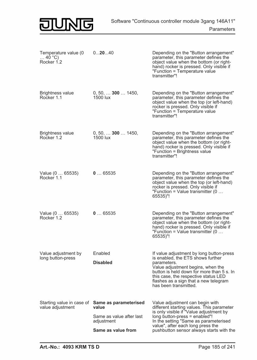
Art.-No.: 4093 KRM TS D
Temperature value (0 … 40 °C)Rocker 1.2
0...20...40 Depending on the "Button arrangement" parameter, this parameter defines the object value when the bottom (or right-hand) rocker is pressed. Only visible if "Function = Temperature value transmitter"!
Brightness valueRocker 1.1
0, 50, … 300 … 1450,1500 lux
Depending on the "Button arrangement" parameter, this parameter defines the object value when the top (or left-hand) rocker is pressed. Only visible if "Function = Temperature value transmitter"!
Brightness valueRocker 1.2
0, 50, … 300 … 1450,1500 lux
Depending on the "Button arrangement" parameter, this parameter defines the object value when the bottom (or right-hand) rocker is pressed. Only visible if "Function = Brightness value transmitter"!
Value (0 … 65535)Rocker 1.1
0 … 65535 Depending on the "Button arrangement" parameter, this parameter defines the object value when the top (or left-hand) rocker is pressed. Only visible if "Function = Value transmitter (0 … 65535)"!
Value (0 … 65535)Rocker 1.2
0 … 65535 Depending on the "Button arrangement" parameter, this parameter defines the object value when the bottom (or right-hand) rocker is pressed. Only visible if "Function = Value transmitter (0 … 65535)"!
Value adjustment by long button-press
Enabled
Disabled
If value adjustment by long button-press is enabled, the ETS shows further parameters.Value adjustment begins, when the button is held down for more than 5 s. In this case, the respective status LED flashes as a sign that a new telegram has been transmitted.
Starting value in case of value adjustment
Same as parameterised value
Same as value after last adjustment
Same as value from
Value adjustment can begin with different starting values. This parameter is only visible if "Value adjustment by long button-press = enabled"!In the setting "Same as parameterised value", after each long press the pushbutton sensor always starts with the
Page 185 of 241
Software "Continuous controller module 3gang 146A11" Parameters
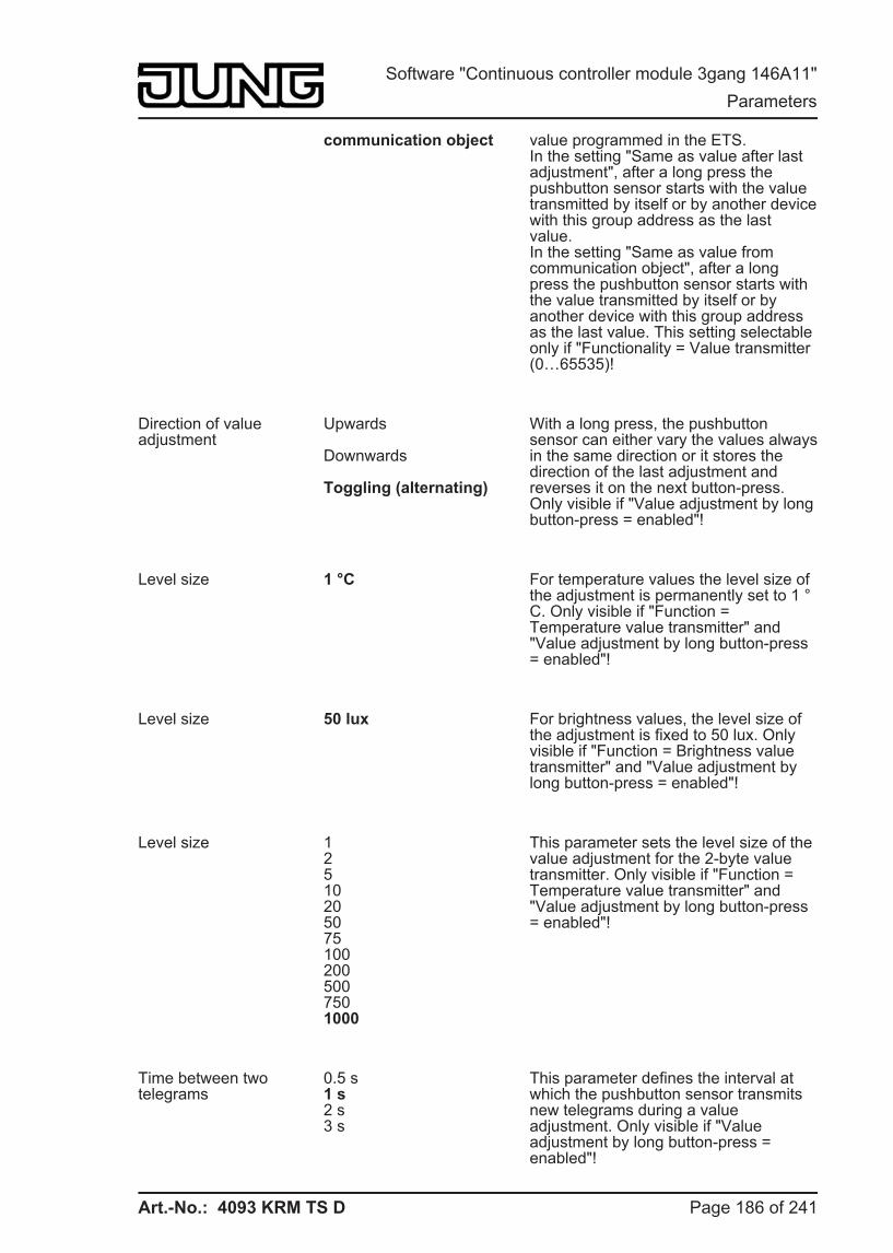
Art.-No.: 4093 KRM TS D
communication object value programmed in the ETS.In the setting "Same as value after last adjustment", after a long press the pushbutton sensor starts with the value transmitted by itself or by another device with this group address as the last value.In the setting "Same as value from communication object", after a long press the pushbutton sensor starts with the value transmitted by itself or by another device with this group address as the last value. This setting selectable only if "Functionality = Value transmitter (0…65535)!
Direction of value adjustment
Upwards
Downwards
Toggling (alternating)
With a long press, the pushbutton sensor can either vary the values always in the same direction or it stores the direction of the last adjustment and reverses it on the next button-press. Only visible if "Value adjustment by long button-press = enabled"!
Level size 1 °C For temperature values the level size of the adjustment is permanently set to 1 °C. Only visible if "Function = Temperature value transmitter" and "Value adjustment by long button-press = enabled"!
Level size 50 lux For brightness values, the level size of the adjustment is fixed to 50 lux. Only visible if "Function = Brightness value transmitter" and "Value adjustment by long button-press = enabled"!
Level size 125102050751002005007501000
This parameter sets the level size of the value adjustment for the 2-byte value transmitter. Only visible if "Function = Temperature value transmitter" and "Value adjustment by long button-press = enabled"!
Time between two telegrams
0.5 s1 s2 s3 s
This parameter defines the interval at which the pushbutton sensor transmits new telegrams during a value adjustment. Only visible if "Value adjustment by long button-press = enabled"!
Page 186 of 241
Software "Continuous controller module 3gang 146A11" Parameters
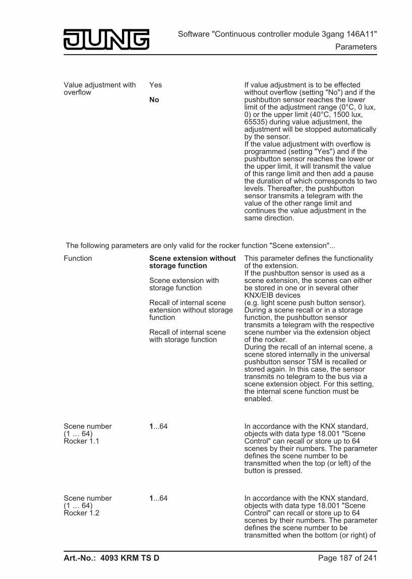
Art.-No.: 4093 KRM TS D
Value adjustment with overflow
Yes
No
If value adjustment is to be effected without overflow (setting "No") and if the pushbutton sensor reaches the lower limit of the adjustment range (0°C, 0 lux, 0) or the upper limit (40°C, 1500 lux, 65535) during value adjustment, the adjustment will be stopped automatically by the sensor.If the value adjustment with overflow is programmed (setting "Yes") and if the pushbutton sensor reaches the lower or the upper limit, it will transmit the value of this range limit and then add a pause the duration of which corresponds to two levels. Thereafter, the pushbutton sensor transmits a telegram with the value of the other range limit and continues the value adjustment in the same direction.
The following parameters are only valid for the rocker function "Scene extension"...
Function Scene extension without storage function
Scene extension with storage function
Recall of internal scene extension without storage function
Recall of internal scene with storage function
This parameter defines the functionality of the extension.If the pushbutton sensor is used as a scene extension, the scenes can either be stored in one or in several other KNX/EIB devices (e.g. light scene push button sensor). During a scene recall or in a storage function, the pushbutton sensor transmits a telegram with the respective scene number via the extension object of the rocker.During the recall of an internal scene, a scene stored internally in the universal pushbutton sensor TSM is recalled or stored again. In this case, the sensor transmits no telegram to the bus via a scene extension object. For this setting, the internal scene function must be enabled.
Scene number(1 … 64)Rocker 1.1
1...64 In accordance with the KNX standard, objects with data type 18.001 "Scene Control" can recall or store up to 64 scenes by their numbers. The parameter defines the scene number to be transmitted when the top (or left) of the button is pressed.
Scene number(1 … 64)Rocker 1.2
1...64 In accordance with the KNX standard, objects with data type 18.001 "Scene Control" can recall or store up to 64 scenes by their numbers. The parameter defines the scene number to be transmitted when the bottom (or right) of
Page 187 of 241
Software "Continuous controller module 3gang 146A11" Parameters
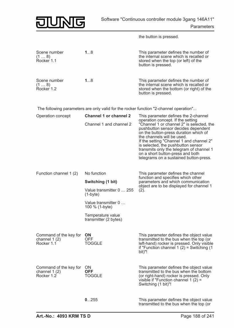
Art.-No.: 4093 KRM TS D
the button is pressed.
Scene number(1 … 8)Rocker 1.1
1...8 This parameter defines the number of the internal scene which is recalled or stored when the top (or left) of the button is pressed.
Scene number(1 … 8)Rocker 1.2
1...8 This parameter defines the number of the internal scene which is recalled or stored when the bottom (or right) of the button is pressed.
The following parameters are only valid for the rocker function "2-channel operation"...
Operation concept Channel 1 or channel 2
Channel 1 and channel 2
This parameter defines the 2-channel operation concept. If the setting "Channel 1 or channel 2" is selected, the pushbutton sensor decides dependent on the button-press duration which of the channels will be used.If the setting "Channel 1 and channel 2" is selected, the pushbutton sensor transmits only the telegram of channel 1 on a short button-press and both telegrams on a sustained button-press.
Function channel 1 (2) No function
Switching (1 bit)
Value transmitter 0 … 255 (1-byte)
Value transmitter 0 … 100 % (1-byte)
Temperature value transmitter (2 bytes)
This parameter defines the channel function and specifies which other parameters and which communication object are to be displayed for channel 1 (2).
Command of the key for channel 1 (2)Rocker 1.1
ONOFFTOGGLE
This parameter defines the object value transmitted to the bus when the top (or left-hand) rocker is pressed. Only visible if "Function channel 1 (2) = Switching (1 bit)"!
Command of the key for channel 1 (2)Rocker 1.2
ONOFFTOGGLE
This parameter defines the object value transmitted to the bus when the bottom (or right-hand) rocker is pressed. Only visible if "Function channel 1 (2) = Switching (1 bit)"!
0...255 This parameter defines the object value transmitted to the bus when the top (or
Page 188 of 241
Software "Continuous controller module 3gang 146A11" Parameters
Art.-No.: 4093 KRM TS D
Value of the button forChannel 1 (2)Rocker 1.1 (0...255)
left-hand) rocker is pressed. Only visible if "Function channel 1 (2) = value transmitter 0…255 (1 byte)"!
Value of the button forChannel 1 (2)Rocker 1.2 (0...255)
0...255 This parameter defines the object value transmitted to the bus when the bottom (or right-hand) rocker is pressed. Only visible if "Function channel 1 (2) = value transmitter 0…255 (1 byte)"!
Value of the button forChannel 1 (2)Rocker 1.1 (0 … 100 %)
0...100 This parameter defines the object value transmitted to the bus when the top (or left-hand) rocker is pressed. Only visible if "Function channel 1 (2) = value transmitter 0…100 % (1 byte)"!
Value of the button forChannel 1 (2)Rocker 1.2 (0 … 100 %)
0...100 This parameter defines the object value transmitted to the bus when the bottom (or right-hand) rocker is pressed. Only visible if "Function channel 1 (2) = value transmitter 0…100 % (1 byte)"!
Temperature value of the key for channel 1 (2)Rocker 1.1 (0 … 40 °C)
0...40 This parameter defines the temperature value transmitted to the bus when the top (or left-hand) rocker is pressed. Only visible if "Function channel 1 (2) = Temperature value transmitter (2 bytes)"!
Temperature value of the key for channel 1 (2)Rocker 1.2 (0 … 40 °C)
0...40 This parameter defines the temperature value transmitted to the bus when the bottom (or right-hand) rocker is pressed. Only visible if "Function channel 1 (2) = Temperature value transmitter (2 bytes)"!
Time between channel 1 and channel 2Rocker 1.1(1 … 255 x 100 ms)
0...30...255 Depending on the selected operation concept, this parameter defines the interval at which the push-button transmits the telegram for channel 1 and the telegram for channel 2 when the top (or left side) of the rocker is pressed.
Time between channel 1 and channel 2Rocker 1.2(1 … 255 x 100 ms)
0...30...255 Depending on the selected operation concept, this parameter defines the interval at which the push-button transmits the telegram for channel 1 and the telegram for channel 2 when the bottom (or right side) of the rocker is pressed.
Page 189 of 241
Software "Continuous controller module 3gang 146A11" Parameters
Art.-No.: 4093 KRM TS D
Full-surface operation Enabled
Disabled
When the full-surface operation is enabled, the ETS shows the following parameters. Full-surface operation can only be programmed if "Operation concept = Channel 1 or channel 2"!
Function for full-surface operation
Switching
Scene recall without storage function
Scene recall with storage function
In case of full-surface operation, this parameter defines the function that is to be used. The ETS shows the corresponding communication object and the other parameters.If the pushbutton sensor is to recall a scene with storage function by full-surface actuation, it will make a distinction between a brief press (less than 1 s), a sustained press (longer than 5 s) and an invalid button-press (between 1 s and 5 s). A brief press recalls the scene, a sustained press stores a scene and an invalid full-surface operation is ignored.Only visible if "Full-surface operation = enabled"!
Command for full-surface operation
ONOFFTOGGLE
This parameter defines the value of the transmitted telegram when a full-surface operation has been sensed. "TOGGLE" changes over the current object value.Only visible if "Full-surface operation = enabled"!
Scene number (1 … 64) 1, 2, …, 64 This parameter defines the scene number which is to be transmitted to the bus after a scene recall or during storage of a scene.Only visible if "Full-surface operation = enabled"!
h Pushbutton sensor -> Button configuration -> Operation concept... -> Rockers 2 … n see Rocker 1!
h Pushbutton sensor -> Button configuration -> Operation concept... -> Button 1(Only if "Function of buttons 1 and 2 = as separate buttons"!)
Function No functionSwitchingDimmingVenetian blind1-byte value transmitter2-byte value transmitterScene extension2-channel operationController extensionFan controllerChange in the display
This parameter defines the basic function of the button.Depending on this setting, the ETS displays different communication objects and parameters for this button.
Page 190 of 241
Software "Continuous controller module 3gang 146A11" Parameters
Art.-No.: 4093 KRM TS D
readingController operating modeSetpoint shift
The following parameters are only valid for the pushbutton function "Switching"...
Command on pressing the button
No reactionONOFFTOGGLE
Depending on the "button arrangement" parameter, these parameters define the reaction that takes place when the button is pressed or released.
Command on releasing the button
No reactionONOFFTOGGLE
The following parameters are only valid for the pushbutton function "Dimming"...
Command on pressing the button
No reactionBrighter (ON)Darker (OFF)Brighter / darker (TOGGLE)Brighter (TOGGLE)Darker (TOGGLE)
This parameter defines the reaction when the button is pressed.If the pushbutton sensor is to toggle on a brief press, the corresponding switching objects of other sensors with the same function must be linked with one another. In the "Brighter/darker (TOGGLE)" setting, the dimming objects must be interlinked as well so that the pushbutton sensor can send the correct telegram on the next button-press.
Time between switching and dimming(100 … 50000 x 1 ms)
100 … 400 … 50000 This parameter defines how long the button must be pressed for the pushbutton sensor to transmit a dimming telegram.
Advanced parameters ActivatedDeactivated
When the advanced parameters are activated, the ETS shows the following parameters.
Advanced parameters activated...
Increase brightness by 1.5 %3 %6 %12.5 %25 %50 %100 %
This parameter sets the relative dimming level when the brightness is increased. On each button-press, the brightness is changed at maximum by the configured level.Especially with smaller dimming levels it is advisable for the pushbutton sensor to repeat the dimming telegrams automatically (see "telegram repetition").
Page 191 of 241
Software "Continuous controller module 3gang 146A11" Parameters
Art.-No.: 4093 KRM TS D
Reduce brightness by 1.5 %3 %6 %12.5 %25 %50 %100 %
This parameter sets the relative dimming level when the brightness is reduced. On each button-press, the brightness is changed at maximum by the configured level.Especially with smaller dimming levels it is advisable for the pushbutton sensor to repeat the dimming telegrams automatically (see "telegram repetition").
Transmit stop telegram? Yesno
On "Yes" the pushbutton sensor transmits a telegram for stopping the dimming process when the rocker is released. When the pushbutton sensor transmits telegrams for dimming in smaller levels, the stop telegram is generally not needed.
Telegramrepeat?
YesNo
This parameter can be used to activate telegram repetition for dimming. With the button held down, the pushbutton sensor will then transmit the relative dimming telegrams (in the programmed level width) until the button is released.
Time between two telegrams
200 ms300 ms400 ms500 ms750 ms1 s2 s
This parameter defines the interval at which the dimming telegrams are automatically repeated in the telegram repetition mode. Only visible if "Telegram repetition = Yes"!
The following parameters are only valid for the pushbutton function "Venetian blind"...
Command on pressing the button
DOWNUPTOGGLE
This parameter defines the running direction of a drive after a button-press. If the setting is "TOGGLE", the direction is changed after each long time command. If several pushbuttons are to control the same drive, the long time objects of the pushbuttons must be interlinked for a correct change of the running direction.
Operation concept short – long – short
long – short
short – long
Long – short or short
For Venetian blind control, four different operation concepts can be selected. For these concepts, the ETS shows further parameters.
Page 192 of 241
Software "Continuous controller module 3gang 146A11" Parameters
Art.-No.: 4093 KRM TS D
Time between short-time and long-time command(1 … 3000 x 100 ms)
1 … 4 … 3000 This parameter sets the time after which the long-time operation will be evaluated on pressing the top (or left-hand) button of the rocker. This parameter is not visible with "Operation concept = long – short"!
Slat adjusting time(0 … 3000 x 100 ms)
0 … 5 … 3000 Time during which a transmitted long time telegram can be terminated by releasing the top (or left-hand) button of the rocker (short time). This function serves to adjust the slats of a blind. This parameter is not visible with "Operation concept = long – short"!
The following parameters are only valid for the push-button function "value transmitter 1 byte"...
Function Value transmitter 0 … 255Value transmitter 0 … 100 %
A button configured as "Value transmitter 1 byte" permits selecting whether the values to be transmitted are interpreted as integers from 0 to 255 or as a percentage from 0 % to 100 %. The following parameters and their settings depend on this distinction.
Value (0 … 255) 0...255 This parameter defines the object value when the button is pressed. Only visible if "Function = … 0…255"!
Value (0 … 100 %) 0...100 This parameter defines the object value when the button is pressed. Only visible if "Function = … 0…100 %"!
Value adjustment by long button-press
Enabled
Disabled
If value adjustment by long button-press is enabled, the ETS shows further parameters.Value adjustment begins, when the button is held down for more than 5 s. In this case, the respective status LED flashes as a sign that a new telegram has been transmitted.
Starting value in case of value adjustment
Same as configured value
Same as value after last adjustment
Same as value from communication object
Value adjustment can begin with different starting values. In the setting "Same as parameterised value", after each long press the pushbutton sensor always starts with the value programmed in the ETS.In the setting "Same as value after last adjustment", after a long press the pushbutton sensor starts with the value transmitted by itself or by another device with this group address as the last value.
Page 193 of 241
Software "Continuous controller module 3gang 146A11" Parameters
Art.-No.: 4093 KRM TS D
In the setting "Same as value from communication object", after a long press the pushbutton sensor starts with the value transmitted by itself or by another device with this group address as the last value.This parameter is only visible if "Value adjustment by long button-press = enabled"!
Direction of value adjustment
Upwards
Downwards
Toggling (alternating)
With a long press, the pushbutton sensor can either vary the values always in the same direction or it stores the direction of the last adjustment and reverses it on the next button-press. Only visible if "Value adjustment by long button-press = enabled"!
Level size (1 … 15) 1...15 In a value adjustment, the pushbutton sensor determines the new telegram value from the previous value and the preset level size. If the value falls below the lower limit of the adjustment range (0 or 0 %) or if it exceeds the upper limit (255 or 100%), the sensor adapts the level size of the last level automatically. Only visible if "Value adjustment by long button-press = enabled"!
Time between two telegrams
0.5 s1 s2 s3 s
In a value adjustment, the pushbutton sensor determines the new telegram value from the previous value and the preset level size. If the value falls below the lower limit of the adjustment range (0 or 0 %) or if it exceeds the upper limit (255 or 100%), the sensor adapts the level size of the last level automatically. Only visible if "Value adjustment by long button-press = enabled"!
Value adjustment with overflow
Yes
No
If value adjustment is to be effected without overflow (setting "No") and if the pushbutton sensor reaches the lower limit of the adjustment range (0 or 0 %) or the upper limit (255 or 100 %) during value adjustment, the adjustment will be stopped automatically by the sensor.If the value adjustment with overflow is programmed (setting "Yes") and if the pushbutton sensor reaches the lower or the upper limit, it will transmit the value of this range limit and then add a pause the duration of which corresponds to two levels. Thereafter, the pushbutton sensor transmits a telegram with the value of the other range limit and continues the value adjustment in the same direction.
Page 194 of 241
Software "Continuous controller module 3gang 146A11" Parameters
Art.-No.: 4093 KRM TS D
The following parameters are only valid for the push-button function "Value transmitter 2-byte"...
Function Temperature value transmitter
Brightness value transmitter
Value transmitter (0 … 65535)
A button configured as "Value transmitter 1 byte" permits selecting whether the values to be transmitted are to be interpreted as temperature values (0 °C to 40 °C), as brightness values (0 lux to 1500 lux) or as integers (0 to 65535). The following parameters and their settings depend on this selection.
Temperature value (0 … 40 °C)
0...20...40 This parameter defines the object value when the button is pressed. Only visible if "Function = Temperature value transmitter"!
Brightness value 0, 50, … 300 … 1450, 1500 lux
This parameter defines the object value when the button is pressed. Only visible if "Function = Brightness value transmitter"!
Value (0 … 65535) 0 … 65535 This parameter defines the object value when the button is pressed. Only visible if "Function = Value transmitter (0 … 65535)"!
Value adjustment by long button-press
Enabled
Disabled
If value adjustment by long button-press is enabled, the ETS shows further parameters.Value adjustment begins, when the button is held down for more than 5 s. In this case, the respective status LED flashes as a sign that a new telegram has been transmitted.
Starting value in case of value adjustment
Same as parameterised value
Same as value after last adjustment
Same as value from communication object
Value adjustment can begin with different starting values. This parameter is only visible if "Value adjustment by long button-press = enabled"!In the setting "Same as parameterised value", after each long press the pushbutton sensor always starts with the value programmed in the ETS.In the setting "Same as value after last adjustment", after a long press the pushbutton sensor starts with the value transmitted by itself or by another device with this group address as the last value.In the setting "Same as value from communication object", after a long
Page 195 of 241
Software "Continuous controller module 3gang 146A11" Parameters
Art.-No.: 4093 KRM TS D
press the pushbutton sensor starts with the value transmitted by itself or by another device with this group address as the last value. This setting selectable only if "Functionality = Value transmitter (0…65535)!
Direction of value adjustment
Upwards
Downwards
Toggling (alternating)
With a long press, the pushbutton sensor can either vary the values always in the same direction or it stores the direction of the last adjustment and reverses it on the next button-press. Only visible if "Value adjustment by long button-press = enabled"!
Level size 1 °C For temperature values the level size of the adjustment is permanently set to 1 °C. Only visible if "Function = Temperature value transmitter" and "Value adjustment by long button-press = enabled"!
Level size 50 lux For brightness values, the level size of the adjustment is fixed to 50 lux. Only visible if "Function = Brightness value transmitter" and "Value adjustment by long button-press = enabled"!
Level size 125102050751002005007501000
This parameter sets the level size of the value adjustment for the 2-byte value transmitter. Only visible if "Function = Temperature value transmitter" and "Value adjustment by long button-press = enabled"!
Time between two telegrams
0.5 s1 s2 s3 s
This parameter defines the interval at which the pushbutton sensor transmits new telegrams during a value adjustment. Only visible if "Value adjustment by long button-press = enabled"!
Value adjustment with overflow
Yes
No
If value adjustment is to be effected without overflow (setting "No") and if the pushbutton sensor reaches the lower limit of the adjustment range (0°C, 0 lux, 0) or the upper limit (40°C, 1500 lux, 65535) during value adjustment, the
Page 196 of 241
Software "Continuous controller module 3gang 146A11" Parameters
Art.-No.: 4093 KRM TS D
adjustment will be stopped automatically by the sensor.If the value adjustment with overflow is programmed (setting "Yes") and if the pushbutton sensor reaches the lower or the upper limit, it will transmit the value of this range limit and then add a pause the duration of which corresponds to two levels. Thereafter, the pushbutton sensor transmits a telegram with the value of the other range limit and continues the value adjustment in the same direction.
The following parameters are only valid for the pushbutton function "scene extension"...
Function Scene extension without storage function
Scene extension with storage function
Recall of internal scene extension without storage function
Recall of internal scene with storage function
This parameter defines the functionality of the extension.If the pushbutton sensor is used as a scene extension, the scenes can either be stored in one or in several other KNX/EIB devices (e.g. light scene push button sensor). During a scene recall or in a storage function, the pushbutton sensor transmits a telegram with the respective scene number via the extension object of the rocker.During the recall of an internal scene, a scene stored internally in the universal pushbutton sensor TSM is recalled or stored again. In this case, the sensor transmits no telegram to the bus via a scene extension object. For this setting, the internal scene function must be enabled.
Scene number(1 … 64)
1...64 In accordance with the KNX standard, objects with data type 18.001 "Scene Control" can recall or store up to 64 scenes by their numbers. The parameter defines the scene number to be transmitted when the button is pressed.
Scene number(1 … 8)
1...8 This parameter defines the number of the internal scene which is recalled or stored when a button is pressed.
The following parameters are only valid for the pushbutton function "2-channel operation"...
Operation concept Channel 1 or channel 2
Channel 1 and channel 2
This parameter defines the 2-channel operation concept. If the setting "Channel 1 or channel 2" is selected, the pushbutton sensor decides dependent on the button-press duration which of the channels will be used.If the setting "Channel 1 and channel 2" is selected, the pushbutton sensor
Page 197 of 241
Software "Continuous controller module 3gang 146A11" Parameters
Art.-No.: 4093 KRM TS D
transmits only the telegram of channel 1 on a short button-press and both telegrams on a sustained button-press.
Function channel 1 (2) No functionSwitching (1 bit)Value transmitter 0 … 255 (1-byte)Value transmitter 0 … 100 % (1-byte)Temperature value transmitter (2 bytes)
This parameter defines the channel function and specifies which other parameters and which communication object are to be displayed for channel 1 (2).
Command of the key for channel 1 (2)
ONOFFTOGGLE
This parameter defines the object value transmitted to the bus when the button is pressed. Only visible if "Function channel 1 (2) = Switching (1 bit)"!
Value of the button forChannel 1 (2)(0 … 255)
0...255 This parameter defines the object value transmitted to the bus when the button is pressed. Only visible if "Function channel 1 (2) = value transmitter 0…255 (1 byte)"!
Value of the button forChannel 1 (2)(0 … 100 %)
0...100 This parameter defines the object value transmitted to the bus when the button is pressed. Only visible if "Function channel 1 (2) = value transmitter 0…100 % (1 byte)"!
Temperature value of the key for channel 1 (2)(0 … 40 °C)
0...40 This parameter defines the temperature value transmitted to the bus when the button is pressed. Only visible if "Function channel 1 (2) = Temperature value transmitter (2 bytes)"!
Time between channel 1 and channel 2(1 … 255 x 100 ms)
0...30...255 Depending on the selected operation concept, this parameter defines the interval at which the pushbutton transmits the telegram for channel 1 and the telegram for channel 2 when the button is pressed.
The following parameters are only valid for the pushbutton function "Controller extension"...
Function Operating mode change-over
Forced oper. mode change-over
Presence button setpoint
A controller extension can optionally change over the operating mode with normal or high priority, change the presence state or change the current room temperature value. With regard to the setting of this parameter, the ETS shows further parameters.
Page 198 of 241
Software "Continuous controller module 3gang 146A11" Parameters
Art.-No.: 4093 KRM TS D
shift
Operating mode when the following button is pressed
Comfort mode
Standby mode
Night mode
Frost/heat protection mode
Comfort mode ->Standby mode ->
Comfort mode ->Night mode ->
Standby mode ->Night mode ->
Comfort mode ->Standby mode ->Night mode ->
If the controller extension is to change over the operating mode of the room temperature controller with normal priority, the extension can – when operated – either switch on a defined operating mode or change over between different operating modes.
In order for this change to work properly, the controller extension should request the current state of the extension objects after a reset or after re-programming (set parameter under "General" to "Value request from controller extension = Yes"). Only visible if "Function = operating mode change-over"!
Forced operating mode when the following button is pressed
Auto(Normal operating mode c-hange-over)
Comfort mode
Standby mode
Night mode
Frost/heat protection mode
Comfort mode ->Standby mode ->
Comfort mode ->Night mode ->
Standby mode ->Night mode ->
Comfort mode ->Standby mode ->Night mode ->
Auto ->Comfort mode ->
Auto ->Standby mode ->
If the controller extension is to change over the operating mode of the room temperature controller with high priority, the extension can – when actuated – either enable the change-over with normal priority (auto), switch on a defined operating mode with a high priority or change over between different operating modes.
In order for this change to work properly, the controller extension should request the current state of the extension objects after a reset or after re-programming (set parameter under "General" to "Value request from controller extension = Yes"). Only visible if "Function = Forced operating mode change-over"!
Presence function when the following button is pressed
Presence OFF
Presence ON
Presence TOGGLE
On pressing a button, the controller extension can switch on or switch off the presence state of the room temperature controller in a defined way or change over between the two states ("Presence
Page 199 of 241
Software "Continuous controller module 3gang 146A11" Parameters
Art.-No.: 4093 KRM TS D
TOGGLE").In order for this change-over to work properly, the controller extension should request the current state of the extension objects after a reset or after re-programming (set parameter "Value request from controller extension?" under "Room temperature control" to "Yes").
With the "Setpoint shift" function"...
Setpoint shift on pressing the button
Reduce setpoint value (level size)
Increase setpoint value (level size)
This parameter defines the direction of the setpoint shift on the extension.For a setpoint value shift, the controller extension makes use of the two communication objects "Setpoint shift output" and "Setpoint shift input".The "Setpoint shift input" communication object informs the extension about the current state of the room temperature controller. Based on this value and the respective parameter, the controller extension determines the new level size which it transmits via the "Setpoint shift output" communication object to the room temperature controller.
The following parameters are only valid for the pushbutton function "Fan control"...
Button function No function
Automatic mode
Manual control
The fan controller distinguishes between automatic and manual operation. The change-over between the two operating modes takes place using the 1-bit object "Ventilation, auto/manual" or through the operation of a button on the device configured for "Fan control".In the "No function" setting, the button is deactivated. It is not possible to influence the fan operating mode by pressing a button.In the "Automatic" setting, the controller deactivates the manual mode and toggles the automatic fan control. Should automatic mode already be active when the button is pressed, then the device will not show any new reaction to the actuation.In the "Manual control" setting, the controller determines whether it is in automatic or manual mode at the time the button is pressed. If the controller is in automatic mode, then pressing a button switches to manual mode. If, at the time the button is pressed, the manual controller is already active, then the controller switches to the next highest fan level without a delay. If the fan is in the highest level, then pressing a button switches it back to the OFF level. From there, every additional
Page 200 of 241
Software "Continuous controller module 3gang 146A11" Parameters
Art.-No.: 4093 KRM TS D
button-press causes the fan level to be raised.
The following parameters are only valid for the pushbutton function "Change in the display reading"...
On pressing a button No function
Scroll to next display function
Scroll to previous display function
Call up time
Call up actual temperature
Call up setpoint temperature
Call up outdoor temperature
Up to four pieces of display information (time, actual temperature, setpoint temperature, outdoor temperature) can be shown on the LC display of the device. The individual pieces of information are shown separately in the numeric display. In addition to the cyclical change, the indication can also be switched by pressing a button on the device.When a button is pressed, depending on this parameter either the next or the previous display information is called up in accordance with the cyclical change. With this setting the display information specified according to the configuration in the "Display" parameter node can be switched directly. Alternatively it is also possible to call up a particular piece of information immediately independently of the display information of the cyclical change (e.g. push-button function "Call up time"). It is not assumed here that the indication called up in this manner is in fact integrated into the cyclical change. After a piece of information is called up by pressing a button, the indication is retained until the time for the cyclical change has elapsed.
The following parameters are only valid for the pushbutton function "Controller operating mode"...
Button function No function
Operating modechange-over
Presence button
The "Controller operating mode" push-button function can be used to control the internal room temperature controller. If this push-button function is used, it is possible to change over the operating mode by pressing the button. In the controller operating mode, a distinction is made between two functions, specified by this parameter. On the one hand, the operating mode (Comfort, Standby, Night, Frost/heat protection) can be changed over and influenced ("Operating mode change-over" setting). On the other hand it is possible to activate the Presence function ("Presence button" setting). The Presence function allows activation of Comfort mode or a comfort extension on the internal controller.
Page 201 of 241
Software "Continuous controller module 3gang 146A11" Parameters
Art.-No.: 4093 KRM TS D
Operating mode button actuation
Comfort mode
Standby mode
Night mode
Frost/heat protection mode
Comfort mode ->Standby mode
Comfort mode ->Night mode
Standby mode ->Night mode
Comfort mode ->Standby mode ->Night mode
Here, there is a specification of which operating mode is activated when a button is pressed. It is possible to change over between various operating modes.Only visible if "Button function = Operating mode change-over".
Presence button actuation
Presence OFF
Presence ON
Presence TOGGLE
Pressing the button can either switch the presence status of the room temperature controller on or off or toggle it.Only visible if "button function = presence button"
The following parameters are only valid for the pushbutton function "Setpoint shift"...
Button actuation No function
Reduce setpoint
Increase setpoint
The "Setpoint shift" push-button function can be used to control the internal room temperature controller. If this push-button function is used, it is possible to shift the basic setpoint temperature of the controller in a positive direction ("Increase setpoint" setting) or in a negative direction ("Reduce setpoint" setting) by pressing the button.
h Pushbutton sensor -> Button configuration -> Operation concept... -> Buttons 2 … n see Button 1!
The following parameters are valid for the status LED of the buttons or rockers...
Function of status LED
(With the rocker function, the parameters for the left and right status LED are separate and configurable).
Always OFF Irrespective of the pushbutton or rocker function, the status LED is switched off permanently.
Always ON Irrespective of the pushbutton or rocker function, the status LED is switched on permanently.
Page 202 of 241
Software "Continuous controller module 3gang 146A11" Parameters
Art.-No.: 4093 KRM TS D
Button-press display The status LED indicates a button actuation. The ON time is set on the parameter page "General" in common for all status LEDs that are configured as actuation displays.
Telegram acknowledgment The status LED indicates the transmission of a telegram in 2-channel operation.This setting can only be configured for the pushbutton or rocker function "2-channel operation".
Status indication (switching object)
In the "Switching" and "Dimming" push-button functions, the status LED signals the status of the "Switching" object and, in the "Fan controller" and "Setpoint shift" push-button functions, it signals the status of the push-button function. In the "Switching" and "Dimming" functions, the object value is evaluated as following: "ON" -> "LED illuminated / OFF" -> LED goes out.
Inverted status indication (switching object)
In the "Switching" and "Dimming" push-button functions, the status LED signals the inverted status of the "Switching" object and, in the "Fan controller" and "Setpoint shift" push-button functions, it signals the inverted status of the push-button function. In the "Switching" and "Dimming" functions, the object value is evaluated as following: "OFF" -> "LED illuminated / ON" -> LED goes out.
Activation via separate LED object
The status LED indicates the state of its own, separate 1-bit LED object. This setting causes the additional parameter "Activation of the status LED via object value" to be shown.
Push-button function active indication
The status LED indicates the state of the presence button in case of controller extension operation. The LED lights up if the presence function is activated. The LED is off if the presence function is inactive.This setting can only be configured in the push-button function "Controller extension" and with the push-button function "Presence button".
Page 203 of 241
Software "Continuous controller module 3gang 146A11" Parameters
Art.-No.: 4093 KRM TS D
Push-button function inactive indication
The status LED indicates the state of the presence button in case of controller extension operation. The LED lights up if the presence function is inactive. The LED is off if the presence function is activated.This setting can only be configured in the push-button function "Controller extension" and with the push-button function "Presence button".
Operating mode display (KNX controller)
The status LED indicates the state of a KNX room temperature controller via a separate 1-byte communication object. This setting causes the additional parameter "Status LED ON with" to be shown.The setting cannot be configured with the push-button functions "Controller extension", "Fan control", "Controller operating mode change-over" or "Setpoint shift".
Comparator without sign(1-byte)
The status LED is activated depending on a comparison. In this configuration there is a separate 1-byte communication object available via which the unsigned reference value (0...255) is received. This setting causes the additional parameter "Status LED ON with" to be shown.
Comparator with sign(1-byte)
The status LED is activated depending on a comparison. In this configuration there is a separate 1-byte communication object available via which the positive or negative reference value (-128...127) is received. This setting causes the additional parameter "Status LED ON with" to be shown.
The presetting of the parameter "Function of status LED" depends on the configured pushbutton or rocker function.
The function of the status LED = "Indication via separate LED object"...
Activation of the status LED via object value
1 = LED static ON /0 = LED static OFF
1 = LED static OFF /0 = LED static ON
1 = LED flashes /0 = LED static OFF
1 = LED static OFF /0 = LED flashes
If the "Function of status LED ..." is set to "Control via separate LED object", then the telegram polarity of the 1-bit object "Status LED" can be specified at this point.The LED can be switched on or off statically. In addition, the received switching telegram can be evaluated in such a way that the LED flashes.
Page 204 of 241
Software "Continuous controller module 3gang 146A11" Parameters
Art.-No.: 4093 KRM TS D
If the function of status LED = "Operating mode display (KNX controller)"...
Status LED ON with Automatic modeComfort modeStandby modeNight modeFrost/heat protection mode
The values of a communication object with data type 20.102 "HVAC Mode" are defined as follows:0 = Automatic1 = Comfort2 = Standby3 = Night4 = Frost/heat protection
The value "Automatic" is used only by the "forced operating mode change-over" objects.The status LED is illuminated when the object receives the value configured here.
If the function of status LED = "Comparator without sign"...
Status LED ON with Reference value greater than received value
Reference value less than received value
Reference value equal to received value
The status LED indicates whether the configured reference value is greater or less than or equal to the value of the "Status LED" object".
Reference value (0 … 255)
0 ... 255 This parameter defines the reference value to which the value of the "Status LED" object is compared.
If the function of status LED = "Comparator with sign"...
Status LED ON with Reference value greater than received value
Reference value less than received value
Reference value equal to received value
The status LED indicates whether the configured reference value is greater or less than or equal to the value of the "Status LED" object".
Reference value (-128 … 127)
-128 ... 0 ... 127 This parameter defines the reference value to which the value of the "Status LED" object is compared.
h Pushbutton sensor -> Disable
Disabling function?
Page 205 of 241
Software "Continuous controller module 3gang 146A11" Parameters
Art.-No.: 4093 KRM TS D
Yes
No
With this parameter, the disabling function of the pushbutton sensor can be centrally activated.If "Yes", the ETS shows further communication object and parameters.
Polarity of disabling object
disable = 1 / enable = 0
Disable = 1 / enable = 0
This parameter defines the value of the disabling object at which the disabling function is active.
Reaction of pushbutton sensor at the beginning of the disabling function
No reaction
Reaction as button >>X<< when pressed
Reaction as button >>X<< when released
Reaction as disabling function 1 when pressed
Reaction as disabling function 1 when released
Reaction as disabling function 2 when pressed
Reaction as disabling function 2 when released
Internal scene recall scene 1
Internal scene recall scene 2
Internal scene recall scene 3
Internal scene recall scene 4
Internal scene recall scene 5
Internal scene recall scene 6
Internal scene recall scene 7
Internal scene recall scene 8
Besides disabling of rocker and push-button functions, the pushbutton sensor can also trigger a specific function at the time of activation of the disabling state.
This function can...correspond to the function assigned to any of the buttons in the non-disabled state ("Reaction as button >>X<< …"),be defined on the following parameter pages ("Reaction as disabling function …"),recall a scene stored internally in the pushbutton sensor ("Internal scene recall …").
Button >>X<< Button 1Button 2… Module button 14 (if present)
If the pushbutton sensor is to perform the function of a specific button at the beginning of the disabling state, this button will be selected here.
Page 206 of 241
Software "Continuous controller module 3gang 146A11" Parameters
Art.-No.: 4093 KRM TS D
Only visible if "Reaction of pushbutton sensor at the beginning of the disabling function = Reaction as button >>X<< on pressing / releasing"!
Behaviour during active disabling
All buttons without function
All buttons behave as
Individual buttons without function
Individual buttons behave as
While disabling is active... all buttons or only individually selected buttons can be disabled ("… no function"), all buttons or only individually selected buttons can be restricted to a specific function ("… behave as"). In this case, the ETS shows further parameters.
All buttons with even numbers behave during disabling as
Button 1Button 2… Module button 14 (if present)
Disabling function 1
Disabling function 2
If a specific push-button function is to be assigned during disabling to all or to individual buttons, this parameter can be used to select the desired button the function of which will then be executed. During disabling, all the buttons with an even button number behave like the one configured here.The desired functions can either correspond to the function of an existing button or they can be configured as special disabling functions.Only visible if "Behaviour during active disabling = all buttons behave as" or "Behaviour during active disabling = individual buttons behave as"!
All buttons with odd numbers behave during disabling as
Button 1Button 2… Button 6 *
Disabling function 1
Disabling function 2
If a specific push-button function is to be assigned during disabling to all or to individual buttons, this parameter can be used to select the desired button the function of which will then be executed. During disabling, all the buttons with an odd button number behave like the one configured here.The desired functions can either correspond to the function of an existing button or they can be configured as special disabling functions.Only visible if "Behaviour during active disabling = all buttons behave as" or "Behaviour during active disabling = individual buttons behave as"!
Reaction of pushbutton sensor at the end of disabling
No reaction
Reaction as button >>Y<< when pressed
Reaction as button >>Y<< when released
Besides disabling of rocker and push-button functions, the pushbutton sensor can also trigger a special function immediately at the end of disabling.
This function can...correspond to the function assigned to any of the buttons in the non-disabled
Page 207 of 241
Software "Continuous controller module 3gang 146A11" Parameters
Art.-No.: 4093 KRM TS D
Reaction as disabling function 1 when pressed
Reaction as disabling function 1 when released
Reaction as disabling function 2 when pressed
Reaction as disabling function 2 when released
Internal scene recall scene 1
Internal scene recall scene 2
Internal scene recall scene 3
Internal scene recall scene 4
Internal scene recall scene 5
Internal scene recall scene 6
Internal scene recall scene 7
Internal scene recall scene 8
state ("Reaction as button >>X<< …"),be defined on the following parameter pages ("Reaction as disabling function …"),recall a scene stored internally in the pushbutton sensor ("Internal scene recall …").
Button >>Y<< Button 1Button 2… Module button 14 (if present)
If the pushbutton sensor is to perform the function of a specific button at the end of the disabling state, this button will be selected here.
Only visible if "Reaction of pushbutton sensor at the end of disabling = Reaction as button >>Y<< on pressing / releasing"!
h Pushbutton sensor -> Disable -> Disable - Button selection (only visible if "Behaviour during active disabling = individual buttons without function" or "Behaviour during active disabling = individual buttons behave as"!
Button 1 ?
Button 2 ?
…
Module button 14 (if present)
YesNo
The user can specify for each button separately whether it will be affected by the disabling function during the disabling state.
Page 208 of 241
Software "Continuous controller module 3gang 146A11" Parameters
Art.-No.: 4093 KRM TS D
h Pushbutton sensor -> Disable -> Disable - Disable function 1 / Disable - Disable function 2. With the exception of control of the status LED, the parameters available for the two disabling functions are the same as those for the push-button functions.
h Pushbutton sensor -> Alarm messages
Alarm message indication
Activated
Deactivated
This parameter can be used to enable the alarm message indication.When alarm messages are enabled, the ETS displays further parameters and up to two further communication objects.
Polarity of the alarm message object
Alarm when ON andalarm reset when OFF
Alarm when OFF andalarm reset when ON
The alarm message object is used as an input for activating or deactivating the alarm indication.If the object value corresponds to the "Alarm" state, all status LEDs and the operation LEDs flash with a frequency of approx. 2 Hz.
If the setting is "Alarm when OFF and alarm reset when ON", the object must first be actively written by the bus with "0" to activate the alarm after a reset.
An alarm message is not stored so that the alarm indication is generally deactivated after a reset or after programming with the ETS.
Reset alarm message by a button-press?
Yes
No
If this parameter is set to "Yes", an active alarm indication can be deactivated by a button-press on the pushbutton sensor.This button-press does not cause the configured push-button function of the pressed button to be executed. Only after then next button-press will the parameterisation of the button be evaluated and a telegram be transmitted to the bus, if applicable.If "No" has been selected, an alarm indication can only be deactivated via the alarm message object. A button-press will always execute the configured push-button function.
Use the alarm acknowledge object?
Yes
No
If an alarm indication can be deactivated by a button-press, this parameter defines whether an additional alarm acknowledge telegram is to be transmitted to the bus via the separate object "Alarm message acknowledge" after triggering by this button-press.
A telegram can, for instance, be sent via this object to the "Alarm message" objects of other pushbutton sensors in order to reset the alarm status there as well (observe the polarity of the
Page 209 of 241
Software "Continuous controller module 3gang 146A11" Parameters
Art.-No.: 4093 KRM TS D
acknowledge object!).
Acknowledge alarm message by
OFF telegramON telegram
This parameter sets the polarity of the "Alarm message acknowledge" object.This parameter presetting depends on the selected polarity of the alarm message object.
Page 210 of 241
Software "Continuous controller module 3gang 146A11" Parameters
Art.-No.: 4093 KRM TS D
4.2.5.4 Parameter for the controller function section
Description Values Comment h Room temperature control
Room temperature controller function
The controller function block integrated in the device can either work as a main controller or, alternatively, as a controller extension. The setting of this parameter has a major impact on the function and on the other parameters and objects displayed in the ETS.
Switched-off The controller function block is switched off completely. No room temperature control and controller extension function can be executed by the device.
Switched-on The controller function block works as a main controller. The internal control algorithm is active, meaning that the device can be used for single-room temperature control.
Controller extension The controller function block works as a controller extension. A controller extension itself is not involved in the regulating process. With it, the user can operate the single-room controller, i.e. the main controller from different places in the room. Any number of controller extensions can be controlled by a main controller.In the function as a controller extension, settings relating to the integrated continuous controller are not possible in the second operating level.
h Room temperature control (addition for controller extension)
Value request from controller extension?
YesNo
To ensure that all the objects are updated correctly, some communication objects of the controller extension can also initialise automatically after a device restart. For this, this parameter can be set to "Yes". The update then takes place after a reset by means of a ValueRead telegram to the room temperature controller. This must answer the request with a ValueResponse telegram.
Controller operating mode
HeatingCoolingheating and cooling
Besides the operating function, the controller extension also possesses a display function. As on the main controller, various items of status information of the temperature controller can be shown on the device display. As the displayed states and information and also some operating functions are
Page 211 of 241
Software "Continuous controller module 3gang 146A11" Parameters
Art.-No.: 4093 KRM TS D
strongly dependent on the parameterisation of the main controller, the controller extension must also be configured and thus match the functions of the main controller.If should be ensured that the settings match those of the main controller.Due to the controller operating mode setting, some parameters may not be visible.
Controller sends Heating and Cooling command values to a shared object
YesNo
Type of heating control Continuous PI feedback controlSwitching PI feedback control (PWM)2-point feedback control
Type of cooling control Continuous PI feedback controlSwitching PI feedback control (PWM)2-point feedback control
Controller outputs Heating command value in inverted fashion
YesNo
Controller outputs Cooling command value in inverted fashion
YesNo
Fan controller variable available
YesNo
Number of fan levels No fan levels1 fan level2 fan levels3 fan levels4 fan levels5 fan levels6 fan levels7 fan levels8 fan levels
Increment of the 4-level setpoint shift
0.5 K1.0 K1.5 K2.0 K
h Room temperature control -> Controller general
Controller operating mode
Heating
Cooling
The room temperature controller distinguishes between two different operating modes. The operating modes
Page 212 of 241
Software "Continuous controller module 3gang 146A11" Parameters
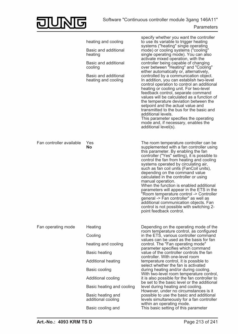
Art.-No.: 4093 KRM TS D
heating and cooling
Basic and additional heating
Basic and additional cooling
Basic and additional heating and cooling
specify whether you want the controller to use its variable to trigger heating systems ("heating" single operating mode) or cooling systems ("cooling" single operating mode). You can also activate mixed operation, with the controller being capable of changing over between "Heating" and "Cooling" either automatically or, alternatively, controlled by a communication object.In addition, you can establish two-level control operation to control an additional heating or cooling unit. For two-level feedback control, separate command values will be calculated as a function of the temperature deviation between the setpoint and the actual value and transmitted to the bus for the basic and additional levels.This parameter specifies the operating mode and, if necessary, enables the additional level(s).
Fan controller available YesNo
The room temperature controller can be supplemented with a fan controller using this parameter. By enabling the fan controller ("Yes" setting), it is possible to control the fan from heating and cooling systems operated by circulating air, such as fan coil units (FanCoil units), depending on the command value calculated in the controller or using manual operation.When the function is enabled additional parameters will appear in the ETS in the "Room temperature control -> Controller general -> Fan controller" as well as additional communication objects. Fan control is not possible with switching 2-point feedback control.
Fan operating mode Heating
Cooling
heating and cooling
Basic heating
Additional heating
Basic cooling
Additional cooling
Basic heating and cooling
Basic heating and additional cooling
Basic cooling and
Depending on the operating mode of the room temperature control, as configured in the ETS, various controller command values can be used as the basis for fan control. The "Fan operating mode" parameter specifies which command value of the controller controls the fan controller. With one-level room temperature control, it is possible to select whether the fan is activated during heating and/or during cooling. With two-level room temperature control, it is also possible for the fan controller to be set to the basic level or the additional level during heating and cooling. However, under no circumstances is it possible to use the basic and additional levels simultaneously for a fan controller within an operating mode.This basic setting of this parameter
Page 213 of 241
Software "Continuous controller module 3gang 146A11" Parameters
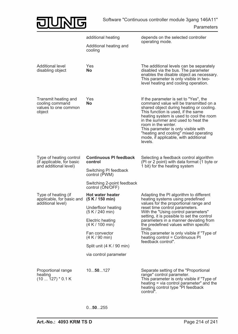
Art.-No.: 4093 KRM TS D
additional heating
Additional heating and cooling
depends on the selected controller operating mode.
Additional level disabling object
YesNo
The additional levels can be separately disabled via the bus. The parameter enables the disable object as necessary.This parameter is only visible in two-level heating and cooling operation.
Transmit heating and cooling command values to one common object
YesNo
If the parameter is set to "Yes", the command value will be transmitted on a shared object during heating or cooling. This function is used, if the same heating system is used to cool the room in the summer and used to heat the room in the winter.This parameter is only visible with "heating and cooling" mixed operating mode, if applicable, with additional levels.
Type of heating control(if applicable, for basic and additional level)
Continuous PI feedback control
Switching PI feedback control (PWM)
Switching 2-point feedback control (ON/OFF)
Selecting a feedback control algorithm (PI or 2 point) with data format (1 byte or 1 bit) for the heating system
Type of heating (if applicable, for basic and additional level)
Hot water heater (5 K / 150 min)
Underfloor heating (5 K / 240 min)
Electric heating (4 K / 100 min)
Fan convector (4 K / 90 min)
Split unit (4 K / 90 min)
via control parameter
Adapting the PI algorithm to different heating systems using predefined values for the proportional range and reset time control parameters.With the "Using control parameters" setting, it is possible to set the control parameters in a manner deviating from the predefined values within specific limits.This parameter is only visible if "Type of heating control = Continuous PI feedback control".
Proportional range heating(10 ... 127) * 0.1 K
10...50...127 Separate setting of the "Proportional range" control parameter.This parameter is only visible if "Type of heating = via control parameter" and the heating control type "PI feedback control".
0...50...255
Page 214 of 241
Software "Continuous controller module 3gang 146A11" Parameters
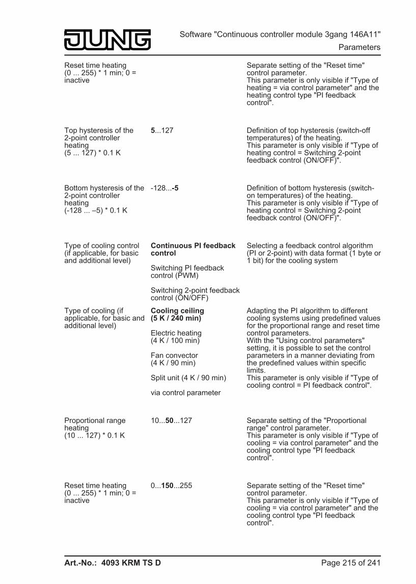
Art.-No.: 4093 KRM TS D
Reset time heating(0 ... 255) * 1 min; 0 = inactive
Separate setting of the "Reset time" control parameter.This parameter is only visible if "Type of heating = via control parameter" and the heating control type "PI feedback control".
Top hysteresis of the 2-point controller heating(5 ... 127) * 0.1 K
5...127 Definition of top hysteresis (switch-off temperatures) of the heating.This parameter is only visible if "Type of heating control = Switching 2-point feedback control (ON/OFF)".
Bottom hysteresis of the 2-point controller heating(-128 ... –5) * 0.1 K
-128...-5 Definition of bottom hysteresis (switch-on temperatures) of the heating.This parameter is only visible if "Type of heating control = Switching 2-point feedback control (ON/OFF)".
Type of cooling control(if applicable, for basic and additional level)
Continuous PI feedback control
Switching PI feedback control (PWM)
Switching 2-point feedback control (ON/OFF)
Selecting a feedback control algorithm (PI or 2-point) with data format (1 byte or 1 bit) for the cooling system
Type of cooling (if applicable, for basic and additional level)
Cooling ceiling (5 K / 240 min)
Electric heating (4 K / 100 min)
Fan convector (4 K / 90 min)
Split unit (4 K / 90 min)
via control parameter
Adapting the PI algorithm to different cooling systems using predefined values for the proportional range and reset time control parameters.With the "Using control parameters" setting, it is possible to set the control parameters in a manner deviating from the predefined values within specific limits.This parameter is only visible if "Type of cooling control = PI feedback control".
Proportional range heating(10 ... 127) * 0.1 K
10...50...127 Separate setting of the "Proportional range" control parameter.This parameter is only visible if "Type of cooling = via control parameter" and the cooling control type "PI feedback control".
Reset time heating(0 ... 255) * 1 min; 0 = inactive
0...150...255 Separate setting of the "Reset time" control parameter.This parameter is only visible if "Type of cooling = via control parameter" and the cooling control type "PI feedback control".
Page 215 of 241
Software "Continuous controller module 3gang 146A11" Parameters
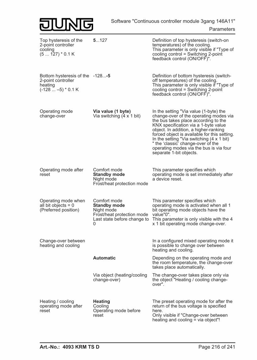
Art.-No.: 4093 KRM TS D
Top hysteresis of the 2-point controller cooling(5 ... 127) * 0.1 K
5...127 Definition of top hysteresis (switch-on temperatures) of the cooling.This parameter is only visible if "Type of cooling control = Switching 2-point feedback control (ON/OFF)".
Bottom hysteresis of the 2-point controller heating(-128 ... –5) * 0.1 K
-128...-5 Definition of bottom hysteresis (switch-off temperatures) of the cooling.This parameter is only visible if "Type of cooling control = Switching 2-point feedback control (ON/OFF)".
Operating mode change-over
Via value (1 byte)Via switching (4 x 1 bit)
In the setting "Via value (1-byte) the change-over of the operating modes via the bus takes place according to the KNX specification via a 1-byte value object. In addition, a higher-ranking forced object is available for this setting.In the setting "Via switching (4 x 1 bit)" the ‘classic’ change-over of the operating modes via the bus is via four separate 1-bit objects.
Operating mode after reset
Comfort modeStandby modeNight modeFrost/heat protection mode
This parameter specifies which operating mode is set immediately after a device reset.
Operating mode when all bit objects = 0(Preferred position)
Comfort modeStandby modeNight modeFrost/heat protection modeLast state before change to 0
This parameter specifies which operating mode is activated when all 1 bit operating mode objects have the value"0".This parameter is only visible with the 4 x 1 bit operating mode change-over.
Change-over between heating and cooling
In a configured mixed operating mode it is possible to change over between heating and cooling.
Automatic Depending on the operating mode and the room temperature, the change-over takes place automatically.
Via object (heating/cooling change-over)
The change-over takes place only via the object "Heating / cooling change-over".
Heating / cooling operating mode after reset
HeatingCoolingOperating mode before reset
The preset operating mode for after the return of the bus voltage is specified here.Only visible if "Change-over between heating and cooling = via object"!
Page 216 of 241
Software "Continuous controller module 3gang 146A11" Parameters
Art.-No.: 4093 KRM TS D
Automatic heating/cooling change-over transmission
On changing the operating mode
On changing the output value
Here, it is possible to specify when a telegram is transmitted automatically onto the bus via the object "Heating / cooling change-over".Only visible if "Change-over between heating and cooling = automatic".
Cyclical transmission heating/cooling change-over(0...255) * 1 min; 0 = inactive
0...255 This parameter specifies whether the current object status of the "Heating / cooling change-over" object should be output cyclically to the bus on an automatic change-over. The cycle time can be set here. The "0" setting deactivates the periodic transmission of the object value.Only visible if "Change-over between heating and cooling = automatic".
h Room temperature control -> Controller general -> Fan controller
Number of fan levels No fan levels1 fan level2 fan levels3 fan levels4 fan levels5 fan levels6 fan levels7 fan levels8 fan levels
The fan controller of the room temperature controller supports up to 8 fan level outputs, for which the actually used number of levels (1...8) is set using this parameter.
Fan levelchange-over via
via switching objects (3 x 1 bit)
via value object (1-byte)
Depending on the data format of the objects of the controlled actuators, the change-over between the fan levels can either take place via up to 8 separate 1-bit objects or, alternatively, via a one 1-byte object. The "Fan level change-over via" parameter defines the data format of the controller. With the 1-bit objects, each fan level discreetly receives its own object. With the 1-byte object, the active fan level is expressed by a value ("0" = Fan OFF / "1" = Level 1 / "2" = Level 2 / "3" = Level 3 / etc.).
Fan OFF threshold value -> Level 1,* 1 %
0...1...100 In automatic operation, the command value of the controller is used internally in the device for automatic control of the fan levels. As a transition between the levels, there are threshold values, defined according to the command value of the controller, which can be set here. If the command value exceeds the threshold value of a level, the appropriate level is activated. If the command value sinks below a threshold value, minus the configured hysteresis, then the change-over takes place into the next lowest fan level.
Page 217 of 241
Software "Continuous controller module 3gang 146A11" Parameters
Art.-No.: 4093 KRM TS D
Fan level 1 threshold value -> Level 2,* 1 %
0...30...100
Fan level 2 threshold value -> Level 3,* 1 %
0...60...100
Fan level 3 threshold value -> Level 4,* 1 %
0...90...100
Fan level 4 threshold value -> Level 5,* 1 %
0...100
Fan level 5 threshold value -> Level 6,* 1 %
0...100
Fan level 6 threshold value -> Level 7,* 1 %
0...100
Fan level 7 threshold value -> Level 8,* 1 %
0...100
Hysteresis between threshold values,*1%
1...3...50 If the command value of the room temperature controller has undershot the threshold value minus the hysteresis, the fan controller switches back to the previous level.
Waiting time for level change-over*0.1 s
1...2...255 Due to fan motors' inertia, as a rule there is a limit to how short the time intervals for switching the fan levels can be, i.e. there is a limit to how quickly the fan speed can be varied. If the fan controller is working in automatic mode, the settable "Waiting time on level change-over" is maintained on change-over of the levels.
Level limit (max. fan level)
No level limitFan level 1Fan level 2Fan level 3Fan level 4Fan level 5Fan level 6Fan level 7Fan level 8
To reduce the fan noise of a fan coil, the fan level limit can be activated. The level limit reduces the sound emissions by limiting the maximum fan level to a fan level value configured here (limitation level). The limit can be switched on and off using the "Fan, level limit" 1-bit object and thus activated as necessary.
The parameter "Level limit" is not checked for plausibility in the ETS, meaning that an implausible parameterisation is possible. For this reason, care should be taken to ensure that there is no limit level in the configuration which is higher than the actual fan levels. If a higher limit level is configured, then the limit has no effect.
Page 218 of 241
Software "Continuous controller module 3gang 146A11" Parameters
Art.-No.: 4093 KRM TS D
Behaviour on forced position
No forced positionFan level 1Fan level 2Fan level 3Fan level 4Fan level 5Fan level 6Fan level 7Fan level 8Fan level OFF
The controller provides the option of activating a forced fan position via the bus. With an active forced position, the fan levels can neither be controlled nor switched over in either automatic or manual mode. The fan remains in the forced state until the forced position is removed using the bus. In this manner, it is possible to switch the fan to a locked and controlled state, for example for servicing purposes.
As soon as the forced position is activated, the controller jumps to the fan level configured in this parameter without any waiting time. The fan can also be completely switched off.
Object interpretation, automatic/manual fan control
0=Automatic mode,1=Manual mode
1=Automatic mode,0=Manual mode
The parameter specifies the polarity of the object for the change-over between automatic and manual fan control. Automatic mode is always active after a device reset.
Fan level on change-over to manual
No changeFan level 1Fan level 2Fan level 3Fan level 4Fan level 5Fan level 6Fan level 7Fan level 8Fan level OFF
On change-over from automatic operation to manual operation, this parameter then decides whether the fan level most recently set in automatic operation is maintained, the fan is switched off or a defined fan level is set. The parameter "Fan level on change-over to manual" is not checked for plausibility in the ETS, meaning that an implausible parameterisation is possible. For this reason, care should be taken to ensure that there is no level in the configuration which is higher than the actual fan levels. If a level which does not exist is to be configured for the change-over to manual control, then the fan controller changes over to the maximum possible level when changing over to manual operation.
Heating fan run-on time,*0.1 s, 0=Inactive
0...255 If the fan is switched-off in automatic or manual operation, it runs on for the time configured at this point, provided that a factor of more than "0" is set. This parameter applies to the controller operating mode "Heating" (if necessary, in the basic and additional levels).
Cooling fan run-on time,*0.1 s, 0=Inactive
0...255 If the fan is switched-off in automatic or manual operation, it runs on for the time
Page 219 of 241
Software "Continuous controller module 3gang 146A11" Parameters
Art.-No.: 4093 KRM TS D
configured at this point, provided that a factor of more than "0" is set. This parameter applies to the controller operating mode "Cooling" (if necessary, in the basic and additional levels).
Fan protection YesNo
The fan protection function allows the fan of a fan coil unit, which has not been active for some time, to be temporarily switched to the maximum level. In this way, the controller fan motors can be protected against stiffness. In addition, the fan blades and the heat exchanger of the fan coil unit are protected against dust against dust.If the fan protection is to be used, it must be enabled using the "Yes" setting at this point.
Start-up using level Fan level OFFFan level 1Fan level 2Fan level 3Fan level 4Fan level 5Fan level 6Fan level 7Fan level 8
The fan can, if it was switched off before and should now start up, be switched on at a defined switch-on level. This switch-on level can be any of the available fan levels, and is set using this parameter. The switch-on level is usually one of the higher fan levels of a blower convector. The switch-on level remains active for the "Waiting time on level change-over" configured in the ETS.
The parameter "Start-up via level" is not checked for plausibility in the ETS, meaning that an implausible parameterisation is possible. For this reason, care should be taken to ensure that there is no switch-on level in the configuration which is higher than the actual fan levels. The fan controller automatically corrects a faulty parameterisation by activating level 1 for the start-up, meaning that the fan starts up normally without a switch-on level.
Command value is 0%, until internal command value is greater than,*1%
1...100 The command value evaluated by the fan controller in automatic operation can be optionally limited by this parameter in the bottom command value range.
Command value is 100%, as soon as internal command value is greater than,*1%
1...99...100 The command value evaluated by the fan controller in Automatic mode can be optionally limited by this parameter in the top command value range.
Command value offset,*1%
0... 100 The command value evaluated by the fan controller in Automatic mode can be
Page 220 of 241
Software "Continuous controller module 3gang 146A11" Parameters
Art.-No.: 4093 KRM TS D
optionally raised by the static offset configured here. Should the calculation produce a value of over 100 %, then the command value is limited to the maximum value.
h Room temperature control -> Controller general -> Command value and status output
Automatic transmission on change by(0...100) * 1 %; 0 = inactive
0...3...100 This parameter determines the size of the command value change that will automatically transmit continuous command value telegrams via the command value objects. Thus this parameter only affects command values which are configured to "Continuous PI feedback control" and to the 1 byte additional command value objects of the "Switching PI feedback control (PWM)".
Cycle time of the switching command value(1...255) * 1 min
1...15...255 This parameter specifies the cycle time for the pulse width modulated command value (PWM). Thus this parameter only affects command values which are configured to "Switching PI feedback control (PWM)".
Cycle time for automatic transmission(0...255) * 1 min; 0 = inactive
0...10...255 This parameter determines the time interval for the cyclical transmission of the command values via the command value objects. This parameter only affects command values which are configured to "Continuous PI feedback control" or "Switching PI feedback control (PWM)".
Output of the heating command value
Inverted (under current, this means closed)
Normal (under current, this means opened)
At this point, it is possible to specify whether the command value telegram for heating is output normally or in inverted form.This parameter is only visible if the operating mode "Heating" or "Heating and cooling" is configured and not two-level operation.
Output of the heating basic level command value
Inverted (under current, this means closed)
Normal (under current, this means opened)
At this point, it is possible to specify whether the command value telegram for the heating basic level is output normally or in inverted form.This parameter is only visible if the operating mode "Heating" or "Heating and cooling" is configured along with two-level operation.
Page 221 of 241
Software "Continuous controller module 3gang 146A11" Parameters
Art.-No.: 4093 KRM TS D
Output of the heating additional level command value
Inverted (under current, this means closed)
Normal (under current, this means opened)
At this point, it is possible to specify whether the command value telegram for the heating additional level is output normally or in inverted form.This parameter is only visible if the operating mode "Heating" or "Heating and cooling" is configured along with two-level operation.
Output of the cooling command value
Inverted (under current, this means closed)
Normal (under current, this means opened)
At this point, it is possible to specify whether the command value telegram for cooling is output normally or in inverted form.This parameter is only visible if the operating mode "Cooling" or "Heating and cooling" is configured and not two-level operation.
Output of the cooling basic level command value
Inverted (under current, this means closed)
Normal (under current, this means opened)
At this point, it is possible to specify whether the command value telegram for the cooling basic level is output normally or in inverted form.This parameter is only visible if the operating mode "Cooling" or "Heating and cooling" is configured along with two-level operation.
Output of the cooling additional level command value
Inverted (under current, this means closed)
Normal (under current, this means opened)
At this point, it is possible to specify whether the command value telegram for the cooling additional level is output normally or in inverted form.This parameter is only visible if the operating mode "Cooling" or "Heating and cooling" is configured along with two-level operation.
Heating message YesNo
Depending on the set operating mode, a separate object can be used to signal whether the controller is currently demanding heating energy and is thus actively heating. The "Yes" setting here enables the message function for heating.
Cooling message YesNo
Depending on the set operating mode, a separate object can be used to signal whether the controller is currently demanding cooling energy and is thus actively cooling. The "Yes" setting here enables the message function for cooling.
Controller status No status The controller can output its current operating status. A distinction is made
Page 222 of 241
Software "Continuous controller module 3gang 146A11" Parameters
Art.-No.: 4093 KRM TS D
Controller general
Transmit individual state
whether the status signal is transmitted to the bus via a 1 byte telegram or a 1 bit telegram.In the "Controller general" setting, various status signals of the controller are output as a collective signal via an object of 1 byte. Each bit represents one piece of status information.In the setting "Transmit individual status", the controller status is transmitted onto the bus as a single 1 bit status signal. The "Single status" parameter specifies the status information to be transmitted individually.
Single status Comfort modeActive Standby mode activatedNight mode activatedFrost/heat protection activeController disabledHeating / coolingController inactiveFrost alarm
Here, the status information is defined, which is to be transmitted onto the bus as the controller status.This parameter is only visible if the parameter "Controller status" is set to "Transmit single status".
h Room temperature control -> Controller general -> Setpoints
Basic temperature after reset(7 ... 40) * 1 °C
7...21...40 This parameter defines the temperature value to be applies as the basic setpoint after commissioning by the ETS. All the temperature setpoints are derived from the basic setpoint.
Permanently apply change to basic setpoint shift
NoYes
In addition to the setting of individual temperature setpoints via the ETS, the user is able to shift the basic setpoint within a settable range anytime via local control or via the basic setpoint object, either using the display buttons or with the "Setpoint shift" push-button function, if this is configured to a function button of the pushbutton sensor. Whether a basic setpoint shifting only affects the currently active operating mode or whether it influences all other setpoint temperatures of the remaining operating modes is determined by this parameter.
In the "Yes" setting, the shift of the basic setpoint carried out affects all operating modes. The shifting is maintained even after change-over of the operating mode or the heating/cooling mode or readjusting the basic setpoint.In the "No" setting, the basic setpoint shift carried out is in effect for only as long as the operating mode or heating/cooling mode has not changed or the basic setpoint is maintained. Otherwise
Page 223 of 241
Software "Continuous controller module 3gang 146A11" Parameters
Art.-No.: 4093 KRM TS D
the setpoint shift will be reset to "0".
Changing of the basic temperature setpoint value via bus
DeactivatedApprove
Here, it is possible to specify if it is possible to change the basic setpoint via the bus. In the "Approve" setting, the "Basic setpoint" object is visible in the ETS.
Accept change of the basic temperature setpoint value permanently
NoYes
One has to distinguish between two cases, defined by this parameter, if the basic setpoint has been modified (via local control or via the object):In the "Yes" setting, the controller saves the basic setpoint permanently in the EEPROM. The newly adjusted value will overwrite the basic temperature originally configured via the ETS after a reset! This is the only way to keep the adjusted basic setpoint even after change-over of the operating mode or after a reset.
In the "No" setting, the basic setpoint, which was set on the room temperature controller or received via the object, stays only temporarily active in the current operating mode. In case of a bus voltage failure or following a change-over to another operating mode (e.g. Comfort followed by Standby), the basic setpoint set via local control or received via the object will be discarded and replaced by the value which was originally configured in the ETS.
Frost protection setpoint temperature(7...40) * 1 °C
7...40 This parameter specifies the setpoint temperature for frost protection. The parameter is only visible in "Heating" or "Heating and cooling" operating modes (if necessary with additional levels).
Heat protection setpoint temperature(7...45) * 1 °C
7...35...45 This parameter specifies the setpoint temperature for heat protection. The parameter is only visible in "Cooling" or "Heating and cooling" operating modes (if necessary with additional levels).
Deadband position SymmetricalAsymmetrical
The comfort setpoint temperatures for "Heating and cooling" operating modes are derived from the basic setpoint in consideration of the adjusted deadband. The deadband (temperature zone for which there is neither heating nor
Page 224 of 241
Software "Continuous controller module 3gang 146A11" Parameters
Art.-No.: 4093 KRM TS D
cooling) is the difference between the comfort setpoint temperatures.Symmetrical setting: the deadband preset in the ETS plug-in is divided in two parts at the basic setpoint. The comfort setpoint temperatures are derived directly from the basic setpoint resulting from the half deadband (Basic setpoint - 1/2 deadband = Heating comfort temperature or Basic setpoint + 1/2 deadband = Cooling comfort temperature).
Asymmetrical setting: with this setting the comfort setpoint temperature for heating equals the basic setpoint! The preset deadband is effective only from the basic setpoint in the direction of comfort temperature for cooling. Thus the comfort setpoint temperature for cooling is derived directly from the comfort setpoint for heating.The parameter is only visible in "Heating and cooling" operating modes (if necessary with additional levels).
Deadband between heating and cooling (0...127) * 0.1 K
0...20...127 The comfort setpoint temperatures for heating and cooling are derived from the basic setpoint in consideration of the adjusted deadband. The deadband (temperature zone for which there is neither heating nor cooling) is the difference between the comfort setpoint temperatures. It is set using this parameter.The parameter is only visible in "Heating and cooling" operating modes (if necessary with additional levels).
Difference between basic and additional levels(0...127) * 0.1 K
0...20...127 In a two-level control mode, it is necessary to determine the temperature difference to the basic level with which the additional level is to be incorporated into the feedback control. This parameter defines the level spacing.The parameter can only be seen in two-level control operation.
Transmission at setpoint temperature change by(0...255) * 0.1 K
0...1...255 Determines the size of the value change required to automatically transmit the current value via the "Setpoint temperature" object. In the "0" setting, the setpoint temperature is not transmitted automatically when there is a change.
Page 225 of 241
Software "Continuous controller module 3gang 146A11" Parameters
Art.-No.: 4093 KRM TS D
Cyclical transmission of setpoint temperature(0...255) * 1 min; 0 = inactive
0...255 This parameter determines whether the setpoint temperature is to be transmitted periodically via the "Setpoint temperature" object. Definition of the cycle time by this parameter In the "0" setting, the setpoint temperature is not transmitted automatically cyclically.
Increment of the 4-level setpoint shift
0.5 K1.0 K1.5 K2.0 K
This parameter defines the value of a level of the basic setpoint shift. The basic setpoint can be shifted by up to 4 levels.
Temporary setpoint display for setpoint shift?
YesNo
Optionally the setpoint of the respective current operating mode can be shown automatically in the display if a setpoint shift is performed using the buttons of the device ("Setpoint shift" button function). The setpoint temperature is then indicated temporarily for 5 s in °C or °F, and overwrites the normal display (time, actual temperature, etc.). The setpoint display for a setpoint shift is activated when this parameter is set to "Yes". With the setting "No" the temporary display is inactive, meaning that in case of a setpoint shift only the line graphic of the display is activated, but the temperature value is not also displayed automatically.
Lower the setpoint temperature during Standby operating mode (heating) (-128...0) * 0.1 K
-128...-20...0 The value by which the standby setpoint temperature for heating is lowered compared to the heating comfort temperature.The parameter is only visible in "Heating" or "Heating and cooling" operating modes (if necessary with additional levels).
Lower the setpoint temperature during Night mode (heating) (-128...0) * 0.1 K
-128...-40...0 The value by which the night setpoint temperature for heating is lowered compared to the heating comfort temperature.The parameter is only visible in "Heating" or "Heating and cooling" operating modes (if necessary with additional levels).
Raise the setpoint temperature during Standby operating
0...20...127 The value by which the standby setpoint temperature for cooling is lowered compared to the cooling comfort temperature.
Page 226 of 241
Software "Continuous controller module 3gang 146A11" Parameters
Art.-No.: 4093 KRM TS D
mode (cooling) (0...127) * 0.1 K
The parameter is only visible in "Cooling" or "Heating and cooling" operating modes (if necessary with additional levels).
Raise the setpoint temperature during Night mode (cooling) (0...127) * 0.1 K
0...40...127 The value by which the night temperature for cooling is lowered compared to the cooling comfort temperature.The parameter is only visible in "Cooling" or "Heating and cooling" operating modes (if necessary with additional levels).
Setpoint temperature limit in cooling operation
No limit
Only difference to outdoor temperature
Only max. setpoint temperature
Max. setpoint and difference to outdoor temperature
Optionally, the setpoint temperature limit can be enabled here, which is only effective in cooling operation. If necessary, the controller limits the setpoint temperature to specific values and prevents an adjustment beyond the limits.
"Only difference to outdoor temperature" setting, the outdoor temperature is monitored and compared to the active setpoint temperature in this setting. The specification of the maximum temperature difference to the outdoor temperature is made using the "Difference to outdoor temperature in cooling mode" parameter. If the outdoor temperature rises above 32 °C, then the controller activates the setpoint temperature limit. It then permanently monitors the outdoor temperature and raises the setpoint temperature so that is beneath the outdoor temperature by the amount configured. Should the outdoor temperature continue rise, the controller raises the setpoint temperature until the required difference to the outdoor temperature is achieved, or, at most, the heat protection temperature. It is then not possible to undershoot the raised setpoint, e.g. by changing the basic setpoint change. The change to the setpoint temperature limit is temporary. It only applies for as long as the outdoor temperature exceeds 32 °C.
"Only max. setpoint temperature" setting: In this setting, no setpoint temperatures are permitted in Cooling mode related to the Comfort, Standby and Night modes, which are greater than the maximum setpoints configured in the ETS. The maximum temperature setpoint is specified by the "Max. setpoint temperature in cooling
Page 227 of 241
Software "Continuous controller module 3gang 146A11" Parameters
Art.-No.: 4093 KRM TS D
operation" parameter. With an active limit, no larger setpoint can be set in cooling operation, e.g. by a basic setpoint change or a setpoint shift. However, heat protection is not influenced by the setpoint temperature limit.
"Max. setpoint temperature and difference to outdoor temperature" setting: This setting is a combination of the two above-mentioned settings. In the downward direction, the setpoint temperature is limited by the maximum outdoor temperature difference, whilst in the upward direction, the limit is made by the maximum setpoint. The maximum setpoint temperature has priority over the outdoor temperature difference. This means that the controller keeps on raising the setpoint temperature upwards according to the difference to the outdoor temperature configured in the ETS until the maximum setpoint temperature or the heat protection temperature is exceeded. Then the setpoint is limited to the maximum value.
Activation of the setpoint temperature limit in cooling operation via object
NoYes
A setpoint limit enabled in the ETS can be activated or deactivated as necessary using a 1-bit object. For this, this parameter can be set to "Yes". In this case, the controller only takes the setpoint limit into account, if it has been enabled via the object "Cooling setpoint temp. limit" ("1" telegram). If the limitation is not enabled ("0" telegram), the cooling setpoint temperatures are not limited.This parameter is visible only if setpoint temperature monitoring is enabled.
Difference to outdoor temperature in cooling operation
1 K...6 K...15 K This parameter defines the maximum difference between the setpoint temperature in Comfort mode and the outdoor temperature with an active setpoint temperature limit.This parameter is visible only if setpoint temperature monitoring is enabled. However, this is only if the parameter "Setpoint temperature limit in cooling operation" is then set to "Only difference to outdoor temperature" or "Max. setpoint temperature and difference to outdoor temperature".
Max. setpoint temperature in cooling operation
20°C...26°C...35°C This parameter defines the maximum setpoint temperature in Comfort mode with an active setpoint temperature limit.
Page 228 of 241
Software "Continuous controller module 3gang 146A11" Parameters
Art.-No.: 4093 KRM TS D
This parameter is visible only if setpoint temperature monitoring is enabled. However, this is only if the parameter "Setpoint temperature limit in cooling operation" is then set to "Only max. setpoint temperature" or "Max. setpoint temperature and difference to outdoor temperature".
h Room temperature control -> Controller general -> Second operating level
Changing the basic temperature
DisabledEnabled
Here it is possible to specify whether the basic temperature can be changed in the menu of the second operating level ("Enabled" setting). With "Disabled" the basic temperature is only displayed without being able to change it.It should be noted that the visibility of the setpoint temperatures in the second operating level ("Continuous controller" menu) depends on the parameter setting in the area "General -> Second operating level"!
Changing the setpoint temperature during standby mode (heating)
DisabledEnabled
Here it is possible to specify whether the setpoint temperature of the "Standby" operating mode for heating mode can be changed in the menu of the second operating level ("Enabled" setting). With "Disabled" the setpoint temperature is only displayed without being able to change it.It should be noted that the visibility of the setpoint temperatures in the second operating level ("Continuous controller" menu) depends on the parameter setting in the area "General -> Second operating level"!
Changing the setpoint temperature during standby mode (heating)
DisabledEnabled
Here it is possible to specify whether the setpoint temperature of the "Standby" operating mode for cooling mode can be changed in the menu of the second operating level ("Enabled" setting). With "Disabled" the setpoint temperature is only displayed without being able to change it.It should be noted that the visibility of the setpoint temperatures in the second operating level ("Continuous controller" menu) depends on the parameter setting in the area "General -> Second operating level"!
Changing the setpoint temperature during night mode (heating)
DisabledEnabled
Here it is possible to specify whether the setpoint temperature of the "Night" operating mode for heating mode can be changed in the menu of the second
Page 229 of 241
Software "Continuous controller module 3gang 146A11" Parameters
Art.-No.: 4093 KRM TS D
operating level ("Enabled" setting). With "Disabled" the setpoint temperature is only displayed without being able to change it.It should be noted that the visibility of the setpoint temperatures in the second operating level ("Continuous controller" menu) depends on the parameter setting in the area "General -> Second operating level"!
Changing the setpoint temperature during night mode (cooling)
DisabledEnabled
Here it is possible to specify whether the setpoint temperature of the "Night" operating mode for cooling mode can be changed in the menu of the second operating level ("Enabled" setting). With "Disabled" the setpoint temperature is only displayed without being able to change it.It should be noted that the visibility of the setpoint temperatures in the second operating level ("Continuous controller" menu) depends on the parameter setting in the area "General -> Second operating level"!
h Room temperature measurement -> Controller functionality
Presence detection Presence buttonMotion detector
In the "Presence button" setting, presence detection takes place using a button on the device or via the presence object (e.g. other pushbutton sensors). When the presence button is pressed, the comfort extension is activated. In the "Motion detector" setting, presence detection takes place using an external motion detector, coupled to the presence object. Comfort mode is recalled when a presence is detected. Comfort mode remains active until the motion detector ceases to detect movement. In this setting, a presence button on the device has no function.
Length of the comfort extension(0 .. 255) * 1 min; 0 = OFF
0...30...255 When the presence button is pressed, the controller switches to Comfort mode for the length of time specified here. When this time has elapsed, it switches back automatically. In the "0" setting, the comfort extension is switched off, meaning that it cannot be activated from Night or Frost/heat protection mode. In this case, the operating mode will not be changed, although the presence function has been activated.This parameter is only visible when presence detection is configured to "Presence button".
Page 230 of 241
Software "Continuous controller module 3gang 146A11" Parameters
Art.-No.: 4093 KRM TS D
Switch off controller (dew point operation)
NoVia bus
This parameter enables the "Disable controller" object. If the controller is disabled, there is no feedback control until enabled (command values = 0). An activated controller disable (dew point operation) is shown in the display.
Valve protection NoYes
Valve protection may be carried out periodically in order to prevent the addressed control valves of the heater or cooling system from becoming calcified or stuck. The "Yes" setting in this parameter activates valve protection.This type of protection is generally started not only for non-active command value outputs, i.e. for outputs which have not requested any heating or cooling energy over the past 24 hours. For these outputs, the controller will periodically set the command value to the maximum value once a day for a duration of approx. 5 minutes.
Underfloor heating temperature limit(Only effective in heating mode!)
Not presentPresent
The temperature limit can be activated in the controller in order to protect an underfloor heating system. If the temperature limit is enabled here ("Present" setting), the controller continuously monitors the floor temperature. Should the floor temperature exceed a specific limiting value on heating, the controller immediately switches the command value off, thus switching the heating off and cooling the system. Only when the temperature falls below the limiting value, minus a hysteresis of 1 K, will the controller add the most recently calculated command value.The floor temperature is fed to the controller using a separate object.It should be noted that the temperature limit only affects command values for heating. Thus, the temperature limit requires the controller operating modes "Heating" or "Heating and cooling".
Effect on Heating, basic levelHeating, additional level
The temperature limit can also be used in a two-level feedback control with basic and additional levels. It must then be specified here to which level the limit shall apply. Either the basic level or to the additional level for heating can be limited.This parameter can only be set in two-level control operation.
Page 231 of 241
Software "Continuous controller module 3gang 146A11" Parameters
Art.-No.: 4093 KRM TS D
Maximum temperature, underfloor heating * 1 °C
20...30...70 The maximum limit temperature which the underfloor heating system may reach is specified here. If this temperature is exceeded, the controller switches the underfloor heating system off using the command value. As soon as the floor temperature has fallen 1 K under the limit temperature, the controller switches the command value on again, assuming that this is intended in the control algorithm. The 1 K hysteresis is fixed and cannot be changed.
Page 232 of 241
Software "Continuous controller module 3gang 146A11" Parameters
Art.-No.: 4093 KRM TS D
4.2.5.5 Parameters for the display
Description Values Comment h Display
Backlighting Always off
Always on
Switch on through button-press
Switch on in night mode
Switch on through button-press or Night mode
Switch on through switching objectSwitch on through inverted switching object
Switch on through button-press or switching object
Switch on through button-press or inv. switching object
Switch on through value object (0%...100%)
Switch on through button-press or value object
The backlighting can be permanently on or off or alternatively be switched according to events. If the lighting is switched on by pressing a control surface (rocker or button), the device switches the lighting off automatically when the switch-off time configured in the ETS elapses. The switch-off time is retriggered each time a control surface is actuated.
If the lighting is to be switched on in the "Night" operating mode, the lighting remains switched on continuously when night mode is active. Switching on by pressing a button or via the operating mode "Night" always takes place using the brightness value configured in the ETS or specified locally in the second operating level.
When the backlighting is switched by the 1-bit communication object (alternatively to the 1-byte object), the lighting remains switched on continuously according to the switching value (not inverted: "0" = OFF / "1" = ON; inverted: "0" = ON" / "1" = OFF). Here the switch-on brightness is defined by the display brightness value configured in the ETS or specified locally in the second operating level.
In the case of activation by the value object the lighting is dimmed in accordance with the received value ("1...254") or actuated to the maximum ("255"). The value "0" switches the lighting off completely.
Lighting activation by operating a control surface area can be combined with switching or dimming via the corresponding objects. In this case the control via the communication objects has a higher priority. The lighting is switched on automatically by pressing a control surface, and is only switched off again when the switch-off time configured in the ETS elapses, if the lighting is to be switched off via the corresponding communication object (object value "OFF" or "0"). Switching on by pressing a button always takes place using the brightness value configured in the ETS or specified locally in the second operating level. In addition, the lighting can also be switched or dimmed by the communication objects, independently of operation on the
Page 233 of 241
Software "Continuous controller module 3gang 146A11" Parameters
Art.-No.: 4093 KRM TS D
device. In this case, the lighting is not switched off automatically when the time has elapsed. The switch-off can then only take place using a switch-off telegram in accordance with the normal or inverted telegram polarity or via a value = "0" It is not possible to switch-off backlighting switched on by operation early using a bus telegram.
Brightness of the backlighting (10...100%)
10...70...100 This parameter defines the brightness of the LCD backlighting. The value configured here can be overwritten after commissioning of the device locally in the second operating level via the setting "Display brightness".
Automatic switch-off after
15 s30 s45 s1.0 min1.5 min…1 h
The backlighting of the display is switched off automatically after the time set here, if it has been switched on by a button-press.This parameter is only visible when the backlighting can be switched on by button-press.
Number of pieces of display information
1 piece of display information2 pieces of display information3 pieces of display information4 pieces of display information
In addition to the symbols, it is possible to use the numeric display to show up to four display functions in the display. This means that is possible to indicate the time, the setpoint temperature, the actual temperature or the outdoor temperature.It is possible to configure how much of this information is actually shown in the display using this parameter in the ETS. For each piece of display information, additional parameter nodes are then shown in the ETS.
Cyclical changeover of display information(1 ... 60 s)
1...10...60 This parameter specifies after how long a changeover of display information takes place on the display.
Display pictogram frames
NoYes
The symbols can be surrounded by square pictogram frames in the display, thus providing a graphical delimitation. The pictograms serve as placeholders for non-illuminated symbols.If the pictogram frames are not displayed ("No" setting), then only the active symbols are visible in the display. If the pictogram frames are displayed ("Yes" setting), then the frames are always visible and the active symbols are illuminated inside the corresponding frames.
Page 234 of 241
Software "Continuous controller module 3gang 146A11" Parameters
Art.-No.: 4093 KRM TS D
h Display -> Indication 1
Display information 1 Time
Setpoint temperature
Actual temperature
Outdoor temperature
Here, it is possible to select which piece of information is to be Indicated on the display.This parameter presetting depends on the selected display information.
h Display -> Indications 2, 3, 4 (see Indication 1)
Page 235 of 241
Software "Continuous controller module 3gang 146A11" Parameters
Art.-No.: 4093 KRM TS D
4.2.5.6 Parameter on scene function
Description Values Comment h Scene
Scene function ? Yes
No
The device can internally handle eight scenes with eight actuator groups. This parameter activates the scene function and the other parameters and communication objects, if needed.
Overwrite scene values during ETS download
Yes
No
If the values of the actuator groups that have been changed on site by the used are to be reset to the values preset in the ETS during an application download by the ETS, the setting "Yes" must be chosen. If "No" is selected, the ETS values will not overwrite the scene values stored in the pushbutton sensor, if any.
Scene 1 Recall via extension object with scene number
1 ... 64 If the internal scenes are to be recalled via the extension object, a definite number is required for each of them.This parameter serves to specify the extension number of the first scene.
Scene 2 Recall via extension object with scene number
1...2 ... 64 If the internal scenes are to be recalled via the extension object, a definite number is required for each of them.This parameter serves to specify the extension number of the second scene.
Scene 3 Recall via extension object with scene number
1...3 ... 64 If the internal scenes are to be recalled via the extension object, a definite number is required for each of them.This parameter serves to specify the extension number of the third scene.
Scene 4 Recall via extension object with scene number
1...4 ... 64 If the internal scenes are to be recalled via the extension object, a definite number is required for each of them.This parameter serves to specify the extension number of the fourth scene.
Scene 5 Recall via extension object with scene number
1...5 ... 64 If the internal scenes are to be recalled via the extension object, a definite number is required for each of them.This parameter serves to specify the extension number of the fifth scene.
1...6 ... 64
Page 236 of 241
Software "Continuous controller module 3gang 146A11" Parameters
Art.-No.: 4093 KRM TS D
Scene 6 Recall via extension object with scene number
If the internal scenes are to be recalled via the extension object, a definite number is required for each of them.This parameter serves to specify the extension number of the sixth scene.
Scene 7 Recall via extension object with scene number
1...7 ... 64 If the internal scenes are to be recalled via the extension object, a definite number is required for each of them.This parameter serves to specify the extension number of the seventh scene.
Scene 8 Recall via extension object with scene number
1...8 ... 64 If the internal scenes are to be recalled via the extension object, a definite number is required for each of them.This parameter serves to specify the extension number of the eighth scene.
h Scene output 1
Data type Switching
Value (0 … 255)
Value / position of Venetian blind (0 … 100%)
Selection of the data format of the scene output.
Scene 1Switching command
ON
OFF
The switching command of the first scene can be predefined here.This parameter is only visible if "Data type = Switching".
Scene 1Value (0 … 255)
0...255 The value of the first scene can be predefined here.This parameter is only visible if "Data type = Value (0...255)".
Scene 1Value / position of Venetian blind (0 … 100 %)
0...100 The value of the first scene can be predefined here.This parameter is only visible if "Data type = Value / Venetian blind (0...100%)".
Scene 1Allow save?
Yes
No
If the user is to be given the possibility of changing the value of the scene and of storing it while the system is running, this parameter must be set to "Yes".
Scene 1Allow transmission?
Yes
No
If the state of an actuator group is to remain unchanged during the recall of a scene, this parameter can be set to
Page 237 of 241
Software "Continuous controller module 3gang 146A11" Parameters
Art.-No.: 4093 KRM TS D
"No". In this case, the pushbutton sensor does not transmit a telegram via the scene output concerned during the recall of the scene. The scene output is deactivated for this scene.
Scene 1Transmit delay (1 … 1200 * 100 ms)(0 = deactivated)
0...1200 When the pushbutton sensor sends the telegrams to the various scene outputs, it can insert a presettable waiting time of 2 min. max. before each telegram. The bus load can be reduced by this. In this way, it is possible to have certain lighting switched on only after the shutters are really closed.If no delay is selected ("0" setting), the pushbutton sensor sends the output telegrams with maximum speed. With this setting it may happen in some cases that the telegram sequence is not compatible with output numbering.
Scenes 2 … 8 see scene 1!
h Scene output 2 ... 8 (see Scene output 1)
Page 238 of 241
Software "Continuous controller module 3gang 146A11" Parameters
5 Appendix
5.1 Index
2 2-point feedback control .. ............. 104, 110
A actual temperature .. ............................. 135adapter frame .. ...................................... 9Adapting .. ..................................... 108, 110Additional controller status .. ................. 140alarm messages .. .................................. 97Automatic operation .. ........................... 143Automatic transmission .. ...................... 138
B Backlighting .. ........................................ 165basic display .. ........................................ 16basic setpoint .. .............................. 128-129Basic setpoint shift .. ............................. 130Button arrangement .. ............................. 71Button configuration .. ............................. 67button evaluation .. ................................. 68
C Comfort extension .. .............................. 118Command value limiting values .. ......... 146Command value objects .. ..................... 137command value offset .. ........................ 146Commissioning .. .................................... 13communication objects .. ........................ 32continuous controller module .. ............... 9control algorithm .. ................................. 101Control surfaces .. .................................. 66Controller status .. ................................. 139
D Delivery state .. ..................................... 168dew point mode .. .................................. 148Display control surface .. ................... 15, 66Display information .. ............................. 163
E ETS configuration .. ................................ 31ETS search paths .. ................................ 27extension objects .. ............................... 151
F fan controller .. ...................................... 141Fan level limit .. ..................................... 145Fan protection .. .................................... 147Fitting .. ................................................... 9
Art.-No.: 4093 KRM TS D
Forced fan position .. ............................. 146
H Heating/cooling message .. ................... 100
I Installing the decorative control surfaces
.. 14
L LC display .. .......................................... 162
M manual operation .. ............................... 143mixed operating mode .. ......................... 99
O operating mode after a reset .. .............. 119Operating mode change-over .. ...... 88, 112operating modes .. .................................. 98Operation concept .. ............................... 68
P PI feedback control .. .................... 102, 108Presence button .. ................................. 153Presence function .. .............................. 118product database .. ................................. 31Pushbutton -> Button configuration .. .... 176Pushbutton sensor -> Button configuration -> Operation concept of continuous controller module
.. 176
Pushbutton sensor -> Button configuration -> Operation concept of expansion module
.. 177
R Room temperature measurement .. ...... 157
S Scene control .. ..................................... 159Scene definition .. .................................. 159scene recall .. ........................................ 159second operating level .. ......................... 17setpoint shift .. ....................................... 155Setpoint shift .. ................................ 89, 154setpoint temperature .. .......................... 133setpoint temperature limit .. ................... 127setpoint temperatures .. ........................ 120status LEDs .. ..................................... 15-16Storing scenes .. ................................... 160Switching PI feedback control .. ............ 102
Page 239 of 241
Appendix
Art.-No.: 4093 KRM TS D Page 240 of 241
Appendix
Switch-on level .. ................................... 144Symbols .. ............................................. 162
T temperature setpoints .. ........................ 130
U Underfloor heating temperature limit .. .. 136
V Valve protection .. ................................. 149
W window status .. ..................................... 118
Art.-No.: 4093 KRM TS D
ALBRECHT JUNG GMBH & CO. KG Volmestraße 1 D-58579 Schalksmühle
Telefon: +49.23 55.8 06-0 Telefax: +49.23 55.8 06-1 89 E-mail: [email protected] Internet: www.jung.de www.jung-katalog.de
Page 241 of 241
Appendix