inspire infrastructure for spatial information in...
TRANSCRIPT

INSPIRE Infrastructure for Spatial Information in Europe
D2.8.III.2 Data Specification on Buildings – Technical Guidelines
Title D2.8.III.2 INSPIRE Data Specification on Buildings – Technical Guidelines
Creator INSPIRE Thematic Working Group Buildings
Date 2013-12-10
Subject INSPIRE Data Specification for the spatial data theme Buildings
Publisher European Commission Joint Research Centre
Type Text
Description This document describes the INSPIRE Data Specification for the spatial data theme Buildings
Contributor Members of the INSPIRE Thematic Working Group Buildings
Format Portable Document Format (pdf)
Source
Rights Public
Identifier D2.8.III.2_v3.0
Language En
Relation Directive 2007/2/EC of the European Parliament and of the Council of 14 March 2007 establishing an Infrastructure for Spatial Information in the European Community (INSPIRE)
Coverage Project duration

INSPIRE Reference: D2.8.III.2_v3.0
TWG-BU Data Specification on Buildings 2013-12-10 Page II
Foreword How to read the document? This document describes the “INSPIRE data specification on Buildings – Technical Guidelines” version 3.0 as developed by the Thematic Working Group (TWG) BU using both natural and a conceptual schema language. The data specification is based on a common template
1 used for all data specifications, which has
been harmonised using the experience from the development of the Annex I, II and III data specifications. This document provides guidelines for the implementation of the provisions laid down in the draft Implementing Rule for spatial data sets and services of the INSPIRE Directive. It also includes additional requirements and recommendations that, although not included in the Implementing Rule, are relevant to guarantee or to increase data interoperability. Two executive summaries provide a quick overview of the INSPIRE data specification process in general, and the content of the data specification on Buildings in particular. We highly recommend that managers, decision makers, and all those new to the INSPIRE process and/or information modelling should read these executive summaries first. The UML diagrams (in Chapter 5) offer a rapid way to see the main elements of the specifications and their relationships. The definition of the spatial object types, attributes, and relationships are included in the Feature Catalogue (also in Chapter 5). People having thematic expertise but not familiar with UML can fully understand the content of the data model focusing on the Feature Catalogue. Users might also find the Feature Catalogue especially useful to check if it contains the data necessary for the applications that they run. The technical details are expected to be of prime interest to those organisations that are responsible for implementing INSPIRE within the field of Buildings, but also to other stakeholders and users of the spatial data infrastructure. The technical provisions and the underlying concepts are often illustrated by examples. Smaller examples are within the text of the specification, while longer explanatory examples and descriptions of selected use cases are attached in the annexes. In order to distinguish the INSPIRE spatial data themes from the spatial object types, the INSPIRE spatial data themes are written in italics.
The document will be publicly available as a ‗non-paper‘. It does not represent an official position of the European Commission, and as such cannot be invoked in the context of legal procedures.
Legal Notice Neither the European Commission nor any person acting on behalf of the Commission is responsible for the use which might be made of this publication.
1 The common document template is available in the ―Framework documents‖ section of the data
specifications web page at http://inspire.jrc.ec.europa.eu/index.cfm/pageid/2

INSPIRE Reference: D2.8.III.2_v3.0
TWG-BU Data Specification on Buildings 2013-12-10 Page III
Interoperability of Spatial Data Sets and Services – General Executive Summary The challenges regarding the lack of availability, quality, organisation, accessibility, and sharing of spatial information are common to a large number of policies and activities and are experienced across the various levels of public authority in Europe. In order to solve these problems it is necessary to take measures of coordination between the users and providers of spatial information. The Directive 2007/2/EC of the European Parliament and of the Council adopted on 14 March 2007 aims at establishing an Infrastructure for Spatial Information in the European Community (INSPIRE) for environmental policies, or policies and activities that have an impact on the environment. INSPIRE is based on the infrastructures for spatial information that are created and maintained by the Member States. To support the establishment of a European infrastructure, Implementing Rules addressing the following components of the infrastructure have been specified: metadata, interoperability of spatial data sets (as described in Annexes I, II, III of the Directive) and spatial data services, network services, data and service sharing, and monitoring and reporting procedures. INSPIRE does not require collection of new data. However, after the period specified in the Directive
2
Member States have to make their data available according to the Implementing Rules. Interoperability in INSPIRE means the possibility to combine spatial data and services from different sources across the European Community in a consistent way without involving specific efforts of humans or machines. It is important to note that ―interoperability‖ is understood as providing access to spatial data sets through network services, typically via Internet. Interoperability may be achieved by either changing (harmonising) and storing existing data sets or transforming them via services for publication in the INSPIRE infrastructure. It is expected that users will spend less time and efforts on understanding and integrating data when they build their applications based on data delivered in accordance with INSPIRE. In order to benefit from the endeavours of international standardisation bodies and organisations established under international law their standards and technical means have been utilised and referenced, whenever possible. To facilitate the implementation of INSPIRE, it is important that all stakeholders have the opportunity to participate in specification and development. For this reason, the Commission has put in place a consensus building process involving data users, and providers together with representatives of industry, research and government. These stakeholders, organised through Spatial Data Interest Communities (SDIC) and Legally Mandated Organisations (LMO)
3, have provided reference materials,
participated in the user requirement and technical4 surveys, proposed experts for the Data
Specification Drafting Team5, the Thematic Working Groups
6 and other ad-hoc cross-thematic
technical groups and participated in the public stakeholder consultations on draft versions of the data
2 For all 34 Annex I,II and III data themes: within two years of the adoption of the corresponding
Implementing Rules for newly collected and extensively restructured data and within 5 years for other data in electronic format still in use 3 The current status of registered SDICs/LMOs is available via INSPIRE website:
http://inspire.jrc.ec.europa.eu/index.cfm/pageid/42 4 Surveys on unique identifiers and usage of the elements of the spatial and temporal schema,
5 The Data Specification Drafting Team has been composed of experts from Austria, Belgium, Czech
Republic, France, Germany, Greece, Italy, Netherlands, Norway, Poland, Switzerland, UK, and the European Environment Agency 6 The Thematic Working Groups of Annex II and III themes have been composed of experts from
Austria, Belgium, Bulgaria, Czech Republic, Denmark, Finland, France, Germany, Hungary, Ireland, Italy, Latvia, Netherlands, Norway, Poland, Romania, Slovakia, Spain, Sweden, Switzerland, Turkey, UK, the European Commission, and the European Environment Agency

INSPIRE Reference: D2.8.III.2_v3.0
TWG-BU Data Specification on Buildings 2013-12-10 Page IV
specifications. These consultations covered expert reviews as well as feasibility and fitness-for-purpose testing of the data specifications
7.
This open and participatory approach was successfully used during the development of the data specifications on Annex I, II and III data themes as well as during the preparation of the Implementing Rule on Interoperability of Spatial Data Sets and Services
8 for Annex I spatial data themes and of its
amendment regarding the themes of Annex II and III. The development framework elaborated by the Data Specification Drafting Team aims at keeping the data specifications of the different themes coherent. It summarises the methodology to be used for the development of the data specifications, providing a coherent set of requirements and recommendations to achieve interoperability. The pillars of the framework are the following technical documents
9:
The Definition of Annex Themes and Scope describes in greater detail the spatial data themes defined in the Directive, and thus provides a sound starting point for the thematic aspects of the data specification development.
The Generic Conceptual Model defines the elements necessary for interoperability and data harmonisation including cross-theme issues. It specifies requirements and recommendations with regard to data specification elements of common use, like the spatial and temporal schema, unique identifier management, object referencing, some common code lists, etc. Those requirements of the Generic Conceptual Model that are directly implementable are included in the Implementing Rule on Interoperability of Spatial Data Sets and Services.
The Methodology for the Development of Data Specifications defines a repeatable methodology. It describes how to arrive from user requirements to a data specification through a number of steps including use-case development, initial specification development and analysis of analogies and gaps for further specification refinement.
The Guidelines for the Encoding of Spatial Data defines how geographic information can
be encoded to enable transfer processes between the systems of the data providers in the Member States. Even though it does not specify a mandatory encoding rule it sets GML (ISO 19136) as the default encoding for INSPIRE.
The Guidelines for the use of Observations & Measurements and Sensor Web Enablement-related standards in INSPIRE Annex II and III data specification development provides guidelines on how the ―Observations and Measurements‖ standard (ISO 19156) is to be used within INSPIRE.
The Common data models are a set of documents that specify data models that are referenced by a number of different data specifications. These documents include generic data models for networks, coverages and activity complexes.
The structure of the data specifications is based on the ―ISO 19131 Geographic information - Data product specifications‖ standard. They include the technical documentation of the application schema, the spatial object types with their properties, and other specifics of the spatial data themes using natural language as well as a formal conceptual schema language
10.
7 For Annex II+III, the consultation and testing phase lasted from 20 June to 21 October 2011.
8 Commission Regulation (EU) No 1089/2010 implementing Directive 2007/2/EC of the European
Parliament and of the Council as regards interoperability of spatial data sets and services, published in the Official Journal of the European Union on 8
th of December 2010.
9 The framework documents are available in the ―Framework documents‖ section of the data
specifications web page at http://inspire.jrc.ec.europa.eu/index.cfm/pageid/2 10
UML – Unified Modelling Language

INSPIRE Reference: D2.8.III.2_v3.0
TWG-BU Data Specification on Buildings 2013-12-10 Page V
A consolidated model repository, feature concept dictionary, and glossary are being maintained to support the consistent specification development and potential further reuse of specification elements. The consolidated model consists of the harmonised models of the relevant standards from the ISO 19100 series, the INSPIRE Generic Conceptual Model, and the application schemas
11 developed for
each spatial data theme. The multilingual INSPIRE Feature Concept Dictionary contains the definition and description of the INSPIRE themes together with the definition of the spatial object types present in the specification. The INSPIRE Glossary defines all the terms (beyond the spatial object types) necessary for understanding the INSPIRE documentation including the terminology of other components (metadata, network services, data sharing, and monitoring). By listing a number of requirements and making the necessary recommendations, the data specifications enable full system interoperability across the Member States, within the scope of the application areas targeted by the Directive. The data specifications (in their version 3.0) are published as technical guidelines and provide the basis for the content of the Implementing Rule on Interoperability of Spatial Data Sets and Services
12. The content of the Implementing Rule is extracted
from the data specifications, considering short- and medium-term feasibility as well as cost-benefit considerations. The requirements included in the Implementing Rule are legally binding for the Member States according to the timeline specified in the INSPIRE Directive. In addition to providing a basis for the interoperability of spatial data in INSPIRE, the data specification development framework and the thematic data specifications can be reused in other environments at local, regional, national and global level contributing to improvements in the coherence and interoperability of data in spatial data infrastructures.
11
Conceptual models related to specific areas (e.g. INSPIRE themes) 12
In the case of the Annex II+III data specifications, the extracted requirements are used to formulate an amendment to the existing Implementing Rule.

INSPIRE Reference: D2.8.III.2_v3.0
TWG-BU Data Specification on Buildings 2013-12-10 Page VI
Buildings – Executive Summary This document presents spatial data specification for European data related to the theme “Buildings”. Use cases Building data is a key theme for environmental studies. On one hand, buildings are the places where people live, work and spend more of their time and where they should be ensured good quality of habitat and protection from risks (flood, fire, earthquake, …) and from pollutions (noise, air pollution, …). Buildings by themselves may deserve protection because of their historical or architectural interest. On the other hand, buildings and their inhabitants are consuming natural resources (heating, land, transport, construction material) and there is clear need to promote more sustainable buildings and to control urban spreading. This data specification addresses requirements related to European reporting, such as the Noise Directive, the Air Quality Directive, the Energy Performance of Building Directive and the Population and Housing Census Directive. The Flood Directive and the project of Soil Directive have also been taken into account. Moreover, theme Buildings is part of the reference data that is required in a Spatial Data Infrastructure to describe the landscape and for lots of mapping and communication applications. Especially, some specific buildings and constructions are valuable landmarks for travellers. Scope - Relations with other themes The spatial features under the scope of this document are local scale spatial features such as buildings (of course) and also some other constructions of major interest for environmental applications, such as elevated constructions or environmental barriers. Spatial features representing building components are also under the scope of this document – they allow very detailed representations of different kinds of building components and ancillary constructions. Other building related features at a coarser level of detail such as building groups and complexes, built-up areas, urban block, city districts, etc. are not under the scope of this document. Built-up areas and settlements may be found in themes land use, land cover and/or geographical names. This document mainly focuses on the physical description of real world entities seen as constructions. An important characteristic of buildings is their capability to provide services. Because this information is covered by other INSPIRE themes related to facilities (utility and governmental services, production and industrial facilities, agricultural and aquacultural facilities), this data specification only provides a simplified classification of building services. Furthermore, building theme classes share relations with addresses, cadastral parcels and geographical names themes. Existing data and standards There are nowadays many datasets describing building related features. These datasets are mainly produced by well identified member state organisations, usually mandated national cadastral and mapping agencies. Building data exist with various levels of detail both in geometry and in semantics. For example, there are representations of buildings and constructions as points, surfaces or solids. The 2D surface representation is the most frequent, the building having been captured e.g. by its foot print or roof edge or envelope. The 3D representations of buildings are generally described using the well defined levels of detail of the CityGML OGC standard. All these various representations have their interest and their limits. For instance, 3D data offer a wonderful tool to design and to communicate about urbanism projects but are far from being accepted by any kind of software. Another example is about the level of detail of the geometric representation: whereas detailed geometry of buildings may be necessary for local use, a more generalised geometry that implies smaller volume of data and so shorter time for computation is generally more suitable for larger areas of interest. Data model The data model offers a flexible approach by allowing multiple representations of buildings and constructions, through a set of four profiles with different levels of detail both in geometry and semantics.

INSPIRE Reference: D2.8.III.2_v3.0
TWG-BU Data Specification on Buildings 2013-12-10 Page VII
The core profiles contain the requirements to be included in the implementing rule. They contain feature types building and building part and a limited set of attributes mainly related to temporal aspects (construction, renovation and demolition dates), physical information (height, number of floors, elevation) and the classification of buildings according to their physical aspect and current use.
The Buildings2D profile includes various geometrical representations of buildings as 2D or
2,5D data.
The Buildings3D profile has same semantic content as the Buildings2D profile and allows in addition, the geometric representation of buildings in any of the four levels of detail of City GML.
The extended profiles contain the recommendations to provide more detailed information about theme buildings. In addition to building and building part, the main features represented are other constructions, building units and installations.
The BuildingsExtended2D profile is a semantic extension of Buildings2D profile with additional thematic attributes (material of construction, official area or value, connection to utility networks…), classes (building units, installations, other constructions) and references to other data (like cadastral data and addresses).
The BuildingsExtended3D profile is an extension of the Buildings3D profile for rich 3D representations at different levels of details. It includes the possibility to represent many building components, such as the building boundaries (wall, roof …), the openings (doors – windows) and building interior (rooms, internal installations) and the textures associated with the main feature types. It also contains all the semantic information of extended 2D profile.
Quality and metadata By allowing all kinds of building representations and various levels of detail, the data model ensures a flexible way to data producers to make their data compliant with INSPIRE. However, this flexibility implies loose harmonisation on some points and has to be counterbalanced by a relevant documentation to be provided to the users. This data specification proposes several tools to document the building data set, such as additional metadata elements for evaluation (content, usability for some use cases, template for additional information). This data specification does not put any quality requirement in order to avoid to exclude data from INSPIRE but proposes consistency rules between the semantic level of detail and the geometric accuracy.

INSPIRE Reference: D2.8.III.2_v3.0
TWG-BU Data Specification on Buildings 2013-12-10 Page VIII
Acknowledgements Many individuals and organisations have contributed to the development of these Guidelines. The Thematic Working Group on Building (TWG-BU) included: Dominique Laurent (TWG Facilitator), Karl-Gustav Johansson (editor), Simon Barlow, Eddie Bergström, Zsuzsanna Ferencz, Gerhard Gröger, Frank Kooij, Frédéric Mortier, Karen Skjelbo, Fabio Taucer, Amalia Velasco, Ewa Wysocka, Julien Gaffuri (European Commission contact point), Michael Lutz. Also contributed: For the final version of the document: Chris Schubert, JRC. Various persons, among the geographic information community, have been actively involved by supplying information about existing data or about use cases and user requirements. The list of these persons is provided in annex G. Other contributors to the INSPIRE data specifications are the Drafting Team Data Specifications, the JRC Data Specifications Team and the INSPIRE stakeholders - Spatial Data Interested Communities (SDICs) and Legally Mandated Organisations (LMOs). Contact information Maria Vanda Nunes de Lima European Commission Joint Research Centre Institute for Environment and Sustainability Unit H06: Digital Earth and Reference Data TP262, Via Fermi 2749 I-21027 Ispra (VA) ITALY E-mail: [email protected] Tel.: +39-0332-7865052 Fax: +39-0332-7866325 http://ies.jrc.ec.europa.eu/ http://ec.europa.eu/dgs/jrc/ http://inspire.jrc.ec.europa.eu/

INSPIRE Reference: D2.8.III.2_v3.0
TWG-BU Data Specification on Buildings 2013-12-10 Page IX
Table of contents
1 Scope .............................................................................................................................................. 1
2 Overview ......................................................................................................................................... 1
2.1 Name ......................................................................................................................................... 1 2.2 Informal description ................................................................................................................... 1
2.2.1 Context ............................................................................................................................... 1 2.2.2 Decisions ........................................................................................................................... 3
2.3 Normative References .............................................................................................................. 9 2.4 Terms and definitions .............................................................................................................. 10 2.5 Symbols and abbreviations ..................................................................................................... 12 2.6 How the Technical Guidelines map to the Implementing Rules ............................................. 14
2.6.1 Requirements................................................................................................................... 14 2.6.2 Recommendations ........................................................................................................... 15 2.6.3 Conformance ................................................................................................................... 15
3 Specification scopes ..................................................................................................................... 15
4 Identification information ............................................................................................................... 16
5 Data content and structure ........................................................................................................... 17
5.1 Application schemas – Overview ............................................................................................ 17 5.1.1 Application schemas included in the IRs ......................................................................... 17 5.1.2 Additional recommended application schemas ............................................................... 18
5.2 Basic notions ........................................................................................................................... 19 5.2.1 Notation ............................................................................................................................ 19 5.2.2 Voidable characteristics ................................................................................................... 21 5.2.3 Enumerations ................................................................................................................... 22 5.2.4 Code lists ......................................................................................................................... 22 5.2.5 Identifier management ..................................................................................................... 25 5.2.6 Geometry representation ................................................................................................. 25 5.2.7 Temporality representation .............................................................................................. 26
5.3 Application schema BuildingsBase ......................................................................................... 27 5.3.1 Description ....................................................................................................................... 27 5.3.2 Feature catalogue ............................................................................................................ 40
5.4 Application schema Buildings2D ............................................................................................. 52 5.4.1 Description ....................................................................................................................... 52 5.4.2 Feature catalogue ............................................................................................................ 55
5.5 Application schema Buildings3D ............................................................................................. 57 5.5.1 Description ....................................................................................................................... 57 5.5.2 Feature catalogue ............................................................................................................ 63
5.6 Application schema BuildingsExtendedBase .......................................................................... 70 5.6.1 Description ....................................................................................................................... 70 5.6.2 Feature catalogue ............................................................................................................ 82
5.7 Application schema BuildingsExtended2D ........................................................................... 100 5.7.1 Description ..................................................................................................................... 100 5.7.2 Feature catalogue .......................................................................................................... 102
5.8 Application schema BuildingsExtended3D ........................................................................... 106 5.8.1 Description ..................................................................................................................... 106 5.8.2 Feature catalogue .......................................................................................................... 112
6 Reference systems, units of measure and grids ........................................................................ 130
6.1 Default reference systems, units of measure and grid ......................................................... 130 6.1.1 Coordinate reference systems ....................................................................................... 130 6.1.2 Temporal reference system ........................................................................................... 132 6.1.3 Units of measure ............................................................................................................ 133

INSPIRE Reference: D2.8.III.2_v3.0
TWG-BU Data Specification on Buildings 2013-12-10 Page X
6.2 Theme-specific requirements and recommendations ........................................................... 133 6.2.1 Coordinate reference systems ....................................................................................... 133 6.2.2 Units of measure ............................................................................................................ 134
7 Data quality ................................................................................................................................. 135
7.1 Data quality elements............................................................................................................ 135 7.1.1 Completeness – Commission ........................................................................................ 135 7.1.2 Completeness – Omission ............................................................................................. 136 7.1.3 Positional accuracy – Absolute or external accuracy .................................................... 137 7.1.4 Usability ......................................................................................................................... 138
7.2 Minimum data quality requirements ...................................................................................... 139 7.3 Recommendation on data quality ......................................................................................... 139
8 Dataset-level metadata ............................................................................................................... 142
8.1 Metadata elements defined in INSPIRE Metadata Regulation ............................................. 142 8.1.1 Conformity ...................................................................................................................... 143 8.1.2 Lineage .......................................................................................................................... 145 8.1.3 Lineage from MD Regulation ......................................................................................... 146 8.1.4 Temporal reference ....................................................................................................... 150
8.2 Metadata elements for interoperability .................................................................................. 150 8.2.1 Coordinate Reference System ....................................................................................... 152 8.2.2 Temporal Reference System ......................................................................................... 152 8.2.3 Encoding ........................................................................................................................ 153 8.2.4 Character Encoding ....................................................................................................... 154 8.2.5 Spatial representation type ............................................................................................ 154 8.2.6 Data Quality – Logical Consistency – Topological Consistency .................................... 155
8.3 Recommended theme-specific metadata elements .............................................................. 155 8.3.1 Maintenance Information ............................................................................................... 155 8.3.2 Metadata elements for reporting data quality ................................................................ 156 8.3.3 Content information ....................................................................................................... 158 8.3.4 Template for additional information ............................................................................... 158
9 Delivery ....................................................................................................................................... 159
9.1 Updates ................................................................................................................................. 159 9.2 Delivery medium ................................................................................................................... 159 9.3 Encodings ............................................................................................................................. 160
9.3.1 Default Encoding(s) ....................................................................................................... 160 9.3.2 Recommended Encoding(s) .......................................................................................... 162
9.4 Data Capture ......................................................................................................................... 169 9.5 Scope of theme Buildings ..................................................................................................... 169
9.5.1 Purpose .......................................................................................................................... 169 9.5.2 Code lists ....................................................................................................................... 169 9.5.3 Definition of theme buildings .......................................................................................... 170
9.6 Use of Building and BuildingPart .......................................................................................... 171 9.6.1 When to split a Building into BuildingParts? .................................................................. 171 9.6.2 How to split a Building into BuildingParts? .................................................................... 172 9.6.3 How to fill the attributes of Building and BuildingPart? .................................................. 174
9.7 Geometric representation ..................................................................................................... 174 9.8 Mapping examples for attribute currentUse .......................................................................... 175 9.9 Temporal aspects .................................................................................................................. 177
9.9.1 Data type DateOfEvent .................................................................................................. 177 9.9.2 Demolished Buildings .................................................................................................... 178
9.10 Estimated accuracy ........................................................................................................... 178
10 Portrayal ...................................................................................................................................... 179
10.1 Layers to be provided by INSPIRE view services ............................................................. 180 10.1.1 Layers organisation .................................................................................................... 180
10.2 Styles required to be supported by INSPIRE view services ............................................. 180 10.2.1 Styles for the layer BU.Building.................................................................................. 180

INSPIRE Reference: D2.8.III.2_v3.0
TWG-BU Data Specification on Buildings 2013-12-10 Page XI
10.2.2 Styles for the layer BU.BuildingPart ........................................................................... 183 10.3 Styles recommended to be supported by INSPIRE view services .................................... 185
Bibliography ......................................................................................................................................... 186
Annex A (normative) Abstract Test Suite ............................................................................................ 188
A.1 Application Schema Conformance Class ............................................................................. 191 A.1.1 Schema element denomination test .............................................................................. 191 A.1.2 Value type test ............................................................................................................... 191 A.1.3 Value test ....................................................................................................................... 191 A.1.4 Attributes/associations completeness test ..................................................................... 192 A.1.5 Abstract spatial object test ............................................................................................. 192 A.1.6 Constraints test .............................................................................................................. 192 A.1.7 Geometry representation test ........................................................................................ 192
A.2 Reference Systems Conformance Class .............................................................................. 193 A.2.1 Datum test ...................................................................................................................... 193 A.2.2 Coordinate reference system test .................................................................................. 193 A.2.3 View service coordinate reference system test ............................................................. 194 A.2.4 Temporal reference system test .................................................................................... 194 A.2.5 Units of measurements test ........................................................................................... 194
A.3 Data Consistency Conformance Class ................................................................................. 194 A.3.1 Unique identifier persistency test ................................................................................... 195 A.3.2 Version consistency test ................................................................................................ 195 A.3.3 Life cycle time sequence test ......................................................................................... 195 A.3.4 Update frequency test .................................................................................................... 195
A.4 Metadata IR Conformance Class .......................................................................................... 196 A.5.1 Metadata for interoperability test ................................................................................... 196
A.5 Information Accessibility Conformance Class ....................................................................... 196 A.6.1 Code list publication test ................................................................................................ 196 A.6.2 CRS publication test ...................................................................................................... 196 A.6.3 CRS identification test ................................................................................................... 196
A.6 Data Delivery Conformance Class ........................................................................................ 197 A.6.1 Encoding compliance test .............................................................................................. 197
A.7 Portrayal Conformance Class ............................................................................................... 197 A.8.1 Layer designation test .................................................................................................... 197
A.8 Technical Guideline Conformance Class .............................................................................. 198 A.8.1 Multiplicity test................................................................................................................ 198 A.9.1 CRS http URI test .......................................................................................................... 198 A.9.2 Metadata encoding schema validation test ................................................................... 198 A.9.3 Metadata occurrence test .............................................................................................. 198 A.9.4 Metadata consistency test ............................................................................................. 199 A.9.5 Encoding schema validation test ................................................................................... 199 A.9.6 Style test ........................................................................................................................ 199
Annex B (informative) Use cases ........................................................................................................ 200
B.1 Common use of building data ............................................................................................... 201 B.1.1 Modelling of physical phenomena ................................................................................. 201 B.1.2 Computation of population in an area of interest ........................................................... 203 B.1.3 Large scale 2D mapping ................................................................................................ 206 B.1.4 Deriving medium scale data .......................................................................................... 208 B.1.5 3D models ...................................................................................................................... 210
B.2 Safety .................................................................................................................................... 212 B.2.1 Travel security................................................................................................................ 212 B.2.2 Risk assessment ............................................................................................................ 214 B.2.3 Risk management .......................................................................................................... 217
B.3 Urban expansion ................................................................................................................... 219 B.3.1 Integrated urban monitoring ........................................................................................... 219 B.3.2 Urban planning............................................................................................................... 223 B.3.3 Urban monitoring ........................................................................................................... 226

INSPIRE Reference: D2.8.III.2_v3.0
TWG-BU Data Specification on Buildings 2013-12-10 Page XII
B.4 Environment .......................................................................................................................... 228 B.4.1 Noise .............................................................................................................................. 228 B.4.2 Air quality ....................................................................................................................... 230 B.4.3 Soil ................................................................................................................................. 230 B.4.4 Energy / Sustainable buildings ...................................................................................... 232 B.4.5 Quality of habitat ............................................................................................................ 236 B.4.6 Buildings with historical or architectural interest ............................................................ 238
B.5 Infrastructures ....................................................................................................................... 240 B.5.1 Location of a new service/activity .................................................................................. 240 B.5.2 Management of service/activity ..................................................................................... 244 B.5.3 Management / valorisation of public patrimony ............................................................. 246
B.6 Census .................................................................................................................................. 247 B.6.1 European Census .......................................................................................................... 247 B.6.2 Census Units.................................................................................................................. 249
Annex C (normative) Code list values ................................................................................................. 251
Annex D (informative) CityGML and its role in INSPIRE Buildings data specification ........................ 280
D.1 Introduction ........................................................................................................................... 280 D.1.1 Objectives and principles ............................................................................................... 280 D.1.2 Context ........................................................................................................................... 282
Evolutions of CityGML ..................................................................................................................... 282 D.2 Building Model ....................................................................................................................... 283
D.2.1 Level of Detail 0 (LoD0) ................................................................................................. 285 D.2.2 Level of Detail 1 (LoD1) ................................................................................................. 286 D.2.3 Level of Detail 2 (LoD2) ................................................................................................. 287 D.2.4 Level of Detail 3 (LoD3) ................................................................................................. 289 D.2.5 Level of Detail 4 (LoD4) ................................................................................................. 291
D.3 Appearance Model ................................................................................................................ 291 D.4 Integration of CityGML into the INSPIRE BU model ............................................................. 293
D.4.1 Commonalities between INSPIRE BU model and City GML ......................................... 293 D.4.2 Differences between INSPIRE BU model and City GML............................................... 294 D.4.3 Mapping between CityGML and INSPIRE BU model .................................................... 294
Annex E (informative) Template for additional information ................................................................. 297
Annex F (informative) Extension of INSPIRE Buildings model ........................................................... 301
F.1 Introduction - Context ............................................................................................................ 301 F.2 Extension of INSPIRE UML application schema .................................................................. 301
F.2.1 Using whole schema ...................................................................................................... 301 F.2.2 Using extract of extended schema ................................................................................ 302
F.3 Extension of INSPIRE code lists ........................................................................................... 304 F.3.1 Hierarchical code list (CurrentUseValue) ...................................................................... 304 F.3.2 Other code lists .............................................................................................................. 304 F.3.3 Code lists in extended schemas .................................................................................... 305
Annex G (informative) Acknowledgements ......................................................................................... 306
G.1 As-is analysis ........................................................................................................................ 306 G.2 User requirements ................................................................................................................. 307

INSPIRE Reference: D2.8.III.2_v3.0
TWG-BU Data Specification on Buildings 2013-12-10 Page 1
1 Scope This document specifies a harmonised data specification for the spatial data theme Buildings as defined in Annex III of the INSPIRE Directive. This data specification provides the basis for the drafting of Implementing Rules according to Article 7 (1) of the INSPIRE Directive [Directive 2007/2/EC]. The entire data specification is published as implementation guidelines accompanying these Implementing Rules.
2 Overview
2.1 Name INSPIRE data specification for the theme Buildings.
2.2 Informal description Definition: Geographical location of buildings [Directive 2007/2/EC]. Description: Considered as under scope of the theme Buildings are constructions above and/or underground which are intended or used for the shelter of humans, animals, things, the production of economic goods or the delivery of services and that refer to any structure permanently constructed or erected on its site.
2.2.1 Context This data specification was developed according to the INSPIRE methodology, the context knowledge being got by an investigation of use cases and user requirements and by a survey of existing data and standards.
2.2.1.1. Use cases This data specification about Buildings addresses the following high level use cases shown on the figure below. In particular, this data specification addresses the Noise Directive, the Air Quality Directive, the Energy Performance of Building Directive and the Population and Housing Census Directive. The Flood Directive and the project of Soil Directive have also been taken into account. More detailed information about use cases may be found in annex B of this document.

INSPIRE Reference: D2.8.III.2_v3.0
TWG-BU Data Specification on Buildings 2013-12-10 Page 2
Figure 1: High level use cases for theme Buildings
2.2.1.2. Existing data At national level there may be several databases related to the theme Buildings. For instance frequently coexist a topographic view (2D or 2,5D) at scales around 1/ 10 000 and a cadastral view (mostly 2D) at scales generally larger or equal to 1: 2000. In some countries there is also a statistical view on Buildings. A reliable overview about the databases available at the local level cannot be provided, due to the lack of Reference Material. However, some local governments have volumetric views (3D data) on Buildings. Moreover there may be other databases dedicated to a specific use case such as marine navigation, air traffic, inventory of buildings with historical or architectural interest. These databases include only a limited set of buildings.
2.2.1.3. Existing standards This data specification is based on several standards that may be classified as glossaries, classifications and data models:
Glossaries The standard ISO 6707 (Building and Civil Engineering) includes a Vocabulary with part 1 being about General terms. The standard DFDD (DGIWG Feature Data Dictionary) is the standard established by the military community (DWIWG: Defence Geospatial Information Working Group); it provides terminology and definitions for topographic features, including buildings. The CLGE (Council of European Geodetic Surveyors) measurement code for the floor area of buildings has provided possible references for the official area of a building.
Classifications
Safety – risk management
Urban extension Environment
Census - Statistics
Communication – Public awareness
Safety Urban expansion Environment Infrastructures
Census - Statistics
Communication – Public awareness
Natural risks (flood, fire, earthquake, landslide) Human risks (transport) Prevention / rescue management
Definition of urban areas Urbanism planning and monitoring
Pollutions (air, noise, soil)
Quality of habitat
Sustainable buildings (energy, …)
Historical interest
Location for new infrastructure
Infrastructure management
Public patrimony management and valorisation
Risk / travel maps
City maps Thematic / tourism maps
3D models
Census Urban units Environmental statistics / Reporting

INSPIRE Reference: D2.8.III.2_v3.0
TWG-BU Data Specification on Buildings 2013-12-10 Page 3
Eurostat has a hierarchical classification of types of constructions according to the activity hosted by the building. The part of this classification addressing environmental use cases has been adopted by this data specification; it concerns mainly the residential use.
Data models LADM (Land Administration Domain Model) is the draft standard ISO 19152. It is an extendable basis for efficient cadastral system development based on a Model Driven Architecture. It offers a cadastral view point on Buildings. CityGML is an OGC standard for the representation of 3D City Models, including Buildings. CityGML offers different levels of detail (LoD) for the modeling of Buildings: - LoD 0 that offers a 2D model for buildings has been included in the latest version of City GML
(v2.0). - LoD 1 with block models (flat roofs) - LoD 2 with the shape of roofs - LoD 3 with accurate description of exterior (including openings: doors and windows) - LoD 4: interior model
As this standard is based on ISO TC 211 and OGC concepts, it was a natural candidate for the modeling of 3D Buildings in INSPIRE. Annex D of this document provides more explanations about CityGML and how it has been applied for INSPIRE. Moreover there are two other standards dealing with very specific use of buildings such as: - annex 15 of ICAO (International Civil Aviation Organisation) offers a data model for vertical structures (including buildings) called AIXM (Aeronautical Information eXchange Model). - the IHO (International Hydrographic Organisation) has its standard S-57 which comprises the specifications of ENC (Electronic Navigation Charts) and a glossary. Both include information related to theme Buildings.
2.2.2 Decisions
2.2.2.1. The profile approach
2.2.2.1.1. Semantic aspects
Various and numerous user requirements were collected. As it seemed impossible to require data harmonisation at European level for all these requirements, this data specification has defined some priority, as shown on the following figure.
INSPIRE Reference: D2.8.III.2_v3.0
TWG-BU Data Specification on Buildings 2013-12-10 Page 4
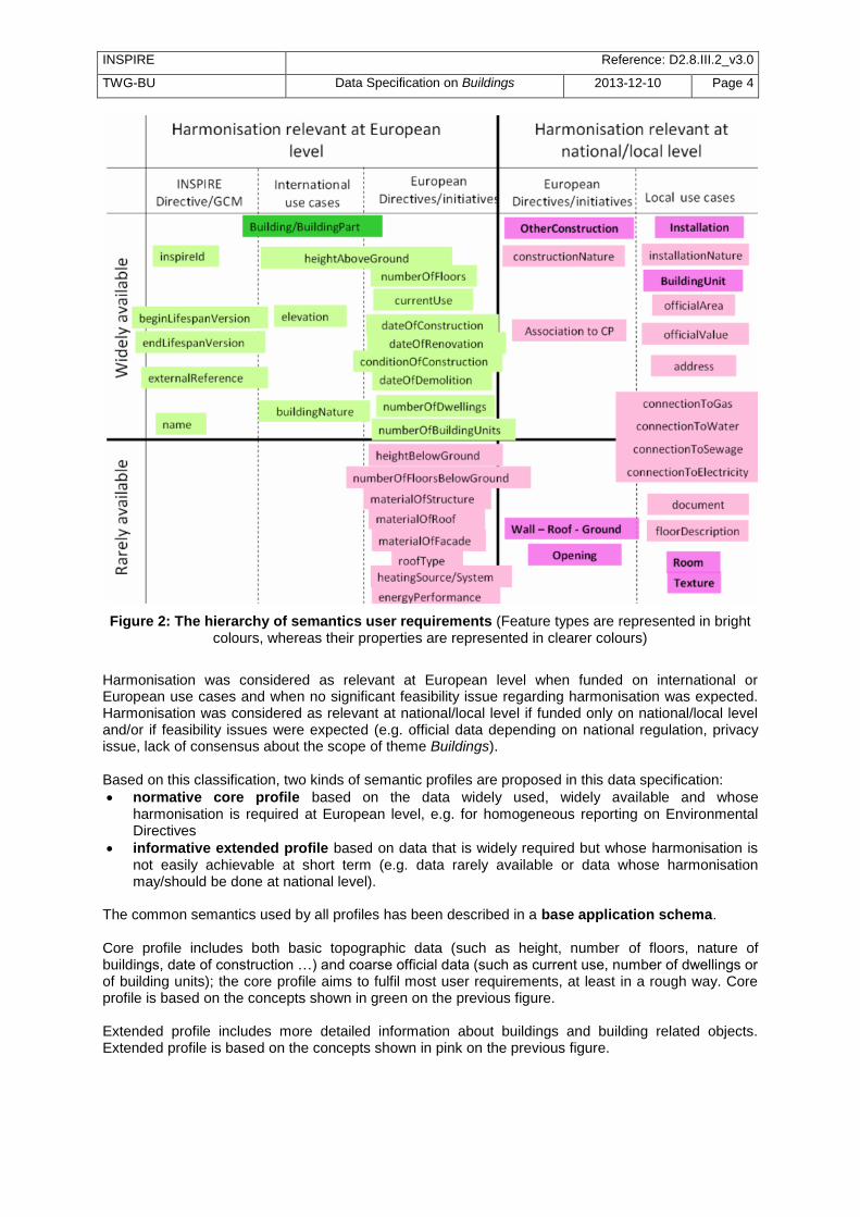
Figure 2: The hierarchy of semantics user requirements (Feature types are represented in bright colours, whereas their properties are represented in clearer colours)
Harmonisation was considered as relevant at European level when funded on international or European use cases and when no significant feasibility issue regarding harmonisation was expected. Harmonisation was considered as relevant at national/local level if funded only on national/local level and/or if feasibility issues were expected (e.g. official data depending on national regulation, privacy issue, lack of consensus about the scope of theme Buildings). Based on this classification, two kinds of semantic profiles are proposed in this data specification:
normative core profile based on the data widely used, widely available and whose harmonisation is required at European level, e.g. for homogeneous reporting on Environmental Directives
informative extended profile based on data that is widely required but whose harmonisation is not easily achievable at short term (e.g. data rarely available or data whose harmonisation may/should be done at national level).
The common semantics used by all profiles has been described in a base application schema. Core profile includes both basic topographic data (such as height, number of floors, nature of buildings, date of construction …) and coarse official data (such as current use, number of dwellings or of building units); the core profile aims to fulfil most user requirements, at least in a rough way. Core profile is based on the concepts shown in green on the previous figure. Extended profile includes more detailed information about buildings and building related objects. Extended profile is based on the concepts shown in pink on the previous figure.

INSPIRE Reference: D2.8.III.2_v3.0
TWG-BU Data Specification on Buildings 2013-12-10 Page 5
Extended profile may be applied as a whole but also aims to be a ―reservoir‖ of proposals for extensions of core INSPIRE profile, i.e. only a selection of proposed feature types and attributes may be added. More explanations about this topic are given in annex F. Moreover, some mechanisms (external reference, address and document) have been included to enable data producers to provide a link between the data considered as directly under the scope of theme Buildings and business data considered as out of scope of the theme (such as owner/tenant, building permit, detailed activity of the building).
2.2.2.1.2. Geometric aspects Building data may be available and required either as 2D (or 2,5D) data or as 3D data. This data specification is proposing two kinds of geometric profiles: - 2D profile (with 2D or 2,5D geometry) - 3D profile (with 3D geometry)
NOTE: term ―2D profile‖ is used for simplicity reason (in order to have a short title) but accommodates both 2D and 2,5D data. These 2D and 3D profiles are proposed to make life easier both to data producers and data users: - most data producers have only 2D or 2,5D data ; it will be easier for them to make their data
compliant with core 2D profile that deals only with 2D and 2,5D data - a core 3D profile has been developed, mainly to enable producers of 3D data to conform to
INSPIRE model without having to ―flatten‖ their data. - most GIS deals only with 2D or 2,5D data; users will be enabled to choose data compliant with
INSPIRE 2D or 3D profiles This core normative 3D profile is based on the simple semantic of core profile and allows all the levels of detail of CityGML.
2.2.2.1.3. Application schemas and profiles The data specification includes six application schemas. Two of them are just abstract application schemas gathering the concepts that are used in common by the other application schemas, i.e. the instanciable ones. The delivery of data may be done, using four options (called profiles) that consist of a combination of application schemas, as explained in the following table and figure.
Table 1: The profile approach for theme Buildings
Basic semantic Rich semantic
2D geometry Core 2D profile uses application schemas:
- base - Buildings2D
Extended 2D profile uses application schemas:
- base - Buildings2D
- base extended - extended 2D
3D geometry Core 3D profile uses application schemas:
- base - Buildings3D
Extended 3D profile uses application schemas:
- base - Buildings3D
- base extended - extended 3D
The profiles (Core 2D, Core 3D, Extended 2D, Extended 3D) are defined by the respective instanciable application schemas and may use the concepts defined in other application schemas, as explained in the previous table.

INSPIRE Reference: D2.8.III.2_v3.0
TWG-BU Data Specification on Buildings 2013-12-10 Page 6
Figure 3: Content and structure of application schemas for theme Buildings
Feature types are represented in blue. Abstract application schemas are represented in green. Instanciable application schemas are represented in red.
NOTE: Data producers may also extend INSPIRE profiles by other information not included in this specification, under the condition they respect the rules provided in the Generic Conceptual Model.
Figure 4: Modular approach for modelling Buildings theme

INSPIRE Reference: D2.8.III.2_v3.0
TWG-BU Data Specification on Buildings 2013-12-10 Page 7
2.2.2.2. Modular scope: There may be different kinds and sizes of buildings and constructions. In a similar way to the modular levels of information offered by the profile approach, this data specification defines three levels of priority for INSPIRE, regarding the scope of the theme:
Figure 5: Modular approach for scope of theme Buildings
The first priority, the data the most expected by INSPIRE includes: - The conventional buildings are considered as building by every one (fitting with all the various
definitions of buildings), generally hosting human activities (residential, industrial, commerce and services) and being of large or medium size (around 15-20 m2 and more); these conventional
buildings are required by most use cases, such as for assessment of population in an area of interest, census, spatial planning, modelling of physical phenomena. Typical examples are houses, block of flats, factories, supermarkets, …
- The specific (significant) buildings are the buildings of significant size or height with specific physical aspect that make them usable as landmarks and required by use cases such as mapping or travel safety. Typical examples are towers, stadium, churches, …
The second priority, the data that should be in INSPIRE includes: - The non-conventional buildings fit only partly with the definition(s) of building; for instance, they
are only partly constructed, such as caves or underground shelters, stations, car parks or they are permanent only by fact but not by nature such as mobile homes, huts, …If hosting human activities, these non-conventional buildings are required by use cases such as census, studies about precarious habitat, vulnerability to risk
- The ancillary buildings are buildings of small size (around 10 m2) that are used only in connection
with another larger building, such as the garages or garden shelters near houses. These ancillary buildings may influence the land use / land cover phenomena.
- Other constructions are the constructions required by the use cases considered by this data specification. Typical examples are city walls, bridges, chimneys, acoustic fences. The whole list may be found in the model (clause 5).
The last priority, the data that may be in INSPIRE includes all the other buildings and constructions, mainly the very small size ones (one or several m2), such as phone booth, bus shelters, statues, …
These buildings and constructions may be required at local level for asset management, protection of patrimony, …

INSPIRE Reference: D2.8.III.2_v3.0
TWG-BU Data Specification on Buildings 2013-12-10 Page 8
2.2.2.3. Links and overlaps with other themes
2.2.2.3.1. Overview
Theme Buildings has overlaps with themes dealing with facilities, as buildings may be part of governmental services, industrial, agricultural, transport or hydrographical facilities and with theme Geographical Names as buildings may have a toponym.
Some buildings and constructions are included in other INSPIRE themes, mainly in the facilities themes (for instance, a building may host a school, a prison, a city hall or be part of a farm or a factory). The general principle is that, for same entities, the theme Building focuses on a physical/topographic view whereas the facility themes focus on a functional view. Aggregated building data may be found as built-up areas in themes Land Cover or Land Use and as settlements in theme Geographical Names.
Moreover, theme Buildings is often used in conjunction with other INSPIRE themes by the use cases addressed by this data specification. For more details, see annex B.
Figure 6: Links and overlaps between Buildings and other INSPIRE themes
2.2.2.3.2. Classification of buildings This data specification proposes a simple classification of buildings, based on their current use. Users will find more detailed information in the themes dealing with facilities.
Table 2: The classification of buildings
Current use – high level Current use – detailed level
residential Provided by DS BU
agricultural Provided by DS AF
industrial Provided by DS PF
commerceAndServices - office
commerceAndServices - trade
commerceAndServices – public service Provided by DS US

INSPIRE Reference: D2.8.III.2_v3.0
TWG-BU Data Specification on Buildings 2013-12-10 Page 9
Open issue 1: The articulation between Buildings and facilities was poorly tested or not tested at all during the consultation phase. So, there is a real risk that data between these themes will not connect as expected. This will be a point to be carefully monitored by the maintenance process of INSPIRE specifications.
Definition: Geographical location of buildings [Directive 2007/2/EC]. Description: A building is a covered facility, usable for the protection of humans, animals, things or the production of economic goods. A building refers to any structure permanently constructed or erected on its site. Information on location of buildings may be supplied as points or with the actual basic form of the building. Usually buildings are part of cadastre. On the local level buildings are available within the large scale cadastral maps or cadastral data sets and are geometrically represented as surfaces. Most buildings can be identified (geocoded) by address (separate theme in INSPIRE).
Entry in the INSPIRE registry: http://inspire.ec.europa.eu/theme/bu/
2.3 Normative References [Directive 2007/2/EC] Directive 2007/2/EC of the European Parliament and of the Council of 14 March
2007 establishing an Infrastructure for Spatial Information in the European Community (INSPIRE)
[ISO 19107] EN ISO 19107:2005, Geographic Information – Spatial Schema [ISO 19108] EN ISO 19108:2005, Geographic Information – Temporal Schema [ISO 19108-c] ISO 19108:2002/Cor 1:2006, Geographic Information – Temporal Schema, Technical
Corrigendum 1 [ISO 19111] EN ISO 19111:2007 Geographic information - Spatial referencing by coordinates (ISO
19111:2007) [ISO 19113] EN ISO 19113:2005, Geographic Information – Quality principles [ISO 19115] EN ISO 19115:2005, Geographic information – Metadata (ISO 19115:2003) [ISO 19118] EN ISO 19118:2006, Geographic information – Encoding (ISO 19118:2005) [ISO 19125-1] EN ISO 19125-1:2004, Geographic Information – Simple feature access – Part 1:
Common architecture [ISO 19135] EN ISO 19135:2007 Geographic information – Procedures for item registration (ISO
19135:2005) [ISO 19138] ISO/TS 19138:2006, Geographic Information – Data quality measures [ISO 19139] ISO/TS 19139:2007, Geographic information – Metadata – XML schema
implementation [ISO 19157] ISO/DIS 19157, Geographic information – Data quality [OGC 06-103r4] Implementation Specification for Geographic Information - Simple feature access –
Part 1: Common Architecture v1.2.1

INSPIRE Reference: D2.8.III.2_v3.0
TWG-BU Data Specification on Buildings 2013-12-10 Page 10
NOTE This is an updated version of "EN ISO 19125-1:2004, Geographic information – Simple feature access – Part 1: Common architecture".
[Regulation 1205/2008/EC] Regulation 1205/2008/EC implementing Directive 2007/2/EC of the
European Parliament and of the Council as regards metadata [Regulation 976/2009/EC] Commission Regulation (EC) No 976/2009 of 19 October 2009
implementing Directive 2007/2/EC of the European Parliament and of the Council as regards the Network Services
[Regulation 1089/2010/EC] Commission Regulation (EU) No 1089/2010 of 23 November 2010
implementing Directive 2007/2/EC of the European Parliament and of the Council as regards interoperability of spatial data sets and services
2.4 Terms and definitions General terms and definitions helpful for understanding the INSPIRE data specification documents are defined in the INSPIRE Glossary
13.
Specifically, for the theme Buildings, the following terms are defined: 1. 2D data Geometry of features is represented in a two-dimensional space NOTE: In other words, the geometry of 2D data is given using (X,Y) coordinates. EXAMPLE:
Figure 7: A building represented by 2D data
2. 2.5D data Geometry of features is represented in a three-dimensional space with the constraint that, for each (X,Y) position, there is only one Z.
13
The INSPIRE Glossary is available from http://inspire-registry.jrc.ec.europa.eu/registers/GLOSSARY

INSPIRE Reference: D2.8.III.2_v3.0
TWG-BU Data Specification on Buildings 2013-12-10 Page 11
EXAMPLE:
Figure 8: A building represented by 2,5D data
3. 3D data Geometry of features is represented in a three-dimensional space. NOTE: In other words, the geometry of 2D data is given using (X,Y,Z) coordinates without any constraints. EXAMPLE:
Figure 9: A building represented by 3D data
4. Building component Any sub-division or elements of a building. EXAMPLES: wall, roof, room

INSPIRE Reference: D2.8.III.2_v3.0
TWG-BU Data Specification on Buildings 2013-12-10 Page 12
2.5 Symbols and abbreviations
AC Atmospheric Conditions
AD Address
AF Agricultural and Aquacultural Facilities
ATS Abstract Test Suite
AU Administrative Units
BU Buildings
CP Cadastral Parcels
CRS Coordinate Reference System
DS DT Data Specification Drafting Team
DTM Digital Terrain Model
EC European Commission
EEA European Environmental Agency
EL Elevation
ENC Electronic Navigation Charts
EPBD Energy Performance of Buildings Directive
ETRS89 European Terrestrial Reference System 1989
ETRS89-LAEA Lambert Azimuthal Equal Area
EVRS European Vertical Reference System
FE Filter Encoding
GCM General Conceptual Model
GML Geographic Markup Language
GN Geographical Names
GRS80 Geodetic Reference System 1980
HY Hydrography
ICAO International Civil Aviation Organization
IR Implementing Rule
ISDSS Interoperability of Spatial Data Sets and Services
ISO International Organization for Standardization
ITRS International Terrestrial Reference System
JRC Joint Research Centre
LADM Land Administration Domain Model
LAT Lowest Astronomical Tide
LC Land Cover
LMO Legally Mandated Organization
LoD Level Of Detail

INSPIRE Reference: D2.8.III.2_v3.0
TWG-BU Data Specification on Buildings 2013-12-10 Page 13
LU Land Use
MF Meteorological geographical Features
MS Member State
NMCA National Mapping and Cadastral Agency
NZ Natural Risk Zones
OGC Open Geospatial Consortium
OI Orthoimagery
PD Population Distribution
PF Production and Industrial Facilities
RGB Red Green Blue
SDIC Spatial Data Interest Community
SE Style Encoding
SU Statistical Units
TG Technical Guidance
TN Transport Networks
TWG Thematic Working Group
UML Unified Modeling Language
URI Uniform Resource Identifier
US Utility and Governmental Services
UTC Coordinated Universal Time
UTF Unicode Transformation Format
WFS Web Feature Service
WMS Web Map Service
XML EXtensible Markup Language

INSPIRE Reference: D2.8.III.2_v3.0
TWG-BU Data Specification on Buildings 2013-12-10 Page 14
2.6 How the Technical Guidelines map to the Implementing Rules The schematic diagram in Figure 10 gives an overview of the relationships between the INSPIRE legal acts (the INSPIRE Directive and Implementing Rules) and the INSPIRE Technical Guidelines. The INSPIRE Directive and Implementing Rules include legally binding requirements that describe, usually on an abstract level, what Member States must implement. In contrast, the Technical Guidelines define how Member States might implement the requirements included in the INSPIRE Implementing Rules. As such, they may include non-binding technical requirements that must be satisfied if a Member State data provider chooses to conform to the Technical Guidelines. Implementing these Technical Guidelines will maximise the interoperability of INSPIRE spatial data sets.
Figure 10 - Relationship between INSPIRE Implementing Rules and Technical Guidelines
2.6.1 Requirements The purpose of these Technical Guidelines (Data specifications on Buildings) is to provide practical guidance for implementation that is guided by, and satisfies, the (legally binding) requirements included for the spatial data theme Buildings in the Regulation (Implementing Rules) on interoperability of spatial data sets and services. These requirements are highlighted in this document as follows:
IR Requirement Article / Annex / Section no.
Title / Heading This style is used for requirements contained in the Implementing Rules on interoperability of spatial
data sets and services (Commission Regulation (EU) No 1089/2010).

INSPIRE Reference: D2.8.III.2_v3.0
TWG-BU Data Specification on Buildings 2013-12-10 Page 15
For each of these IR requirements, these Technical Guidelines contain additional explanations and examples. NOTE The Abstract Test Suite (ATS) in Annex A contains conformance tests that directly check conformance with these IR requirements. Furthermore, these Technical Guidelines may propose a specific technical implementation for satisfying an IR requirement. In such cases, these Technical Guidelines may contain additional technical requirements that need to be met in order to be conformant with the corresponding IR requirement when using this proposed implementation. These technical requirements are highlighted as follows:
TG Requirement X This style is used for requirements for a specific technical solution proposed in
these Technical Guidelines for an IR requirement.
NOTE 1 Conformance of a data set with the TG requirement(s) included in the ATS implies conformance with the corresponding IR requirement(s). NOTE 2 In addition to the requirements included in the Implementing Rules on interoperability of spatial data sets and services, the INSPIRE Directive includes further legally binding obligations that put additional requirements on data providers. For example, Art. 10(2) requires that Member States shall, where appropriate, decide by mutual consent on the depiction and position of geographical features whose location spans the frontier between two or more Member States. General guidance for how to meet these obligations is provided in the INSPIRE framework documents.
2.6.2 Recommendations In addition to IR and TG requirements, these Technical Guidelines may also include a number of recommendations for facilitating implementation or for further and coherent development of an interoperable infrastructure.
Recommendation X Recommendations are shown using this style.
NOTE The implementation of recommendations is not mandatory. Compliance with these Technical Guidelines or the legal obligation does not depend on the fulfilment of the recommendations.
2.6.3 Conformance Annex A includes the abstract test suite for checking conformance with the requirements included in these Technical Guidelines and the corresponding parts of the Implementing Rules (Commission Regulation (EU) No 1089/2010).
3 Specification scopes This data specification does not distinguish different specification scopes, but just considers one general scope. NOTE For more information on specification scopes, see [ISO 19131:2007], clause 8 and Annex D.

INSPIRE Reference: D2.8.III.2_v3.0
TWG-BU Data Specification on Buildings 2013-12-10 Page 16
4 Identification information These Technical Guidelines are identified by the following URI: http://inspire.ec.europa.eu/tg/BU/3.0 NOTE ISO 19131 suggests further identification information to be included in this section, e.g. the title, abstract or spatial representation type. The proposed items are already described in the document metadata, executive summary, overview description (section 2) and descriptions of the application schemas (section 5). In order to avoid redundancy, they are not repeated here.

INSPIRE Reference: D2.8.III.2_v3.0
TWG-BU Data Specification on Buildings 2013-12-10 Page 17
5 Data content and structure
5.1 Application schemas – Overview
5.1.1 Application schemas included in the IRs Articles 3, 4 and 5 of the Implementing Rules lay down the requirements for the content and structure of the data sets related to the INSPIRE Annex themes.
IR Requirement Article 4
Types for the Exchange and Classification of Spatial Objects
1. For the exchange and classification of spatial objects from data sets meeting the conditions laid down in Article 4 of Directive 2007/2/EC, Member States shall use the spatial object types and associated data types, enumerations and code lists that are defined in Annexes II, III and IV for the themes the data sets relate to. 2. Spatial object types and data types shall comply with the definitions and constraints and include the attributes and association roles set out in the Annexes. 3. The enumerations and code lists used in attributes or association roles of spatial object types or data
types shall comply with the definitions and include the values set out in Annex II. The enumeration and code list values are uniquely identified by language-neutral mnemonic codes for computers. The values may also include a language-specific name to be used for human interaction.
The types to be used for the exchange and classification of spatial objects from data sets related to the spatial data theme Buildings are defined in the following application schemas (see following sections):
BuildingsBase application schema describes the concepts that are common to all other Buildings application schemas; it contains mainly the core normative semantics of theme Buildings
Buildings2D application schema describes the 2D geometric representation of the spatial object types defined in Buildings Base application schema, namely buildings and building parts; it inherits from the common semantics of Buildings base
Buildings3D application schema describes the 3D geometric representation of the spatial object types defined in Buildings Base application schema, namely buildings and building parts; it inherits from the common semantics of Buildings base
The application schemas specify requirements on the properties of each spatial object including its multiplicity, domain of valid values, constraints, etc. NOTE The application schemas presented in this section contain some additional information that is not included in the Implementing Rules, in particular multiplicities of attributes and association roles.
TG Requirement 1 Spatial object types and data types shall comply with the multiplicities defined for the attributes and association roles in this section.

INSPIRE Reference: D2.8.III.2_v3.0
TWG-BU Data Specification on Buildings 2013-12-10 Page 18
An application schema may include references (e.g. in attributes or inheritance relationships) to common types or types defined in other spatial data themes. These types can be found in a sub-section called ―Imported Types‖ at the end of each application schema section. The common types referred to from application schemas included in the IRs are addressed in Article 3.
IR Requirement Article 3
Common Types
Types that are common to several of the themes listed in Annexes I, II and III to Directive 2007/2/EC shall conform to the definitions and constraints and include the attributes and
association roles set out in Annex I.
NOTE Since the IRs contain the types for all INSPIRE spatial data themes in one document, Article 3 does not explicitly refer to types defined in other spatial data themes, but only to types defined in external data models. Common types are described in detail in the Generic Conceptual Model [DS-D2.7], in the relevant international standards (e.g. of the ISO 19100 series) or in the documents on the common INSPIRE models [DS-D2.10.x]. For detailed descriptions of types defined in other spatial data themes, see the corresponding Data Specification TG document [DS-D2.8.x].
5.1.2 Additional recommended application schemas In addition to the application schemas listed above, the following additional application schemas have been defined for the theme Buildings (see following sections): - BuildingsExtendedBase application schema describes the additional semantics that should be used to extend normative profiles, whatever the chosen geometric representation (2D or 3D) is. - BuildingsExtended2D application schema describes the 2D geometric representation of the additional spatial object types (namely installations, other constructions, building units); it inherits both from the common semantics of <Buildings ExtendedBase> and of the 2D geometric representation of buildings and building parts. - BuildingsExtended3D application schema describes both the 3D geometric representation of the additional spatial object types (namely installations, other constructions, building units) and the additional concepts that should be used to provide more detailed information about buildings and associated objects, when represented by 3D data (walls, roofs, openings, room, textures, …) ; it inherits both from the common semantics of <Buildings ExtendedBase> and of the 3D geometric representation of buildings and building parts. These additional application schemas are not included in the IRs. They typically address requirements from specific (groups of) use cases and/or may be used to provide additional information. They are included in this specification in order to improve interoperability also for these additional aspects and to illustrate the extensibility of the application schemas included in the IRs.

INSPIRE Reference: D2.8.III.2_v3.0
TWG-BU Data Specification on Buildings 2013-12-10 Page 19
Recommendation 1 Additional and/or use case-specific information related to the theme Buildings should be made available using the spatial object types and data types specified in the following application schema(s): BuildingsExtendedBase, BuildingsExtended2D, BuildingsExtended3D.
These spatial object types and data types should comply with the
definitions and constraints and include the attributes and association roles defined in this section.
The enumerations and code lists used in attributes or association roles of
spatial object types or data types should comply with the definitions and include the values defined in this section.
5.2 Basic notions This section explains some of the basic notions used in the INSPIRE application schemas. These explanations are based on the GCM [DS-D2.5].
5.2.1 Notation
5.2.1.1. Unified Modeling Language (UML) The application schemas included in this section are specified in UML, version 2.1. The spatial object types, their properties and associated types are shown in UML class diagrams. NOTE For an overview of the UML notation, see Annex D in [ISO 19103].
Figure 11: Dependencies between application schemas of theme Buildings

INSPIRE Reference: D2.8.III.2_v3.0
TWG-BU Data Specification on Buildings 2013-12-10 Page 20
The use of a common conceptual schema language (i.e. UML) allows for an automated processing of application schemas and the encoding, querying and updating of data based on the application schema – across different themes and different levels of detail. The following important rules related to class inheritance and abstract classes are included in the IRs.
IR Requirement Article 5 Types
(…) 2. Types that are a sub-type of another type shall also include all this type‘s attributes and
association roles.
3. Abstract types shall not be instantiated.
The use of UML conforms to ISO 19109 8.3 and ISO/TS 19103 with the exception that UML 2.1 instead of ISO/IEC 19501 is being used. The use of UML also conforms to ISO 19136 E.2.1.1.1-E.2.1.1.4. NOTE ISO/TS 19103 and ISO 19109 specify a profile of UML to be used in conjunction with the ISO 19100 series. This includes in particular a list of stereotypes and basic types to be used in application schemas. ISO 19136 specifies a more restricted UML profile that allows for a direct encoding in XML Schema for data transfer purposes. To model constraints on the spatial object types and their properties, in particular to express data/data set consistency rules, OCL (Object Constraint Language) is used as described in ISO/TS 19103, whenever possible. In addition, all constraints are described in the feature catalogue in English, too. NOTE Since ―void‖ is not a concept supported by OCL, OCL constraints cannot include expressions to test whether a value is a void value. Such constraints may only be expressed in natural language.
5.2.1.2. Stereotypes In the application schemas in this section several stereotypes are used that have been defined as part of a UML profile for use in INSPIRE [DS-D2.5]. These are explained in Table 3 below.
Table 3 – Stereotypes (adapted from [DS-D2.5])
Stereotype Model element
Description
applicationSchema Package An INSPIRE application schema according to ISO 19109 and the Generic Conceptual Model.
leaf Package
A package that is not an application schema and contains no packages.
featureType Class A spatial object type.
type Class A type that is not directly instantiable, but is used as an abstract collection of operation, attribute and relation signatures. This stereotype should usually not be used in INSPIRE application schemas as these are on a different conceptual level than classifiers with this stereotype.
dataType Class A structured data type without identity.
union Class A structured data type without identity where exactly one of the properties of the type is present in any instance.
enumeration Class An enumeration.
codeList Class A code list.

INSPIRE Reference: D2.8.III.2_v3.0
TWG-BU Data Specification on Buildings 2013-12-10 Page 21
import Dependency The model elements of the supplier package are imported.
voidable Attribute, association role
A voidable attribute or association role (see section 5.2.2).
lifeCycleInfo Attribute, association role
If in an application schema a property is considered to be part of the life-cycle information of a spatial object type, the property shall receive this stereotype.
version Association role
If in an application schema an association role ends at a spatial object type, this stereotype denotes that the value of the property is meant to be a specific version of the spatial object, not the spatial object in general.
5.2.2 Voidable characteristics
The «voidable» stereotype is used to characterise those properties of a spatial object that may not be present in some spatial data sets, even though they may be present or applicable in the real world. This does not mean that it is optional to provide a value for those properties. For all properties defined for a spatial object, a value has to be provided – either the corresponding value (if available in the data set maintained by the data provider) or the value of void. A void value shall imply that no corresponding value is contained in the source spatial data set maintained by the data provider or no corresponding value can be derived from existing values at reasonable costs.
Recommendation 2 The reason for a void value should be provided where possible using a listed value from the VoidReasonValue code list to indicate the reason for the missing value.
The VoidReasonValue type is a code list, which includes the following pre-defined values:
Unpopulated: The property is not part of the dataset maintained by the data provider. However, the characteristic may exist in the real world. For example when the ―elevation of the water body above the sea level‖ has not been included in a dataset containing lake spatial objects, then the reason for a void value of this property would be ‗Unpopulated‘. The property receives this value for all spatial objects in the spatial data set.
Unknown: The correct value for the specific spatial object is not known to, and not computable by the data provider. However, a correct value may exist. For example when the ―elevation of the water body above the sea level‖ of a certain lake has not been measured, then the reason for a void value of this property would be ‗Unknown‘. This value is applied only to those spatial objects where the property in question is not known.
Withheld: The characteristic may exist, but is confidential and not divulged by the data provider. NOTE It is possible that additional reasons will be identified in the future, in particular to support reasons / special values in coverage ranges. The «voidable» stereotype does not give any information on whether or not a characteristic exists in the real world. This is expressed using the multiplicity:
If a characteristic may or may not exist in the real world, its minimum cardinality shall be defined as 0. For example, if an Address may or may not have a house number, the multiplicity of the corresponding property shall be 0..1.
If at least one value for a certain characteristic exists in the real world, the minimum cardinality shall be defined as 1. For example, if an Administrative Unit always has at least one name, the multiplicity of the corresponding property shall be 1..*.
In both cases, the «voidable» stereotype can be applied. In cases where the minimum multiplicity is 0, the absence of a value indicates that it is known that no value exists, whereas a value of void indicates that it is not known whether a value exists or not.

INSPIRE Reference: D2.8.III.2_v3.0
TWG-BU Data Specification on Buildings 2013-12-10 Page 22
EXAMPLE If an address does not have a house number, the corresponding Address object should not have any value for the «voidable» attribute house number. If the house number is simply not known or not populated in the data set, the Address object should receive a value of void (with the corresponding void reason) for the house number attribute.
5.2.3 Enumerations Enumerations are modelled as classes in the application schemas. Their values are modelled as attributes of the enumeration class using the following modelling style:
No initial value, but only the attribute name part, is used.
The attribute name conforms to the rules for attributes names, i.e. is a lowerCamelCase name. Exceptions are words that consist of all uppercase letters (acronyms).
IR Requirement Article 6
Code Lists and Enumerations
(…) 5) Attributes or association roles of spatial object types or data types that have an enumeration
type may only take values from the lists specified for the enumeration type.‖
5.2.4 Code lists Code lists are modelled as classes in the application schemas. Their values, however, are managed outside of the application schema.
5.2.4.1. Code list types The IRs distinguish the following types of code lists.
IR Requirement Article 6
Code Lists and Enumerations
1) Code lists shall be of one of the following types, as specified in the Annexes: a) code lists whose allowed values comprise only the values specified in this Regulation; b) code lists whose allowed values comprise the values specified in this Regulation and
narrower values defined by data providers; c) code lists whose allowed values comprise the values specified in this Regulation and
additional values at any level defined by data providers; d) code lists, whose allowed values comprise any values defined by data providers. For the purposes of points (b), (c) and (d), in addition to the allowed values, data providers may
use the values specified in the relevant INSPIRE Technical Guidance document available on the
INSPIRE web site of the Joint Research Centre.
The type of code list is represented in the UML model through the tagged value extensibility, which can take the following values:
none, representing code lists whose allowed values comprise only the values specified in the IRs (type a);
narrower, representing code lists whose allowed values comprise the values specified in the IRs and narrower values defined by data providers (type b);

INSPIRE Reference: D2.8.III.2_v3.0
TWG-BU Data Specification on Buildings 2013-12-10 Page 23
open, representing code lists whose allowed values comprise the values specified in the IRs and additional values at any level defined by data providers (type c); and
any, representing code lists, for which the IRs do not specify any allowed values, i.e. whose allowed values comprise any values defined by data providers (type d).
Recommendation 3 Additional values defined by data providers should not replace or redefine any value already specified in the IRs.
NOTE This data specification may specify recommended values for some of the code lists of type (b), (c) and (d) (see section 5.2.4.3). These recommended values are specified in a dedicated Annex. In addition, code lists can be hierarchical, as explained in Article 6(2) of the IRs.
IR Requirement Article 6
Code Lists and Enumerations (…) 2) Code lists may be hierarchical. Values of hierarchical code lists may have a more generic parent
value. Where the valid values of a hierarchical code list are specified in a table in this
Regulation, the parent values are listed in the last column.
The type of code list and whether it is hierarchical or not is also indicated in the feature catalogues.
5.2.4.2. Obligations on data providers
IR Requirement Article 6
Code Lists and Enumerations
(….) 3) Where, for an attribute whose type is a code list as referred to in points (b), (c) or (d) of
paragraph 1, a data provider provides a value that is not specified in this Regulation, that value and its definition shall be made available in a register.
4) Attributes or association roles of spatial object types or data types whose type is a code list may
only take values that are allowed according to the specification of the code list.
Article 6(4) obliges data providers to use only values that are allowed according to the specification of the code list. The ―allowed values according to the specification of the code list‖ are the values explicitly defined in the IRs plus (in the case of code lists of type (b), (c) and (d)) additional values defined by data providers. For attributes whose type is a code list of type (b), (c) or (d) data providers may use additional values that are not defined in the IRs. Article 6(3) requires that such additional values and their definition be made available in a register. This enables users of the data to look up the meaning of the additional values used in a data set, and also facilitates the re-use of additional values by other data providers (potentially across Member States). NOTE Guidelines for setting up registers for additional values and how to register additional values in these registers is still an open discussion point between Member States and the Commission.

INSPIRE Reference: D2.8.III.2_v3.0
TWG-BU Data Specification on Buildings 2013-12-10 Page 24
5.2.4.3. Recommended code list values For code lists of type (b), (c) and (d), this data specification may propose additional values as a recommendation (in a dedicated Annex). These values will be included in the INSPIRE code list register. This will facilitate and encourage the usage of the recommended values by data providers since the obligation to make additional values defined by data providers available in a register (see section 5.2.4.2) is already met.
Recommendation 4 Where these Technical Guidelines recommend values for a code list in addition to those specified in the IRs, these values should be used.
NOTE For some code lists of type (d), no values may be specified in these Technical Guidelines. In these cases, any additional value defined by data providers may be used.
5.2.4.4. Governance The following two types of code lists are distinguished in INSPIRE:
Code lists that are governed by INSPIRE (INSPIRE-governed code lists). These code lists will be managed centrally in the INSPIRE code list register. Change requests to these code lists (e.g. to add, deprecate or supersede values) are processed and decided upon using the INSPIRE code list register‘s maintenance workflows.
INSPIRE-governed code lists will be made available in the INSPIRE code list register at http://inspire.ec.europa.eu/codelist/<CodeListName>. They will be available in SKOS/RDF, XML and HTML. The maintenance will follow the procedures defined in ISO 19135. This means that the only allowed changes to a code list are the addition, deprecation or supersession of values, i.e. no value will ever be deleted, but only receive different statuses (valid, deprecated, superseded). Identifiers for values of INSPIRE-governed code lists are constructed using the pattern http://inspire.ec.europa.eu/codelist/<CodeListName>/<value>.
Code lists that are governed by an organisation outside of INSPIRE (externally governed code lists). These code lists are managed by an organisation outside of INSPIRE, e.g. the World Meteorological Organization (WMO) or the World Health Organization (WHO). Change requests to these code lists follow the maintenance workflows defined by the maintaining organisations. Note that in some cases, no such workflows may be formally defined. Since the updates of externally governed code lists is outside the control of INSPIRE, the IRs and these Technical Guidelines reference a specific version for such code lists. The tables describing externally governed code lists in this section contain the following columns:
The Governance column describes the external organisation that is responsible for maintaining the code list.
The Source column specifies a citation for the authoritative source for the values of the code list. For code lists, whose values are mandated in the IRs, this citation should include the version of the code list used in INSPIRE. The version can be specified using a version number or the publication date. For code list values recommended in these Technical Guidelines, the citation may refer to the ―latest available version‖.
In some cases, for INSPIRE only a subset of an externally governed code list is relevant. The subset is specified using the Subset column.
The Availability column specifies from where (e.g. URL) the values of the externally governed code list are available, and in which formats. Formats can include machine-readable (e.g. SKOS/RDF, XML) or human-readable (e.g. HTML, PDF) ones.
Code list values are encoded using http URIs and labels. Rules for generating these URIs and labels are specified in a separate table.

INSPIRE Reference: D2.8.III.2_v3.0
TWG-BU Data Specification on Buildings 2013-12-10 Page 25
Recommendation 5 The http URIs and labels used for encoding code list values should be taken from the INSPIRE code list registry for INSPIRE-governed code lists and generated according to the relevant rules specified for externally governed code lists.
NOTE Where practicable, the INSPIRE code list register could also provide http URIs and labels for externally governed code lists.
5.2.4.5. Vocabulary For each code list, a tagged value called ―vocabulary‖ is specified to define a URI identifying the values of the code list. For INSPIRE-governed code lists and externally governed code lists that do not have a persistent identifier, the URI is constructed following the pattern http://inspire.ec.europa.eu/codelist/<UpperCamelCaseName>. If the value is missing or empty, this indicates an empty code list. If no sub-classes are defined for this empty code list, this means that any code list may be used that meets the given definition. An empty code list may also be used as a super-class for a number of specific code lists whose values may be used to specify the attribute value. If the sub-classes specified in the model represent all valid extensions to the empty code list, the subtyping relationship is qualified with the standard UML constraint "{complete,disjoint}".
5.2.5 Identifier management
IR Requirement Article 9
Identifier Management 1. The data type Identifier defined in Section 2.1 of Annex I shall be used as a type for the external
object identifier of a spatial object. 2. The external object identifier for the unique identification of spatial objects shall not be changed
during the life-cycle of a spatial object.
NOTE 1 An external object identifier is a unique object identifier which is published by the responsible body, which may be used by external applications to reference the spatial object. [DS-D2.5] NOTE 2 Article 9(1) is implemented in each application schema by including the attribute inspireId of type Identifier. NOTE 3 Article 9(2) is ensured if the namespace and localId attributes of the Identifier remains the same for different versions of a spatial object; the version attribute can of course change.
5.2.6 Geometry representation
IR Requirement Article 12
Other Requirements & Rules 1. The value domain of spatial properties defined in this Regulation shall be restricted to the
Simple Feature spatial schema as defined in Herring, John R. (ed.), OpenGIS® Implementation

INSPIRE Reference: D2.8.III.2_v3.0
TWG-BU Data Specification on Buildings 2013-12-10 Page 26
Standard for Geographic information – Simple feature access – Part 1: Common architecture, version 1.2.1, Open Geospatial Consortium, 2011, unless specified otherwise for a specific
spatial data theme or type.
NOTE 1 The specification restricts the spatial schema to 0-, 1-, 2-, and 2.5-dimensional geometries where all curve interpolations are linear and surface interpolations are performed by triangles. NOTE 2 The topological relations of two spatial objects based on their specific geometry and topology properties can in principle be investigated by invoking the operations of the types defined in ISO 19107 (or the methods specified in EN ISO 19125-1).
5.2.7 Temporality representation The application schema(s) use(s) the derived attributes "beginLifespanVersion" and "endLifespanVersion" to record the lifespan of a spatial object. The attributes "beginLifespanVersion" specifies the date and time at which this version of the spatial object was inserted or changed in the spatial data set. The attribute "endLifespanVersion" specifies the date and time at which this version of the spatial object was superseded or retired in the spatial data set. NOTE 1 The attributes specify the beginning of the lifespan of the version in the spatial data set itself, which is different from the temporal characteristics of the real-world phenomenon described by the spatial object. This lifespan information, if available, supports mainly two requirements: First, knowledge about the spatial data set content at a specific time; second, knowledge about changes to a data set in a specific time frame. The lifespan information should be as detailed as in the data set (i.e., if the lifespan information in the data set includes seconds, the seconds should be represented in data published in INSPIRE) and include time zone information. NOTE 2 Changes to the attribute "endLifespanVersion" does not trigger a change in the attribute "beginLifespanVersion".
IR Requirement Article 10
Life-cycle of Spatial Objects (…) 3. Where the attributes beginLifespanVersion and endLifespanVersion are used, the value of
endLifespanVersion shall not be before the value of beginLifespanVersion.
NOTE The requirement expressed in the IR Requirement above will be included as constraints in the UML data models of all themes.
Recommendation 6 If life-cycle information is not maintained as part of the spatial data set, all spatial objects belonging to this data set should provide a void value with a reason of "unpopulated".

INSPIRE Reference: D2.8.III.2_v3.0
TWG-BU Data Specification on Buildings 2013-12-10 Page 27
5.3 Application schema BuildingsBase
5.3.1 Description
5.3.1.1. Narrative description Buildings Base application schema is an abstract application schema that describes the feature types, data types and code lists that are common to all the four instanciable application schemas, namely 2D, 3D, extended2D and extended3D. It addresses mainly the basic normative semantics and includes in addition a data type about the 2D geometric representation of buildings that is used by all the four instanciable application schemas.
5.3.1.1.1. Feature types
class Buildings - Base: Main Types
«featureType»
Building«featureType»
BuildingPart
+parts
«voidable»
0..*
Figure 12: Instanciable feature types
Buildings are enclosed constructions above and/or underground which are intended or used for the shelter of humans, animals, things or the production of economic goods and that refer to any structure permanently constructed or erected on its site. According to a CityGML concept, a complex building may be considered as an aggregation of BuildingParts, as shown on the following illustration:
From City GML
A BuildingPart is a sub-division of a Building that might have been considered as a building and that is homogeneous related to its physical, functional or temporal aspects. It is up to each data producer to define what is considered as a Building and what is considered as a BuildingPart (if this concept is used). This information has to be provided as metadata. More explanations and examples about how the concept of BuildingPart may and should be used are provided in clause 10 about Data capture.
One Building with 2 BuildingParts

INSPIRE Reference: D2.8.III.2_v3.0
TWG-BU Data Specification on Buildings 2013-12-10 Page 28
class Buildings - Base: Main Types
«featureType»
AbstractBuilding
«voidable»
+ buildingNature: BuildingNatureValue [0..*]
+ currentUse: CurrentUse [0..*]
+ numberOfDwellings: Integer [0..1]
+ numberOfBuildingUnits: Integer [0..1]
+ numberOfFloorsAboveGround: Integer [0..1]
«featureType»
AbstractConstruction
+ inspireId: Identifier
«voidable, l ifeCycleInfo»
+ beginLifespanVersion: DateTime
+ endLifespanVersion: DateTime [0..1]
«voidable»
+ conditionOfConstruction: ConditionOfConstructionValue
+ dateOfConstruction: DateOfEvent [0..1]
+ dateOfDemolition: DateOfEvent [0..1]
+ dateOfRenovation: DateOfEvent [0..1]
+ elevation: Elevation [0..*]
+ externalReference: ExternalReference [0..*]
+ heightAboveGround: HeightAboveGround [0..*]
+ name: GeographicalName [0..*]
«featureType»
Building«featureType»
BuildingPart
+parts
«voidable»
0..*
Figure 13: Feature types of Buildings Base application schema
Base application schema includes 2 abstract feature types: AbstractConstruction and AbstractBuilding:
o AbstractBuilding is an abstract feature type grouping the common properties of instanciable feature types Building and BuildingPart
o AbstractConstruction is an abstract feature type grouping the semantic properties of buildings, building parts and of some optional feature types that may be added to core profiles, in order to provide more information about theme Buildings. The optional feature types are described in extended application schemas.
Instanciable feature types Building and BuildingPart inherit both of the properties of abstract feature types AbstractConstruction and AbstractBuilding.

INSPIRE Reference: D2.8.III.2_v3.0
TWG-BU Data Specification on Buildings 2013-12-10 Page 29
5.3.1.1.2. Elevation
class Buildings - Base: Data Types
«dataType»
Elevation
+ elevationReference: ElevationReferenceValue
+ elevationValue: DirectPosition
class Buildings - Base: Code Lists
«codeList»
Elev ationReferenceValue
tags
extensibil ity = none
obligation = implementingRule
vocabulary = http://inspire.ec.europa.eu/codeList/ElevationReferenceValue
above ground envelope, bottom of construction, entrance
point, general eave, general ground, general roof, general
roof edge, highest eave, highest ground point, highest point,
highest roof edge, lowest eave, lowest floor above ground,
lowest ground point, lowest roof edge, top of construction.
Figure 14: The Elevation data type
A building or a construction may have several values of attribute elevation:
- the elevation may be measured at different levels of the building; this must be documented with attribute elevationReference, using the possible values given in the code list ElevationReferenceValue (see Figure 15: Examples of elevation references for different kinds of building) - the elevation may be given in various vertical reference systems; this has to be documented through the DirectPosition that contains both the elevation value itself and the Coordinate Reference System to which this value refers.
EXAMPLE (DirectPosition):
<pos srsName="urn:x-ogc:def:crs:EPSG:7.9.5. 5621" srsDimension="1">114</pos> The Spatial Reference System Name (srsName) is given by: - EPSG :7.9.5 : namespace (or register) and its version - 5621 : identifier of the CRS in the given register (here it is EVRF 2007) The srsDimension is 1 because related only to one dimension (elevation). The value of elevation is 114.
Recommendation 7 For territories that are in the scope of EVRS, the use EVRS as elevation datum is recommended.
However, some communities as marine or air navigation may have other requirements, coming from international standards.

INSPIRE Reference: D2.8.III.2_v3.0
TWG-BU Data Specification on Buildings 2013-12-10 Page 30
Figure 15: Examples of elevation references for different kinds of building
5.3.1.1.3. Attribute HeightAboveGround A construction of a building may have several values for the attribute HeightAboveGround, according to the levels that were chosen to compute it. The heightAboveGround of a construction or building is generally computed as the difference between an elevation measured at a high reference and the elevation measured at a low reference.
class Buildings - Base: Data Types
«dataType»
HeightAbov eGround
+ value: Length
«voidable»
+ heightReference: ElevationReferenceValue
+ lowReference: ElevationReferenceValue
+ status: HeightStatusValue
constraints
{valueUoMIsMetre}
class Buildings - Base: Code Lists
«codeList»
Elev ationReferenceValue
tags
extensibil ity = none
obligation = implementingRule
vocabulary = http://inspire.ec.europa.eu/codeList/ElevationReferenceValue
above ground envelope, bottom of construction, entrance
point, general eave, general ground, general roof, general
roof edge, highest eave, highest ground point, highest point,
highest roof edge, lowest eave, lowest floor above ground,
lowest ground point, lowest roof edge, top of construction.
class Buildings - Base: Code Lists
«codeList»
HeightStatusValue
tags
extensibil ity = none
obligation = implementingRule
vocabulary = http://inspire.ec.europa.eu/codeList/HeightStatusValue
estimated, measured.
Figure 16: The HeightAboveGround data type
It is recommended to use:
For the low reference - generalGround - lowestGroundPoint

INSPIRE Reference: D2.8.III.2_v3.0
TWG-BU Data Specification on Buildings 2013-12-10 Page 31
- lowestFloorAboveGround - entrancePoint - highestGroundPoint
For the high reference - generalRoofEdge - lowestRoofEdge - highestRoofEdge - generalEave - lowestEave - highestEave - generalRoof - top OfConstruction - highestPoint
5.3.1.1.4. Classification of buildings The classification of buildings has to be done using two attributes:
the attribute currentUse that focuses on the activity hosted by the building; this attribute aims to fulfil management requirements, such as computation of population or spatial planning ; this classification aims to be exhaustive for the functional buildings hosting human activities
the attribute buildingNature that focuses on the physical aspect of the building; however, this physical aspect is often expressed as a function (e.g. stadium, silo, windmill); this attribute aims to fulfil mainly mapping purposes and addresses only specific, noticeable buildings. This is a rather short and simple list of possible values, with focus on two international use cases: air flights where buildings may be obstacles and marine navigation where buildings may be landmarks.
The code list for attribute buildingNature may be extended by Member States, in order to fulfil more mapping requirements. The attribute currentUse may take its possible values in a hierarchical code list. This hierarchical code list should enable easy matching from existing classifications to the INSPIRE classification:
- a data producer with simple classification may match at the upper level of INSPIRE classification (e.g. residential / agriculture / industrial / commerceAndService) - a data producer with a more detailed classification may match at the lower levels of INSPIRE classification (e.g. moreThanTwoDwellings, publicServices, …).
The code list for attribute currentUse may also be extended by Member States, but only by providing more detailed values, under the hierarchical structure of the INSPIRE code list. Some examples are provided in the annex F.

INSPIRE Reference: D2.8.III.2_v3.0
TWG-BU Data Specification on Buildings 2013-12-10 Page 32
class Buildings - Base: Code Lists
«codeList»
CurrentUseValue
tags
extensiblity = narrower
obligation = implementingRule
vocabulary = http://inspire.ec.europa.eu/codeList/CurrentUseValue
«codeList»
BuildingNatureValue
tags
extensibil ity = any
obligation = implementingRule
vocabulary = http://inspire.ec.europa.eu/codeList/BuildingNatureValue
residential
individualResidence
collectiveResidence
twoDwellings
moreThanTwoDwellings
residenceFor Communities
agriculture
industrial
commerceAndServices
office
trade
publicServices
ancillary
arch, bunker, canopy, castle, cave building, chapel,
church, dam, greenhouse, l ighthouse, mosque, shed,
silo, stadium, storage tank, synagogue, temple, tower,
windmill, wind turbine.
Figure 17: Code lists for classification of buildings
arch arch bunker canopy canopy
castle castle caveBuilding caveBuilding chapel
Chapel church church dam dam
greenhouse greenhouse lighthouse mosque shed
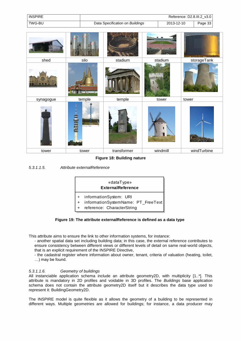
INSPIRE Reference: D2.8.III.2_v3.0
TWG-BU Data Specification on Buildings 2013-12-10 Page 33
shed silo stadium stadium storageTank
synagogue temple temple tower tower
tower tower transformer windmill windTurbine
Figure 18: Building nature
5.3.1.1.5. Attribute externalReference
class Buildings - Base: Data Types
«dataType»
ExternalReference
+ informationSystem: URI
+ informationSystemName: PT_FreeText
+ reference: CharacterString
Figure 19: The attribute externalReference is defined as a data type
This attribute aims to ensure the link to other information systems, for instance:
- another spatial data set including building data; in this case, the external reference contributes to ensure consistency between different views or different levels of detail on same real-world objects, that is an explicit requirement of the INSPIRE Directive, - the cadastral register where information about owner, tenant, criteria of valuation (heating, toilet, …) may be found.
5.3.1.1.6. Geometry of buildings All instanciable application schema include an attribute geometry2D, with multiplicity [1..*]. This attribute is mandatory in 2D profiles and voidable in 3D profiles. The Buildings base application schema does not contain the attribute geometry2D itself but it describes the data type used to represent it: BuildingGeometry2D. The INSPIRE model is quite flexible as it allows the geometry of a building to be represented in different ways. Multiple geometries are allowed for buildings; for instance, a data producer may

INSPIRE Reference: D2.8.III.2_v3.0
TWG-BU Data Specification on Buildings 2013-12-10 Page 34
provide representation of a building as a surface and as a point or as several surfaces, e.g. the building captured by its foot print and by its roof edges. Whereas the representation by surfaces is expected by most use cases, the representation by point is useful to make some computations quicker (e.g. computation of distances). However, a view service may only use one geometry; the geometry to be chosen by the view service is documented through the Boolean attribute referenceGeometry: there shall be only one geometric representation whose attribute referenceGeometry gets the value ―true‖. In case of representation by point and by surface, the surface should generally be the reference geometry.
class Buildings - Base: Main Types
«dataType»
BuildingGeometry2D
+ geometry: GM_Object
+ referenceGeometry: Boolean
+ horizontalGeometryReference: HorizontalGeometryReferenceValue
+ verticalGeometryReference: ElevationReferenceValue [0..1]
«voidable»
+ horizontalGeometryEstimatedAccuracy: Length
+ verticalGeometryEstimatedAccuracy: Length [0..1]
constraints
{referenceGeometry}
{geometryIsPointOrSurfaceOrMultiSurface}
{horizontalGeometryEstimatedAccuracyUoMIsMetre}
{verticalGeometryEstimatedAccuracyUoMIsMetre}
class Buildings - Base: Code Lists
«codeList»
HorizontalGeometryReferenceValue
tags
extensibil ity = none
obligation = implementingRule
vocabulary = http://inspire.ec.europa.eu/codeList/HorizontalGeometryRefrenceValue
above ground envelope, combined, entrance
point, envelope, footprint, lower floor above
ground, point inside building, point inside
cadastral parcel, roof edge.
class Buildings - Base: Code Lists
«codeList»
Elev ationReferenceValue
tags
extensibil ity = none
obligation = implementingRule
vocabulary = http://inspire.ec.europa.eu/codeList/ElevationReferenceValue
above ground envelope, bottom of construction, entrance
point, general eave, general ground, general roof, general
roof edge, highest eave, highest ground point, highest point,
highest roof edge, lowest eave, lowest floor above ground,
lowest ground point, lowest roof edge, top of construction.
Figure 20: The geometry of Building and BuildingPart has to be documented
A building is a 3D object represented in this profile by 2D or 2,5 D data:
− the place where (X,Y) coordinates were captured has to be documented using the attribute horizontalGeometryReference;
− the place where Z coordinate was captured must be documented using the attribute verticalGeometryReference.

INSPIRE Reference: D2.8.III.2_v3.0
TWG-BU Data Specification on Buildings 2013-12-10 Page 35
Figure 21: Examples of HorizontalGeometryReference
NOTE: The possible values of attribute horizontalGeometryReference depend on the geometric representation of the building or building part, as shown in the Table 4 below.
Table 4: Correspondence between geometry and horizontalGeometryReference
geometry GM_Point GM_Surface GM_MultiSurface
horizontalGeometryReference entrancePoint pointInsideBuilding
pointInsideCadastralParcel
Footprint Roofedge
aboveGroundEnvelope envelope
lowestFloorAboveGround combined
NOTE: it is not forbidden to represent different levels of detail of the same building. The model allows for instance to represent the geometries of the building, captured at different scales, using the same horizontal geometry reference., e.g. a building captured by its roof edge with different generalisation rules or from aerial images taken at different original scales. In this case, it is strongly recommended to provide the attribute horizontalGeometryEstimatedAccuracy and/or to give referenceGeometry to the most detailed one.

INSPIRE Reference: D2.8.III.2_v3.0
TWG-BU Data Specification on Buildings 2013-12-10 Page 36
5.3.1.2. UML Overview
class Buildings - Base: Main Types
«featureType»
AbstractBuilding
«voidable»
+ buildingNature: BuildingNatureValue [0..*]
+ currentUse: CurrentUse [0..*]
+ numberOfDwellings: Integer [0..1]
+ numberOfBuildingUnits: Integer [0..1]
+ numberOfFloorsAboveGround: Integer [0..1]
«featureType»
AbstractConstruction
+ inspireId: Identifier
«voidable, l ifeCycleInfo»
+ beginLifespanVersion: DateTime
+ endLifespanVersion: DateTime [0..1]
«voidable»
+ conditionOfConstruction: ConditionOfConstructionValue
+ dateOfConstruction: DateOfEvent [0..1]
+ dateOfDemolition: DateOfEvent [0..1]
+ dateOfRenovation: DateOfEvent [0..1]
+ elevation: Elevation [0..*]
+ externalReference: ExternalReference [0..*]
+ heightAboveGround: HeightAboveGround [0..*]
+ name: GeographicalName [0..*]
«featureType»
Building«featureType»
BuildingPart
«dataType»
BuildingGeometry2D
+ geometry: GM_Object
+ referenceGeometry: Boolean
+ horizontalGeometryReference: HorizontalGeometryReferenceValue
+ verticalGeometryReference: ElevationReferenceValue [0..1]
«voidable»
+ horizontalGeometryEstimatedAccuracy: Length
+ verticalGeometryEstimatedAccuracy: Length [0..1]
constraints
{referenceGeometry}
{geometryIsPointOrSurfaceOrMultiSurface}
{horizontalGeometryEstimatedAccuracyUoMIsMetre}
{verticalGeometryEstimatedAccuracyUoMIsMetre}
+parts
«voidable»
0..*
Figure 22: UML class diagram: Overview of the Building Base - Main types

INSPIRE Reference: D2.8.III.2_v3.0
TWG-BU Data Specification on Buildings 2013-12-10 Page 37
class Buildings - Base: Data Types
«dataType»
ExternalReference
+ informationSystem: URI
+ informationSystemName: PT_FreeText
+ reference: CharacterString
«dataType»
CurrentUse
+ currentUse: CurrentUseValue
«voidable»
+ percentage: Integer
constraints
{percentageSum}
«dataType»
HeightAbov eGround
+ value: Length
«voidable»
+ heightReference: ElevationReferenceValue
+ lowReference: ElevationReferenceValue
+ status: HeightStatusValue
constraints
{valueUoMIsMetre}
«dataType»
DateOfEv ent
«voidable»
+ anyPoint: DateTime [0..1]
+ beginning: DateTime [0..1]
+ end: DateTime [0..1]
constraints
{atLeastOneEvent}
{beginning is before anyPoint is before end}
«dataType»
Elev ation
+ elevationReference: ElevationReferenceValue
+ elevationValue: DirectPosition
Figure 23: UML class diagram: Overview of the Building Base - Data types

INSPIRE Reference: D2.8.III.2_v3.0
TWG-BU Data Specification on Buildings 2013-12-10 Page 38
class Buildings - Base: Code Lists
«codeList»
Elev ationReferenceValue
tags
extensibil ity = none
obligation = implementingRule
vocabulary = http://inspire.ec.europa.eu/codeList/ElevationReferenceValue
«codeList»
CurrentUseValue
tags
extensiblity = narrower
obligation = implementingRule
vocabulary = http://inspire.ec.europa.eu/codeList/CurrentUseValue
«codeList»
BuildingNatureValue
tags
extensibil ity = any
obligation = implementingRule
vocabulary = http://inspire.ec.europa.eu/codeList/BuildingNatureValue
«codeList»
HorizontalGeometryReferenceValue
tags
extensibil ity = none
obligation = implementingRule
vocabulary = http://inspire.ec.europa.eu/codeList/HorizontalGeometryRefrenceValue
«codeList»
HeightStatusValue
tags
extensibil ity = none
obligation = implementingRule
vocabulary = http://inspire.ec.europa.eu/codeList/HeightStatusValue
«codeList»
ConditionOfConstructionValue
tags
extensibil ity = none
obligation = implementingRule
vocabulary = http://inspire.ec.europa.eu/codeList/ConditionOfConstructionValue
residential
individualResidence
collectiveResidence
twoDwellings
moreThanTwoDwellings
residenceFor Communities
agriculture
industrial
commerceAndServices
office
trade
publicServices
ancillary
arch, bunker, canopy, castle, cave building, chapel,
church, dam, greenhouse, l ighthouse, mosque, shed,
silo, stadium, storage tank, synagogue, temple, tower,
windmill, wind turbine.
above ground envelope, combined, entrance
point, envelope, footprint, lower floor above
ground, point inside building, point inside
cadastral parcel, roof edge.
declined, demolished,
functional, projected,
ruin, under
construction.
estimated, measured.
above ground envelope, bottom of construction, entrance
point, general eave, general ground, general roof, general
roof edge, highest eave, highest ground point, highest point,
highest roof edge, lowest eave, lowest floor above ground,
lowest ground point, lowest roof edge, top of construction.
Figure 24: UML class diagram: Overview of the Building Base - Code lists
5.3.1.3. Consistency between spatial data sets There should be some consistency between the value of attribute currentUse in theme Buildings and the location of agricultural facilities, industrial or production facilities and governmental services. Typically:
- Buildings within an agricultural or aquacultural facility should generally have value ―agricultural‖ for attribute current use
- Buildings within an industrial or production facility should generally have value ―industrial‖ for attribute current use
- Buildings within a governmental service should generally have value ―public services‖ for attribute current use
However, there may be exceptions (e.g. a residential building for guardian in a production site or for teacher in a school or for farmer in an agricultural facility); moreover, the geometry of facilities or
INSPIRE Reference: D2.8.III.2_v3.0
TWG-BU Data Specification on Buildings 2013-12-10 Page 39
governmental services may be represented in some cases just by a point and so, may not always enable to identified the related buildings. Consequently, no absolute consistency rule can be provided.
Recommendation 8 Member States and/or National Spatial Data Infrastructures should encourage cooperation between data providers of themes Buildings and of themes Agricultural and Aquacultural Facilities, Production and Industrial facilities and Utility and Governmental Services in order to provide consistent data.
5.3.1.4. Identifier management The buildings and building parts have to be identified by the mandatory attribute inspireID; this unique identification enables the buildings and building parts to be target of associations from other INSPIRE themes, e.g. from theme Address.
5.3.1.5. Modelling of object references The base application schema offers one option to link a spatial object (building or building part) defined in INSPIRE to information in other systems: the attribute externalReference provides the identifier/reference of the object in that foreign system together with the name and the URI of that information system. This external reference for instance may be used to obtain information about the owner of the building from a cadastral system. The external information systems that may/should be linked to theme Buildings depend of course of national context and regulations.
Recommendation 9 Member States and/or National Spatial Data Infrastructures should agree on the external information systems to be linked to theme Buildings.

INSPIRE Reference: D2.8.III.2_v3.0
TWG-BU Data Specification on Buildings 2013-12-10 Page 40
5.3.2 Feature catalogue
Feature catalogue metadata
Application Schema INSPIRE Application Schema BuildingsBase
Version number 3.0
Types defined in the feature catalogue
Type Package Stereotypes
AbstractBuilding BuildingsBase «featureType»
AbstractConstruction BuildingsBase «featureType»
Building BuildingsBase «featureType»
BuildingGeometry2D BuildingsBase «dataType»
BuildingNatureValue BuildingsBase «codeList»
BuildingPart BuildingsBase «featureType»
ConditionOfConstructionValue BuildingsBase «codeList»
CurrentUse BuildingsBase «dataType»
CurrentUseValue BuildingsBase «codeList»
DateOfEvent BuildingsBase «dataType»
Elevation BuildingsBase «dataType»
ElevationReferenceValue BuildingsBase «codeList»
ExternalReference BuildingsBase «dataType»
HeightAboveGround BuildingsBase «dataType»
HeightStatusValue BuildingsBase «codeList»
HorizontalGeometryReferenceValue BuildingsBase «codeList»
5.3.2.1. Spatial object types
5.3.2.1.1. AbstractConstruction
AbstractConstruction (abstract)
Name: Abstract construction Definition: Abstract spatial object type grouping the semantic properties of buildings,
building parts and of some optional spatial object types that may be added in order to provide more information about the theme Buildings.
Description: The optional spatial object types that may be added to core profiles are described in the extended profiles. The ones inheriting from the attributes of AbstractConstruction are Installation and OtherConstruction.
Stereotypes: «featureType»
Attribute: beginLifespanVersion
Name: Begin lifespan version Value type: DateTime Definition: Date and time at which this version of the spatial object was inserted or changed
in the spatial data set. Multiplicity: 1 Stereotypes: «voidable,lifeCycleInfo»
Attribute: conditionOfConstruction
Name: Condition of construction Value type: ConditionOfConstructionValue Definition: Status of the construction. Description: EXAMPLES: functional, projected, ruin

INSPIRE Reference: D2.8.III.2_v3.0
TWG-BU Data Specification on Buildings 2013-12-10 Page 41
AbstractConstruction (abstract)
Multiplicity: 1 Stereotypes: «voidable»
Attribute: dateOfConstruction
Name: Date of construction Value type: DateOfEvent Definition: Date of construction. Multiplicity: 0..1 Stereotypes: «voidable»
Attribute: dateOfDemolition
Name: Date of demolition Value type: DateOfEvent Definition: Date of demolition. Multiplicity: 0..1 Stereotypes: «voidable»
Attribute: dateOfRenovation
Name: Date of last major renovation Value type: DateOfEvent Definition: Date of last major renovation. Multiplicity: 0..1 Stereotypes: «voidable»
Attribute: elevation
Name: Elevation Value type: Elevation Definition: Vertically-constrained dimensional property consisting of an absolute measure
referenced to a well-defined surface which is commonly taken as origin (geoïd, water level, etc.).
Description: Source: adapted from the definition given in the data specification of the theme Elevation.
Multiplicity: 0..* Stereotypes: «voidable»
Attribute: endLifespanVersion
Name: End lifespan version Value type: DateTime Definition: Date and time at which this version of the spatial object was superseded or
retired in the spatial data set. Multiplicity: 0..1 Stereotypes: «voidable,lifeCycleInfo»
Attribute: externalReference
Name: External reference Value type: ExternalReference Definition: Reference to an external information system containing any piece of information
related to the spatial object. Description: EXAMPLE 1: Reference to another spatial data set containing another view on
buildings; the externalReference may be used for instance to ensure consistency between 2D and 3D representations of the same buildings EXAMPLE 2: Reference to cadastral or dwelling register. The reference to this register may enable to find legal information related to the building, such as the

INSPIRE Reference: D2.8.III.2_v3.0
TWG-BU Data Specification on Buildings 2013-12-10 Page 42
AbstractConstruction (abstract)
owner(s) or valuation criteria (e.g. type of heating, toilet, kitchen) EXAMPLE 3: Reference to the system recording the building permits. The reference to the building permits may be used to find detailed information about the building physical and temporal aspects.
Multiplicity: 0..* Stereotypes: «voidable»
Attribute: heightAboveGround
Name: Height above ground Value type: HeightAboveGround Definition: Height above ground. Description: NOTE: height above ground may be defined as the difference between elevation
at a low reference (ground level) and elevation as a high reference (e.g. roof level, top of construction)
Multiplicity: 0..* Stereotypes: «voidable»
Attribute: inspireId
Name: inspire id Value type: Identifier Definition: External object identifier of the spatial object. Description: An external object identifier is a unique object identifier published by the
responsible body, which may be used by external applications to reference the spatial object. The identifier is an identifier of the spatial object, not an identifier of the real-world phenomenon.
Multiplicity: 1
Attribute: name
Value type: GeographicalName Definition: Name of the construction. Description: EXAMPLES: Big Ben, Eiffel Tower, Sacrada Familia Multiplicity: 0..* Stereotypes: «voidable»
5.3.2.1.2. AbstractBuilding
AbstractBuilding (abstract)
Name: Abstract building Subtype of: AbstractConstruction Definition: Abstract spatial object type grouping the common semantic properties of the
spatial object types Building and BuildingPart. Stereotypes: «featureType»
Attribute: buildingNature
Name: Building nature Value type: BuildingNatureValue Definition: Characteristic of the building that makes it generally of interest for mappings
applications. The characteristic may be related to the physical aspect and/or to the function of the building.
Description: This attribute focuses on the physical aspect of the building; however, this physical aspect is often expressed as a function (e.g. stadium, silo, windmill); this attribute aims to fulfil mainly mapping purposes and addresses only specific, noticeable buildings.
Multiplicity: 0..*
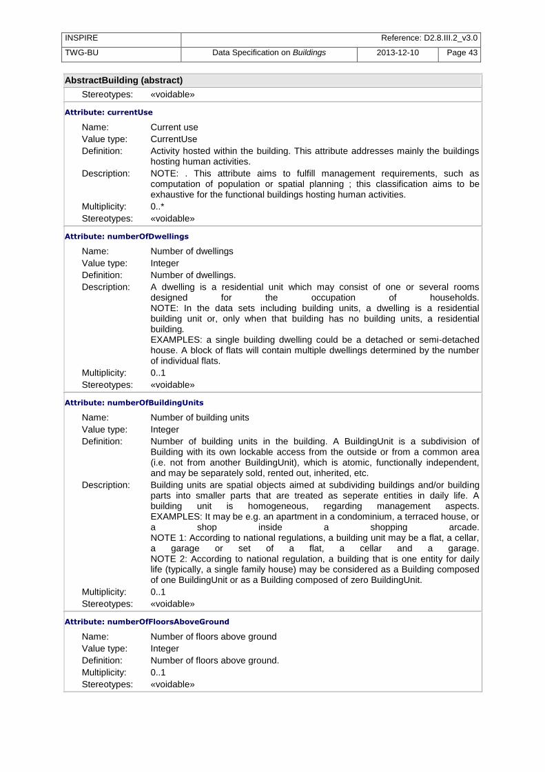
INSPIRE Reference: D2.8.III.2_v3.0
TWG-BU Data Specification on Buildings 2013-12-10 Page 43
AbstractBuilding (abstract)
Stereotypes: «voidable»
Attribute: currentUse
Name: Current use Value type: CurrentUse Definition: Activity hosted within the building. This attribute addresses mainly the buildings
hosting human activities. Description: NOTE: . This attribute aims to fulfill management requirements, such as
computation of population or spatial planning ; this classification aims to be exhaustive for the functional buildings hosting human activities.
Multiplicity: 0..* Stereotypes: «voidable»
Attribute: numberOfDwellings
Name: Number of dwellings Value type: Integer Definition: Number of dwellings. Description: A dwelling is a residential unit which may consist of one or several rooms
designed for the occupation of households. NOTE: In the data sets including building units, a dwelling is a residential building unit or, only when that building has no building units, a residential building. EXAMPLES: a single building dwelling could be a detached or semi-detached house. A block of flats will contain multiple dwellings determined by the number of individual flats.
Multiplicity: 0..1 Stereotypes: «voidable»
Attribute: numberOfBuildingUnits
Name: Number of building units Value type: Integer Definition: Number of building units in the building. A BuildingUnit is a subdivision of
Building with its own lockable access from the outside or from a common area (i.e. not from another BuildingUnit), which is atomic, functionally independent, and may be separately sold, rented out, inherited, etc.
Description: Building units are spatial objects aimed at subdividing buildings and/or building parts into smaller parts that are treated as seperate entities in daily life. A building unit is homogeneous, regarding management aspects. EXAMPLES: It may be e.g. an apartment in a condominium, a terraced house, or a shop inside a shopping arcade. NOTE 1: According to national regulations, a building unit may be a flat, a cellar, a garage or set of a flat, a cellar and a garage. NOTE 2: According to national regulation, a building that is one entity for daily life (typically, a single family house) may be considered as a Building composed of one BuildingUnit or as a Building composed of zero BuildingUnit.
Multiplicity: 0..1 Stereotypes: «voidable»
Attribute: numberOfFloorsAboveGround
Name: Number of floors above ground Value type: Integer Definition: Number of floors above ground. Multiplicity: 0..1 Stereotypes: «voidable»

INSPIRE Reference: D2.8.III.2_v3.0
TWG-BU Data Specification on Buildings 2013-12-10 Page 44
5.3.2.1.3. Building
Building (abstract)
Name: Building Subtype of: AbstractBuilding Definition: A Building is an enclosed construction above and/or underground, used or
intended for the shelter of humans, animals or things or for the production of economic goods. A building refers to any structure permanently constructed or erected on its site.
Stereotypes: «featureType»
Association role: parts
Value type: BuildingPart Definition: The building parts composing the Building. Description: A building may be a simple building (with no BuildingPart) or a composed
building (with several BuildingParts). Multiplicity: 0..* Stereotypes: «voidable»
5.3.2.1.4. BuildingPart
BuildingPart (abstract)
Name: Building part Subtype of: AbstractBuilding Definition: A BuildingPart is a sub-division of a Building that might be considered itself as a
building. Description: NOTE 1: A BuildingPart is homogeneous related to its physical, functional or
temporal aspects. NOTE 2: Building and BuildingPart share the same set of properties. EXAMPLE: A building may be composed of two building parts having different heights above ground.
Stereotypes: «featureType»
5.3.2.2. Data types
5.3.2.2.1. DateOfEvent
DateOfEvent
Name: Date of event Definition: This data type includes the different possible ways to define the date of an event. Stereotypes: «dataType»
Attribute: anyPoint
Name: Any point Value type: DateTime Definition: A date and time of any point of the event, between its beginning and its end. Multiplicity: 0..1 Stereotypes: «voidable»
Attribute: beginning
Name: Beginning Value type: DateTime Definition: Date and time when the event begun. Multiplicity: 0..1 Stereotypes: «voidable»
Attribute: end
Name: End

INSPIRE Reference: D2.8.III.2_v3.0
TWG-BU Data Specification on Buildings 2013-12-10 Page 45
DateOfEvent
Value type: DateTime Definition: Date and time when the event ended. Multiplicity: 0..1 Stereotypes: «voidable»
Constraint: atLeastOneEvent
Natural language:
At least, one of the attributes beginning, end or anyPoint shall be supplied.
OCL: inv: dateOfEvent->notEmpty()
Constraint: beginning is before anyPoint is before end
Natural language:
OCL: inv: beginning <= anyPoint and anyPoint <= end and beginning <= end
5.3.2.2.2. HeightAboveGround
HeightAboveGround
Name: Height above ground Definition: Vertical distance (measured or estimated) between a low reference and a high
reference. Stereotypes: «dataType»
Attribute: heightReference
Name: Height reference Value type: ElevationReferenceValue Definition: Element used as the high reference. Description: EXAMPLE: The height of the building has been captured up to the top of
building. Multiplicity: 1 Stereotypes: «voidable»
Attribute: lowReference
Name: Low reference Value type: ElevationReferenceValue Definition: Element as the low reference. Description: EXAMPLE: the height of the building has been captured from its the lowest
ground point. Multiplicity: 1 Stereotypes: «voidable»
Attribute: status
Name: Status Value type: HeightStatusValue Definition: The way the height has been captured. Multiplicity: 1 Stereotypes: «voidable»
Attribute: value
Name: Value Value type: Length Definition: Value of the height above ground. Multiplicity: 1
Constraint: valueUoMIsMetre

INSPIRE Reference: D2.8.III.2_v3.0
TWG-BU Data Specification on Buildings 2013-12-10 Page 46
HeightAboveGround
Natural language:
Value shall be in meters.
OCL: inv: self.value.uom.uomSymbol='m'
5.3.2.2.3. Elevation
Elevation
Name: Elevation Definition: This data types includes the elevation value itself and information on how this
elevation was measured. Stereotypes: «dataType»
Attribute: elevationReference
Name: Elevation reference Value type: ElevationReferenceValue Definition: Element where the elevation was measured. Multiplicity: 1
Attribute: elevationValue
Name: elevation value Value type: DirectPosition Definition: Value of the elevation. Multiplicity: 1
5.3.2.2.4. BuildingGeometry2D
BuildingGeometry2D
Name: Building geometry 2D Definition: This data types includes the geometry of the building and metadata information
about which element of the building was captured and how. Stereotypes: «dataType»
Attribute: geometry
Name: Geometry Value type: GM_Object Definition: 2D or 2.5D geometric representation Multiplicity: 1
Attribute: referenceGeometry
Name: Reference geometry Value type: Boolean Definition: The geometry to be taken into account by view services, for portrayal. Description: NOTE 1: In case of multiple representation by point and by surface, it is
generally recommended to provide the surface as reference geometry. NOTE 2: The geometric representation whose referenceGeometry is true may also be used preferably for spatial queries by download services (WFS) or by Geographical Information System (GIS).
Multiplicity: 1
Attribute: horizontalGeometryReference
Name: Horizontal geometry reference Value type: HorizontalGeometryReferenceValue Definition: Element of the building that was captured by (X,Y) coordinates. Multiplicity: 1
Attribute: verticalGeometryReference

INSPIRE Reference: D2.8.III.2_v3.0
TWG-BU Data Specification on Buildings 2013-12-10 Page 47
BuildingGeometry2D
Name: Vertical geometry reference Value type: ElevationReferenceValue Definition: Element of the building that was captured by vertical coordinates. Multiplicity: 0..1
Attribute: horizontalGeometryEstimatedAccuracy
Name: Horizontal geometry estimated accuracy Value type: Length Definition: The estimated absolute positional accuracy of the (X,Y) coordinates of the
building geometry, in the INSPIRE official Coordinate Reference System. Absolute positional accuracy is defined as the mean value of the positional uncertainties for a set of positions where the positional uncertainties are defined as the distance between a measured position and what is considered as the corresponding true position.
Description: NOTE: This mean value may come from quality measures on a homogeneous population of buildings or from an estimation based on the knowledge of the production processes and of their accuracy.
Multiplicity: 1 Stereotypes: «voidable»
Attribute: verticalGeometryEstimatedAccuracy
Name: Vertical geometry estimated accuracy Value type: Length Definition: The estimated absolute positional accuracy of the Z coordinates of the building
geometry, in the INSPIRE official Coordinate Reference System. Absolute positional accuracy is defined as the mean value of the positional uncertainties for a set of positions where the positional uncertainties are defined as the distance between a measured position and what is considered as the corresponding true position.
Description: NOTE: This mean value may come from quality measures on a homogeneous population of buildings or from an estimation based on the knowledge of the production processes and of their accuracy.
Multiplicity: 0..1 Stereotypes: «voidable»
Constraint: geometryIsPointOrSurfaceOrMultiSurface
Natural language:
Geometry shall be of type GM_Point or GM_Surface or GM_MultiSurface.
OCL:
Constraint: horizontalGeometryEstimatedAccuracyUoMIsMetre
Natural language:
The value of horizontalGeometryEstimatedAccuracy shall be given in meters.
OCL: inv: self.horizontalGeometryEstimatedAccuracy.uom.uomSymbol='m'
Constraint: referenceGeometry
Natural language:
For exactly one item of BuildingGeometry, the value of the attribute referenceGeometry shall be 'true'.
OCL:
Constraint: verticalGeometryEstimatedAccuracyUoMIsMetre
Natural language:
The Value of verticalGeometryEstimatedAccuracy has to be given in meters.
OCL: inv: self.verticalGeometryEstimatedAccuracy.uom.uomSymbol='m'

INSPIRE Reference: D2.8.III.2_v3.0
TWG-BU Data Specification on Buildings 2013-12-10 Page 48
5.3.2.2.5. CurrentUse
CurrentUse
Name: Current use Definition: This data type enables to detail the current use(s). Stereotypes: «dataType»
Attribute: currentUse
Name: Current use Value type: CurrentUseValue Definition: The current use. Description: EXAMPLE: trade Multiplicity: 1
Attribute: percentage
Name: Percentage Value type: Integer Definition: The proportion of the real world object, given as a percentage, devoted to this
current use. Description: NOTE: The percentage of use is generally the percentage of floor area dedicated
to this given use. If it is not the case, it is recommended to explain what the percentage refers to in metadata (template for additional information) EXAMPLE: 30 (if 30% of the building is occupied by trade activity).
Multiplicity: 1 Stereotypes: «voidable»
Constraint: percentageSum
Natural language:
The total of all percentages shall be less or equal to 100.
OCL: inv: self.percentage.sum()<=100
5.3.2.2.6. ExternalReference
ExternalReference
Name: External reference Definition: Reference to an external information system containing any piece of information
related to the spatial object. Stereotypes: «dataType»
Attribute: informationSystem
Name: Information system Value type: URI Definition: Uniform Resource Identifier of the external information system. Multiplicity: 1
Attribute: informationSystemName
Name: Information system name Value type: PT_FreeText Definition: The name of the external information system. Description: EXAMPLES: Danish Register of Dwellings, Spanish Cadastre. Multiplicity: 1
Attribute: reference
Name: Reference Value type: CharacterString Definition: Thematic identifier of the spatial object or of any piece of information related to
the spatial object.

INSPIRE Reference: D2.8.III.2_v3.0
TWG-BU Data Specification on Buildings 2013-12-10 Page 49
ExternalReference
Description: NOTE: This reference will act as a foreign key to implement the association between the spatial object in the INSPIRE data set and in the external information system. EXAMPLE: The cadastral reference of a given building in the national cadastral register.
Multiplicity: 1
5.3.2.3. Code lists
5.3.2.3.1. ConditionOfConstructionValue
ConditionOfConstructionValue
Name: Condition of construction value Definition: Values indicating the condition of a construction. Extensibility: none Identifier: http://inspire.ec.europa.eu/codelist/ConditionOfConstructionValue Values: The allowed values for this code list comprise only the values specified in Annex
C .
5.3.2.3.2. HeightStatusValue
HeightStatusValue
Name: Height status value Definition: Values indicating the method used to capture a height. Extensibility: none Identifier: http://inspire.ec.europa.eu/codelist/HeightStatusValue Values: The allowed values for this code list comprise only the values specified in Annex
C .
5.3.2.3.3. ElevationReferenceValue
ElevationReferenceValue
Name: Elevation reference value Definition: List of possible elements considered to capture a vertical geometry. Description: NOTE: The values of this code list are used to describe the reference of
elevation both where elevation has been captured as attribute or as Z coordinate.
Extensibility: none Identifier: http://inspire.ec.europa.eu/codelist/ElevationReferenceValue Values: The allowed values for this code list comprise only the values specified in Annex
C .
5.3.2.3.4. CurrentUseValue
CurrentUseValue
Name: Current use value Definition: List of possible values indicating the current use. Description: SOURCE: This code list is partly based on and adapted from the Eurostat
classification of types of constructions (for the classification of residential buildings). NOTE: the values of this code list apply to buildings or building components where building components may be a building part (in core profiles) or a building unit (in extended profiles)
Extensibility: narrower Identifier: http://inspire.ec.europa.eu/codelist/CurrentUseValue Values: The allowed values for this code list comprise the values specified in Annex C
and narrower values defined by data providers.

INSPIRE Reference: D2.8.III.2_v3.0
TWG-BU Data Specification on Buildings 2013-12-10 Page 50
5.3.2.3.5. BuildingNatureValue
BuildingNatureValue
Name: Building nature value Definition: Values indicating the nature of a building. Description: NOTE 1 : This code list does not aim to be exhaustive as the attribute
buildingNature addresses only noticeable buildings. NOTE 2: The values included in this code list address mainly (but not only) two international use cases: air flights where buildings may be obstacles and marine navigation where buildings may be landmarks. NOTE 3: This code list should only be applied for buildings, even if it may be applicable to other constructions (for example, not all dams are buildings).
Extensibility: open Identifier: http://inspire.ec.europa.eu/codelist/BuildingNatureValue Values: The allowed values for this code list comprise the values specified in Annex C
and additional values at any level defined by data providers.
5.3.2.3.6. HorizontalGeometryReferenceValue
HorizontalGeometryReferenceValue
Name: Horizontal geometry reference value Definition: Values indicating the element considered to capture a horizontal geometry. Extensibility: none Identifier: http://inspire.ec.europa.eu/codelist/HorizontalGeometryRefrenceValue Values: The allowed values for this code list comprise only the values specified in Annex
C .
5.3.2.4. Imported types (informative)
This section lists definitions for feature types, data types and enumerations and code lists that are defined in other application schemas. The section is purely informative and should help the reader understand the feature catalogue presented in the previous sections. For the normative documentation of these types, see the given references.
5.3.2.4.1. Boolean
Boolean
Package: Truth Reference: Geographic information -- Conceptual schema language [ISO/TS 19103:2005]
5.3.2.4.2. CharacterString
CharacterString
Package: Text Reference: Geographic information -- Conceptual schema language [ISO/TS 19103:2005]
5.3.2.4.3. DateTime
DateTime
Package: Date and Time Reference: Geographic information -- Conceptual schema language [ISO/TS 19103:2005]
5.3.2.4.4. DirectPosition
DirectPosition
Package: Coordinate geometry Reference: Geographic information -- Spatial schema [ISO 19107:2003]
5.3.2.4.5. GM_Object
GM_Object (abstract)
Package: Geometry root Reference: Geographic information -- Spatial schema [ISO 19107:2003]

INSPIRE Reference: D2.8.III.2_v3.0
TWG-BU Data Specification on Buildings 2013-12-10 Page 51
5.3.2.4.6. GeographicalName
GeographicalName
Package: Geographical Names Reference: INSPIRE Data specification on Geographical Names [DS-D2.8.I.3] Definition: Proper noun applied to a real world entity.
5.3.2.4.7. Identifier
Identifier
Package: Base Types Reference: INSPIRE Generic Conceptual Model, version 3.4 [DS-D2.5] Definition: External unique object identifier published by the responsible body, which may
be used by external applications to reference the spatial object. Description: NOTE1 External object identifiers are distinct from thematic object identifiers.
NOTE 2 The voidable version identifier attribute is not part of the unique identifier of a spatial object and may be used to distinguish two versions of the same spatial object. NOTE 3 The unique identifier will not change during the life-time of a spatial object.
5.3.2.4.8. Integer
Integer
Package: Numerics Reference: Geographic information -- Conceptual schema language [ISO/TS 19103:2005]
5.3.2.4.9. Length
Length
Package: Units of Measure Reference: Geographic information -- Conceptual schema language [ISO/TS 19103:2005]
5.3.2.4.10. PT_FreeText
PT_FreeText
Package: Cultural and linguistic adapdability Reference: Geographic information -- Metadata -- XML schema implementation [ISO/TS
19139:2007]
5.3.2.4.11. URI
URI
Package: basicTypes Reference: Geographic information -- Geography Markup Language (GML) [ISO
19136:2007]

INSPIRE Reference: D2.8.III.2_v3.0
TWG-BU Data Specification on Buildings 2013-12-10 Page 52
5.4 Application schema Buildings2D
5.4.1 Description
5.4.1.1. Narrative description The Buildings 2D application schema inherits of the semantics of Buildings base application schema and defines the geometric representation of buildings and building parts, using the data type BuildingGeometry2D, also defined in the Buildings Base application schema.
class Buildings - Core 2D
«featureType»
BuildingsBase::AbstractBuilding
«voidable»
+ buildingNature: BuildingNatureValue [0..*]
+ currentUse: CurrentUse [0..*]
+ numberOfDwellings: Integer [0..1]
+ numberOfBuildingUnits: Integer [0..1]
+ numberOfFloorsAboveGround: Integer [0..1]
«featureType»
Building
+ geometry2D: BuildingGeometry2D
constraints
{singleReferenceGeometry}
{Building parts shall be 2D}
«featureType»
BuildingPart
+ geometry2D: BuildingGeometry2D [1..*]
constraints
{singleReferenceGeometry}
«dataType»
BuildingsBase::BuildingGeometry2D
+ geometry: GM_Object
+ referenceGeometry: Boolean
+ horizontalGeometryReference: HorizontalGeometryReferenceValue
+ verticalGeometryReference: ElevationReferenceValue [0..1]
«voidable»
+ horizontalGeometryEstimatedAccuracy: Length
+ verticalGeometryEstimatedAccuracy: Length [0..1]
constraints
{referenceGeometry}
{geometryIsPointOrSurfaceOrMultiSurface}
{horizontalGeometryEstimatedAccuracyUoMIsMetre}
{verticalGeometryEstimatedAccuracyUoMIsMetre}
«featureType»
BuildingsBase::AbstractConstruction
+ inspireId: Identifier
«voidable, l i feCycleInfo»
+ beginLifespanVersion: DateTime
+ endLifespanVersion: DateTime [0..1]
«voidable»
+ conditionOfConstruction: ConditionOfConstructionValue
+ dateOfConstruction: DateOfEvent [0..1]
+ dateOfDemolition: DateOfEvent [0..1]
+ dateOfRenovation: DateOfEvent [0..1]
+ elevation: Elevation [0..*]
+ externalReference: ExternalReference [0..*]
+ heightAboveGround: HeightAboveGround [0..*]
+ name: GeographicalName [0..*]
Buildings - Base
«featureType»
BuildingsBase::
BuildingPart
«featureType»
BuildingsBase::
Building
+parts
«voidable»
0..*
Figure 25: The Buildings 2D application schema
Multiple geometries are allowed for buildings; for instance, a data producer may provide representation of a building as a surface and as a point or as several surfaces, e.g. the building captured by its foot print and by its roof edges.

INSPIRE Reference: D2.8.III.2_v3.0
TWG-BU Data Specification on Buildings 2013-12-10 Page 53
NOTE : the 2D application schema requires that both the geometry of the Building and of BuildingPart have to be provided (multiplicity [1..*]). In some cases, the value ―combined‖ may be used to provide the horizontal geometry reference of Building, as shown in following illustration.
Figure 26: Example for value “combined”
5.4.1.2. UML Overview See previous Figure 25: The Buildings 2D application schema.
5.4.1.3. Consistency between spatial data sets The 2D building geometry may be used as reference geometry by governmental services in INSPIRE theme US; if this option is chosen by the data provider of US theme, this will ensure consistency between themes BU and US and will enable users to find a more detailed classification of the buildings hosting public services.
5.4.1.4. Geometry representation The geometric representation of buildings and building parts has to be provided using the data type BuildingGeometry2D that is defined in <Buildings Base> application schema. It is reminded that this spatial properties allowed in this data types are restricted to Simple Feature v1.2.1 as defined by OGC document 06-103r4, i.e. to 0D, 1D, 2D and 2,5D data.
Recommendation 10 There should not be topological overlaps between buildings having same temporal validity.
NOTE 1: Topological overlaps are the overlaps which occur in the dataset without occurring in the real world, i.e. the overlaps due to bad quality of data. NOTE 2: Overlaps may occur in the data set between buildings and/or building parts, due to the 2D (or 2,5D) representation of 3D real world objects.
BuildingPart A was captured by its footprint. BuildingPart B was captured by its lowest floor above ground. The Building geometry was obtained by merging the geometries of A and B. The horizontal geometry reference of the
building will be combined.
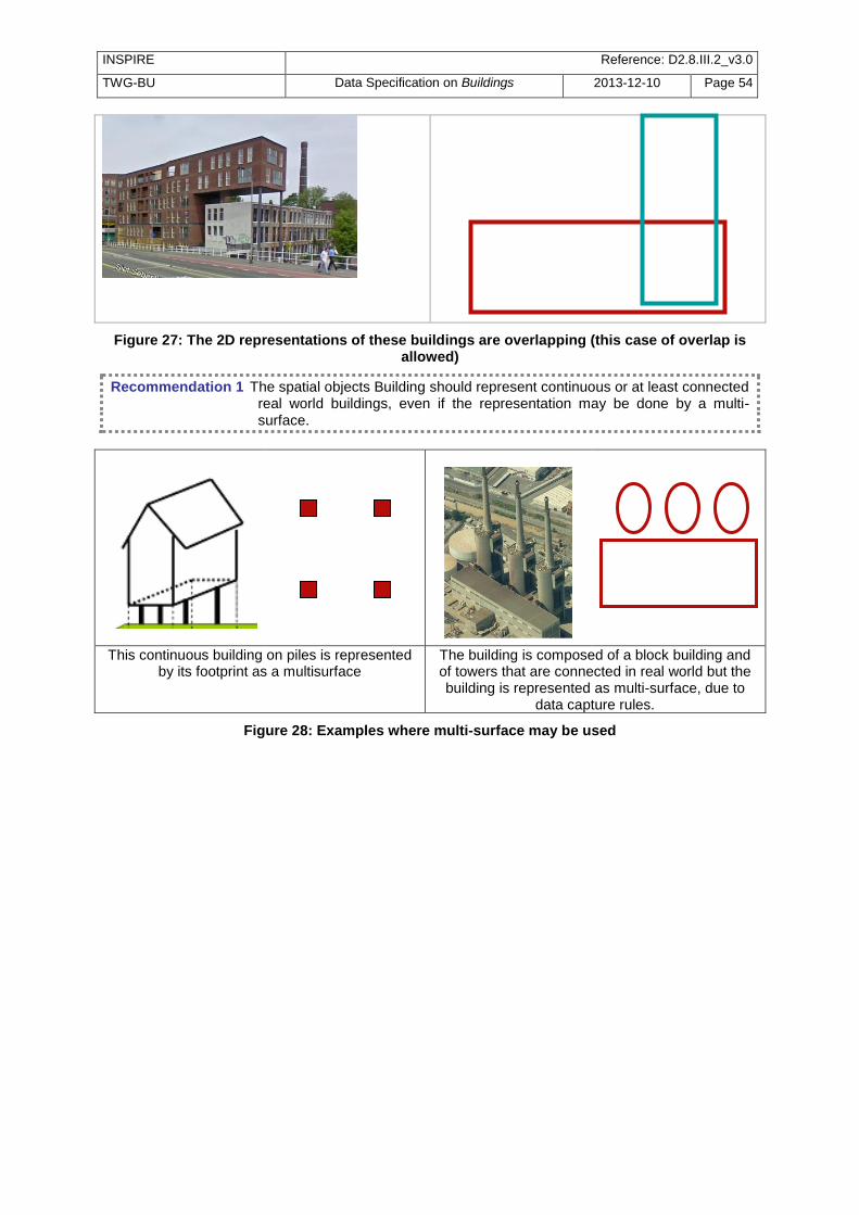
INSPIRE Reference: D2.8.III.2_v3.0
TWG-BU Data Specification on Buildings 2013-12-10 Page 54
Figure 27: The 2D representations of these buildings are overlapping (this case of overlap is allowed)
Recommendation 1 The spatial objects Building should represent continuous or at least connected real world buildings, even if the representation may be done by a multi-surface.
This continuous building on piles is represented by its footprint as a multisurface
The building is composed of a block building and of towers that are connected in real world but the building is represented as multi-surface, due to
data capture rules.
Figure 28: Examples where multi-surface may be used

INSPIRE Reference: D2.8.III.2_v3.0
TWG-BU Data Specification on Buildings 2013-12-10 Page 55
5.4.2 Feature catalogue
Feature catalogue metadata
Application Schema INSPIRE Application Schema Buildings2D
Version number 3.0
Types defined in the feature catalogue
Type Package Stereotypes
Building Buildings2D «featureType»
BuildingPart Buildings2D «featureType»
5.4.2.1. Spatial object types
5.4.2.1.1. Building
Building
Name: Building Subtype of: Building Definition: A Building is an enclosed construction above and/or underground, used or
intended for the shelter of humans, animals or things or for the production of economic goods. A building refers to any structure permanently constructed or erected on its site.
Stereotypes: «featureType»
Attribute: geometry2D
Name: Geometry 2D Value type: BuildingGeometry2D Definition: 2D or 2.5D geometric representation of the building. Description: NOTE: Multiple representations of the geometry are possible (e.g. by surface
and by point). Multiplicity: 1
Constraint: Building parts shall be 2D
Natural language:
The parts of the building shall be represented using the BuildingPart type of the Buildings2D package.
OCL: inv: self.parts->oclIsKindOf(Buildings2D::BuildingPart)
Constraint: singleReferenceGeometry
Natural language:
Exactly one geometry2D attribute must be a reference geometry, i.e. the referenceGeometry attribute must be 'true'.
OCL: inv: self.geometry2D->select(referenceGeometry=true)->size() = 1
5.4.2.1.2. BuildingPart
BuildingPart
Name: Building part Subtype of: BuildingPart Definition: A BuildingPart is a sub-division of a Building that might be considered itself as a
building. Description: NOTE 1: A BuildingPart is homogeneous related to its physical, functional or
temporal aspects. NOTE 2: Building and BuildingPart share the same set of properties. EXAMPLE: A building may be composed of two building parts having different heights above ground.
Stereotypes: «featureType»

INSPIRE Reference: D2.8.III.2_v3.0
TWG-BU Data Specification on Buildings 2013-12-10 Page 56
BuildingPart
Attribute: geometry2D
Name: Geometry 2D Value type: BuildingGeometry2D Definition: 2D or 2.5D geometric representation of the building part. Description:
NOTE: Multiple representations of the geometry are possible (e.g. by surface and by point).
Multiplicity: 1..*
Constraint: singleReferenceGeometry
Natural language:
Exactly one geometry2D attribute must be a reference geometry, i.e. the referenceGeometry attribute must be 'true'.
OCL: inv: self.geometry2D->select(referenceGeometry=true)->size() = 1
5.4.2.2. Imported types (informative)
This section lists definitions for feature types, data types and enumerations and code lists that are defined in other application schemas. The section is purely informative and should help the reader understand the feature catalogue presented in the previous sections. For the normative documentation of these types, see the given references.
5.4.2.2.1. BuildingGeometry2D
BuildingGeometry2D
Package: BuildingsBase Reference: INSPIRE Data specification on Buildings [DS-D2.8.III.2] Definition: This data types includes the geometry of the building and metadata information
about which element of the building was captured and how.
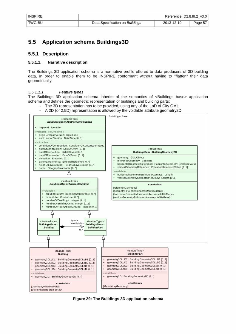
INSPIRE Reference: D2.8.III.2_v3.0
TWG-BU Data Specification on Buildings 2013-12-10 Page 57
5.5 Application schema Buildings3D
5.5.1 Description
5.5.1.1. Narrative description The Buildings 3D application schema is a normative profile offered to data producers of 3D building data, in order to enable them to be INSPIRE conformant without having to "flatten" their data geometrically.
5.5.1.1.1. Feature types The Buildings 3D application schema inherits of the semantics of <Buildings base> application schema and defines the geometric representation of buildings and building parts:
- The 3D representation has to be provided, using any of the LoD of City GML - A 2D (or 2,5D) representation is allowed by the voidable attribute geometry2D
class Buildings - Core 3D
«featureType»
BuildingsBase::AbstractBuilding
«voidable»
+ buildingNature: BuildingNatureValue [0..*]
+ currentUse: CurrentUse [0..*]
+ numberOfDwellings: Integer [0..1]
+ numberOfBuildingUnits: Integer [0..1]
+ numberOfFloorsAboveGround: Integer [0..1]
«dataType»
BuildingsBase::BuildingGeometry2D
+ geometry: GM_Object
+ referenceGeometry: Boolean
+ horizontalGeometryReference: HorizontalGeometryReferenceValue
+ verticalGeometryReference: ElevationReferenceValue [0..1]
«voidable»
+ horizontalGeometryEstimatedAccuracy: Length
+ verticalGeometryEstimatedAccuracy: Length [0..1]
constraints
{referenceGeometry}
{geometryIsPointOrSurfaceOrMultiSurface}
{horizontalGeometryEstimatedAccuracyUoMIsMetre}
{verticalGeometryEstimatedAccuracyUoMIsMetre}
«featureType»
BuildingsBase::AbstractConstruction
+ inspireId: Identifier
«voidable, l ifeCycleInfo»
+ beginLifespanVersion: DateTime
+ endLifespanVersion: DateTime [0..1]
«voidable»
+ conditionOfConstruction: ConditionOfConstructionValue
+ dateOfConstruction: DateOfEvent [0..1]
+ dateOfDemolition: DateOfEvent [0..1]
+ dateOfRenovation: DateOfEvent [0..1]
+ elevation: Elevation [0..*]
+ externalReference: ExternalReference [0..*]
+ heightAboveGround: HeightAboveGround [0..*]
+ name: GeographicalName [0..*]
Buildings - Base
«featureType»
Building
+ geometry3DLoD1: BuildingGeometry3DLoD1 [0..1]
+ geometry3DLoD2: BuildingGeometry3DLoD2 [0..1]
+ geometry3DLoD3: BuildingGeometry3DLoD [0..1]
+ geometry3DLoD4: BuildingGeometry3DLoD [0..1]
«voidable»
+ geometry2D: BuildingGeometry2D [0..*]
constraints
{GeometryWhenNoParts}
{Building parts shall be 3D}
«featureType»
BuildingPart
+ geometry3DLoD1: BuildingGeometry3DLoD1 [0..1]
+ geometry3DLoD2: BuildingGeometry3DLoD2 [0..1]
+ geometry3DLoD3: BuildingGeometry3DLoD [0..1]
+ geometry3DLoD4: BuildingGeometry3DLoD [0..1]
«voidable»
+ geometry2D: BuildingGeometry2D [0..*]
constraints
{MandatoryGeometry}
«featureType»
BuildingsBase::
Building
«featureType»
BuildingsBase::
BuildingPart
+parts
«voidable»
0..*
Figure 29: The Buildings 3D application schema

INSPIRE Reference: D2.8.III.2_v3.0
TWG-BU Data Specification on Buildings 2013-12-10 Page 58
Buildings and building parts may be represented using any of the four levels of detail of City GML:
a. in LoD1, a Building (or BuildingPart) is represented in a generalized way as right prism with vertical walls and horizontal ‗roofs‘. Such a model can be generated by vertically extruding a horizontal base polygon. It is often called ―block model‖
b. in LoD2, a Building or BuildingPart is represented by a generalised way with vertical lateral surfaces and a prototypical roof or cover shape
c. inLod3 and LoD4, a Building or BuildingPart is represented by its real detailed shape for lateral faces (including protrusions, facade elements, and window recesses) as well as of the roof (including dormers, chimneys)
NOTE 1: The outer geometry of buildings in LoD3 and LoD4 is the same. NOTE 2: the Buildings3D model allows to provide the four levels of City GML. However, it is very likely that data producers having LoD3 or LoD4 data will have more information about buildings than the content of this profile (e.g. description of the boundary surfaces, textures). In this case, the extended 3D profile will be more relevant. The representation of Buildings in INSPIRE is based on the 4 levels of detail of City GML.
Figure 30: The 4 levels of detail of City GML
This means that it is possible, for instance:
o to choose one LoD and to use it for all buildings in the data set o to use, in same data set, LoD1 for some buildings, LoD2 for some others and LoD3 or
LoD4 for the last ones. o to have, in same data set, several representations for the same building (e.g. one in LoD2
and one in LoD3) Typically, in many existing data, ordinary buildings are represented using LoD1 or LoD2 whereas noticeable buildings or buildings in a project area will be represented with more details (LoD2, LoD3 or even LoD4). The Buildings3D application schema only imposes that, at least, one of the mandatory geometries (i.e. LoD1, 2, 3 or 4 as solid or as multi-surface) is provided. This is indicated by a constraint.
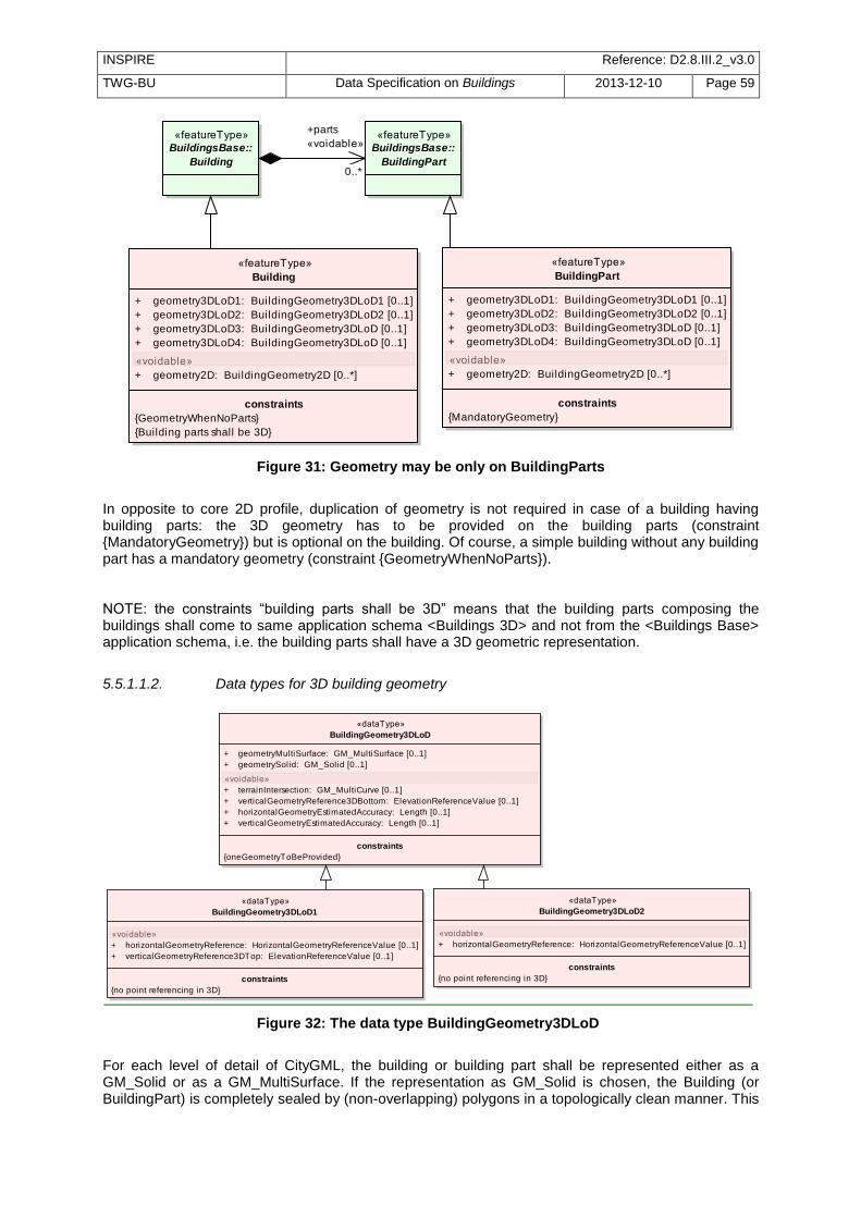
INSPIRE Reference: D2.8.III.2_v3.0
TWG-BU Data Specification on Buildings 2013-12-10 Page 59
class Buildings - Core 3D
«featureType»
Building
+ geometry3DLoD1: BuildingGeometry3DLoD1 [0..1]
+ geometry3DLoD2: BuildingGeometry3DLoD2 [0..1]
+ geometry3DLoD3: BuildingGeometry3DLoD [0..1]
+ geometry3DLoD4: BuildingGeometry3DLoD [0..1]
«voidable»
+ geometry2D: BuildingGeometry2D [0..*]
constraints
{GeometryWhenNoParts}
{Building parts shall be 3D}
«featureType»
BuildingPart
+ geometry3DLoD1: BuildingGeometry3DLoD1 [0..1]
+ geometry3DLoD2: BuildingGeometry3DLoD2 [0..1]
+ geometry3DLoD3: BuildingGeometry3DLoD [0..1]
+ geometry3DLoD4: BuildingGeometry3DLoD [0..1]
«voidable»
+ geometry2D: BuildingGeometry2D [0..*]
constraints
{MandatoryGeometry}
«featureType»
BuildingsBase::
Building
«featureType»
BuildingsBase::
BuildingPart
+parts
«voidable»
0..*
Figure 31: Geometry may be only on BuildingParts
In opposite to core 2D profile, duplication of geometry is not required in case of a building having building parts: the 3D geometry has to be provided on the building parts (constraint {MandatoryGeometry}) but is optional on the building. Of course, a simple building without any building part has a mandatory geometry (constraint {GeometryWhenNoParts}). NOTE: the constraints ―building parts shall be 3D‖ means that the building parts composing the buildings shall come to same application schema <Buildings 3D> and not from the <Buildings Base> application schema, i.e. the building parts shall have a 3D geometric representation.
5.5.1.1.2. Data types for 3D building geometry
class Buildings - Core 3D
«dataType»
BuildingGeometry3DLoD1
«voidable»
+ horizontalGeometryReference: HorizontalGeometryReferenceValue [0..1]
+ verticalGeometryReference3DTop: ElevationReferenceValue [0..1]
constraints
{no point referencing in 3D}
«dataType»
BuildingGeometry3DLoD
+ geometryMultiSurface: GM_MultiSurface [0..1]
+ geometrySolid: GM_Solid [0..1]
«voidable»
+ terrainIntersection: GM_MultiCurve [0..1]
+ verticalGeometryReference3DBottom: ElevationReferenceValue [0..1]
+ horizontalGeometryEstimatedAccuracy: Length [0..1]
+ verticalGeometryEstimatedAccuracy: Length [0..1]
constraints
{oneGeometryToBeProvided}
«dataType»
BuildingGeometry3DLoD2
«voidable»
+ horizontalGeometryReference: HorizontalGeometryReferenceValue [0..1]
constraints
{no point referencing in 3D}
Figure 32: The data type BuildingGeometry3DLoD
For each level of detail of CityGML, the building or building part shall be represented either as a GM_Solid or as a GM_MultiSurface. If the representation as GM_Solid is chosen, the Building (or BuildingPart) is completely sealed by (non-overlapping) polygons in a topologically clean manner. This

INSPIRE Reference: D2.8.III.2_v3.0
TWG-BU Data Specification on Buildings 2013-12-10 Page 60
representation in general has the advantage that the volume can be computed. This is necessary, for example, in disaster management applications to compute the volume of remaining breathing air or in environmental applications for the computation of energy related features. However, often such topologically clean models are not available in practice. This typically is the case if the data is captured by photogrammetric methods and particularly, the ground surface of the buildings (which is not observable by such methods) is missing. To accommodate for those models, the GM_MultiSurface representation is allowed.
Figure 33: LoD 1 representation of a building as GM_Solid (a) and as GM_MultiSurface (b).
In both cases, the upper polygon (depicted hatched green) and the base geometry (blue) are horizontal. The side surfaces (grey) are rectangular and vertical. In the case of a GM_MultiSurface representation, the base polygon (depicted hatched blue) is missing.
In addition to the representation of a building by its outer shell in the four LoDs of City GML, the intersection of the building with the terrain may be provided, as a line.
Figure 34: The terrain intersection is shown in black
Moreover, the 3D geometry of the building or building part has to be documented. For all LoDs, the level of building that was chosen to represent its bottom, has to be documented, through the attribute verticalGeometryReference3DBottom and using preferably the following values from the code list ElevationReferenceValue:
generalGround
lowestGroundPoint
bottomOfConstruction
lowestFloorAboveGround
highestGroundPoint
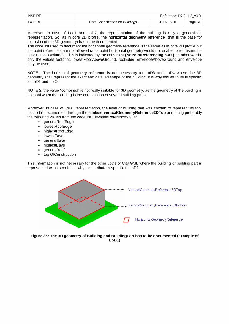
INSPIRE Reference: D2.8.III.2_v3.0
TWG-BU Data Specification on Buildings 2013-12-10 Page 61
Moreover, in case of Lod1 and LoD2, the representation of the building is only a generalised representation. So, as in core 2D profile, the horizontal geometry reference (that is the base for extrusion of the 3D geometry) has to be documented The code list used to document the horizontal geometry reference is the same as in core 2D profile but the point references are not allowed (as a point horizontal geometry would not enable to represent the building as a volume). This is indicated by the constraint {NoPointReferencingIn3D }. In other words, only the values footprint, lowestFloorAboveGround, roofEdge, envelopeAboveGround and envelope may be used. NOTE1: The horizontal geometry reference is not necessary for LoD3 and LoD4 where the 3D geometry shall represent the exact and detailed shape of the building. It is why this attribute is specific to LoD1 and LoD2. NOTE 2: the value ―combined‖ is not really suitable for 3D geometry, as the geometry of the building is optional when the building is the combination of several building parts. Moreover, in case of LoD1 representation, the level of building that was chosen to represent its top, has to be documented, through the attribute verticalGeometryReference3DTop and using preferably the following values from the code list ElevationReferenceValue:
generalRoofEdge
lowestRoofEdge
highestRoofEdge
lowestEave
generalEave
highestEave
generalRoof
top OfConstruction This information is not necessary for the other LoDs of City GML where the building or building part is represented with its roof. It is why this attribute is specific to LoD1.
Figure 35: The 3D geometry of Building and BuildingPart has to be documented (example of LoD1)
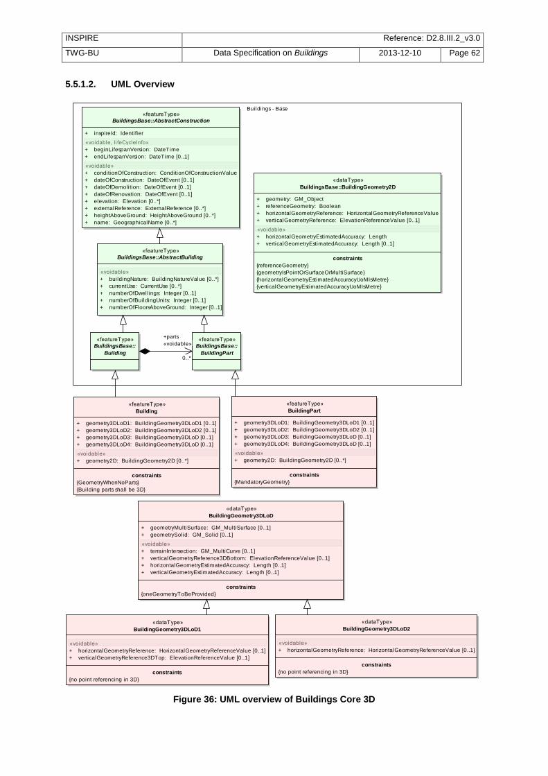
INSPIRE Reference: D2.8.III.2_v3.0
TWG-BU Data Specification on Buildings 2013-12-10 Page 62
5.5.1.2. UML Overview
class Buildings - Core 3D
«featureType»
BuildingsBase::AbstractBuilding
«voidable»
+ buildingNature: BuildingNatureValue [0..*]
+ currentUse: CurrentUse [0..*]
+ numberOfDwellings: Integer [0..1]
+ numberOfBuildingUnits: Integer [0..1]
+ numberOfFloorsAboveGround: Integer [0..1]
«dataType»
BuildingsBase::BuildingGeometry2D
+ geometry: GM_Object
+ referenceGeometry: Boolean
+ horizontalGeometryReference: HorizontalGeometryReferenceValue
+ verticalGeometryReference: ElevationReferenceValue [0..1]
«voidable»
+ horizontalGeometryEstimatedAccuracy: Length
+ verticalGeometryEstimatedAccuracy: Length [0..1]
constraints
{referenceGeometry}
{geometryIsPointOrSurfaceOrMultiSurface}
{horizontalGeometryEstimatedAccuracyUoMIsMetre}
{verticalGeometryEstimatedAccuracyUoMIsMetre}
«featureType»
BuildingsBase::AbstractConstruction
+ inspireId: Identifier
«voidable, l ifeCycleInfo»
+ beginLifespanVersion: DateTime
+ endLifespanVersion: DateTime [0..1]
«voidable»
+ conditionOfConstruction: ConditionOfConstructionValue
+ dateOfConstruction: DateOfEvent [0..1]
+ dateOfDemolition: DateOfEvent [0..1]
+ dateOfRenovation: DateOfEvent [0..1]
+ elevation: Elevation [0..*]
+ externalReference: ExternalReference [0..*]
+ heightAboveGround: HeightAboveGround [0..*]
+ name: GeographicalName [0..*]
Buildings - Base
«featureType»
Building
+ geometry3DLoD1: BuildingGeometry3DLoD1 [0..1]
+ geometry3DLoD2: BuildingGeometry3DLoD2 [0..1]
+ geometry3DLoD3: BuildingGeometry3DLoD [0..1]
+ geometry3DLoD4: BuildingGeometry3DLoD [0..1]
«voidable»
+ geometry2D: BuildingGeometry2D [0..*]
constraints
{GeometryWhenNoParts}
{Building parts shall be 3D}
«featureType»
BuildingPart
+ geometry3DLoD1: BuildingGeometry3DLoD1 [0..1]
+ geometry3DLoD2: BuildingGeometry3DLoD2 [0..1]
+ geometry3DLoD3: BuildingGeometry3DLoD [0..1]
+ geometry3DLoD4: BuildingGeometry3DLoD [0..1]
«voidable»
+ geometry2D: BuildingGeometry2D [0..*]
constraints
{MandatoryGeometry}
«dataType»
BuildingGeometry3DLoD1
«voidable»
+ horizontalGeometryReference: HorizontalGeometryReferenceValue [0..1]
+ verticalGeometryReference3DTop: ElevationReferenceValue [0..1]
constraints
{no point referencing in 3D}
«dataType»
BuildingGeometry3DLoD
+ geometryMultiSurface: GM_MultiSurface [0..1]
+ geometrySolid: GM_Solid [0..1]
«voidable»
+ terrainIntersection: GM_MultiCurve [0..1]
+ verticalGeometryReference3DBottom: ElevationReferenceValue [0..1]
+ horizontalGeometryEstimatedAccuracy: Length [0..1]
+ verticalGeometryEstimatedAccuracy: Length [0..1]
constraints
{oneGeometryToBeProvided}
«dataType»
BuildingGeometry3DLoD2
«voidable»
+ horizontalGeometryReference: HorizontalGeometryReferenceValue [0..1]
constraints
{no point referencing in 3D}
«featureType»
BuildingsBase::
Building
«featureType»
BuildingsBase::
BuildingPart
+parts
«voidable»
0..*
Figure 36: UML overview of Buildings Core 3D

INSPIRE Reference: D2.8.III.2_v3.0
TWG-BU Data Specification on Buildings 2013-12-10 Page 63
5.5.1.3. Consistency between spatial data sets It will be meaningful to use Buidings 3D data (when available) with INSPIRE themes taking also into account the vertical dimension, such as theme Elevation.
5.5.1.4. Modelling of object references The external reference may be used as in core 2D profile. Moreover, in case the 2D (or 2,5D) representation of the building used to construct the 3D representation is not in the same data set as the 3D representation, the external reference may be used to link the spatial object in 3D data base to the 2D object representing the same building. EXAMPLE: a local government has produced 3D data of buildings, using the 2D geometry provided by the national Cadastre. The external reference to the national cadastral system would enable users to know that these two related spatial objects represent the same real world building and would facilitate consistency between these various views on buildings.
5.5.1.5. Geometry representation Art. 12(1) of Regulation 1089/2010 restricts the value domain of spatial properties to the Simple Feature spatial schema as defined in the OpenGIS® Implementation Standard for Geographic information – Simple feature access – Part 1: Common architecture, version 1.2.1, unless specified otherwise for a specific spatial data theme or type.
IR Requirement Section 2.4
Theme-specific Requirement By way of derogation from article 12(1), the value domain of spatial properties used in the Buildings
3D package shall not be restricted.
NOTE2: The topological relations of two spatial objects based on their specific geometry and topology properties can in principle be investigated by invoking the operations of the types defined in ISO 19107 (or the methods specified in EN ISO 19125-1).
Recommendation 11 There should not be penetration between buildings and/or building parts having same temporal validity.
NOTE: buildings and/or building parts may be touching (e.g. through common wall) but should not share common volume.
5.5.2 Feature catalogue
Feature catalogue metadata
Application Schema INSPIRE Application Schema Buildings3D
Version number 3.0
Types defined in the feature catalogue
Type Package Stereotypes
Building Buildings3D «featureType»
BuildingGeometry3DLoD Buildings3D «dataType»
BuildingGeometry3DLoD1 Buildings3D «dataType»
BuildingGeometry3DLoD2 Buildings3D «dataType»

INSPIRE Reference: D2.8.III.2_v3.0
TWG-BU Data Specification on Buildings 2013-12-10 Page 64
Type Package Stereotypes
BuildingPart Buildings3D «featureType»
5.5.2.1. Spatial object types
5.5.2.1.1. Building
Building
Name: Building Subtype of: Building Definition: A Building is an enclosed construction above and/or underground, used or
intended for the shelter of humans, animals or things or for the production of economic goods. A building refers to any structure permanently constructed or erected on its site.
Stereotypes: «featureType»
Attribute: geometry2D
Name: geometry 2D Value type: BuildingGeometry2D Definition: <font color="#0f0f0f">2D or 2.5D geometric representation. <font
color="#0f0f0f"> <font color="#0f0f0f"> Description:
<font color="#0f0f0f">NOTE: Multiple representations of the geometry are possible (e.g. by surface and by point).
Multiplicity: 0..* Stereotypes: «voidable»
Attribute: geometry3DLoD1
Name: geometry 3D LoD 1 Value type: BuildingGeometry3DLoD1 Definition: 3D geometric representation at level of detail (LoD) 1, consisting of the
generalized representation of the outer boundary by vertical lateral surfaces and horizontal base polygons.
Multiplicity: 0..1
Attribute: geometry3DLoD2
Name: geometry 3D LoD 2 Value type: BuildingGeometry3DLoD2 Definition: 3D geometric representation at level of detail (LoD) 2, consisting of the
generalized representation of the outer boundary by vertical lateral surfaces and a prototypical roof shape or cover (from a defined list of roof shapes)
Description: NOTE: The prototypical roof shapes come from a defined list of roof shapes, in City GML; this list is equivalent to the code list RoofTypeValue, provided in the extended2D profile (without the hyperbolic parabaloidal roof).
Multiplicity: 0..1
Attribute: geometry3DLoD3
Name: geometry 3D LoD 3 Value type: BuildingGeometry3DLoD Definition: 3D geometric representation at level of detail (LoD) 3, consisting of the detailed
representation of the outer boundary (including protrusions, facade elements and window recesses) as well as of the roof shape (including dormers, chimneys).
Multiplicity: 0..1
Attribute: geometry3DLoD4
Name: geometry 3D LoD 4 Value type: BuildingGeometry3DLoD
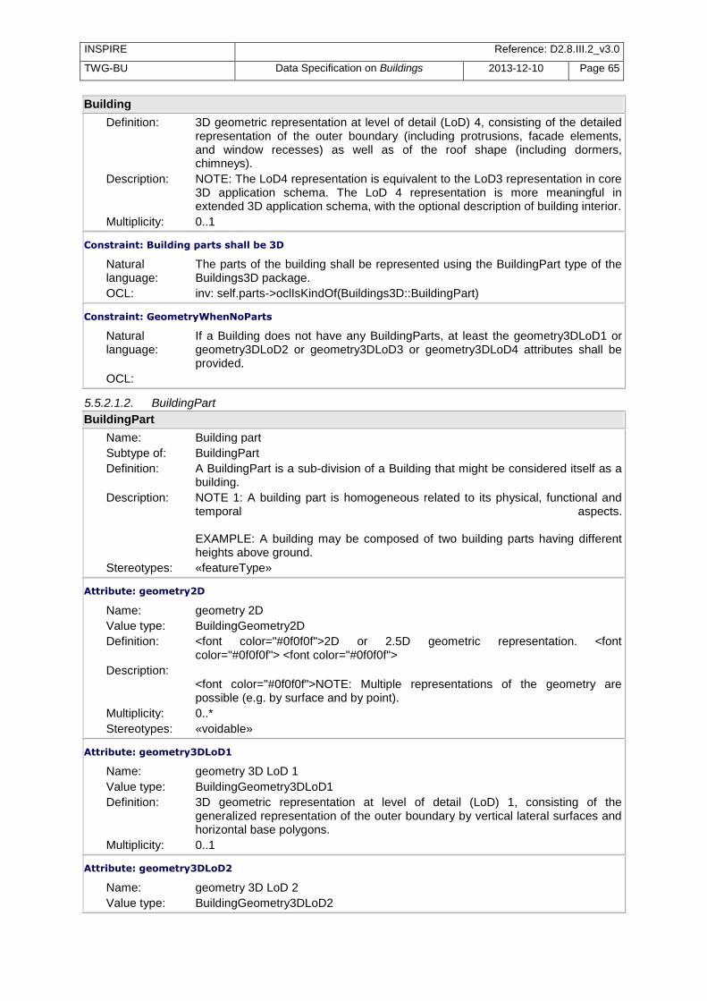
INSPIRE Reference: D2.8.III.2_v3.0
TWG-BU Data Specification on Buildings 2013-12-10 Page 65
Building
Definition: 3D geometric representation at level of detail (LoD) 4, consisting of the detailed representation of the outer boundary (including protrusions, facade elements, and window recesses) as well as of the roof shape (including dormers, chimneys).
Description: NOTE: The LoD4 representation is equivalent to the LoD3 representation in core 3D application schema. The LoD 4 representation is more meaningful in extended 3D application schema, with the optional description of building interior.
Multiplicity: 0..1
Constraint: Building parts shall be 3D
Natural language:
The parts of the building shall be represented using the BuildingPart type of the Buildings3D package.
OCL: inv: self.parts->oclIsKindOf(Buildings3D::BuildingPart)
Constraint: GeometryWhenNoParts
Natural language:
If a Building does not have any BuildingParts, at least the geometry3DLoD1 or geometry3DLoD2 or geometry3DLoD3 or geometry3DLoD4 attributes shall be provided.
OCL:
5.5.2.1.2. BuildingPart
BuildingPart
Name: Building part Subtype of: BuildingPart Definition: A BuildingPart is a sub-division of a Building that might be considered itself as a
building. Description: NOTE 1: A building part is homogeneous related to its physical, functional and
temporal aspects. EXAMPLE: A building may be composed of two building parts having different heights above ground.
Stereotypes: «featureType»
Attribute: geometry2D
Name: geometry 2D Value type: BuildingGeometry2D Definition: <font color="#0f0f0f">2D or 2.5D geometric representation. <font
color="#0f0f0f"> <font color="#0f0f0f"> Description:
<font color="#0f0f0f">NOTE: Multiple representations of the geometry are possible (e.g. by surface and by point).
Multiplicity: 0..* Stereotypes: «voidable»
Attribute: geometry3DLoD1
Name: geometry 3D LoD 1 Value type: BuildingGeometry3DLoD1 Definition: 3D geometric representation at level of detail (LoD) 1, consisting of the
generalized representation of the outer boundary by vertical lateral surfaces and horizontal base polygons.
Multiplicity: 0..1
Attribute: geometry3DLoD2
Name: geometry 3D LoD 2 Value type: BuildingGeometry3DLoD2

INSPIRE Reference: D2.8.III.2_v3.0
TWG-BU Data Specification on Buildings 2013-12-10 Page 66
BuildingPart
Definition: 3D geometric representation at level of detail (LoD) 2, consisting of the generalized representation of the outer boundary by vertical lateral surfaces and a prototypical roof shape or cover (from a defined list of roof shapes). NOTE: The prototypical roof shapes come from a defined list of roof shapes, in City GML; this list is equivalent to the code list RoofTypeValue, provided in the extended2D profile (without the hyperbolic parabaloidal roof).
Multiplicity: 0..1
Attribute: geometry3DLoD3
Name: geometry 3D LoD 3 Value type: BuildingGeometry3DLoD Definition: 3D geometric representation at level of detail (LoD) 3, consisting of the detailed
representation of the outer boundary (including protrusions, facade elements and window recesses) as well as of the roof shape (including dormers, chimneys).
Multiplicity: 0..1
Attribute: geometry3DLoD4
Name: geometry 3D LoD 4 Value type: BuildingGeometry3DLoD Definition: 3D geometric representation at level of detail (LoD) 4, consisting of the detailed
representation of the outer boundary (including protrusions, facade elements, and window recesses) as well as of the roof shape (including dormers, chimneys).
Description: NOTE: The LoD4 representation is equivalent to the LoD3 representation in core 3D application schema. The LoD 4 representation is more meaningful in extended 3D application schema, with the optional description of building interior.
Multiplicity: 0..1
Constraint: MandatoryGeometry
Natural language:
At least one of the geometry3DLoD1 or geometry3DLoD2 or geometry3DLoD3 or geometry3DLoD4 attributes shall be provided.
OCL:
5.5.2.2. Data types
5.5.2.2.1. BuildingGeometry3DLoD
BuildingGeometry3DLoD
Name: Building geometry 3D LoD Definition: Data type grouping the 3D geometry of a building or building part and the
metadata information attached to this geometry. Stereotypes: «dataType»
Attribute: geometryMultiSurface
Name: Geometry multi-surface Value type: GM_MultiSurface Definition: Representation of the outer boundary by a Multi Surface, which may - in contrast
to a solid representation - not be topologically clean. In particular, the ground surface may be missing.
Multiplicity: 0..1
Attribute: geometrySolid
Name: Geometry solid Value type: GM_Solid Definition: Representation of the outer boundary by a solid. Multiplicity: 0..1

INSPIRE Reference: D2.8.III.2_v3.0
TWG-BU Data Specification on Buildings 2013-12-10 Page 67
BuildingGeometry3DLoD
Attribute: terrainIntersection
Name: Terrain intersection Value type: GM_MultiCurve Definition: Line or multi-line where the spatial object (Building, BuildingPart, ...) touches the
terrain representation. Multiplicity: 0..1 Stereotypes: «voidable»
Attribute: verticalGeometryReference3DBottom
Name: Vertical geometry reference 3D bottom Value type: ElevationReferenceValue Definition: Height level to which the lower height of the model (Z-value of the lower
horizontal polygon) refers to. Description: EXAMPLE: generalGround, bottomOfConstruction. Multiplicity: 0..1 Stereotypes: «voidable»
Attribute: horizontalGeometryEstimatedAccuracy
Name: Horizontal geometry estimated accuracy Value type: Length Definition: The estimated absolute positional accuracy of the (X,Y) coordinates of the
geometry, in the INSPIRE official Coordinate Reference System. Absolute positional accuracy is defined as the mean value of the positional uncertainties for a set of positions where the positional uncertainties are defined as the distance between a measured position and what is considered as the corresponding true position.
Description: NOTE: this mean value may come from quality measures on a homogeneous population of buildings or from an estimation based on the knowledge of the production processes and of their accuracy.
Multiplicity: 0..1 Stereotypes: «voidable»
Attribute: verticalGeometryEstimatedAccuracy
Name: Vertical geometry estimated accuracy Value type: Length Definition: The estimated absolute positional accuracy of the Z- coordinate of the geometry,
in the INSPIRE official Coordinate Reference System. Absolute positional accuracy is defined as the mean value of the positional uncertainties for a set of positions where the positional uncertainties are defined as the distance between a measured position and what is considered as the corresponding true position.
Description: NOTE: this mean value may come from quality measures on a homogeneous population of buildings or from an estimation based on the knowledge of the production processes and of their accuracy.
Multiplicity: 0..1 Stereotypes: «voidable»
Constraint: oneGeometryToBeProvided
Natural language:
Either the geometryMultiSurface or the geometrySolid attribute shall be provided.
OCL: inv: self.geometryMultiSurface->notEmpty() or self.geometrySolid->notEmpty()
5.5.2.2.2. BuildingGeometry3DLoD1
BuildingGeometry3DLoD1
Name: Building geometry 3D LoD 1

INSPIRE Reference: D2.8.III.2_v3.0
TWG-BU Data Specification on Buildings 2013-12-10 Page 68
BuildingGeometry3DLoD1
Subtype of: BuildingGeometry3DLoD Definition: Data type grouping the specific metadata attached to the 3D geometry, when
provided by a LoD 1 representation. Stereotypes: «dataType»
Attribute: horizontalGeometryReference
Name: Horizontal geometry reference Value type: HorizontalGeometryReferenceValue Definition: Element of the real world object that was captured by the (X,Y) coordinates of
the LoD1 Multisurface or Solid geometry. Description: EXAMPLE: footprint, roof edge Multiplicity: 0..1 Stereotypes: «voidable»
Attribute: verticalGeometryReference3DTop
Name: Vertical geometry reference 3D top Value type: ElevationReferenceValue Definition: Height level to which the upper height of the model (Z-value of the upper
horizontal polygon) refers to. Description: EXAMPLE: generalRoof, lowestRoof Edge. Multiplicity: 0..1 Stereotypes: «voidable»
Constraint: no point referencing in 3D
Natural language:
The horizontalGeometryReference attribute shall not take the value entrancePoint, pointInsideBuilding or pointInsideCadastralParcel.
OCL: inv: self.horizontalGeometryReference->excludesAll(Set{HorizontalGeometryReferenceValue::entrancePoint, HorizontalGeometryReferenceValue::pointInsideBuilding , HorizontalGeometryReferenceValue::pointInsideCadastralParcel})
5.5.2.2.3. BuildingGeometry3DLoD2
BuildingGeometry3DLoD2
Name: Building geometry 3D LoD 2 Subtype of: BuildingGeometry3DLoD Definition: Data type grouping the specific metadata attached to the 3D geometry, when
provided by a LoD2 representation. Stereotypes: «dataType»
Attribute: horizontalGeometryReference
Name: Horizontal geometry reference Value type: HorizontalGeometryReferenceValue Definition: Element that was captured by the (X,Y) coordinates of the LoD2 MultiSurface or
Solid geometry. Description: EXAMPLE: footprint, roof edge Multiplicity: 0..1 Stereotypes: «voidable»
Constraint: no point referencing in 3D
Natural language:
The horizontalGeometryReference attribute shall not take the value entrancePoint, pointInsideBuilding or pointInsideCadastralParcel.
OCL: inv: self.horizontalGeometryReference->excludesAll(Set{HorizontalGeometryReferenceValue::entrancePoint, HorizontalGeometryReferenceValue::pointInsideBuilding ,
INSPIRE Reference: D2.8.III.2_v3.0
TWG-BU Data Specification on Buildings 2013-12-10 Page 69
BuildingGeometry3DLoD2
HorizontalGeometryReferenceValue::pointInsideCadastralParcel})
5.5.2.3. Imported types (informative)
This section lists definitions for feature types, data types and enumerations and code lists that are defined in other application schemas. The section is purely informative and should help the reader understand the feature catalogue presented in the previous sections. For the normative documentation of these types, see the given references.
5.5.2.3.1. BuildingGeometry2D
BuildingGeometry2D
Package: BuildingsBase Reference: INSPIRE Data specification on Buildings [DS-D2.8.III.2] Definition: This data types includes the geometry of the building and metadata information
about which element of the building was captured and how.
5.5.2.3.2. ElevationReferenceValue
ElevationReferenceValue
Package: BuildingsBase Reference: INSPIRE Data specification on Buildings [DS-D2.8.III.2] Definition: List of possible elements considered to capture a vertical geometry. Description: NOTE: The values of this code list are used to describe the reference of
elevation both where elevation has been captured as attribute or as Z coordinate.
5.5.2.3.3. GM_MultiCurve
GM_MultiCurve
Package: Geometric aggregates Reference: Geographic information -- Spatial schema [ISO 19107:2003]
5.5.2.3.4. GM_MultiSurface
GM_MultiSurface
Package: Geometric aggregates Reference: Geographic information -- Spatial schema [ISO 19107:2003]
5.5.2.3.5. GM_Solid
GM_Solid
Package: Geometric primitive Reference: Geographic information -- Spatial schema [ISO 19107:2003]
5.5.2.3.6. HorizontalGeometryReferenceValue
HorizontalGeometryReferenceValue
Package: BuildingsBase Reference: INSPIRE Data specification on Buildings [DS-D2.8.III.2] Definition: Values indicating the element considered to capture a horizontal geometry.
5.5.2.3.7. Length
Length
Package: Units of Measure Reference: Geographic information -- Conceptual schema language [ISO/TS 19103:2005]
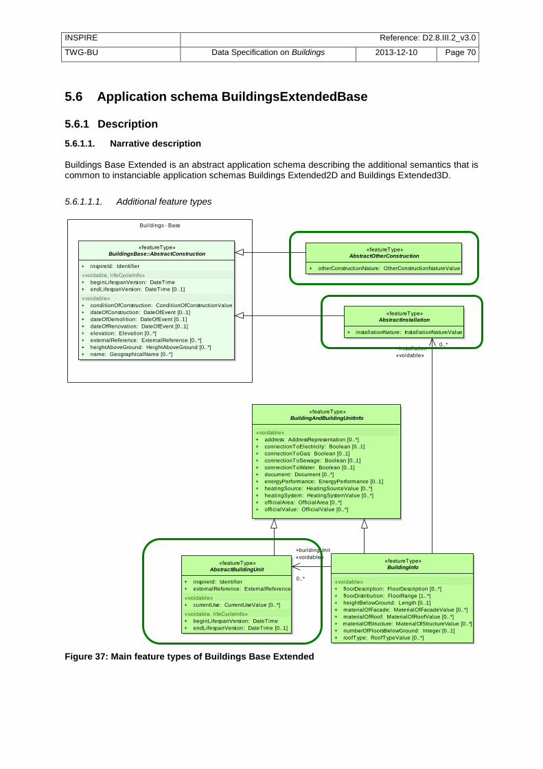
INSPIRE Reference: D2.8.III.2_v3.0
TWG-BU Data Specification on Buildings 2013-12-10 Page 70
5.6 Application schema BuildingsExtendedBase
5.6.1 Description
5.6.1.1. Narrative description Buildings Base Extended is an abstract application schema describing the additional semantics that is common to instanciable application schemas Buildings Extended2D and Buildings Extended3D.
5.6.1.1.1. Additional feature types
class BuildingsExtendedBase
«featureType»
BuildingsBase::AbstractConstruction
+ inspireId: Identifier
«voidable, l ifeCycleInfo»
+ beginLifespanVersion: DateTime
+ endLifespanVersion: DateTime [0..1]
«voidable»
+ conditionOfConstruction: ConditionOfConstructionValue
+ dateOfConstruction: DateOfEvent [0..1]
+ dateOfDemolition: DateOfEvent [0..1]
+ dateOfRenovation: DateOfEvent [0..1]
+ elevation: Elevation [0..*]
+ externalReference: ExternalReference [0..*]
+ heightAboveGround: HeightAboveGround [0..*]
+ name: GeographicalName [0..*]
«featureType»
BuildingInfo
«voidable»
+ floorDescription: FloorDescription [0..*]
+ floorDistribution: FloorRange [1..*]
+ heightBelowGround: Length [0..1]
+ materialOfFacade: MaterialOfFacadeValue [0..*]
+ materialOfRoof: MaterialOfRoofValue [0..*]
+ materialOfStructure: MaterialOfStructureValue [0..*]
+ numberOfFloorsBelowGround: Integer [0..1]
+ roofType: RoofTypeValue [0..*]
«featureType»
AbstractBuildingUnit
+ inspireId: Identifier
+ externalReference: ExternalReference
«voidable»
+ currentUse: CurrentUseValue [0..*]
«voidable, l ifeCycleInfo»
+ beginLifespanVersion: DateTime
+ endLifespanVersion: DateTime [0..1]
«featureType»
AbstractOtherConstruction
+ otherConstructionNature: OtherConstructionNatureValue
«featureType»
AbstractInstallation
+ installationNature: InstallationNatureValue
Buildings - Base
«featureType»
BuildingAndBuildingUnitInfo
«voidable»
+ address: AddressRepresentation [0..*]
+ connectionToElectricity: Boolean [0..1]
+ connectionToGas: Boolean [0..1]
+ connectionToSewage: Boolean [0..1]
+ connectionToWater: Boolean [0..1]
+ document: Document [0..*]
+ energyPerformance: EnergyPerformance [0..1]
+ heatingSource: HeatingSourceValue [0..*]
+ heatingSystem: HeatingSystemValue [0..*]
+ officialArea: OfficialArea [0..*]
+ officialValue: OfficialValue [0..*]
+buildingUnit
«voidable»
0..*
+installation
«voidable»
0..*
Figure 37: Main feature types of Buildings Base Extended

INSPIRE Reference: D2.8.III.2_v3.0
TWG-BU Data Specification on Buildings 2013-12-10 Page 71
The Buildings BaseExtended contains mainly 3 new feature types:
OtherConstructions are self-standing constructions that are generally not considered as buildings. This extended profile includes the most significant constructions that are necessary to describe landscape and to fulfil use cases such as safety or spatial planning.
Installations are constructions, generally of small size that are attached to a Building (or a BuildingPart).
BuildingUnits are subdivisions of Building with their own lockable access from the outside or from a common area (i.e. not from another BuildingUnit), which are atomic, functionally independent, and may be separately sold, rented out, inherited, etc.
A building unit is homogeneous for management aspects. Its key mandatory attribute is the external reference to some official register where the BuildingUnit is identified and described. It is generally the cadastral register but may be another information system, e.g. a register of public properties.
5.6.1.1.2. Other Constructions Other constructions inherit of the attributes of AbstractConstruction (from <BuildingsBase> ) and are mainly described by their nature, that may take following values:
acousticFence antenna chimney bridge bridge
cityWall crane monument monument monument
monument monument openAirPool protectiveStructure protectiveStructure
pylon retainingWall solarPanel substation tunnel
Figure 38: Illustrations of other constructions

INSPIRE Reference: D2.8.III.2_v3.0
TWG-BU Data Specification on Buildings 2013-12-10 Page 72
5.6.1.1.3. Installations Installations inherit of the attributes of AbstractConstruction (from <BuildingsBase> ) and are mainly described by their nature, that may take the following values.
airConditioningUnit airDuct antenna antenna arcade
balcony chimney chimney cradle dormer
externalLift railing ramp solarPanel stairway
stairway stairway tower windTurbine windTurbine
Figure 39: Illustrations for of installation nature
NOTE 1: The list of installation nature does not aim to be exhaustive but focus on the installations related to safety and on environmental issues (mainly energy). NOTE 2: The code list for installation nature is the same for extended 2D and extended 3D data. However, likely, some values will be used only for 3D data (e.g. dormer, arcade, balcony).
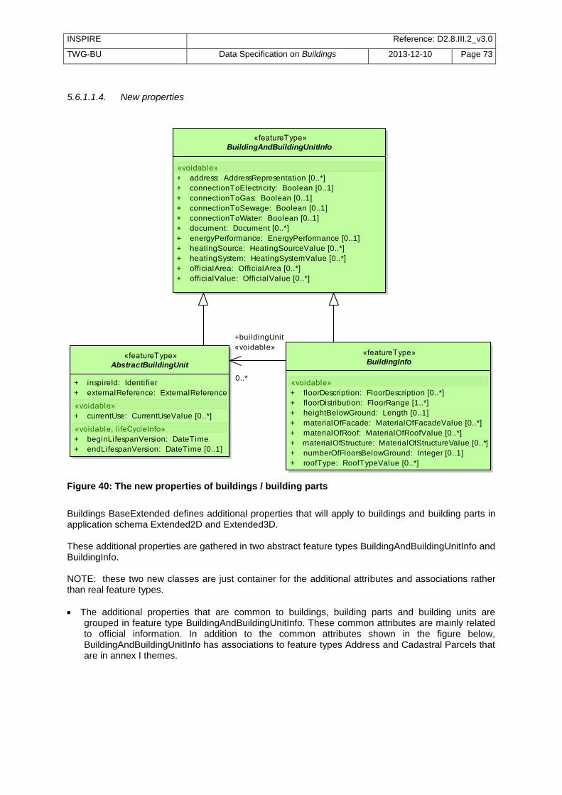
INSPIRE Reference: D2.8.III.2_v3.0
TWG-BU Data Specification on Buildings 2013-12-10 Page 73
5.6.1.1.4. New properties
class BuildingsExtendedBase
«featureType»
BuildingInfo
«voidable»
+ floorDescription: FloorDescription [0..*]
+ floorDistribution: FloorRange [1..*]
+ heightBelowGround: Length [0..1]
+ materialOfFacade: MaterialOfFacadeValue [0..*]
+ materialOfRoof: MaterialOfRoofValue [0..*]
+ materialOfStructure: MaterialOfStructureValue [0..*]
+ numberOfFloorsBelowGround: Integer [0..1]
+ roofType: RoofTypeValue [0..*]
«featureType»
AbstractBuildingUnit
+ inspireId: Identifier
+ externalReference: ExternalReference
«voidable»
+ currentUse: CurrentUseValue [0..*]
«voidable, l ifeCycleInfo»
+ beginLifespanVersion: DateTime
+ endLifespanVersion: DateTime [0..1]
«featureType»
BuildingAndBuildingUnitInfo
«voidable»
+ address: AddressRepresentation [0..*]
+ connectionToElectricity: Boolean [0..1]
+ connectionToGas: Boolean [0..1]
+ connectionToSewage: Boolean [0..1]
+ connectionToWater: Boolean [0..1]
+ document: Document [0..*]
+ energyPerformance: EnergyPerformance [0..1]
+ heatingSource: HeatingSourceValue [0..*]
+ heatingSystem: HeatingSystemValue [0..*]
+ officialArea: OfficialArea [0..*]
+ officialValue: OfficialValue [0..*]
+buildingUnit
«voidable»
0..*
Figure 40: The new properties of buildings / building parts
Buildings BaseExtended defines additional properties that will apply to buildings and building parts in application schema Extended2D and Extended3D. These additional properties are gathered in two abstract feature types BuildingAndBuildingUnitInfo and BuildingInfo. NOTE: these two new classes are just container for the additional attributes and associations rather than real feature types.
The additional properties that are common to buildings, building parts and building units are grouped in feature type BuildingAndBuildingUnitInfo. These common attributes are mainly related to official information. In addition to the common attributes shown in the figure below, BuildingAndBuildingUnitInfo has associations to feature types Address and Cadastral Parcels that are in annex I themes.

INSPIRE Reference: D2.8.III.2_v3.0
TWG-BU Data Specification on Buildings 2013-12-10 Page 74
class BuildingsExtendedBase
«featureType»
BuildingAndBuildingUnitInfo
«voidable»
+ connectionToElectricity: Boolean [0..1]
+ connectionToGas: Boolean [0..1]
+ connectionToSewage: Boolean [0..1]
+ connectionToWater: Boolean [0..1]
+ document: Document [0..*]
+ energyPerformance: EnergyPerformance [0..1]
+ heatingSource: HeatingSourceValue [0..*]
+ heatingSystem: HeatingSystemValue [0..*]
+ address: AddressRepresentation [0..*]
+ officialArea: OfficialArea [0..*]
+ officialValue: OfficialValue [0..*]
Figure 41: Common additional attributes of buildings, building parts and building units
The additional properties that are specific to buildings and building parts are grouped in feature type BuildingInfo. These attributes address the physical description with more details than in the <Buildings Base> application schema.
class BuildingsExtendedBase
«featureType»
BuildingInfo
«voidable»
+ heightBelowGround: Length [0..1]
+ numberOfFloorsBelowGround: Integer [0..1]
+ floorDistribution: FloorRange [1..*]
+ floorDescription: FloorDescription [0..*]
+ roofType: RoofTypeValue [0..*]
+ materialOfFacade: MaterialOfFacadeValue [0..*]
+ materialOfRoof: MaterialOfRoofValue [0..*]
+ materialOfStructure: MaterialOfStructureValue [0..*]
Figure 42: Common additional attributes to buildings and building parts
5.6.1.1.5. Attribute roofType This attribute may take the following values:
flatRoof monopitchRoof gabledRoof hippedRoof MansardRoof
Official information
Information about heating / energy
Connection to netwoks
Underground description
Materials

INSPIRE Reference: D2.8.III.2_v3.0
TWG-BU Data Specification on Buildings 2013-12-10 Page 75
halfHippedRoof coneRoof pyramidalBroachRoof copulaRoof
archRoof dualPentRoof sawToothRoof
pavilionRoof hyperbolicParabaloidalRoof
Figure 43: Roof types (most illustrations from 3D GIS)
5.6.1.1.6. Attribute MaterialOfStructure This attribute may take the following values:
adobeBlockWalls concreteBlockMasonry earth firedBrickMasonry
informalConstructions massiveStoneMasonry mobileHomes mudWalls

INSPIRE Reference: D2.8.III.2_v3.0
TWG-BU Data Specification on Buildings 2013-12-10 Page 76
precastConcrete Tilt-upWalls
reinforcedConcrete reinforcedMasonry rubleStoneMasonry
steel stoneMasonryBlock wood wood
Figure 44: Illustrations for material of structure
5.6.1.1.7. MaterialOfFacade
This attribute may take the following values:
adobe asbestos ceramicTiles composite
concrete glass limestone masonry
metal naturalStone vegetated wood
Figure 45: Illustrations for material of facade

INSPIRE Reference: D2.8.III.2_v3.0
TWG-BU Data Specification on Buildings 2013-12-10 Page 77
5.6.1.1.8. MaterialOfRoof
This attribute may take the following values:
asbestos ceramicTiles clayTile composition
concreteTile corrugatedSheet glass hotMoppedAsphalt
metal reinforcedConcrete slate slate
thatch thatch vegetatedRoof woodShingles
OrShakes
Figure 46: Illustrations for material of roof
5.6.1.1.9. Attribute Document The INSPIRE model allows the possibility to link documents to a building or a building part or a floor or a building unit; various documents may be concerned, such as images, sketches, building permits, emergency plans ….. . The attribute Document is defined as a data type with the link to the place the document may be found and with a simple set of metadata elements.

INSPIRE Reference: D2.8.III.2_v3.0
TWG-BU Data Specification on Buildings 2013-12-10 Page 78
class BuildingsExtendedBase - DataTypes
«dataType»
Document
+ documentLink: URI
«voidable»
+ date: DateTime [0..1]
+ documentDescription: PT_FreeText [0..1]
+ sourceStatus: SourceStatusValue
«codeList»
SourceStatusValueOfficial
Non-official
Figure 47: The data type Document
Recommendation 1 Documents should be provided in well-known and easy to handle formats.
EXAMPLE: documents may be provided in .PDF, .TIF (or geotif), .JPEG, .BMP, .PNG. NOTE 1: Formats whose content is unknown to user, such as .EXE or .ZIP should be avoided. NOTE 2: The documents related to the regulations that apply on all buildings in an area of interest (e.g. land use zone, regulated area, protected site) may and should rather be provided in the respective other INSPIRE themes.
5.6.1.1.10. Attribute officialValue The attribute official value may be submitted to access restrictions due for instance to privacy issues. Consequently, the INSPIRE model allows this information to be provided, either directly by its value and currency or indirectly by the external reference to another information system. In first case, the access to the information of official area is widely open, following INSPIRE rules. In the second case, the access to the other external information system may be restricted to authorized users. In addition to the official value itself, some metadata elements should be provided in order to indicate what the official value represents.
class BuildingsExtendedBase - DataTypes
«dataType»
OfficialValue
«voidable»
+ currency: CurrencyValue
+ value: Integer
+ valuationDate: DateTime
+ officialValueReference: OfficialValueReferenceValue
+ referencePercentage: Integer
+ informationSystemName: PT_FreeText
Figure 48: The data type OfficialValue
Metadata information
Value is provided directly
Value is provided indirectly

INSPIRE Reference: D2.8.III.2_v3.0
TWG-BU Data Specification on Buildings 2013-12-10 Page 79
class BuildingsExtendedBase - DataTypes
«dataType»
OfficialValue
«voidable»
+ currency: CurrencyValue
+ value: Integer
+ valuationDate: DateTime
+ officialValueReference: OfficialValueReferenceValue
+ referencePercentage: Integer
+ informationSystemName: PT_FreeText
constraints
{either value and currency or informationSystemName shall be provided}
{informationSystemName shall be present in one external reference}
class Buildings - Base: Data Types
«dataType»
ExternalReference
+ informationSystem: URI
+ informationSystemName: PT_FreeText
+ reference: CharacterString
Figure 49: The mechanism to get official value through external reference to another information
NOTE: The mechanism to provide value of an attribute either directly or through the reference to another information system may be used by data providers for other attributes, in case they are submitted to access restrictions.

INSPIRE Reference: D2.8.III.2_v3.0
TWG-BU Data Specification on Buildings 2013-12-10 Page 80
5.6.1.2. UML Overview
class BuildingsExtendedBase
Cadastral parcels
«featureType»
BuildingsBase::AbstractConstruction
+ inspireId: Identifier
«voidable, l ifeCycleInfo»
+ beginLifespanVersion: DateTime
+ endLifespanVersion: DateTime [0..1]
«voidable»
+ conditionOfConstruction: ConditionOfConstructionValue
+ dateOfConstruction: DateOfEvent [0..1]
+ dateOfDemolition: DateOfEvent [0..1]
+ dateOfRenovation: DateOfEvent [0..1]
+ elevation: Elevation [0..*]
+ externalReference: ExternalReference [0..*]
+ heightAboveGround: HeightAboveGround [0..*]
+ name: GeographicalName [0..*]
«featureType»
BuildingInfo
«voidable»
+ heightBelowGround: Length [0..1]
+ numberOfFloorsBelowGround: Integer [0..1]
+ floorDistribution: FloorRange [1..*]
+ floorDescription: FloorDescription [0..*]
+ roofType: RoofTypeValue [0..*]
+ materialOfFacade: MaterialOfFacadeValue [0..*]
+ materialOfRoof: MaterialOfRoofValue [0..*]
+ materialOfStructure: MaterialOfStructureValue [0..*]
«featureType»
AbstractBuildingUnit
+ inspireId: Identifier
+ externalReference: ExternalReference
«voidable»
+ currentUse: CurrentUseValue [0..*]
«voidable, l ifeCycleInfo»
+ beginLifespanVersion: DateTime
+ endLifespanVersion: DateTime [0..1]
«featureType»
AbstractOtherConstruction
+ otherConstructionNature: OtherConstructionNatureValue
«featureType»
AbstractInstallation
+ installationNature: InstallationNatureValue
Buildings - Base
Addresses
«featureType»
BuildingAndBuildingUnitInfo
«voidable»
+ connectionToElectricity: Boolean [0..1]
+ connectionToGas: Boolean [0..1]
+ connectionToSewage: Boolean [0..1]
+ connectionToWater: Boolean [0..1]
+ document: Document [0..*]
+ energyPerformance: EnergyPerformance [0..1]
+ heatingSource: HeatingSourceValue [0..*]
+ heatingSystem: HeatingSystemValue [0..*]
+ address: AddressRepresentation [0..*]
+ officialArea: OfficialArea [0..*]
+ officialValue: OfficialValue [0..*]
«dataType»
Addresses::AddressRepresentation
+ adminUnit: GeographicalName [1..*] {ordered}
+ locatorDesignator: CharacterString [0..*] {ordered}
+ locatorName: GeographicalName [0..*] {ordered}
«voidable»
+ addressArea: GeographicalName [0..*] {ordered}
+ postName: GeographicalName [0..*] {ordered}
+ postCode: CharacterString [0..1]
+ thoroughfare: GeographicalName [0..*] {ordered}
«featureType»
CadastralParcels::CadastralParcel
+ geometry: GM_Object
+ inspireId: Identifier
+ label: CharacterString
+ nationalCadastralReference: CharacterString
«voidable»
+ areaValue: Area [0..1]
+ referencePoint: GM_Point [0..1]
+ validFrom: DateTime [0..1]
+ validTo: DateTime [0..1]
«lifeCycleInfo, voidable»
+ beginLifespanVersion: DateTime
+ endLifespanVersion: DateTime [0..1] A
+buildingUnit
«voidable»
0..*
+installation
«voidable»
0..*
+cadastralParcel
«voidable»
0..*
+address
«voidable»
0..*
Figure 50: Overview of BuildingExtendedBase

INSPIRE Reference: D2.8.III.2_v3.0
TWG-BU Data Specification on Buildings 2013-12-10 Page 81
class BuildingsExtendedBase - DataTypes
«dataType»
OfficialArea
+ value: Area
«voidable»
+ officialAreaReference: OfficialAreaReferenceValue
+ heightParameter: Length [0..1] = 2.10 m
«dataType»
EnergyPerformance
+ energyPerformanceValue: EnergyPerformanceValue
«voidable»
+ dateOfAssessment: DateTime
+ assessmentMethod: DocumentCitation
«dataType»
OfficialValue
«voidable»
+ currency: CurrencyValue
+ value: Integer
+ valuationDate: DateTime
+ officialValueReference: OfficialValueReferenceValue
+ referencePercentage: Integer
+ informationSystemName: PT_FreeText
constraints
{either value and currency or informationSystemName shall be provided}
{informationSystemName shall be present in one external reference}
«dataType»
FloorRange
+ lowestFloor: Real
+ highestFloor: Real
«dataType»
FloorDescription
+ floorRange: FloorRange [1..*]
«voidable»
+ areaOfOpenings: Area
+ currentUse: CurrentUseValue [1..*]
+ document: Document [0..*]
+ floorArea: Area
+ height: Length
+ numberOfDwellings: Integer
«dataType»
Document
+ documentLink: URI
«voidable»
+ date: DateTime [0..1]
+ documentDescription: PT_FreeText [0..1]
+ sourceStatus: SourceStatusValue
«codeList»
CLGE_OfficialAreaReferenceValue
tags
extensibil ity = none
vocabulary = http://inspire.ec.europa.eu/codeList/OfficialAreaReferenceValue
«codeList»
OfficialAreaReferenceValue
«codeList»
CurrencyValue
«codeList»
OfficialValueReferenceValue
«codeList»
SourceStatusValue
«codeList»
EnergyPerformanceValue
Official
Non-official
constructedArea, externalArea,
internalArea, internalPrimaryArea,
internalOtherArea, internalResidualArea,
internalServiceArea.
«codeList»
OtherStandardOfficialAreaReferenceValue
tags
extensibil ity = any
vocabulary =
EUR,SEK,MDL,CHF,
ISK,GBP,RUB,RSD
rentalIncome,
transactionPriceFull,
transactionPriceMedium,
transactionPriceSimple
A, B, C, D, E, F, G
{complete
Figure 51: Overview of BuildingExtendedBase - Data Types

INSPIRE Reference: D2.8.III.2_v3.0
TWG-BU Data Specification on Buildings 2013-12-10 Page 82
class BuildingsExtendedBase - other codelists
«codeList»
HeatingSourceValue«codeList»
HeatingSystemValue
«codeList»
InstallationNatureValue
«codeList»
MaterialOfFacadeValue
«codeList»
MaterialOfRoofValue
«codeList»
MaterialOfStructureValue
«codeList»
OtherConstructionNatureValue
«codeList»
RoofTypeValue
airConditioningUnit, airDuct, antenna, arcade,
balcony, chimney, cradle, dormer, externalLift,
rail ing, ramp, solarPanel, stairway, tower,
windTurbine
acousticFence, antenna, bridge, chimney,
cityWall, crane, monument, openAirPool,
protectiveStructure, pylon, retainingWall,
solarPanel, substation, tunnel
archRoof, conicalRoof, domedRoof, dualPentRoof,
flatRoof, gabledRoof, halfHippedRoof, hippedRoof,
hyperbolicParabaloidalRoof, mansardRoof,
monopitchRoof, pavilionRoof,
pyramidalBroachRoof, sawToothRoof
adobe, asbestos,
ceramicTiles, composite,
concrete, glass, l imestone,
masonry, metal,
naturalStone, vegetated,
wood.
asbestos, ceramicTile, clayTile,
composition, concreteTile,
corrugatedSheet, glass, hotMoppedAsphalt,
metal, reinforcedConcrete, slate, thatch,
vegetatedGreenRoof,
woodShinglesOrShakes
adobeBlockWalls, concreteBlockMasonry, earth,
firedBrickMasonry, informalConstructions,
massiveStoneMasonry, mobileHomes, mudWalls,
precastConcrete, reinforcedConcrete,
reinforcedMasonry, rubleStoneMasonry, steel,
stoneMasonryBlock, wood
biogas, electricity, l iquidFuels,
naturalGas, solidFuels, straw,
warmWaterOrStream
centralHeating, districtHeating,
electricRaditors, heatPump,
portableGasHeating, solarHeating, stove
Figure 52: Overview of BuildingExtendedBase - Code lists
5.6.2 Feature catalogue
Feature catalogue metadata
Application Schema INSPIRE Application Schema BuildingsExtendedBase
Version number 3.0
Types defined in the feature catalogue
Type Package Stereotypes
AbstractBuildingUnit BuildingsExtendedBase «featureType»
AbstractInstallation BuildingsExtendedBase «featureType»
AbstractOtherConstruction BuildingsExtendedBase «featureType»
BuildingAndBuildingUnitInfo BuildingsExtendedBase «featureType»
BuildingInfo BuildingsExtendedBase «featureType»
CLGE_OfficialAreaReferenceValue BuildingsExtendedBase «codeList»

INSPIRE Reference: D2.8.III.2_v3.0
TWG-BU Data Specification on Buildings 2013-12-10 Page 83
Type Package Stereotypes
CurrencyValue BuildingsExtendedBase «codeList»
Document BuildingsExtendedBase «dataType»
EnergyPerformance BuildingsExtendedBase «dataType»
EnergyPerformanceValue BuildingsExtendedBase «codeList»
FloorDescription BuildingsExtendedBase «dataType»
FloorRange BuildingsExtendedBase «dataType»
HeatingSourceValue BuildingsExtendedBase «codeList»
HeatingSystemValue BuildingsExtendedBase «codeList»
InstallationNatureValue BuildingsExtendedBase «codeList»
MaterialOfFacadeValue BuildingsExtendedBase «codeList»
MaterialOfRoofValue BuildingsExtendedBase «codeList»
MaterialOfStructureValue BuildingsExtendedBase «codeList»
OfficialArea BuildingsExtendedBase «dataType»
OfficialAreaReferenceValue BuildingsExtendedBase «codeList»
OfficialValue BuildingsExtendedBase «dataType»
OfficialValueReferenceValue BuildingsExtendedBase «codeList»
OtherConstructionNatureValue BuildingsExtendedBase «codeList»
OtherStandardOfficialAreaReferenceValue BuildingsExtendedBase «codeList»
RoofTypeValue BuildingsExtendedBase «codeList»
SourceStatusValue BuildingsExtendedBase «codeList»
5.6.2.1. Spatial object types
5.6.2.1.1. AbstractBuildingUnit
AbstractBuildingUnit (abstract)
Name: Abstract building unit Subtype of: BuildingAndBuildingUnitInfo Definition: Abstract spatial object type grouping the semantic properties of building units. A
BuildingUnit is a subdivision of Building with its own lockable access from the outside or from a common area (i.e. not from another BuildingUnit), which is atomic, functionally independent, and may be separately sold, rented out, inherited, etc.
Description: Building units are spatial objects aimed at subdividing buildings and/or building parts into smaller parts that are treated as seperate entities in daily life. A building unit is homogeneous, regarding management aspects. EXAMPLES: It may be e.g. an apartment in a condominium, a terraced house, or a shop inside a shopping arcade. NOTE 1: According to national regulations, a building unit may be a flat, a cellar, a garage or set of a flat, a cellar and a garage. NOTE 2: According to national regulation, a building that is one entity for daily life (typically, a single family house) may be considered as a Building composed of one BuildingUnit or as a Building composed of zero BuildingUnit.
Stereotypes: «featureType»
Attribute: inspireId
Name: inspire id Value type: Identifier Definition: External object identifier of the spatial object. Description: An external object identifier is a unique object identifier published by the
responsible body, which may be used by external applications to reference the spatial object. The identifier is an identifier of the spatial object, not an identifier of the real-world phenomenon.

INSPIRE Reference: D2.8.III.2_v3.0
TWG-BU Data Specification on Buildings 2013-12-10 Page 84
AbstractBuildingUnit (abstract)
Multiplicity: 1
Attribute: currentUse
Name: Current use Value type: CurrentUseValue Definition: Activity hosted by the building unit. Multiplicity: 0..* Stereotypes: «voidable»
Attribute: externalReference
Name: External reference Value type: ExternalReference Definition: Reference to an external information system containing any piece of information
related to the spatial object. Description: Typically, the external reference will be established to the information system
where BuildingUnits are defined. EXAMPLES: the information system will be the cadastral register or an official dwelling register. It may be also a register of public properties.
Multiplicity: 1
Attribute: beginLifespanVersion
Name: Begin lifespan version Value type: DateTime Definition: Date and time at which this version of the spatial object was inserted or changed
in the spatial data set. Multiplicity: 1 Stereotypes: «voidable,lifeCycleInfo»
Attribute: endLifespanVersion
Name: End lifespan version Value type: DateTime Definition: Date and time at which this version of the spatial object was superseded or
retired in the spatial data set. Multiplicity: 0..1 Stereotypes: «voidable,lifeCycleInfo»
5.6.2.1.2. AbstractInstallation
AbstractInstallation (abstract)
Name: Abstract installation Subtype of: AbstractConstruction Definition: Abstract spatial object type grouping the semantic properties of installations. An
external construction (of small size) or an external device serving the building or building part.
Description: EXAMPLES: stairway, solar panel, external lift Stereotypes: «featureType»
Attribute: installationNature
Name: Installation nature Value type: InstallationNatureValue Definition: A description of the installation that represents its intended nature or current
function. Multiplicity: 1

INSPIRE Reference: D2.8.III.2_v3.0
TWG-BU Data Specification on Buildings 2013-12-10 Page 85
5.6.2.1.3. AbstractOtherConstruction
AbstractOtherConstruction (abstract)
Name: Abstract other construction Subtype of: AbstractConstruction Definition: Abstract spatial object type grouping the semantic properties of other
constructions. An other construction is a self-standing construction that belongs to theme Buildings and that is not a Building.
Description: NOTE 1: the main difference between a building and an other construction is the fact that an other construction does not need to be enclosed. NOTE 2: the other constructions to be considered under scope of theme Buildings are the constructions that are not present in another INSPIRE theme and that are necessary for environmental use cases, such as the ones considered in this data specification. EXAMPLES: bridge, acoustic fence, city wall.
Stereotypes: «featureType»
Attribute: otherConstructionNature
Name: Other construction nature Value type: OtherConstructionNatureValue Definition: A description of the construction that represents its intended nature or current
function and which differentiates it from that of a Building. Multiplicity: 1
5.6.2.1.4. BuildingAndBuildingUnitInfo
BuildingAndBuildingUnitInfo (abstract)
Name: Building and building unit info Definition: Abstract spatial object type grouping the additional properties that are common
to Building , Building Part and BuildingUnit. Description: NOTE 1: The additional properties are those that are not already included in the
base application schema. NOTE 2: These additional properties concern mainly the official information that may be attached to buildings / building parts or to building units.
Stereotypes: «featureType»
Attribute: connectionToElectricity
Name: Connection to electricity Value type: Boolean Definition: An indication if the building or building part or building unit is connected or not to
the public electricity network. Multiplicity: 0..1 Stereotypes: «voidable»
Attribute: connectionToGas
Name: Connection to gas Value type: Boolean Definition: An indication if the building or building part or building unit is connected or not to
the public gas network. Multiplicity: 0..1 Stereotypes: «voidable»
Attribute: connectionToSewage
Name: Connection to sewage Value type: Boolean Definition: An indication if the building or building part or building unit is connected or not to
the public sewage network.

INSPIRE Reference: D2.8.III.2_v3.0
TWG-BU Data Specification on Buildings 2013-12-10 Page 86
BuildingAndBuildingUnitInfo (abstract)
Multiplicity: 0..1 Stereotypes: «voidable»
Attribute: connectionToWater
Name: Connection to water Value type: Boolean Definition: An indication if the building or building part or building unit is connected or not to
the public water network. Multiplicity: 0..1 Stereotypes: «voidable»
Attribute: document
Name: Document Value type: Document Definition: Any document providing information about the building or building part or
building unit. Description: EXAMPLES: the building permit, a photo of facade or inner yard, a sketch of
interior, the building code, the energy performance assessment, an emergency plan
Multiplicity: 0..* Stereotypes: «voidable»
Attribute: energyPerformance
Name: Energy performance Value type: EnergyPerformance Definition: The energy performance of the building or building part or building unit . Description: NOTE: The energy performance is required by the Energy Performance of
Building Directive for the new buildings being rent or sold. Multiplicity: 0..1 Stereotypes: «voidable»
Attribute: heatingSource
Name: Heating source Value type: HeatingSourceValue Definition: The source of energy used for the heating Description: EXAMPLES: electricity, natural gas Multiplicity: 0..* Stereotypes: «voidable»
Attribute: heatingSystem
Name: Heating system Value type: HeatingSystemValue Definition: The system of heating Description: EXAMPLES : stove, central heating, heat pump Multiplicity: 0..* Stereotypes: «voidable»
Attribute: address
Name: Address Value type: AddressRepresentation Definition: The address(es) of the building or building part or building unit. Description: This attribute provides the current address(es) of the building or building
component in the structured data type defined in theme Address.

INSPIRE Reference: D2.8.III.2_v3.0
TWG-BU Data Specification on Buildings 2013-12-10 Page 87
BuildingAndBuildingUnitInfo (abstract)
Multiplicity: 0..* Stereotypes: «voidable»
Attribute: officialArea
Name: Official area Value type: OfficialArea Definition: The area of the building or building part or building unit as registered in an official
information system Multiplicity: 0..* Stereotypes: «voidable»
Attribute: officialValue
Name: Official value Value type: OfficialValue Definition: The value of the building or building part or building unit as registered in official
information system Multiplicity: 0..* Stereotypes: «voidable»
Association role: cadastralParcel
Name: Cadastral parcel Value type: CadastralParcel Definition: The cadastral parcel(s) to which the building or building part or building unit is
officially related. Multiplicity: 0..* Stereotypes: «voidable»
Association role: address
Name: Address Value type: AddressRepresentation Definition: The address(es) of the building or building part or building unit. Multiplicity: 0..* Stereotypes: «voidable»
5.6.2.1.5. BuildingInfo
BuildingInfo (abstract)
Name: Building info Subtype of: BuildingAndBuildingUnitInfo Definition: Abstract spatial object type grouping the additional specific properties of Building
and Building Part. Description: NOTE 1: The additonal properties are those that are not already included in the
base application schema. NOTE 2: The specific properties are the properties that appliy to Building and BuildingPart without applying to BuildingUnit.
Stereotypes: «featureType»
Attribute: heightBelowGround
Name: Height below ground Value type: Length Definition: Height below ground of the building or building part. Multiplicity: 0..1 Stereotypes: «voidable»
Attribute: numberOfFloorsBelowGround

INSPIRE Reference: D2.8.III.2_v3.0
TWG-BU Data Specification on Buildings 2013-12-10 Page 88
BuildingInfo (abstract)
Name: Number of floors below ground Value type: Integer Definition: The number of floors below ground of the building or building part. Description: EXAMPLES: includes cellars, underground carparks ... Multiplicity: 0..1 Stereotypes: «voidable»
Attribute: floorDistribution
Name: Floor distribution Value type: FloorRange Definition: The range(s) of floors of the building or building part. Description: EXAMPLE: [0,5] for a 6 floors building located on ground. Multiplicity: 1..* Stereotypes: «voidable»
Attribute: floorDescription
Name: Floor description Value type: FloorDescription Definition: The description of a given range of building floors. Multiplicity: 0..* Stereotypes: «voidable»
Attribute: roofType
Name: Roof type Value type: RoofTypeValue Definition: The shape of the roof. Multiplicity: 0..* Stereotypes: «voidable»
Attribute: materialOfFacade
Name: Material of facade Value type: MaterialOfFacadeValue Definition: Material(s) of the building or building part facade. Multiplicity: 0..* Stereotypes: «voidable»
Attribute: materialOfRoof
Name: Material of roof Value type: MaterialOfRoofValue Definition: Material(s) of the building or building part roof. Multiplicity: 0..* Stereotypes: «voidable»
Attribute: materialOfStructure
Name: Material of structure Value type: MaterialOfStructureValue Definition: Material(s) of the building structure. Description: NOTE: generally, the building structure consists of the supporting walls or
columns. Multiplicity: 0..* Stereotypes: «voidable»
Association role: buildingUnit

INSPIRE Reference: D2.8.III.2_v3.0
TWG-BU Data Specification on Buildings 2013-12-10 Page 89
BuildingInfo (abstract)
Name: Building unit Value type: AbstractBuildingUnit Definition: The building unit(s) belonging to the building or building part. Multiplicity: 0..* Stereotypes: «voidable»
Association role: installation
Value type: AbstractInstallation Definition: The installation(s) serving the building or building part. Multiplicity: 0..* Stereotypes: «voidable»
5.6.2.2. Data types
5.6.2.2.1. Document
Document
Name: Document Definition: This data types provides the address where the document may be found and a
minimum set of metadata elements considered as necessary to exploit the document.
Stereotypes: «dataType»
Attribute: date
Name: date Value type: DateTime Definition: Date of validity of the document. Description: EXAMPLES: the date the photo was taken, the date the sketch was done or
approved, the date the building permit was accepted. Multiplicity: 0..1 Stereotypes: «voidable»
Attribute: documentDescription
Name: documentDescription Value type: PT_FreeText Definition: A short text providing overview of the document content. May be just title of the
document. Description: EXAMPLES: "photo of inner yard", "sketch of third floor" Multiplicity: 0..1 Stereotypes: «voidable»
Attribute: documentLink
Name: documentLink Value type: URI Definition: The Universal Resource Identifier of the document. Description: The Internet address where the document may be found. Multiplicity: 1
Attribute: sourceStatus
Name: sourceStatus Value type: SourceStatusValue Definition: The status of the document, i.e. this attribute indicates if the document comes
from official source or not. Multiplicity: 1 Stereotypes: «voidable»

INSPIRE Reference: D2.8.III.2_v3.0
TWG-BU Data Specification on Buildings 2013-12-10 Page 90
5.6.2.2.2. EnergyPerformance
EnergyPerformance
Name: Energy performance Definition: This data type describes the energy performance of the building or building unit. Stereotypes: «dataType»
Attribute: energyPerformanceValue
Name: energyPerformanceValue Value type: EnergyPerformanceValue Definition: The class of energy performance of the building or building unit. Multiplicity: 1
Attribute: dateOfAssessment
Name: dateOfAssessment Value type: DateTime Definition: The date when the energy performance of the building or building unit was
assessed. Multiplicity: 1 Stereotypes: «voidable»
Attribute: assessmentMethod
Name: assessmentMethod Value type: DocumentCitation Definition: The reference to the document describing the assessment method of energy
performance. Multiplicity: 1 Stereotypes: «voidable»
5.6.2.2.3. FloorDescription
FloorDescription
Name: Floor description Definition: This data type gathers the main characteristics of a floor (or range of floors) of a
building. Description: The common characteristics are the ones coming from the use cases considered
by this data specification. Stereotypes: «dataType»
Attribute: areaOfOpenings
Name: areaOfOpenings Value type: Area Definition: The area of openings (doors, windows, open space) on the facade of the
building, related to this given floor Description: NOTE : the area of openings helps to assess the vulnerability of buildings to
earthquakes. Multiplicity: 1 Stereotypes: «voidable»
Attribute: currentUse
Name: currentUse Value type: CurrentUseValue Definition: The current use(s) of the floor. Multiplicity: 1..* Stereotypes: «voidable»
Attribute: document

INSPIRE Reference: D2.8.III.2_v3.0
TWG-BU Data Specification on Buildings 2013-12-10 Page 91
FloorDescription
Name: document Value type: Document Definition: Any document providing information about the floor. Description: EXAMPLE : A sketch of the floor, emergency plan of the floor. Multiplicity: 0..* Stereotypes: «voidable»
Attribute: floorArea
Name: floorArea Value type: Area Definition: The ground area of the floor. Multiplicity: 1 Stereotypes: «voidable»
Attribute: floorRange
Name: floorRange Value type: FloorRange Definition: Therange of floors having common characteristics. Description: NOTE:Many buildings may have ground floor with specific characteristics and
upper floors looking like one another. EXAMPLE 1: Typically, the ground floor may be used for shops and the upper floors for offices or dwellings. The opening distribution is also often different on ground floor (with entrance doors, arcades, …) and in upper floors (with only windows on the facade).
Multiplicity: 1..*
Attribute: height
Name: height Value type: Length Definition: The height of the floor. Multiplicity: 1 Stereotypes: «voidable»
Attribute: numberOfDwellings
Name: numberOfDwellings Value type: Integer Definition: The number of dwellings of the floor. Multiplicity: 1 Stereotypes: «voidable»
5.6.2.2.4. FloorRange
FloorRange
Name: FloorRange Definition: The identification of a floor range by its lowest and highest floor. Description: NOTE 1: The ground floor should be considered as floor n°0.
NOTE 2: If the floor range includes only one floor, the lowest and highest floor will be equal, e.g. [0,0] to identify the ground floor. NOTE 3: In case of a building with several building parts, the same floor should be used as reference floor, i.e. as floor n° 0.
Stereotypes: «dataType»
Attribute: lowestFloor
Name: lowestFloor

INSPIRE Reference: D2.8.III.2_v3.0
TWG-BU Data Specification on Buildings 2013-12-10 Page 92
FloorRange
Value type: Real Definition: The lowest floor in the floor range. Description: NOTE: lowestFloor is defined as float to deal with half floors that are used by
some data producers (e.g. for mezzanines). Only numbers such as .. -2, -1, 0, 1, 2, … or …, -1,5, -0.5, 0.5, 1.5, 2.5, ... should be used to define lowest floor.
Multiplicity: 1
Attribute: highestFloor
Name: highestFloor Value type: Real Definition: The highest floor in the floor range. Description: NOTE : HighestFloor is defined as float to deal with half floors that are used by
some data producers (e.g. for mezzanines). Only numbers such as .. -2, -1, 0, 1, 2, … or …, -1,5, -0.5, 0.5, 1.5, 2.5, ... should be used to define highest floor.
Multiplicity: 1
5.6.2.2.5. OfficialArea
OfficialArea
Name: Official area Definition: This data types includes the official area of the building, building part or building
unit and information about the exact meaning of this area. Stereotypes: «dataType»
Attribute: officialAreaReference
Name: officialAreaReference Value type: OfficialAreaReferenceValue Definition: The type of the official area. Description: The type of official area may be described either by using the values provided by
the CLGE measurement code for the floor area of buildings (which values are provided by the CLGE_OfficialAreaReferenceValue) or by using another standard (which values are provided by the empty code list OtherStandard OfficialAreaReferenceValue, this code list having to be defined at Member State level).
Multiplicity: 1 Stereotypes: «voidable»
Attribute: value
Name: Value Value type: Area Definition: The value of the official area Multiplicity: 1
Attribute: heightParameter
Name: heightParameter Value type: Length Definition: The height parameter used to differentiate internal primary area of internal other
area, if the official area is referenced using the CLGE measurement code for the floor area of buildings
Description: NOTE: According to CLGE code, the height parameter has a default value fixed to 2.10 m but may be changed in order to fit with national regulation.
Multiplicity: 0..1 Stereotypes: «voidable»
Constraint: valueUoM
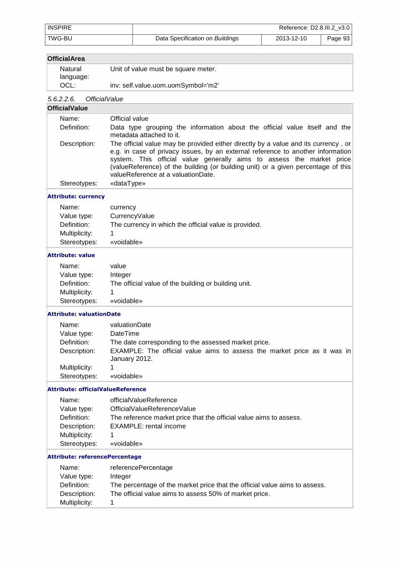
INSPIRE Reference: D2.8.III.2_v3.0
TWG-BU Data Specification on Buildings 2013-12-10 Page 93
OfficialArea
Natural language:
Unit of value must be square meter.
OCL: inv: self.value.uom.uomSymbol='m2'
5.6.2.2.6. OfficialValue
OfficialValue
Name: Official value Definition: Data type grouping the information about the official value itself and the
metadata attached to it. Description: The official value may be provided either directly by a value and its currency , or
e.g. in case of privacy issues, by an external reference to another information system. This official value generally aims to assess the market price (valueReference) of the building (or building unit) or a given percentage of this valueReference at a valuationDate.
Stereotypes: «dataType»
Attribute: currency
Name: currency Value type: CurrencyValue Definition: The currency in which the official value is provided. Multiplicity: 1 Stereotypes: «voidable»
Attribute: value
Name: value Value type: Integer Definition: The official value of the building or building unit. Multiplicity: 1 Stereotypes: «voidable»
Attribute: valuationDate
Name: valuationDate Value type: DateTime Definition: The date corresponding to the assessed market price. Description: EXAMPLE: The official value aims to assess the market price as it was in
January 2012. Multiplicity: 1 Stereotypes: «voidable»
Attribute: officialValueReference
Name: officialValueReference Value type: OfficialValueReferenceValue Definition: The reference market price that the official value aims to assess. Description: EXAMPLE: rental income Multiplicity: 1 Stereotypes: «voidable»
Attribute: referencePercentage
Name: referencePercentage Value type: Integer Definition: The percentage of the market price that the official value aims to assess. Description: The official value aims to assess 50% of market price. Multiplicity: 1

INSPIRE Reference: D2.8.III.2_v3.0
TWG-BU Data Specification on Buildings 2013-12-10 Page 94
OfficialValue
Stereotypes: «voidable»
Attribute: informationSystemName
Name: informationSystemName Value type: PT_FreeText Definition: The name of an external information system where the official value may be
found. Description: It will be possible to find the official value of the building, building part or building
unit, using the external reference of the spatial object related to the given information system.
Multiplicity: 1 Stereotypes: «voidable»
Constraint: either value and currency or informationSystemName shall be provided
Natural language:
Either value and currency or informationSystemName shall be provided.
OCL: inv: (value->notEmpty() and currency->notEmpty()) or (informationSystemName->notEmpty())
Constraint: informationSystemName shall be present in one external reference
Natural language:
The informationSystemName shall be present in one of the external references of the spatial object.
OCL:
5.6.2.3. Code lists
5.6.2.3.1. CLGE_OfficialAreaReferenceValue
CLGE_OfficialAreaReferenceValue
Name: CLGE_OfficialAreaReferenceValue Definition: List of values for the reference of official area, as defined in the CLGE
measurement code for the floor area of buildings. SOURCE: http://www.eureal.eu/
Extensibility: open Identifier: http://inspire.ec.europa.eu/codelist/OfficialAreaReferenceValue Values: The allowed values for this code list comprise the values specified in Annex C
and additional values at any level defined by data providers. Annex C includes recommended values that may be used by data providers.
5.6.2.3.2. CurrencyValue
CurrencyValue
Name: CurrencyValue Definition: Code list for possible values of attribute currency Description: NOTE 1: include currencies from all European countries, including that are not
Member States of European Union. SOURCE: values are extracted from ISO 4217 standard. NOTE 2: this code list may be of interest not only for INSPIRE but also for other European applications and regulations ; so, in future, this code list might/should be managed outside INSPIRE.
Extensibility: open Identifier: http://inspire.ec.europa.eu/codelist/CurrencyValue Values: The allowed values for this code list comprise the values specified in Annex C
and additional values at any level defined by data providers. Annex C includes recommended values that may be used by data providers.

INSPIRE Reference: D2.8.III.2_v3.0
TWG-BU Data Specification on Buildings 2013-12-10 Page 95
5.6.2.3.3. EnergyPerformanceValue
EnergyPerformanceValue
Name: EnergyPerformanceValue Definition: Code list for possible values of energy performance of a building or building part
or building unit. Extensibility: open Identifier: http://inspire.ec.europa.eu/codelist/EnergyPerformanceValue Values: The allowed values for this code list comprise the values specified in Annex C
and additional values at any level defined by data providers. Annex C includes recommended values that may be used by data providers.
5.6.2.3.4. HeatingSourceValue
HeatingSourceValue
Name: HeatingSourceValue Definition: Code list for the possible values of the heating source of a building, building part
or building unit. Extensibility: open Identifier: http://inspire.ec.europa.eu/codelist/HeatingSourceValue Values: The allowed values for this code list comprise the values specified in Annex C
and additional values at any level defined by data providers. Annex C includes recommended values that may be used by data providers.
5.6.2.3.5. HeatingSystemValue
HeatingSystemValue
Name: HeatingSystemValue Definition: Code list giving the possible values for the heating system of a building, building
part or building unit. Extensibility: open Identifier: http://inspire.ec.europa.eu/codelist/HeatingSystemValue Values: The allowed values for this code list comprise the values specified in Annex C
and additional values at any level defined by data providers. Annex C includes recommended values that may be used by data providers.
5.6.2.3.6. InstallationNatureValue
InstallationNatureValue
Name: InstallationNatureValue Definition: Code list giving the possible values of an installation nature. Extensibility: open Identifier: http://inspire.ec.europa.eu/codelist/InstallationNatureValue Values: The allowed values for this code list comprise the values specified in Annex C
and additional values at any level defined by data providers. Annex C includes recommended values that may be used by data providers.
5.6.2.3.7. MaterialOfFacadeValue
MaterialOfFacadeValue
Name: MaterialOfFacadeValue Definition: Code list for the possible values of MaterialOfFacade Extensibility: open Identifier: http://inspire.ec.europa.eu/codelist/MaterialOfFacadeValue Values: The allowed values for this code list comprise the values specified in Annex C
and additional values at any level defined by data providers. Annex C includes recommended values that may be used by data providers.
5.6.2.3.8. MaterialOfRoofValue
MaterialOfRoofValue

INSPIRE Reference: D2.8.III.2_v3.0
TWG-BU Data Specification on Buildings 2013-12-10 Page 96
MaterialOfRoofValue
Name: MaterialOfRoofValue Definition: Code list for possible values of attribute MaterialOfRoof Extensibility: open Identifier: http://inspire.ec.europa.eu/codelist/MaterialOfRoofValue Values: The allowed values for this code list comprise the values specified in Annex C
and additional values at any level defined by data providers. Annex C includes recommended values that may be used by data providers.
5.6.2.3.9. MaterialOfStructureValue
MaterialOfStructureValue
Name: MaterialOfStructureValue Definition: Code list for possible values of attribute MaterialOfStructure. Extensibility: open Identifier: http://inspire.ec.europa.eu/codelist/MaterialOfStructureValue Values: The allowed values for this code list comprise the values specified in Annex C
and additional values at any level defined by data providers. Annex C includes recommended values that may be used by data providers.
5.6.2.3.10. OfficialAreaReferenceValue
OfficialAreaReferenceValue
Name: OfficialAreaReferenceValue Definition: The list of possible values for the reference of the official area. Description: The type of official area may be described either by using the values provided by
the CLGE measurement code for the floor area of buildings (which values are provided by the CLGE_OfficialAreaReferenceValue) or by using another standard (which values are provided by the empty code list OtherStandard OfficialAreaReferenceValue, this code list having to be defined at Member State level).
Extensibility: open Identifier: http://inspire.ec.europa.eu/codelist/OfficialAreaReferenceValue Values: The allowed values for this code list comprise the values specified in Annex C
and additional values at any level defined by data providers. Annex C includes recommended values that may be used by data providers.
5.6.2.3.11. OfficialValueReferenceValue
OfficialValueReferenceValue
Name: OfficialValueReferenceValue Definition: The list of possible values for referencing the official value of a building, building
part or building unit. Extensibility: open Identifier: http://inspire.ec.europa.eu/codelist/OfficialValueReferenceValue Values: The allowed values for this code list comprise the values specified in Annex C
and additional values at any level defined by data providers. Annex C includes recommended values that may be used by data providers.
5.6.2.3.12. OtherStandardOfficialAreaReferenceValue
OtherStandardOfficialAreaReferenceValue
Name: Other standard official area reference value Definition: Reference to a standard for official area code list. Extensibility: open Identifier: Values: The allowed values for this code list comprise the values specified in Annex C
and additional values at any level defined by data providers. Annex C includes recommended values that may be used by data providers.

INSPIRE Reference: D2.8.III.2_v3.0
TWG-BU Data Specification on Buildings 2013-12-10 Page 97
5.6.2.3.13. RoofTypeValue
RoofTypeValue
Name: RoofTypeValue Definition: Code list for the possible values of attribute roofType. Extensibility: open Identifier: http://inspire.ec.europa.eu/codelist/RoofTypeValue Values: The allowed values for this code list comprise the values specified in Annex C
and additional values at any level defined by data providers. Annex C includes recommended values that may be used by data providers.
5.6.2.3.14. SourceStatusValue
SourceStatusValue
Name: SourceStatusValue Definition: Code list for possible values of attribute sourceStatus (of Document). Extensibility: open Identifier: http://inspire.ec.europa.eu/codelist/SourceStatusValue Values: The allowed values for this code list comprise the values specified in Annex C
and additional values at any level defined by data providers. Annex C includes recommended values that may be used by data providers.
5.6.2.3.15. OtherConstructionNatureValue
OtherConstructionNatureValue
Name: OtherConstructionNatureValue Definition: Code list for the attribute other construction nature. Extensibility: open Identifier: http://inspire.ec.europa.eu/codelist/OtherConstructionNatureValue Values: The allowed values for this code list comprise the values specified in Annex C
and additional values at any level defined by data providers. Annex C includes recommended values that may be used by data providers.
5.6.2.4. Imported types (informative)
This section lists definitions for feature types, data types and enumerations and code lists that are defined in other application schemas. The section is purely informative and should help the reader understand the feature catalogue presented in the previous sections. For the normative documentation of these types, see the given references.
5.6.2.4.1. AbstractConstruction
AbstractConstruction (abstract)
Package: BuildingsBase Reference: INSPIRE Data specification on Buildings [DS-D2.8.III.2] Definition: Abstract spatial object type grouping the semantic properties of buildings,
building parts and of some optional spatial object types that may be added in order to provide more information about the theme Buildings.
Description: The optional spatial object types that may be added to core profiles are described in the extended profiles. The ones inheriting from the attributes of AbstractConstruction are Installation and OtherConstruction.
5.6.2.4.2. AddressRepresentation
AddressRepresentation
Package: Addresses Reference: INSPIRE Data specification on Addresses [DS-D2.8.I.5] Definition: Representation of an address spatial object for use in external application
schemas that need to include the basic, address information in a readable way. Description: NOTE 1 The data type includes the all necessary readable address components
as well as the address locator(s), which allows the identification of the address

INSPIRE Reference: D2.8.III.2_v3.0
TWG-BU Data Specification on Buildings 2013-12-10 Page 98
AddressRepresentation
spatial objects, e.g., country, region, municipality, address area, post code, street name and address number. It also includes an optional reference to the full address spatial object. NOTE 2 The datatype could be used in application schemas that wish to include address information e.g. in a dataset that registers buildings or properties.
5.6.2.4.3. Area
Area
Package: Units of Measure Reference: Geographic information -- Conceptual schema language [ISO/TS 19103:2005]
5.6.2.4.4. Boolean
Boolean
Package: Truth Reference: Geographic information -- Conceptual schema language [ISO/TS 19103:2005]
5.6.2.4.5. CadastralParcel
CadastralParcel
Package: CadastralParcels Reference: INSPIRE Data specification on Cadastral Parcels [DS-D2.8.I.6] Definition: Areas defined by cadastral registers or equivalent. Description: SOURCE [INSPIRE Directive:2007].
NOTE As much as possible, in the INSPIRE context, cadastral parcels should be forming a partition of national territory. Cadastral parcel should be considered as a single area of Earth surface (land and/or water), under homogeneous real property rights and unique ownership, real property rights and ownership being defined by national law (adapted from UN ECE 2004 and WG-CPI, 2006). By unique ownership is meant that the ownership is held by one or several joint owners for the whole parcel.
5.6.2.4.6. CurrentUseValue
CurrentUseValue
Package: BuildingsBase Reference: INSPIRE Data specification on Buildings [DS-D2.8.III.2] Definition: List of possible values indicating the current use. Description: SOURCE: This code list is partly based on and adapted from the Eurostat
classification of types of constructions (for the classification of residential buildings). NOTE: the values of this code list apply to buildings or building components where building components may be a building part (in core profiles) or a building unit (in extended profiles)
5.6.2.4.7. DateTime
DateTime
Package: Date and Time Reference: Geographic information -- Conceptual schema language [ISO/TS 19103:2005]
5.6.2.4.8. DocumentCitation
DocumentCitation
Package: Base Types 2 Reference: INSPIRE Generic Conceptual Model, version 3.4 [DS-D2.5] Definition: Citation for the purposes of unambiguously referencing a document.

INSPIRE Reference: D2.8.III.2_v3.0
TWG-BU Data Specification on Buildings 2013-12-10 Page 99
5.6.2.4.9. ExternalReference
ExternalReference
Package: BuildingsBase Reference: INSPIRE Data specification on Buildings [DS-D2.8.III.2] Definition: Reference to an external information system containing any piece of information
related to the spatial object.
5.6.2.4.10. Identifier
Identifier
Package: Base Types Reference: INSPIRE Generic Conceptual Model, version 3.4 [DS-D2.5] Definition: External unique object identifier published by the responsible body, which may
be used by external applications to reference the spatial object. Description: NOTE1 External object identifiers are distinct from thematic object identifiers.
NOTE 2 The voidable version identifier attribute is not part of the unique identifier of a spatial object and may be used to distinguish two versions of the same spatial object. NOTE 3 The unique identifier will not change during the life-time of a spatial object.
5.6.2.4.11. Integer
Integer
Package: Numerics Reference: Geographic information -- Conceptual schema language [ISO/TS 19103:2005]
5.6.2.4.12. Length
Length
Package: Units of Measure Reference: Geographic information -- Conceptual schema language [ISO/TS 19103:2005]
5.6.2.4.13. PT_FreeText
PT_FreeText
Package: Cultural and linguistic adapdability Reference: Geographic information -- Metadata -- XML schema implementation [ISO/TS
19139:2007]
5.6.2.4.14. Real
Real
Package: Numerics Reference: Geographic information -- Conceptual schema language [ISO/TS 19103:2005]
5.6.2.4.15. URI
URI
Package: basicTypes Reference: Geographic information -- Geography Markup Language (GML) [ISO
19136:2007]

INSPIRE Reference: D2.8.III.2_v3.0
TWG-BU Data Specification on Buildings 2013-12-10 Page 100
5.7 Application schema BuildingsExtended2D
5.7.1 Description
5.7.1.1. Narrative description <Buildings Extended 2D> application schema is an illustrative profile. It aims to be a recommendation for data providers willing to give more information than the basic one included in core 2D profile. This extended profile may be used as a whole or only partly, i.e. only a selection of proposed feature types and attributes may be added. More detailed information is provided in annex F. Extended2D profile is both:
- an extension of <Buildings 2D> profile, i.e. it includes buildings and building parts with their 2D geometric representation (defined in <Base 2D>) and the basic core properties inherited from <Buildings Base>
- an extension of <Building BaseExtended>, i.e. it includes its additional feature types (other constructions, installations and building units) and its additional properties, such as official information and more detailed physical description.

INSPIRE Reference: D2.8.III.2_v3.0
TWG-BU Data Specification on Buildings 2013-12-10 Page 101
In the above figure, the feature types defined by <Buildings extended2D> are displayed in blue.
Feature types Building and BuildingPart inherit both from o <Buildings 2D> : buildings and building parts get the 2D geometric representation defined in
this application schema and the core semantics inherited from <Buildings Base> application schema
o <Buildings Base extended>: building and building parts get the additional properties defined in this application schema, namely the official information coming from BuildingAndBuildingUnitInfo and the more detailed topographic description coming from BuildingInfo.
cla
ss
Bu
ild
ing
s -
Ex
ten
de
d 2
D
«fe
atu
reT
yp
e»
Bu
ild
ing
sE
xte
nd
ed
Ba
se
::B
uil
din
gIn
fo
«vo
ida
ble
»
+
he
igh
tBe
low
Gro
un
d:
Le
ng
th [
0..
1]
+
nu
mb
erO
fFlo
ors
Be
low
Gro
un
d:
In
teg
er
[0..
1]
+
flo
orD
istr
ibu
tio
n:
Flo
orR
an
ge
[1
..*]
+
flo
orD
esc
rip
tio
n:
Flo
orD
esc
rip
tio
n [
0..
*]
+
roo
fTyp
e:
Ro
ofT
yp
eV
alu
e [
0..
*]
+
ma
teri
alO
fFa
ca
de
: M
ate
ria
lOfF
aca
de
Va
lue
[0
..*]
+
ma
teri
alO
fRo
of:
M
ate
ria
lOfR
oo
fVa
lue
[0
..*]
+
ma
teri
alO
fStr
uctu
re:
Ma
teri
alO
fStr
uctu
reV
alu
e [
0..
*]
«fe
atu
reT
yp
e»
Bu
ild
ing
sE
xte
nd
ed
Ba
se
::A
bs
tra
ctB
uil
din
gU
nit
+
insp
ire
Id:
Id
en
tifi
er
+
exte
rna
lRe
fere
nce
: E
xte
rna
lRe
fere
nce
«vo
ida
ble
»
+
cu
rre
ntU
se:
Cu
rre
ntU
seV
alu
e [
0..
*]
«vo
ida
ble
, li
feC
ycle
Info
»
+
be
gin
Lif
esp
an
Ve
rsio
n:
Da
teT
ime
+
en
dL
ife
spa
nV
ers
ion
: D
ate
Tim
e [
0..
1]
«fe
atu
reT
yp
e»
Ins
tall
ati
on
+
ge
om
etr
y2
D:
GM
_P
rim
itiv
e
«fe
atu
reT
yp
e»
Oth
erC
on
str
uc
tio
n
+
ge
om
etr
y2
D:
GM
_P
rim
itiv
e
Ba
se p
acka
ge
2D
Co
re
«fe
atu
reT
yp
e»
Bu
ild
ing
sE
xte
nd
ed
Ba
se
::
Ab
str
ac
tOth
erC
on
str
uc
tio
n
«fe
atu
reT
yp
e»
Bu
ild
ing
sE
xte
nd
ed
Ba
se
::
Ab
str
ac
tIn
sta
lla
tio
n
«fe
atu
reT
yp
e»
Bu
ild
ing
sB
as
e::
Ab
str
ac
tCo
ns
tru
cti
on
+
insp
ire
Id:
Id
en
tifi
er
«vo
ida
ble
, li
feC
ycle
Info
»
+
be
gin
Lif
esp
an
Ve
rsio
n:
Da
teT
ime
+
en
dL
ife
spa
nV
ers
ion
: D
ate
Tim
e [
0..
1]
«vo
ida
ble
»
+
co
nd
itio
nO
fCo
nst
ructi
on
: C
on
dit
ion
OfC
on
stru
cti
on
Va
lue
+
da
teO
fCo
nst
ructi
on
: D
ate
OfE
ve
nt
[0..
1]
+
da
teO
fDe
mo
liti
on
: D
ate
OfE
ve
nt
[0..
1]
+
da
teO
fRe
no
va
tio
n:
Da
teO
fEve
nt
[0..
1]
+
ele
va
tio
n:
Ele
va
tio
n [
0..
*]
+
exte
rna
lRe
fere
nce
: E
xte
rna
lRe
fere
nce
[0
..*]
+
he
igh
tAb
ove
Gro
un
d:
He
igh
tAb
ove
Gro
un
d [
0..
*]
+
na
me
: G
eo
gra
ph
ica
lNa
me
[0
..*]
«fe
atu
reT
yp
e»
Bu
ild
ing
sB
as
e::
Ab
str
ac
tBu
ild
ing
«vo
ida
ble
»
+
bu
ild
ing
Na
ture
: B
uil
din
gN
atu
reV
alu
e [
0..
*]
+
cu
rre
ntU
se:
Cu
rre
ntU
se [
0..
*]
+
nu
mb
erO
fDw
ell
ing
s:
Inte
ge
r [0
..1
]
+
nu
mb
erO
fBu
ild
ing
Un
its:
In
teg
er
[0..
1]
+
nu
mb
erO
fFlo
ors
Ab
ove
Gro
un
d:
In
teg
er
[0..
1]
«fe
atu
reT
yp
e»
Bu
ild
ing
sB
as
e::
Bu
ild
ing
Pa
rt
«fe
atu
reT
yp
e»
Bu
ild
ing
sB
as
e::
Bu
ild
ing
«fe
atu
reT
yp
e»
Bu
ild
ing
s2
D::
Bu
ild
ing
+
ge
om
etr
y2
D:
Bu
ild
ing
Ge
om
etr
y2
D
co
ns
tra
ints
{sin
gle
Re
fere
nce
Ge
om
etr
y}
{Bu
ild
ing
pa
rts
sha
ll b
e 2
D}
«fe
atu
reT
yp
e»
Bu
ild
ing
s2
D::
Bu
ild
ing
Pa
rt
+
ge
om
etr
y2
D:
Bu
ild
ing
Ge
om
etr
y2
D [
1..
*]
co
ns
tra
ints
{sin
gle
Re
fere
nce
Ge
om
etr
y}
Ba
se e
xte
nd
ed
«fe
atu
reT
yp
e»
Bu
ild
ing
Un
it
«vo
ida
ble
»
+
ge
om
etr
y2
D:
GM
_P
rim
itiv
e
«fe
atu
reT
yp
e»
Bu
ild
ing
«fe
atu
reT
yp
e»
Bu
ild
ing
Pa
rt
Co
nst
rain
ts t
o u
se
Bu
ild
ing
sCo
re2
D::
Inst
all
ati
on
an
d
Bu
ild
ing
sCo
re2
D::
Bu
ild
ing
Un
it
for
the
un
it a
nd
in
sta
lla
tio
n
pro
pe
rtie
s.
«fe
atu
reT
yp
e»
Bu
ild
ing
sE
xte
nd
ed
Ba
se
::
Bu
ild
ing
An
dB
uil
din
gU
nit
Info
«vo
ida
ble
»
+
co
nn
ecti
on
To
Ele
ctr
icit
y:
Bo
ole
an
[0
..1
]
+
co
nn
ecti
on
To
Ga
s:
Bo
ole
an
[0
..1
]
+
co
nn
ecti
on
To
Se
wa
ge
: B
oo
lea
n [
0..
1]
+
co
nn
ecti
on
To
Wa
ter:
B
oo
lea
n [
0..
1]
+
do
cu
me
nt:
D
ocu
me
nt
[0..
*]
+
en
erg
yP
erf
orm
an
ce
: E
ne
rgyP
erf
orm
an
ce
[0
..1
]
+
he
ati
ng
So
urc
e:
He
ati
ng
So
urc
eV
alu
e [
0..
*]
+
he
ati
ng
Syst
em
: H
ea
tin
gS
yst
em
Va
lue
[0
..*]
+
ad
dre
ss:
Ad
dre
ssR
ep
rese
nta
tio
n [
0..
*]
+
off
icia
lAre
a:
Off
icia
lAre
a [
0..
*]
+
off
icia
lVa
lue
: O
ffic
ialV
alu
e [
0..
*]
+b
uil
din
gU
nit
«vo
ida
ble
»
0..
*
+in
sta
lla
tio
n
«vo
ida
ble
»
0..
*
+p
art
s
«vo
ida
ble
»
0..
*
Figure 53: The <Buildings Extended2D> application schema

INSPIRE Reference: D2.8.III.2_v3.0
TWG-BU Data Specification on Buildings 2013-12-10 Page 102
The application schema <Buildings extended2D> does not define any other attribute for buildings and building parts.
Feature types OtherConstruction and Installation get the attribute about ―nature‖ defined in the <Buildings Base extended> application schema and the core attributes inherited from AbstractConstruction in <Buildings Base> application schema.
In addition, <Buildings Extended2D> defines their 2D geometric representation as a generic GM_Object.
Feature types BuildingUnit inherits only the attributes defined directly in <Buildings Base Extended>, namely the specific attributes of AbstractBuildingUnit (e.g. the mandatory external reference) and the attributes common with buildings and building parts defined in BuildingAndBuildingUnitInfo.
In addition, <Buildings Extended2D> defines their 2D geometric representation as a generic GM_Object. Note that, in opposition to the other feature types of theme Buildings, this geometry is voidable
5.7.1.2. UML Overview See previous Figure 53.
5.7.2 Feature catalogue
Feature catalogue metadata
Application Schema INSPIRE Application Schema BuildingsExtended2D
Version number 3.0
Types defined in the feature catalogue
Type Package Stereotypes
Building BuildingsExtended2D «featureType»
BuildingPart BuildingsExtended2D «featureType»
BuildingUnit BuildingsExtended2D «featureType»
Installation BuildingsExtended2D «featureType»
OtherConstruction BuildingsExtended2D «featureType»
5.7.2.1. Spatial object types
5.7.2.1.1. BuildingUnit
BuildingUnit
Name: Building unit Subtype of: AbstractBuildingUnit Definition: A BuildingUnit is a subdivision of Building with its own lockable access from the
outside or from a common area (i.e. not from another BuildingUnit), which is atomic, functionally independent, and may be separately sold, rented out, inherited, etc.
Description: Building units are spatial objects aimed at subdividing buildings and/or building parts into smaller parts that are treated as seperate entities in daily life. A building unit is homogeneous, regarding management aspects. EXAMPLES: It may be e.g. an apartment in a condominium, a terraced house, or a shop inside a shopping arcade. NOTE 1: According to national regulations, a building unit may be a flat, a cellar, a garage or set of a flat, a cellar and a garage. NOTE 2: According to national regulation, a building that is one entity for daily life (typically, a single family house) may be considered as a Building composed of one BuildingUnit or as a Building composed of zero BuildingUnit.
Stereotypes: «featureType»

INSPIRE Reference: D2.8.III.2_v3.0
TWG-BU Data Specification on Buildings 2013-12-10 Page 103
BuildingUnit
Attribute: geometry2D
Name: Geometry 2D Value type: GM_Primitive Definition: The 2D or 2,5 D geometric representation of the building unit. Description: EXAMPLE: the building unit may be represented by its floor surface or by a
simple point. Multiplicity: 1 Stereotypes: «voidable»
5.7.2.1.2. Installation
Installation
Name: Installation Subtype of: AbstractInstallation Definition: An external construction (of small size) or an external device serving the building
or building part. Description: EXAMPLES: stairway, solar panel, external lift Stereotypes: «featureType»
Attribute: geometry2D
Name: Geometry 2D Value type: GM_Primitive Definition: 2D or 2,5 D geometric representation of the other construction. Multiplicity: 1
5.7.2.1.3. OtherConstruction
OtherConstruction
Name: Other construction Subtype of: AbstractOtherConstruction Definition: An OtherConstruction is a self-standing construction that belongs to theme
Buildings and that is not a Building. Description: NOTE 1: the main difference between a building and an other construction is the
fact that an other construction does not need to be enclosed. NOTE 2: the other constructions to be considered under scope of theme buildings are the constructions that are not present in another INSPIRE theme and that are necessary for environmental use cases, such as the ones considered in this data specification. EXAMPLES: bridge, acoustic fence, city wall.
Stereotypes: «featureType»
Attribute: geometry2D
Name: Geometry 2D Value type: GM_Primitive Definition: <font color="#0f0f0f">Geometric representation of the building. Multiplicity: 1
5.7.2.1.4. Building
Building
Name: Building Subtype of: BuildingInfoBuilding Definition: A Building is an enclosed construction above and/or underground, used or
intended for the shelter of humans, animals or things or for the production of economic goods. A building refers to any structure permanently constructed or erected on its site.

INSPIRE Reference: D2.8.III.2_v3.0
TWG-BU Data Specification on Buildings 2013-12-10 Page 104
Building
Stereotypes: «featureType»
5.7.2.1.5. BuildingPart
BuildingPart
Name: Building part Subtype of: BuildingInfoBuildingPart Definition: A BuildingPart is a sub-division of a Building that might be considered itself as a
building. Description: NOTE 1: A BuildingPart is homogeneous related to its physical, functional or
temporal aspects. NOTE 2: Building and BuildingPart share the same set of properties. EXAMPLE: A Building may be composed of two BuildingParts having different heights above ground.
Stereotypes: «featureType»
5.7.2.2. Imported types (informative)
This section lists definitions for feature types, data types and enumerations and code lists that are defined in other application schemas. The section is purely informative and should help the reader understand the feature catalogue presented in the previous sections. For the normative documentation of these types, see the given references.
5.7.2.2.1. AbstractBuildingUnit
AbstractBuildingUnit (abstract)
Package: BuildingsExtendedBase Reference: INSPIRE Data specification on Buildings [DS-D2.8.III.2] Definition: Abstract spatial object type grouping the semantic properties of building units. A
BuildingUnit is a subdivision of Building with its own lockable access from the outside or from a common area (i.e. not from another BuildingUnit), which is atomic, functionally independent, and may be separately sold, rented out, inherited, etc.
Description: Building units are spatial objects aimed at subdividing buildings and/or building parts into smaller parts that are treated as seperate entities in daily life. A building unit is homogeneous, regarding management aspects. EXAMPLES: It may be e.g. an apartment in a condominium, a terraced house, or a shop inside a shopping arcade. NOTE 1: According to national regulations, a building unit may be a flat, a cellar, a garage or set of a flat, a cellar and a garage. NOTE 2: According to national regulation, a building that is one entity for daily life (typically, a single family house) may be considered as a Building composed of one BuildingUnit or as a Building composed of zero BuildingUnit.
5.7.2.2.2. AbstractInstallation
AbstractInstallation (abstract)
Package: BuildingsExtendedBase Reference: INSPIRE Data specification on Buildings [DS-D2.8.III.2] Definition: Abstract spatial object type grouping the semantic properties of installations. An
external construction (of small size) or an external device serving the building or building part.
Description: EXAMPLES: stairway, solar panel, external lift
5.7.2.2.3. AbstractOtherConstruction
AbstractOtherConstruction (abstract)
Package: BuildingsExtendedBase Reference: INSPIRE Data specification on Buildings [DS-D2.8.III.2]
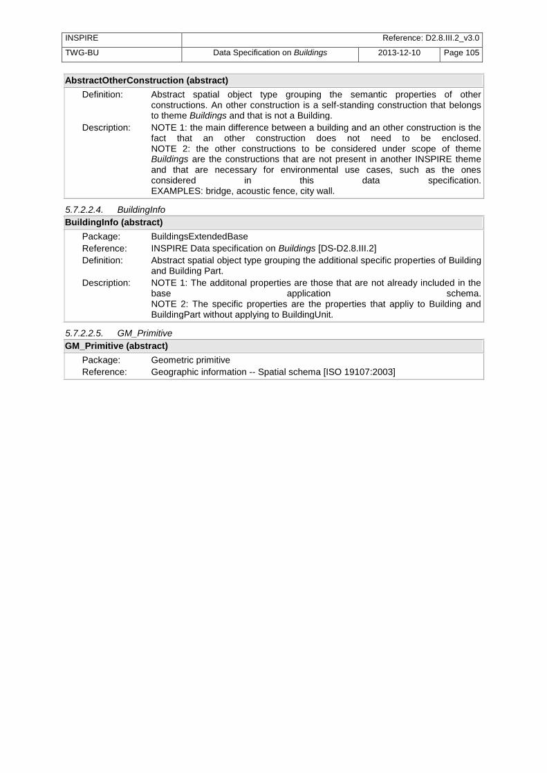
INSPIRE Reference: D2.8.III.2_v3.0
TWG-BU Data Specification on Buildings 2013-12-10 Page 105
AbstractOtherConstruction (abstract)
Definition: Abstract spatial object type grouping the semantic properties of other constructions. An other construction is a self-standing construction that belongs to theme Buildings and that is not a Building.
Description: NOTE 1: the main difference between a building and an other construction is the fact that an other construction does not need to be enclosed. NOTE 2: the other constructions to be considered under scope of theme Buildings are the constructions that are not present in another INSPIRE theme and that are necessary for environmental use cases, such as the ones considered in this data specification. EXAMPLES: bridge, acoustic fence, city wall.
5.7.2.2.4. BuildingInfo
BuildingInfo (abstract)
Package: BuildingsExtendedBase Reference: INSPIRE Data specification on Buildings [DS-D2.8.III.2] Definition: Abstract spatial object type grouping the additional specific properties of Building
and Building Part. Description: NOTE 1: The additonal properties are those that are not already included in the
base application schema. NOTE 2: The specific properties are the properties that appliy to Building and BuildingPart without applying to BuildingUnit.
5.7.2.2.5. GM_Primitive
GM_Primitive (abstract)
Package: Geometric primitive Reference: Geographic information -- Spatial schema [ISO 19107:2003]

INSPIRE Reference: D2.8.III.2_v3.0
TWG-BU Data Specification on Buildings 2013-12-10 Page 106
5.8 Application schema BuildingsExtended3D
5.8.1 Description
5.8.1.1. Narrative description <Buildings Extended 3D> application schema is an illustrative profile. It aims to be a recommendation for data providers willing to give more information than the basic one included in core 3D profile. This extended profile may be used as a whole or only partly, i.e. only a selection of proposed feature types and attributes may be added. More detailed information is provided in annex F. <Buildings Extended3D> profile is both:
- an extension of <Buildings 3D> application schema, i.e. it includes buildings and building parts with their 2D geometric representation (defined in <Base 3D>) and the basic core properties inherited from <Buildings Base>
- an extension of <Building BaseExtended>, i.e. it includes its additional feature types (other constructions, installations and building units) and its additional properties, such as official information and more detailed physical description.
In addition, <Buildings Extended3D> offers a more detailed description of buildings and building parts by defining their physical components, such as roof, walls, ground, openings, room and by describing mechanisms to attach a texture to these components.
5.8.1.1.1. Main feature types

INSPIRE Reference: D2.8.III.2_v3.0
TWG-BU Data Specification on Buildings 2013-12-10 Page 107
Figure 54: The main feature types of <Buildings Extended3D>
In the above figure, the feature types defined by <Buildings extended3D> are displayed in pink.
Feature types Building and BuildingPart inherit both from o <Buildings 3D> : buildings and building parts get the 3D geometric representation defined in
this application schema and the core semantics inherited from <Buildings Base> application schema
o <Buildings Base extended>: building and building parts get the additional properties defined in this application schema, namely the official information coming from BuildingAndBuildingUnitInfo and the more detailed topographic description coming from BuildingInfo.
cla
ss
Bu
ild
ing
Ex
ten
de
d3
D -
Ma
in s
pa
tia
l o
bje
ct
typ
...
«fe
atu
reT
yp
e»
Oth
erC
on
str
uc
tio
n
+
ge
om
etr
y3
D:
GM
_O
bje
ct
«vo
ida
ble
»
+
ge
om
etr
y2
D:
GM
_P
rim
itiv
e [
0..
*]
«fe
atu
reT
yp
e»
Bu
ild
ing
co
ns
tra
ints
{Ge
om
etr
yW
he
nN
oP
art
s}
{Bu
ild
ing
un
its
sha
ll b
e 3
D}
{In
sta
lla
tio
ns
sha
ll b
e 3
D}
«fe
atu
reT
yp
e»
Bu
ild
ing
Pa
rt
co
ns
tra
ints
{Ma
nd
ato
ryG
eo
me
try}
{Bu
ild
ing
un
its
sha
ll b
e 3
D}
{In
sta
lla
tio
ns
sha
ll b
e 3
D}
«fe
atu
reT
yp
e»
Ins
tall
ati
on
+
ge
om
etr
y3
D:
GM
_O
bje
ct
«vo
ida
ble
»
+
ge
om
etr
y2
D:
GM
_P
rim
itiv
e [
0..
*]
«fe
atu
reT
yp
e»
Bu
ild
ing
Un
it
+
ge
om
etr
y3
D:
GM
_M
ult
iSo
lid
«vo
ida
ble
»
+
ge
om
etr
y2
D:
GM
_P
rim
itiv
e [
0..
*]
«fe
atu
reT
yp
e»
Bu
ild
ing
sE
xte
nd
ed
Ba
se
::A
bs
tra
ctB
uil
din
gU
nit
+
insp
ire
Id:
Id
en
tifi
er
+
exte
rna
lRe
fere
nce
: E
xte
rna
lRe
fere
nce
«vo
ida
ble
»
+
cu
rre
ntU
se:
Cu
rre
ntU
seV
alu
e [
0..
*]
«vo
ida
ble
, li
feC
ycle
Info
»
+
be
gin
Lif
esp
an
Ve
rsio
n:
Da
teT
ime
+
en
dL
ife
spa
nV
ers
ion
: D
ate
Tim
e [
0..
1]
«fe
atu
reT
yp
e»
Bu
ild
ing
sB
as
e::
Ab
str
ac
tCo
ns
tru
cti
on
+
insp
ire
Id:
Id
en
tifi
er
«vo
ida
ble
, li
feC
ycle
Info
»
+
be
gin
Lif
esp
an
Ve
rsio
n:
Da
teT
ime
+
en
dL
ife
spa
nV
ers
ion
: D
ate
Tim
e [
0..
1]
«vo
ida
ble
»
+
co
nd
itio
nO
fCo
nst
ructi
on
: C
on
dit
ion
OfC
on
stru
cti
on
Va
lue
+
da
teO
fCo
nst
ructi
on
: D
ate
OfE
ve
nt
[0..
1]
+
da
teO
fDe
mo
liti
on
: D
ate
OfE
ve
nt
[0..
1]
+
da
teO
fRe
no
va
tio
n:
Da
teO
fEve
nt
[0..
1]
+
ele
va
tio
n:
Ele
va
tio
n [
0..
*]
+
exte
rna
lRe
fere
nce
: E
xte
rna
lRe
fere
nce
[0
..*]
+
he
igh
tAb
ove
Gro
un
d:
He
igh
tAb
ove
Gro
un
d [
0..
*]
+
na
me
: G
eo
gra
ph
ica
lNa
me
[0
..*]
«fe
atu
reT
yp
e»
Bu
ild
ing
sE
xte
nd
ed
Ba
se
::A
bs
tra
ctI
ns
tall
ati
on
+
inst
all
ati
on
Na
ture
: I
nst
all
ati
on
Na
ture
Va
lue
«fe
atu
reT
yp
e»
Bu
ild
ing
sE
xte
nd
ed
Ba
se
::A
bs
tra
ctO
the
rCo
ns
tru
cti
on
+
oth
erC
on
stru
cti
on
Na
ture
: O
the
rCo
nst
ructi
on
Na
ture
Va
lue
«fe
atu
reT
yp
e»
Bu
ild
ing
sE
xte
nd
ed
Ba
se
::B
uil
din
gIn
fo
«vo
ida
ble
»
+
he
igh
tBe
low
Gro
un
d:
Le
ng
th [
0..
1]
+
nu
mb
erO
fFlo
ors
Be
low
Gro
un
d:
In
teg
er
[0..
1]
+
flo
orD
istr
ibu
tio
n:
Flo
orR
an
ge
[1
..*]
+
flo
orD
esc
rip
tio
n:
Flo
orD
esc
rip
tio
n [
0..
*]
+
roo
fTyp
e:
Ro
ofT
yp
eV
alu
e [
0..
*]
+
ma
teri
alO
fFa
ca
de
: M
ate
ria
lOfF
aca
de
Va
lue
[0
..*]
+
ma
teri
alO
fRo
of:
M
ate
ria
lOfR
oo
fVa
lue
[0
..*]
+
ma
teri
alO
fStr
uctu
re:
Ma
teri
alO
fStr
uctu
reV
alu
e [
0..
*]
«fe
atu
reT
yp
e»
Bu
ild
ing
s3
D::
Bu
ild
ing
+
ge
om
etr
y3
DL
oD
1:
Bu
ild
ing
Ge
om
etr
y3
DL
oD
1 [
0..
1]
+
ge
om
etr
y3
DL
oD
2:
Bu
ild
ing
Ge
om
etr
y3
DL
oD
2 [
0..
1]
+
ge
om
etr
y3
DL
oD
3:
Bu
ild
ing
Ge
om
etr
y3
DL
oD
[0
..1
]
+
ge
om
etr
y3
DL
oD
4:
Bu
ild
ing
Ge
om
etr
y3
DL
oD
[0
..1
]
«vo
ida
ble
»
+
ge
om
etr
y2
D:
Bu
ild
ing
Ge
om
etr
y2
D [
0..
*]
co
ns
tra
ints
{Ge
om
etr
yW
he
nN
oP
art
s}
{Bu
ild
ing
pa
rts
sha
ll b
e 3
D}
«fe
atu
reT
yp
e»
Bu
ild
ing
s3
D::
Bu
ild
ing
Pa
rt
+
ge
om
etr
y3
DL
oD
1:
Bu
ild
ing
Ge
om
etr
y3
DL
oD
1 [
0..
1]
+
ge
om
etr
y3
DL
oD
2:
Bu
ild
ing
Ge
om
etr
y3
DL
oD
2 [
0..
1]
+
ge
om
etr
y3
DL
oD
3:
Bu
ild
ing
Ge
om
etr
y3
DL
oD
[0
..1
]
+
ge
om
etr
y3
DL
oD
4:
Bu
ild
ing
Ge
om
etr
y3
DL
oD
[0
..1
]
«vo
ida
ble
»
+
ge
om
etr
y2
D:
Bu
ild
ing
Ge
om
etr
y2
D [
0..
*]
co
ns
tra
ints
{Ma
nd
ato
ryG
eo
me
try}
«fe
atu
reT
yp
e»
Bu
ild
ing
sB
as
e::
Ab
str
ac
tBu
ild
ing
«vo
ida
ble
»
+
bu
ild
ing
Na
ture
: B
uil
din
gN
atu
reV
alu
e [
0..
*]
+
cu
rre
ntU
se:
Cu
rre
ntU
se [
0..
*]
+
nu
mb
erO
fDw
ell
ing
s:
Inte
ge
r [0
..1
]
+
nu
mb
erO
fBu
ild
ing
Un
its:
In
teg
er
[0..
1]
+
nu
mb
erO
fFlo
ors
Ab
ove
Gro
un
d:
In
teg
er
[0..
1]
«fe
atu
reT
yp
e»
Bu
ild
ing
sB
as
e::
Bu
ild
ing
Pa
rt
«fe
atu
reT
yp
e»
Bu
ild
ing
sB
as
e::
Bu
ild
ing
Bu
ild
ing
s -
Ba
seB
uil
din
gs
- E
xte
nd
ed
Ba
se
Bu
ild
ing
s -
Co
re 3
D
«fe
atu
reT
yp
e»
Bu
ild
ing
sE
xte
nd
ed
Ba
se
::B
uil
din
gA
nd
Bu
ild
ing
Un
itIn
fo
«vo
ida
ble
»
+
co
nn
ecti
on
To
Ele
ctr
icit
y:
Bo
ole
an
[0
..1
]
+
co
nn
ecti
on
To
Ga
s:
Bo
ole
an
[0
..1
]
+
co
nn
ecti
on
To
Se
wa
ge
: B
oo
lea
n [
0..
1]
+
co
nn
ecti
on
To
Wa
ter:
B
oo
lea
n [
0..
1]
+
do
cu
me
nt:
D
ocu
me
nt
[0..
*]
+
en
erg
yP
erf
orm
an
ce
: E
ne
rgyP
erf
orm
an
ce
[0
..1
]
+
he
ati
ng
So
urc
e:
He
ati
ng
So
urc
eV
alu
e [
0..
*]
+
he
ati
ng
Syst
em
: H
ea
tin
gS
yst
em
Va
lue
[0
..*]
+
ad
dre
ss:
Ad
dre
ssR
ep
rese
nta
tio
n [
0..
*]
+
off
icia
lAre
a:
Off
icia
lAre
a [
0..
*]
+
off
icia
lVa
lue
: O
ffic
ialV
alu
e [
0..
*]
+p
art
s
«vo
ida
ble
»
0..
*
+in
sta
lla
tio
n
«vo
ida
ble
»
0..
*
+b
uil
din
gU
nit
«vo
ida
ble
» 0..
*

INSPIRE Reference: D2.8.III.2_v3.0
TWG-BU Data Specification on Buildings 2013-12-10 Page 108
The application schema <Buildings extended3D> does not define any other attribute for buildings and building parts.
Feature types OtherConstruction and Installation get the attribute about ―nature‖ defined in the <Buildings Base extended> application schema and the core attributes inherited from AbstractConstruction in <Buildings Base> application schema.
In addition, <Buildings Extended2D> defines their 3D geometric representation as a generic GM_Object (that shall obviously be given with 3D coordinates).
Feature types BuildingUnit inherits only the attributes defined directly in <Buildings Base Extended>, namely the specific attributes of AbstractBuildingUnit (e.g. the mandatory external reference) and the attributes common with buildings and building parts defined in BuildingAndBuildingUnitInfo.
In addition, <Buildings Extended3D> defines their 3D geometric representation as a GM_MultiSolid.
5.8.1.1.2. The 3D building model As in <Buildings 2D>, the buildings and building parts may be represented by a solid or a multi-surface, according to the various LoDs of City GML. Moreover, the components of the building may also be semantically described by specific feature types:
in LoD2 : boundary surfaces(e.g. walls and roof ) and installations
in LoD3 : openings (doors and windows) are added
in Lod4: the interior of building (building units, rooms, internal installations) are added. class BuildingExtended3D - Spatial Representation Details
«featureType»
BoundarySurface
+ inspireId: Identifier
+ geometry3D: BoundaryGeometry3D
«voidable, l ifeCycleInfo»
+ beginLifespanVersion: DateTime
+ endLifespanVersion: DateTime [0..1]
«featureType»
WallSurface
«voidable»
+ materialOfWall: MaterialOfFacadeValue [0..1]
«featureType»
RoofSurface
«voidable»
+ materialOfRoof: MaterialOfRoofValue [0..*]
«featureType»
GroundSurface
AbstractOtherConstruction
«featureType»
OtherConstruction
+ geometry3D: GM_Object
«voidable»
+ geometry2D: GM_Primitive [0..*]
Building
BuildingInfo
«featureType»
Building
constraints
{GeometryWhenNoParts}
{Building units shall be 3D}
{Installations shall be 3D}
BuildingInfo
BuildingPart
«featureType»
BuildingPart
constraints
{MandatoryGeometry}
{Building units shall be 3D}
{Installations shall be 3D}
«featureType»
Opening
+ inspireId: Identifier
+ geometry3D: BoundaryGeometry3D
«voidable, l ifeCycleInfo»
+ beginLifespanVersion: DateTime
+ endLifespanVersion: DateTime [0..1]
«featureType»
ClosureSurface
«featureType»
Room
+ geometry3D: GM_Solid
+ roomNature: RoomNatureValue [0..1]
«voidable»
+ inspireId: Identifier [0..1]
«voidable, l ifeCycleInfo»
+ beginLifespanVersion: DateTime
+ endLifespanVersion: DateTime [0..1]
«featureType»
InteriorInstallation
+ geometry3D: GM_Object
+ installationNature: InternalInstallationNatureValue
«voidable»
+ inspireId: Identifier [0..1]
«voidable, l ifeCycleInfo»
+ beginLifespanVersion: DateTime
+ endLifespanVersion: DateTime [0..1]
«featureType»
OuterCeilingSurface
«featureType»
OuterFloorSurface
«featureType»
Door
«featureType»
Window
AbstractInstallation
«featureType»
Installation
+ geometry3D: GM_Object
«voidable»
+ geometry2D: GM_Primitive [0..*]
AbstractBuildingUnit
«featureType»
BuildingUnit
+ geometry3D: GM_MultiSolid
«voidable»
+ geometry2D: GM_Primitive [0..*]
+boundedBy
«voidable»
0..*
+boundedBy
«voidable»
0..*
+room
«voidable»0..*
+room
«voidable»
0..*
+opening
0..*
+interiorInstallation
«voidable»
0..*
+room
«voidable»
0..*
+boundedBy
«voidable»
0..*
+boundedBy
«voidable»
0..*
+interiorInstallation
«voidable»0..*
Figure 55: Modeling of LoD2, LoD3 and LoD4
In the Figure 55, the main feature types (Building, BuildingPart, BuildingUnit,Installation, OtherConstruction) are represented in pink, without their attributes. These attributes have been described in previous paragraph and figure. The new feature types are represented in orange.
LoD3
LoD2 (boundary surfaces)
LoD 4

INSPIRE Reference: D2.8.III.2_v3.0
TWG-BU Data Specification on Buildings 2013-12-10 Page 109
Figure 56: Examples of use of OuterFloorSurface and OuterCeilingSurface
LoD 4 relates to description of building interior. In CityGML, it is limited to the representation of Rooms and InteriorInstallations; in INSPIRE model, the representation of BuildingUnits has been added. Feature types BuildingUnit and Room may be represented separately or together; in last case, the BuildingUnit will be composed of Rooms.
5.8.1.1.3. Geometry of 3D feature types The geometry of 3D feature types has to be provided using one of these 5 types:
BuildingGeometry3D: it is the data type defined in core 3D profile. It is used to represent the 2 core feature types : buildings and building parts.
GM_Solid or GM_MultiSolid: it is the simple geometry primitive to represent the volumetric features related to of the building interior, i.e. rooms and building units. Note that these feature types have to be represented only in LoD4. The GM_Solid has to be used for rooms and the GM_MultiSolid for the building units.
BoundaryGeometry3D : this data type has to be used to represent the objects that are surfaces, i.e. wall surfaces, roof surfaces, closure surfaces, ground surfaces, outer ceiling surfaces, outer floor surface and openings (doors and windows). The boundary surface may be represented at different levels of detail, namely LoD2, LoD3 and LoD4. It is recommended to provide the accuracy of this geometric representation, both in its horizontal and vertical dimensions (see figure below).
GM_Object: this generic geometric primitive has to be used to represent the objects whose shape may be a volume, a surface or a line. This data type is used for internal and external installations and for other constructions. For instance:
o An antenna may be represented by a vertical line o Solar panel may be represented by a surface o Dormer may be represented by a volume / solid.
NOTE: In <Buildings Extended 3D> spatial objects may be solid, surfaces, lines or even points but their geometry has to be given with 3 coordinates.

INSPIRE Reference: D2.8.III.2_v3.0
TWG-BU Data Specification on Buildings 2013-12-10 Page 110
class BuildingExtended3D - Code Lists and Data Types
«dataType»
BoundaryGeometry3D
+ LoD2MultiSurface: GM_MultiSurface [0..1]
+ LoD3MultiSurface: GM_MultiSurface [0..1]
+ LoD4MultiSurface: GM_MultiSurface [0..1]
«voidable»
+ horizontalGeometryEstimatedAccuracyLoD2: Length [0..1]
+ horizontalGeometryEstimatedAccuracyLoD3: Length [0..1]
+ horizontalGeometryEstimatedAccuracyLoD4: Length [0..1]
+ verticalGeometryEstimatedAccuracyLoD2: Length [0..1]
+ verticalGeometryEstimatedAccuracyLoD3: Length [0..1]
+ verticalGeometryEstimatedAccuracyLoD4: Length [0..1]
constraints
{atLeastOneMandatoryGeometry}
Figure 57: The data type BoundaryGeometry3D

INSPIRE Reference: D2.8.III.2_v3.0
TWG-BU Data Specification on Buildings 2013-12-10 Page 111
5.8.1.1.4. The appearance model The INSIRE appearance model is based on City GML one. See more details about how a texture may be attached to the main features of the building model in annex D.
class BuildingExtended3D - Textural Representation Details
«dataType»
TextCoordGen
+ worldToTexture: TransformationMatrix3x4
«dataType»
TextCoordList
+ ring: URI
+ textureCoordinates: Number [0..*] {ordered}
«dataType»
TextureParametrization
«featureType»
ParameterizedTexture
+ imageURI: URI
+ mimeType: MimeTypeValue
+ textureType: TextureTypeValue
«codeList»
MimeTypeValue
«dataType»
TransformationMatrix3x4
+ elements: Number [0..*] {ordered}
«codeList»
TextureTypeValue
Building
BuildingInfo
«featureType»
Building
BuildingInfo
BuildingPart
«featureType»
BuildingPart
AbstractOtherConstruction
«featureType»
OtherConstruction
+ geometry3D: GM_Object
«voidable»
+ geometry2D: GM_Primitive [0..*]
AbstractInstallation
«featureType»
Installation
+ geometry3D: GM_Object
«voidable»
+ geometry2D: GM_Primitive [0..*]
image/png,
image/jpeg, image/tiff,
image/bmp, image/gif.
specific, typical
+textureParams 1..*
uri:anyURI
+texture 0..*
+appearance
«voidable»
0..*
+appearance
«voidable»
0..*
+appearance
«voidable» 0..*+appearance
«voidable»
0..*
Figure 58: The appearance part (simplification of CityGML appearance model)
5.8.1.2. UML Overview See previous figures.
5.8.1.3. Identifier management NOTE: For the detailed feature types of <Buildings Extended3D> application schema (such as roofs, walls, openings, rooms), the attribute inspireId is voidable whereas it is mandatory for the main feature types (buildings, buildings parts, installations, building units, other constructions).

INSPIRE Reference: D2.8.III.2_v3.0
TWG-BU Data Specification on Buildings 2013-12-10 Page 112
5.8.1.4. Geometry representation Art. 12(1) of Regulation 1089/2010 restricts the value domain of spatial properties to the Simple Feature spatial schema as defined in the OpenGIS® Implementation Standard for Geographic information – Simple feature access – Part 1: Common architecture, version 1.2.1, unless specified otherwise for a specific spatial data theme or type.
TG Requirement By way of derogation from article 12(1), the value domain of spatial properties
used in the Buildings 3D package shall not be restricted to simple feature.
5.8.2 Feature catalogue
Feature catalogue metadata
Application Schema INSPIRE Application Schema BuildingsExtended3D
Version number 3.0
Types defined in the feature catalogue
Type Package Stereotypes
BoundaryGeometry3D BuildingsExtended3D «dataType»
BoundarySurface BuildingsExtended3D «featureType»
Building BuildingsExtended3D «featureType»
BuildingPart BuildingsExtended3D «featureType»
BuildingUnit BuildingsExtended3D «featureType»
ClosureSurface BuildingsExtended3D «featureType»
Door BuildingsExtended3D «featureType»
GroundSurface BuildingsExtended3D «featureType»
Installation BuildingsExtended3D «featureType»
InteriorInstallation BuildingsExtended3D «featureType»
InternalInstallationNatureValue BuildingsExtended3D «codeList»
MimeTypeValue BuildingsExtended3D «codeList»
Opening BuildingsExtended3D «featureType»
OtherConstruction BuildingsExtended3D «featureType»
OuterCeilingSurface BuildingsExtended3D «featureType»
OuterFloorSurface BuildingsExtended3D «featureType»
ParameterizedTexture BuildingsExtended3D «featureType»
RoofSurface BuildingsExtended3D «featureType»
Room BuildingsExtended3D «featureType»
RoomNatureValue BuildingsExtended3D «codeList»
TextCoordGen BuildingsExtended3D «dataType»
TextCoordList BuildingsExtended3D «dataType»
TextureParametrization BuildingsExtended3D «dataType»
TextureTypeValue BuildingsExtended3D «codeList»
TransformationMatrix3x4 BuildingsExtended3D «dataType»
WallSurface BuildingsExtended3D «featureType»
Window BuildingsExtended3D «featureType»
5.8.2.1. Spatial object types
5.8.2.1.1. BoundarySurface
BoundarySurface
Name: BoundarySurface

INSPIRE Reference: D2.8.III.2_v3.0
TWG-BU Data Specification on Buildings 2013-12-10 Page 113
BoundarySurface
Definition: Spatial objects being part of the building exterior shell with a special function. Description: EXAMPLES: wall (WallSurface), roof (RoofSurface), ground plate
(GroundSurface) or ClosureSurface. Stereotypes: «featureType»
Attribute: inspireId
Name: inspireId Value type: Identifier Definition: External unique object identifier published by the responsible body, which may
be used by external applications to reference the spatial object. Description: NOTE1 External object identifiers are distinct from thematic object identifiers.
NOTE 2 The voidable version identifier attribute is not part of the unique identifier of a spatial object and may be used to distinguish two versions of the same spatial object. NOTE 3 The unique identifier will not change during the life-time of a spatial object.
Multiplicity: 1
Attribute: geometry3D
Name: geometry3D Value type: BoundaryGeometry3D Definition: The 3D geometric represenation of the boundary (surface embedded in 3D). Multiplicity: 1
Attribute: beginLifespanVersion
Name: beginLifespanVersion Value type: DateTime Definition: Date and time at which this version of the spatial object was inserted or changed
in the spatial data set. Multiplicity: 1 Stereotypes: «voidable,lifeCycleInfo»
Attribute: endLifespanVersion
Name: endLifespanVersion Value type: DateTime Definition: Date and time at which this version of the spatial object was superseded or
retired in the spatial data set. Multiplicity: 0..1 Stereotypes: «voidable,lifeCycleInfo»
Association role: opening
Value type: Opening Definition: The opening(s) being part of the boundary surface. Multiplicity: 0..*
5.8.2.1.2. Building
Building
Name: Building Subtype of: BuildingInfoBuilding Definition: A Building is an enclosed construction above and/or underground, used or
intended for the shelter of humans, animals or things or for the production of economic goods. A building refers to any structure permanently constructed or erected on its site.
Stereotypes: «featureType»

INSPIRE Reference: D2.8.III.2_v3.0
TWG-BU Data Specification on Buildings 2013-12-10 Page 114
Building
Association role: interiorInstallation
Value type: InteriorInstallation Definition: The interior installation(s) serving the building. Multiplicity: 0..* Stereotypes: «voidable»
Association role: boundedBy
Value type: BoundarySurface Definition: The surface(s) bounding the building. Multiplicity: 0..* Stereotypes: «voidable»
Association role: appearance
Value type: ParameterizedTexture Definition: The texture(s) attached to the building and giving it its appearance. Multiplicity: 0..* Stereotypes: «voidable»
Association role: room
Value type: Room Definition: The room(s) composing the building. Multiplicity: 0..* Stereotypes: «voidable»
Constraint: Building units shall be 3D
Natural language:
The building units associated with the building shall be represented using the BuildingUnit type of the Buildings extended 3D package.
OCL: inv: self.buildingUnit->oclIsKindOf(Buildings3D::BuildingUnit)
Constraint: GeometryWhenNoParts
Natural language:
OCL: A Building without BuildingParts must provide at least one geometry3D. If BuildingParts are attached to the Building, the geometry3D is optional.
Constraint: Installations shall be 3D
Natural language:
The installations associated with the building shall be represented using the Installationtype of the Buildings3D extended package.
OCL: inv: self.installation->oclIsKindOf(Buildings3D::Installation)
5.8.2.1.3. BuildingPart
BuildingPart
Name: Building part Subtype of: BuildingInfoBuildingPart Definition: A BuildingPart is a sub-division of a Building that might be considered itself as a
building. Description: NOTE 1: A BuildingPart is homogeneous related to its physical, functional or
temporal aspects NOTE2: Building and BuildingPart share the same set of properties. EXAMPLE: A building may be composed of two building parts having different heights above ground.
Stereotypes: «featureType»
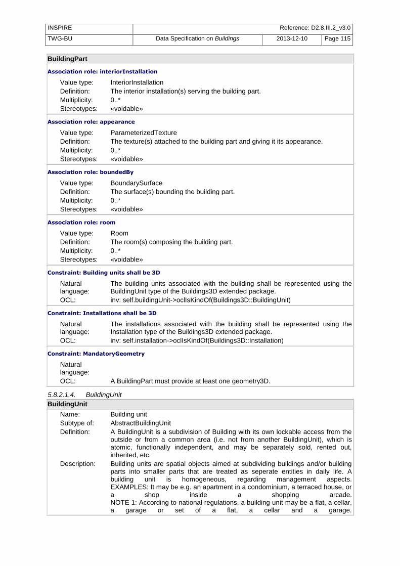
INSPIRE Reference: D2.8.III.2_v3.0
TWG-BU Data Specification on Buildings 2013-12-10 Page 115
BuildingPart
Association role: interiorInstallation
Value type: InteriorInstallation Definition: The interior installation(s) serving the building part. Multiplicity: 0..* Stereotypes: «voidable»
Association role: appearance
Value type: ParameterizedTexture Definition: The texture(s) attached to the building part and giving it its appearance. Multiplicity: 0..* Stereotypes: «voidable»
Association role: boundedBy
Value type: BoundarySurface Definition: The surface(s) bounding the building part. Multiplicity: 0..* Stereotypes: «voidable»
Association role: room
Value type: Room Definition: The room(s) composing the building part. Multiplicity: 0..* Stereotypes: «voidable»
Constraint: Building units shall be 3D
Natural language:
The building units associated with the building shall be represented using the BuildingUnit type of the Buildings3D extended package.
OCL: inv: self.buildingUnit->oclIsKindOf(Buildings3D::BuildingUnit)
Constraint: Installations shall be 3D
Natural language:
The installations associated with the building shall be represented using the Installation type of the Buildings3D extended package.
OCL: inv: self.installation->oclIsKindOf(Buildings3D::Installation)
Constraint: MandatoryGeometry
Natural language:
OCL: A BuildingPart must provide at least one geometry3D.
5.8.2.1.4. BuildingUnit
BuildingUnit
Name: Building unit Subtype of: AbstractBuildingUnit Definition: A BuildingUnit is a subdivision of Building with its own lockable access from the
outside or from a common area (i.e. not from another BuildingUnit), which is atomic, functionally independent, and may be separately sold, rented out, inherited, etc.
Description: Building units are spatial objects aimed at subdividing buildings and/or building parts into smaller parts that are treated as seperate entities in daily life. A building unit is homogeneous, regarding management aspects. EXAMPLES: It may be e.g. an apartment in a condominium, a terraced house, or a shop inside a shopping arcade. NOTE 1: According to national regulations, a building unit may be a flat, a cellar, a garage or set of a flat, a cellar and a garage.

INSPIRE Reference: D2.8.III.2_v3.0
TWG-BU Data Specification on Buildings 2013-12-10 Page 116
BuildingUnit
NOTE 2: According to national regulation, a building that is one entity for daily life (typically, a single family house) may be considered as a Building composed of one BuildingUnit or as a Building composed of zero BuildingUnit.
Stereotypes: «featureType»
Attribute: geometry2D
Name: Geometry 2D Value type: GM_Primitive Definition: 2D or 2.5D geometric representation. Multiplicity: 0..* Stereotypes: «voidable»
Attribute: geometry3D
Name: Geometry 3D Value type: GM_MultiSolid Definition: 3D geometric representation. Multiplicity: 1
Association role: room
Value type: Room Definition: The room(s) composing the building unit. Multiplicity: 0..* Stereotypes: «voidable»
5.8.2.1.5. ClosureSurface
ClosureSurface
Name: ClosureSurface Subtype of: BoundarySurface Definition: ClosureSurfaces are used for buildings which are not enclosed completely, for
example airplane hangars or barns. In order to represent those objects as geometrically closed volume object, the open sides are sealed (virtually closed) by ClosureSurfaces.
Description: NOTE: Those special surfaces are taken into account, when needed to compute volumes and are neglected, when they are irrelevant or not appropriate, for example in visualisations.
Stereotypes: «featureType»
5.8.2.1.6. Door
Door
Name: Door Subtype of: Opening Definition: The doors in the exterior shell of a building or between adjacent rooms. Doors
can be used by people to enter or leave a building or room. Description: NOTE: When using LoD2 or LoD3 of CityGML (as indicated in INSPIRE
Extended3D profile), the feature type Door is limited to the doors in the exterior shell of the building. Source: adapted from City GML.
Stereotypes: «featureType»
5.8.2.1.7. GroundSurface
GroundSurface
Name: GroundSurface Subtype of: BoundarySurface Definition: A spatial object representing the ground plate of a building or building part. The

INSPIRE Reference: D2.8.III.2_v3.0
TWG-BU Data Specification on Buildings 2013-12-10 Page 117
GroundSurface
polygon defining the ground plate is congruent with the building footprint. Description: Source: adapted from City GML Stereotypes: «featureType»
5.8.2.1.8. Installation
Installation
Name: Installation Subtype of: AbstractInstallation Definition: An external construction (of small size) or an external device serving the building
or building part. Description: EXAMPLES: stairway, solar panel, external lift Stereotypes: «featureType»
Attribute: geometry2D
Name: Geometry 2D Value type: GM_Primitive Definition: 2D or 2.5D geometric representation. Multiplicity: 0..* Stereotypes: «voidable»
Attribute: geometry3D
Name: Geometry 3D Value type: GM_Object Definition: 3D geometric representation. Multiplicity: 1
Association role: appearance
Value type: ParameterizedTexture Definition: The texture(s) attached to the installation and giving it its appearance. Multiplicity: 0..* Stereotypes: «voidable»
Association role: boundedBy
Value type: BoundarySurface Definition: The surface(s) bounding the installation. Multiplicity: 0..* Stereotypes: «voidable»
5.8.2.1.9. InteriorInstallation
InteriorInstallation
Name: InteriorInstallation Definition: An internal construction (generally of small size) or an internal device, serving
the building or building part Description: EXAMPLE: stairs, lift Stereotypes: «featureType»
Attribute: inspireId
Name: inspireId Value type: Identifier Definition: External unique object identifier published by the responsible body, which may
be used by external applications to reference the spatial object. Description: NOTE1 External object identifiers are distinct from thematic object identifiers.
NOTE 2 The voidable version identifier attribute is not part of the unique identifier

INSPIRE Reference: D2.8.III.2_v3.0
TWG-BU Data Specification on Buildings 2013-12-10 Page 118
InteriorInstallation
of a spatial object and may be used to distinguish two versions of the same spatial object. NOTE 3 The unique identifier will not change during the life-time of a spatial object.
Multiplicity: 0..1 Stereotypes: «voidable»
Attribute: geometry3D
Name: geometry3D Value type: GM_Object Definition: 3D geometric representation of the internal installation. Multiplicity: 1
Attribute: installationNature
Name: installationNature Value type: InternalInstallationNatureValue Definition: The nature of the internal installation. Multiplicity: 1
Attribute: beginLifespanVersion
Name: beginLifespanVersion Value type: DateTime Definition: Date and time at which this version of the spatial object was inserted or changed
in the spatial data set. Multiplicity: 1 Stereotypes: «voidable,lifeCycleInfo»
Attribute: endLifespanVersion
Name: endLifespanVersion Value type: DateTime Definition: Date and time at which this version of the spatial object was superseded or
retired in the spatial data set. Multiplicity: 0..1 Stereotypes: «voidable,lifeCycleInfo»
5.8.2.1.10. Opening
Opening
Name: Opening Definition: The feature type Opening is the (abstract) base class for semantically describing
openings like doors or windows in outer or inner walls. Openings only exist in models of LoD3 or LoD4.
Description: NOTE: when using LoD3 of CityGML (as indicated in this INSPIRE Extended3D application schema), the spatial object type Opening is limited to the openings in the outer walls of the building Source : adapted from CityGML
Stereotypes: «featureType»
Attribute: inspireId
Name: inspireId Value type: Identifier Definition: External unique object identifier published by the responsible body, which may
be used by external applications to reference the spatial object. Description: NOTE1 External object identifiers are distinct from thematic object identifiers.
NOTE 2 The voidable version identifier attribute is not part of the unique identifier

INSPIRE Reference: D2.8.III.2_v3.0
TWG-BU Data Specification on Buildings 2013-12-10 Page 119
Opening
of a spatial object and may be used to distinguish two versions of the same spatial object. NOTE 3 The unique identifier will not change during the life-time of a spatial object.
Multiplicity: 1
Attribute: geometry3D
Name: geometry3D Value type: BoundaryGeometry3D Definition: 3D geometric representation of the opening (surface embedded in 3D). Multiplicity: 1
Attribute: beginLifespanVersion
Name: beginLifespanVersion Value type: DateTime Definition: Date and time at which this version of the spatial object was inserted or changed
in the spatial data set. Multiplicity: 1 Stereotypes: «voidable,lifeCycleInfo»
Attribute: endLifespanVersion
Name: endLifespanVersion Value type: DateTime Definition: Date and time at which this version of the spatial object was superseded or
retired in the spatial data set. Multiplicity: 0..1 Stereotypes: «voidable,lifeCycleInfo»
5.8.2.1.11. OtherConstruction
OtherConstruction
Name: Other construction Subtype of: AbstractOtherConstruction Definition: An OtherConstruction is a self-standing construction that belongs to theme
Buildings and that is not a Building. Description: NOTE 1: the main difference between a building and an other construction is the
fact that an other construction does not need to be enclosed. NOTE 2: the other constructions to be considered under scope of theme buildings are the constructions that are not present in another INSPIRE theme and that are necessary for environmental use cases, such as the ones considered in this data specification. EXAMPLES: bridge, acoustic fence, city wall.
Stereotypes: «featureType»
Attribute: geometry2D
Name: Geometry 2D Value type: GM_Primitive Definition: 2D or 2.5D geometric representation. Multiplicity: 0..* Stereotypes: «voidable»
Attribute: geometry3D
Name: Geometry 3D Value type: GM_Object Definition: 3D geometric representation.

INSPIRE Reference: D2.8.III.2_v3.0
TWG-BU Data Specification on Buildings 2013-12-10 Page 120
OtherConstruction
Multiplicity: 1
Association role: appearance
Value type: ParameterizedTexture Definition: The texture(s) attached to the other construction and giving it its appearance. Multiplicity: 0..* Stereotypes: «voidable»
Association role: boundedBy
Value type: BoundarySurface Definition: The surface(s) bounding the other construction. Multiplicity: 0..* Stereotypes: «voidable»
5.8.2.1.12. OuterCeilingSurface
OuterCeilingSurface
Name: OuterCeilingSurface Subtype of: BoundarySurface Definition: A surface (feature) belonging to the outer building shell and having the
orientation pointing downwards. Description: EXAMPLES: Visible part of the ceiling of a loggia or of the ceiling of a passage. Stereotypes: «featureType»
5.8.2.1.13. OuterFloorSurface
OuterFloorSurface
Name: OuterFloorSurface Subtype of: BoundarySurface Definition: A surface (feature) belonging to the outer building shell and with the orientation
pointing upwards. Description: EXAMPLES: Visible part of the floor of a passage or of the floor of a loggia. Stereotypes: «featureType»
5.8.2.1.14. ParameterizedTexture
ParameterizedTexture
Name: ParameterizedTexture Definition: Texture representing the appearance aspect of a surface in the exterior shell of
the building. The feature type ParameterizedTexture describes texture that is mapped to a surface (target).
Description: SOURCE: adapted from CityGML. Stereotypes: «featureType»
Attribute: imageURI
Name: imageURI Value type: URI Definition: Uniform Resource Identifier; gives indication where the image used for the
texture may be found. Multiplicity: 1
Attribute: mimeType
Name: mimeType Value type: MimeTypeValue Definition: Format of the image used for texture. Multiplicity: 1

INSPIRE Reference: D2.8.III.2_v3.0
TWG-BU Data Specification on Buildings 2013-12-10 Page 121
ParameterizedTexture
Attribute: textureType
Name: textureType Value type: TextureTypeValue Definition: Type of the texture; gives indication if the texture comes from real-world images
or from standards images in libraries. Multiplicity: 1
5.8.2.1.15. RoofSurface
RoofSurface
Name: RoofSurface Subtype of: BoundarySurface Definition: The surfaces delimiting major roof parts of a building or building part are
expressed by the feature type RoofSurface. Description: Source: adapted from CityGML Stereotypes: «featureType»
Attribute: materialOfRoof
Name: materialOfRoof Value type: MaterialOfRoofValue Definition: Material(s) of the building roof. Multiplicity: 0..* Stereotypes: «voidable»
5.8.2.1.16. Room
Room
Name: Room Definition: A room is any distinguishable space within a structure. Usually, a room is
separated from other spaces by interior walls; moreover, it is separated from outdoor areas by an exterior wall, sometimes with a door.
Stereotypes: «featureType»
Attribute: inspireId
Name: inspireId Value type: Identifier Definition: External unique object identifier published by the responsible body, which may
be used by external applications to reference the spatial object. Description: NOTE1 External object identifiers are distinct from thematic object identifiers.
NOTE 2 The voidable version identifier attribute is not part of the unique identifier of a spatial object and may be used to distinguish two versions of the same spatial object. NOTE 3 The unique identifier will not change during the life-time of a spatial object.
Multiplicity: 0..1 Stereotypes: «voidable»
Attribute: geometry3D
Name: geometry3D Value type: GM_Solid Definition: 3D geometric representation of the room. Multiplicity: 1
Attribute: roomNature
Name: roomNature

INSPIRE Reference: D2.8.III.2_v3.0
TWG-BU Data Specification on Buildings 2013-12-10 Page 122
Room
Value type: RoomNatureValue Definition: The nature (intended use or function) of the room. Multiplicity: 0..1
Attribute: beginLifespanVersion
Name: beginLifespanVersion Value type: DateTime Definition: Date and time at which this version of the spatial object was inserted or changed
in the spatial data set. Multiplicity: 1 Stereotypes: «voidable,lifeCycleInfo»
Attribute: endLifespanVersion
Name: endLifespanVersion Value type: DateTime Definition: Date and time at which this version of the spatial object was superseded or
retired in the spatial data set. Multiplicity: 0..1 Stereotypes: «voidable,lifeCycleInfo»
5.8.2.1.17. WallSurface
WallSurface
Name: WallSurface Subtype of: BoundarySurface Definition: The surfaces that are parts of the building facade visible from the outside. Description: Source: adapted from CityGML. Stereotypes: «featureType»
Attribute: materialOfWall
Name: materialOfWall Value type: MaterialOfFacadeValue Definition: Material(s) of the building exterior walls. Multiplicity: 0..1 Stereotypes: «voidable»
5.8.2.1.18. Window
Window
Name: Window Subtype of: Opening Definition: Windows in the exterior shell of a building, or hatches between adjacent rooms. Description: NOTE 1: The formal difference between the classes window and door is that in
normal cases windows are not specifically intended for the transit of people or vehicles. NOTE 2: when using LoD3 of CityGML (as indicated in INSPIRE Extended3D aplication schema), the feature type Window is limited to the windows in the exterior shell of the building. Source : adapted from CityGML.
Stereotypes: «featureType»
5.8.2.2. Data types
5.8.2.2.1. BoundaryGeometry3D
BoundaryGeometry3D
Name: BoundaryGeometry3D

INSPIRE Reference: D2.8.III.2_v3.0
TWG-BU Data Specification on Buildings 2013-12-10 Page 123
BoundaryGeometry3D
Definition: The information related to the boundary geometry as 3D data. Stereotypes: «dataType»
Attribute: horizontalGeometryEstimatedAccuracyLoD2
Name: horizontalGeometryEstimatedAccuracyLoD2 Value type: Length Definition: The estimated absolute positional accuracy of the (X,Y) coordinates of the LoD2
boundary representation, in the INSPIRE official Coordinate Reference System. Absolute positional accuracy is defined as the mean value of the positional uncertainties for a set of positions where the positional uncertainties are defined as the distance between a measured position and what is considered as the corresponding true position.
Description: NOTE: this mean value may come from quality measures on a homogeneous population of buildings or from an estimation based on the knowledge of the production processes and of their accuracy.
Multiplicity: 0..1 Stereotypes: «voidable»
Attribute: horizontalGeometryEstimatedAccuracyLoD3
Name: horizontalGeometryEstimatedAccuracyLoD3 Value type: Length Definition: The estimated absolute positional accuracy of the (X,Y) coordinates of the LoD3
boundary representation, in the INSPIRE official Coordinate Reference System. Absolute positional accuracy is defined as the mean value of the positional uncertainties for a set of positions where the positional uncertainties are defined as the distance between a measured position and what is considered as the corresponding true position.
Description: NOTE: this mean value may come from quality measures on a homogeneous population of buildings or from an estimation based on the knowledge of the production processes and of their accuracy.
Multiplicity: 0..1 Stereotypes: «voidable»
Attribute: horizontalGeometryEstimatedAccuracyLoD4
Name: horizontalGeometryEstimatedAccuracyLoD4 Value type: Length Definition: The estimated absolute positional accuracy of the (X,Y) coordinates of the LoD4
boundary representation, in the INSPIRE official Coordinate Reference System. Absolute positional accuracy is defined as the mean value of the positional uncertainties for a set of positions where the positional uncertainties are defined as the distance between a measured position and what is considered as the corresponding true position.
Description: NOTE: this mean value may come from quality measures on a homogeneous population of buildings or from an estimation based on the knowledge of the production processes and of their accuracy.
Multiplicity: 0..1 Stereotypes: «voidable»
Attribute: LoD2MultiSurface
Name: LoD2MultiSurface Value type: GM_MultiSurface Definition: The geometry of the boundary, corresponding to the LoD2 of CityGML. Description: LoD2 of City GML implies generalised geometry with vertical walls and simple
roof shapes. Multiplicity: 0..1

INSPIRE Reference: D2.8.III.2_v3.0
TWG-BU Data Specification on Buildings 2013-12-10 Page 124
BoundaryGeometry3D
Attribute: LoD3MultiSurface
Name: LoD3MultiSurface Value type: GM_MultiSurface Definition: The geometry of the boundary, corresponding to the LoD3 of CityGML. Description: LoD3 of City GML represents the exact geometry of the building, approximating
its true shape. Multiplicity: 0..1
Attribute: LoD4MultiSurface
Name: LoD4MultiSurface Value type: GM_MultiSurface Definition: The geometry of the boundary, corresponding to the LoD4 of CityGML. Description: LoD4 of City GML represents the accurate geometry of the building,
approximating its true shape. Multiplicity: 0..1
Attribute: verticalGeometryEstimatedAccuracyLoD2
Name: verticalGeometryEstimatedAccuracyLoD2 Value type: Length Definition: The estimated absolute positional accuracy of the Z coordinate of the LoD2
boundary representation, in the INSPIRE official Coordinate Reference System. Absolute positional accuracy is defined as the mean value of the positional uncertainties for a set of positions where the positional uncertainties are defined as the distance between a measured position and what is considered as the corresponding true position. -- NOTE:This mean value may come from quality measures on a homogeneous population of buildings or from an estimation based on the knowledge of the production processes and of their accuracy.
Multiplicity: 0..1 Stereotypes: «voidable»
Attribute: verticalGeometryEstimatedAccuracyLoD3
Name: verticalGeometryEstimatedAccuracyLoD3 Value type: Length Definition: The estimated absolute positional accuracy of the Z coordinate of the LoD3
boundary representation, in the INSPIRE official Coordinate Reference System. Absolute positional accuracy is defined as the mean value of the positional uncertainties for a set of positions where the positional uncertainties are defined as the distance between a measured position and what is considered as the corresponding true position.
Description: NOTE:This mean value may come from quality measures on a homogeneous population of buildings or from an estimation based on the knowledge of the production processes and of their accuracy.
Multiplicity: 0..1 Stereotypes: «voidable»
Attribute: verticalGeometryEstimatedAccuracyLoD4
Name: verticalGeometryEstimatedAccuracyLoD4 Value type: Length Definition: The estimated absolute positional accuracy of the Z coordinate of the LoD4
boundary representation, in the INSPIRE official Coordinate Reference System. Absolute positional accuracy is defined as the mean value of the positional uncertainties for a set of positions where the positional uncertainties are defined as the distance between a measured position and what is considered as the corresponding true position.

INSPIRE Reference: D2.8.III.2_v3.0
TWG-BU Data Specification on Buildings 2013-12-10 Page 125
BoundaryGeometry3D
Description: NOTE:This mean value may come from quality measures on a homogeneous population of buildings or from an estimation based on the knowledge of the production processes and of their accuracy.
Multiplicity: 0..1 Stereotypes: «voidable»
Constraint: atLeastOneMandatoryGeometry
Natural language:
OCL: At least one of the mandatory geometries must be provided:
5.8.2.2.2. TextCoordGen
TextCoordGen
Name: TextCoordGen Subtype of: TextureParametrization Definition: Way to map a texture file (2D image coordinates) to a surface of the exterior
shell of a building (3D real-world coordinates), by applying a transformation between the two coordinate reference systems.
Stereotypes: «dataType»
Attribute: worldToTexture
Name: worldToTexture Value type: TransformationMatrix3x4 Definition: Matrix of the transformation between the file coordinates in an image to the
geographical coordinates. Multiplicity: 1
5.8.2.2.3. TextCoordList
TextCoordList
Name: TextCoordList Subtype of: TextureParametrization Definition: Way to map a texture file to a surface of the exterior shell of a building, by
explicitly relating the coordinates of the image to the corresponding coordinates on the surface in the building shell.
Stereotypes: «dataType»
Attribute: ring
Name: ring Value type: URI Definition: Uniform Resource Identifier; gives indication where the ring (limit of image) may
be found. Multiplicity: 1
Attribute: textureCoordinates
Name: textureCoordinates Value type: Number Definition: List of coordinates in the texture file. Multiplicity: 0..*
5.8.2.2.4. TextureParametrization
TextureParametrization (abstract)
Name: TextureParametrization Definition: TextureParametrization is the abstract supertype of TextCoordGen and
TextCoordList. Is is used to relate both to a ParametrizedTexture.

INSPIRE Reference: D2.8.III.2_v3.0
TWG-BU Data Specification on Buildings 2013-12-10 Page 126
TextureParametrization (abstract)
Stereotypes: «dataType»
Association role: texture
Value type: ParameterizedTexture Definition: The texture to be applied to the spatial object. Multiplicity: 0..*
5.8.2.2.5. TransformationMatrix3x4
TransformationMatrix3x4
Name: TransformationMatrix3x4 Definition: A matrix providing the transformation function between coordinates of the texture
image and the geographical coordinates. Stereotypes: «dataType»
Attribute: elements
Name: elements Value type: Number Definition: The matrix elements. Multiplicity: 0..*
5.8.2.3. Code lists
5.8.2.3.1. InternalInstallationNatureValue
InternalInstallationNatureValue
Name: InternalInstallationNatureValue Definition: Code list for the possible values of the nature of an internal installation. Extensibility: open Identifier: http://inspire.ec.europa.eu/codelist/InternalInstallationNatureValue Values: The allowed values for this code list comprise the values specified in Annex C
and additional values at any level defined by data providers. Annex C includes recommended values that may be used by data providers.
5.8.2.3.2. MimeTypeValue
MimeTypeValue
Name: MimeTypeValue Definition: Mime types code list. Extensibility: open Identifier: http://inspire.ec.europa.eu/codelist/MimeTypeValue Values: The allowed values for this code list comprise the values specified in Annex C
and additional values at any level defined by data providers. Annex C includes recommended values that may be used by data providers.
5.8.2.3.3. RoomNatureValue
RoomNatureValue
Name: RoomNatureValue Definition: Code list giving the possible values for the nature of a room (use or intended
function). Extensibility: open Identifier: http://inspire.ec.europa.eu/codelist/RoomNatureValue Values: The allowed values for this code list comprise the values specified in Annex C
and additional values at any level defined by data providers. Annex C includes recommended values that may be used by data providers.

INSPIRE Reference: D2.8.III.2_v3.0
TWG-BU Data Specification on Buildings 2013-12-10 Page 127
5.8.2.3.4. TextureTypeValue
TextureTypeValue
Name: TextureTypeValue Definition: The texture type code list. Extensibility: open Identifier: http://inspire.ec.europa.eu/codelist/TextureTypeValue Values: The allowed values for this code list comprise the values specified in Annex C
and additional values at any level defined by data providers. Annex C includes recommended values that may be used by data providers.
5.8.2.4. Imported types (informative)
This section lists definitions for feature types, data types and enumerations and code lists that are defined in other application schemas. The section is purely informative and should help the reader understand the feature catalogue presented in the previous sections. For the normative documentation of these types, see the given references.
5.8.2.4.1. AbstractBuildingUnit
AbstractBuildingUnit (abstract)
Package: BuildingsExtendedBase Reference: INSPIRE Data specification on Buildings [DS-D2.8.III.2] Definition: Abstract spatial object type grouping the semantic properties of building units. A
BuildingUnit is a subdivision of Building with its own lockable access from the outside or from a common area (i.e. not from another BuildingUnit), which is atomic, functionally independent, and may be separately sold, rented out, inherited, etc.
Description: Building units are spatial objects aimed at subdividing buildings and/or building parts into smaller parts that are treated as seperate entities in daily life. A building unit is homogeneous, regarding management aspects. EXAMPLES: It may be e.g. an apartment in a condominium, a terraced house, or a shop inside a shopping arcade. NOTE 1: According to national regulations, a building unit may be a flat, a cellar, a garage or set of a flat, a cellar and a garage. NOTE 2: According to national regulation, a building that is one entity for daily life (typically, a single family house) may be considered as a Building composed of one BuildingUnit or as a Building composed of zero BuildingUnit.
5.8.2.4.2. AbstractInstallation
AbstractInstallation (abstract)
Package: BuildingsExtendedBase Reference: INSPIRE Data specification on Buildings [DS-D2.8.III.2] Definition: Abstract spatial object type grouping the semantic properties of installations. An
external construction (of small size) or an external device serving the building or building part.
Description: EXAMPLES: stairway, solar panel, external lift
5.8.2.4.3. AbstractOtherConstruction
AbstractOtherConstruction (abstract)
Package: BuildingsExtendedBase Reference: INSPIRE Data specification on Buildings [DS-D2.8.III.2] Definition: Abstract spatial object type grouping the semantic properties of other
constructions. An other construction is a self-standing construction that belongs to theme Buildings and that is not a Building.
Description: NOTE 1: the main difference between a building and an other construction is the fact that an other construction does not need to be enclosed. NOTE 2: the other constructions to be considered under scope of theme Buildings are the constructions that are not present in another INSPIRE theme

INSPIRE Reference: D2.8.III.2_v3.0
TWG-BU Data Specification on Buildings 2013-12-10 Page 128
AbstractOtherConstruction (abstract)
and that are necessary for environmental use cases, such as the ones considered in this data specification. EXAMPLES: bridge, acoustic fence, city wall.
5.8.2.4.4. BuildingInfo
BuildingInfo (abstract)
Package: BuildingsExtendedBase Reference: INSPIRE Data specification on Buildings [DS-D2.8.III.2] Definition: Abstract spatial object type grouping the additional specific properties of Building
and Building Part. Description: NOTE 1: The additonal properties are those that are not already included in the
base application schema. NOTE 2: The specific properties are the properties that appliy to Building and BuildingPart without applying to BuildingUnit.
5.8.2.4.5. DateTime
DateTime
Package: Date and Time Reference: Geographic information -- Conceptual schema language [ISO/TS 19103:2005]
5.8.2.4.6. GM_MultiSolid
GM_MultiSolid
Package: Geometric aggregates Reference: Geographic information -- Spatial schema [ISO 19107:2003]
5.8.2.4.7. GM_MultiSurface
GM_MultiSurface
Package: Geometric aggregates Reference: Geographic information -- Spatial schema [ISO 19107:2003]
5.8.2.4.8. GM_Object
GM_Object (abstract)
Package: Geometry root Reference: Geographic information -- Spatial schema [ISO 19107:2003]
5.8.2.4.9. GM_Primitive
GM_Primitive (abstract)
Package: Geometric primitive Reference: Geographic information -- Spatial schema [ISO 19107:2003]
5.8.2.4.10. GM_Solid
GM_Solid
Package: Geometric primitive Reference: Geographic information -- Spatial schema [ISO 19107:2003]
5.8.2.4.11. Identifier
Identifier
Package: Base Types Reference: INSPIRE Generic Conceptual Model, version 3.4 [DS-D2.5] Definition: External unique object identifier published by the responsible body, which may
be used by external applications to reference the spatial object. Description: NOTE1 External object identifiers are distinct from thematic object identifiers.
NOTE 2 The voidable version identifier attribute is not part of the unique identifier

INSPIRE Reference: D2.8.III.2_v3.0
TWG-BU Data Specification on Buildings 2013-12-10 Page 129
Identifier
of a spatial object and may be used to distinguish two versions of the same spatial object. NOTE 3 The unique identifier will not change during the life-time of a spatial object.
5.8.2.4.12. Length
Length
Package: Units of Measure Reference: Geographic information -- Conceptual schema language [ISO/TS 19103:2005]
5.8.2.4.13. MaterialOfFacadeValue
MaterialOfFacadeValue
Package: BuildingsExtendedBase Reference: INSPIRE Data specification on Buildings [DS-D2.8.III.2] Definition: Code list for the possible values of MaterialOfFacade
5.8.2.4.14. MaterialOfRoofValue
MaterialOfRoofValue
Package: BuildingsExtendedBase Reference: INSPIRE Data specification on Buildings [DS-D2.8.III.2] Definition: Code list for possible values of attribute MaterialOfRoof
5.8.2.4.15. Number
Number (abstract)
Package: Numerics Reference: Geographic information -- Conceptual schema language [ISO/TS 19103:2005]
5.8.2.4.16. URI
URI
Package: basicTypes Reference: Geographic information -- Geography Markup Language (GML) [ISO
19136:2007]

INSPIRE Reference: D2.8.III.2_v3.0
TWG-BU Data Specification on Buildings 2013-12-10 Page 130
6 Reference systems, units of measure and grids
6.1 Default reference systems, units of measure and grid The reference systems, units of measure and geographic grid systems included in this sub-section are the defaults to be used for all INSPIRE data sets, unless theme-specific exceptions and/or additional requirements are defined in section 6.2.
6.1.1 Coordinate reference systems
6.1.1.1. Datum
IR Requirement Annex II, Section 1.2
Datum for three-dimensional and two-dimensional coordinate reference systems
For the three-dimensional and two-dimensional coordinate reference systems and the horizontal component of compound coordinate reference systems used for making spatial data sets available, the datum shall be the datum of the European Terrestrial Reference System 1989 (ETRS89) in areas within its geographical scope, or the datum of the International Terrestrial Reference System (ITRS) or other geodetic coordinate reference systems compliant with ITRS in areas that are outside the geographical scope of ETRS89. Compliant with the ITRS means that the system definition is based on the definition of the ITRS and there is a well documented relationship
between both systems, according to EN ISO 19111.
6.1.1.2. Coordinate reference systems
IR Requirement Annex II, Section 1.3
Coordinate Reference Systems
Spatial data sets shall be made available using at least one of the coordinate reference systems specified in sections 1.3.1, 1.3.2 and 1.3.3, unless one of the conditions specified in section 1.3.4 holds. 1.3.1. Three-dimensional Coordinate Reference Systems – Three-dimensional Cartesian coordinates based on a datum specified in 1.2 and using the
parameters of the Geodetic Reference System 1980 (GRS80) ellipsoid. – Three-dimensional geodetic coordinates (latitude, longitude and ellipsoidal height) based on a
datum specified in 1.2 and using the parameters of the GRS80 ellipsoid. 1.3.2. Two-dimensional Coordinate Reference Systems – Two-dimensional geodetic coordinates (latitude and longitude) based on a datum specified in
1.2 and using the parameters of the GRS80 ellipsoid. – Plane coordinates using the ETRS89 Lambert Azimuthal Equal Area coordinate reference
system. – Plane coordinates using the ETRS89 Lambert Conformal Conic coordinate reference system. – Plane coordinates using the ETRS89 Transverse Mercator coordinate reference system.

INSPIRE Reference: D2.8.III.2_v3.0
TWG-BU Data Specification on Buildings 2013-12-10 Page 131
1.3.3. Compound Coordinate Reference Systems 1. For the horizontal component of the compound coordinate reference system, one of the
coordinate reference systems specified in section 1.3.2 shall be used. 2. For the vertical component, one of the following coordinate reference systems shall be used: – For the vertical component on land, the European Vertical Reference System (EVRS) shall be
used to express gravity-related heights within its geographical scope. Other vertical reference systems related to the Earth gravity field shall be used to express gravity-related heights in areas that are outside the geographical scope of EVRS.
– For the vertical component in the free atmosphere, barometric pressure, converted to height using ISO 2533:1975 International Standard Atmosphere, or other linear or parametric reference systems shall be used. Where other parametric reference systems are used, these shall be described in an accessible reference using EN ISO 19111-2:2012.
– For the vertical component in marine areas where there is an appreciable tidal range (tidal waters), the Lowest Astronomical Tide (LAT) shall be used as the reference surface.
– For the vertical component in marine areas without an appreciable tidal range, in open oceans and effectively in waters that are deeper than 200 meters, the Mean Sea Level (MSL) or a well-defined reference level close to the MSL shall be used as the reference surface.
1.3.4. Other Coordinate Reference Systems Exceptions, where other coordinate reference systems than those listed in 1.3.1, 1.3.2 or 1.3.3 may be used, are: 1. Other coordinate reference systems may be specified for specific spatial data themes in this
Annex. 2. For regions outside of continental Europe, Member States may define suitable coordinate
reference systems. The geodetic codes and parameters needed to describe these coordinate reference systems and to allow conversion and transformation operations shall be documented and an identifier shall be
created, according to EN ISO 19111 and ISO 19127.
6.1.1.3. Display
IR Requirement Annex II, Section 1.4
Coordinate Reference Systems used in the View Network Service For the display of spatial data sets with the view network service as specified in Regulation No 976/2009, at least the coordinate reference systems for two-dimensional geodetic coordinates
(latitude, longitude) shall be available.
6.1.1.4. Identifiers for coordinate reference systems
IR Requirement Annex II, Section 1.4
Coordinate Reference Systems used in the View Network Service 1. Coordinate reference system parameters and identifiers shall be managed in one or several
common registers for coordinate reference systems. 2. Only identifiers contained in a common register shall be used for referring to the coordinate
reference systems listed in this Section.

INSPIRE Reference: D2.8.III.2_v3.0
TWG-BU Data Specification on Buildings 2013-12-10 Page 132
These Technical Guidelines propose to use the http URIs provided by the Open Geospatial Consortium as coordinate reference system identifiers (see identifiers for the default CRSs below). These are based on and redirect to the definition in the EPSG Geodetic Parameter Registry (http://www.epsg-registry.org/).
TG Requirement 2 The identifiers listed in Table 5 shall be used for referring to the coordinate reference systems used in a data set.
NOTE CRS identifiers may be used e.g. in: – data encoding, – data set and service metadata, and – requests to INSPIRE network services.
Table 5. http URIs for the default coordinate reference systems
Coordinate reference system Short name http URI identifier
3D Cartesian in ETRS89 ETRS89-XYZ http://www.opengis.net/def/crs/EPSG/0/4936
3D geodetic in ETRS89 on GRS80 ETRS89-GRS80h http://www.opengis.net/def/crs/EPSG/0/4937
2D geodetic in ETRS89 on GRS80 ETRS89-GRS80 http://www.opengis.net/def/crs/EPSG/0/4258
2D LAEA projection in ETRS89 on GRS80
ETRS89-LAEA http://www.opengis.net/def/crs/EPSG/0/3035
2D LCC projection in ETRS89 on GRS80
ETRS89-LCC http://www.opengis.net/def/crs/EPSG/0/3034
2D TM projection in ETRS89 on GRS80, zone 26N (30°W to 24°W)
ETRS89-TM26N http://www.opengis.net/def/crs/EPSG/0/3038
2D TM projection in ETRS89 on GRS80, zone 27N (24°W to 18°W)
ETRS89-TM27N http://www.opengis.net/def/crs/EPSG/0/3039
2D TM projection in ETRS89 on GRS80, zone 28N (18°W to 12°W)
ETRS89-TM28N http://www.opengis.net/def/crs/EPSG/0/3040
2D TM projection in ETRS89 on GRS80, zone 29N (12°W to 6°W)
ETRS89-TM29N http://www.opengis.net/def/crs/EPSG/0/3041
2D TM projection in ETRS89 on GRS80, zone 30N (6°W to 0°)
ETRS89-TM30N http://www.opengis.net/def/crs/EPSG/0/3042
2D TM projection in ETRS89 on GRS80, zone 31N (0° to 6°E)
ETRS89-TM31N http://www.opengis.net/def/crs/EPSG/0/3043
2D TM projection in ETRS89 on GRS80, zone 32N (6°E to 12°E)
ETRS89-TM32N http://www.opengis.net/def/crs/EPSG/0/3044
2D TM projection in ETRS89 on GRS80, zone 33N (12°E to 18°E)
ETRS89-TM33N http://www.opengis.net/def/crs/EPSG/0/3045
2D TM projection in ETRS89 on GRS80, zone 34N (18°E to 24°E)
ETRS89-TM34N http://www.opengis.net/def/crs/EPSG/0/3046
2D TM projection in ETRS89 on GRS80, zone 35N (24°E to 30°E)
ETRS89-TM35N http://www.opengis.net/def/crs/EPSG/0/3047
2D TM projection in ETRS89 on GRS80, zone 36N (30°E to 36°E)
ETRS89-TM36N http://www.opengis.net/def/crs/EPSG/0/3048
2D TM projection in ETRS89 on GRS80, zone 37N (36°E to 42°E)
ETRS89-TM37N http://www.opengis.net/def/crs/EPSG/0/3049
2D TM projection in ETRS89 on GRS80, zone 38N (42°E to 48°E)
ETRS89-TM38N http://www.opengis.net/def/crs/EPSG/0/3050
2D TM projection in ETRS89 on GRS80, zone 39N (48°E to 54°E)
ETRS89-TM39N http://www.opengis.net/def/crs/EPSG/0/3051
Height in EVRS EVRS http://www.opengis.net/def/crs/EPSG/0/5730
3D compound: 2D geodetic in ETRS89 on GRS80, and EVRS height
ETRS89-GRS80-EVRS
http://www.opengis.net/def/crs/EPSG/0/7409
6.1.2 Temporal reference system

INSPIRE Reference: D2.8.III.2_v3.0
TWG-BU Data Specification on Buildings 2013-12-10 Page 133
IR Requirement Article 11
Temporal Reference Systems 1. The default temporal reference system referred to in point 5 of part B of the Annex to
Commission Regulation (EC) No 1205/2008 (14
) shall be used, unless other temporal reference
systems are specified for a specific spatial data theme in Annex II.
NOTE 1 Point 5 of part B of the Annex to Commission Regulation (EC) No 1205/2008 (the INSPIRE Metadata IRs) states that the default reference system shall be the Gregorian calendar, with dates expressed in accordance with ISO 8601. NOTE 2 ISO 8601 Data elements and interchange formats – Information interchange – Representation of dates and times is an international standard covering the exchange of date and time-related data. The purpose of this standard is to provide an unambiguous and well-defined method of representing dates and times, so as to avoid misinterpretation of numeric representations of dates and times, particularly when data is transferred between countries with different conventions for writing numeric dates and times. The standard organizes the data so the largest temporal term (the year) appears first in the data string and progresses to the smallest term (the second). It also provides for a standardized method of communicating time-based information across time zones by attaching an offset to Coordinated Universal Time (UTC). EXAMPLE 1997 (the year 1997), 1997-07-16 (16
th July 1997), 1997-07-16T19:20:30+01:00 (16
th
July 1997, 19h 20‘ 30‘‘, time zone: UTC+1)
6.1.3 Units of measure
IR Requirement Article 12
Other Requirements & Rules (…) 2. All measurement values shall be expressed using SI units or non-SI units accepted for use with
the International System of Units, unless specified otherwise for a specific spatial data theme or
type.
6.2 Theme-specific requirements and recommendations
6.2.1 Coordinate reference systems
o it is not recommended to use ETRS89-XYZ for Cartesian coordinates in ETRS89, because the (X, Y, Z) coordinates used by this system are not the relevant ones to make meaningful distinction between 2D, 2,5D and 3D data
o theme Building being used at large scale, projections offering little linear alteration should be
preferred : - ETRS89-LAEA for ETRS89 coordinates projected into plane coordinates by the Lambert
Azimuthal Equal Area projection
14
OJ L 326, 4.12.2008, p. 12.
INSPIRE Reference: D2.8.III.2_v3.0
TWG-BU Data Specification on Buildings 2013-12-10 Page 134
- ETRS89-TMzn for ETRS89 coordinates projected into plane coordinates by the Transverse Mercator projection
Recommendation 2 For 2D data, the two-dimensional Coordinate Reference Systems defined by theme RS should be used.
Recommendation 3 For 2,5D and 3D data, the Compound Coordinate Reference Systems should be used preferably to the three-dimensional Coordinate Reference Systems.
Some vertical coordinate reference systems are obviously not relevant for theme Buildings. It is the case of the vertical reference systems that are not gravity related: - LAT for depth of the sea floor, where there is an appreciable tidal range - MSL for depth of the sea floor, in marine areas without an appreciable tidal range, in open oceans
and effectively in waters that are deeper than 200m - ISA for pressure coordinate in the free atmosphere - PFO for Pressure coordinate in the free ocean
Recommendation 4 Only gravity-related vertical coordinate reference systems should be used for theme Buildings.
6.2.2 Units of measure NOTE: Units of measure from International System shall be used for theme Buildings. Regarding values of attributes, the related requirements are expressed as constraints in the applications schemas.

INSPIRE Reference: D2.8.III.2_v3.0
TWG-BU Data Specification on Buildings 2013-12-10 Page 135
7 Data quality This chapter includes a description of the data quality elements and sub-elements as well as the corresponding data quality measures that should be used to evaluate and document data quality for data sets related to the spatial data theme Buildings (section 7.1). It may also define requirements or recommendations about the targeted data quality results applicable for data sets related to the spatial data theme Buildings (sections 0 and 7.3). In particular, the data quality elements, sub-elements and measures specified in section 7.1 should be used for
evaluating and documenting data quality properties and constraints of spatial objects, where such properties or constraints are defined as part of the application schema(s) (see section 5);
evaluating and documenting data quality metadata elements of spatial data sets (see section 8); and/or
specifying requirements or recommendations about the targeted data quality results applicable for data sets related to the spatial data theme Buildings (see sections 0 and 7.3).
The descriptions of the elements and measures are based on Annex D of ISO/DIS 19157 Geographic information – Data quality.
7.1 Data quality elements Table 6 lists all data quality elements and sub-elements that are being used in this specification. Data quality information can be evaluated at level of spatial object, spatial object type, dataset or dataset series. The level at which the evaluation is performed is given in the ―Evaluation Scope‖ column. The measures to be used for each of the listed data quality sub-elements are defined in the following sub-sections.
Table 6 – Data quality elements used in the spatial data theme Buildings
Section Data quality element
Data quality sub-element
Definition Evaluation Scope
7.1.1 Completeness Commission excess data present in the dataset, as described by the scope
spatial object type
7.1.2 Completeness Omission data absent from the dataset, as described by the scope
spatial object type
7.1.3 Positional accuracy
Absolute or external accuracy
closeness of reported coordinate values to values accepted as or being true
spatial object type
7.1.4 Usability -- degree of adherence of a dataset to a specific set of requirements
dataset
Recommendation 12 Where it is impossible to express the evaluation of a data quality element in a quantitative way, the evaluation of the element should be expressed with a textual statement as a data quality descriptive result.
7.1.1 Completeness – Commission

INSPIRE Reference: D2.8.III.2_v3.0
TWG-BU Data Specification on Buildings 2013-12-10 Page 136
Recommendation 13 Commission should be evaluated and documented using <error rate, from ISO/DIS 19157> as specified in the tables below.
NOTE: this recommendation applies to any data set related to theme Buildings, whatever profile is used. In case an extended profile is used, priority should be given to report omission related to feature types Building and BuildingPart.
Name Rate of excess items
Alternative name –
Data quality element Completeness
Data quality sub-element Commission
Data quality basic measure Error rate
Definition Number of excess items in the dataset in relation to the number of items that should have been present.
Description Items that should have been present are defined in the data capture rules of the data producer that have to be documented, e.g. in the template for additional information (provided in annex D)
Evaluation scope Data set
Reporting scope Data set
Parameter
Data quality value type Real (e.g. percentage, ratio)
Data quality value structure Single value
Source reference ISO/DIS 19157 Geographic information – Data quality
Example 2% (The dataset has 2% building parts more than the ones necessary to model the universe of discourse)
Measure identifier 3 (ISO/DIS 19157:2012)
7.1.2 Completeness – Omission
Recommendation 14 Omission should be evaluated and documented using <error rate, from ISO/DIS 19157> as specified in the tables below.
NOTE: this recommendation applies to any data set related to theme Buildings, whatever profile is used. In case an extended profile is used, priority should be given to report omission related to feature types Building and BuildingPart.
Name Rate of missing items
Alternative name –
Data quality element Completeness
Data quality sub-element Omission
Data quality basic measure Error rate
Definition Number of missing items in the dataset in relation to the number of items that should have been present.
Description Items that should have been present are defined in the data capture rules of the data producer that have to be documented, e.g. in the template for additional information (provided in annex E)
Evaluation scope Data set
Reporting scope Data set
Parameter –
Data quality value type Real (e.g. percentage, ratio)
Data quality value structure Single value
Source reference ISO/DIS 19157 Geographic information – Data quality
Example 5% (The dataset has 5% less buildings than the ones necessary to model the universe of discourse)

INSPIRE Reference: D2.8.III.2_v3.0
TWG-BU Data Specification on Buildings 2013-12-10 Page 137
Measure identifier 7 (ISO/DIS 19157:2012)
7.1.3 Positional accuracy – Absolute or external accuracy
Recommendation 15 Absolute or external accuracy should be evaluated and documented using <Name of the measure(s), from ISO/DIS 19157> as specified in the tables below.
NOTE: this recommendation applies to any data set related to theme Buildings, whatever profile is used.
Name Root mean square error of planimetry
Alternative name RMSEP
Data quality element Positional accuracy
Data quality sub-element Absolute or external accuracy
Data quality basic measure Not applicable
Definition Radius of a circle around the given point, in which the true value lies with probability P
Description The true values of the observed coordinates X and Y are known as xt and yt .
From this the estimator
yields to the linear root mean square error of planimetry
RMSEP =
Evaluation scope data set;
Reporting scope data set
Parameter -
Data quality value type Measure
Data quality value structure Single value
Source reference ISO/DIS 19157 Geographic information – Data quality
Example -
Measure identifier 47 (ISO/DIS 19157:2012)
Recommendation 16 Absolute or external accuracy of the vertical component of feature types, should be evaluated and documented using Root mean square error as
specified in the table below.
NOTE: this recommendation applies to only to data sets related to theme Buildings and having vertical component, i.e. to data sets with 3D or 2,5D data.
Name Root mean square error
Alternative name RMSE
Data quality element Positional accuracy
Data quality sub-element Absolute or external accuracy
Data quality basic measure Not applicable
Definition Standard deviation, where the true value is not estimated from the observations but known a priori
Description The true value of an observable Z is known as zt . From this, the
estimator:

INSPIRE Reference: D2.8.III.2_v3.0
TWG-BU Data Specification on Buildings 2013-12-10 Page 138
yields to the linear root mean square error RMSE = z.
Evaluation scope data set
Reporting scope data set
Parameter -
Data quality value type Measure
Data quality value structure Single value
Source reference ISO/DIS 19157 Geographic information – Data quality
Example -
Measure identifier 39 (ISO/DIS 19157:2012)
7.1.4 Usability
Recommendation 17 Usability should be evaluated and documented using < Computation of population use case pass, Assessment of vulnerability to earthquake use case conformance> as specified in the tables below.
NOTE: this recommendation applies to any data set related to theme Buildings, whatever profile is used.
Name < Computation of population use case pass, >
Alternative name
Data quality element usability element
Data quality sub-element
Data quality basic measure correctness indicator
Definition indication that all the requirements for computation of population are fulfilled
Description R1: completeness for the buildings whose current use is residential, industrial or commerceAndServices must be better than 90%
R2: at least, 95 % of the buildings of interest must be represented by a GM_Surface
R3: the completeness and thematic accuracy on attribute numberOfFloorAboveGround must be better than 90% or the
completeness and thematic accuracy on attribute heightAboveGround must be better than 90%
R4: the completeness and thematic accuracy on attribute currentUse must be better than 90%
R5: positional geometric accuracy on buildings must be better than 5 m.
Evaluation scope data set
Reporting scope data set
Parameter
Data quality value type Boolean (true if the requirements R1 to R5 are fulfilled)
Data quality value structure Single value
Source reference
Example
Measure identifier

INSPIRE Reference: D2.8.III.2_v3.0
TWG-BU Data Specification on Buildings 2013-12-10 Page 139
Name < Assessment of vulnerability to earthquake use case conformance>
Alternative name
Data quality element usability element
Data quality sub-element
Data quality basic measure correctness indicator
Definition indication that all the requirements for assessing vulnerability to earthquake are fulfilled
Description R1: completeness for the buildings having currentUse in real world should
be better than 90%
R2: at least, 95 % of the buildings must be represented by a GM_Surface
R3: the completeness and thematic accuracy on attribute numberOfFloorAboveGround must be better than 90% or the
completeness and thematic accuracy on attribute heightAboveGround must be better than 90%
R4: the date of construction must be available with resolution equivalent or better than 5 years for the buildings constructed after 1970, 10 years for
buildings constructed between 1950 and 1970 , 20 years between 1930 and 1950, for at least 90% of buildings
R5: the completeness and thematic accuracy on attribute material of structure must be better than 90%
Evaluation scope data set
Reporting scope data set
Parameter
Data quality value type A (if requirements R1 to R5 are fulfilled) B (if requirements R1 to R4 are fulfilled)
Data quality value structure single
Source reference
Example
Measure identifier
7.2 Minimum data quality requirements No minimum data quality requirements are defined for the spatial data theme Buildings.
7.3 Recommendation on data quality Data related to theme Buildings may be provided according several levels of detail. The level of detail has to be adapted to the use case(s). The level of detail of a building data set is characterised both by the choice of the represented features and by the geometric representation of these features (mainly the positional accuracy). For instance, a data set with only buildings will not be used at the same range of scales as a data set with buildings and some of its constitutive elements (building part, building unit, walls, roofs, rooms …).

INSPIRE Reference: D2.8.III.2_v3.0
TWG-BU Data Specification on Buildings 2013-12-10 Page 140
Figure 59: The scale range suitable for the feature types of theme Buildings
The level of detail of a building data set has to be consistent, i.e. the positional accuracy of the geometric representation has to be adapted to the scale range of the feature types the data set contains. The following Table 7 gives the recommended minimum scale and accuracy for the various possible levels of detail of building data.
Table 7: Recommended minimum scale and accuracy for building data sets.
LoD 0 (2D) LoD1 (3D)
LoD 0 (2D) LoD1 (3D)
LoD 2
LoD2 (2D) LoD2 (3D)
Feature types
Building Building BuildingPart
Building BuildingPart Installation
Building BuildingPart Installation
BoundarySurface
Scale 1/25 000 1/10 000 1/5 000 1/5 000
Accuracy 5 m 2 m 1 m 1 m
LoD 3 LoD4
LoD 3 (3D) Lod4 (2D) LoD4 (3D)
Feature types Building BuildingPart Installation
BoundarySurface Openings
Building BuildingPart Installation
BuildingUnit
Building BuildingPart Installation
BoundarySurface Opening BuildingUnit – Room
InternalBuildingInstallation
Scale 1/2 500 1/1 000 1/1 000
Accuracy 0,5 m 0,2 m 0,2 m
Recommendation 5 A data set related to INSPIRE theme Buildings should have the minimum
positional accuracy indicated in table n°2 above.

INSPIRE Reference: D2.8.III.2_v3.0
TWG-BU Data Specification on Buildings 2013-12-10 Page 141
NOTE: the recommendation must be understood as follows: - a data set containing only feature type Building should have an absolute positional accuracy
equal or better than 5 m - a data set containing only feature types Building and BuildingPart should have an absolute
positional accuracy equal or better than 2 m - a data set corresponding to LoD2 should have an accuracy better than 1 m. A data set is
considered of LoD2 if it contains at least one feature type typical of LoD2 and no feature type of more detailed level (LoD3 or LoD4).

INSPIRE Reference: D2.8.III.2_v3.0
TWG-BU Data Specification on Buildings 2013-12-10 Page 142
8 Dataset-level metadata This section specifies dataset-level metadata elements, which should be used for documenting metadata for a complete dataset or dataset series. NOTE Metadata can also be reported for each individual spatial object (spatial object-level metadata). Spatial object-level metadata is fully described in the application schema(s) (section 5). For some dataset-level metadata elements, in particular those for reporting data quality and maintenance, a more specific scope can be specified. This allows the definition of metadata at sub-dataset level, e.g. separately for each spatial object type (see instructions for the relevant metadata element).
8.1 Metadata elements defined in INSPIRE Metadata Regulation Table 8 gives an overview of the metadata elements specified in Regulation 1205/2008/EC (implementing Directive 2007/2/EC of the European Parliament and of the Council as regards metadata). The table contains the following information:
The first column provides a reference to the relevant section in the Metadata Regulation, which contains a more detailed description.
The second column specifies the name of the metadata element.
The third column specifies the multiplicity.
The fourth column specifies the condition, under which the given element becomes mandatory.
Table 8 – Metadata for spatial datasets and spatial dataset series specified in Regulation 1205/2008/EC
Metadata Regulation Section
Metadata element Multiplicity Condition
1.1 Resource title 1
1.2 Resource abstract 1
1.3 Resource type 1
1.4 Resource locator 0..* Mandatory if a URL is available to obtain more information on the resource, and/or access related services.
1.5 Unique resource identifier 1..*
1.7 Resource language 0..* Mandatory if the resource includes textual information.
2.1 Topic category 1..*
3 Keyword 1..*
4.1 Geographic bounding box 1..*
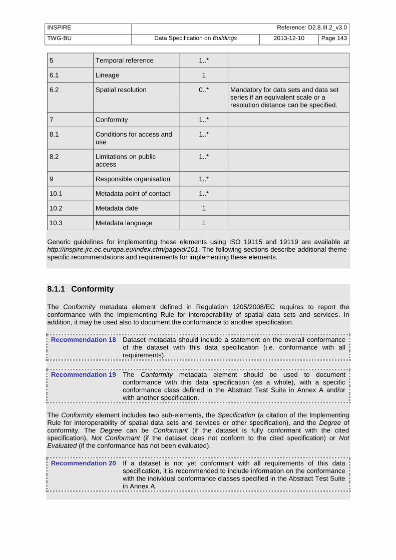
INSPIRE Reference: D2.8.III.2_v3.0
TWG-BU Data Specification on Buildings 2013-12-10 Page 143
5 Temporal reference 1..*
6.1 Lineage 1
6.2 Spatial resolution 0..* Mandatory for data sets and data set series if an equivalent scale or a resolution distance can be specified.
7 Conformity 1..*
8.1 Conditions for access and use
1..*
8.2 Limitations on public access
1..*
9 Responsible organisation 1..*
10.1 Metadata point of contact 1..*
10.2 Metadata date 1
10.3 Metadata language 1
Generic guidelines for implementing these elements using ISO 19115 and 19119 are available at http://inspire.jrc.ec.europa.eu/index.cfm/pageid/101. The following sections describe additional theme-specific recommendations and requirements for implementing these elements.
8.1.1 Conformity
The Conformity metadata element defined in Regulation 1205/2008/EC requires to report the conformance with the Implementing Rule for interoperability of spatial data sets and services. In addition, it may be used also to document the conformance to another specification.
Recommendation 18 Dataset metadata should include a statement on the overall conformance of the dataset with this data specification (i.e. conformance with all requirements).
Recommendation 19 The Conformity metadata element should be used to document conformance with this data specification (as a whole), with a specific conformance class defined in the Abstract Test Suite in Annex A and/or with another specification.
The Conformity element includes two sub-elements, the Specification (a citation of the Implementing Rule for interoperability of spatial data sets and services or other specification), and the Degree of conformity. The Degree can be Conformant (if the dataset is fully conformant with the cited specification), Not Conformant (if the dataset does not conform to the cited specification) or Not Evaluated (if the conformance has not been evaluated).
Recommendation 20 If a dataset is not yet conformant with all requirements of this data specification, it is recommended to include information on the conformance with the individual conformance classes specified in the Abstract Test Suite in Annex A.

INSPIRE Reference: D2.8.III.2_v3.0
TWG-BU Data Specification on Buildings 2013-12-10 Page 144
Recommendation 21 If a dataset is produced or transformed according to an external specification that includes specific quality assurance procedures, the conformity with this specification should be documented using the Conformity metadata element.
Recommendation 22 If minimum data quality recommendations are defined then the statement on the conformity with these requirements should be included using the Conformity metadata element and referring to the relevant data quality
conformance class in the Abstract Test Suite.
NOTE Currently no minimum data quality requirements are included in the IRs. The recommendation above should be included as a requirement in the IRs if minimum data quality requirements are defined at some point in the future.
Recommendation 23 When documenting conformance with this data specification or one of the conformance classes defined in the Abstract Test Suite, the Specification sub-element should be given using the http URI identifier of the conformance class or using a citation including the following elements:
- title: ―INSPIRE Data Specification on Buildings – Draft Guidelines – <name of the conformance class>‖
- date: - dateType: publication - date: 2013-04-10
EXAMPLE 1: The XML snippets below show how to fill the Specification sub-element for documenting conformance with the whole data specification on Addresses v3.0.1. <gmd:DQ_ConformanceResult> <gmd:specification href="http://inspire.ec.europa.eu/conformanceClass/ad/3.0.1/tg" />
<gmd:explanation> (...) </gmd:explanation> <gmd:pass> (...) </gmd:pass> </gmd:DQ_ConformanceResult> or (using a citation): <gmd:DQ_ConformanceResult> <gmd:specification>
<gmd:CI_Citation> <gmd:title> <gco:CharacterString>INSPIRE Data Specification on Buildings – Draft Guidelines</gco:CharacterString> </gmd:title>
<gmd:date> <gmd:date> <gco:Date>2013-04-10</gco:Date>
</gmd:date> <gmd:dateType> <gmd:CI_DateTypeCode codeList="http://standards.iso.org/ittf/PubliclyAvailableStandards/ISO_19139_Schemas/resou rces/codelist/ML_gmxCodelists.xml#CI_DateTypeCode" codeListValue="publication">publication</gmd:CI_DateTypeCode>
</gmd:dateType> </gmd:date> </gmd:CI_Citation> </gmd:specification>
<gmd:explanation> (...) </gmd:explanation> <gmd:pass> (...) </gmd:pass> </gmd:DQ_ConformanceResult>

INSPIRE Reference: D2.8.III.2_v3.0
TWG-BU Data Specification on Buildings 2013-12-10 Page 145
EXAMPLE 2: The XML snippets below show how to fill the Specification sub-element for documenting conformance with the CRS conformance class of the data specification on Addresses v3.0.1. <gmd:DQ_ConformanceResult> <gmd:specification href="http://inspire.ec.europa.eu/conformanceClass/ad/3.0.1/crs" />
<gmd:explanation> (...) </gmd:explanation> <gmd:pass> (...) </gmd:pass> </gmd:DQ_ConformanceResult> or (using a citation): <gmd:DQ_ConformanceResult> <gmd:specification>
<gmd:CI_Citation> <gmd:title> <gco:CharacterString>INSPIRE Data Specification on Buildings – Draft Guidelines – CRS</gco:CharacterString> </gmd:title>
<gmd:date> <gmd:date> <gco:Date>2013-04-10</gco:Date>
</gmd:date> <gmd:dateType> <gmd:CI_DateTypeCode codeList="http://standards.iso.org/ittf/PubliclyAvailableStandards/ISO_19139_Schemas/resou rces/codelist/ML_gmxCodelists.xml#CI_DateTypeCode" codeListValue="publication">publication</gmd:CI_DateTypeCode>
</gmd:dateType> </gmd:date> </gmd:CI_Citation> </gmd:specification>
<gmd:explanation> (...) </gmd:explanation> <gmd:pass> (...) </gmd:pass> </gmd:DQ_ConformanceResult>
8.1.2 Lineage
Recommendation 24 Following the ISO/DIS 19157 Quality principles, if a data provider has a procedure for the quality management of their spatial data sets then the appropriate data quality elements and measures defined in ISO/DIS 19157 should be used to evaluate and report (in the metadata) the results. If not, the Lineage metadata element (defined in Regulation 1205/2008/EC)
should be used to describe the overall quality of a spatial data set.
According to Regulation 1205/2008/EC, lineage ―is a statement on process history and/or overall quality of the spatial data set. Where appropriate it may include a statement whether the data set has been validated or quality assured, whether it is the official version (if multiple versions exist), and whether it has legal validity. The value domain of this metadata element is free text‖. The Metadata Technical Guidelines based on EN ISO 19115 and EN ISO 19119 specifies that the statement sub-element of LI_Lineage (EN ISO 19115) should be used to implement the lineage metadata element.

INSPIRE Reference: D2.8.III.2_v3.0
TWG-BU Data Specification on Buildings 2013-12-10 Page 146
Recommendation 25 To describe the transformation steps and related source data, it is recommended to use the following sub-elements of LI_Lineage:
- For the description of the transformation process of the local to the common INSPIRE data structures, the LI_ProcessStep sub-element should be used.
- For the description of the source data the LI_Source sub-element should be used.
NOTE 1 In order to improve the interoperability, domain templates and instructions for using these free text elements (descriptive statements) may be specified here and/or in an Annex of this data specification.
8.1.3 Lineage from MD Regulation Lineage is one of the metadata elements coming from the Implementing Rule about Metadata. According to ISO 19115, it may be sub-divided into:
- LI-source : information about the source data used in creating the data set received by the user (the INSPIRE data set)
- LI-process: information about events or transformations in the life of the dataset received by the user (the INSPIRE data set).
However, the INSPIRE data set will generally have been provided following a complex process, that may be summarised by the figure below.
Recommendation 6 To fill the metadata elements Source and Process, the source should be considered as the local/national data base used to derive the INSPIRE data set and the process as the transformations carried out to make this local/national data base compliant with INSPIRE.
8.1.3.1. Source
Information about the source
Metadata element name Information about the source

INSPIRE Reference: D2.8.III.2_v3.0
TWG-BU Data Specification on Buildings 2013-12-10 Page 147
Definition
Information about the source data used in creating the data specified by the scope
ISO 19115 number and name
85. source
ISO/TS 19139 path
dataQualityInfo/lineage/LI_Lineage/source
INSPIRE obligation / condition
optional
INSPIRE multiplicity 0..*
Data type (and ISO 19115 no.)
92.LI_Source
Domain
See B.2.4.2.3. This is a complex type (lines 93-98 from ISO 19115). Either the description (free text) or the sourceExtent (EX_Extent) properties shall be provided.
Implementing instructions Information about the source data used in creating the data specified by the scope
Example
Example XML encoding

INSPIRE Reference: D2.8.III.2_v3.0
TWG-BU Data Specification on Buildings 2013-12-10 Page 148
Comments
This metadata element aims to supplement the Lineage metadata element defined in Regulation 1205/2008/EC with a precise description of data sources that have been used as input to generate the INSPIRE building dataset. It is recommended to describe:
the main characteristics of the local or national data base used to derive the INSPIRE data set: name, geographic extent, scale or level of detail, purpose, history, ….
for each significant INSPIRE attribute or group of attributes (geometric or semantics), a short description of the source and process
Example A: 1. This INSPIRE data set has been derived from BD
TOPO; BD TOPO covers whole French territory, is captured at scale 1/ 10 000, exists since 1990 and aims to provide reference data for mapping and spatial analysis.
2. Geometry, height above ground and elevation have been captured by stereo-plotting from aerial images at scale 1/ 20 000. Building nature and building use have been captured also by stereo-plotting plotting from aerial images at scale 1/ 20 000 and then have been checked by field survey.
Example B: This INSPIRE data set has been derived from cadastral data base of the Spanish Directorate General for Cadastre that is the Spanish Public Administration responsible for describing the real-estate properties of the country, being in charge of providing and keeping updated the Real-estate Cadastre as well as of taking care of the correct diffusion of Cadastral data for 95% of the Spanish surface with exception of Basque country and Navarra. Now the cadastral data base has a continuous map with urban and rural cartography, and with all the municipalities aggregated in a unique data base but in origin: Digital urban cartography 1:500 or 1:1000 was generated at the municipal level from the digitalisation of existing cadastral cartography following verification of its quality, or using new cartography generated by a process of analytical restitution of apparent parcellary entities obtained in stereographical flights upon which the cadastral parcellary data is placed, identified and updated. 1. Photogrametrical numerical restitution 2. " Fieldwork and later edition in office to obtain an apparent parcellary on which to incorporate the property parcellary " 3. " semantic Treatment: codification, alteration and assignment of cadastral References and labels" The geometry of buildings is composed by several subparcels of different volume constructed. For every volume the number of floors is represented and it permits to build the 3D data. Also for every building, there is a scaled graphic representation of the units forming an urban real estate. The data is daily updated by field work on this basis. building.

INSPIRE Reference: D2.8.III.2_v3.0
TWG-BU Data Specification on Buildings 2013-12-10 Page 149
8.1.3.2. ProcessStep
Information about events
Metadata element name Information about the source
Definition
Information about an event or transformation in the life of a dataset including the process used to maintain the dataset
ISO 19115 number and name
84. processStep
ISO/TS 19139 path
dataQualityInfo/lineage/LI_Lineage/processStep
INSPIRE obligation / condition
optional
INSPIRE multiplicity 0..*
Data type (and ISO 19115 no.)
86. LI_ProcessStep
Domain
See B.2.4.2.2. This is a complex type (lines 87-91 from ISO 19115). The description (free text) property shall be provided.
Implementing instructions
Example
Example XML encoding

INSPIRE Reference: D2.8.III.2_v3.0
TWG-BU Data Specification on Buildings 2013-12-10 Page 150
Comments
This metadata element aims to supplement the Lineage metadata element defined in Regulation 1205/2008/EC with a precise description of a process or operation that has been applied to make national/local data base compliant with INSPIRE building specifications. It is recommended to describe:
1. the schema transformation to make initial source compliant with INSPIRE ; possibly, provide the internet address of the transformation report, if any
2. the coordinate transformation to make initial source compliant with INSPIRE
3. any transformation/process that has been done to make INSPIRE data consistent with other themes, with other levels of detail or with similar data on neighbour areas (i.e. edge-matching)
Examples:
1. BD TOPO data have been transformed into INSPIRE model, under PosGreSQL using home-made scripts and then provided in GML by GeoServer. Matching rules are documented in the transformation report available at: http://ign.fr
2. BD TOPO data have been transformed from French coordinate reference system (RGF93 – projected coordinates in Lambert-93) into INSPIRE coordinate reference system (ETRS89 – geographic coordinates) by coordinate conversion. Elevation and Z coordinate of geometry have been transformed from IG69 to EVRS by adding a constant value (not exact transformation)
3. Buildings being captured from same source and according to same process as other topographic themes, INSPIRE theme BU is geometrically consistent with other INSPIRE themes (TN, HY, AU, GN, AD) provided from the same national source (BD TOPO). Currently, no edge-matching done with neighbouring countries.
8.1.4 Temporal reference
According to Regulation 1205/2008/EC, at least one of the following temporal reference metadata sub-elements shall be provided: temporal extent, date of publication, date of last revision, date of creation.
Recommendation 26 It is recommended that at least the date of the last revision of a spatial data set should be reported using the Date of last revision metadata sub-
element.
8.2 Metadata elements for interoperability

INSPIRE Reference: D2.8.III.2_v3.0
TWG-BU Data Specification on Buildings 2013-12-10 Page 151
IR Requirement Article 13
Metadata required for Interoperability The metadata describing a spatial data set shall include the following metadata elements required for interoperability: 1. Coordinate Reference System: Description of the coordinate reference system(s) used in the
data set. 2. Temporal Reference System: Description of the temporal reference system(s) used in the data
set. This element is mandatory only if the spatial data set contains temporal information that does
not refer to the default temporal reference system. 3. Encoding: Description of the computer language construct(s) specifying the representation of
data objects in a record, file, message, storage device or transmission channel. 4. Topological Consistency: Correctness of the explicitly encoded topological characteristics of the
data set as described by the scope. This element is mandatory only if the data set includes types from the Generic Network Model
and does not assure centreline topology (connectivity of centrelines) for the network. 5. Character Encoding: The character encoding used in the data set. This element is mandatory only if an encoding is used that is not based on UTF-8.
6. Spatial Representation Type: The method used to spatially represent geographic information.
These Technical Guidelines propose to implement the required metadata elements based on ISO 19115 and ISO/TS 19139. The following TG requirements need to be met in order to be conformant with the proposed encoding.
TG Requirement 3 Metadata instance (XML) documents shall validate without error against the used ISO 19139 XML schema.
NOTE Section 2.1.2 of the Metadata Technical Guidelines discusses the different ISO 19139 XML schemas that are currently available.
TG Requirement 4 Metadata instance (XML) documents shall contain the elements and meet the INSPIRE multiplicity specified in the sections below.
TG Requirement 5 The elements specified below shall be available in the specified ISO/TS 19139 path.
Recommendation 27 The metadata elements for interoperability should be made available together with the metadata elements defined in the Metadata Regulation through an INSPIRE discovery service.
NOTE While this not explicitly required by any of the INSPIRE Implementing Rules, making all metadata of a data set available together and through one service simplifies implementation and usability.

INSPIRE Reference: D2.8.III.2_v3.0
TWG-BU Data Specification on Buildings 2013-12-10 Page 152
8.2.1 Coordinate Reference System
Metadata element name Coordinate Reference System
Definition Description of the coordinate reference system used in the dataset.
ISO 19115 number and name 13. referenceSystemInfo
ISO/TS 19139 path referenceSystemInfo
INSPIRE obligation / condition mandatory
INSPIRE multiplicity 1..*
Data type(and ISO 19115 no.) 186. MD_ReferenceSystem
Domain
To identify the reference system, the referenceSystemIdentifier (RS_Identifier) shall be provided. NOTE More specific instructions, in particular on pre-defined values for filling the referenceSystemIdentifier attribute should be agreed among Member States during the implementation phase to support interoperability.
Implementing instructions
Example referenceSystemIdentifier: code: ETRS_89 codeSpace: INSPIRE RS registry
Example XML encoding
<gmd:referenceSystemInfo> <gmd:MD_ReferenceSystem> <gmd:referenceSystemIdentifier> <gmd:RS_Identifier> <gmd:code> <gco:CharacterString>ETRS89 </gco:CharacterString> </gmd:code> <gmd:codeSpace> <gco:CharacterString>INSPIRE RS registry</gco:CharacterString> </gmd:codeSpace> </gmd:RS_Identifier> </gmd:referenceSystemIdentifier> </gmd:MD_ReferenceSystem> </gmd:referenceSystemInfo>
Comments
8.2.2 Temporal Reference System
Metadata element name Temporal Reference System
Definition Description of the temporal reference systems used in the dataset.
ISO 19115 number and name 13. referenceSystemInfo
ISO/TS 19139 path referenceSystemInfo
INSPIRE obligation / condition Mandatory, if the spatial data set or one of its feature types contains temporal information that does not refer to the Gregorian Calendar or the Coordinated Universal Time.
INSPIRE multiplicity 0..*
Data type(and ISO 19115 no.) 186. MD_ReferenceSystem

INSPIRE Reference: D2.8.III.2_v3.0
TWG-BU Data Specification on Buildings 2013-12-10 Page 153
Domain
No specific type is defined in ISO 19115 for temporal reference systems. Thus, the generic MD_ReferenceSystem element and its reference SystemIdentifier (RS_Identifier) property shall be provided. NOTE More specific instructions, in particular on pre-defined values for filling the referenceSystemIdentifier attribute should be agreed among Member States during the implementation phase to support interoperability.
Implementing instructions
Example referenceSystemIdentifier: code: GregorianCalendar codeSpace: INSPIRE RS registry
Example XML encoding
<gmd:referenceSystemInfo> <gmd:MD_ReferenceSystem> <gmd:referenceSystemIdentifier> <gmd:RS_Identifier> <gmd:code> <gco:CharacterString>GregorianCalendar </gco:CharacterString> </gmd:code> <gmd:codeSpace> <gco:CharacterString>INSPIRE RS registry</gco:CharacterString> </gmd:codeSpace> </gmd:RS_Identifier> </gmd:referenceSystemIdentifier> </gmd:MD_ReferenceSystem> </gmd:referenceSystemInfo>
Comments
8.2.3 Encoding
Metadata element name Encoding
Definition Description of the computer language construct that specifies the representation of data objects in a record, file, message, storage device or transmission channel
ISO 19115 number and name 271. distributionFormat
ISO/TS 19139 path distributionInfo/MD_Distribution/distributionFormat
INSPIRE obligation / condition mandatory
INSPIRE multiplicity 1
Data type (and ISO 19115 no.) 284. MD_Format
Domain See B.2.10.4. The property values (name, version, specification) specified in section 5 shall be used to document the default and alternative encodings.
Implementing instructions
Example
name: <Application schema name> GML application schema version: version 3.0 specification: D2.8.III.2 Data Specification on Buildings – Technical Guidelines

INSPIRE Reference: D2.8.III.2_v3.0
TWG-BU Data Specification on Buildings 2013-12-10 Page 154
Example XML encoding
<gmd:MD_Format> <gmd:name> <gco:CharacterString>SomeApplicationSchema GML application schema</gco:CharacterString> </gmd:name> <gmd:version> <gco:CharacterString>3.0</gco:CharacterString> </gmd:version> <gmd:specification> <gco:CharacterString>D2.8.III.2 Data Specification on Buildings – Technical Guidelines</gco:CharacterString> </gmd:specification> </gmd:MD_Format>
Comments
8.2.4 Character Encoding
Metadata element name Character Encoding
Definition The character encoding used in the data set.
ISO 19115 number and name
ISO/TS 19139 path
INSPIRE obligation / condition Mandatory, if an encoding is used that is not based on UTF-8.
INSPIRE multiplicity 0..*
Data type (and ISO 19115 no.)
Domain
Implementing instructions
Example -
Example XML encoding
<gmd:characterSet> <gmd:MD_CharacterSetCode codeListValue="8859part2" codeList="http://standards.iso.org/ittf/PubliclyAvailableStandards/ISO_19139_Schemas/resources/codelist/ML_gmxCodelists.xml#CharacterSetCode">8859-2</gmd:MD_CharacterSetCode> </gmd:characterSet>
Comments
8.2.5 Spatial representation type
Metadata element name Spatial representation type
Definition The method used to spatially represent geographic information.
ISO 19115 number and name 37. spatialRepresentationType
ISO/TS 19139 path
INSPIRE obligation / condition Mandatory
INSPIRE multiplicity 1..*
Data type (and ISO 19115 no.)
B.5.26 MD_SpatialRepresentationTypeCode
Domain
Implementing instructions
Of the values included in the code list in ISO 19115 (vector, grid, textTable, tin, stereoModel, video), only vector, grid and tin should be used. NOTE Additional code list values may be defined based on feedback from implementation.
Example -
Example XML encoding
Comments

INSPIRE Reference: D2.8.III.2_v3.0
TWG-BU Data Specification on Buildings 2013-12-10 Page 155
8.2.6 Data Quality – Logical Consistency – Topological Consistency See section 8.3.2 for instructions on how to implement metadata elements for reporting data quality.
8.3 Recommended theme-specific metadata elements
Recommendation 28 The metadata describing a spatial data set or a spatial data set series related to the theme Buildings should comprise the theme-specific
metadata elements specified in Table 9.
The table contains the following information:
The first column provides a reference to a more detailed description.
The second column specifies the name of the metadata element.
The third column specifies the multiplicity.
Table 9 – Optional theme-specific metadata elements for the theme Buildings
Section Metadata element Multiplicity
8.3.1 Maintenance Information 0..1
8.3.2 Logical Consistency – Conceptual Consistency 0..*
8.3.2 Logical Consistency – Domain Consistency 0..*
8.3.2 Other DQ element from chapter 7 0..*
8.3.3 Content Information 0..1
Recommendation 29 For implementing the metadata elements included in this section using ISO 19115, ISO/DIS 19157 and ISO/TS 19139, the instructions included in the relevant sub-sections should be followed.
8.3.1 Maintenance Information
Metadata element name Maintenance information
Definition Information about the scope and frequency of updating
ISO 19115 number and name 30. resourceMaintenance
ISO/TS 19139 path identificationInfo/MD_Identification/resourceMaintenance
INSPIRE obligation / condition optional
INSPIRE multiplicity 0..1
Data type(and ISO 19115 no.) 142. MD_MaintenanceInformation

INSPIRE Reference: D2.8.III.2_v3.0
TWG-BU Data Specification on Buildings 2013-12-10 Page 156
Domain
This is a complex type (lines 143-148 from ISO 19115). At least the following elements should be used (the multiplicity according to ISO 19115 is shown in parentheses):
maintenanceAndUpdateFrequency [1]: frequency with which changes and additions are made to the resource after the initial resource is completed / domain value: MD_MaintenanceFrequencyCode:
updateScope [0..*]: scope of data to which maintenance is applied / domain value: MD_ScopeCode
maintenanceNote [0..*]: information regarding specific requirements for maintaining the resource / domain value: free text
Implementing instructions
Example
Example XML encoding
Comments
8.3.2 Metadata elements for reporting data quality
Recommendation 30 For reporting the results of the data quality evaluation, the data quality elements, sub-elements and (for quantitative evaluation) measures defined in chapter 7 should be used.
Recommendation 31 The metadata elements specified in the following sections should be used to report the results of the data quality evaluation. At least the information included in the row ―Implementation instructions‖ should be provided.
The first section applies to reporting quantitative results (using the element DQ_QuantitativeResult), while the second section applies to reporting non-quantitative results (using the element DQ_DescriptiveResult).
Recommendation 32 If a dataset does not pass the tests of the Application schema conformance class (defined in Annex A), the results of each test should be reported using one of the options described in sections 8.3.2.1 and 8.3.2.2.
NOTE 1 If using non-quantitative description, the results of several tests do not have to be reported separately, but may be combined into one descriptive statement. NOTE 2 The sections 8.3.2.1 and 8.3.2.2 may need to be updated once the XML schemas for ISO 19157 have been finalised. The scope for reporting may be different from the scope for evaluating data quality (see section 7). If data quality is reported at the data set or spatial object type level, the results are usually derived or aggregated.
Recommendation 33 The scope element (of type DQ_Scope) of the DQ_DataQuality subtype should be used to encode the reporting scope.
Only the following values should be used for the level element of
DQ_Scope: Series, Dataset, featureType. If the level is featureType the
levelDescription/MDScopeDescription/features element (of type Set< GF_FeatureType>) shall be used to list the feature type names.
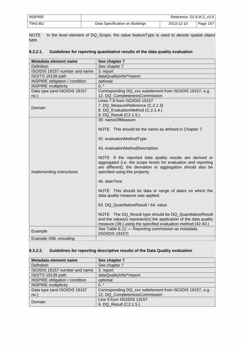
INSPIRE Reference: D2.8.III.2_v3.0
TWG-BU Data Specification on Buildings 2013-12-10 Page 157
NOTE In the level element of DQ_Scope, the value featureType is used to denote spatial object type.
8.3.2.1. Guidelines for reporting quantitative results of the data quality evaluation
Metadata element name See chapter 7
Definition See chapter 7
ISO/DIS 19157 number and name 3. report
ISO/TS 19139 path dataQualityInfo/*/report
INSPIRE obligation / condition optional
INSPIRE multiplicity 0..*
Data type (and ISO/DIS 19157 no.)
Corresponding DQ_xxx subelement from ISO/DIS 19157, e.g. 12. DQ_CompletenessCommission
Domain
Lines 7-9 from ISO/DIS 19157 7. DQ_MeasureReference (C.2.1.3) 8. DQ_EvaluationMethod (C.2.1.4.) 9. DQ_Result (C2.1.5.)
Implementing instructions
39. nameOfMeasure NOTE This should be the name as defined in Chapter 7. 42. evaluationMethodType 43. evaluationMethodDescription NOTE If the reported data quality results are derived or aggregated (i.e. the scope levels for evaluation and reporting are different), the derivation or aggregation should also be specified using this property. 46. dateTime NOTE This should be data or range of dates on which the data quality measure was applied. 63. DQ_QuantitativeResult / 64. value NOTE The DQ_Result type should be DQ_QuantitativeResult and the value(s) represent(s) the application of the data quality measure (39.) using the specified evaluation method (42-43.)
Example See Table E.12 — Reporting commission as metadata (ISO/DIS 19157)
Example XML encoding
8.3.2.2. Guidelines for reporting descriptive results of the Data Quality evaluation
Metadata element name See chapter 7
Definition See chapter 7
ISO/DIS 19157 number and name 3. report
ISO/TS 19139 path dataQualityInfo/*/report
INSPIRE obligation / condition optional
INSPIRE multiplicity 0..*
Data type (and ISO/DIS 19157 no.)
Corresponding DQ_xxx subelement from ISO/DIS 19157, e.g. 12. DQ_CompletenessCommission
Domain Line 9 from ISO/DIS 19157 9. DQ_Result (C2.1.5.)

INSPIRE Reference: D2.8.III.2_v3.0
TWG-BU Data Specification on Buildings 2013-12-10 Page 158
Implementing instructions
67. DQ_DescripitveResult / 68. statement NOTE The DQ_Result type should be DQ_DescriptiveResult and in the statement (68.) the evaluation of the selected DQ sub-element should be expressed in a narrative way.
Example See Table E.15 — Reporting descriptive result as metadata (ISO/DIS 19157)
Example XML encoding
8.3.3 Content information
Metadata element name <MD_ContentInformation >
Definition description of the content of a dataset
ISO 19115 number and name MD_ContentInformation
ISO/TS 19139 path
INSPIRE obligation / condition optional
INSPIRE multiplicity 0..1
Data type (and ISO 19115 no.)
MD_FeatureCatalogue Description
Domain MD_FeatureCatalogue
Implementing instructions
The purpose of this metadata element is to inform the user about the feature types and properties that are populated in the data set. This has to be done by a reference to a feature catalogue including only the populated feature types and properties. It may be done by referencing the tables supplied in annex E for additional information once they have been filled by the data producer, just by ticking the populated features and properties.
Example
Example XML encoding
Comments)
8.3.4 Template for additional information The data specification for theme Buildings is quite flexible and adaptable by data producers. Therefore, there is a need that users are informed about how the INSPIRE specification has been interpreted and adapted. Typically, users would need to get explanations about the specificities remaining in a data set, even once it has been made INSPIRE conformant. The main information elements to be provided by data producers in complement of the INSPIRE specifications have been identified by TWG BU in annex E: template for additional information. There are two ways to use this template: - data producer supplies to users both the INSPIRE specification and the template for additional information to complement it - data producer makes its own specification based on INSPIRE one by integrating the information elements supplied in the template for additional data. These documents (INSPIRE specification + template for additional information or customized INSPIRE specification) are dedicated to human being users; they are not supposed to provide searchable metadata elements. These documents must be made available to users in a way or another. For instance, they may at least be published on the data provider Web site. If possible, they should be made available through the download services.

INSPIRE Reference: D2.8.III.2_v3.0
TWG-BU Data Specification on Buildings 2013-12-10 Page 159
9 Delivery
9.1 Updates
IR Requirement Article 8 Updates
1. Member States shall make available updates of data on a regular basis. 2. All updates shall be made available at the latest 6 months after the change was applied in the
source data set, unless a different period is specified for a specific spatial data theme in Annex
II.
NOTE In this data specification, no exception is specified, so all updates shall be made available at the latest 6 months after the change was applied in the source data set.
9.2 Delivery medium According to Article 11(1) of the INSPIRE Directive, Member States shall establish and operate a network of services for INSPIRE spatial data sets and services. The relevant network service types for making spatial data available are: - view services making it possible, as a minimum, to display, navigate, zoom in/out, pan, or overlay
viewable spatial data sets and to display legend information and any relevant content of metadata; - download services, enabling copies of spatial data sets, or parts of such sets, to be downloaded
and, where practicable, accessed directly; - transformation services, enabling spatial data sets to be transformed with a view to achieving
interoperability. NOTE For the relevant requirements and recommendations for network services, see the relevant Implementing Rules and Technical Guidelines
15.
EXAMPLE 1 Through the Get Spatial Objects function, a download service can either download a pre-defined data set or pre-defined part of a data set (non-direct access download service), or give direct access to the spatial objects contained in the data set, and download selections of spatial objects based upon a query (direct access download service). To execute such a request, some of the following information might be required:
the list of spatial object types and/or predefined data sets that are offered by the download service (to be provided through the Get Download Service Metadata operation),
and the query capabilities section advertising the types of predicates that may be used to form a query expression (to be provided through the Get Download Service Metadata operation, where applicable),
a description of spatial object types offered by a download service instance (to be provided through the Describe Spatial Object Types operation).
EXAMPLE 2 Through the Transform function, a transformation service carries out data content transformations from native data forms to the INSPIRE-compliant form and vice versa. If this operation
15
The Implementing Rules and Technical Guidelines on INSPIRE Network Services are available at http://inspire.jrc.ec.europa.eu/index.cfm/pageid/5

INSPIRE Reference: D2.8.III.2_v3.0
TWG-BU Data Specification on Buildings 2013-12-10 Page 160
is directly called by an application to transform source data (e.g. obtained through a download service) that is not yet conformant with this data specification, the following parameters are required: Input data (mandatory). The data set to be transformed.
Source model (mandatory, if cannot be determined from the input data). The model in which the input data is provided.
Target model (mandatory). The model in which the results are expected.
Model mapping (mandatory, unless a default exists). Detailed description of how the transformation is to be carried out.
9.3 Encodings The IRs contain the following two requirements for the encoding to be used to make data available.
IR Requirement Article 7
Encoding
1. Every encoding rule used to encode spatial data shall conform to EN ISO 19118. In particular, it shall specify schema conversion rules for all spatial object types and all attributes and association roles and the output data structure used.
2. Every encoding rule used to encode spatial data shall be made available.
NOTE ISO 19118:2011 specifies the requirements for defining encoding rules used for interchange of geographic data within the set of International Standards known as the ―ISO 19100 series‖. An encoding rule allows geographic information defined by application schemas and standardized schemas to be coded into a system-independent data structure suitable for transport and storage. The encoding rule specifies the types of data being coded and the syntax, structure and coding schemes used in the resulting data structure. Specifically, ISO 19118:2011 includes - requirements for creating encoding rules based on UML schemas, - requirements for creating encoding services, and - requirements for XML-based encoding rules for neutral interchange of data. While the IRs do not oblige the usage of a specific encoding, these Technical Guidelines propose to make data related to the spatial data theme Buildings available at least in the default encoding(s) specified in section 9.3.1. In this section, a number of TG requirements are listed that need to be met in order to be conformant with the default encoding(s). The proposed default encoding(s) meet the requirements in Article 7 of the IRs, i.e. they are conformant with ISO 19118 and (since they are included in this specification) publicly available.
9.3.1 Default Encoding(s)
9.3.1.1. Specific requirements for GML encoding This data specification proposes the use of GML as the default encoding, as recommended in sections 7.2 and 7.3 of [DS-D2.7]. GML is an XML encoding in compliance with ISO 19118, as required in Article
7(1). For details, see [ISO 19136], and in particular Annex E (UML-to-GML application schema encoding rules). The following TG requirements need to be met in order to be conformant with GML encodings.
TG Requirement 6 Data instance (XML) documents shall validate without error against the provided XML schema.

INSPIRE Reference: D2.8.III.2_v3.0
TWG-BU Data Specification on Buildings 2013-12-10 Page 161
NOTE 1 Not all constraints defined in the application schemas can be mapped to XML. Therefore, the following requirement is necessary. NOTE 2 The obligation to use only the allowed code list values specified for attributes and most of the constraints defined in the application schemas cannot be mapped to the XML sch. They can therefore not be enforced through schema validation. It may be possible to express some of these constraints using other schema or rule languages (e.g. Schematron), in order to enable automatic validation.
9.3.1.2. Default encoding(s) for application schema BuildingsBase Name: BuildingsBase GML Application Schema Version: version 3.0 Specification: D2.8.III.2 Data Specification on Buildings – Technical Guidelines Character set: UTF-8 The xml schema document is available on the INSPIRE website http://inspire.ec.europa.eu/schemas/bu-base/3.0/BuildingsBase.xsd.
9.3.1.3. Default encoding(s) for application schema Buildings2D Name: Buildings2D GML Application Schema Version: version 3.0 Specification: D2.8.III.2 Data Specification on Buildings – Technical Guidelines Character set: UTF-8 The xml schema document is available on the INSPIRE website http://inspire.ec.europa.eu/schemas/bu-core2d/3.0/BuildingsCore2D.xsd.
9.3.1.4. Default encoding(s) for application schema Buildings3D Name: Buildings3D GML Application Schema Version: version 3.0 Specification: D2.8.III.2 Data Specification on Buildings – Technical Guidelines Character set: UTF-8 The xml schema document is available on the INSPIRE website http://inspire.ec.europa.eu/schemas/bu-core3d/3.0/BuildingsCore3D.xsd.
9.3.1.5. Default encoding(s) for application schema BuildingsExtendedBase Name: BuildingsExtendedBase GML Application Schema Version: version 3.0 Specification: D2.8.III.2 Data Specification on Buildings – Technical Guidelines Character set: UTF-8 The xml schema document is available on the INSPIRE website http://inspire.ec.europa.eu/draft-schemas/bu-ext/3.0/BuildingsExtendedBase.xsd.
9.3.1.6. Default encoding(s) for application schema BuildingsExtended2D Name: BuildingsExtended2D GML Application Schema Version: version 3.0 Specification: D2.8.III.2 Data Specification on Buildings – Technical Guidelines Character set: UTF-8 The xml schema document is available on the INSPIRE website

INSPIRE Reference: D2.8.III.2_v3.0
TWG-BU Data Specification on Buildings 2013-12-10 Page 162
http://inspire.ec.europa.eu/schemas/draft-schemas/bu-ext2d/3.0/BuildingsExtended2D.xsd.
9.3.1.7. Default encoding(s) for application schema BuildingsExtended3D Name: BuildingsExtended3D GML Application Schema Version: version 3.0 Specification: D2.8.III.2 Data Specification on Buildings – Technical Guidelines Character set: UTF-8 The xml schema document is available on the INSPIRE website http://inspire.ec.europa.eu/schemas/draft-schemas/bu-ext3d/3.0/BuildingsExtended3D.xsd.
9.3.2 Recommended Encoding(s)
Recommendation 34 It is recommended that also the encodings specified in this section be provided for the relevant application schemas.
9.3.2.1. Alternative encoding for application schema BuildingsExtended3D
9.3.2.1.1. Context- rationale The two 3D profiles of the INSPIRE building model (Core 3D profile and Extended 3D profile) share many properties with CityGML, particularly the representation of the 3D geometry. Currently, there are many tools which support CityGML (see Gröger & Plümer 2012 or www.citygmlwiki.org for details): data capturing tools providing output data in CityGML format, visualization tools which offer CityGML as input format, tools for checking consistency, Web Feature Services which read and provide CityGML, and data bases which store data based on CityGML and provide corresponding interfaces. Due to an increasing international usage and availability of CityGML in many cities and municipalities in Europe, the Middle East and Asia as well as in various organizations and universities all over Europe this list of tools is expected to grow significantly in the future. However, these CityGML tools cannot be used directly for INSPIRE building data, since the standard encodings of the four INSPIRE profiles differ from the CityGML encoding, even if the conceptual INSPIRE application schemas widely use the CityGML concepts. In order to utilize these tools also for INSPIRE building data, an alternative encoding based on CityGML is provided here. CityGML provides a mechanism for adding application specific extensions to the CityGML model. This mechanism is called Application Domain Extension (ADE). An ADE is a sub-schema of CityGML through which new attributes, geometries, and relations can be added to existing CityGML classes such as the number of dwellings to the class AbstractBuilding. Moreover, also new classes can be added to the CityGML model such as OtherConstruction. These new classes typically are sub-classes of appropriate CityGML classes (e.g., of Building or of the topmost class CityObject). An ADE is an application schema in its own namespace, which imports the XML schema definitions of relevant CityGML modules. Formally, an ADE is specified as an XML schema, enabling the validation of instance documents against this schema. Examples for existing CityGML ADEs are the NoiseADE for noise simulation and mapping, the facility management ADE, the UtilityNetworkADE, and the HydroADE for hydrographical applications. Furthermore, the new national geospatial standard in the Netherlands which integrates 2D and 3D data is implemented as CityGML ADE.
9.3.2.1.2. Narrative description
A CityGML ADE currently is provided for the Core 3D profile (application schema Buildings3D) of the INSPIRE building model. An ADE for the Extended 3D profile (application schema BuildingsExtended3D) is in preparation. In these ADEs, those properties which are shared by INSPIRE and CityGML are inherited from CityGML, while properties which are different or additional in INSPIRE are defined in the CityGML ADE for INSPIRE. Constraints are employed to describe these

INSPIRE Reference: D2.8.III.2_v3.0
TWG-BU Data Specification on Buildings 2013-12-10 Page 163
definitions and settings. For more details on the CityGML ADE for the INSPIRE Core 3D profile, see Gröger, Kutzner & Kolbe (2013).
The UML diagram of the CityGML ADE for the Core 3D profile is depicted in Figure 60 and Figure 61, and the conceptual mapping between the UML classes Building and BuildingPart of the INSPIRE Core 3D profile and their encoding (GML object elements and types) in Table 10. In the left part of Figure 60, the classes AbstractBuilding, Building and BuildingPart from the CityGML Building module are shown. The attributes and relations which are specific to INSPIRE are provided by the ADE class AbstractBuilding in the INSPIRE::ADE::Core3D package. These attributes and relations are added to the CityGML class AbstractBuilding (and hence, to its sub-classes Building and BuildingPart) in the CityGML::Building package by the so-called hooking mechanism. This mechanism is indicated by the generalization relation marked with the stereotype «ADE»: the triangle points to the class receiving the attributes and relations from the ADE class AbstractBuilding at the other side of the generalization relation which is labeled with the stereotype «ADEElement». Hence, all attributes and relations of the ADE class AbstractBuilding (in ADE namespace) are added to the CityGML class AbstractBuilding (CityGML namespace). The approach how to represent the hooking mechanism in UML is described in van den Brink, Stoter & Zlatanova (2012). Those attributes and relations which are common to both the CityGML building module and the INSPIRE Building module (with regard to semantics and data types) are represented by CityGML. An example is the number of storeys above ground (storeysAboveGround). Those attributes and relations which are specific to INSPIRE and for which no CityGML counterpart is available, or which differ from CityGML with regard to semantics or data type, are represented by the CityGML ADE for Core 3D (class AbstractBuilding). The constraint ‗Mapping of INSPIRE Buildings to CityGML or to the INSPIRE Core 3D ADE‘ included in the UML diagram as well as Table 11 define this mapping. The INSPIRE properties and data types which represent geometry (properties geometry3DLoD1, geometry3DLoD2, …, data types BuildingGeometry3DLoD1, …) have been split: The pure 3D geometry is represented by CityGML properties (lod1Solid, lod2Solid, …), whereas metadata such as accuracy is provided by
the INSPIRE data types mgeometry3DMetadataLoD1, geometry3DMetadataLoD1, …), c.f. Figure 61. In CityGML, a BuildingPart may again have BuildingParts, whereas in INSPIRE parts of parts are not allowed. Furthermore, in CityGML there is no mandatory geometry in the class AbstractBuilding. This is in contrast to INSPIRE, where BuildingParts and Buildings without BuildingParts must have at least one geometry. Therefore, two constrains have been added to enforce the INSPIRE behavior. Note that in the UML diagram, the classes Building and BuildingPart are not necessary for deriving the ADE; they have been included only to make the diagram more understandable. As an example for the CityGML ADE encoding for the Core 3D profile, an instance document representing a simple building is given in Figure 63. The ADE provides a practicable alternative to the native INSPIRE encoding, enabling INSPIRE building data not only to be identified and processed by currently available CityGML software as CityGML Building objects, but also to be combined with other ADEs extending the CityGML Building feature type. Furthermore, the conceptual mapping between the INSPIRE Core 3D profile and the CityGML ADE for Core 3D as described in Table 10 and Table 11 can serve in deriving INSPIRE building data directly from CityGML data and vice versa, creating views in this way. This means, when CityGML data is imported into an INSPIRE data base, the conceptual mapping describes which data have to be read and processed by the importing tool and which data can be skipped. The same holds true when INSPIRE building data is exported to CityGML data. The INSPIRE Core 3D ADE has been developed by the TWG on Buildings in cooperation with the Chair of Geoinformatics at Technische Universität München and the Chair of Geoinformation, Institute for Geodesy and Geoinformation at University of Bonn, Germany. The CityGML ADE for the INSPIRE Extended 3D profile is under preparation and will be supplied and tested by the wider stakeholder community as part of the INSPIRE Maintenance and Implementation Framework.

INSPIRE Reference: D2.8.III.2_v3.0
TWG-BU Data Specification on Buildings 2013-12-10 Page 164
Figure 60: UML diagram (main types) of the CityGML ADE for the Core 3D profile as an alternative encoding.

INSPIRE Reference: D2.8.III.2_v3.0
TWG-BU Data Specification on Buildings 2013-12-10 Page 165
Table 10: Mappings between conceptual UML classes and the associated GML object elements, ML Schema types and GML property types
class Core3D_DataTypes
«dataType»
BuildingGeometry3DMetadataLoD
«voidable»
+ horizontalGeometryEstimatedAccuracy: Length [0..1]
+ verticalGeometryEstimatedAccuracy: Length [0..1]
+ verticalGeometryReference3DBottom: ElevationReferenceValue [0..1]
«dataType»
BuildingGeometry3DMetadataLoD1
«voidable»
+ horizontalGeometryReference: HorizontalGeometryReferenceValue [0..1]
+ verticalGeometryReference3DTop: ElevationReferenceValue [0..1]
constraints
{no point referencing in 3D}
«dataType»
BuildingGeometry3DMetadataLoD2
«voidable»
+ horizontalGeometryReference: HorizontalGeometryReferenceValue [0..1]
constraints
{no point referencing in 3D}
mapping of INSPIRE Buildings to CityGML or to the Core3D ADE
/* The following INSPIRE data types are mapped to Core3D ADE data types
(which provide only subset of the properties, see below) and vice versa:
- BuildingGeometry3DLoD to BuildingGeometry3DMetadataLoD
- BuildingGeometry3DLoD1 to BuildingGeometry3DMetadataLoD1
- BuildingGeometry3DLoD2 to BuildingGeometry3DMetadataLoD2
The following properties of the above mentioned INSPIRE data types are
mapped to equivalent and equally named properties of the above mentioned
Core3D ADE data types and vice versa:
- verticalGeometryReference3DBottom
- horizontalGeometryEstimatedAccuracy
- verticalGeometryEstimatedAccuracy
The following properties of the INSPIRE data type BuildingGeometry3DLoD
are mapped to equivalent CityGML properties and vice versa:
- terrainIntersection to lod1/2/3/4TerrainIntersection
- geometryMultiSurface to lod1/2/3/4MultiSurface
- geometrySolid to lod1/2/3/4Solid */
Figure 61: UML diagram (data types) of the CityGML ADE for INSPIRE Core 3D profile as an alternative encoding.
Table 11: Conceptual mapping between the UML classes, attributes and relations of the INSPIRE Core3D profile and the associated UML classes, attributes and relations of the INSPIRE Core3D CityGML ADE
UML class in the INSPIRE Core 3D profile
UML attribute/ relation (in INSPIRE application schema)
UML class in CityGML / CityGML ADE for INSPIRE Core 3D profile
UML attribute/relation in CityGML / CityGML ADE for INSPIRE Core 3D profile
BuildingsBase:: AbstractConstruction
inspireId INSPIRE::ADE::Core3D:: AbstractBuilding
inspireId
BuildingsBase:: AbstractConstruction
beginLifespanVersion
INSPIRE::ADE::Core3D:: AbstractBuilding
beginLifespanVersion
UML class GML element GML type GML property
INSPIRE:: Core3D::Building
CityGML/building: Building
CityGML/building: BuildingType
n. a.
INSPIRE:: Core3D::BuildingPart
CityGML/building: BuildingPart
CityGML/building: BuildingPartType
n. a.

INSPIRE Reference: D2.8.III.2_v3.0
TWG-BU Data Specification on Buildings 2013-12-10 Page 166
BuildingsBase:: AbstractConstruction
endLifespan Version
INSPIRE::ADE::Core3D:: AbstractBuilding
endLifespanVersion
BuildingsBase:: AbstractConstruction
conditionOf Construction
INSPIRE::ADE::Core3D:: AbstractBuilding
conditionOfConstruction
BuildingsBase:: AbstractConstruction
dateOf Construction
INSPIRE::ADE::Core3D:: AbstractBuilding
dateOfConstruction
BuildingsBase:: AbstractConstruction
dateOf Demolition
INSPIRE::ADE::Core3D:: AbstractBuilding
dateOfDemolition
BuildingsBase:: AbstractConstruction
dateOf Renovation
INSPIRE::ADE::Core3D:: AbstractBuilding
dateOfRenovation
BuildingsBase:: AbstractConstruction
elevation INSPIRE::ADE::Core3D:: AbstractBuilding
Elevation
BuildingsBase:: AbstractConstruction
external Reference
CityGML::Core:: AbstractCityObject
externalReference
BuildingsBase:: AbstractConstruction
heightAbove Ground
INSPIRE::ADE::Core3D:: AbstractBuilding
heightAboveGround
BuildingsBase:: AbstractConstruction
Name INSPIRE::ADE::Core3D:: AbstractBuilding
Name
BuildingsBase:: AbstractBuildung
buildingNature INSPIRE::ADE::Core3D:: AbstractBuilding
buildingNature
BuildingsBase:: AbstractBuildung
currentUse INSPIRE::ADE::Core3D:: AbstractBuilding
currentUse
BuildingsBase:: AbstractBuildung
numberOf Dwellings
INSPIRE::ADE::Core3D:: AbstractBuilding
numberOfDwellings
BuildingsBase:: AbstractBuildung
numberOf BuildingUnits
INSPIRE::ADE::Core3D:: AbstractBuilding
numberOfBuildingUnits
BuildingsBase:: AbstractBuildung
numberOf FloorsAbove Ground
CityGML::Building:: AbstractBuilding
storeysAboveGround
BuildingsBase:: Building
Parts CityGML::Building:: AbstractBuilding
consistsOfBuildingPart
Buildingds3D:: Building
geometry3D LoD1
CityGML::Building:: AbstractBuilding
lod1Solid
INSPIRE::ADE::Core3D:: AbstractBuilding
geometry3DMetadata LoD1
Buildingds3D:: Building
geometry3D LoD2
CityGML::Building:: AbstractBuilding
lod2Solid
INSPIRE::ADE::Core3D:: AbstractBuilding
geometry3DMetadata LoD2
Buildingds3D:: Building
geometry3D LoD3
CityGML::Bbuilding:: AbstractBuilding
lod3Solid
INSPIRE::ADE::Core3D:: AbstractBuilding
geometry3DMetadata LoD3
Buildingds3D:: Building
geometry3D LoD4
CityGML::Building:: AbstractBuildingType
lod4Solid
INSPIRE::ADE::Core3D:: AbstractBuilding
geometry3DMetadata LoD4
Buildingds3D:: Building
geometry2D INSPIRE::ADE::Core3D:: AbstractBuilding
geometry2D
Buildingds3D:: BuildingPart
geometry3D LoD1
CityGML::Building:: AbstractBuilding
lod1Solid
INSPIRE::ADE::Core3D:: AbstractBuilding
geometry3DMetadata LoD1
Buildingds3D:: BuildingPart
geometry3D LoD2
CityGML/Building:: AbstractBuilding
lod2Solid
INSPIRE::ADE::Core3D:: AbstractBuilding
geometry3DMetadata LoD2
Buildingds3D:: geometry3D CityGML::Building:: lod3Solid

INSPIRE Reference: D2.8.III.2_v3.0
TWG-BU Data Specification on Buildings 2013-12-10 Page 167
BuildingPart LoD3 AbstractBuilding
INSPIRE::ADE::Core3D:: AbstractBuilding
geometry3DMetadata LoD3
Buildingds3D:: BuildingPart
geometry3D LoD4
CityGML::Building:: AbstractBuilding
lod4Solid
INSPIRE::ADE::Core3D:: AbstractBuilding
geometry3DMetadata LoD4
Buildingds3D:: BuildingPart
geometry2D INSPIRE::ADE::Core3D:: AbstractBuilding
geometry2D
Buildingds3D:: BuildingGeometry3D LoD
geometryMultiSurface
CityGML::building:: AbstractBuilding
lod1MultiSurface lod2MultiSurface lod3MultiSurface lod4MultiSurface
Buildingds3D:: BuildingGeometry3D LoD
geometrySolid CityGML::Building:: AbstractBuilding
lod1Solid lod2Solid lod3Solid lod4Solid
Buildingds3D:: BuildingGeometry3D LoD
terrain Intersection:
CityGML::Building:: AbstractBuilding
lod1TerrainIntersection lod2TerrainIntersection lod3TerrainIntersection lod4TerrainIntersection
Buildingds3D:: BuildingGeometry3D LoD
Vertical Geometry Reference3D Bottom
INSPIRE::ADE::Core3D:: BuildingGeometry3D MetadataLoD
verticalGeometry Reference3DBottom
Buildingds3D:: BuildingGeometry3D LoD
horizontal Geometry Estimated Accuracy
INSPIRE::ADE::Core3D:: BuildingGeometry3D MetadataLoD
horizontalGeometry EstimatedAccuracy
Buildingds3D:: BuildingGeometry3D LoD
vertical Geometry Estimated Accuracy
INSPIRE::ADE::Core3D:: BuildingGeometry3D MetadataLoD
verticalGeometry EstimatedAccuracy
Buildingds3D:: BuildingGeometry3D LoD1
Horizontal Geometry Reference
INSPIRE::ADE::Core3D:: BuildingGeometry3D MetadataLoD1
horizontalGeometry Reference
Buildingds3D:: BuildingGeometry3D LoD1
Vertical Geometry Reference3D Top
INSPIRE::ADE::Core3D:: BuildingGeometry3D MetadataLoD1
verticalGeometry Reference3DTop
Buildingds3D:: BuildingGeometry3D LoD2
horizontal Geometry Reference
INSPIRE::ADE::Core3D:: BuildingGeometry3D MetadataLoD2
horizontalGeometry Reference

INSPIRE Reference: D2.8.III.2_v3.0
TWG-BU Data Specification on Buildings 2013-12-10 Page 168
Figure 62:: Example instance document for the CityGML ADE for the INSPIRE Core 3D profile
<?xml version="1.0" encoding="UTF-8"?> <core:CityModel xsi:schemaLocation="http://www.citygml.org/ade/inspire/core3dcore3d.xsd http://www.opengis.net/citygml/2.0 http://schemas.opengis.net/citygml/2.0/cityGMLBase.xsd" xmlns:xlink="http://www.w3.org/1999/xlink" xmlns:bldg="http://www.opengis.net/citygml/building/2.0" xmlns:gml="http://www.opengis.net/gml" xmlns:core="http://www.opengis.net/citygml/2.0" xmlns:bu-3d="http://www.citygml.org/ade/inspire/core3d" xmlns:xsi="http://www.w3.org/2001/XMLSchema-instance"> <gml:boundedBy> <gml:Envelope srsName="http://www.opengis.net/def/crs/EPSG/0/7409"> <gml:lowerCorner>370000.0 5805000.0</gml:lowerCorner> <gml:upperCorner>370249.0 5806000.0</gml:upperCorner> </gml:Envelope> </gml:boundedBy> <core:cityObjectMember> <bldg:Building> <bldg:lod1Solid> <gml:Solid> <gml:exterior>
<gml:CompositeSurface> <gml:surfaceMember> <gml:Polygon gml:id="UUID_a988d2a9-d749-4380-abd6-bedae2061d05"> <gml:exterior> <gml:LinearRing gml:id="UUID_8fb76b13-51cf-44ad-a13c-3984495211ee"> <gml:posList srsDimension="3"> 370089.758 5805596.288 30.911 370091.018 5805600.028 30.911 370093.347 5805599.268 30.911 </gml:posList> </gml:LinearRing> </gml:exterior> </gml:Polygon> </gml:surfaceMember> </gml:CompositeSurface> </gml:exterior> </gml:Solid> </bldg:lod1Solid> <bu-3d:inspireId> <base:Identifier xmlns:base="urn:x-inspire:specification:gmlas:BaseTypes:3.2"> <base:localId> To be filled </base:localId> <base:namespace/> </base:Identifier> </bu-3d:inspireId> <bu-3d:conditionOfConstruction xlink:href="http://inspire.ec.europa.eu/codelist/CondidtionOfConstructionValue/functional"/> <bu-3d:geometry3DMetadataLoD1> <bu-3d:BuildingGeometry3DMetadataLoD1> <bu-3d:verticalGeometryEstimatedAccuracy uom="m">0.05 </bu-3d:verticalGeometryEstimatedAccuracy> <bu-3d:horizontalGeometryReference xlink:href="http://inspire.ec.europa.eu/codelist/HorizontalGeometryReferenceValue/aboveGroundEnvelope"/> </bu-3d:BuildingGeometry3DMetadataLoD1> </bu-3d:geometry3DMetadataLoD1> </bldg:Building> </core:cityObjectMember> </core:CityModel>

INSPIRE Reference: D2.8.III.2_v3.0
TWG-BU Data Specification on Buildings 2013-12-10 Page 169
9.4 Data Capture This chapter does not aim to define data capture rules as INSPIRE is based on existing data. The data capture rules of source data are up to each data producer. Data producers should clearly describe any deviations from these guidelines in the metadata. This chapter aims to give some guidelines about how to match existing data to INSPIRE specifications. It is not exhaustive but focus on the aspects that are expected to raise some issues.
9.5 Scope of theme Buildings
9.5.1 Purpose Existing data should be made compliant to INSPIRE, taking into account cost-benefit considerations. The scope of theme Buildings and definition of its core feature type Building are rather generic and may open the door to various interpretations. The costs of transformation will depend on how data related to theme Buildings is organised within a Member State. For instance, some data producers have all constructions in a single feature type whereas other data producers have different feature types for buildings, for annex constructions, for urban furniture …. ; building related data may be scattered between various producers or may be under the responsibility of only one organisation. Making whole scope of theme Buildings compliant to INSPIRE will likely be easier when all data regarding buildings and constructions is within the same feature type or at least in the same data set. This paragraph aims to clarify the interpretation of scope, to provide recommendations about which kinds of buildings and constructions are expected by INSPIRE and so, to assess the benefits of making data compliant to INSPIRE. The general rules or priority are given by the modular scope defined in clause 2.2.
Figure 63: The modular approach for scope of theme Buildings
9.5.2 Code lists The possible values provided in the code lists on current use and on nature of buildings and constructions, provide the general guidelines about what is expected by / should be in INSPIRE. More accurately:

INSPIRE Reference: D2.8.III.2_v3.0
TWG-BU Data Specification on Buildings 2013-12-10 Page 170
The buildings hosting human activities, i.e. buildings whose current use is residential, agriculture, industrial, commerceAndservices are necessary for / strongly expected by many INSPIRE use cases.
The buildings whose current use is ancillary are useful for / expected by some INSPIRE use cases.
The buildings that may be obstacles or valuable landmarks for air traffic, i.e. those whose building nature is arch, dam, tower, lighthouse, silo, windmill, wind turbine, transformer, stadium, storageTank are necessary for / strongly expected by some INSPIRE use cases, air traffic being an international use case.
The buildings whose building nature takes other values (e.g. shed, greenhouse, bunker, canopy, chapel, caveBuilding…) are useful for / expected by some INSPIRE use cases (landscape description, mapping).
The other constructions are also necessary for / strongly expected by some INSPIRE use cases: - elevated constructions (crane, antenna, monument, pylons, …) as obstacles for air traffic - environmental barriers (protectiveStructure, acousticFence, retainingWall) or open air
pools for mitigation of risk and of pollution - bridges and tunnels for planning of rescue itineraries in case of disaster.
NOTE: according to the modular scope, other constructions are under the second priority, due to the expected feasibility issues, but there are quite strong user requirements about these constructions.
Recommendation 7 OtherConstructions should be made available for INSPIRE, as much as possible.
9.5.3 Definition of theme buildings Considered as under scope of the theme Buildings are constructions above and/or underground which are intended or used for the shelter of humans, animals, things, the production of economic goods or the delivery of services and that refer to any structure permanently constructed or erected on its site. NOTE 1: According to the definition, the construction should be permanently constructed or erected on its site. However, the notion of ―permanence‖ may be interpreted in a flexible way. For instance, some types of dwellings are theoretically designed to be mobile (e.g. mobile homes, caravans) or to be used for short time (huts, cabins, shacks, shanties) but are in practice used in permanent way and may require the set up of public services. Moreover, there are strong user requirements for data about precarious habitat (vulnerability to natural risks, improvement of habitat ….).
Recommendation 8 A construction that is considered as permanent enough to be captured in existing data should be published for INSPIRE theme Buildings, especially if
the construction hosts human activities.
NOTE 2: All buildings, whatever their size is, are in the scope of theme Buildings. As explained in clause 1.2.2, the scope is modular with first priority to the big or normal buildings. However, there are exceptions where small buildings are of great interest, such as a hut in mountainous area that may be a valuable landmark or shelter for hikers. Once again, this is generally already taken into account by the capture rules of data producers. NOTE 3: The construction must be above or underground, i.e. it must have a significant height. This excludes ―flat‖ constructions such as roads, railways that should be reported in INSPIRE theme Transport. On the opposite, constructions that are totally or partly underground (bunker, underground stations, underground car parks, swimming pools…) are under scope of theme Building and should be published for INSPIRE, if data is available.

INSPIRE Reference: D2.8.III.2_v3.0
TWG-BU Data Specification on Buildings 2013-12-10 Page 171
NOTE 4: The constructions that are not buildings and that are already in another INSPIRE theme should generally not be included in the scope of theme Buildings, except if attributes typical to theme Buildings, such as height or date of construction are required by use cases.
9.6 Use of Building and BuildingPart
9.6.1 When to split a Building into BuildingParts? BuildingPart is generally used for buildings that are not homogeneous, regarding attributes related to physical aspects (such as height above or below ground , height below ground, number of floors above or under ground, roof type), temporal aspects (such as year of construction) or functional aspects (building nature or current use). A BuildingPart may be used for a contiguous part of a building of which one or more attributes (except identifier and geometry) differ from all other parts it touches. EXAMPLE 1:
Real world building The Building may be split into 2 BuildingParts A and B because
of different height above ground (e.g. 8 m for A, 6m for
B)
The building may be represented just as single
generalised Building (e.g. with height above ground = 8 m)
Figure 64: Split into building parts (example 1)
EXAMPLE 2:
Real world building
This Building may be split into 3 BuildingParts A, B and C
because of different number of floor above ground (e.g. 20
floors for A and B, 5 floors for B)
The building may be represented just as single
generalised Building (e.g. with number of floors above ground
= 20)
Figure 65: Split into building parts (example 2)
EXAMPLE 3:
A
B
B A C

INSPIRE Reference: D2.8.III.2_v3.0
TWG-BU Data Specification on Buildings 2013-12-10 Page 172
Real world building This Building may be split into 2 BuildingParts A and B because
of different current use (agriculture for A, residential for
B)
The building may be represented just as single generalised Building with current use = {residential,
agriculture}
Figure 66: Split into building parts (example 3)
EXAMPLE 4:
Real world building This Building may be split into 2
BuildingParts A and B because of different date of construction
(e.g. 1920 for A, 1950 for B) and roof type (gable roof for A,
pavillon roof for B)
The building may be represented just as single
generalised Building with date of construction = 1920 (and date of renovation = 1950 if
enlargement is considered as renovation)
Figure 67: Split into building parts (example 4)
9.6.2 How to split a Building into BuildingParts? This data model is quite flexible. It is up to the data capture rules of each data producer to define the relevant building parts. These rules should be explained in the template for additional information.
Figure 68: Example from Germany
On the previous figure, the building has been split into 3 building parts, with complete overlap between building parts A and B.
A B C
Number of floors above ground
3 0 0
Number of floors below ground
0 1 1
A B
A
B

INSPIRE Reference: D2.8.III.2_v3.0
TWG-BU Data Specification on Buildings 2013-12-10 Page 173
EXAMPLE 2:
Figure 69: Example from Spain
On the previous figure, the building (two blocks of flats sharing common basement) has been split into 3 non overlapping building parts
A B C
Number of floors above ground
8 0 8
Number of floors below ground
3 3 3
EXAMPLE 3
This building has been split into 3 building parts This building has been split into 4 building parts
Figure 70: Building parts with various floor distributions.
A B C
Floor distribution [0,21] [0,12], [18, 21] [0, 21]
A B1 B2 C
Floor distribution [0,21] [0,12] [18, 21] [0, 21]
A
B1
C A
B C B2

INSPIRE Reference: D2.8.III.2_v3.0
TWG-BU Data Specification on Buildings 2013-12-10 Page 174
9.6.3 How to fill the attributes of Building and BuildingPart? - The mandatory attributes inspireId and geometry have to be filled on both Building and
BuildingPart. - If available, the attributes beginLifespanVersion and beginLifespanVersion have also to be
filled on both Building and BuildingPart. - If available, the attributes numberOfDwellings and numberOfBuildingUnits may be filled on
both Building and BuildingPart with the consistency rules: o number of dwelling on Building = sum of number of dwellings of the BuildingParts
composing the Building o similar rule with numberOfBuildingUnit
- Among the other attributes: o The specific attributes shall and can be filled only on Building Parts o The common attributes should be filled only on Buildings.
9.7 Geometric representation
9.7.1.1. Multiple representation The INSPIRE model is quite flexible as it allows multiple representations for buildings and building parts. However, not all allowed representations are meaningful and relevant for any kind of buildings. EXAMPLE:
Real-world building Building represented by above ground envelope
Building represented by foot print and roof edge
Above ground envelope geometry is relevant
The representation by above ground envelope geometry is less relevant than the representation by footprint and roof edge.
Figure 71: Various geometric representations of buildings
Recommendation 9 Data producers should publish for INSPIRE the most relevant geometric representation(s) of buildings and building parts.
NOTE: The representation of envelope geometries by 2,5D data may raise issues; typically, the Z value may be not very meaningful.

INSPIRE Reference: D2.8.III.2_v3.0
TWG-BU Data Specification on Buildings 2013-12-10 Page 175
9.7.1.2. Missing Z and 2,5D data Some existing data sets may include both 2,5 D and 2D data. This is typically the case for data sets where most buildings are captured by stereo-plotting with Z coordinate (i.e. as 2,5D data) whereas some others are captured by other ways (e.g. from existing maps or from orthoimages) without the Z coordinate (i.e. as 2D data). This case may be avoided if the data producer can wrap the buildings on a DTM and so, can attribute to the building geometric representation a reasonable Z value at ground level; the vertical geometry accuracy enables to document the process approximation. Nevertheless, for cases where there are still missing Z values on some buildings, the general rule is to attach the Coordinate Reference System at feature level (instead of declaring it for the whole data set): - Buildings captured as 2,5D data will be attached with a 3D Coordinate Reference System - Buldings captured as 2D data will be attached with a 2D Coordinate Reference System Normally, the 3D Coordinate Reference System will be a compound system whose 2D component is the same Coordinate Reference System as the one used for the buildings captured as 2D data. An alternative solution would be to provide 2D and 2,5D buildings in different data sets.
9.8 Mapping examples for attribute currentUse The principle is to match at the most detailed level as possible. Some approximate mappings are acceptable and even necessary. However, they should be reported in the template for additional information (Annex E) Example 1: from Dutch Dwelling Register to INSPIRE Residential Lodging Industrial Office Retail Education Meeting Prison Healthcare Sports Other
Figure 72: Matching example from national classification to INSPIRE classification of current use

INSPIRE Reference: D2.8.III.2_v3.0
TWG-BU Data Specification on Buildings 2013-12-10 Page 176
Example 2 : from Eurostat classification to INSPIRE Eurostat classification INSPIRE classification Residential buildings
One-dwelling buildings Two- and more dwelling
buildings - two dwellings - more than two
dwellings Residences for
communities Non-residential buildings
Industrial buildings and warehouses
Office buildings Hotels and similar
buildings Wholesale and retail
trade buildings Traffic and
communication buildings Public entertainment,
education, hospital or institutional care buildings
Other non-residential buildings - religious buildings - historic monuments - farm buildings - other
Figure 73: Matching example from EUROSTAT classification to INSPIRE classification of current use
NOTE 1: some data producers have already implemented the Eurostat classification.
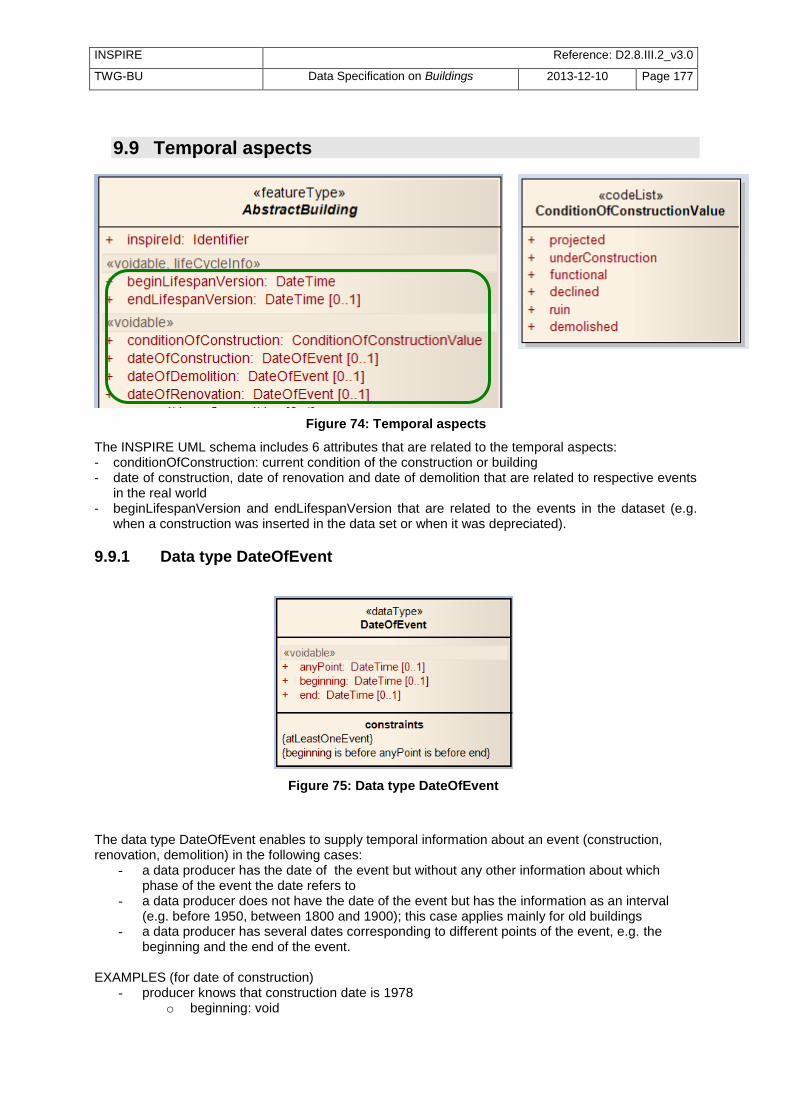
INSPIRE Reference: D2.8.III.2_v3.0
TWG-BU Data Specification on Buildings 2013-12-10 Page 177
9.9 Temporal aspects
Figure 74: Temporal aspects
The INSPIRE UML schema includes 6 attributes that are related to the temporal aspects: - conditionOfConstruction: current condition of the construction or building - date of construction, date of renovation and date of demolition that are related to respective events
in the real world - beginLifespanVersion and endLifespanVersion that are related to the events in the dataset (e.g.
when a construction was inserted in the data set or when it was depreciated).
9.9.1 Data type DateOfEvent
Figure 75: Data type DateOfEvent
The data type DateOfEvent enables to supply temporal information about an event (construction, renovation, demolition) in the following cases:
- a data producer has the date of the event but without any other information about which phase of the event the date refers to
- a data producer does not have the date of the event but has the information as an interval (e.g. before 1950, between 1800 and 1900); this case applies mainly for old buildings
- a data producer has several dates corresponding to different points of the event, e.g. the beginning and the end of the event.
EXAMPLES (for date of construction)
- producer knows that construction date is 1978 o beginning: void

INSPIRE Reference: D2.8.III.2_v3.0
TWG-BU Data Specification on Buildings 2013-12-10 Page 178
o end: void o anyPoint: 1978
- producer knows that construction took place before 1950 o beginning: void o end: 1950 o anyPoint: void
- producer knows that construction took place between 1800 and 1900 o beginning: 1800 o end: 1900 o anyPoint: void
- producer knows that construction took place between 12/04/2008 and 25/12/2010 o beginning: 12/04/2008 o end :25/12/2010 o anyPoint: void
9.9.2 Demolished Buildings There are two ways to deal with demolished constructions or buildings. EXAMPLE: a building that was functional was demolished on 20/03/2010 and this information is integrated by data producer on the 15/05/2010
first method: the building is considered as depreciated (no valid any longer) o its attribute endLifespanVersion gets value ―15/05/2010‖ o its attribute dateOfDemolition gets value ―20/03/2010‖ o the other attributes stay as they are, describing the building as it was just before being
demolished (e.g. its attribute conditionOfConstruction remains ―functional‖)
second method: the building is versioned in the database : o the attribute endLifespanVersion of the old version of the building will get value
―15/05/2010‖ o the attribute dateOfDemolition of the old version remains empty o the other attributes stay as they are, describing the building as it was just before being
demolished (e.g. its attribute conditionOfConstruction remains ―functional‖)
o the attribute beginLifespanVersion of the new version of the building will get value ―15/05/2010‖
o the attribute endLifespanVersion of the new version of the building remains empty o the attribute conditionOfConstruction of the new version will get value “demolished” o the attribute dateOfDemolition of the new version will get value "20/03/2010"
The second method is well adapted for the data sets that aim to manage historical buildings whereas the first one is probably better for data sets that aim to manage current buildings.
9.10 Estimated accuracy For INSPIRE, buildings shall be published in the Coordinate Reference System mandated by the Implementing Rule on Reference Systems, i.e. in ETRS89 for areas on the Eurasian tectonic plate and in ITRS elsewhere. Of course, INSPIRE users will be interested by having information about the accuracy of building data, as they receive them, in the Coordinate Reference System mandated by INSPIRE. It is why the clauses about application schema and about quality and metadata require building data providers to give estimated accuracy related to the coordinates in ETRS89 (or ITRS).

INSPIRE Reference: D2.8.III.2_v3.0
TWG-BU Data Specification on Buildings 2013-12-10 Page 179
However, in most Member States, the estimated accuracy is generally known in the source Coordinate Reference System, the national or local one. The estimated accuracy for INSPIRE will be the combination of estimated accuracy in original Coordinate Reference System and of the accuracy of the coordinate transformation between original Reference System to INSPIRE Reference System. Coordinate transformation between two horizontal geodetic datum is generally done, using one of the three following methods:
transformation with 3 parameters
transformation with 7 parameters
transformation with a grid. Experience in some countries has shown that transformation with 3 or even 7 parameters might bring deviations up to 10 metres. So, the impact of such transformations may not be neglected on building data whose original accuracy generally varies from some decimetres to some metres. The ideal solution would be for each Member State to define good quality coordinate transformations (using grids and bringing no deviation bigger than some centimetres). However, if not possible before the deadlines of INSPIRE, the impact of coordinate transformation has to be taken into account when giving information about positional accuracy, both in the application schema and in metadata.
10 Portrayal This clause defines the rules for layers and styles to be used for portrayal of the spatial object types defined for this theme. Portrayal is regulated in Article 14 of the IRs.
IR Requirement Article 14 Portrayal
1. For the portrayal of spatial data sets using a view network service as specified in Commission
Regulation No 976/2009 (16
), the following shall be available: (a) the layers specified in Annex II for the theme or themes the data set is related to; (b) for each layer at least a default portrayal style, with as a minimum an associated title and a
unique identifier. 2. For each layer, Annex II defines the following: (a) a human readable title of the layer to be used for display in user interface;
(b) the spatial object type(s), or sub-set thereof, that constitute(s) the content of the layer.
In section 11.1, the types of layers are defined that are to be used for the portrayal of the spatial object types defined in this specification. A view service may offer several layers of the same type, one for each dataset that it offers data on a specific topic. NOTE The layer specification in the IRs only contains the name, a human readable title and the (subset(s) of) spatial object type(s), that constitute(s) the content of the layer. In addition, these Technical Guidelines suggest keywords for describing the layer.
16
OJ L 274, 20.10.2009, p. 9.
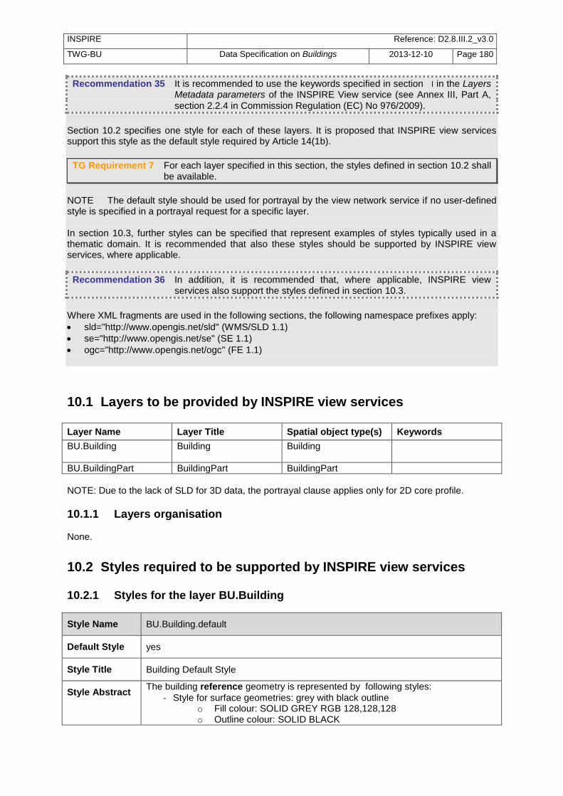
INSPIRE Reference: D2.8.III.2_v3.0
TWG-BU Data Specification on Buildings 2013-12-10 Page 180
Recommendation 35 It is recommended to use the keywords specified in section in the Layers Metadata parameters of the INSPIRE View service (see Annex III, Part A,
section 2.2.4 in Commission Regulation (EC) No 976/2009).
Section 10.2 specifies one style for each of these layers. It is proposed that INSPIRE view services support this style as the default style required by Article 14(1b).
TG Requirement 7 For each layer specified in this section, the styles defined in section 10.2 shall be available.
NOTE The default style should be used for portrayal by the view network service if no user-defined style is specified in a portrayal request for a specific layer. In section 10.3, further styles can be specified that represent examples of styles typically used in a thematic domain. It is recommended that also these styles should be supported by INSPIRE view services, where applicable.
Recommendation 36 In addition, it is recommended that, where applicable, INSPIRE view services also support the styles defined in section 10.3.
Where XML fragments are used in the following sections, the following namespace prefixes apply:
sld="http://www.opengis.net/sld" (WMS/SLD 1.1)
se="http://www.opengis.net/se" (SE 1.1)
ogc="http://www.opengis.net/ogc" (FE 1.1)
10.1 Layers to be provided by INSPIRE view services
Layer Name Layer Title Spatial object type(s) Keywords
BU.Building Building Building
BU.BuildingPart BuildingPart BuildingPart
NOTE: Due to the lack of SLD for 3D data, the portrayal clause applies only for 2D core profile.
10.1.1 Layers organisation None.
10.2 Styles required to be supported by INSPIRE view services
10.2.1 Styles for the layer BU.Building
Style Name BU.Building.default
Default Style yes
Style Title Building Default Style
Style Abstract The building reference geometry is represented by following styles:
- Style for surface geometries: grey with black outline o Fill colour: SOLID GREY RGB 128,128,128 o Outline colour: SOLID BLACK

INSPIRE Reference: D2.8.III.2_v3.0
TWG-BU Data Specification on Buildings 2013-12-10 Page 181
o Outline width: 0,4pt
- Style for point geometries: dark grey circle o Style: CIRCLE o Fill colour: SOLID DARK GREY (RGB 82,82,82) o Width: 10pt
Symbology <sld:NamedLayer> <se:Name>BU.Building</se:Name> <sld:UserStyle> <se:Name>BU.Building.Default</se:Name> <sld:IsDefault>1</sld:IsDefault> <se:FeatureTypeStyle version="1.1.0"> <se:Description> <se:Title>Building default style</se:Title> <se:Abstract/> </se:Description> <se:FeatureTypeName>BU/Buildings2D/Building</se:FeatureTypeName> <Rule> <se:MinScaleDenominator>50</se:MinScaleDenominator> <se:MaxScaleDenominator>25000</se:MaxScaleDenominator> <se:Filter> <se:And> <se:PropertyIsEqualTo> <se:Function name="in2"> <se:Function name="geometryType"> <se:PropertyName>geometry2D/geometry</se:PropertyName> </se:Function> <se:Literal>Polygon</se:Literal> <se:Literal>MultiPolygon</se:Literal> </se:Function> <se:Literal>true</se:Literal> </se:PropertyIsEqualTo> <se:PropertyIsEqualTo> <se:PropertyName>geometry2D/referenceGeometry</se:PropertyName> <se:Literal>true</se:Literal> </se:PropertyIsEqualTo> </se:And> </se:Filter> <se:PolygonSymbolizer> <se:Geometry> <se:PropertyName>geometry2D/geometry</se:PropertyName> </se:Geometry> <se:Fill> <se:SvgParameter name="fill">#808080</se:SvgParameter> </se:Fill> <se:Stroke> <se:SvgParameter name="stroke">#000000</se:SvgParameter> <se:SvgParameter name="strokewidth"> 0.4</se:SvgParameter> </se:Stroke> </se:PolygonSymbolizer> </Rule> <Rule> <se:MinScaleDenominator>50</se:MinScaleDenominator> <se:MaxScaleDenominator>25000</se:MaxScaleDenominator> <se:Filter> <se:And>

INSPIRE Reference: D2.8.III.2_v3.0
TWG-BU Data Specification on Buildings 2013-12-10 Page 182
<se:PropertyIsEqualTo> <se:Function name="in2"> <se:Function name="geometryType"> <se:PropertyName>geometry2D/geometry</se:PropertyName> </se:Function> <se:Literal>Point</se:Literal> <se:Literal>MultiPoint</se:Literal> </se:Function> <se:Literal>true</se:Literal> </se:PropertyIsEqualTo> <se:PropertyIsEqualTo> <se:PropertyName>geometry2D/referenceGeometry</se:PropertyName> <se:Literal>true</se:Literal> </se:PropertyIsEqualTo> </se:And> </se:Filter> <se:PointSymbolizer> <se:Geometry> <se:PropertyName>geometry2D/geometry</se:PropertyName> </se:Geometry> <se:Graphic> <se:Mark> <se:WellKnownName>circle</se:WellKnownName> <se:Fill> <se:SvgParameter name="fill">#525252</se:SvgParameter> </se:Fill> </se:Mark> <se:Size> <se:SvgParameter> name="size">10</se:SvgParameter> </se:Size> </se:Graphic> </se:PointSymbolizer> </Rule> </se:FeatureTypeStyle> </sld:UserStyle> </sld:NamedLayer>
Minimum & maximum scales
<1/50> - <1/25 000>

INSPIRE Reference: D2.8.III.2_v3.0
TWG-BU Data Specification on Buildings 2013-12-10 Page 183
Scale 1/1000 Scale 1/ 10 000 Point representation
Figure 76: Exemples of Building portrayal
NOTE 1: The scale range enables the user to discover buildings from scale 1/ 25 000 but good
rendering of buildings is generally obtained only at larger scales ( 1/10 000), especially in urban areas.
10.2.2 Styles for the layer BU.BuildingPart
Style Name BU.Building.default
Default Style yes
Style Title BuildingPart Default Style
Style Abstract The building reference geometry is represented by following styles:
- Style for surface geometries: hollow with black outline o Fill colour: TRANSPARENT o Outline colour: SOLID BLACK o Outline width: 0,2pt
- Style for point geometries: grey circles o Style: CIRCLE o Fill colour: SOLID GREY (RGB 128,128,128) o Width: 5pt
Symbology <sld:NamedLayer> <se:Name>BU.BuildingPart</se:Name> <sld:UserStyle> <se:Name>BU.BuildingPart.Default</se:Name> <sld:IsDefault>1</sld:IsDefault> <se:FeatureTypeStyle version="1.1.0"> <se:Description> <se:Title>Building part default style</se:Title> <se:Abstract/> </se:Description> <se:FeatureTypeName>BU/Buildings/BuildingPart</se:FeatureTypeName> <Rule> <se:MinScaleDenominator>50</se:MinScaleDenominator> <se:MaxScaleDenominator>10000</se:MaxScaleDenominator> <se:Filter> <se:And> <se:PropertyIsEqualTo>

INSPIRE Reference: D2.8.III.2_v3.0
TWG-BU Data Specification on Buildings 2013-12-10 Page 184
<se:Function name="in2"> <se:Function name="geometryType"> <se:PropertyName>geometry2D/geometry</se:PropertyName> </se:Function> <se:Literal>Polygon</se:Literal> <se:Literal>MultiPolygon</se:Literal> </se:Function> <se:Literal>true</se:Literal> </se:PropertyIsEqualTo> <se:PropertyIsEqualTo> <se:PropertyName>geometry2D/referenceGeometry</se:PropertyName> <se:Literal>true</se:Literal> </se:PropertyIsEqualTo> </se:And> </se:Filter> <se:PolygonSymbolizer> <se:Geometry> <ogc:PropertyName>geometry2D/geometry</ogc:PropertyName> </se:Geometry> <se:Stroke> <se:SvgParameter name="stroke">#000000</se:SvgParameter> <se:SvgParameter name="strokewidth">0.2</se:SvgParameter> </se:Stroke> </se:PolygonSymbolizer> </Rule> <Rule> <se:MinScaleDenominator>50</se:MinScaleDenominator> <se:MaxScaleDenominator>10000</se:MaxScaleDenominator> <se:Filter> <se:And> <se:PropertyIsEqualTo> <se:Function name="in2"> <se:Function name="geometryType"> <se:PropertyName>geometry2D/geometry</se:PropertyName> </se:Function> <se:Literal>Point</se:Literal> <se:Literal>MultiPoint</se:Literal> </se:Function> <se:Literal>true</se:Literal> </se:PropertyIsEqualTo> <se:PropertyIsEqualTo> <se:PropertyName>geometry2D/referenceGeometry</se:PropertyName> <se:Literal>true</se:Literal> </se:PropertyIsEqualTo> </se:And> </se:Filter> <se:PointSymbolizer> <se:Geometry> <ogc:PropertyName>geometry2D/geometry</ogc:PropertyName> </se:Geometry> <se:Graphic> <se:Mark> <se:WellKnownName>circle</se:WellKnownName> <se:Fill> <se:SvgParameter name="fill">#808080</se:SvgParameter> </se:Fill>

INSPIRE Reference: D2.8.III.2_v3.0
TWG-BU Data Specification on Buildings 2013-12-10 Page 185
</se:Mark> <se:Size> <se:SvgParameter> name="size">5</se:SvgParameter> </se:Size> </se:Graphic> </se:PointSymbolizer> </Rule> </se:FeatureTypeStyle> </sld:UserStyle> </sld:NamedLayer>
Minimum & maximum scales
<1/50> - <1/10 000>
Scale 1/500 Scale 1/500 ; BuildingPart combined with Building Building must be bottom layer BuildingPart must be top layer
Figure 77: Examples of BuildingPart portrayal
NOTE 2: the legend proposed by INSPIRE aims to represent Building and BuildingPart as reference data, with neutral colours. This legend is especially suitable when buildings are represented together with other more coloured layers, such as Land Use, Land Cover, Natural Risk Zones …. More attractive legends to represent theme Buildings alone may/should be proposed by the data providers and are up to them.
10.3 Styles recommended to be supported by INSPIRE view services
None.

INSPIRE Reference: D2.8.III.2_v3.0
TWG-BU Data Specification on Buildings 2013-12-10 Page 186
Bibliography CLASSIFICATION OF TYPES OF CONSTRUCTIONS -Eurostat- 15/10/1997 Creating a global building inventory for earthquake loss assessment and risk management, Open-file Report 2008-1160", US Department if the Interior and US Geological survey, USA.- Jaiswal K., Wals D. (2008) Measurement code for the floor area of buildings – CLGE
DEVELOPING A PRAGMATIC APPROACH TO ASSESS URBAN METABOLISM IN EUROPE]- A Report to the European Environment Agency - Stockholm Environment Institute & Technische Universität Berlin- 2010
Regulation (EC) No 763/2008 of the European Parliament and of the Council on population and housing censuses as regards the technical specifications of the topics and of their breakdowns DIRECTIVE 2002/49/EC OF THE EUROPEAN PARLIAMENT AND OF THE COUNCIL of 25 June 2002 relating to the assessment and management of environmental noise - Official Journal of the European Communities DIRECTIVE 2002/91/EC OF THE EUROPEAN PARLIAMENT AND OF THE COUNCIL of 16 December 2002 on the energy performance of buildings - Official Journal of the European Communities DIRECTIVE 2008/50/EC OF THE EUROPEAN PARLIAMENT AND OF THE COUNCIL of 21 May 2008 on ambient air quality and cleaner air for Europe - Official Journal of the European Communities [DS-D2.3] INSPIRE DS-D2.3, Definition of Annex Themes and Scope, v3.0,
http://inspire.jrc.ec.europa.eu/reports/ImplementingRules/DataSpecifications/D2.3_Definition_of_Annex_Themes_and_scope_v3.0.pdf
[DS-D2.5] INSPIRE DS-D2.5, Generic Conceptual Model, v3.3,
http://inspire.jrc.ec.europa.eu/documents/Data_Specifications/D2.5_v3_3.pdf [DS-D2.6] INSPIRE DS-D2.6, Methodology for the development of data specifications, v3.0,
http://inspire.jrc.ec.europa.eu/reports/ImplementingRules/DataSpecifications/D2.6_v3.0.pdf
[DS-D2.7] INSPIRE DS-D2.7, Guidelines for the encoding of spatial data, v3.2,
http://inspire.jrc.ec.europa.eu/documents/Data_Specifications/D2.7_v3.2.pdf [ISO 19101] EN ISO 19101:2005 Geographic information – Reference model (ISO 19101:2002) [ISO 19103] ISO/TS 19103:2005, Geographic information – Conceptual schema language [ISO 19107] EN ISO 19107:2005, Geographic information – Spatial schema (ISO 19107:2003) [ISO 19108] EN ISO 19108:2005 Geographic information - Temporal schema (ISO 19108:2002) [ISO 19111] EN ISO 19111:2007 Geographic information - Spatial referencing by coordinates (ISO
19111:2007) [ISO 19115] EN ISO 19115:2005, Geographic information – Metadata (ISO 19115:2003) [ISO 19118] EN ISO 19118:2006, Geographic information – Encoding (ISO 19118:2005)

INSPIRE Reference: D2.8.III.2_v3.0
TWG-BU Data Specification on Buildings 2013-12-10 Page 187
[ISO 19135] EN ISO 19135:2007 Geographic information – Procedures for item registration (ISO 19135:2005)
[ISO 19139] ISO/TS 19139:2007, Geographic information – Metadata – XML schema implementation [ISO 19157] ISO/DIS 19157, Geographic information – Data quality [OGC 06-103r3] Implementation Specification for Geographic Information - Simple feature access –
Part 1: Common Architecture v1.2.0
OpenGIS® City Geography Markup Language (CityGML) Encoding Standard v2.0

INSPIRE Reference: D2.8.III.2_v3.0
TWG-BU Data Specification on Buildings 2013-12-10 Page 188
Annex A (normative)
Abstract Test Suite
Disclaimer While this Annex refers to the Commission Regulation (EU) No 1089/2010 of 23 November 2010 implementing Directive 2007/2/EC of the European Parliament and of the Council as regards interoperability of spatial data sets and services, it does not replace the legal act or any part of it.
The objective of the Abstract Test Suite (ATS) included in this Annex is to help the conformance testing process. It includes a set of tests to be applied on a data set to evaluate whether it fulfils the requirements included in this data specification and the corresponding parts of Commission Regulation No 1089/2010 (implementing rule as regards interoperability of spatial datasets and services, further referred to as ISDSS Regulation). This is to help data providers in declaring the conformity of a data set to the ―degree of conformity, with implementing rules adopted under Article 7(1) of Directive 2007/2/EC‖, which is required to be provided in the data set metadata according to Commission Regulation (EC) No 2008/1205 (the Metadata Regulation). Part 1 of this ATS includes tests that provide input for assessing conformity with the ISDSS regulation. In order to make visible which requirements are addressed by a specific test, references to the corresponding articles of the legal act are given. The way how the cited requirements apply to bu specification is described under the testing method. In addition to the requirements included in ISDSS Regulation this Technical guideline contains TG requirements too. TG requirements are technical provisions that need to be fulfilled in order to be conformant with the corresponding IR requirement when the specific technical implementation proposed in this document is used. Such requirements relate for example to the default encoding described in section 9. Part 2 of the ATS presents tests necessary for assessing the conformity with TG requirements. NOTE Conformance of a data set with the TG requirement(s) included in this ATS implies conformance with the corresponding IR requirement(s). The ATS is applicable to the data sets that have been transformed to be made available through INSPIRE download services (i.e. the data returned as a response to the mandatory ―Get Spatial Dataset‖ operation) rather than the original ―source‖ data sets. The requirements to be tested are grouped in several conformance classes. Each of these classes covers a specific aspect: one conformance class contains tests reflecting the requirements on the application schema, another on the reference systems, etc. Each conformance class is identified by a URI (uniform resource identifier) according to the following pattern: http://inspire.ec.europa.eu/conformance-class/ir/bu/<conformance class identifier> EXAMPLE 1 The URI http://inspire.ec.europa.eu/conformance-class/ir/ef/rs identifies the Reference Systems ISDSS conformance class of the Environmental Monitoring Facilities (EF) data theme. The results of the tests should be published referring to the relevant conformance class (using its URI). When an INSPIRE data specification contains more than one application schema, the requirements tested in a conformance class may differ depending on the application schema used as a target for the transformation of the data set. This will always be the case for the application schema conformance class. However, also other conformance classes could have different requirements for different

INSPIRE Reference: D2.8.III.2_v3.0
TWG-BU Data Specification on Buildings 2013-12-10 Page 189
application schemas. In such cases, a separate conformance class is defined for each application schema, and they are distinguished by specific URIs according to the following pattern: http://inspire.ec.europa.eu/conformance-class/ir/bu/<conformance class identifier>/ <application schema namespace prefix> EXAMPLE 2 The URI http://inspire.ec.europa.eu/conformance-class/ir/el/as/el-vec identifies the conformity with the application schema (as) conformance class for the Elevation Vector Elements (el-vec) application schema. An overview of the conformance classes and the associated tests is given in the table below.
A.1 Application Schema Conformance Class ............................................................................. 191 A.1.1 Schema element denomination test .............................................................................. 191 A.1.2 Value type test ............................................................................................................... 191 A.1.3 Value test ....................................................................................................................... 191 A.1.4 Attributes/associations completeness test ..................................................................... 192 A.1.5 Abstract spatial object test ............................................................................................. 192 A.1.6 Constraints test .............................................................................................................. 192 A.1.7 Geometry representation test ........................................................................................ 192
A.2 Reference Systems Conformance Class .............................................................................. 193 A.2.1 Datum test ...................................................................................................................... 193 A.2.2 Coordinate reference system test .................................................................................. 193 A.2.3 View service coordinate reference system test ............................................................. 194 A.2.4 Temporal reference system test .................................................................................... 194 A.2.5 Units of measurements test ........................................................................................... 194
A.3 Data Consistency Conformance Class ................................................................................. 194 A.3.1 Unique identifier persistency test ................................................................................... 195 A.3.2 Version consistency test ................................................................................................ 195 A.3.3 Life cycle time sequence test ......................................................................................... 195 A.3.4 Update frequency test .................................................................................................... 195
A.4 Metadata IR Conformance Class .......................................................................................... 196 A.5.1 Metadata for interoperability test ................................................................................... 196
A.5 Information Accessibility Conformance Class ....................................................................... 196 A.6.1 Code list publication test ................................................................................................ 196 A.6.2 CRS publication test ...................................................................................................... 196 A.6.3 CRS identification test ................................................................................................... 196
A.6 Data Delivery Conformance Class ........................................................................................ 197 A.6.1 Encoding compliance test .............................................................................................. 197
A.7 Portrayal Conformance Class ............................................................................................... 197 A.8.1 Layer designation test .................................................................................................... 197
A.8 Technical Guideline Conformance Class .............................................................................. 198 A.8.1 Multiplicity test................................................................................................................ 198 A.9.1 CRS http URI test .......................................................................................................... 198 A.9.2 Metadata encoding schema validation test ................................................................... 198 A.9.3 Metadata occurrence test .............................................................................................. 198 A.9.4 Metadata consistency test ............................................................................................. 199 A.9.5 Encoding schema validation test ................................................................................... 199 A.9.6 Style test ........................................................................................................................ 199
In order to be conformant to a conformance class, a data set has to pass all tests defined for that conformance class. In order to be conformant with the ISDSS regulation the inspected data set needs to be conformant to all conformance classes in Part 1. The conformance class for overall conformity with the ISDSS regulation is identified by the URI http://inspire.ec.europa.eu/conformance-class/ir/bu/.

INSPIRE Reference: D2.8.III.2_v3.0
TWG-BU Data Specification on Buildings 2013-12-10 Page 190
In order to be conformant with the Technical Guidelines, the dataset under inspection needs to be conformant to all conformance classes included both in Part 1 and 2. Chapter 8 describes in detail how to publish the result of testing regarding overall conformity and conformity with the conformance classes as metadata. The conformance class for overall conformity with the Technical Guidelines is identified by the URI http://inspire.ec.europa.eu/conformance-class/tg/bu/3.0. It should be noted that data providers are not obliged to integrate / decompose the original structure of the source data sets when they deliver them for INSPIRE. It means that a conformant dataset can contain less or more spatial object / data types than specified in the ISDSS Regulation. A dataset that contains less spatial object and/or data types can be regarded conformant when the corresponding types of the source datasets after the necessary transformations fulfil the requirements set out in the ISDSS Regulation. A dataset that contain more spatial object and/or data types may be regarded as conformant when - all the spatial object / data types that have corresponding types in the source dataset after the
necessary transformations fulfil the requirements set out in the ISDSS Regulation and - all additional elements of the source model (spatial object types, data types, attributes,
constraints, code lists and enumerations together with their values) do not conflict with any rule defined in the interoperability target specifications defined for any theme within INSPIRE.
Open issue 2: Even though the last condition can be derived from Art. 8(4) of the Directive, the ISDSS Regulation does not contain requirements concerning the above issue. Therefore, no specific tests have been included in this abstract suit for testing conformity of extended application schemas. Annex F of the Generic Conceptual Model (D2.5) provides an example how to extend INSPIRE application schemas in a compliant way.
The ATS contains a detailed list of abstract tests. It should be noted that some tests in the Application schema conformance class can be automated by utilising xml schema validation tools. It should be noted that failing such validation test does not necessary reflect non-compliance to the application schema; it may be the results of erroneous encoding. Each test in this suit follows the same structure:
Requirement: citation from the legal texts (ISDSS requirements) or the Technical Guidelines (TG requirements);
Purpose: definition of the scope of the test;
Reference: link to any material that may be useful during the test;
Test method: description of the testing procedure. According to ISO 19105:2000 all tests in this ATS are basic tests. Therefore, this statement is not repeated each time.

INSPIRE Reference: D2.8.III.2_v3.0
TWG-BU Data Specification on Buildings 2013-12-10 Page 191
Part 1 (normative)
Conformity with Commission Regulation No 1089/2010
A.1 Application Schema Conformance Class Conformance classes: http://inspire.ec.europa.eu/conformance-class/ir/bu/as/BuildingsBase http://inspire.ec.europa.eu/conformance-class/ir/bu/as/Buildings2D http://inspire.ec.europa.eu/conformance-class/ir/bu/as/Buildings3D
A.1.1 Schema element denomination test
a) Purpose: Verification whether each element of the dataset under inspection carries a name specified in the target application schema(s). b) Reference: Art. 3 and Art.4 of Commission Regulation No 1089/2010 c) Test Method: Examine whether the corresponding elements of the source schema (spatial object types, data types, attributes, association roles, code lists, and enumerations) are mapped to the target schema with the correct designation of mnemonic names. NOTE Further technical information is in the Feature catalogue and UML diagram of the application schema(s) in sections 5.2, 5.3 and 5.4.
A.1.2 Value type test
a) Purpose: Verification whether all attributes or association roles use the corresponding value types specified in the application schema(s). b) Reference: Art. 3, Art.4, Art.6(1), Art.6(4), Art.6(5) and Art.9(1)of Commission Regulation No 1089/2010. c) Test Method: Examine whether the value type of each provided attribute or association role adheres to the corresponding value type specified in the target specification. NOTE 1 This test comprises testing the value types of INSPIRE identifiers, the value types of attributes and association roles that should be taken from enumeration and code lists, and the coverage domains. NOTE 2 Further technical information is in the Feature catalogue and UML diagram of the application schema(s) in sections 5.2, 5.3 and 5.4.
A.1.3 Value test
a) Purpose: Verify whether all attributes or association roles whose value type is a code list or enumeration take the values set out therein. b) Reference: Art.4 (3) of Commission Regulation No 1089/2010. c) Test Method: When an attributes / association roles has ―enumeration‖ or ―codeList‖ type compare the values of each instance with those provided in the application schema. To pass this tests any instance of an attribute / association role
Shall not take any other value than defined in the enumeration table when its type is enumeration.
Shall take only values explicitly specified in the code list when its type is codeList with extensibility value is ―none‖.

INSPIRE Reference: D2.8.III.2_v3.0
TWG-BU Data Specification on Buildings 2013-12-10 Page 192
Shall take only a value explicitly specified in the code list or shall take a value that is narrower (i.e. more specific) than those explicitly specified in the application schema when the type is codeList with extensibility value is ―narrower‖.
NOTE 1 This test is not applicable to code lists with extensibility ―any‖. NOTE 2 When a data provider only uses code lists with narrower (more specific values) this test can be fully performed based on internal information.
A.1.4 Attributes/associations completeness test
a) Purpose: Verification whether each instance of spatial object type and data types include all attributes and association roles as defined in the target application schema. b) Reference: Art. 3, Art.4(1), Art.4(2), and Art.5(2) of Commission Regulation No 1089/2010. c) Test Method: Examine whether all attributes and association roles defined for a spatial object type or data type are present for each instance in the dataset. NOTE 1 Further technical information is in the Feature catalogue and UML diagram of the application schema(s) in sections 5.2, 5.3 and 5.4. NOTE 2 If an attribute has the stereotype «voidable», then according to the INSPIRE Generic Conceptual Model (section 9.8.4.3) one of the three ―void reason‖ values ―unknown‖, ―unpopulated‖ or ―withheld‖ shall be provided instead of the real values. NOTE 3 If the characteristic described by the attribute or association role does not apply to the real world entity, the attribute or association role does not need to be present in the data set.
A.1.5 Abstract spatial object test
a) Purpose: Verification whether the dataset does NOT contain abstract spatial object / data types defined in the target application schema(s). b) Reference: Art.5(3) of Commission Regulation No 1089/2010 c) Test Method: examine that there are NO instances of abstract spatial object / data types in the dataset provided. NOTE Further technical information is in the Feature catalogue and UML diagram of the application schema(s) in sections 5.2, 5.3 and 5.4.
A.1.6 Constraints test
a) Purpose: Verification whether the instances of spatial object and/or data types provided in the dataset adhere to the constraints specified in the target application schema(s). b) Reference: Art. 3, Art.4(1), and Art.4(2) of Commission Regulation No 1089/2010. c) Test Method: Examine all instances of data for the constraints specified for the corresponding spatial object / data type. Each instance shall adhere to all constraints specified in the target application schema(s). NOTE Further technical information is in the Feature catalogue and UML diagram of the application schema(s) in sections 5.2, 5.3 and 5.4.
A.1.7 Geometry representation test
a) Purpose: Verification whether the value domain of spatial properties is restricted as specified in the Commission Regulation No 1089/2010.

INSPIRE Reference: D2.8.III.2_v3.0
TWG-BU Data Specification on Buildings 2013-12-10 Page 193
b) Reference: Art.12(1), Annex IV Section 2 of Commission Regulation No 1089/2010 c) Test Method: Check whether all spatial properties only use 0, 1 and 2-dimensional geometric objects that exist in the right 2-, 3- or 4-dimensional coordinate space, and where all curve interpolations respect the rules specified in the reference documents. NOTE 1 Further technical information is in OGC Simple Feature spatial schema v1.2.1 [06-103r4]. NOTE 2 This test does not apply for the 3D application schema since the OGC Simple Feature spatial schema is not relevant.
A.2 Reference Systems Conformance Class Conformance class: http://inspire.ec.europa.eu/conformance-class/ir/bu/rs
A.2.1 Datum test
a) Purpose: Verify whether each instance of a spatial object type is given with reference to one of the (geodetic) datums specified in the target specification. c) Reference: Annex II Section 1.2 of Commission Regulation No 1089/2010 b) Test Method: Check whether each instance of a spatial object type specified in the application schema(s) in section 5 has been expressed using:
the European Terrestrial Reference System 1989 (ETRS89) within its geographical scope; or
the International Terrestrial Reference System (ITRS) for areas beyond the ETRS89 geographical scope; or
other geodetic coordinate reference systems compliant with the ITRS. Compliant with the ITRS means that the system definition is based on the definition of ITRS and there is a well-established and described relationship between both systems, according to the EN ISO 19111.
NOTE Further technical information is given in Section 6 of this document.
A.2.2 Coordinate reference system test
a) Purpose: Verify whether the two- and three-dimensional coordinate reference systems are used as defined in section 6. b) Reference: Section 6 of Commission Regulation 1089/2010. c) Test Method: Inspect whether the horizontal and vertical components of coordinates one of the corresponding coordinate reference system has been:
Three-dimensional Cartesian coordinates based on a datum specified in 1.2 and using the parameters of the Geodetic Reference System 1980 (GRS80) ellipsoid.
Three-dimensional geodetic coordinates (latitude, longitude and ellipsoidal height) based on a datum specified in 1.2 and using the parameters of the GRS80 ellipsoid.
Two-dimensional geodetic coordinates (latitude and longitude) based on a datum specified in 1.2 and using the parameters of the GRS80 ellipsoid.
Plane coordinates using the ETRS89 Lambert Azimuthal Equal Area coordinate reference system.
Plane coordinates using the ETRS89 Lambert Conformal Conic coordinate reference system.
Plane coordinates using the ETRS89 Transverse Mercator coordinate reference system.
For the vertical component on land, the European Vertical Reference System (EVRS) shall be used to express gravity-related heights within its geographical scope. Other vertical reference systems related to the Earth gravity field shall be used to express gravity-related heights in areas that are outside the geographical scope of EVRS.

INSPIRE Reference: D2.8.III.2_v3.0
TWG-BU Data Specification on Buildings 2013-12-10 Page 194
For the vertical component in marine areas where there is an appreciable tidal range (tidal waters), the Lowest Astronomical Tide (LAT) shall be used as the reference surface.
For the vertical component in marine areas without an appreciable tidal range, in open oceans and effectively in waters that are deeper than 200 meters, the Mean Sea Level (MSL) or a well-defined reference level close to the MSL shall be used as the reference surface.―
For the vertical component in the free atmosphere, barometric pressure, converted to height using ISO 2533:1975 International Standard Atmosphere, or other linear or parametric reference systems shall be used. Where other parametric reference systems are used, these shall be described in an accessible reference using EN ISO 19111-2:2012.
NOTE Further technical information is given in Section 6 of this document.
A.2.3 View service coordinate reference system test
a) Purpose: Verify whether the spatial data set is available in the two dimensional geodetic coordinate system for their display with the INSPIRE View Service. b) Reference: Annex II Section 1.4 of Commission Regulation 1089/2010 c) Test Method: Check that each instance of a spatial object types specified in the application schema(s) in section 5 is available in the two-dimensional geodetic coordinate system NOTE Further technical information is given in Section 6 of this document.
A.2.4 Temporal reference system test
a) Purpose: Verify whether date and time values are given as specified in Commission Regulation No 1089/2010. b) Reference: Art.11(1) of Commission Regulation 1089/2010 c) Test Method: Check whether:
the Gregorian calendar is used as a reference system for date values;
the Universal Time Coordinated (UTC) or the local time including the time zone as an offset from UTC are used as a reference system for time values.
NOTE Further technical information is given in Section 6 of this document.
A.2.5 Units of measurements test
a) Purpose: Verify whether all measurements are expressed as specified in Commission Regulation No 1089/2010. b) Reference: Art.12(2) of Commission Regulation 1089/2010 c) Test Method: Check whether all measurements are expressed in SI units or non-SI units accepted for use with the International System of Units. NOTE 1 Further technical information is given in ISO 80000-1:2009. NOTE 2 Degrees, minutes and seconds are non-SI units accepted for use with the International System of Units for expressing measurements of angles.
A.3 Data Consistency Conformance Class Conformance class: http://inspire.ec.europa.eu/conformance-class/ir/bu/dc/BuildingsBase http://inspire.ec.europa.eu/conformance-class/ir/bu/dc/Buildings2D http://inspire.ec.europa.eu/conformance-class/ir/bu/dc/Buildings3D

INSPIRE Reference: D2.8.III.2_v3.0
TWG-BU Data Specification on Buildings 2013-12-10 Page 195
A.3.1 Unique identifier persistency test
a) Purpose: Verify whether the namespace and localId attributes of the external object identifier remain the same for different versions of a spatial object. b) Reference: Art. 9 of Commission Regulation 1089/2010. c) Test Method: Compare the namespace and localId attributes of the external object identifiers in the previous version(s) of the dataset with the namespace and localId attributes of the external object identifiers of current version for the same instances of spatial object / data types; To pass the test, neither the namespace, nor the localId shall be changed during the life-cycle of a spatial object. NOTE 1 The localId test can be performed entirely on the basis of the information available in the database of the data providers. NOTE 2 When using URI this test includes the verification whether no part of the construct has been changed during the life cycle of the instances of spatial object / data types. NOTE 3 Further technical information is given in section 14.2 of the INSPIRE Generic Conceptual Model.
A.3.2 Version consistency test
a) Purpose: Verify whether different versions of the same spatial object / data type instance belong to the same type. b) Reference: Art. 9 of Commission Regulation 1089/2010. c) Test Method: Compare the types of different versions for each instance of spatial object / data type NOTE 1 This can be performed entirely on the basis of the information available in the database of the data providers.
A.3.3 Life cycle time sequence test
a) Purpose: Verification whether the value of the attribute beginLifespanVersion refers to an earlier moment of time than the value of the attribute endLifespanVersion for every spatial object / object type where this property is specified. b) Reference: Art.10(3) of Commission Regulation 1089/2010. c) Test Method: Compare the value of the attribute beginLifespanVersion with attribute endLifespanVersion. The test is passed when the beginLifespanVersion value is before endLifespanVersion value for each instance of all spatial object/data types for which this attribute has been defined. NOTE 1 this test can be performed entirely on the basis of the information available in the database of the data providers.
A.3.4 Update frequency test
a) Purpose: Verify whether all the updates in the source dataset(s) have been transmitted to the dataset(s) which can be retrieved for the bu using INSPIRE download services. b) Reference: Art.8 (2) of Commission Regulation 1089/2010. c) Test Method: Compare the values of beginning of life cycle information in the source and the target datasets for each instance of corresponding spatial object / object types. The test is passed when the difference between the corresponding values is less than 6 months.

INSPIRE Reference: D2.8.III.2_v3.0
TWG-BU Data Specification on Buildings 2013-12-10 Page 196
NOTE 1 this test can be performed entirely on the basis of the information available in the database of the data providers.
A.4 Metadata IR Conformance Class Conformance class: http://inspire.ec.europa.eu/conformance-class/ir/bu/md
A.5.1 Metadata for interoperability test
a) Purpose: Verify whether the metadata for interoperability of spatial data sets and services described in 1089/2010 Commission Regulation have been created and published for each dataset related to the BU data theme. b) Reference: Art.13 of Commission Regulation 1089/2010 c) Test Method: Inspect whether metadata describing the coordinate reference systems, temporal reference system, encoding, character encoding and when applicable topological consistency have been created and published. NOTE Further technical information is given in section 8 of this document.
A.5 Information Accessibility Conformance Class Conformance class: http://inspire.ec.europa.eu/conformance-class/ir/bu/ia
A.6.1 Code list publication test
a) Purpose: Verify whether the values of each code list that allow narrower values or any other value than specified in Commission Regulation 1089/2010 are published in a register. b) Reference: Art.6(3) b) Reference: Art.6(3) and Annex IV Section 2. NOTE Further technical information is given in section 5 of this document.
A.6.2 CRS publication test
a) Purpose: Verify whether the identifiers and the parameters of coordinate reference system are published in common registers. b) Reference: Annex II Section 1.5
c) Test method: Check whether the identifier and the parameter of the CRS used for the dataset are included in a register. . NOTE Further technical information is given in section 6 of this document.
A.6.3 CRS identification test
a) Purpose: Verify whether identifiers for other coordinate reference systems than specified in Commission Regulation 1089/2010 have been created and their parameters have been described according to EN ISO 19111 and ISO 19127. b) Reference: Annex II Section 1.3.4
c) Test method: Check whether the register with the identifiers of the coordinate reference systems is accessible.

INSPIRE Reference: D2.8.III.2_v3.0
TWG-BU Data Specification on Buildings 2013-12-10 Page 197
NOTE Further technical information is given in section 6 of this document.
A.6 Data Delivery Conformance Class Conformance class: http://inspire.ec.europa.eu/conformance-class/ir/bu/de
A.6.1 Encoding compliance test
a) Purpose: Verify whether the encoding used to deliver the dataset comply with EN ISO 19118. b) Reference: Art.7 (1) of Commission Regulation 1089/2010. c) Test Method: Follow the steps of the Abstract Test Suit provided in EN ISO 19118. NOTE 1 Datasets using the default encoding specified in Section 9 fulfil this requirement. NOTE 2 Further technical information is given in Section 9 of this document.
A.7 Portrayal Conformance Class Conformance class: http://inspire.ec.europa.eu/conformance-class/ir/bu/po
A.8.1 Layer designation test
a) Purpose: verify whether each spatial object type has been assigned to the layer designated according to Commission Regulation 1089/2010. b) Reference: Art. 14(1), Art14(2) and Annex IV Section 2. c) Test Method: Check whether data is made available for the view network service using the specified layers respectively:
BU.Building
BU.BuildingPart NOTE Further technical information is given in section 11 of this document.

INSPIRE Reference: D2.8.III.2_v3.0
TWG-BU Data Specification on Buildings 2013-12-10 Page 198
Part 2 (informative)
Conformity with the technical guideline (TG) Requirements
A.8 Technical Guideline Conformance Class Conformance classes: http://inspire.ec.europa.eu/conformance-class/tg/bu/3.0
A.8.1 Multiplicity test
a) Purpose: Verify whether each instance of an attribute or association role specified in the application schema(s) does not include fewer or more occurrences than specified in section 5. c) Reference: Feature catalogue and UML diagram of the application schema(s) in section 5 of this guideline. b) Test Method: Examine that the number of occurrences of each attribute and/or association role for each instance of a spatial object type or data type provided in the dataset corresponds to the number of occurrences of the attribute / association role that is specified in the application schema(s) in section 5.
A.9.1 CRS http URI test
a) Purpose: Verify whether the coordinate reference system used to deliver data for INSPIRE network services has been identified by URIs according to the EPSG register. c) Reference: Table 2 in Section 6 of this technical guideline b) Test Method: Compare the URI of the dataset with the URIs in the table. NOTE 1 Passing this test implies the fulfilment of test A6.2 NOTE 2 Further reference please see http://www.epsg.org/geodetic.html
A.9.2 Metadata encoding schema validation test
a) Purpose: Verify whether the metadata follows an XML schema specified in ISO/TS 19139. c) Reference: Section 8 of this technical guideline, ISO/TS 19139 b) Test Method: Inspect whether provided XML schema is conformant to the encoding specified in ISO 19139 for each metadata instance. NOTE 1 Section 2.1.2 of the Metadata Technical Guidelines discusses the different ISO 19139 XML schemas that are currently available.
A.9.3 Metadata occurrence test
a) Purpose: Verify whether the occurrence of each metadata element corresponds to those specified in section 8.
c) Reference: Section 8 of this technical guideline b) Test Method: Examine the number of occurrences for each metadata element. The number of occurrences shall be compared with its occurrence specified in Section 8:

INSPIRE Reference: D2.8.III.2_v3.0
TWG-BU Data Specification on Buildings 2013-12-10 Page 199
NOTE 1 Section 2.1.2 of the Metadata Technical Guidelines discusses the different ISO 19139 XML schema.
A.9.4 Metadata consistency test
a) Purpose: Verify whether the metadata elements follow the path specified in ISO/TS 19139. c) Reference: Section 8 of this technical guideline, ISO/TS 19139 b) Test Method: Compare the XML schema of each metadata element with the path provide in ISO/TS 19137. NOTE 1 This test does not apply to the metadata elements that are not included in ISO/TS 19139.
A.9.5 Encoding schema validation test
a) Purpose: Verify whether the provided dataset follows the rules of default encoding specified in section 9 of this document c) Reference: section 9 of this technical guideline b) Test Method: Inspect whether provided encoding(s) is conformant to the encoding(s) for the relevant application schema(s) as defined in section 9: NOTE 1 Applying this test to the default encoding schema described in section 9 facilitates testing conformity with the application schema specified in section 5. In such cases running this test with positive result may replace tests from A1.1 to A1.4 provided in this abstract test suite. NOTE 2 Using Schematron or other schema validation tool may significantly improve the validation process, because some some complex constraints of the schema cannot be validated using the simple XSD validation process. On the contrary to XSDs Schematron rules are not delivered together with the INSPIRE data specifications. Automating the process of validation (e.g. creation of Schematron rules) is therefore a task and an opportunity for data providers.
A.9.6 Style test
a) Purpose: Verify whether the styles defined in section 11.2 have been made available for each specified layer. b) Reference: section 11.2. c) Test Method: Check whether the styles defined in section 11.2 have been made available for each specified layer.

INSPIRE Reference: D2.8.III.2_v3.0
TWG-BU Data Specification on Buildings 2013-12-10 Page 200
Annex B (informative) Use cases
Table of content
B.1 Common use of building data 201 B.1.1 Modelling of physical phenomena 201 B.1.2 Computation of population in an area of interest 203 B.1.3 Large scale 2D mapping 206 B.1.4 Deriving medium scale data 208 B.1.5 3D models 210
B.2 Safety 212 B.2.1 Travel security 212 B.2.2 Risk assessment 214 B.2.3 Risk management 217
B.3 Urban expansion 219 B.3.1 Integrated urban monitoring 219 B.3.2 Urban planning 223 B.3.3 Urban monitoring 226
B.4 Environment 228 B.4.1 Noise 228 B.4.2 Air quality 230 B.4.3 Soil 230 B.4.4 Energy / Sustainable buildings 232 B.4.5 Quality of habitat 236 B.4.6 Buildings with historical or architectural interest 238
B.5 Infrastructures 240 B.5.1 Location of a new service/activity 240 B.5.2 Management of service/activity 244 B.5.3 Management / valorisation of public patrimony 246
B.6 Census 247 B.6.1 European Census 247 B.6.2 Census Units 249
The use cases presented below are based on real applications, investigated by TWG BU but are projected in future, once INSPIRE conformant data is available. Building data is used in a similar way by different application domains. This is addressed in chapter B1. Domain-specific applications are addressed in following chapters B2, B3 …. The description of the use case is kept short and focuses on the role of building data; it does not aim to provide exhaustive explanations about the use case. The information required by the use cases and provided from INSPIRE theme BU is highlighted in green. Information provided from other themes is highlighted in orange. The purpose of this annex is to show the use cases that have been considered by TWG BU. It provides the rationale of the data specifications and guidelines about how INSPIRE conformant data might/should be used.

INSPIRE Reference: D2.8.III.2_v3.0
TWG-BU Data Specification on Buildings 2013-12-10 Page 201
B.1 Common use of building data
B.1.1 Modelling of physical phenomena
Part 1: UML use case diagram
uc Modelling of physical phenomena
Universities, research
Modelling of physical
phenomena
Local governments
Urban planners
Spatial planning agencies
European Stakeholders
European Environmental
Agency
European Spatial Agency
National/local environmental
agencies Use Use case diagram for modelling of physical phenomena
Part 2: Narrative explanation of the use case Buildings may influence the propagation of physical phenomena, such as air circulation (air pollution, winds), light, water (flood), noise … Data about buildings will be necessary as input for propagation models.
Principle of propagation model

INSPIRE Reference: D2.8.III.2_v3.0
TWG-BU Data Specification on Buildings 2013-12-10 Page 202
Extract of fire forecast on Europe (EFFIS)
Part 3: Detailed, structured description of the use case
Use Case Description
Name Modelling of physical phenomena
Priority high
Description The purpose is to estimate the extent of a physical phenomena, taking into account the influence of buildings on the propagation of the phenomena
Pre-condition
Data related to physical phenomena is available (e.g. hydrography for flood, atmospheric conditions for air circulation). Other necessary topographic data is available (e.g. elevation). A propagation model exists, either as an automatic tool or as a well-defined methodology.
Flow of Events – Basic Path
Step 1. Download INSPIRE topographic data (mainly themes BU, EL) and themes related to physical phenomena (e.g. MF, AC, TN, HY, …)
Step 2
Make a 3D model of landscape using elevation data, preferably as DTM and 3D solid geometry of buildings. Environmental barriers (e.g. dam or embankment for flood, tunnels or acoustic fence for noise, protectiveStructure for rock falling) have to be integrated to this model
Step 3
Possibly, enrich the 3D model by information related to the architecture of the building, such as material of roof / structure /façade, height or number of floors below ground … which may influence the propagation of physical phenomena
Step 4. The landscape 3D model is supplied as input in the propagation model. The propagation model runs and provides the extend of physical phenomena at a given time
Flow of Events – Alternative Paths
Step 2 bis.
The 3D model may be computed using the polygon geometry of buildings and their height above ground or number of floor above ground or floor distribution If available, the 3D model may use shape of roof to refine the 3D representation of buildings
Step 3 bis
If not available, the information related to the architecture of building may be roughly assessed from temporal attributes, date of construction and date of renovation. Domain expertise is required.

INSPIRE Reference: D2.8.III.2_v3.0
TWG-BU Data Specification on Buildings 2013-12-10 Page 203
B.1.2 Computation of population in an area of interest
Part 1: UML use case diagram
pkg Computation of population
:Eurostat
:Local governments
:National/local environmental
agencies
Computation of population
Spatial planning agencies
National statistical agencies
Use case diagram for computation of population
Part 2: Narrative explanation of the use case Statistical data, such as number and characteristics of inhabitants, are available on statistic units. However, many applications require getting an assessment of the number of inhabitants, not on statistical units, but in the area of interest of the application. Typical example is the necessity to assess and report population at day and/or at night located in an area of risk (flood, forest fire, earthquake …) or of pollution (noise, air pollution). It is also necessary to assess the number of inhabitants that will benefit from a new public equipment; for instance, when implementing a new line of public transport, it will be of great interest to estimate how many people are located near the new transport stops.
Statistical data on statistical units Statistical data on area of interest
Principle of computation of population in an area of interest Part 3: Detailed, structured description of the use case Assessment of population at night
Use Case Description
Name Assessment of population at night
Priority high
Description The purpose is to estimate the number of inhabitants during night in an area of interest, for instance an area concerned by noise or air pollution.
Pre-condition The area of interest is known. Statistical data on population are available on statistical units.
Flow of Events – Basic Path
Step 1. Download INSPIRE themes BU and SU - PD
Step 2 Within the area of interest, using attribute current use, select residential buildings. These are the buildings where most people are located at night.

INSPIRE Reference: D2.8.III.2_v3.0
TWG-BU Data Specification on Buildings 2013-12-10 Page 204
Use Case Description
Step 3
Compute the total area of each building dedicated to residential purpose:
- from polygon geometry, compute ground area - total area = ground area x number of floors x percentage of
residential use (if known)
Step 4. For each statistical unit, compute the total area of all buildings
Step 5 Compute the number of inhabitants in each building Number of inhabitant (building X) = (number of inhabitants (SU)/ total area of all buildings in SU) x total area of the building
Step 6. Add the number of inhabitants of all buildings located in the area of interest. This number assesses the population at night.
Flow of Events – Alternative Paths
Step 3 bis.
The total area of each building may be assessed by different ways: - the number of floors may be assessed from the height above
ground - if available, the official area may be used
Step 3 ter In case the percentage of current use is unknown, the use case will use total area instead of total area dedicated to residential purpose..
Step 3 quatro.
Instead of the total area of building, the computation may be done using the volume of building. This volume may be supplied by ground area (from polygon geometry) x height above ground
Result The assessment of population at night is used to implement local management (e.g. schedule rescue services at night) or for reporting (e.g. noise or air pollution)
Data source: <Name> [repeat per data source]
Description INSPIRE themes SU, PD, BU
Geographic scope Area of interest, anywhere in Europe
Assessing population at day
Use Case Description
Name Assessment of population at day
Priority high
Description The purpose is to estimate the number of inhabitants during day in an area of interest.
Pre-condition The area of interest is known. Statistical data on population are available on statistical units. Some domain expertise is required.
Flow of Events – Basic Path
Step 1. Download INSPIRE themes BU, US and SU - PD
Step 2
Assess population in residential buildings. The method is similar to the method described in B1.2.1 but the number of inhabitants has to be replaced by the number of inhabitants staying at home. It is up to domain expertise to decide which method is better:
- apply a percentage - restrict the number of inhabitants according to selection criteria
(age, type of job, …) It may also vary according hours in the day.

INSPIRE Reference: D2.8.III.2_v3.0
TWG-BU Data Specification on Buildings 2013-12-10 Page 205
Use Case Description
Step 3
Assess population in industrial or buildings. Using attribute current Use, select industrial buildings. Compute total area of industrial buildings (same method as for residential buildings). Apply an average rate of occupation to assess the number of people within industrial buildings.
Step 4.
Assess population in office buildings. Using attribute current Use, select office buildings. Compute total area of office buildings (same method as for residential buildings). Apply an average rate of occupation (e.g. 4 persons / 100 m
2) to assess
the number of people within office buildings.
Step 5
Assess population in commercial buildings. Using attribute current Use, select trade buildings. Compute total area of industrial buildings (same method as for residential buildings). Apply an average rate of occupation to assess the number of people within office buildings.
Step 6.
Assess population in public services. This may be done using attribute occupancy of Governmental services in theme US. Using attribute service hours, the information may be refined according day in the week and/or hour in the day.
Flow of Events – Alternative Paths
Step 3 bis
Download data from theme PF. Information about the activity hosted by the buildings within a PF may enable domain expert to make more detailed assessment of the number of occupants the industrial buildings.
Step 3, 4, 5 bis.
A local or national information system on economic activities exist and may be linked to their location in buildings, using :
- common address - or the attribute external reference of theme BU
The knowledge of activity enable domain expert to make more detailed assessment of the number of occupants in a commercial, industrial or office building.
Result The assessment of population at night is used to implement local management (e.g. schedule rescue services at day, assess need of public transport) or for reporting (e.g. noise or air pollution).
Data source: <Name> [repeat per data source]
Description INSPIRE themes SU, US, PF, PD, BU, AD
Geographic scope Area of interest, anywhere in Europe

INSPIRE Reference: D2.8.III.2_v3.0
TWG-BU Data Specification on Buildings 2013-12-10 Page 206
B.1.3 Large scale 2D mapping
Part 1: UML use case diagram
uc 2D maps
Large scale 2D maps
Local governments
Spatial planning agencies
National mapping agencies
Tourism offices
Utility managersTransport managers
Environmental agencies
Rescue services
Institutions for Cultural Heritage
Preservation
City visitors
Citizens
Use case diagram for large scale 2D mapping
Part 2: Narrative explanation of the use case Mapping of urban areas at large scale is one of the common requirements of most use cases. Large scale maps are necessary or at least very useful for a lot of applications, e.g.
- ordinary city maps to help any city visitor (tourism, business, conferences, …) to discover the urban area and to find his/her way to the main places of interest or to a given address
- documents to prepare decision making, showing the issue to be solved in its environment - communication documents to make people aware of a specific aspect of the urban area (risk
area, polluted area, …) - working documents to help the operational staff that has to ensure in a way or another the
management of the urban area Of course, these different kinds of mapping have some specificities, according to the purpose of the map; only the part that is (likely) common to all of them is described below. Note that, in this common use case, urban area should be understood with a wide meaning, as mapping is, of course, also of interest for villages. Part 3: Detailed, structured description of the use case
Use Case Description
Name Large scale 2D mapping
Priority high
Description The purpose is to make 2D maps for target users.
Pre-condition Necessary data is available:
- at least TN, BU, US - and possibly AU, CP, AD, HY, GN
Flow of Events – Basic Path
Step 1. Download the INSPIRE themes

INSPIRE Reference: D2.8.III.2_v3.0
TWG-BU Data Specification on Buildings 2013-12-10 Page 207
Use Case Description
Step 2
Select the following features and represent them using their geometry: - roads by lines - buildings (and possibly building parts) by 2D polygon - constructions by polygons, points or lines - governmental service geometry (as point or surface) - administrative boundaries and administrative units - cadastral parcels by surfaces - address (by points) - ….
Step 3
Choose relevant portrayal for selected features. For instance, portrayal rules may give different styles according to the value of an attribute, e.g.:
- for roads, the Form Of Way or the Functional Road Class - for buildings, the building nature - for other constructions, the construction nature - for administrative boundaries, the boundary level - for governmental services, the service Type
Buildings with specific interest and constructions together with governmental services are necessary because they are both useful landmarks and potential places of interest.
Step 4.
Place the writings associated with each feature, e.g. - road name - label for Cadastral parcels - locator designator for addresses - name for buildings and constructions - name for governmental services
Step 5 Complete the map by giving legend, scale, …
Step 6. Make the map available to its target (e.g. as paper map or on Web site)
Result A city map is available for the targeted users.
Data source: <Name> [repeat per data source]
Description INSPIRE themes at least TN, BU, US and possibly AU, CP, AD, HY, GN
Geographic scope Urban areas, everywhere in Europe

INSPIRE Reference: D2.8.III.2_v3.0
TWG-BU Data Specification on Buildings 2013-12-10 Page 208
B.1.4 Deriving medium scale data
Part 1: UML use case diagram
uc Deriv ing medium scale data
Deriving medium scale data
Local governments
National mapping agency
EEA (European Environmental
Agency)
National/local environmental
agencies
Rescue services
Tourism offices
Tourists, travellers
Citizens
Institutions for Cultural Heritage
Preservation
Use case diagram for deriving medium scale data
Part 2: Narrative explanation of the use case The general purpose is to analyse the structure of an urbanised area. For instance, to get an overview of the city, it is often necessary to make maps of it, at smaller scales than the scales used for reference data, such as buildings. Typically, whereas it is meaningful to represent buildings at scales most detailed than 1/ 20 000, city maps at less detailed scales, such as 1/ 50 000 and 1/ 100 000 are also needed. For producing these maps and for enabling spatial analysis at the city scale, it is necessary to derive urban and urbanised areas from source topographic data. This is done by making relevant groupings of buildings (sometimes, also called blocks) and to provide urban areas of homogeneous type; the building blocks are generally defined by gathering buildings that are close to one another and that share some common characteristics. For instance, it will be meaningful to make groups of individual houses and groups of industrial buildings. The medium scale mapping use case addresses applications such as generalisation of topographic maps and the derivation of land use or land cover maps from most detailed topographic data.

INSPIRE Reference: D2.8.III.2_v3.0
TWG-BU Data Specification on Buildings 2013-12-10 Page 209
1:10k
1:50k
1:100k
Example: Swiss topo maps
Part 3: Detailed, structured description of the use case
Use Case Description
Name Medium scale mapping
Priority high
Description The purpose is to make medium scale maps in urban areas.
Pre-condition Topographic data is available. Specifications of the medium scale map are defined.
Flow of Events – Basic Path
Step 1. Download INSPIRE topographic themes, mainly BU, US , TN and HY
Step 2 The specification of medium scale map gives the classification of the urban or urbanised areas to be defined (e.g. individual residential areas, industrial areas, …) and the target scale.
Step 3
Automatic or semi-automatic generalisation rules to transform buildings into different kinds of urban areas are elaborated, based on:
- the target classification and scale - the content of source data (see step 4)
These generalisation rules use mainly - the proximity of buildings (e.g. maximum distance from one
another, no big roads between them) - common properties (e.g. individual houses, industrial buildings,
…) Other constructions may also have to be grouped to define urbanised areas.
Step 4
The relevant attributes to be used by the generalisation rules are identified , for instance:
- 2D geometry to make computation of distance from one building to another or to compute buffers around buildings
- if available, current use of buildings to make difference between collective/individual residential areas, industrial areas, …
Attributes service type, construction nature and building nature may help to refine the classification From the 2D geometry, the size, orientation, elongation, compactness of the buildings may be computed. The height above ground or number of floors above ground may help to distinguish between individual and collective residential purpose if this information is not available from current use. The geometry and importance of roads, railways, watercourse is necessary to ensure continuous urban areas.

INSPIRE Reference: D2.8.III.2_v3.0
TWG-BU Data Specification on Buildings 2013-12-10 Page 210
Use Case Description
Step 5. The generalisation rules are run on source topographic data. Urban/urbanised areas are known by their geometry and classification.
Flow of Events – Alternative Paths
Step 1 bis Download also theme OI
Step 3 bis
The derivation is not done by automatic rules but the urban or urbanised areas are delimited and classified by human beings. Instead of defining generalisation rules, data capture rules are defined based both on the characteristics of buildings, constructions, transport, … (as in step 4) and of the ortho-image
Step 5 bis The capture rules are applied on source topographic data and on ortho-image. Urban/urbanised areas are known by their geometry and classification.
Result A medium scale map with target scale and classification of urban areas is available. It may be part of a LU or LC data set.
Data source: <Name> [repeat per data source]
Description INSPIRE themes BU, US, TN, HY (and possibly OI)
Geographic scope Any urban area in Europe
B.1.5 3D models
Part 1: UML use case diagram
uc 3D models
3D models
Citizens
Local governments
Rescue services
Tourism offices
Institutions for Cultural Heritage
Preservation
Risk managersSpatial planning agencies
Construction companies
Tourists
Use case diagram for 3D models
Part 2: Narrative explanation of the use case 3D models are becoming more or more usual for management of territory. They are used mainly for two purposes: construction projects and communication. 3D models are currently used in case of a project for a new public infrastructure. In this case, the 3D model helps to realize how the new infrastructure will be inserted in its environment, it helps deciders to choose between different proposals, it enables good communication with citizens. 3D models are also quite useful to make the studies about heat or noise propagation. Accurate 3D models are required. There is also a growing trend to deliver building permits to private projects, based on requests including 3D models. 3D models are also a fantastic tool for communication, e.g.
- for making people more conscious of risk (showing a risk zone in a 3D model)
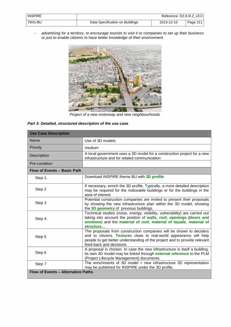
INSPIRE Reference: D2.8.III.2_v3.0
TWG-BU Data Specification on Buildings 2013-12-10 Page 211
- advertising for a territory, to encourage tourists to visit it or companies to set up their business or just to enable citizens to have better knowledge of their environment.
Project of a new motorway and new neighbourhoods
Part 3: Detailed, structured description of the use case
Use Case Description
Name Use of 3D models
Priority medium
Description A local government uses a 3D model for a construction project for a new infrastructure and for related communication
Pre-condition
Flow of Events – Basic Path
Step 1. Download INSPIRE theme BU with 3D profile
Step 2 If necessary, enrich the 3D profile. Typically, a more detailed description may be required for the noticeable buildings or for the buildings in the area of interest
Step 3 Potential construction companies are invited to present their proposals by showing the new infrastructure plan within the 3D model, showing the 3D geometry of previous buildings.
Step 4.
Technical studies (noise, energy, visibility, vulnerability) are carried out taking into account the position of walls, roof, openings (doors and windows) and the material of roof, material of façade, material of structure…
Step 5
The proposals from construction companies will be shown to deciders and to citizens. Textures close to real-world appearance will help people to get better understanding of the project and to provide relevant feed-back and decisions
Step 6 A proposal is chosen. In case the new infrastructure is itself a building, its own 3D model may be linked through external reference to the PLM (Project Lifecycle Management) documents.
Step 7 The enrichments of 3D model + new infrastructure 3D representation may be published for INSPIRE under the 3D profile.
Flow of Events – Alternative Paths

INSPIRE Reference: D2.8.III.2_v3.0
TWG-BU Data Specification on Buildings 2013-12-10 Page 212
Use Case Description
Step 1 bis
Download theme BU with 2D profile. Make 3D representation of buildings by extruding the 2D geometry using height above ground or number of floor above ground or better floor distribution. Typical textures might be guessed from material of roof and material of facade.
Result The new infrastructure has been designed and chosen in a way ensuring a good integration in its environment. The enrichments to the 3D model are available to other users.
B.2 Safety
B.2.1 Travel security
Part 1: UML use case diagram
uc Trav el safety
Travel security
Travellers
NavigatorsAviators
ICAO (International Civil
Aviation Organization)
Civil Aviation Services National
Hydrographic organisations
IHO (International Hydrographic Organisation)
Public Transport Offices
Rescue servicesLocal
governments
Use case diagram for travel security
Part 2: Narrative explanation of the use case Building data is necessary to ensure safe travel both for air navigation (where buildings and other constructions are obstacles and so, as dangers for flights) and for marine navigation (where buildings and other constructions may be used as landmarks and so as helps for navigators). More generally, buildings and constructions having a specific physical aspect constitute landmarks and are useful for any kind of travelling. The requirement for data harmonisation coming from marine and air navigation is quite strong and these two communities have adopted international standards:
- annex 15 of ICAO (International Civil Aviation Organisation) offers a data model for vertical structures (including buildings) called AIXM (Aeronautical Information eXchange Model). - the IHO (International Hydrographic Organisation) has its standard S-57 which comprises the specifications of ENC (Electronic Navigation Charts) and a glossary.
Both include information related to theme Buildings. The case of marine navigation is provided more in detail below but the case of air navigation is quite similar. Hydrographic Organisations have the mission to ensure safety of sea navigation by producing marine charts. These marine charts include navigation aids, bathymetry … They are provided to navigators either

INSPIRE Reference: D2.8.III.2_v3.0
TWG-BU Data Specification on Buildings 2013-12-10 Page 213
through paper charts or through ENC (Electronic Navigation Chart). The specification of Navigation Electronic Chart has been developed by IHO (International Hydrographic Organisation).
Standardised symbols for marine charts Extract of marine chart
Marine charts Part 3: Detailed, structured description of the use case
Use Case Description
Name Updating of Electronic Navigation Charts using INSPIRE building data
Priority high
Description The envisaged scenario is that a Hydrographic Organisation uses INSPIRE data as warnings to update Electronic Navigation Charts (ENC)
Pre-condition Specifications of Electronic Navigation Charts are available.
Flow of Events – Basic Path
Step 1.
Download the evolutions of INSPIRE data (themes BU, US, TN), using queries based on temporal attributes in the data set
- beginLifespanVersion (to get new features) - endLifespanVersion (to get old features)
Step 2
Select the new buildings and other constructions that may be of interest for marine navigation (those easy to be recognized). These queries may be done using attributes constructionNature, buildingNature, heightAboveGround The query will provide features such as chimneys, antennas, stadium, towers, churches, mosques, tanks, silos, windmills, wind turbines
Step 3
Select the new governmental services that may be of interest for marine navigation (e.g. hospital, education) by a query on attribute serviceType. Select the features of interest in theme Transport Network (e.g. raiwayStation).
Step 4 For the selected features, take in the INSPIRE data sets (if available) the information required by ENC specification: 2D geometry, elevation, heightAboveGround, name
Step 5
For the selected features, provide their classification according to ENC specification:
- some values may be taken directly from theme BU (buildingNature and constructionNature)
- some values come from theme US (serviceType) and have to be reported on theme BU (e.g. by using geometry overlay)
- some values may have to redefined with more details (e.g. monument into column, obelisk …).
Step 6 For selected features, add missing information according ordinary update procedures (e.g. computation of a symbol )
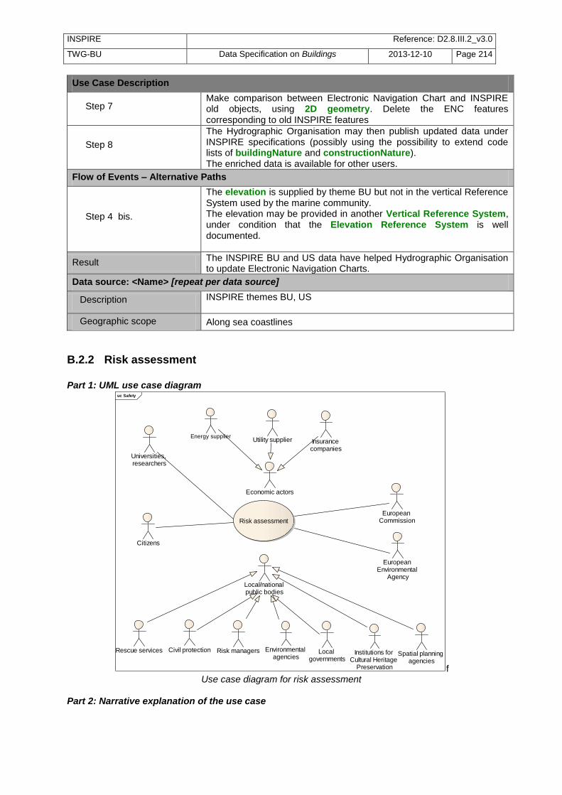
INSPIRE Reference: D2.8.III.2_v3.0
TWG-BU Data Specification on Buildings 2013-12-10 Page 214
Use Case Description
Step 7 Make comparison between Electronic Navigation Chart and INSPIRE old objects, using 2D geometry. Delete the ENC features corresponding to old INSPIRE features
Step 8
The Hydrographic Organisation may then publish updated data under INSPIRE specifications (possibly using the possibility to extend code lists of buildingNature and constructionNature). The enriched data is available for other users.
Flow of Events – Alternative Paths
Step 4 bis.
The elevation is supplied by theme BU but not in the vertical Reference System used by the marine community. The elevation may be provided in another Vertical Reference System, under condition that the Elevation Reference System is well documented.
Result The INSPIRE BU and US data have helped Hydrographic Organisation to update Electronic Navigation Charts.
Data source: <Name> [repeat per data source]
Description INSPIRE themes BU, US
Geographic scope Along sea coastlines
B.2.2 Risk assessment
Part 1: UML use case diagram
uc Safety
Risk assessment
Energy supplier
Risk managersCivil protectionRescue services
European Environmental
Agency
Local governments
Utility supplier Insurance companies
Citizens
European Commission
Universities, researchers
Economic actors
Environmental agencies
Local/national public bodies
Institutions for Cultural Heritage
Preservation
Spatial planning agencies
f Use case diagram for risk assessment
Part 2: Narrative explanation of the use case

INSPIRE Reference: D2.8.III.2_v3.0
TWG-BU Data Specification on Buildings 2013-12-10 Page 215
There are many sources of potential risk and assessment of the risk impact is the first step necessary to take relevant protection and rescue measures.
For instance, the EU Floods Directive (2007/60/EC) Directive requires Member States to assess if all water courses and coast lines are at risk from flooding, to map the flood extent and assets and humans at risk in these areas and to take adequate and coordinated measures to reduce this flood risk.
Earthquake is potentially the most significant hazard as it may cause thousands of death. Some parts of Europe are subject to earthquakes.
Assessment of earthquake risk
In opposite to other continents, Europe is not frequently victim of wind storms. However, this hazard also occurs, as shown by the 1999 wind storm. Moreover, some Member states have over-sea territories which may suffer from frequent wind storms.
Landslides are various types of gravitational mass movements of the Earth‘s surface. ‘‘Landslides’’ are a complex-disaster phenomenon triggered by earthquakes, heavy rainfall
(typhoons, hurricanes), sustained rainfall, volcanic eruptions and heavy snowmelt, unregulated
anthropogenic development, mining, tunnelling and others. Landslides cause many deaths and
injuries and great economic loss to society by destroying buildings, roads, life lines and other infrastructures; they also pose irrecoverable damage to our cultural and natural heritage. Large
and small landslides occur almost every year in nearly all regions of the world. Large-scale coastal or
marine landslides are known to cause tsunami waves that kill many people. Landslides also may occur
just due to progress of natural weathering; therefore, they occur almost everywhere in the world.
Landslides most commonly impact residents living on and around slopes.
The European Forest Fire Information System (EFFIS) has been established by the Joint Research Centre (JRC) and the Directorate General for Environment (DG ENV) of the European Commission (EC) to support the services in charge of the protection of forests against fires in the EU and neighbour countries, and also to provide the EC services and the European Parliament with information on forest fires in Europe. EFFIS addresses forest fires in Europe in a comprehensive way, providing EU level assessments from pre-fire to post-fire phases, thus supporting fire prevention, preparedness, fire fighting and post-fire evaluations.
Although risk assessment it is not always a mandatory task with a legal framework, it is a main component in the disaster management cycle. Moreover, the Solvency Directive aims to ensure that insurance and reinsurance companies have enough funding to be able to reimburse the losses due to hazards. Part 3: Detailed, structured description of the use case

INSPIRE Reference: D2.8.III.2_v3.0
TWG-BU Data Specification on Buildings 2013-12-10 Page 216
Use Case Description
Name Assessment of risk
Priority high
Description The purpose is to estimate the impact of a potential risk
Pre-condition The hazard zone has been delimited. In case of natural hazards, theme NZ is available.
Flow of Events – Basic Path
Step 1. Download INSPIRE theme BU, US, PF, AF TN, … Download theme NZ or use delimitation of human risk (e.g. around a SEVESO site)
Step 2 Based on their 2D geometry, select the features (BU, US, TN, …) located in the hazard area.
Step 3
Assess the general vulnerability of the hazard area. Typically, identify if infrastructures that are essential for the community (such as water / power / telecommunication supply, hospitals, rescue services) are in the hazard area. This may be done using attribute service type of governmental services.
Step 4
In the hazard area, assess the vulnerability of the buildings, e.g. using attributes:
- material of structure for fire or earthquake - number of floors, floor description (with area of openings)
for flood and earthquake - material of façade, material of structure for industrial hazard
According to the results, some buildings may be excluded for a given level of risk. In opposite, some buildings may be identified as more vulnerable than the average, generally based on the height above ground or number of floors (e.g. a low building for flood, a high building for most of other risks) or material of structure (e.g temporary habitat such as mobile homes may be more vulnerable to any risk)
Step 5 In the hazard area, make assessment of the population at night and of the population at day (see common use cases B1.2.1 and B1.2.2)
Step 6
In the hazard area, assess the value of properties. For buildings, this may be done by applying average prices (e.g. by cost/ m
2 in a neighbourhood) using the geometry of building and its
total area (official area or area derived from geometry x number of floors) The value of furniture can not, a priori, be assessed from INSPIRE data.
Flow of Events – Alternative Paths
Step 4 bis. If relevant attributes to assess vulnerability are not available, a rough guess may be done using date of construction and date of renovation. This requires domain expertise.
Step 4 ter
If relevant attributes to assess vulnerability are not available, it may be possible to get them using mechanisms to have access to more detailed information:
- external reference to other information system - document (e.g. building permits, building code, …)
Step 6 bis If available, the official value may be used to refine the assessment of the value of the building property.
Result The risk is assessed and may be reported, if required by a European Directive (e.g. Flood Directive)

INSPIRE Reference: D2.8.III.2_v3.0
TWG-BU Data Specification on Buildings 2013-12-10 Page 217
Use Case Description
Data source: <Name> [repeat per data source]
Description INSPIRE themes BU, US, PF, AF, TN ….
Geographic scope Risk areas in Europe
B.2.3 Risk management
Part 1: UML use case diagram uc Risk management
Risk management
Civil protection
Rescue services Citizens
Ministry of Interior Local/national governments
Use case diagram for risk management
Part 2: Narrative explanation of the use case National and local governments have the responsibility to ensure safety of citizens. They are in charge of risk management, i.e. of the actions to reduce as much as possible the risk and to organise the rescue of people when the hazard occurs.
Buildings in a flooded area
Part 3: Detailed, structured description of the use case
Use Case Description
Name Management of risk
Priority high
Description The purpose is to manage the hazard, in order to decrease its consequences.
Pre-condition The hazard has been (more or less) identified, delimited and assessed

INSPIRE Reference: D2.8.III.2_v3.0
TWG-BU Data Specification on Buildings 2013-12-10 Page 218
Use Case Description
Flow of Events – Basic Path
Step 1. Download INSPIRE theme NZ, BU, US, PF, AF TN, HY, …
Step 2
Check if the environmental barriers (e.g. embankments, dam, …) are adapted to the hazard. If not, improve these environmental barriers or build new ones. Attributes such as height above ground and year of construction will contribute to this checking.
Step 3
Make people aware of the hazard by publishing risk maps (see common use case B1.3). A 3D representation, using 3D geometry, may be more efficient to make people conscious of the risk and so, to make them ready to follow the advices for reducing risk and/or how to act in case of emergency.
Step 4 When possible, based on the assessment of vulnerability, encourage people to decrease the vulnerability of their buildings to hazard (e.g. making buildings stronger to resist avalanches or explosions).
Step 5 a
Schedule in advance the rescue operations, e.g. - based on the results of assessment of population at day and at
night, schedule the number of vehicles necessary in case of evacuation
- schedule the possible itineraries from rescue service to potential hazard areas. Identify key infrastructures, such as bridges and tunnels, check how they may be affected by the hazard, using attributes such as height above ground and year of construction.
Step 5 b
Identify the buildings and governmental services that may be resource in case of hazard, e.g.:
schools, sport infrastructure for emergency shelters (with attribute service type)
open air spaces to gather people
open air pools in case of fire risk
buildings with flat roof for helicopter landing (attribute roof type)
self-sustainable buildings with installations such as wind turbine or solar panels
Step 5 c
Based on the assessment of vulnerability - identify the buildings and governmental services to be rescued
first: e.g. informal settlements and mobile homes (from attribute material of structure) are very vulnerable to flood
- schedule emergency interventions for the buildings with higher risks (e.g. buildings receiving public, very high buildings). Detailed data related to these very risky buildings may be linked to the INSPIRE data using the external reference or the document attribute.
Step 5 d
Rescue services will need to find the building associated to an address; detailed 3D geometry (ideally with description of openings, of internal and external installations such as stairs, lifts and with description of building interior for the largest buildings: rooms and/or building units) will be useful for emergency interventions.
Result The hazard is managed and its consequences are reduced, as much as possible.
Data source: <Name> [repeat per data source]
Description INSPIRE themes NZ, BU, US, PF, AF, TN ….
Geographic scope Everywhere in Europe
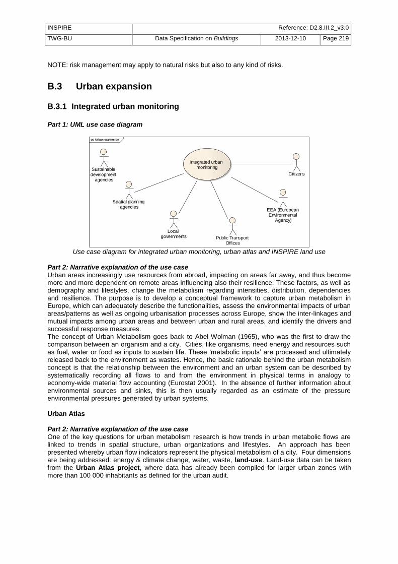
INSPIRE Reference: D2.8.III.2_v3.0
TWG-BU Data Specification on Buildings 2013-12-10 Page 219
NOTE: risk management may apply to natural risks but also to any kind of risks.
B.3 Urban expansion
B.3.1 Integrated urban monitoring
Part 1: UML use case diagram
uc Urban expansion
Integrated urban monitoring
Local governments
Citizens
EEA (European Environmental
Agency)
Spatial planning agencies
Public Transport Offices
Sustainable development
agencies
Use case diagram for integrated urban monitoring, urban atlas and INSPIRE land use
Part 2: Narrative explanation of the use case Urban areas increasingly use resources from abroad, impacting on areas far away, and thus become more and more dependent on remote areas influencing also their resilience. These factors, as well as demography and lifestyles, change the metabolism regarding intensities, distribution, dependencies and resilience. The purpose is to develop a conceptual framework to capture urban metabolism in Europe, which can adequately describe the functionalities, assess the environmental impacts of urban areas/patterns as well as ongoing urbanisation processes across Europe, show the inter-linkages and mutual impacts among urban areas and between urban and rural areas, and identify the drivers and successful response measures. The concept of Urban Metabolism goes back to Abel Wolman (1965), who was the first to draw the comparison between an organism and a city. Cities, like organisms, need energy and resources such as fuel, water or food as inputs to sustain life. These ‗metabolic inputs‘ are processed and ultimately released back to the environment as wastes. Hence, the basic rationale behind the urban metabolism concept is that the relationship between the environment and an urban system can be described by systematically recording all flows to and from the environment in physical terms in analogy to economy-wide material flow accounting (Eurostat 2001). In the absence of further information about environmental sources and sinks, this is then usually regarded as an estimate of the pressure environmental pressures generated by urban systems. Urban Atlas Part 2: Narrative explanation of the use case One of the key questions for urban metabolism research is how trends in urban metabolic flows are linked to trends in spatial structure, urban organizations and lifestyles. An approach has been presented whereby urban flow indicators represent the physical metabolism of a city. Four dimensions are being addressed: energy & climate change, water, waste, land-use. Land-use data can be taken from the Urban Atlas project, where data has already been compiled for larger urban zones with more than 100 000 inhabitants as defined for the urban audit.

INSPIRE Reference: D2.8.III.2_v3.0
TWG-BU Data Specification on Buildings 2013-12-10 Page 220
Urban Atlas Madrid
Part 3: Detailed, structured description of the use case
Use Case Description
Name Extending or updating Urban Atlas
Priority medium
Description This use case applies in the case of an update of Urban Atlas or an extension of Urban Atlas to smaller cities is ordered.
Pre-condition Topographic data (including buildings) and ortho-image are available.
Flow of Events – Basic Path
Step 1. Download INSPIRE topographic themes, mainly OI, BU, US , PF , AF TN and HY
Step 2
This use case is based on the common use case B1.4 Deriving medium scale data in the alternative path of human capture. In this case, buildings are used as auxiliary data for capturing the land use / land cover areas specified by Urban Atlas, main souce being ortho-image.
Step 3
Some buildings may be automatically classified into a land use / land cover area, by following the data capture rules specified by Urban atlas, e.g. :
site of industrial activity, energy plants, water treatment plants, sewage plants, farming industries, antennas, … => industrial, commercial, public, military and private units
schools, universities, hospitals, churches, mosques, temples, chapels, synagogues, penitentiaries, administration buildings, military areas, castles (if not residential) => Public, military and private services not related to the transport system
dams, protectiveStructure, bunkers, city walls, retaining walls (protecting walls) => Civil protection and supply infrastructure
acoustic fence (noise barriers), rest areas => Road and Rail network and associated land
golf courses, amusement parks, sport fields, …=> Sports and leisure facilities
Result A new version or an extended version of Urban atlas is available and may be used to report
Data source: <Name> [repeat per data source]
Description INSPIRE themes BU, US, TN, HY (and possibly OI)
Geographic scope Any urban area in Europe

INSPIRE Reference: D2.8.III.2_v3.0
TWG-BU Data Specification on Buildings 2013-12-10 Page 221
INSPIRE Land Use INSPIRE TWG LU has defined a harmonised classification of land use, applicable by all MS in Europe. At short term, many land use data producers will transform existing land use data sets into the INSPIRE model. At long term, INSPIRE land use map might be carried out directly from other INSPIRE themes, by generalisation. For instance, in urban areas, INSPIRE building data might be used to define some of the possible values of the INSPIRE land use classification.
Principles of INSPIRE land use classification
Part 3: Detailed, structured description of the use case
Use Case Description
Name Producing part of INSPIRE Land Use data
Priority medium
Description This use case applies in the case of a urban planner or local government deriving INSPIRE land use data from topographic data
Pre-condition Topographic data (including buildings) and ortho-image are available.
Flow of Events – Basic Path
Step 1. Download INSPIRE topographic themes, mainly OI, BU, US , PF , AF TN and HY
Step 2 This use case is based on the common use case B1.4 Deriving medium scale data in the alternative path of human capture. The target model is the land use model specified by INSPIRE TWG LU,
Step 3
Buildings having attribute current Use with value industrial may be classified under class B Secondary production: Industrial and manufacturing areas Refinement of LU classification may be done using the attributes from PF
Step 4
Buildings having attribute current Use with value commercesAndServices may be classified under class C Tertiary production: Services Refinement of LU classification may be done using the attribute serviceType from US

INSPIRE Reference: D2.8.III.2_v3.0
TWG-BU Data Specification on Buildings 2013-12-10 Page 222
Use Case Description
Step 5
Buildings having attribute current Use with value residential may be classified under class E Residential areas The sub-classification of residential buildings (individual/collective/for communities), the height or number of floors, the number of dwellings may enable to refine the LU classification: - E1 Single house areas - E2 Medium dense residential area - E3 Dense residential area (blocks of flats) - E4 Residential with compatible activity
Step 6 Buildings and Other Constructions having attribute conditionOfConstruction with value declined or ruins or demolished may be classified under F1 Abandoned areas
Step 7 Buildings and Other Constructions having attribute conditionOfConstruction with value underConstruction may be classified under F3 Transitional areas
Result Part of INSPIRE Land use data is available.
Data source: <Name> [repeat per data source]
Description INSPIRE themes BU, US, TN, HY (and possibly OI)
Geographic scope Any urban area in Europe
Urban metabolism Some of the indicators used to monitor the urban metabolism are related to land use and to buildings
A pragmatic indicator framework for quantifying urban metabolism.
Part 3: Detailed, structured description of the use case
Use Case Description
Name Report indicators related to urban metabolism
Priority high
Description The purpose is to use building data to report indicators related to urban metabolism

INSPIRE Reference: D2.8.III.2_v3.0
TWG-BU Data Specification on Buildings 2013-12-10 Page 223
Use Case Description
Pre-condition The indicators of urban metabolism are adopted.
Flow of Events – Basic Path
Step 1. Download INSPIRE BU, US , SU, PD themes on the area of interest (a priori, city with more than 100 000 inhabitants)
Step 2 Report about building stocks: count the buildings included in the city.
Step 3 Based on the attribute number of dwellings, summarise the number of dwellings included in the city. Report about it.
Step 4 Report about proportion of residents exposed to noise at day, see common use case B1.2.2 (population at day) and the noise use case.
Step 5 Report about proportion of residents exposed to noise at night, see common use case B1.2.1 (population at night) and the noise use case.
Step 6
The report about the proportion of dwellings connected to potable drinking systems may be done, using the external reference to cadastral/official register of buildings where this information may be available in some countries.
Step 7
The report about average area of living accommodation, using:
the total area of buildings devoted to residential purpose (e.g. area derived from 2D geometry x number of floor x percentage of residential current use)
the population of the city
Alternative steps
Step3 bis In case the number of dwellings is not available, a rough estimation may be done using attributes current use (with value residential) and numberOfBuildingUnits
Result The indicators related to urban metabolism that involve building data have been computed and may be supplied to EEA
Data source: <Name> [repeat per data source]
Description INSPIRE themes BU, US, SU, PD
Geographic scope Currently, cities of more than 100 000 inhabitants (where Urban Atlas is available)
NOTE: urban patterns indicators (complexity, centrality, compactness, porosity) will likely be computed from Urban Atlas data (land use / land cover).
B.3.2 Urban planning
Part 1: UML use case diagram
uc Urban planning
Urban planning
Local governments
Citizens
Spatial planning agencies
Public Transport Offices
Sustainable development
agencies
Owners

INSPIRE Reference: D2.8.III.2_v3.0
TWG-BU Data Specification on Buildings 2013-12-10 Page 224
Use case diagram for urban planning Part 2: Narrative explanation of the use case In whole world, including Europe, a powerful force is at work: cities are spreading, minimising the time and distances between and in-and-out of the cities. This expansion is occurring in a scattered way throughout Europe's countryside: its name is urban sprawl. Furthermore, it is now rightly regarded as one of the major common challenges facing urban Europe today. Urban sprawl threatens the very culture of Europe, as it creates environmental, social and economic impacts for both the cities and countryside of Europe. Moreover, it seriously undermines efforts to meet the global challenge of climate change. For instance, coasts are being urbanised at an accelerating rate, and resident communities are being transformed in order to accommodate these new economies. As a result, our coasts are becoming increasingly intertwined with the hinterland and more dependent on tourism and secondary homes. The aim of spatial planning is to control and decide the city expansion by making planned land use maps of the city. These land use maps define the rights and restrictions to construct in an area and draw the city of tomorrow.
Urban fabric evolution data (http://geopensim.ign.fr/)
Planned Land Use Map
Part 3: Detailed, structured description of the use case
Use Case Description
Name Spatial planning
Priority high
Description The purpose is to make maps of planned land use

INSPIRE Reference: D2.8.III.2_v3.0
TWG-BU Data Specification on Buildings 2013-12-10 Page 225
Use Case Description
Pre-condition Necessary data is available. A current land use map is useful. A politic agreement on the spatial planning objectives has been achieved.
Flow of Events – Basic Path
Step 1. Download INSPIRE themes, mainly BU, US , TN , PF, AF and CP
Step 2
In order to understand how the city evolves, it may be useful to represent the city at different dates. The city at a given date T in the past may be reconstituted using the attributes date of construction (by deleting the buildings constructed after T) and date of demolition (by re-integrating the buildings demolished since T)
Step 3
The buildings and facilities / governmental services that generate public easement are identified, e.g.
- protected sites, classified monuments, architectural and urban patrimony - lighthouses - oysters facility - powder shops (Defence-Navy) - military airports - military constructions (forts, …) - tanks (gas, fuel) - cemeteries - stadium (sport installations) - risk installations (e.g. Seveso factories) - radio-electric antennas
Most of them may be found using attributes construction nature, buildingNature, service type. Then, the extend of public easements is defined.
Step 4
Local government decide on a planned use map; the land use areas are generally represented on a background map representing cadastral parcels, existing buildings, transport networks. This planned land use map defines the restrictions of construction for the next years, applying to each parcel.
Step 5.
In order to have a better idea of the consequences of the planned land use map, a 3D model may be done:
- using 3D geometry of existing buildings if available; if not, the volume of buildings may be derived from 2D polygon geometry and height above ground
- for buildings under project or under construction, their 3D geometry may be derived in the same way; the height above ground may have to be searched in the building permit (using attribute document or the external reference mechanism)
- simulated data are used for the new buildings that are allowed by the new spatial planning map.
Result A planned land use map is available and may be published for INSPIRE under LU theme
Data source: <Name> [repeat per data source]
Description INSPIRE themes BU, US, PF, AF, TN, CP
Geographic scope Any urban area in Europe

INSPIRE Reference: D2.8.III.2_v3.0
TWG-BU Data Specification on Buildings 2013-12-10 Page 226
B.3.3 Urban monitoring
Part 1: UML use case diagram
uc Urban monitoring
Urban monitoring
Local governments
CitizensSpatial planning agencies
Owners
Use case diagram for urban monitoring
Part 2: Narrative explanation of the use case The purpose of this use case is to ensure that the rules defined by the spatial planning map and by other regulations are respected.
Detailed cadastral data for urban monitoring
Part 3: Detailed, structured description of the use case
Use Case Description
Name Spatial monitoring
Priority high
Description The purpose is to check if spatial planning decisions (registered in a planned land use map) and other urbanism regulations are respected.
Pre-condition Planned land use map and associated regulations are available. A politic agreement on the spatial planning objectives has been achieved.

INSPIRE Reference: D2.8.III.2_v3.0
TWG-BU Data Specification on Buildings 2013-12-10 Page 227
Use Case Description
Flow of Events – Basic Path
Step 1. Download INSPIRE themes, mainly BU, TN and CP
Step 2 When a owner asks permission for a new building through the building permit, check if the building permit is conform to planned land use map and other regulations
Step 3
When the building construction is achieved, there may be a checking done by field survey to control if the building in real world is conform to building in the building permit. The reference INSPIRE data may be updated to take into account this new building, ideally with all the attributes of the extended profile that are available from the building permit.
Flow of Events – Alternative Paths
Step 3 bis.
Once an area is constructed, the INSPIRE building data may be used to carry out more systematic checks, using the attributes:
- 2D geometry (for deriving its size) - height above ground of the building - material of roof, material of façade - official area (to check if the density indicators were respected) - detailed 2D geometry to measure distance to the road or to
the cadastral boundary.
Step 3 ter
Systematic check may be done at city level, several years after the planned land use map was published (date T), by comparing the buildings effectively constructed (selection of building whose construction date is after T) with the areas where buildings were allowed.
Result The decisions taken for spatial planning are respected.
Data source: <Name> [repeat per data source]
Description INSPIRE themes BU, TN, CP
Geographic scope Any urban area in Europe

INSPIRE Reference: D2.8.III.2_v3.0
TWG-BU Data Specification on Buildings 2013-12-10 Page 228
B.4 Environment
B.4.1 Noise
Part 1: UML use case diagram
uc Noise assessment
Noise assessment
Local governments
European Environment Agency (EEA)
Universities, research
Owners
Sustainable development
agencies
Spatial planning agencies
Citizens
National/local enviromnental
agencies
Institute for health monitoring
National/local public bodies
Use case diagram for noise assessment
NOTE: this use case diagram applies to B4.1, B4.2 and B4.3.
Part 2: Narrative explanation of the use case European legislation (Environmental Noise Directive; END) defines obligations to consider the environmental noise and noise sources and appropriate actions to address and manage noise issues within the Member States (MS). The scope of the END Directive (Art.2) defines, that this Directive shall apply to environmental noise to which humans are exposed in particular in built-up areas, in public parks or other quiet areas in an agglomeration, in quiet areas in open country, near schools, hospitals and other noise-sensitive buildings and areas. MS establish competent authorities and bodies for making or approving and collecting noise maps and action plans for agglomerations, major roads, major railways and major airports. These authorities are usually designated at local level and hierarchical level of authorities is usually used to collect data (example: from local level) and report to the EC (example: from national level). MS have to report to the European Commission certain data related to strategic noise maps, action plans, noise control programmes, computation or measurement methods used to provide noise values, estimation of people exposed to noise values, etc.

INSPIRE Reference: D2.8.III.2_v3.0
TWG-BU Data Specification on Buildings 2013-12-10 Page 229
Extract of a noise map around an airport
Part 3: Detailed, structured description of the use case
Use Case Description
Name Assessment and reporting for Noise Directive
Priority high
Description The purpose is to assess and report noise indicators, in conformance with Noise Directive.
Pre-condition Data related to noise source (e.g. air traffic, road traffic) is available
Flow of Events – Basic Path
Step 1. Download INSPIRE themes, mainly BU, US and TN
Step 2
The noise extend is delimited as explained in common use case B1.1 (Modelling of physical phenomena). Main attributes to be considered are the geometry, the height above ground (that may influence the height at which the noise has to be estimated), the roof type (ideally as 3D geometry), the material or texture of façade (that may enable domain experts to deduce noise insulation).
Step 3
The estimation of dwellings, schools, hospitals exposed to noise is done by selecting the buildings and governmental services located in the noise extend:
- spatial query based on their 2D geometry - semantic query based on service type (for schools, hospitals) - semantic query based on number of dwellings for buildings
Step 3 The estimation of people exposed to noise is done as explained in common use cases B1.2.1 (population at night) and B1.2.2 (population at day)
Step 4
Number of people in dwellings with special insulation + ventilation / air conditioning may be assessed by searching detailed information about insulation, ventilation in official building register or in building permits (using document or external reference attributes) and/or by attribute installation nature (e.g. airDuct, air conditioning unit).
Step 5 (optional)
The assessment is done with more details, the floors reached by excessive noise are identified (through the height in floor description). Owners of building units in these floors may receive subsidies to improve insulation.
Result Noise indicators are reported (partly) in conformance to Noise Directive.

INSPIRE Reference: D2.8.III.2_v3.0
TWG-BU Data Specification on Buildings 2013-12-10 Page 230
Use Case Description
Data source: <Name> [repeat per data source]
Description INSPIRE themes BU, US, CP
Geographic scope Areas around airports and main roads.
Note: it is unsure that INSPIRE BU data will be enough to assess the number of people in dwellings with quiet façade
B.4.2 Air quality
Part 2: Narrative explanation of the use case The European legislation (new Directive 2008/50/EC of the European Parliament and of the Council of 21 May 2008 on ambient air quality and cleaner air for Europe, Council Directive 96/62/EC - Air Quality Framework Directive) require to make yearly reporting (around July – August) about the areas where air
quality is bad (proportion of pollutants higher than the authorized ones) and the populations concerned by this bad air quality Assessment of air quality may also be useful for urban expansion (e.g. to avoid building a school in a polluted area) or to organise public transport (to reduce the pollution due to car traffic). Data related to buildings are used for two purposes:
- as input parameters in the model to compute propagation of traffic pollution; repartition of buildings has an impact how the pollutants are disseminated (open streets) or not (canyon streets)
- as basis to estimate the number of people in each air quality area.
Air quality mapping – Air quality propagation
Part 3: Detailed, structured description of the use case The air quality use case step by step description is very similar to the noise use case one. See B4.1
B.4.3 Soil
Part 2: Narrative explanation of the use case Soil is essentially a non-renewable resource and a very dynamic system which performs many functions and delivers services vital to human activities and ecosystems survival. Information available suggests that, over recent decades, there has been a significant increase of soil degradation processes, and there is evidence that they will further increase if no action is taken. The European Commission has prepared a project of Soil Directive. Among other measures, the proposed Directive includes:
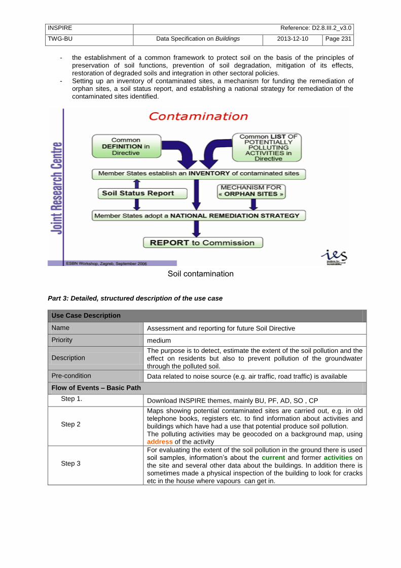
INSPIRE Reference: D2.8.III.2_v3.0
TWG-BU Data Specification on Buildings 2013-12-10 Page 231
- the establishment of a common framework to protect soil on the basis of the principles of preservation of soil functions, prevention of soil degradation, mitigation of its effects, restoration of degraded soils and integration in other sectoral policies.
- Setting up an inventory of contaminated sites, a mechanism for funding the remediation of orphan sites, a soil status report, and establishing a national strategy for remediation of the contaminated sites identified.
Soil contamination
Part 3: Detailed, structured description of the use case
Use Case Description
Name Assessment and reporting for future Soil Directive
Priority medium
Description The purpose is to detect, estimate the extent of the soil pollution and the effect on residents but also to prevent pollution of the groundwater through the polluted soil.
Pre-condition Data related to noise source (e.g. air traffic, road traffic) is available
Flow of Events – Basic Path
Step 1. Download INSPIRE themes, mainly BU, PF, AD, SO , CP
Step 2
Maps showing potential contaminated sites are carried out, e.g. in old telephone books, registers etc. to find information about activities and buildings which have had a use that potential produce soil pollution. The polluting activities may be geocoded on a background map, using address of the activity
Step 3
For evaluating the extent of the soil pollution in the ground there is used soil samples, information‘s about the current and former activities on the site and several other data about the buildings. In addition there is sometimes made a physical inspection of the building to look for cracks etc in the house where vapours can get in.

INSPIRE Reference: D2.8.III.2_v3.0
TWG-BU Data Specification on Buildings 2013-12-10 Page 232
Use Case Description
Step 4
Analysis of the possible remediation is done, using following attributes: current use, date of construction, number of floor, roof and wall material, value (in some cases if low valued the building can be demolish to clean the soil more effectively). Height above ground is relevant according to degassing and wind condition. The area may be derived from the 2D geometry of the building or official area may be used. The owner of the building may be found in official register of buildings using the external reference of the Building or BuildingUnit or the association or spatial overlay with cadastral parcels. Information about stairs and chimneys is useful vapours from pollution can be spread through these channels. It may be searched using attribute Document (e.g. sketches of building or building permit) Retired features are necessary to explore which buildings that have been on the site, and what kind of function they had.
Result Inventory of contaminated soils and report about remediation actions is ready to be reported for the future Soil directive
Data source: <Name> [repeat per data source]
Description INSPIRE themes BU, PF, SO, CP, AD
Geographic scope Everywhere in Europe
B.4.4 Energy / Sustainable buildings
Part 1: UML use case diagram uc Env ironment
Energy consumption assessment - promotion of
sustainable buildings
National/local enviromnental
agencies
European Environment
Agency (EEA)
CitizensOwners
Energy suppliers
Eurostat
Local governments
National statistical institutes
Agencies for sustainable development
Use case diagram for energy / sustainable buildings JRC has launched a working Group whose aim is to prepare cross-sectoral policies, standards and regulations related to the construction sector in order to promote the sustainability of buildings during their whole life-cycle. The development of a multi-performance labelling of buildings in terms of safety, health, energy efficiency and sustainability is one of the long-term objectives of this Working Group.

INSPIRE Reference: D2.8.III.2_v3.0
TWG-BU Data Specification on Buildings 2013-12-10 Page 233
Proposed multi-performance labelling of buildings in terms of safety, health, energy efficiency and
sustainability (―Building Efficiency Index‖). However, currently, only the assessment of energy performance is required by an environmental Directive, the Energy Performance of Building Directive. Applying the Energy Performance of Building Directive Part 2: Narrative explanation of the use case Energy consumption produces emissions of CO2 and so contributes to the greenhouse effect and to the increase of temperatures. Over a decade ago, most countries joined an international treaty -- the United Nations Framework Convention on Climate Change (UNFCCC) -- to begin to consider what can be done to reduce global warming and to cope with whatever temperature increases are inevitable. More recently, a number of nations approved an addition to the treaty: the Kyoto Protocol, which has more powerful (and legally binding) measures. At European level, the Energy Performance of Buildings Directive, (EPBD) requires unique building identification for the buildings certificates. Part 3: Detailed, structured description of the use case
Use Case Description
Name Implementing the Energy Performance of Building Directive
Priority high
Description The purpose is to implement the Energy Performance of Building Directive. The Energy Performance of buildings has to be calculated only for new buildings or when a building is rent or sold.
Pre-condition Building data is available
Flow of Events – Basic Path
Step 1. Download INSPIRE theme BU, US.
Step 2
Identify the buildings that are under the scope of the Energy Performance of Building Directive, using attributes:
- 2D geometry or official area to get the size of the building (< 50 m
2 : no requirement, > 1000 m
2 : higher requirements)
- classification of the building (i.e. current use and service type) for possible exclusions (religious buildings, agricultural buildings, industrial sites, workshops)
Step 3
Prepare the evaluation methodology. The calculation method should take into account thermal insulation, heating and air-conditioning installations, application of renewable energy sources, design of the building and temporal aspects (distinction between existing and new buildings, age of building). Number of floors has also influence. This kind of information may be more or less found in INSPIRE data, using for instance date of construction, external reference to official building register or to building permit. It has generally to be completed by field survey.

INSPIRE Reference: D2.8.III.2_v3.0
TWG-BU Data Specification on Buildings 2013-12-10 Page 234
Use Case Description
Step 4
The evaluation of energy performance of building is performed when a building is sold or rent. The owner or the tenant of the building may be found in official register
of buildings using the external reference of the Building or Building Unit or the association or spatial overlay with cadastral parcels.
Step 5 The result of this evaluation may be captured to updated INSPIRE data, under attribute energyPerformance
Result The Energy Performance of Building Directive has been applied; information about energy performance is available for environmental studies.
Data source: <Name> [repeat per data source]
Description INSPIRE themes BU, PF, SO, CP, AD
Geographic scope Everywhere in Europe
Promoting reduction of CO2 emissions Part 2: Narrative explanation of the use case Moreover, some Member States or local governments are willing to have more pro-active policy and to encourage citizens to improve heating efficiency of their buildings (by better isolation). Better insulation not only reduces the emissions of greenhouse gazes but also contributes in long-term to money saving for inhabitants and to reduce the energy dependency of European countries.
Infra-red images showing loss of energy by roof or by façade. Part 3: Detailed, structured description of the use case
Use Case Description
Name Promoting the reduction of CO2 emissions by buildings
Priority high
Description The purpose is to assess the energy demand of buildings and/or to detect the houses with heat losses and to encourage owners to make insulation works.
Pre-condition Data related to buildings is available. Domain expertise is required.
Flow of Events – Basic Path
Step 1. Download INSPIRE theme BU

INSPIRE Reference: D2.8.III.2_v3.0
TWG-BU Data Specification on Buildings 2013-12-10 Page 235
Use Case Description
Step 2
Assess the energy demand of buildings. Ideally, this should be done using LoD4 representation of buildings with geometric description of building units and detailed information with attributes material of roof, material of façade, heating source, heating system (or by searching information about heating in cadastral register by the external reference) and with feature type installations (air conditioning unit, solar panel, wind turbine). The assessment may be done in a rough way, by using 2D geometry, height above ground or number of floors and by deriving the above information about quality of construction and heating from year of construction and year of renovation
Step 2
Identify the buildings with significant heat losses. This may be done using different methodologies: Deriving it from the assessment of energy demand (step2 using infra-red images to show heat losses by roof (aerial images) or by façade (images taken from a vehicle in the street)
Step 3
Prepare representations of the results. This may generally be done using the common use case B1.3 (Large scale mapping). Note that to represent the results of infra-red roof images, the 2D geometry (polygon) of buildings is required, preferably captured by roof edge. To represent the results façade of infra-red images, the 3D geometry of buildings is required.
Step 5
To make inhabitants aware of the results, the resulting map or 3D model may be published on a Web site or an extract may be sent to the owner. The owner of the building may be found in official register of buildings using the external reference of the Building or BuildingUnit or the association or spatial overlay with cadastral parcels.
Step 5 Local or national governments may envisage financial incitation (e.g. tax
reduction) to promote insulation. The cost of this measure may be estimated, based on the previous results
Step 6
Local or national governments are also building owners. In order to show exemplarity, they may be willing to make insulation works in their own patrimony. Analysis of more detailed data (such as 3D geometry with shape of
roofs and openings, images of buildings under document attribute) will help them to make first identification of the insulation works to be done.
Result Building owners are aware of the heat losses and so, may be encouraged to reduce them by insulation works.
Data source: <Name> [repeat per data source]
Description INSPIRE themes BU
Geographic scope Everywhere in Europe
Sun exposure Part 2: Narrative explanation of the use case The aim is to detect buildings on which solar panels may be installed, in order to promote use of renewable energies and to ensure better sustainability of the building. The expected result is maps showing these buildings with good sun exposure. An indicator about sun exposure (number of sunny hours by day) has to be computed. Part 3: Detailed, structured description of the use case
Use Case Description
Name Sun exposure

INSPIRE Reference: D2.8.III.2_v3.0
TWG-BU Data Specification on Buildings 2013-12-10 Page 236
Use Case Description
Priority high
Description The purpose is to identify the buildings that are relevant for installation of solar panels on their roof.
Pre-condition Building and elevation data available.
Flow of Events – Basic Path
Step 1. Download INSPIRE theme BU, EL, possibly OI
Step 2
Compute the propagation of sun. This may be done as explained under common use case B1.1 modelling of physical phenomena. Ideally, should be done with 3D geometry with shape of roof. However, rough assessment may be done using 2D geometry and height above ground. This computation gives the buildings with good sun exposure.
Step 3
Refine the analysis to identify the roofs that may receive solar panels: - Using the attribute material of roof and/or roof shape,
exclude the buildings that are not appropriate (e.g. covered by thatch)
- Owners are generally reluctant to set solar panels if the building has a roof terrace. An investigation may be done using images of roof (as document) or high-resolution ortho-image
Step 4
An electricity company may want to prospect building owners to propose them installation of solar panel. This may be done by field prospecting. A working map has to be prepared to hep the prospector to find the relevant buildings, as described in common use case B1.3 Large scale mapping.
Result The buildings that may receive solar panels are known.
Data source: <Name> [repeat per data source]
Description INSPIRE themes BU, EL, possibly OI
Geographic scope Sunny areas in Europe
B.4.5 Quality of habitat
Part 1: UML use case diagram
uc Quality of habitat
Quality of habitat
National/local enviromnental
agencies
European Environment
Agency (EEA)
Citizens
Local governments
Agencies for spatial planning
Health monitoring institutes
Use case diagram for quality of habitat
Part 2: Narrative explanation of the use case The general purpose is to carry out studies about habitat (e.g. social habitat, unhealthy habitat, urbanism documents) and to make deciders (municipality level) aware of the evolution of their territory.
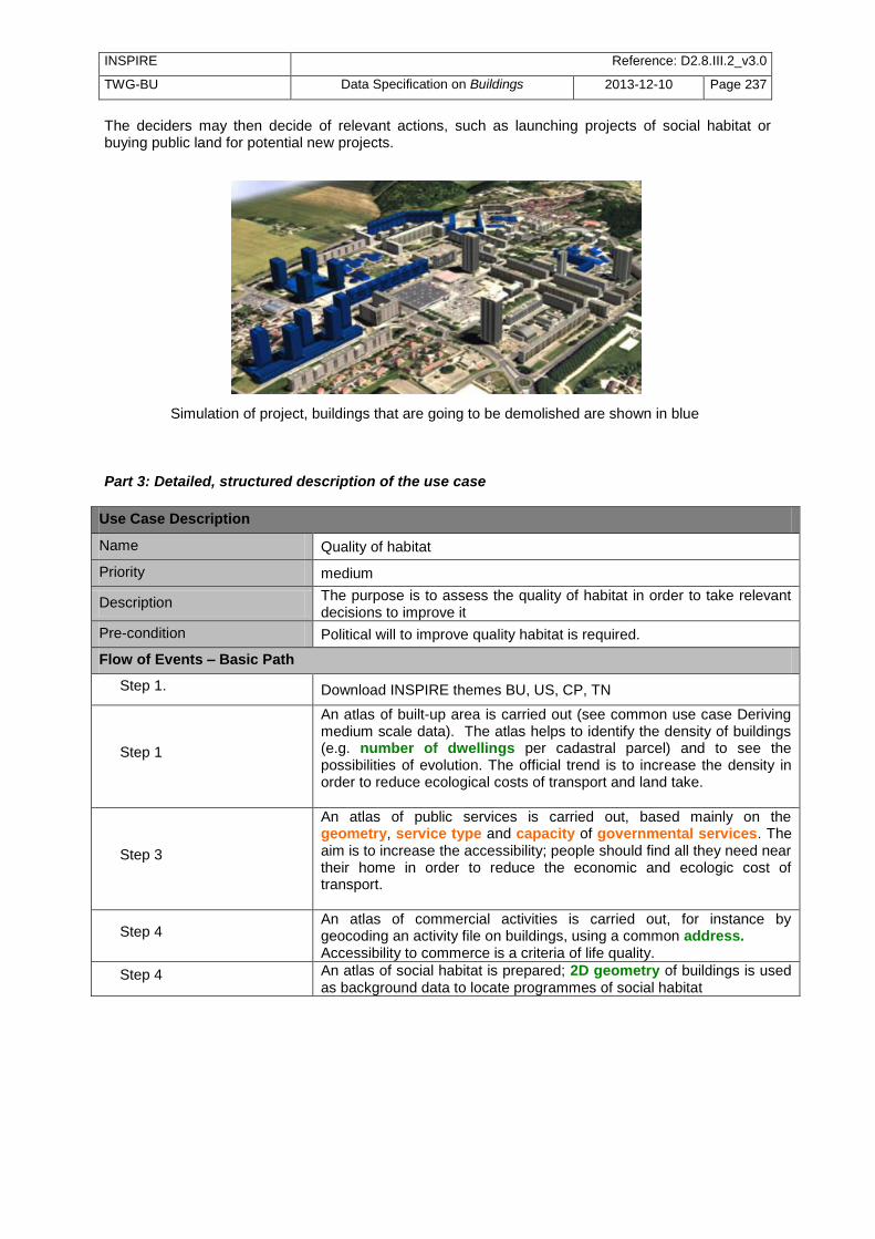
INSPIRE Reference: D2.8.III.2_v3.0
TWG-BU Data Specification on Buildings 2013-12-10 Page 237
The deciders may then decide of relevant actions, such as launching projects of social habitat or buying public land for potential new projects.
Simulation of project, buildings that are going to be demolished are shown in blue Part 3: Detailed, structured description of the use case
Use Case Description
Name Quality of habitat
Priority medium
Description The purpose is to assess the quality of habitat in order to take relevant decisions to improve it
Pre-condition Political will to improve quality habitat is required.
Flow of Events – Basic Path
Step 1. Download INSPIRE themes BU, US, CP, TN
Step 1
An atlas of built-up area is carried out (see common use case Deriving medium scale data). The atlas helps to identify the density of buildings (e.g. number of dwellings per cadastral parcel) and to see the possibilities of evolution. The official trend is to increase the density in order to reduce ecological costs of transport and land take.
Step 3
An atlas of public services is carried out, based mainly on the geometry, service type and capacity of governmental services. The aim is to increase the accessibility; people should find all they need near their home in order to reduce the economic and ecologic cost of transport.
Step 4 An atlas of commercial activities is carried out, for instance by geocoding an activity file on buildings, using a common address. Accessibility to commerce is a criteria of life quality.
Step 4 An atlas of social habitat is prepared; 2D geometry of buildings is used as background data to locate programmes of social habitat

INSPIRE Reference: D2.8.III.2_v3.0
TWG-BU Data Specification on Buildings 2013-12-10 Page 238
Use Case Description
Step 5
Monitoring of co-ownership properties is done. If a property has significant vacant flats, quick turn-over of owners and big rate of rent, it means that this habitat programme was not successful. This information may be found in the official building register by the external reference. The local government should not reiterate this type of building programme and may also take measures such as subsidies for work in buildings, buying unused dwellings and/or common parts … in order to improve the situation of the unsuccessful co-ownership property.
Step 6
An atlas of precarious/bad condition habitat is carried out. Information about precarious buildings (mobile homes, caravan sites, shelters, ..) is useful. These kind of habitat may also be assessed by using both data about income of population and data related to the building (date of construction, date of renovation, number of dwellings, 2D geometry + number of floors + current use to derive the habitable area). For instance, the number of occupants by dwelling is a good indicator. Presence of comfort elements (toilet, heating, kitchen, water supply) may be found in official cadastral register, using the external reference.
Step 7
An analysis of healthy/unhealthy habitat is conducted, e.g. influence of heat waves, noise, air pollution, radon, risk of lead poisoning. Attributes date of construction, material of roof / façade /structure, heightBelowGround or numberOfFloorsBelowGround (for radon), 3D geometry with openings (for noise and heat propagation) are necessary to conduct this type of analysis.
Step 8
Some buildings are considered as totally inappropriate for habitat; local government decides to demolish them in order to construct more adapted dwellings and/or services. The 3D geometry of building is used for 3D models that enable deciders and citizens to realize the impact of the project.
Result Local governments have a clear idea about the quality of habitat and may take relevant decisions.
Data source: <Name> [repeat per data source]
Description INSPIRE themes BU, US, TN, CP
Geographic scope Everywhere in Europe
B.4.6 Buildings with historical or architectural interest
Part 1: UML use case diagram
uc Env ironment
Buildings with historical or architectural interest
Local governments
Tourists
Universities, researchers
Citizens
Institutions for Cultural
Preservation Heritage
Tourim offices
Use case diagram for buildings with historical or architectural interest

INSPIRE Reference: D2.8.III.2_v3.0
TWG-BU Data Specification on Buildings 2013-12-10 Page 239
Part 2: Narrative explanation of the use case Europe countries have had a long history and beneficiate of a rich architectural patrimony. The aim of this use case is to share and increase the knowledge about buildings with historical and architectural interest and to make valorisation of this patrimony through communication actions.
Mont Saint-Michel (France)
Part 3: Detailed, structured description of the use case
Use Case Description
Name Buildings with architectural or historical interest.
Priority medium
Description The purpose is to share and increase the knowledge about buildings with historical and architectural interest and to make valorisation of this patrimony.
Pre-condition Building data is available
Flow of Events – Basic Path
Step 1. Download INSPIRE theme BU, US, TN, CP, PF
Step 2 - Scenario 1
Decision to collect the work of various researchers in history and archaeology is taken. Moreover, the results of these researches will be located, using INSPIRE data as background. 2D geometry of buildings is used to locate the historical/architectural buildings
In case of buildings that still exist, the INSPIRE 2D geometry may be used as it is
In case of buildings that no longer exist, their geometry may be located using relative distance to current BU, TN, …. It may be represented by a polygon or roughly by a point
Step 2 - Scenario 2
A more ambitious decision is taken: to make inventory of all buildings with historic or architectural interest. INSPIRE data may be used to prepare the field survey by identifying the
areas to be investigated (for instance, it is unlikely that a new suburb area with cheap houses looking like one another deserves to be visited). This first selection may be done using attributes such as year of
construction, condition of construction (ruins), official value, construction nature (monument), building nature (church, chapel, castle), service type (hospital, governmental service, university, …). INSPIRE data is used to make work maps for the field survey, as
described in the common use case B1.3 large scale mapping.

INSPIRE Reference: D2.8.III.2_v3.0
TWG-BU Data Specification on Buildings 2013-12-10 Page 240
Use Case Description
Step 3
The work of researchers or the results of the inventory is structured according to the INSPIRE application schema, using mainly the temporal attributes (condition of construction, date of construction, date of renovation, date of demolition), the possibility to attach documents to a building. The classification of buildings may be done by extending attributes construction nature and building nature or by adding other attributes. The result of this work may be published on a Web site and contributes to enrich the knowledge of the city history.
Step 4
Once the patrimony has been identified, other actions may be conducted to make valorisation of the territory. For instance:
- Maps of the city at different dates may be produced. - The results may be shown on current cadastral plan (interest for
the owners of the parcel) - Walking tours may be organised - Protection measures of the patrimony may be taken
It may also be a motivation for ordering the production of the detailed 3D geometry of these buildings, in order to enrich the web site or brochures of the city.
Result The knowledge about buildings with architectural or historical interest has increased and may be shared by everyone
Data source: <Name> [repeat per data source]
Description INSPIRE themes BU, US, PF, TN, CP
Geographic scope Everywhere in Europe
B.5 Infrastructures Part 1: UML use case diagram
uc Infrastructure
Infrastructure implementation and
management
Local governments
Construction companies
Public Transport Offices
Utility manager
Citizens
Sustainable development
agencies
Spatial planning agencies
Use case diagram for Infrastructure implementation and management
B.5.1 Location of a new service/activity
Part 2: Narrative explanation of the use case

INSPIRE Reference: D2.8.III.2_v3.0
TWG-BU Data Specification on Buildings 2013-12-10 Page 241
Example 1: find better location for new antennas The purpose is to find, for potential new antennas, the buildings reached by this antenna and then, to estimate the percentage of buildings covered /reached by this antenna. Several potential locations for the antenna have been identified. For each of this position, a simulation is done, by making ―visibility maps‖ from the antennas (see common use case B1.1 modelling of physical phenomena). The location that is ―visible‖ by the higher percentage of buildings will be considered as the best one. Example 2: prove the necessity of a new antenna. A telecommunication company is initiating a project related to implementation of new antennas for mobile phone. The influence area of an antenna depends of the landscape, for two reasons:
- buildings may disturb propagation of phone waves - more antennas are needed in urban areas to be able to deal with more calls
For instance, in rural areas, the antenna impact varies from 2 km to 35 km. In urban areas, the antenna impact may be smaller than 500 m. As there are doubts about influence of phone antennas on health, the telecommunication company has to give rationale for implementation of a new antenna and must prove that there are requirements to get permission from local governments. So, the telecommunication company need to determine the characteristics of the area around the new antenna. For instance, the need for mobile phone is bigger in large business areas than in residential areas. The density of buildings is also a significant criteria. There is socio-economic data on statistical units but building data is required for more accurate spatial location of this information (see common use case B1.2.2 Computation of population at day). Example 3: Location of new bus stops There is obvious need for organizing and scheduling of public transport. A main goal of the application is to create / change / delete bus stops and bus stations and to connect the different stops and stations so that they reach a maximum number of people (in city centres, near points of interest …) in the shortest possible time. Another purpose is to provide up-to-date information about the routes and stops to all the employees and citizens. Several scenarios are envisaged for the location of a new bus stop; the area served by the bus stop is delimited (e.g. less than 300 m or less than 5 or 10 minutes walking). Then, the application computes the population that may beneficiate of this new bus stop (see common use case B1.2 about computation of population at day and at night). Example 4 : Location of new highway (or high speed train) Location of new highway is a complex process in which several steps are required. The purpose is double:
- serve transport needs as much as possible - disturb local population as few as possible
The first step is to define the rough areas where the highway should be located.
Rough area(s) where the highway Number of buildings and inhabitants 1 km around the highway

INSPIRE Reference: D2.8.III.2_v3.0
TWG-BU Data Specification on Buildings 2013-12-10 Page 242
should be located
Studies to find better location of a new highway
Then, there is then a need to assess the impact of the project (to identify which buildings are concerned by the project). Visibility / intervisibility maps may be created for this project, e.g. to ensure that a nice site is visible from the highway / the train or to identify the least visible areas along the transport network). Noise maps may be simulated to show the impact of the new highway or railway.
Current status With anti-noise wall With tunnel
Simulation of anti-noise infrastructure impact
3D representation to make 3D model simulating the new project are useful to communicate with the inhabitants impacted by the project. Example 5: Location of a new wind farm An electricity company is looking for new sites to set up wind turbines. In first phase, geographic data is required to identify potential sites. Then, the study is completed by field survey. Data related to buildings are required because wind turbines must be far enough from buildings
Use Case Description
Name Location of a new wind farm
Priority high
Description The purpose is to identify the potential location of new wind farms.
Pre-condition
Flow of Events – Basic Path
Step 1. Download INSPIRE theme AC, MF, BU, EL, TN, PS, CP
Step 2 Compute the areas that receive enough wind (see common use case B1.1 modelling of physical phenomena)
Step 3
A wind farm must be at least at 500 m from a residential building. Using attribute current use, select residential buildings. Create an exclusion zone by making a buffer of 500 m around the 2D geometry of these buildings.

INSPIRE Reference: D2.8.III.2_v3.0
TWG-BU Data Specification on Buildings 2013-12-10 Page 243
Use Case Description
Step 4
Using attributes construction nature and specific interest, select the specific buildings or constructions that generate easements for wind turbines (castles, churches, radars, television towers, antennas, pylons, transformers, airports, SEVESO sites). More generally, the buildings that have an interest for landscape generate more constraints than ordinary buildings. These buildings are those having historical or architectural interest, some are under official classification / protection but not all (for instance, traditional, well-preserved village
Step 5
Make visibility maps around the specific buildings that generate more constraints; for these specific buildings, a detailed 3D geometry with location of openings enables more detailed results. The areas where the wind farm is visible from these specific buildings must be excluded.
Step 6
The area where it is possible to locate a new wind farm is now known. But it is necessary to get owner agreement. The cadastral parcels located in the favourable area are selected and the owner is found using the national cadastral reference and the negotiation may begin….
Result The location for a new wind farm is found.
Data source: <Name> [repeat per data source]
Description INSPIRE themes AC, MF, BU, EL, TN, PS, CP
Geographic scope Windy areas in Europe
Example 4 : High voltage power line An electricity company need to set up a new high voltage power line crossing an inhabited area.
Use Case Description
Name Location of a new high voltage power line
Priority high
Description The purpose is to check that the new line will not be in conflict with existing buildings.
Pre-condition The potential location of the power line has been defined
Flow of Events – Basic Path
Step 1. Download INSPIRE theme BU
Step 2
The power line is above ground. Using the attributes 2D geometry + height (or elevation preferably captured at highest point) or the 3D geometry of buildings and other constructions, check if the scheduled location of power line is fine, i.e. if it respects the minimum distances
Step 3
The power line is underground. Using the attributes 2D geometry (preferably captured as envelope) and height below ground or number of floors below ground, check if the scheduled location of power line is fine, i.e. if it respects the minimum distances
Result The location for the new high voltage power line has been checked.
Data source: <Name> [repeat per data source]
Description INSPIRE themes BU
Geographic scope Anywhere in Europe

INSPIRE Reference: D2.8.III.2_v3.0
TWG-BU Data Specification on Buildings 2013-12-10 Page 244
B.5.2 Management of service/activity
Part 2: Narrative explanation of the use case Example 1: computing population reached by television channels The national government wants to assess the percentage of population that receive television channels.
Use Case Description
Name Computation of population reached by television channels
Priority medium
Description The purpose is to compute population reached by television channels, using a grid for population
Pre-condition There is a software taking the population grid as input to check which population was reached or not by television channels.
Flow of Events – Basic Path
Step 1. Download INSPIRE theme BU, SU, PD
Step 2
Attribute a number of inhabitants for each building (see first steps of common use case B1.2.1 Computation of population at night), using attributes 2D geometry, number of floors and current use (residential).
Step 3
Select for each building the nearest node of the grid (regular grid of 100m). The result of the query may be stored using the inspireID. If available, use 2D geometry as point to make computation quicker. If not available, the point geometry may be derived from the polygon geometry.
Step 4 Give to each node of the grid the population of the buildings related to this grid node.
Result The population data is available in the way suitable for the software.
Data source: <Name> [repeat per data source]
Description INSPIRE themes BU, SU, PD
Geographic scope Anywhere in Europe
NOTE 1: This example shows the interest of multiple representations of buildings as polygons and as points. NOTE 2: In a current statistical project of Eurostat, the population has to be related to the cells of a km² grid. The methodology for doing so (transfer of statistical data from existing statistical units to a new kind of statistical units) might be quite similar. Example 2: managing refuse collection A public body has to organise the refuse collection in a city. A building in this context will either be a dwelling or premise that requires local authority service delivery in the form of waste collection services.
Use Case Description
Name Management of refuse collection
Priority medium

INSPIRE Reference: D2.8.III.2_v3.0
TWG-BU Data Specification on Buildings 2013-12-10 Page 245
Use Case Description
Description The purpose is to manage in an efficient way the refuse collection in a city.
Pre-condition
Flow of Events – Basic Path
Step 1. Download INSPIRE theme BU, US, PF, TN, AD, ..
Step 2 Using attribute condition of construction, the functional buildings (those deserving refuse collection) are selected.
Step 3 The volume of expected refuse is assessed according to the current use of the building and to its size (official area or area derived from 2D geometry x number of floors)
Step 4
Itineraries for refuse collection are prepared, based on the results of previous assessments. The 2D geometry of buildings may be used to prepare working maps (see common use case B1.3 Large scale mapping)
Step 5
When the owner / occupier of the building contact the local authority via the call centre, it is necessary to be able to find the concerned building. This may be done by using the external reference to link geographic data to the information system of owners/occupants
Step 6
Temporal studies are carried out in order to prepare evolutions of the refuse collection, e.g.
- study of the past by reconstituting the city with attributes date of construction, date of demolition
- study in next future by taking into account buildings whose condition of construction is under project or under construction
Result The refuse collection is managed in an efficient way..
Data source: <Name> [repeat per data source]
Description INSPIRE themes BU, US, PF, TN, AD, ..
Geographic scope Anywhere in Europe
Example 3 : Landing of stratospheric balloons French Spatial Agency (CNES) is in charge of launching stratospheric balloons over France and other countries. These stratospheric balloons are not inhabited; they are guided either from CNES in Toulouse or from the launch site. They carry scientific material for studying atmospheric conditions (e.g. winds) or composition. There are lots of demands for example in the context of climate change and of decrease of ozone layer. These studies enable better understanding of current status of atmosphere and some anticipation. Landing of balloons may be dangerous for the people living in the landing area. There are thresholds which should not be exceeded. The risk depends on the characteristics (mainly weight) of balloon and of landing area. For instance, for the heaviest (and so the most dangerous balloons), the risk factor should not exceed 1 or 2 persons/km
2. The landing area may be up to several km
2.
Building data are used to compute this risk factor (see common use case Computation of population at night) and to so to check if the scheduled landing area conforms to the regulation.

INSPIRE Reference: D2.8.III.2_v3.0
TWG-BU Data Specification on Buildings 2013-12-10 Page 246
B.5.3 Management / valorisation of public patrimony
Part 1: UML use case diagram
uc Infrastructure
Management / valorisation of public
patrimony
Citizens
National/local governments
Ministry of Budget
Private owners
Institutions for Cultural Heritage
Preservation
Public owners
Use case diagram for management: valorisation of public patrimony
Part 2: Narrative explanation of the use case National and local governments as well as other public bodies are generally owners of a significant part of land and of buildings. They obviously need building data for their infrastructure projects but also for daily management. Part 3: Detailed, structured description of the use case
Use Case Description
Name Managing Public Property
Priority medium
Description The purpose is to manage public property.
Pre-condition Building data is available
Flow of Events – Basic Path
Step 1. Download INSPIRE theme BU, US, CP
Step 2
Decision is taken to constitute a land reserve. The owners who let their buildings abandoned may be good willing to sell their property. Based on attribute condition of construction, select the buildings and construction that are declined or ruins. Based on the national cadastral reference of parcels and/or the external reference of buildings or building units, identify the owner in the cadastral register. The official value may be used to estimate the price the local/national government will propose.
Step 3 A dispute occurs with neighbours of a public building, for instance about adjoining walls. Any document linked to the building may help to understand the issue and to solve it.
Step 4
The public body decides to assess if the buildings devoted to governmental services are well-employed. This may be done for instance by comparing the area of the building (official area or area derived from 2D geometry and number of floors) to the occupancy of the governmental service.

INSPIRE Reference: D2.8.III.2_v3.0
TWG-BU Data Specification on Buildings 2013-12-10 Page 247
Use Case Description
Public body needs to manage its public property (e.g. maintenance activities and costs, concessions of public property and tax payments). This may be done using the INSPIRE application schema for core localised data and to plug the information systems dedicated to management using the external reference to buildings and building units. This will enable the set of stakeholders to share common understanding of the spatial part of the whole information system,
Result Public property is managed in an efficient way ; results of this management may be communicated in a way understandable by the various stakeholders.
Data source: <Name> [repeat per data source]
Description INSPIRE themes BU, PF, SO, CP, AD
Geographic scope Everywhere in Europe
B.6 Census
B.6.1 European Census
Part 1: UML use case diagram
uc European Census
European Census
Eurostat
Citizens
National statistical institutes
Local/national governments
Use case diagram for European census
Part 2: Narrative explanation of the use case Each 10 years, the EU Member States have to conduct a census of population and dwellings. There is a set of related documents:
− legislation (the Directive on Population and Housing Censuses) − technical regulation − programme (for instance, date for the 2011 census shall be transmitted by 2014 at the
latest). Eurostat is collecting data coming from the Member States (National Institutes of Statistics). In principle, the Member States can decide themselves on the data sources and methodology for their census. Whereas a full enumeration is the ideal for a census, some topics might be covered by means of a sample. For the dwellings, the Member States generally establish a complete frame, i.e. they base the data transmitted to Eurostat on a complete list of buildings/dwellings. Often the censuses in the Member States may use questionnaires to dwelling owner or occupant; it may also use reference data from building registry or other data bases. The data related to buildings is also useful for National Institutes to find the dwellings and the inhabitants. Part 3: Detailed, structured description of the use case

INSPIRE Reference: D2.8.III.2_v3.0
TWG-BU Data Specification on Buildings 2013-12-10 Page 248
Use Case Description
Name Census of population and dwellings
Priority high
Description The purpose is to make the census of population and dwellings, according to the European Directives on Population and Housing Censuses
Pre-condition Location of statistical units is known (INSPIRE theme SU).
Flow of Events – Basic Path
Step 1. Download INSPIRE themes BU, SU and other data required for large scale mapping.
Step 2 Within the area of interest, using attribute current use, select residential buildings. These are the buildings to be investigated by census agents.
Step 3 Prepare working maps for census agents as described in B1.3. Residential buildings may/should be highlighted.
Step 4.
If available, census agents may use INSPIRE BU data for the census of dwellings:
- type of building from current use - number of floors from number of floors above ground - period of construction from date of construction - material of building from material of structure, material of
walls, material of roofs - state of repair (partly) from condition of construction - water supply, toilet facility, number of rooms, type of heating
from the mechanism of external reference to a cadastral or dwelling register where this information may be found.
Step 5 Other necessary data is collected by the census agent, during field survey, through questionnaires filled by the owner or occupant of the buildings.
Step 6. The collected data is aggregated at SU level.
Flow of Events – Alternative Paths
Step 4 bis.
The information for census may also be collected from field survey (through the questionnaires) The INSPIRE BU data (if available) may be used for quality control. Possibly, the results of the census are used to update the INSPIRE BU data.
Result The results of the census are available for theme PD. Possible update of theme BU.
Data source: <Name> [repeat per data source]
Description INSPIRE themes SU, BU
Geographic scope Everywhere in Europe
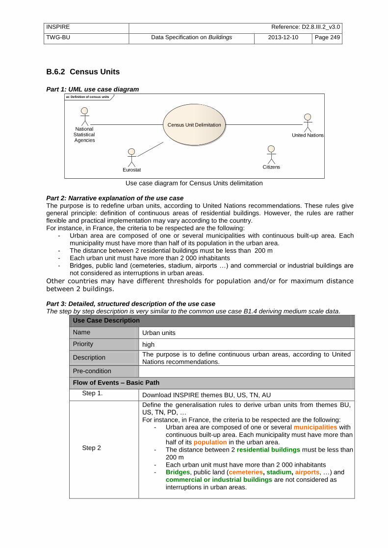
INSPIRE Reference: D2.8.III.2_v3.0
TWG-BU Data Specification on Buildings 2013-12-10 Page 249
B.6.2 Census Units
Part 1: UML use case diagram
uc Definition of census units
Census Unit Delimitation
Eurostat
National Statistical Agencies
Citizens
United Nations
Use case diagram for Census Units delimitation
Part 2: Narrative explanation of the use case The purpose is to redefine urban units, according to United Nations recommendations. These rules give general principle: definition of continuous areas of residential buildings. However, the rules are rather flexible and practical implementation may vary according to the country. For instance, in France, the criteria to be respected are the following:
- Urban area are composed of one or several municipalities with continuous built-up area. Each municipality must have more than half of its population in the urban area.
- The distance between 2 residential buildings must be less than 200 m - Each urban unit must have more than 2 000 inhabitants - Bridges, public land (cemeteries, stadium, airports …) and commercial or industrial buildings are
not considered as interruptions in urban areas.
Other countries may have different thresholds for population and/or for maximum distance
between 2 buildings. Part 3: Detailed, structured description of the use case The step by step description is very similar to the common use case B1.4 deriving medium scale data.
Use Case Description
Name Urban units
Priority high
Description The purpose is to define continuous urban areas, according to United Nations recommendations.
Pre-condition
Flow of Events – Basic Path
Step 1. Download INSPIRE themes BU, US, TN, AU
Step 2
Define the generalisation rules to derive urban units from themes BU, US, TN, PD, … For instance, in France, the criteria to be respected are the following:
- Urban area are composed of one or several municipalities with continuous built-up area. Each municipality must have more than half of its population in the urban area.
- The distance between 2 residential buildings must be less than 200 m
- Each urban unit must have more than 2 000 inhabitants - Bridges, public land (cemeteries, stadium, airports, …) and
commercial or industrial buildings are not considered as interruptions in urban areas.

INSPIRE Reference: D2.8.III.2_v3.0
TWG-BU Data Specification on Buildings 2013-12-10 Page 250
Use Case Description
Step 3 Run the generalisation rules on large scale data.
Result The geometry of the urban units is defined and is available for theme SU
Data source: <Name> [repeat per data source]
Description INSPIRE themes BU, US, TN, ..
Geographic scope Everywhere in Europe

INSPIRE Reference: D2.8.III.2_v3.0
TWG-BU Data Specification on Buildings 2013-12-10 Page 251
Annex C (normative)
Code list values
INSPIRE Application Schema 'BuildingsBase'
Code List
BuildingNatureValue
ConditionOfConstructionValue
CurrentUseValue
ElevationReferenceValue
HeightStatusValue
HorizontalGeometryReferenceValue
BuildingNatureValue
Name: Building nature value Definition: Values indicating the nature of a building. Description: NOTE 1 : This code list does not aim to be exhaustive as the attribute
buildingNature addresses only noticeable buildings. NOTE 2: The values included in this code list address mainly (but not only) two international use cases: air flights where buildings may be obstacles and marine navigation where buildings may be landmarks. NOTE 3: This code list should only be applied for buildings, even if it may be applicable to other constructions (for example, not all dams are buildings).
Extensibility: open
Identifier: http://inspire.ec.europa.eu/codelist/BuildingNatureValue Values: The allowed values for this code list comprise the values specified in the table
below and additional values at any level defined by data providers.
arch
Name: arch
Definition: A man-made structure in the form of an arch.
bunker
Name: bunker
Definition: A facility, partly underground, intended for or used by the military either for location of command/control centers or for troop encampment.
canopy
Name: canopy
Definition: An overhead roof providing shelter to things below. Canopies may be free standing frameworks over which a covering is attached or may be linked or suspended to the outside of a building.
caveBuilding
Name: cave building Definition: A space hosting human or economic activity which is usually enclosed within
rock with the addition of man-made exterior walls and which may contain structures comparable to the interior structures of freestanding buildings.
chapel
Name: chapel

INSPIRE Reference: D2.8.III.2_v3.0
TWG-BU Data Specification on Buildings 2013-12-10 Page 252
Definition: A Christian place of worship, usually smaller than a church.
castle
Name: castle
Definition: A large ornate or fortified building usually constructed for the purpose of a private residence or security.
church
Name: church
Definition: A building or structure whose primary purpose is to facilitate the catholic or orthodox cult.
dam
Name: dam
Definition: A permanent barrier across a watercourse used to impound water or to control its flow.
greenhouse
Name: greenhouse
Definition: A building that is often constructed primarily of transparent material (for example: glass), in which temperature and humidity can be controlled for the cultivation and/or protection of plants.
lighthouse
Name: lighthouse
Definition: A tower designed to emit light from a system of lamps and lenses.
mosque
Name: mosque
Definition: A building or structure whose primary purpose is to facilitate the muslim cult.
shed
Name: shed
Definition: A building of light construction, which usually has one or more open sides, that is typically used for storage.
silo
Name: silo
Definition: A large storage structure, generally cylindrical, used for storing loose materials.
stadium
Name: stadium
Definition: A place or venue for sports, concerts or other events and consists of a field or stage either partly or completely surrounded by a structure designed to allow spectators to stand or sit and view the event.
storageTank
Name: storage tank Definition: A container usually for holding liquids and compressed gases.
synagogue
Name: synagogue
Definition: A building or structure whose primary purpose is to facilitate the israelit cult.
temple
Name: temple
Definition: A building or structure whose primary purpose is to facilitate the meeting of a religious sect.
tower
Name: tower
Definition: A relatively tall, narrow structure that may either stand alone or may form part of another structure.
windmill
Name: windmill

INSPIRE Reference: D2.8.III.2_v3.0
TWG-BU Data Specification on Buildings 2013-12-10 Page 253
Definition: A building which converts the energy of the wind into rotational motion by means of adjustable sails or blades.
windTurbine
Name: wind turbine
Definition: A tower and associated equipment that generates electrical power from wind.
ConditionOfConstructionValue
Name: Condition of construction value
Definition: Values indicating the condition of a construction.
Extensibility: none
Identifier: http://inspire.ec.europa.eu/codelist/ConditionOfConstructionValue
Values: The allowed values for this code list comprise only the values specified in the table below.
declined
Name: declined
Definition: The construction cannot be used under normal conditions, though its main elements (walls, roof) are still present.
Description: EXAMPLE: A house whose windows have been for a long time broken or walled up (even if occupied by squatters).
demolished
Name: demolished
Definition: The construction has been demolished. There are no more visible remains.
functional
Name: functional
Definition: The construction is functional.
Description: NOTE: The construction may be used under normal conditions for its current use value(s).
projected
Name: projected
Definition: The construction is being designed. Construction has not yet started.
ruin
Name: ruin
Definition: The construction has been partly demolished and some main elements (roof, walls) have been destroyed. There are some visible remains of the construction.
underConstruction
Name: under construction
Definition: The construction is under construction and not yet functional. This applies only to the initial construction of the construction and not to maintenance work.
CurrentUseValue
Name: Current use value
Definition: List of possible values indicating the current use.
Description: SOURCE: This code list is partly based on and adapted from the Eurostat classification of types of constructions (for the classification of residential buildings). NOTE: the values of this code list apply to buildings or building components where building components may be a building part (in core profiles) or a building unit (in extended profiles)
Extensibility: narrower
Identifier: http://inspire.ec.europa.eu/codelist/CurrentUseValue
Values: The allowed values for this code list comprise the values specified in the table below and

INSPIRE Reference: D2.8.III.2_v3.0
TWG-BU Data Specification on Buildings 2013-12-10 Page 254
narrower values defined by data providers.
residential
Name: residential
Definition: The building (or building component) is used for residential purpose.
individualResidence
Name: individual residence
Definition: The building (or building component) hosts only one dwelling.
Description: "NOTE: This value includes detached houses such as bungalows, villas, chalets, forest lodges, farmhouses, country houses, summer houses, weekend houses and semi-detached or terraced houses, with each dwelling having its own roof and its own entrance directly from ground surface."
Parent: residential
collectiveResidence
Name: collective residence
Definition: The building (or building component) hosts more than one dwelling.
Parent: residential
twoDwellings
Name: two dwellings
Definition: The building (or building component) hosts two dwellings.
Description: "NOTE: This class includes detached houses, semi-detached or terraced houses, with two dwellings."
Parent: collectiveResidence
moreThanTwoDwelling
Name: more than two dwellings
Definition: The building (or building component) hosts at least 3 dwellings.
Description: "NOTE: This class includes flat blocks, apartment houses, with three or more dwellings but excludes residence for communities."
Parent: collectiveResidence
residenceForCommunities
Name: residence for communities
Definition: The building (or building component) hosts a residence for communities.
Description: "This class includes residential buildings for communities, including residences and service residences for the elderly, students, children and other social groups."
Parent: residential
agriculture
Name: agriculture
Definition: The building (or building component) is used for agricultural activities.
industrial
Name: industrial
Definition: The building (or building component) is used for secondary sector activities (industrial).
commerceAndServices
Name: commerce and services
Definition: The building (or building component) is used for any service activities. This value addresses the buildings and building components dedicated to tertiary sector activities (commercial and services).
Description: "NOTE: This value includes both ternary sector (commercial activities) and quaternary sector (non-commercial, charity sector)."
office
Name: office
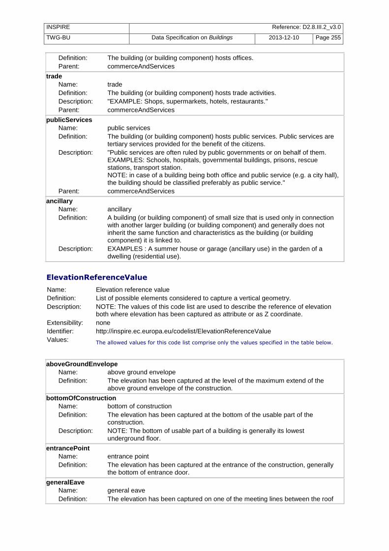
INSPIRE Reference: D2.8.III.2_v3.0
TWG-BU Data Specification on Buildings 2013-12-10 Page 255
Definition: The building (or building component) hosts offices.
Parent: commerceAndServices
trade
Name: trade
Definition: The building (or building component) hosts trade activities.
Description: "EXAMPLE: Shops, supermarkets, hotels, restaurants." Parent: commerceAndServices
publicServices
Name: public services
Definition: The building (or building component) hosts public services. Public services are tertiary services provided for the benefit of the citizens.
Description: "Public services are often ruled by public governments or on behalf of them. EXAMPLES: Schools, hospitals, governmental buildings, prisons, rescue stations, transport station. NOTE: in case of a building being both office and public service (e.g. a city hall), the building should be classified preferably as public service."
Parent: commerceAndServices
ancillary
Name: ancillary
Definition: A building (or building component) of small size that is used only in connection with another larger building (or building component) and generally does not inherit the same function and characteristics as the building (or building component) it is linked to.
Description: EXAMPLES : A summer house or garage (ancillary use) in the garden of a dwelling (residential use).
ElevationReferenceValue
Name: Elevation reference value
Definition: List of possible elements considered to capture a vertical geometry.
Description: NOTE: The values of this code list are used to describe the reference of elevation both where elevation has been captured as attribute or as Z coordinate.
Extensibility: none
Identifier: http://inspire.ec.europa.eu/codelist/ElevationReferenceValue
Values: The allowed values for this code list comprise only the values specified in the table below.
aboveGroundEnvelope
Name: above ground envelope
Definition: The elevation has been captured at the level of the maximum extend of the above ground envelope of the construction.
bottomOfConstruction
Name: bottom of construction
Definition: The elevation has been captured at the bottom of the usable part of the construction.
Description: NOTE: The bottom of usable part of a building is generally its lowest underground floor.
entrancePoint
Name: entrance point
Definition: The elevation has been captured at the entrance of the construction, generally the bottom of entrance door.
generalEave
Name: general eave
Definition: The elevation has been captured on one of the meeting lines between the roof

INSPIRE Reference: D2.8.III.2_v3.0
TWG-BU Data Specification on Buildings 2013-12-10 Page 256
and the walls.
Description: "NOTE: in case of a roof having a symetry axis, values generalEave, lowestEave and highestEave are equivalent."
generalGround
Name: general ground
Definition: The elevation has been captured on one of the meeting lines between the construction and the ground.
Description: "NOTE: In case of buildings located on flat areas, values generalGround, lowestGroundPoint and highestGroundPoint are equivalent."
generalRoof
Name: general roof
Definition: The elevation has been captured anywhere on the roof.
generalRoofEdge
Name: general roof Edge
Definition: The elevation has been captured on one of the roof edges.
Description: "NOTE: in case of a roof having a symetry axis, values generalRoofEdge, lowestRoofEdge and highestRoofEdge are equivalent."
highestEave
Name: highest eave
Definition: The elevation has been captured on the highest meeting line between the roof and the walls.
highestGroundPoint
Name: highest ground Point
Definition: The elevation has been captured on the highest point of the meeting lines between the construction and the ground.
highestPoint
Name: highest point
Definition: The elevation has been captured at the highest point of the construction, including the installations, such as chimneys and antennas.
highestRoofEdge
Name: highest roof edge
Definition: The elevation has been captured at the highest roof edge level of the construction.
lowestEave
Name: lowest eave
Definition: The elevation has been captured on the lowest meeting line between the roof and the walls.
lowestFloorAboveGround
Name: lowest floor above ground
Definition: The elevation has been captured at the level of the lowest floor above ground of the construction.
Description: This value is of interest for over-hanging buildings or for buildings on pilotis.
lowestGroundPoint
Name: lowest ground point
Definition: The elevation has been captured on the lowest point of the meeting lines between the construction and the ground.
lowestRoofEdge
Name: lowest roof edge
Definition: The elevation has been captured at the lowest roof edge level of theconstruction.
topOfConstruction
Name: top of construction
Definition: The elevation has been captured at the top level of the construction.
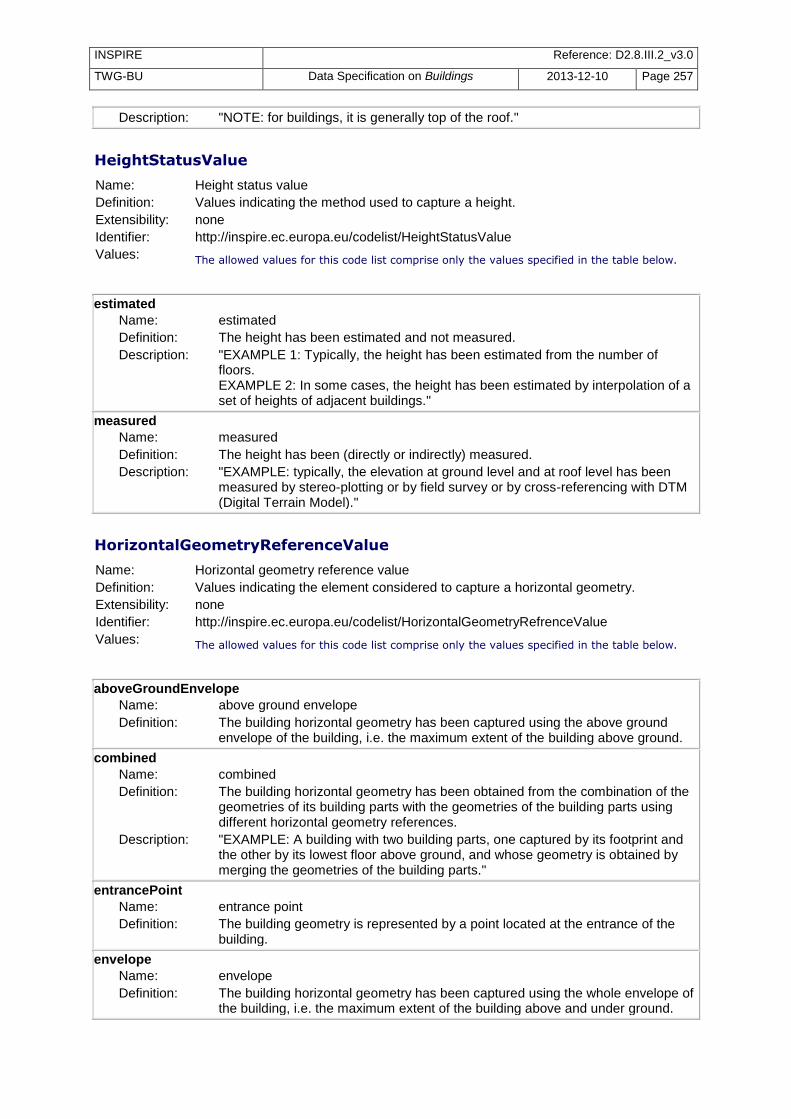
INSPIRE Reference: D2.8.III.2_v3.0
TWG-BU Data Specification on Buildings 2013-12-10 Page 257
Description: "NOTE: for buildings, it is generally top of the roof."
HeightStatusValue
Name: Height status value
Definition: Values indicating the method used to capture a height.
Extensibility: none
Identifier: http://inspire.ec.europa.eu/codelist/HeightStatusValue
Values: The allowed values for this code list comprise only the values specified in the table below.
estimated
Name: estimated
Definition: The height has been estimated and not measured.
Description: "EXAMPLE 1: Typically, the height has been estimated from the number of floors. EXAMPLE 2: In some cases, the height has been estimated by interpolation of a set of heights of adjacent buildings."
measured
Name: measured
Definition: The height has been (directly or indirectly) measured.
Description: "EXAMPLE: typically, the elevation at ground level and at roof level has been measured by stereo-plotting or by field survey or by cross-referencing with DTM (Digital Terrain Model)."
HorizontalGeometryReferenceValue
Name: Horizontal geometry reference value
Definition: Values indicating the element considered to capture a horizontal geometry.
Extensibility: none
Identifier: http://inspire.ec.europa.eu/codelist/HorizontalGeometryRefrenceValue
Values: The allowed values for this code list comprise only the values specified in the table below.
aboveGroundEnvelope
Name: above ground envelope
Definition: The building horizontal geometry has been captured using the above ground envelope of the building, i.e. the maximum extent of the building above ground.
combined
Name: combined
Definition: The building horizontal geometry has been obtained from the combination of the geometries of its building parts with the geometries of the building parts using different horizontal geometry references.
Description: "EXAMPLE: A building with two building parts, one captured by its footprint and the other by its lowest floor above ground, and whose geometry is obtained by merging the geometries of the building parts."
entrancePoint
Name: entrance point
Definition: The building geometry is represented by a point located at the entrance of the building.
envelope
Name: envelope
Definition: The building horizontal geometry has been captured using the whole envelope of the building, i.e. the maximum extent of the building above and under ground.
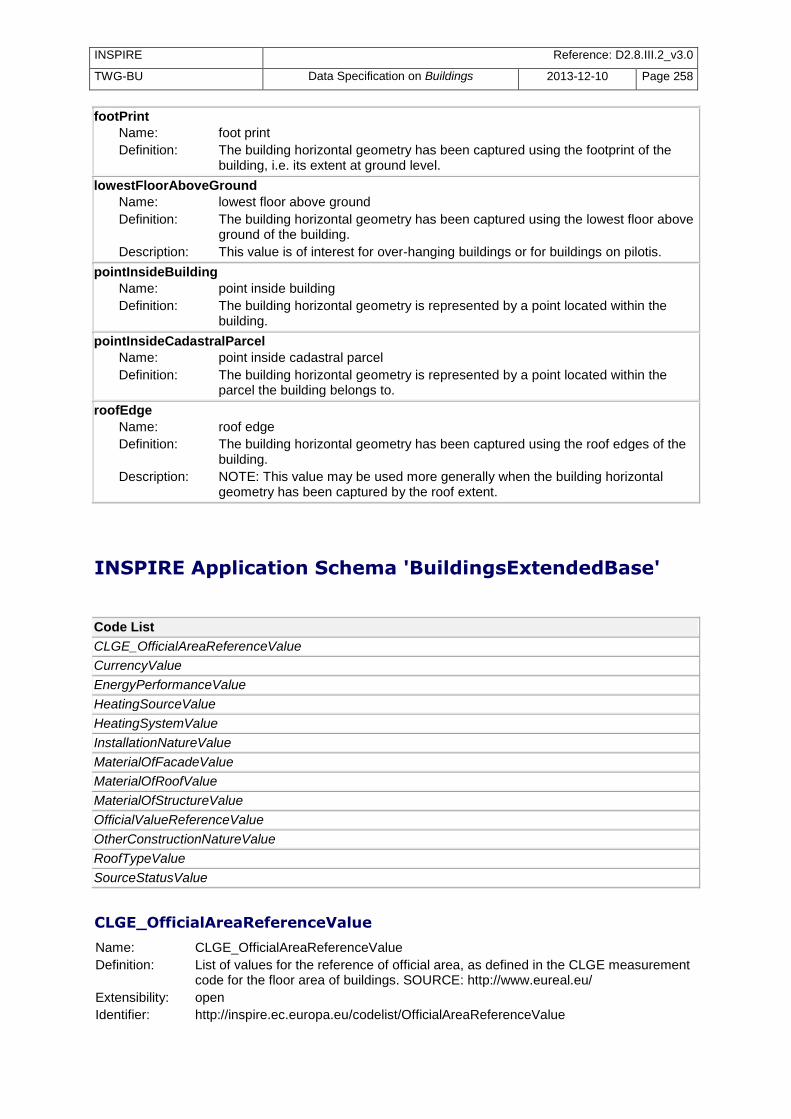
INSPIRE Reference: D2.8.III.2_v3.0
TWG-BU Data Specification on Buildings 2013-12-10 Page 258
footPrint
Name: foot print
Definition: The building horizontal geometry has been captured using the footprint of the building, i.e. its extent at ground level.
lowestFloorAboveGround
Name: lowest floor above ground
Definition: The building horizontal geometry has been captured using the lowest floor above ground of the building.
Description: This value is of interest for over-hanging buildings or for buildings on pilotis.
pointInsideBuilding
Name: point inside building
Definition: The building horizontal geometry is represented by a point located within the building.
pointInsideCadastralParcel
Name: point inside cadastral parcel
Definition: The building horizontal geometry is represented by a point located within the parcel the building belongs to.
roofEdge
Name: roof edge
Definition: The building horizontal geometry has been captured using the roof edges of the building.
Description: NOTE: This value may be used more generally when the building horizontal geometry has been captured by the roof extent.
INSPIRE Application Schema 'BuildingsExtendedBase'
Code List
CLGE_OfficialAreaReferenceValue
CurrencyValue
EnergyPerformanceValue
HeatingSourceValue
HeatingSystemValue
InstallationNatureValue
MaterialOfFacadeValue
MaterialOfRoofValue
MaterialOfStructureValue
OfficialValueReferenceValue
OtherConstructionNatureValue
RoofTypeValue
SourceStatusValue
CLGE_OfficialAreaReferenceValue
Name: CLGE_OfficialAreaReferenceValue
Definition: List of values for the reference of official area, as defined in the CLGE measurement code for the floor area of buildings. SOURCE: http://www.eureal.eu/
Extensibility: open
Identifier: http://inspire.ec.europa.eu/codelist/OfficialAreaReferenceValue

INSPIRE Reference: D2.8.III.2_v3.0
TWG-BU Data Specification on Buildings 2013-12-10 Page 259
Values:
The table below includes recommended values that may be used by data providers. Before creating new terms, please check if one of them can be used. constructedArea
Name: constructed area Definition: Constructed area is the difference between the external area and the
internal area of the building or building unit. Description: NOTE: Constructed area is mainly used as technical data.
externalArea
Name: external area Definition: External area is the area within the outer perimeter boundary of a
building or building unit, including any outer cladding, measured at floor level.
Description: NOTE: External area is mainly used for spatial planning purpose.
internalArea
Name: internal area Definition: Internal area is the area within the interior perimeter of a building or
building unit, measured above skirting-board level. Description: "Internal area is mainly used as reference unit of measure in valuation,
property transaction, renting and building management."
internalPrimaryArea
Name: internal primary area Definition: Internal primary area is the sum of all floor areas with a heightroom
superior or equal to heightParameter and that are associated with the principal uses of the building.
Description: "Internal primary area includes: - in housing: living areas (dining rooms, bedrooms), toilet, areas (bathrooms, lavatories), interior space and passageways, storage areas... - in offices: work areas, meeting rooms, annexes, recreational areas, toilets, interior space and passageways..."
internalOtherArea
Name: internal other area Definition: Internal other area is the sum of all floor areas with a heightroom <
heightParameter and that are associated with the main uses of the building.
Description: "Internal other areas includes in particular garages, passageways and non-enclosed covered area (canopies, car-ports, ...)."
internalResidualArea
Name: internal residual area Definition: Internal residual area is the sum of all floor areas regardless of height
that are not consistent with the principal use of the building. Description: "Internal residual area includes in particular underground storage and
archive rooms, cellars, parking garage, balconies, upper floor terraces, loggias."
internalServiceArea
Name: internal service area Definition: Internal service area is the sum of all floor areas used for building
services, irrespective of their height or occupation. Description: "Internal service area includes in particular lift shafts, stairwells, access
ramps, maintenance and technical areas serving the building."
CurrencyValue

INSPIRE Reference: D2.8.III.2_v3.0
TWG-BU Data Specification on Buildings 2013-12-10 Page 260
Name: CurrencyValue
Definition: Code list for possible values of attribute currency
Description: NOTE 1: include currencies from all European countries, including that are not Member States of European Union. SOURCE: values are extracted from ISO 4217 standard. NOTE 2: this code list may be of interest not only for INSPIRE but also for other European applications and regulations ; so, in future, this code list might/should be managed outside INSPIRE.
Extensibility: open
Identifier: http://inspire.ec.europa.eu/codelist/CurrencyValue
Values:
The table below includes recommended values that may be used by data providers. Before creating new terms, please check if one of them can be used. ALL
Name: ALL Definition: Lek (in Albania)
BAM
Name: BAM Definition: Convertible Mark (in Bosnia & Herzegovina)
BGN
Name: BGN Definition: Bulgarian Lev (in Bulgaria)
BYR
Name: BYR Definition: Belarussian Ruble (in Belarus)
CHE
Name: CHE Definition: WIR Euro (in Switzerland). Description: "NOTE: """"WIR"""" is both an abbreviation of """"Wirtschaftsring
Genossenschaft"""" and the word for """"we"""" in German, reminding participants that the economic circle is also a community."
CHF
Name: CHF Definition: Swiss Franc (in Switzerland and Liechtenstein)
CZK
Name: CZK Definition: Czech Koruna (in Czech Republic)
DKK
Name: DKK Definition: Danish Krone (in Denmark)
EUR
Name: EUR Definition: euro
GBP
Name: GBP Definition: Pound Sterling (in United Kingdom)
HRK
Name: HRK Definition: Croatian Kuna (in Croatia)
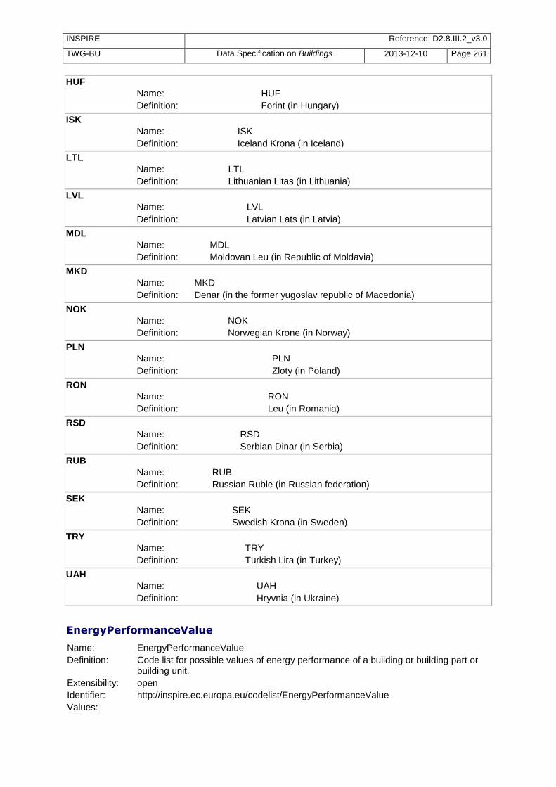
INSPIRE Reference: D2.8.III.2_v3.0
TWG-BU Data Specification on Buildings 2013-12-10 Page 261
HUF
Name: HUF Definition: Forint (in Hungary)
ISK
Name: ISK Definition: Iceland Krona (in Iceland)
LTL
Name: LTL Definition: Lithuanian Litas (in Lithuania)
LVL
Name: LVL Definition: Latvian Lats (in Latvia)
MDL
Name: MDL Definition: Moldovan Leu (in Republic of Moldavia)
MKD
Name: MKD Definition: Denar (in the former yugoslav republic of Macedonia)
NOK
Name: NOK Definition: Norwegian Krone (in Norway)
PLN
Name: PLN Definition: Zloty (in Poland)
RON
Name: RON Definition: Leu (in Romania)
RSD
Name: RSD Definition: Serbian Dinar (in Serbia)
RUB
Name: RUB Definition: Russian Ruble (in Russian federation)
SEK
Name: SEK Definition: Swedish Krona (in Sweden)
TRY
Name: TRY Definition: Turkish Lira (in Turkey)
UAH
Name: UAH Definition: Hryvnia (in Ukraine)
EnergyPerformanceValue
Name: EnergyPerformanceValue
Definition: Code list for possible values of energy performance of a building or building part or building unit.
Extensibility: open
Identifier: http://inspire.ec.europa.eu/codelist/EnergyPerformanceValue
Values:

INSPIRE Reference: D2.8.III.2_v3.0
TWG-BU Data Specification on Buildings 2013-12-10 Page 262
The table below includes recommended values that may be used by data providers. Before creating new terms, please check if one of them can be used. A
Name: A Definition: First class according to the energy performance of the building (i.e. the
most efficient buildings for energy performance).
B
Name: B Definition: Second class according to the energy performance of the building.
C
Name: C Definition: Third class according to the energy performance of the building.
D
Name: D Definition: Fourth class according to the energy performance of the building.
E
Name: E Definition: Fifth class according to the energy performance of the building.
F
Name: F Definition: Sixth class according to the energy performance of the building.
G
Name: G Definition: Seventh and last class according to the energy performance of the
building (i.e. the least efficient buildings for energy performance).
HeatingSourceValue
Name: HeatingSourceValue
Definition: Code list for the possible values of the heating source of a building, building part or building unit.
Extensibility: open
Identifier: http://inspire.ec.europa.eu/codelist/HeatingSourceValue
Values:
The table below includes recommended values that may be used by data providers. Before creating new terms, please check if one of them can be used. biogas
Name: biogas Definition: The heating source is biogas. Description: Biogas may come from a local biogas plant or more rarely be produced
on a household scale.
electricity
Name: electricity Definition: The heating source is electricity distributed from power plant.
liquidFuels
Name: liquid fuels Definition: The heating source is liquid fuel. Description: "Liquid fuels include all sorts of liquids, petroleum, fuel oil etc."
naturalGas
Name: natural gas

INSPIRE Reference: D2.8.III.2_v3.0
TWG-BU Data Specification on Buildings 2013-12-10 Page 263
Definition: The heating source is fossil gas distributed by pipeline.
solidFuels
Name: solid fuels Definition: The heating source is solid fuel. Description: "Solid fuels include wood, charcoal, peat, coal, tablets and pellets made
from wood."
straw
Name: straw Definition: The heating source is solid biofuels from straw and agricultural waste.
warmWaterOrStream
Name: warm water or stream Definition: The heating source used by the building or building unit is hot water or
stream. Description: Warm water or stream is generally distributed by central district heating.
HeatingSystemValue
Name: HeatingSystemValue
Definition: Code list giving the possible values for the heating system of a building, building part or building unit.
Extensibility: open
Identifier: http://inspire.ec.europa.eu/codelist/HeatingSystemValue
Values:
The table below includes recommended values that may be used by data providers. Before creating new terms, please check if one of them can be used. centralHeating
Name: central heating Definition: Central heating system performed at building or at building unit level.
districtHeating
Name: district heating Definition: Central heating system, based on district heating. Description: The public heat network is connected to the central heating of the
building by a heat exchanger. The warm water or steam used in the district heating system is not mixed with the water of the central heating system in the building.
electricRaditors
Name: electric radiators Definition: Heating is performed by electric radiators. Description: Electric radiators could be single portable units or an integrated
installation of the building.
heatPump
Name: heat pump Definition: The heating is performed by a heat pump that transfers thermal energy
from an air source or geothermal source. Description: The device is sometimes connected to the central heating system in the
building.
portableGasHeating
Name: portable gas heating Definition: Heating is performed by a portable device using liquefied petroleum gas.
solarHeating
Name: solar heating
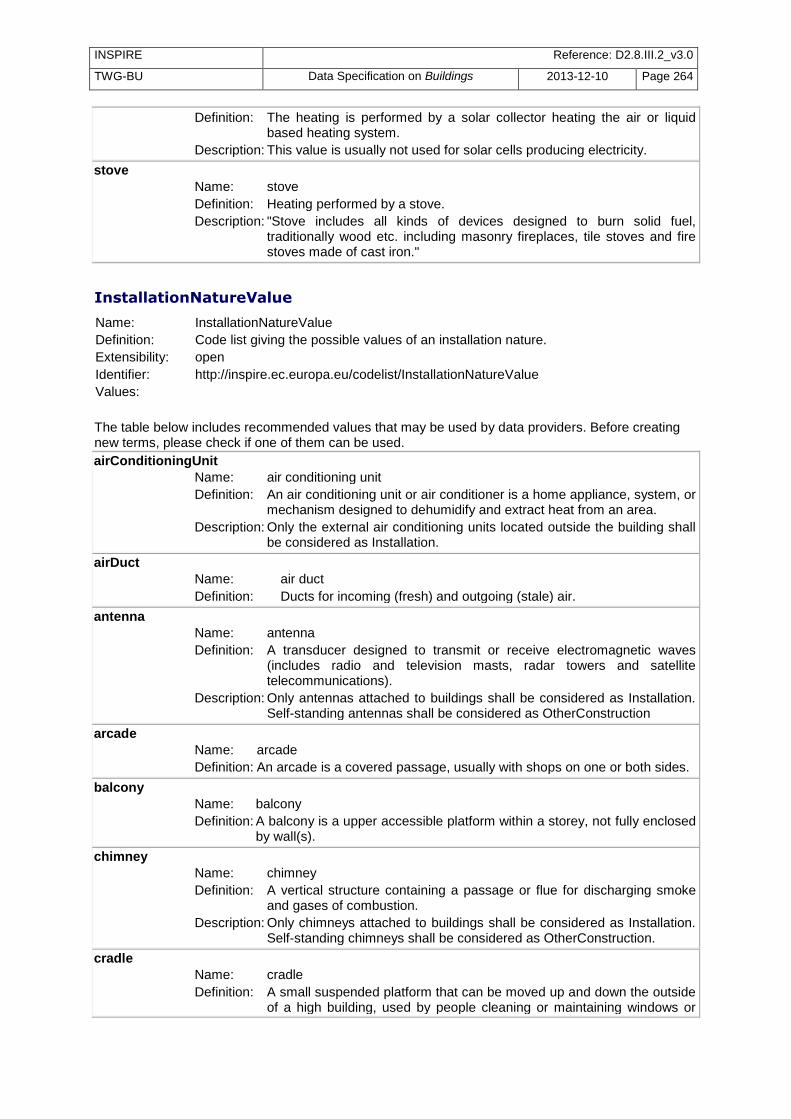
INSPIRE Reference: D2.8.III.2_v3.0
TWG-BU Data Specification on Buildings 2013-12-10 Page 264
Definition: The heating is performed by a solar collector heating the air or liquid based heating system.
Description: This value is usually not used for solar cells producing electricity.
stove
Name: stove Definition: Heating performed by a stove. Description: "Stove includes all kinds of devices designed to burn solid fuel,
traditionally wood etc. including masonry fireplaces, tile stoves and fire stoves made of cast iron."
InstallationNatureValue
Name: InstallationNatureValue
Definition: Code list giving the possible values of an installation nature.
Extensibility: open
Identifier: http://inspire.ec.europa.eu/codelist/InstallationNatureValue
Values:
The table below includes recommended values that may be used by data providers. Before creating new terms, please check if one of them can be used. airConditioningUnit
Name: air conditioning unit Definition: An air conditioning unit or air conditioner is a home appliance, system, or
mechanism designed to dehumidify and extract heat from an area. Description: Only the external air conditioning units located outside the building shall
be considered as Installation.
airDuct
Name: air duct Definition: Ducts for incoming (fresh) and outgoing (stale) air.
antenna
Name: antenna Definition: A transducer designed to transmit or receive electromagnetic waves
(includes radio and television masts, radar towers and satellite telecommunications).
Description: Only antennas attached to buildings shall be considered as Installation. Self-standing antennas shall be considered as OtherConstruction
arcade
Name: arcade Definition: An arcade is a covered passage, usually with shops on one or both sides.
balcony
Name: balcony Definition: A balcony is a upper accessible platform within a storey, not fully enclosed
by wall(s).
chimney
Name: chimney Definition: A vertical structure containing a passage or flue for discharging smoke
and gases of combustion. Description: Only chimneys attached to buildings shall be considered as Installation.
Self-standing chimneys shall be considered as OtherConstruction.
cradle
Name: cradle Definition: A small suspended platform that can be moved up and down the outside
of a high building, used by people cleaning or maintaining windows or

INSPIRE Reference: D2.8.III.2_v3.0
TWG-BU Data Specification on Buildings 2013-12-10 Page 265
facades, etc. Description: The cradles that are permanently installed in a building and may be used
for emergency evacuation are of interest for INSPIRE.
dormer
Name: dormer Definition: A dormer is a structural element of a building that protrudes from the plane
of a sloping roof surface. Dormers are used, either in original construction or as later additions, to create usable space in the roof of a building by adding headroom and usually also by enabling addition of windows.
externalLift
Name: external lift Definition: Lift moving along the outside of a building.
railing
Name: railing Definition: A handrail is a rail that is designed to be grasped by the hand so as to
provide stability or support.
ramp
Name: ramp Definition: A ramp is an inclined plane installed in addition to or instead of stairs. A
ramp may generally be used by wheelchairs.
solarPanel
Name: solar panel Definition: A solar panel is a packaged, connected assembly of solar cells, also
known as photovoltaic cells. The solar panel can be used as a component of a larger photovoltaic system to generate and supply electricity in commercial and residential applications.
Description: Only the solar panels attached to the building should be considered as installations. The self-standing solar panels should be classified under OtherConstruction.
stairway
Name: stairway Definition: Stairway is a construction designed to bridge a large vertical distance by
dividing it into smaller vertical distances, called steps. Stairways may be straight, round, or may consist of two or more straight pieces connected at angles.
tower
Name: tower Definition: A relatively tall, narrow structure that may either stand alone or may form
part of another structure. Description: "May be considered as installations only the small towers that form part
of a building, especially if they are not attached to the ground. More significant and/or more independent towers shall be considered as Building or BuildingPart."
windTurbine
Name: wind turbine Definition: A device that converts kinetic energy from the wind into mechanical
energy. Description: Only the (generally small) wind turbines attached to or serving a building
shall be classified under installations. The self-standing and generally big wind-turbines shall be classified under Building.
MaterialOfFacadeValue
Name: MaterialOfFacadeValue

INSPIRE Reference: D2.8.III.2_v3.0
TWG-BU Data Specification on Buildings 2013-12-10 Page 266
Definition: Code list for the possible values of MaterialOfFacade
Extensibility: open
Identifier: http://inspire.ec.europa.eu/codelist/MaterialOfFacadeValue
Values:
The table below includes recommended values that may be used by data providers. Before creating new terms, please check if one of them can be used. adobe
Name: adobe Definition: Use of a particular type of masonry for the fa?ade, that involves the use of
clay bricks (adobe) formed in moulds and (traditionally) dried in the sun.
asbestos
Name: asbestos Definition: Fa?ade constructed out of asbestos.
ceramicTiles
Name: ceramic tiles Definition: Ceramic tiles of different colours and design are used for covering the
fa?ade of the building. Description: EXAMPLES: ceramic tiles are commonly used in Portugal.
composite
Name: composite Definition: Composite material, such as plastics, PVC and fibreglass are used to
cover the fa?ade of the building.
concrete
Name: concrete Definition: The surface of the fa?ade is constructed out of (reinforced, with bars or
fibres-other than asbestos) concrete.
glass
Name: glass Definition: Known as structural glass, is used for glazing the fa?ade of buildings
through the use of curtain wall systems, frameless glazing systems, polycarbonate sheeting or architectural flat glass.
limestone
Name: limestone Definition: The fa?ade of the building is composed of limestone, a sedimentary rock
composed largely of calcite and/or aragonite. Description: "Limestone was commonly used for the construction of many medieval
churches and castles in Europe, it was widely used in the 19th and early 20th centuries, and in countries like Malta, for a long time, the only building material available."
masonry
Name: masonry Definition: The fa?ade consists of individual units made of fired clay brick or concrete
block laid in and bound together by mortar.
metal
Name: metal Definition: The surface of the building is covered with metal in the form of galvanized
steel with paint, aluminium with paint, stainless steel, zinc, lead or copper.
naturalStone
Name: natural stone Definition: The fa?ade is covered with natural stone, such as granite or marble, and
may come in different colours and finishing. Description: "NOTE: If the fa?ade is covered by limestone (that is also natural stone),
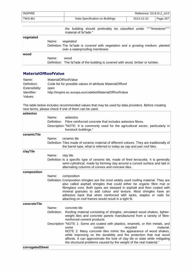
INSPIRE Reference: D2.8.III.2_v3.0
TWG-BU Data Specification on Buildings 2013-12-10 Page 267
the building should preferably be classified under """"limestone"""" material of fa?ade."
vegetated
Name: vegetated Definition: The fa?ade is covered with vegetation and a growing medium, planted
over a waterproofing membrane
wood
Name: wood Definition: The fa?ade of the building is covered with wood, timber or lumber.
MaterialOfRoofValue
Name: MaterialOfRoofValue
Definition: Code list for possible values of attribute MaterialOfRoof
Extensibility: open
Identifier: http://inspire.ec.europa.eu/codelist/MaterialOfRoofValue
Values:
The table below includes recommended values that may be used by data providers. Before creating new terms, please check if one of them can be used. asbestos
Name: asbestos Definition: Fibre reinforced concrete that includes asbestos fibres. Description: "NOTE: It is commonly used for the agricultural sector, particularly in
livestock buildings."
ceramicTile
Name: ceramic tile Definition: Tiles made of ceramic material of different colours. They are traditionally of
the barrel type, what is referred to today as cap and pan roof tiles.
clayTile
Name: clay tile Definition: Is a specific type of ceramic tile, made of fired terracotta. It is generally
semi-cylindrical, made by forming clay around a curved surface and laid in alternating columns of convex and concave tiles.
composition
Name: composition Definition: Composition shingles are the most widely used roofing material. They are
also called asphalt shingles that could either be organic fibre mat or fibreglass core. Both types are steeped in asphalt and then coated with mineral granules to add colour and texture. Most shingles have an adhesive back that when reinforced with tacks, staples or nails for attaching on roof frames would result in a tight fit.
concreteTile
Name: concrete tile Definition: Roofing material consisting of shingles, simulated wood shakes, lighter-
weight tiles and concrete panels manufactured from a variety of fibre-reinforced cement products.
Description: "NOTE 1: Some are coated with plastics, enamels, or thin metals, and some contain recycled material. NOTE 2: Many concrete tiles mimic the appearance of wood shakes, while improving on the durability and fire protection that real wood affords. It can approximate the look of clay tile or slate while mitigating the structural problems caused by the weight of the real material."
corrugatedSheet

INSPIRE Reference: D2.8.III.2_v3.0
TWG-BU Data Specification on Buildings 2013-12-10 Page 268
Name: corrugated sheet Definition: Roofs of corrugated sheet may be of fibreglass, PVC or metal; less
frequent is the use of galvanized iron sheet.
glass
Name: glass Definition: The surface of the roof is constructed out of glass, typically used in roofs
covering internal atriums or in greenhouses.
hotMoppedAsphalt
Name: hot mopped asphalt Definition: Hot mopped asphalt roofing is usually applied to flat or semi-flat
residential roofs that have good access and proper drainage. Description: NOTE: In residential use it is often covered with a layer of decorative
stone to improve the appearance.
metal
Name: metal Definition: Metal roofing comes in the form of galvanized steel with paint, aluminium
with paint, stainless steel, zinc, lead or copper. It is also manufactured in the form of imitation wood shingles.
Description: "EXAMPLE : Standing-seam steel roofing is the most popular residential metal roofing today (the term standing-seam describes the upturned edge of one metal panel that connects it to adjacent sections, creating distinctive vertical lines and a trendy historical look). NOTE 1: Metal roofing is sturdy, lightweight, and non-combustible NOTE 2: Roofs in corrugated metal should preferably be classified under corrugatedSheet."
reinforcedConcrete
Name: reinforced concrete Definition: Roofs constructed out of reinforced concrete, normally along flat or semi-
flat surfaces used in terraces or inclined roofs.
slate
Name: slate Definition: Slate is a shingle-like sliver of rock or natural stone, offering a natural
look laid out in a variety of patterns. It comes in different sizes and colours, although colours are limited to those found in nature.
Description: "NOTE: Like tile, slate can be very heavy."
thatch
Name: thatch Definition: Roofs are built by thatching, which is the craft of building a roof with dry
vegetation such as straw, water reed, sedge, rushes and heather, layering the vegetation so as to shed water away from the inner roof.
vegetatedGreenRoof
Name: vegetated green roof Definition: Also known as eco-roofs, a vegetated or green roof is a roof of a building
that is partially or completely covered with vegetation and a growing medium, planted over a waterproofing membrane. It may also include additional layers such as a root barrier and drainage and irrigation systems.
woodShinglesOrShakes
Name: wood shingles or shakes Definition: Wood shingles or shakes are differentiated by size and texture. Shingles
are cut to a specific size and have smooth finish. Shakes are rough-textures and are irregular in shape.
MaterialOfStructureValue

INSPIRE Reference: D2.8.III.2_v3.0
TWG-BU Data Specification on Buildings 2013-12-10 Page 269
Name: MaterialOfStructureValue
Definition: Code list for possible values of attribute MaterialOfStructure.
Extensibility: open
Identifier: http://inspire.ec.europa.eu/codelist/MaterialOfStructureValue
Values:
The table below includes recommended values that may be used by data providers. Before creating new terms, please check if one of them can be used. reinforcedConcrete
Name: reinforced concrete Definition: The load resisting system is made of reinforced concrete, a combination of
steel reinforcement bars embedded in concrete that act together in resisting forces. Reinforced concrete buildings may be constructed as moment resisting frames (beams and columns framing at nodes), or in combination with shear walls.
reinforcedMasonry
Name: reinforced masonry Definition: Buildings of this type have exterior walls consisting of grouted (with
concrete) masonry (clay brick or concrete block masonry) with internal reinforcing steel rods.
Description: Reinforced masonry buildings are relatively thick walled box-like structures and often have small windows and at least two mostly solid walls.
rubleStoneMasonry
Name: ruble stone masonry Definition: Ruble stone is field stone. Is a masonry technique that incorporates any
material found or recovered, such as dressed blocks, broken fragments, brick or flint.
Description: "NOTE 1: The success of rubble depends on the thickness of the wall and the strength of the binding mortar. If either is too thin, the structure will fail. As it is almost impossible to construct a thin rubble wall, owing to the irregularity of the material and the size of the gaps to be filled by the mortar, in areas or building traditions lacking dressed stone and ashlar technology, rubble walls are likely to be very thick."
steel
Name: steel Definition: The load resisting system of the building is made of structural steel, which
may be made composite with reinforced concrete at floor slabs. Steel structures may be constructed as moments resisting frames, as concentrically or eccentrically braced frames, or as spatial trusses. The members of the structure may be bolted or welded.
stoneMasonryBlock
Name: stone masonry block Definition: Consist of masonry buildings constructed with stone blocks cut from
igneous, metamorphic or sedimentary rocks. This type of buildings are generally unreinforced and may be joined with lime/cement mortar.
wood
Name: wood Definition: The load resisting system of the building is made of wood, timber or
lumber. Description: "Two systems of construction are possible, one based on a frame, the
other on a skeleton. Framing is a building technique based around structural members, usually called studs, which provide a stable frame to which interior and exterior wall coverings are attached. In skeleton houses the posts and the horizontal crossbars form a frame (whose

INSPIRE Reference: D2.8.III.2_v3.0
TWG-BU Data Specification on Buildings 2013-12-10 Page 270
strength is sometimes increased by the use of additional diagonal bracings or stiffeners) that is filled in with wood (post or frame and plank constructions) or other materials such as clay, stone, or brick. This category is also known as timber framing or half-timbered."
adobeBlockWalls
Name: adobe Block Walls Definition: Also known as moulded earth, is a building technique that involves the
use of clay bricks (adobe) formed in moulds and (traditionally) dried in the sun.
Description: "NOTE: These unbaked bricks consist of sand, sometimes gravel, clay, water and often straw or grass mixed together by hand, formed in wooden moulds and dried by the sun. When machinery is not available, earth is manually tamped in the mould; else, mechanical compression is used (manual, or motorized presses), in order to accommodate large production outputs of compressed earth blocks."
concreteBlockMasonry
Name: concrete block masonry Definition: Unreinforced concrete block masonry, with lime/cement mortar. Description: "Buildings of this type have perimeter walls, and possibly some interior
walls, constructed of unreinforced concrete blocks joined with lime/cement mortar. These perimeter walls are sometimes used as load bearing walls and have no internal reinforcing steel rods. Anchor plates are sometimes used to tie the walls to the floors and roof and are conspicuous from the outside of the structure."
earth
Name: earth Definition: Rammed earth or pneumatically impacted stabilized earth. Rammed
earth construction (also referred to as tapial in Spanish, or else, pis? de terre, in France) is conducted by erecting wooden or metal forms for the walls and filling them with a moist cement stabilized earth mix which is compacted by pounding with hand tools (with conical or flat heads) or with a mechanical compactor. Metal rebar is often added to further increase ductility.
Description: "NOTE 1: Different kinds of earth or mineral compounds are sometimes added to each earth layer for the sake of decoration. The finished walls are massive and monolithic, offering high strength, high thermal mass and high insulation. NOTE 2: High load bearing strength allows for multi-storey structures, usually based on floor decks supported by massive wood beams. NOTE 3: No surface finishing is used except for aesthetic effect."
firedBrickMasonry
Name: fired brick masonry Definition: Unreinforced fired brick masonry. Buildings of this type have perimeter
walls, and possibly some interior walls, constructed of unreinforced fired brick blocks. These perimeter walls are sometimes used as load bearing walls and have no internal reinforcing steel rods. Anchor plates are sometimes used to tie the walls to the floors and roof and are conspicuous from the outside of the structure. Unusual brick patterns may also indicate unreinforced fired brick masonry.
informalConstructions
Name: informal constructions Definition: Parts of slums/squatters. Informal constructions are non-engineered and
are built by self-builders without any professional input (i.e. neither during the design phase, nor the construction one).
Description: "NOTE 1: The whole endeavour is usually based on observation from other nearby building sites, or (in the best of cases) on labour

INSPIRE Reference: D2.8.III.2_v3.0
TWG-BU Data Specification on Buildings 2013-12-10 Page 271
experience gained by the owners during their occupation as construction builders. NOTE 2: This type of buildings are in general of low quality and have many deficiencies that make them very vulnerable to hazards."
massiveStoneMasonry
Name: massive stone masonry Definition: Massive stone masonry with lime/cement mortar. Is constructed with a
coursed double leaf masonry, with the outer layers of stonework levelled as the construction progresses and follows a well established masonry bond. The stone units are cut in regular dimensions. To improve the connection between cross walls better quality units are used for the bond in these areas.
mobileHomes
Name: mobile homes Definition: A structure designed or adapted for human habitation which is capable
of being moved from one place to another (whether by being towed, or by being transported on a motor vehicle or trailer) and any motor vehicle so designed or adapted.
Description: "NOTE 1: Railway carriages and tents do not count as mobile homes. NOTE 2: Though mobile in nature, some mobile homes are in fact installed in perennial way and should be considered as under INSPIRE scope."
mudWalls
Name: mud walls Definition: Mud walls may be made of stacked earth or poured earth. Stacked earth
consists in forming balls of plastic soil, which are freshly stacked on each other. Poured earth walls on the other hand are erected between formwork using a sandy material with coarse to fine granular particles. The ultimate finish can be natural - from the formwork- or sand blasted.
Description: "NOTE 1: The contemporary name of stacked earth is cob ( a name derived from the British Isles). Cob does not use bricks, or blocks. Instead, wall surfaces can be sculpted into smooth, sinuous forms. A cob home may have sloping walls, arches and lots of wall niches. Modern cob construction may top the walls with a concrete bond beam, use a wooden bond beam, or a separate roof frame supported on a post and beam system."
precastConcrete
Name: precast concrete Definition: Precast wall panel construction. Buildings of this type are low-rise
structures with precast reinforced concrete wall panels that are often poured on the ground and tilted into place. Roofs are often composed of either plywood sheathing or metal decking, and glass curtain walls may exist at the building perimeter.
OfficialValueReferenceValue
Name: OfficialValueReferenceValue
Definition: The list of possible values for referencing the official value of a building, building part or building unit.
Extensibility: open
Identifier: http://inspire.ec.europa.eu/codelist/OfficialValueReferenceValue
Values:
The table below includes recommended values that may be used by data providers. Before creating new terms, please check if one of them can be used.

INSPIRE Reference: D2.8.III.2_v3.0
TWG-BU Data Specification on Buildings 2013-12-10 Page 272
transactionPriceSimple
Name: transaction price simple Definition: The reference for official value is the market price for transaction (selling,
inheritance...) of the building or building unit alone.
transactionPriceMedium
Name: transaction price medium Definition: The reference for official value is the market price for transaction (selling,
inheritance, …) of the building and of the land on which the building is erected. In case of a building unit, the transaction price medium includes the building unit and the ratio of land associated to the building unit.
transactionPriceFull
Name: transaction price full Definition: The reference for official value is the market price for transaction (selling,
inheritance...) of the building and of the cadastral parcel on which the building is erected. In case of a building unit, the transaction price medium includes the building unit and the ratio of cadastral parcel associated to the building unit.
rentalIncome
Name: rental income Definition: The reference for official value is the rental income for the building or
building unit, according to market prices.
OtherConstructionNatureValue
Name: OtherConstructionNatureValue
Definition: Code list for the attribute other construction nature.
Extensibility: open
Identifier: http://inspire.ec.europa.eu/codelist/OtherConstructionNatureValue
Values:
The table below includes recommended values that may be used by data providers. Before creating new terms, please check if one of them can be used. cityWall
Name: city wall Definition: A fortification (usually historic) used to defend a city or settlement or used
to enclose settlements.
crane
Name: crane Definition: A machine for lifting, shifting and lowering objects or material by means
of a swinging boom or with the lifting apparatus supported on overhead track.
Description: Cranes that are permanently installed or used should be considered under scope of theme Buildings.
monument
Name: monument Definition: A structure erected to commemorate persons or events. Description: "The monuments that are significant by their height (such as columns,
obelisks), by their size (such as monumental stairs) or by their fame are especially expected by INSPIRE."
openAirPool
Name: open air pool Definition: A swimming-pool that is not covered. Description: Open-air pools are of interest for fire risk.

INSPIRE Reference: D2.8.III.2_v3.0
TWG-BU Data Specification on Buildings 2013-12-10 Page 273
protectiveStructure
Name: protective structure Definition: A construction providing protection against environmental hazrds, such as
avalanches, mudslides, rock falls and landslides etc.
pylon
Name: pylon Definition: Any elongated tall support structure used to support an overhead power
line.
retainingWall
Name: retaining wall Definition: A structure designed and constructed to resist the lateral pressure of soil
when there is a desired change in ground elevation that exceeds the angle of repose of the soil.
solarPanel
Name: solar panel Definition: A solar panel is a packaged, connected assembly of solar cells, also
known as photovoltaic cells. The solar panel can be used as a component of a larger photovoltaic system to generate and supply electricity in commercial and residential applications.
Description: "May be considered as other construction, the self-standing solar panels, especially if they cover a significant area. The solar panels attached to a building should be classified as installation."
substation
Name: substation Definition: Part of an electrical generation, transmission and distribution system
where voltage is transformed from high to low, or the reverse.
tunnel
Name: tunnel Definition: An underground passage that is open at both ends and usually contains a
land transportation route (for example: a road and/or a railway).
acousticFence
Name: acoustic fence Definition: Environmental noise barrier system.
antenna
Name: antenna Definition: A transducer designed to transmit or receive electromagnetic waves
(includes radio and tv masts, radar towers and satellite telecommunications).
Description: Only self-standing antennas shall be considered as OtherConstruction. Antennas attached to buildings shall be considered as Installation.
bridge
Name: bridge Definition: A structure built to span a valley, road, body of water, or other physical
obstacle, for the purpose of providing passage over the obstacle.
chimney
Name: chimney Definition: A vertical structure containing a passage or flue for discharging smoke
and gases of combustion. Description: Only self-standingchimneys shall be considered as OtherConstruction.
Chimneys attached to buildings shall be considered as Installation.
RoofTypeValue

INSPIRE Reference: D2.8.III.2_v3.0
TWG-BU Data Specification on Buildings 2013-12-10 Page 274
Name: RoofTypeValue
Definition: Code list for the possible values of attribute roofType.
Extensibility: open
Identifier: http://inspire.ec.europa.eu/codelist/RoofTypeValue
Values:
The table below includes recommended values that may be used by data providers. Before creating new terms, please check if one of them can be used. archRoof
Name: arch roof Definition: A roof taking the form of a semicircular span connected.
conicalRoof
Name: conical roof Definition: An inverted cone roof construction usually atop of a cylindrical tower.
domedRoof
Name: domed roof Definition: Roof formed of a thin curved structural slab. Description: "NOTE: a slab is a thick, flat or shaped component usually larger than
300 mm square, used to form a covering or projecting from a building."
dualPentRoof
Name: dual Pent roof Definition: A roof that has two or more single plane roofs, usually separated or
connected by vertical walls.
flatRoof
Name: flat roof Definition: Roof either horizontal or with a slope of 10? or less.
gabledRoof
Name: gabled roof Definition: Pitched roof that terminates at one or both ends as a gable. Description: NOTE 1: a pitched roof is a roof whose slope is greater than 10?
(approximately 15 %) NOTE 2: a gable is portion of a wall above the level of the eaves that encloses the end of the space under a pitched roof
halfHippedRoof
Name: half Hipped roof Definition: A roof where all planes slope down to the supporting walls but with the
upper point of the gable squared off.
hippedRoof
Name: hipped roof Definition: Pitched roof with hip end or ends. Description: NOTE 1: a pitched roof is a roof whose slope is greater than 10?
(approximately 15 %) NOTE 2: a hip is the inclined meeting line of two inclined planes in a pitched roof which forms a salient angle
hyperbolicParabaloidalRoof
Name: hyperbolic parabaloidal roof Definition: A roof constructed with two axes with one plane following a convex curve
and another a concave curve.
mansardRoof
Name: mansard roof Definition: Pitched roof with two inclined planes on each side of the ridge , the
steeper of the two starting at the eaves Description: NOTE 1: A ridge is the intersection at the top of two inclined planes in a

INSPIRE Reference: D2.8.III.2_v3.0
TWG-BU Data Specification on Buildings 2013-12-10 Page 275
pitched roof which forms the apex of the roof. NOTE 2: Eave is lower edge of a pitched roof or edge of a flat roof.
monopitchRoof
Name: monopitch roof Definition: Pitched roof that has only a single plane. Description: NOTE: a pitched roof is a roof whose slope is greater than 10?
(approximately 15 %).
pavilionRoof
Name: pavilion roof Definition: A roof construction with equal hips on all planes, usually taking the form of
a pyramidal shape.
pyramidalBroachRoof
Name: pyramidal broach roof Definition: A suspended roof construction with all four planes meeting at a central
point.
sawToothRoof
Name: saw tooth roof Definition: Series of pitched roofs , each with one inclined plane steeper than the
other and fully or partially glazed
SourceStatusValue
Name: SourceStatusValue
Definition: Code list for possible values of attribute sourceStatus (of Document).
Extensibility: open
Identifier: http://inspire.ec.europa.eu/codelist/SourceStatusValue
Values:
The table below includes recommended values that may be used by data providers. Before creating new terms, please check if one of them can be used. NotOfficial
Name: not official Definition: The document initially comes from a non-official source, without
validation by a public body. Description: "EXAMPLE: The document may provide from the voluntary contribution
of citizens (Volonteer Geographic Information) that has been integrated in the data of a public body, without any control process."
Official
Name: official Definition: The document is provided from an official source.
INSPIRE Application Schema 'BuildingsExtended3D'
Code List
InternalInstallationNatureValue
MimeTypeValue
RoomNatureValue
TextureTypeValue

INSPIRE Reference: D2.8.III.2_v3.0
TWG-BU Data Specification on Buildings 2013-12-10 Page 276
InternalInstallationNatureValue
Name: InternalInstallationNatureValue
Definition: Code list for the possible values of the nature of an internal installation.
Extensibility: open
Identifier: http://inspire.ec.europa.eu/codelist/InternalInstallationNatureValue
Values:
The table below includes recommended values that may be used by data providers. Before creating new terms, please check if one of them can be used. airConditioningUnit
Name: air conditioning unit Definition: An air conditioning unit or air conditioner is a home appliance, system, or
mechanism designed to dehumidify and extract heat from an area. Description: Only the internal air conditioning units located inside the building shall be
considered as InternalBuildingInstallation.
column
Name: column Definition: A column or pillar in architecture is a vertical structural element that
transmits, through compression, the weight of the structure above to other structural elements below.
elevator
Name: elevator Definition: An elevator is a type of vertical transport equipment that efficiently moves
people or goods between floors of a building.
escalator
Name: escalator Definition: Moving stairs that carry people between different floors of a large building.
fireside
Name: fireside Definition: A fireside or fireplace is an architectural structure designed to contain a
fire for heating, as well as for cooking.
oven
Name: oven Definition: An oven is a thermally insulated chamber used for the heating, baking or
drying of a substance.
pipe
Name: pipe Definition: A pipe is a tubular section or hollow cylinder, usually but not necessarily of
circular cross-section, used mainly to convey substances which can flow — liquids and gases (fluids), slurries, powders, masses of small solids.
radiator
Name: radiator Definition: Radiators and convectors are heat exchangers designed to transfer
thermal energy from one medium to another for the purpose of space heating.
rafter
Name: rafter Definition: A rafter is one of a series of sloped structural members (beams), that
extend from the ridge or hip to the downslope perimeter or eave, designed to support the roof deck and its associated loads.
railing
Name: railing Definition: A railing or handrail is a rail that is designed to be grasped by the hand so

INSPIRE Reference: D2.8.III.2_v3.0
TWG-BU Data Specification on Buildings 2013-12-10 Page 277
as to provide stability or support. Handrails are commonly used while ascending or descending stairways and escalators in order to prevent injurious falls.
stairs
Name: stairs Definition: Stairs are a construction designed to bridge a large vertical distance by
dividing it into smaller vertical distances, called steps. Stairways may be straight, round, or may consist of two or more straight pieces connected at angles.
ventilator
Name: ventilator Definition: A ventilator is a device use for ventilating. Ventilating is the process of
""""changing"""" or replacing air in any space to provide high indoor air quality.
Description: "Ventilation is used to remove unpleasant smells and excessive moisture, introduce outside air, to keep interior building air circulating, to control air temperature and to prevent stagnation of the interior air."
MimeTypeValue
Name: MimeTypeValue
Definition: Mime types code list.
Extensibility: open
Identifier: http://inspire.ec.europa.eu/codelist/MimeTypeValue
Values:
The table below includes recommended values that may be used by data providers. Before creating new terms, please check if one of them can be used. image/gif
Name: image/gif Definition: *.gif images
image/jpeg
Name: image/jpeg Definition: *.jpeg, *.jpg images
image/png
Name: image/png Definition: *.png images
image/tiff
Name: image/tiff Definition: *.tiff, *.tif images
image/bmp
Name: image/bmp Definition: *.bmp images
RoomNatureValue
Name: RoomNatureValue
Definition: Code list giving the possible values for the nature of a room (use or intended function).
Extensibility: open
Identifier: http://inspire.ec.europa.eu/codelist/RoomNatureValue
Values:

INSPIRE Reference: D2.8.III.2_v3.0
TWG-BU Data Specification on Buildings 2013-12-10 Page 278
The table below includes recommended values that may be used by data providers. Before creating new terms, please check if one of them can be used. agriculture
Name: agriculture Definition: A room related to the cultivation of animals, plants, fungi and other life
forms for food, fiber, wood wood and other products used to sustain life.
buildingEquipment
Name: building equipment Definition: A room used to operate technical equipment. Description: EXAMPLE: an electrical room
catering
Name: catering Definition: A room used for catering purposes, i.e. to prepare or to serve meals
outside the home. This includes restaurants, school and hospital cafeterias and catering operations.
clerical
Name: clerical Definition: A room dedicated to clerical purposes.
communication
Name: communication Definition: A room related to the transmission of information over significant distances
to communicate.
educationOrResearch
Name: education or research Definition: A room used to teach or educate people or related to research. Description: EXAMPLES: a classroom or a lecture hall
habitation
Name: habitation Definition: A room used for dwelling purposes. Description: EXAMPLES: a living room or a bedroom.
healthCare
Name: health care Definition: A room used for the purpose of the prevention, treatment and
management of illness.
industry
Name: industry Definition: A room related to the production of an economic good or service within an
economy.
office
Name: office Definition: A room dedicated to (public or private) administrative purposes.
publicTechnicalInfrastructure
Name: public technical infrastructure Definition: A room dedicated to proposes of hard infrastructure (energy, water
management, solid waste), for benefit of public, excluding communication and transportation.
recreation
Name: recreation Definition: A room which is used for leisure, leisure being discretionary time.
store
Name: store

INSPIRE Reference: D2.8.III.2_v3.0
TWG-BU Data Specification on Buildings 2013-12-10 Page 279
Definition: A room where goods are stored.
trade
Name: trade Definition: A room related to the trade of goods or services. Description: EXAMPLE: a shop
transportation
Name: transportation Definition: A room used for transportation purposes. Transportation is the movement
of people, animals and goods from one location to another.
TextureTypeValue
Name: TextureTypeValue
Definition: The texture type code list.
Extensibility: open
Identifier: http://inspire.ec.europa.eu/codelist/TextureTypeValue
Values:
The table below includes recommended values that may be used by data providers. Before creating new terms, please check if one of them can be used. specific
Name: specific Definition: Specific means that the texture has been captured individually for that
particular building.
typical
Name: typical Definition: Typical means that the texture is prototypic and typical for that type of
building (e.g. a typical texture for a two storey residential home build in the 1950s).

INSPIRE Reference: D2.8.III.2_v3.0
TWG-BU Data Specification on Buildings 2013-12-10 Page 280
Annex D (informative)
CityGML and its role in INSPIRE Buildings data specification
D.1 Introduction
D.1.1 Objectives and principles
CityGML is a common model for the representation and the exchange of 3D city models.
There are three main design goals of CityGML:
The representation of semantics and relations between objects. In contrast to 3D city models provided in graphical or geometrical formats such as 3D Studio MAX/3ds Max, KML, X3D or OpenStreetMap-3D, the focus of CityGML is on the semantics of objects and its structures (aggregations, relations). Features like buildings and its components on different levels (building parts, rooms, wall or roof surfaces, doors, windows, balconies, dormers) are classified semantically and further described by attributes (function, year of construction, ...). Furthermore, the relations between those features are explicitly represented, e.g. a relation of a door to the wall surface it contains. The representation of semantics is inevitable for many relevant applications of 3D city models like non-photorealistic rendering according to attribute values (e.g., to building function), spatial analyses like computing the visibility of a location from windows, balconies of flat roofs, or computing the flood level when a door or a window is affected by water. Other applications that require semantics are disaster management, homeland security, real estate management, vehicle and pedestrian navigation and training simulators.
Interoperability. The lossless and smooth exchange of 3D city models between different systems, formats and organizations is facilitated by defining a common semantical model and common levels of detail, as well as by the use of standards like GML, which are based on ISO standard like ISO 19107 (Herring, 2001) and ISO 19109 (International Organization for Standardization, ISO TC 211, 2005).
Base model. CityGML defines the semantical objects, attributes and relations which are required by most applications. It is a base model in the tradition of European topographic or cadastral models, which can be used by multi-functionally by many applications. It is not designed as a model for specific applications. For such specific applications like indoor navigation, energy assessment or noise simulation and mapping, CityGML can be extended by adding feature types or by adding properties to existing feature types. For such extensions, CityGML provides an uniform mechanism called ADE (Application Domain Extension).
Fig. 1 and Fig. 2 depict two examples for 3D city models in different levels of detail that are represented in CityGML.

INSPIRE Reference: D2.8.III.2_v3.0
TWG-BU Data Specification on Buildings 2013-12-10 Page 281
Fig. 1: Very detailed 3D city model (Level-of-Detail 3) in CityGML (image: www.de.maila-push.com)
Fig. 2: Low detailed CityGML 3D city model (Level-of-Detail 1) applied for noise emission simulation (Czerwinski et al., 2007)
CityGML defines the geometry, semantics and appearance of topographic objects in urban or rural regions. These objects are divided into thematic modules: the building module, the vegetation module, the transportation module, the water body module, the city furniture module and the digital terrain model module. Fig. 3 gives an overview of the thematic modules of CityGML. However, the focus of that chapter is on the building model, which is most relevant for the scope of TWG BU.
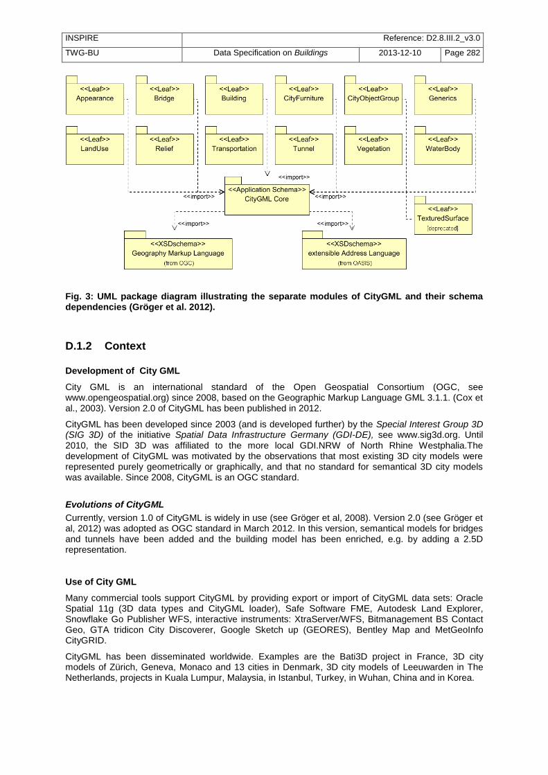
INSPIRE Reference: D2.8.III.2_v3.0
TWG-BU Data Specification on Buildings 2013-12-10 Page 282
Fig. 3: UML package diagram illustrating the separate modules of CityGML and their schema dependencies (Gröger et al. 2012).
D.1.2 Context
Development of City GML
City GML is an international standard of the Open Geospatial Consortium (OGC, see www.opengeospatial.org) since 2008, based on the Geographic Markup Language GML 3.1.1. (Cox et al., 2003). Version 2.0 of CityGML has been published in 2012.
CityGML has been developed since 2003 (and is developed further) by the Special Interest Group 3D (SIG 3D) of the initiative Spatial Data Infrastructure Germany (GDI-DE), see www.sig3d.org. Until 2010, the SID 3D was affiliated to the more local GDI.NRW of North Rhine Westphalia.The development of CityGML was motivated by the observations that most existing 3D city models were represented purely geometrically or graphically, and that no standard for semantical 3D city models was available. Since 2008, CityGML is an OGC standard.
Evolutions of CityGML
Currently, version 1.0 of CityGML is widely in use (see Gröger et al, 2008). Version 2.0 (see Gröger et al, 2012) was adopted as OGC standard in March 2012. In this version, semantical models for bridges and tunnels have been added and the building model has been enriched, e.g. by adding a 2.5D representation.
Use of City GML
Many commercial tools support CityGML by providing export or import of CityGML data sets: Oracle Spatial 11g (3D data types and CityGML loader), Safe Software FME, Autodesk Land Explorer, Snowflake Go Publisher WFS, interactive instruments: XtraServer/WFS, Bitmanagement BS Contact Geo, GTA tridicon City Discoverer, Google Sketch up (GEORES), Bentley Map and MetGeoInfo CityGRID.
CityGML has been disseminated worldwide. Examples are the Bati3D project in France, 3D city models of Zürich, Geneva, Monaco and 13 cities in Denmark, 3D city models of Leeuwarden in The Netherlands, projects in Kuala Lumpur, Malaysia, in Istanbul, Turkey, in Wuhan, China and in Korea.

INSPIRE Reference: D2.8.III.2_v3.0
TWG-BU Data Specification on Buildings 2013-12-10 Page 283
For more details on CityGML see Gröger et al. (2012), Gröger & Plümer (2012) or Kolbe et al. (2008). The next two sections focus on the two aspects which are most relevant for the TWG BU model: the building and the appearance model of CityGML.
D.2 Building Model The building model is the most important component of CityGML. It enables the representation of buildings and its parts (buildings parts, walls, roofs, windows, doors, rooms, balconies, ...) with regard to geometry as well as to semantics (feature types and properties). In this chapter, the Building model of City GML version 2.0 is introduced.
The geometry model that is employed to represent buildings (as well as to represent other features in CityGML) is based on the well-known Boundary Representation (BRep) (Mäntylä, 1988), which represents volume objects like buildings by three-dimensional solids. The extent of a solid is defined by its bounding surfaces, which delimit the solids without overlaps and without gaps (water tightness). In CityGML, all solids are bounded by planar polygons. Solids representing the geometries of a simple building with a gabled roof and a garage are depicted in Fig. 4. In CityGML, the geometry model (as well as the optional topology model) of GML 3.1, which is based on the standard ISO 19107 ‗Spatial Schema‘ (Herring, 2001), is used.
Fig. 4: Example of a Boundary Representation model consisting of two solids. The left solid is bounded by seven rectangles and the right one by six.
The restriction to planar surfaces is due to the restrictions of many tools or spatial data bases which can not deal with non-linear surfaces such as cylinder or spheric surfaces. In Fig. 5, a roof with a chimney and a dormer is depicted which is represented by a composite surface consisting of planar surfaces (total of 16 surfaces, 5 for the dormer and 5 for the chimney). In general, all shapes (including spherical or cylindes shapes) can be approximated by planar surfaces with an arbitrary small error. The smaller the error is, the smaller the surfaces are. Often triangulations are used for this purpose.
Fig. 5: Representation of a roof and its structures by planar surfaces.
Each feature that is defined in CityGML (buildings, building parts, rooms, wall surfaces, roof surfaces, doors, windows, etc.) has common attributes. These attributes are a creation and a destruction date as well as an external reference pointing to the identifier of the object in another information system, typically in the system the object initially was obtained from (e.g., in the German cadastre system ALKIS, in the German topographic information system ATKIS, or in the OS MasterMap
®). This
reference facilitates updates of CityGML features and supports the retrieval of additional information, e.g. of the owner of a building from a cadastral system. Furthermore, all CityObjects inherit a name, a

INSPIRE Reference: D2.8.III.2_v3.0
TWG-BU Data Specification on Buildings 2013-12-10 Page 284
description and metadata according to ISO 19115 (International Organization for Standardization, ISO TC 211, 2003) (lineage, accuracy, topological consistency, …) from corresponding GML classes. Fig. 5 shows the UML diagram of the core module which defines the class _CityObject.
+creationDate : xs::date [0..1]
+terminationDate : xs::date [0..1]
+relativeToTerrain : RelativeToTerrainType [0..1]
+relativeToWater : RelativeToWaterType [0..1]
<<Feature>>
_CityObject
+informationSystem : xs::anyURI [0..1]
<<DataType>>
ExternalReference
<<Feature>>
CityModel
+name : gml::CodeType [0..*]
<<Feature>>
gml::_Feature
+name : xs::string [1]
+uri : xs::anyURI [1]
<<Union>>
ExternalObjectReference
<<Feature>>
gml::_FeatureCollection <<Feature>>
Address
<<DataType>>
xAL::AddressDetails
<<Geometry>>
gml::MultiPoint
+mimeType : gml::CodeType
+transformationMatrix : TransformationMatrix4x4Type
+libraryObject : xs::anyURI
<<Object>>
ImplicitGeometry
<<Geometry>>
gml::_Geometry
<<Geometry>>
gml::Point
+name : xs::string[1]
+codeSpace : xs::anyURI[0..1]
<<DataType>>
gml::CodeType
+entirelyAboveTerrain
+substantiallyAboveTerrain
+substantiallyAboveAndBelowTerrain
+substantiallyBelowTerrain
+entirelyBelowTerrain
<<Enumeration>>
RelativeToTerrainType
+entirelyAboveWaterSurface
+substantiallyAboveWaterSurface
+substantiallyAboveAndBelowWaterSurface
+substantiallyBelowWaterSurface
+entirelyBelowWaterSurface
+temporarilyAboveAndBelowWaterSurface
<<Enumeration>>
RelativeToWaterType
+gml::doubleList [16]
<<PrimitiveType>>
TransformationMatrix4x4Type
*
*
cityObjectMember
1*
0..1*
*1
externalReference
0..1*
1
1
externalObject
11
*
*
generalizesTo
referencePoint
relativeGMLGeometry
xalAddress
multiPoint
Visual Paradigm for UML Standard Edition(Technical University Berlin)
Fig. 6: Properties of the base class _CityObject which are inherited by all features in CityGML (Gröger et al. 2012)
Buildings as well as all features in CityGML are represented in different levels of detail. Five consecutive Levels of Detail (LoD) are defined, where features become more detailed with increasing LoD regarding both their geometry and semantic differentiation. CityGML features as well as data sets can - but do not have to - contain multiple representations (and geometries) for each object in different LoD simultaneously. This enables the analysis and visualisation of the same object with regard to different degrees of resolution. LoDs are required to reflect independent data collection processes with differing application requirements. Furthermore, the classification into LoDs facilitates interoperability, since preferably features with the same LoD can be integrated. In the following, the LoDs of CityGML – LoD0 to LoD4 – are introduced. Fig. 6 provides examples for those LoDs.
In all LoDs, buildings are represented by the class Building, the attributes of which are inherited from the base class _AbstractBuilding. The attributes are a classification of the building (attribute class: public building, ...), the function (dwelling, office building, ...) and the usage in the case the actual usage differs from the intended function. The other attributes represent the year of construction/demolition, the roof type (given as an enumeration of the main types flat, monopitch, gabled, ...), the actual measured height of the building and the numbers and actual heights of the stories above and below ground. The address of the building is given by the reference to an address object (using the OASIS standard for addresses).
A building can consist of building parts, The distinction into BuildingParts accommodates the fact that components of a building differ with regard to geometry (different heights, for example) or attributes (YearOfConstruction, RoofType, …). Buildings and BuildingParts potentially have the same spatial and non spatial properties, since both are sub classes of _AbstractBuilding. Both must be consistent: If parts are present, the building geometry is represented for the parts only. The attribute values of a part apply only to that part, whereas attribute values of a building refer to all parts. Fig. 7 shows an example for a building consisting of two parts.

INSPIRE Reference: D2.8.III.2_v3.0
TWG-BU Data Specification on Buildings 2013-12-10 Page 285
Building model in LoD1 to LoD4. In LoD0 (not shown on the figure), only the topmost (or bottommost) rectangle of the LoD1 box is represented (image: KIT Karlsruhe)
Examples of a building that consists of two parts (left) and of a building that consists of one part (right)
D.2.1 Level of Detail 0 (LoD0)
In LOD0, a building is represended by horizontal 3D surfaces (2.5D). These surfaces are either at foot print level (relation lod0FootPrint) or at eaves height level (lod0RoofEgde). The UML diagram for LoD0 is given in Fig. 9.

INSPIRE Reference: D2.8.III.2_v3.0
TWG-BU Data Specification on Buildings 2013-12-10 Page 286
class Building
AbstractCityObject
«feature»
core::AbstractSite
«feature»
_AbstractBuilding
+ class: BuildingClass [0..1]
+ function: BuildingFunction [0..*]
+ lod0FootPrint: GM_MultiSurface [0..1]
+ lod0RoofEdge: GM_MultiSurface [0..1]
+ measuredHeight: Length [0..1]
+ roofType: RoofType [0..1]
+ storeyHeightsAboveGround: MeasureList [0..1]
+ storeyHeightsBelowGround: MeasureList [0..1]
+ storeysAboveGround: int [0..1]
+ storeysBelowGround: int [0..1]
+ usage: BuildingUsage [0..*]
+ yearOfConstruction: Year [0..1]
+ yearOfDemolition: Year [0..1]
«feature»
Building
«feature»
BuildingPart
«feature»
core::Address
+ multiPoint: GM_MultiPoint [0..1]
+ xalAddress: xAl:AddressDetails
0..*
+address 0..*
0..*
+consistsOfBuildingPart
0..*
Fig. 7: UML diagram of CityGML's building model: LoD017
D.2.2 Level of Detail 1 (LoD1)
The coarsest volumetric Level of Detail 1 represents buildings as blocks model, i.e. prismatic buildings with flat roofs (c.f. Fig. 6a). The UML diagram for this LoD is given in Fig. 10.
The geometry of LoD1 is represented by a solid (association lod1Solid), which is specified by the language GML as Boundary Representation (c.f. Fig. 4). The solid geometry covers the case where the geometry is completely bounded by surfaces. Alternatively, a MultiSurface geometry (association lod1MultiSurface) allows for building geometries that are not ‗water tight‘, e.g. a geometry without ground surface. Such models occur frequently in practice and should not be excluded. The terrain intersection curve, which is available in each LoD, explicitly represents the line where the building touches the surface of the terrain. That concept facilitates the smooth integration of the building into the terrain.
17
Note that for clarity reasons, the geometry in the UML diagrams for LoD0 – LoD4 is represended by attributes. In the specification document, UML classes and relations are used instead. Both representations are equivalent in these cases.

INSPIRE Reference: D2.8.III.2_v3.0
TWG-BU Data Specification on Buildings 2013-12-10 Page 287
class Building
AbstractCityObject
«feature»
core::AbstractSite
«feature»
_AbstractBuilding
+ class: BuildingClass [0..1]
+ function: BuildingFunction [0..*]
+ lod0FootPrint: GM_MultiSurface [0..1]
+ lod0RoofEdge: GM_MultiSurface [0..1]
+ lod1MultiSurface: GM_MultiSurface [0..1]
+ lod1Solid: GM_Solid [0..1]
+ lod1TerrainIntersection: GM_MultiCurve [0..1]
+ measuredHeight: Length [0..1]
+ roofType: RoofType [0..1]
+ storeyHeightsAboveGround: MeasureList [0..1]
+ storeyHeightsBelowGround: MeasureList [0..1]
+ storeysAboveGround: int [0..1]
+ storeysBelowGround: int [0..1]
+ usage: BuildingUsage [0..*]
+ yearOfConstruction: Year [0..1]
+ yearOfDemolition: Year [0..1]
«feature»
Building
«feature»
BuildingPart
«feature»
core::Address
+ multiPoint: GM_MultiPoint [0..1]
+ xalAddress: xAl:AddressDetails
0..*
+address 0..*
0..*
+consistsOfBuildingPart
0..*
Fig. 8: UML diagram of CityGML's building model: LoD1
D.2.3 Level of Detail 2 (LoD2)
Geometrically, a building in LoD2 provides the prototypic, i.e. generalized, roof shape, optionally including roof overhangs. The walls are represented geometrically by vertical surfaces, as in Lod1. Semantically, a LoD2 building has thematically differentiated surfaces particularly for the roof and the walls. The UML diagram for this LoD is depicted in Fig. 11. The semantic aspects of the classes Building, BuildingPart and _AbstractBuilding are identical to LoD1. The geometry is represented again either as a Solid or as a MultiSurface, which both are more detailed. The Lod2 geometry is distinguished from the LoD1 geometry by using different association names (lod2Solid, lod2MultiSurface, lod2TerrainIntersection). Note that LoD1 and LoD2 (as well as LoD3 and 4) are not used in a mutually exclusive way: a single building can simultaneously be represented in more than one LoD. Such a multiple representation is enabled by providing distinct names for geometry associations for each LoD.

INSPIRE Reference: D2.8.III.2_v3.0
TWG-BU Data Specification on Buildings 2013-12-10 Page 288
class Building
AbstractCityObject
«feature»
core::AbstractSite
«feature»
_AbstractBuilding
+ class: BuildingClass [0..1]
+ function: BuildingFunction [0..*]
+ lod0FootPrint: GM_MultiSurface [0..1]
+ lod0RoofEdge: GM_MultiSurface [0..1]
+ lod1MultiSurface: GM_MultiSurface [0..1]
+ lod1Solid: GM_Solid [0..1]
+ lod1TerrainIntersection: GM_MultiCurve [0..1]
+ lod2MultiCurve: GM_MultiCurve [0..1]
+ lod2MultiSurface: GM_MultiSurface [0..1]
+ lod2Solid: GM_Solid [0..1]
+ lod2TerrainIntersection: GM_MultiCurve [0..1]
+ measuredHeight: Length [0..1]
+ roofType: RoofType [0..1]
+ storeyHeightsAboveGround: MeasureList [0..1]
+ storeyHeightsBelowGround: MeasureList [0..1]
+ storeysAboveGround: int [0..1]
+ storeysBelowGround: int [0..1]
+ usage: BuildingUsage [0..*]
+ yearOfConstruction: Year [0..1]
+ yearOfDemolition: Year [0..1]
«feature»
Building«feature»
BuildingPart
«feature»
core::Address
+ multiPoint: GM_MultiPoint [0..1]
+ xalAddress: xAl:AddressDetails
AbstractCityObject
«feature»
BoundarySurface
+ lod2MultiSurface: GM_MultiSurface [0..1]
«feature»
ClosureSurface
AbstractCityObject
«feature»
BuildingInstallation
+ class: BuildingInstallationClass [0..1]
+ function: BuildingInstallationFunction [0..*]
+ lod2Geometry: GM_Object [0..1]
+ lod2ImplicitRepresentation: core:ImplicitGeometry [0..1]
+ usage: BuildingInstallationUsage [0..*]
«feature»
RoofSurface
«feature»
WallSurface
«feature»
GroundSurface
«feature»
OuterFloorSurface
«feature»
OuterCeilingSurface
+boundedBy 0..*
0..*
+outerBuildingInstallation 0..*
0..*
+boundedBy 0..*
0..*
+address 0..*
0..*
+consistsOfBuildingPart
0..*
Fig. 9: UML diagram of CityGML's building model: LoD2
In LoD2 boundary surfaces can be represented not only on a geometrical level (as part of a solid geometry), but on a semantical level as _BoundarySurface features. Such a feature can be a RoofSurface, a WallSurface, a GroundSurface, a ClosureSurface, an OuterCeilingSurface and anOuterFloorSurface
18. In order to avoid duplicated, redundant geometries, the geometry of a thematic
Boundary Surface must be shared with the corresponding solid geometry of the building. Fig. 12 illustrates this concept.
18
In LoD4, FloorSurface, InteriorWallSurface, and CeilingSurface are provided in addition.

INSPIRE Reference: D2.8.III.2_v3.0
TWG-BU Data Specification on Buildings 2013-12-10 Page 289
In LoD2 BuildingInstallations are added in addition, which represent small extensions like balconies, chimneys or outer stairs semantically.
Fig. 10: Sharing of geometries: The right surface of the building (depicted hatched) is part of a solid geometry as well as part of the WallSurface geometry
D.2.4 Level of Detail 3 (LoD3)
LoD3 is the most detailed level for the outermost shape of objects (see Fig. 1). This level denotes architectural models with detailed facade and roof structures such as balconies, bays, projections, dormers and chimneys. These objects are represented gemetrically as well as semantically. High-resolution textures can be mapped onto these structures. An example for a LoD3 building is given in Fig. 6c and the corresponding UML diagram in Fig. 13.
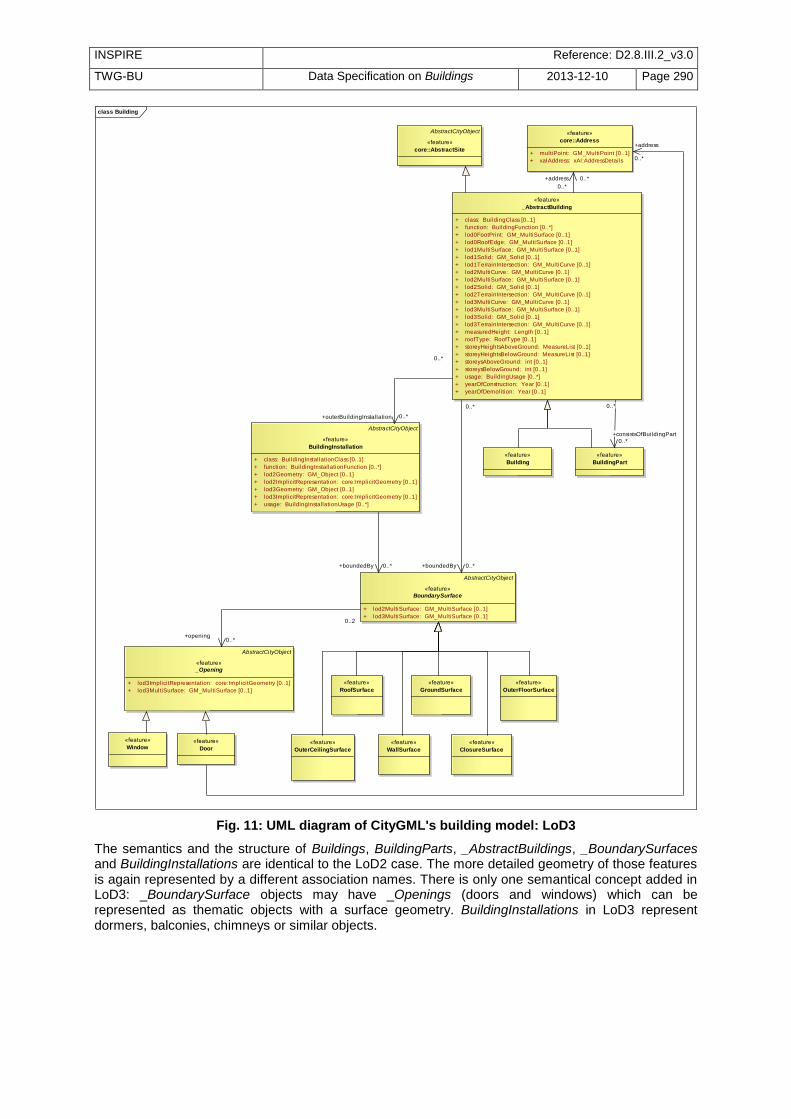
INSPIRE Reference: D2.8.III.2_v3.0
TWG-BU Data Specification on Buildings 2013-12-10 Page 290
class Building
AbstractCityObject
«feature»
core::AbstractSite
«feature»
_AbstractBuilding
+ class: BuildingClass [0..1]
+ function: BuildingFunction [0..*]
+ lod0FootPrint: GM_MultiSurface [0..1]
+ lod0RoofEdge: GM_MultiSurface [0..1]
+ lod1MultiSurface: GM_MultiSurface [0..1]
+ lod1Solid: GM_Solid [0..1]
+ lod1TerrainIntersection: GM_MultiCurve [0..1]
+ lod2MultiCurve: GM_MultiCurve [0..1]
+ lod2MultiSurface: GM_MultiSurface [0..1]
+ lod2Solid: GM_Solid [0..1]
+ lod2TerrainIntersection: GM_MultiCurve [0..1]
+ lod3MultiCurve: GM_MultiCurve [0..1]
+ lod3MultiSurface: GM_MultiSurface [0..1]
+ lod3Solid: GM_Solid [0..1]
+ lod3TerrainIntersection: GM_MultiCurve [0..1]
+ measuredHeight: Length [0..1]
+ roofType: RoofType [0..1]
+ storeyHeightsAboveGround: MeasureList [0..1]
+ storeyHeightsBelowGround: MeasureList [0..1]
+ storeysAboveGround: int [0..1]
+ storeysBelowGround: int [0..1]
+ usage: BuildingUsage [0..*]
+ yearOfConstruction: Year [0..1]
+ yearOfDemolition: Year [0..1]
«feature»
Building
«feature»
BuildingPart
«feature»
core::Address
+ multiPoint: GM_MultiPoint [0..1]
+ xalAddress: xAl:AddressDetails
AbstractCityObject
«feature»
BoundarySurface
+ lod2MultiSurface: GM_MultiSurface [0..1]
+ lod3MultiSurface: GM_MultiSurface [0..1]
«feature»
ClosureSurface
AbstractCityObject
«feature»
BuildingInstallation
+ class: BuildingInstallationClass [0..1]
+ function: BuildingInstallationFunction [0..*]
+ lod2Geometry: GM_Object [0..1]
+ lod2ImplicitRepresentation: core:ImplicitGeometry [0..1]
+ lod3Geometry: GM_Object [0..1]
+ lod3ImplicitRepresentation: core:ImplicitGeometry [0..1]
+ usage: BuildingInstallationUsage [0..*]
AbstractCityObject
«feature»
_Opening
+ lod3ImplicitRepresentation: core:ImplicitGeometry [0..1]
+ lod3MultiSurface: GM_MultiSurface [0..1]
«feature»
Window«feature»
Door
«feature»
RoofSurface
«feature»
WallSurface
«feature»
GroundSurface
«feature»
OuterFloorSurface
«feature»
OuterCeilingSurface
0..*
+consistsOfBuildingPart
0..*
0..*
+address 0..*
0..*
+boundedBy 0..*
0..*
+outerBuildingInstallation 0..*
+boundedBy 0..*
0..2
+opening0..*
+address
0..*
Fig. 11: UML diagram of CityGML's building model: LoD3
The semantics and the structure of Buildings, BuildingParts, _AbstractBuildings, _BoundarySurfaces and BuildingInstallations are identical to the LoD2 case. The more detailed geometry of those features is again represented by a different association names. There is only one semantical concept added in LoD3: _BoundarySurface objects may have _Openings (doors and windows) which can be represented as thematic objects with a surface geometry. BuildingInstallations in LoD3 represent dormers, balconies, chimneys or similar objects.

INSPIRE Reference: D2.8.III.2_v3.0
TWG-BU Data Specification on Buildings 2013-12-10 Page 291
D.2.5 Level of Detail 4 (LoD4)
LoD4 adds detailed interior structures such as rooms, (immovable) interior installations and (movable) building furniture to LoD3 (see Fig. 6d). With respect to the outermost shape of a building, LoD3 and LoD4 are identical. Fig. 14 depicts the UML diagram for LoD4.
class Building
AbstractCityObject
«feature»
core::AbstractSite
«feature»
_AbstractBuilding
+ class: BuildingClass [0..1]
+ function: BuildingFunction [0..*]
+ lod0FootPrint: GM_MultiSurface [0..1]
+ lod0RoofEdge: GM_MultiSurface [0..1]
+ lod1MultiSurface: GM_MultiSurface [0..1]
+ lod1Solid: GM_Solid [0..1]
+ lod1TerrainIntersection: GM_MultiCurve [0..1]
+ lod2MultiCurve: GM_MultiCurve [0..1]
+ lod2MultiSurface: GM_MultiSurface [0..1]
+ lod2Solid: GM_Solid [0..1]
+ lod2TerrainIntersection: GM_MultiCurve [0..1]
+ lod3MultiCurve: GM_MultiCurve [0..1]
+ lod3MultiSurface: GM_MultiSurface [0..1]
+ lod3Solid: GM_Solid [0..1]
+ lod3TerrainIntersection: GM_MultiCurve [0..1]
+ lod4MultiCurve: GM_MultiCurve [0..1]
+ lod4MultiSurface: GM_Surface [0..1]
+ lod4Solid: GM_Solid [0..1]
+ lod4TerrainIntersection: GM_MultiCurve [0..1]
+ measuredHeight: Length [0..1]
+ roofType: RoofType [0..1]
+ storeyHeightsAboveGround: MeasureList [0..1]
+ storeyHeightsBelowGround: MeasureList [0..1]
+ storeysAboveGround: int [0..1]
+ storeysBelowGround: int [0..1]
+ usage: BuildingUsage [0..*]
+ yearOfConstruction: Year [0..1]
+ yearOfDemolition: Year [0..1]
«feature»
Building
«feature»
BuildingPart
«feature»
core::Address
+ multiPoint: GM_MultiPoint [0..1]
+ xalAddress: xAl:AddressDetails
AbstractCityObject
«feature»
BoundarySurface
+ lod2MultiSurface: GM_MultiSurface [0..1]
+ lod3MultiSurface: GM_MultiSurface [0..1]
+ lod4MultiSurface: GM_MultiSurface [0..1]
«feature»
ClosureSurface
AbstractCityObject
«feature»
BuildingInstallation
+ class: BuildingInstallationClass [0..1]
+ function: BuildingInstallationFunction [0..*]
+ lod2Geometry: GM_Object [0..1]
+ lod2ImplicitRepresentation: core:ImplicitGeometry [0..1]
+ lod3Geometry: GM_Object [0..1]
+ lod3ImplicitRepresentation: core:ImplicitGeometry [0..1]
+ lod4Geometry: GM_Object [0..1]
+ lod4ImplicitRepresentation: core:ImplicitGeometry [0..1]
+ usage: BuildingInstallationUsage [0..*]
AbstractCityObject
«feature»
IntBuildingInstallation
+ class: IntBuildingInstallationClass [0..1]
+ function: IntBuildingInstallationFunction [0..*]
+ lod4Geometry: GM_Object [0..1]
+ lod4ImplicitGeometry: core:ImplicitGeometry [0..1]
+ usage: IntBuildingInstallationUsage [0..*]
AbstractCityObject
«feature»
BuildingFurniture
+ class: BuildingFurnitureClass [0..1]
+ function: BuildingFurnitureFunction [0..*]
+ lod4Geometry: GM_Object [0..1]
+ lod4ImplicitRepresentation: core:ImplicitGeometry [0..1]
+ usage: BuildingFurnitureUsage [0..*]
AbstractCityObject
«feature»
Room
+ class: RoomClass [0..1]
+ function: RoomFunction [0..*]
+ lod4MultiSurface: GM_MultiSurface [0..1]
+ lod4Solid: GM_Solid [0..1]
+ usage: RoomUsage [0..*]
AbstractCityObject
«feature»
_Opening
+ lod3ImplicitRepresentation: core:ImplicitGeometry [0..1]
+ lod3MultiSurface: GM_MultiSurface [0..1]
+ lod4ImplicitRepresentation: core:ImplicitGeometry [0..1]
+ lod4MultiSurface: GM_MultiSurface [0..1]
«feature»
Window«feature»
Door
«feature»
RoofSurface
«feature»
WallSurface
«feature»
GroundSurface
«feature»
CeilingSurface
«feature»
InteriorWallSurface
«feature»
FloorSurface
«feature»
OuterFloorSurface
«feature»
OuterCeilingSurface
+roomInstallation 0..1
0..*
+consistsOfBuildingPart
0..*
0..*
+address 0..*
0..*
+boundedBy 0..*
0..*
+outerBuildingInstallation 0..*
+boundedBy 0..*
+boundedBy 0..*
+interiorRoom
0..*
+interiorFurniture0..*
+boundedBy
0..*
0..2
+opening0..*
+address
0..*
+interiorBuildingInstallation
0..*
Fig. 12: UML diagram of CityGML's building model: LoD4
D.3 Appearance Model In addition to spatial and semantical properties, CityGML features have appearances – observable properties of the feature‘s surface. Appearances are not limited to visual data (textures showing the visual nature of a facade) but represent arbitrary categories called themes such as infrared radiation,
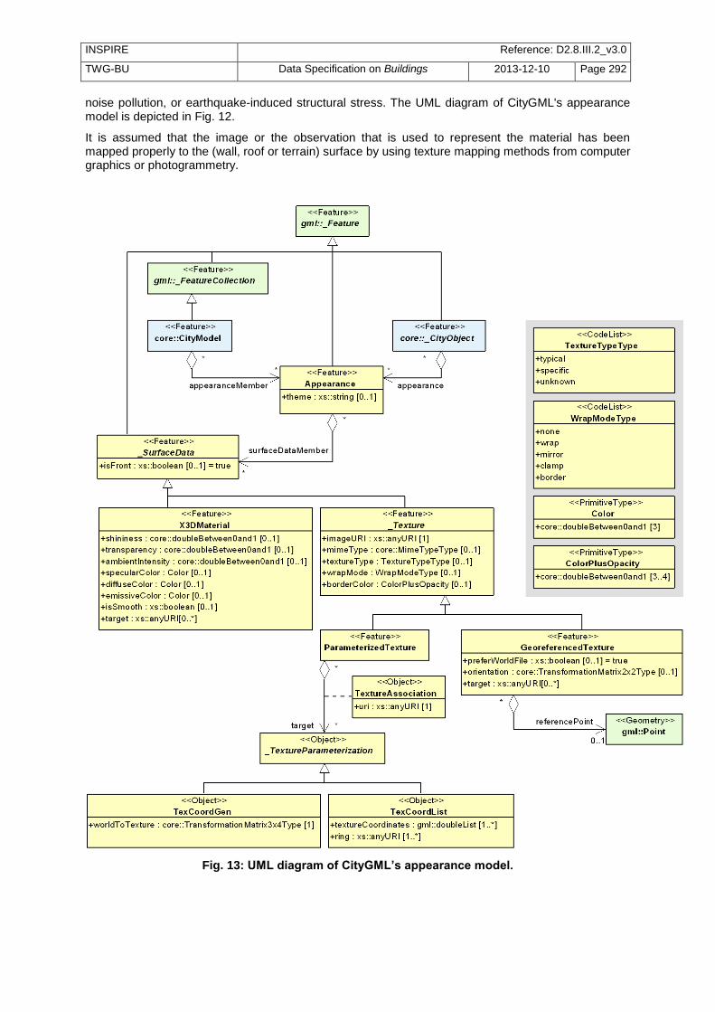
INSPIRE Reference: D2.8.III.2_v3.0
TWG-BU Data Specification on Buildings 2013-12-10 Page 292
noise pollution, or earthquake-induced structural stress. The UML diagram of CityGML's appearance model is depicted in Fig. 12.
It is assumed that the image or the observation that is used to represent the material has been mapped properly to the (wall, roof or terrain) surface by using texture mapping methods from computer graphics or photogrammetry.
Fig. 13: UML diagram of CityGML’s appearance model.

INSPIRE Reference: D2.8.III.2_v3.0
TWG-BU Data Specification on Buildings 2013-12-10 Page 293
An Appearance object collects surface data either for individual features or the whole city model in any LoD. Surface data is represented by objects of class _SurfaceData. The relation between surface data and surface geometry (e.g., the geometry of a wall of a building) is expressed by an URI (Uniform Resource Identifier) link from a _SurfaceData object to an object of type gml:AbstractSurfaceType or type gml:MultiSurface. A surface property being constant over the whore surface is modeled as material (class X3DMaterial in the UML diagram). A surface property, which depends on the location within the surface, is modeled as texture. A texture can either be a GeoreferencedTexture or a ParametrizedTexture. The class GeoreferencedTexture describes a texture that uses a planimetric projection. Alternatively, a concept similar to a reference by a world file (e.g. an ESRI world file) can be used. For Parametrized Textures, the mapping from 2D image space to 3D space is achieved either by providing texture coordinates or by applying a 3x4 transformation matrix specified by class TexCoordGen. This matrix defines a linear transformation from a spatial location in homogeneous coordinates to texture space.
Texture coordinates for a surface geometry object are specified using class TexCoordList as a texture parameterization object in the texture‘s target property. Each exterior and interior Ring composing the boundary of the target surface geometry object requires its own set of texture coordinates. Fig. 16 illustrates this concept. A TexCoordList contains as many textureCoordinate elements as the target surface geometry object contains gml:LinearRings. The content of a texture coordinate list is an
ordered list of double values where each two values defines a Tts, texture coordinate pair with s
denoting the horizontal and t the vertical texture axis. The list contains one pair per ring point with the pairs‘ order corresponding to the ring points‘ order.
Fig. 14: Positioning of textures using texture coordinates: Example
D.4 Integration of CityGML into the INSPIRE BU model
D.4.1 Commonalities between INSPIRE BU model and City GML
CityGML has strongly influenced the development of the INSPIRE BU model, both for 2D and for 3D profiles.
o The philosophy of base model defining semantical objects, attributes and relations which are required by most applications has been adopted by INSPIRE BU (as core profiles)
o The concept of External Reference to enable link to more domain-specific information systems or to ensure consistency between 2D and 3D representations of buildings has also been reused by TWG BU.
o The design pattern of Building – BuildingPart aggregation is also included in all the INSPIRE applications schemas
o Many attributes (e.g. RoofType, YearOfConstruction) have been included in INSPIRE BU profiles
Moreover, many use cases that were considered by the INSPIRE BU require a three-dimensional representation of buildings. Examples are noise emission simulation and mapping, solar radiation computation or the design of an infrastructure project. To allow for that, the building representation in LoD1 - LoD4 of CityGML has been added to the INSPIRE BU model as core 3D profile, whereas the

INSPIRE Reference: D2.8.III.2_v3.0
TWG-BU Data Specification on Buildings 2013-12-10 Page 294
whole content of LoD1 - LoD4 (including the features attached to buildings, such as boundaries, openings, rooms, …) are the base of the extended3D profile. INSPIRE BU model is based on City GML v2.0.
D.4.2 Differences between INSPIRE BU model and City GML
TWG BU has introduced the following changes to City GML:
City GML has been adapted for INSPIRE: o Example 1: the attributes regarding the classification of buildings that are loosely
harmonised in City GML (declared as string or code list from German Cadastre given as examples) have been modified/restructured to fit better with the user requirements collected by INSPIRE TWG BU.
o Example 2: to ensure cross-theme consistency, the attributes that are common to all INSPIRE themes (identifier, temporal attributes in data set) have received the name and definition supplied by the INSPIRE Generic Conceptual Model rather than the ones supplied by CityGML
CityGML has been simplified for INSPIRE o Example 1: in CityGML, the aggregation between Building and BuildingPart is
recursive (a part can have parts), whereas in INSPIRE, a part can not have parts (in the CityGML UML diagram, the aggregation starts at AbstractBuilding and is inherited by both Buildings and parts, whereas in INSPIRE, the aggregation starts at Buildings).
o Example 2: the model for appearance has been greatly simplified; only the modelling of Parameterized Texture has been kept (because being the only one relevant to model the natural appearance of a building whereas CityGML enables to model also the effect of physical phenomena, such as infrared radiation or noise pollution)
INSPIRE TWG BU has enriched the content of CityGML o Example 1: some feature types (BuildingUnit) and many attributes (e. g.
numberOfDwellings, ConditionOfConstruction) have been added to INSPIRE BU model to fulfil the user requirements related to environmental policies, that is the scope of INSPIRE. Typicaly, City GML is about topographic data wheras INSPIRE BU model also includes some official data.
- Example 2: in INSPIRE BU model, the geometry is defined as a data type including the geometry itself and some metadata to document it (accuracy, geometry reference) whereas in City GML, the geometry is just provided by geometic primitives, such as GM_Object or GM_MultiSurface
- Example 3: in the extended2D/extended3D profiles, the scope of the CityGML model has been extended to include constructions that are not considered as buildings like monuments or antennas.
D.4.3 Mapping between CityGML and INSPIRE BU model
The following table shows the possible mapping from CityGML data to INSPIRE model for feature type Building. The mapping would be quite similar for feature type BuildingPart.

INSPIRE Reference: D2.8.III.2_v3.0
TWG-BU Data Specification on Buildings 2013-12-10 Page 295
City GML (Building) TWG BU model (Building)
Core attributes (inherited) From BuildingBase::AbstractConstruction
name inspireId
creationDate name
terminationDate beginLifespanVersion
ExternalReference endLifespanVersion
Association to Address externalReference
Building attributes dateOfConstruction
geometry dateOfDemolition
class dateOfRenovation
function heightAboveGround
usage elevation
yearOfConstruction conditionOfConstruction
yearOfDemolition From BuildingBase::AbstractBuilding
storeysAboveGround buildingNature
storeyHeightsAboveGround19
currentUse
storeysBelowGround numberOfDwellings
storeyHeightsBelowGround20
numberOfBuildingUnits
aggregation into Parts numberOfFloorsAboveGround
aggregation into Parts
From buildings2D::AbstractBuilding
geometry2D
From extended2D::AbstractBuilding
association to Address
association to Cadastral Parcel
address
document
numberOfFloorsBelowground
heightBelowGround
materialOfRoof
materialOfStructure
materialOfFacade
officialArea
officialValue
roofType
energyPerformance
heatingSystem
heatingSource
floorDescription
floorDistribution
connectionToWater
connectionToSewage
connectionToGas
connectionToElectricity
connectionToWater
NOTE: attributes coloured in green are those coming from Core profiles References
19
In CityGML, the heights of each storey above ground are represented separately as elements of an array storeyHeightsAboveGround. In INSPIRE, the total height above ground is represented. 20
In CityGML, the heights of each storey below ground are represented separately as elements of an array storeyHeightsBelowGround. In INSPIRE, the total height below ground is represented.

INSPIRE Reference: D2.8.III.2_v3.0
TWG-BU Data Specification on Buildings 2013-12-10 Page 296
Cox, S., Lake, R., Portele, C., Whiteside, A., 2003. Geography Markup Language GML 3.1. OGC Doc.
No. 03-105r1. Czerwinski, A., Sandmann, S., Stöcker-Meier, E., Plümer, L., 2007. Sustainable SDI for EU noise
mapping in NRW – best practice for INSPIRE. International Journal for Spatial Data Infrastructure Research 2 (1), 90–111.
Gröger, G., Kolbe, T.H., Nagel, C., Häfele, K.-H., 2012. OpenGIS City Geography Markup Language (CityGML) Encoding Standard. Version 2.0.0., Open Geospatial Consortium, OGC Doc. No. 12-019.
Gröger, G., Kolbe, T.H., Czerwinski, A., Nagel, C., 2008. OpenGIS City Geography Markup Language (CityGML) Encoding Standard. Version 1.0.0., Open Geospatial Consortium, OGC Doc. No. 08-007r1.
Gröger, G., Plümer, L., 2012. CityGML - Interoperable semantic 3D City Models. ISPRS Journal of Photogrammetry and Remote Sensing 71 (2012):12-33, DOI http://dx.doi.org/10.1016/j.isprsjprs.2012.04.004.
Herring, J., 2001. The OpenGIS Abstract Specification, Topic 1: Feature Geometry (ISO 19107 Spatial Schema). Open Geospatial Consortium, OGC Document Number 01-101, Version 5.
International Organization for Standardization, ISO TC 211, 2003. Geographic information - Metadata (ISO 19115:2003(E)).
International Organization for Standardization, ISO TC 211, 2005. 19109:2005 Geographic information – Rules for application schema (19109:2005(E)).
Kolbe, T.H., Gröger, G., Plümer, L., 2008. CityGML - 3D City Models for Emergency Response. In: Zlatanova, S., Li, J. (Eds.), Geospatial information technology for emergency response. Taylor & Francis, London, pp. 257–274.
Mäntylä, M., 1988. An Introduction to Solid Modeling. Principles of Computer Science. Computer Science Press.
Gröger, G., Kutzner, T., Kolbe, T.H.: A CityGML based encoding for the INSPIRE Data Specification on Buildings, INSPIRE Conference 2013, Florence, Italy, June 2013. URL: http://inspire.jrc.ec.europa.eu/events/conferences/inspire_2013/schedule/submissions/241.pdf Presentation: http://inspire.jrc.ec.europa.eu/events/conferences/inspire_2013/pdfs/26-06-2013_ROOM-3_09.00%20-%2010.30_92-Tatjana%20Kutzner_Tatjana-Kutzner.pdf
van den Brink, L., Stoter, J., Zlatanova S. (Eds.): Modeling an application domain extension of CityGML in UML, OGC Discussion Paper, No. 12-066, Open Geospatial Consortium, 2012. URL: https://portal.opengeospatial.org/files/?artifact_id=49000

INSPIRE Reference: D2.8.III.2_v3.0
TWG-BU Data Specification on Buildings 2013-12-10 Page 297
Annex E (informative)
Template for additional information
Chosen profile Explain shortly which profile the data set has implemented among the ones proposed by INSPIRE
- core 2D profile - extended 2D profile (whole profile or part of it) - core 3D profile - extended 3D profile (whole profile or part of it)
Population of spatial objects, attributes and associations In the column ―Populated‖, tick (X) the populated elements. The feature type or property should be ticked if it is populated, at least for some objects. Feature types and attributes related to core profiles are shown in grey in the following table. INSPIRE element Populated INSPIRE element Populated
Building BuildingPart
geometry2D geometry2D
geometry3DLoD1 geometry3DLoD1
geometry3DLoD2 geometry3DLoD2
geometry3DLoD3 geometry3DLoD3
geometry3DLoD4 geometry3DLoD4
inspireId inspireId
elevation elevation
conditionOfConstruction conditionOfConstruction
dateOfConstruction dateOfConstruction
dateOfRenovation dateOfRenovation
dateOfDemolition dateOfDemolition
externalReference externalReference
heightAboveGround heightAboveGround
name name
beginLifespanVersion beginLifespanVersion
endLifespanVersion endLifespanVersion
currentUse currentUse
numberOfBuildingUnits numberOfBuildingUnits
numberOfFloorsAboveGround numberOfFloorsAboveGround
BuildingNature BuildingNature
numberOfDwellings numberOfDwellings
Aggregation with BuildingPart Aggregation with BuildingPart
officialArea officialArea
officialValue officialValue
heightBelowGround heightBelowGround
numberOfFloorsBelowGround numberOfFloorsBelowGround
floorDistribution floorDistribution
floorDescription floorDescription
materialOfStructure materialOfStructure
materialOfRoof materialOfRoof
materialOfFacade materialOfFacade
roofType roofType
energyPerformance energyPerformance

INSPIRE Reference: D2.8.III.2_v3.0
TWG-BU Data Specification on Buildings 2013-12-10 Page 298
heatingSource heatingSource
heatingSystem heatingSystem
connectionToElectricity connectionToElectricity
connectionToGas connectionToGas
connectionToSewage connectionToSewage
connectionToWater connectionToWater
association with installations association with installations
association with building units association with building units
association with cadastral parcels association with cadastral parcels
association with address association with address
OtherConstruction Installation
geometry2D geometry2D
geometry3D geometry3D
inspireId inspireId
elevation elevation
conditionOfConstruction conditionOfConstruction
dateOfConstruction dateOfConstruction
dateOfRenovation dateOfRenovation
dateOfDemolition dateOfDemolition
heightAboveGround heightAboveGround
externalReference externalReference
name name
beginLifespanVersion beginLifespanVersion
endLifespanVersion endLifespanVersion
otherConstructionNature installationNature
BuildingUnit
externalReference
inspireID
geometry2D
geometry3D
beginLifespanVersion
endLifespanVersion
currentUse
officialArea
officialValue
energyPerformance
heatingSource
heatingSystem
connectionToElectricity
connectionToGas
connectionToSewage
connectionToWater
association with cadastral parcels
association with address
ClosureSurface GroundSurface
geometry3D geometry3D
inspireId inspireId
beginLifespanVersion beginLifespanVersion
endLifespanVersion endLifespanVersion
OuterFloorSurface OuterCeilingSurface
geometry3D geometry3D
inspireId inspireId
beginLifespanVersion beginLifespanVersion
endLifespanVersion endLifespanVersion
RoofSurface WallSurface
geometry3D geometry3D
inspireId inspireId

INSPIRE Reference: D2.8.III.2_v3.0
TWG-BU Data Specification on Buildings 2013-12-10 Page 299
beginLifespanVersion beginLifespanVersion
endLifespanVersion endLifespanVersion
materialOfRoof materialOfWall
Door Window
geometry3D geometry3D
inspireId inspireId
beginLifespanVersion beginLifespanVersion
endLifespanVersion endLifespanVersion
Room InteriorInstallation
geometry3D geometry3D
inspireId inspireId
beginLifespanVersion beginLifespanVersion
endLifespanVersion endLifespanVersion
roomNature internalInstallationNature
ParameterizedTexture
imageURI
mimeType
textureType
Selection criteria: Building (and BuildingPart, if any) Explain which buildings are captured for INSPIRE and which are not. For instance, is there a minimum size for data capture? Are there some categories of buildings that are not captured? If the definition is significantly different from the one used by INSPIRE, provide it. OtherConstruction (if any) Explain which OtherConstructions are captured and which are not. BuildingUnit (if any) Explain what is considered as a BuildinUnit Installation (if any) Explain which Installations are captured and which are not. Data capture process – data capture rules For 2D profiles, explain if data is captured as 2D or as 2,5D data. For 3D data, explain briefly which levels of details are used; if textures are provided, give explanations about them (for which buildings, which kind of textures, …). Provide the main rules to capture buildings and constructions, with focus on the aspects that are not already included in UML model Examples:
- What is considered as a building? What is considered as part of building (if any)? - in case of a generalised capture of building, which are the main generalisation rules? - how are specific buildings (without roof) captured? - are buildings cut by cadastral boundaries? - may two buildings overlap? In which cases?
Temporal aspects
Old data Explain if the building data set published for INSPIRE contains only current version or also depreciated features. If it is the case, explain which (e.g. from when?)

INSPIRE Reference: D2.8.III.2_v3.0
TWG-BU Data Specification on Buildings 2013-12-10 Page 300
If necessary, give more detailed explanations about temporal attributes (e.g. how demolished buildings are considered) Life-cycle rules: Give the life-cycle rules of buildings and constructions (i.e. in which cases an object will get a new inspire identifier and in which case an object will just be considered as a new version of same object) Mapping with INSPIRE values Attribute currentUse The classification of buildings in source data is likely different from the one proposed by INSPIRE. Explain the mappings that are not obvious, that are only approximations (e.g. what occurs in case of mix use?) Other attributes Any mapping that is not obvious correspondence should be documented. Generic mechanisms ExternalReference Explain which information systems may be connected to buildings (and building units) and what kind of information may be found. For instance: - cadastral register: information about owner(s), evaluation of building - dwelling register: information about type of dwelling (number of rooms) and comfort elements (toilets, type of heating …) - database of buildings receiving public : type of building, capacity, … Document Explain which kinds of document are generally available. For instance: - sketch of each floor for all buildings - construction permits for buildings after 1980 - photos of façade for noticeable buildings Extendable code lists Some code lists in theme BU are extendable. In case a producer adds some possible values to one or several of these code lists, these values must be documented (by definition and possibly description)
Any other useful information Add in this paragraph any other information you consider helpful for users (and not already included in the INSPIRE specification or in previous paragraphs of this template or in other metadata elements).

INSPIRE Reference: D2.8.III.2_v3.0
TWG-BU Data Specification on Buildings 2013-12-10 Page 301
Annex F (informative)
Extension of INSPIRE Buildings model
F.1 Introduction - Context As a general rule, the INSPIRE application schemas may be extended by data providers, under conditions given in the Generic Conceptual Model, i.e. only if the extension does not break any of the INSPIRE requirements. This data specification offers two extended profiles, one for 2D (or 2,5D) data and one for 3D data. These extended profiles may and even should be used by data providers, willing to provide more information than the information included in the normative core profiles. For instance, a data provider who wants to replace its current products by INSPIRE themes will have to supply all its data through an INSPIRE conformant model. The INSPIRE extended profiles may be applied as a whole but also aim to be a ―reservoir‖ of proposals for extensions of core INSPIRE profile, i.e. only a selection of proposed feature types and attributes may be added. The two methods are described in next chapter. Extended 2D profile includes many concepts coming mainly from cadastral/official information systems. Typically, it is expected that most cadastral/official organisation will adopt (at least partly) the feature types and attributes proposed in the extended profile, taking into account the possible restrictions/adaptations due to national regulations (e.g. privacy issues). It concerns for instance building units, official area, official value, address, connections to networks. For extended profiles both 2D and 3D include also some detailed topographic data (e.g. height and number of floors for the underground part of building, roof type, materials, installations) and even walls, roof, openings, rooms, textures in case of 3D profile; the main purpose is to encourage data producers to capture this information in future. Of course, it is also expected that the possibilities of extension will be used soon, but likely by very few data providers (as few data is available until now). INSPIRE data specifications will evolve in future; of course, the concepts that are now in the extended profile might be candidates for inclusion in the normative profile, during the future updates of INSPIRE specifications.
The other extension mechanism relates to the code lists; some INSPIRE code lists are extendable, either ―narrower‖ or ―any‖. Examples of such extensions are provided in last chapter of this annex.
F.2 Extension of INSPIRE UML application schema
F.2.1 Using whole schema
Data providers may use the extended application schemas provided in this document, either extended 2D or extended 3D profiles. These INSPIRE application schemas are formal extensions of the core profiles, i.e. they inherit from the application schemas of core profile. The inheritance mechanism ensures that all requirements from core profile have been imported into the extended profile, and so, that the extension has been done respecting the rules given in the Generic Conceptual Model. Consequently, a data provider supplying its data according to an INSPIRE Buildings extended profile will be automatically conformant to the Implementing Rule related to theme Buildings.

INSPIRE Reference: D2.8.III.2_v3.0
TWG-BU Data Specification on Buildings 2013-12-10 Page 302
Advantage: the schema is used as it is; so, no modelling effort is required from data provider. Drawback: data provider and data users have to handle whole extended schema; this may add complexity for data transformation (e.g. dealing with unpopulated features and attributes) and for daily use of data (manipulating a big model). This option is quite suitable if data provider has a significant ratio of the additional concepts offered by the INSPIRE extended profiles.
F.2.2 Using extract of extended schema
Data providers may define their own extension, by importing (and so inheriting) one of the core profiles and by adding attributes or even features based on the concepts given in the INSPIRE extended profiles, in order to include in this home-made extension only the data they have. EXAMPLE: A provider of cadastral data wants to supply only additional attributes address and official area as additional elements of core 2D profile. This may be done as shown in figure below.

INSPIRE Reference: D2.8.III.2_v3.0
TWG-BU Data Specification on Buildings 2013-12-10 Page 303
class Prov iderDefined
Buildings Provider Defined Extension
Buildings2D
BuildingsBase
«featureType»
BuildingsBase::AbstractConstruction
+ inspireId: Identifier
«voidable, l ifeCycleInfo»
+ beginLifespanVersion: DateTime
+ endLifespanVersion: DateTime [0..1]
«voidable»
+ conditionOfConstruction: ConditionOfConstructionValue
+ dateOfConstruction: DateOfEvent [0..1]
+ dateOfDemolition: DateOfEvent [0..1]
+ dateOfRenovation: DateOfEvent [0..1]
+ elevation: Elevation [0..*]
+ externalReference: ExternalReference [0..*]
+ heightAboveGround: HeightAboveGround [0..*]
+ name: GeographicalName [0..*]
«featureType»
BuildingsBase::AbstractBuilding
«voidable»
+ buildingNature: BuildingNatureValue [0..*]
+ currentUse: CurrentUse [0..*]
+ numberOfBuildingUnits: Integer [0..1]
+ numberOfDwellings: Integer [0..1]
+ numberOfFloorsAboveGround: Integer [0..1]
«featureType»
BuildingsBase::
Building
«featureType»
BuildingsBase::
BuildingPart
«featureType»
Buildings2D::Building
+ geometry2D: BuildingGeometry2D
«featureType»
Buildings2D::BuildingPart
+ geometry2D: BuildingGeometry2D [1..*]
Building
+ address: AddressRepresentation [0..*]
+ officialArea: OfficialArea [0..*]
BuildingPart
+ address: AddressRepresentation [0..*]
+ officialArea: OfficialArea [0..*]
+parts
«voidable»0..*
Data producer extension importing <Buildings 2D> and using INSPIRE
<Buildings Extended2D> concepts.
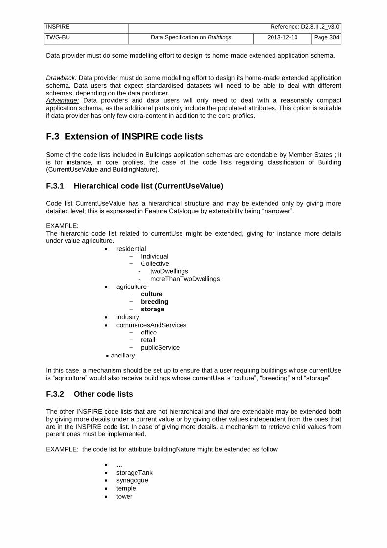
INSPIRE Reference: D2.8.III.2_v3.0
TWG-BU Data Specification on Buildings 2013-12-10 Page 304
Data provider must do some modelling effort to design its home-made extended application schema. Drawback: Data provider must do some modelling effort to design its home-made extended application schema. Data users that expect standardised datasets will need to be able to deal with different schemas, depending on the data producer. Advantage: Data providers and data users will only need to deal with a reasonably compact application schema, as the additional parts only include the populated attributes. This option is suitable if data provider has only few extra-content in addition to the core profiles.
F.3 Extension of INSPIRE code lists Some of the code lists included in Buildings application schemas are extendable by Member States ; it is for instance, in core profiles, the case of the code lists regarding classification of Building (CurrentUseValue and BuildingNature).
F.3.1 Hierarchical code list (CurrentUseValue)
Code list CurrentUseValue has a hierarchical structure and may be extended only by giving more detailed level; this is expressed in Feature Catalogue by extensibility being ―narrower‖. EXAMPLE: The hierarchic code list related to currentUse might be extended, giving for instance more details under value agriculture.
residential − Individual − Collective
- twoDwellings - moreThanTwoDwellings
agriculture − culture − breeding − storage
industry
commercesAndServices − office − retail − publicService
ancillary In this case, a mechanism should be set up to ensure that a user requiring buildings whose currentUse is ―agriculture‖ would also receive buildings whose currentUse is ―culture‖, ―breeding‖ and ―storage‖.
F.3.2 Other code lists
The other INSPIRE code lists that are not hierarchical and that are extendable may be extended both by giving more details under a current value or by giving other values independent from the ones that are in the INSPIRE code list. In case of giving more details, a mechanism to retrieve child values from parent ones must be implemented. EXAMPLE: the code list for attribute buildingNature might be extended as follow
…
storageTank
synagogue
temple
tower

INSPIRE Reference: D2.8.III.2_v3.0
TWG-BU Data Specification on Buildings 2013-12-10 Page 305
controlTower
lookoutTower
clockTower
coolingTower
communicationTower
windmill
windTurbine
windmill
kiosk
phoneBooth
busShelter
…
F.3.3 Code lists in extended schemas
Note that code lists in extended schemas have obligation set to ―Technical Guidelines‖. As the extended application schema itself, the code lists are not normative but only recommendations. Consequently; most of them have also extensibility set to ―any‖; however, some code lists may have extensibility set to ―none‖ in case extending the code list would break the consistency in the list of possible values. This is typically the case of the code list related to official area and based on the CLGE standard: the code list is not extendable at all but the model offers the possibility to use another code list.

INSPIRE Reference: D2.8.III.2_v3.0
TWG-BU Data Specification on Buildings 2013-12-10 Page 306
Annex G (informative)
Acknowledgements
G.1 As-is analysis
Person Organisation Product Country
WG on CadastreINSPIREd
EuroGeographics – Permanent Committee on Cadastre
Cadastre data Europe
Julius Ernst Federal office of Surveying and Metrology (BEV).
Digital Cadastral Map (DKM)
Austria
Frederic Mortier General Administration of Patrimonial Documentation
CadMap - CaBu Belgium
Frederic Mortier NGI (Nationaal Geografisch Insituut) IGN (Institut Géographique National)
ITGI VRef Belgium
Frederic Mortier NGI (Nationaal Geografisch Insituut) IGN (Institut Géographique National)
ITGI VGen Belgium
Frederic Mortier NGI (Nationaal Geografisch Insituut) IGN (Institut Géographique National)
TOP250v-GIS Belgium
Geoffroy Detry Comité Technique de Cartographie de la Région wallonne (SPW)
PICC Belgium
Frederic Mortier GIS-Flanders (AGIV) GRB Belgium
Frederic Mortier Brussels Region Informatics Center (BRIC)
UrbIS Adm, UrbIS Top and UrbIS Map
Belgium
Karen Skeljo FOT (municipalities) and KMS
FOT + BDR Denmark
Hanno Kuus Estonian Land Board Estonian National Topographic Database
Estonia
Mare Braun Ministry of Economic Affairs and Communications
Register of Construction Works
Estonia
Laurent Breton Institut Géographique National
BD UNI , BD TOPO France
Grégoire Maillet Institut Géographique National
Bâti 3D France
Gerhard Gröger Working Committee of the Surveying Authorities of the States of the Federal Republic of Germany (AdV) –
AAA project (ALKIS-AFIS-ATKIS), unified model for cadastre (ALKIS) and topography (ATKIS)
Germany

INSPIRE Reference: D2.8.III.2_v3.0
TWG-BU Data Specification on Buildings 2013-12-10 Page 307
Zsuzsanna Ferencz
Institute of Geodesy, Cartography and Remote Sensing
Land Administration-cadastral map
Hungary
Bronislovas Mikuta State Enterprise Centre of Registers (SECR)
Real property cadastre DB Real property cadastral map
Lithuania
Frank Kooij Kadaster (Netherlands' Cadastre, Land Registry, and Mapping Agency)
National Registers of Addresses and Buildings (BAG)
Netherlands
Lars Mardal Morten Borrebaek
Geovekst (Norwegian Mapping Authorithy in cooperation with other public authorithies)
FKB-Bygning (Base Data Building
Norway
Ewa Wysocka GUGiK (Head Office of Geodesy and Cartography)
EGiB (Land and Building Cadastre) – cadastral data TOPO/TBD (Topographical database) – topographical data
Poland
Adriana Padureanu Romania-National Agency for Cadastre and Land Registration(NACLR)
E-terra (cadastre and land book) INTRAVILAN (census)
Romania
Adriana Padureanu Minister of Regional Development and Tourism
SISDIEBU (estate domain and urban data base)
Romania
Martina Behulakovia Geodesy, Cartography and Cadastre Authority of the Slovak Republic
CSKN (Centrálny systém katastra nehnuteľností) and ZB GIS (Topographic database GIS)
Slovakia
Tomas Petek Surveying and Mapping Authority of the Republic of Slovenia
Building cadastre database
Slovenia
Amalia Velasco
Spanish Directorate General for Cadastre, - Ministry of Economy and Finance
Spanish Cadastre Spain
Eddie Bergström National Land Survey Grunddata Byggnad (Base Data Building)
Sweden
Marc Nicodet Swiss cadastral surveying
Federal Directorate of Cadastral Surveying
Switzerland
Simon Barlow Ordnance Survey
MasterMap Topography Layer
Great Britain
Simon Barlow Local Government Information House
National Land and Property Gazetteer
England and Wales
G.2 User requirements
Person Organisation Result
EEA (European Environmental Agency)
Joint meeting with TWG BU

INSPIRE Reference: D2.8.III.2_v3.0
TWG-BU Data Specification on Buildings 2013-12-10 Page 308
Julián Álvarez Gallego
ADIF (Administrador de Infraestructuras Ferroviarias). Dirección de Patrimonio y Urbanismo.
Check-list about railway building management
Giorgio Arduino Regione Piemonte, DG ENV
Check-list about air quality monitoring and assessment
Olivier Banaszak Direction of Urban Studies and Prospective – Le Havre City
Check-list about urban studies –Le Havre
Dolors Barrot CENG (Specialised Commission for Geographic Standards)
Check-list about Urban Topographic database - Spain
Jose I. Barredo Floods Action, IES, JRC Check-list about implementation of Flood Directive in Europe
François Belanger INVS (Institute of Health Monitoring) - France
Check-list about Health studies - France
Laurent Breton Vector database Service - Institut Géographique National - France
Check-list about accurate land cover - France
Bert Boterbergh Agency for Roads and Traffic, Flemish Government - Belgium
Check-list about ADA Road database - Belgium
Eric Cajoly Marketing Unit - Institut Géographique National - France
Check-list about Territoire 3D - France
Aline Clozel Community of Agglomeration Avignon - France
Check-list about Habitat – Avignon- France
Marie-Christine Combes
Direction of Urbanism – Paris municipality - France
Check-list about urbanism in Paris - France
Antony Cooper Commission on Geospatial Data Standards – International Cartographic Association
Contribution to check-list crowd-sourcing for INSPIRE
Jerôme Cortinovis Air Normand - France Check-list about air quality – Normandy - France
A. Czerwinski IGG, University of Bonn, coordinator of Noise emission simulation and mapping implementation in North Rhine Westphalia
Check-list about Implementation of EU Environmental Noise Directive in North Rhine Westphalia
Matthijs Danes Alterra Wageningen UR
Check-list about effects of city on temperature and air quality
Tom De Groeve Joint Research Centre of the European Commission
Check-list about risk analysis and loss estimation for wind storms
Laurent Delgado Consulting Unit - Institut Géographique National - France
Check-lists : - Urban Units (for Statistical
Institute) - Efficiency of antenna (for
telecommunication company) - Population grid for television
coverage (for (National Council of Audiovisual).
Jean-Luc Déniel SHOM (Hydrographic and Oceanograpic Service of Navy)
Check-list about safety of marine navigation
Alexandra Delgado Jiménez
Observatory on Sustainability in Spain (OSE)/Studies of location of new services
Check-list about architecture and urban planning - Spain
Yannick Depret Marketing Unit - Institut Géographique National - France
List of possible use cases - France
Ekkehard Petri Statistical Office of the European Communities - DG Eurostat -Unit D.2 - Geographical Information LUXEMBOURG
Check-list about GISCO data base
M Foote Willis Research Network Check list about insurance
Jean-Marie Grand Lyon - France Check-list about Grand Lyon

INSPIRE Reference: D2.8.III.2_v3.0
TWG-BU Data Specification on Buildings 2013-12-10 Page 309
Fournillier
Julien Gaffuri Joint Research Centre (JRC) - European Commission Contact point for TWG BU
Check-list about research projects - urban analysis - simulation of urban
development Check-list about Waste Water Treatment Directive
Jean-François Girres COGIT (Research Laboratory) – Institut Géographique National - France
Check-list about OpenStreetMap
Bruno Gourgand CERTU (Centre for Studies on Transport, Network, Urbanism and Public Constructions) - France
List of possible use cases + contact points - France
Silvio Granzin
Federal environment agency Austria, department for Contaminated Sites, Vienna
Check-list about Register of potentially contaminated sites, Austria
Cédric Grenet Community of municipalities Seine Valley – Caux region - France
Check-list about 3D models
G. Gröger Project leader of project to implement tool for estimation of solar potential of roof surfaces, at IGG, University of Bonn
Check-list about Sun Exposure Calculation for Roof Surfaces
Anders Grönlund Lantmäteriet - Sweden Check-list about flood forecasting
Mark Halliwell UK Hydrographic Office Check-list about marine charts
Javier Hervás
Land Management and Natural Hazards Unit Institute for Environment and Sustainability Joint Research Centre (JRC) - European Commission
Check-list about landslide risk
Jan Hjelmager Commission on Geospatial Data Standards – International Cartographic Association
Contribution to check-list crowd-sourcing for INSPIRE
Hanne Moller Jensen
Region Zealand - Denmark Check list about earth pollution.
Hooft Elise Flemish Heritage Institute (Vlaams Instituut voor het Onroerend Erfgoed)
Check-list about inventory of architectural Heritage in the Flemish Region
Kenneth Ibsen Agency for Spatial and Environmental Planning - Denmark
Check-list about modelling and monitoring wastewater discharge - Denmark
INSPIRE TWG Production and Industrial Facilities
INSPIRE TWG Production and Industrial Facilities
Check-list about industrial risk
Yolène Jahard Consulting Unit – Institut Géographique National - France
Check-list about valorisation of patrimony for railway company.
Frédérique Janvier SOeS - Ministry of Sustainable Development - France
Check-list about environmental statistics
Laurent Jardinier CERTU (Centre for Studies on Transport, Network, Urbanism and Public Constructions) - France
Check-list about sustainable transport - France
Steffen Kuntz
geoland2 project Check-list about Urban Atlas
Gregor Kyi Eurostat – Census unit
Check-list about census of population and dwellings
Jean-Christopher Lambert
Belgian Institute for Space Aeronomy (IASB-BIRA)
Check-list about atmospheric Research - Belgium

INSPIRE Reference: D2.8.III.2_v3.0
TWG-BU Data Specification on Buildings 2013-12-10 Page 310
Gerard Leenders Land Registry and Mapping Agency, Netherlands
Check-list about EULIS
Luc Lefebvre CNES (French Spatial Agence)
Check-list about stratospheric balloons - France
Marc Léobet MIG (Mission of Geographic Information) - France
Check-list about Risk management - France
Matthew Longman Ashfield District Council - UK
Check-list about Local Authority Refuse Collection - UK
Josefa Lopez Barragán
INE (National Statistics Institute) Check-list about Population and Housing Census - Spain
David Ludlow Centre for Research in Sustainable Planning and Environments – UK (?)
Check-list about Urban sprawl – EEA initiative
José Ramón Martinez Cordero
Subdirección General de Dominio Público Marítimo-Terrestre. Secretaría General del Mar. Ministerio de Medio Ambiente y Medio Rural y Marino.
Check-list about protection of coastal areas - Spain
Johan Mortier Elia High voltage power line management - Belgium
Susana Munoz Gas Natural Fenosa - Spain Check-list about database for gas and electricity management - Spain
Anne Nærvig-Petersen
Statistics Denmark Check-list about Housing inventory- Denmark
Ana-Maria Olteanu France Telecom Check-list about implementation of new antennas for mobile phone.
Nicolas Paparoditis MATIS (Research Laboratory on Images) - Institut Géographique National - France
Check-list about façade thermography
Simon Parkinson Smart Industry Design Team - Iberdrola-ScottishPower
Check-list about energy retail – supply
Véronique Pereira Consulting Unit - Institut Géographique National - France
Check-lists : - obstacles for air transport (for
SIA -Service of Aeronautical Information)
- easements for air transport (for STBA Technical Service of Aerial Bases)
- Noise maps (for CSTB Centre Technical Security of Buildings)
- Sun exposure (for electricity companies)
Manuela Pfeiffer State agency for agriculture, environment and rural areas of the state Schleswig-Holstein - Germany
Check-list about implementation of Flood Directive in Germany
Odile Rascol INSEE (National Statistical Institute) - France
Check-list about buildings for census
Marianne Ronsbro Region Zealand - Denmark Check list about earth pollution.
Jean-Pierre Sabatier CUB Bordeaux (Community of Agglomeration) – France
Check-list about roof thermography - France
François Salgé Ministry of Sustainable Development - France Facilitator TWG LU
Check-list about GéoPLU (France) and plan4all (Europe)
Marc Salvador Segarra
General Directorate of Department of the Interior, institutional relations and participation,
Check-lists: -security and emergency – Spain - prevention, extinction of fires and

INSPIRE Reference: D2.8.III.2_v3.0
TWG-BU Data Specification on Buildings 2013-12-10 Page 311
Generalitat de Catalunya - Spain bailouts and rescues
David Sánchez Blázquez
Programa de Impulso al Urbanismo en Red - Spain
Check-list about ―urbanismo en red‖
Per Sandqvist Lantmäteriet - Sweden Check-list about blue lights services
Jesus San Miguel JRC FOREST Action (European Forest Fire Information System – EFFIS) :
Check-list about forest fire risk
Tristan Saramon IBERDROLA RENOVABLES FRANCE.
Check-list about new wind farms
Claudia Secco Regione Piemonte Department of Environment
Check-list about noise map calculation
Markus Seifert Facilitator of INSPIRE TWG PS Check-list about protection of historic buildings
J. Steinrücken IGG, Univ. of Bonn, project leader of several bicycle and tourism route planning tools/portals - Germany
Check-list about tourism/leisure - Germany
Yvan Strubbe Flemish public transport company (VVM De Lijn)
Check-list about scheduling of public transport. (new bus stops) - Belgium
Karl-Erik Svensson National Board of Housing, Building and Planning
Check-list about Energy Performance of Building Directive (EPDB)
Fabio Taucer Joint Research Centre, ELSA Unit, IPSC, European Commission
Check-list about Seismic risk analysis and loss estimation.
Guilllaume Touya COGIT (Research Laboratory) – Institut Géographique National - France
Check-list about OpenStreetMap
Gaspar Valls Solé Office of Urbanism and economic activities. Diputació de Barcelona (Barcelona Provincial Council)- Spain
Check-lists: - location of economic activities – Spain - SITMUN project: Municipal Territorial Information System Barcelona
Miet Van Den Eeckhaut
Land Management and Natural Hazards Unit- Institute for Environment and Sustainability Joint Research Centre (JRC) - European Commission
Check-list about landslide risk
Frans van der Storm Program manager X-border-GDI (Netherlands – Germany)
Check-list about X-Border GDI applications (risk atlas, spatial planning)
Ana Velasco CartoCiudad project- (National Geographic Institute of Spain-National Center of Geographic Information CNIG).
Check-list about CartoCiudad project - Spain
Maarten Vermeyen Flemish Heritage Institute (Vlaams Instituut voor het Onroerend Erfgoed)
Check-list about inventory of architectural Heritage in the Flemish Region
François Virevialle Mapping Unit – Institut Géographique National - France
Check-list about historic and archaeological GIS in Bordeaux
Magnus Walestad Statistics Sweden Check-list about building permits as indication for economic forecasts
Scott Wilson EUROCONTROL Check-list about Air Traffic Management