inspecting foundation walls and piers - nachi. · pdf fileinspecting foundation walls and...
TRANSCRIPT
~ 1 ~
INSPECTING FOUNDATION WALLS AND PIERS
This publication is designed to help the home inspector evaluate foundation walls and piers.
Additionally, it provides insight into newer innovations pertaining to products and their
usage. This book is offered as a learning tool to augment InterNACHI’s Continuing
Education online course in preparation for successful completion of the online course and
final exam. This manual also provides a useful on-the-job reference guide for inspectors.
Authors: Ben Gromicko, Director of Online Education,
International Association of Certified Home Inspectors
and Executive Producer, NACHI.TV
Nick Gromicko, Founder, International Association of
Certified Home Inspectors
Graphics: Lisaira Vega, Director of Graphics / Architect
Editor & Layout: Kate Tarasenko / Crimea River
To order online, visit www.InspectorOutlet.com
© Copyright 2010-2013 International Association of Certified Home Inspectors
All rights reserved.

~ 2 ~
Definition of Terms………………………………………………………. 3
Masonry Walls.................................................................................. 3 (also: Masonry Cracks; Bricks & Mortar; Above-Ground Masonry Walls) Fire Damage……….….......................................................................... 11
Structural Failure…………………….................................................... 11
Innovations: Cement Admixtures...................................................... 17 (also: Innovations: Cement Substitutes)
Precast Concrete Foundation and Wall Panels................................. 24 (also: Insulating Concrete Forms)
Formwork for Ventilated Concrete Slabs........................................... 26
Innovations: Concrete Footing and Pier Forms................................ 27
Pumice-Crete...................................................................................... 29
Innovations: Concrete Aggregate Substitutes.................................. 30
Innovations: Fibrous Concrete Reinforcement................................. 32
Innovations: Autoclaved Aerated Concrete...................................... 33
Cracking in Concrete………................................................................. 34 (also: Settlement; Brick Veneer Walls)
Masonry and Concrete Adhesives....................................................... 42
Innovations: Concrete Waterproofing Systems................................. 43
Water-Resistant Polythylene Sub-Floor System………………………… 44
Foundation Drainage Panels................................................................. 45
Foundation Flood Vents…………………………………………………….. 47
Steel Foundation Systems…….……………………………………………. 48 (also: Frost-Protected Shallow Foundations (FPSFs)
Wood Foundations…...………………………………………………………. 50
ICF Walls: Wood Fiber Composite Forms……….………………………. 52
Vapor Barriers…………………………………………………………………. 53
Plastic Ductwork Systems…………..………………………………………. 55
Flashing Products…………………….………………………………………. 56
Modular Block Retaining Wall Systems..…………………………………. 60
Manufactured Housing Ground-Anchor Systems………………………. 61
(also: Disaster-Resistant Pier)
Prefabricated Storm Shelters………….……………………………………. 63
Inspecting
Foundation Walls and Piers:
TABLE of CONTENTS
~ 3 ~
DEFINITION of TERMS
Foundation walls and piers in small residential buildings are usually made of masonry
and should be inspected for cracking, deterioration, moisture penetration, and structural
adequacy.
The foundation bed may be composed of solid rock, sand, gravel, or unconsolidated sand
or clay. Rock, sand and gravel are the most reliable foundation materials. Unconsolidated
sand and clay are common in many areas of the United States, but are not as desirable for
foundations because they are subject to sliding and settling.
The footing distributes the weight of the building over a sufficient area of ground to ensure
that the foundation walls will stand properly. Footings are usually concrete; however, in the
past, wood and stone have been used. Some older houses were constructed without
footings. Although it is usually difficult to determine the condition of a footing without
excavating the foundation, a footing in a state of disrepair, or the lack of a footing, will
usually be indicated either by settlement in the foundation walls or by large cracks. These
cracks are called “Z” cracks.
The foundation walls support the weight of the structure and transfer this weight to the
footings. The foundation walls may be made of stone, brick, concrete, or concrete blocks.
The exterior should be moisture-proofed with either a coating of Portland cement mortar or
a membrane of waterproof material. The membrane may consist of plastic sheeting, or a
sandwich of standard roofing felt joined and covered with tar or asphalt. Waterproofing the
foundation and walls will prevent water from penetrating the wall material and leaving the
basement or cellar walls damp.
MASONRY
All exposed masonry should be inspected for cracking, spalling, bowing (vertical bulging),
sweeping (horizontal bulging), leaning, and mortar deterioration. Before beginning a
detailed masonry inspection, determine
which walls are load-bearing and which are
not. Usually, this can be done by
examining the beams and joists in the
building’s basement, crawlspace or attic.
Also note whether the walls are solid
masonry or masonry-cavity, non-structural
brick, or stone veneer. The overall quality
of the building’s construction, and often
that of its neighborhood, will be a good
indicator of the condition of its masonry.
A common masonry wall crack probably
caused by thermal or moisture expansion.
Active cracks can be sealed with a flexible
sealant; inactive cracks may be pointed.
~ 4 ~ There may be a substantial difference in the masonry walls in buildings built during the last
40 to 50 years compared to those constructed earlier. Walls became thinner as designers
began to more effectively exploit the compressive strength of masonry. This was done by
using higher strength masonry materials and mortars. This change came at the expense of
flexibility; as such, walls are often more brittle than their massive ancestors and, therefore,
more subject to stress-induced damage.
Testing
Two methods of testing are sometimes useful for assessing masonry.
Probe holes are drilled through the joints or masonry units with a
masonry bit and probed with a stiff wire (or, if available, a fiber optic
device) to determine a wall’s thickness and the adequacy of its
mortar. The probe holes are then patched after the investigation has
been completed.
A hammer test can be used to determine the structural soundness of
masonry units and their bond to the mortar. In a hammer test, the
masonry is tapped lightly with a hammer, and the resonance of the
sound produced is evaluated.
Two additional tests may also be useful: ASTM E518, the Standard Test Methods for Flexural
Bond Strength of Masonry; and ASTM E519, the Standard Test Method for Diagonal Tension
(Shear) in Masonry Assemblages. These test should be performed by a qualified masonry
contractor.
The brick shown above is greatly spalled as a result of excessive moisture penetration and
subsequent freezing. Although individual bricks can be replaced and the mortar pointed, the
damage cannot be repaired. If re-pointed, the new mortar should be of the same
composition as the existing.
MASONRY CRACKS
Although masonry can deform elastically over long periods of time to accommodate small
amounts of movement, large movements normally cause cracking. This is known as
masonry cracking.
Cracks may appear along the mortar joints or through the masonry units. Cracking can
result from a variety of problems:
differential settlement of foundations;
drying shrinkage (particularly in concrete block);
expansion and contraction due to ambient thermal and moisture variations;
improper support over openings, the effects of freeze-thaw cycles;
the corrosion of iron and steel wall reinforcement;
differential movement between building materials;
expansion of salts; and
the bulging or leaning of walls.
~ 5 ~
Differential Settlement Caused by Variable Soil Types
Cracks should always be evaluated to determine their cause and whether corrective action is
required. Look for signs of movement. A clean crack indicates recent movement; a dirty or
previously filled crack may be inactive. A pocket lens may be useful for such an
examination.
Correlate the width
of larger cracks to
the age of the
building. A 1/2-inch
crack in a new
building may be a
sign of rapid
settlement, but in a
building 50 years
old, it may indicate a
very slow movement
of only 1/100 of an
inch (0.25 mm) per
year. In each case,
the cause and
treatment may differ.
Testing
Crack movement can be measured with a commercially available joint movement indicator.
This device is temporarily fastened over the crack and a scribe records movement over a
period of time. Cyclical movements may take six months or more to measure, but diurnal
movements can be recorded over a few days. Hand measurements can also be made of
crack movements, but these will be less precise and require repeated field visits. All tests
should be performed by a licensed contractor.
~ 6 ~
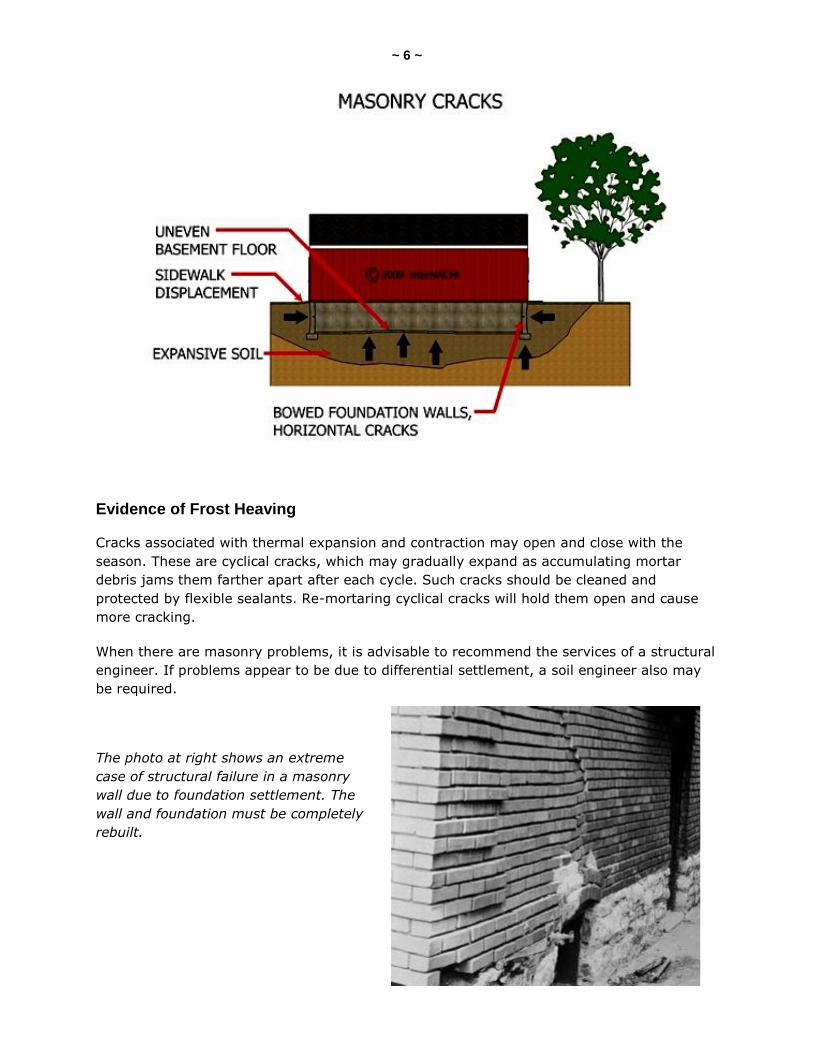
Evidence of Frost Heaving
Cracks associated with thermal expansion and contraction may open and close with the
season. These are cyclical cracks, which may gradually expand as accumulating mortar
debris jams them farther apart after each cycle. Such cracks should be cleaned and
protected by flexible sealants. Re-mortaring cyclical cracks will hold them open and cause
more cracking.
When there are masonry problems, it is advisable to recommend the services of a structural
engineer. If problems appear to be due to differential settlement, a soil engineer also may
be required.
The photo at right shows an extreme
case of structural failure in a masonry
wall due to foundation settlement. The
wall and foundation must be completely
rebuilt.
~ 7 ~
BRICKS and MORTAR
The two important qualities of mortar are its ability to bond to masonry and its internal
strength. A sign of mortar deterioration may be random cracking at the bond joint. Until
about the end of the 19th century, the standard mortar for masonry was a mixture of sand
and pure lime or lime-possolan-sand. These low-strength mortars gave masonry the ability
to absorb considerable strain. Accordingly, the tendency to crack was reduced, and when
cracks did appear in the mortar joints, they were, to a great extent, capable of chemical
reconstitution, or “self-healing.” Thus, the age of the building may be a good clue in
evaluating its mortar problems. Older mortar (or mortar of any age that uses hydrated lime)
will be softer and may require pointing, but otherwise may be responsible for a sound wall.
Most often, mortar deterioration is found in areas of excessive moisture, such as near
leaking downspouts, below windows, and at the tops of walls. In such cases, the water
should be redirected and the joints should be re-pointed. Pointing should be performed with
mortar of a composition similar to or compatible with the original mortar. The use of high-
strength mortar to point mortar of a lower strength can do serious damage to the masonry,
since the pointing can’t “flex with” or act in a similar way with the rest of the joint.
It is useful to remember that mortar acts as a drainage system to equalize hydrostatic
pressure within the masonry. Nothing should be done to reduce its porosity and thereby
block water flow to the exterior surface.
Testing
To determine the composition of existing mortar (the percentage of lime and other
materials), a sample can be removed and chemically analyzed by a testing laboratory. This
should be done by a qualified structural engineer.
The deterioration of masonry units in the form of spalling, dusting, or flaking of brick may
be due to either mechanical or chemical damage. Mechanical damage is caused by moisture
entering the brick and freezing, resulting in spalling of the brick’s outer layers. Spalling may
continue or may stop of its own accord after the outer layers that trapped the interior
moisture have broken off. Chemical damage is caused by the leaching of chemicals from the
ground into the brick, resulting in internal deterioration. External signs of such deterioration
are a dusting or flaking of the brick.
Very little can be done to correct existing mechanical and chemical damage, with the
exception of replacement of the brick. Mechanical deterioration can be slowed or stopped by
directing water away from the masonry surface and by pointing mortar joints to slow water
entry into the wall. Surface sealants (damp-proofing coatings) are rarely effective, and may
hasten deterioration by trapping the moisture and/or soluble salts that inevitably penetrate
the wall and, in turn, cause further spalling. Chemical deterioration can be slowed or
stopped by adding a damp-proof course into the brick wall just above the ground line, or by
injecting a damp-proofing material into the same area. Recommend a masonry specialist for
this type of repair.
~ 8 ~
ABOVE-GROUND MASONRY WALLS
Inspect above-ground stone, brick, and concrete-block walls for signs of the following
problems:
brick-wall cracking associated with thermal and moisture movement: Above-ground
brick walls expand in warm weather (particularly if facing south or west), and
contract in cool weather. This creates stress in the walls that may cause a variety of
cracking patterns, depending on the configuration of the wall and the number and
location of openings. Such cracks are normally cyclical and will open and close with
the season—they will grow wider in cold weather and narrower in hot weather. Look
for cracking at the corners of long walls, walls with abrupt changes in cross-section
(such as at a row of windows), walls with abrupt turns or jogs, and in transitions
from one- to two-story walls. These are the weak points that have the least capacity
for stress. Common moisture and thermal movement cracking includes:
o horizontal or diagonal cracks near the ground at piers in long walls due to
horizontal shearing stresses between the upper wall and the wall where it
enters the ground. The upper wall can thermally expand, but its movement at
ground level is moderated by earth temperatures. Such cracks extend across
the piers from one opening to the next along the line of least resistance. This
condition is normally found only in walls of substantial length.
o vertical cracks near the end walls due to thermal movement. A contracting
wall does not have the tensile strength to pull its end walls with it as it moves
inward, causing it or the end walls to crack vertically where they meet.
o vertical cracks in short offsets and setbacks caused by the thermal expansion
of the longer walls that are adjacent to them. The shorter walls are “bent” by
this thermal movement and crack vertically.
o vertical cracks near the top and ends of the facade due to the thermal
movement of the wall. This may indicate poorly bonded masonry. Cracks will
tend to follow openings upward.
o cracks around stone sills and lintels caused by the expansion of the masonry
against both ends of a tight-fitting stone piece that cannot be compressed.
Cracks associated with thermal and moisture movement often present only
cosmetic problems. After their cause has been determined, they should be
repaired with a flexible sealant, since filling such cyclic cracks with mortar will
simply cause the masonry to crack in another location. Cracks should be
examined by a structural engineer and may require the installation of
expansion joints
brick wall cracking associated with freeze-thaw cycles and corrosion. Brick walls
often exhibit distress due to the expansion of freezing water or the rusting of
embedded metals.
~ 9 ~
Such distress includes:
o cracking around sills, cornices, eaves, chimneys, parapets, and other
elements subject to water penetration, usually due to the migration of water
into the masonry. The water expands upon freezing, breaking the bond
between the mortar and the masonry, and eventually displacing the masonry
itself. The path of the water through the wall is indicated by the pattern of
deterioration.
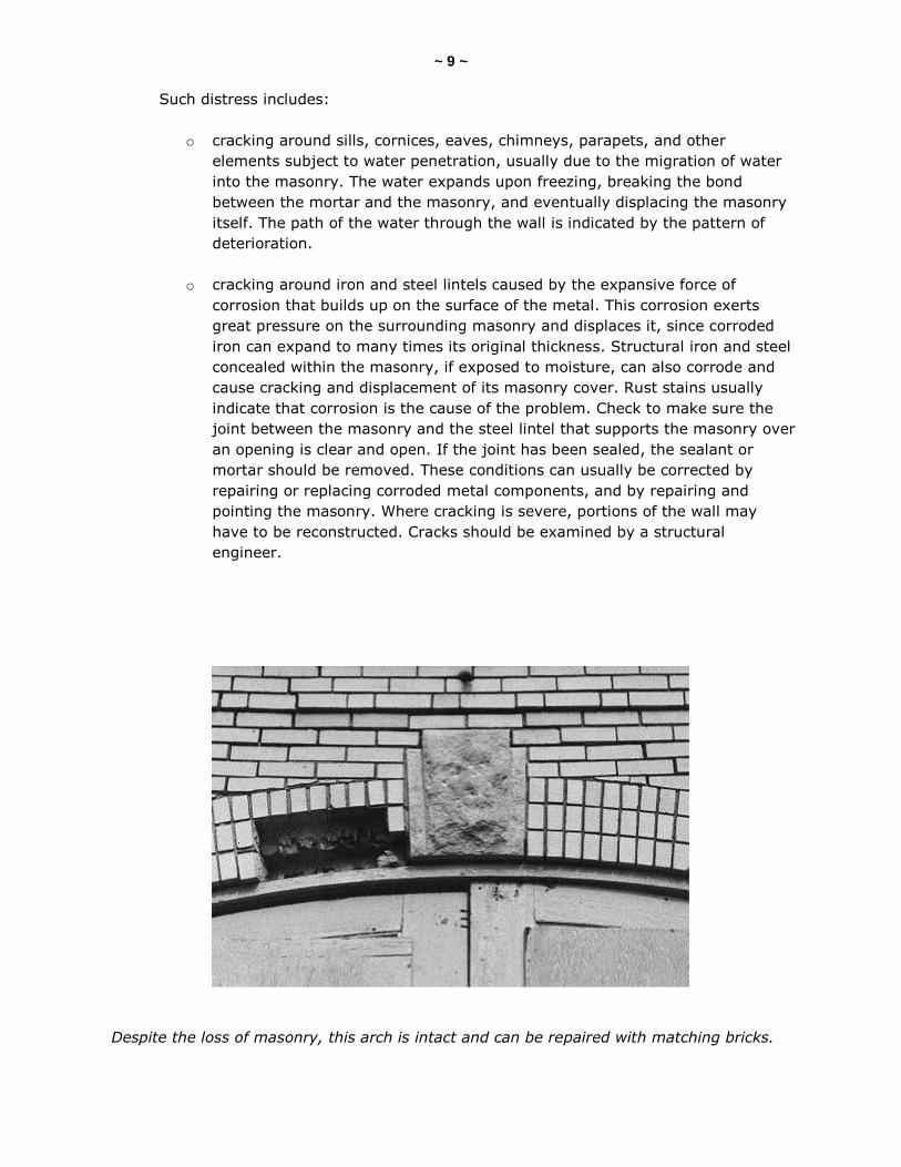
o cracking around iron and steel lintels caused by the expansive force of
corrosion that builds up on the surface of the metal. This corrosion exerts
great pressure on the surrounding masonry and displaces it, since corroded
iron can expand to many times its original thickness. Structural iron and steel
concealed within the masonry, if exposed to moisture, can also corrode and
cause cracking and displacement of its masonry cover. Rust stains usually
indicate that corrosion is the cause of the problem. Check to make sure the
joint between the masonry and the steel lintel that supports the masonry over
an opening is clear and open. If the joint has been sealed, the sealant or
mortar should be removed. These conditions can usually be corrected by
repairing or replacing corroded metal components, and by repairing and
pointing the masonry. Where cracking is severe, portions of the wall may
have to be reconstructed. Cracks should be examined by a structural
engineer.
Despite the loss of masonry, this arch is intact and can be repaired with matching bricks.
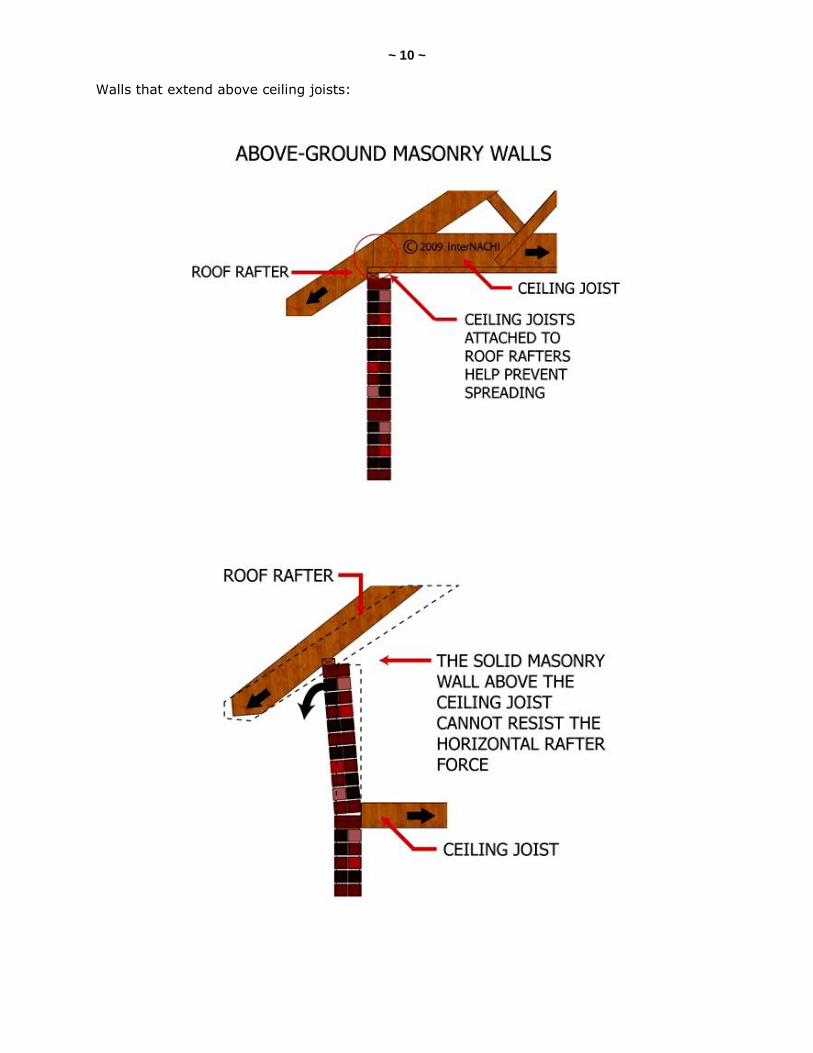
~ 10 ~ Walls that extend above ceiling joists:
~ 11 ~
FIRE DAMAGE
Fire Damage to Brick Masonry Walls
Masonry walls exposed to fire will resist damage in proportion to their thickness. Examine
the texture and color of the masonry units and probe their mortar. If they are intact and
their basic color is unchanged, they can be considered serviceable. If they undergo a color
change, recommend a qualified structural engineer for further appraisal. Hollow masonry
units can be examined by a structural engineer for internal cracking. Such units may need
replacement if seriously damaged. Masonry walls plastered on the side in direct contact with
flame may have been sufficiently protected and will have suffered few, if any, ill effects.
STRUCTURAL FAILURE
Wall Cracking or Displacement Associated with the Structural Failure of Building Elements
Problems related to the structure, aside from those caused by differential settlement or
earthquakes, are usually found over openings and (less commonly) under roof eaves and in
areas of structural overloading. Such problems include:
• cracking and displacement of masonry over openings, resulting from the deflection and
failure of the lintels and arches that span the openings. In older masonry walls with
wood lintels, cracking will occur as the wood sags and decays. Iron and steel lintels also
cause cracking as they deflect over time. Concrete and stone lintels occasionally bow
and sometimes crack.
Masonry arches of brick and stone may crack and fail when there is wall movement and
when their mortar joints deteriorate. When such lintel deflections and arch failures occur,
the masonry above may be supporting itself and will exhibit step cracks, beginning at the
edges of the opening and joining in an inverted “V” above the opening’s midpoint.
Correcting such problems usually means replacing failed components and rebuilding the
area above the opening.
Occasionally, masonry arches fail because the walls that surround them cannot provide an
adequate counter-thrust to the arch action. This sometimes happens on windows that are
too close to the corners of a wall or bay. In such cases, the masonry arch pushes the
unbraced wall outward, causing it to crack above the opening near or just above the spring
of the arch. When this occurs, the end walls must be strengthened.
• cracking or outward displacement under the eaves of a pitched roof due to a failure in
the horizontal roof ties, which results in the roof spreading outward. The lateral thrust
of the roof on the masonry wall may cause it to crack horizontally just below the eaves,
or to move outward with the roof. In this case, the roof will probably be leaking, as
well.
~ 12 ~ When this occurs, examine the roof structure carefully to ascertain whether there is a tying
failure. If so, additional horizontal ties or tension members will have to be added and, if
possible, the roof pulled back into place. The damaged masonry can then be repaired. The
weight also can be transferred to interior walls. Jacking of the ridge and rafters is
another possible solution.
• cracking due to overloading (or interior movement) is fairly uncommon, but may be
caused by a point load (often added during an alteration) which is bearing on a wall of
insufficient thickness. If the member has been concealed, such a problem will be difficult
to investigate. The addition of interior wall supports or bracing, however, may correct
the source of the problem by relieving the load.
• cracking due to ground tremors from nearby construction, heavy vehicular traffic, or
earthquakes. This cracking is roughly vertical in direction and occurs more toward the
center of the building. Buildings exhibiting such cracking should be treated on a case-by-
case basis, since serious structural damage may have taken place. Recommend a
structural engineer experienced in such matters.
Bulging Walls
Masonry walls sometimes show signs of bulging as they age. A wall itself may bulge, or the
bulge may only be in the outer withe. Bulging often takes place so slowly that the masonry
doesn’t crack and, therefore, it may go unnoticed over a long period of time. The bulging of
the whole wall is usually due to thermal or moisture expansion of the wall’s outer surface, or
due to contraction of the inner withe. This expansion is not completely reversible because,
once the wall and its associated structural components are “pushed” out of place, they can
rarely be completely “pulled” back to their original positions.
The effects of the cyclical expansion of the wall are cumulative and, after many years, the
wall will show a detectable bulge. Inside the building, separation cracks will occur on the
inside face of the wall at floors, walls and ceilings.
Bulging of only the outer masonry withe is usually due to the same gradual process of
thermal or moisture expansion; masonry debris accumulate behind the bulge and prevent
the course from returning to its original position.
In very old buildings, small wall bulges may result from the decay and collapse of an
internal wood lintel or wood-bonding course. This can cause the inner course to settle and
the outer course to bulge outward.
When wall bulges occur in solid masonry walls, the walls may be insufficiently tied to the
structure, or their mortar may have lost its bond strength. Large bulges must be tied back
to the structure; the star-shaped anchors on the exterior of masonry walls of many older
buildings are examples of such ties (check with local building ordinances on their use).
Small bulges in the outer masonry course often can be pinned to the inner course or
dismantled and rebuilt.
~ 13 ~
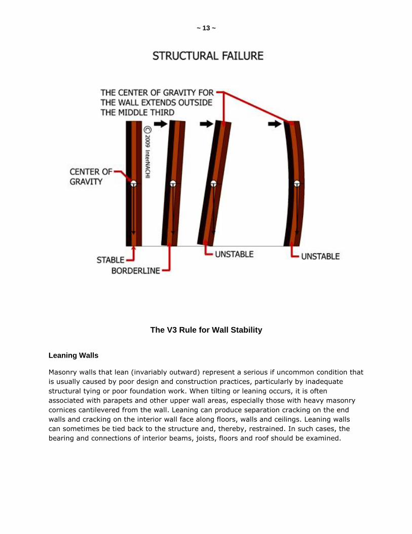
The V3 Rule for Wall Stability
Leaning Walls
Masonry walls that lean (invariably outward) represent a serious if uncommon condition that
is usually caused by poor design and construction practices, particularly by inadequate
structural tying or poor foundation work. When tilting or leaning occurs, it is often
associated with parapets and other upper wall areas, especially those with heavy masonry
cornices cantilevered from the wall. Leaning can produce separation cracking on the end
walls and cracking on the interior wall face along floors, walls and ceilings. Leaning walls
can sometimes be tied back to the structure and, thereby, restrained. In such cases, the
bearing and connections of interior beams, joists, floors and roof should be examined.

~ 14 ~
Above: a bowed brick veneer wall
When large areas or whole walls lean, rebuilding the wall (and possibly the foundation) may
be the only answer.
Testing
A wall is usually considered unsafe if it leans to such an extent that a plumb line passing
through its center of gravity does not fall inside the middle third of its base (the V3 Rule).
In such an event, recommend a structural engineer.
~ 15 ~
QUIZ 1
1. T/F: A 1/2-inch-wide crack in a 50-year old building may be a sign of rapid settlement.
True
False
2. A footing in disrepair can lead to _______ in the foundation walls.
Z-cracks
pock marks
flaking
3. Foundation walls and piers in small residential buildings are usually made of _____________.
preservative-treated wood
steel
masonry
4. T/F: Rock, sand and gravel are the most reliable foundation materials.
True
False
5. Vertical bulging in the masonry is known as _________.
sweeping
bowing
spalling
6. Horizontal bulging in the masonry is known as ____________.
sweeping
bowing
spalling
7. In a ________ test, the masonry is tapped lightly and the resonance of the sound produced is evaluated.
hammer
hacksaw
hearing (continued)
~ 16 ~ 8. Excessive moisture penetrating and subsequent freezing can lead to _________.
spleening
forking
spalling
9. T/F: Cyclical cracks should be re-mortared.
True
False
10. Masonry walls exposed to fire will resist damage in proportion to their _________.
age
height
thickness
Answer Key to Quiz 1
1. T/F: A 1/2-inch-wide crack in a 50-year old building may be a sign of rapid settlement. Answer: False
2. A footing in disrepair can lead to Z-cracks in the foundation walls.
3. Foundation walls and piers in small residential buildings are usually made of masonry.
4. T/F: Rock, sand and gravel are the most reliable foundation materials. Answer: True
5. Vertical bulging in the masonry is known as bowing.
6. Horizontal bulging in the masonry is known as sweeping.
7. In a hammer test, the masonry is tapped lightly and the resonance of the sound produced is evaluated.
8. Excessive moisture penetrating and subsequent freezing can lead to spalling.
9. T/F: Cyclical cracks should be re-mortared. Answer: False
10. Masonry walls exposed to fire will resist damage in proportion to their thickness.
~ 17 ~
INNOVATIONS: CEMENT ADMIXTURES
Admixtures are materials other than cement, aggregate and water that are added to
concrete either before or during its mixing to alter its properties, including its workability,
curing temperature range, set time, or color. Some admixtures have been in use for a very
long time, such as calcium chloride, which is used to provide a cold-weather setting
concrete. Others are more recent and represent an area of expanding possibilities for
increased performance. Not all admixtures are economical to use on a particular project.
Also, some characteristics of concrete, such as low absorption, can be achieved simply by
consistently adhering to high-quality concreting practices.
The chemistry of concrete admixtures is a complex topic requiring in-depth knowledge and
experience. A general understanding of the options available for concrete admixtures is
necessary for acquiring the right product for the job, based on climatic conditions and job
requirements.
Based on their functions, admixtures can be classified into the following five major
categories:
• retarding admixtures;
• accelerating admixtures;
• super-plasticizers;
• water-reducing admixtures; and
• air-entraining admixtures.
Among other important admixtures that do not fit into these categories are admixtures
whose functions include bonding, shrinkage reduction, damp-proofing, and coloring. The
following information provides details on the five categories of concrete admixtures.
Retarding Admixtures
Retarding admixtures slow down the hydration of cement, which lengthens its set time.
Retarders are used in hot-weather conditions in order to overcome the accelerating effects
of higher temperatures, and on large masses of concrete to lengthen setting time.
Because most retarders also act as water reducers, they are frequently called water-
reducing retarders. Per the chemical admixture classification by the ASTM, ASTM C 494
Type B is simply a retarding admixture, while Type D is both retarding and water-reducing,
resulting in concrete with greater compressive strength because of the lower water-to-
cement ratio.
Retarding admixtures consist of both organic and inorganic agents. Organic retardants
include unrefined calcium, sodium, NH4, salts of lignosulfonic acids, hydrocarboxylic acids,
and carbohydrates. Inorganic retardants include oxides of lead and zinc, phosphates,
magnesium salts, fluorates and borates.

~ 18 ~ An example of a retardant's effects on concrete properties includes lignosulfate acids and
hydroxylated carboxylic acids, which slow the initial setting time by at least an hour, and no
more than three hours, when used at 65 to 100 degrees Fahrenheit. The concrete
contractor, however, need not memorize these chemical-specific results. Given the specific
job requirements and goals, the concrete supplier should offer appropriate admixtures and
concrete mixes from which to choose.
Accelerating Admixtures
Accelerators shorten the set time of concrete, allowing a cold-weather pour, early removal
of forms, early surface finishing and, in some cases, early load application.
Proper care must be taken while choosing the type and proportion of accelerators as, under
most conditions, commonly used accelerators cause an increase in the drying shrinkage of
concrete.
Calcium chloride is a common accelerator used to accelerate the time of set and the rate of
strength-gain. It should meet the requirements of ASTM D 98. Excessive amounts of
calcium chloride in concrete mix may result in rapid stiffening, increase in drying shrinkage
and corrosion of reinforcement. In colder climates, calcium chloride should not be used as
an anti-freeze. Large amounts of calcium chloride are required to lower the freezing point of
the concrete, which may ruin the concrete.
Super-Plasticizers
Super-plasticizers, also known as plasticizers, include water-reducing admixtures. Compared
to what is commonly referred to as a "water reducer" or "mid-range water reducer," super-
plasticizers are "high-range water reducers." High-range water reducers are admixtures that
allow large water reduction or greater flowability without substantially slowing set time or
increasing air entrainment (as defined by the manufacturers, concrete suppliers and
industry standards).
Each type of super-plasticizer has defined ranges for the required quantities of concrete mix
ingredients, along with the corresponding effects. They can maintain a specific consistency
and workability at a greatly reduced amount of water. Amounts needed vary by the
particular concrete mix and type of super-plasticizer used. They can also produce a high-
strength concrete. As with most types of admixtures, super-plasticizers can affect other
concrete properties, as well. The specific effects, however, should be provided by the
manufacturer or concrete supplier.
Water-Reducing Admixtures
Water-reducing admixtures require less water to make a concrete of equal slump
or increased slump at the same water content. They can have the side effect of changing
initial set time. Water reducers are mostly used for hot-weather concrete placing, and to aid
pumping.
~ 19 ~ A water-reducer plasticizer, however, is a hygroscopic powder, which can entrain air into
the concrete mix via its effect on water's surface tension, thereby obtaining some of the
benefits of air-entrainment.
Air-Entraining Admixtures
Air-entraining agents entrain small air bubbles in the concrete. The major benefit of this is
enhanced durability in freeze-thaw cycles, which is especially important in cold climates.
While some strength can be lost with increased air in concrete, it can generally be overcome
by reducing the water-to-cement ratio via the improved workability made possible by the
air-entraining agent, or through the use of other appropriate admixtures. As always,
admixtures should only be combined in a concrete mix by a competent professional,
because some of the admixtures can interact in undesirable ways.
Bonding admixtures, including the addition of compounds and materials such as polyvinyl
chlorides and acetates, acrylics, and butadiene-styrene co-polymers, can be used to assist
in bonding new or fresh concrete with old or set concrete.
Coloring agents have become more commonly used, especially for patios and walkways.
Most are surface-applied, and often have the additional effect of surface hardening. Such
surface-applied coloring admixtures generally should not be used on air-entrained concrete.
Integrally colored concrete is also available.
Waterproofing and damp-proofing admixtures, including soaps, butyl stearate, mineral oil
and asphalt emulsions, are used to decrease the amount of water penetration into the
larger pores of concrete. "Antifreeze" admixtures are accelerators used in very high
amounts (with a corresponding high price) which achieve a very fast set time. They do not,
however, have properties to protect against freezing. In general, these are not used for
residential work.
Cement substitutes also change concrete properties, but are not generally classified as
admixtures.
Most organic chemical-type admixtures are affected by cement type and brand, water-to-
cement ratio, aggregate grading, and temperature. Damp-proofing and waterproofing
admixtures still have uncertain value and hazards. These are just two cases that point to
the learning curve required of anyone working with admixtures.
In some cases, if directions are not followed exactly, including the addition of supplemental
materials to balance the negative or undesirable side effects of an admixture, the resulting
concrete mix may be compromised. For example, retarding admixtures generally have a
possibility of rapid concrete stiffening, resulting in difficulty in placement and finishing.
Therefore, an in-depth knowledge of the potentially complex interrelated effects is required
to use a number of admixtures successfully.
~ 20 ~ This is even more critical when several parties are involved in the manufacture of the
concrete, such as the producer, the placing contractor, and the builder. The finished
concrete is a combined result of a number of individual decisions.
Choosing an appropriate admixture for a specific job should be the responsibility of an
experienced expert. Alternatives to the use of admixtures should always be considered.
The environmental impact of certain admixtures is questionable. Some super-plasticizers
may impact the environment through pollution of ground and surface waters. More research
remains to be conducted in this area.
Finally, admixtures cannot compensate for bad practice and low-quality materials.
~ 21 ~
INNOVATIONS: CEMENT SUBSTITUTES
Producing cement uses a great deal of energy, so finding a waste product that can
substitute for cement makes good environmental sense. According to the Environmental
Building News (EBN), as much greenhouse gas is created producing the Portland cement
used in the U.S. as is created operating 22 million compact cars. In addition, the U.S.
imports about 20% of the 100 million metric tons of cement it uses annually, adding to its
cost and using more energy. Burning coal to make electric power creates a great deal of
waste fly ash. A smaller amount of slag is created when producing iron in blast furnaces.
Coal fly ash, blast-furnace slag and other mineral admixtures can substitute for cement in
concrete mixes for buildings which will save energy and recycle a waste product,
thereby improving the quality of the concrete and reducing costs. Cement substitutes should
be distinguished from concrete additives, such as plasticizers and air-entrainment agents,
and from aggregate substitutes, such as ground glass or ground scrap rubber.
Types of Cement Substitutes
Fly ash is one of the byproducts of burning coal to create electric power. Two-thirds of the
55 million tons of fly ash produced in the U.S. in 1999 was sent to waste piles, with only 9
million tons used to make concrete. The carbon content of fly ash is a major concern. Class
C fly ash, most of which is produced in the West from lignite coal, contains little carbon.
However, Class F fly ash, produced primarily from anthracite and bituminous coal, contains
significant amounts of carbon. Class C and Class F materials also differ from source to
source with regard to strength, rate of strength-gain, color and weatherability. Ensuring a
consistent supply is a concern among concrete suppliers.
Slag is a byproduct of the production of both iron and steel, and ground iron slag from blast
furnaces can be used for making concrete. About 12.4 million tons of blast-furnace slag was
used in the U.S. in 1999, of which 2 million tons were used in concrete. In addition, another
1.1 million tons were imported for use by the construction industry. Because the demand for
the product is rising while the supply is falling, new grinding plants are coming online to
process imported slag. The added energy used to ship and grind the slag makes it
somewhat less energy-saving than fly ash, but far better than Portland cement.
Silica fume was once a cheap waste product, but high demand has made it a high-cost
admixture used primarily for bridges and other structures where top weathering
performance and high strength are needed. Concrete made from silica fume is expensive,
however, not only because of the material cost, but because the powdery fineness of the
fume makes it hard to handle. It is often turned into slurry before use.
As long as quality is controlled, rice hull ash is another material that can be used to replace
cement. So far, its use remains in the laboratory stage, although a consistent-quality ash
needed for concrete is available.
~ 22 ~
Slow Strength-Gain
Generally, cement substitutes work in two ways. First, they hydrate and cure like Portland
cement. Second, they are "pozzolans," providing silica that reacts with hydrated lime, an
unwanted byproduct of concrete curing. Blast-furnace slag is most like Portland cement and
least like a pozzolan. Class F fly ash is most like a pozzolan, and Class C fly ash is
somewhere in the middle. While stronger and more durable in the end, it takes more time
than Portland cement for pozzolans to gain strength. For most construction purposes, high
early strength is very desirable because it allows quicker finishing of slabs and earlier
removal of forms. Reducing the amount of water can compensate for slow strength-gain.
Researchers have made concrete in the lab from high percentages of cement substitute by
drastically reducing the water content and adding super-plasticizers to maintain the required
slump, but such mixes are not yet common and may be costly.
Mixes with 15% to 25% fly ash and somewhat higher percentages of slag can be used in
home building with only a modest slowing of strength-gain. Higher percentages can be used
in footings, where high early strength is typically not important. Precasters and concrete
masonry unit (CMU) producers can maintain precise control of the mix, and use more
admixtures. However, they require high early strength for fast reuse of forms, so precast
concrete seldom has high percentages of cement substitutes.
Air-Entrainment and Carbon Content
Some fly ash, and most of the Class F fly ash used in the East, contains high levels of
carbon, which are unburned coal particles resulting from the lower-temperature burning
(low-NOx) that improves air quality. Carbon particles absorb the soapy air-entraining
chemicals used to improve cold-weather performance, and, in this way, make the air
content unpredictable. This problem has led some Northern suppliers to substitute slag
admixture for fly ash, since slag contains no carbon. The fly ash industry is addressing this
problem by processing high-carbon fly ash to remove most of the carbon.
Concrete with mineral admixtures may require more air-entraining chemicals to ensure
freeze-thaw protection because the small particles of these minerals can fill voids in the
concrete that would otherwise be air bubbles.
Strength
Strength is improved by the substitution of some mineral admixtures for Portland cement.
Class C fly ash and slag improve strength more than Class F fly ash. In applications where
high strength is critical, such as in high-rise buildings, silica fume is the cement substitute
of choice, resulting in compressive strengths of 15,000 psi and higher.
~ 23 ~ Color
Class C fly ash results in a buff-colored concrete; Class F is a darker gray. Slag concrete is
lighter in color, with high reflectivity. During curing, slag concrete may show a blue-green
mottling, called "greening." However, the color is usually gone from the surface in a week.
Its disappearance depends on oxidation, so slag cement is not recommended for swimming
pools.
Weatherability
There are three weatherability conditions that cement substitutes help alleviate:
• permeability and chloride-induced corrosion: De-icing salts can migrate through pores in
the concrete, break down the passive protective layer around the re-steel, and cause
corrosion that leads to spalling. The pozzolanic action of cement substitutes removes
the calcium hydroxide that makes the concrete permeable and, therefore, is highly
desirable in roadways. A high percentage of fly ash is not recommended for slabs and
paving exposed to the weather because of dusting and scaling of the surface.
• alkali-silica reaction (ASR): High-silica aggregates and high-alkali cement (which is
becoming more common) can create ASR, which causes internal expansion and crazing
of concrete. Cement substitutes, especially slag, remove the alkalinity through
pozzolanic action. Class C fly ash varies in this ability, while Class F fly ash is very
effective.
• sulfate attack: Concrete made with 60% or more slag is very effective in mitigating
attack by sulfates found in some arid soils, seawater and wastewater. The pozzolanic
action of fly ash also contributes to sulfate resistance.
Although the federal government and the heavy-construction industry have used cement
substitutes for decades, residential contractors are less familiar with their use. As the fly ash
industry develops processes to remove carbon, variations in the composition of fly ash will
become less important, and its popularity will rise. The U.S. blast-furnace slag supply is
declining and the demand growing, so future growth in its use depends on imports. Silica
fume remains costly and difficult to handle, and rice hull ash and other potential substitutes
are not yet being marketed.
~ 24 ~
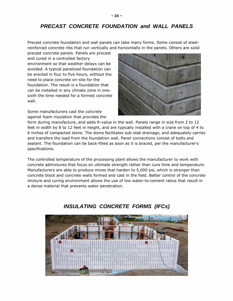
PRECAST CONCRETE FOUNDATION and WALL PANELS
Precast concrete foundation and wall panels can take many forms. Some consist of steel-
reinforced concrete ribs that run vertically and horizontally in the panels. Others are solid
precast concrete panels. Panels are precast
and cured in a controlled factory
environment so that weather delays can be
avoided. A typical panelized foundation can
be erected in four to five hours, without the
need to place concrete on-site for the
foundation. The result is a foundation that
can be installed in any climate zone in one-
sixth the time needed for a formed concrete
wall.
Some manufacturers cast the concrete
against foam insulation that provides the
form during manufacture, and adds R-value in the wall. Panels range in size from 2 to 12
feet in width by 8 to 12 feet in height, and are typically installed with a crane on top of 4 to
6 inches of compacted stone. The stone facilitates sub-slab drainage, and adequately carries
and transfers the load from the foundation wall. Panel connections consist of bolts and
sealant. The foundation can be back-filled as soon as it is braced, per the manufacturer's
specifications.
The controlled temperature of the processing plant allows the manufacturer to work with
concrete admixtures that focus on ultimate strength rather than cure time and temperature.
Manufacturers are able to produce mixes that harden to 5,000 psi, which is stronger than
concrete block and concrete walls formed and cast in the field. Better control of the concrete
mixture and curing environment allows the use of low water-to-cement ratios that result in
a dense material that prevents water penetration.
INSULATING CONCRETE FORMS (IFCs)
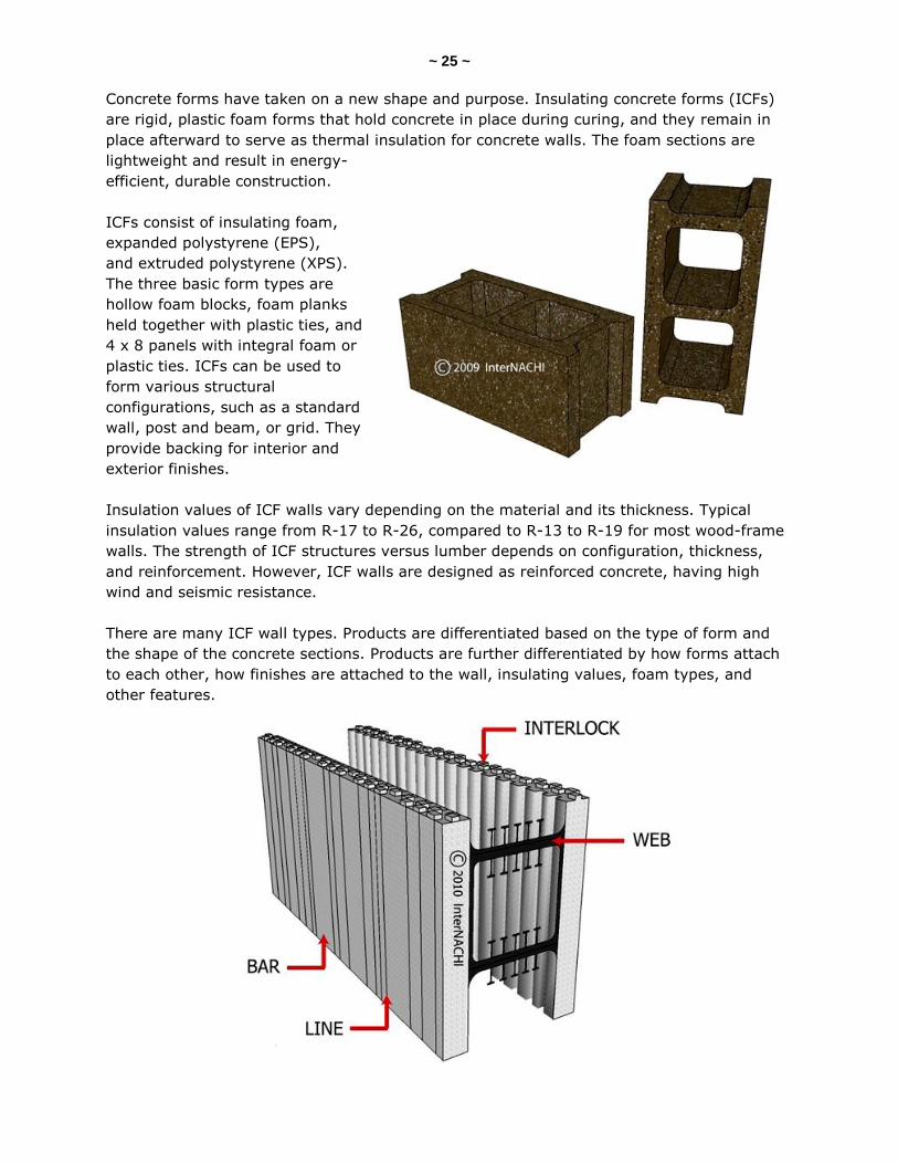
~ 25 ~ Concrete forms have taken on a new shape and purpose. Insulating concrete forms (ICFs)
are rigid, plastic foam forms that hold concrete in place during curing, and they remain in
place afterward to serve as thermal insulation for concrete walls. The foam sections are
lightweight and result in energy-
efficient, durable construction.
ICFs consist of insulating foam,
expanded polystyrene (EPS),
and extruded polystyrene (XPS).
The three basic form types are
hollow foam blocks, foam planks
held together with plastic ties, and
4 x 8 panels with integral foam or
plastic ties. ICFs can be used to
form various structural
configurations, such as a standard
wall, post and beam, or grid. They
provide backing for interior and
exterior finishes.
Insulation values of ICF walls vary depending on the material and its thickness. Typical
insulation values range from R-17 to R-26, compared to R-13 to R-19 for most wood-frame
walls. The strength of ICF structures versus lumber depends on configuration, thickness,
and reinforcement. However, ICF walls are designed as reinforced concrete, having high
wind and seismic resistance.
There are many ICF wall types. Products are differentiated based on the type of form and
the shape of the concrete sections. Products are further differentiated by how forms attach
to each other, how finishes are attached to the wall, insulating values, foam types, and
other features.
~ 26 ~
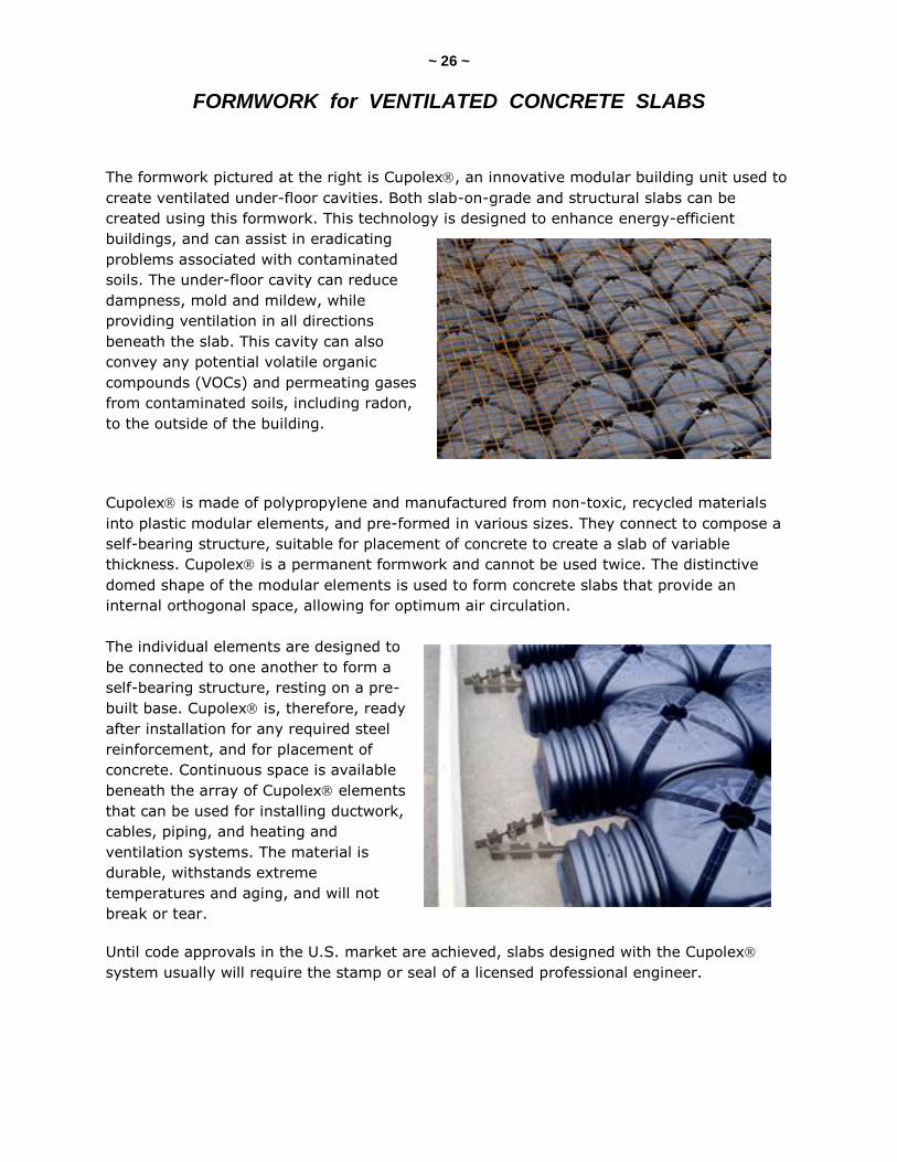
FORMWORK for VENTILATED CONCRETE SLABS
The formwork pictured at the right is Cupolex, an innovative modular building unit used to
create ventilated under-floor cavities. Both slab-on-grade and structural slabs can be
created using this formwork. This technology is designed to enhance energy-efficient
buildings, and can assist in eradicating
problems associated with contaminated
soils. The under-floor cavity can reduce
dampness, mold and mildew, while
providing ventilation in all directions
beneath the slab. This cavity can also
convey any potential volatile organic
compounds (VOCs) and permeating gases
from contaminated soils, including radon,
to the outside of the building.
Cupolex is made of polypropylene and manufactured from non-toxic, recycled materials
into plastic modular elements, and pre-formed in various sizes. They connect to compose a
self-bearing structure, suitable for placement of concrete to create a slab of variable
thickness. Cupolex is a permanent formwork and cannot be used twice. The distinctive
domed shape of the modular elements is used to form concrete slabs that provide an
internal orthogonal space, allowing for optimum air circulation.
The individual elements are designed to
be connected to one another to form a
self-bearing structure, resting on a pre-
built base. Cupolex is, therefore, ready
after installation for any required steel
reinforcement, and for placement of
concrete. Continuous space is available
beneath the array of Cupolex elements
that can be used for installing ductwork,
cables, piping, and heating and
ventilation systems. The material is
durable, withstands extreme
temperatures and aging, and will not
break or tear.
Until code approvals in the U.S. market are achieved, slabs designed with the Cupolex
system usually will require the stamp or seal of a licensed professional engineer.
~ 27 ~
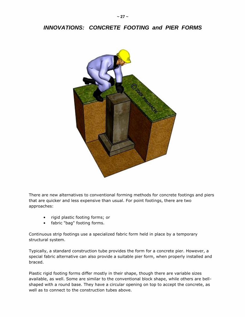
INNOVATIONS: CONCRETE FOOTING and PIER FORMS
There are new alternatives to conventional forming methods for concrete footings and piers
that are quicker and less expensive than usual. For point footings, there are two
approaches:
• rigid plastic footing forms; or
• fabric "bag" footing forms.
Continuous strip footings use a specialized fabric form held in place by a temporary
structural system.
Typically, a standard construction tube provides the form for a concrete pier. However, a
special fabric alternative can also provide a suitable pier form, when properly installed and
braced.
Plastic rigid footing forms differ mostly in their shape, though there are variable sizes
available, as well. Some are similar to the conventional block shape, while others are bell-
shaped with a round base. They have a circular opening on top to accept the concrete, as
well as to connect to the construction tubes above.
~ 28 ~ Rigid footing forms have ribs to provide extra strength, and some have small holes to
release air during the pour.
Fabric "bag" footing forms are exactly what their name implies. They are flexible fabric
sacks with a circular hole on top into which concrete is poured. The shape of the fabric form
approximates a standard rectangular footing, but all edges are rounded, with bowed sides,
and the form may be installed on and conform to uneven ground.
For footings that require rebar reinforcing, there is a form sack which has a zipper to open
the top of the "bag" enough to get the reinforcing rods inside the fabric form before placing
the concrete.
Additionally, there is a foundation pier product developed specifically for manufactured
housing that uses footing form bags as a key part of its design.
Fabric strip footing forms can be used for level and step footings, as well as for deep
footings, and they can be installed over uneven ground and rock (if it is structurally
acceptable to do so). A simple, temporary form must be built, to which the fabric attaches
in order to hold its shape while the concrete cures. This is made with a board on each side
that defines the top edge of the form to which the fabric attaches, held at the required
height and width by a special "yoke" support system. Long boards that hold the fabric in
place must be stabilized laterally. This is achieved by regularly spaced metal stakes
pounded into the ground along either side of the form. Once the concrete sets, the rigid
formwork may be removed and reused, while the fabric form remains in place.
There is a proprietary foundation pier product called The Buttress, which combines the
fabric bag with a steel pier, and which has been developed specifically for the HUD-code
housing market.
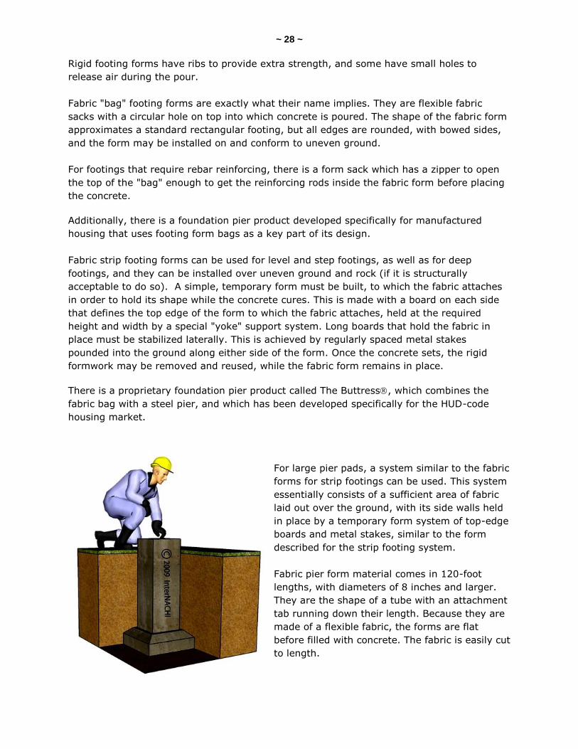
For large pier pads, a system similar to the fabric
forms for strip footings can be used. This system
essentially consists of a sufficient area of fabric
laid out over the ground, with its side walls held
in place by a temporary form system of top-edge
boards and metal stakes, similar to the form
described for the strip footing system.
Fabric pier form material comes in 120-foot
lengths, with diameters of 8 inches and larger.
They are the shape of a tube with an attachment
tab running down their length. Because they are
made of a flexible fabric, the forms are flat
before filled with concrete. The fabric is easily cut
to length.
~ 29 ~
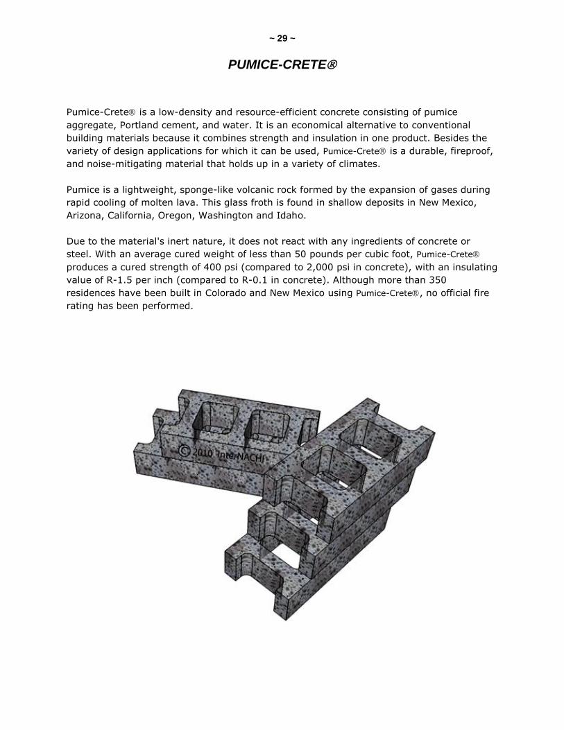
PUMICE-CRETE
Pumice-Crete is a low-density and resource-efficient concrete consisting of pumice
aggregate, Portland cement, and water. It is an economical alternative to conventional
building materials because it combines strength and insulation in one product. Besides the
variety of design applications for which it can be used, Pumice-Crete is a durable, fireproof,
and noise-mitigating material that holds up in a variety of climates.
Pumice is a lightweight, sponge-like volcanic rock formed by the expansion of gases during
rapid cooling of molten lava. This glass froth is found in shallow deposits in New Mexico,
Arizona, California, Oregon, Washington and Idaho.
Due to the material's inert nature, it does not react with any ingredients of concrete or
steel. With an average cured weight of less than 50 pounds per cubic foot, Pumice-Crete
produces a cured strength of 400 psi (compared to 2,000 psi in concrete), with an insulating
value of R-1.5 per inch (compared to R-0.1 in concrete). Although more than 350
residences have been built in Colorado and New Mexico using Pumice-Crete, no official fire
rating has been performed.

~ 30 ~
INNOVATIONS: CONCRETE AGGREGATE SUBSTITUTES
Conventional concrete aggregate consists of sand (fine aggregate) and various sizes and
shapes of gravel and stones. However, there is a growing interest in substituting alternative
aggregate materials largely as a potential use for recycled materials.
There is significant research on many different materials for aggregate substitutes, such as
granulated coal ash, blast-furnace slag, and various solid wastes, including fiberglass waste
materials, granulated plastics, paper and wood products and waste, sintered sludge pellets,
and similar materials. However, the only two materials that have been significantly applied
are glass cullet and crushed recycled concrete itself.
Even though aggregate typically accounts for 70% to 80% of the concrete volume, it is
commonly thought of as inert filler having little effect on the finished concrete's properties.
However, research has shown that aggregate plays a substantial role in determining
workability, strength, dimensional stability, and durability of the concrete.
Also, aggregates can have a significant effect on the cost of the concrete mixture. Certain
aggregate parameters are known to be important for engineered-use concrete, including
hardness, strength and durability. The aggregate must be "clean," without absorbed
chemicals, clay coatings, or other fine materials in concentrations that could alter the
hydration and bond of the cement paste.
It is important to note the differences between aggregate and cement because some
materials use both as a cementitious material and as aggregate (such as certain blast-
furnace slags).
Aggregate composed of recycled concrete generally has a lower specific gravity and a higher
absorption rate than conventional gravel aggregate. New concrete made with recycled
concrete aggregate typically has good workability, durability and resistance to saturated
freeze-thaw action. The compressive strength varies with the compressive strength of the
original concrete and the water-to-cement ratio of the new concrete. It has been found that
concrete made with recycled concrete aggregate has at least two-thirds the compressive
strength and modulus of elasticity of natural aggregate concrete.
Field testing has shown that crushed and screened waste glass may be used as a sand
substitute in concrete. Nearly all waste glass can be used in concrete applications, including
glass that is unsuitable for uses such as glass bottle recycling. Some of the specific glass
waste materials that have found use as fine aggregate are "non-recyclable" clear window
glass, and fluorescent bulbs with very small amounts of contaminants. Possible applications
for such waste-glass concrete are bike paths, footpaths, gutters, and similar non-structural
work.
The current lack of widespread, reliable data on aggregate substitutes can hinder its use. To
design consistent, durable recycled-aggregate concrete, more testing is required to account
for variations in the aggregate's properties. Also, recycled aggregate generally has a higher
absorption rate and a lower specific gravity than conventional aggregate.
~ 31 ~ Research has revealed that the seven-day and 28-day compressive strengths of recycled-
aggregate concrete are generally lower than values for conventional concrete. Moreover,
recycled aggregates may be contaminated with residual quantities of sulfate from contact
with sulfate-rich soil and chloride ions from marine exposure.
Glass aggregate in concrete can be problematic due to the alkali-silica reaction between the
cement paste and the glass aggregate which, over time, can lead to weakened concrete and
decreased long-term durability. Research has been done on types of glass and other
additives to stop or decrease the alkali-silica reaction and, thereby, maintain finished
concrete strength. However, further research is still needed before glass cullet can be used
in structural concrete applications.
~ 32 ~
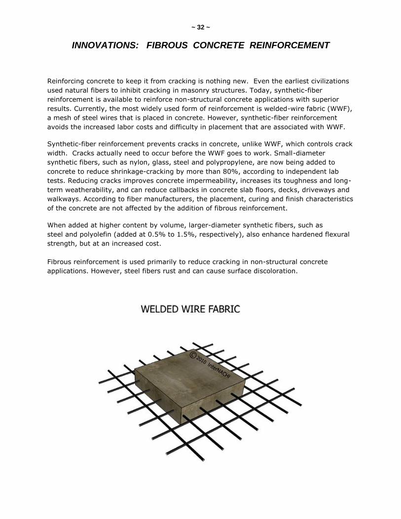
INNOVATIONS: FIBROUS CONCRETE REINFORCEMENT
Reinforcing concrete to keep it from cracking is nothing new. Even the earliest civilizations
used natural fibers to inhibit cracking in masonry structures. Today, synthetic-fiber
reinforcement is available to reinforce non-structural concrete applications with superior
results. Currently, the most widely used form of reinforcement is welded-wire fabric (WWF),
a mesh of steel wires that is placed in concrete. However, synthetic-fiber reinforcement
avoids the increased labor costs and difficulty in placement that are associated with WWF.
Synthetic-fiber reinforcement prevents cracks in concrete, unlike WWF, which controls crack
width. Cracks actually need to occur before the WWF goes to work. Small-diameter
synthetic fibers, such as nylon, glass, steel and polypropylene, are now being added to
concrete to reduce shrinkage-cracking by more than 80%, according to independent lab
tests. Reducing cracks improves concrete impermeability, increases its toughness and long-
term weatherability, and can reduce callbacks in concrete slab floors, decks, driveways and
walkways. According to fiber manufacturers, the placement, curing and finish characteristics
of the concrete are not affected by the addition of fibrous reinforcement.
When added at higher content by volume, larger-diameter synthetic fibers, such as
steel and polyolefin (added at 0.5% to 1.5%, respectively), also enhance hardened flexural
strength, but at an increased cost.
Fibrous reinforcement is used primarily to reduce cracking in non-structural concrete
applications. However, steel fibers rust and can cause surface discoloration.

~ 33 ~
INNOVATIONS: AUTOCLAVED AERATED CONCRETE (AAC)
Builders in the U.S. can use an innovative concrete
material that Scandinavians have used for decades.
Autoclaved aerated concrete (AAC) is a precast
structural product made with natural raw materials. In
1914, the Swedes invented a mixture of cement, lime,
water and sand that expands by adding aluminum
powder. The material was further developed to what we
know today as autoclaved aerated concrete, which
is also called autoclaved cellular concrete.
It is an economical, sustainable, solid block that
provides thermal and acoustic insulation, as well as fire
and termite resistance. AAC is available in a variety of forms, ranging from wall and roof
panels to blocks and lintels. Although it has been a popular building material in Europe
for over 50 years, AAC has only been introduced to the U.S. in the past two decades.
To manufacture AAC, Portland cement is mixed with lime, silica sand or recycled fly ash
(a byproduct from coal-burning power plants), water, and aluminum powder or paste, and
then poured into a mold. The reaction between aluminum and concrete causes microscopic
hydrogen bubbles to form, expanding the concrete to about five times its original volume.
After the hydrogen evaporates, the now highly aerated concrete is cut to size and formed by
steam-curing in a pressurized chamber -- an autoclave. The result is a non-organic, non-
toxic, airtight material that can be used for wall, floor and roof panels, blocks and lintels,
and which, according to the manufacturers, generates no pollutants or hazardous waste
during the manufacturing process.
AAC units are available in numerous shapes and sizes. Panels are 24 inches wide, between 8
to 12 inches thick, and up to 20 feet long. Blocks come in lengths of 24 inches, 32 inches
and 48 inches, between 4 to 16 inches thick, and 8 inches high.
AAC features include structural capacity, thermal, fire and acoustical resistance properties.
With an R-value of approximately 1.25 per inch, depending on density, AAC significantly
out-performs conventional concrete block and poured concrete. Consistency in quality and
color may be difficult to obtain in AAC made with fly ash. Unfinished exterior walls should be
covered with an exterior cladding, or parged with mortar, when exposed to physical
damage, dirt and water because atmospheric debris can collect in the open cells. If installed
in high-humidity environments, interior finishes with low-vapor permeability and exterior
finishes with a high-permeability are recommended.
Because of the thermal mass of AAC and its ability to store and release energy over time,
AAC may be beneficial in climates where outdoor temperature fluctuates over a 24-hour
period from above to below the indoor temperature conditioned air-set point.
~ 34 ~
CRACKING in CONCRETE
Cracking Associated with Drying Shrinkage in Concrete Block Foundation Walls
The shrinkage of concrete block walls during the drying process will often result in patterns
of cracking similar to that caused by differential settlement: tapering cracks that widen as
they move, resulting in a diagonal upward pattern. These cracks usually form during the
building’s first year and, in existing buildings, will appear as “old” cracks and exhibit no
further movement. Although such cracks are often mistaken for settlement cracks,
shrinkage cracks usually occur in the middle third of the wall, and the footer beneath them
remains intact. Shrinkage cracking is rarely serious and, in an older building, may have
been previously repaired. If the wall is unsound, its structural integrity can sometimes be
restored by pressure-injecting concrete epoxy grout into the cracks, or by adding pilasters.
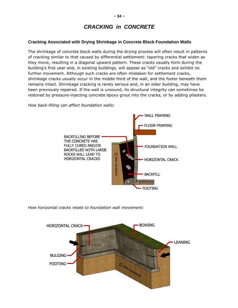
How back-filling can affect foundation walls:
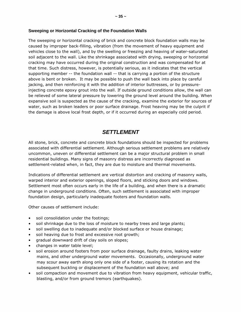
How horizontal cracks relate to foundation wall movement:
~ 35 ~
Sweeping or Horizontal Cracking of the Foundation Walls
The sweeping or horizontal cracking of brick and concrete block foundation walls may be
caused by improper back-filling, vibration (from the movement of heavy equipment and
vehicles close to the wall), and by the swelling or freezing and heaving of water-saturated
soil adjacent to the wall. Like the shrinkage associated with drying, sweeping or horizontal
cracking may have occurred during the original construction and was compensated for at
that time. Such distress, however, is potentially serious, as it indicates that the vertical
supporting member -- the foundation wall -- that is carrying a portion of the structure
above is bent or broken. It may be possible to push the wall back into place by careful
jacking, and then reinforcing it with the addition of interior buttresses, or by pressure-
injecting concrete epoxy grout into the wall. If outside ground conditions allow, the wall can
be relieved of some lateral pressure by lowering the ground level around the building. When
expansive soil is suspected as the cause of the cracking, examine the exterior for sources of
water, such as broken leaders or poor surface drainage. Frost heaving may be the culprit if
the damage is above local frost depth, or if it occurred during an especially cold period.
SETTLEMENT
All stone, brick, concrete and concrete block foundations should be inspected for problems
associated with differential settlement. Although serious settlement problems are relatively
uncommon, uneven or differential settlement can be a major structural problem in small
residential buildings. Many signs of masonry distress are incorrectly diagnosed as
settlement-related when, in fact, they are due to moisture and thermal movements.
Indications of differential settlement are vertical distortion and cracking of masonry walls,
warped interior and exterior openings, sloped floors, and sticking doors and windows.
Settlement most often occurs early in the life of a building, and when there is a dramatic
change in underground conditions. Often, such settlement is associated with improper
foundation design, particularly inadequate footers and foundation walls.
Other causes of settlement include:
• soil consolidation under the footings;
• soil shrinkage due to the loss of moisture to nearby trees and large plants;
• soil swelling due to inadequate and/or blocked surface or house drainage;
• soil heaving due to frost and excessive root growth;
• gradual downward drift of clay soils on slopes;
• changes in water table level;
• soil erosion around footers from poor surface drainage, faulty drains, leaking water
mains, and other underground water movements. Occasionally, underground water
may scour away earth along only one side of a footer, causing its rotation and the
subsequent buckling or displacement of the foundation wall above; and
• soil compaction and movement due to vibration from heavy equipment, vehicular traffic,
blasting, and/or from ground tremors (earthquakes).
~ 36 ~ Gradual differential settlement over a long period of time may produce no masonry cracking
at all, particularly in walls with older and softer bricks and high lime mortars; instead, the
wall will elastically deform.
More rapid settlement, however, produces cracks that taper, starting large at one end and
then diminishing to a hairline crack at the other end, depending on the direction and
location of settlement below the wall. Cracking is most likely to occur at corners and
adjacent to openings, and usually follows a rough diagonal path along mortar joints,
although individual masonry units may be split.
Settlement cracks (as opposed to the similar-appearing shrinkage cracks that are especially
prevalent in concrete block) may extend through contiguous building elements, such as
floor slabs, masonry walls above the foundation, and interior plaster work. Tapering cracks,
or cracks that are nearly vertical and whose edges do not line up, may occur at the joints of
projecting bay windows, porches, and additions. These cracks indicate differential
settlement due to inadequate foundations or piers under the projecting element.
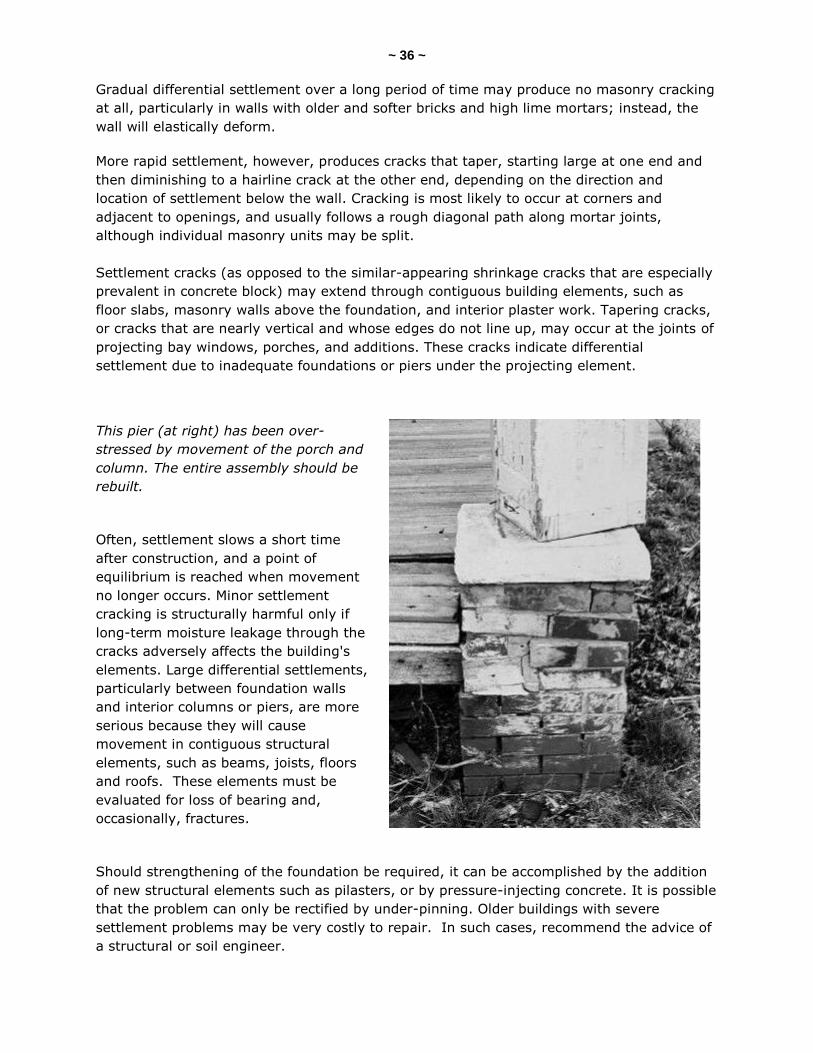
This pier (at right) has been over-
stressed by movement of the porch and
column. The entire assembly should be
rebuilt.
Often, settlement slows a short time
after construction, and a point of
equilibrium is reached when movement
no longer occurs. Minor settlement
cracking is structurally harmful only if
long-term moisture leakage through the
cracks adversely affects the building's
elements. Large differential settlements,
particularly between foundation walls
and interior columns or piers, are more
serious because they will cause
movement in contiguous structural
elements, such as beams, joists, floors
and roofs. These elements must be
evaluated for loss of bearing and,
occasionally, fractures.
Should strengthening of the foundation be required, it can be accomplished by the addition
of new structural elements such as pilasters, or by pressure-injecting concrete. It is possible
that the problem can only be rectified by under-pinning. Older buildings with severe
settlement problems may be very costly to repair. In such cases, recommend the advice of
a structural or soil engineer.
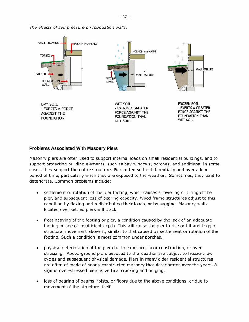
~ 37 ~ The effects of soil pressure on foundation walls:
Problems Associated With Masonry Piers
Masonry piers are often used to support internal loads on small residential buildings, and to
support projecting building elements, such as bay windows, porches, and additions. In some
cases, they support the entire structure. Piers often settle differentially and over a long
period of time, particularly when they are exposed to the weather. Sometimes, they tend to
deteriorate. Common problems include:
settlement or rotation of the pier footing, which causes a lowering or tilting of the
pier, and subsequent loss of bearing capacity. Wood frame structures adjust to this
condition by flexing and redistributing their loads, or by sagging. Masonry walls
located over settled piers will crack.
frost heaving of the footing or pier, a condition caused by the lack of an adequate
footing or one of insufficient depth. This will cause the pier to rise or tilt and trigger
structural movement above it, similar to that caused by settlement or rotation of the
footing. Such a condition is most common under porches.
physical deterioration of the pier due to exposure, poor construction, or over-
stressing. Above-ground piers exposed to the weather are subject to freeze-thaw
cycles and subsequent physical damage. Piers in many older residential structures
are often of made of poorly constructed masonry that deteriorates over the years. A
sign of over-stressed piers is vertical cracking and bulging.
loss of bearing of beams, joists, or floors due to the above conditions, or due to
movement of the structure itself.
~ 38 ~ Piers should be examined for signs of settlement and their adequacy in accepting bearing
loads. Inspectors should note their condition and ensure that they are plumb. Check their
width-to-height ratio, which should not exceed 1:10. Piers that are deficient should be
repaired or replaced. When appearance is not a factor (as is often the case), piers can be
supplemented by the addition of adjacent supports.
BRICK VENEER WALLS
Problems Associated With Brick Veneer Walls
Brick veneer walls are subject to the forces of differential settlement, moisture and thermal-
related cracking, and the effects of freezing and corrosion. Common problems particular to
brick veneer walls are:
cracks caused by wood frame shrinkage, which are most likely to be found around
fixed openings where the independent movement of the veneer wall is restrained.
These cracks are also formed early in the life of the building and can be repaired by
pointing;
bulging, which is caused by inadequate or deteriorated ties between the brick and
the wall to which it’s held; and
vertical cracking at corners, and/or horizontal cracking near the ground, which is
caused by thermal movement of the wall. This cracking is similar to that in solid
masonry and masonry cavity walls, but possibly more pronounced in well-insulated
buildings because of the reduction in the moderating effect from interior
temperatures. Thermal cracks are cyclical and should be filled with a flexible sealant.
In cases of severe cracking, expansion joints may have to be installed.
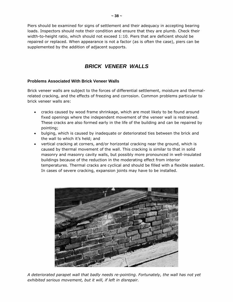
A deteriorated parapet wall that badly needs re-pointing. Fortunately, the wall has not yet
exhibited serious movement, but it will, if left in disrepair.

~ 39 ~
QUIZ 2
1. Retarding admixtures slow down the hydration of cement, which lengthens its ______.
amount
lifespan
set time
2. Accelerating admixtures ________ the set time of concrete.
shorten
eliminate
lengthen
3. Super-plasticizers are ____________.
"free-range water inhibitors"
"low-range water reducers"
"high-range water reducers"
4. Water-reducing admixtures are mostly used for ____________.
hot-weather concrete placing
high-altitude concrete placing
cold-weather concrete placing
5. Air-entraining admixtures entrain __________ in the concrete.
small water droplets
small air bubbles
dry concrete dust
6. T/F: Admixtures can usually compensate for poor workmanship and low-quality materials.
True
False
7. _________ cracks are often mistaken for settlement cracks.
Shrinkage
Frost-heave
Seismic
(continued)
~ 40 ~
8. Sweeping cracks in the foundation are ______________.
primarily cosmetic in nature
common and non-serious
potentially serious
9. Rapid settlement produces ________ cracks.
serious
tapering
widening
10. T/F: Frozen soil exerts a greater force against the foundation than wet soil.
True
False
11. T/F: Inspectors should note the condition of masonry piers and ensure that they are plumb.
True
False
12. Some causes of foundation settlement include: _____________.
soil erosion
soil compaction
soil swelling
soil shrinkage
all of these
Answer Key is on the next page.
~ 41 ~
Answer Key to Quiz 2
1. Retarding admixtures slow down the hydration of cement, which lengthens its set time.
2. Accelerating admixtures shorten the set time of concrete.
3. Super-plasticizers are “high-range water reducers.”
4. Water-reducing admixtures are mostly used for hot-weather concrete placing.
5. Air-entraining admixtures entrain small air bubbles in the concrete.
6. T/F: Admixtures can usually compensate for poor workmanship and low-quality materials. Answer: False
7. Shrinkage cracks are often mistaken for settlement cracks.
8. Sweeping cracks in the foundation are potentially serious.
9. Rapid settlement produces tapering cracks.
10. T/F: Frozen soil exerts a greater force against the foundation than wet soil. Answer: True
11. T/F: Inspectors should note the condition of masonry piers and ensure that they are plumb. Answer: True
12. Some causes of foundation settlement include: all of these.
~ 42 ~
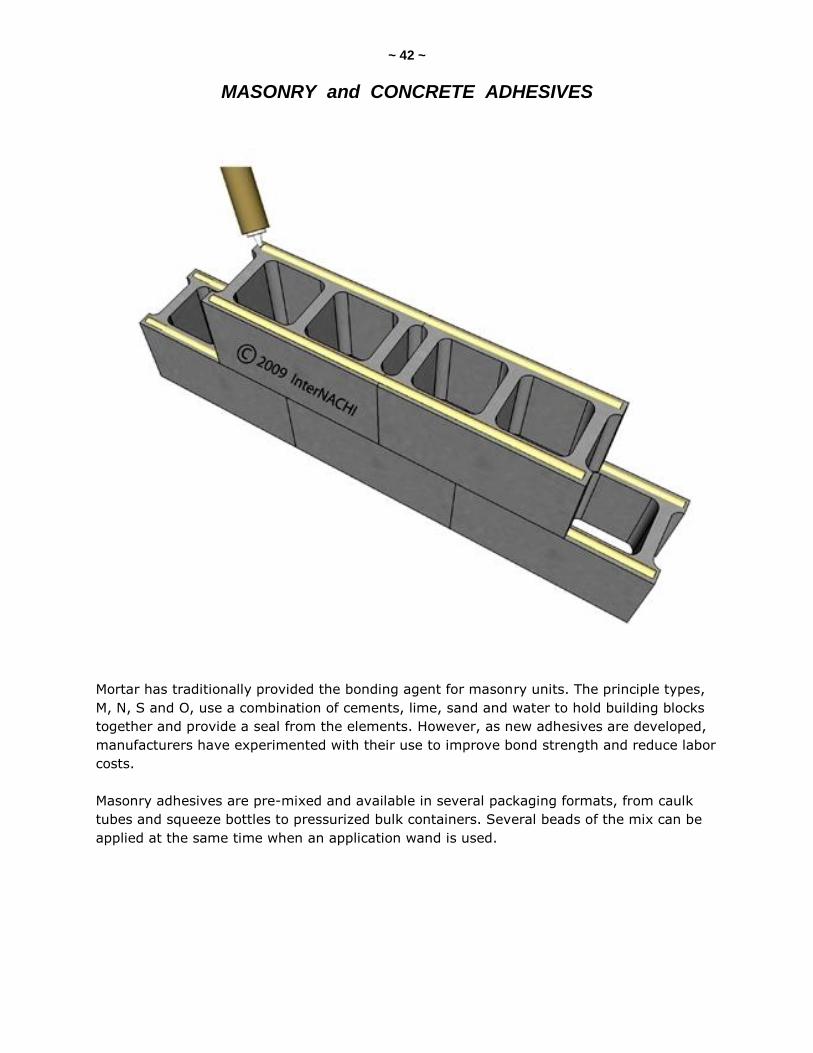
MASONRY and CONCRETE ADHESIVES
Mortar has traditionally provided the bonding agent for masonry units. The principle types,
M, N, S and O, use a combination of cements, lime, sand and water to hold building blocks
together and provide a seal from the elements. However, as new adhesives are developed,
manufacturers have experimented with their use to improve bond strength and reduce labor
costs.
Masonry adhesives are pre-mixed and available in several packaging formats, from caulk
tubes and squeeze bottles to pressurized bulk containers. Several beads of the mix can be
applied at the same time when an application wand is used.
~ 43 ~
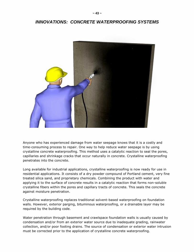
INNOVATIONS: CONCRETE WATERPROOFING SYSTEMS
Anyone who has experienced damage from water seepage knows that it is a costly and
time-consuming process to repair. One way to help reduce water seepage is by using
crystalline concrete waterproofing. This method uses a catalytic reaction to seal the pores,
capillaries and shrinkage cracks that occur naturally in concrete. Crystalline waterproofing
penetrates into the concrete.
Long available for industrial applications, crystalline waterproofing is now ready for use in
residential applications. It consists of a dry powder compound of Portland cement, very fine
treated silica sand, and proprietary chemicals. Combining the product with water and
applying it to the surface of concrete results in a catalytic reaction that forms non-soluble
crystalline fibers within the pores and capillary tracts of concrete. This seals the concrete
against moisture penetration.
Crystalline waterproofing replaces traditional solvent-based waterproofing on foundation
walls. However, exterior parging, bituminous waterproofing, or a drainable layer may be
required by the building code.
Water penetration through basement and crawlspace foundation walls is usually caused by
condensation and/or from an exterior water source due to inadequate grading, rainwater
collection, and/or poor footing drains. The source of condensation or exterior water intrusion
must be corrected prior to the application of crystalline concrete waterproofing.
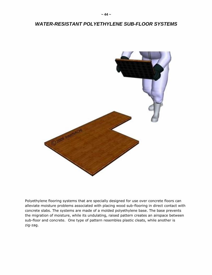
~ 44 ~
WATER-RESISTANT POLYETHYLENE SUB-FLOOR SYSTEMS
Polyethylene flooring systems that are specially designed for use over concrete floors can
alleviate moisture problems associated with placing wood sub-flooring in direct contact with
concrete slabs. The systems are made of a molded polyethylene base. The base prevents
the migration of moisture, while its undulating, raised pattern creates an airspace between
sub-floor and concrete. One type of pattern resembles plastic cleats, while another is
zig-zag.
~ 45 ~
FOUNDATION DRAINAGE PANELS
The foundation is a vulnerable place for water intrusion. Improper drainage around the
foundation is a major cause of leaking foundations. When a drainage system is used in
residential construction, it is usually a combination of a layer of gravel for drainage with a
foundation drain, usually either drain tile or perforated PVC pipe. Months later, as drainage
occurs, small soil particles can fill the drainage path, resulting in reduced drainage of ground
water. Water pressure then builds up and eventually causes leakage through the foundation
wall.
Engineered, prefabricated foundation drainage panels are designed to facilitate the
movement of ground water, which reduces the stress of the water pressure on the
foundation's waterproofing. The drainage panels provide an unobstructed path from the
surface grade to the footing, allowing the footing drain to collect and move water away from
around the foundation. Some of these systems also provide thermal resistance and can
reduce interior condensation.
Foundation drainage panel systems combine with waterproofing membranes to provide
protection from ground water in areas where there is a high water table and/or hydrostatic
pressure. The standard gravel drainage course and foundation drains with damp-proofing on
the foundation are applicable in areas with occasional or no groundwater.
The typical foundation drainage system consists of a waterproofing membrane at the
foundation with a pre-formed path, such as a grid system or a solid porous board, and a
filter to keep the drain path clear of small particle buildup. The filter is usually a course of
specially-graded aggregates, ranging from crushed stone and gravel to coarse, angular
sand. Geotechnical fabrics, commonly called "filter fabrics," are now frequently used to
allow the flow of water while preventing small particles from passing through. These fabrics
use less space, are more reliable, and are relatively easy to install.
The drainage path can be designed using several different methods:
a solid drainage board with a porous structure, allowing moisture and water to drain
vertically down to the foundation drain. These board-type systems provide protection
of the waterproof membrane and thermal insulation;
an air space created by a dimpled plastic grid, or "geogrid." Condensation can also
be collected in this air space;
a traditional gravel course, with filter fabric to the outside, and a protection board
over the foundation waterproofing. Washed pea-gravel and screened crushed stone
work well for this drainage course; and
panels with an air space to quickly move the water to the drains, reducing
hydrostatic pressure against the foundation.
Most of these systems also provide protection to the damp-proof or waterproof membrane.
~ 46 ~ Dimpled polyethylene sheets can be used in two ways:
with the dimples toward the foundation wall. This provides an air space for
condensation, using the backside as an impervious barrier. When properly sealed,
the system resists ground water percolating through to the face of the foundation,
thereby protecting it from the moisture.
some products have a filter fabric adhered to the dimple-side of the panel. In this
case, the flat side of the panel is placed toward the foundation. The drainage path is
created by the dimples, and protected by the filter fabric.
Another method for providing a path with the filter fabric is the use of a "geogrid." A geogrid
is a twisted-wire plastic mesh, often shaped into a diamond-lath pattern, faced with filter
fabric. These are normally rather thin, flat membranes offering effective drainage
characteristics in a minimal space.
Enkadrain™ employs a fused, entangled polymer filament geomatrix, or plastic wire mesh,
faced with filter fabric to provide the drainage layer.
The American Wick Drain Corporation makes a sheet-drain system connected to a strip
drain at the bottom of the foundation wall. The strip drain can be connected to piping to
lead the water away from the foundation.
Form-a-Drain, made by the Certainteed Corporation, is a rectangular drainage conduit that
also acts as a footing form, saving several installation steps.
Foam plastic insulated panels may be used outside foundation walls to move water to drain
tile or pipe at the bottom of the wall. As mentioned previously, these panels also provide
thermal insulation. Panels may or may not be faced with a geotextile membrane. Geotech™,
for example, is an un-faced board of expanded polystyrene. It allows water to move
between the bead structure of the material, and the polystyrene offers insulating value.
Other foam foundation panels are made from extruded polystyrene, grooved on the soil-side
and covered with filter fabric. The filter fabric allows the water to enter the grooves which,
in turn, transfers it to the drain tile. The polystyrene insulation has a low permeability
rating, and provides insulative value.
Some drainage panels are composed of rock (mineral), wool, and fiberglass material
oriented to provide vertical drainage to the foundation drain. No filter fabric is necessary
with these materials.
~ 47 ~
FOUNDATION FLOOD VENTS
To be eligible for flood insurance through FEMA's National Flood Insurance Program (NFIP),
foundations must be constructed with certain flood damage-mitigation features. In coastal
areas and riverine zones where high-velocity floodwaters can occur, homes must be
elevated on open-pile foundations, and enclosures below the living space must be located at
an elevation higher than the 100-year base flood elevation and must be designed to break
away in a storm surge.
Homes built in floodplains where floodwater velocity levels are lower than coastlines and
riverine zones (less than 5 feet per second), and on perimeter-type foundations, should be
designed so that the exterior walls of the foundation automatically equalize hydrostatic flood
forces by allowing for the free flow of floodwater. This minimizes structural flood damage by
reducing the horizontal hydrostatic force that unbalanced water levels impose on foundation
walls.
Foundation designs meeting NFIP requirements must include prescribed openings or an
engineer's certification that the following minimum criteria have been met:
A minimum of two openings (on different foundation wall elevations) having a total
net area of not less than 1 square inch for every square foot of enclosed area subject
to flooding shall be provided.
The bottom of all openings shall be no higher than 1 foot above grade.
Openings may be equipped with screens, louvers, valves, or other coverings or
devices, provided that they permit the automatic entry and exit of floodwaters.
Any openings that allow for the free flow of floodwater into or out of a foundation will meet
NFIP requirements, subject to minimum size and location criteria. Even voids in the
continuity of a block foundation (or "blocks turned sideways," as one Maryland Department
of the Environment technical note refers to it) will suffice.
Depending on their method of operation, conventional crawlspace ventilation grills may also
serve to equalize water around the foundation during a flood. However, some air vents that
are thermostatically controlled may not disengage in cold weather to allow water entry. If
crawlspace vents will also be used as floodwater vents, the number and location of vents to
be used should be specified, based on the floodwater vent criteria.
Several manufacturers have developed unitized, shuttered products that meet the minimum
flood venting requirements of NFIP. Smart Vent, Inc. markets several types of vents,
including the Smart VENT®, which automatically opens and closes as floodwaters rise and
fall. It also features temperature-controlled louvers which open in warm weather to provide
50 inches of net-free ventilation area, and then close in cold weather.
Each Smart VENT®, sized 8x16 inches, is certified to protect 200 square feet of foundation
area. Another model, Flood VENT™, is used when flood protection, not ventilation, is
needed. This model has a non-vented insulated door that minimizes heat loss, air leakage,
and pest intrusion when the door is closed, but swings open during a flood. Another
manufacturer, Floodex, has obtained pre-certification of its floodwater vent.
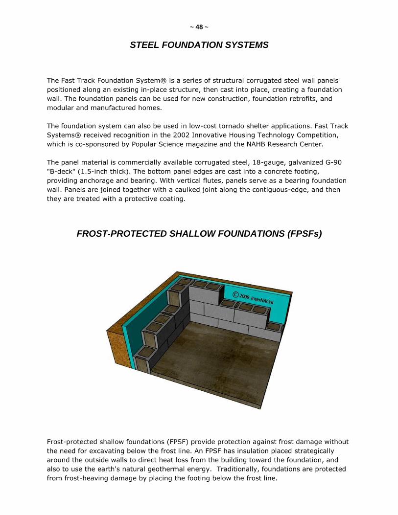
~ 48 ~
STEEL FOUNDATION SYSTEMS
The Fast Track Foundation System® is a series of structural corrugated steel wall panels
positioned along an existing in-place structure, then cast into place, creating a foundation
wall. The foundation panels can be used for new construction, foundation retrofits, and
modular and manufactured homes.
The foundation system can also be used in low-cost tornado shelter applications. Fast Track
Systems® received recognition in the 2002 Innovative Housing Technology Competition,
which is co-sponsored by Popular Science magazine and the NAHB Research Center.
The panel material is commercially available corrugated steel, 18-gauge, galvanized G-90
"B-deck" (1.5-inch thick). The bottom panel edges are cast into a concrete footing,
providing anchorage and bearing. With vertical flutes, panels serve as a bearing foundation
wall. Panels are joined together with a caulked joint along the contiguous-edge, and then
they are treated with a protective coating.
FROST-PROTECTED SHALLOW FOUNDATIONS (FPSFs)
Frost-protected shallow foundations (FPSF) provide protection against frost damage without
the need for excavating below the frost line. An FPSF has insulation placed strategically
around the outside walls to direct heat loss from the building toward the foundation, and
also to use the earth's natural geothermal energy. Traditionally, foundations are protected
from frost-heaving damage by placing the footing below the frost line.

~ 49 ~ Because FPSFs are protected from freezing by thermal insulation, the bottoms of footings
can be just 12 to 16 inches below grade. This reduces excavation costs, making FPSFs an
economical alternative for protecting foundations against frost damage.
Insulated footings have been in use since as early as the 1930s by Frank Lloyd Wright in the
Chicago area. There are now more than 1 million homes in Norway, Sweden and Finland
with insulated shallow footings, recognized by their building codes as standard practice. It is
estimated that there are more than 5,000 buildings in the United States that have
successfully used frost-protected shallow foundations.
FPSFs are similar to conventional foundations except in insulation placement and footing
depth. The bottoms of FPSF footings are placed about 12 to 16 inches below grade. FPSFs
have vertical insulation placed at the outside edge of the foundation, extending from above
grade to the bottom of the footing.
When required in colder climates, "wing" insulation extends outward horizontally from the
footing. The colder the climate, the further the wing insulation is extended. Wing insulation
is unnecessary in moderate climates.
The insulation used in FPSFs is commonly rigid expanded or extruded polystyrene foam
suitable for below-grade application, and it must be in compliance with ASTM C 578
Standards. An FPSF can be used for both heated and unheated portions of a building.
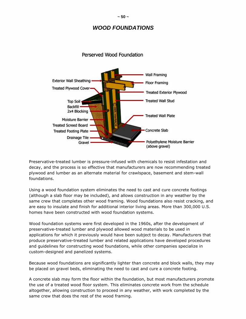
~ 50 ~
WOOD FOUNDATIONS
Preservative-treated lumber is pressure-infused with chemicals to resist infestation and
decay, and the process is so effective that manufacturers are now recommending treated
plywood and lumber as an alternate material for crawlspace, basement and stem-wall
foundations.
Using a wood foundation system eliminates the need to cast and cure concrete footings
(although a slab floor may be included), and allows construction in any weather by the
same crew that completes other wood framing. Wood foundations also resist cracking, and
are easy to insulate and finish for additional interior living areas. More than 300,000 U.S.
homes have been constructed with wood foundation systems.
Wood foundation systems were first developed in the 1960s, after the development of
preservative-treated lumber and plywood allowed wood materials to be used in
applications for which it previously would have been subject to decay. Manufacturers that
produce preservative-treated lumber and related applications have developed procedures
and guidelines for constructing wood foundations, while other companies specialize in
custom-designed and panelized systems.
Because wood foundations are significantly lighter than concrete and block walls, they may
be placed on gravel beds, eliminating the need to cast and cure a concrete footing.
A concrete slab may form the floor within the foundation, but most manufacturers promote
the use of a treated wood floor system. This eliminates concrete work from the schedule
altogether, allowing construction to proceed in any weather, with work completed by the
same crew that does the rest of the wood framing.
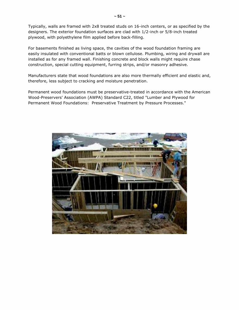
~ 51 ~ Typically, walls are framed with 2x8 treated studs on 16-inch centers, or as specified by the
designers. The exterior foundation surfaces are clad with 1/2-inch or 5/8-inch treated
plywood, with polyethylene film applied before back-filling.
For basements finished as living space, the cavities of the wood foundation framing are
easily insulated with conventional batts or blown cellulose. Plumbing, wiring and drywall are
installed as for any framed wall. Finishing concrete and block walls might require chase
construction, special cutting equipment, furring strips, and/or masonry adhesive.
Manufacturers state that wood foundations are also more thermally efficient and elastic and,
therefore, less subject to cracking and moisture penetration.
Permanent wood foundations must be preservative-treated in accordance with the American
Wood-Preservers' Association (AWPA) Standard C22, titled "Lumber and Plywood for
Permanent Wood Foundations: Preservative Treatment by Pressure Processes."
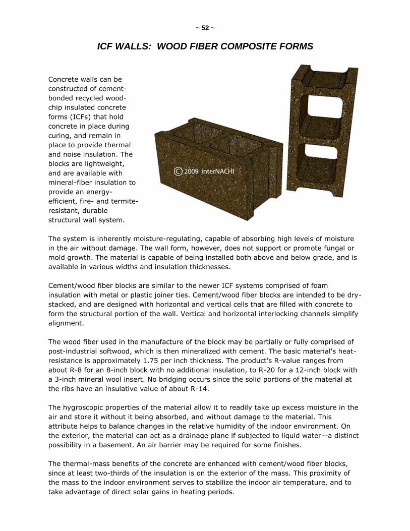
~ 52 ~
ICF WALLS: WOOD FIBER COMPOSITE FORMS
Concrete walls can be
constructed of cement-
bonded recycled wood-
chip insulated concrete
forms (ICFs) that hold
concrete in place during
curing, and remain in
place to provide thermal
and noise insulation. The
blocks are lightweight,
and are available with
mineral-fiber insulation to
provide an energy-
efficient, fire- and termite-
resistant, durable
structural wall system.
The system is inherently moisture-regulating, capable of absorbing high levels of moisture
in the air without damage. The wall form, however, does not support or promote fungal or
mold growth. The material is capable of being installed both above and below grade, and is
available in various widths and insulation thicknesses.
Cement/wood fiber blocks are similar to the newer ICF systems comprised of foam
insulation with metal or plastic joiner ties. Cement/wood fiber blocks are intended to be dry-
stacked, and are designed with horizontal and vertical cells that are filled with concrete to
form the structural portion of the wall. Vertical and horizontal interlocking channels simplify
alignment.
The wood fiber used in the manufacture of the block may be partially or fully comprised of
post-industrial softwood, which is then mineralized with cement. The basic material's heat-
resistance is approximately 1.75 per inch thickness. The product's R-value ranges from
about R-8 for an 8-inch block with no additional insulation, to R-20 for a 12-inch block with
a 3-inch mineral wool insert. No bridging occurs since the solid portions of the material at
the ribs have an insulative value of about R-14.
The hygroscopic properties of the material allow it to readily take up excess moisture in the
air and store it without it being absorbed, and without damage to the material. This
attribute helps to balance changes in the relative humidity of the indoor environment. On
the exterior, the material can act as a drainage plane if subjected to liquid water—a distinct
possibility in a basement. An air barrier may be required for some finishes.
The thermal-mass benefits of the concrete are enhanced with cement/wood fiber blocks,
since at least two-thirds of the insulation is on the exterior of the mass. This proximity of
the mass to the indoor environment serves to stabilize the indoor air temperature, and to
take advantage of direct solar gains in heating periods.
~ 53 ~
VAPOR BARRIERS
Crawlspace Vapor Barriers
Throughout the United States, even in desert areas, there is moisture in the ground from
groundwater being absorbed. Even in an apparently dry crawlspace, a large amount of
water is entering the home. In a dry crawlspace, the moisture is drying out as fast as it is
entering, which causes high moisture levels in the crawlspace and elsewhere in the house. A
solid vapor barrier is recommended in all crawlspaces, and should be required if moisture
problems exist. This vapor barrier, if properly installed, also reduces the infiltration of radon
gas. Of course, if the moisture is coming from above ground, a vapor barrier will collect and
hold the moisture. Therefore, any above-ground source of moisture must be found and
eliminated. The source may be as obvious as sweating pipes, or may be more difficult to
spot, such as condensation on surfaces. The solution can be as simple as applying insulation
to exposed sections of the piping, or complex enough to require power exhaust fans and the
addition of insulation and vapor barriers.
The more common causes of moisture problems in a new home are moisture trapped within
the structure during construction, and a continuing source of excess moisture from the
basement, crawlspace or slab. To resolve this potential problem, 6-mil plastic sheets should
be laid as vapor barriers over the entire crawlspace floor. The sheets should overlap each
other by at least 6 inches, and should be taped in place. The plastic should extend up the
perimeter walls by about 6 inches. The plastic sheets should be attached to the interior
walls of the crawlspace with mastic or batten strips. All of the perimeter walls should be
insulated, and insulation should be between the joists at the top of the walls. Vents, which
may need to be opened in the late spring and closed in the fall, should not be blocked. If
not properly managed, moisture originating in the crawlspace can cause problems with
wood flooring, and create many biological threats to health and property. A properly placed
vapor barrier can prevent or reduce problem moisture from entering the home.
Concrete paints, waterproofing sealers and cement coatings are a temporary fix. They
crack and peel, and cannot stop gases, such as water vapor and radon.
Damp basement air spreads mold and radon through the house. Efflorescence (white
powder stains) and musty odors are telltale signs of moisture problems. Basement
remodeling traps invisible water vapor, causing mold and mildew.
Most basements start leaking within 10 to 15 years. The basement walls and floors should
be sealed and preserved before they deteriorate. The basement floor should be concrete
which has been poured on at least 6 inches of gravel. The gravel distributes groundwater
movement under the concrete floor, reducing the possibility of the water penetrating the
floor. A waterproof membrane, such as plastic sheeting, should be laid before the concrete
is poured for additional protection against flooding and infiltration of radon and other gases.

~ 54 ~ The basement floor should be gradually but uniformly sloped in all directions toward a drain
or a series of drains. These drains will permit the basement to drain if it becomes flooded.
Water and moisture marks on the floor and walls are signs of ineffective waterproofing or
moisture-proofing. Cellar doors, hatchways and basement windows should be weather-tight
and rodent-proof. A hatchway can be inspected by standing at the lower portion with the
doors closed; if daylight can be seen, the door needs to be sealed or repaired.
Vapor Barriers for Concrete Slab Homes
Strip-flooring and related products should be protected from moisture migration by a slab.
Proper on-grade or above-grade construction requires that a vapor barrier be placed
beneath the slab. Moisture tests should be done to determine the suitability of the slab
before installing wood products. A vapor barrier equivalent to 4- or 6-mil polyethylene
should be installed on top of the slab to further protect the wood products and the residents
of the home.
~ 55 ~
PLASTIC DUCTWORK SYSTEMS
Plastic ductwork systems are well-suited for underground applications because they are
resistant to rust and other forms of corrosion. These systems are manufactured with either
high-density polyethylene (HDPE) or polyvinyl chloride (PVC). When installed properly, they
are watertight and airtight, and can withstand temperatures up to 150° F.
Plastic ductwork is available in diameters of 4 to 24 inches, with a variety of fittings,
including Ts, Ys, elbows, 45-degree elbows, register boxes, saddle boots, saddle
connections, reducers, couplings, end caps, and starting collars. Plastic plenum boxes are
also available for underground installation.
While it is preferable to install ductwork in conditioned spaces to maximize energy-
efficiency, it is not always possible. In some areas of the United States, placing ducts
underground may be the next best strategy, particularly if the slab edge is insulated. In hot
climates, for example, it is more energy-efficient for the cooling ducts to be under the slab
than exposed in a hot attic. In areas where ground moisture and water intrusion may be an
issue, however, extra care must be taken when installing the underground ductwork to
protect it from excess water.
HDPE
These underground air ducts and fitting systems were first introduced into the market in
2003 for use with forced-air heating and cooling systems. The ducts consist of a high-
density polyethylene (HDPE) liner covered with a layer of air-entrained polyethylene. The
HDPE pipes have a K-value equal to PVC wrapped with R5. The ducts and fittings are
typically blue in color.
PVC
Conventional PVC plastic pipe can also be used in below-ground duct applications. The pipe
and fittings are typically white, black or gray in color. Sunlight contains ultraviolet rays
which degrade PVC, so care must be taken during construction to protect the PVC from
exposure to the elements. The ductwork is made from the same material as PVC plastic pipe
used in below-ground plumbing systems, which have been installed successfully in the
United States since the 1950s.
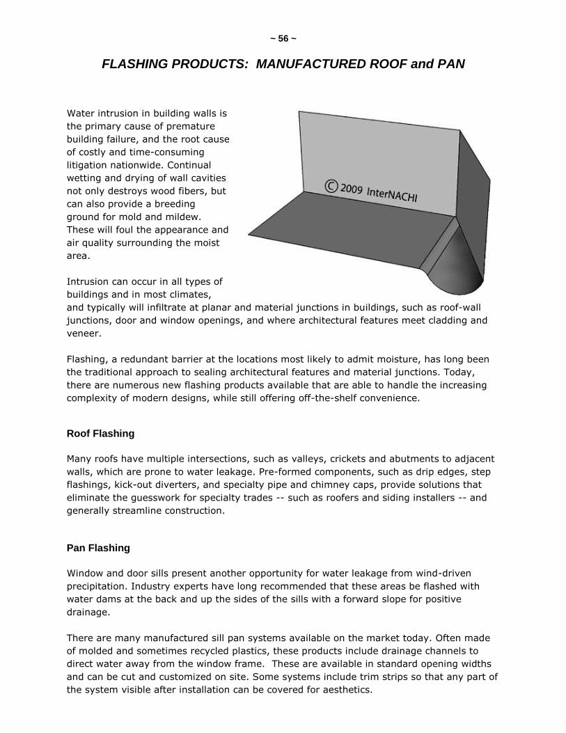
~ 56 ~
FLASHING PRODUCTS: MANUFACTURED ROOF and PAN
Water intrusion in building walls is
the primary cause of premature
building failure, and the root cause
of costly and time-consuming
litigation nationwide. Continual
wetting and drying of wall cavities
not only destroys wood fibers, but
can also provide a breeding
ground for mold and mildew.
These will foul the appearance and
air quality surrounding the moist
area.
Intrusion can occur in all types of
buildings and in most climates,
and typically will infiltrate at planar and material junctions in buildings, such as roof-wall
junctions, door and window openings, and where architectural features meet cladding and
veneer.
Flashing, a redundant barrier at the locations most likely to admit moisture, has long been
the traditional approach to sealing architectural features and material junctions. Today,
there are numerous new flashing products available that are able to handle the increasing
complexity of modern designs, while still offering off-the-shelf convenience.
Roof Flashing
Many roofs have multiple intersections, such as valleys, crickets and abutments to adjacent
walls, which are prone to water leakage. Pre-formed components, such as drip edges, step
flashings, kick-out diverters, and specialty pipe and chimney caps, provide solutions that
eliminate the guesswork for specialty trades -- such as roofers and siding installers -- and
generally streamline construction.
Pan Flashing
Window and door sills present another opportunity for water leakage from wind-driven
precipitation. Industry experts have long recommended that these areas be flashed with
water dams at the back and up the sides of the sills with a forward slope for positive
drainage.
There are many manufactured sill pan systems available on the market today. Often made
of molded and sometimes recycled plastics, these products include drainage channels to
direct water away from the window frame. These are available in standard opening widths
and can be cut and customized on site. Some systems include trim strips so that any part of
the system visible after installation can be covered for aesthetics.
~ 57 ~
QUIZ 3
1. Polyethylene flooring systems that are specially designed for use over concrete floors can alleviate __________ problems.
vibration
moisture
noise
2. ________________ is a major cause of leaking foundations.
The use of preservative-treated wood
Sandy soil
Improper drainage around the foundation
3. Frost-protected shallow foundations are protected from freezing by _________.
thermal insulation
a special chemical bonding process
installing them below the frost line
4. To be eligible for flood insurance through FEMA's National Flood Insurance Program (NFIP), _____________________.
the applicant family must qualify as low-income
the home must be located in a 100-year floodplain
the home's foundation must be constructed with certain flood damage-mitigation features
5. Traditionally, foundations are protected from frost-heaving damage by placing the footing _______ the frost line.
at
above
below
(continued)
~ 58 ~ 6. A wood foundation using preservative-treated lumber resists ________.
decay
cracking
termites
all of these
7. There is moisture in the ground from groundwater being absorbed, _____ in desert areas.
even
only
especially
except
8. _____________ are telltale signs of moisture problems in a basement.
Termites and infiltration of tree roots
Dust and spiders
Efflorescence and musty odors
9. A vapor barrier can reduce the infiltration of ____________.
moisture
all of these
radon
mold
10. When installed properly, plastic ductwork systems are watertight and airtight, and can withstand temperatures up to ______.
85° F
32° F
150° F
Answer Key is on the next page.
~ 59 ~
Answer Key to Quiz 3
1. Polyethylene flooring systems that are specially designed for use over concrete floors can alleviate moisture problems.
2. Improper drainage around the foundation is a major cause of leaking foundations.
3. Frost-protected shallow foundations are protected from freezing by thermal insulation.
4. To be eligible for flood insurance through FEMA's National Flood Insurance Program (NFIP), the home's foundation must be constructed with certain flood damage-mitigation features.
5. Traditionally, foundations are protected from frost-heaving damage by placing the footing below the frost line.
6. A wood foundation using preservative-treated lumber resists all of these.
7. There is moisture in the ground from groundwater being absorbed, even in desert areas.
8. Efflorescence and musty odors are telltale signs of moisture problems in a basement.
9. A vapor barrier can reduce the infiltration of all of these.
10. When installed properly, plastic ductwork systems are watertight and airtight, and can
withstand temperatures up to 150 F.
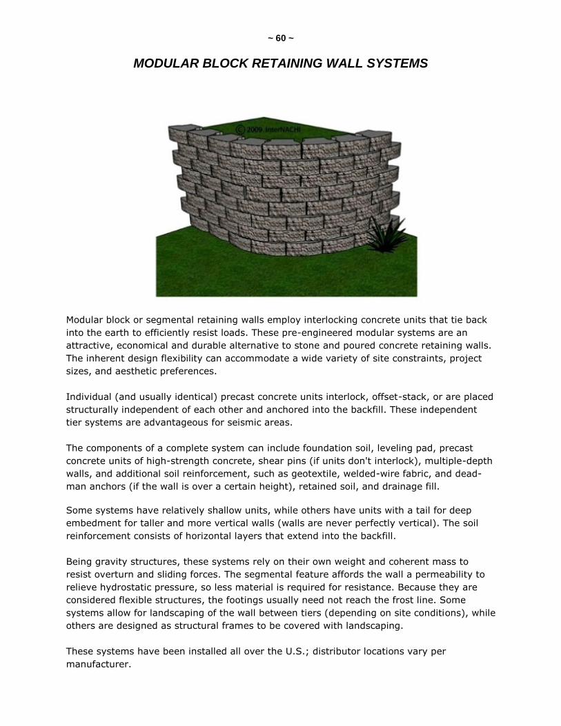
~ 60 ~
MODULAR BLOCK RETAINING WALL SYSTEMS
Modular block or segmental retaining walls employ interlocking concrete units that tie back
into the earth to efficiently resist loads. These pre-engineered modular systems are an
attractive, economical and durable alternative to stone and poured concrete retaining walls.
The inherent design flexibility can accommodate a wide variety of site constraints, project
sizes, and aesthetic preferences.
Individual (and usually identical) precast concrete units interlock, offset-stack, or are placed
structurally independent of each other and anchored into the backfill. These independent
tier systems are advantageous for seismic areas.
The components of a complete system can include foundation soil, leveling pad, precast
concrete units of high-strength concrete, shear pins (if units don't interlock), multiple-depth
walls, and additional soil reinforcement, such as geotextile, welded-wire fabric, and dead-
man anchors (if the wall is over a certain height), retained soil, and drainage fill.
Some systems have relatively shallow units, while others have units with a tail for deep
embedment for taller and more vertical walls (walls are never perfectly vertical). The soil
reinforcement consists of horizontal layers that extend into the backfill.
Being gravity structures, these systems rely on their own weight and coherent mass to
resist overturn and sliding forces. The segmental feature affords the wall a permeability to
relieve hydrostatic pressure, so less material is required for resistance. Because they are
considered flexible structures, the footings usually need not reach the frost line. Some
systems allow for landscaping of the wall between tiers (depending on site conditions), while
others are designed as structural frames to be covered with landscaping.
These systems have been installed all over the U.S.; distributor locations vary per
manufacturer.
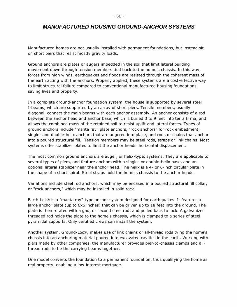
~ 61 ~
MANUFACTURED HOUSING GROUND-ANCHOR SYSTEMS
Manufactured homes are not usually installed with permanent foundations, but instead sit
on short piers that resist mostly gravity loads.
Ground anchors are plates or augers imbedded in the soil that limit lateral building
movement down through tension members tied back to the home's chassis. In this way,
forces from high winds, earthquakes and floods are resisted through the coherent mass of
the earth acting with the anchors. Properly applied, these systems are a cost-effective way
to limit structural failure compared to conventional manufactured housing foundations,
saving lives and property.
In a complete ground-anchor foundation system, the house is supported by several steel
I-beams, which are supported by an array of short piers. Tensile members, usually
diagonal, connect the main beams with each anchor assembly. An anchor consists of a rod
between the anchor head and anchor base, which is buried 3 to 9 feet into terra firma, and
allows the combined mass of the retained soil to resist uplift and lateral forces. Types of
ground anchors include "manta ray" plate anchors, "rock anchors" for rock embedment,
single- and double-helix anchors that are augered into place, and rods or chains that anchor
into a poured structural fill. Tension members may be steel rods, straps or link chains. Most
systems offer stabilizer plates to limit the anchor heads' horizontal displacement.
The most common ground anchors are auger, or helix-type, systems. They are applicable to
several types of piers, and feature anchors with a single- or double-helix base, and an
optional lateral stabilizer near the anchor head. The helix is a 4- or 6-inch circular plate in
the shape of a short spiral. Steel straps hold the home's chassis to the anchor heads.
Variations include steel rod anchors, which may be encased in a poured structural fill collar,
or "rock anchors," which may be installed in solid rock.
Earth-Lok is a "manta ray"-type anchor system designed for earthquakes. It features a
large anchor plate (up to 6x6 inches) that can be driven up to 18 feet into the ground. The
plate is then rotated with a gad, or second steel rod, and pulled back to lock. A galvanized
threaded rod holds the plate to the home's chassis, which is clamped to a series of steel
pyramidal supports. Only certified crews can install the system.
Another system, Ground-Loc, makes use of link chains or all-thread rods tying the home's
chassis into an anchoring material poured into excavated cavities in the earth. Working with
piers made by other companies, the manufacturer provides pier-to-chassis clamps and all-
thread rods to tie the carrying beams together.
One model converts the foundation to a permanent foundation, thus qualifying the home as
real property, enabling a low-interest mortgage.
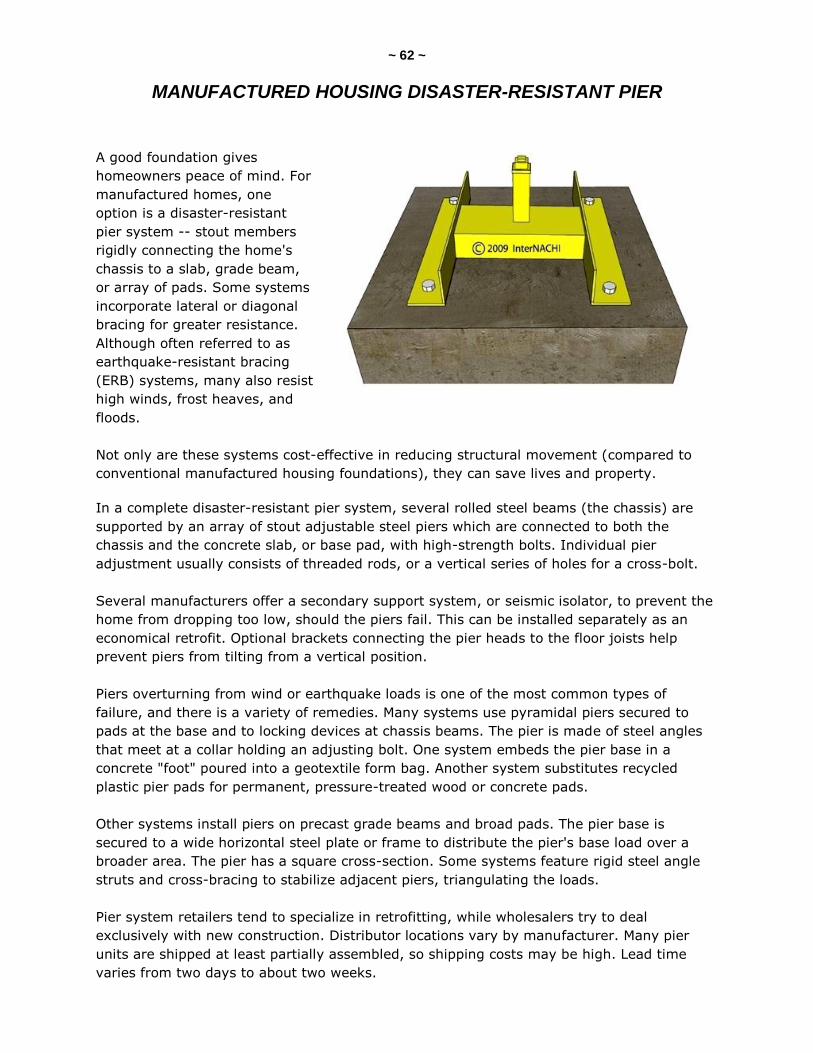
~ 62 ~
MANUFACTURED HOUSING DISASTER-RESISTANT PIER
A good foundation gives
homeowners peace of mind. For
manufactured homes, one
option is a disaster-resistant
pier system -- stout members
rigidly connecting the home's
chassis to a slab, grade beam,
or array of pads. Some systems
incorporate lateral or diagonal
bracing for greater resistance.
Although often referred to as
earthquake-resistant bracing
(ERB) systems, many also resist
high winds, frost heaves, and
floods.
Not only are these systems cost-effective in reducing structural movement (compared to
conventional manufactured housing foundations), they can save lives and property.
In a complete disaster-resistant pier system, several rolled steel beams (the chassis) are
supported by an array of stout adjustable steel piers which are connected to both the
chassis and the concrete slab, or base pad, with high-strength bolts. Individual pier
adjustment usually consists of threaded rods, or a vertical series of holes for a cross-bolt.
Several manufacturers offer a secondary support system, or seismic isolator, to prevent the
home from dropping too low, should the piers fail. This can be installed separately as an
economical retrofit. Optional brackets connecting the pier heads to the floor joists help
prevent piers from tilting from a vertical position.
Piers overturning from wind or earthquake loads is one of the most common types of
failure, and there is a variety of remedies. Many systems use pyramidal piers secured to
pads at the base and to locking devices at chassis beams. The pier is made of steel angles
that meet at a collar holding an adjusting bolt. One system embeds the pier base in a
concrete "foot" poured into a geotextile form bag. Another system substitutes recycled
plastic pier pads for permanent, pressure-treated wood or concrete pads.
Other systems install piers on precast grade beams and broad pads. The pier base is
secured to a wide horizontal steel plate or frame to distribute the pier's base load over a
broader area. The pier has a square cross-section. Some systems feature rigid steel angle
struts and cross-bracing to stabilize adjacent piers, triangulating the loads.
Pier system retailers tend to specialize in retrofitting, while wholesalers try to deal
exclusively with new construction. Distributor locations vary by manufacturer. Many pier
units are shipped at least partially assembled, so shipping costs may be high. Lead time
varies from two days to about two weeks.
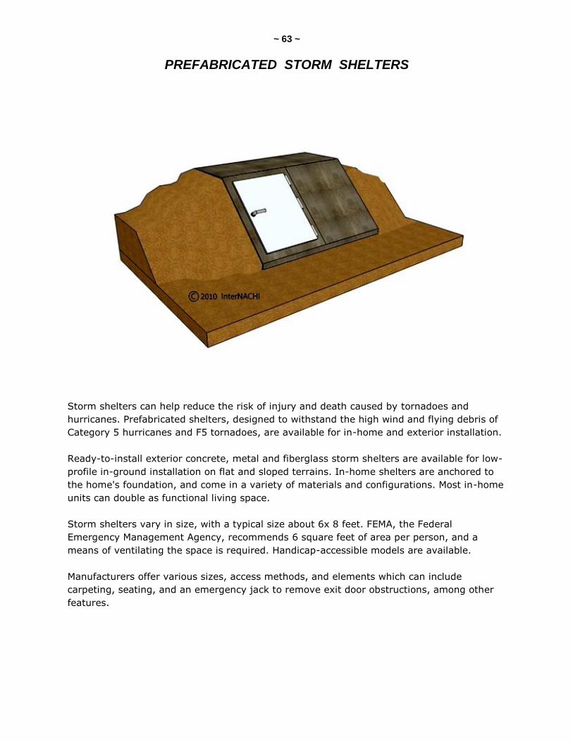
~ 63 ~
PREFABRICATED STORM SHELTERS
Storm shelters can help reduce the risk of injury and death caused by tornadoes and
hurricanes. Prefabricated shelters, designed to withstand the high wind and flying debris of
Category 5 hurricanes and F5 tornadoes, are available for in-home and exterior installation.
Ready-to-install exterior concrete, metal and fiberglass storm shelters are available for low-
profile in-ground installation on flat and sloped terrains. In-home shelters are anchored to
the home's foundation, and come in a variety of materials and configurations. Most in-home
units can double as functional living space.
Storm shelters vary in size, with a typical size about 6x 8 feet. FEMA, the Federal
Emergency Management Agency, recommends 6 square feet of area per person, and a
means of ventilating the space is required. Handicap-accessible models are available.
Manufacturers offer various sizes, access methods, and elements which can include
carpeting, seating, and an emergency jack to remove exit door obstructions, among other
features.

~ 64 ~
InspectorOutlet.com is your source for
all things inspection-related!
We are the official source for InterNACHI, the International
Association of Certified Home Inspectors (www.nachi.org).
We strive to provide the lowest prices on the highest-quality tools,
products, supplies, safety apparel and equipment, as well as educational
books, articles and marketing materials to help home and commercial
property inspectors stay on the cutting edge of the inspection industry.
"Inspector Outlet is officially endorsed by InterNACHI for the
best prices in the business for our members."
-- Nick Gromicko, Founder of InterNACHI
At InspectorOutlet.com, we are constantly expanding and adding new products, so check
our site often. If there is something you would like to see in our store, please feel free to
email us with your suggestions.
We appreciate your business,
and we’re here to help you find what you need!