inspecting & cleaning multi-fiber optical connectors
TRANSCRIPT
ZP-PKG-0462 REV 2
InsPectInG & cleanInGMultI-FIber OPtIcal cOnnectOrs
aka Ribbon, MT, MPO & MTP® Connectors
best PractIces
Process ProceduresThe fiber inspection, cleaning and testing procedures documented in this manual are recommendations made by JDSU. Please reference your company's process documents for standard tools and methods for your specific application.

Notice Every effort was made to ensure that the information in this document was accurate at the time of printing. However, information is subject to change without notice, and JDSU reserves the right to provide an addendum to this document with information not available at the time that this document was created.
copyright © Copyright 2008 JDSU, LLC. All rights reserved. JDSU, Enabling Broadband and Optical Innovation, and its logo are trademarks of JDSU, LLC. All other trademarks and registered trademarks are the property of their respective owners. No part of this guide may be reproduced or transmitted electronically or otherwise without written permission of the publisher.
trademarks JDSU is a trademark of JDSU in the United States and other countries.
CleanBlast is a registered trademark of JDSU.
RibbonDrive is a trademark of JDSU.
MTP is a registered trademark of US Conec, Ltd.
IBC is a trademark of US Conec, Ltd.
Molex is a registered trademark of Molex Incorporated.
OptiTip is a trademark of Corning Incorporated.
Specifications, terms, and conditions are subject to change without notice. All trademarks and registered trademarks are the property of their respective companies.
pateNts RibbonDrive Tips: US Patent No. 6,751,017 / 6,879,439
CleanBlast: US Patent No. 7,232.262
tested equipmeNt All pre-qualification tests were performed internally at JDSU, while all final tests were performed externally at an independent, accredited laboratory. This external testing guarantees the unerring objectivity and authoritative compliance of all test results. JDSU’s Commerce and Government Entities (CAGE) code under the North Atlantic Treaty Organization (NATO) is 0L8C3.
Fcc iNFormatioN Electronic test equipment is exempt from Part 15 compliance (FCC) in the United States.
europeaN uNioN Electronic test equipment is subject to the EMC Directive in the European Union. The EN61326 standard prescribes both emission and immunity requirements for laboratory, measurement, and control equipment. This unit has been tested and found to comply with the limits for a Class A digital device.
iNdepeNdeNt Laboratory testiNg
This unit has undergone extensive testing according to the European Union Directive and Standards.
ii

MUlTi-FibER OPTiCal COnnECTORS inSPECTiOn & ClEaning
contents
IntroductIon to FIber InspectIon INSPECT BEFORE YOU CONNECTSM............................................4Simple Solution .......................................................................................4Proactive Inspection ............................................................................4
AppendIx b: JDSU VIDEO PROBE MICROSCOPES Digital Video Probe ............................................................................18Analog Video Probe ..........................................................................18
Single-mode Connectors ..............................................................11Multimode Connectors ..................................................................11
AcceptAnce crIterIA
Bulkhead Inspection............................................................................8Patch Cord Inspection ........................................................................9
InspectInspect
Zones & Acceptance Criteria.......................................................10Grading Process ...................................................................................10
Is It cleAn? IS IT CLEAN
cLeaNbLast®: Bulkhead Cleaning .......................................12cLeaNbLast®: Patch Cord Cleaning ...................................13
ibc™ cLeaNer: Bulkhead Cleaning ......................................14ibc™ cLeaNer: Patch Cord Cleaning...................................15
cleAncleAn
Good Fiber Connection ..................................................................16Fiber Connections ..............................................................................16
connect connect
iii
sIngle Vs. MultI-FIber Single Fiber Connectors ....................................................................5Multi-fiber Connectors .......................................................................5
MultI-FIber connectors Alignment Mechanism ......................................................................6Contact Area..............................................................................................6
pAtented x- & Y-AxIs pAnnIng Knobs Panning Knobs ........................................................................................7
AppendIx A: JDSU RIBBONDRIVE™ TIPS RibbonDriveTM Inspection Tips ..................................................17Connector & Tips Guide .................................................................17
AppendIx c: JDSU CLEANBLAST® SYSTEMS Portable & Bench-top Systems ..................................................19
4 best PractIces
IntroductIon to FIber InsPectIon
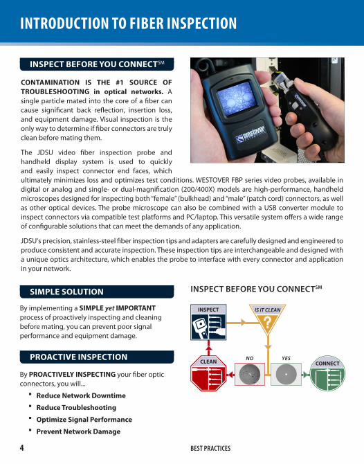
contAMInAtIon Is the #1 source oF troubleshootIng in optical networks. A single particle mated into the core of a fiber can cause significant back reflection, insertion loss, and equipment damage. Visual inspection is the only way to determine if fiber connectors are truly clean before mating them.
The JDSU video fiber inspection probe and handheld display system is used to quickly and easily inspect connector end faces, which ultimately minimizes loss and optimizes test conditions. WESTOVER FBP series video probes, available in digital or analog and single- or dual-magnification (200/400X) models are high-performance, handheld microscopes designed for inspecting both “female” (bulkhead) and “male” (patch cord) connectors, as well as other optical devices. The probe microscope can also be combined with a USB converter module to inspect connectors via compatible test platforms and PC/laptop. This versatile system offers a wide range of configurable solutions that can meet the demands of any application.
JDSU's precision, stainless-steel fiber inspection tips and adapters are carefully designed and engineered to produce consistent and accurate inspection. These inspection tips are interchangeable and designed with a unique optics architecture, which enables the probe to interface with every connector and application in your network.
Inspect beFore You connectSM
connect
IS IT CLEAN
cleAn
Inspect
YESNo
iNspect beFore you coNNectsm
By implementing a sIMple yet IMportAnt process of proactively inspecting and cleaning before mating, you can prevent poor signal performance and equipment damage.
By proActIVelY InspectIng your fiber optic connectors, you will...
reduce network downtime �reduce troubleshooting �optimize signal performance �prevent network damage �
sIMple solutIon
proActIVe InspectIon

5MUlTi-FibER OPTiCal COnnECTORS inSPECTiOn & ClEaning
sIngle FIber connectors
Also called simplex connectors, these types contain a single fiber located in the center of a ceramic zirconia ferrule. The alignment of the mated connectors/fibers is achieved inside a ceramic or bronze mating sleeve within the bulkhead adapter.
MultI-FIber connectors
A multi-fiber connector (often called "ribbon fiber connectors") contains one or more rows of fibers in a single connector to provide high-density connectivity. Alignment of the fibers is achieved when the "male" connector, which has outer pins, connects with the "female" connector, which has alignment holes (see page 6). The most common configuration is one row of 12 fibers, but standards
FibersimpLex Fiber coNNector
FerruLe
muLtipLe FibersmuLti-Fiber coNNector
sIngle Vs. MultI-FIber
exist for up to 6 rows of 12 fibers in one connector. The most common multi-fiber connector type is the MPO, also known by the brand MTP®.
Multi-fiber connectors have a larger contact area, and are therefore more susceptible to contamination. All fibers on a multi-fiber connector must be clean for it to function properly. Contamination of one fiber can cause signal degradation on other fibers. For this reason, inspection and cleaning are even more important for multi-fiber connectors.
MTP is a registered trademark of US CONEC, Ltd.
Note: Most single-mode multi-fiber connectors are APC and all multimode connectors are UPC.
sIngle FIber MultI-FIber
core
cLaddiNg
FerruLe

6 best PractIces
MultI-FIber connectors
Unlike simplex connectors, which use sleeves located inside the mating adapter body to align the two mated fibers, multi-fiber connectors are equipped with two precision metal guide pins and alignment holes that run parallel to the fibers, keeping the fibers lined up with tight tolerances.
"maLe" coNNector(w/ guide pins)
"FemaLe" coNNector(w/ alignment holes)
siNgLe Vs. muLti-Fiber coNNectors
siNgLe muLti-Fiber
aLigNmeNt Sleeve Pins & Holes
Fiber deNsity 1 4 – 72 (linear array)
size & dimeNsioNs multi-mode single Fiber 12-fiber array multi-fiber Larger Area = More Susceptible to Contamination
AlIgnMent MechAnIsM
An adapter is used to fasten the keyed architecture of both the "male" and "female" connectors securely in place.
contAct AreA
The contact area of multi-fiber connectors is observably larger than the single fiber connector, therefore making it more susceptible to contamination and higher likelihood for signal loss.
adaPter
250μm
6.4mm
2.45
mm

7MUlTi-FibER OPTiCal COnnECTORS inSPECTiOn & ClEaning
Patented X- & Y-aXIs PannIng Knobs
JDSU's patented panning knobs make the ribbondrivetM tips truly unique by allowing the user to inspect multiple fibers in a both the x- and y-axis planes.
pAnnIng Knobs
InsPectIOn tIP(bUlkhEaD inSPECTiOn)
Y-aXIs PannInG KnObadjusts vertical view of
fiber array
X-aXIs PannInG KnObadjusts horizontal view of
fiber array
FMa adaPter(PaTCh CORD inSPECTiOn)
Y-aXIs
X-aXIs
24-Fiber coNNector
The Y-AxIs pAnnIng Knob provides the industry's only solution to inspecting connectors with multiple rows of fiber. Allowing the user to easily pan up and down rows of fibers provides significant advantages in workflow and efficiency, and makes visually inspecting ALL individual fibers on the connector possible.
Y-AxIs pAnnIng Knobx-AxIs pAnnIng Knob

8 best PractIces
InsPect: bUlkhEaD Inspect
2. Insert the scope into the bulkhead to inspect.
3. Turn the Focus control on the probe to focus the fiber image on the display.
4. Turn the x- and Y-AxIs pAnnIng Knobs to view and inspect the individual fibers.
5. Determine whether cLeaN or dirty.
IF eVerY FIber In the ArrAY Is cleAn, DO NOT TOUCH IT and CONNECT.
IF eVen one FIber Is dIrtY, then cleaning is required. CLEAN.
tIp InstAllAtIon
1. Install the Fbpt-MtpA-l inspection tip to the probe microscope.
Inspect
InsPectIOn tIP (FbPT-MTPa-l)
FOcus cOntrOl
Y-aXIs PannInG KnOb
X-aXIs PannInG KnOb
Y-aXIs
X-aXIslOW-MaG VIeW

9MUlTi-FibER OPTiCal COnnECTORS inSPECTiOn & ClEaning
InsPect: PaTCh CORD Inspect
2. Insert the patch cord into the adapter.
3. Turn the Focus control on the probe to focus the fiber image on the display.
4. Turn the x- and Y-AxIs pAnnIng Knobs to view and inspect the individual fibers.
5. Determine whether cLeaN or dirty.
IF eVerY FIber In the ArrAY Is cleAn, DO NOT TOUCH IT and CONNECT.
IF eVen one FIber Is dIrtY, then cleaning is required. CLEAN.
AdApter InstAllAtIon
1. InstAll pAtch cord AdApter
A. Install the barrel assembly (Fbpp-bAp1), the universal flare adapter (Fbpt-uFMA) and the appropriate patch cord adapter (FMA-MtpA shown) to the probe.
oR
b. Install the inspection tip (Fbpt-MtpA-l shown) and the patch cord mating adapter (Fclt-Mtp-MA shown) to the probe.
InspectInsPectIOn tIP MatInG
adaPter
Patch cOrd adaPter
Flare adaPter
b. asseMblY
b
AY-aXIs PannInG KnOb
X-aXIs PannInG KnOb
A
b

10 best PractIces
Is It clean? IS IT CLEAN
A. core ZONE
b. cLaddiNg ZONEZones oVerlAYs
sIngle-Mode FIber MultIMode FIber
Ab
grAdIng process
1. Count/measure the particles/contamination that are on the fiber surface.
2. Estimate or use a grading overlay to GRADE the fiber by determining the number and size of each particle that are present in each of the 2 fiber zones.
dIrt Is eVerYwhere, and a typical dust particle (2–15μ in diameter) can significantly affect signal performance and cause permanent damage to the
Zones & AcceptAnce crIterIA
Zones are a series of concentric circles that identify areas of interest on the connector end face. The inner-most zones are more sensitive to contamination than the outer zones.
AcceptAnce crIterIA are a series of failure thresholds that define contamination limits for each zone.
fiber end face. Most field test failures can be attributed to dirty connectors, and most connectors are not inspected until the problem is detected, AFTER permanent damage has already occurred.
IF AcceptAble, DO NOT TOUCH IT and CONNECT.
IF not AcceptAble, CLEAN.

11MUlTi-FibER OPTiCal COnnECTORS inSPECTiOn & ClEaning
accePtance crIterIa
Zone nAMe (Diameter) scrAtches deFects
A. core Zone (0–25μm) none none
b. clAddIng Zone (25–115μm) no limit <= 3μmnone > 3μm
no limit < 2μm5 from 2–5μmnone > 5μm
sIngle-Mode connectors
Zone nAMe (Diameter) scrAtches deFects
A. core Zone (0–65μm) no limit <= 5μm0 > 5μm
4 <= 5μmnone > 5μm
b. clAddIng Zone (65–115μm) no limit <= 5μm0 > 5μm
no limit < 2μm5 from 2–5μmnone > 5μm
MultIMode connectors
The tables below list the AcceptAnce crIterIA standardized by the International electrotechnical commission (Iec) for single-mode and multimode connectors as documented in IEC 61300-3-35 Ed. 1.0.
IS IT CLEAN

12 best PractIces
clean: bUlkhEaD
1. Install the MTP® cleaning tip (Fclt-Mtp) to the CleanBlast® handset.
2. Insert the handset into the bulkhead, apply light pressure and push the run button to initiate cleaning.
3. Inspect the bulkhead.
4. Determine whether cLeaN or dirty.
IF cleAn, DO NOT TOUCH IT and CONNECT.
IF dIrtY, repeat CLEAN.
cleAn
cleanInG tIP(FClT-MTP)
run buttOn
cleAnblAst® - ADVANCED FIBER CLEANING SYSTEM(PortAblE)
handset
FIber InsPectIOn PrObe (OPTiONaL)
cleanInG sOlVent reFIll
6.4" tFt lcd dIsPlaY (OPTiONaL)
5' cleanInG hOse

13MUlTi-FibER OPTiCal COnnECTORS inSPECTiOn & ClEaning
clean: PaTCh CORD
1. Install the MTP® cleaning tip (Fclt-Mtp) and the patch cord mating adapter (Fclt-Mtp-MA) to the CleanBlast® handset.
2. Insert the patch cord into handset, apply light pressure and push the run button to initiate cleaning.
3. Inspect the patch cord.
4. Determine whether cLeaN or dirty.
IF cleAn, DO NOT TOUCH IT and CONNECT.
IF dIrtY, repeat CLEAN.
run buttOn
cleanInG tIP(FClT-MTP)
MatInG adaPter(FClT-MTP-Ma)
cleAn
cleAnblAst® - ADVANCED FIBER CLEANING SYSTEM(PortAblE)
handset
FIber InsPectIOn PrObe (OPTiONaL)
cleanInG sOlVent reFIll
6.4" tFt lcd dIsPlaY (OPTiONaL)
5' cleanInG hOse
14 best PractIces
cleAnclean: bUlkhEaD
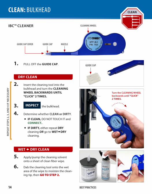
1. PULL OFF the guIde cAp.
push into bulkhead until "clIcK" 2 tIMes.
5. Apply/pump the cleaning solvent onto a sheet of clean fiber wipe.
6. Dab the cleaning tool onto the wet area of the wipe to moisten the clean-ing tip, then GO TO STEP 2.
wet drY cleAn
drY cleAn
2. Insert the cleaning tool into the bulkhead and turn the cleAnIng wheel bAcKwArds untIl "clIcK" 2 tIMes.
3. Inspect the bulkhead.
4. Determine whether cLeaN or dirty.
IF cleAn, DO NOT TOUCH IT and CONNECT.
IF dIrtY, either repeat drY cleaning oR go to wetdrY cleaning.re
peat
ste
ps 2
, 3, a
Nd
4 iF
Nec
essa
ry
ibc™ cLeaNer
GuIde caP nOZZleGuIde caP cOVer
cleanInG Wheel
GuIde caP
turn the cLeaNiNg WheeL backwards until "clIcK" 2 tIMes.

15MUlTi-FibER OPTiCal COnnECTORS inSPECTiOn & ClEaning
clean: PaTCh CORD
5. Apply/pump the cleaning solvent onto a sheet of clean fiber wipe.
6. Wipe the end of the fiber connector on the wet area of the wipe, then GO TO STEP 2.
wet drY cleAn
1. Carefully PULL OUT the guIde cAp coVer.
drY cleAn
2. Insert the patch cord into the cleaning tool, apply slight pressure and turn the cleAnIng wheel bAcKwArds untIl "clIcK" 2 tIMes.
3. Inspect the patch cord.
4. Determine whether cLeaN or dirty.
IF cleAn, DO NOT TOUCH IT and CONNECT.
IF dIrtY, either repeat drY cleaning oR proceed to wetdrY cleaning.
repe
at s
teps
2, 3
, aN
d 4
iF
Nec
essa
ry
cleAn
GuIde caP cOVer
turn the cLeaNiNg WheeL backwards until "clIcK"
2 tIMes.
ibc™ cLeaNer
GuIde caP nOZZleGuIde caP cOVer
cleanInG Wheel

16 best PractIces
connect connect
CLEAN CONNECTIONCORECLADDING
Light Transmitted
There are 3 bAsIc prIncIples that are critical to achieving an efficient fiber optic connection:
1. perFect core AlIgnMent
2. phYsIcAl contAct
3. prIstIne connector InterFAce
good FIber connectIon
FIber connectIons
Today’s connector design and production techniques have eliminated most of the challenges to achieving core AlIgnMent and phYsIcAl contAct.
What remains challenging is maintaining a prIstIne end FAce. As a result, contAMInAtIon Is the #1 source oF troubleshootIng in optical networks.
Optical connections are made for one of two reasons:
1. coMpletIng A sYsteM lIght pAth (tx to rx)
Connectors are used extensively throughout optical networks. They give us the ability to reconfigure the network and provision services. If contamination is present in the light path, system performance will be degraded.
Always Inspect and, if necessary, cleAn the optical port and optical cable for contamination before connecting.
2. connectIng A test deVIce to pArt oF the sYsteM
Test devices are frequently connected and disconnected to elements of the network. Often, test leads are systematically connected to each port in a network element in sequence. This duty cycle makes test leads especially prone to contamination and damage. If a test lead is contaminated, it can quickly spread that contamination through a large portion of the network.
Always Inspect and, if necessary, cleAn the network port and test lead for contamination before connecting.

17MUlTi-FibER OPTiCal COnnECTORS inSPECTiOn & ClEaning
aPPendIX a: JDSU RibbOnDRiVETM TiPS
rIbbondrIVeTM tIps
JDSU's patented rIbbondrIVe™ tips are specialty tips that allow inspection of high-density, multi-fiber array connectors that are mounted within a bulkhead adapter. Each tip mates securely with connectors using a precision-keyed mating adapter interface. The patented “panning knobs” allow the user to view each fiber individually in both the X- and Y-AXIS.
Note: Additional multi-fiber (ribbonDrivetM) inspection tips are available for other types of connectors (e.g., MPX, Mt ferrule, HbMt, oGI, Molex, SMC, etc.).
connector tYpe InspectIon tIp ApplIcAtIon
MtP®/uPc FbPt-MtP inspects MtP®/uPc connector through a bulkhead (female interface).
FbPt-MtP-a6 inspects MtP®/uPc connector through a bulkhead (female interface) - 60° angle.
MtP®/aPc FbPt-MtPa inspects MtP®/aPc connector through a bulkhead (female interface).
FbPt-MtPa-l inspects MtP®/aPc connector through a bulkhead (female interface) - long reacH w/ Y-aXIs panning knob.
MOleX® ar8
FbPt-ar8-24FbPt-ar8G
The FbPT-aR8-24 tip & aR8g guide allow inspection of MoleX® ar8 array connectors (plug and receptacle) w/ Y-aXIs panning knob..
OPtItIP® FbPt-cOd-Mt inspects oPtItIP® flat-polish connector (plug and receptacle).
FbPt-cOd-Mta inspects oPtItIP® angle-polish connector (plug and receptacle).
FMa adapter & Flare adapter FMa-MtPa &FbPt-uFMa
inspects MtP® patch cords (male interface).
Mating adapter Fclt-MtP-Ma Mating adapter for inspecting MtP® patch cords (male interface).

18 best PractIces
USB 2.0 connection to PC/laptop
with HD Series displays
with USB converter module
JDSU's westoVer p5000 digital probe microscope connects directly to PC/laptops via a USB 2.0 connection, and operates with FIbercheK2tM, an advanced software that determines the acceptability of optical fiber end faces through advanced automated inspection and analysis.
dIgItAl VIdeo probe
JDSU's westoVer Fbp and Fbe analog probe microscopes connect directly to westoVer hd dIsplAYs (HD1, HD2 or HD3) or to a PC/laptop or JDSU test platform (t-bErD/MtS or FSt) via a usb AnAlog to dIgItAl conVerter.
AnAlog VIdeo probe
aPPendIX b: JDSU WESTOVER ViDEO PRObE inSPECTiOn
19MUlTi-FibER OPTiCal COnnECTORS inSPECTiOn & ClEaning
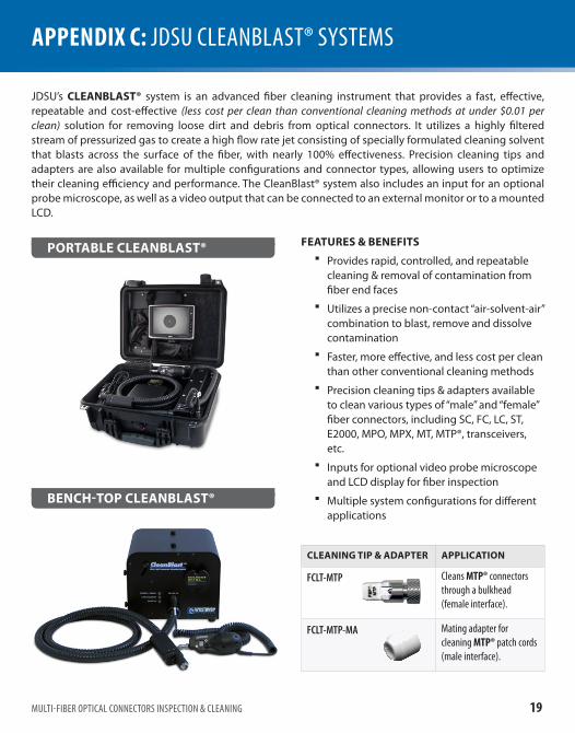
portAble cleAnblAst®
bench-top cleAnblAst®
aPPendIX c: JDSU ClEanblaST® SySTEMS
JDSU’s cleAnblAst® system is an advanced fiber cleaning instrument that provides a fast, effective, repeatable and cost-effective (less cost per clean than conventional cleaning methods at under $0.01 per clean) solution for removing loose dirt and debris from optical connectors. It utilizes a highly filtered stream of pressurized gas to create a high flow rate jet consisting of specially formulated cleaning solvent that blasts across the surface of the fiber, with nearly 100% effectiveness. Precision cleaning tips and adapters are also available for multiple configurations and connector types, allowing users to optimize their cleaning efficiency and performance. The CleanBlast® system also includes an input for an optional probe microscope, as well as a video output that can be connected to an external monitor or to a mounted LCD.
FeAtures & beneFIts
Provides rapid, controlled, and repeatable �cleaning & removal of contamination from fiber end faces
Utilizes a precise non-contact “air-solvent-air” �combination to blast, remove and dissolve contamination
Faster, more effective, and less cost per clean �than other conventional cleaning methods
Precision cleaning tips & adapters available �to clean various types of “male” and “female” fiber connectors, including SC, FC, LC, ST, E2000, MPO, MPX, MT, MTP®, transceivers, etc.
Inputs for optional video probe microscope �and LCD display for fiber inspection
Multiple system configurations for different �applications
cleAnIng tIp & AdApter ApplIcAtIon
Fclt-MtP Cleans MtP® connectors through a bulkhead (female interface).
Fclt-MtP-Ma Mating adapter for cleaning MtP® patch cords (male interface).

north AMerIcATEL: 1 866 228 3762FAX: 1 301 353 9216
lAtIn AMerIcATEL: +55 11 5503 3800FAX: +55 11 5505 1598
AsIA pAcIFIcTEL: +852 2892 0990FAX: +852 2892 0770
eMeATEL: +49 7121 86 2222FAX: +49 7181 86 1222
www.jdsu.com/inspect
All statements, technical information and recommendations related to the products herein are based upon information believed to be reliable or accurate. However, the accuracy or completeness thereof is not guaran-teed, and no responsibility is assumed for any inaccuracies. The user assumes all risks and liability whatsoever in connection with the use of a product or its applications. JDSU reserves the right to change at any time without notice the design, specifications, function, fit or form of its products described herein, including withdrawal at any time of a product offered for sale herein. JDSU makes no representations that the products herein are free from any intellectual property claims of others. Please contact JDSU for more information. JDSU and the JDSU logo are trademarks of JDS Uniphase Corporation. Other trademarks are the property of their respective holders. © 2008 JDS Uniphase Corporation. All rights reserved.test and measurement regional sales
ZP-PKG-0462REV 2