insights from the interchange safety analysis tool ... · wolpert and coakley 1 1 insights from the...
TRANSCRIPT
Wolpert and Coakley 1
Insights from the Interchange Safety Analysis Tool-Enhanced (ISATe) 1
Methodology on Freeway and Interchange Design Policy 2
3
Andrew Wolpert, P.E. 4 CH2M HILL 5 1103 Schrock Road 6 Suite 400 7 Columbus, OH 43229 8 (614) 825-6763 9 [email protected] 10 11 Richard C. Coakley, P.E., PTOE 12 CH2M HILL 13 135 South 84th Street 14 Suite 400 15 Milwaukee, WI 53214 16 (414) 847-0423 17 [email protected] 18 19 20 21 Word count: 167 words abstract + 3,750 words text + 15 tables/figures x 250 words (each) = 7,382 words 22 23

Wolpert and Coakley 2
ABSTRACT 1
NCHRP Project 17-45: Safety Prediction Methodology and Analysis Tool for Freeways and Interchanges 2 conducted by the Texas Transportation Institute with CH2M HILL produced the predictive method for the 3 AASHTO Highway Safety Manual for freeways and interchanges. The method employs virtually all 4 important geometric variables (excluding vertical alignment) and many important traffic variables in 5 predicting crash frequency and severity. The Interchange Safety Analysis Tool – Enhanced (ISATe) was 6 developed and enables prediction of the safety performance of interchanges, including mainline segments, 7 ramp segments, and ramp terminal intersections. 8 9 CH2M HILL has applied the Highway Safety Manual methodologies to evaluate and compare the 10 expected safety performance for several projects. In applying ISATe a number of interesting findings 11 emerged. In this paper, we will present the results of safety analyses performed by CH2M HILL on the 12 safety effects and trade-offs associated with interchange configurations, cross section options, horizontal 13 sight distance variations, and horizontal geometry revisions. Safety performance for project case studies 14 for the Ohio Department of Transportation’s I-270/US 33 interchange and the Wisconsin Department of 15 Transportation’s I-94 East/West Corridor will be reviewed. 16 17 18

Wolpert and Coakley 3
INTRODUCTION 1 The Interchange Safety Analysis Tool-Enhanced (ISATe) provides information about the relationship 2 between roadway horizontal geometry, cross section elements, roadside barriers and safety. It is based on 3 research that quantified the relationship between various design elements and average crash frequency. 4 The information provided in ISATe is intended to help designers use engineering judgment about the 5 safety performance of design alternatives. ISATe automates a safety prediction method that consists of 6 various algorithms and equations. Using ISATe requires the designer to divide the study area into 7 homogeneous segments in order for the tool to provide the best results. Segmentation is primarily based 8 on cross section dimensions. 9
Using ISATe, CH2M HILL analyzed safety performance interchange alternatives in Ohio and Wisconsin. 10 CH2M HILL analyzed a comprehensive list of criteria for evaluating traffic operations (level of service, 11 delay), design and construction requirements, right-of-way needs, capital costs, environmental and 12 community impacts and their mitigation, and safety performance. ISATe enables prediction of the safety 13 performance of interchanges, including mainline, ramps and ramp terminal intersections. 14
CASE STUDY: I-270/US 33 INTERCHANGE IMPROVEMENTS – DUBLIN, OHIO 15 Background and Project Description 16 The Ohio Department of Transportation (ODOT) is reconstructing the I-270 / US 33 interchange to 17 accommodate existing and projected traffic volumes. Completed in 1973, the I-270 outerbelt has carried 18 an ever-increasing amount of traffic, particularly as the suburbs around Columbus have grown. Rapid 19 population and employment growth in the vicinity of the I-270/US 33 interchange has resulted in 20 dramatic increases in vehicle travel. Daily traffic volumes on I-270 have doubled and volumes on US 33 21 have also increased substantially. The existing interchange is a cloverleaf configuration. The I-270/US 33 22 interchange is unique in that it operates as a system interchange to the west, but as a service interchange 23 to the east as it approaches the Frantz Road/Post Road intersection. Traveling west of the Frantz 24 Road/Post Road intersection toward the Avery-Muirfield Drive interchange, US 33 operates as a limited 25 access facility. 26
ODOT initiated this improvement project by identifying alternative interchange configurations. 27 Elements of the project purpose and need were used in the development and evaluation of alternatives, 28 including the no-build alternative. This was accomplished by creating specific measurable criteria to 29 define how well alternatives satisfy the purpose and need elements. 30
In total, eight conceptual 31 alternatives were developed. From 32 the initial concepts, the three 33 alternatives shown in Figure 2 34 (Alternatives 4, 7, and 8) were 35 identified as best meeting the 36 project purpose and need. These 37 three interchange alternatives were 38 further developed and refined to 39 provide a phased construction 40 approach to meet the project’s goals 41 and funding constraints. The 42 refinements helped to facilitate the 43 evaluation and comparison effort to 44 select the preferred alternative. 45 FIGURE 1 I-270/US 33 Project Area.

Wolpert and Coakley 4
Alternative 4 Alternative 7 1
Alternative 8 2
3
These three interchange alternatives for I-270/US 33 were further developed to meet forecast traffic 4 demands for the year 2035. Each alternative was designed in accordance with the ODOT Location and 5 Design Manual and American Association of State Highway and Transportation Officials (AASHTO) 6 Policy on Geometric Design, with the same design criteria applied to each. During the preferred 7 alternative development process, a comprehensive list of criteria including traffic operations (level of 8 service, delay), design and construction requirements, right-of-way needs, capital costs, environmental 9 and community impacts and their mitigation, and safety performance were analyzed for each alternative. 10 Thus, predicted safety performance was one of many criteria considered in the selection of the preferred 11 alternative. 12
The final design stage of the I-270/US 33 interchange was completed in August 2014 with 13 construction commencing in March 2015. 14 15 Project Purpose and Need 16 The following elements, identified through the evaluation of existing transportation facilities, the social 17 and economic conditions of the project area, consultation with affected communities, input from public 18 meetings and the business community, and input from environmental review agencies, defined the 19 purpose and need associated with the I-270/US-33 Interchange: 20
Address the current and future traffic congestion; 21 Resolve existing obsolete geometric designs; and, 22 Improve safety 23
FIGURE 2 I-270/US 33 Alternatives Selected for Detailed Evaluation

Wolpert and Coakley 5
Safety Performance Analysis 1 ODOT applied the Alternative Analysis with Predictive Models safety analysis tool using the Federal 2 Highway Administration (FHWA) Interchange Safety Analysis Tool – Enhanced (ISATe) to evaluate and 3 compare the expected safety performance of the three alternative configurations. In addition, ODOT used 4 ISATe to compare expected safety performance for an isolated loop ramp radius during the investigation 5 of possible value engineering options. ISATe enables prediction of the safety performance of 6 interchanges (including mainline segments, ramp segments and ramp terminal intersections) and is the 7 adopted procedure for predictive safety performance of freeways and interchanges per the AASHTO 8 Highway Safety Manual crash prediction methods. 9
The I-270/US 33 safety performance evaluation focused on predicting the number of KAB (K is a 10 fatal crash, A is an incapacitating injury crash, and B is a non-incapacitating injury crash) crashes to be 11 expected for each alternative between 2015 and 2035. The societal costs associated with the number of 12 predicted crashes over the study period were calculated to use in the evaluation of the alternatives. 13
The ISATe model was not calibrated for Ohio at the time of use. The use of an uncalibrated 14 model is acceptable and still provides useful insights. The results were used to conduct order of 15 magnitude estimates for each of the three alternative configurations. When assessing the model results, 16 the project team suspected the ISATe was over-predicting possible injury and property damage crashes. 17 The reliability of severe (KAB) crash reporting is generally known in the industry to be greater than that 18 for property damage and lower level injury crash types given that there are typically fewer differences in 19 reporting thresholds related to severe injury and fatal crash types. In recognition of this uncertainty, the 20 crash predictions for the property damage and possible injury crashes were not included in the evaluation 21 for the alternatives; alternative analysis was focused on the more reliable fatal and serious injury crashes. 22
Interchange/Freeway Alternative Evaluation Results 23 Table 1 summarizes the KAB crashes predicted by the ISATe model and the associated societal cost for 24 each alternative. 25 26
KAB Crashes Societal Costs
No-Build 308 $97M
Alternative 4 325 $91M
Alternative 7 409 $109M
Alternative 8 320 $89M
TABLE 1 Predicted Crash Frequencies and Societal Costs (2015-2035). 27
The ISATe analysis predicted the fewest crashes for the No Build condition during the study period, 28 followed by Alternative 8, Alternative 4, and Alternative 7, respectively. Further analysis of the 29 predictive model results determined that there are trade-offs when reconfiguring interchanges with high 30 speed ramp designs. One trade-off for a ‘higher quality’ design is the increased amount of vehicle miles 31 traveled through the interchange by means of a greater total mileage within the interchange due to high 32 speed flyover ramps replacing small radii loop ramps. Also, with higher speeds come reduced margins 33 for driving errors despite the fact that design standards for freeway elements are typically related to 34 design speeds. The Vehicle Miles Traveled (VMT) for Alternatives 4, 7 and 8 were more than 30 percent 35 greater than the existing configuration, which in turn would be expected to result in higher crash 36 frequencies than the No Build given the larger area of exposure. Alternatives 4 and 8 were predicted to 37 have fewer KA type crashes than the No-Build and Alternative 7, which reduced the overall societal cost 38 for these two alternatives. Of the three design alternatives, the modeling predicted Alternative 8 would 39 have the lowest KAB crash frequency. Subsequent calculations also suggested this alternative would have 40 the lowest expected societal cost. 41

Wolpert and Coakley 6
The team analyzed a comprehensive list of criteria for evaluating traffic operations (level of 1 service, delay), design and construction requirements, right-of-way needs, capital costs, environmental 2 and community impacts and their mitigation, and safety performance. Based on the evaluation criteria, 3 the benefits and trade-offs of each alternative were determined. In collaboration with the City of Dublin, 4 ODOT selected Alternative 8 as the preferred alternative based on the evaluation of all criteria. 5 6 Loop Ramp Evaluation 7 After the selection of Alternative 8, the team began optimizing the design and investigating ways to 8 reduce construction costs and right-of-way impacts and still meet the Purpose & Need elements. Figure 9 3 shows the Phase 1 and Phase 2 construction sequencing. The Phase 1 construction removes the loop 10 ramps in the northwest and southeast quadrants; therefore, eliminating all the weaving movements created 11 by the cloverleaf design. The Phase 2 project will consist of constructing a directional flyover ramp from 12 Northbound I-270 to Westbound US 33. This construction will occur in 10 – 20 years when the loop 13 ramp in the northeast quadrant (Ramp SW) is estimated to be over capacity. Because a phased 14 construction approach was needed to meet the project’s funding constraints, additional construction and 15 right-of-way costs were associated with Phase 1 due to the existing loop Ramp SW, because ramps need 16 to be constructed outside the loop ramp. Cut walls adding millions in construction, along with greater 17 right-of-way impacts, are required if the existing loop ramp was to remain in its current condition. The 18 existing loop Ramp SW meets a design speed of 30 mph with an 8% pavement cross slope and has 19 advanced warning signs for 25 mph. The existing lane width is 16’. The existing right and left shoulder 20 widths are 6’ and 3’, respectively. 21
22
23 FIGURE 3 Alternative 8 Phased Construction Sequence 24
For the interim condition (between Phase 1 and Phase 2 construction) three different options were 25 developed and evaluated from a safety and cost perspective. 26
Phase 2 Construction
(in 10-20 years)
Remove Loop
Ramp SW in
Phase 2
Retaining Walls
from Phase 1

Wolpert and Coakley 7
Option 1 – Maintain existing Ramp SW with a 230’ radius 1 Option 2 – Reconstruct Ramp SW with a 200’ radius (construction cost savings ~ $2M) 2 Option 3 – Reconstruct Ramp SW with a 185’ radius (construction cost savings ~ $5M) 3 CH2M HILL reviewed the design of each option to determine if there was a difference in substantive 4
(actual) safety performance. The Mitigation Strategies for Design Exceptions recommends the following 5 resources to quantify safety and support decision making: the Interactive Highway Safety Design Model 6 (IHSDM), The Highway Safety Manual, and the AASHTO Guide for Achieving Flexibility in Highway 7 Design. Using the Highway Safety Manual crash prediction methods in ISATe, the total predicted 8 crashes for each option over a 10-year period from 2015 to 2025 were calculated. Table 2 provides the 9 number of severe crash types KAB for substantive safety comparisons. 10
Radius
(ft)
Equivalent
Design
Speed (mph)
Crash type:
K
Crash Type:
A
Crash Type:
B
2015-2025
Total KAB
Crashes
Option 1 230 30 0.4 1.1 7.1 9
Option 2 200 27 0.4 1.2 7.7 10
Option 3 185 26 0.4 1.3 8.2 10
TABLE 2 Predicted Crash Frequencies (2015-2025). 11
Using an uncalibrated ISATe model, the team found very little difference in the safety 12 performance between each option. Minor changes to the radii and design speeds did not have a 13 significant impact on the number of predicted crashes during the study period. From HSM work in Ohio, 14 the fatal/injury (KAB) crashes are very close to model predictions and it would be primarily the PDO’s 15 that one might expect to see any noticeable difference as a result of calibration. Weighing the predicted 16 safety performance results versus possible negative public reaction to reducing the Ramp SW radius was 17 as issue during the evaluation process. The project team determined that not reducing existing loop Ramp 18 SW in Phase 1 construction was the most appropriate resolution. 19 20 21 22
23 CASE STUDY: I-94 EAST/WEST CORRIDOR – MILWAUKEE, WISCONSIN 24 25 Background and Project Description 26 The I-94 East-West freeway was constructed in the early 1960s and is one of the busiest routes in 27 southeastern Wisconsin. It serves a vital link to downtown Milwaukee and the western suburbs, and is 28 part of a major east-west Interstate route serving national, regional, and local traffic for trips within and 29 through the study area. A key project constraint is existing cemeteries at the west leg of the project. The 30 Wisconsin Department of Transportation (WisDOT) has made a commitment not to move graves for this 31 project. 32
The scope of the proposed action includes rebuilding the freeway, bridges, and interchanges; 33 reconstructing the Stadium Interchange as a hybrid between a system and service interchange; removing 34 the Mitchell Boulevard Interchange and replacing it with a service interchange located within the Stadium 35 Interchange; potentially removing the Hawley Road interchange, providing freeway access at Hawley 36 Road only to and from the west, or keeping a full access at the Hawley Road interchange; potentially 37 constructing a double deck structure between Hawley Road and Mitchell Boulevard to avoid impacts to 38 existing cemeteries; and, enhancing the aesthetic appearance of the reconstructed freeway. 39

Wolpert and Coakley 8
Alternatives 1 Through the alternatives screening process, the following four alternatives were retained for detailed 2 study for the I-94 East-West Corridor: 3
West segment (70th Street to Stadium Interchange) 4 o Add a 4th lane in each direction, with either no Hawley Road Interchange or a half-5
interchange at Hawley Road (on-/off-ramps to and from the west), and narrow lanes and 6 shoulders through cemetery area (At-Grade alternative) 7
o Add a 4th lane in each direction, with Hawley Road Interchange and double deck (all up 8 or partially down) through cemetery area (Double Deck alternative) 9
East segment (Stadium Interchange to 16th Street) 10 o Add a 4th lane in each direction, with a modified single-point interchange at the Stadium 11
Interchange and remaining nearly on-alignment east of 32nd Street (On-Alignment 12 alternative) 13
o Add a 4th lane in each direction, with a modified single-point interchange at the Stadium 14 Interchange and an off-alignment segment east of 32nd Street (Off-Alignment 15 alternative) 16
No-build (Replace in Kind) 17 All of these alternatives are interchangeable. For example, both the On-Alignment and Off-Alignment 18 alternatives in the east segment are compatible with the Double Deck alternative in the west segment. The 19 same holds true for the At-grade alternative. 20
21 West Segment 22 The west segment of the study area is I-94 from 70th Street to Yount Drive, just west of the Stadium 23 Interchange. This segment includes the existing 68th/70th Street, Hawley Road, and Mitchell Boulevard 24 service interchanges. All alternatives were developed to avoid a direct impact on the cemeteries (Beth 25 Hamedrosh Hagodel Cemetery, Spring Hill Cemetery, and Wood National Cemetery) adjacent to I-94. 26 27 At-Grade Alternative 28 The At-Grade alternative would reconstruct I-94 to 8 travel lanes (4 in each direction) at the same 29 elevation as the existing freeway. To avoid encroachments to the cemeteries, the reconstructed freeway 30 mainline would have less than 12-foot driving lanes and narrow shoulders in the approximate 2,000-foot 31 segment between the adjacent cemeteries. The lanes would transition from 12 feet to 11 feet for several 32 hundred feet east and west of the 11-foot-lane segment. The shoulder widths would vary in this segment 33 as the available right-of-way varies (the shoulders would be as narrow as 2 feet). East and west of the 34 cemeteries, the freeway would have standard 12-foot lanes and full shoulders. 35 36

Wolpert and Coakley 9
1
FIGURE 4 West Segment – At-Grade Alternative 2 3 The 68th/70th Street interchange would be reconstructed in its current configuration (a split diamond 4 interchange). Entrance and exit ramps would be longer than the existing ramps to provide more room for 5 traffic entering and exiting the freeway, improving safety and traffic operations. 6
The At-Grade alternative would have either no interchange at Hawley Road or a half interchange 7 at Hawley Road. The half interchange would have an entrance ramp to westbound I-94 and an exit ramp 8 from eastbound I-94 to Hawley Road. There would be no westbound exit ramp or eastbound entrance 9 ramp as part of the half interchange at Hawley Road option. The reason for no interchange or a half 10 interchange is that any ramps east of Hawley Road would impact the cemeteries and result in the 11 relocation of graves. 12
The freeway entrance and exit ramps at the Mitchell Boulevard interchange would be removed. 13 Having entrance and exit ramps in the narrow cemetery area would increase congestion and there is no 14 space for the ramps without impacting the cemeteries or having very short and unsafe merge distances on 15 the interstate. The Mitchell Boulevard interchange would be replaced by a new local road interchange 16 under the Stadium Interchange. 17 18 Double Deck Alternative 19 The Double Deck alternative would reconstruct I-94 to 8 travel lanes (4 in each direction). A Double 20 Deck, meaning the freeway lanes would be stacked with one set of freeway lanes elevated over the other, 21 would be constructed in the area between the cemeteries to avoid direct impacts to the cemeteries. The 22 transition back to side-by-side freeway lanes would occur at about 64th Street, just west of the Hawley 23 Road interchange and Yount Drive, just west of the Stadium Interchange. 24
All I-94 lanes would be 12-feet-wide under this alternative. The shoulder widths will vary in this 25 segment as the available right‐of‐way varies near the cemeteries where the shoulder would be 10 feet. 26 East and west of the cemeteries, the freeway would have standard 12‐foot lanes and full shoulders. The 27 10-foot shoulders balance the safety needs of the project with the consideration of impacts to the 28 cemeteries. 29
This alternative would reconstruct the 68th/70th Street and Hawley Road interchanges with 30 collector-distributor roads connecting the interchanges. Collector-distributor roads would eliminate 31 weaving on I-94 between 68th Street and Hawley Road. The 68th/70th Street and Hawley Road 32

Wolpert and Coakley 10
interchanges would be reconstructed with a configuration similar to that of the existing interchanges. 1 Ramps at the Mitchell Boulevard interchange would be removed and replaced by a new interchange 2 imbedded within the Stadium Interchange. 3 4
5
FIGURE 5 West Segment – Double Deck Alternative 6
7 East Segment 8 The east segment of the study area is from Yount Drive, just west of the Stadium Interchange, to 16th 9 Street. This segment includes the existing 35th Street and 25th/26th/28th Street service interchanges 10 and the Stadium Interchange. The alternatives retained for detailed evaluation include a new embedded 11 interchange under the Stadium Interchange to replace the interchange removed from 12 Mitchell Boulevard. 13

Wolpert and Coakley 11
1
FIGURE 6 East Segment – Stadium Interchange Alternative 2 3 Off-Alignment Alternative 4 Under the Off-alignment alternative, the Stadium Interchange would be reconstructed as shown in Figure 5 6. The interchange would function as a hybrid between a service interchange and a system interchange. 6 Some of the ramps would be free-flow and some would be controlled by a traffic signal. All of the exit 7 ramps from I-94 to US 41/Miller Park Way would be free-flow ramps, meaning no traffic signals for 8 those movements. 9 10
11
FIGURE 7 East Segment – Off Alignment Alternative 12

Wolpert and Coakley 12
Underneath the Stadium Interchange, new on- and off-ramps to 44th Street and a new local street, 1 tentatively referred to as 46th Street, would be constructed. The ramps would replace the interchange that 2 would be removed at Mitchell Boulevard. 3
East of the Stadium Interchange, the 35th Street interchange would be reconstructed. Braided 4 ramps between the Stadium Interchange and the 35th Street interchange would allow the two closely 5 spaced interchanges to operate safely. Braided ramps would also be provided between the 35th and 27th 6 Street interchanges. 7
East of 32nd Street, I-94 would be reconstructed about 400 feet south of its current alignment. I-94 8 would rejoin its existing alignment near 18th Street. The I-94 Off-Alignment alternative would remove 9 the horizontal and vertical curves (i.e. downhill with a curve at the bottom) on I-94 near 25th Street that 10 limit sight distance for eastbound I-94 drivers as they approach the Marquette interchange. This would 11 decrease the crash frequency on this segment of I-94 by 38 percent compared to the existing freeway, and 12 2 percent compared to the On-Alignment alternative. 13
The Off-Alignment alternative also provides space to build on- and off-ramps directly to 27th Street. 14 This would provide a more direct connection between I-94 and 27th Street, a major north-south arterial 15 and state highway. 16 17 On-Alignment Alternative 18 The On-Alignment alternative would have essentially the same Stadium interchange as the Off-Alignment 19 alternative, as shown in Figure 5. The difference between the two alternatives is that east of 32nd Street, 20 the freeway would remain close to its current alignment and be widened to the south. The centerline of 21 reconstructed I-94 would be about 50 feet south of the existing freeway centerline. This alternative would 22 improve sight distance compared to the existing freeway, but not to the extent of the Off-Alignment 23 alternative. 24 25
26
FIGURE 8 East Segment – On Alignment Alternative 27 28 The intersection of 27th Street and St. Paul Avenue would need more extensive reconstruction under this 29 alternative than the Off-Alignment alternative. This is because most of the exiting freeway traffic destined 30 for 27th Street would first get to St. Paul Avenue at 25th or 26th Street, and then turn onto 27th Street at its 31 intersection with St. Paul Avenue. Similarly, most of the traffic entering the freeway at 25th and 28th 32 Streets would also use the 27th/St. Paul intersection. 33
Wolpert and Coakley 13
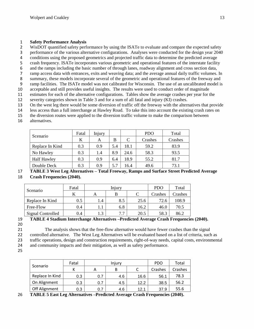
Safety Performance Analysis 1 WisDOT quantified safety performance by using the ISATe to evaluate and compare the expected safety 2 performance of the various alternative configurations. Analyses were conducted for the design year 2040 3 conditions using the proposed geometrics and projected traffic data to determine the predicted average 4 crash frequency. ISATe incorporates various geometric and operational features of the interstate facility 5 and the ramps including the basic number of through lanes, roadway alignment and cross section data, 6 ramp access data with entrances, exits and weaving data; and the average annual daily traffic volumes. In 7 summary, these models incorporate several of the geometric and operational features of the freeway and 8 ramp facilities. The ISATe model was not calibrated for Wisconsin. The use of an uncalibrated model is 9 acceptable and still provides useful insights. The results were used to conduct order of magnitude 10 estimates for each of the alternative configurations. Tables show the average crashes per year for the 11 severity categories shown in Table 3 and for a sum of all fatal and injury (KI) crashes. 12 On the west leg there would be some diversion of traffic off the freeway with the alternatives that provide 13 less access than a full interchange at Hawley Road. To take this into account the existing crash rates on 14 the diversion routes were applied to the diversion traffic volume to make the comparison between 15 alternatives. 16
Scenario Fatal Injury PDO Total
K A B C Crashes Crashes
Replace In Kind 0.3 0.9 5.4 18.1 59.2 83.9
No Hawley 0.3 1.4 8.9 24.6 58.3 93.5
Half Hawley 0.3 0.9 6.4 18.9 55.2 81.7
Double Deck 0.3 0.9 5.7 16.4 49.6 73.1
TABLE 3 West Leg Alternatives – Total Freeway, Ramps and Surface Street Predicted Average 17
Crash Frequencies (2040). 18
Scenario Fatal Injury PDO Total
K A B C Crashes Crashes
Replace In Kind 0.5 1.4 8.5 25.6 72.6 108.9
Free-Flow 0.4 1.1 6.8 16.2 46.0 70.5
Signal Controlled 0.4 1.3 7.7 20.5 58.3 86.2
TABLE 4 Stadium Interchange Alternatives –Predicted Average Crash Frequencies (2040). 19 20
The analysis shows that the free-flow alternative would have fewer crashes than the signal 21 controlled alternative. The West Leg Alternatives will be evaluated based on a list of criteria, such as 22 traffic operations, design and construction requirements, right-of-way needs, capital costs, environmental 23 and community impacts and their mitigation, as well as safety performance. 24
25
Scenario Fatal Injury PDO Total
K A B C Crashes Crashes
Replace In Kind 0.3 0.7 4.6 16.6 56.1 78.3
On Alignment 0.3 0.7 4.5 12.2 38.5 56.2
Off Alignment 0.3 0.7 4.6 12.1 37.9 55.6 TABLE 5 East Leg Alternatives –Predicted Average Crash Frequencies (2040). 26
Wolpert and Coakley 14
The I-94 Off-Alignment alternative would remove the horizontal and vertical curves (i.e. 1 downhill with a curve at the bottom) on I-94 near 25th Street that limit sight distance for eastbound I-94 2 drivers as they approach the Marquette interchange. This would decrease the crash frequency on this 3 segment of I-94 by 38 percent compared to the existing freeway, and 2 percent compared to the On-4 alignment alternative. 5
The I-94 On-Alignment alternative would improve sight distance compared to the existing 6 freeway, but not to the extent of the Off-Alignment alternative. The improved sight distance under the 7 Off-Alignment alternative would result in approximately a two percent reduction in predicted crashes as 8 compared to the On-Alignment alternative. 9
The team is analyzing a comprehensive list of criteria for evaluating traffic operations, design and 10 construction requirements, right-of-way needs, capital costs, environmental and community impacts, 11 along with the predicted safety performance. Based on all the evaluation criteria, the benefits and trade-12 offs of each alternative will be weighed and a preferred alternative will be selected in the near future. 13
14 CONCLUSION 15
With ISATe, designers and owners can better understand safety performance implications when 16 making decisions about the freeway system. ISATe is a very helpful tool for the following uses: 17
Predict crashes before and after reconstruction of a corridor 18 Evaluate effect of adding new interchange 19 Evaluate effect of increasing capacity of an existing corridor through widening 20 Evaluate effect of increasing or decreasing weaving distance 21 Compare performance of CD vs. mainline weaving vs ramp braid solutions 22 Predict and compare the safety performance of interchange configuration alternatives 23 Evaluate and refine preliminary geometry 24 Evaluate and document design exceptions 25
26 However, because of a lack of data, there are situations in which ISATe is not able to provide 27
insight on safety performance. Those cases are as follows: 28 Site types not addressed 29
o Facilities with HOV lanes 30 o Freeways with managed lanes separated by a buffer 31 o Ramp metering 32 o Frontage roads 33 o Speed change lanes at crossroads 34
Geometric elements not addressed 35 o Vertical geometry 36 o 10-lane freeway segments 37 o 2-lane ramp segments 38 o Differing barrier types (i.e. cable barrier vs. jersey barrier) 39 o Single point diamond intersection configuration 40 o Roundabout ramp terminal intersections 41 o Diverging Diamond interchange (Double Cross-Over) 42 43 The case study results determined that there are trade-offs when reconfiguring interchanges with 44
high speed ramp designs. One trade-off for a ‘higher quality’ design is the increased amount of vehicle 45 miles traveled through the interchange by means of a greater total mileage within the interchange due to 46 high speed flyover ramps replacing small radii loop ramps. Also, with higher speeds come reduced 47
Wolpert and Coakley 15
margins for driving errors despite the fact that design standards for freeway elements are typically related 1 to design speeds. 2
3 4 5 6 7 8 9 10 11 12 13 14 15 16 17 18 19 20 21 22 23 24 25 26 27 28 29 30 31 32 33 34 35 36 37 38 39 40 41 42 43 44 45 46 47 48 49

Wolpert and Coakley 16
REFERENCES 1 2 Bonneson, J.A., S. Geedipally, M. Pratt. (2013) NCHRP Report 17-45: Safety Prediction Methodology 3 and Analysis Tool for Freeways and Interchanges. National Cooperative Highway Research Association, 4 Transportation Research Board, Washington, D.C. 5
6 A Guide for Achieving Flexibility in Highway Design. (2004). American Association of State Highway 7 and Transportation Officials, Washington, D.C. 8
9 Highway Safety Manual, First Edition. (2010). American Association of State Highway and 10 Transportation Officials, Washington, D.C. 11 12 Mitigation Strategies for Design Exceptions. (2007). Federal Highway Administration, Washington D.C. 13