insertion loss measurement methods - · pdf filemeasurement methods application note ... main...
TRANSCRIPT
Measurement MethodsDuring network deployment, mainte-nance, and trouble shooting phases,insertion loss can be measured by dis-connecting the antenna and connectingan enclosed short at the end of thetransmission line. If a Tower MountedAmplifier (TMA) is used in the transmis-sion feed line system, it is best to removethe TMA and antenna from the systemconfiguration to perform an insertionloss measurement. It is best to always dis-connect the cable at the same locationso the measured data can be comparedto the historical data for accuracy andrepeatability.Using Site Master, cable insertion losscan be measured in CABLE LOSS orRETURN LOSS mode. In Cable Lossmode, Site Master automatically consid-ers the signal traveling in both directionsthus making the measurement easier forthe user in the field.The following section explains the pro-cedure to measure insertion loss in cableloss mode and return loss mode. Themeasurement setup and equipmentrequired is the same for both modes.
Insertion Loss Measurement Methods
APPLICATION NOTE
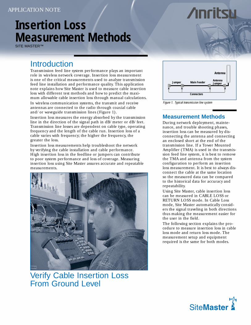
IntroductionTransmission feed line system performance plays an importantrole in wireless network coverage. Insertion loss measurementis one of the critical measurements used to analyze transmissionfeed line installation and performance quality. This applicationnote explains how Site Master is used to measure cable insertionloss with different test methods and how to predict the maxi-mum allowable cable insertion loss through manual calculations.In wireless communication systems, the transmit and receiveantennas are connected to the radio through coaxial cableand/or waveguide transmission lines (Figure 1).Insertion loss measures the energy absorbed by the transmissionline in the direction of the signal path in dB/meter or dB/feet.Transmission line losses are dependent on cable type, operatingfrequency and the length of the cable run. Insertion loss of acable varies with frequency; the higher the frequency, thegreater the loss.Insertion loss measurements help troubleshoot the networkby verifying the cable installation and cable performance.High insertion loss in the feedline or jumpers can contributeto poor system performance and loss of coverage. Measuringinsertion loss using Site Master assures accurate and repeatablemeasurements.
SITE MASTER™
Verify Cable Insertion LossFrom Ground Level
Figure 1. Typical transmission line system
Jumper
Connectors
Main FeederAntennaJumper
Antenna
2
MeasuringInsertion LossUsing CABLELOSS MODE
Application Note
Required Equipment
• Site Master Model S11xx,S33xx, or S251x
• Precision Open/Short,Anritsu 22N50 orPrecisionOpen/Short/Load, AnritsuOSLN50LF
• Precision Load, AnritsuSM/PL
• Test Port Extension Cable,Anritsu 15NNF50-1.5C
• Optional 510-90 Adapter,DC to 7.5 GHz, 50 Ω,7/16(f)-N(m)
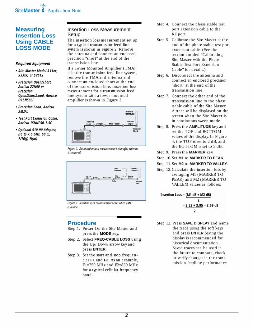
Figure 3. Insertion loss measurement setup when TMAis in line.
Step 4. Connect the phase stable testport extension cable to theRF port.
Step 5. Calibrate the Site Master at theend of the phase stable test portextension cable. (See thesection entitled “CalibratingSite Master with the PhaseStable Test Port ExtensionCable” for details.)
Step 6. Disconnect the antenna andconnect an enclosed precision"short" at the end of thetransmission line.
Step 7. Connect the other end of thetransmission line to the phasestable cable of the Site Master.A trace will be displayed on thescreen when the Site Master isin continuous sweep mode.
Step 8. Press the AMPLITUDE key andset the TOP and BOTTOMvalues of the display. In Figure4, the TOP is set to 2 dB, andthe BOTTOM is set to 5 dB.
Step 9. Press the MARKER key.Step 10.Set M1 to MARKER TO PEAK.Step 11.Set M2 to MARKER TO VALLEY.Step 12.Calculate the insertion loss by
averaging M1 (MARKER TOPEAK) and M2 (MARKER TOVALLEY) values as follows:
Step 13. Press SAVE DISPLAY and namethe trace using the soft keysand press ENTER.Saving thedisplay is recommended forhistorical documentation.Saved traces can be used inthe future to compare, checkor verify changes in the trans-mission feedline performance.
Insertion Loss = (M1 dB + M2 dB)2
= 3.23 + 3.95 = 3.59 dB2
ProcedureStep 1. Power On the Site Master and
press the MODE key.Step 2. Select FREQ-CABLE LOSS using
the Up/Down arrow key andpress ENTER.
Step 3. Set the start and stop frequen-cies F1 and F2. As an example,F1=750 MHz and F2=850 MHzfor a typical cellular frequencyband.
Insertion Loss MeasurementSetupThe insertion loss measurement set upfor a typical transmission feed linesystem is shown in Figure 2. Removethe antenna and connect an enclosedprecision “short” at the end of thetransmission line.If a Tower Mounted Amplifier (TMA)is in the transmission feed line system,remove the TMA and antenna andconnect an enclosed short at the endof the transmission line. Insertion lossmeasurement for a transmission feedline system with a tower mountedamplifier is shown in Figure 3.
Figure 2. An insertion loss measurement setup after antennais removed.
Site Master S251C
MODE FREQ/DIST AMPLITUDE SWEEP
1
5 6
ENTER
8
MARKER
7
LIMIT
3
STARTCAL
4
AUTOSCALE
SAVESETUP
RECALLSETUP
9
SAVEDISPLAY
ESCAPE
CLEAR
0
RECALLDISPLAY
SYSPRINT
.ONOFF
RUNHOLD
+/-
2
Test Port Cable Jumper Main Feeder
AntennaJumper
PrecisionShort
AntennaRemoved
Site Master S251C
MODE FREQ/DIST AMPLITUDE SWEEP
1
5 6
ENTER
8
MARKER
7
LIMIT
3
STARTCAL
4
AUTOSCALE
SAVESETUP
RECALLSETUP
9
SAVEDISPLAY
ESCAPE
CLEAR
0
RECALLDISPLAY
SYSPRINT
.ONOFF
RUNHOLD
+/-
2
Test Port Cable Jumper Main Feeder
TMA Jumper
AntennaJumper
PrecisionShort
AntennaRemoved
TMARemoved
Tx/Rx
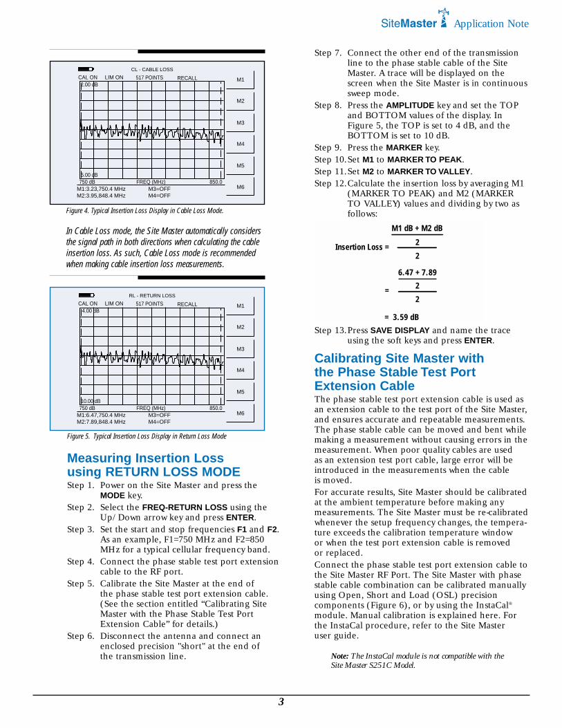
In Cable Loss mode, the Site Master automatically considersthe signal path in both directions when calculating the cableinsertion loss. As such, Cable Loss mode is recommendedwhen making cable insertion loss measurements.
3
Step 7. Connect the other end of the transmissionline to the phase stable cable of the SiteMaster. A trace will be displayed on thescreen when the Site Master is in continuoussweep mode.
Step 8. Press the AMPLITUDE key and set the TOPand BOTTOM values of the display. InFigure 5, the TOP is set to 4 dB, and theBOTTOM is set to 10 dB.
Step 9. Press the MARKER key.Step 10.Set M1 to MARKER TO PEAK.Step 11.Set M2 to MARKER TO VALLEY.Step 12.Calculate the insertion loss by averaging M1
(MARKER TO PEAK) and M2 (MARKERTO VALLEY) values and dividing by two asfollows:
Step 13.Press SAVE DISPLAY and name the traceusing the soft keys and press ENTER.
Calibrating Site Master withthe Phase Stable Test PortExtension CableThe phase stable test port extension cable is used asan extension cable to the test port of the Site Master,and ensures accurate and repeatable measurements.The phase stable cable can be moved and bent whilemaking a measurement without causing errors in themeasurement. When poor quality cables are usedas an extension test port cable, large error will beintroduced in the measurements when the cableis moved.For accurate results, Site Master should be calibratedat the ambient temperature before making anymeasurements. The Site Master must be re-calibratedwhenever the setup frequency changes, the tempera-ture exceeds the calibration temperature windowor when the test port extension cable is removedor replaced.Connect the phase stable test port extension cable tothe Site Master RF Port. The Site Master with phasestable cable combination can be calibrated manuallyusing Open, Short and Load (OSL) precisioncomponents (Figure 6), or by using the InstaCal®
module. Manual calibration is explained here. Forthe InstaCal procedure, refer to the Site Masteruser guide.
Note: The InstaCal module is not compatible with theSite Master S251C Model.
Insertion Loss = 2
2
= 3.59 dB
M1 dB + M2 dB
= 2
2
6.47 + 7.89
Figure 4. Typical Insertion Loss Display in Cable Loss Mode.
CL - CABLE LOSS
CAL ON LIM ON 517 POINTS RECALL M1
M2
M3
M4
M5
M6
2.00 dB
5.00 dB
M1:3.23,750.4 MHzM2:3.95,848.4 MHz
M3=OFFM4=OFF
750 dB FREQ (MHz) 850.0
RL - RETURN LOSS
CAL ON LIM ON 517 POINTS RECALL M1
M2
M3
M4
M5
M6
4.00 dB
10.00 dB
M1:6.47,750.4 MHzM2:7.89,848.4 MHz
M3=OFFM4=OFF
750 dB FREQ (MHz) 850.0
Figure 5. Typical Insertion Loss Display in Return Loss Mode
Measuring Insertion Lossusing RETURN LOSS MODEStep 1. Power on the Site Master and press the
MODE key.Step 2. Select the FREQ-RETURN LOSS using the
Up/Down arrow key and press ENTER.Step 3. Set the start and stop frequencies F1 and F2.
As an example, F1=750 MHz and F2=850MHz for a typical cellular frequency band.
Step 4. Connect the phase stable test port extensioncable to the RF port.
Step 5. Calibrate the Site Master at the end ofthe phase stable test port extension cable.(See the section entitled “Calibrating SiteMaster with the Phase Stable Test PortExtension Cable” for details.)
Step 6. Disconnect the antenna and connect anenclosed precision "short" at the end ofthe transmission line.
Application Note

Figure. Calibrating atthe end of the PhaseStable Test PortExtension Cable.
Discover What’s Possible®
SALES CENTERS:United States (800) ANRITSU Europe 44 (0) 1582-433433 Microwave Measurements DivisionCanada (800) ANRITSU Japan 81 (03) 3446-1111 490 Jarvis Drive, Morgan Hill, CA 95037-2809South America 55 (21) 286-9141 Asia-Pacific 65-2822400 http://www.us.anritsu.com
Application Note
For example:
Site Master S331C
MODE FREQ/DIST AMPLITUDE SWEEP
1
5 6
ENTER
8
MARKER
7
LIMIT
3
STARTCAL
4
AUTOSCALE
SAVESETUP
RECALLSETUP
9
SAVEDISPLAY
ESCAPE
CLEAR
0
RECALLDISPLAY
SYSPRINT
.ONOFF
RUNHOLD
+/-
2
RF Out/ReflectionTest Port
Site Master S11xx/S33xx/S251x
Test Port Cable (Optional)
Open
Short
Load
Calibration
Manual Calibration ProcedureStep 1. Power on the Site Master.Step 2. Select the appropriate frequency range.Step 3. Connect the phase stable test port extension cable to
the RF port.Step 4. Press the START CAL key. The message "Connect Open to
RF OUT port or connect InstaCal module and press ENTER"will appear in the display.
Step 5. Connect the OPEN precision calibration componentto the end of the test port extension cable. Press the ENTERKey.
Step 6. The message "Measuring OPEN" will appear, and after themeasurement "Connect SHORT to RF OUT" will appear.
Step 7. Remove the “open” and connect the “short” precision cali-bration component to the test port extension cable.Press the ENTER key.
Step 8. The message "Measuring SHORT" will appear, and after themeasurement "Connect TERMINATION to RF OUT" willappear.
Step 9. Remove the “short” and connect the “precision termination”at the end of the test port extension cable. Press the ENTERkey.
Step 10.The message "Measuring TERMINATION" will appear. Afterthe measurement, the “CAL OFF” message will change to"CAL ON" on the upper left-hand corner of the display.
Step 11.Remove the precision termination from the text portextension cable.
Calculating Transmission Line Insertion LossCables have different insertion losses at different frequencies.For example LDF4-40A attenuation at 1 GHz is 0.022 dB/ft(0.073 dB/m) and at 2 GHz it is 0.0325 dB/ft (0.107 dB/m).As the frequency increases or the length of the cable run increases,the amount of cable insertion loss increases.To verify cable insertion loss measurements are reasonable, theexpected insertion loss can be calculated manually using thefollowing procedure:• Calculate the estimated worst loss of each component in the
transmission line system.• Add all the component’s estimated worst losses together to
calculate total insertion loss in the transmission line system.
Insertion loss of the = Bottom Jumper Loss transmission system + Main Cable Loss
+ Top Jumper Loss+ Connector Losses
= 0.408 + 2.3 +0.204 +1.12= 4.03 dB
Compare the measured insertion loss tothe calculated insertion loss to verifytransmission line performance. Themeasured cable insertion loss should belower than the calculated cable inser-tion loss.
SummaryThe preferred method to measureCable Insertion Loss using Site Masteris Cable Loss mode. Cable loss modeautomatically considers the signaltraveling in both directions and thusmakes it easier to measure the cableinsertion loss in the field. MeasuredInsertion Loss should always be com-pared to the calculated loss to verifyaccuracy thus assuring transmission lineperformance. The calculated insertionloss is usually a “worst case scenario”.Cable insertion loss may be difficult tomeasure on excessivly long or highlylossy cables. When the cable insertionloss is greater than 20 dB, it will be hardto measure.
All trademarks used are the property of theirrespective owners.
Cable Type
CableAttenuation (dB/ft)
CableLength
InsertionLoss (dB)
BottomJumper
LDF4-50A 0.0204 X 20 = 0.408
MainCable
LDF5-50A 0.0115 X 200 = 2.30
TopJumper
LDF4-50A 0.0204 X 10 = 0.204
Number ofConnector Pairs
Loss per Pairin dB
Total ConnectorLoss (dB)
4 X 0.28 = 1.12
Note: For Cable Loss-One Portmeasurements, Site Master S251Crequires only one port calibration.Note: If the phase stable cable isremoved from the test port, thecalibration is not valid.
11410-00276 Rev. A, ©Anritsu March 2003, Data subject to change without notice