insert document title aviation short investigations bulletin · location | date atsb transport ......
TRANSCRIPT
Insert document title
Location | Date
ATSB Transport Safety Report[Insert Mode] Occurrence InvestigationXX-YYYY-####Final
Investigation
Aviation Short Investigations Bulletin
InvestigationATSB Transport Safety ReportAviation Short InvestigationsAB-2017-036Final – 27 April 2017
Issue 59
Released in accordance with section 25 of the Transport Safety Investigation Act 2003
Publishing information
Published by: Australian Transport Safety Bureau Postal address: PO Box 967, Civic Square ACT 2608 Office: 62 Northbourne Avenue Canberra, Australian Capital Territory 2601 Telephone: 1800 020 616, from overseas +61 2 6257 4150 (24 hours) Accident and incident notification: 1800 011 034 (24 hours) Facsimile: 02 6247 3117, from overseas +61 2 6247 3117 Email: [email protected] Internet: www.atsb.gov.au
© Commonwealth of Australia 2017
Ownership of intellectual property rights in this publication Unless otherwise noted, copyright (and any other intellectual property rights, if any) in this publication is owned by the Commonwealth of Australia.
Creative Commons licence With the exception of the Coat of Arms, ATSB logo, and photos and graphics in which a third party holds copyright, this publication is licensed under a Creative Commons Attribution 3.0 Australia licence.
Creative Commons Attribution 3.0 Australia Licence is a standard form license agreement that allows you to copy, distribute, transmit and adapt this publication provided that you attribute the work.
The ATSB’s preference is that you attribute this publication (and any material sourced from it) using the following wording: Source: Australian Transport Safety Bureau
Copyright in material obtained from other agencies, private individuals or organisations, belongs to those agencies, individuals or organisations. Where you want to use their material you will need to contact them directly.
Contents Jet aircraft Engine failure involving Airbus A320, VH-VFY ...................................................................................2 Tail skid contact involving Boeing 777-312, 9V-SYG .........................................................................6 Loading related event involving Airbus A320, VH-VGI .................................................................... 11 Aircraft loading event involving Boeing 737, ZK-TLK ...................................................................... 15
Turboprop aircraft Engine shut down involving British Aerospace Jetstream 32, VH-OTQ ......................................... 20 Collision with terrain involving Air Tractor AT-401, VH-DDW .......................................................... 24
Piston aircraft Landing accident involving Van's RV-6A, VH-TJM .......................................................................... 29
Helicopters Forced landing involving Robinson R44, VH-SJK............................................................................ 34
Unmanned aircraft Collision with terrain involving Lockheed Martin Stalker XE VTOL UAS ........................................ 40
Separation issues Call sign confusion involving Airbus A330, VH-EBA, and Boeing 737, VH-VXF ............................ 45

› 1 ‹
Jet aircraft
› 2 ‹
ATSB – AO-2016-123
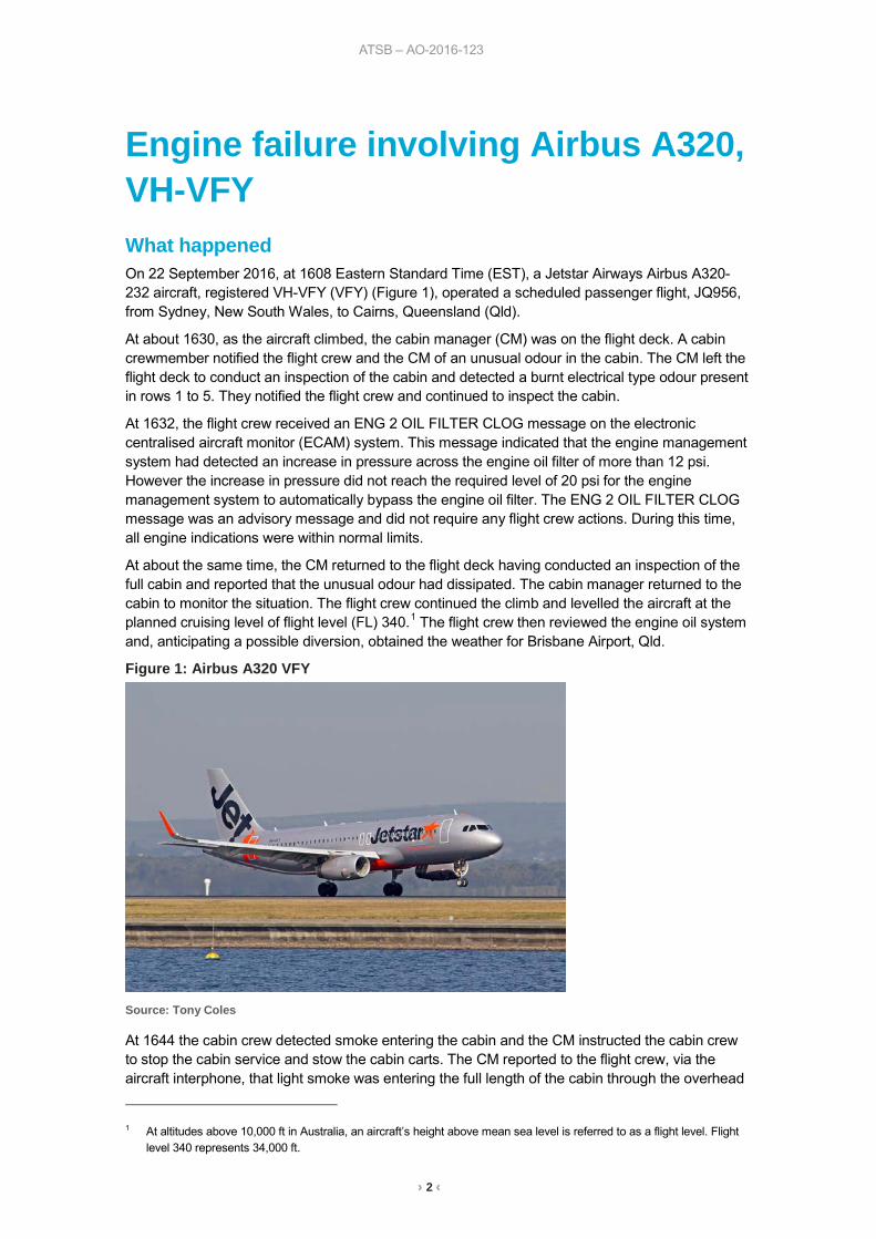
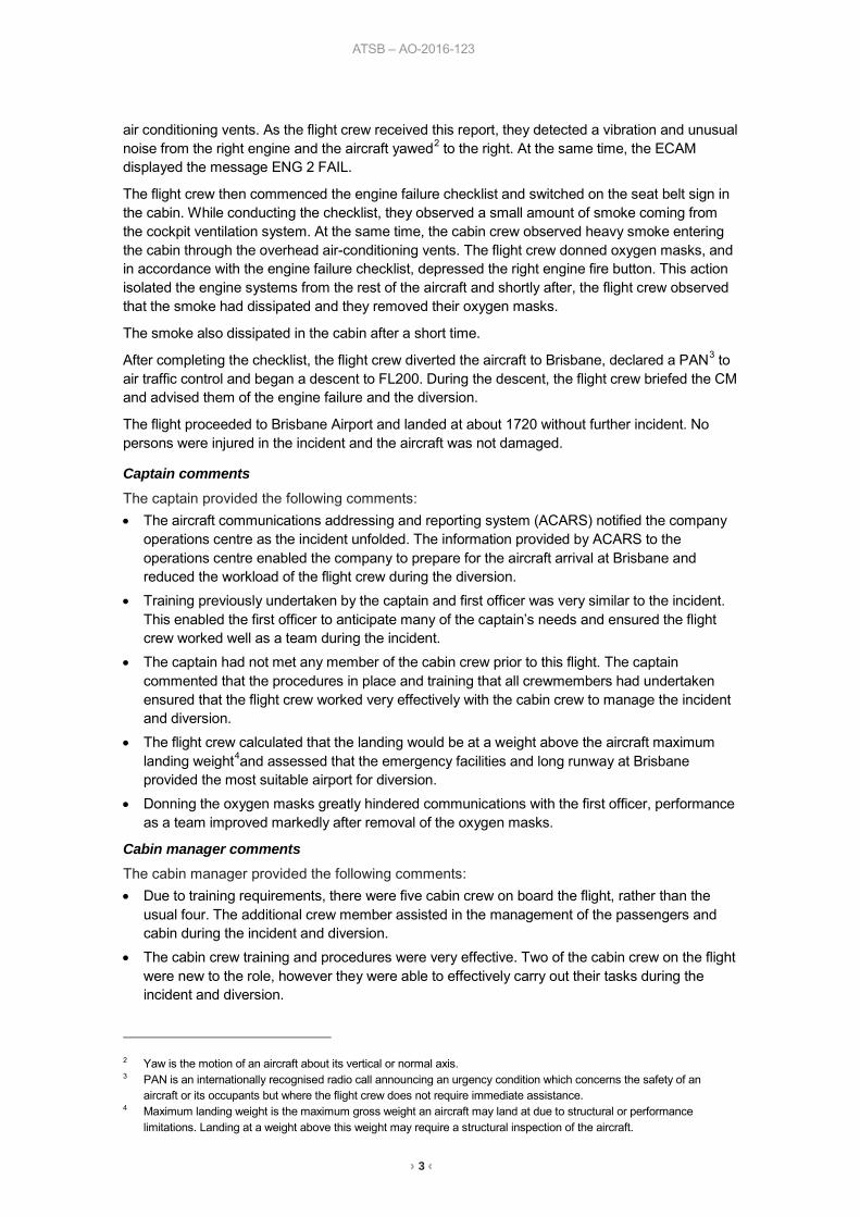
Engine failure involving Airbus A320, VH-VFY What happened On 22 September 2016, at 1608 Eastern Standard Time (EST), a Jetstar Airways Airbus A320-232 aircraft, registered VH-VFY (VFY) (Figure 1), operated a scheduled passenger flight, JQ956, from Sydney, New South Wales, to Cairns, Queensland (Qld).
At about 1630, as the aircraft climbed, the cabin manager (CM) was on the flight deck. A cabin crewmember notified the flight crew and the CM of an unusual odour in the cabin. The CM left the flight deck to conduct an inspection of the cabin and detected a burnt electrical type odour present in rows 1 to 5. They notified the flight crew and continued to inspect the cabin.
At 1632, the flight crew received an ENG 2 OIL FILTER CLOG message on the electronic centralised aircraft monitor (ECAM) system. This message indicated that the engine management system had detected an increase in pressure across the engine oil filter of more than 12 psi. However the increase in pressure did not reach the required level of 20 psi for the engine management system to automatically bypass the engine oil filter. The ENG 2 OIL FILTER CLOG message was an advisory message and did not require any flight crew actions. During this time, all engine indications were within normal limits.
At about the same time, the CM returned to the flight deck having conducted an inspection of the full cabin and reported that the unusual odour had dissipated. The cabin manager returned to the cabin to monitor the situation. The flight crew continued the climb and levelled the aircraft at the planned cruising level of flight level (FL) 340.1 The flight crew then reviewed the engine oil system and, anticipating a possible diversion, obtained the weather for Brisbane Airport, Qld.
Figure 1: Airbus A320 VFY
Source: Tony Coles
At 1644 the cabin crew detected smoke entering the cabin and the CM instructed the cabin crew to stop the cabin service and stow the cabin carts. The CM reported to the flight crew, via the aircraft interphone, that light smoke was entering the full length of the cabin through the overhead
1 At altitudes above 10,000 ft in Australia, an aircraft’s height above mean sea level is referred to as a flight level. Flight
level 340 represents 34,000 ft.
› 3 ‹
ATSB – AO-2016-123
air conditioning vents. As the flight crew received this report, they detected a vibration and unusual noise from the right engine and the aircraft yawed2 to the right. At the same time, the ECAM displayed the message ENG 2 FAIL.
The flight crew then commenced the engine failure checklist and switched on the seat belt sign in the cabin. While conducting the checklist, they observed a small amount of smoke coming from the cockpit ventilation system. At the same time, the cabin crew observed heavy smoke entering the cabin through the overhead air-conditioning vents. The flight crew donned oxygen masks, and in accordance with the engine failure checklist, depressed the right engine fire button. This action isolated the engine systems from the rest of the aircraft and shortly after, the flight crew observed that the smoke had dissipated and they removed their oxygen masks.
The smoke also dissipated in the cabin after a short time.
After completing the checklist, the flight crew diverted the aircraft to Brisbane, declared a PAN3 to air traffic control and began a descent to FL200. During the descent, the flight crew briefed the CM and advised them of the engine failure and the diversion.
The flight proceeded to Brisbane Airport and landed at about 1720 without further incident. No persons were injured in the incident and the aircraft was not damaged.
Captain comments The captain provided the following comments: • The aircraft communications addressing and reporting system (ACARS) notified the company
operations centre as the incident unfolded. The information provided by ACARS to the operations centre enabled the company to prepare for the aircraft arrival at Brisbane and reduced the workload of the flight crew during the diversion.
• Training previously undertaken by the captain and first officer was very similar to the incident. This enabled the first officer to anticipate many of the captain’s needs and ensured the flight crew worked well as a team during the incident.
• The captain had not met any member of the cabin crew prior to this flight. The captain commented that the procedures in place and training that all crewmembers had undertaken ensured that the flight crew worked very effectively with the cabin crew to manage the incident and diversion.
• The flight crew calculated that the landing would be at a weight above the aircraft maximum landing weight4and assessed that the emergency facilities and long runway at Brisbane provided the most suitable airport for diversion.
• Donning the oxygen masks greatly hindered communications with the first officer, performance as a team improved markedly after removal of the oxygen masks.
Cabin manager comments The cabin manager provided the following comments: • Due to training requirements, there were five cabin crew on board the flight, rather than the
usual four. The additional crew member assisted in the management of the passengers and cabin during the incident and diversion.
• The cabin crew training and procedures were very effective. Two of the cabin crew on the flight were new to the role, however they were able to effectively carry out their tasks during the incident and diversion.
2 Yaw is the motion of an aircraft about its vertical or normal axis. 3 PAN is an internationally recognised radio call announcing an urgency condition which concerns the safety of an
aircraft or its occupants but where the flight crew does not require immediate assistance. 4 Maximum landing weight is the maximum gross weight an aircraft may land at due to structural or performance
limitations. Landing at a weight above this weight may require a structural inspection of the aircraft.
› 4 ‹
ATSB – AO-2016-123
Engineering examination After the incident, the engine manufacturer, International Aero Engines (IAE), conducted an engineering examination of the engine and detected that the number 3 bearing had failed. A detailed examination of the bearing was conducted. IAE reported that due to secondary damage, the engineering examination could not determine the cause of the number three bearing failure. IAE reported that the ball material was found to be compliant with manufacturing quality requirements.
Airworthiness directives In 2007, the Civil Aviation Safety Authority released airworthiness directive (AD) AD/V2500/3 relating to failures of the number 3 bearing within IAE V2500 series engines within a specified range of serial numbers. This airworthiness directive did not apply to the IAE V2527-A5 engine fitted to VFY, as the serial number (V17515) for the engine was outside the specified range, however the AD contained the following information:
The issuing of this AD is to prevent failure of the number three bearing, which could result in an in-flight shutdown and smoke in the cockpit and cabin. The smoke is a result of oil escaping from the bearing compartment due to a fracture of the number three bearing race.
The United States Federal Aviation Administration released AD 2016-25-11, which has an effective date of 20 January 2017. This AD also required inspections and corrective actions for damage to the number 3 bearing. The FAA released this AD after the premature failure of number 3 bearings resulted in nine in-flight engine shutdowns. The AD does not apply to the engine fitted on VFY, as the serial number was once again outside of the specified range.
Applicability of airworthiness directives The ADs were introduced after failures of the number three bearing led to the discovery of microstructural defects in some bearing components, introduced during the manufacturing process. Following this discovery, the engine manufacturer reviewed manufacturing records to determine the extent of engines with affected bearings. The engines with the highest level of number 3 bearing material defects, and therefore the highest risk of failure, were included in the original AD. Engines determined to have a lesser level of defects required additional inspections and/or were subject to reduced service life. The second AD was introduced to increase the number of engines affected. IAE advised that V2500 series engine-powered A320 aircraft currently achieve an in-flight shut down rate of 0.00136 per 1,000 flight hours. This exceeds IAE’s target in flight shut down rate, of 0.02 per 1,000 flight hours.5 IAE investigates the cause of each in-flight shut down and takes corrective actions with the goal of maintaining the target in-flight shut down rate. IAE will continue to monitor the performance of the bearings and will adjust the fleet management plan if required.
The engine manufacturer and the United States Federal Aviation Administration advised that no further actions were planned beyond the current ADs.
The Civil Aviation Safety Authority (CASA) commented that they are monitoring the situation and awaiting reports from the aircraft operator and engine manufacturer.
Safety analysis The initial odour detected by the cabin crewmembers during the aircraft’s climb, along with the ENG 2 OIL FILTER CLOG ECAM message, likely resulted from the early stages of the number 3
5 0.02 per 1,000 flight hours is the rate required for an engine and airframe combination to achieve the acceptable in-
flight shut rate for 180 min extended operations.
› 5 ‹
ATSB – AO-2016-123
bearing failure. The later instance of smoke in the cabin and flight deck occurred as the bearing failed. The failure of the number 3 bearing resulted in a complete power loss from the right engine.
Findings These findings should not be read as apportioning blame or liability to any particular organisation or individual.
• The right engine number 3 bearing failed, resulting in engine power loss and led to smoke entering the flight deck and cabin.
Safety message This incident highlights the importance of effective crew management techniques, training and robust emergency procedures. The captain had not met any of the other flight and cabin crewmembers prior to the flight. In addition to this, some cabin crewmembers were new to the role. Despite this, the emergency procedures and training undertaken by the crewmembers ensured that they were able to fulfil their roles and work effectively as a team to manage a difficult situation safely and efficiently.
General details Occurrence details
Date and time: 22 September 2016 – 1644 EST
Occurrence category: Incident
Primary occurrence type: Engine failure or malfunction
Location: 40 km NNW of Narrabri Airport, New South Wales
Latitude: 29° 58.150’ S Longitude: 149° 43.580’ E
Aircraft details Manufacturer and model: Airbus A320
Registration: VH-VFY
Operator: Jetstar Airways
Serial number: 6362
Type of operation: Air transport high capacity - Passenger
Persons on board: Crew – 7 Passengers – 172
Injuries: Crew – 0 Passengers – 0
Aircraft damage: Nil
› 6 ‹
ATSB – AO-2016-131
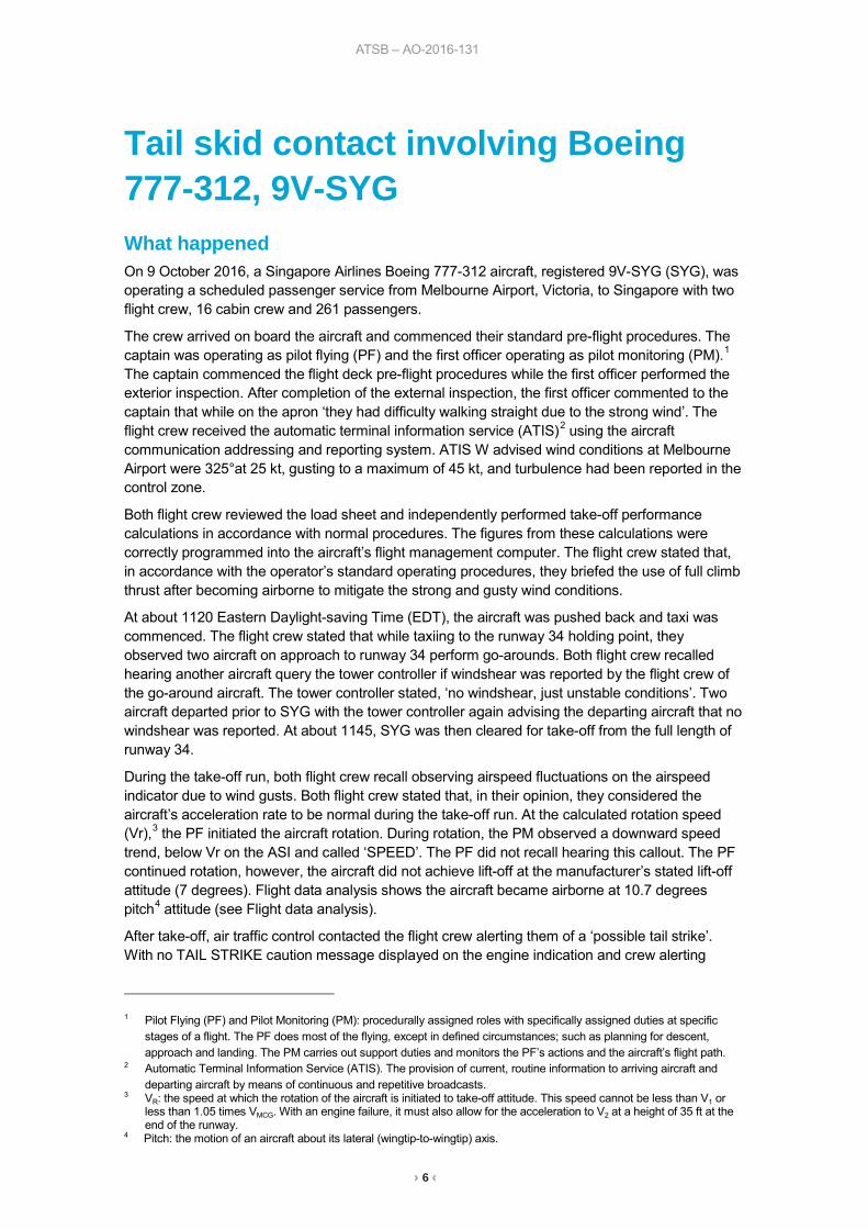
Tail skid contact involving Boeing 777-312, 9V-SYG What happened On 9 October 2016, a Singapore Airlines Boeing 777-312 aircraft, registered 9V-SYG (SYG), was operating a scheduled passenger service from Melbourne Airport, Victoria, to Singapore with two flight crew, 16 cabin crew and 261 passengers.
The crew arrived on board the aircraft and commenced their standard pre-flight procedures. The captain was operating as pilot flying (PF) and the first officer operating as pilot monitoring (PM).1 The captain commenced the flight deck pre-flight procedures while the first officer performed the exterior inspection. After completion of the external inspection, the first officer commented to the captain that while on the apron ‘they had difficulty walking straight due to the strong wind’. The flight crew received the automatic terminal information service (ATIS)2 using the aircraft communication addressing and reporting system. ATIS W advised wind conditions at Melbourne Airport were 325°at 25 kt, gusting to a maximum of 45 kt, and turbulence had been reported in the control zone.
Both flight crew reviewed the load sheet and independently performed take-off performance calculations in accordance with normal procedures. The figures from these calculations were correctly programmed into the aircraft’s flight management computer. The flight crew stated that, in accordance with the operator’s standard operating procedures, they briefed the use of full climb thrust after becoming airborne to mitigate the strong and gusty wind conditions.
At about 1120 Eastern Daylight-saving Time (EDT), the aircraft was pushed back and taxi was commenced. The flight crew stated that while taxiing to the runway 34 holding point, they observed two aircraft on approach to runway 34 perform go-arounds. Both flight crew recalled hearing another aircraft query the tower controller if windshear was reported by the flight crew of the go-around aircraft. The tower controller stated, ‘no windshear, just unstable conditions’. Two aircraft departed prior to SYG with the tower controller again advising the departing aircraft that no windshear was reported. At about 1145, SYG was then cleared for take-off from the full length of runway 34.
During the take-off run, both flight crew recall observing airspeed fluctuations on the airspeed indicator due to wind gusts. Both flight crew stated that, in their opinion, they considered the aircraft’s acceleration rate to be normal during the take-off run. At the calculated rotation speed (Vr),3 the PF initiated the aircraft rotation. During rotation, the PM observed a downward speed trend, below Vr on the ASI and called ‘SPEED’. The PF did not recall hearing this callout. The PF continued rotation, however, the aircraft did not achieve lift-off at the manufacturer’s stated lift-off attitude (7 degrees). Flight data analysis shows the aircraft became airborne at 10.7 degrees pitch4 attitude (see Flight data analysis).
After take-off, air traffic control contacted the flight crew alerting them of a ‘possible tail strike’. With no TAIL STRIKE caution message displayed on the engine indication and crew alerting
1 Pilot Flying (PF) and Pilot Monitoring (PM): procedurally assigned roles with specifically assigned duties at specific
stages of a flight. The PF does most of the flying, except in defined circumstances; such as planning for descent, approach and landing. The PM carries out support duties and monitors the PF’s actions and the aircraft’s flight path.
2 Automatic Terminal Information Service (ATIS). The provision of current, routine information to arriving aircraft and departing aircraft by means of continuous and repetitive broadcasts.
3 VR: the speed at which the rotation of the aircraft is initiated to take-off attitude. This speed cannot be less than V1 or less than 1.05 times VMCG. With an engine failure, it must also allow for the acceleration to V2 at a height of 35 ft at the end of the runway.
4 Pitch: the motion of an aircraft about its lateral (wingtip-to-wingtip) axis.
› 7 ‹
ATSB – AO-2016-131
system5 the flight crew carried out the unannunciated tail strike non-normal checklist and determined the aircraft structural integrity was intact. The flight crew then referred to the operator’s supplementary procedures for further guidance.
An inspection of the runway identified contact marks, consistent with a tail skid contact. No metallic debris was observed on the runway. Air traffic control advised the flight crew that ‘only superficial concrete debris was found’ during the runway inspection. The captain communicated with the in-flight supervisor who reported back to the captain that cabin crew stationed at the rear of the aircraft heard a ‘loud bang’ during take-off.
The flight crew discussed all the available information and considered their options. With the aircraft pressurisation system indicating no abnormalities the captain made the decision to continue to the destination. This decision was supported by manufacturer’s recommended action to continue to operate normally in the case of an unannunciated tail strike in the B777-300 aircraft.
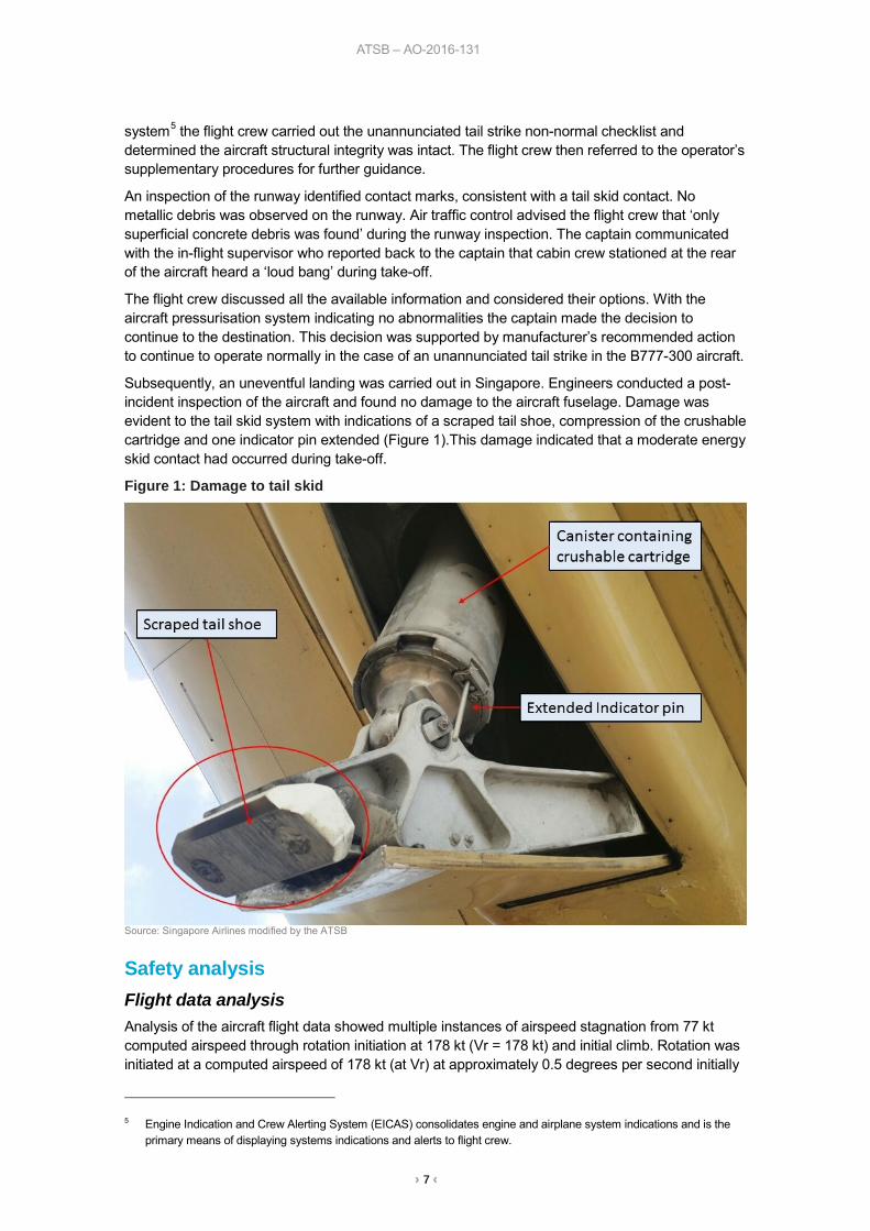
Subsequently, an uneventful landing was carried out in Singapore. Engineers conducted a post-incident inspection of the aircraft and found no damage to the aircraft fuselage. Damage was evident to the tail skid system with indications of a scraped tail shoe, compression of the crushable cartridge and one indicator pin extended (Figure 1).This damage indicated that a moderate energy skid contact had occurred during take-off.
Figure 1: Damage to tail skid
Source: Singapore Airlines modified by the ATSB
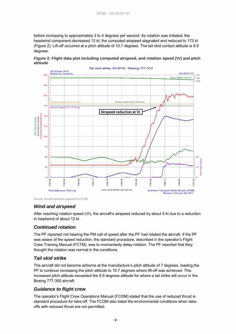
Safety analysis Flight data analysis
Analysis of the aircraft flight data showed multiple instances of airspeed stagnation from 77 kt computed airspeed through rotation initiation at 178 kt (Vr = 178 kt) and initial climb. Rotation was initiated at a computed airspeed of 178 kt (at Vr) at approximately 0.5 degrees per second initially
5 Engine Indication and Crew Alerting System (EICAS) consolidates engine and airplane system indications and is the
primary means of displaying systems indications and alerts to flight crew.
› 8 ‹
ATSB – AO-2016-131
before increasing to approximately 3 to 4 degrees per second. As rotation was initiated, the headwind component decreased 12 kt, the computed airspeed stagnated and reduced to 173 kt (Figure 2). Lift-off occurred at a pitch attitude of 10.7 degrees. The tail skid contact attitude is 8.9 degrees.
Figure 2: Flight data plot including computed airspeed, and rotation speed (Vr) and pitch attitude
Source: Aircraft operator analysed by ATSB
Wind and airspeed After reaching rotation speed (Vr), the aircraft’s airspeed reduced by about 5 kt due to a reduction in headwind of about 12 kt.
Continued rotation The PF reported not hearing the PM call of speed after the PF had rotated the aircraft. If the PF was aware of the speed reduction, the standard procedure, described in the operator’s Flight Crew Training Manual (FCTM), was to momentarily delay rotation. The PF reported that they thought the rotation was normal in the conditions.
Tail skid strike The aircraft did not become airborne at the manufacture’s pitch attitude of 7 degrees, leading the PF to continue increasing the pitch attitude to 10.7 degrees where lift-off was achieved. This increased pitch attitude exceeded the 8.9 degrees attitude for where a tail strike will occur in the Boeing 777-300 aircraft.
Guidance to flight crew The operator’s Flight Crew Operations Manual (FCOM) stated that the use of reduced thrust is standard procedure for take-off. The FCOM also listed the environmental conditions when take-offs with reduced thrust are not permitted.
› 9 ‹
ATSB – AO-2016-131
The operator’s FCOM does not contain direct guidance regarding take-off thrust setting requirements in gusty wind and strong crosswind conditions. Guidance for considering the use of higher thrust settings and rotation speeds for take-offs under these environmental conditions is provided in the Flight Crew Training Manual (FCTM).
Findings These findings should not be read as apportioning blame or liability to any particular organisation or individual.
• The tail skid contact was a result of airspeed stagnation due to gusty atmospheric conditions which prolonged the time to lift-off, allowing the pitch attitude to exceed the tail skid contact attitude.
• The use of a higher take-off thrust setting would most likely have reduced the required runway length and minimised the aircraft exposure to gusty atmospheric conditions during rotation and lift-off.
Safety action Whether or not the ATSB identifies safety issues in the course of an investigation, relevant organisations may proactively initiate safety action in order to reduce their safety risk. The ATSB has been advised of the following safety action in response to this occurrence.
Flight Operations As a result of this occurrence, Singapore Airlines has advised the ATSB that they are taking the following safety actions:
Action taken by Singapore Airlines As a result of this incident, the aircraft operator issued circulars to all company flight crew directing operation towards Boeing’s recommendation of the use of higher thrust and rotation speed for take-off in gusty wind and strong crosswind conditions.
Safety message This incident serves as a reminder to Boeing pilots that guidance material contained in manuals outside the FCOM should be considered in all aircraft operations. The use of a higher thrust setting as recommended by the Boeing FCTM would have reduced the required runway length and minimised the airplane exposure to gusty conditions during rotation, lift-off and initial climb. Boeing also states that the use of a higher take-off rotation speed, if take-off performance permits, can increase the tail clearance margin during the rotation. While taking the above message into consideration, this incident provides an excellent example of flight crew managing a non-normal operation. Throughout the non-normal occurrence period, the flight crew communicated with each other, air traffic control and the cabin crew, which allowed all relevant information available to be gathered. The flight crew demonstrated effective crew resource management and decision making resulting in the flight being able to continue to destination without compromising safety.
› 10 ‹
ATSB – AO-2016-131
General details Occurrence details
Date and time: 9 October 2016 – 1145 EDT
Occurrence category: Incident
Primary occurrence type: Ground strike
Location: Melbourne Airport, Victoria
Latitude: 37° 40.12’ S Longitude: 144° 50.24’ E
Aircraft details Manufacturer and model: The Boeing Company 777-312
Registration: 9V-SYG
Serial number: 28528
Operator: Singapore Airlines
Type of operation: Air transport high capacity - Passenger
Persons on board: Crew – 18 Passengers – 261
Injuries: Crew – 0 Passengers – 0
Aircraft damage: Minor
› 11 ‹
ATSB – AO-2016-177
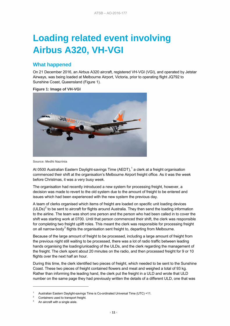
Loading related event involving Airbus A320, VH-VGI What happened On 21 December 2016, an Airbus A320 aircraft, registered VH-VGI (VGI), and operated by Jetstar Airways, was being loaded at Melbourne Airport, Victoria, prior to operating flight JQ792 to Sunshine Coast, Queensland (Figure 1).
Figure 1: Image of VH-VGI
Source: Medhi Nazrinia
At 0500 Australian Eastern Daylight-savings Time (AEDT),1 a clerk at a freight organisation commenced their shift at the organisation’s Melbourne Airport freight office. As it was the week before Christmas, it was a very busy week.
The organisation had recently introduced a new system for processing freight, however, a decision was made to revert to the old system due to the amount of freight to be entered and issues which had been experienced with the new system the previous day.
A team of clerks organised which items of freight are loaded on specific unit loading devices (ULDs)2 to be sent to aircraft for flights around Australia. They then send the loading information to the airline. The team was short one person and the person who had been called in to cover the shift was starting work at 0700. Until that person commenced their shift, the clerk was responsible for completing two freight uplift roles. This meant the clerk was responsible for processing freight on all narrow-body3 flights the organisation sent freight to, departing from Melbourne.
Because of the large amount of freight to be processed, including a large amount of freight from the previous night still waiting to be processed, there was a lot of radio traffic between leading hands organising the loading/unloading of the ULDs, and the clerk regarding the management of the freight. The clerk spent about 20 minutes on the radio, and then processed freight for 9 or 10 flights over the next half an hour.
During this time, the clerk identified two pieces of freight, which needed to be sent to the Sunshine Coast. These two pieces of freight contained flowers and meat and weighed a total of 93 kg. Rather than informing the leading hand, the clerk put the freight in a ULD and wrote that ULD number on the same page they had previously written the details of a different ULD, one that was
1 Australian Eastern Daylight-savings Time is Co-ordinated Universal Time (UTC) +11. 2 Containers used to transport freight. 3 An aircraft with a single aisle.
› 12 ‹
ATSB – AO-2016-177
to be sent to Adelaide. The clerk then went to the office and the ULD was processed as going to the Sunshine Coast; however, when the clerk returned to the ULD with the freight, they inadvertently put the Sunshine Coast freight card on the ULD destined for Adelaide. This ULD contained medical goods with a gross weight of 245 kg. This ULD was subsequently loaded on the flight to the Sunshine Coast.
The clerk realised an error was made when the ULD, which was intended to go to Adelaide, could not be located. The clerk, who commenced work at 0700, noticed the same number ULD on the Sunshine Coast flight paperwork and they then found the ULD that was supposed to go to the Sunshine Coast. That ULD was put on the next flight to the Sunshine Coast.
Once the error was detected, the clerk rang the Sunshine Coast freight office. They were informed the incorrect container had been sent and provided them with details of the freight so the ULD could be sent back to Melbourne, then to Adelaide.
The aircraft remained within all weight and balance limits during the flight.
Freight processing systems The organisation was transitioning between an old and new processing system. In the old processing system, all information (such as weight and container number) was entered into an office computer. It was also the clerks’ responsibility for planning which flight the freight will go on and they rely on information from the leading hands for the freight details. The clerk would write the number of the container down, enter the number via the computer and then they would itemise the freight that had gone into the container. The cards itemising the freight would be printed out and attached to the container.
In the new system, information is entered on tablet computers. It is the customer’s responsibility to book their freight onto flights themselves. Staff are on the floor and are required to put the piece of freight in a container and enter the details on the tablet in succession. The system has built in checks, which would not allow the same number ULD to be used. This new system had been introduced about a week prior to the incident, but due to technical issues, they had reverted to using the old system.
Clerk’s comments The clerk provided the following comments:
• They felt very busy. Within the first hour, they would have processed freight for about 9 to 10 flights, which was double the usual workload.
• They had to process all flights to Adelaide, Brisbane, Canberra, Alice Springs, and Townsville, as well as all other narrow-body flights. Normally this role would be divided between two clerks.
• If there is a person unable to work their shift, they try to find a replacement. They had done so in this case, but the replacement could not start until 0700.
• Normally at Christmas time, they would have extra staff rostered, but that year they did not. • On the day, they felt under stress due to the busy time of year.
Previous occurrences A search of the ATSB’s occurrence database found occurrences relating to incorrect loading information being processed, particularly when staff were under high workload:
• On 16 May 2010, an Embraer ERJ 190 aircraft was operated on a positioning flight from Adelaide, South Australia to Brisbane, Queensland (ATSB investigation AO-2010-034). The pilot-in-command reported that the load and trim sheet for the aircraft was inaccurate due to items being counted twice. It was found that the error occurred when the airport movements coordinator inadvertently selected the incorrect aircraft configuration in the company’s computerised load and trim system during a high workload time.
› 13 ‹
ATSB – AO-2016-177
• On 8 September 2016, an Airbus A320 aircraft was being loaded at Sydney Airport, New South Wales to Brisbane, Queensland (ATSB investigation AO-2016-119). The leading hand received the deadload weight statement (DWS) and checked the containers. The third container number (1483) did not match the number listed on the DWS (4183), nor the container card (4183). The leading hand assumed that the freight handler had inadvertently transposed the numbers incorrectly and amended the card and DWS with 1483 and continued loading. When the aircraft was unloaded in Brisbane, it was found that the incorrect container (1483) was delivered and was nearly 650kg heavier than container 4183. The loading procedure if the DWS is incorrect, is that the container must not be loaded onto the aircraft. The leading hand noted that the short turnaround time and the flight was the last one of the day led to procedures being bypassed.
Safety analysis An incorrect ULD, weighing 245 kg was loaded onto VGI operating the Sunshine Coast flight, where the load sheet recorded a ULD of 93 kg. The error occurred when the clerk put the freight card for the Sunshine Coast flight on the Adelaide ULD, and the card for the Adelaide flight on the Sunshine Coast ULD. The Adelaide ULD was then sent to the Sunshine Coast. Because these ULDs had the same ULD number, it is likely the clerk misread the flight details and put the cards on the incorrect ULDs.
In the old processing system, the same ULD number can be entered twice into the system. In the new system, this would result in an error feedback. Without the error feedback, the clerk would not have known that the same container was entered twice. Furthermore, this data cross check is completed by the same person who entered it, making it difficult to detect any errors, particularly if they are experiencing a high workload.
The same error involving heavier weights could have a significant impact on the handling and performance of an aircraft.
Findings These findings should not be read as apportioning blame or liability to any particular organisation or individual:
• The incorrect ULD card was placed on the Adelaide ULD, leading it to be sent to the Sunshine Coast.
• There was no error feedback on the old system of entering information into an office computer meaning the clerk would not have realised they had entered the same container number twice in the system.
• Due to the absence of a staff member and the time of the year, the clerk was experiencing a high workload as they were required to take the responsibility for organising freight for all narrow body flights, rather than dividing them between two people.
Safety action Whether or not the ATSB identifies safety issues in the course of an investigation, relevant organisations may proactively initiate safety action in order to reduce their safety risk. The ATSB has been advised of the following proactive safety action in response to this occurrence.
Freight organisation As a result of this occurrence, the aircraft operator has advised the ATSB that they are taking the following safety actions:
› 14 ‹
ATSB – AO-2016-177
• The operator issued a revised loading instruction to prevent a recurrence of this type of event. The instruction stated after weighing the ULD or barrow4, immediately record the weight on the appropriate ULD or barrow card and immediately insert in the ULD/Barrow pocket. Then close load in the Cargo system and move the ULD/Barrow to the designated staging area away from build-up areas.
Safety message This investigation highlights the effect of high workload on data input errors, as well as the importance of system feedback to indicate that the correct data has been entered. One of the ATSB’s SafetyWatch priorities is data input errors. These errors, such as using the incorrect loading figures occur for many different reasons. The consequence of these errors include a range of aircraft handling and performance issues.
General details Occurrence details
Date and time: 21 December 2016 – 0900 EST
Occurrence category: Incident
Primary occurrence type: Loading related
Location: Melbourne Airport
Latitude: S 37° 40.40' Longitude: E 144° 50.60'
Aircraft details Manufacturer and model: Airbus A320-232
Registration: VH-VGI
Operator: Jetstar Airways
Serial number: 4466
Type of operation: Air Transport – High Capacity
Persons on board: Crew – 6 Passengers –180
Injuries: Crew – 0 Passengers – 0
Aircraft damage: Nil
4 A frame used for holding ULDs.
› 15 ‹
ATSB – AO-2017-002
Aircraft loading event involving Boeing 737, ZK-TLK What happened On 15 December 2016, a Boeing 737-476SF (Special Freighter) aircraft, registered ZK-TLK (TLK), conducted a night freight flight from Sydney, New South Wales, to Melbourne, Victoria. On approach to Melbourne Airport the captain noted the aircraft nose attitude appeared to be too high and airspeed appeared to be too low for that phase of flight. After landing at Melbourne Airport, the captain was notified that a loading error occurred at Sydney Airport.
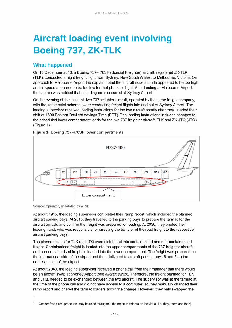
On the evening of the incident, two 737 freighter aircraft, operated by the same freight company, with the same paint scheme, were conducting freight flights into and out of Sydney Airport. The loading supervisor received loading instructions for the two aircraft shortly after they1 started their shift at 1600 Eastern Daylight-savings Time (EDT). The loading instructions included changes to the scheduled lower compartment loads for the two 737 freighter aircraft, TLK and ZK-JTQ (JTQ) (Figure 1).
Figure 1: Boeing 737-476SF lower compartments
Source: Operator, annotated by ATSB
At about 1945, the loading supervisor completed their ramp report, which included the planned aircraft parking bays. At 2015, they travelled to the parking bays to prepare the tarmac for the aircraft arrivals and confirm the freight was prepared for loading. At 2030, they briefed their leading hand, who was responsible for directing the transfer of the road freight to the respective aircraft parking bays.
The planned loads for TLK and JTQ were distributed into containerised and non-containerised freight. Containerised freight is loaded into the upper compartments of the 737 freighter aircraft and non-containerised freight is loaded into the lower compartment. The freight was prepared on the international side of the airport and then delivered to aircraft parking bays 5 and 6 on the domestic side of the airport.
At about 2040, the loading supervisor received a phone call from their manager that there would be an aircraft swap at Sydney Airport (see aircraft swap). Therefore, the freight planned for TLK and JTQ, needed to be exchanged between the two aircraft. The supervisor was at the tarmac at the time of the phone call and did not have access to a computer, so they manually changed their ramp report and briefed the tarmac loaders about the change. However, they only swapped the
1 Gender-free plural pronouns: may be used throughout the report to refer to an individual (i.e. they, them and their).
› 16 ‹
ATSB – AO-2017-002
aircraft registration, flight number and inbound port on their ramp report, they did not change the parking bay numbers. According to the supervisor’s ramp report, TLK was scheduled to park on bay 6 and JTQ on bay 5. However, when the two aircraft arrived at their parking bays, at about 2136 and 2138 respectively, TLK parked on bay 5 and JTQ parked on bay 6.
The staff responsible for loading the containerised freight into the upper compartments of the aircraft loaded the aircraft with reference to their copy of the load instruction report.2 However, the non-containerised lower compartment freight was allocated to the aircraft by the loading supervisor with reference to their ramp report parking bay numbers, which were incorrect. Consequently, TLK was loaded with JTQs lower compartment freight and JTQ was loaded with TLKs lower compartment freight. The flight crew were then issued with the load instruction reports with their planned freight, which were correct for their upper compartments, but incorrect for their lower compartments. The aircraft taxied for departure at 2247 and 2253, and departed at 2300 and 2302 respectively.
Airport curfew While the loading supervisor was supervising the distribution of freight for the aircraft, they were also mindful of the airport curfew time of 2300. The priority for the loading supervisor in this situation is to ensure that the aircraft can depart on time. Therefore, they were required to closely monitor and assess the progress of the loading in order to be prepared to make a decision to stop the loading of freight if it posed a risk of delay past curfew.
Aircraft swap The normal schedule for the two 737 freighter aircraft were as follows:
Flight TFR 21 from Brisbane to Sydney would depart outbound from Sydney as TFR 22 for Melbourne.
Flight TFR 34 from Adelaide to Sydney, would depart outbound from Sydney as TFR 41 for Brisbane.
On the night of the incident, JTQ operated as TFR 21 from Brisbane to Sydney and TLK operated as TFR 34 from Adelaide to Sydney. The aircraft swap in Sydney required JTQ to depart from Sydney as TFR 41 for Brisbane and TLK to depart from Sydney as TFR 22 for Melbourne.
Weight and balance The two 737 freighter aircraft had a maximum take-off weight of 68,039 kg. The centre-of-gravity limits for the aircraft, represented as an ‘index’,3 varied with respect to the weight of the aircraft in a non-linear manner. Table 1 depicts the planned and actual data for TLK and Table 2 depicts the planned and actual data for JTQ. The actual weight and balance for TLK was within limits, but while the weight for JTQ was within limits, the centre of gravity was marginally forward of the forward centre-of-gravity limit.4 The weight and balance calculation is used to provide the aircraft horizontal stabiliser adjustment setting for take-off. The difference between the planned and the actual required stabiliser settings was minimal for both aircraft.
2 The load instruction report (LIR) includes the aircraft registration, flight number, destination and description of planned
load with reference to the respective aircraft upper and lower compartments. The LIR is issued by the load control centre and therefore incorporated all the changes which were communicated to the loading supervisor.
3 ‘Index’ is a number calculated from aircraft weight and centre of gravity position to represent the aircraft moment. The aircraft index is referenced from a point near the centre of gravity and permits simplified centre of gravity calculations when loading the aircraft.
4 A centre of gravity forward of the limits can adversely affect the stability and control of the aircraft.
› 17 ‹
ATSB – AO-2017-002
Table 1: ZK-TLK weight and balance Planned taxi weight 58,178 kg Index 35.1
Actual taxi weight 59,937 kg Index 35.7
Planned landing weight 54,217 kg Index 33.4
Actual landing weight 55,976 kg Index 34.0
Stabiliser adjustment figures:
Planned flaps 1 & 5 4.4 Planned flaps 15 3.6
Actual flaps 1 & 5 4.3 Actual flaps 15 3.6
Table 2: ZK-JTQ weight and balance Planned taxi weight 58,629 kg Index 23.3
Actual taxi weight 56,875 kg Index 22.6
Planned landing weight 54,533 kg Index 23.1
Actual landing weight 52,779 kg Index 22.4
Stabiliser adjustment figures:
Planned flaps 1 & 5 5.0 Planned flaps 15 4.3
Actual flaps 1 & 5 5.1 Actual flaps 15 4.4
Safety analysis Several changes to the planned loading of the aircraft were communicated to the loading supervisor on the afternoon and evening of the incident. The loading supervisor incorporated the initial change to the lower compartment freight into their ramp report and communicated the plan to the staff. When the loading supervisor was notified that an aircraft swap would occur in Sydney, they were on the tarmac and performed a manual update to their ramp report. However, their manual update did not include the change in parking bay numbers.
The loading supervisor referred to their ramp report to direct the loading of the lower compartment freight planned for TLK and JTQ. The staff loading the upper compartments referred to their load instruction reports, which had the correct parking bays. At this time, the supervisor’s attention was divided between the freight loading activities and the overall progress of the loading of both aircraft against the approaching airport curfew time. Consequently, the supervisor directed the planned lower compartment freight for TLK to JTQ, and the planned lower compartment freight for JTQ to TLK.
The pilot of TLK reported that the aircraft’s flight management computer determines the airspeed to be flown on final approach based on aircraft weight. They entered a zero fuel weight into the flight management computer based on the planned load, which was less than the actual load. Therefore the target airspeed flown was slower than required for the actual weight of the aircraft and the aircraft nose attitude increased in order to produce sufficient lift to maintain the approach flight path.
Findings These findings should not be read as apportioning blame or liability to any particular organisation or individual.
• The loading supervisor made a manual change to their ramp report, but did not include a change to the aircraft parking bay numbers; this resulted in them directing the lower compartment freight for TLK to JTQ, and the lower compartment freight for JTQ to TLK.
• JTQ was operated with a centre of gravity marginally forward of the limit.
› 18 ‹
ATSB – AO-2017-002
Safety action Whether or not the ATSB identifies safety issues in the course of an investigation, relevant organisations may proactively initiate safety action in order to reduce their safety risk. The ATSB has been advised of the following proactive safety action in response to this occurrence.
Loading supervisor As a result of this occurrence, the loading supervisor has advised the ATSB that they have taken the following safety actions:
Cross-check During loading of the aircraft lower compartment freight, an independent cross-check will be made of the freight destination against the load instruction report.
Safety message This incident highlights the risk associated with a single source of error propagating through a safety critical process. Following this incident, the loading supervisor reported that the lesson they learned was to have their work cross-checked whenever feasible.
General details Occurrence details
Date and time: 17 December 2016 – 2220 EDT
Occurrence category: Incident
Primary occurrence type: Loading related
Location: Sydney Airport, New South Wales
Latitude: 33° 56.77’ S Longitude: 151° 10.63’ E
Aircraft details Manufacturer and model: The Boeing Company 737-476SF
Registration: ZK-TLK
Serial number: 24434
Type of operation: Air transport high capacity – Freight
Persons on board: Crew – 2 Passengers – 0
Injuries: Crew – 0 Passengers – 0
Aircraft damage: Nil
Aircraft details Manufacturer and model: The Boeing Company 737-476SF
Registration: ZK-JTQ
Serial number: 24442
Type of operation: Air transport high capacity – Freight
Persons on board: Crew – 2 Passengers – 0
Injuries: Crew – 0 Passengers – 0
Aircraft damage: Nil

› 19 ‹
Turboprop aircraft
ATSB – AO-2016-171
› 20 ‹
Engine shut down involving British Aerospace Jetstream 32, VH-OTQ What happened At about 0730 Eastern Daylight-saving Time (EDT) on the 14 December 2016, a Pelican Airlines British Aerospace Jetstream 32 aircraft, registered VH-OTQ (OTQ), departed Newcastle (Williamtown) Airport for Dubbo, New South Wales (NSW). Two flight crew and six passengers were on board the regular public transport flight.
Just after the aircraft reached the cruising altitude of FL 160,1 the captain who was the pilot monitoring,2 noticed the right engine exhaust gas temperature (EGT) gauge was indicating just outside the top of the green arc (650 °C) and was indicating about 655 °C in the yellow arc. The captain reduced the power to the right engine, but there was no corresponding reduction in the EGT.
The flight crew conducted the quick reference handbook (QRH) emergency checklist for the lack of response to power lever movement, which included the engine ignition selected to continuous operation and the engine and airframe ice protection turned on. In accordance with the checklist, the power lever was checked after about 5 minutes and was found to still be unresponsive. The captain indicated that this was very unusual and turned off the engine computers to try to isolate the fault, but this made little difference and so they turned the computers back on. The captain then moved the power lever further back and noticed a momentary increase in EGT, by about 8 °C to 10 °C, as well as an increase in torque.
At this stage of the flight, the aircraft was at a position where they would ordinarily change frequency to a different air traffic controller. However, the flight crew decided to remain on this frequency and return to Newcastle Airport. When the controller instructed the crew to change frequency, the crew advised the controller of their situation and requested a new clearance to return to Newcastle. The crew also advised the controller that as a precaution they might conduct an in-flight engine shut down. The controller gave them a clearance to descend and track direct to Newcastle and subsequently confirmed with the crew that the airport emergency services were required to be available. The controller initiated an alert phase3 and the airport emergency services were requested to be on standby.
The flight crew followed the guidance in the QRH checklist to continue to operate the engine and noted that an engine shut down may be necessary for the approach and landing. As the aircraft was lightly loaded, the captain believed that there would be no issues operating on one engine. The crew conducted the QRH engine in-flight shutdown checklist and shutdown the right engine prior to commencing their descent to Newcastle. The captain briefed the passengers through the aircraft’s public address (PA) system about the precautionary engine shut down and instructed them to familiarise themselves with the passenger safety card.
At about 50 km from Newcastle and on descent passing through about 8,000 ft, the captain became the pilot flying and the first officer the pilot monitoring. They reviewed the QRH abnormal checklist for landing with one engine inoperative. The crew conducted a visual approach and
1 Flight level: at altitudes above 10,000 ft in Australia, an aircraft’s height above mean sea level is referred to as a flight
level (FL). FL 160 equates to 16,000 ft. 2 Pilot Flying (PF) and Pilot Monitoring (PM): procedurally assigned roles with specifically assigned duties at specific
stages of a flight. The PF does most of the flying, except in defined circumstances; such as planning for descent, approach and landing. The PM carries out support duties and monitors the PF’s actions and the aircraft’s flight path.
3 Alert Phase (ALERFA): an emergency phase declared by the air traffic services when apprehension exists as to the safety of the aircraft and its occupants.
ATSB – AO-2016-171
› 21 ‹
landed on runway 30 without further incident. The two crew and six passengers were not injured and the aircraft was not damaged.
Captain’s comment The captain reported that they were flying at a level where icing conditions may be encountered and from previous experience, flying in a different country, it was not uncommon to have an unresponsive power lever control in icing conditions.
The captain reported that they had adequate time to assess the unresponsive power lever, evaluate the performance of the aircraft with only one engine operating and plan for the landing. The workload was not high as they were flying in visual meteorological conditions with adequate time and no other traffic.
On reflection, the captain indicated that although the situation did not appear like an emergency, making a PAN PAN4 call to the controller would have eliminated any uncertainty.
The captain indicated that they had only conducted engine shut downs in a training environment and this was the first time landing with one engine inoperative.
Operator comment The operator reported that the aircraft had been in storage in Australia from 2007 to March 2016. Since March, the aircraft had undergone major maintenance at an aircraft maintenance facility. The right engine involved in the incident had undergone maintenance at an engine overhaul facility and had been preserved during its time of inactivity, prior to its installation on OTQ. The aircraft was release to serviced 11 days (about 26 flight hours) prior to the incident occurring.
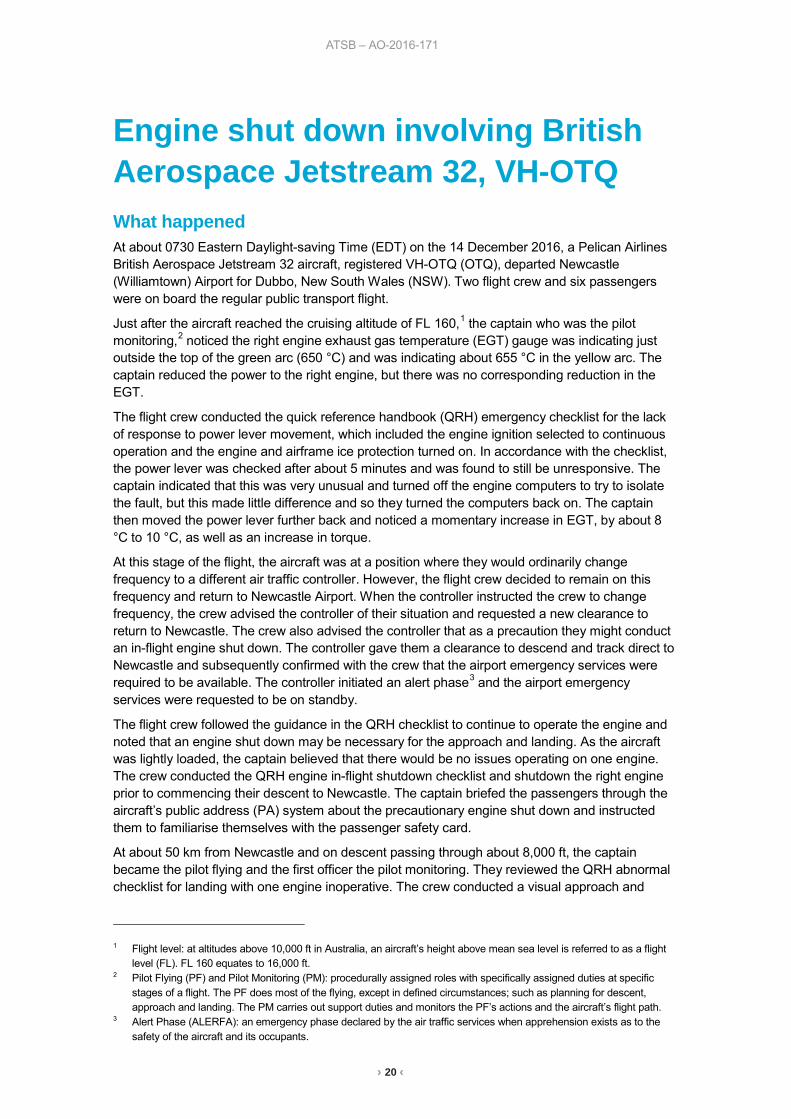
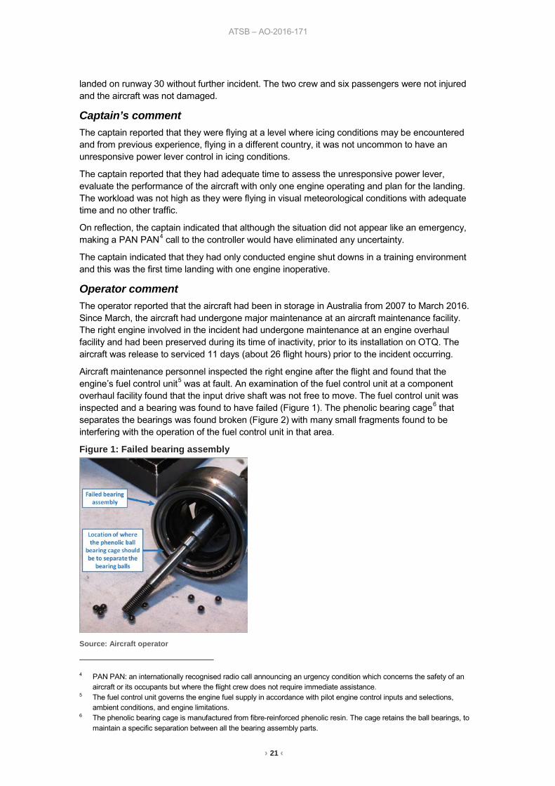
Aircraft maintenance personnel inspected the right engine after the flight and found that the engine’s fuel control unit5 was at fault. An examination of the fuel control unit at a component overhaul facility found that the input drive shaft was not free to move. The fuel control unit was inspected and a bearing was found to have failed (Figure 1). The phenolic bearing cage6 that separates the bearings was found broken (Figure 2) with many small fragments found to be interfering with the operation of the fuel control unit in that area.
Figure 1: Failed bearing assembly
Source: Aircraft operator
4 PAN PAN: an internationally recognised radio call announcing an urgency condition which concerns the safety of an
aircraft or its occupants but where the flight crew does not require immediate assistance. 5 The fuel control unit governs the engine fuel supply in accordance with pilot engine control inputs and selections,
ambient conditions, and engine limitations. 6 The phenolic bearing cage is manufactured from fibre-reinforced phenolic resin. The cage retains the ball bearings, to
maintain a specific separation between all the bearing assembly parts.
ATSB – AO-2016-171
› 22 ‹
Figure 2: Pieces of the failed phenolic bearing cage
Source: Aircraft operator
Findings These findings should not be read as apportioning blame or liability to any particular organisation or individual.
• The engine issue related to a failed fuel control unit bearing, where fragments of the bearing cage interfered with the unit’s operation.
Safety message It is important when time permits to broadcast a ‘pan’ or ‘mayday’, whichever is applicable, to air traffic control to alert the controller and remove any uncertainty about the severity of the situation. If controllers receive a ‘pan’ or ‘mayday’ broadcast, they will organise (depending on the situation) a priority landing to allow an aircraft that might have a problem to land as soon as possible. A situation that seems relatively innocuous can deteriorate quickly. Hesitating or not broadcasting the situation can result in help being delayed.
Airservices Australia defines the two levels of emergency notifications as:
• MAYDAY: My aircraft and its occupants are threatened by grave and imminent danger and/or I require immediate assistance.
• PAN PAN: I have an urgent message to transmit concerning the safety of my aircraft or other vehicle or of some person on board or within sight but I do not require immediate assistance.
Additional information is provided in the following publications:
• Airservices Australia In-flight emergencies, is available from the Airservices website. • Airservices Australia Safety Bulletin 18 July 2016 What happens when I declare an
emergency, is available from the Airservices website.
ATSB – AO-2016-171
› 23 ‹
General details Occurrence details
Date and time: 14 December 2016 – 0748 EDT
Occurrence category: Incident
Primary occurrence type: Technical systems fuel
Location: 60 km WNW of Newcastle Airport, New South Wales
Latitude: 32° 33.13' S Longitude: 151° 15.47' E
Aircraft details – VH-OTQ Manufacturer and model: British Aerospace Jetstream 32
Registration: VH-OTQ
Operator: Pelican Airlines Pty Ltd (operating as FlyPelican)
Serial number: 975
Type of operation: Air transport low capacity - passenger
Persons on board: Crew – 2 Passengers – 6
Injuries: Crew – 0 Passengers – 0
Aircraft damage: Nil
› 24 ‹
ATSB – AO-2017-009
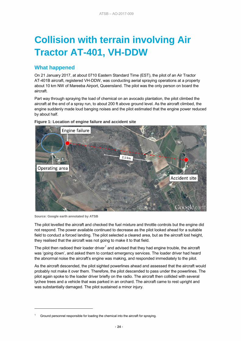
Collision with terrain involving Air Tractor AT-401, VH-DDW What happened On 21 January 2017, at about 0710 Eastern Standard Time (EST), the pilot of an Air Tractor AT-401B aircraft, registered VH-DDW, was conducting aerial spraying operations at a property about 10 km NW of Mareeba Airport, Queensland. The pilot was the only person on board the aircraft.
Part way through spraying the load of chemical on an avocado plantation, the pilot climbed the aircraft at the end of a spray run, to about 200 ft above ground level. As the aircraft climbed, the engine suddenly made loud banging noises and the pilot estimated that the engine power reduced by about half.
Figure 1: Location of engine failure and accident site
Source: Google earth annotated by ATSB
The pilot levelled the aircraft and checked the fuel mixture and throttle controls but the engine did not respond. The power available continued to decrease as the pilot looked ahead for a suitable field to conduct a forced landing. The pilot selected a cleared area, but as the aircraft lost height, they realised that the aircraft was not going to make it to that field.
The pilot then radioed their loader driver1 and advised that they had engine trouble, the aircraft was ‘going down’, and asked them to contact emergency services. The loader driver had heard the abnormal noise the aircraft’s engine was making, and responded immediately to the pilot.
As the aircraft descended, the pilot sighted powerlines ahead and assessed that the aircraft would probably not make it over them. Therefore, the pilot descended to pass under the powerlines. The pilot again spoke to the loader driver briefly on the radio. The aircraft then collided with several lychee trees and a vehicle that was parked in an orchard. The aircraft came to rest upright and was substantially damaged. The pilot sustained a minor injury.
1 Ground personnel responsible for loading the chemical into the aircraft for spraying.
› 25 ‹
ATSB – AO-2017-009
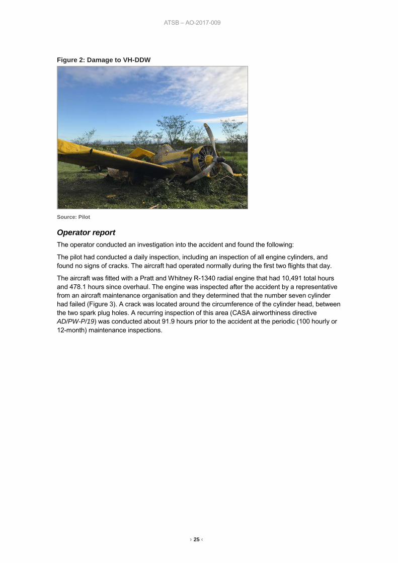
Figure 2: Damage to VH-DDW
Source: Pilot
Operator report The operator conducted an investigation into the accident and found the following:
The pilot had conducted a daily inspection, including an inspection of all engine cylinders, and found no signs of cracks. The aircraft had operated normally during the first two flights that day.
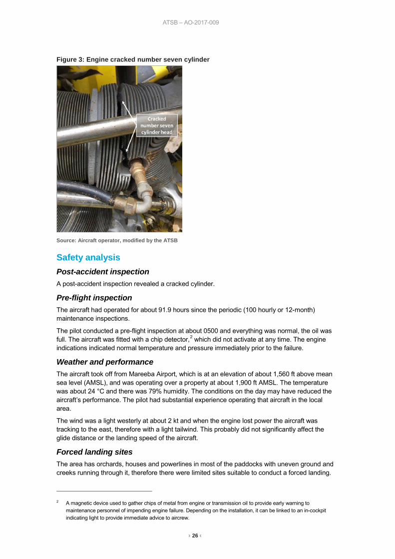
The aircraft was fitted with a Pratt and Whitney R-1340 radial engine that had 10,491 total hours and 478.1 hours since overhaul. The engine was inspected after the accident by a representative from an aircraft maintenance organisation and they determined that the number seven cylinder had failed (Figure 3). A crack was located around the circumference of the cylinder head, between the two spark plug holes. A recurring inspection of this area (CASA airworthiness directive AD/PW-P/19) was conducted about 91.9 hours prior to the accident at the periodic (100 hourly or 12-month) maintenance inspections.
› 26 ‹
ATSB – AO-2017-009
Figure 3: Engine cracked number seven cylinder
Source: Aircraft operator, modified by the ATSB
Safety analysis Post-accident inspection A post-accident inspection revealed a cracked cylinder.
Pre-flight inspection The aircraft had operated for about 91.9 hours since the periodic (100 hourly or 12-month) maintenance inspections.
The pilot conducted a pre-flight inspection at about 0500 and everything was normal, the oil was full. The aircraft was fitted with a chip detector,2 which did not activate at any time. The engine indications indicated normal temperature and pressure immediately prior to the failure.
Weather and performance The aircraft took off from Mareeba Airport, which is at an elevation of about 1,560 ft above mean sea level (AMSL), and was operating over a property at about 1,900 ft AMSL. The temperature was about 24 °C and there was 79% humidity. The conditions on the day may have reduced the aircraft’s performance. The pilot had substantial experience operating that aircraft in the local area.
The wind was a light westerly at about 2 kt and when the engine lost power the aircraft was tracking to the east, therefore with a light tailwind. This probably did not significantly affect the glide distance or the landing speed of the aircraft.
Forced landing sites The area has orchards, houses and powerlines in most of the paddocks with uneven ground and creeks running through it, therefore there were limited sites suitable to conduct a forced landing.
2 A magnetic device used to gather chips of metal from engine or transmission oil to provide early warning to
maintenance personnel of impending engine failure. Depending on the installation, it can be linked to an in-cockpit indicating light to provide immediate advice to aircrew.
› 27 ‹
ATSB – AO-2017-009
The pilot assessed that there was also no suitable road within gliding distance. The accident site was about 2.5 km from where the engine failed.
Chemical load About 750 L of chemical was still on board the aircraft when the engine lost power. The pilot did not dump the load. The pilot commented that it was an oversight rather than a conscious decision not to dump the load. However, they further commented that they were trained to dump the load in the event of engine failure, and would do that in future if faced with a similar situation.
Findings These findings should not be read as apportioning blame or liability to any particular organisation or individual.
• The number seven cylinder cracked, resulting in a loss of power. • The aircraft was operating at low level (below 200 ft AGL) in an area where there were limited
options available to conduct a forced landing.
Safety message In this accident, the time available to manage the engine failure meant that there were few options in regards to the selection of a landing area. The accident highlights the importance of taking positive action and maintaining aircraft control when conducting a forced landing, while being aware of flare energy and aircraft stall speeds.
The Aerial Agricultural Association of Australia advised that there is nearly always an uncertainty about whether to dump the load and they suggest that the only safe rule is ‘if in doubt, dump’. In a high stress situation such as an engine failure where there is limited time, it is important to apply appropriate emergency procedures. To mitigate against the effect of stress compromising memory even in a minor emergency, pilots should have embedded motor programs to handle emergencies in reactive mode.
The pilot was wearing a helmet and commented that although they were ‘flung’ from side to side during the accident sequence, the seatbelt held them firmly in place.
General details Occurrence details
Date and time: 21 January 2017 – 0710 EST
Occurrence category: Accident
Primary occurrence type: Engine failure or malfunction
Location: 10 km NW of Mareeba Airport, Queensland
Latitude: 17° 00.90' S Longitude: 145° 20.65' E
Aircraft details Manufacturer and model: Air Tractor Inc. AT-401
Registration: VH-DDW
Serial number: 401B-0991
Type of operation: Aerial work – aerial agriculture
Persons on board: Crew – 1 Passengers – 0
Injuries: Crew – 1 Minor Passengers – 0
Aircraft damage: Substantial
› 28 ‹
Piston aircraft
› 29 ‹
ATSB – AO-2017-001
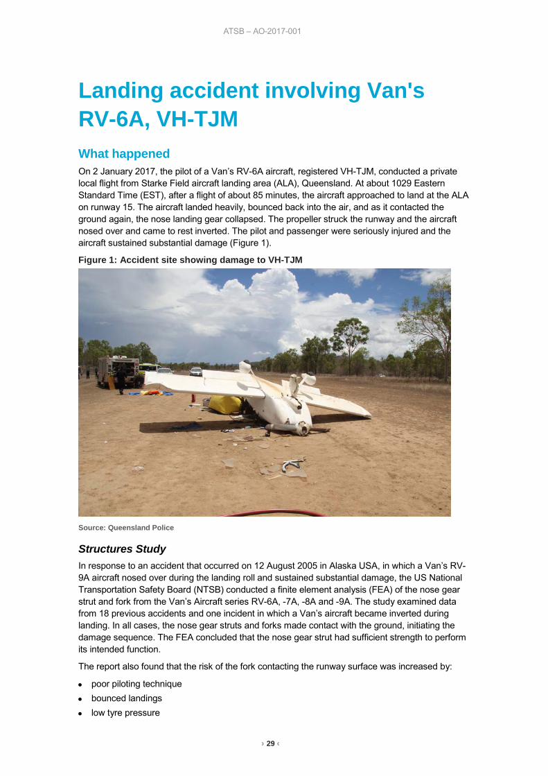
Landing accident involving Van's RV-6A, VH-TJM What happened On 2 January 2017, the pilot of a Van’s RV-6A aircraft, registered VH-TJM, conducted a private local flight from Starke Field aircraft landing area (ALA), Queensland. At about 1029 Eastern Standard Time (EST), after a flight of about 85 minutes, the aircraft approached to land at the ALA on runway 15. The aircraft landed heavily, bounced back into the air, and as it contacted the ground again, the nose landing gear collapsed. The propeller struck the runway and the aircraft nosed over and came to rest inverted. The pilot and passenger were seriously injured and the aircraft sustained substantial damage (Figure 1).
Figure 1: Accident site showing damage to VH-TJM
Source: Queensland Police
Structures Study In response to an accident that occurred on 12 August 2005 in Alaska USA, in which a Van’s RV-9A aircraft nosed over during the landing roll and sustained substantial damage, the US National Transportation Safety Board (NTSB) conducted a finite element analysis (FEA) of the nose gear strut and fork from the Van’s Aircraft series RV-6A, -7A, -8A and -9A. The study examined data from 18 previous accidents and one incident in which a Van’s aircraft became inverted during landing. In all cases, the nose gear struts and forks made contact with the ground, initiating the damage sequence. The FEA concluded that the nose gear strut had sufficient strength to perform its intended function.
The report also found that the risk of the fork contacting the runway surface was increased by:
• poor piloting technique • bounced landings • low tyre pressure
› 30 ‹
ATSB – AO-2017-001
• heavier engine/propeller weights • forward centre of gravity • heavy braking • runway condition – soft or undulating ground, high grass and depressions of objects on the
runway. The aircraft manufacturer subsequently increased the ground clearance of the nose gear fork by about 2.5 cm (1 inch). The Van’s Aircraft service letter in response to the structures study describes the revisions to the nose gear leg design.
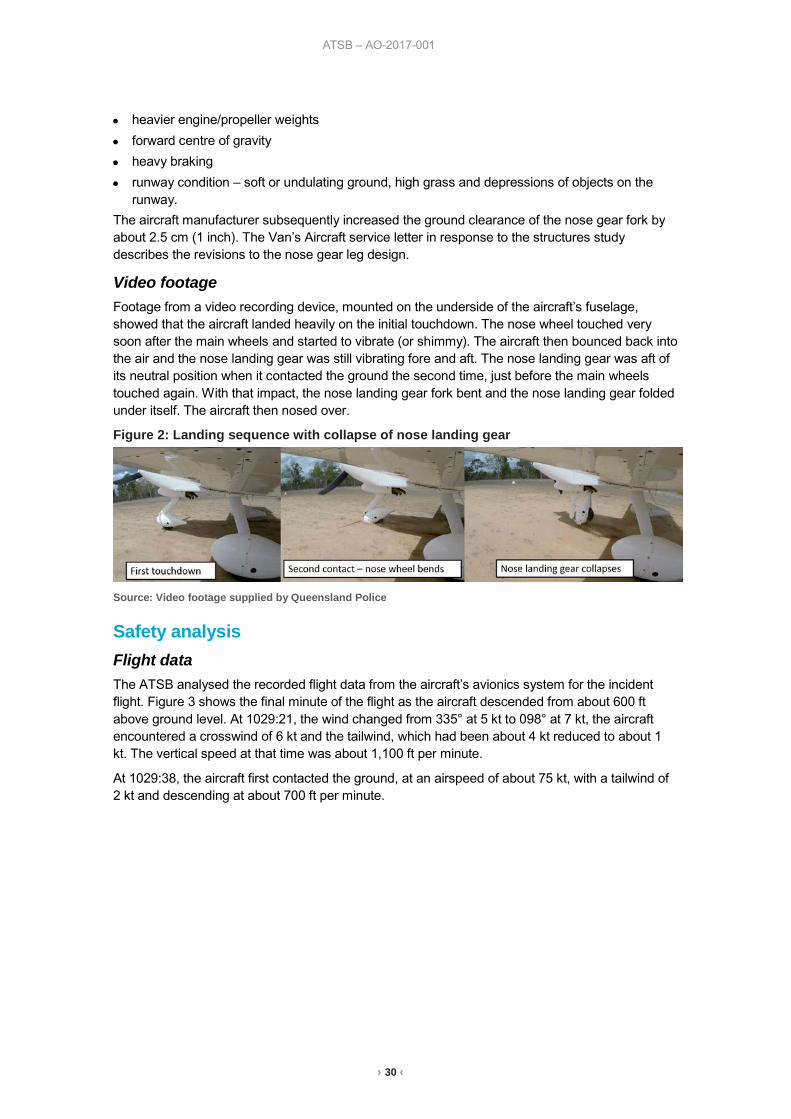
Video footage Footage from a video recording device, mounted on the underside of the aircraft’s fuselage, showed that the aircraft landed heavily on the initial touchdown. The nose wheel touched very soon after the main wheels and started to vibrate (or shimmy). The aircraft then bounced back into the air and the nose landing gear was still vibrating fore and aft. The nose landing gear was aft of its neutral position when it contacted the ground the second time, just before the main wheels touched again. With that impact, the nose landing gear fork bent and the nose landing gear folded under itself. The aircraft then nosed over.
Figure 2: Landing sequence with collapse of nose landing gear
Source: Video footage supplied by Queensland Police
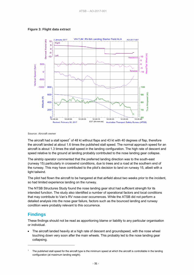
Safety analysis Flight data The ATSB analysed the recorded flight data from the aircraft’s avionics system for the incident flight. Figure 3 shows the final minute of the flight as the aircraft descended from about 600 ft above ground level. At 1029:21, the wind changed from 335° at 5 kt to 098° at 7 kt, the aircraft encountered a crosswind of 6 kt and the tailwind, which had been about 4 kt reduced to about 1 kt. The vertical speed at that time was about 1,100 ft per minute.
At 1029:38, the aircraft first contacted the ground, at an airspeed of about 75 kt, with a tailwind of 2 kt and descending at about 700 ft per minute.
› 31 ‹
ATSB – AO-2017-001
Figure 3: Flight data extract
Source: Aircraft owner
The aircraft had a stall speed1 of 48 kt without flaps and 43 kt with 40 degrees of flap, therefore the aircraft landed at about 1.6 times the published stall speed. The normal approach speed for an aircraft is about 1.3 times the stall speed in the landing configuration. The high rate of descent and speed relative to the ground at landing probably contributed to the nose landing gear collapse.
The airstrip operator commented that the preferred landing direction was to the south-east (runway 15) particularly in crosswind conditions, due to trees and a road at the southern end of the runway. This may have contributed to the pilot’s decision to land on runway 15, albeit with a light tailwind.
The pilot had flown the aircraft to be hangared at that airfield about two weeks prior to the incident, so had limited experience landing on the runway.
The NTSB Structures Study found the nose landing gear strut had sufficient strength for its intended function. The study also identified a number of operational factors and local conditions that may contribute to Van’s RV nose-over occurrences. While the ATSB did not perform a detailed analysis into the nose gear failure, factors such as the bounced landing and runway condition were probably relevant to this occurrence.
Findings These findings should not be read as apportioning blame or liability to any particular organisation or individual.
• The aircraft landed heavily at a high rate of descent and groundspeed, with the nose wheel touching down very soon after the main wheels. This probably led to the nose landing gear collapsing.
1 The published stall speed for the aircraft type is the minimum speed at which the aircraft is controllable in the landing
configuration (at maximum landing weight).
› 32 ‹
ATSB – AO-2017-001
General details Occurrence details
Date and time: 2 January 2017 – 1029 EST
Occurrence category: Accident
Primary occurrence type: Collision with terrain
Location: Starke Field ALA, Queensland
Latitude: 19° 35.20' S Longitude: 146° 46.83' E
Aircraft details Manufacturer and model: Amateur Built Aircraft Van’s RV-6A
Registration: VH-TJM
Serial number: 24498
Type of operation: Private – Pleasure/Travel
Persons on board: Crew – 1 Passengers – 1
Injuries: Crew – 1 Serious Passengers – 1 Serious
Aircraft damage: Substantial

› 33 ‹
Helicopters
› 34 ‹
ATSB – AO-2016-172
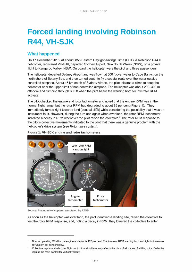
Forced landing involving Robinson R44, VH-SJK What happened On 17 December 2016, at about 0855 Eastern Daylight-savings Time (EDT), a Robinson R44 II helicopter, registered VH-SJK, departed Sydney Airport, New South Wales (NSW), on a private flight to Kangaroo Valley, NSW. On board the helicopter were the pilot and three passengers.
The helicopter departed Sydney Airport and was flown at 500 ft over water to Cape Banks, on the north shore of Botany Bay, and then turned south to fly a coastal route over the water outside controlled airspace. About 16 km south of Sydney Airport, the pilot initiated a climb to keep the helicopter near the upper limit of non-controlled airspace. The helicopter was about 200–300 m offshore and climbing through 650 ft when the pilot heard the warning horn for low rotor RPM activate.
The pilot checked the engine and rotor tachometer and noted that the engine RPM was in the normal flight range, but the rotor RPM had degraded to about 85 per cent (Figure 1).1 They immediately turned right towards land (coastal cliffs) while considering the possibility that it was an instrument fault. However, during the turn and again when over land, the rotor RPM tachometer indicated a decay in RPM whenever the pilot raised the collective.2 The rotor RPM response to the pilot’s collective movements indicated to the pilot that there was a genuine problem with the helicopter’s drive system (see Rotor drive system).
Figure 1: VH-SJK engine and rotor tachometers
Source: Platinum Helicopters, annotated by ATSB
As soon as the helicopter was over land, the pilot identified a landing site, raised the collective to test the rotor RPM response, and, noting a decay in RPM, they lowered the collective to enter
1 Normal operating RPM for the engine and rotor is 102 per cent. The low rotor RPM warning horn and light indicate rotor
RPM at 97 per cent or below. 2 Collective: a primary helicopter flight control that simultaneously affects the pitch of all blades of a lifting rotor. Collective
input is the main control for vertical velocity.
› 35 ‹
ATSB – AO-2016-172
autorotation3 from about 300 ft above ground level at 70 kt. This was about 6–8 seconds after the warning horn activated, at which time the rotor RPM was about 80 per cent. The pilot landed the helicopter with about 7–8 kt forward speed using a standard autorotation flare and cushion technique4 at their chosen landing site. The engine and rotor were still turning after the landing, so the pilot turned off the engine, electrics and fuel cock. The time was about 0910. A mobile phone was used to call rescue services. There were no injuries and the helicopter was substantially damaged.
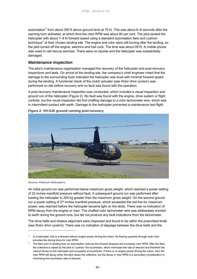
Maintenance inspection The pilot’s maintenance organisation managed the recovery of the helicopter and post-recovery inspections and tests. On arrival at the landing site, the company’s chief engineer noted that the damage to the surrounding bush indicated the helicopter was level with minimal forward speed during the landing. A functional check of the clutch actuator (see Rotor drive system) was performed on site before recovery and no fault was found with the operation.
A post-recovery maintenance inspection was conducted, which included a visual inspection and ground run of the helicopter (Figure 2). No fault was found with the engine, drive system or flight controls, but the visual inspection did find chaffing damage to a rotor tachometer wire, which was in intermittent contact with earth. Damage to the helicopter prevented a maintenance test flight.
Figure 2: VH-SJK ground running post-recovery
Source: Platinum Helicopters
An initial ground run was performed below maximum gross weight, which reached a power setting of 22 inches manifold pressure without fault. A subsequent ground run was performed after loading the helicopter to 200 kg greater than the maximum gross weight. On the second ground run a power setting of 27 inches manifold pressure, which exceeded the red line for maximum power, was reached before the helicopter became light on the skids. There was no indication of RPM decay from the engine or rotor. The chaffed rotor tachometer wire was deliberately shorted to earth during the ground runs, but did not produce any fault indications from the tachometer.
The drive belts and sheave alignment were inspected and found to be within the prescribed limits (see Rotor drive system). There was no indication of slippage between the drive belts and the 3 In a helicopter, this is a descent without engine power driving the rotors. Air flowing upwards through main rotor
provides the driving force for rotor RPM. 4 The flare prior to landing from an autorotation reduces the forward airspeed and increases rotor RPM. After the flare,
the collective is raised by the pilot to ‘cushion’ the touchdown, which minimises the rate of descent and therefore the vertical forces on the helicopter and occupants at touchdown. If there is no engine power driving the rotors, then the rotor RPM will decay when the pilot raises the collective, but the decay in rotor RPM is a secondary consideration to minimising the touchdown rate of descent.
› 36 ‹
ATSB – AO-2016-172
sheaves. During the ground runs, there were no low rotor RPM faults and the low RPM horn activated at 97 per cent rotor tachometer indication, which was the correct setting in accordance with the manufacturer’s specifications. The clutch oil was inspected for metal contamination in accordance with the maintenance manual procedure and no evidence of a defect was found. Following a recommendation from the manufacturer, the maintenance organisation performed a disassembly and examination of the clutch assembly (see Rotor drive system). No defects were found to indicate that the clutch was slipping.
Manufacturer’s comments The pilot operating handbook states that a ‘power failure may be caused by either an engine or drive system failure and will usually be indicated by the low RPM horn.’ The manufacturer reported that the low RPM horn and the rotor tachometer are on ‘completely separate circuits, including the sensors. A failure of both systems simultaneously is extremely unlikely.’ They also noted that the governor is only used to control engine RPM and operates on a separate system with its own sensor. Therefore, the reported fault was not associated with the operation of the governor if the engine RPM remained in the governed range.
The manufacturer noted that some power must have been being delivered to the main rotor, or the rotor RPM would have decayed rapidly before the helicopter entered autorotation. A situation in which the engine was running at normal RPM and the rotor at a low RPM could only occur if there was incomplete transfer of power between the engine and the input to the main rotor gearbox. The two power transmission junctures between the engine and input to the main rotor gearbox are the V-belts and the clutch (see Rotor drive system).
The manufacturer reviewed the maintenance organisation’s photographs of the disassembled clutch assembly and agreed that there was no indication of the clutch slipping at a high power setting.
Rotor drive system The rotors are driven by a V-belt sheave drive system, bolted directly to the crankshaft of the engine (Figure 3). Four, double V-belts (A) transmit power from a lower sheave to an upper sheave (B), which has a clutch in its hub (C). The clutch transmits power forward to the main rotor and aft to the tail rotor. A clutch actuator (D), positioned between the lower and upper sheave, extends to tension the V-belts and prevent slippage.
A clutch caution light is situated at the left end of the row of caution lights at the top of the instrument console. The Robinson R44 II Pilot’s Operating Handbook provided the following explanation for the clutch caution light:
indicates clutch actuator circuit is on, either engaging or disengaging clutch. When switch is in the ENGAGE position, light stays on until belts are properly tensioned. Never take-off before the light goes out.
NOTE: Clutch light may come on momentarily during run-up or during flight to retention belts as they warm-up and stretch slightly. This is normal. If, however, the light flickers or comes on inflight and does not go out within 10 seconds, pull CLUTCH circuit breaker and land as soon as practical. Reduce power and land immediately if there are other indications of drive system failure (be prepared to enter autorotation). Inspect drive system for a possible malfunction.
The pilot observed the clutch light operation before take-off to be serviceable. However, they did not notice the clutch light during the emergency and therefore could not confirm if it activated. Their attention during the emergency was focussed on the rotor RPM, airspeed and identifying an emergency landing site.
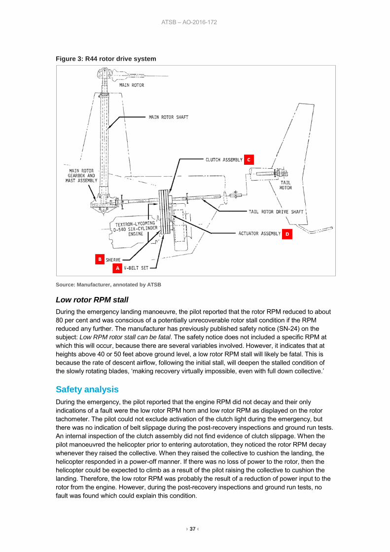
› 37 ‹
ATSB – AO-2016-172
Figure 3: R44 rotor drive system
Source: Manufacturer, annotated by ATSB
Low rotor RPM stall During the emergency landing manoeuvre, the pilot reported that the rotor RPM reduced to about 80 per cent and was conscious of a potentially unrecoverable rotor stall condition if the RPM reduced any further. The manufacturer has previously published safety notice (SN-24) on the subject: Low RPM rotor stall can be fatal. The safety notice does not included a specific RPM at which this will occur, because there are several variables involved. However, it indicates that at heights above 40 or 50 feet above ground level, a low rotor RPM stall will likely be fatal. This is because the rate of descent airflow, following the initial stall, will deepen the stalled condition of the slowly rotating blades, ‘making recovery virtually impossible, even with full down collective.’
Safety analysis During the emergency, the pilot reported that the engine RPM did not decay and their only indications of a fault were the low rotor RPM horn and low rotor RPM as displayed on the rotor tachometer. The pilot could not exclude activation of the clutch light during the emergency, but there was no indication of belt slippage during the post-recovery inspections and ground run tests. An internal inspection of the clutch assembly did not find evidence of clutch slippage. When the pilot manoeuvred the helicopter prior to entering autorotation, they noticed the rotor RPM decay whenever they raised the collective. When they raised the collective to cushion the landing, the helicopter responded in a power-off manner. If there was no loss of power to the rotor, then the helicopter could be expected to climb as a result of the pilot raising the collective to cushion the landing. Therefore, the low rotor RPM was probably the result of a reduction of power input to the rotor from the engine. However, during the post-recovery inspections and ground run tests, no fault was found which could explain this condition.
› 38 ‹
ATSB – AO-2016-172
ATSB comment The ATSB notes that the pilot operating handbook directs the pilot to lower the collective immediately to maintain rotor RPM between 97 and 108 per cent, following a power failure. In this case the pilot elected to delay recovering RPM until they could reach a safe landing site, since immediately lowering collective would have resulted in ditching the helicopter in the ocean.
Findings These findings should not be read as apportioning blame or liability to any particular organisation or individual.
• The low rotor RPM was probably the result of a reduction in power input to the rotor from the engine, but the fault could not be reproduced during post-recovery tests.
• There was no evidence of clutch slippage occurring at a high power setting from the disassembly and inspection of the clutch assembly.
Safety message The pilot reported that their lesson learned following this emergency was the importance of training and professional development. Although they only used their helicopter for private flights, they trained for a commercial helicopter licence to improve their knowledge and skill in handling their helicopter. They did not believe they could have flown a successful emergency landing without their previous recurrent proficiency training in practice autorotations.
General details Occurrence details
Date and time: 17 December 2016 – 0910 EST
Occurrence category: Accident
Primary occurrence type: Forced landing
Location: 16 km south of Sydney Airport, New South Wales
Latitude: 34° 05.85’ S Longitude: 151° 09.40’ E
Aircraft details Manufacturer and model: Robinson Helicopter Company R44 II
Registration: VH-SJK
Serial number: 12174
Type of operation: Private – pleasure / travel
Persons on board: Crew – 1 Passengers – 3
Injuries: Crew – 0 Passengers – 0
Aircraft damage: Substantial

› 39 ‹
Unmanned aircraft
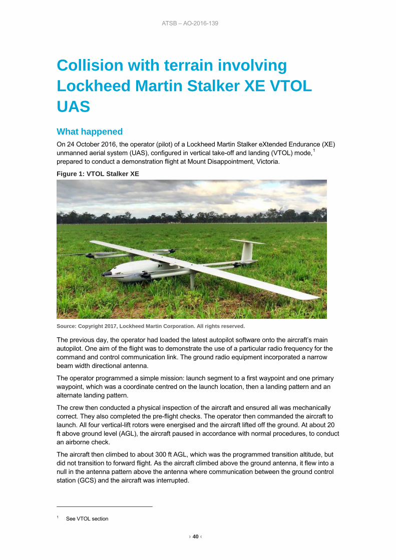
ATSB – AO-2016-139
› 40 ‹
Collision with terrain involving Lockheed Martin Stalker XE VTOL UAS What happened On 24 October 2016, the operator (pilot) of a Lockheed Martin Stalker eXtended Endurance (XE) unmanned aerial system (UAS), configured in vertical take-off and landing (VTOL) mode,1 prepared to conduct a demonstration flight at Mount Disappointment, Victoria.
Figure 1: VTOL Stalker XE
Source: Copyright 2017, Lockheed Martin Corporation. All rights reserved.
The previous day, the operator had loaded the latest autopilot software onto the aircraft’s main autopilot. One aim of the flight was to demonstrate the use of a particular radio frequency for the command and control communication link. The ground radio equipment incorporated a narrow beam width directional antenna.
The operator programmed a simple mission: launch segment to a first waypoint and one primary waypoint, which was a coordinate centred on the launch location, then a landing pattern and an alternate landing pattern.
The crew then conducted a physical inspection of the aircraft and ensured all was mechanically correct. They also completed the pre-flight checks. The operator then commanded the aircraft to launch. All four vertical-lift rotors were energised and the aircraft lifted off the ground. At about 20 ft above ground level (AGL), the aircraft paused in accordance with normal procedures, to conduct an airborne check.
The aircraft then climbed to about 300 ft AGL, which was the programmed transition altitude, but did not transition to forward flight. As the aircraft climbed above the ground antenna, it flew into a null in the antenna pattern above the antenna where communication between the ground control station (GCS) and the aircraft was interrupted.
1 See VTOL section
ATSB – AO-2016-139
› 41 ‹
The aircraft hovered and, after about five minutes, the operator commanded ‘abort’ from the GCS. At that time, the operator observed that communication with the aircraft had been lost and repositioned the antenna to point directly at the aircraft. After observing continued lost link indications for about 30 seconds, the operator enabled the alternate radio datalink, restoring communication with the aircraft. However, the previously selected ‘abort’ command was unavailable for re-issue after the initial selection.
About 11 minutes after launch, the aircraft’s power failed, the vertical propellers stopped, and the aircraft pitched about 95 degrees nose down, descended vertically and collided with the ground.
The aircraft sustained substantial damage.
Vertical take-off and landing (VTOL) configuration In the VTOL configuration, four vertical lift motors are provided in addition to a conventional tractor motor/propeller. The aircraft takes off vertically and then transitions to horizontal flight at a set altitude. Following the period of horizontal (fixed-wing) flight, the aircraft transitions back to vertical flight for landing.
Transition altitude The typical time needed to climb to departure altitude and transition to forward flight is less than 1 minute.
The transition altitude is specified by the operator and is usually 150-200 ft higher than any nearby obstacles. In this incident, the operator had selected 300 ft due to trees about 100 ft high in the vicinity. The lower the transition altitude, the less time is required in the VTOL configuration, which requires substantially more power (and therefore battery) than the more efficient forward flight.
Post-accident inspection Following the accident, an inspection revealed that the aircraft’s negative main power cable was unsoldered and had separated from its pin in the main power connector, which was plugged into the aircraft’s battery. The operator’s investigation found that the connector had failed before the aircraft battery drained.
Loss of electrical power The wiring in the VTOL aircraft configuration was designed to supply vertical climb power for 2 minutes and the system had been validation-tested for 3 minutes at that power setting. The battery connector wiring in the accident aircraft failed 11 minutes into flight, resulting in total loss of electrical power and loss of aircraft control.
Flight data According to the recorded flight data, the data link was interrupted about 1 minute and 20 seconds after launch. Two seconds later, an aircraft software lost-link contingency response automatically issued a command to latch the current altitude command, navigate to the launch point, descend and land.
However, 1 second after the lost link contingency command was issued, an additional spurious command was issued. This inappropriate spurious command caused the aircraft to remain in an extended hover and prevented the operator from further affecting aircraft operation, even after re-establishing data link communications. Extended operations at hover power, well beyond electrical power supply system design limits, overheated the wiring and resulted in a connector failure causing interruption of the battery power supply and subsequent loss of aircraft control.
Software error The system manufacturer found that an inappropriate spurious command issued by the aircraft software was due to a coding error in the VTOL software that had not been detected during testing.
ATSB – AO-2016-139
› 42 ‹
Communications Communication between the GCS and aircraft is not required for flight. If communication between the GCS and aircraft is lost during flight, the autopilot continues to fly the aircraft according to programmed contingency logic. If communications are lost for more than 5 seconds during the VTOL launch phase, contingency logic commands the aircraft to return to the launch point, descend and land.
Landing/emergency command options Having commanded ‘abort’, the operator thought that the command would continue to be sent to the aircraft after communications were restored until the aircraft acknowledged receipt of the command. This did not occur. In the launch phase, the ‘abort’ command should cause the aircraft to navigate to the launch point and descend vertically to the ground.
No other appropriate commands were available to the operator.
Findings These findings should not be read as apportioning blame or liability to any particular organisation or individual.
• Communication between the GCS and aircraft was lost for about 5.5 minutes during the launch phase, due to the aircraft flying into the null in the antenna pattern above the antenna.
• A return to launch command was issued by the autopilot due to loss of communications, but was not completed, because a spurious command was issued due to a coding error.
• After 11 minutes at vertical climb power, the high current overheated the wiring. The heat unsoldered the negative main power cable resulting in a total loss of electrical power.
• The total loss of power resulted in a loss of control and the aircraft collided with the ground.
Safety action Whether or not the ATSB identifies safety issues in the course of an investigation, relevant organisations may proactively initiate safety action in order to reduce their safety risk. The ATSB has been advised of the following safety action in response to this occurrence.
UAS manufacturer As a result of this occurrence, Lockheed Martin has advised the ATSB that they are taking the following safety actions:
Software redesign The software is undergoing testing, redesign and a review of contingency management in VTOL modes.
Safety message This occurrence highlights the importance of UAS software testing to cover potential non-normal scenarios prior to release into operation.
ATSB – AO-2016-139
› 43 ‹
General details Occurrence details
Date and time: 24 October 2016 – 1232 EDT
Occurrence category: Accident
Primary occurrence type: Collision with terrain
Location: Mount Disappointment, Victoria
Latitude: 37° 33.50' S Longitude: 145° 16.37' E
Aircraft details Manufacturer and model: Lockheed Martin Skunk Works Stalker XE VTOL
Serial number: 243
Type of operation: Aerial work – Other
Aircraft damage: Substantial
› 44 ‹
Separation issues
ATSB – AO-2016-173
› 45 ‹
Call sign confusion involving Airbus A330, VH-EBA, and Boeing 737, VH-VXF What happened On 15 December 2016, an Airbus A330-202 aircraft, registered VH-EBA and operating Qantas Flight (QF) 652, was on descent to Brisbane Airport, Queensland, arriving from the south-west from Perth, Western Australia. QF652 was sequenced to follow another Qantas Airbus A330-303 aircraft, registered VH-QPG and operating QF62, which was also on descent to Brisbane Airport, but arriving from the north-west from Narita, Japan.
For noise abatement, reciprocal runway operations were in progress at Brisbane, with arriving aircraft landing on runway 19, and departing aircraft taking off from runway 01.
At 0516:25 Eastern Standard Time (EST), the approach controller cleared QF62 to descend to 5,000 ft.
At 0517:55, a Qantas Boeing 737-838 aircraft, registered VH-VXF and operating QF601, (departing Brisbane for Melbourne, Victoria) took off from runway 01 and was tracking to the southwest. At 0519:15, the approach controller cleared QF601 to climb to 8,000 ft.
Five seconds later, the approach controller cleared QF652 to descend to 9,000 ft for separation with QF601 travelling in the opposite direction. The controller advised the crew of QF652 that they would be cleared for further descent once they had passed opposite direction traffic. The controller then also advised the flight crew of QF601 that there would be a short delay at 8,000 ft due to opposite direction traffic above.
At 0520:20, the controller inadvertently cleared QF652 (instead of QF62) to descend to 2,500 ft and conduct an ILS approach to runway 19. The crew of QF652, still on descent to 9,000 ft, read back the clearance and set their assigned altitude to 2,500 ft (which was normal procedure having been cleared for the descent). The crew sighted the opposite direction aircraft out to their right, and continued their descent.
About 30 seconds later, the air traffic system identified a discrepancy between the controller-cleared flight level of 9,000 ft and the flight crew-entered altitude of 2,500 ft. The controller received a predicted level mismatch (PLM) alert, which displays as ‘cleared flight level (CFL?)’.1 The controller asked the crew of QF652 to confirm they were maintaining 9,000 ft, and the crew responded that they were on descent to 2,500 ft as cleared. The aircraft was passing 9,200 ft at this stage. The controller immediately responded ‘no, that was for Qantas 62, Qantas 652 maintain 9,000’. By that time, radar data indicated that QF62 was at 4,900 ft. No read back was heard from the crew of QF62 to the clearance inadvertently issued to QF652.
The flight crew of QF652 reported that they were passing about 8,600 ft, when the controller instructed them to maintain 9,000. The crew stopped the descent and climbed the aircraft back up to 9,000 ft. The crew received a traffic alert2 for about 5 seconds on the reciprocal aircraft. At 0521:19, the controller cleared the flight crew of QF652 to descend to 8,000 ft and the aircraft subsequently conducted a normal approach to Brisbane.
1 The PLM alert will display when there is a system-detected difference between the controller-entered CFL and the
altitude/level entered by the pilot into the aircraft’s control systems (from suitably equipped aircraft – with mode S transponder).
2 Traffic advisory (TA): an alert issued by the traffic alert and collision avoidance system (TCAS) when the detected traffic may result in a conflict. Pilots are expected to initiate a visual search for the traffic causing the TA.
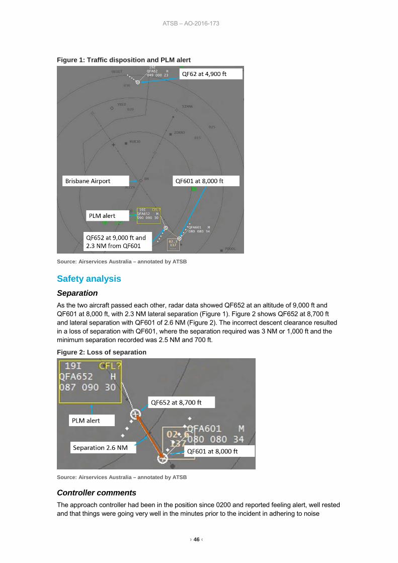
ATSB – AO-2016-173
› 46 ‹
Figure 1: Traffic disposition and PLM alert
Source: Airservices Australia – annotated by ATSB
Safety analysis Separation As the two aircraft passed each other, radar data showed QF652 at an altitude of 9,000 ft and QF601 at 8,000 ft, with 2.3 NM lateral separation (Figure 1). Figure 2 shows QF652 at 8,700 ft and lateral separation with QF601 of 2.6 NM (Figure 2). The incorrect descent clearance resulted in a loss of separation with QF601, where the separation required was 3 NM or 1,000 ft and the minimum separation recorded was 2.5 NM and 700 ft.
Figure 2: Loss of separation
Source: Airservices Australia – annotated by ATSB
Controller comments The approach controller had been in the position since 0200 and reported feeling alert, well rested and that things were going very well in the minutes prior to the incident in adhering to noise
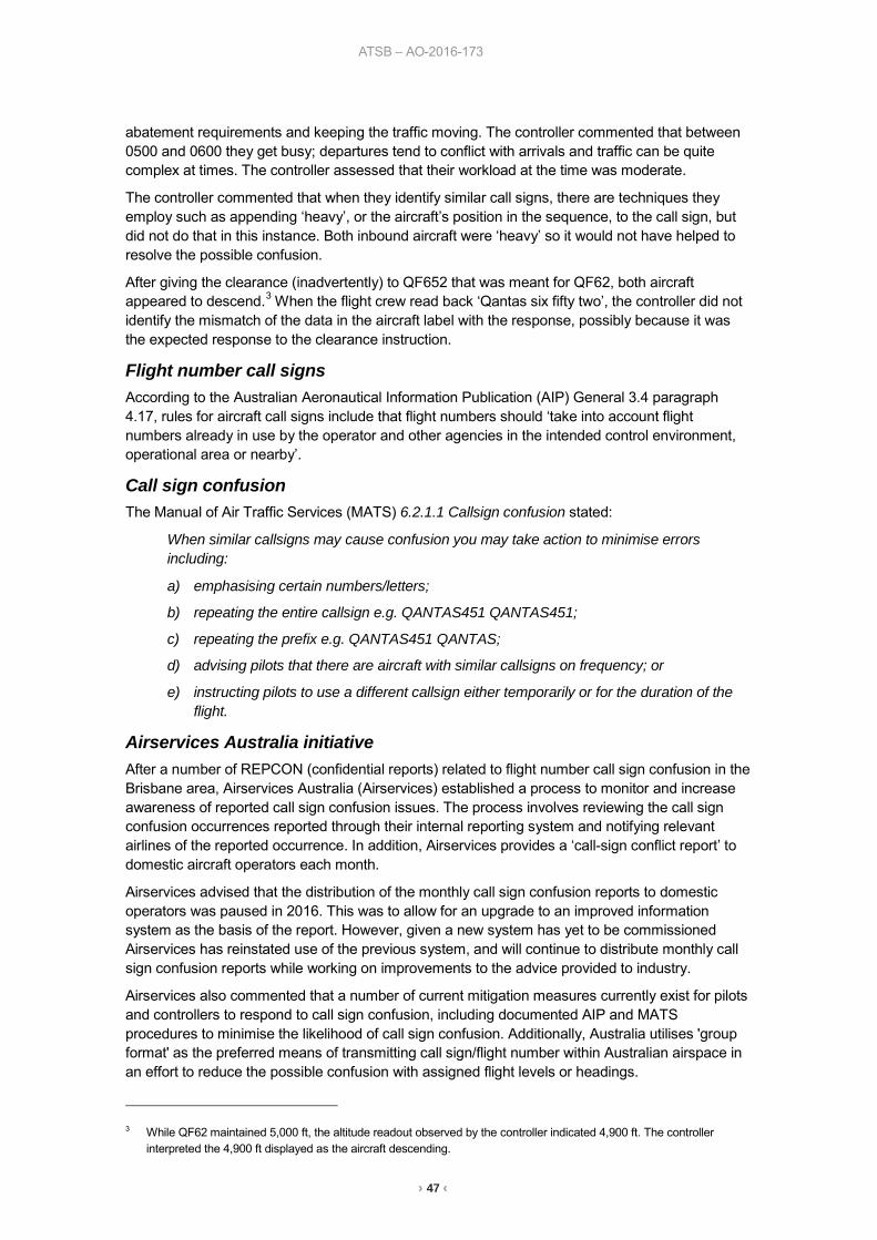
ATSB – AO-2016-173
› 47 ‹
abatement requirements and keeping the traffic moving. The controller commented that between 0500 and 0600 they get busy; departures tend to conflict with arrivals and traffic can be quite complex at times. The controller assessed that their workload at the time was moderate.
The controller commented that when they identify similar call signs, there are techniques they employ such as appending ‘heavy’, or the aircraft’s position in the sequence, to the call sign, but did not do that in this instance. Both inbound aircraft were ‘heavy’ so it would not have helped to resolve the possible confusion.
After giving the clearance (inadvertently) to QF652 that was meant for QF62, both aircraft appeared to descend.3 When the flight crew read back ‘Qantas six fifty two’, the controller did not identify the mismatch of the data in the aircraft label with the response, possibly because it was the expected response to the clearance instruction.
Flight number call signs According to the Australian Aeronautical Information Publication (AIP) General 3.4 paragraph 4.17, rules for aircraft call signs include that flight numbers should ‘take into account flight numbers already in use by the operator and other agencies in the intended control environment, operational area or nearby’.
Call sign confusion The Manual of Air Traffic Services (MATS) 6.2.1.1 Callsign confusion stated:
When similar callsigns may cause confusion you may take action to minimise errors including:
a) emphasising certain numbers/letters;
b) repeating the entire callsign e.g. QANTAS451 QANTAS451;
c) repeating the prefix e.g. QANTAS451 QANTAS;
d) advising pilots that there are aircraft with similar callsigns on frequency; or
e) instructing pilots to use a different callsign either temporarily or for the duration of the flight.
Airservices Australia initiative After a number of REPCON (confidential reports) related to flight number call sign confusion in the Brisbane area, Airservices Australia (Airservices) established a process to monitor and increase awareness of reported call sign confusion issues. The process involves reviewing the call sign confusion occurrences reported through their internal reporting system and notifying relevant airlines of the reported occurrence. In addition, Airservices provides a ‘call-sign conflict report’ to domestic aircraft operators each month.
Airservices advised that the distribution of the monthly call sign confusion reports to domestic operators was paused in 2016. This was to allow for an upgrade to an improved information system as the basis of the report. However, given a new system has yet to be commissioned Airservices has reinstated use of the previous system, and will continue to distribute monthly call sign confusion reports while working on improvements to the advice provided to industry.
Airservices also commented that a number of current mitigation measures currently exist for pilots and controllers to respond to call sign confusion, including documented AIP and MATS procedures to minimise the likelihood of call sign confusion. Additionally, Australia utilises 'group format' as the preferred means of transmitting call sign/flight number within Australian airspace in an effort to reduce the possible confusion with assigned flight levels or headings.
3 While QF62 maintained 5,000 ft, the altitude readout observed by the controller indicated 4,900 ft. The controller
interpreted the 4,900 ft displayed as the aircraft descending.
ATSB – AO-2016-173
› 48 ‹
Findings These findings should not be read as apportioning blame or liability to any particular organisation or individual.
• The controller inadvertently assigned descent to QF652 instead of QF62 due to call sign confusion, resulting in a loss of separation with QF601.
• The two inbound aircraft were operating on the same frequency with similar call signs and call sign confusion mitigation strategies were not used by air traffic control.
ATSB comment According to the article Callsign Confusion, the US Aviation Safety Reporting System (ASRS) receives a large number of reports of call sign confusion, some of which result in losses of separation. The article states that communications technique is pilots’ and air traffic controllers’ primary defence against confusion and that they need to continue to bring call sign problems to the attention of management.
The Skybrary article Call-sign confusion lists contributory factors including:
• failure of operator to give sufficient consideration in allocation of call signs • pilot and controller workload • interruption or distraction • airspace and procedure design • traffic density.
Safety message Air traffic control and flight crew need to be vigilant when they identify the potential for call sign confusion.
Flight numbers are assigned by airlines, some of which operate call sign de-confliction programmes. The ATSB encourages aircraft operators to use these strategies to help prevent similar incidents occurring. Air traffic control is encouraged to consider liaising with airlines to enhance call sign de-confliction programmes.
ATSB – AO-2016-173
› 49 ‹
General details Occurrence details
Date and time: 15 December 2016 – 0517 EST
Occurrence category: Incident
Primary occurrence type: Loss of separation
Location: near Brisbane Airport, Queensland
Latitude: 27° 23.05' S Longitude: 153° 07.05' E
Aircraft details: VH-EBA Manufacturer and model: Airbus A330
Registration: VH-EBA
Operator: Qantas Airways
Serial number: 0508
Type of operation: Air transport high capacity – Passenger
Persons on board: Crew – Unknown Passengers – Unknown
Injuries: Crew – 0 Passengers – 0
Aircraft damage: Nil
Aircraft details: VH-VXF Manufacturer and model: The Boeing Company 737
Registration: VH-VXF
Operator: Qantas Airways
Serial number: 29553
Type of operation: Air transport high capacity – Passenger
Persons on board: Crew – Unknown Passengers – Unknown
Injuries: Crew – 0 Injuries – 0
Aircraft damage: Nil
› 50 ‹
Australian Transport Safety Bureau The Australian Transport Safety Bureau (ATSB) is an independent Commonwealth Government statutory agency. The Bureau is governed by a Commission and is entirely separate from transport regulators, policy makers and service providers. The ATSB’s function is to improve safety and public confidence in the aviation, marine and rail modes of transport through excellence in: independent investigation of transport accidents and other safety occurrences; safety data recording, analysis and research; fostering safety awareness, knowledge and action.
The ATSB is responsible for investigating accidents and other transport safety matters involving civil aviation, marine and rail operations in Australia that fall within Commonwealth jurisdiction, as well as participating in overseas investigations involving Australian registered aircraft and ships. A primary concern is the safety of commercial transport, with particular regard to fare-paying passenger operations.
The ATSB performs its functions in accordance with the provisions of the Transport Safety Investigation Act 2003 and Regulations and, where applicable, relevant international agreements.
Purpose of safety investigations The object of a safety investigation is to identify and reduce safety-related risk. ATSB investigations determine and communicate the safety factors related to the transport safety matter being investigated. The terms the ATSB uses to refer to key safety and risk concepts are set out in the next section: Terminology Used in this Report.
It is not a function of the ATSB to apportion blame or determine liability. At the same time, an investigation report must include factual material of sufficient weight to support the analysis and findings. At all times the ATSB endeavours to balance the use of material that could imply adverse comment with the need to properly explain what happened, and why, in a fair and unbiased manner.
About this Bulletin
The ATSB receives around 15,000 notifications of Aviation occurrences each year, 8,000 of which are accidents, serious incidents and incidents. It also receives a lesser number of similar occurrences in the Rail and Marine transport sectors. It is from the information provided in these notifications that the ATSB makes a decision on whether or not to investigate. While some further information is sought in some cases to assist in making those decisions, resource constraints dictate that a significant amount of professional judgement is needed to be exercised.
There are times when more detailed information about the circumstances of the occurrence allows the ATSB to make a more informed decision both about whether to investigate at all and, if so, what necessary resources are required (investigation level). In addition, further publically available information on accidents and serious incidents increases safety awareness in the industry and enables improved research activities and analysis of safety trends, leading to more targeted safety education.
The Short Investigation Team gathers additional factual information on aviation accidents and serious incidents (with the exception of 'high risk operations), and similar Rail and Marine occurrences, where the initial decision has been not to commence a 'full' (level 1 to 4) investigation.
The primary objective of the team is to undertake limited-scope, fact gathering investigations, which result in a short summary report. The summary report is a compilation of the information the ATSB has gathered, sourced from individuals or organisations involved in the occurrences, on the circumstances surrounding the occurrence and what safety action may have been taken or identified as a result of the occurrence.

› 51 ‹
These reports are released publically. In the aviation transport context, the reports are released periodically in a Bulletin format.
Conducting these Short investigations has a number of benefits:
• Publication of the circumstances surrounding a larger number of occurrences enables greater industry awareness of potential safety issues and possible safety action.
• The additional information gathered results in a richer source of information for research and statistical analysis purposes that can be used both by ATSB research staff as well as other stakeholders, including the portfolio agencies and research institutions.
• Reviewing the additional information serves as a screening process to allow decisions to be made about whether a full investigation is warranted. This addresses the issue of 'not knowing what we don't know' and ensures that the ATSB does not miss opportunities to identify safety issues and facilitate safety action.
• In cases where the initial decision was to conduct a full investigation, but which, after the preliminary evidence collection and review phase, later suggested that further resources are not warranted, the investigation may be finalised with a short factual report.
• It assists Australia to more fully comply with its obligations under ICAO Annex 13 to investigate all aviation accidents and serious incidents.
• Publicises Safety Messages aimed at improving awareness of issues and good safety practices to both the transport industries and the travelling public.
AT
SB
Transp
ort S
afety Rep
ort
Aviation S
hort Investigations
Aviation S
hort Investigations Bulletin Issue 59
AB
-2017-036 Final – 27 A
pril 2017
Investigatio
n
Australian Transport Safety Bureau
Enquiries 1800 020 616Notifications 1800 011 034REPCON 1800 011 034Web www.atsb.gov.auTwitter @ATSBinfoEmail [email protected] Facebook atsbgovau