inrow rd 100-series and inrow rd 200-series user’s …€¦ · 1 inrow rd 100-series and inrow rd...
TRANSCRIPT
User’s Guide
InRow RD 100-SeriesInRow RD 200-Series
ACRD100, ACRD101ACRD200, ACRD201

Contents
Introduction ..................................................................... 1Product Description . . . . . . . . . . . . . . . . . . . . . . . . . . . . . . . . . . . . . . . 1
Features . . . . . . . . . . . . . . . . . . . . . . . . . . . . . . . . . . . . . . . . . . . . . . . . 1Initial setup . . . . . . . . . . . . . . . . . . . . . . . . . . . . . . . . . . . . . . . . . . . . . 1Network management features . . . . . . . . . . . . . . . . . . . . . . . . . . . . . 2
Internal Management Features . . . . . . . . . . . . . . . . . . . . . . . . . . . . . . 2Overview . . . . . . . . . . . . . . . . . . . . . . . . . . . . . . . . . . . . . . . . . . . . . . . 2Access priority for logging on . . . . . . . . . . . . . . . . . . . . . . . . . . . . . . 2Types of user accounts . . . . . . . . . . . . . . . . . . . . . . . . . . . . . . . . . . . 2
How to Recover from a Lost Password . . . . . . . . . . . . . . . . . . . . . . . 3
Status and Link RX/TX LEDs . . . . . . . . . . . . . . . . . . . . . . . . . . . . . . . . 4Status LED . . . . . . . . . . . . . . . . . . . . . . . . . . . . . . . . . . . . . . . . . . . . . . 4Link-RX/TX (10/100) LED . . . . . . . . . . . . . . . . . . . . . . . . . . . . . . . . . . 4
Watchdog Features. . . . . . . . . . . . . . . . . . . . . . . . . . . . . . . . . . . . . . . . 5Overview . . . . . . . . . . . . . . . . . . . . . . . . . . . . . . . . . . . . . . . . . . . . . . . 5Network interface watchdog mechanism . . . . . . . . . . . . . . . . . . . . . 5Resetting the network timer . . . . . . . . . . . . . . . . . . . . . . . . . . . . . . . 5
Control Console .............................................................. 6How To Log On . . . . . . . . . . . . . . . . . . . . . . . . . . . . . . . . . . . . . . . . . . . 6
Overview . . . . . . . . . . . . . . . . . . . . . . . . . . . . . . . . . . . . . . . . . . . . . . . 6Remote access to the control console . . . . . . . . . . . . . . . . . . . . . . . 6Local access to the control console . . . . . . . . . . . . . . . . . . . . . . . . . 7
Main Screen. . . . . . . . . . . . . . . . . . . . . . . . . . . . . . . . . . . . . . . . . . . . . . 7Sample main screen . . . . . . . . . . . . . . . . . . . . . . . . . . . . . . . . . . . . . . 7Information and status fields . . . . . . . . . . . . . . . . . . . . . . . . . . . . . . . 7
InRow RD 100-Series and InRow RD 200-Series User’s Guide i

Control Console Menus . . . . . . . . . . . . . . . . . . . . . . . . . . . . . . . . . . . . 9Overview . . . . . . . . . . . . . . . . . . . . . . . . . . . . . . . . . . . . . . . . . . . . . . . . 9How to use control console menus . . . . . . . . . . . . . . . . . . . . . . . . . . 9Control console structure . . . . . . . . . . . . . . . . . . . . . . . . . . . . . . . . . . 9Main menu . . . . . . . . . . . . . . . . . . . . . . . . . . . . . . . . . . . . . . . . . . . . . . 9Device Manager menu . . . . . . . . . . . . . . . . . . . . . . . . . . . . . . . . . . . . . 9Network menu . . . . . . . . . . . . . . . . . . . . . . . . . . . . . . . . . . . . . . . . . . 10System menu . . . . . . . . . . . . . . . . . . . . . . . . . . . . . . . . . . . . . . . . . . . 10
Web Interface................................................................. 11Introduction. . . . . . . . . . . . . . . . . . . . . . . . . . . . . . . . . . . . . . . . . . . . . 11
Overview . . . . . . . . . . . . . . . . . . . . . . . . . . . . . . . . . . . . . . . . . . . . . . . 11Supported Web browsers . . . . . . . . . . . . . . . . . . . . . . . . . . . . . . . . . 11
How to Log On . . . . . . . . . . . . . . . . . . . . . . . . . . . . . . . . . . . . . . . . . . 11Overview . . . . . . . . . . . . . . . . . . . . . . . . . . . . . . . . . . . . . . . . . . . . . . . 11URL address formats . . . . . . . . . . . . . . . . . . . . . . . . . . . . . . . . . . . . 12
Home Page . . . . . . . . . . . . . . . . . . . . . . . . . . . . . . . . . . . . . . . . . . . . . 13Overview . . . . . . . . . . . . . . . . . . . . . . . . . . . . . . . . . . . . . . . . . . . . . . . 13Alarm Status . . . . . . . . . . . . . . . . . . . . . . . . . . . . . . . . . . . . . . . . . . . 13
How to Use the Tabs, Menus, and Links . . . . . . . . . . . . . . . . . . . . . 14Tabs . . . . . . . . . . . . . . . . . . . . . . . . . . . . . . . . . . . . . . . . . . . . . . . . . . 14Menus . . . . . . . . . . . . . . . . . . . . . . . . . . . . . . . . . . . . . . . . . . . . . . . . . 14Quick Links . . . . . . . . . . . . . . . . . . . . . . . . . . . . . . . . . . . . . . . . . . . . 14
Group and Unit Configuration...................................... 15Viewing and Configuring Group Settings . . . . . . . . . . . . . . . . . . . . 15
Overview page . . . . . . . . . . . . . . . . . . . . . . . . . . . . . . . . . . . . . . . . . . 15Setpoints page . . . . . . . . . . . . . . . . . . . . . . . . . . . . . . . . . . . . . . . . . . 15Configuration page . . . . . . . . . . . . . . . . . . . . . . . . . . . . . . . . . . . . . . 16Units page . . . . . . . . . . . . . . . . . . . . . . . . . . . . . . . . . . . . . . . . . . . . . 16
Viewing and Configuring Unit Settings . . . . . . . . . . . . . . . . . . . . . . 17Status > Overview page . . . . . . . . . . . . . . . . . . . . . . . . . . . . . . . . . . 17Status > Detailed Status page . . . . . . . . . . . . . . . . . . . . . . . . . . . . . 18Identification page . . . . . . . . . . . . . . . . . . . . . . . . . . . . . . . . . . . . . . . 18Run Hours page . . . . . . . . . . . . . . . . . . . . . . . . . . . . . . . . . . . . . . . . . 18Service Intervals page . . . . . . . . . . . . . . . . . . . . . . . . . . . . . . . . . . . . 18Thresholds page . . . . . . . . . . . . . . . . . . . . . . . . . . . . . . . . . . . . . . . . 19Configuration page . . . . . . . . . . . . . . . . . . . . . . . . . . . . . . . . . . . . . . 19
InRow RD 100-Series and InRow RD 200-Series User’s Guideii

Logs ................................................................................20Use the Event and Data Logs. . . . . . . . . . . . . . . . . . . . . . . . . . . . . . .20
Event log . . . . . . . . . . . . . . . . . . . . . . . . . . . . . . . . . . . . . . . . . . . . . . . 20Data log . . . . . . . . . . . . . . . . . . . . . . . . . . . . . . . . . . . . . . . . . . . . . . . . 21How to use FTP or SCP to retrieve log files . . . . . . . . . . . . . . . . . . 23
Administration: Security ...............................................25Local Users . . . . . . . . . . . . . . . . . . . . . . . . . . . . . . . . . . . . . . . . . . . . .25
Setting user access . . . . . . . . . . . . . . . . . . . . . . . . . . . . . . . . . . . . . . 25
Remote Users . . . . . . . . . . . . . . . . . . . . . . . . . . . . . . . . . . . . . . . . . . .25Authentication . . . . . . . . . . . . . . . . . . . . . . . . . . . . . . . . . . . . . . . . . . 25RADIUS . . . . . . . . . . . . . . . . . . . . . . . . . . . . . . . . . . . . . . . . . . . . . . . . 26
Configuring the RADIUS Server. . . . . . . . . . . . . . . . . . . . . . . . . . . . .27Summary of the configuration procedure . . . . . . . . . . . . . . . . . . . . 27Configuring a RADIUS server on UNIX® with shadow passwords 27Supported RADIUS servers . . . . . . . . . . . . . . . . . . . . . . . . . . . . . . . 27
Inactivity Timeout . . . . . . . . . . . . . . . . . . . . . . . . . . . . . . . . . . . . . . . .28
Administration: Network Features ...............................29TCP/IP and Communication Settings . . . . . . . . . . . . . . . . . . . . . . . .29
TCP/IP settings . . . . . . . . . . . . . . . . . . . . . . . . . . . . . . . . . . . . . . . . . . 29DHCP response options . . . . . . . . . . . . . . . . . . . . . . . . . . . . . . . . . . 30Port Speed . . . . . . . . . . . . . . . . . . . . . . . . . . . . . . . . . . . . . . . . . . . . . 32
DNS. . . . . . . . . . . . . . . . . . . . . . . . . . . . . . . . . . . . . . . . . . . . . . . . . . . .32
Web. . . . . . . . . . . . . . . . . . . . . . . . . . . . . . . . . . . . . . . . . . . . . . . . . . . .34
Console . . . . . . . . . . . . . . . . . . . . . . . . . . . . . . . . . . . . . . . . . . . . . . . .36
SNMP . . . . . . . . . . . . . . . . . . . . . . . . . . . . . . . . . . . . . . . . . . . . . . . . . .37SNMPv1 . . . . . . . . . . . . . . . . . . . . . . . . . . . . . . . . . . . . . . . . . . . . . . . . 37SNMPv3 . . . . . . . . . . . . . . . . . . . . . . . . . . . . . . . . . . . . . . . . . . . . . . . . 38
FTP Server . . . . . . . . . . . . . . . . . . . . . . . . . . . . . . . . . . . . . . . . . . . . . .40
InRow RD 100-Series and InRow RD 200-Series User’s Guide iii
Administration: Notification and Logging................... 41Event Actions . . . . . . . . . . . . . . . . . . . . . . . . . . . . . . . . . . . . . . . . . . . 41
Types of notification . . . . . . . . . . . . . . . . . . . . . . . . . . . . . . . . . . . . . 41Configuring event actions . . . . . . . . . . . . . . . . . . . . . . . . . . . . . . . . 41
Active, Automatic, Direct Notification . . . . . . . . . . . . . . . . . . . . . . . 43E-mail notification . . . . . . . . . . . . . . . . . . . . . . . . . . . . . . . . . . . . . . . 43SNMP traps . . . . . . . . . . . . . . . . . . . . . . . . . . . . . . . . . . . . . . . . . . . . 45SNMP Trap Test . . . . . . . . . . . . . . . . . . . . . . . . . . . . . . . . . . . . . . . . . 45Syslog . . . . . . . . . . . . . . . . . . . . . . . . . . . . . . . . . . . . . . . . . . . . . . . . . 46Queries (SNMP GETs) . . . . . . . . . . . . . . . . . . . . . . . . . . . . . . . . . . . . 47
Administration: General Options................................. 48Identification . . . . . . . . . . . . . . . . . . . . . . . . . . . . . . . . . . . . . . . . . . . . 48
Set the Date and Time . . . . . . . . . . . . . . . . . . . . . . . . . . . . . . . . . . . . 48Method . . . . . . . . . . . . . . . . . . . . . . . . . . . . . . . . . . . . . . . . . . . . . . . . 48Daylight saving . . . . . . . . . . . . . . . . . . . . . . . . . . . . . . . . . . . . . . . . . 48Format . . . . . . . . . . . . . . . . . . . . . . . . . . . . . . . . . . . . . . . . . . . . . . . . 49
Use an .ini File. . . . . . . . . . . . . . . . . . . . . . . . . . . . . . . . . . . . . . . . . . . 49
Temperature Units . . . . . . . . . . . . . . . . . . . . . . . . . . . . . . . . . . . . . . . 49
Reset the Interface . . . . . . . . . . . . . . . . . . . . . . . . . . . . . . . . . . . . . . . 50
Serial Modbus . . . . . . . . . . . . . . . . . . . . . . . . . . . . . . . . . . . . . . . . . . . 50
Configuring Links. . . . . . . . . . . . . . . . . . . . . . . . . . . . . . . . . . . . . . . . 50
About the InRow RD . . . . . . . . . . . . . . . . . . . . . . . . . . . . . . . . . . . . . 51
APC Device IP Configuration Wizard........................... 52Capabilities, Requirements, and Installation . . . . . . . . . . . . . . . . . . 52
How to use the Wizard to configure TCP/IP settings . . . . . . . . . . . 52System requirements . . . . . . . . . . . . . . . . . . . . . . . . . . . . . . . . . . . . 52Installation . . . . . . . . . . . . . . . . . . . . . . . . . . . . . . . . . . . . . . . . . . . . . 52
Use the Wizard . . . . . . . . . . . . . . . . . . . . . . . . . . . . . . . . . . . . . . . . . . 53Launch the Wizard . . . . . . . . . . . . . . . . . . . . . . . . . . . . . . . . . . . . . . . 53Configure the basic TCP/IP settings remotely . . . . . . . . . . . . . . . . 53Configure or reconfigure the TCP/IP settings locally . . . . . . . . . . 54
InRow RD 100-Series and InRow RD 200-Series User’s Guideiv
How to Export Configuration Settings.........................55Retrieving and Exporting the .ini File . . . . . . . . . . . . . . . . . . . . . . . .55
Summary of the procedure . . . . . . . . . . . . . . . . . . . . . . . . . . . . . . . . 55Contents of the .ini file . . . . . . . . . . . . . . . . . . . . . . . . . . . . . . . . . . . 55Detailed procedures . . . . . . . . . . . . . . . . . . . . . . . . . . . . . . . . . . . . . 55
The Upload Event and Error Messages. . . . . . . . . . . . . . . . . . . . . . .57The event and its error messages . . . . . . . . . . . . . . . . . . . . . . . . . . 57Messages in config.ini . . . . . . . . . . . . . . . . . . . . . . . . . . . . . . . . . . . . 57Errors generated by overridden values . . . . . . . . . . . . . . . . . . . . . . 57
Related Topics. . . . . . . . . . . . . . . . . . . . . . . . . . . . . . . . . . . . . . . . . . .58
File Transfers .................................................................59Upgrading Firmware . . . . . . . . . . . . . . . . . . . . . . . . . . . . . . . . . . . . . .59
Benefits of upgrading firmware . . . . . . . . . . . . . . . . . . . . . . . . . . . . 59Firmware files (InRow RD) . . . . . . . . . . . . . . . . . . . . . . . . . . . . . . . . 59Obtain the latest firmware version . . . . . . . . . . . . . . . . . . . . . . . . . . 59
Firmware File Transfer Methods . . . . . . . . . . . . . . . . . . . . . . . . . . . .60Use FTP or SCP to upgrade one InRow RD . . . . . . . . . . . . . . . . . . . 60How to upgrade multiple InRow RDs . . . . . . . . . . . . . . . . . . . . . . . . 61Use XMODEM to upgrade one InRow RD . . . . . . . . . . . . . . . . . . . . 62
Verifying Upgrades and Updates. . . . . . . . . . . . . . . . . . . . . . . . . . . .62Verify the success or failure of the transfer . . . . . . . . . . . . . . . . . . 62Last Transfer Result codes . . . . . . . . . . . . . . . . . . . . . . . . . . . . . . . . 63Verify the version numbers of installed firmware. . . . . . . . . . . . . . 63
Index ...............................................................................64
InRow RD 100-Series and InRow RD 200-Series User’s Guide v
Introduction
Product DescriptionFeatures
The APC by Schneider Electric InRow RD 100-series and InRow RD 200-series cooling units are modular cooling units that require only one-half the width of a standard enclosure and can be placed in a data center row. The InRow RD provides full management capabilities over a network using Telnet, Secure SHell (SSH), HyperText Transfer Protocol (HTTP), HTTP over Secure Sockets Layer (HTTPS), File Transfer Protocol (FTP), Secure CoPy (SCP), Modbus, and Simple Network Management Protocol (SNMP) versions 1 and 3. The InRow RD also provides the following features:
• Provides temperature monitoring and adapts its cooling output to rectify fluctuations in temperature
• Supports group control, which prevents demand-fighting and provides redundancy• Enables you to shut down the cooling unit remotely over the network• Provides output contact monitoring• Provides the ability to export a user configuration (.ini) file from a configured card to one or more
unconfigured cards • Supports using a Dynamic Host Configuration Protocol (DHCP) or server to provide the network
(TCP/IP) values for the InRow RD• Supports using the APC Remote Monitoring Service (RMS)• Provides data and event logs• Enables you to configure notification through event logging (by the InRow RD and Syslog),
e-mail, and SNMP traps. You can configure notification for single events or groups of events, based on the severity level or category of events
• Provides a selection of security protocols for authentication and encryption
Initial setup
You must define three TCP/IP settings for the InRow RD before it can operate on the network:
• IP address of the InRow RD• Subnet mask• IP address of the default gateway
Caution: Do not use the loopback address (127.0.0.1) as the default gateway. Doing so disables the card. You must then log on using a serial connection and reset TCP/IP settings to their defaults.
To configure the TCP/IP settings, see the InRow RD Installation Manual, available on the APC InRow RD Utility CD and in printed form.
For detailed information on how to use a DHCP server to configure the TCP/IP settings at the InRow RD, see “TCP/IP and Communication Settings” on page 29.
InRow RD 100-Series and InRow RD 200-Series User’s Guide1
Network management features
These applications and utilities work with the InRow RD.
• APC InfraStruXure® Central for enterprise-level power management and management of APC agents, UPSs, information controllers, and environmental monitors
• APC PowerNet® Management Information Base (MIB) with a standard MIB browser to perform SNMP SETs and GETs and to use SNMP traps
• The APC Device IP Configuration Wizard to configure the basic settings of one or more InRow RDs over the network
• The APC Security Wizard to create components needed for high security for the InRow RD when you are using Secure Sockets Layer (SSL) and related protocols and encryption routines
Internal Management FeaturesOverview
Use the Web interface or the control console interface to manage the InRow RD.
For more information about the internal user interfaces, see “Web Interface” on page 11 and “Control Console” on page 6.
Access priority for logging on
Only one user at a time can log on to the InRow RD. The priority for access, beginning with the highest priority, is as follows:
• Local access to the control console from a computer with a direct serial connection to the InRow RD.
• Telnet or Secure SHell (SSH) access to the control console from a remote computer.• Web access, either directly or through the InfraStruXure Central.
See “SNMP” on page 37 for information about how SNMP access to the InRow RD is controlled.
Types of user accounts
The InRow RD has three levels of access (Administrator, Device User, and Read-Only User), which are protected by user name and password requirements.
• An Administrator can use all the menus in the Web interface and control console. The default user name and password are both apc.
• A Device User can access only the following:– In the Web interface, the menus on the Group and Unit tabs and the event and data logs,
accessible under the Events and Data headings on the left navigation menu of the Logs tab.– In the control console, the equivalent features and options.
The default user name is device, and the default password is apc.
2InRow RD 100-Series and InRow RD 200-Series User’s Guide

• A Read-Only User has the following restricted access:– Access through the Web interface only. You must use the Web interface to configure values for
the Read-Only User.– Access to the same tabs and menus as a Device User, but without the capability to change
configurations, control devices, delete data, or use file transfer options. Links to configuration options are visible but disabled, and the event and data logs display no button to clear the log.
The default user name is readonly, and the default password is apc.
To set User Name and Password values for the three account types, see “Setting user access” on page 25.
How to Recover from a Lost PasswordYou can use a local computer, a computer that connects to the InRow RD or other device through the serial port, to access the control console.
1. At the local computer, select a serial port, and disable any service that uses it.2. Connect the provided serial cable from the selected port on the computer to the configuration port
at the InRow RD.3. Run a terminal program (such as HyperTerminal®) and configure the selected port for 9600 bps,
8 data bits, no parity, 1 stop bit, and no flow control.4. Press ENTER, repeatedly if necessary, to display the User Name prompt. If you are unable to
display the User Name prompt, verify the following:– The serial port is not in use by another application.– The terminal settings are correct as specified in step 3.– The correct cable is being used as specified in step 2.
5. Press the Reset button. The Status LED will flash alternately orange and green. Press the Reset button a second time immediately while the LED is flashing to reset the user name and password to their defaults temporarily.
6. Press ENTER as many times as necessary to redisplay the User Name prompt, then use the default, apc, for the user name and password. (If you take longer than 30 seconds to log on after the User Name prompt is redisplayed, you must repeat step 5 and log on again.)
7. From the Control Console menu, select System, then User Manager. 8. Select Administrator, and change the User Name and Password settings, both of which are
now defined as apc.9. Press CTRL+C, log off, reconnect any serial cable you disconnected, and restart any service you
disabled.
InRow RD 100-Series and InRow RD 200-Series User’s Guide3
Status and Link RX/TX LEDsStatus LED
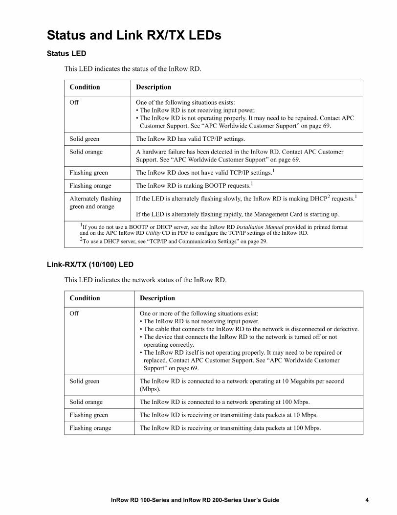
This LED indicates the status of the InRow RD.
Link-RX/TX (10/100) LED
This LED indicates the network status of the InRow RD.
Condition Description
Off One of the following situations exists:• The InRow RD is not receiving input power.• The InRow RD is not operating properly. It may need to be repaired. Contact APC
Customer Support. See “APC Worldwide Customer Support” on page 69.
Solid green The InRow RD has valid TCP/IP settings.
Solid orange A hardware failure has been detected in the InRow RD. Contact APC Customer Support. See “APC Worldwide Customer Support” on page 69.
Flashing green The InRow RD does not have valid TCP/IP settings.1
Flashing orange The InRow RD is making BOOTP requests.1
Alternately flashing green and orange
If the LED is alternately flashing slowly, the InRow RD is making DHCP2 requests.1
If the LED is alternately flashing rapidly, the Management Card is starting up.1If you do not use a BOOTP or DHCP server, see the InRow RD Installation Manual provided in printed formatand on the APC InRow RD Utility CD in PDF to configure the TCP/IP settings of the InRow RD. 2To use a DHCP server, see “TCP/IP and Communication Settings” on page 29.
Condition Description
Off One or more of the following situations exist:• The InRow RD is not receiving input power.• The cable that connects the InRow RD to the network is disconnected or defective.• The device that connects the InRow RD to the network is turned off or not
operating correctly.• The InRow RD itself is not operating properly. It may need to be repaired or
replaced. Contact APC Customer Support. See “APC Worldwide Customer Support” on page 69.
Solid green The InRow RD is connected to a network operating at 10 Megabits per second (Mbps).
Solid orange The InRow RD is connected to a network operating at 100 Mbps.
Flashing green The InRow RD is receiving or transmitting data packets at 10 Mbps.
Flashing orange The InRow RD is receiving or transmitting data packets at 100 Mbps.
4InRow RD 100-Series and InRow RD 200-Series User’s Guide

Watchdog FeaturesOverview
To detect internal problems and recover from unanticipated inputs, the InRow RD uses internal, system-wide watchdog mechanisms. When it restarts to recover from an internal problem, a System: Warmstart event is recorded in the event log.
Network interface watchdog mechanism
The InRow RD implements internal watchdog mechanisms to protect itself from becoming inaccessible over the network. For example, if the InRow RD does not receive any network traffic for 9.5 minutes (either direct traffic, such as SNMP, or broadcast traffic, such as an Address Resolution Protocol [ARP] request), it assumes that there is a problem with its network interface and restarts.
Resetting the network timer
To ensure that the InRow RD does not restart if the network is quiet for 9.5 minutes, the InRow RD attempts to contact the default gateway every 4.5 minutes. If the gateway is present, it responds to the InRow RD, and that response restarts the 9.5-minute timer. If your application does not require or have a gateway, specify the IP address of a computer that is running on the network most of the time and is on the same subnet. The network traffic of that computer will restart the 9.5-minute timer frequently enough to prevent the InRow RD from restarting.
InRow RD 100-Series and InRow RD 200-Series User’s Guide5

Control Console
How To Log OnOverview
You can use either a local (serial) connection, or a remote (Telnet or SSH) connection with a computer on the same network (LAN) as the InRow RD to access the control console.
Use case-sensitive user name and password entries to log on (by default, apc and apc for an Administrator, or device and apc for a Device User). A Read-Only User has no access to the control console.
If you cannot remember your user name or password, see “How to Recover from a Lost Password” on page 3.
Remote access to the control console
You can access the control console through Telnet or Secure SHell (SSH). Telnet is enabled by default. Enabling SSH disables Telnet.
To enable or disable these access methods:
• In the Web interface, on the Administration tab, select Network on the top menu bar, and then the access option under Console on the left navigation menu.
• In the control console, use the Telnet/SSH option of the Network menu.Telnet for basic access. Telnet provides the basic security of authentication by user name and password, but not the high-security benefits of encryption.
To use Telnet to access the control console:
1. From a computer on the same network as the InRow RD, at a command prompt, type telnet and the System IP address for the InRow RD (for example, telnet 139.225.6.133, when the InRow RD uses the default Telnet port of 23), and press ENTER.
If the InRow RD uses a non-default port number (from 5000 to 32768), you must include a colon or a space, depending on your Telnet client, between the IP address (or DNS name) and the port number.
2. Enter the user name and password (by default, apc and apc for an Administrator, or device and apc for a Device User).
SSH for high-security access. If you use the high security of SSL for the Web interface, use Secure SHell (SSH) for access to the control console. SSH encrypts user names, passwords and transmitted data. The interface, user accounts, and user access rights are the same whether you access the control console through SSH or Telnet, but to use SSH, you must first configure SSH and have an SSH client program installed on your computer.
6InRow RD 100-Series and InRow RD 200-Series User’s Guide

Local access to the control console
For local access, use a computer that connects to the InRow RD or other device through the serial port, to access the control console:
1. Select a serial port at the computer and disable any service that uses the port.2. Connect the provided serial cable from the selected port on the computer to the configuration port
at the InRow RD.3. Run a terminal program (e.g., HyperTerminal), and configure the selected port for 9600 bps, 8
data bits, no parity, 1 stop bit, and no flow control.4. Press ENTER, and at the prompts, enter your user name and password.
Main ScreenSample main screen
Following is an example of the screen displayed when you log on to the control console at the InRow RD.
Information and status fields
Main screen information fields.
• Two fields identify the APC operating system (AOS) and application (APP) firmware versions.
Network Management Card AOS vx.x.xInRow RD APP vx.x.x
• Three fields identify the system name, contact person, and location of the InRow RD. (In the control console, use the System menu to set these values.)
Name: Test Lab
Contact: Don Adams
Location: Building 3
American Power Conversion Network Management Card AOS vx.x.x (c)Copyright 2009 All Rights Reserved InRow RD APP vx.x.x--------------------------------------------------------------------------
Name : Test Lab Date : 11/30/2009 Contact : Don Adams Time : 5:58:30 Location : Building 3 User : Administrator Up Time : 0 Days, 21 Hours, 21 Minutes Stat : P+ N+ A+
------- Control Console --------------------------------------------------
1- Device Manager 2- Network 3- System 4- Logout <ESC>- Main Menu, <ENTER>- Refresh, <CTRL-L>- Event Log
InRow RD 100-Series and InRow RD 200-Series User’s Guide7

• The Up Time field reports how long the InRow RD has been running since it was last turned on or reset.
Up Time: 0 Days 21 Hours 21 Minutes
• Two fields report when you logged in, by date and time.
Date : 11/30/2009
Time : 5:58:30
• The User field reports whether you logged in through the Administrator or Device User account. (The Read Only User account cannot access the Control Console.)
User : Administrator
Main screen status fields.
• The Stat field reports the InRow RD status.
Stat : P+ N+ A+
If P+ is not displayed, contact APC support staff. See “APC Worldwide Customer Support” on page 69.
P+ The APC operating system (AOS) is functioning properly.
N+ The network is functioning properly.
N? A BOOTP request cycle is in progress.
N– The InRow RD failed to connect to the network.
N! Another device is using the IP address of this InRow RD.
A+ The application is functioning properly.
A– The application has a bad checksum.
A? The application is initializing.
A! The application is not compatible with the AOS.
8InRow RD 100-Series and InRow RD 200-Series User’s Guide
Control Console MenusOverview
The control console provides options to monitor and configure the InRow RD.
How to use control console menus
The menus in the control console list options by number and name. To use an option, type the option’s number, press ENTER, and follow any on-screen instructions. If you use an option that changes a setting or value, select Accept Changes to save your change before you exit the menu.
While using a menu, you can also do the following:
• Type ? and press ENTER for menu option descriptions if help exists for the menu• Press ENTER to refresh the menu• Press ESC to go back to the menu from which you accessed the current menu• Press CTRL+C to return to the main (Control Console) menu• Press CTRL+D to toggle between menus• Press CTRL+L to access the event log
Control console structureFor menus not specific to the InRow RD but shared among APC network-enabled devices, names and locations of options differ from those of the Web interface. The menu structure in the control console is retained from earlier firmware versions for compatibility with scripts and programs that rely on that structure.
Main menu
Use the main Control Console menu to access the control console’s management features:
1- Device Manager
2- Network
3- System
4- Logout
Note: When you log on as Device Manager (equivalent to Device User in the Web interface), you can access only the Device Manager menus and the Logout menu.
Device Manager menu
An Administrator or Device User can use the options of the Device Manager menu to configure InRow RD parameters and display detailed status.
InRow RD 100-Series and InRow RD 200-Series User’s Guide9
Network menu
To perform these tasks, use the options of the Network menu:
• Configure the TCP/IP settings of the InRow RD or, if the InRow RD obtains its TCP/IP settings from a server, configure the settings for the type of server (DHCP or BOOTP).
• Use the Ping utility.• Define settings that affect FTP, Telnet and SSH, the Web interface and SSL, SNMP, e-mail, DNS,
and Syslog.
System menu
To perform these tasks, use the options of the System menu:
• Control Administrator and Device Manager access. (You can control Read Only User access by using the Web interface only.)
• Define the Name, Contact, and Location values for the system.• Set the date and time used by the InRow RD.• Through the Tools option:
– Restart the InRow RD interface.– Reset parameters to their default values.– Delete SSH host keys and SSL certificates.– Upload an initialization file (.ini file) that has been downloaded from another InRow RD. The
current InRow RD then uses the values in that .ini file to configure its own settings.• Access system information about the InRow RD.
10InRow RD 100-Series and InRow RD 200-Series User’s Guide
Web Interface
IntroductionOverview
The Web interface provides options to manage the InRow RD.
See “Web” on page 34 for information on how to select, enable, and disable the protocols that control access to the Web interface and to define the Web-server ports for the protocols.
Supported Web browsersYou can use Microsoft® Internet Explorer (IE) 5.5 and higher (on Windows operating systems only) or Mozilla Firefox 1.x or higher (on all operating systems) to access the InRow RD through its Web interface. Other commonly available browsers may work but have not been fully tested by APC.
The InRow RD cannot work with a proxy server. Therefore, before you can use a Web browser to access its Web interface, you must do one of the following:
• Configure the Web browser to disable the use of a proxy server for the InRow RD.• Configure the proxy server so that it does not proxy the specific IP address of the InRow RD.
How to Log OnOverview
You can use the DNS name or System IP address of the InRow RD for the URL address of the Web interface. Use your case-sensitive user name and password to log on. The default user name differs by account type:
• apc for an Administrator• device for a Device User• readonly for a Read-Only User
The default password is apc for all three account types.
Note: If you are using HTTPS (SSL/TSL) as your access protocol, your logon credentials are compared with information in a server certificate. If the certificate was created with the APC Security Wizard, and an IP address was specified as the common name in the certificate, you must use an IP address to log on to the InRow RD. If a DNS name was specified as the common name on the certificate, you must use a DNS name to log on.
For information about the Web page that displays when you log on, see “Home Page” on page 13.
InRow RD 100-Series and InRow RD 200-Series User’s Guide11

URL address formats
Type the DNS name or IP address of the InRow RD in the URL address field of the Web browser and press ENTER. When you specify a non-default Web server port in Internet Explorer, you must include http:// or https:// in the URL.
Common browser error messages at log-on.
URL format examples.
• For a DNS name of Web1:– http://Web1 if HTTP is your access mode– https://Web1 if HTTPS (HTTP with SSL) is your access mode
• For a System IP address of 139.225.6.133 and the default Web server port (80):– http://139.225.6.133 if HTTP is your access mode– https://139.225.6.133 if HTTPS (HTTP with SSL) is your access mode
• For a System IP address of 139.225.6.133 and a non-default Web server port (5000): – http://139.225.6.133:5000 if HTTP is your access mode– https://139.225.6.133:5000 if HTTPS (HTTP with SSL) is your access mode.
Error Message Browser Cause of the Error
“You are not authorized to view this page” or “Someone is currently logged in...”
Internet Explorer, Firefox
Someone else is logged on
“This page cannot be displayed.” Internet Explorer Web access is disabled, or the URL was not correct
“Unable to connect.” Firefox
12InRow RD 100-Series and InRow RD 200-Series User’s Guide

Home PageOverview
On the Overview page of the Home tab, displayed when you log on to the Web interface, you can view active alarm conditions and the most recent events recorded in the event log.
Quick status icons. At the upper right corner of every page, one or more icons and accompanying text indicate the current operating status of the InRow RD and the number of active alarms of that severity:
Active Alarms. The Active Alarms section of the Overview page summarizes the status of the InRow RD:
• The Online icon displays if no alarms exist. • One or both of the other icons (Critical and Warning) display if any alarms exist, and after each
icon, the number of active alarms of that severity.To return to the Home page to view its summary of InRow RD status, including the active alarms, click a quick status icon on any page of the interface.
Group. The Group section lists the cooling output provided by the group, the target temperatures for air entering and leaving the InRow RD, and the highest and lowest recorded temperatures of air entering and leaving the InRow RDs in the group. Click More Status to view additional overview information about the group.
Unit. The Unit section displays the name and location of the cooling unit, and lists its operating mode, the cooling output it is providing, and the temperature of air entering the unit enclosure. Click More Status to view additional overview information about the unit.
Recent Device Events. The Recent Device Events section displays, in reverse chronological order, the events that occurred most recently and the dates and times they occurred. Click More Events to view the entire event log.
Alarm Status
From the Home tab, click Alarm Status on the top menu bar to view the severity and description of each active alarm or to clear all of the active group and unit alarms.
Icon Description
Critical: A critical alarm exists, which requires immediate action.
Warning: An alarm condition requires attention and could jeopardize your data or equipment if its cause is not addressed.
Online: No alarms are present, and the InRow RD is operating normally.
InRow RD 100-Series and InRow RD 200-Series User’s Guide13
How to Use the Tabs, Menus, and LinksTabs
In addition to the tab for the Home page, the following tabs are displayed. Click a tab to display a set of menu options:
• Group: View the status of all InRow RDs in the group. View active alarms and recent events. Configure thresholds and other parameters related to the group.
• Unit: Display InRow RD status, configure InRow RD parameters, configure and schedule maintenance, and view information about the InRow RD.
• Logs: View and configure event and data logs.• Administration: Configure security, network connection, notification, and general settings.
Menus
Left navigation menu. Each tab (except the tab for the home page) has a left navigation menu, consisting of headings and options:
• If a heading has indented option names below it, the heading itself is not a navigational link. Click an option to display or configure parameters.
• If a heading has no indented option names, the heading itself is the navigational link. Click the heading to display or configure parameters.
Top menu bar. The Administration tab has a selection of menu options on the top menu bar. Select one of the menu options to display its left navigation menu.
Quick Links
At the lower left on each page of the interface, there are three configurable links. By default, the links access the URLs for these Web pages:
• Link 1: The home page of the APC Web site.• Link 2: Demonstrations of APC Web-enabled products.• Link 3: Information on APC Remote Monitoring Services.
To reconfigure the links, see “Configuring Links” on page 50.
14InRow RD 100-Series and InRow RD 200-Series User’s Guide
Group and Unit Configuration
Viewing and Configuring Group SettingsOverview page
The Overview page, which displays by default the first time you select the Group tab, provides basic group status information.
• Cool Setpoint—The target value for the air temperature. A Cool setpoint equal or above the Supply Air Setpoint indicates that the group is operating normally. The Cool Setpoint should be set a few degrees above the Supply Air Setpoint when operating in the InRow mode.
• Supply Air Setpoint—The target value for air leaving the cooling units in the group. The Supply Air Setpoint should be set a few degrees below the Cool Setpoint to ensure that the group is operating normally.
• Air Flow—The amount of air flow provided by the group.• Maximum Return Air Temperature—The highest return temperature recorded in the group.• Minimum Return Air Temperature—The lowest return temperature recorded in the group.• Cool Output—The actual cooling output of the group.• Cool Demand—The amount of cooling the group requires from the units to maintain the Cool
Setpoint.
Setpoints page
Use the Setpoints page to configure the temperature setpoints, capacity control mode, and fan speed mode for the cooling group.
• Cool Setpoint—The target value for the air temperature. The Cool Setpoint value must be equal to or greater than the Supply Air Setpoint value.
• Cool Deadband—The hysteresis value that prevents the unit from turning on and turning off too rapidly. For a cooling unit to activate its compressor, the air temperature must exceed the Cool Setpoint plus the Cool Deadband.
• Supply Air Setpoint—The target value for air leaving the cooling units in the group. The Supply Air Setpoint value must be equal to or below the Cool Setpoint value.
• Capacity Control—The method the units will use to regulate the cooling demand. Discrete is used for the Spot Cooling configuration mode only. Use Proportional for all othe configuration modes.
– Proportional Mode—The unit modulates the fan speeds and Hot Gas Bypass Valve (HGBV) to match the cooling output to the load demand, so the compressor turns off less frequently.
– Discrete Mode—The unit runs the fans at a set speed with the HGBV fully closed. The unit activates the compressor when the Return Air Temperature reaches the Cool Setpoint plus the Cool Deadband. The unit deactivates the compressor when the Return Air Temperature reaches the Cool Setpoint.
InRow RD 100-Series and InRow RD 200-Series User’s Guide15
• Fan Speed Preference — The preferred fan speed for normal operation of the cooling unit. Selecting the RACS or HACS mode sets the desired temperature difference between the rack inlet air temperature and the rack outlet air temperature.
• Fan Speed Control (Spot Proportional, In-Row, RACS or HACS cooling modes)—The method the units will use to control fan speed, Automatic or Manual.
– Automatic—The unit controls the evaporator fan speed based on cooling demand. – Manual—The evaporator fan speed is fixed at a constant speed. Use the Fan Speed
Preference setting to define the default speed.
Configuration page
Use the settings on the Configuration page to define how the units will divide the cooling load:
• Number of Units in Group—Specify the number of units in the group. Valid values are 1–12. Note: If you only have one air conditioner, select 1 from the Number of Units in Group drop-down list and define the group settings.
• Number of Backup Units—Specify the number of backup units in the group. Valid values are 0–11.
• Run-Time Balancing Enable—Enable this option (the default setting) to balance the unit run time across the units in the group and to ensure that all units have consistent operating time. Disable this option if the unit is using the Spot Cooling mode.
• Load Assist Enable—Define whether the backup units will assist the primary units when the cooling demand exceeds the cooling output capacity of the primary units.
• Configuration Type—The air flow control strategy the Group uses. You can change this setting only when all of the units in the group are in Standby mode.
– Spot—The unit regulates the Return Air Temperature. The Rack Inlet Air Temperature sensor is ignored for control purposes. Use this option for standalone units only.
– Rack Air Containment System (RACS)—Air flow in the enclosure is controlled by a ducting system fitted to the enclosure.
– Hot Aisle Containment System (HACS)—Air flow in the room is controlled by enclosing the hot air aisle.
– In-Row—Air flow is horizontal to allow in-row operation of cooling solutions. (Backup and Load Assist functions are disabled in InRow mode.)
Only an APC Field Service Engineer may change these values:
• Cool Gain “P”—Set the proportional multiplier to correct for differences between the selected control sensor's actual temperature and the setpoint.
• Cool Reset Rate “I”—Set the integral multiplier to correct for the proportional offset.• Cool Derivative “D”—Set the derivative multiplier to counteract overshoot and droop during
changes in the room load.
Units page
View a list of units in the group. For each unit, view its location, unit-type, application firmware version, and IP address.
To ensure optimal group performance, confirm that the units use the same application firmware version.
16InRow RD 100-Series and InRow RD 200-Series User’s Guide

The value InRow RD should always display in the unit-type field. You can group InRow RD 100-series and InRow RD 200-series units, but do not attempt to connect other cooling-unit models to the group. Doing so may cause communication problems and prevent the group from operating correctly.
To configure the name and location of a unit, see “Identification” on page 18.
Viewing and Configuring Unit SettingsStatus > Overview page
The Overview page, which displays by default the first time you select the Unit tab, provides basic unit status information.
• Operating Mode—The current operating mode of the unit:– On—The unit is providing cooling.– Standby—The user turned off the cooling functions of the unit, or the input contact is in an
abnormal state.– Idle—The unit is not providing cooling because it has active alarms.– Refrig—The unit is in Refrigerant Fill mode.
• Compressor State—The present operating status (on or off) of the compressor for this unit.• Cool Output—The amount of cooling provided by the unit.• Cool Demand—The amount of cooling that is currently required.• Rack Inlet Temperature—The temperature of air entering the enclosure.• Supply Air Temperature—The temperature of air leaving the unit.• Return Air Temperature—The temperature of air entering the unit.• Suction Temperature—The temperature of the low pressure (suction) refrigerant line.• Air Flow—The amount of air that must flow through the evaporator to maintain the setpoint
temperature.• Fan Speed—The speed of the fans that regulate air flow through the evaporator.• Fluid Valve Position (ACRD100)—The position of the valve that regulates fluid flow through
the unit (0% indicates that the valve is fully closed and 100% indicates that it is fully opened).• Hot Gas Bypass Valve Position (ACRD200)—The position of the valve that regulates hot gas
bypass (0% indicates that the valve is fully closed and 100% indicates that it is fully opened).
InRow RD 100-Series and InRow RD 200-Series User’s Guide17
Status > Detailed Status page
• Input State—The current state of the input contact. If the input contact is in an abnormal state, an alarm occurs and the unit changes its operating mode to Standby.
• Output State—The current state of the output relay. An alarm will cause the output relay to change from its normal state.
• OHE Input State—The current state of the Outside Heat Exchanger (OHE) input. An alarm is generated if the current state differs from the configured normal state.
• OHE Output State—The current state of the OHE output. • Filter Differential Pressure—The difference in pressure on either side of the air filters. A high
differential pressure could indicate a clogged filter.• Suction Pressure—The pressure of the low pressure (suction) refrigerant line.• Discharge Pressure—The pressure of the high pressure (discharge) refrigerant line.• Superheat Temperature—The difference between the suction temperature and the evaporator
dew point temperature.
Identification page
Factory Information. This information is useful to APC Customer Support in helping to troubleshoot any problems you may be having with this unit.
• Model Number—The model number of the unit. • Serial Number—The serial number of the unit.• Controller Firmware—The version of the controller firmware.• Hardware Revision—The version of the hardware.• Date of Manufacture—The date on which the manufacture of this device was completed.
Identification. This information identifies the unit on the Overview page of the Home tab.
• Name—The name to assign to the unit. • Location—The physical location of the unit.
Run Hours page
View the number of hours the unit and its components have been in operation. The air filter, fans, condensate pump, compressor, and upper and lower fan power supplies require routine maintenance. After you perform maintenance on a component, select its Reset check box and click Apply to reset the run-hours to zero (0).
For information about routine maintenance, see the Operation Manual for your unit, provided on the Utility CD or the APC Web site, www.apc.com.
Service Intervals page
Define the number of weeks after which an air filter must be cleaned or replaced (18 weeks, by default). By default, the unit generates an alarm when the interval expires. To disable the alarm, clear the Alarm check box and click Apply.
18InRow RD 100-Series and InRow RD 200-Series User’s Guide

Thresholds page
Sensor Values. View the temperature values reported by these sensors:
• Rack Inlet Temperature—The temperature of air entering the enclosure on which the Rack Inlet Temperature Sensor is installed.
• Supply Air Temperature—The temperature of air leaving the unit.• Return Air Temperature—The temperature of air entering the unit.
Thresholds. Configure the temperature thresholds:
• Rack Inlet High Temperature—Specify the high-temperature threshold. If air entering the enclosure is above this temperature, the unit generates an alarm.
• Supply Air High Temperature—Specify the high temperature threshold for air leaving the unit. If the temperature exceeds this threshold, the unit generates an alarm.
• Return Air High Temperature—Specify the high temperature threshold for air entering the unit. If the temperature exceeds this threshold, the unit generates an alarm.
Configuration page
Configure the startup delay, define the normal state of input contacts and output relays that affect the behavior of the unit, define how the unit will respond when an alarm condition is detected, and specify the units of measure the unit will use.
• Startup Delay—Set the delay that begins when power is applied and ends when the unit starts. Valid values are 0 to 999 seconds.
• Idle on Leak Detect—Idle the unit when a leak is detected. By default, this feature is not activated.
• Input Normal State—Define the normal state of the input, open or closed. The unit changes its operating mode to Standby when the input is not in its normal state.
• Output Normal State—Define the normal state of the output, open or closed. When one or more alarms are present on the output source, the output will be set to its abnormal state.
• Output Source—Define the type of alarm that will change the state of the output.• OHE Input Normal State—Define the normal state of the Outside Heat Exchanger (OHE), open
or closed. An alarm is generated if the current state differs from the configured normal state.• Unit Role Override—When set to Automatic (the default setting), the system defines whether
this unit is used as a primary or redundant unit. When set to Forced On, the unit is always a primary unit.
• Idle on Cool Fail—Idle the unit when the supply temperature exceeds 90°F (32.2°C) for a maximum of five minutes. The time limit decreases as the temperature rises. By default, this feature is enabled.
• Display Units—Define whether this interface will display Metric or US units of measure
InRow RD 100-Series and InRow RD 200-Series User’s Guide19

Logs
Use the Event and Data LogsEvent log
Path: Logs > Events > options
You can view, filter, or delete the event log. By default, the log displays all events recorded during the last two days, in reverse chronological order.
For lists of all configurable events and their current configuration, select the Administration tab, Notification on the top menu bar, and by event under Event Actions on the left navigation menu.
See “Configuring by event” on page 42.
To display the event log (Logs > Events > log):
• By default, view the event log as a page of the Web interface. The most recent event is recorded on page 1. In the navigation bar below the log:
– Click a page number to open a specific page of the log. – Click Previous or Next to view the events recorded immediately before or after the events
listed on the open page. – Click << to return to the first page or click >> to view the last page of the log.
• To see the listed events on one page, click Launch Log in New Window from the event log page to display a full-screen view of the log.
Note: In your browser's options, JavaScript® must be enabled for you to use the Launch Log in New Window button. You can also use FTP or SCP to view the event log. See “How to use FTP or SCP to retrieve log files” on page 23.
To filter the log (Logs > Events > log):
• Filtering the log by date or time: To display the entire event log, or to change the number of days or weeks for which the log displays the most recent events, select Last. Select a time range from the drop-down menu, then click Apply. The filter configuration is saved until the InRow RD restarts.
To display events logged during a specific time range, select From. Specify the beginning and ending times (using the 24-hour clock format) and dates for which to display events, then click Apply. The filter configuration is saved until the InRow RD restarts.
• Filtering the log by event: To specify the events that display in the log, click Filter Log. Clear the checkbox of an event category or alarm severity level to remove it from view. Text at the upper right corner of the event log page indicates that a filter is active. As Administrator, click Save As Default to save this filter as the default log view for all users. If you do not click Save As Default, the filter is active until you clear it or until the InRow RD restarts. To remove an active filter, click Filter Log, then Clear Filter (Show All).
20InRow RD 100-Series and InRow RD 200-Series User’s Guide
Note: Events are processed through the filter using OR logic.
• Events that you do not select from the Filter By Severity list never display in the filtered event log, even if the event occurs in a category you selected from the Filter by Category list.
• Events that you do not select from the Filter by Category list never display in the filtered event log, even if devices in the category enter an alarm state you selected from the Filter by Severity list.
To delete the log (Logs > Events > log):
To delete all events recorded in the log, click Clear Log on the Web page that displays the log. Deleted events cannot be retrieved.
To disable the logging of events based on their assigned severity level or their event category, see “Configuring by group” on page 42.
To configure reverse lookup (Logs > Events > reverse lookup):
Reverse lookup is disabled by default. Enable this feature unless you have no DNS server configured or have poor network performance because of heavy network traffic.
With reverse lookup enabled, when a network-related event occurs, both the IP address and the domain name for the networked device associated with the event are logged in the event log. If no domain name entry exists for the device, only its IP address is logged with the event. Since domain names generally change less frequently than IP addresses, enabling reverse lookup can improve the ability to identify addresses of networked devices that are causing events.
Data log
Path: Logs > Data > options
View a log of measurements about the InRow RD. Each entry is listed by the date and time the data was recorded.
To display the data log (Logs > Data > log):
• By default, view the data log as a page of the Web interface. • To see the listed data on one page, click Launch Log in New Window from the data log page to
display a full-screen view of the log.Note: In your browser's options, JavaScript® must be enabled for you to use the Launch Log in New Window button. You can also use FTP or SCP to view the event log. See “How to use FTP or SCP to retrieve log files” on page 23.
InRow RD 100-Series and InRow RD 200-Series User’s Guide21

To filter the log by date or time (Logs > Data > log):
To display the entire data log, or to change the number of days or weeks for which the log displays the most recent events, select Last. Select a time range from the drop-down menu, then click Apply. The filter configuration is saved until the device restarts.
To display data logged during a specific time range, select From. Specify the beginning and ending times (using the 24-hour clock format) and dates for which to display data, then click Apply. The filter configuration is saved until the device restarts.
To delete the data log:
To delete all data recorded in the log, click Clear Data Log on the Web page that displays the log. Deleted data cannot be retrieved.
To set the data collection to graphing (Logs > Data > graphing):
Use this option to create an interactive data graph. Select a maximum of four data parameters from the Graph Data pull down menu. Choose a time frame from the Graph Time pull down menu or enter a date range in the From and To fields. Click Apply to generate the graph.
Click Launch Graph in New Window to launch the graph in a new browser window that provides a full-screen view.
Use the zoom tool above the graph to magnify the data shown on the screen. You can also click on any point in the graph to center and magnify that point on the screen. Use the left or right arrows above the graph to navigate through the data displayed in the magnified graph. Hover over any horizontal line in the graph to view the date, time and Y-axis value for that data record.
To set the data collection interval (Logs > Data > interval):
Define, in the Log Interval setting, how frequently data is sampled and stored in the data log, and view the calculation of how many days of data the log can store, based on the interval you selected. When the log is full, the older entries are deleted. To avoid automatic deletion of older data, enable and configure data log rotation, described in the next section.
To configure data log rotation (Logs > Data > rotation):
Set up a password-protected data log repository on a specified FTP server. Enabling rotation causes the contents of the data log to be appended to the file you specify by name and location. Updates to this file occur at the upload interval you specify.
Parameter Description
Data Log Rotation Enable or disable (the default) data log rotation.
FTP Server Address The location of the FTP server where the data repository file is stored.
User Name The user name required to send data to the repository file. This User Name must also be configured to have read and write access to the data repository file and the directory (folder) in which it is stored.
Password The password required to send data to the repository file.
File Path The path to the repository file.
22InRow RD 100-Series and InRow RD 200-Series User’s Guide
How to use FTP or SCP to retrieve log files
An Administrator or Device User can use FTP or SCP to retrieve a tab-delineated event log file (event.txt) or data log file (data.txt) and import it into a spreadsheet.
• The file reports all events or data recorded since the log was last deleted or (for the data log) truncated because it reached maximum size.
• The file includes information that the event log or data log does not display.– The version of the file format (first field)– The date and time the file was retrieved– The Name, Contact, and Location values and IP address of the InRow RD– The unique Event Code for each recorded event (event.txt file only)
Note: The InRow RD uses a four-digit year for log entries. You may need to select a four-digit date format in your spreadsheet application to display all four digits.
If you are using the encryption-based security protocols for your system, use Secure CoPy (SCP) to retrieve the log file.
If you are using unencrypted authentication methods for the security of your system, use FTP to retrieve the log file.
See the Security Handbook, available on the Utility CD provided with your InRow RD or on the APC Web site (www.apc.com), for information on available protocols and methods for setting up the type of security you need.
Filename The name of the repository file (an ASCII text file).
Delay X hours between uploads. The number of hours between uploads of data to the file.
Upload every X minutes The number of minutes between attempts to upload data to the file after an upload failure.
Up to X times The maximum number of times the upload will be attempted after an initial failure.
Until Upload Succeeds Attempt to upload the file until the transfer is completed.
Parameter Description
InRow RD 100-Series and InRow RD 200-Series User’s Guide23

To use SCP to retrieve the files. To use SCP to retrieve the event.txt file, use the following command:
scp username@hostname_or_ip_address:event.txt ./event.txt
To use SCP to retrieve the data.txt file, use the following command:
scp username@hostname_or_ip_address:data.txt ./data.txt
To use FTP to retrieve the files. To use FTP to retrieve the event.txt or data.txt file:
1. At a command prompt, type ftp and the IP address of the InRow RD, and press ENTER.
If the Port setting for the FTP Server option (set through the Network menu of the Administration tab) has been changed from its default (21), you must use the non-default value in the FTP command. For Windows FTP clients, use the following command, including spaces. (For some FTP clients, you must use a colon instead of a space between the IP address and the port number.)
ftp>open ip_address port_number
To set a non-default port value to enhance security for the FTP Server, see “FTP Server” on page 40. You can specify any port from 5001 to 32768.
2. Use the case-sensitive User Name and Password for Administrator or Device User to log on. For Administrator, apc is the default for User Name and Password. For the Device User, the defaults are device for User Name and apc for Password.
3. Use the get command to transmit the text of a log to your local drive.
ftp>get event.txt
or
ftp>get data.txt
4. You can use the del command to clear the contents of either log.
ftp>del event.txt
or
ftp>del data.txt
You will not be asked to confirm the deletion.
• If you clear the data log, the event log records a deleted-log event.
• If you clear the event log, a new event.txt file records the event.
5. Type quit at the ftp> prompt to exit from FTP.
24InRow RD 100-Series and InRow RD 200-Series User’s Guide
Administration: Security
Local UsersSetting user access
Path: Administration > Security > Local Users > options
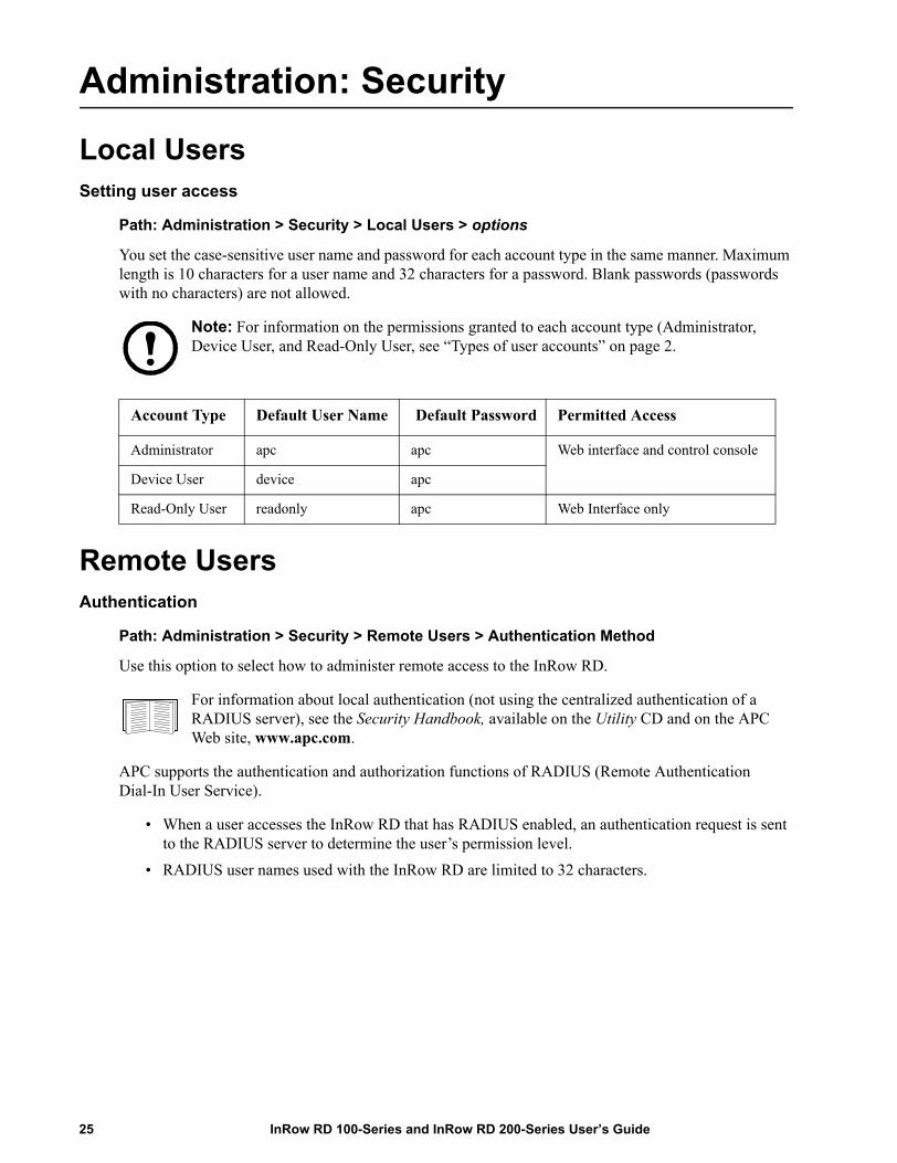
You set the case-sensitive user name and password for each account type in the same manner. Maximum length is 10 characters for a user name and 32 characters for a password. Blank passwords (passwords with no characters) are not allowed.
Note: For information on the permissions granted to each account type (Administrator, Device User, and Read-Only User, see “Types of user accounts” on page 2.
Remote UsersAuthentication
Path: Administration > Security > Remote Users > Authentication Method
Use this option to select how to administer remote access to the InRow RD.
For information about local authentication (not using the centralized authentication of a RADIUS server), see the Security Handbook, available on the Utility CD and on the APC Web site, www.apc.com.
APC supports the authentication and authorization functions of RADIUS (Remote Authentication Dial-In User Service).
• When a user accesses the InRow RD that has RADIUS enabled, an authentication request is sent to the RADIUS server to determine the user’s permission level.
• RADIUS user names used with the InRow RD are limited to 32 characters.
Account Type Default User Name Default Password Permitted Access
Administrator apc apc Web interface and control console
Device User device apc
Read-Only User readonly apc Web Interface only
InRow RD 100-Series and InRow RD 200-Series User’s Guide25

Select one of the following:
• Local Authentication Only: RADIUS is disabled. Local authentication is enabled.• RADIUS, then Local Authentication: RADIUS and local authentication are enabled.
Authentication is requested from the RADIUS server first. If the RADIUS server fails to respond, local authentication is used.
• RADIUS Only: RADIUS is enabled. Local authentication is disabled.Note: If RADIUS Only is selected, and the RADIUS server is unavailable, improperly identified, or improperly configured, you must use a serial connection to the control console and change the Access setting to Local Authentication Only or RADIUS, then Local Authentication to regain access.
RADIUS
Path: Administration > Security > Remote Users > RADIUS
Use this option to do the following:
• List the RADIUS servers (a maximum of two) available to the InRow RD and the time-out period for each.
• Click Add Server, and configure the parameters for authentication by a new RADIUS server:• Click a listed RADIUS server to display and modify its parameters.
RADIUS Setting Definition
RADIUS Server The server name or IP address of the RADIUS server.
Note: RADIUS servers use port 1812 by default to authenticate users. To use a different port, add a colon followed by the new port number to the end of the RADIUS server name or IP address.
Secret The shared secret between the RADIUS server and the InRow RD.
Timeout The time in seconds that the InRow RD waits for a response from the RADIUS server.
Test Settings Enter the Administrator user name and password to test the RADIUS server path that you have configured.
Skip Test and Apply Do not test the RADIUS server path.
Switch Server Priority Change which RADIUS server will authenticate users if two configured servers are listed and RADIUS, then Local Authentication or RADIUS Only is the enabled authentication method.
26InRow RD 100-Series and InRow RD 200-Series User’s Guide
Configuring the RADIUS ServerSummary of the configuration procedure
You must configure your RADIUS server to work with the InRow RD.
For examples of the RADIUS users file with Vendor Specific Attributes (VSAs) and an example of an entry in the dictionary file on the RADIUS server, see the APC Security Handbook.
1. Add the IP address of the InRow RD to the RADIUS server client list (file).2. Users must be configured with Service-Type attributes unless Vendor Specific Attributes (VSAs)
are defined. If no Service-Type attributes are configured, users will have read-only access (on the Web interface only).
See your RADIUS server documentation for information about the RADIUS users file, and see the APC Security Handbook for an example.
3. Vendor Specific Attributes (VSAs) can be used instead of the Service-Type attributes provided by the RADIUS server. VSAs requires a dictionary entry and a RADIUS users file. In the dictionary file, define the names for the ATTRIBUTE and VALUE keywords, but not for the numeric values. If you change numeric values, RADIUS authentication and authorization will fail. VSAs take precedence over standard RADIUS attributes.
Configuring a RADIUS server on UNIX® with shadow passwords
If UNIX shadow password files are used (/etc/passwd) with the RADIUS dictionary files, the following two methods can be used to authenticate users:
• If all UNIX users have administrative privileges, add the following to the RADIUS “user” file. To allow only Device Users, change the APC-Service-Type to Device.
DEFAULT Auth-Type = System APC-Service-Type = Admin
• Add user names and attributes to the RADIUS “user” file, and verify password against /etc/passwd. The following example is for users bconners and thawk:
bconners Auth-Type = System APC-Service-Type = Admin
thawk Auth-Type = System APC-Service-Type = Device
Supported RADIUS servers
APC supports FreeRADIUS and Microsoft IAS 2003. Other commonly available RADIUS applications may work but have not been fully tested by APC.
InRow RD 100-Series and InRow RD 200-Series User’s Guide27

Inactivity Timeout Path: Administration > Security > Auto Log Off
Use this option to configure the time (3 minutes by default) that the system waits before logging off an inactive user. If you change this value, you must log off for the change to take effect.
Note: This timer continues to run if a user closes the browser window without first logging off by clicking Log Off at the upper right. Because that user is still considered to be logged on, no user of that account type can log on until the time specified as Minutes of Inactivity expires. For example, with the default value for Minutes of Inactivity, if a Device User closes the browser window without logging off, no Device User can log on for 3 minutes.
28InRow RD 100-Series and InRow RD 200-Series User’s Guide
Administration: Network Features
TCP/IP and Communication SettingsTCP/IP settings
Path: Administration > Network > TCP/IP
The TCP/IP option on the side menu bar, selected by default when you choose Network on the top menu bar, displays the current IP address, subnet mask, default gateway, and MAC address of the InRow RD.
On the same page, TCP/IP Configuration provides the following options for how the TCP/IP settings will be configured when the InRow RD turns on, resets, or restarts: Manual, BOOTP, DHCP, and DHCP & BOOTP.
For information on DHCP and DHCP options, see RFC2131 and RFC2132.
InRow RD 100-Series and InRow RD 200-Series User’s Guide29
DHCP response options
Each valid DHCP response contains options that provide the TCP/IP settings that the InRow RD needs to operate on a network, and other information that affects the operation of the InRow RD.
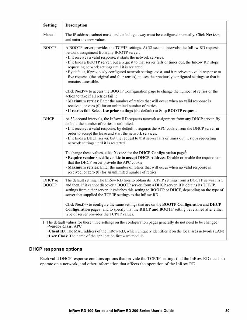
Setting Description
Manual The IP address, subnet mask, and default gateway must be configured manually. Click Next>>, and enter the new values.
BOOTP A BOOTP server provides the TCP/IP settings. At 32-second intervals, the InRow RD requests network assignment from any BOOTP server:• If it receives a valid response, it starts the network services.• If it finds a BOOTP server, but a request to that server fails or times out, the InRow RD stops
requesting network settings until it is restarted.• By default, if previously configured network settings exist, and it receives no valid response to
five requests (the original and four retries), it uses the previously configured settings so that it remains accessible.
Click Next>> to access the BOOTP Configuration page to change the number of retries or the action to take if all retries fail 1:• Maximum retries: Enter the number of retries that will occur when no valid response is
received, or zero (0) for an unlimited number of retries.• If retries fail: Select Use prior settings (the default) or Stop BOOTP request.
DHCP At 32-second intervals, the InRow RD requests network assignment from any DHCP server. By default, the number of retries is unlimited.• If it receives a valid response, by default it requires the APC cookie from the DHCP server in
order to accept the lease and start the network services.• If it finds a DHCP server, but the request to that server fails or times out, it stops requesting
network settings until it is restarted.
To change these values, click Next>> for the DHCP Configuration page1:• Require vendor specific cookie to accept DHCP Address: Disable or enable the requirement
that the DHCP server provide the APC cookie.• Maximum retries: Enter the number of retries that will occur when no valid response is
received, or zero (0) for an unlimited number of retries.
DHCP & BOOTP
The default setting. The InRow RD tries to obtain its TCP/IP settings from a BOOTP server first, and then, if it cannot discover a BOOTP server, from a DHCP server. If it obtains its TCP/IP settings from either server, it switches this setting to BOOTP or DHCP, depending on the type of server that supplied the TCP/IP settings to the InRow RD.
Click Next>> to configure the same settings that are on the BOOTP Configuration and DHCP Configuration pages1 and to specify that the DHCP and BOOTP setting be retained after either type of server provides the TCP/IP values.
1. The default values for these three settings on the configuration pages generally do not need to be changed: •Vendor Class: APC•Client ID: The MAC address of the InRow RD, which uniquely identifies it on the local area network (LAN)•User Class: The name of the application firmware module
30InRow RD 100-Series and InRow RD 200-Series User’s Guide
Vendor Specific Information (option 43). The InRow RD uses this option in a DHCP response to determine whether the DHCP response is valid. This option contains up to two APC-specific options in a TAG/LEN/DATA format: the APC Cookie and the Boot Mode Transition.
• APC Cookie. Tag 1, Len 4, Data “1APC”
Option 43 communicates to the InRow RD that a DHCP server is configured to service APC devices. By default, this DHCP response option must contain the APC cookie for the InRow RD to accept the lease.
To disable the requirement of an APC cookie, see “DHCP” on page 30.
Following, in hexadecimal format, is an example of a Vendor Specific Information option that contains the APC cookie:
Option 43 = 0x01 0x04 0x31 0x41 0x50 0x43
• Boot Mode Transition. Tag 2, Len 1, Data 1/2
This option 43 setting enables or disables Remain in DHCP & BOOTP mode after accepting TCP/IP settings, which, by default, is disabled.
• A data value of 1 enables Remain in DHCP & BOOTP mode after accepting TCP/IP settings. Whenever the InRow RD reboots, it will request its network assignment first from a BOOTP server, and then, if necessary, from a DHCP server.
• A data value of 2 disables the option Remain in DHCP & BOOTP mode after accepting TCP/IP settings option. The TCP/IP Configuration setting option switches to DHCP when the InRow RD accepts the DHCP response. Whenever the InRow RD reboots, it will request its network assignment from a DHCP server only.
Following, in hexadecimal format, is an example of a Vendor Specific Information option that contains the APC cookie and the disable setting for Boot Mode Transition:
Option 43 = 0x01 0x04 0x31 0x41 0x50 0x43 0x02 0x01 0x01
TCP/IP options. The InRow RD uses the following options within a valid DHCP response to define its TCP/IP settings. All of these options except the first are described in RFC2132.
• IP Address (from the yiaddr field of the DHCP response, described in RFC2131): The IP address that the DHCP server is leasing to the InRow RD.
• Subnet Mask (option 1): The Subnet Mask value that the InRow RD needs to operate on the network.
• Router, i.e., Default Gateway (option 3): The default gateway address that the InRow RD needs to operate on the network.
• IP Address Lease Time (option 51): The time duration for the lease of the IP Address to the InRow RD.
• Renewal Time, T1 (option 58): The time that the InRow RD must wait after an IP address lease is assigned before it can request a renewal of that lease.
• Rebinding Time, T2 (option 59): The time that the InRow RD must wait after an IP address lease is assigned before it can seek to rebind that lease.
InRow RD 100-Series and InRow RD 200-Series User’s Guide31
Other options. The InRow RD also uses these options within a valid DHCP response. All of these options except the last are described in RFC2132.
• Network Time Protocol Servers (option 42): Up to two NTP servers (primary and secondary) that the InRow RD can use.
• Time Offset (option 2): The offset of the InRow RD's subnet, in seconds, from Coordinated Universal Time (UTC).
• Domain Name Server (option 6): Up to two Domain Name System (DNS) servers (primary and secondary) that the InRow RD can use.
• Host Name (option 12): The host name that the InRow RD will use (32-character maximum length).
• Domain Name (option 15): The domain name that the InRow RD will use (64-character maximum length).
• Boot File Name (from the file field of the DHCP response, described in RFC2131): The fully qualified directory-path to an user configuration file (.ini file) to download. The siaddr field of the DHCP response specifies the IP address of the server from which the InRow RD will download the .ini file. After the download, the InRow RD uses the .ini file as a boot file to reconfigure its settings.
Port Speed
Path: Administration > Network > Port Speed
The Port Speed setting defines the communication speed of the TCP/IP port.
• For Auto-negotiation (the default), Ethernet devices negotiate to transmit at the highest possible speed, but if the supported speeds of two devices are unmatched, the slower speed is used.
• Alternatively, you can choose 10 Mbps or 100 Mbps, each with the option of half-duplex (communication in only one direction at a time) or full-duplex (communication in both directions on the same channel simultaneously).
DNSPath: Administration > Network > DNS > options
Use the options under DNS on the left navigation menu to configure and test the Domain Name System (DNS):
• Select servers to specify the IP addresses of the primary and optional secondary DNS server. For the InRow RD to send e-mail, at least the IP address of the primary DNS server must be defined.
– The InRow RD waits up to 15 seconds for a response from the primary DNS server or the secondary DNS server (if a secondary DNS server is specified). If the InRow RD does not receive a response within that time, e-mail cannot be sent. Therefore, use DNS servers on the same segment as the InRow RD or on a nearby segment (but not across a wide-area network [WAN]).
– After you define the IP addresses of the DNS servers, verify that DNS is working correctly by entering the DNS name of a computer on your network to look up the IP address for that computer.
32InRow RD 100-Series and InRow RD 200-Series User’s Guide

• Select naming to define the host name and domain name of the InRow RD:– Host Name: After you configure a host name here and a domain name in the Domain Name
field, users can enter a host name in any field in the InRow RD interface (except e-mail addresses) that accepts a domain name.
– Domain Name: You need to configure the domain name here only. In all other fields in the InRow RD interface (except e-mail addresses) that accept domain names, the InRow RD adds this domain name when only a host name is entered.
• To override all instances of the expansion of a specified host name by the addition of the domain name, set the domain name field to its default, somedomain.com, or to 0.0.0.0.
• To override the expansion of a specific host name entry (or example, when defining a trap receiver) include a trailing period. The InRow RD recognizes a host name with a trailing period (such as mySnmpServer.) as if it were a fully qualified domain name and does not append the domain name.
• Select test to send a DNS query that tests the setup of your DNS servers: – As Query Type, select the method to use for the DNS query:
• by Host: the URL name of the server• by FQDN: the fully qualified domain name• by IP: the IP address of the server• by MX: the Mail Exchange used by the server
– As Query Question, identify the value to be used for the selected query type:
– View the result of the test DNS request in the Last Query Response field.
Query Type Selected Query Question to Use
by Host The URL
by FQDN The fully qualified domain name, my_server.my_domain.
by IP The IP address
by MX The Mail Exchange address
InRow RD 100-Series and InRow RD 200-Series User’s Guide33
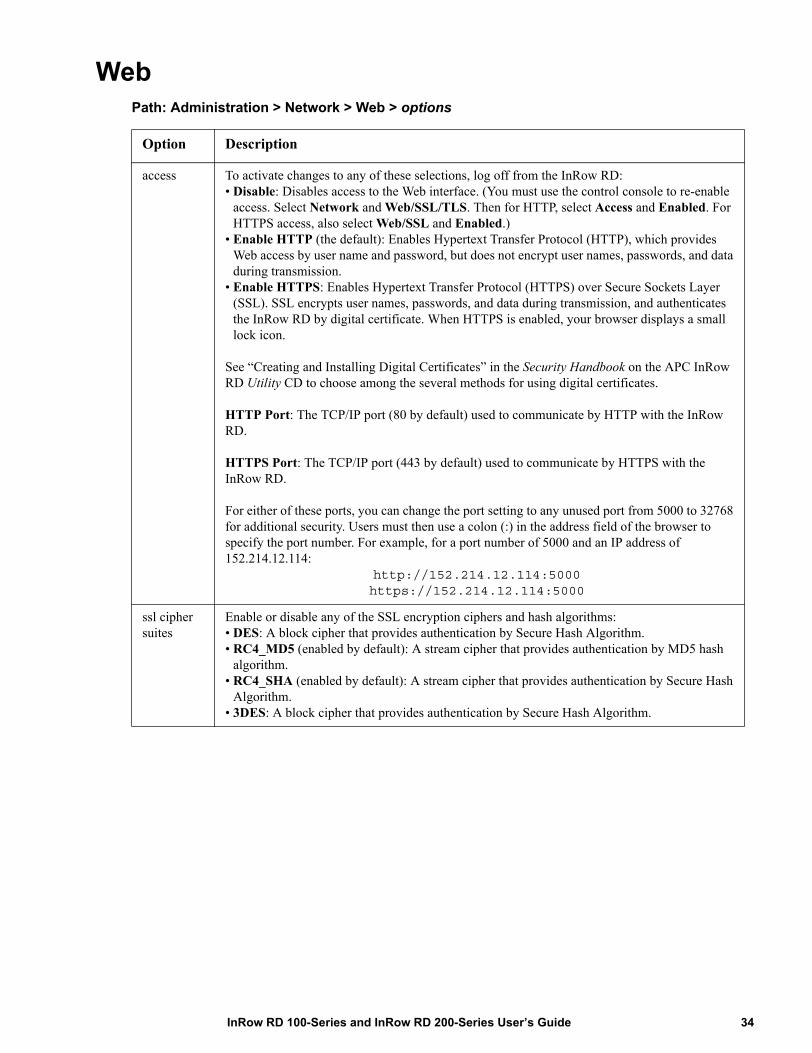
WebPath: Administration > Network > Web > options
Option Description
access To activate changes to any of these selections, log off from the InRow RD:• Disable: Disables access to the Web interface. (You must use the control console to re-enable
access. Select Network and Web/SSL/TLS. Then for HTTP, select Access and Enabled. For HTTPS access, also select Web/SSL and Enabled.)
• Enable HTTP (the default): Enables Hypertext Transfer Protocol (HTTP), which provides Web access by user name and password, but does not encrypt user names, passwords, and data during transmission.
• Enable HTTPS: Enables Hypertext Transfer Protocol (HTTPS) over Secure Sockets Layer (SSL). SSL encrypts user names, passwords, and data during transmission, and authenticates the InRow RD by digital certificate. When HTTPS is enabled, your browser displays a small lock icon.
See “Creating and Installing Digital Certificates” in the Security Handbook on the APC InRow RD Utility CD to choose among the several methods for using digital certificates.
HTTP Port: The TCP/IP port (80 by default) used to communicate by HTTP with the InRow RD.
HTTPS Port: The TCP/IP port (443 by default) used to communicate by HTTPS with the InRow RD.
For either of these ports, you can change the port setting to any unused port from 5000 to 32768 for additional security. Users must then use a colon (:) in the address field of the browser to specify the port number. For example, for a port number of 5000 and an IP address of 152.214.12.114:
http://152.214.12.114:5000https://152.214.12.114:5000
ssl cipher suites
Enable or disable any of the SSL encryption ciphers and hash algorithms:• DES: A block cipher that provides authentication by Secure Hash Algorithm.• RC4_MD5 (enabled by default): A stream cipher that provides authentication by MD5 hash
algorithm.• RC4_SHA (enabled by default): A stream cipher that provides authentication by Secure Hash
Algorithm.• 3DES: A block cipher that provides authentication by Secure Hash Algorithm.
34InRow RD 100-Series and InRow RD 200-Series User’s Guide
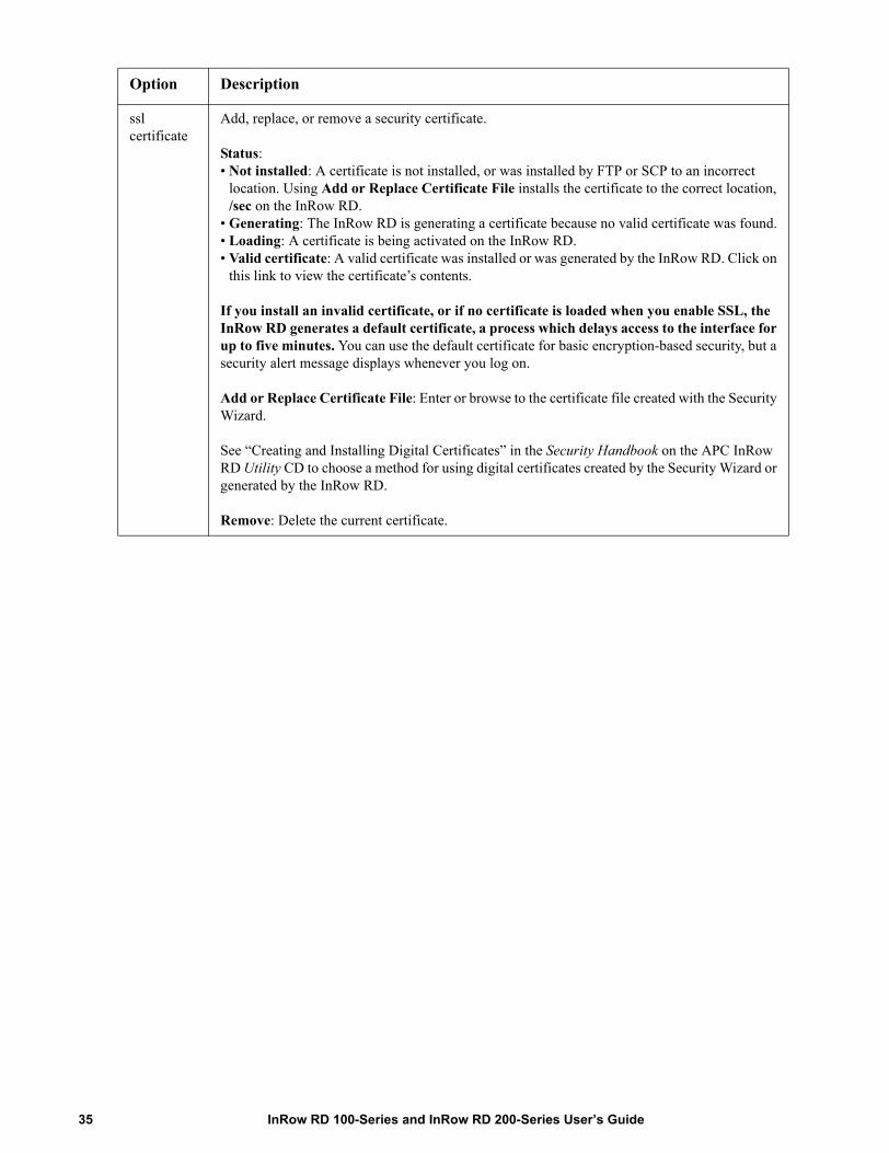
ssl certificate
Add, replace, or remove a security certificate.
Status:• Not installed: A certificate is not installed, or was installed by FTP or SCP to an incorrect
location. Using Add or Replace Certificate File installs the certificate to the correct location, /sec on the InRow RD.
• Generating: The InRow RD is generating a certificate because no valid certificate was found.• Loading: A certificate is being activated on the InRow RD.• Valid certificate: A valid certificate was installed or was generated by the InRow RD. Click on
this link to view the certificate’s contents.
If you install an invalid certificate, or if no certificate is loaded when you enable SSL, the InRow RD generates a default certificate, a process which delays access to the interface for up to five minutes. You can use the default certificate for basic encryption-based security, but a security alert message displays whenever you log on.
Add or Replace Certificate File: Enter or browse to the certificate file created with the Security Wizard.
See “Creating and Installing Digital Certificates” in the Security Handbook on the APC InRow RD Utility CD to choose a method for using digital certificates created by the Security Wizard or generated by the InRow RD.
Remove: Delete the current certificate.
Option Description
InRow RD 100-Series and InRow RD 200-Series User’s Guide35

Console Path: Administration > Network > Console > options
Option Description
access Choose one of the following for access by Telnet or Secure SHell (SSH):• Disable: Disables all access to the control console.• Enable Telnet (the default): Telnet transmits user names, passwords, and data without
encryption.• Enable SSH v1 and v2: Do not enable both versions 1 and 2 of SSH unless you require both.
They use extensive processing power.)• Enable SSH v1 only: SSH version 1 encrypts user names, passwords, and data for
transmission. There is little or no delay as you log on.• Enable SSH v2 only: SSH version 2 transmits user names, passwords, and data in encrypted
form with more protection than version 1 from attempts to intercept, forge, or alter data during transmission. There is a noticeable delay as you log on.
Configure the ports to be used by these protocols: • Telnet Port: The Telnet port used to communicate with the InRow RD (23 by default). You
can change the port setting to any unused port from 5000 to 32768 for additional security. Users must then use a colon (:) or a space, as required by your Telnet client program, to specify the non-default port. For example, for port 5000 and an IP address of 152.214.12.114, your Telnet client requires one of the these commands:
telnet 152.214.12.114:5000telnet 152.214.12.114 5000
• SSH Port: The SSH port used to communicate with the InRow RD (22 by default). You can change the port setting to any unused port from 5000 to 32768 for additional security. See the documentation for your SSH client for the command line format required to specify a non-default port.
ssh encryption
Enable or disable encryption algorithms (block ciphers) compatible with SSH version 1 or version 2 clients:
If your SSH v1 client cannot use Blowfish, you must also enable DES.
Your SSH v2 client selects the enabled algorithm that provides the highest security. If the client cannot use the default algorithms (3DES or Blowfish), enable an AES algorithm that it can use (AES 128 or AES 256).
36InRow RD 100-Series and InRow RD 200-Series User’s Guide

Note: To use SSH, you must have an SSH client installed. Most Linux and other UNIX®
platforms include an SSH client, but Microsoft Windows operating systems do not. Clients are available from various vendors.
SNMPSNMPv1
Path: Administration > Network > SNMPv1 > options
All user names, passwords, and community names for SNMP are transferred over the network as plain text. If your network requires the high security of encryption, disable SNMP access or set the access for each community to Read. (A community with Read access can receive status information and use SNMP traps.)
When using InfraStruXure Central to manage the InRow RD on the public network of an InfraStruXure system, you must have SNMP enabled in the InRow RD interface. Read access will allow InfraStruXure Central to receive traps from the InRow RD, but Write access is required while you use the interface of the InRow RD to set InfraStruXure Central as a trap receiver.
For detailed information on enhancing and managing the security of your system, see the Security Handbook, available on the APC InRow RD Utility CD or from the APC Web site, www.apc.com.
ssh host key Status indicates the status of the host key (private key):• SSH Disabled: No host key in use: When disabled, SSH cannot use a host key.• Generating: The InRow RD is creating a host key because no valid host key was found.• Loading: A host key is being activated on the InRow RD.• Valid: One of the following valid host keys is in the /sec directory (the required location on
the InRow RD): •A 1024-bit host key created by the APC Security Wizard•A 768-bit RSA host key generated by the InRow RD
Add or Replace: Browse to and upload a host key file created by the Security Wizard:
If you use FTP or Secure CoPy (SCP) instead to transfer the host key file, you must specify the /sec directory as the target location in the command.
To use the APC Security Wizard, see the Security Handbook on the APC InRow RD Utility CD.
NOTE: To reduce the time required to enable SSH, create and upload a host key in advance. If you enable SSH with no host key loaded, the InRow RD takes up to 5 minutes to create a host key, and the SSH server is not accessible during that time.
Remove: Remove the current host key.
Option Description
InRow RD 100-Series and InRow RD 200-Series User’s Guide37

SNMPv3
Path: Administration > Network > SNMPv3 > options
For SNMP GETs, SETs, and trap receivers, SNMPv3 uses a system of user profiles to identify users. An SNMPv3 user must have a user profile assigned in the MIB software program to perform GETs and SETs, browse the MIB, and receive traps.
Note: To use SNMPv3, you must have a MIB program that supports SNMPv3.
The InRow RD supports only MD5 authentication and DES encryption.
Option Description
access Enable SNMPv1 Access: Enables SNMP version 1 as a method of communication with this device.
access control
You can configure up to four access control entries to specify which NMSs have access to this device. The opening page for access control, by default, assigns one entry to each of the four available SNMPv1 communities, but you can edit these settings to apply more than one entry to any community to grant access by several specific IP addresses, host names, or IP address masks. To edit the access control settings for a community, click its community name.• If you leave the default access control entry unchanged for a community, that community has
access to this device from any location on the network. • If you configure multiple access control entries for one community name, the limit of four entries
requires that one or more of the other communities must have no access control entry. If no access control entry is listed for a community, that community has no access to this device.
Community Name: The name that a Network Management System (NMS) must use to access the community. The maximum length is 15 ASCII characters, and the default community names for the four communities are public, private, public2, and private2.
NMS IP/Host Name: The IP address, IP address mask, or host name that controls access by NMSs. A host name or a specific IP address (such as 149.225.12.1) allows access only by the NMS at that location. IP addresses that contain 255 restrict access as follows:• 149.225.12.255: Access only by an NMS on the 149.225.12 segment.• 149.225.255.255: Access only by an NMS on the 149.225 segment. • 149.255.255.255: Access only by an NMS on the 149 segment.• 0.0.0.0 (the default setting) which can also be expressed as 255.255.255.255: Access by any
NMS on any segment.
Access Type: The actions an NMS can perform through the community.• Read: GETS only, at any time • Write: GETS at any time, and SETS when no user is logged onto the Web interface or control
console.• Write+: GETS and SETS at any time. • Disabled: No GETS or SETS at any time.
Option Description
access SNMPv3 Access: Enables SNMPv3 as a method of communication with this device.
38InRow RD 100-Series and InRow RD 200-Series User’s Guide

user profiles
By default, lists the settings of four user profiles, configured with the user names apc snmp profile1 through apc snmp profile4, and no authentication and no privacy (no encryption). To edit the following settings for a user profile, click a user name in the list.
User Name: The identifier of the user profile. SNMP version 3 maps GETs, SETs, and traps to a user profile by matching the user name of the profile to the user name in the data packet being transmitted. A user name can have up to 32 ASCII characters.
Authentication Passphrase: A phrase of 15 to 32 ASCII characters (apc auth passphrase, by default) that verifies that the NMS communicating with this device through SNMPv3 is the NMS it claims to be, that the message has not been changed during transmission, and that the message was communicated in a timely manner, indicating that it was not delayed and that it was not copied and sent again later at an inappropriate time.
Privacy Passphrase: A phrase of 15 to 32 ASCII characters (apc crypt passphrase, by default) that ensures the privacy of the data (by means of encryption) that an NMS is sending to this device or receiving from this device through SNMPv3.
Authentication Protocol: The APC implementation of SNMPv3 supports MD5 authentication. Authentication will not occur unless MD5 is selected as the authentication protocol.
Privacy Protocol: The APC implementation of SNMPv3 supports DES as the protocol for encrypting and decrypting data. Privacy of transmitted data requires that DES is selected as the privacy protocol.
Note: You cannot select the privacy protocol if no authentication protocol is selected.
access control
You can configure up to four access control entries to specify which NMSs have access to this device. The opening page for access control, by default, assigns one entry to each of the four user profiles, but you can edit these settings to apply more than one entry to any user profile to grant access by several specific IP addresses, host names, or IP address masks.• If you leave the default access control entry unchanged for a user profile, all NMSs that use that
profile have access to this device. • If you configure multiple access entries for one user profile, the limit of four entries requires that
one or more of the other user profiles must have no access control entry. If no access control entry is listed for a user profile, no NMS that uses that profile has any access to this device.
To edit the access control settings for a user profile, click its user name.
Access: Mark the Enable checkbox to activate the access control specified by the parameters in this access control entry.
User Name: Select from the drop-down list the user profile to which this access control entry will apply. The choices available are the four user names that you configure through the user profiles option on the left navigation menu.
NMS IP/Host Name: The IP address, IP address mask, or host name that controls access by the NMS. A host name or a specific IP address (such as 149.225.12.1) allows access only by the NMS at that location. An IP address mask that contain 255 restricts access as follows: • 149.225.12.255: Access only by an NMS on the 149.225.12 segment.• 149.225.255.255: Access only by an NMS on the 149.225 segment.• 149.255.255.255: Access only by an NMS on the 149 segment.• 0.0.0.0 (the default setting) which can also be expressed as 255.255.255.255: Access by any
NMS on any segment.
Option Description
InRow RD 100-Series and InRow RD 200-Series User’s Guide39

FTP Server Path: Administration > Network > FTP Server
The FTP server settings enable (by default) or disable access to the FTP server and specify the TCP/IP port (21 by default) that the FTP server uses to communicate with the InRow RD. The FTP server uses both the specified port and the port one number lower than the specified port.
You can change the Port setting to the number of any unused port from 5001 to 32768 for added security. Users must then use a colon (:) to specify the non-default port number. For example, for port 5001 and IP address 152.214.12.114, the command would be ftp 152.214.12.114:5001.
Note: FTP transfers files without encryption. For higher security, disable the FTP server, and transfer files with Secure CoPy (SCP). Selecting and configuring Secure SHell (SSH) enables SCP automatically.
At any time that you want a UPS to be accessible for management by InfraStruXure Central, FTP Server must be enabled in the InRow RD interface.
For detailed information on enhancing and managing the security of your system, see the Security Handbook, available on the APC InRow RD Utility CD or from the APC Web site.
40InRow RD 100-Series and InRow RD 200-Series User’s Guide
Administration: Notification and Logging
Event Actions Path: Administration > Notification > Event Actions > options
Types of notification
You can configure event actions to occur in response to an event or group of events. These actions notify users of the event in any of several ways:
• Active, automatic notification. The specified users or monitoring devices are contacted directly.– E-mail notification– SNMP traps– Syslog notification
• Indirect notification in the event log. If no direct notification is configured, users must check the log to determine which events have occurred.
For another method of indirect notification, see “SNMP” on page 37. SNMP enables an NMS to perform informational queries. For SNMPv1, configuring the most restrictive SNMP access type, READ, enables informational queries without the risk of allowing remote configuration changes.
You can also log system performance data to use for device monitoring. See “Data log” on page 21 for information on how to configure and use this data logging option.
Configuring event actions
Notification Parameters. For events that have an associated clearing event, you can also set the following parameters as you configure events individually or by group, as described in the next two sections. To access the parameters, click the receiver or recipient name.
Parameter Description
Delay x time before sending If the event persists for the specified time, notification is sent. If the condition clears before the time expires, no notification is sent.
Repeat at an interval of x time The notification is sent at the specified interval (e.g., every 2 minutes).
Up to x times During an active event, the notification repeats for this number of times.
Until condition clears The notification is sent repeatedly until the condition clears or is resolved.
InRow RD 100-Series and InRow RD 200-Series User’s Guide41

Configuring by event. To define event actions for an individual event:
1. Select the Administration tab, Notification on the top menu bar, and by event under Event Actions on the left navigation menu.
2. In the list of events, review the marked columns to see whether the action you want is already configured. (By default, logging is configured for all events.)
3. To view or change the current configuration, such as recipients to be notified by e-mail, or Network Management Systems (NMSs) to be notified by SNMP traps, click on the event name.
Note: If no Syslog server is configured, items related to Syslog configuration are not displayed.
When viewing details of an event’s configuration, you can change the configuration, enable or disable event logging or Syslog, or disable notification for specific e-mail recipients or trap receivers, but you cannot add or remove recipients or receivers. To add or remove recipients or receivers, see the following:
• “Identifying Syslog Servers” on page 46• “E-mail recipients” on page 44• “Trap Receivers” on page 45
Configuring by group. To configure a group of events simultaneously:
1. Select the Administration tab, Notification on the top menu bar, and by group under Event Actions on the left navigation menu.
2. Choose how to group events for configuration:– Choose Grouped by severity, and then select all events of one or more severity levels. You
cannot change the severity of an event.– Choose Grouped by category, and then select all events in one or more pre-defined
categories.3. Click Next>> to move from page to page to do the following:
a. Select event actions for the group of events.
• To choose any action except Logging (the default), you must first have at least one relevant recipient or receiver configured.
• If you choose Logging and have configured a Syslog server, select Event Log or Syslog (or both) on the next page.
b. Select whether to leave the newly configured event action enabled for this group of events or to disable the action.
42InRow RD 100-Series and InRow RD 200-Series User’s Guide
Active, Automatic, Direct NotificationE-mail notification
Overview of setup. Use the Simple Mail Transfer Protocol (SMTP) to send e-mail to up to four recipients when an event occurs.
To use the e-mail feature, you must define the following settings:
• The IP addresses of the primary and, optionally, the secondary Domain Name System (DNS) servers. (See “DNS” on page 32.)
• The IP address or DNS name for SMTP Server and From Address. (See “SMTP” on page 43.)• The e-mail addresses for a maximum of four recipients. (See “E-mail recipients” on page 44.)
Note: You can use the To Address setting of the recipients option to send e-mail to a text-based pager.
SMTP.
Path: Administration > Notification > E-mail > server
Setting Description
Local SMTP Server
The IP address or DNS name of the local SMTP server. Note: This definition is required only when SMTP Server is set to Local. See “E-mail recipients” on page 44.
From Address
The contents of the From field in e-mail messages sent by the InRow RD:• In the format user@ [IP_address] (if an IP address is specified as Local SMTP Server)• In the format user@domain (if DNS is configured and the DNS name is specified as Local
SMTP Server) in the e-mail messages.Note: The local SMTP server may require that you use a valid user account on the server for this setting. See the server’s documentation.
InRow RD 100-Series and InRow RD 200-Series User’s Guide43
E-mail recipients.
Path: Administration > Notification > E-mail > recipients
Identify up to four e-mail recipients.
E-mail test (Administration > Notification > E-mail > test). Send a test message to a configured recipient.
Setting Description
To Address The user and domain names of the recipient. To use e-mail for paging, use the e-mail address for the recipient’s pager gateway account (for example, [email protected]). The pager gateway will generate the page.
To bypass the DNS lookup of the mail server’s IP address, use the IP address in brackets instead of the e-mail domain name, e.g., use jsmith@[xxx.xxx.x.xxx] instead of [email protected]. This is useful when DNS lookups are not working correctly.Note: The recipient’s pager must be able to use text-based messaging.
SMTP Server Select one of the following methods for routing e-mail:• Local: Through the InRow RD’s SMTP server. This setting (recommended) ensures that the
e-mail is sent before the InRow RD’s 20-second time-out, and, if necessary, is retried several times. Also do one of the following: • Enable forwarding at the InRow RD’s SMTP server so that it can route e-mail to external
SMTP servers. Typically, SMTP servers are not configured to forward e-mail. Check with the administrator of your SMTP server before changing its configuration to allow forwarding.
• Set up a special e-mail account for the InRow RD to forward e-mail to an external mail account.
• Recipient: Directly to the recipient’s SMTP server. With this setting, the InRow RD tries to send the e-mail only once. On a busy remote SMTP server, the time-out may prevent some e-mail from being sent.
When the recipient uses the InRow RD’s SMTP server, this setting has no effect.
E-mail Generation
Enables (by default) or disables sending e-mail to the recipient.
Format The long format contains Name, Location, Contact, IP address, serial number of the device, date and time, event code, and event description. The short format provides only the event description.
44InRow RD 100-Series and InRow RD 200-Series User’s Guide
SNMP traps
Trap Receivers.
Path: Administration > Notification > SNMP Traps > trap receivers
View trap receivers by NMS IP/Host Name. You can configure up to six trap receivers.
• To open the page for configuring a new trap receiver, click Add Trap Receiver. • To modify or delete a trap receiver, first click its IP address or host name to access its settings. (If
you delete a trap receiver, all notification settings configured under Event Actions for the deleted trap receiver are set to their default values.)
• To specify the trap type for a trap receiver, select either the SNMPv1 or SNMPv3 radio button. For an NMS to receive both types of traps, you must configure two trap receivers for that NMS, one for each trap type.
SNMPv1 option.
SNMPv3 option. Select the identifier of the user profile for this trap receiver. (To view the settings of the user profiles identified by the user names selectable here, choose Network on the top menu bar and user profiles under SNMPv3 on the left navigation menu.)
See “SNMPv3” on page 38 for information on creating user profiles and selecting authentication and encryption methods.
SNMP Trap Test
Path: Administration > Notification > SNMP Traps > test
Last Test Result. The result of the most recent SNMP trap test. A successful SNMP trap test verifies only that a trap was sent; it does not verify that the trap was received by the selected trap receiver. A trap test succeeds if all of the following are true:
• The SNMP version (SNMPv1 or SNMPv3) configured for the selected trap receiver is enabled on this device.
• The trap receiver is enabled.• If a host name is selected for the To address, that host name can be mapped to a valid IP address.
To. Select the IP address or host name to which a test SNMP trap will be sent. If no trap receiver was ever configured, a link to the Trap Receiver configuration page is displayed.
Item Definition
Trap Generation Enable (the default) or disable trap generation for this trap receiver.
NMS IP/Host Name The IP address or host name of this trap receiver. The default, 0.0.0.0, leaves the trap receiver undefined.
Community Name The name (public by default) used as an identifier when SNMPv1 traps are sent to this trap receiver.
Authenticate Traps When this option is enabled (the default), the NMS identified by the NMS IP/Host Name setting will receive authentication traps (traps generated by invalid attempts to log on to this device). To disable that ability, unmark the checkbox.
InRow RD 100-Series and InRow RD 200-Series User’s Guide45

SyslogPath: Logs > Syslog > options
The InRow RD can send messages to up to four Syslog servers when an event occurs. The Syslog servers record events that occur at network devices in a log that provides a centralized record of events.
This user’s guide does not describe Syslog or its configuration values in detail. See RFC3164 for more information about Syslog.
Identifying Syslog Servers.
Path: Logs > Syslog > servers
Syslog Settings.
Path: Logs > Syslog > settings
Setting Definition
Syslog Server
Uses IP addresses or host names to identify from one to four servers to receive Syslog messages sent by the InRow RD.
Port The user datagram protocol (UDP) port that the InRow RD will use to send Syslog messages. The default is 514, the UDP port assigned to Syslog.
Setting Definition
Message Generation
Enables (by default) or disables the Syslog feature.
Facility Code Selects the facility code assigned to the InRow RD’s Syslog messages (User, by default).Note: User best defines the Syslog messages sent by the InRow RD. Do not change this selection unless advised to do so by the Syslog network or system administrator.
Severity Mapping
Maps each severity level of InRow RD or Environment events to available Syslog priorities. You should not need to change the mappings.
The following definitions are from RFC3164:• Emergency: The system is unusable• Alert: Action must be taken immediately• Critical: Critical conditions• Error: Error conditions• Warning: Warning conditions• Notice: Normal but significant conditions• Informational: Informational messages• Debug: Debug-level messages
Following are the default settings for the four Local Priority settings:• Severe is mapped to Critical• Warning is mapped to Warning• Informational is mapped to InfoNote: To disable Syslog messages, see “Configuring event actions” on page 41.
46InRow RD 100-Series and InRow RD 200-Series User’s Guide
Syslog Test and Format example.
Path: Logs > Syslog > test
Send a test message to the Syslog servers configured through the servers option.
1. Select a severity to assign to the test message.2. Define the test message, according to the required message fields
– The priority (PRI): the Syslog priority assigned to the message’s event, and the facility code of messages sent by the InRow RD.
– The Header: a time stamp and the IP address of the InRow RD.– The message (MSG) part:
• The TAG field, followed by a colon and space, identifies the event type.• The CONTENT field is the event text, followed (optionally) by a space and the event
code.For example, APC: Test Syslog is valid.
Queries (SNMP GETs)
See “SNMP” on page 37 for a description of SNMPv1 and SNMPv3 settings that enable an NMS to perform informational queries. With SNMPv1, which does not encrypt data before transmission, configuring the most restrictive SNMP access type (READ) enables informational queries without allowing remote configuration changes.
InRow RD 100-Series and InRow RD 200-Series User’s Guide47

Administration: General Options
Identification Path: Administration > General > Identification
Define values for Name (the device name), Location (the physical location), and Contact (the person responsible for the device) used by the InRow RD’s SNMP agent. These settings are the values used for the MIB-II sysName, sysContact, and sysLocation Object Identifiers (OIDs).
For more information about MIB-II OIDs, see the PowerNet® SNMP Management Information Base (MIB) Reference Guide, available on the Utility CD and the APC Web site, www.apc.com.
Set the Date and TimeMethod
Path: Administration > General > Date & Time > mode
Set the time and date used by the InRow RD. You can change the current settings manually or through a Network Time Protocol (NTP) Server:
• Manual Mode: Do one of the following: – Enter the date and time for the InRow RD.– Mark the check box Apply Local Computer Time to match the date and time settings of the
computer you are using.• Synchronize with NTP Server: Have an NTP Server define the date and time for the InRow RD.
Daylight saving
Path: Administration > General > Date & Time > daylight saving
Enable either traditional United States Daylight Saving Time (DST) or enable and configure a customized daylight saving time to match how Daylight Saving Time is implemented in your local area. DST is disabled by default.
Setting Definition
Primary NTP Server Enter the IP address or domain name of the primary NTP server.
Secondary NTP Server Enter the IP address or domain name of the secondary NTP server, when a secondary server is available.
Time Zone Select a time zone. The number of hours preceding each time zone in the list is the offset from Coordinated Universal Time (UTC), formerly Greenwich Mean Time).
Update Interval Define how often, in hours, the InRow RD accesses the NTP Server for an update. Minimum: 1; Maximum: 8760 (1 year).
Update Using NTP Now Initiate an immediate update of date and time by the NTP Server.
48InRow RD 100-Series and InRow RD 200-Series User’s Guide
When customizing Daylight Saving Time (DST):
• If the local DST always starts or ends on the fourth occurrence of a specific weekday of a month (e.g, the fourth Sunday), choose Fourth/Last. If a fifth Sunday occurs in that month in a subsequent year, the time setting still changes on the fourth Sunday.
• If the local DST always starts or ends on the last occurrence of a specific weekday of a month, whether it is the fourth or the fifth occurrence, choose Fifth/Last.
Format
Path: Administration > General > Date & Time > date format
Select the numerical format in which to display all dates in this user interface. In the selections, each letter m (for month), d (for day), and y (for year) represents one digit. Single-digit days and months are displayed with a leading zero.
Use an .ini File Path: Administration > General > User Config File
Use the settings from one InRow RD to configure another. Retrieve the config.ini file from the configured InRow RD, customize that file (e.g., to change the IP address), and upload the customized file to the new InRow RD. The file name can be up to 64 characters, and must have the.ini suffix.
To retrieve and customize the file of a configured InRow RD, see “How to Export Configuration Settings” on page 55.
Instead of uploading the file to one InRow RD, you can export the file to multiple InRow RDs by using an FTP or SCP script or a batch file and the APC .ini file utility, available from www.apc.com/tools/download.
Temperature UnitsPath: Administration > General > Preferences
Event Log Color Coding. Click in the box to select Enable or Disable.
Temperature Scale. Select the temperature scale (Fahrenheit or Celsius) in which to display all temperature measurements in this user interface.
Status Reports the progress of the upload. The upload succeeds even if the file contains errors, but a system event r reports the errors in the event log.
Upload Browse to the customized file and upload it so that the current InRow RD can use it to set its own configuration.
InRow RD 100-Series and InRow RD 200-Series User’s Guide49
Reset the Interface Path: Administration > General > Reset/Reboot
Serial ModbusPath: Administration > General > Serial Modbus
Check the Access box to Enable or Disable Modbus. Select the Baud Rate by clicking on one of the radio buttons by the baud rate options (9600 or 19200 bps). Specify a Target Unique ID by entering a number from 1 to 247 in the box. Then select Apply.
Modbus defines a request/response message structure for a client/server environment. The APC implementation of Modbus uses Remote Terminal Unit (RTU) mode. You can use Modbus to view the InRow RD through your building management system interface. It is read-only.
• The Modbus interface supports 2-wire RS-485.• Modbus runs at 9600 or 19200 bps.
The Modbus register map for the InRow RD defines the data (type, location, and valid responses) available through Modbus. To download the latest Modbus regester map, go to the APC web site, search by part number, and click the link to the register map in the list of documentation. Check the publication date at the start of the file.
Configuring Links Path: Administration > General > Quick Links
Select the Administration tab, General on the top menu bar, and Quick Links on the left navigation menu to view and change the URL links displayed at the bottom left of each page of the interface.
By default, these links access the following Web pages:
• Link 1: The home page of the APC Web site. • Link 2: A page where you can use samples of APC Web-enabled products.• Link 3: The home page of the APC Remote Monitoring Service.
Action Definition
Reboot Management Interface
Restarts the interface of the InRow RD.
Reset All1 Select Exclude TCP/IP to reset all values except TCP/IP; clear Exclude TCP/IP to reset all configuration values.
Reset Only1 TCP/IP settings: Set TCP/IP Configuration to DHCP & BOOTP, its default setting, requiring that the InRow RD receive its TCP/IP settings from a DHCP or BOOTP server. See “TCP/IP and Communication Settings” on page 29.
Event configuration: Reset all changes to event configuration, by event and by group, to their default settings.
1. Resetting may take up to a minute.
50InRow RD 100-Series and InRow RD 200-Series User’s Guide
To reconfigure any of the following, click the link name in the Display column:
• Display: The short link name displayed on each interface page• Name: A name that fully identifies the target or purpose of the link• Address: Any URL — for example, the URL of another device or server
About the InRow RD Path: Administration > General > About
The hardware information is especially useful to APC Customer Support to troubleshoot problems with the InRow RD. The serial number and MAC address are also available on the InRow RD itself.
Firmware information for the Application Module and APC OS (AOS) indicates the name, the firmware version, and the date and time each firmware module was created. This information is also useful in troubleshooting and enables you to determine if updated firmware is available at the APC Web site.
Management Uptime is the length to time the interface has been running continuously.
InRow RD 100-Series and InRow RD 200-Series User’s Guide51

APC Device IP Configuration Wizard
Capabilities, Requirements, and InstallationHow to use the Wizard to configure TCP/IP settings
The APC Device IP Configuration Wizard configures the IP address, subnet mask, and default gateway of one or more InRow RDs. You can use the Wizard in either of the following ways:
• Remotely over your TCP/IP network to discover and configure unconfigured InRow RDs on the same network segment as the computer running the Wizard.
• Through a direct connection from a serial port of your computer to the InRow RD to configure or reconfigure it.
System requirements
The Wizard runs on Microsoft Windows 2000, Windows 2003, and Windows XP operating systems.
Installation
To install the Wizard from the Utility CD:
1. If autorun is enabled, the user interface of the CD starts when you insert the CD. Otherwise, open the file contents.htm on the CD.
2. Click Device IP Configuration Wizard and follow the instructions.To install the Wizard from a downloaded executable file:
1. Go to www.apc/tools/download.2. Download the Device IP Configuration Wizard.3. Run the executable file in the folder to which you downloaded it.
52InRow RD 100-Series and InRow RD 200-Series User’s Guide
Use the WizardNote: Most software firewalls must be temporarily disabled for the Wizard to discover unconfigured InRow RDs.
Launch the WizardThe installation creates a shortcut link in the Start menu to launch the Wizard.
Configure the basic TCP/IP settings remotely
Prepare to configure the settings. Before you run the Wizard:
1. Contact your network administrator to obtain valid TCP/IP settings.2. If you are configuring multiple unconfigured InRow RDs, obtain the MAC address of each one to
identify it when the Wizard discovers it. (The Wizard displays the MAC address on the screen on which you then enter the TCP/IP settings.)– The MAC address is on a label on the InRow RD. – You can also obtain the MAC address from the Quality Assurance slip that came with the
InRow RD.Run the Wizard to perform the configuration. To discover and configure unconfigured InRow RDs over the network:
1. From the Start menu, launch the Wizard. The Wizard detects the first InRow RD that is not configured.
2. Select Remotely (over the network), and click Next >.3. Enter the system IP, subnet mask, and default gateway for the InRow RD identified by the MAC
address. Click Next >.
On the Transmit Current Settings Remotely screen, if you select the Start a Web browser when finished check box, the default Web browser connects to the InRow RD after the Wizard transmits the settings.
4. Click Finish to transmit the settings. If the IP address you entered is in use on the network, the Wizard prompts you to enter an IP address that is not in use. Enter a correct IP address, and click Finish.
5. If the Wizard finds another unconfigured InRow RD, it displays the screen to enter TCP/IP settings. Repeat this procedure beginning at step 3, or to skip the InRow RD whose MAC address is currently displayed, click Cancel.
InRow RD 100-Series and InRow RD 200-Series User’s Guide53
Configure or reconfigure the TCP/IP settings locally
1. Contact your network administrator to obtain valid TCP/IP settings.2. Connect the serial configuration cable (which came with the InRow RD) from an available
communications port on your computer to the serial port of the card or device. Make sure no other application is using the computer port.
3. From the Start menu, launch the Wizard application. 4. If the InRow RD is not configured, wait for the Wizard to detect it. Otherwise, click Next>.5. Select Locally (through the serial port), and click Next >.6. Enter the system IP, subnet mask, and default gateway for the InRow RD, and click Next >.7. On the Transmit Current Settings Remotely screen, if you select the Start a Web browser
when finished check box, the default Web browser connects to the InRow RD after the Wizard transmits the settings.
8. Click Finish to transmit the TCP/IP settings. If the IP address you entered is in use on the network, the Wizard prompts you to enter an IP address that is not in use. Enter a correct IP address, and click Finish.
9. If you selected Start a Web browser when finished in step 6, you can now configure other parameters through the Web interface of the device.
54InRow RD 100-Series and InRow RD 200-Series User’s Guide
How to Export Configuration Settings
Retrieving and Exporting the .ini FileSummary of the procedure
An Administrator can retrieve the .ini file of a cooling unit and export it to another cooling unit or to multiple cooling units.
1. Configure one cooling unit to have the settings you want to export.2. Retrieve the .ini file from that cooling unit.3. Customize the file to change at least the TCP/IP settings. 4. Use a file transfer protocol supported by the cooling unit to transfer a copy to one or more other
cooling units. For a transfer to multiple cooling units, use an FTP or SCP script or the APC .ini file utility.
Each receiving cooling unit uses the file to reconfigure its own settings and then deletes it.
Contents of the .ini file
The config.ini file you retrieve from the cooling unit contains the following:
• section headings and keywords (only those supported for the device from which you retrieve the file): Section headings are category names enclosed in brackets ([ ]). Keywords, under each section heading, are labels describing specific cooling unit settings. Each keyword is followed by an equals sign and a value (either the default or a configured value).
• The Override keyword: With its default value, this keyword prevents the exporting of one or more keywords and their device-specific values, e.g., in the [NetworkTCP/IP] section, the default value for Override (the MAC address of the cooling unit) blocks the exporting of values for the SystemIP, SubnetMask, DefaultGateway, and BootMode.
Detailed procedures
Retrieving. To set up and retrieve an .ini file to export:
1. If possible, use the interface of a cooling unit to configure it with the settings to export. Directly editing the .ini file risks introducing errors.
2. To use FTP to retrieve config.ini from the configured cooling unit:a. Open a connection to the cooling unit, using its IP address:
ftp> open ip_address
b. Log on using the Administrator user name and password.c. Retrieve the config.ini file containing the cooling unit’s settings:
ftp> get config.ini
The file is written to the folder from which you launched FTP.
To retrieve configuration settings from multiple cooling units and export them to other cooling units, see Release Notes: ini File Utility, version 1.0, available on the Utility CD and at www.apc.com.
InRow RD 100-Series and InRow RD 200-Series User’s Guide55

Customizing. You must customize the file before you export it.
1. Use a text editor to customize the file. – Section headings, keywords, and pre-defined values are not case-sensitive, but string values
that you define are case-sensitive.– Use adjacent quotation marks to indicate no value. For example, LinkURL1="" indicates that
the URL is intentionally undefined.– Enclose in quotation marks any values that contain leading or trailing spaces or are already
enclosed in quotation marks.– To export scheduled events, configure the values directly in the .ini file.– To export a system time with the greatest accuracy, if the receiving cooling units can access a
Network Time Protocol server, configure enabled for NTPEnable:
NTPEnable=enabled
Alternatively, reduce transmission time by exporting the [SystemDate/Time] section as a separate .ini file.
– To add comments, start each comment line with a semicolon (;).2. Copy the customized file to another file name in the same folder:
– The file name can have up to 64 characters and must have the .ini suffix.– Retain the original customized file for future use. The file that you retain is the only record
of your comments.Transferring the file to a single cooling unit. To transfer the .ini file to another cooling unit, do either of the following:
• From the Web interface of the receiving cooling unit, select the Administration tab, General on the top menu bar, and User Config File on the left navigation menu. Enter the full path of the file, or use Browse.
• Use any file transfer protocol supported by cooling units, i.e., FTP, FTP Client, SCP, or TFTP). The following example uses FTP:
a. From the folder containing the copy of the customized .ini file, use FTP to log in to the cooling unit to which you are exporting the .ini file:
ftp> open ip_address
b. Export the copy of the customized .ini file to the root directory of the receiving cooling unit:
ftp> put filename.ini
Exporting the file to multiple cooling units. To export the .ini file to multiple cooling units:
• Use FTP or SCP, but write a script that incorporates and repeats the steps used for exporting the file to a single cooling unit.
• Use a batch processing file and the APC .ini file utility.To create the batch file and use the utility, see Release Notes: ini File Utility, version 1.0 on the Utility CD.
56InRow RD 100-Series and InRow RD 200-Series User’s Guide
The Upload Event and Error MessagesThe event and its error messages
The following event occurs when the receiving cooling unit completes using the .ini file to update its settings.
Configuration file upload complete, with number valid values
If a keyword, section name, or value is invalid, the upload by the receiving cooling unit succeeds, and additional event text states the error.
Messages in config.ini
A device associated with the cooling unit from which you download the config.ini file must be discovered successfully in order for its configuration to be included. If the device is not present or, for another reason, is not discovered, the config.ini file contains a message under the appropriate section name, instead of keywords and values.
If you did not intend to export the configuration of the device as part of the .ini file import, ignore these messages.
Errors generated by overridden values
The Override keyword and its value will generate error messages in the event log when it blocks the exporting of values.
See “Contents of the .ini file” on page 55 for information about which values are overridden.
Because the overridden values are device-specific and not appropriate to export to other cooling units, ignore these error messages. To prevent these error messages, you can delete the lines that contain the Override keyword and the lines that contain the values that they override. Do not delete or change the line containing the section heading.
Event text Description
Configuration file warning: Invalid keyword on line number.
Configuration file warning: Invalid value on line number.
A line with an invalid keyword or value is ignored.
Configuration file warning: Invalid section on line number.
If a section name is invalid, all keyword/value pairs in that section are ignored.
Configuration file warning: Keyword found outside of a section on line number.
A keyword entered at the beginning of the file (i.e., before any section headings) is ignored.
Configuration file warning: Configuration file exceeds maximum size.
If the file is too large, an incomplete upload occurs. Reduce the size of the file, or divide it into two files, and try uploading again.
InRow RD 100-Series and InRow RD 200-Series User’s Guide57

Related TopicsOn Windows operating systems, instead of transferring .ini files, you can use the APC Device IP Configuration Wizard to update the basic TCP/IP settings of cooling units and configure other settings through their user interface.
See “APC Device IP Configuration Wizard” on page 51.
58InRow RD 100-Series and InRow RD 200-Series User’s Guide
File Transfers
Upgrading FirmwareBenefits of upgrading firmware
When you upgrade the firmware on the InRow RD:
• You obtain the latest bug fixes and performance improvements.• New features become available for immediate use.
Keeping the firmware versions consistent across your network ensures that all InRow RDs support the same features in the same manner.
Firmware files (InRow RD)
A firmware version consists of two modules: An APC Operating System (AOS) module and an application module. Each module contains one or more Cyclical Redundancy Checks (CRCs) to protect its data from corruption during transfer.
The APC Operating System (AOS) and application module files used with the InRow RD share the same basic format:
apc_hardware-version_type_firmware-version.bin
• apc: Indicates that this is an APC file.• hardware-version: hw0x identifies the version of the hardware on which you can use this
binary file.• type: Identifies whether the file is for the APC Operating System (AOS) or the application
module for the InRow RD.• version: The version number of the file. • bin: Indicates that this is a binary file.
Obtain the latest firmware versionAutomated upgrade tool for Microsoft Windows systems. An upgrade tool automates the transferring of the firmware modules on any supported Windows operating system. Obtain the latest version of the tool at no cost from www.apc.com/tools/download. At this Web page, find the latest firmware release for your APC product and download the automated tool. Never use the tool for one APC product to upgrade firmware of another.
Manual upgrades, primarily for Linux systems. If no computer on your network is running a Microsoft Windows operating system, you must upgrade the firmware of your InRow RDs by using the separate AOS and application firmware modules.
Obtain the individual firmware modules by downloading the automated tool from www.apcc.com/tools/download, then extracting the firmware files from the tool.
InRow RD 100-Series and InRow RD 200-Series User’s Guide59
To extract the firmware files:
1. Run the tool.2. At the prompts, click Next>, and then specify the directory location to which the files will be
extracted. 3. When the Extraction Complete message displays, close the dialog box.
Firmware File Transfer MethodsTo upgrade the firmware of a InRow RD, use one of these methods:
• From a networked computer running a Microsoft Windows operating system, use the firmware upgrade tool downloaded from the APC Web site.
• From a networked computer on any supported operating system, use FTP or SCP to transfer the individual AOS and application firmware modules.
• For a InRow RD that is not on your network, use XMODEM through a serial connection to transfer the individual firmware modules from your computer to the InRow RD.
Caution: When you transfer individual firmware modules, you must transfer the APC Operating System (AOS) module to the InRow RD before you transfer the application module.
Use FTP or SCP to upgrade one InRow RD
FTP. For you to use FTP to upgrade one InRow RD over the network:
• The InRow RD must be connected to the network, and its system IP, subnet mask, and default gateway must be configured
• The FTP server must be enabled at the InRow RD• The firmware files must be extracted from the firmware upgrade tool (see “To extract the
firmware files:” on page 60)To transfer the files:
1. Open a command prompt window of a computer on the network. Go to the directory that contains the firmware files, and list the files:
C:\>cd\apcC:\apc>dir
For the listed files, xxx represents the firmware version number:
• apc_hw03_aos_xxx.bin
• apc_hw03_application_xxx.bin 2. Open an FTP client session:
C:\apc>ftp
60InRow RD 100-Series and InRow RD 200-Series User’s Guide
3. Type open and the InRow RD’s IP address, and press ENTER. If the port setting for the FTP Server has changed from its default of 21, you must use the non-default value in the FTP command.– For Windows FTP clients, separate a non-default port number from the IP address by a space.
For example:ftp> open 150.250.6.10 21000
– Some FTP clients require a colon instead before the port number.4. Log on as Administrator; apc is the default user name and password.5. Upgrade the AOS. In the example, xxx is the firmware version number:
ftp> binftp> put apc_hw03_aos_xxx.bin
6. When FTP confirms the transfer, type quit to close the session.7. After 20 seconds, repeat step 2 through step 6. In step 5, use the application module file name.
SCP. To use Secure CoPy (SCP) to upgrade firmware for a InRow RD:
1. Identify and locate the firmware modules described in the preceding instructions for FTP.2. Use an SCP command line to transfer the AOS firmware module to the InRow RD. The
following example uses xxx to represent the version number of the AOS module:scp apc_hw03_aos_xxx.bin [email protected]:apc_hw03_aos_xxx.bin
3. Use a similar SCP command line, with the name of the application module, to transfer the second firmware module to the InRow RD.
How to upgrade multiple InRow RDs
Export configuration settings. You can create batch files and use an APC utility to retrieve configuration settings from multiple InRow RDs and export them to other InRow RDs.
See Release Notes: ini File Utility, version 1.0, available on the Utility CD.
Use FTP or SCP to upgrade multiple InRow RDs. To upgrade multiple InRow RDs using an FTP client or using SCP, write a script which automatically performs the procedure.
InRow RD 100-Series and InRow RD 200-Series User’s Guide61
Use XMODEM to upgrade one InRow RD
To upgrade the firmware for one InRow RD that is not on the network, you must extract the firmware files from the firmware upgrade tool (see “To extract the firmware files:” on page 60).
To transfer the files:
1. Obtain the individual firmware modules (the AOS module and the application module) from www.apc.com/tools/download.
2. Select a serial port at the local computer and disable any service that uses the port.3. Connect the provided configuration cable to the selected port and to the serial port at the InRow
RD.4. Run a terminal program such as HyperTerminal, and configure the selected port for 2400 bps, 8
data bits, no parity, 1 stop bit, and no flow control.5. Press ENTER to display the User Name prompt.6. Enter the Administrator user name and password (apc by default for both).7. From the Control Console menu, select System, then Tools, then File Transfer, then
XMODEM; and type Yes at the prompt to continue.8. Select a baud rate, change the terminal program’s baud rate to match your selection, and press
ENTER. A higher baud rate causes faster upgrades.9. From the terminal program’s menu, select the binary AOS file to transfer using XMODEM-CRC.
After the XMODEM transfer is complete, set the baud rate to 2400. The InRow RD automatically restarts.
10.Repeat step 4 through step 9 to install the application module. In step 9, use the application module file name, not the AOS module file name.
11. For information about the format used for firmware modules, see “Firmware files (InRow RD)” on page 59.
Verifying Upgrades and UpdatesVerify the success or failure of the transfer
To verify whether a firmware upgrade succeeded, use the Network menu in the control console and select the FTP Server option to view Last Transfer Result, or use an SNMP GET to the mfiletransferStatusLastTransferResult OID.
62InRow RD 100-Series and InRow RD 200-Series User’s Guide
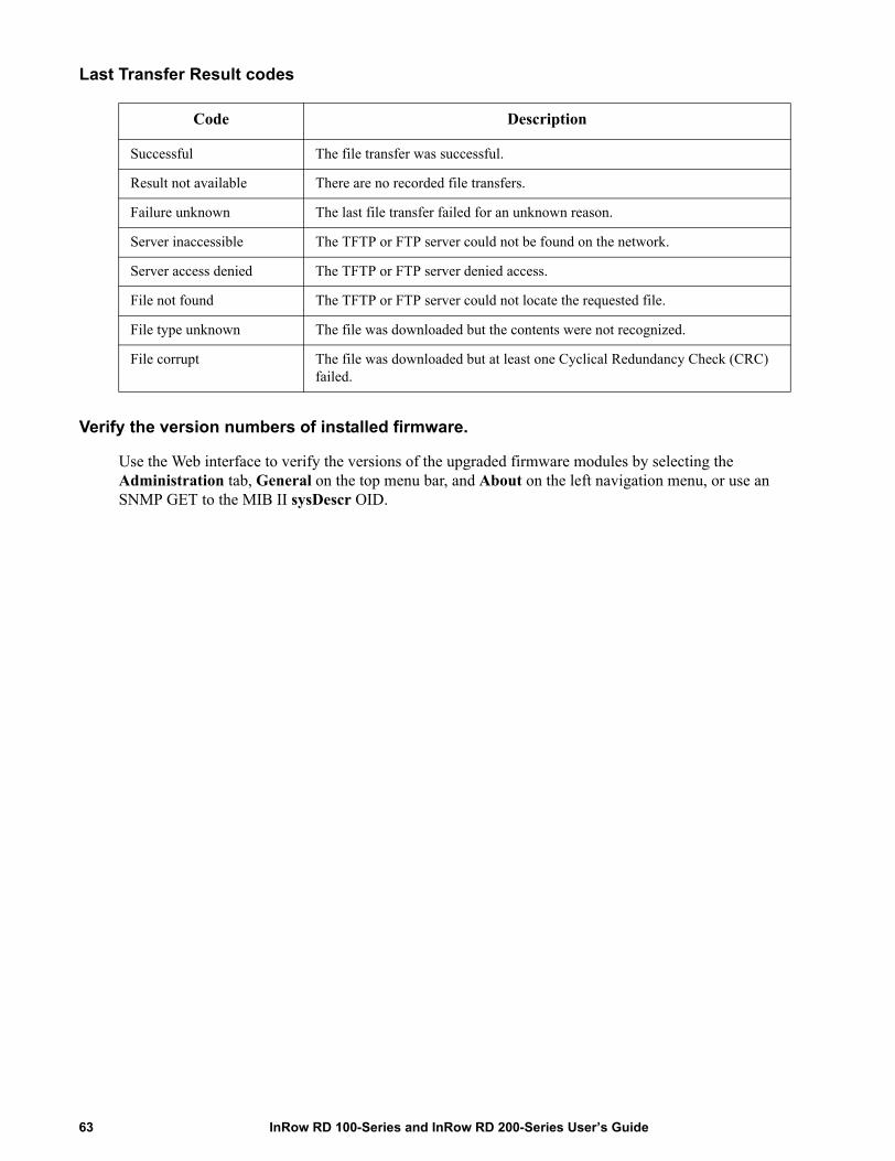
Last Transfer Result codes
Verify the version numbers of installed firmware.
Use the Web interface to verify the versions of the upgraded firmware modules by selecting the Administration tab, General on the top menu bar, and About on the left navigation menu, or use an SNMP GET to the MIB II sysDescr OID.
Code Description
Successful The file transfer was successful.
Result not available There are no recorded file transfers.
Failure unknown The last file transfer failed for an unknown reason.
Server inaccessible The TFTP or FTP server could not be found on the network.
Server access denied The TFTP or FTP server denied access.
File not found The TFTP or FTP server could not locate the requested file.
File type unknown The file was downloaded but the contents were not recognized.
File corrupt The file was downloaded but at least one Cyclical Redundancy Check (CRC) failed.
InRow RD 100-Series and InRow RD 200-Series User’s Guide63

Index
AAbout options
for information about the Management Card 51Access
enabling or disabling methods of accessto the control console 36to the Web interface 34
priority for logging on 2to the control console
locally 7remotely 6
AdministrationNetwork menu 29Notification menu 41
Apply Local Computer Time 48Authenticating users through RADIUS 25Authentication Traps setting 45Automatic log-off for inactivity 28
BBOOTP
BOOTP server providing TCP/IP settings 29Status LED reporting BOOTP requests 4
CCertificates, how to create, view, or remove 35Community Name
for trap receivers 45config.ini file. See User configuration files.Configuring
RADIUS authentication 26Contact identification (whom to contact) 48Control console
configuring access 36Device Manager menu 9navigating menus 9refreshing menus 9structure 9
DData log
importing into spreadsheet 23Log Interval setting 22rotation (archiving) 22using FTP or SCP to retrieve 23
Date & Time settings 48Date format, configuring 49Daylight saving time 48Device IP Configuration Wizard
installation and system requirements 52using the wizard
for local configuration. 54for remote configuration 53
Device Manager menu, control console 9DHCP
APC cookie 31DHCP server providing TCP/IP settings 29Status LED reporting DHCP requests 4
Disablee-mail to a recipient 44encryption algorithms for SSH 36reverse lookup 21SSL cipher suites 34Telnet 36
DNSdefining host and domain names 33query types 33specifying DNS servers by IP address 32
EE-mail
configuring notification parameters 43configuring recipients 44test message 44using for paging 44
Enablee-mail forwarding to external SMTP servers 44e-mail to a recipient 44encryption algorithms for
64InRow RD 100-Series and InRow RD 200-Series User’s Guide

SSH 36reverse lookup 21SSL cipher suites 34Telnet 36versions of SSH 36
Error messagesfrom overridden values in .ini file 57
Ethernet port speed 32Event actions 41
configuring by event 42configuring by group 42
Event logaccessing 9displaying and using 20errors from overridden values in .ini file 57filtering by date or time 20filtering by event 20using FTP del command 24using FTP or SCP to retrieve 23
event.txt filecontents 23importing into spreadsheet 23
FFacility Code (Syslog setting) 46Firmware
benefits of upgrading 59file transfer methods
automated upgrade tool 59FTP or SCP 60XMODEM 62
obtaining the latest version 59upgrading multiple Management Cards 61versions displayed on main screen 7
From Address (SMTP setting) 43FTP
server settings 40transferring firmware files 60using to retrieve event or data log 23
GGeneral menu, Administration tab 48
HHelp
on control console 9
Home Page 13Host keys
adding or replacing 37status 37
Host name of trap receivers 45
IIdentification (Name, Location, and Contact)
in Web interface 48on control console main screen 7
Inactivity timeout 28ini files, See User configuration filesInitial setup 1
JJavaScript, required to launch log in new window 20JavaScript, required to launch log in new
window 21
KKeywords in user configuration file 55
LLast Transfer Result codes 63Launch Log in New Window, JavaScript
requirement. 21Launch Log in New Window, JavaScript
requirement. 20LEDs
Link-RX/TX (10/100) 4status 4
Links, configuration 50Local SMTP Server
defining by IP address or DNS name 43recommended option for routing e-mail 44
Local Users, setting user access 25Location (system value) 48Logging on
control console 6Web interface 11
Login date and time, control console 8Loopback address not to be used as default gateway 1
InRow RD 100-Series and InRow RD 200-Series User’s Guide65
MMain screen of control console
information fields displayed 7status fields displayed 8
MenusControl Console 9General 48Logs 20Network 29Notification 41top menu bar 14
Message Generation (Syslog setting) 46
NNetwork menu 29Network Time Protocol (NTP) 48Network timer, resetting 5NMS IP/Host Name for trap receivers 45Notification menu 41Notification, delaying or repeating 41
OOverride keyword, user configuration file 55
PPaging
by using e-mail 44Passwords
default for each account type 11defining for each account type 25for data log repository 22recovering from lost password 3
Port speed, configuring for Ethernet 32Ports
FTP server 40HTTP and HTTPS 34RADIUS server 26Telnet and SSH 36
Primary NTP Server 48
QQuick Links, configuration 50
RRADIUS
configuration 26server configuration 27supported RADIUS servers 27
Reboot Management Interface 50Recent Events
Device Events on home page 13Recipient SMTP server 44Remote Monitoring Service 50Remote Users
authentication 26setting user access 25
Reset All 50Reset Only 50Restart for inactivity, preventing 5Reverse lookup 21
SSCP
for high-security file transfer 40transferring firmware files 60using to retrieve event or data log 23
Secondary NTP Server 48Section headings, user configuration file 55Severity Mapping (Syslog
setting) 46SMTP server
selecting for e-mail recipients 44SNMP
access and access controlSNMPv1 38SNMPv3 38
authentication traps 45disabling SNMPv1 for high-security systems 37
SSHencryption algorithms 36host keys 37
SSLcipher suites 34configuring cipher suites 34how to create, view, or remove certificates 35
Statuson control console main screen 8
Synchronize with NTP Server,(Date & Time) 48
66InRow RD 100-Series and InRow RD 200-Series User’s Guide
Syslogidentifying the Syslog server and port 46mapping event severity to Syslog priorities 46settings 46test 47
System Name 48
TTCP/IP configuration 29Temperature units (Fahrenheit or Celsius) 49Test
DNS query 33e-mail recipient settings 44RADIUS server path 26Syslog 47trap receiver 45
Time setting 48Time Zone, for synchronizing with NTP
server 48Timeout setting for RADIUS 26To Address, e-mail recipients 44Trap generation, for trap
receivers 45Traps
trap receivers 45Troubleshooting
RADIUS only setting when RADIUS isunavailable 26
UUnit Preference 49Up Time
control console main screen 8in Web interface 51
Update Interval, Date & Time setting 48Update Using NTP Now, Date &
Time setting 48Upgrading firmware 59Upload event 57URL address formats 12User accounts, types 2
User configuration filescontents 55customizing 56exporting system time separately 56messages for undiscovered devices 57overriding device-specific values 55retrieving and exporting 55upload event and error messages 57upload event and error
messages 57using file transfer protocols to transfer 56using the APC utility to retrieve
and transfer the files 55using the file as a boot file with DHCP 32
User namesdefault for each account type 11defining for each account type 25maximum number of characters for RADIUS 25
WWeb interface 11
configuring access 34logging on 11URL address formats 12
XXMODEM to transfer firmware files 62
InRow RD 100-Series and InRow RD 200-Series User’s Guide67


9/2009990-3632
APC Worldwide Customer SupportCustomer support for this or any other APC product is available at no charge in any of the following ways:
• Visit the APC Web site to access documents in the APC Knowledge Base and to submit customer support requests.– www.apc.com (Corporate Headquarters)
Connect to localized APC Web sites for specific countries, each of which provides customer support information.
– www.apc.com/support/Global support searching APC Knowledge Base and using e-support.
• Contact the APC Customer Support Center by telephone or e-mail.– Local, country-specific centers: go to www.apc.com/support/contact for contact information.
For information on how to obtain local customer support, contact the APC representative or other distributors from whom you purchased your APC product.
© 2009 APC by Schneider Electric. APC, the APC logo, InRow, InfraStruXure, and PowerNet are owned by Schneider Electric Industries S.A.S., American Power Conversion Corporation, or their affiliated companies.
All other trademarks are property of their respective owners.