innovative techniques for mitigating arc flash exposure · excessively high arc flash incident...
TRANSCRIPT

© 2007 Eaton Corporation. All rights reserved.
Innovative Techniques for Mitigating Arc Flash Exposure
Presented at
MEMSA 2009 Annual Meeting
&
Technical Symposium

• As more and more industries address arc flash electrical safety
concerns, they are discovering a high risk associated with what
used to be normal maintenance tasks. In many cases, the
excessively high arc flash incident energies make it so all
maintenance must be done with equipment de-energized -- not
always acceptable to the process industries. This paper will
address the multiple ways to significantly lower arc flash
incident energy exposure by new system design and products,
retrofits, retro-fills, equipment modifications, alternate
protection settings, etc. In most cases, NFPA 70E Hazard Risk
Category 2 or lower can be obtained. Examples will be
discussed.
.
INTRODUCTION

.
INTRODUCTION
NFPA 70E defines flash hazard as “a dangerous condition associated with the release of energy caused by an
electric arc.”
What is Arc Flash?

.
INTRODUCTION
Failed 50kA 5kV available fault current 0.5sec

.
INTRODUCTION
Failed 50kA 5kV available fault current 0.5sec

•Large Hydro in Pacific NW
•6.9kV Swgr
•Racking in Breaker
•AF occurred
•One worker injured
•4+ years, $10+ million
INTRODUCTION
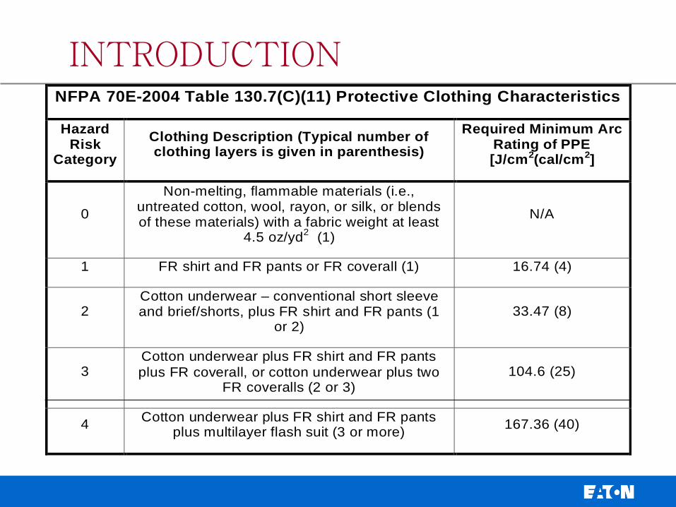
NFPA 70E-2004 Table 130.7(C)(11) Protective Clothing Characteristics
Hazard Risk
Category
Clothing Description (Typical number of clothing layers is given in parenthesis)
Required Minimum Arc Rating of PPE [J/cm2(cal/cm2]
0
Non-melting, flammable materials (i.e., untreated cotton, wool, rayon, or silk, or blends of these materials) with a fabric weight at least
4.5 oz/yd2 (1)
N/A
1 FR shirt and FR pants or FR coverall (1) 16.74 (4)
2 Cotton underwear – conventional short sleeve and brief/shorts, plus FR shirt and FR pants (1
or 2) 33.47 (8)
3 Cotton underwear plus FR shirt and FR pants
plus FR coverall, or cotton underwear plus two FR coveralls (2 or 3)
104.6 (25)
4 Cotton underwear plus FR shirt and FR pants
plus multilayer flash suit (3 or more) 167.36 (40)
INTRODUCTION

Too Much PPE is Just as
Bad as Not Enough!
INTRODUCTION

INTRODUCTION
This is what we want

Reducing Arc Flash Hazards
Requires a
Total System Solution Approach

SOLUTIONS THAT REDUCE ARC FLASH INJURIES and DAMAGE
What determines arc flash energy?
• Available fault current
• Time required to clear the fault
• Distance from the arc

SOLUTIONS THAT REDUCE ARC FLASH INJURIES and DAMAGE
• Label Equipment & Train Personnel
• Minimize Risk with Good Safety Practices
• Reduce Available Fault Current
• Faster Clearing Time
• Move People Further Away
• Redirect Blast Energy
• Prevent Fault

LABEL EQUIPMENT AND TRAIN PERSONNEL
Arc Flash Studies -
Develop Model
Analysis
Recommendations
Labels
Training

LABEL EQUIPMENT AND TRAIN PERSONNEL

LABEL EQUIPMENT AND TRAIN PERSONNEL

IEEE 1584-2002,
“Guide for Performing Arc Flash Hazard
Calculations”
• Provides guidance for the calculation of incident energy and arc
flash protection boundaries.
• It presents formulas for numerically quantifying these values.
• The IEEE 1584 Guide also includes an Excel Spreadsheet “Arc-
Flash Hazard Calculator” which performs the actual calculations
using the formulas stated in the Guide.
LABEL EQUIPMENT AND TRAIN PERSONNEL
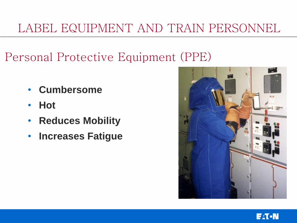
Personal Protective Equipment (PPE)
• Cumbersome
• Hot
• Reduces Mobility
• Increases Fatigue
LABEL EQUIPMENT AND TRAIN PERSONNEL

Personal Protective Equipment (PPE)
Much Better !
LABEL EQUIPMENT AND TRAIN PERSONNEL

SOLUTIONS THAT REDUCE ARC FLASH INJURIES and DAMAGE
• Label Equipment & Train Personnel
• Minimize Risk with Good Safety Practices
• Reduce Available Fault Current
• Faster Clearing Time
• Move People Further Away
• Redirect Blast Energy
• Prevent Fault

•De-Energize Equipment versus “Working It Live”
unless increased hazards exist or infeasible due
to design or operational limitations.
•Switching remotely (if possible)
Closing and tightening door latches or door bolts
before operating a switch.
Standing to the side and away as much as
possible during switching operations.
MINIMIZE RISK WITH GOOD SAFETY PRACTICES

Bad – Exposed Back of Neck Good – All of Body Protected
MINIMIZE RISK WITH GOOD SAFETY PRACTICES

SOLUTIONS THAT REDUCE ARC FLASH INJURIES and DAMAGE
• Label Equipment & Train Personnel
• Minimize Risk with Good Safety Practices
• Reduce Available Fault Current
• Faster Clearing Time
• Move People Further Away
• Redirect Blast Energy
• Prevent Fault

• Lowering fault current
does not always lower
Incident Energy
• Fuse vs Breaker
• No one single answer
• Must Do Arc Flash Study
REDUCE AVAILABLE FAULT CURRENT

• Operate with a Normally Open Tie During
Maintenance
• Change Out Transformer – Smaller KVA and/or
Higher Impedance
• Add Reactors
• May be Better or Worse with Fuses
• BUT– Complications--
REDUCE AVAILABLE FAULT CURRENT

High Resistance Grounding
• HRG Units
• Typically Under 5 Amps
• Pulsing Contactor
• Many Options
• LV or MV
• Does Not Preclude PPE
• Lowers Probability of
Accident
REDUCE AVAILABLE FAULT CURRENT

SOLUTIONS THAT REDUCE ARC FLASH INJURIES and DAMAGE
• Label Equipment & Train Personnel
• Minimize Risk with Good Safety Practices
• Reduce Available Fault Current
• Faster Clearing Time
• Move People Further Away
• Redirect Blast Energy
• Prevent Fault

Issues with IEEE 1584 LV Circuit Breakers
Neither circuit breaker calculation method accounts for
their current-limiting effects.
Neither based on any actual circuit breaker test data.
SIMPLE method is based upon “worst case”
time of 4 manufacturers time/current curves.
VERY conservative!
ALTERNATE method requires manufacturer
specific time/current curve input.
Concerns with ALTERNATE method too because circuit
breaker time/current curves are very conservative in their
instantaneous region.
FASTER CLEARING TIMES

IEEE 1584 Generic Equation
IEEE 1584 Using Time Current
Curve Input
Tested Value
Min Mid Max
225 A MCCB with Thermal-Magnetic Trip Unit
Bolted fault current 3.4 kA 35 kA 100 kA
Inc. Energy via IEEE 1584 Table E.1 Generic (Cal/cm2) N/A
1 1.7 4.7
Inc. Energy via IEEE 1584 & Trip Curve (Cal/cm2) 59.6 1.1 2.3
Measured Incident Energy (Cal/cm2) 0.08 0.1 0.11
1200 A MCCB with Electronic Trip Unit
Bolted fault current 20 kA 35 kA 100 kA
Inc. Energy via IEEE 1584 Table E.1 Generic (Cal/cm2) N/A
1 3.5 9.4
Inc. Energy via IEEE 1584 & Trip Curve (Cal/cm2) 218 3.5 5.8
Measured Incident Energy (Cal/cm2) 1.86 1.2 1.64
Incident Energy at
Bolted Fault Current
1 N/A = Not Applicable because it is
outside the range of the IEEE
1584 Generic Equation
Arc Flash Performance Comparison Molded-Case Circuit Breakers
FASTER CLEARING TIMES

Zone Selectively Interlocked Circuit Breakers provide
significantly lower Arc Flash energy values:
Testing confirms Circuit Breakers (4000A maximum)
require Category 2 PPE (8 cal/cm2) with proper
instantaneous settings
During maintenance it is recommended to temporarily adjust
the Instantaneous and Ground Fault (if available) trip settings
to their lowest value
LV Power Circuit Breakers
Unless a Low Voltage Power Circuit Breaker
operates in the Instantaneous trip mode, the
arc flash energy values will require Category 3
PPE or greater

Zone Selective Interlocking
SD=
0.5S
SD=
0.3S
SD=
0.3S
SD=
0.3S
M1
F1 F2 F3 X
35kA fault current
Without ZSI = 0.5 S:
43.7 Cal/cm2
Greater than Cat. 4 PPE
DANGER!
With ZSI = 0.08 S:
7.0 Cal/cm2
FR Shirt & Pants
Cat. 2 PPE
FASTER CLEARING TIMES

Zone Selective Interlocking - Example
• An Off-Shore Oil Platform in the Gulf of Mexico
Lowered Their Incident Energy Exposure from 85
Calories Down to 12.7 Calories by Retrofitting
Their 480 V Swgr with ZSI.
FASTER CLEARING TIMES

High Speed Clearing Bus Differential 87B
FASTER CLEARING TIMES

Arcflash Reduction Maintenance Switch™
• Door Mounted
Components
• Breaker Mounted
Components
Arcflash Reduction Maintenance Switch
DIGITRIP
Harness
Lockout
Switch
Battery
Indicating
Light
FASTER CLEARING TIMES

An external over-ride switch and circuitry are
connected to a breaker’s trip unit, and is
adjustable between 2.5X - 10X.
When a person wants to perform maintenance,
they close the switch, which automatically over-
rides all of the delay functions, and causes the
breaker to trip without any intentional delay
whenever a fault is detected. Use its lockout
features for normal lockout – tag-out procedures.
FASTER CLEARING TIMES
Arcflash Reduction Maintenance Switch™

Upon completion of the maintenance, the lock is
removed, the switch is manually opened, and all
previous trip unit settings are again re-activated,
without need for recalibration.
FASTER CLEARING TIMES
Arcflash Reduction Maintenance Switch™
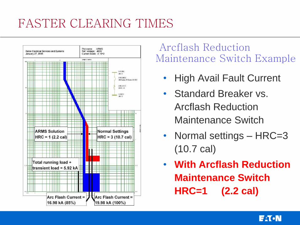
Arcflash Reduction Maintenance Switch Example
• High Avail Fault Current
• Standard Breaker vs.
Arcflash Reduction
Maintenance Switch
• Normal settings – HRC=3
(10.7 cal)
• With Arcflash Reduction
Maintenance Switch
HRC=1 (2.2 cal)
FASTER CLEARING TIMES

Multiple Settings Groups
Similar to LV maintenance switch, only for MV applications
Used to reduce the trip delay of medium-voltage relays while maintenance is being performed on equipment.
Requires relay with multiple settings groups capability
FASTER CLEARING TIMES

• Any Exposure / Racking
Feeder Breakers – Must be
Cleared by Primary Fuse
• 100 Calorie Exposure
FASTER CLEARING TIMES
Substations Without Main Secondaries

Substations Without Main Secondaries
FASTER CLEARING TIMES

Substations Without Main Secondaries
• Retrofill Primary Fuse
with Mini Vac Bkr
• Sense at 480V Txmr-
Trip Primary
• Use Group Settings for
ARMS
• Many Variations
• Must Meet ANSI
C37.59
FASTER CLEARING TIMES

FASTER CLEARING TIMES

FASTER CLEARING TIMES

SOLUTIONS THAT REDUCE ARC FLASH INJURIES and DAMAGE
• Label Equipment & Train Personnel
• Minimize Risk with Good Safety Practices
• Reduce Available Fault Current
• Faster Clearing Time
• Move People Further Away
• Redirect Blast Energy
• Prevent Fault
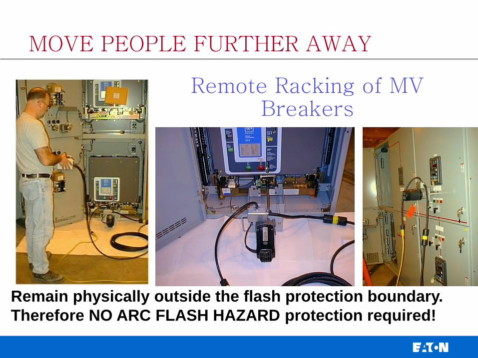
Remote Racking of MV Breakers
Remain physically outside the flash protection boundary.
Therefore NO ARC FLASH HAZARD protection required!
MOVE PEOPLE FURTHER AWAY

VS.
Remote Power Racking
MOVE PEOPLE FURTHER AWAY

Remote Switching: Chicken Switch
• Without • With
MOVE PEOPLE FURTHER AWAY

SOLUTIONS THAT REDUCE ARC FLASH INJURIES and DAMAGE
• Label Equipment & Train Personnel
• Minimize Risk with Good Safety Practices
• Reduce Available Fault Current
• Faster Clearing Time
• Move People Further Away
• Redirect Blast Energy
• Prevent Fault

Arc-Resistant Switchgear
Redirects Arc Energy
and Particulates
REDIRECT BLAST ENERGY

5/15 kV Arc Construction Arc Flaps
2000A or
3000A breaker
with Vent
1200A can be 1
high or 2 high
Control
Section
VT
drawer Manual Close/Open
Push Buttons
MOVE PEOPLE FURTHER AWAY

SOLUTIONS THAT REDUCE ARC FLASH INJURIES and DAMAGE
• Label Equipment & Train Personnel
• Minimize Risk with Good Safety Practices
• Reduce Available Fault Current
• Faster Clearing Time
• Move People Further Away
• Redirect Blast Energy
• Prevent Fault

PREVENT FAULT
Equipment Designed for Safety
Arc Safe MCC Bucket Minimum exposure to energized parts

Bucket Position
Connected
Test
Withdrawn
Handle Mechanism
Device Island
• Start, Stop, Auto, Man
Unit Latch
Breaker
Internal Shutter Position
Open
Closed
Racking Tool Receiver
Starter
PREVENT FAULT

Monitor Transformer Bushings
• Power Factor
• Capacitance
PREVENT FAULT

Monitor Insulation Integrity
• Switchgear , Generators, Motors
PREVENT FAULT

Results of Partial Discharges
Phase to Phase Discharges on Ring Bus - 49 MVA Generator
PREVENT FAULT

Infrared Scanning Windows for LV/MV Assemblies
PREVENT FAULT

Continuous Thermal Monitoring
• Monitoring Connecting
Joints on a PDU, Utilizing
Plastic Bracket System
• Monitoring Individual
Connections
PREVENT FAULT

SOLUTIONS THAT REDUCE ARC FLASH INJURIES and DAMAGE
• Label Equipment & Train Personnel
• Minimize Risk with Good Safety Practices
• Reduce Available Fault Current
• Faster Clearing Time
• Move People Further Away
• Redirect Blast Energy
• Prevent Fault

QUESTIONS ?