innovative optical parametric sources using isotropic semiconductors e. rosencher, m. baudrier, r....
TRANSCRIPT

INNOVATIVE OPTICAL PARAMETRIC SOURCES USING ISOTROPIC
SEMICONDUCTORS
E. Rosencher, M. Baudrier, R. Haidar ,A. Godard, M. Lefebvre and Ph. Kupecek*
ONERA
* University PMC

• Why bother?
• Semiconductor (2) properties
• Quasi-phase matching
• Total internal reflection phase matching
• Random phase matching
• Self-difference frequency generation
• Conclusions
SUMMARY

• Why bother?
• Semiconductor (2) properties
• Quasi-phase matching
• Total internal reflection phase matching
• Random phase matching
• Self-difference frequency generation
• Conclusions

Tunability
Laser Diodes vs
OPO
10
4 5 6 7 8 91
2 3 4 5 6 7 8 910
Laser wavelength (µm)
AlGaN
AlGaAs
InGaAsP
InGaAsSb
InAsSb
PbSSe
PbSnTe
QCL
CRYOGENY
Single diodesingle Pulsed OPO
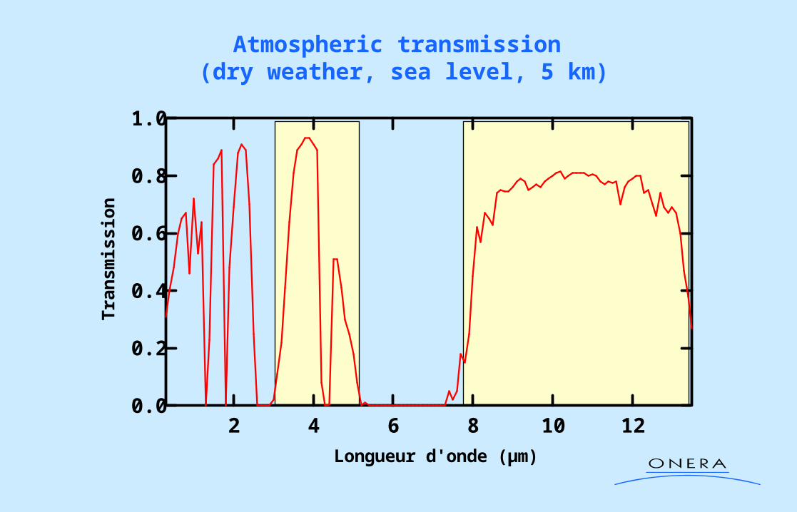
1.0
0.8
0.6
0.4
0.2
0.0
Tran
smis
sio
n
12108642
Longueur d'onde (µm)
Atmospheric transmission (dry weather, sea level, 5 km)
• Why bother?
• Semiconductor (2) properties
• Quasi-phase matching
• Total internal reflection phase matching
• Random phase matching
• Self-difference frequency generation
• Conclusions

SEMICONDUCTORS
• 0.45 µm < cutoff< 20 µm (0.05 eV < Egap < 3 eV)
cutoffE
E
nd
NLOgap
gapP
3
4
3
2
Second Fermi Golden Rule
Harmonic oscillator
• High nonlinear performance (quantum theory of solids) :
• Large transparency region
• Mature technology III-V LiNbO3
4 6 8 10 12 14 16 18 20 2210
20
30
40
50
60
70
(µm)
ZnSe
GaAs
Transmission including Fresnel losses (%)
• Isotropic materials NO possible phase matching scenario
• Low cost
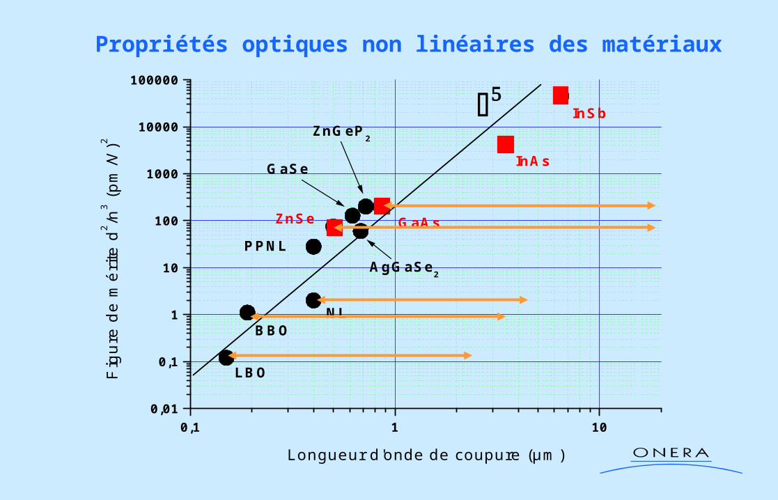
0,1 1 100,01
0,1
1
10
100
1000
10000
100000
AgGaSe2
ZnSe
GaSe
ZnGeP2
GaAs
InAs
InSb
PPNL
NLBBO
LBOFig
ure
de m
érite
d2 /n
3 (pm
/V)2
Longueur d'onde de coupure (µm)
Propriétés optiques non linéaires des matériaux

First order quasi-phase matching
IDFG
k.L
+d +d-d -d
Cohérence
k1
k2
k3
c2

NbLiO3
5000 V
10 kg/cm2
Ferroelectric pollingM. Fejer et al (Standord) Molecular bonding (GaAs, ZnSe)
TRT, ONERA, Stanford
GaAsZnSe…..
Quasi-phase matching techniques
Fresnel birefrigenceR. Haidar et al (ONERA)
Localized growthE. Lallier et al; M. Fejer et al
Ge

Periodical materials breakthrough
2
3
4
5
678
0.1
2
3
Ave
rag
e p
ow
er (
W)
5.04.54.03.53.0
Idler wavelength (µm)
cw
pulsed 20 ns
PPLN
0.01
0.1
1
10
aver
age
po
wer
(W
)
5 6 7 8 91
2 3 4 5 6 7 8 910
2 3 4 5
deff (pm/V)
PPLN
BBO
KTP
POGaAs
2 cm
40 µm f = 10 kHz
20 ns
98% 98%

Precise coherence length (C) determinationexperimental set-up
HgCdTedetector
Filters
Wedge
1.06 µm
1
LiNbO3 OPO
wavelengthcontrol
3 & 2
motorizedtranslation
• Pulse Energy : 1mJ , 15ns
• = 2 cm-1
ZnSe
GaAs
I1 – Fx cos (k.L)
thickness
(a few deg.)
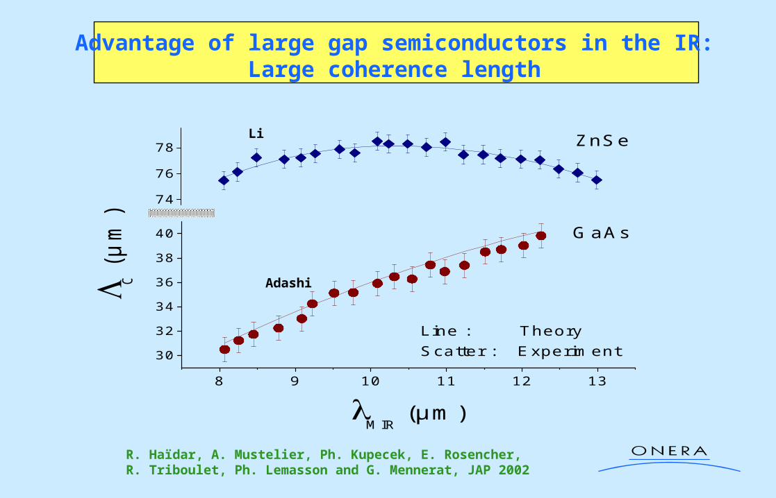
Advantage of large gap semiconductors in the IR:Large coherence length
8 9 10 11 12 13
30
32
34
36
38
40
74
76
78
Line : TheoryScatter : Experiment
ZnSe
GaAs
C (
µm
)
MIR
(µm)
R. Haïdar, A. Mustelier, Ph. Kupecek, E. Rosencher,R. Triboulet, Ph. Lemasson and G. Mennerat, JAP 2002
Adashi
Li

• Why bother?
• Semiconductor (2) properties
• Quasi-phase matching
• Total internal reflection phase matching
• Random phase matching
• Self-difference frequency generation
• Conclusions
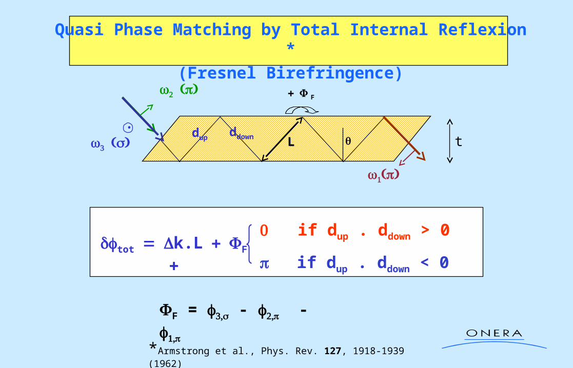
Quasi Phase Matching by Total Internal Reflexion *
(Fresnel Birefringence)
*Armstrong et al., Phys. Rev. 127, 1918-1939 (1962)
tLL
F
dup ddown
•
totk.LF
if dup . ddown > 0
if dup . ddown < 0
F = - -

Angle tuning
totFresnel phase matching
z
I
Optimum thickness
L(2n+1) c Dispersion phase matching
z
I
L
2
2/sin2/sin2
2/2/sin2
tot
tot
NN
LkLk
dfg LNI
Fresnel QPMFresnel QPM

Haïdar et al., APL
.L + 2Fk Fresnel QPMFresnel QPM
N
non resonant QPM
.Lk
3.L
2k
1.L
3k
.Lk
.Lk
0 2
k.L
resonant QPM

Resonant Fresnel angle allowing (1.9 µm, 2.3 µm) 8 µm
Optimum angle for Fresnel birefringence phase matching
20 30 40 50 60 70 80 90 100
-4
-3
-2
-1
0
1
ZnSe
= 28°
F = -
= 45°
F = 0
spp
pss
Limit Angle
F (
rad
ian
s)
Angle (deg)10 20 30 40 50 60 70 80 90 100
-5
-4
-3
-2
-1
0
1
2
= 20°
F = -
= 45°
F = 0
Angle (deg)
F (
rad
ian
s)
GaAs
spp
pss
Limit Angle
Haïdar et al., JOSA B

Fresnel phase matching Configuration :experimental set-up
HgCdTedetector
Filters
1.06 µmLiNbO3 OPO
wavelengthcontrol
3 & 2
• Pulse Energy : 1mJ , 15ns
• = 2 cm-1
1
ZnSe plate
25,5 26,0 26,5 27,0 27,5 28,0 28,5 29,0
0,0
0,2
0,4
0,6
0,8
1,0
DF
G e
ffici
ency
(a.
u.)
Internal Angle (°)
Theory Experiment
R. Haïdar, A. Mustelier, Ph. Kupecek, E. Rosencher,R. Triboulet, Ph. Lemasson, APL 2002
10 mm
10 mm
ZnSe

20 25 30 35 40
0
100
200
300
400
B
A
IR E
nerg
y (p
J)
Internal Angle (°)
Theory Experiment
9 10 11 12 1318
24
30
36
42
An
gle
(°
)
DFG wavelength (µm)
Photonic yield :
MIR Source :.1 µJ between 9 µm and 13 µm
Pump 3 : 150 µJ
2µm2n
µm10n10
phot
phot
9
10
11
12
25 30 35 40 45
t = 832 µmt = 885 µm
ppppspspp
pss
Mid
-IR
Wav
elen
gth
(µm
)
Internal Angle (°)
Fresnel quasi-phase matching: GaAs

0 20 40 60 80
R = 98%
R = 100% Noptimal
Intensity I3
out
Number of bounces N0 20 40 60 80 100 120 140
0
20
40
60
80
100
R = 99.5%
R = 99%
R = 98%
R = 100%
R = 97%
Effi
cien
t b
oun
ces N
eff
Geometrical Bounces N
Limitations of Fresnel QPM: influence of wafer roughness
)(nm)(
(%)R
ZnSe GaAs
11 4
27 45 25 45
98 98.6 99.4 99.6
R1g c
1µm40104
cm1g3

shift x
Nmax 200
Limitation to Fresnel QPM: Goos-Hänchen shift
Equivalent to walk off

• Why bother?
• Semiconductor (2) properties
• Quasi-phase matching
• Total internal reflection phase matching
• Random phase matching
• Self-difference frequency generation
• Conclusions

Few lines of trivial theory
mk
1em23
N1
m
1jjXki
mXkiedEEE *
322Xk222N
1 IINcXdI sin
Very predictive:- conversion yield proportional to sample length- independant on polarisation- resonant for - N/Neff easily measurable and compared with materials
cX
Non depletion approximation
3 processes independant
coh1eff IN
2Xk2
d
deff cNN
2
2 sinwith
nX 1nX
nd
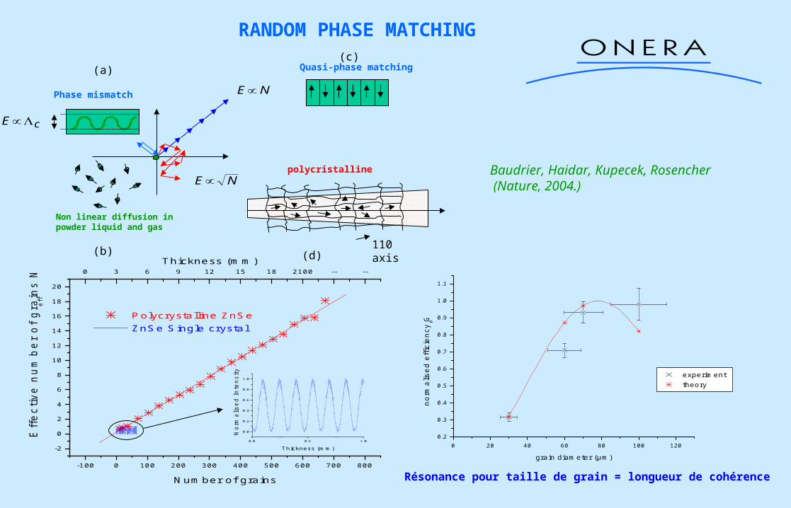
RANDOM PHASE MATCHING
0 20 40 60 80 100 1200.2
0.3
0.4
0.5
0.6
0.7
0.8
0.9
1.0
1.1
norm
alis
ed e
ffic
iency
G 0
grain diameter (µm)
experiment theory
Résonance pour taille de grain = longueur de cohérence
110 axis
NE
NEpolycristalline
Non linear diffusion inpowder liquid and gas
Phase mismatch
cE
(a)
(b)
Quasi-phase matching(c)
(d)
-100 0 100 200 300 400 500 600 700 800
-2
0
2
4
6
8
10
12
14
16
18
20
0 3 6 9 12 15 18 2100 -- --Thickness (mm)
Eff
ective
nu
mb
er
of
gra
ins N
eff
Number of grains
Polycrystalline ZnSe ZnSe Single crystal
0.0 0.5 1.0
0.0
0.2
0.4
0.6
0.8
1.0
No
rma
lise
d I
nte
nsity
Thickness (mm)
Baudrier, Haidar, Kupecek, Rosencher (Nature, 2004.)

• Why bother?
• Semiconductor (2) properties
• Quasi-phase matching
• Total internal reflection phase matching
• Random phase matching
• Self-difference frequency generation
• Conclusions

Cr2+-doped ZnSe
0.510 µm
VB
CB
High optical cross-sectionHigh solubilityLarge bandwith
Good ONL materials
Good lasing materialsSelf OPO
S
T2.1 2.3 µm
Cr2+
1.9 µmPompe: 1.9 µmLaser: 2.3 µmDFG-OPO: 10 µm
ZnSe:Cr X
WiFi collapse !
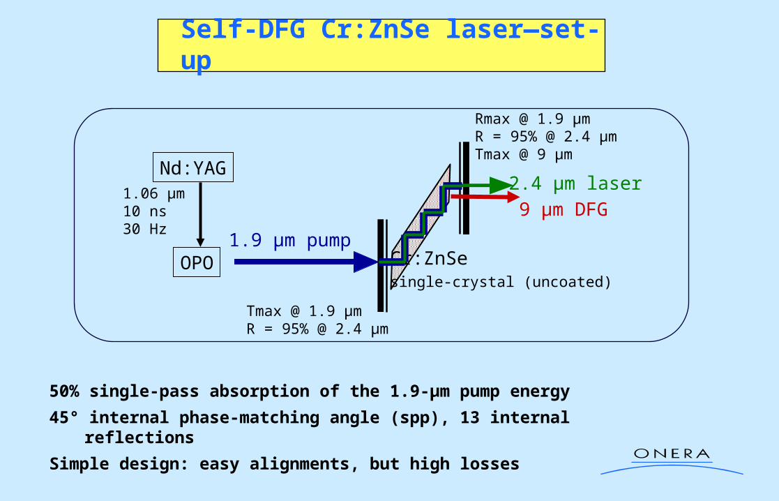
Self-DFG Cr:ZnSe laser—set-up
50% single-pass absorption of the 1.9-µm pump energy
45° internal phase-matching angle (spp), 13 internal reflections
Simple design: easy alignments, but high losses
1.9 µm pump
2.4 µm laser
9 µm DFG
Cr:ZnSesingle-crystal (uncoated)
OPO
Nd:YAG1.06 µm10 ns30 Hz
Tmax @ 1.9 µmR = 95% @ 2.4 µm
Rmax @ 1.9 µmR = 95% @ 2.4 µmTmax @ 9 µm

Laser (2.4 µm)5% yield (/absorbed energy)
Small coupler transmission to maximize the 2.4-µm intracavity electric field
Self-DFG Cr:ZnSe laser – first results
First demonstration of self-DFG in Cr:ZnSe laser
9-µm DFG preliminary resultsNote: thresholdless emission !
0.4 0.6 0.8 1.0 1.2 1.4 1.6
0
5
10
15
20
0.31 0.46 0.61 0.76 0.92 1.07 1.22
Laser energy (2.4µm) Linear fit
Absorbed pump energy (mJ)
Lase
r en
ergy
(µ
J)
Incident pump energy (mJ)
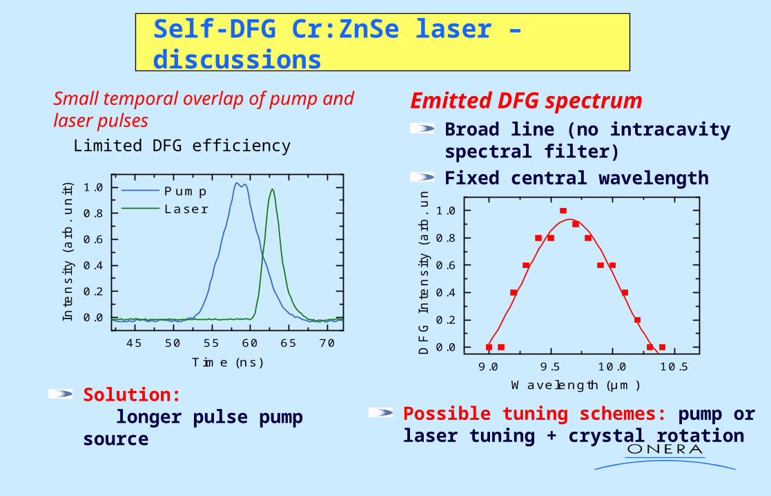
Small temporal overlap of pump and laser pulses Limited DFG efficiency
45 50 55 60 65 70
0.0
0.2
0.4
0.6
0.8
1.0
Inte
nsity (
arb
. u
nit)
Time (ns)
Pump Laser
Solution: longer pulse pump source
Emitted DFG spectrumBroad line (no intracavity spectral filter)
Fixed central wavelength
9.0 9.5 10.0 10.5
0.0
0.2
0.4
0.6
0.8
1.0
DF
G I
nte
nsity (
arb
. u
nit)
Wavelength (µm)
Possible tuning schemes: pump or laser tuning + crystal rotation
Self-DFG Cr:ZnSe laser – discussions

• Why bother?
• Semiconductor (2) properties
• Quasi-phase matching
• Total internal reflection phase matching
• Random phase matching
• Self-difference frequency generation
• Conclusions

Conclusions
• Isotropic semiconductors are becoming viable solutions fornon linear optical sources in the mid-infrared
• Fresnel phase matching allows very large tunability from the mid-IR to the terahertz
•Cr2+ doped ZnSe allows thresholdless self DFG generation
which greatly simplify source architectures: first realisation presented!
•Surface roughness principal limitations to Fresnel QPM
Next step: electrical pumping of OPO !
•Random phase matching works in poly ZnSe and allows very large samples