innovative field cast uhpc joints for precast bridge decks
TRANSCRIPT
Designing and Building with UHPFRC : State of the Art and Development
1
Innovative Field Cast UHPC Joints for Precast Bridge Decks – Design, Prototype Testing and Projects
Vic PERRY, FCSCE, MASc., P. Eng. Vice-President & General Manager – Ductal®Lafarge North America, Inc Calgary, AB, Canada
Gary WEISS, MBA, P.Eng. District Engineer Ministry of Transportation of Ontario, Thunder Bay, ON, Canada
Summary
Bridge owners are frequently faced with the need to replace critical bridge components during strictly limited or overnight road closure periods. This paper presents the development, testing and installation of several projects utilizing precast HPC bridge elements with field cast Ultra-High Performance Concrete (UHPC) Joint Fill. By utilizing UHPC’s unique combination of superior properties in conjunction with precast bridge deck panels, bridge design is advanced. Benefits include: improved bridge deck performance through the reduction of joint size and complexity, improved durability, improved continuity, speed of construction, elimination of post-tensioning and extended usage life.
Keywords: abrasion; composite; ductile; durability; fiber-reinforced; impermeability; UHPC; usage-
life; rapid repair; precast. 1. Introduction
In North America today, there are more than 150,000 bridges that are structurally deficient or obsolete and more than 3000 new bridges are added each year [1]. State, provincial and municipal bridge engineers are seeking new ways to build better bridges, reduce travel times and improve repair techniques; thereby reducing maintenance costs which are diverted from capital budgets required for building much needed new highways and bridges. Bridge owners are frequently faced with the need to replace critical bridge components during strictly limited or overnight road closure periods. One of the largest challenges facing bridge authorities is the long-term durability of bridge decks which receive continuous impact loading from trucks and changing environmental conditions. The years of continuous flexural and thermal stresses create long-term deterioration and maintenance issues for bridge decks. While Cast-In-Place (CIP) concrete decks with High-Performance Concrete (HPC) and corrosion resistant reinforcing can significantly extend the deck life, it creates high user inconvenience and is problematic for bridge deck replacement in high traffic areas. The use of HPC precast deck panels is a common method to speed construction and address the user inconvenience; however the jointing of the precast system is a source of potential maintenance.

UHPFRC 2009 – November 17 th & 18th – Marseille, France
2
The use of Post-Tensioning (P/T) across the joints has been used as a method to ensure the deck effectively remains structurally monolithic while performing under the constant pounding of truck wheel loads and seasonal conditions, more specifically; to ensure the joint does not deteriorate or leak. While post-tensioning can resolve most of the performance issues, it is not without potential problems. It is expensive, it has potential for corrosion and is not practical for slabs with a cross fall. Furthermore, the analysis is complex in terms of the correct post-tensioning forces (# of strands and forces longitudinal vs transverse), creep losses, grout properties, potential long-term corrosion of the strands and sequencing of P/T vs anchoring of the panels to the sub-structure. The introduction of new methodologies and innovative material technologies facilitates the implementation of new solutions. One new technology helping to solve the problem with deteriorating bridges is an ultra-high performance, fiber reinforced cement composite material (“Ductal®”) by Lafarge North America [2] [3], which offers superior technical characteristics including ductility, strength and durability while providing highly moldable products, with a high quality surface aspect and a short bond development length. Ultra-high performance concrete (UHPC), used as a jointing material in conjunction with reinforced high performance concrete (HPC) panels provides a synergistic, new approach for reconstruction of bridge superstructures. In 2004, the Ministry of Transportation of Ontario (MTO) implemented a new solution for replacement of deteriorating highway bridge decks. The solution was to use a precast concrete deck and approach slab panels with Glass Fiber Reinforced Polymer (GFRP) bars in the top mat and curbs. It was the objective of the MTO to expand on the Harryson joint in order to eliminate field formwork and simplify the reinforcing details [6]. Field cast UHPC was used in the infill portions to develop the continuity in the deck panels. The project selected to introduce this new solution was a highway bridge over the Canadian National Railway (CNR) at Rainy Lake, near Fort Frances, Ontario. Since 2004, the MTO has used a similar type of solution for 4 completed bridge deck projects and 10 more are currently in various phases of design or construction. Utilizing the superior characteristics of the material technology enabled the designer to greatly simplify the precast panel fabrication and installation processes. This simplified design provided the owner with improved tolerances, reduced risk, increased speed of construction, an overall cost savings in construction and a more durable, longer lasting bridge deck solution. 2. The Solution
In 2003, the material supplier (Lafarge), consultant (Cook Engineering, Thunderbay, ON, Canada) and owner (MTO) worked together to develop a new, innovative solution for reconstructing old, deteriorated CIP bridge decks that would enable the bridge to remain open to traffic during the retrofit. The concept required the existing reinforced CIP deck to be removed transversely, one-half at a time (while maintaining full traffic volume) and replaced one-lane at a time with a new precast system. The owner required a precast deck joint design that would provide a long-term, low maintenance, durable joint. Additionally, they did not want to use a field post-tensioning system for the precast panel joints because it is expensive, it has potential for corrosion and is not practical for slabs with a cross fall. Furthermore, the analysis for post-tensioning is complex in terms of the correct post-tensioning forces (# of strands and forces; longitudinal vs transverse), creep losses, grout properties, potential long-term corrosion of the strands and sequencing of P/T vs anchoring of the panels to the sub-structure.

Designing and Building with UHPFRC : State of the Art and Development
3
The first joint fill project was the existing “CN Overhead Bridge” [4], originally constructed in 1962 in Ontario, on Highway 11, over the CN rail lines near Rainy Lake. The bridge was designed as a 24.384 meter (80′) single span x 10.972 meters (36′) wide, skewed (Figure 2) with steel plate girders and a 178 mm (7″) thick cast-in-place, reinforced concrete deck with an 80 mm (3″) thick asphalt wear surface (Figure 1). The existing deck had reached its useful life and was in need of major reconstruction. A staged method of construction was utilized to maintain one lane of traffic during deck reconstruction [5].
Fig. 1 Transverse section of existing bridge – CN Overhead at Rainy Lake, ON [4]
Fig. 2 Plan of existing and rehabilitated bridge The new precast deck panels (Figure 3) were rectangular, 225 mm (9″) nominal thickness and 5775 mm x 3600 mm (19′ x 12′) reinforced with GFRP bars (top mat only), each way, top and bottom (conventional steel rebar). The deck panels were manufactured with 35 MPa (5000 psi) concrete. GFRP bars were selected as top slab reinforcing since they do not corrode and provide excellent durability characteristics. Highway bridges are traditionally susceptible to corrosion, primarily from

UHPFRC 2009 – November 17 th & 18th – Marseille, France
4
the top surfaces due to their exposure to deicing salts. The owners decided to provide a non-corrosive reinforcing medium such as GFRP bars. The precast deck panels were designed to be fully composite with the existing steel girders. This was accomplished by providing standard Nelson shear studs welded to the top flanges of the girders at the precast panel pockets, which were subsequently fixed with UHPC. Precast continuity was provided by reinforcing embedment/development with the field cast UHPC construction joints. The higher strength/E-Modulus UHPC joint material also improved the stiffness of the connection between the panels and the Nelson studs, thereby enhancing the composite section between the deck and beams.
Fig. 3 Precast panel layout Traditional closure strips between panels usually involve complex reinforcing arrangements, e.g. looped bars and a large quantity of transverse reinforcement in the joint. To reduce complexity during fabrication and installation of the precast deck panels, a new, simpler joint was developed - based on research conducted at Chalmers University of Technology, Sweden [6]. This study focused on using UHPC in a 100 mm (4″) wide closure strip, without any complicated hooked or bent bars. At the Rainy Lake CNR Overhead, UHPC was selected in order to achieve a much simpler 210 mm (8″) wide joint. To eliminate the need for installing forms on the transverse closure strips, a small concrete lip was fashioned on the bottom part of the panel. During installation, a small strip of Evazote (foam backer rod) was glued to the edge of this lip so that when two panels were butt together, a watertight seal was formed. This eliminated the need for additional forms on the underside of the transverse closure strips (Figure 4). Because of the narrow closure strips, these lips were more robust and durable than traditional configurations. To confirm design assumptions, tensile pullout tests were carried out and it was decided that full bar development could be realized in the field-cast joints, using a bar embedment length of approximately 190 mm (7½″) (Figure 5).

Designing and Building with UHPFRC : State of the Art and Development
5
Fig. 4 Typical transverse field joint
Fig. 5 Section through longitudinal field cast joint In addition to the Rainy Lake Deck panel project, UHPC Joint Fill has been used in several other projects (Figures 6 to 8) in the province of Ontario, Canada as well as NY State, USA (Figure 9).
Fig. 6: Current River Bridge, ON (2007) Fig. 7: Sunshine Creek Bridge, ON (2007) utilized Ductal® Joint Fill for precast curb a single span, side-by-side box girder sections under bridge railings. bridge with Ductal® Joint Fill along the length of the girders.
GFRP Bar 190 mm (7½″) overlap

UHPFRC 2009 – November 17 th & 18th – Marseille, France
6
Fig. 8: Hawk Lake Bridge, ON (2008) Fig. 9: Village of Lyons, NY (2009) Ductal® Joint Fill project with side–by- side-by-side single-bulb-tee girder (8x26) side precast box beams. project. Close- up of a finished joint. In addition to the completed projects, there are other projects utilizing UHPC Joint Fill in design and construction in the province of Ontario and the states of New York, Iowa and South Dakota. 3. Characteristics of the UHPC Jointing Material Technology
The UHPC technology utilized for the joints in this project is an ultra-high-strength, ductile material formulation made with constituent ingredients such as: Portland cement, silica fume, quartz flour, fine silica sand, high-range water reducer, water and steel fibers. The product utilized for this application, Ductal® JS1000, is covered by one of many patents in a range of ultra-high performance concretes, all under trademark (Ductal®). Compressive strengths for bridge applications can range from 120 to 200 MPa (17,400 to 29,000 psi) and flexural strengths range from 15 to 40 MPa (2,200 psi to 5,800 psi). The material’s high mechanical properties are a result of proportioning the constituent ingredients to produce a modified compact grading with a nominal maximum coarse aggregate size of 400 µm, and a fibre geometry of 12 mm x 0.2 mm (½" x 0.08"). The ratio of maximum coarse aggregate size to fibre is important to facilitate random orientation of fibres and a ductile behavior. These performance characteristics result in improved micro-structural properties of the mineral matrix, especially toughness and control of the bond between the matrix and fibre. With a carbonation depth penetration of 0.5 mm (0.02″), there is almost no carbonation or penetration of chlorides or sulphides and a high resistance to acid attack. The superior durability characteristics are due to low porosity from a combination of fine powders, selected for their relative grain size (maximum 0.5 mm [0.02″]) and chemical reactivity. The net effect is a maximum compactness and a small, disconnected pore structure. The following is an example of the range of material characteristics for Ductal® JS1000. [6]
Designing and Building with UHPFRC : State of the Art and Development
7
Strength Durability Compressive (28 days) 140 MPa (20000 psi) Freeze/thaw (after 300 cycles) 100% Compressive (48 hours) 100 MPa (14500 psi) Salt-scaling (loss of residue) <0.10 g/m2 Flexural 30 MPa (4300 psi) Carbonation depth <0.5 mm Young’s Modulus (E) 50 GPa (7200 ksi) The materials are supplied to the site in a three-component premix (pre-blended powders in 35 kg (80 lb) bags plus superplasticizer and fibres), along with a mixer and technical support from the supplier. 4. Testing
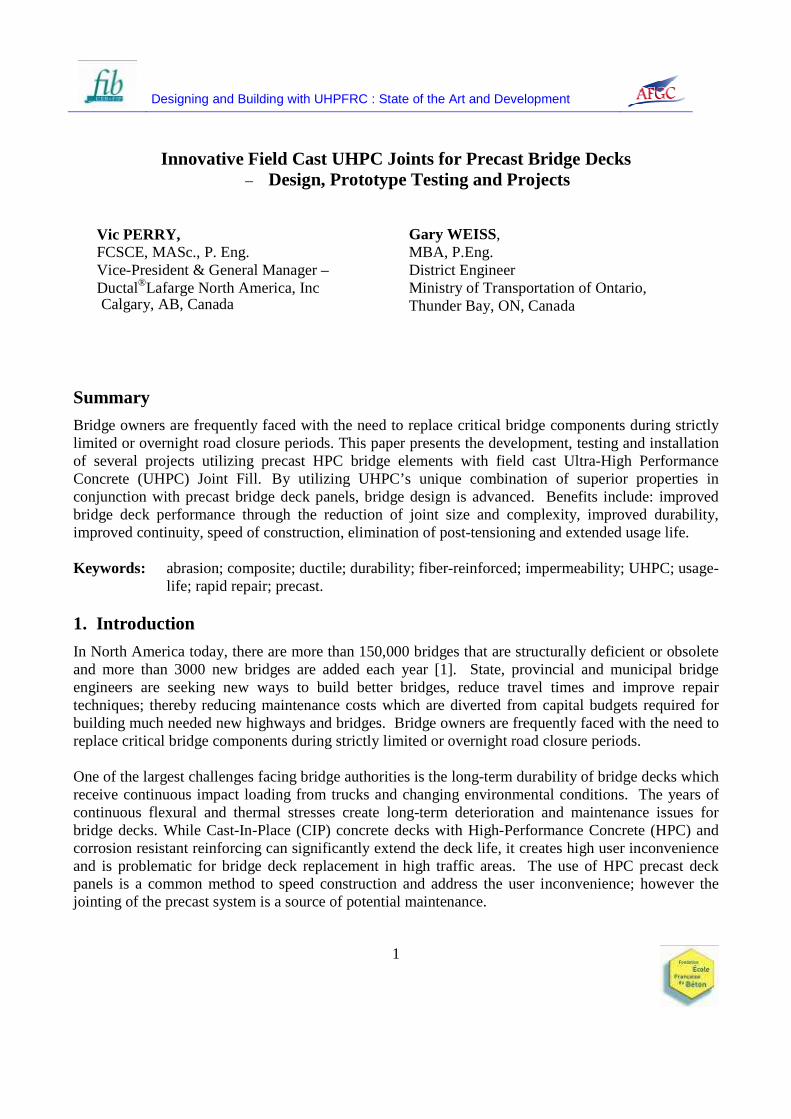
Previous work and various tests have been conducted to demonstrate the pullout capacity of steel strands in UHPC [7], which has shown that significantly shorter bond development lengths are required to fully develop the bars. However, since bond development lengths for GFRP in UHPC had not been tested, a test program was undertaken in the labs of EBA Engineering Consultants Ltd. (Calgary), in order to develop a design recommendation. Single GFRP bars were embedded into UHPC blocks at lengths of 100 mm (4″) and 150 mm (6″) (Figure 10). The bars were loaded to failure, in accordance with Annex B of CAN/CAS-S806-02 [8]. Test results (Table 1) show that the mode of failure for the 150 mm (6″) embedment was a tensile force induced fracture of the GFRP rod, with no discernible slippage nor any detectable UHPC fracturing. For the 100 mm (4″) embedment, the failure was a delamination of the epoxy sand layer to the bar. Both embedment lengths failed in the bond of the epoxy sand coating. The force applied was in excess of the ultimate capacity of an equivalent steel bar. Table 1 Pullout test data – 15 mm GFRP in UHPC Sample # Embedment Length Failure Load (N) Failure Method 1 100 mm (4″) 67,110 GFRP Rod Rupture 2 150 mm (6″) 95,684 GFRP Rod Rupture
This test result validated the design, which allowed for a precast bridge deck with a 210 mm (8″) wide joint compared to a conventional design of a 600 mm (24″) wide joint. This also permitted the use of the CHBDC simplified method of analysis [9].
Fig. 10 Test set-up for pullout capacity of GFRP in UHPC block

UHPFRC 2009 – November 17 th & 18th – Marseille, France
8
Another concern for bridge owners with respect to joints is the ability of the joint to remain water tight during the life of the bridge. In order to simulate wheel impact loading under environmental conditions, test panels were manufactured at the Fort Miller Company, NY and shipped to the US Federal Highway Administration’s (FHWA) Turner-Fairbanks laboratory for fatigue testing in a field simulated, wet condition.
Fig. 11 Bridge deck panels with water ponding under fatigue loading (Courtesy of FHWA) The HPC precast deck panels (Figure 11) with the UHPC Joint fill showed no signs of leakage or degradation at 9 million cycles of a simulated wheel loading (cycling from one ton to 8 tons). 5. Design Considerations for Durability of the Joint
One challenge facing highway authorities when utilizing full depth precast bridge deck panels is durability of the joints due to the constant flexing from truck loadings and corrosion from salt of the rebar crossing the joints. The design of the joints focused on balancing a joint detail that provided deck continuity for loads, minimized traffic disruption, speed of construction and long-term durability. Albeit, testing (Figure 11) shows excellent performance, regardless of the materials used, shrinkage across the joint is a potential problem that may result in a joint interface between the panel and joint fill, which is an area for the ingress of salts. To minimize this corrosion potential, a non-corrosive rebar (GFRP) can be used in the top mat. Additionally, the joint size is minimized to provide the least possible total shrinkage across the joint. Minimizing the joint size also reduced the quantity of jointing material to be cast on-site and simplified the precast panel manufacturing.
Designing and Building with UHPFRC : State of the Art and Development
9
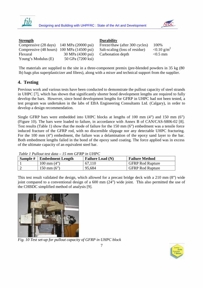
The JS1000 joint fill material has a superior freeze/thaw resistance, extremely low porosity, higher than normal flexural strength and superior toughness, which provides improved resistance to climatic conditions and continuous flexing from truck loadings across the joints. Field casting of monolithic UHPC joints in excess of 25 meters on projects to date has shown no signs of shrinkage, cracking or leaking. The improved durability of GFRP concrete bridge decks has also been shown in a recent study by ISIS Canada [10]. The ISIS study of cores taken from bridge decks, wharf decks and parapets constructed of GFRP in concrete during the periods of 1997 to 2000, showed no signs of deterioration. 6. Construction/Installation
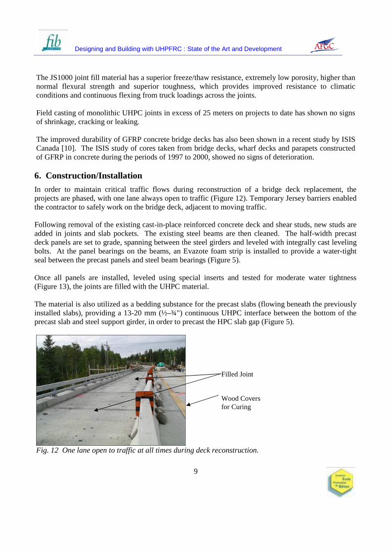
In order to maintain critical traffic flows during reconstruction of a bridge deck replacement, the projects are phased, with one lane always open to traffic (Figure 12). Temporary Jersey barriers enabled the contractor to safely work on the bridge deck, adjacent to moving traffic. Following removal of the existing cast-in-place reinforced concrete deck and shear studs, new studs are added in joints and slab pockets. The existing steel beams are then cleaned. The half-width precast deck panels are set to grade, spanning between the steel girders and leveled with integrally cast leveling bolts. At the panel bearings on the beams, an Evazote foam strip is installed to provide a water-tight seal between the precast panels and steel beam bearings (Figure 5). Once all panels are installed, leveled using special inserts and tested for moderate water tightness (Figure 13), the joints are filled with the UHPC material. The material is also utilized as a bedding substance for the precast slabs (flowing beneath the previously installed slabs), providing a 13-20 mm (½–¾") continuous UHPC interface between the bottom of the precast slab and steel support girder, in order to precast the HPC slab gap (Figure 5).
Fig. 12 One lane open to traffic at all times during deck reconstruction.
Filled Joint Wood Covers for Curing
UHPFRC 2009 – November 17 th & 18th – Marseille, France
10
The face of the precast panels received a roughened surface to enhance bond and water tightness of the joint. Additionally, the surface is saturated surface dry before filling the joints with the UHPC. The design assumption was that there would be a minimal amount of shrinkage across the joint. The use of the GFRP bars and extremely small shrinkage would not negatively impact the durability of the joint. However, fatigue testing under ponding conditions has shown that even after 9 million cycles of wheel loading, the joint does not leak.
The UHPC material is batched on site with an IMER Mortarman 750 Mixer, in 0.2 cubic meter (0.7 cubic foot) batches. Two or more mixers are used in parallel, alternating to provide for batching and placing in a continuous basis. A four-person crew is able to run the mixers and produce 0.5 cubic meters (1.7 cubic yards) per hour. Casting time to complete the filling of all joints for one half of the bridge takes approximately 8 hours.
Fig. 13 Joints ready for filling with UHPC
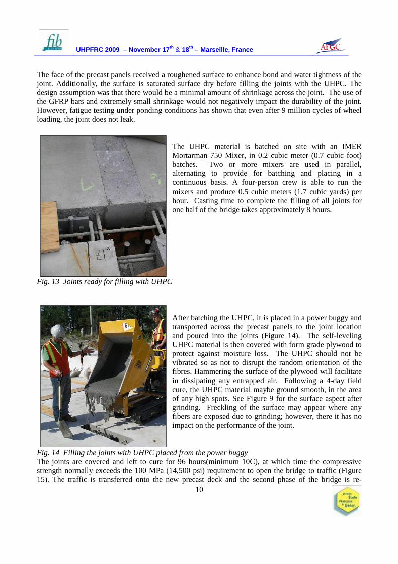
After batching the UHPC, it is placed in a power buggy and transported across the precast panels to the joint location and poured into the joints (Figure 14). The self-leveling UHPC material is then covered with form grade plywood to protect against moisture loss. The UHPC should not be vibrated so as not to disrupt the random orientation of the fibres. Hammering the surface of the plywood will facilitate in dissipating any entrapped air. Following a 4-day field cure, the UHPC material maybe ground smooth, in the area of any high spots. See Figure 9 for the surface aspect after grinding. Freckling of the surface may appear where any fibers are exposed due to grinding; however, there it has no impact on the performance of the joint.
Fig. 14 Filling the joints with UHPC placed from the power buggy The joints are covered and left to cure for 96 hours(minimum 10C), at which time the compressive strength normally exceeds the 100 MPa (14,500 psi) requirement to open the bridge to traffic (Figure 15). The traffic is transferred onto the new precast deck and the second phase of the bridge is re-

Designing and Building with UHPFRC : State of the Art and Development
11
constructed with the same system. A waterproof membrane and asphalt overlay may be placed on the entire new deck surface after the second phase is completed.
During casting of joints, 75 mm x 150 mm (3″ x 6″) cylinders are cast. The cylinders are field cured beside the cast joints then transported to a lab for end grinding and testing. Due to UHPC’s higher strengths, special procedures for cylinder preparation must be followed in order to ensure that test results represent the actual material properties.
Fig. 15 CN Overhead Bridge at Rainy Lake with precast deck panels and UHPC joint fill 7. Conclusion
The UHPC material’s combination of superior properties including strength, durability, fluidity and increased bond capacity, in conjunction with reinforced precast panels, provides engineers with the ability to create new, optimized solutions for bridge construction. By utilizing the combined material properties in this application, precast bridge deck panel design is advanced. Direct benefits include: improved bridge deck performance through the reduction of joint size and complexity; improved continuity and speed of construction and; elimination of field post-tensioning, while indirect benefits include: improved durability; lower maintenance and; extended usage life. The owners analysis has shown that the precast and UHPC field cast joint solution is less expensive than conventional cast-in-place concrete. The projects highlighted and the testing presented validates precast bridge decks with UHPC compared to a conventional designs of CIP or precast with post-tensioned joints. The precast deck panel system with UHPC joints enables bridges to be opened to traffic in 48 hours after the joint pour (closure). While there are still challenges when implementing this solution on a wide scale basis, the real challenge ahead is to identify the optimized shapes for precast deck panels and joints for various deck arrangements. When the optimized configurations are determined, precasters, manufacturers and contractors can invest in the formwork and equipment to economically produce these solutions. The true economics of these systems will eventually bring value to highway users through standard mass production of optimized UHPC shapes and systems and ultimately, years of low maintenance usage.

UHPFRC 2009 – November 17 th & 18th – Marseille, France
12
8. References
[1] BHIDE, S., “Material Usage and Condition of Existing Bridges in the US”, PCA, Skokie, Illinois USA, 2008.
[2] GRAYBEAL, B.A., “Fabrication of an Optimized UHPC Bridge”, PCI National Bridge Conference, Atlanta, GA, USA, 2004.
[3] BIERWAGEN, D, MOORE, B. and PERRY, V., “Revolutionary Concrete Solutions”, Construction Specifier, USA, 2006.
[4] COOK ENGINEERING, “Project Drawings for CN Overhead at Rainy Lake, ON”, Thunderbay, Ontario Canada, 2006.
[5] PERRY, V., SCALZO, P., WEISS, G., “Innovative Field Cast UHPC joints for Precast Deck Panel Bridge Superstructures – CN Overhead Bridge at Rainy Lake, Ontario”, 2007 Concrete Bridge Conference, USA, 2007.
[6] HARRYSON, PETER, “High Performance Joints for Concrete Bridge Applications”, Structural Engineering International, Volume 13, Number 1, 2003.
[7] LAFARGE NORTH AMERICA, Product Data Sheet: Ductal® JS1000, www.imagineductal.com, 2009.
[8] LUBBERS, A. and STEINBERG, E., “Bond of Pre-stressing Strands in UHPC”, International Symposium on High Performance Concrete, USA, 2003.
[9] Canadian Highway Bridge Design Code, CAN/CSA – S6-06, Canada, 2006. [10] MUFTI, A., et al, “Field Study on Durability of GFRP Reinforcement”, International Bridge
Deck Workshop, Winnipeg, Manitoba, Canada, 2005.