innovative clean coal technology (icct)
TRANSCRIPT

INNOVATIVE CLEAN COAL TECHNOLOGY (ICCT)
500 MW DEMONSTRATION OF ADVANCED WALL-FIRED COMBUSTION TECHNIQUES
FOR THE REDUCTION OF NITROGEN OXIDE @Ox) EMISSIONS FROM COAL-FIRED BOILERS
Technical Progress Report Fourth Quarter 1994
DOE Contract Number DE-FC22-90PC8965 1
SCS Contract Number C-91-000027
Prepared by:
Southern Company Services, Inc. P. 0. Box 2625
Birmingham, Alabama 35202

DISCLAIMER
Portions of this document may be illegible in electronic image products. Images are produced from the best available original document.

LEGAL NOTICE
This report was prepared by Southern Company Services, Inc. pursuant to a cooperative agreement partially funded by the U.S. Department of Energy and neither Southern Company Services, Inc. nor any of its subcontractors nor the U.S. Department of Energy, nor any person acting on behalf of either:
Makes any warranty or representation, express or implied with respect to the accuracy, completeness, or usefulness of the information contained in this report, or process disclosed in this report may not infringe privately-owned rights; or
Assumes any liabilities with respect to the use of, or for damages resulting fiom the use of, any information, apparatus, method or process disclosed in this report.
Reference herein to any specific commercial product, process, or service by trade name, trademark, manufacturer, or otherwise, does not necessarily constitute or imply its endorsement, recommendation, or favoring by the U.S. Department of Energy. The views and opinion of authors expressed herein do not necessarily state or reflect those of the U.S. Department of Energy.
.. 11

EXECUTIVE SUMMARY
This quarterly report discusses the technical progress of an Innovative Clean Coal Technology (ICCT) demonstration of advanced wall-fired combustion techniques for the reduction of nitrogen oxide (NOx) emissions from coal-fired boilers. The project is being conducted at Georgia Power Company’s Plant Hammond Unit 4 located near Rome, Georgia. The primary goal of this project is the characterization of the low NOx combustion equipment through the collection and analysis of long-term emissions data. The project provides a stepwise evaluation of the following NOx reduction technologies: Advanced overfire air (AOFA), Low NOx burners (LNB), LNB with AOFA, and Advanced Digital Controls and Optimization Strategies.
The project has completed the baseline, AOFA, LNB, and LNB+AOFA test segments, fulfilling all testing originally proposed to DOE. Analysis of the LNB long-term data collected show the full load NOx emission levels to be near 0.65 1bMBtu. This NOx level represents a 48 percent reduction when compared to the baseline, full load value of 1.24 1bMBtu. These reductions were sustainable over the long-term test period and were consistent over the entire load range. Full load, fly ash LO1 values in the LNB configuration were near 8 percent compared to 5 percent for baseline. Results from the LNB+AOFA phase indicate that full load NOx emissions are approximately 0.40 lb/MBtu with a corresponding fly ash LO1 value of near 8 percent. Although this NOx level represents a 67 percent reduction from baseline levels, a substantial portion of the incremental change in NOx emissions between the LNB and LNB+AOFA configurations was the result of operational changes and not the result of the AOFA system. Phase 4 of the project is now underway. Hammond Unit 4 had a scheduled outage starting October 1 and continuing until October 31. The Unit resumed operation on November 1 and diagnostic, loss-on-ignition, and performance testing was conducted. The purpose of these tests was to determine the emissions and performance characteristics of the unit prior to activation of the advanced controlloptimization strategies. Based on short- and long-term testing to date, full load NOx emissions are approximately 0.44 lb/MBtu and fly ash loss-on-ignition values near 8 percent. The methodology selected for demonstration at Hammond Unit 4 during Phase 4 of the project is the Generic NOx Control Intelligent System (GNOCIS). The core technology is based on an artificial neural network combustion model and includes sensor validation, reconstruction, and conditioning routines. Prototype testing of GNOCIS is being conducted at Alabama Power Company’s Gaston Unit 4 and PowerGen’s Kingsnorth Unit 1 prior to the comprehensive at Hammond 4. Modeling efforts with data collected from Hammond 4 during the LNB+AOFA test phase continues pending collection of Phase 4A data. The version of Pavilion’s Process Insights necessary for a successful demonstration is currently not available, however, a “Beta” release of this s o h a r e has been made available to SCS and other project participants. One of the two on-line carbon-in-ash monitoring systems ordered for Hammond 4 is now operational. The second on-line carbon-in-ash monitoring system is now being manufactured.

TABLE OF CONTENTS
1 . INTRODUCTION ....................................................................................................... 9 2 . PROJECT DESCRTPTION ........................................................................................... 11
2.1. Test Program Methodology .......................................................................... 11 2.2. Unit Description ............................................................................................ 13 2.3. Advanced Overfire Air (AOFA) System ...................................................... 14 2.4. Low NOx Burners ......................................................................................... 14 2.5. Application of Advanced Digital Control Methodologies ............................ 15
3 . PROJECT STATUS .................................................................................................... 17 3.1. Project Summary ........................................................................................... 17 3.2. Current Quarter Actmties ............................................................................ 17 3.3 Phase 4A Testing .......................................................................................... 18
3.3.1. Diagnostic Testing ......................................................................... 18 3.3.2. Performance Testing ...................................................................... 28 3.3.3. Long-Term Generation and Emissions .......................................... 44
3.4. On-Line Carbon-in-Ash Monitors ................................................................ 44 3.5. Advanced Low NOx Digital Controls System .............................................. 45
3.5.1. Digital Control System .................................................................. 46 3.5.2. Advanced Controls and Optimization ............................................ 46
4 . FUTURE PLANS ........................................................................................................ 48 5 . ACKNOWLEDGMENTS ........................................................................................... 49
. . .
BIBLIOGRAPHY
iv
LIST OF TABLES
Table 1: Work Breakdown Structure ................................................................................. 11 Table 2: Inputs to Data Acquisition System ...................................................................... 13 Table 3: Phase 4 Milestones / Status .................................................................................. 17 Table 4: Phase 4A Diagnostic Tests (to date) .................................................................... 19 Table 5: NOx Sensitivity to Excess O2 .............................................................................. 23 Table 6: Performance Tests Summary ............................................................................... 29 Table 7: Mill Performance ................................................................................................. 31 Table 8: Pulverizer Airmuel Ratios ................................................................................... 31 Table 9: Pulverizer Fuel Flows 32 Table 10: Burner Fuel Flows ............................................................................................. 32 Table 11: Burner Dirty Air Velocities ............................................................................... 33 Table 12: Combustion Air Flows ............................ :. ......................................................... 38 Table 13: Phase 4A Performance Tests Coals ................................................................... 44 Table 14: Future Plans ....................................................................................................... 48
I ..........................................................................................
V

LIST OF FIGURES
Figure 1 : Plant Hammond Unit 4 Boiler ............................................................................ 12 Figure 2: Advanced Overfire Air System .......................................................................... 16 Figure 3: Low NOx Burner Installed at Plant Hammond .................................................. 16 Figure 4: Excess O2 Levels Tested ................................................................................... 20 Figure 5: NOx vs . Load ..................................................................................................... 21 Figure 6: Comparison of Phase 3B and 4A NOx vs . Load ................................................ 21 Figure 7: 480 MW Excess O2 Characteristics ................................................................... 22 Figure 8: NOx vs . Excess O2 . 400 MW ........................................................................... 22 Figure 9: NOx vs . Excess O2 . 300 MW ........................................................................... 23 Figure 10: CO vs . NOx Tradeoff . 480 MW ...................................................................... 25 Figure 1 1 : CO vs . NOx Tradeoff . 400 MW ...................................................................... 25 Figure 12: CO vs . NOx Tradeoff . 300 MW ...................................................................... 26 Figure 13: Fly Ash Loss-on-Ignition vs . Excess O2 at 480 MW ...................................... 26 Figure 14: Fly Ash Loss-on-Ignition vs . Overfire Air Flow at 480 MW .......................... 27 Figure 15: NO, and LO1 Variation with Excess O2 Variations ........................................ 27 Figure 16: NO, and LO1 Variation with OFA Flow Variations ........................................ 28 Figure 17: Burner Locations .............................................................................................. 30 Figure 18: Measured Mill Fineness ................................................................................... 30 Figure 19: Measured Coal Flows by Mill and Coal Pipe ................................................... 34 Figure 20: Deviation of Coal Pipe Coal from Mill Average Flow .................................... 34 Figure 2 1 : Measured Dirty Air Velocity by Mill and Coal Pipe ....................................... 35 Figure 22: Deviation of Coal Pipe Dirty Air Velocity from Mill Average ........................ 35 Figure 23: Indicated vs . Measured Overfire Air Flows . Northeast Quadrant ................... 38 Figure 24: Indicated vs . Measured Overfire Air Flows . Northwest Quadrant ................. 39 Figure 25: Indicated vs . Measured OverfI1.e Air Flows . Southeast Quadrant ................... 39 Figure 26: Indicated vs . Measured Overfire Air Flows . Southwest Quadrant ................. 40 Figure 27: Actual vs . Indicated Overfire Flow .................................................................. 40 Figure 28: Error in Overfire Air Flow ............................................................................... 41 Figure 29: Comparison of Phase 3B and 4A Overfire Air Flow Rates .............................. 41 Figure 30: Performance Tests NO, Emissions . All Phases .............................................. 43 Figure 3 1 : Performance Tests Fly Ash Loss-on-Ignition . All Phases .............................. 43
vi

TABLE OF ABBREVIATIONS
acfm AMIS AOFA ASME C CfWA) CEM CFSF Cl co DAS DCS DOE ECEM EPA EPRI ETEC F FC FWEC Flame GPC H HHV HVT ICCT KPPH
LNB LO1
MOOS MW N NOx NSPS
OFA PA
PTC
W )
(M)Btu
090,
Psig
actual cubic feet per minute All mills in service Advanced Overfire Air American Society of Mechanical Engineers carbon Clean Air Act (Amendments) Continuous emissions monitor Controlled Flow/Split Flame chlorine carbon moNOxide data acquisition system digital control system United States Department of Energy extractive continuous emissions monitor Environmental Protection Agency Electric Power Research Institute Energy Technology Consultants Fahrenheit fixed carbon Foster Wheeler Energy Corporation Flame Refractories Georgia Power Company hydrogen higher heating value High velocity thermocouple Innovative Clean Coal Technology kilo pounds per hour POunW low NOx burner loss on ignition (million) British thermal unit Mills out of service megawatt nitrogen nitrogen oxides New Source Performance Standards oxygen overfire air primary air pounds per square inch gauge Performance Test Codes
vii

RSD S scs scs so2 S O R I Spectrum THC UARG VM
TABLE OF ABBREVIATIONS (continued)
relative standard deviation sulfur specific collection area Southern Company Services sulfur dioxide Southern Research Institute Spectrum Systems Inc. total hydrocarbons Utility Air Regulatory Group volatile matter
... Vlll

1. INTRODUCTION This document discusses the technical progress of a U. S. Department of Energy (DOE) Innovative Clean Coal Technology (ICCT) Project demonstrating advanced wall-fired combustion techniques for the reduction of nitrogen oxide @Ox) emissions from coal- fired boilers. The project is being conducted at Georgia Power Company's Plant Hammond Unit 4 (500 MW) near Rome, Georgia. The project is being managed by Southern Company Services, Inc. (SCS) on behalf of the project co-funders: The Southern Company, the U. S. Department of Energy (DOE), and the Electric Power Research Institute. In addition to SCS, The Southern Company includes five electric operating companies: Alabama Power, Georgia Power, Gulf Power, Mississippi Power, and Savannah Electric and Power. SCS provides engineering, research, and financial services to The Southern Company. The Clean Coal Technology Program is a jointly funded effort between government and industry to move the most promising advanced coal-based technologies from the research and development stage to the commercial marketplace. The Clean Coal effort sponsors projects which are different from traditional research and development programs sponsored by the DOE. Traditional projects focus on long range, high risk, high payoff technologies with the DOE providing the majority of the funding. In contrast, the goal of the Clean Coal Program is to demonstrate commercially feasible, advanced coal-based technologies which have already reached the "proof of concept" stage. As a result, the Clean Coal Projects are jointly funded endeavors between the government and the private sector which are conducted as Cooperative Agreements in which the industrial participant contributes at least fifty percent of the total project cost. The primary objective of the Plant Hammond demonstration is to determine the long-term effects of commercially available wall-fired low NOx combustion technologies on NOx emissions and boiler performance. Short-term tests of each technology are also being performed to provide engineering information about emissions and performance trends. A target of achieving fifty percent NOx reduction using combustion modifications has been established for the project. Specifically, the objectives of the projects are:
1. Demonstrate in a logical stepwise fashion the short-term NOx reduction capabilities of the following advanced low NOx combustion technologies:
a. Advanced overfire air (AOFA) b. Low NOx burners (LNEI) c. LNB with AOFA d. Advanced Digital Controls and Optimization Strategies
2. Determine the dynamic, long-term emissions characteristics of each of these combustion NOx reduction methods using sophisticated statistical techniques.
9

3. Evaluate the progressive cost effectiveness @e., dollars per ton NOx removed) of the low NOx combustion techniques tested.
4. Determine the effects on other combustion parameters (e.g., CO production, carbon carryover, particulate characteristics) of applying the NOx reduction methods listed above.

2. PROJECT DESCRIPTION 2.1. Test Program Methodology In order to accomplish the project objectives, a Statement of Work (SOW) was developed which included the Work Breakdown Structure (WBS) found in Table 1. The WBS is designed around a chronological flow of the project. The chronology requires design, construction, and operation activities in each of the first three phases following project award.
Table 1: Work Breakdown Structure Phase I Task
1.1 1.2 1.3 1.4 1.5
2.1 2.2 2.3
3.1 3.2
2 2
3 3 " 5.2
* Indicates change fton
Date Description Phase 0 Pre-Award Negotiations Phase 1 Baseline Characterization Project Management and Reporting 8/89 - 4/90 Site Preparation 8/89 - 10189 Flow Modeling 9/89 - 6/90 Instrumentation 9/89 - 10189 Baseline Testing 11/89 - 4/90 Phase 2 Advanced Overfire Air Retrofit Project Management and Reporting 4/90 - 3/91 AOFA Design and Retrofit 4/90 - 5/90 AOFA Testing 6/90 - 3/91 Phase 3 Low NOx Burner Retrofit Project Management and Reporting LNB Design and Retrofit LNB Testing with and without AOFA Advanced Low NOx Digital Control System*
3/91 - 8/93* 4/91 - 5/91 5/91 - 8/93* 8/93 - 9/95*
Final Reporting and Disposition
Disposition of Hardware 12/95* original work breakdown structure.
Project Management and Reporting 9/95 - 12/95*
The stepwise approach to evaluating the NOx control technologies requires that three plant outages be used to successively install: (1) the test instrumentation, (2) the AOFA system, and (3) the LNBs. These outages were scheduled to coincide with existing plant maintenance outages in the fall of 1989, spring of 1990, and spring of 1991. The planned retrofit progression has allowed for an evaluation of the AOFA system while operating with the existing pre-retrofit burners. As shown in Figures 1, the AOFA air supply is separately ducted fkom the existing forced draft secondary air system. Backpressure dampers are provided on the secondary air ducts to allow for the introduction of greater quantities of higher pressure overfire air into the boiler. The burners are designed to be plug-in replacements for the existing circular burners.
11

Flow M e a s u r e m e n t 7 1
Backpressure Dampers
Superheaters Acoustic
- Reheater
Economizer
- ,-Test Ports
I )F Flue Gas to
AOFA Ports
) Air Preheater
Instrument Combustion Air I I Room
f Low Automated Data Collection System . Continuous Emission Monitor
Boundary Burners . Acoustic Pyrometer . Heat Flux Transducers Air Ports . Control Room Data
Coal Feed Pipes
Figure I: Plant Hammond Unit 4 Boiler
The data acquisition system (DAS) for the Hammond Unit 4 ICCT project is a custom designed microcomputer based system used to collect, format, calculate, store, and transmit data derived from power plant mechanical, thermal, and fluid processes. The extensive process data selected for input to the DAS has in common a relationship with either boiler performance or boiler exhaust gas properties. This system includes a continuous emissions monitoring system (NOx, SO2, 02, THC, CO) with a multi-point flue gas sampling and conditioning system, an acoustic pyrometry and thermal mapping system, furnace tube heat flux transducers, and boiler efficiency instrumentation. The instrumentation system is designed to provide data collection flexibility to meet the schedule and needs of the various testing efforts throughout the demonstration program. A summary of the type of data collected is shown in Table 2. During each test phase, a series of four groups of tests are conducted. These are: (1) diagnostic, (2) performance, (3) long-term, and (4) verification. The diagnostic, performance, and verification tests consist of short-term data collection during carefully established operating conditions. The diagnostic tests are designed to map the effects of changes in boiler operation on NOx emissions. The performance tests evaluate a more comprehensive set of boiler and combustion performance indicators. The results from these tests will include particulate characteristics, boiler efficiency, and boiler outlet emissions. Mill performance and air flow distribution are also tested. The verification tests are performed following the end of the long-term testing period and serve to identify any potential changes in plant operating conditions.
12

1 Table 2: Inputs to Data Acquisition System I
Boiler Drum Pressure Superheat Outlet Pressure Cold Reheat Pressure Barometric Pressure Reheat Spray Flow
Feedwater Flow Secondary Air Flows
Main Steam Temperature Hot Reheat Temperature
Desuperheater Outlet Temp. Economizer Outlet Temp.
Air Heater Air Outlet Temp. BFP Discharge Temperature
Stack NOx Stack 0 2
Generation
Hot Reheat Pressure Superheat Spray Flow
Main Steam Flow Coal Flows
Primary Air Flows Cold Reheat Temperature Feedwater Temperature
Desuperheater Inlet Temp. Air Heater Air Inlet Temp.
Ambient Temperature Relative Humidity
Stack SO2 Stack Opacity
Overfive Air Flows
As stated previously, the primary objective of the demonstration is to collect long-term, statistically significant quantities of data under normal operating conditions with and without the various NOx reduction technologies. Earlier demonstrations of emissions control technologies have relied solely on data from a matrix of carefully established short-term (one to four hour) tests. However, boilers are not typically operated in this manner, considering plant equipment inconsistencies and economic dispatch strategies. Therefore, statistical analysis methods for long-term data are available that can be used to determine the achievable emissions limit or projected emission tonnage of an emissions control technology. These analysis methods have been developed over the past fifteen years by the Control Technology Committee of the Utility Air Regulatory Group (UARG). Because the uncertainty in the analysis methods is reduced with increasing data set size, UARG recommends that acceptable 30 day rolling averages can be achieved with data sets of at least 51 days with each day containing at least 18 valid hourly averages. 2.2. Unit Description Georgia Power Company's Plant Hammond Unit 4 is a Foster Wheeler Energy Corporation (FWEC) opposed wall-fired boiler, rated at 500 MW gross, with design steam conditions of 2500 psig and 1000/1000"F superheatheheat temperatures, respectively. The unit was placed into commercial operation on December 14, 1970. Prior to the LNB retrofit, six FWEC Planetary Roller and Table type mills provided pulverized eastern bituminous coal (12,900 Btu/lb, 33% VM, 53% FC, 1.7% S, 1.4% N) to 24 pre-NSPS, Intervane burners. During the LNB outage, the existing burners were replaced with FWEC Control Flow/Split Flame burners. The unit was also retrofit with six Babcock and Wilcox MPS 75 mills during the course of the demonstration (two each during the spring 1991, spring 1992, and fall 1993 outages). The burners are arranged in a matrix of 12 burners (4W x 3H) on opposing walls with each mill supplying coal to 4
13
burners per elevation. As part of this demonstration project, the unit was retrofit with an Advanced Overfire Air System, to be described later. The unit is equipped with a coldside ESP and utilizes two regenerative secondary air preheaters and two regenerative primary air heaters. The unit was designed for pressurized furnace operation but was converted to balanced draft operation in 1977. The unit, equipped with a Bailey pneumatic boiler control system during the baseline, AOFA, LNB, and LNB+AOFA phases of the project, was retrofit with a Foxboro I/A distributed digital control system for Phase 4 of the project.
2.3. Generally, combustion NOx reduction techniques attempt to stage the introduction of oxygen into the furnace. This staging reduces NOx production by creating a delay in fuel and air mixing that lowers combustion temperatures. The staging also reduces the quantity of oxygen available to the fuel-bound nitrogen. Typical overfire air (OFA) systems accomplish this staging by diverting 10 to 20 percent of the total combustion air to ports located above the primary combustion zone. AOFA improves this concept by introducing the OFA through separate ductwork with more control and accurate measurement of the AOFA airflow, thereby providing the capability of improved mixing (Figure 2).
Foster Wheeler Energy Corporation (FWEC) was competitively selected to design, fabricate, and install the advanced overfire air system and the opposed-wall, low NOx burners described below. The FWEC design diverts air fiom the secondary air ductwork and incorporates four flow control dampers at the corners of the overfire air windbox and four overfie air ports on both the front and rear furnace walls. Due to budgetary and physical constraints, FWEC designed an AOFA system more suitable to the project and unit than that originally proposed. Six air ports per wall were proposed instead of the as- installed configuration of four per wall. 2.4. Low NOx Burners
Advanced Overfire Air (AOFA) System
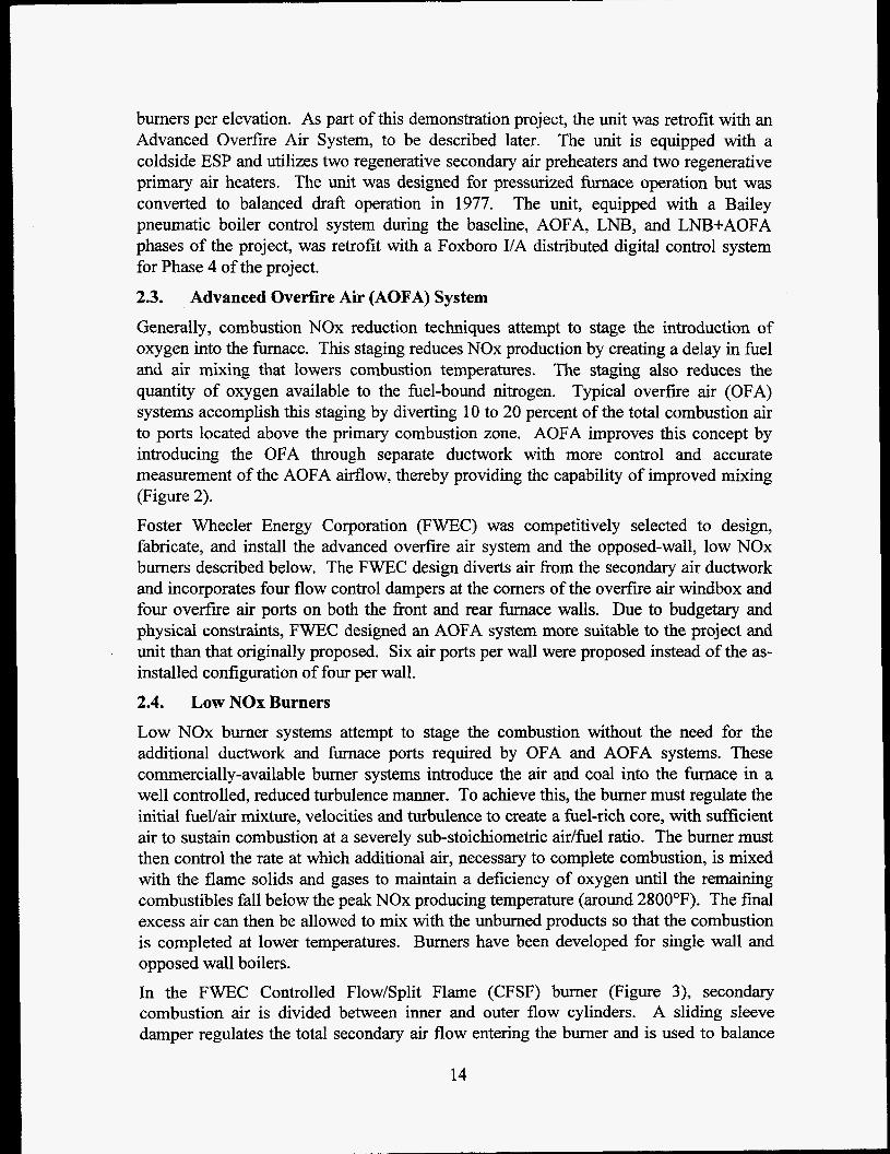
Low NOx burner systems attempt to stage the combustion without the need for the additional ductwork and furnace ports required by OFA and AOFA systems. These commercially-available burner systems introduce the air and coal into the furnace in a well controlled, reduced turbulence manner. To achieve this, the burner must regulate the initial fuellair mixture, velocities and turbulence to create a fuel-rich core, with sufficient air to sustain combustion at a severely sub-stoichiometric aidfuel ratio. The burner must then control the rate at which additional air, necessary to complete combustion, is mixed with the flame solids and gases to maintain a deficiency of oxygen until the remaining combustibles fall below the peak NOx producing temperature (around 2800°F). The final excess air can then be allowed to mix with the unburned products so that the combustion is completed at lower temperatures. Burners have been developed for single wall and opposed wall boilers. In the FWEC Controlled Flow/Split Flame (CFSF) burner (Figure 3), secondary combustion air is divided between inner and outer flow cylinders. A sliding sleeve damper regulates the total secondary air flow entering the burner and is used to balance
14

the burner air flow distribution. An adjustable outer register assembly divides the burners secondary air into two concentric paths and also imparts some swirl to the air streams. The secondary air which traverses the inner path, flows across an adjustable inner register assembly that, by providing a variable pressure drop, apportions the flow between the inner and outer flow paths. The inner register also controls the degree of additional swirl imparted to the coaYair mixture in the near throat region. The outer air flow enters the furnace axially, providing the remaining air necessary to complete combustion. An axially movable inner sleeve tip provides a means for varying the primary air velocity while maintaining a constant primary flow. The split flame nozzle segregates the coal/air mixture into four concentrated streams, each of which forms an individual flame when entering the furnace. This segregation minimizes mixing between the coal and the primary air, assisting in the staged combustion process. The adjustments to the sleeve dampers, inner registers, outer registers, and tip position are made during the burner optimization process and thereafter remain fixed unless changes in plant operation or equipment condition dictate further adjustments.
2.5. The objective of Phase 4 of the project is to implement and evaluate an advanced digital control/optimization system for use with the combustion NOx abatement technologies installed on Plant Hammond Unit 4. The advanced system will be customized to minimize NOx production while simultaneously maintaining and/or improving boiler performance and safety margins. This project will provide documented effectiveness of an advanced digital control /optimization strategy on NOx emissions and guidelines for retrofitting boiler combustion controls for NOx emission reduction. The methodology selected for demonstration at Hammond Unit 4 during Phase 4 of the project is the Generic NOx Control Intelligent System (GNOCIS).
Application of Advanced Digital Control Methodologies
15

- Partition Plates and Secondary Air Duct Pressure Control Dampers
Secondary Air Duct
Figure 2: Advanced Overfire Air System
Perforated Plate Air Hood l! l
e Sleeve / /
&yT. "/ I ll:m,l 'h Split Flame Coal Nozzle
Figure 3: Low NOx Burner Installed at Plant Hammond
16

3. PROJECT STATUS 3.1. Project Summary
Baseline, AOFA, LNB, and LNB+AOFA test phases have been completed. Details of the testing conducted each phase can be found in the following reports:
0
Phase 1 Baseline Tests Report [ 11,
Phase 2 AOFA Tests Report [2], 0 Phase 3A Low NOx Burner Tests Report [3], and
0 Phase 3B Low NOx Burner plus AOFA Tests Report [4].
Chemical emissions testing was also conducted as part of the project and the results have been previously reported [5]. Phase 4 of the project -- evaluation of advanced low NOx digital controls / optimization strategies as applied to NOx abatement -- is now in progress. A list of the current activities and their current status can be found in Table 3.
Table 3: Phase 4 Milestones / Status ~~ ~~ ~~~
Milestone status Digital control system design, configuration, and installation Completed Digital control system startup Completed Instrumentation upgrades In Progress Advanced controls/optimization design In Progress Characterization of the unit pre- activation of advanced strategies In Progress
...................................................................................................................................................................................................................................
...................................................................................................................................................................................................................................
...................................................................................................................................................................................................................................
...................................................................................................................................................................................................................................
Characterization of the post- activation of advanced strategies 6/95 - 9/95 I
3.2. Current Quarter Activities Hammond Unit 4 had a scheduled outage starting October 1 and continuing until October 31. The unit resumed operation on November 1 and diagnostic, loss-on- ignition, and performance testing was conducted. The purpose of these tests was to determine the emissions and performance characteristics of the unit prior to activation of the advanced controlloptimization strategies. Based on short- and long-term testing to date, full load NOx emissions are approximately 0.44 1bMBtu and fly ash loss-on- ignition values of near 8 percent. One of the two on-line carbon-in-ash monitoring systems ordered for Hammond 4 is now operational. This system, manufactured by Clyde-Sturdevant, samples from two locations at the economizer outlet and will be utilized in the closed-loop optimization strategies under development. The second on-line carbon-in-ash monitoring system, a CAMRAC Corporation CAM unit, is now being manufactured. The delivery of the CAMRAC system, originally scheduled for shipment during November 1994, has been delayed until January 1995 due to the unavailability of a critical component of the assembly. The CAM system will sample from a single location at the precipitator inlet.
17

Installation of the digital control system (DCS) installed during this outage and as part of this project has been completed and the system is operational. All control loops have been tuned and are in automatic. Drawings for the DCS installation are now being finalized and instruction manuals are being prepared.
Design of the advanced controls/optimization portion of the project is continuing. The methodology selected for demonstration at Hammond Unit 4 is the Generic NOx Control Intelligent System (GNOCIS) whose development is being funded by a consortium consisting of the Electric Power Research Institute, PowerGen, The Southern Company, U.K. Department of Trade and Industry, and U.S. Department of Energy. The core technology is based on an artificial neural network combustion model and includes sensor validation, reconstruction, and conditioning routines. Prototype testing of GNOCIS is being conducted at Alabama Power Company’s Gaston Unit 4 and PowerGen’s Kingsnorth Unit 1 prior to the comprehensive at Hammond 4. Pavilion Technologies’ Process Insights is the core software utilized in GNOCIS. Modeling efforts with data collected from Hammond 4 during the LNB+AOFA test phase continues. Long-term data collected from Phase 4A will be used, when available, to create the final combustion models. The version of Process Insights necessary for a successful demonstration is currently not available, however, a “Beta” release of this software has been made available to SCS and other project participants. A Wall-FiredGNOCIS joint project review meeting was held December 8 through 9, 1994 at SCS offices in Birmingham. All project participants were represented at the meeting. 3.3. Phase 4A Testing
Diagnostic and performance tests were conducted fiom November 2 through November 18, 1994. To date, 51 diagnostic tests and 5 performance tests have been conducted during Phase 4A. 3.3.1. Diagnostic Testing The emphasis of diagnostic testing is to determine the combustion characteristics of the unit. The initial Phase 4A diagnostic tests were begun on August 5, 1994 and completed on August 8, 1994. Additional diagnostic tests were conducted fiom November 2, 1994 to November 18, 1994. As discussed earlier, there was a one month unit outage between the August and November tests. In total, there were eleven days of testing comprising 51 various excess oxygen, mill pattern, overfire air flow rate, mill biasing, and loads. Because historic load profiles indicated much greater operating times at 400 MW and above, diagnostic testing was done more extensively at the higher loads. A summary of the diagnostic tests is presented in Table 4.
18

I (Table 4: Phase 4A Diagnostic Tests (As of December 31,1994) Test Date Test Load MOOS OFA 0 2 CO NOx No. Condition Pattern Flow Dry Dry
MW KPPH (%) (%) IblMBtu 129-1 5-Aug-94 HI-LOAD NORMAL 0 2 486 AMlS 664 3.0 38 0.454 129-2 5-Aug-94 HI-LOAD LOW 02 483 AMlS 648 2.7 177 0.399 129-3 5-Aug-94 HI-LOAD HIGH 02 483 AMlS 665 3.9 7 0.533
132-1 BAug-94 HI-LOAD LOW 02 482 AMlS 650 2.9 118 0.440 132-2 Mug-94 HI-LOAD NORM 02 484 AMlS 658 3.5 16 0.498 132-3 8-Aug-94 HI-LOAD HIGH 02 479 AMlS 666 4.1 15 0.556 132-4 BAug-94 HI-LOAD FUEL BIASED TO UPPER MILLS 476 AMlS 613 4.1 16 0.573 132-5 8-Aug-94 HI-LOAD FUEL BIASED TO UPPER MILLS I 479 AMlS 596 3.4 18 0.500
I I 135-1 I 9-Nov-94 I HIGH LOAD, AMIS, NOMINAL 02 I 481 [ AMlS I 606 I 3.4 I 28 I 0.390 135-2 I 9-Nov-94 I HIGH LOAD, AMIS, LOW 02 I 482 I AMlS I 653 I 2.9 I 315 I 0.352 135-3 I 9-Nov-94 I HIGH LOAD, AMIS. HIGH 02 I 479 I AMlS I 675 I 3.9 1 14 I 0.426
136-1 10-Nov-94 HIGH LOAD, NOM 02, BALANCED MILLS 478 AMlS 582 4.0 14 0.449 136-2 10-Nov-94 HIGH LOAD, NOM 02, COAL BIASED HIGH 478 AMlS 595 4.1 17 0.448 136-3 10-Nov-94 HIGH LOAD, NOM 02, COAL BIASED LOW 479 AMlS 597 4.0 13 0.448 136-4 10-Nov-94 HIGH LOAD, NOM 02. BALANCED MILLS 480 AMlS 606 4.1 15 0.449
137-1 11-Nov-94 HIGH LOAD, NOM 02, BAL MILLS, NOM OFA 478 AMlS 636 3.9 18 0.432 137-2 11-Nov-94 HIGH LOAD, NOM 02, BAL MILLS, HIGH OFA 481 AMlS 872 4.1 56 0.413 137-3 11-Nov-94 HIGH LOAD, NOM 02, BAL MILLS, MID OFA 480 AMlS 515 3.8 15 0.438 137-4 11-Nov-94 HIGH LOAD, NOM 02, BAL MILLS, LOW OFA 480 AMlS 268 4.1 8 0.506
I
19

As shown in Figure 4, excess O2 levels were exercised well above and below the design excess O2 levels yielding variations in NOx emissions (Figure 5) from approximately 0.35 to 0.57 lb/MBtu at full load (480 MW) and 0.33 to 0.46 lb/MBtu at the low intermediate load (300 MW). As shown in Figure 6, NO, emissions for the Phase 4A diagnostic tests were similar to the long-term emission levels observed during Phase 3B, with the Phase 4A emissions generally within the 90 percentile range of the emissions observed during Phase 3B.
Based on the O2 variations, the NOx vs. O2 gradient was determined for each of the three loads tested. As can be seen in Figure 7, at 480 MW, NOx emissions were highly dependent on excess O2 and, apparently, to a great extent, a linear function of excess 0, over the range tested (R2 G 0.98). Also, NOx emissions prior to the October outage were approximately 0.1 lb/MBtu greater than those observed following the outage for the same excess O2 and load conditions. The cause for this discrepancy is unknown at this time. Similar NOx vs. O2 gradients and the change in NOx emissions between the pre- and post- October outage were also observed at 400 MW and 300 MW load levels (Figures 8 and 9). Generally, the NOx vs. O2 sensitivity decreased with load (Table 5).
8.0
6.0
P P N" 0 4.0 m m 3 G
2.0
0.0
...... +... - .....
4 Mills --..*
$-- - - - I - - - - -_ .___ 4 ~ . - .~ .~ ........ ... - - ........ -. ........ .- - .... - - - _ - _ _ - .- i s
5 Mills *. _ _ 6 Mills - - - - - - _ . _____ &-- f
Normal Operating Excess 02 a l ? .
0 100 200 300 400 500 600
Load, M W
Figure 4: Excess O2 Levels Tested

4
4 Normal 02 Settings - 4 A
0 100 200 300 400 500 600
Load, MW I
Figure 5: NOx vs. Load
0.70
0.60
a 0.50
I G E x" p 0.40
0.3(
Phase 38 / LNB+AOFA I Long-Term
Phase 4A / LNB+AOFA / Short-Term T \
h 4 - - -- 4
A A l l
0 100 200 300 400 500 600
Load, MW
Figure 6: Comparison of Phase 3B and 4A NOx vs. Load
21

0.70
0.60
2 0.50 m 5 e
0.40
0.30
0.20
- - . ._ - . . - - - . . - y = 0.1067~ + 0.1284
R2 = 0.9776 2 Prior to October 1994 outage
Following October 1994 outage Y / l u
2.0 3.0 4.0 5.0 6.0 7.0
Excess 02, Percent
Figure 7: 480 MW Excess O2 Characteristics
0.70
0.60
2 0.50 m e n
0.30
0.20
Post-Outage E-MOOS l44-4,5,6.7
X PrsCutage B-MOOS 530-12,3,4
- +&*OutageE-MOOS x33-5.6 ._ -_ __-__ A Post-Outage B-MOOS 533-12.3.4
2.0 3.0 4.0 5.0 6.0 7.0
Excess 02, Percent
Figure 8: NOx vs. Excess O2 - 400 M W 22

0'70
1 0.60
0.50
. _ ~ -
+Post-Outage ?44-12,3
0.20 J 2.0 3.0 4.0 5.0 6.0 7.0
6ccess 02, Percent
Figure 9: NOx vs. Excess O2 - 300 M W
Table 5: NOx Sensitivity to Excess O2
Phase 4A Preliminary Diagnostic Tests November 1994
Nominal NOx R' Load Sensitivity*
MW (lb/MBtu)/(% 0,)
480 0.0834 0.98
400 0.0613" 0.78
3 00 0.058 0.99
Prior Phases NOX Sensitivity#**
(Ib/MBtu)/(% 0,)
Phase
-0.08
-0.08 -0.14 -0.04 -0.06
*Based on short-term diagnostic tests.
"E Mill out of service. See phase topical reports for a discussion on the uncertainty of these results. #
23

For comparison, the sensitivities determined from prior phases of the project are also shown in Table 5. As can be seen, sensitivities varied greatly from phase-to-phase for a given load. The explanation for the variation is unknown at this time, however, a contributing factor is likely the relative (as compared to Phase 4A) non-repeatability of the short-term tests during prior phases (Phases 1, 2, 3A, and 3B) and the resultant influence of this non-repeatability on sensitivity determination. For the testing conducted during Phase 4A, NOx emission characteristics were much repeatable than what had been observed in prior phases. The improvement in repeatability can be attributed largely to the improvement of unit stability as the result of the installation of the DCS. A thorough discussion of the difficulties in repeating experiments has been previously reported [ 1, 2,
CO Emissions
As experienced during prior phases, CO emissions were relatively low -- generally below 50 ppm -- at recommended excess O2 levels. At full load, as excess 0, levels were reduced, CO emission levels rose producing the familiar “knee” in emissions (Figure 10). A similar CO vs. 0, characteristic was evident in the 400 MW tests (Figure 11). At the 300 MW load, excess O2 was not reduced sufficiently to generate increased CO emissions (Figure 12).
Fly Ash Loss-on-Iynitios
The results of the LO1 vs. 0, and overfire air flow can be found in Figures 13 and 14, respectively. Similar to what was seen during the Phase 3A NOx vs. LO1 tests, LO1 is highly dependent on excess O2 with sensitivities on the order of 3 percent change in LO1 for every 1 percent change in oxygen [4]. The sensitivity of LO1 with overfire air flow rate was much less than for excess 0, with a change of LO1 of approximately 1.5 percent over the entire usable range of overfire air flow.
NOx vs. LO1 NOx emissions generally increase with increased excess O2 whereas LO1 levels generally decrease thereby producing a conflict of goals; i.e. to reduce both NOx and LOI. As can be seen in Figure 15, using excess O2 alone, NOx emissions could be reduced to below 0.40 lb/MBtu while maintaining LO1 below 8 percent. If NO, levels of 0.45 lb/MBtu were acceptable, LO1 could potentially be reduced to near 6 percent. The range of excess O2 represented by the solid line is approximately 1 percent. It should be stressed that this is a parametric plot where both NO, and LO1 are dependent variables. Similarly, Figure 16 shows the relation of NO, to LO1 for variations in overfire air flow. As with variations of excess O,, a change in overfire air flow which reduces NO, emissions increases LOI.
3,43.
24

500
400
300
200
100
0 2.0
\ CO Emissions vs. Excess 02 480 MW 02 Variations Aug &. Nov 1994
... .... ...... - ~~~ ~ .. . . . . . . .. . . . .. . . .. . . . . . . . .. . . . -
2.5 3.0 3.5 4.0
Excess 02, Percent
4.5 5.0
Figure 10: CO vs. Excess O2 - 480 MW
500
400
300
200
100
0 2.0
~
CO Emissions vs. Excess 02 400 MW 0 2 Variations Aug & Nov 1994
2.5 3.0 3.5 4.0
Excess 02, Percent
4.5 5.0
Figure 11: CO vs. Excess O2 - 400 M W
25

500
400
300
6 200
100
0
CO Errksions vs. Excess 02 300 W 0 2 Variations Aug & Nov 1994
- - - - - - - .- -
4.0 4.5 5.0 5.5 6.0
Excess 02, Percent
6.5 7.0
Figure 12: CO vs. Excess O2 - 300 MW
12
10
6 4
4
i
LO1 vs. Excess 02 480 NMI 02 Variations Aug & Nov 1994
W = 0.8012
2.0 2.5 3.0 3.5 4.0
Excess 02, Percent
4.5 5.0
Figure 13: Fly Ash Loss-on-Ignition vs. Excess O2 at 480 MW
26

10
8
6
4
2
~
Unconpensated
Y Conpensated to 4 R?rcent &cess 02
y = 0.0027~ +6.1602
LO1 vs. OFA flow 480 W OFA Variations Aug & Nov 1994
0 100 200 300 400 500 600 700 800 900
OFA Flow, klblhr
Figure 14: Fly Ash Loss-on-Ignition vs. Overfire Air Flow at 480 M W
0.60
0.50
0.40
0.30
0.20 0
Nox vs. LO1 480 Mw 02 Variations Nov 1994
x
5 10 15
LOI, Percent
20
~~
Figure 15: NO, and LO1 Variation with Excess O2 Variations
27

0.60
0.50
a
- b 0.40 J
5
P 0.30
0.20 0
Nox vs. LO1 480 tvT& OFAVariations Nov 1994
- - - - _.. - A . - - _ _
5 10 15
LOI, Percent
20
Figure 16: NO, and LO1 Variation with OFA Flow Variations
3.3.2. Performance Testing Performance testing was conducted from November 12 through November 16, 1995. As in prior phases of the project, performance tests were used (1) to establish baseline evaluation criteria for retrofits, (2) to quantify boiler characteristics for comparison with other phases of the program, and (3) for comparison with the results of the diagnostic trends. For each performance configuration (10- to 12- hour test day), the following types of data were obtained:
Gaseous emission measurements of NO,, 02, and CO, each composed of at least 10 one-minute sample distribution manifold composite flue gas measurements,
Two ASME PTC 4.1 boiler efficiency determinations, Isokinetic fly ash capture at the ESP inlet, and Inlet fuel and air measurements (primary air distribution, secondary air distribution, coal particle size, and coal flow in each coal pipe).
The performance tests for Phase 4A differed from those previously conducted for this project in that (1) fly ash resistivity, (2) flue gas SO,, and (3) furnace temperature profiles were not evaluated and coal pipe measurements were only conducted at full-load. Five performance tests were conducted at nominal loads of 520,400, 300, and 180 MW. At each nominal load, the coal firing rate was kept as constant as possible and generation
0
0
28

allowed to swing slightly as affected by coal, boiler ash deposits, turbine cycle, and ambient variations. The coal feed rate to all in-service mills was kept as nearly equal as possible based upon digital control system readings. For each performance tests, the desired test conditions were established and allowed to stabilize at least one hour prior to commencement of testing. Normal primary aidfuel ratios and mill outlet temperatures were maintained to the extent possible. A summary of the performance tests can be found in Table 6.
Table 6: Performance Tests Summary
11/13/94
11/13/94
11/15/95
Load M w
400
300
180
520
520
Pattern
None 79 1
None 186
DAS 02
3.5
NOx lbM3tu
0.38
0.34
.33
.43
.45
co PPm
49
51
9
61
46
8.1 7.1
3.6 3.3
8.2 7.2
As in prior project phases, combustion performance tests were performed at each performance test load level (except as noted above) to document the specific performance parameters related to the fuel and combustion systems. Pulverizer Performance The air flow to each mill and the particle size and mass flow distributions of coal to each burner were measured. Specific determinations were: 0 Coal fineness as percentage passing 50, 100 and 200 U.S. Standard Sieve
0
0
0
0
designations, Dirty air flow and distribution between burner lines as observed by dirty air traverse, Fuel flow and distribution between burner lines as observed by isokinetic sample, Pulverizer air to fuel ratios, Primary air flow, as measured at the pulverizer inlet, and Temperature and static pressure of the fuel and air mixture in each burner line.
Coal samples for coal fineness, fuel flow and fuel distribution were collected utilizing an isokinetic coal sampler. Plant Hammond laboratory personnel performed coal sieving for fineness analysis. For reference, the layout of the burners and the mills which supply them is shown in Figure 17. Coal fineness was ascertained during tests 141 and 142 conducted at 520 MW. Isokinetic coal samples were not collected for fineness analysis during tests at 180 MW, 300 MW or 400 MW since mill performance is generally poorest at higher mill loadings. Coal fineness was observed to be at or above typical levels. Coal fineness ranged from 73 percent to 80 percent passing 200 mesh with 0.1 percent or less remaining on 50 mesh. Table 7 and Figure 18 summarizes the results of these analysis.
29

MILL F
MILL A
MILL B
REAR WALL FRONT WALL
OVERFIRE AIR PORTS
0000 OFA-R1 OFA-R2 OFA-R3 OFA-R4
BURNERS
0 0 LOWER FURNACE AIR PORTS
MILL C
MILL D
MILL E
OVERFIRE AIR PORTS
9000 OFA-F1 OFA-F2 OFA-F3 OFA-F4
BURNERS
0 0 LOWER FURNACE AIR PORTS
Figure 17: Burner Locations
s- cn ii 0 0 N
75% --
70% ..
65% -.
60% +
Remaining on 50 Mesh
-+
0.9%
0.8% Y c
0.7%
0.6% $. cn
0.5%
0.4% rn
0.30/0 'a
0
0 In c c .- s
0.2% p1:
0.1%
0.0% 4A 4B 4 c 4D 4E 4F
Mill
Figure 18: Measured Mill Fineness
30

Table 7: Mill Performance Pulverizer Test 141 Test 142
%Passing 200 Mesh % Rem. on 50 %Passing 200 Mesh % Rem. on 50 Mesh Mesh . . . - -. . I
A 74.48% 0.10% 73.69% 0.10% B 77.38% 0.04% 80.03% 0.09% C 73.30% 0.11% 76.49% 0.07% D 76.76% 0.03% 76.73% 0.02% ~ ~
E I 73.48% I 0.05% I 75.41 % I 0.05% F 74.87% 0.12% 76.58% 0.11%
Pulverizer air to he1 ratios were calculated by two methods. The first method calculates air to fuel ratio utilizing the fuel flow observed by the isokinetic sampler and measured dirty air flow. The second method utilizes readings obtained fkom the digital control system and primary air flow observed at the pulverizer inlet. Pulverizer air to fuel ratio observed by isokinetic sample ranged from 1.86 to 2.31 pounds of air per pound of coal. Pulverizer air to fuel ratio using primary air measured at the pulverizer inlet and feeder fuel flow ranged fkom 2.14 to 2.6 pounds of air per pound of coal. Table 8 summarizes the air to fuel ratios.
Table 8: Pulverizer Airmuel Ratios Test Number I 141 I 142
IF Mill Air/Fuel Ratio (M. PNFeeder) I 2.17 I 2.14 I
Pulverizer fuel flows (Table 9) observed by isokinetic sampling were 3 to 25 percent higher than fuel flow indicated by the feeders. This variation is not untypical. Generally, fuel and air balance between each pulverizer’s burner lines was very good by industry standards (Tables 10 and 11). Fuel imbalance between the burners exceeded 10 percent of the mean during both tests on 4A pulverizer and during one of the two tests on 4C and 4F pulverizers. Dirty air velocities were within 5 percent of the mean on all pulverizers except for 4F pulverizer, which was only slightly beyond 5 percent. The results of these tests are summarized in Figures 19 through 22.
31

Table 9: Pulverizer Fuel Flows Test No. 141 Test No. 142
Mill Measured Feeder Fuel % Deviation Measured Feeder Fuel % Deviation
............................................... A Mill 76,264 ..................................................... 64,974 +17.38% ..... ~ 78,853 ............ , ...... .......................... 63,229 ................... +24.71% ~ .......... Fuel Flow Flow Fuel Flow Flow
B Mill 69,496 65,276 +6.46% 69,811 67,607 +3.26% .............................................. ......................... ....... ~ .................. ...................................................... .............................. C Mill 78,975 66,192 +19.31% 73,366 67,310 +9.00% D Mill 72,193 65,208 +10.71% 73,935 63,485 +16.46% E Mill 78,998 64,597 +22.29% 77,485 63,61 I +21.81%
+ I 0.1 0% F Mill 70,795 66,141 +7.04% 70,708 64,223 Total 446,721 392,388 444,158 389,465
.............................................. .......................... .......................... ........................ ~ ........................... .................................
.............................................. ......................... .......................... .......................... ..... ~ .................... ..._ ...........................
.................... .......................... ......................... .......................... ......................... ......................... ............................. .
............................................... .......................... .......................... ......................... .......................... .............. ................
ITable 10: Burner Fuel Flows Test 141 Test 142
Burner Line Fuel Flow %Deviation Fuel Flow %Deviation from Mean from Mean
4A-A 16,415 -13.90% 20,821 +5.62% 4A-B 20,070 +5.27% 23,244 +17.91% 4A-C 22,753 +19.34% 19,165 -2.78% 4A-D 17,026 -10.70% 15,623 -20.75% 46-A 16,995 -2.18% 18,892 +8.25% 4B-B 16,052 -7.61% 16,824 -3.60% 46-c 18,991 +9.31% 16,073 -7.91% 46-D 17,458 +0.48% 18,023 +3.27% 4C-A 21,243 +7.59% 18,000 -1.86% 4C-B 18,690 -5.34% 17,731 -3.33% 4c-c 21,815 +10.49% 18,751 +2.23% 4C-D 17,228 -12.74% 18,884 +2.96% 40-A 19,431 +7.66% 17,831 -3.53% 40-8 16,658 -7.70% 17,629 -4.63% 4DC 16,533 -8.40% 18,028 -2.47% 4D-D 19,571 +8.44% 20,448 +10.63% 4E-A 19,875 +0.64% 18,138 -6.37% 4E-B 20,215 +2.36% 20,527 +5.96% 4E-C 19,331 -2.12% 19,183 -0.97% 4E-D 19,576 -0.88% 19,638 +I .38% 4F-A 17,445 -1.43% 17,340 -1.92% 4F-8 18,764 +6.02% 17,343 -1.90% 4F-C 14,925 -15.67% 16,566 -6.30% 4F-D 19.661 +11.09% 19.469 +10.12%
32

ITable 11: Burner Dirty Air Velocities Test 141 Test 142
Burner Line Dirty Air %Deviation Dirty Air %Deviation Velocity from Mean Velocity from Mean
4A-A 6,005 -1.70% 5,689 -3.68% 4A-B 6,172 +1.03% 5,883 -0.39% 4A-C 6,016 -1.52% 5,925 +0.32% 4A-D 6,243 +2.19% 6,128 +3.75% 4B-A 6,129 -3.78% 6,108 -2.90% 4B-B 6,313 -0.89% 6,093 -3.14% 4B-C 6,430 +0.95% 6,358 +1.07% 4B-D 6,607 +3.72% 6,603 +4.97% 4C-A 6,239 -1.16% 6,381 +0.17% 4C-B 6,293 -0.30% 6,424 +0.85% 4C-C 6,279 -0.52% 6,249 -1.90% 4C-D 6,437 + I .98% 6,426 +0.88% 4D-A 6,103 -0.23% 6,586 -1.20% 4D-B 6,056 -1 .OO% 6,471 -2.92% 4D-C 6,114 -0.05% 6,786 +I .80% 4D-D 6,195 +1.28% 6,820 +2.31% 4E-A 6,891 +0.70% 6,844 -0.41 % 4E-B 6,775 -1 .OO% 7,153 +4.09% 4E-C 6,800 -0.63% 6,632 -3.49% 4E-D 6,907 +0.93% 6,859 -0.19% 4F-A 6,542 +5.98% 6,394 +6.44% 4F-B 5,663 -8.26% 5,790 -3.62% 4F-C 6,340 +2.71% 6,053 +0.76% 4F-D 6.147 -0.42% 5.792 -3.58%
33

L E P
0 Ti m 0 0
-
25000
T-- Coal PiDe 7 I W C B \ A
20000
15000
10000
5000
0 4A 48 4c 4D 4E 4F
Mill
Figure 19: Measured Coal Flows by Mill and Coal Pipe
C m 2 E t 0
C 0 m 5
.-
.c) .- 8
2
Y S 0 e
20%
15%
10%
5%
0%
-5%
-1 0%
-1 5%
-20%
P ,--- Coal Pipe
4A 48 4c 4D 4E 4F Mill
Figure 20: Deviation of Coal Pipe Coal from Mill Average Flow
34

i? 6
7000
6000
5000
4000
3000
2000
1000
0 4A 4B 4c 4D
Mill
4E 4F
Figure 21: Measured Dirty Air Velocity by Mill and Coal Pipe
C m ;
CI C a E n
8%
A 6%
4%
2%
0%
-2%
4%
-6%
-8% I I 4A 48 4c 4D 4E 4F
Mill
Figure 22: Deviation of Coal Pipe Dirty Air Velocity from Mill Average
35

Air Flow Measurement
Unit air flow was measured at the following locations: Secondary air at east(A) and west (B) side main air venturi.
Total airflow leaving each of the air preheaters was measured at this location. Airflow measured at this location includes airflow to the burners and to the advanced overfire ports. Each venturi was traversed on an equal area measurement grid consisting of (48) traverse points (4 ports-12 points per port) by a three-hole Fecheimer probe. Secondary airflow was measured on all performance tests (Tests 138, 139, 140,141 and 142).
Primary air at the pulverizer inlets. Primary airflow entering the pulverizer inlet (under the pulverizer’s grinding table) was measured at this location. Airflow measured at this location includes combined tempering air from the forced draft fans and hot primary air from the primary air preheater. The point of measurement for primary air is prior to introduction of seal air flow. Due to this fact, primary airflow measured at this location will be lower than total airflow observed in the fuel lines. Inlet ducting of each pulverizer was traversed on an equal grid of (40) traverse points (10 ports - 4 points per port) by a standard 90” Pitot Tube. Primary airflow to each operating pulverizer was measured during all performance tests. Dirty airflow at the fie1 lines Dirty airflow was measured in each of the pulverizers four fuel lines. The total dirty airflow measured in each pulverizer’s four fuel lines includes primary airflow (tempering and hot) and seal airflow to the pulverizer and coal feeders. Dirty airflow was measured on an equal area grid of (24) points (2 ports - 12 points per port) by a dirty air probe. Dirty air traverses were conducted to quanti@ pulverizer airflow and to establish isokinetic sampling rate for collection of coal samples. Dirty airflow was measured during performance tests at 520 MW (Tests 141 and 142) and Test 138 at 400 MW. The dirty air probe was also utilized to quanti@ airflow through each pulverizer that was off- line during performance tests at 300 MW and 180 MW. OverJre airflow Overfire airflow was measured in each of the four corners of the advanced overfire air windbox downstream of each louver damper assembly. Overfire airflow in each corner was traversed on an equal grid of (24) points (4 ports4 points per port) by a three-hole Fecheimer probe. Overfire airflow was measured on all performance tests except for the test at 180 MW (Test 140). During test 140 at 180 MW, duct velocities were between 0 and 80 fpm and air flow at these velocities cannot be accurately measured using typical instrumentation. Very low duct velocities were also observed on other performance tests making repeatable and accurate test data difficult to obtain. Due to low duct velocities, a Microtector with l/lOOO”w.c. resolution was required to measure the lower than typical velocities.
36

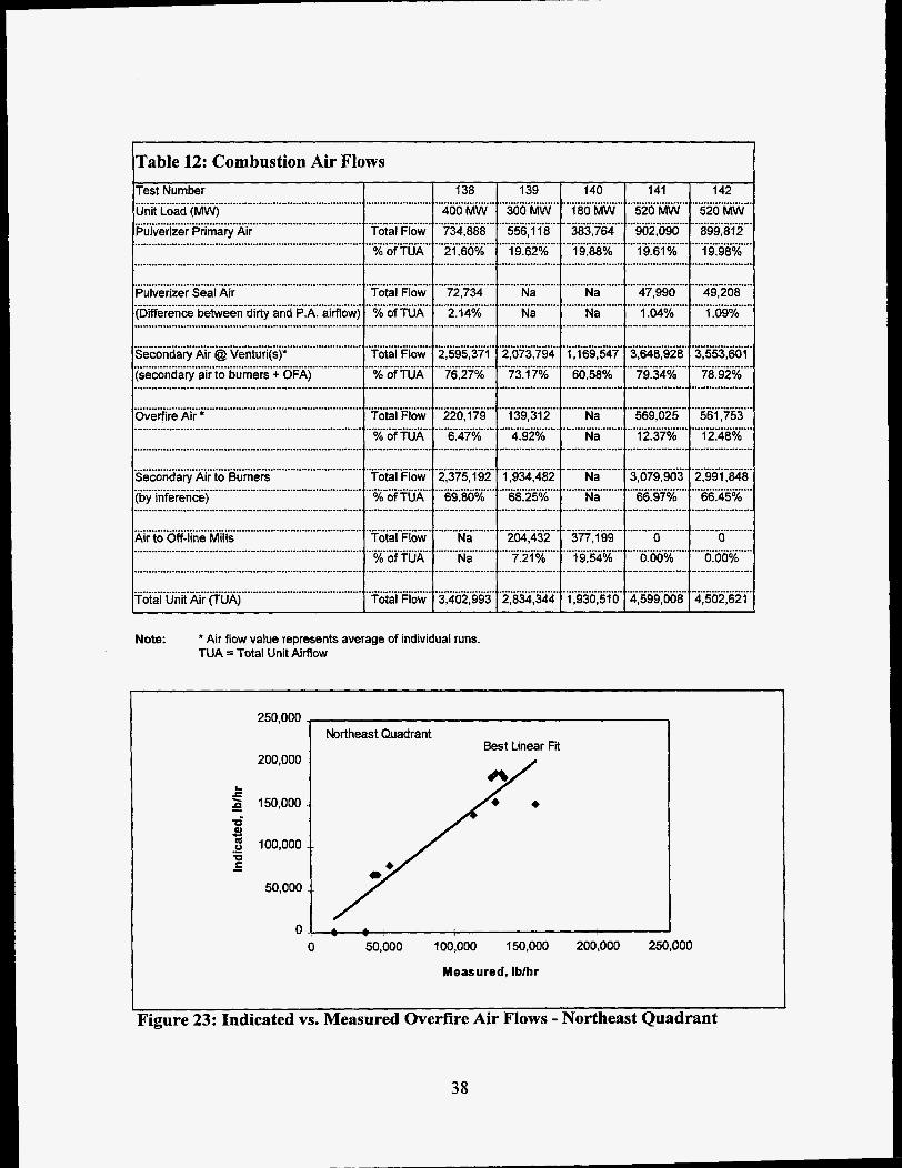
Total unit airflow was calculated by addition of air flow measured at the main air venturi(s), total primary air flow, seal air to the pulverizers and air flow to off-line pulverizers when applicable. Seal air to the pulverizer was ascertained by inference between dirty air flow measured in the fuel lines (which is inclusive of seal air flow) and primary air flow measured at the pulverizer inlet. Dirty air flow from the pulverizers was not measured during tests conducted at 300 MW and 180 MW. Seal air to the pulverizers is not accounted for in total unit air flow during these tests. Table 12 summarizes the total unit airflow and the distribution of unit airflow during each performance test. Two or more traverses of overfire air and secondary air were conducted during each test.
Overfire air flow measured by traverse was lower than that indicated by control room instrumentation. For all four windbox quadrants, actual overfire air flow was less than that indicated by plant instrumentation (Figures 23 - 26). In most instances, overfire air flow was 15 to 30 percent below that indicated by plant instrumentation. Higher absolute deviations between traverse measurements and plant instrumentation were observed at higher overfire air flows. The differences between the two measurements were not as pronounced in prior phases of the project in which this comparison was made [3,4]. Although significant errors exist between the two measurements, these errors appear to be partly correctable using a linear calibration (Figure 27). Figure 28 shows the design and actual overfire flow rate as a function of load if these errors were not taken into consideration. Whether this simple correction factor would be sufficient for long-term operation is unknown. As a result of the errors discussed above, overfire air flow, in respect to total Unit air flow, was lower than observed during the Phase 3B testing phase conducted in June 1993 (Figure 29). During Phase 3B, overfire air flow was observed to be 10 percent of total unit air flow at 300 MW and 21 percent of total unit air flow at 480 MW. During this test, overfire air was 5 percent of total unit air flow at 300 MW and 12 percent of total unit air flow at 520 MW. No performance tests were conducted at 480 MW (520 M W tests were run) during this testing phase. The lower overfire air flows resulted in an increase of 13 percent to 2 1 percent of the total unit air flow delivered to the burners, as compared to the Phase 3B tests.
\Table 12: Combustion Air Flows I Test Number
Unit Load (MW) 1 Pulverizer Primary Air
...............................................................................
...............................................................................
I 141 142
520 MW 520 MW 902,090 899,812 19.61% 19.98%
............................................
...........................................
...........................................
...........................................
........................................... 47,990 49,208 1.04% 1.09%
...........................................
.............................................
.......................................... 3,648,928 3,553,601
79.34% 78.92% ............................................. ........................................... ............................................. 569,025 561,753 12.37% 12.48%
...........................................
...........................................
........................................... 3,079,903 2,991,848 66.97% 66.45%
...........................................
.............................................
........................................... 0 0
0.00% 0.00% ........................................... ........................................... ........................................... 4,599,008 4,502,621
138 400 MW 734,888 21.60%
.....................
.....................
.....................
139 300 MW 556,118 19.62%
....................
....................
....................
140 1 .................... l 18OMW 383,764 19.88%
.....................
..................... ...................... Total Flow % of TUA
......................
...................... Total Flow % of TUA
...................... ..................... 72,734 2.14%
.....................
.....................
.................... Na Na
....................
....................
.................... 2,073,794 73.17%
....................
....................
.................... 1 39,312 4.92%
....................
..................... Na
! ..................... I Na
............................................................................... Pulverizer Seal Air (Difference between dirty and P.A. aimow) ............................................................................... 1 ..........................................................................
...................... Total Flow
% of TUA ...................... ......................
..................... 2,595,371 76.27%
..................... ...................... 1,169,547 60.58%
......................
......................
...................... Na
............................................................................... Secondary Air @ Venturi@)’ (secondary air to burners + OFA) ............................................................................... ............................................................................... ............................................................................... Overfire Air *
...................... Total Flow % of TUA
...................... ..................... 220,179
l 6.47% .....................
...................... Total Flow % of TUA
......................
......................
...................... Total Flow % of TUA
......................
......................
..................... 2,375,192 .....................
1 69.80%
.................... 1,934,482 68.25%
....................
....................
............................................................................... Secondary Air to Burners (by inference) ............................................................................... ...............................................................................
Na Na
......................
1 .............................................................................. Air to Off-line Mills
..................... ! ........ Na ....... ~ Na
.................... 204,432 7.21%
.................... ..................... , 377,199 rfg;*70...,
1 .............................................................................. Total Unit Air (TUA)
...................... Total Flow
..................... ~ 3,402,993
.................... 2,834.344
...................... ’ 1,930,510
Note: * Air flow value represents average of individual runs. TUA = Total Unit Airflow
250,000 Northeast Quadrant
Best Linear R 200,000
L c P 150,000 a 3 m u U c .- -
100,000
50,000
0 50,000 100,000 150,000 200,000 250,000
Measured, Ibhr
Figure 23: Indicated vs. Measured Overfire Air Flows - Northeast Quadrant
38

L
f n
250,000
200,000
150,000
100,000
50,000
0 0
Northwest Quadrant
50,000 100,000 150,000 200,000 250,000
Measured, lblhr
Figure 24: Indicated vs. Measured Overfire Air Flows - Northwest Quadrant
L
f P
250,000
200,000
150,000
100,000
50,000
0
Southeast Quadrant
0 50,000 100,000 150,000 200,000 250,000
Measured, lblhr
Figure 25: Indicated vs. Measured Overfire Air Flows - Southeast Quadrant
39

L
f s d 3 m 0 '0 E .- -
250,000
200,000
150,000
1 00,000
50,000
0 0
Southwest Quadrant c,
50,000 100,000 150,000
Measured, lblhr
200,000 250,000
Figure 26: Indicated vs. Measured Overfire Air Flows - Southwest Quadrant
L.
E a
1.00BO6 /
6.00E95
4.0OBO5
2.0OEtO5
o.ooE+oo Y O.OOl3-00 2.00l3-05 4.00H5 6.00H5 8.00505 1 . O O B 0 6
Indicated Flow, lblhr
Figure 27: Actual vs. Indicated Overfire Flow
40

L
f P
800000
700000
600000
500000
400000
300000
200000
100000
0
. -. -. Uncalibrated 1
0 100 200 300 400 500 600
Load, MW
Figure 28: Error in Overfire Air Flow
b 0
L a 5 co c 0 Y C 0,
R E
20 - -
15 ..
10 - -
5 --
Air flows as measured during performance tests. 0 0 100 200 300 400 500 600
Load, MW
Figure 29: Comparison of Phase 3B and 4A Overfire Air Flow Rates
41

NO, - Emissions NO, emissions observed during the performance tests were comparable to those obtained during Phase 3B for all load levels (Figure 30). At 520 MW, NO, emissions were near 0.44 lb/Btu, reducing to 0.33 lb/MBtu at the 180 MW level. At full-load, NO, emission levels are between 30 to 35 percent of baseline levels. Fly Ash Loss-on-Ignition
Fly ash loss-on-ignition levels were also similar to those observed during Phase 3B with full-load values of near 8 percent (Figure 31). Some decrease in LO1 might have been expected since Phase 3B since overall mill performance has improved since that phase as a result of the installation of two mills during the outage between Phases 3B and 4A. The cause for this lack of improvement in LO1 is at this time unknown, however, potential factors include:
The mills that were replaced were not major contributors to LO1 during Phase 3B, 0 Changes in combustion air distribution, or
Measurement error. Coal Properties As can be seen from Table 13, the coal utilized for Phase 4A has similar characteristics to that used during Phase 3B and prior phases.
42

1.40
1.20 krformance Tests
1 .oo a
s 0.80
F 0.60 s 0.40
0.20
0.00 0 100 200 300 400 500 600
Load, MW
Figure 30: Performance Tests NO, Emissions - All Phases
10.00
8.00
6.00
Performance Tests 12.00 I
-- . - - - - - - -
+Phase 2 - AOFA
P-- - - --
0 100 200 300 400 500 600
Load, MW
Figure 31: Performance Tests Fly Ash Loss-on-Ignition - All Phases
43

rable 13: Phase 4A Performance Tests Coals
I Phase
Characteristic
Moisture
Carbon
Hydrogen
Nitrogen
Chlorine
Sulfur
Ash
Oxygen
HHV Volatile
Fixed C
Fixed CNolatile
OxygenlNitrogen
Units
% by Wt.
% by Wt.
% by Wt.
% by Wt.
% by Wt.
% by Wt.
% by Wt.
% by Wt. TOTAL
BTUllb
% by Wt.
% by Wt.
Volatile
Nitrogen
4.7 4.7 4.7
4A
1 2 3A 38 Mean Max Min Std.Dev.
4.3 5.6 5.7 6.4 6.0 6.8 4.7 0.70
72.4 73.2 72.5 70.8 71.8 73.3 70.4
4.7 4.7 4.7 4.7 4.7 4.7 4.6 73.31 4.7
1.4
0.0
1.7
9.8
5.7
100.0
12921
33.5
52.7
1.57
3.95
1.4
0.1
1.6
8.9
4.6
100.0
13000
33.27
52.22
1.57
3.20
1.4
0.0
1.5
9.4
4.7
100.0
12869
32.56
52.29
I .61
3.41
1.4
0.0
1.7
9.5
5.6
100.1
12494
33.6
50.4
1.50
4.01
1.3
0.0
1.3
10.1
4.8
100.0
12599
32.0
51.9
1.62
3.65
1.4
0.1
1.4
10.7
5.4
100.1
12855
32.5
52.9
1.65
4.1 1
1.3
0.0
1.3
9.5
4.4
100.0
12416
31.4
51.1
1.60
3.27
0.70
70.4
4.6
0.85
0.05
0.02
0.01
0.04
0.31
0.30
0.01
137
0.4
0.4
0.0
0.3 I I I I I I I I J
3.3.3. Long-Term Generation and Emissions
As a result of the unit outage during October and low load demand during this quarter, only 10 days of long-term data were collected. Unit operating time is expected to increase first quarter 1995. 3.4. On-Line Carbon-in-Ash Monitors Two on-line carbon-in-ash monitoring systems are being installed as part of project. The following paragraphs give the status of both systems. Descriptions of the systems can be found in the Third Quarter I994 Technical Progress Report.
Clvde- Sturdevant S E W This system, manufactured by Clyde-Sturdevant, samples from two locations at the economizer outlet and will be utilized in the closed-loop optimization strategies under development. This system was delivered to the site on October 5, 1994 and installation was completed on December 14,1994. Major activities associated with the installation of this system included:
Placement of control unit in boiler building. The floor area required is 1600 mm (5.3 ft) x 400 mm (1.3 ft) with overhead space of 2200 mm (7.2 ft). Floor loading is
44

approximately 800 kg (1760 lb). The control unit is located at the rear of the furnace at elevation 684 feet.
Installation of two sample lines and sample return line. The sample lines were insulated and heat traced to maintain the temperature of the extracted ash/gas stream above 80°C (176°F). The sample lines extract gas from the flue gas stream at the economizer outlet near elevation 653 feet. The return line enters the flue gas stream near the extraction points at the economizer outlet.
Routing of power wiring. The control cabinet required 110 VAC at 30 amps and provides power for both cabinet electronics and heat tracing. No other power was required.
Routing of instrument and plant air. Plant air, at 100 psi and 94 scfin, is required for the eductor. A filter was installed to clean the plant air prior to use in the SEKAM. Instrument air, at 87 psi and 10 scfin, is used for control purposes (air operated valves). Two filters (in series) were installed to clean the instrument air prior to use in the SEKAM.
Addition of input/output points to the digital control system. Outputs from the S E W connected as inputs to the DCS include a (1) 4-20 ma signal representing carbon-in-ash and (2) a contact representing a fault signal. Provision was also made so that the unit could be activated and deactivated through the DCS whenever the economizer outlet temperature falls below 400°F or when no mills are in service. This precaution helps prevent moisture condensation and potential plugging of the extraction and return lines by fly ash. The signal wires between the SEKAM and the DCS are terminated at the remote termination unit of the DCS located at elevation 662 feet on the west wall of the furnace.
CAMRAC CAM
Installation of this system has been delayed due to the unavailability of the load cell necessary to complete construction of the unit. Delivery of the component to CAMRAC is expected during Jan~wy 1995. 3.5.
The objective of this scope addition to the project at Plant Hammond is to evaluate and demonstrate the effectiveness of advance digital control/optimization methodologies as applied to the NOx abatement technologies installed at this site (LNB and AOFA). This scope addition will provide documented effectiveness of these control/optimization methods on NOx emissions and boiler efficiency improvements and guidelines for retrofitting boiler combustion controls for NOx emission reduction. The major tasks for this project addition included: (1) design and installation of a distributed digital control system, (2) instrumentation upgrades, (3) advanced controls/optimization design and implementation, and (4) characterization of the unit both before and after activation of the advanced strategies. Major milestones for this phase are shown in Table 3.
Advanced Low NOx Digital Controls System
45

3.5.1. Digital Control System An integral part of Phase 4 of the project was the design and installation of a digital control system to be the host of the advanced control/optimization strategies being developed. SCS Engineering GPC had overall responsibility for the following major activities:
Preliminary engineering,
Procurement,
Detail engineering, Digital control system configuration, and
Installation and checkout.
In general, the system consisted of Unit Master, Fuel Control, Air Flow Control, Furnace Pressure Control, Feedwater Control, Steam Temperature Control, Condensate Control, Auxiliary Control*, DCA Heater Level Control, Ash Handling System*, Precipitator Energy Management System*,Precipitator Fire Protection*, and Burner Management System. In total, the digital control system was configured for 2352 input/output points consisting of 572 analog inputs, 116 analog outputs, 1032 digital inputs, and 632 digital outputs with the balance being allocated spares. This digital control system has been installed and is operational.
3.5.2. Advanced Controls and Optimization
The software and methodology to be demonstrated at Hammond Unit 4 is the Generic NOx Control Intelligent System (GNOCIS) whose development is being funded by a consortium consisting of the Electric Power Research Institute, PowerGen (a U.K. power producer), The Southern Company, U.K. Department of Trade and Industry, and U.S. Department of Energy [6] . The objective of the GNOCIS project is to develop an on-line enhancement to existing digital control systems that will result in reduced NOx emissions, while meeting other operational constraints on the unit (principally heat rate and other regulated emissions). The core of the system is a model of the combustion characteristics of the boiler, that will reflect both short-term and longer-term shifts in boiler emission characteristics. The software applies an optimizing procedure to identify the best set points for the plant. The recommended set points can be used for closed-loop control of the process or, at the plants discretion, the set points can be conveyed to the plant operators via the DCS. The software incorporates sensor validation techniques and is able to operate during plant transients (Le. load ramping, fuel disturbances, and others. The GNOCIS software and methodology is currently under development and is scheduled to be implemented at PowerGen’s Kingsnorth Unit 1 (a 500 MW tangentially-fired unit with an ICL Level 3 Low NOx Concentric Firing System) and Alabama Power’s Gaston Unit 4 (a 250 MW B&W unit with B&W XCL low NOx burners) prior to comprehensive testing at Hammond. Following “re-characterization” of Hammond 4, the advanced
* Not in Wall-Fired Project scope of work.
46

controls and optimization strategies will be activated and run open-loop. If the results from the open-loop testing warrant, the advanced controls/optimization package will be operated closed-loop with testing (short- and long-term). Brief descriptions of the activities at the two GNOCIS prototype sites follows. During November and December 1994, a set of parametric tests were conducted at Kingnorth Unit 1. The data from these tests is now being analyzed. During these tests, live data was passed through the GNOCIS model and the recommendations were compared with advice that combustion experts and plant engineers would have given under the same circumstances. The advice appeared sound and the model is now being finalized for a site demonstration to be conducted during January 1995. At this stage, a full-function prototype will present operational advice in the control room.
At Gaston Unit 4, during December, long-term data collection at Gaston Unit 4 was in progress. This data, along with data collected during October and November, will be used to train the combustion and sensor validation models. Preliminary short-term testing was conducted during November 1994 and additional short-term testing is scheduled for January 1995 during which isokinetic fly ash sampling will be conducted. Modifications have been completed to the Gaston Unit 4 Leeds & Northrup DCS to allow communication between the DCS and GNOCIS host platform allowing configuration, data collection, and debugging remotely from SCS offices in Birmingham. Initially, operator advisory graphics will reside on the GNOCIS host platform and then migrated to the L&N DCS displays. The GNOCIS host platform will be a PC compatible running Windows NT using Wonderware’s InTouch software as the operator interface. Initial testing of GNOCIS is scheduled to commence during January 1995. During fourth quarter 1994, discussions continued with Pavilion Technologies, provider of the core software, in an effort to enhance their product to meet the requirements of the GNOCIS project. These requirements were identified during the initial evaluation process and include combinatorial constraints and on-line retraining. Pavilion is actively pursuing the inclusion of these enhancements in a new major release of their product. Although originally scheduled for a December 1994 release, the software is now currently scheduled for commercial deployment during March 1994. PowerGen and SCS are both in receipt of the previous release of the software and a Beta version of the new software was made available to both parties during November 1994. The Beta release is undergoing testing at SCS, PowerGen, and elsewhere.
47

4. FUTURE PLANS The following table is a quarterly outline of the activities scheduled for the remainder of the project:
Table 14: Future Plans
Quarter First Quarter 1995 Second Quarter 1995 Third Quarter 1995
Fourth Ouarter 1995
Activity Continue Re-Baseline Unit
9 Advanced Controls Testing Advanced Controls Testing Final Reporting & Disposition Final Reporting & Disposition
48

5. ACKNOWLEDGMENTS
The following project participants are recognized for their dedicated efforts toward the success of this project: Mr. Ernie Padgett and Mr. W.C. Dunaway, Georgia Power Company, and Mr. Mike Nelson and Mr. Robert Kelly, Southern Company Services, for their coordination of the design and retrofit efforts and Mr. Jose Perez, full-time Instrumentation Specialist from Spectrum Systems, Inc. Also Mr. Jim Witt and Mr. Jimmy Horton of Southern Company Services for design, procurement, and installation of the instrumentation systems. The following companies have provided outstanding testing and data analysis efforts: Energy Technology Consultants, Inc., Flame Refractories, Inc., Innovative Combustion Technologies, Southern Research Institute, W. S. Pitts Consulting, and Radian Corporation. Finally, the support from Mr. Art Baldwin, DOE ICCT Project Manager, Mr. Jeff Stallings, EPRI Project Manager, Mr. Mark Perakis, EPRI Project Manager, and Mr. Stratos Tavoulareas, Energy Technologies Enterprises Corporation, is greatly appreciated.
49

BIBLIOGRAPHY
1. 500 MW Demonstration Of Advanced Wall-Fired Combustion Techniques For The Reduction Of Nitrogen Oxide NOx) Emissions From Coal-Fired Boilers - Phase I Baseline Tests Report. Southern Company Services, Inc., Birmingham, AL: 1992.
2. 500 MW Demonstration Of Advanced Wall-Fired Combustion Techniques For The Reduction Of Nitrogen Oxide @Ox) Emissions From Coal-Fired Boilers - Phase 2 Advanced Overfire Air Tests Report. Southern Company Services, Inc., Birmingham, AL: 1992.
3. 500 MW Demonstration Of Advanced Wall-Fired Combustion Techniques For The Reduction Of Nitrogen Oxide (NOx) Emissions From Coal-Fired Boilers - Phase 3A Low NOx Burner Tests Report (Drafi). Southern Company Services, Inc., Birmingham, AL: 1993.
4. 500 MW Demonstration Of Advanced Wall-Fired Combustion Techniques For The Reduction Of Nitrogen Oxide (NOx) Emissions From Coal-Fired Boilers - Phase 3B Low NOx Burner Tests & Advanced Overfire Air Report. Southern Company Services, Inc., Birmingham, AL: 1995.
5. 500 MW Demonstration Of Advanced Wall-Fired Combustion Techniques For The Reduction Of Nitrogen Oxide @?Ox) Emissions From Coal-Fired Boilers - Field Chemical Emissions Monitoring: Overfire Air and Overfire Air/Low NOx Burner Operation Final Report. Southern Company Services, Inc., Birmingham, AL: 1993.
6. Holmes, R., Squires, R., Sorge, J., Chakraborty, R., McIlvried, T., "Progress Report on the Development of a Generic NOx Control Intelligent System (GNOCIS)," EPRI 1994 Workshop on NOx Controls for Utility Boilers, May 11-13,1994, Scottsdale, Arizona.