innovative bridge construction for minnesota local roads
TRANSCRIPT

1
TRS 1203
Published July 2012
INNOVATIVE BRIDGE CONSTRUCTION FOR
MINNESOTA LOCAL ROADS
Introduction
Minnesota counties have been actively implementing new design and construction techniques for
multiple projects in recent years. In June of 2011, the Local Road Research Board (LRRB) discussed and
approved preparing a synthesis report to document several of these projects. The need statement was
originally titled “Accelerated Bridge Construction”. The title was then broadened to “Innovative Bridge
Construction for Minnesota Local Roads” when the MnDOT Research Services Section developed the
contract.
Scanning tours have previously been conducted to investigate bridge design and construction methods
used in other states. Staff from the MnDOT State Aid Office and the Bridge State Aid Unit,
representatives from the Minnesota County Engineers Association, and FHWA have participated in the
scans. Several of the technologies identified during these scans have since been applied to local bridge
construction on Minnesota projects, and are included in this synthesis.
When the LRRB approved the synthesis project, specific example technologies were cited for inclusion
such as the proposed Rock County project using geosynthetic-reinforced soils abutments, and precast
inverted tee sections for slab spans. During development of the contract additional technologies were

2
identified and included. At the County Engineers Bridge Subcommittee meeting in January 2012, large
culvert projects were added. The resulting six technologies addressed in this synthesis are:
• Geosynthetic-Reinforced Soil (GRS) Abutments – Rock County
• Precast Inverted Tee Slab Span Bridges – Scott and Chisago County
• Precast Box Beams and Sheet Pile Abutments – Blue Earth County
• MSE Wall with Single Line Pile Abutment – Steele County
• Crash Tested Open Metal Railing – Polk County
• Large Precast Box Culverts – Aitkin County, and Three-Sided Structures – Multiple Locations
Construction projects have been completed on the County system using all of these technologies except
the inverted tee section and geosynthetic reinforced soil abutments. However, MnDOT has built
multiple inverted tee bridges and the first county projects are in design. The GRS abutment project for
Rock County is scheduled for 2012 construction.
In cooperation with the MnDOT, the LRRB, and the participant County Engineers, this report was
prepared by Dan Dorgan and Christopher Werner of HDR Engineering. The input and cooperation of all
those who contributed is greatly appreciated.

3
Organization of Synthesis Report
The report is separated into individual discussions of each of the six subjects. A description of the
technology, the benefits and limitations, cost information as available, and potential implementation
actions where appropriate, are described.
The synthesis includes a summary of potential research topics or implementation actions to further
innovate and accelerate bridge construction for local roads. These were gathered from the various
engineers interviewed.
Additional photos or drawings are included in the Appendix and referenced according to the number,
from 1 to 6, assigned to the innovation. The contents of this report are as follows:
Introduction…………………………………………………………………………………………… p. 1 – 2
Synthesis Process…………………………………………………………………………………… p. 4
Innovation 1: GRS Abutments………………………………………………………………… p. 4 – 7
Innovation 2: Precast Inverted Tee Slab Span Bridges……………………………. p. 7 – 10
Innovation 3: Precast Box Beams and Sheet Pile Abutments………………….. p. 10 – 14
Innovation 4: MSE Wall with Single Line Pile Abutment…………………………. p. 14 – 15
Innovation 5: Crash Tested Open Metal Railing…………………………………….. p. 15 – 18
Innovation 6: Large Precast Box Culverts and Three-Sided Structures…… p. 18 – 21
Recommendations for Research or Implementation……………………………… p. 21 – 22
Opportunities for Federal Funding of Innovative Designs……………………… p. 22 – 23
Innovative Bridge Techniques Summary……………………………………………….. p. 24
Appendix……………………………………………………………………………………………….. p. 25 – 40

4
Synthesis Process
The author of the report attended the 2012 County Bridge Engineers Subcommittee meeting in January
to discuss and confirm the projects within the synthesis. At that meeting, the following definition for
Innovative Bridge Construction was accepted for purposes of the synthesis:
Innovative bridge construction is the use of bridge structures or components not typically
employed in Minnesota bridges on the local road system, which offer potential savings in
construction cost and/or construction schedule. Technologies or methods that are transferred
from practice in other states or developed within Minnesota are equally valued.
Data was collected for use in the synthesis by interviewing County Engineers and staff, the MnDOT State
Aid Bridge staff, FHWA Minnesota Division Bridge Engineer, and consulting engineers involved in the
projects. Site visits were conducted for several of the technologies.
Innovation 1: Geosynthetic-Reinforced Soil (GRS) Abutments –Rock County (Bridge 67564)
Description
The abutments for Rock County Bridge 67564 will be constructed using geosynthetic reinforced earth
abutments. The bridge carries Rock County Road 55 over a regional railroad. The GRS system is
composed of alternating layers of geosynthetic fabric with backfill in 4- to 8-inch layers. The fabric is
polypropylene, provides the reinforcement for the system, and together with the soil layers transfers
the horizontal load that would exert active pressure on the back face of traditional abutments back
beyond the failure plane of the backfill. The GRS mass is stabilized internally by the interaction of the
reinforcing fabric and backfill. The front facing of the abutment is typically gravity stacked 8-inch
concrete blocks. The lower layers, where water may be anticipated, are constructed with solid concrete
blocks to prevent water from accumulating and freezing. Upper layers where no water is anticipated are
hollow.
1-1 Example of GRS Abutment (courtesy of FHWA)

5
The Rock County project has received Federal Innovative Bridge Research and Deployment (IBRD)
funding as a first demonstration of GRS abutments in Minnesota. According to the County Engineer, the
availability of the IBRD funds significantly contributed to the decision to use this technology at this
location. If the County were to have funded the project entirely from local sources, they likely would
not have been able to fund a replacement at this time. The superstructure will be concrete precast
adjacent box beams.
The Federal Highway Administration (FHWA) has developed a website with a sample design for GRS
systems along with project information. A number of structures have been built in Defiance County,
Ohio, examples of which are on the FHWA website. The standards published by the FHWA show
abutment heights up to 24 feet. The Rock County Engineer indicated that he had previously worked
with FHWA and was familiar with GRS abutment construction through several projects in Kansas, so he
was very comfortable using them for this project.
A high quality granular fill is required for the soil in the GRS system, and a compaction of 95% of
maximum dry weight.
1-2 Cross-Section of GRS Abutment (courtesy of FHWA)

6
Benefits
The advantages of the GRS system for abutments include rapid construction and lower costs.
Abutments can be constructed in three days, as compared to a week or more for a conventional
concrete single line pile bent. The FHWA estimates cost savings of 25-60% on their website.
Along with a shorter duration, construction is also simplified compared to traditional abutment
construction. No heavy equipment or specialized labor is needed, and with the exception of heavy rain
events during backfilling, the construction operations are less weather dependent that typical abutment
construction. The County Engineer noted from his previous experience with GRS Abutments, as long as
construction begins at the correct location and elevation, it is fairly simple and he does not anticipate
constructability issues.
For the projects that have been built, it has been stated the “bump in the road” which often occurs
between the bridge and approach roadway, does not occur for sites with a GRS abutment. Additionally,
there are no expansion joints to maintain. Since the ends of the beams are buried, they are often
coated with bitumen for protection from moisture and corrosion.
Limitations
A geotechnical investigation is required similar to other bridges to verify the subgrade can support the
GRS system, and to design for adequate safety factors for global stability and sliding. The required
bearing pressure capacity of the subgrade is 4,000 psf. The FHWA also recommends the bridge span be
limited to 140 feet, to limit the reaction and resulting bearing pressure on the GRS system. There is also
a limit to the abutment height that is generally controlled by what has been successfully been used
elsewhere, which is currently about 24 feet.
The Rock County project is a county road over a railroad. Projects elsewhere in the US have used the
GRS system for stream crossings. The scour potential of the abutment structure for this system is a
concern. Streams with flood potential, rapid flows, and locations that could be inundated would not
be good candidates. Where water is present, the flow would need to be negligible, such as a channel
between lakes, for the system to be considered.
GRS systems for bridge abutments are a new system for Minnesota designers and contractors.
Additional time is needed for designers to become familiar with the methodology and details.
Contractors also need to learn the construction methods and system.
Cost
The Rock County project has not yet been let, so there is no project-specific cost information available.
As noted above, the FHWA estimates cost savings of 25-60% on their website.

7
Potential Actions to Promote further Implementation
Without the benefit of a completed project, it is too early to offer recommendations for future
implementation. Sharing the results of the Rock County pilot project would be valuable for a venue such
as the 2013 County Engineers annual meeting. Following successful completion of this project, the
County Engineer noted that he will be trying the GRS technology under the approaches of the bridges
they construct using conventional methods to take advantage of the benefit that the GRS can eliminate
the settlement that causes a bump at the ends of the bridge.
To prepare local contractors for the upcoming project, the County Engineer has referred potential
bidders to the FHWA website to access the YouTube video depicting GRS construction.
Innovation 2: Precast Inverted Tee Slab Span Bridges (General)
Description
In 2005, MnDOT developed a new precast system for slab span bridges based on a similar section that
was in use in France. The 2004 AASHTO and FHWA scanning tour of Prefabricated Bridge Elements and
Systems identified this concept as a technology for potential use in the United States. MnDOT involved
local fabricators in developing the standards for the precast inverted tee section and the first bridges
were built in 2005. As of 2011, MnDOT has constructed eleven bridges using this section, with several
additional bridges planned. Currently, Chisago and Scott Counties each have a bridge designed using
this section and awaiting letting. See Appendix A2 for an example GP&E sheet and additional photos of
this technique.
The prestressed inverted tee sections are placed side by side, providing both a structural beam as well
as the bottom form for the composite deck pour. Photo 2-1 shows sections being placed for one of the
structures. A reinforcing cage is set in the joint area between sections and cast-in-place (CIP) concrete is
placed over the top of the sections, filling the joint and forming the roadway surface. The reinforced
joints provide load transfer between sections, enabling the entire system to act as a solid slab span.
Photo A2-2 in the Appendix shows the joint area with the drop in reinforcing cage in place, awaiting the
CIP concrete pour.

8
2-1 Setting precast inverted tees for MnDOT bridge
The University of Minnesota has conducted extensive research on the inverted tee section,
instrumenting bridges in the field and conducting load tests. Additionally, fatigue testing of the sections
has been conducted in the Structures Laboratory at the University to assist MnDOT in confirming the
durability and composite behavior, and provide data to improve the design. The section is capable of
spanning to approximately 60 feet and can be used in continuous multiple span jointless bridges or as a
single span.
The bridges currently planned on the county system are:
• Chisago County: County Road 57 over Goose Creek – Bridge No. 13521
• Scott County: CSAH 6 over unnamed stream west of Belle Plaine – Bridge No. 70548
Both bridges have been designed as of March 2012, and are awaiting letting. The Chisago County
bridge is a 45-foot single span, the Scott County bridge is a 35-foot span.
Benefits
The precast inverted tee was developed for shorter span bridges as an alternative to CIP slab span
structures. The inverted tee provides the same shallow depth of structure and reliable service as a slab
span. The benefits of inverted tee include:
• No falsework required: The inverted tee also acts as the bottom form, eliminating the piling
and falsework that is typically placed in the stream bed to shore up the forms for a CIP slab
span until the concrete has cured.
• Rapid Construction: MnDOT was able to shorten the construction time at a bridge site to 20
days for one of the three-span bridges built, demonstrating the time savings the system
provides when acceleration is desired. The elimination of falsework and form construction,

9
and the reduced amount of reinforcing placed in the field allow significant time savings
when compared to the two- to three-month time needed for a CIP slab. MnDOT has
estimated typical savings of 20-40% in construction time can be expected.
• Environmental: The falsework required between piers for a CIP slab span is eliminated,
reducing the disturbance to the area below the bridge.
• Shallow Depth of Structure: The precast tee structure depth is approximately 2 feet, similar
to a CIP slab span bridge. The shallow depth is well suited for replacing older structures such
as timber slabs or concrete bridges without requiring a raise in the existing roadway profile.
• Traffic and Worker Safety: For projects where traffic is maintained using staged
construction, the reduced construction time also offers the safety benefit of less time in the
work zone for construction workers and motorists. If traffic is instead detoured, the safety
benefit of a shorter duration in detour time is realized.
Limitations
The design of the inverted tee, particularly for multiple spans, is more complex than a CIP slab span.
The designer will need to become familiar with the design considerations for the composite precast and
cast-in-place superstructure. There is a learning curve for those new to these designs, and additional
design time and the associated costs for the initial designs.
Multiple contractors have built the eleven bridges currently on the MnDOT system and the construction
has proceeded similar to other bridges. Placement of the inverted tees on the job site does require
crane capacity similar to that required for prestressed beam bridges. A CIP slab or timber slab bridge
typically would not require the same lifting capacity. However, the same contractors who build bridges
on the local road system will be able to construct the inverted tee.
As more structures have been built, an additional prestressed fabricator has been bidding the projects,
providing competition among the suppliers. Currently both County Materials and Cretex Concrete
Products have precast forms for these sections.
Cost
Typical of most forms of new construction, the first bridges built using the inverted tees were higher
than the average square foot cost of similar Minnesota bridges. In 2005, the first structure cost $147
per square foot of deck. The higher initial cost is due to factors such as the risk a contractor perceives
in constructing a new system, and recovering a significant portion of the investment in new forms for
precasting.
Since the introduction in 2005, the cost has declined on the subsequent jobs as the construction
methods became known and competition increased among precast beam suppliers. The graph below
shows the square foot cost for the bridges from MnDOT records. In a 2010 article for ASPIRE magazine,
MnDOT estimated the cost of the precast tee was about 10-15% greater than CIP slabs.

10
Potential Actions to Promote further Implementation
Similar to the GRS abutment project in 2012, the results of the inverted tee projects for Scott and
Chisago Counties could be shared at the 2013 County Engineers meeting.
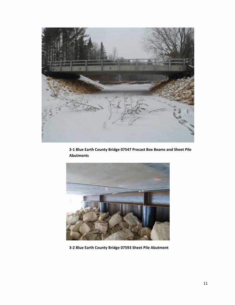
Innovation 3: Precast Box Beams and Sheet Pile Abutments – Blue Earth County (Bridges 07586,
07593 and 07547)
Description
Blue Earth County has constructed three bridges, 07586 over Little Cobb River and 07593 and 07547
over Big Cobb River, that consist of an adjacent precast box beam superstructure supported on sheet
pile abutments. Additionally, a two-line open metal railing was used for the bridge barriers. This design
is similar to bridges used in New York for low-volume roads, and was identified as having potential for
use in Minnesota during a scanning tour to New York that the Blue Earth County Engineer attended.
Bridges 07593 and 07547 were both constructed with bituminous overlays over waterproofing
membranes at the joints, while Bridge 07586 was built with a 5-inch composite CIP reinforced concrete
deck due to the higher ADT on CR 168. In 2012, the County is planning to construct two more bridges
with ADTs in the 3,000-4,000 range that will use precast adjacent box beams with a 6” reinforced
concrete composite/non-composite deck. See Appendix A3 for example details and additional photos of
this technique.
$147
$95
$91
$117
$106 $114
$104
$141
$-
$20
$40
$60
$80
$100
$120
$140
$160
2004 2005 2006 2007 2008 2009 2010 2011 2012
To
tal C
on
stru
ctio
n C
ost
($
/SF)
Year Built
Precast Inverted Tee Bridge Cost Data
Bridge No. 13004
Bridge No. 33005
Bridge No. 33008
Bridge No. 66004
Bridge No. 49007
Bridge No. 49036
Bridge No. 49003
Bridge No. 08006
11
3-1 Blue Earth County Bridge 07547 Precast Box Beams and Sheet Pile
Abutments
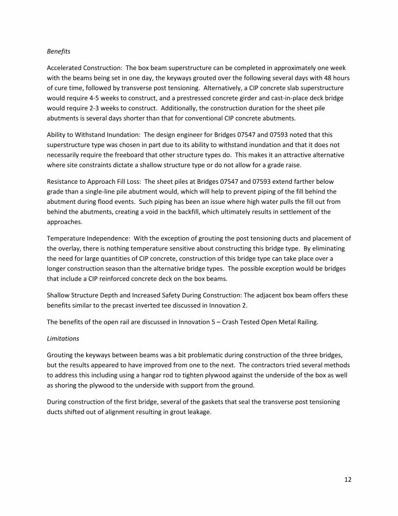
3-2 Blue Earth County Bridge 07593 Sheet Pile Abutment
12
Benefits
Accelerated Construction: The box beam superstructure can be completed in approximately one week
with the beams being set in one day, the keyways grouted over the following several days with 48 hours
of cure time, followed by transverse post tensioning. Alternatively, a CIP concrete slab superstructure
would require 4-5 weeks to construct, and a prestressed concrete girder and cast-in-place deck bridge
would require 2-3 weeks to construct. Additionally, the construction duration for the sheet pile
abutments is several days shorter than that for conventional CIP concrete abutments.
Ability to Withstand Inundation: The design engineer for Bridges 07547 and 07593 noted that this
superstructure type was chosen in part due to its ability to withstand inundation and that it does not
necessarily require the freeboard that other structure types do. This makes it an attractive alternative
where site constraints dictate a shallow structure type or do not allow for a grade raise.
Resistance to Approach Fill Loss: The sheet piles at Bridges 07547 and 07593 extend farther below
grade than a single-line pile abutment would, which will help to prevent piping of the fill behind the
abutment during flood events. Such piping has been an issue where high water pulls the fill out from
behind the abutments, creating a void in the backfill, which ultimately results in settlement of the
approaches.
Temperature Independence: With the exception of grouting the post tensioning ducts and placement of
the overlay, there is nothing temperature sensitive about constructing this bridge type. By eliminating
the need for large quantities of CIP concrete, construction of this bridge type can take place over a
longer construction season than the alternative bridge types. The possible exception would be bridges
that include a CIP reinforced concrete deck on the box beams.
Shallow Structure Depth and Increased Safety During Construction: The adjacent box beam offers these
benefits similar to the precast inverted tee discussed in Innovation 2.
The benefits of the open rail are discussed in Innovation 5 – Crash Tested Open Metal Railing.
Limitations
Grouting the keyways between beams was a bit problematic during construction of the three bridges,
but the results appeared to have improved from one to the next. The contractors tried several methods
to address this including using a hangar rod to tighten plywood against the underside of the box as well
as shoring the plywood to the underside with support from the ground.
During construction of the first bridge, several of the gaskets that seal the transverse post tensioning
ducts shifted out of alignment resulting in grout leakage.

13
Cost
Currently, the cost per square foot for the precast box beam bridges is higher than that for alternative
bridge types, but cost reductions can be expected with increased use. The following figures were
obtained from the MnDOT State Aid Bridge Office 2011 Calendar Year Report:
• Bridge 07547 $184.54/SF
• Bridge 07593 $178.93/SF
• Prestressed Girder Average (41 bridges) $118.83/SF
• Concrete Slab Average (13 bridges) $109.17/SF
Several factors contributed to the increased cost for this bridge type. While the beam shapes are based
on standard shapes used elsewhere, use of precast box beam sections is new to Minnesota bridge
construction, and the beams were cast at Wisconsin and Iowa plants where box beam forms are
available. Additionally, prior to these bridges, Minnesota contractors had not erected a structure using
precast box beams on sheet pile abutments, which also contributed to the increased cost. However, it is
promising to note that these projects had multiple bidders, which indicates interest from the contracting
community.
Based on the interview with the design engineer for Bridges 07547 and 07593, it is also important to
note that while the cost per square foot was higher for these bridges, the structure type was more
competitive on an overall project cost basis. All three bridges were simple spans with span lengths of
66-70 feet. A concrete slab structure would have required three spans to avoid a pier at mid stream,
and the bridge would likely have been lengthened to balance the spans. However, the design engineer
for Bridges 07547 and 07593 indicated that the County Engineer was not interested in having piers at
the edges of the stream due to issues with debris accumulation. The other alternative would have been
prestressed girders, which are more susceptible to complications caused by inundation and would have
required a grade raise to provide adequate freeboard. The grade raise would have increased the bridge
length, increased the earthwork and roadway costs, and potentially required additional right-of-way
acquisitions. For these reasons, the design engineer noted that the precast box beam bridge had a
comparable overall project cost at Bridge 07593 and a lower overall project cost at Bridge 07547.
Potential Actions to Promote further Implementation
Following construction of Bridge 07586, several modifications were made to the designs of Bridges
07593 and 07547 including the following:
Sheetpile Abutment Detail: The first bridge used the sheetpile abutments as the bearing support for the
superstructure, which resulted in excessive sheet pile lengths, difficulty establishing the bearing capacity
in the field, and extensive cutting and grinding the top of the sheeting to provide a level bearing surface.
At the subsequent locations, the superstructure was supported on a steel wide flange welded to the top
of a single row of steel pipe piles and the sheeting was installed behind the pipe piles to retain the
approach embankment. In addition to the reduced sheetpile quantity, this detailing was significantly
easier to construct.

14
Metal Railing Attachment: The metal railing at Bridge 07586 was extended off the bridge for the
transition to the guard rail. In future applications, the County Engineer believes that a conventional
plate beam guardrail transition connected to the metal railing would be less costly.
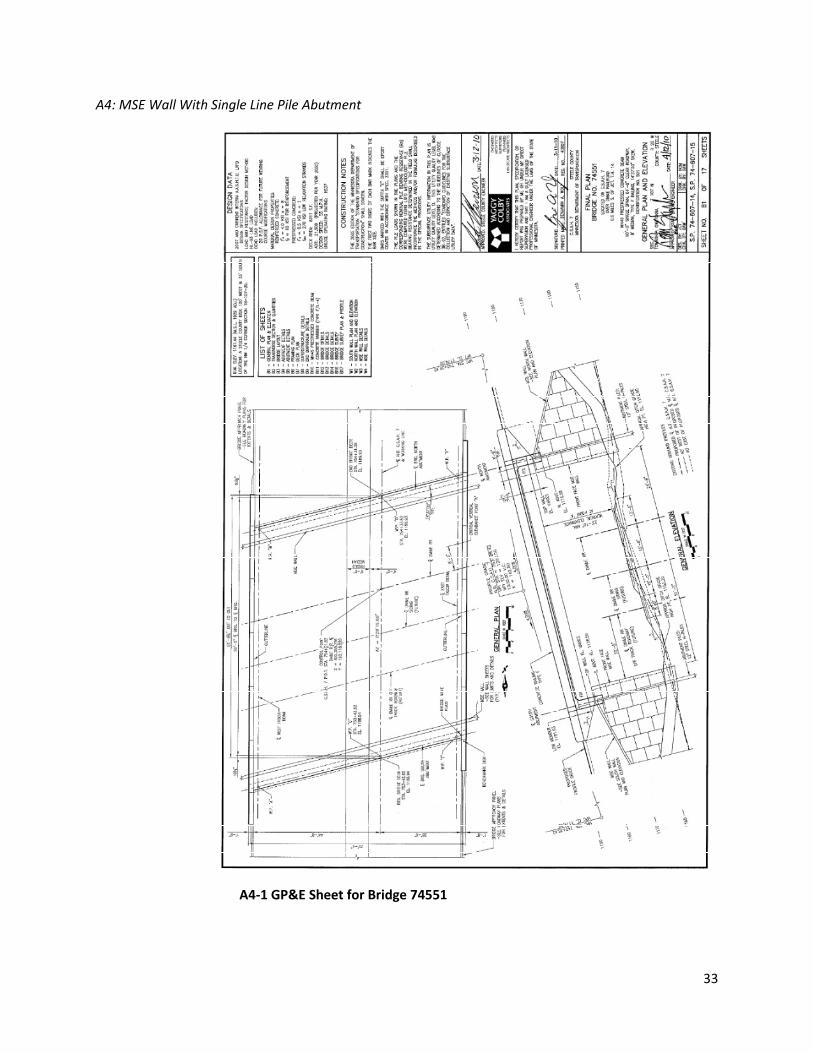
Innovation 4: MSE Wall With Single Line Pile Abutment – Steele County (Bridge 74551)
Description
In 2011, Steele County constructed a bridge that utilizes integral abutments on single rows of piles
behind MSE walls. While none of the individual components of this abutment type is unique, their use
in combination is innovative and unique on Minnesota’s local road system. Bridge 74551 is located on
CSAH 7 over the DM&E railroad in Owatonna. It is a single span prestressed girder structure with a span
length of 90’-0” from bearing to bearing and a vertical clearance of 23’-4” over the railroad. The
superstructure consists of a CIP deck on MN45 beams. Due to a highly compressible clay layer at the
project site, the embankments were surcharged for approximately four months prior to abutment
construction. In addition to surcharging the embankments, MnDOT installed instrumentation on the
piles to monitor settlement of the embankment and the corresponding down drag load on the piles.
The results of this monitoring will ultimately be combined with that done at other sites to develop
improved MnDOT procedures for drag load design. See Appendix A4 for an example GP&E sheet and
additional photos of this technique.
4-1 Steele County Bridge 74551
Benefits
This abutment type allowed for a bridge that was approximately 50% of the length of the 3-span
prestressed I-girder alternative that would have been required to meet all of the railroad clearance
requests within the federal participation guidelines. The 3-span structure would have had sideslopes in

15
the end spans with shorter abutments. Combined with the fact that the MSE abutment type uses less
concrete and less piling than a typical cast-in-place abutment, the overall cost of the bridge was
approximately 25% less than the alternative structure. Another alternative would have been a single
span bridge with tall CIP abutments, but that would also have been a more expensive structure.
A benefit of this structure type with regard to future maintenance is the absence of expansion joints on
the bridge.
In the case of compressible soils, this abutment type generally results in less settlement than a spread
footing would, and MSE walls are more tolerant of settlement than other wall types.
Limitations
Since this abutment type is not widely used on the local road system, the designer indicated that there
was additional time and effort involved in the structure type selection phase compared to a more
conventional structure configuration to establish the viability of this abutment type at this site.
Documenting successful use of this abutment type elsewhere was key to gaining approval.
Coordination between the MSE wall supplier and contractor is important to avoid construction delays,
and can be dependent on the experience and expertise of both parties. Ideally, the contractor would
have prior experience with MSE wall installation, and the MSE wall supplier would provide an
experienced project liaison.
This abutment type is sensitive to pile alignment, which was an issue on this project; so for future use,
the design engineer suggested paying particular attention to those details and including more stringent
plan notes to that effect. The designer also suggests, for future projects, allowing enough space
between the front face of the abutment and the MSE wall to allow for more construction tolerance.
Additionally, MSE systems generally should not be used where buried utilities may need to be installed
in the future. Disturbance of the reinforcing straps within the MSE backfill can threaten the structural
integrity of the wall system.
Cost
According to the designer, the cost of this bridge was approximately 25% lower than what the
alternative 3-span structure would have cost.
Potential Actions to Promote further Implementation
For future use of this abutment type, it is suggested to define standards and limitations with regard to
their use similar to when MnDOT began using integral abutments on the local road system. For
example, define the maximum allowable span length, skew angle, etc. for use without special review.

16
Innovation 5: Crash Tested Open Metal Railing – Polk County (Bridges 60588 and 60559)
Description
A crash tested open metal railing was utilized for several bridges in Polk County. In 2008, Bridges 60588
and 60559 over Sand Hill River were constructed using this railing based on a New York design identified
from a State Aid scanning tour. That railing is shown in the Photo 5-1 and has been crash tested to meet
Test Level 4 requirements for use in projects with design speeds over 40 mph. The bridges are
prestressed girder spans.
5-1 Polk County Bridge 60559 Metal Railing
Additionally, Blue Earth County has installed the metal railing on three projects with precast box beams
for the superstructure. The rail post to deck attachment was modified in the latter Blue Earth County
projects to connect the railpost to the side of the precast box girder superstructure. The Blue Earth
County projects used a two line metal railing, which meets the Test Level 2 standards for speeds of 40
mph or less.

17
5-2 Blue Earth County Bridge 07593
A modified version also meeting Test Level 4 for higher speed designs was later used in 2009-10 for
construction of Bridge 60561, CSAH 9 over the Red River in Polk County, east of Thompson, North
Dakota. See Appendix A5 for example details and additional photos of the metal railings.
Benefits
The Polk County Engineer noted the use of the metal railing design bolted directly to the deck allows the
elimination of deck drains. The open base allows an unobstructed flow of water off the bridge for low
volume roads. That avoids several issues such as the need to have sufficient grade to ensure the
drainage will carry off the ends of the bridge or to a deck drain without ponding, and debris blockage of
the deck drain. With the open railing design, light snow can be pushed through the railing depending on
the snow event. Blowing snow also does not accumulate against the open rail and at times allows the
deck to be blown clean.
Construction is more rapid than concrete rails since no forming, placing of reinforcement, or pouring
and curing is required. For projects where accelerated construction is desired the railing reduces
construction time.
The MnDOT State Aid Bridge Engineer further noted the open design increases visibility of traffic when
intersecting roadways are present at the end of a bridge.
For Bridge 60561 over the Red River, the open railing design allows motorists a view of the river and
valley, a more attractive design than a Type F solid concrete barrier. The metal rail can be painted if a
color is desired for aesthetics. Issues such as uneven concrete finishing are avoided.
Limitations
Overall maintenance cost could be higher if traffic hits are incurred compared to a concrete rail. The
bridges in Polk and Blue Earth County are on a tangent section of roadway, so the chance of vehicles

18
losing control and striking a rail are considerably less than a curved alignment. Severe traffic hits
however may require replacement of metal members. The bolted connections of railing to post and
post to deck allow for replacement of damaged pieces as long as the cast in place post anchorage
remains intact.
For higher traffic sites such as Bridge 60561, with 1,100 ADT, a more substantial 2-line rail with a
concrete curb was used. This allows motorists a more open view of the Red River Valley as they cross
the structure than a solid concrete rail. The design with the curb requires water be carried to either the
end of the bridge or deck drains, negating the drainage advantage.
Cost
Costs of the metal rails are currently higher than concrete railings. The MnDOT State Aid Bridge
Engineer provided cost information for the Polk County projects. The metal rails for Bridges 60588 and
60559 were bid at $220 per LF vs. $70 per LF typically bid for a concrete railing. With increased use the
metal design would become more competitive as fabricators and contractors are accustom to supplying
and installing the rail. In New York State, where the metal railing system use is common, costs are
actually less than concrete barriers.
Potential Actions to Promote further Implementation
The Polk County Engineer stated he would use the railing again for projects similar to the Sand Hill River
bridges or the Bridge 60561 replacement over the Red River. The rail was easily installed by the
contractor and went quickly, saving the time to form, pour and cure a concrete railing. Blue Earth
County also recognized the benefits of the railing for drainage and ease of installation and included
them for their precast box girder bridges. As more counties and designers become aware of the railing
use in Minnesota it has application on additional projects. While the cost is higher, the metal railing
only accounts for approximately 6% of total bridge cost.
Innovation 6: Large Precast Box Culverts – Aitkin County (Bridge 01J31) and Three-Sided Structures
(General)
Description
Aitkin County replaced an existing bridge with a large precast box culvert structure for Bridge No 01J31,
County Road 73 over the Sandy River (Co. Ditch #42) near McGregor, Minnesota. The structure is a 20
feet wide and 8 feet high (20’x8’) which exceeds the maximum span of 16 feet covered by the MnDOT
standard culvert designs tables. An engineer was retained to design the reinforcing and modify the
MnDOT standards, and the culvert was constructed in 2011.

19
6-1 Aitkin County Bridge 01J31
Benefits
A set of twin boxes was not desired at this location, so a large single box structure was chosen with the
intent of maintaining the full waterway opening across the entire width of the box.
From conducting bridge inspections for a number of years, the County Engineer noted that double and
triple box culvert installation often did not function hydraulically as envisioned. Quite frequently some
amount of channel change had been required during construction to align or modify the channel in an
attempt to direct the flow through the double/triple boxes. The stream however would soon migrate
back to its natural flow and primarily utilize only one of the culvert barrels. The second or third box
would silt in with sediment or debris, no longer providing the full hydraulic cross section.
After observing this tendency for a multiple barrel structure to partially silt in, the county developed a
preference for a single span structure where feasible.
During the design phase the size of the boxes was reviewed as noted above for constructability. The
county and designer believed local contractors would not have any issues building the culvert. This
assessment was confirmed by the fact eight bidders competed for the project, the typical small
contractors that bid on other projects in Aitkin County. No company expressed concerns to the County
regarding the box size or constructability.
Maintenance will be the same as for all precast box culvert structures, with the exception less debris and
sediment collection and corresponding cleanout should be needed in comparison to a multi-barrel box.
In general, the precast box culverts have required very little maintenance for structural items.

20
The County Engineer expects benefits over the life of the structure due to less maintenance required by
county forces to keep the culvert free of debris or sediment. For future projects he will consider use of
larger boxes and is using an 18-foot box for a project in 2012.
Limitations
For some sites, the access and placement of larger box sections may be an issue. Larger crane capacity
is required for placement of the sections. Additionally, shipping weight and size of boxes could be an
issue for trucking. The county explored those issues for this project and confirmed that the site allowed
adequate access for equipment and precasters could ship to the site.
Cost
The bid price for the 20’x8’ single box was $1,540 per LF, and end sections were bid at $16,000 each.
For comparison purposes, a recent Aitkin County bid for a 14’x6’ went for $850 per LF and $10,000 per
end section. Twin lines of 14’x6’ would approximate a single 20’x8’. Although that is just one
comparison, the County believes that the cost of the large single box is comparable to twin boxes of
equivalent area.
The project did come in close to the Engineer’s estimate. Estimated cost was $157,000 and actual low
bid was $166,000. In summary, the County did not see a premium paid for the innovation.
A significant cost for these structures is in the end sections. In lieu of the wide end sections for a 20-foot
box, the use of precast wingwalls should be considered. That decision will be site specific and the
roadway geometry must be considered.
Potential Actions to Promote further Implementation
At the County Engineers Bridge Subcommittee meeting in January 2012, it was requested that the use of
Large Culverts be added to the report so County Engineers are aware they can go beyond the limits of
the standard box culvert designs in the MnDOT tables. It does require retaining an engineer to do some
design, to extend the design for the longer width. Routine culvert spans within the limits of the
standard tables can be designed using MnDOT published standards.
The fact that these longer spans do require hiring an engineer could be a limitation to expanding usage
of longer spans. If other counties also choose to use longer spans and the demand develops, then the
standard MnDOT culvert tables should be expanded once again, beyond the current 16-foot span. The
tables have been expanded in the past for these reasons.
Three-Sided Structures
In addition to large precast box structures, there has been an increased use of three-sided structures for
local roads and the MnDOT Trunk Highway system. Three-sided structures are precast but do not have
a bottom slab. The legs bear on a footing that is cast in place on the site.

21
Spans for the three-sided structures can go up to 60 feet, however the common spans are typically 28 to
42 feet. Similar to box culverts, the structure is built from a series of precast sections that are sized for
shipping and lifting.
Benefits of three-sided structures include the fact it is a low maintenance structure being a culvert, and
the stream bottom is undisturbed and maintains a natural bottom. The natural bottom is preferred in
streams where there is concern for fish migration or habitat.
Limitations include the fact that scour susceptible sites can require a pile foundation, which increases
the cost of the structure significantly. The roadway barrier on top of the structure is typically a moment
slab, where the railing is anchored into the pavement to prevent the railing from overturning from
traffic hits. The three-sided structure is not designed to anchor the barrier railing directly.
Cost are usually higher than precast box culverts, so use of a three-sided structure is typically at sites
where the open bottom is needed or the arch-like appearance is desired for aesthetics .
Photo 6-2 shows a three-sided structure under construction in Morrison County; see Appendix A6 for an
example GP&E sheet for this technology as well as photos of MnDOT Bridge 16X03.
6-2 Morrison County Bridge 49J44
Recommendations for Research or Implementation
During the interviews with County Engineers, the MnDOT State Aid Bridge Engineer, and FHWA, it was
asked if they had any recommendations for research regarding innovative construction or technologies
that should be considered for implementation. It was noted by a county engineer that Minnesota
counties, MnDOT and industry have made good progress in the last 20 years and innovations have been
made available. The counties have done a good job expanding usage and implementing new designs,
and it is believed that trend will continue in the future.

22
The following is a listing of the ideas suggested or comments offered in response to the question:
• For the local road system, cost is probably a more significant driver than Accelerated Bridge
Construction (ABC). Costs for any system need to be driven down to gain increased use.
That can occur as fabricators become accustom to casting new sections and contractors
become familiar with the new method of construction.
• Construction costs may also be reduced by having competing structure types, however the
design costs of developing alternative systems is a barrier unless standard plans are
available similar to the box culvert standards.
• When successful projects are completed, those need to be marketed to county engineers
and bridge owners so they are aware of the benefits and the limitations. Success in one
county increases the likelihood another will try the innovation.
• The scanning tours have helped to make county engineers, State Aid, and designers aware
of the methods used in other states. The upcoming scan to Iowa in 2012 includes ultra high
performance concrete, GRS abutments, and precast slab span panels. That information will
be shared with Minnesota county engineers and provides an opportunity to try additional
technologies.
• Some innovations, such as precast box culverts or precast inverted tees, will benefit from
development of standard designs. This can aid designers and owners in specifying the
bridge type, reducing the design effort. Extension of the precast box culvert standards from
the current 16 foot to 18 or 20 foot was mentioned.
• Similar to the previous comment, as an aid to designers of county bridges, a design example
of a multiple span inverted tee could be developed. This would provide them the method
MnDOT has used to consider the continuity and time dependent behavior of the sections.
This would lessen the learning curve in implementing inverted tee designs and assist
designers for local roads since the design budgets for these projects are limited.
• Consider investigating if the span of the MnDOT inverted tee could be extended further
than the 55-60-foot limit by section modifications such as; 1) increasing the web depth and
introducing a void similar to a box beam to reduce the weight, and 2) adding additional post
tensioning with the added depth.
Opportunities for Federal Funding of Innovative Designs
The typical federal funding sources available for any local road bridge project are of course available for
projects involving innovations. The following federal funding programs are additional programs
specifically developed to encourage innovations and were discussed in an interview with the FHWA
Minnesota Division Bridge Engineer:
Innovative Bridge Research and Deployment (IBRD)
The IBRD program provides federal funds for projects that demonstrate innovative accelerated bridge
design and construction technology, and the application of innovative material technology for bridges.
The program was funded within the SAFETEA-LU federal transportation act and has been extended via

23
the Surface Transportation Extension Act for Fiscal Year 2012. Solicitations for IBRD and the Highways
for Life Program most recently occurred in January of 2012. The FHWA solicits projects from the states,
reviews applications based on conformance with the program goals, and selects projects according to
available funding. The IBRD program funding amounts vary yearly with congressional appropriations
and have ranged from $4 to $13 million. Individual projects selected vary in funding amounts from as
low as $30,000 to $400,000 or greater.
The goals of the program include development of cost-effective highway bridge applications and
construction techniques, development of engineering design criteria for innovative products, materials
and structural systems, and effective transfer of resulting information and technology. The FHWA
website contains more detailed information.
Several Minnesota projects have received IBRD funding in past years. For the local road system, the
Rock County Bridge 67564 received $350,000 for the use of Geosynthetic reinforced soil (GRS)
abutments. That project is described within the synthesis report and will be constructed in 2012.
It is unknown if the next federal transportation funding act will continue the IBRD program. The
programs within each act will be determined by Congress.
Highways for Life
The Highways for Life program has also been a source of funds for innovative construction. MnDOT’s
replacement of the Maryland Avenue Bridge over I-35E in St. Paul was partially funded by this program.
Construction of that project will begin in May of 2012 and includes the first use of self propelled
modular transporters (SPMT). The bridge superstructure (beams and deck) will be built off the I-35E
alignment on falsework and moved over a weekend inplace on the new piers by the SPMTs. This
eliminates beam erection and deck construction over the active interstate.
MnDOT has also applied for Highways for Life funding for a TH 61 project to build a bridge and slide it
into position in the Rochester District and for construction using full depth precast concrete deck panels
in the Duluth District.
The Highways for Life program projects are typically larger projects than IBRD in terms of funding, often
several million in cost. For local road use, the IBRD program is a more likely source of funding.
Similar to IBRD, it is unknown if the next transportation act will continue the Highways for Life program.

24
Innovative Bridge Techniques Summary
See the individual technology sections for more detailed discussion.
Technique Description Considerations for Use Cost Information
Geosynthetic-
Reinforced Soil (GRS)
Abutments
• Bridge length ≤ 140 ft
• Abutment height ≤ 24 ft
• Soil bearing pressure capacity ≥ 4,000 psf
• Good for overpasses of roadway or RR
• Not recommended at waterway crossings with potential
for scour
• Allows more rapid construction than CIP
Cost savings of 25-60%
per FHWA est.
Precast Inverted Tee
Slab Span Bridges
• Span length ≤ 60 ft
• Shallow superstructure locations – good replacement for
timber or CIP slabs
• Rapid construction, est. construction time savings of 20-
40%
• More complex design than CIP slab, learning curve for
new designers
Cost approx.10-15%
higher than CIP slab per
MnDOT est. Cost has
declined as more
structures have been
built.
Precast Box Beams
and Sheet Pile
Abutments
• Rapid construction with limited temperature dependence
• Shallow superstructure, good for locations subject to
inundation
• Learning curve with first-time contractors
• Precast box beams and sheet pile abutments are
separate innovations that can be used in combination or
with other types of abutments and superstructures.
• Max. span length for 27” box beam is approx. 90 ft.
Cost/SF approx. 50%
higher than prestressed
beam or CIP slab per
MnDOT State Aid Bridge
Office data, but can be
offset by shorter bridge
and less grading (see
p.12).
MSE Wall with Single
Line Pile Abutment
• Good for overpasses of roadway or RR
• Can provide shorter bridge than with sideslopes
underneath
• Can provide lower cost bridge than with tall CIP
abutments
• No expansion joints on bridge
Cost approx. 25% lower
than alternative
structure type per design
engineer
Crash Tested Open
Metal Railing
• Three-line rail crash tested to meet TL-4 (design speed >
40 mph)
• Two-line rail crash tested to meet TL-2 (design speed ≤
40 mph)
• Open base allows unobstructed water flow off bridge
deck
• Increased visibility for traffic
• Alt. installation with concrete curb
Currently higher cost
than concrete railing
Large Precast Box
Culverts
• Aitkin Co. used 20’x8’
• Minimizes silting and debris collection versus twin boxes
• Box size did not present additional constructability
issues, but may not be feasible for sites with access or
trucking limitations
Aitkin Co. project cost of
large single box was
comparable to cost of
twin boxes with
equivalent area
Three-Sided Structures • Common spans of 28-42 ft
• Natural stream bottom retained
• Requires CIP footings
• Scour susceptible sites can require piles
Typ. higher cost than
precast box culverts, so
best for sites that
require aesthetics or
natural bottom

25
Appendix
A1: Geosynthetic-Reinforced Soil (GRS) Abutments
A1-1 GP&E Sheet for Bridge 67564

26
A1-2 GRS Abutment Plan Sheet for Bridge 67564

27
A1-3 GRS Abutment Detail Sheet for Bridge 67564

28
A2: Precast Inverted Tee Slab Span Bridges
A2-1 GP&E Sheet for Bridge 70548

29
A2-2 Drop-in reinforcing cage between inverted tee sections
A2-3 MnDOT precast inverted tee Bridge 13004

30
A3: Precast Box Beams and Sheet Pile Abutments
A3-1 GP&E Sheet for Bridge 07547

31
A3-2 Sheetpile Abutment Detail for Bridge 07547
A3-3 Bridge 07547 construction

32
A3-4 Sheetpile abutment at Bridge 07593
A3-5 Sheetpile abutment wing at Bridge 07593
33
A4: MSE Wall With Single Line Pile Abutment
A4-1 GP&E Sheet for Bridge 74551

34
A4-2 MSE Wall Detail for Bridge 74551
A4-3 MSE Wall Construction for Bridge 74551

35
A4-4 MSE Wall and Abutment Piles for Bridge 74551
A4-5 MSE Wall and Abutment Piles for Bridge 74551

36
A5: Crash Tested Open Metal Railing
A5-1 GP&E Sheet for Bridge 60559

37
A5-2 Railing Elevation Detail for Bridge 60559
A5-3 Section Thru Railing Detail for Bridge 60559

38
A5-4 Section Thru Two-Line Railing on Blue Earth Co. Bridge 07547
A5-5 Two-Line Railing Attachment on Blue Earth Co. Bridge 07593

39
A6: Large Precast Box Culverts and Three-Sided Structures
A6-1 GP&E Sheet for Morrison Co. Bridge 49J44

40
A6-2 MnDOT Bridge 16X03 over Kimball Creek; 32-foot span (courtesy of
Cretex Concrete Products)
A6-3 MnDOT Bridge 16X03 over Kimball Creek; 32-foot span (courtesy of
Cretex Concrete Products)