innovations technology to take you forward. - saro...
TRANSCRIPT

_INNOVATIONS
Technology to take you forward.
Product innovations Edition 2010-1
Turning, drilling, threading and milling
In these catalogues, catalogue supplements and this first edition of the new products brochure 2010, “Technology to take you forward”, you will find the full range of tools of our three excellent brands – Walter, Walter Titex and Walter Prototyp.
They contain all the precision tools you need in your production facilities for turning, boring, milling and threading.
We will be pleased to send you any of our catalogues, catalogue supplements and brochures on request.
= the full range of tools
+
+
+
Tool innovations
Tool innovations
Tool innovations
Technology to take you forward.

Engineering what you envision takes tools. Tools for turning, milling, drilling and threading. But it also takes heart and soul. From the initial inspiration to the final application. We’re driven to find out what our customers want and committed to make it happen. We concentrate on the applications and what you need them to do. We help you engineer the engineering. To us, perfection is practical. It’s the most productive and efficient way to achieve results, and the only way to turn vision into reality.
Expect more. Engineer what you envision.
Turning visions inTo rEaliTy.
Turning
Drilling & ThrEaDing
Milling
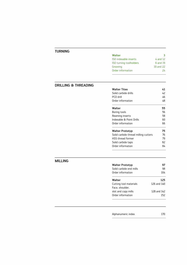
Walter 3ISO indexable inserts 4 and 12ISO turning toolholders 6 and 19Grooving 10 and 22Order information 24
Walter Titex 41Solid carbide drills 42PCD drill 46Order information 48
Walter 55Boring tools 56Reaming inserts 58Indexable & Point Drills 60Order information 66
Walter Prototyp 75Solid carbide thread milling cutters 76HSS thread former 79Solid carbide taps 82Order information 84
Walter Prototyp 97Solid carbide end mills 98Order information 104
Walter 125Cutting tool materials 126 and 140Face, shoulder, slot and copy mills 128 and 142Order information 152
Alphanumeric index 170
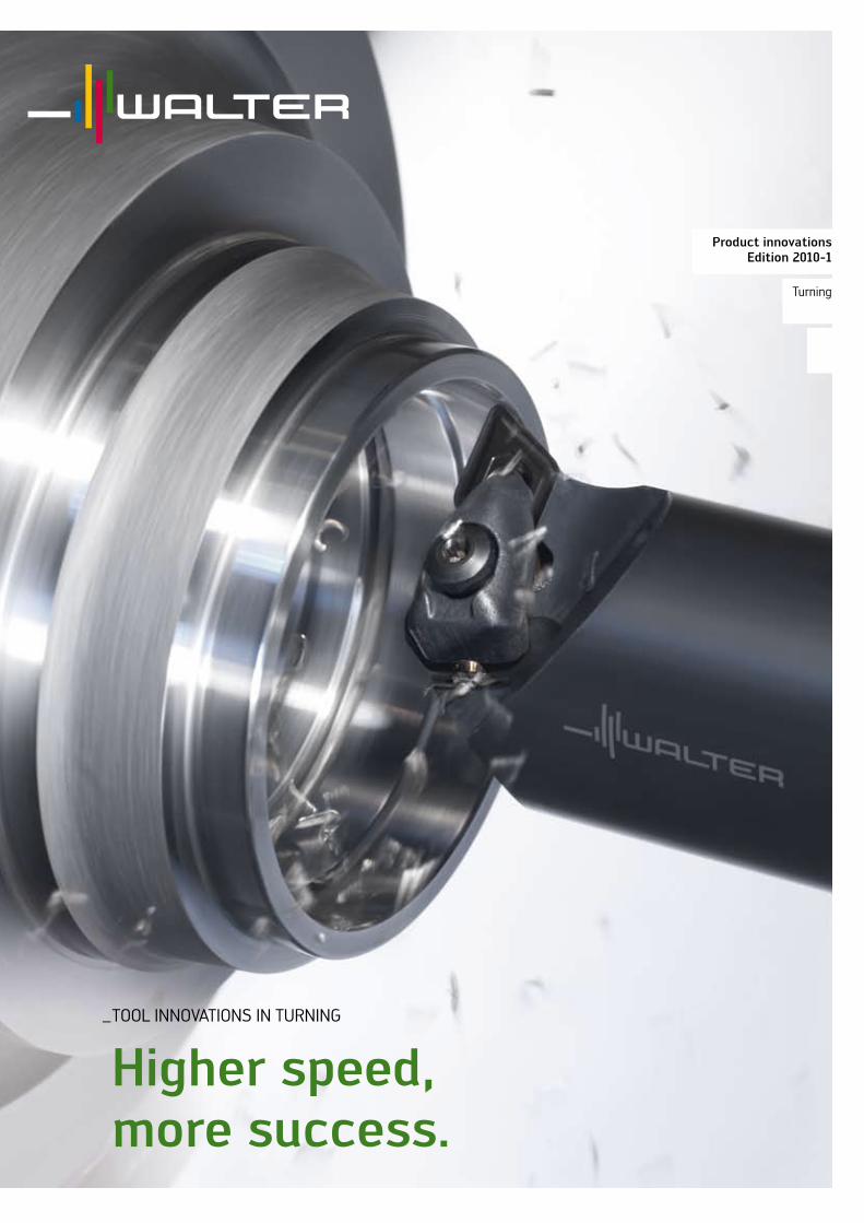
_TOOl InnOvATIOnS In TuRnInG
higher speed, more success.
Product innovations Edition 2010-1
Turning

ISO TuRnInG
nrr geometry – a winner for heavy-duty roughing.
4
Chip guide – reduces friction
Straight cutting edge design – maximum insert thickness
Shouldered negative protective chamfer – for stability
nRR indexable insert geometry
aPPlicaTions
Forged parts with variable material removal –and ‘first pass’ machining. Casting skins as often encountered in the power –generation industryHeaviest roughing with high feed rates –High powered lathes to give maximum cutting rates –Typical components: marine engine crankshafts, generator –shafts, railway wheels, etc.
ThE inDExablE insErTs
Single-sided indexable insert for heavy-duty roughing –Tough cutting edge design with protective chamfer –Chip guide to reduce friction –Straight cutting edge for maximum stability –Basic shapes: C, S and T –Tiger·tec – ® cutting materials: WPP10, WPP20, WPP30 and WAK30 for steel and cast iron machining
NEW2010
your aDvanTagEs
Shouldered negative protective chamfer to reduce cutting –pressure thereby lengthening tool life Extremely heavy-duty – Tiger·tec® WAK30 cutting materi-als, preventing indexable insert breakages and thereby saving tool costs, even under extreme conditionsChip guides, which reduce the friction surfaces and –thus reduce the machining temperature – which in turn increases tool life

5Walter – Turning
rotor shaft 6 m in length – roughing through cast skin
cutting data
competitor Walter NRRvc 60 m/min 60 m/minf 1.2 mm 1.2 mmap 8 - 20 mm 8 - 20 mm
comparison of tool life per cutting edge [min]
Workpiece material: 42CrMo4 / 800 n/mm2
(1.7225)indexable insert: SnMM250924-nRRcutting tool material: WAK30Tool: PSBnl4040S25lead angle: 75°
0 6030 90 120 150 [min]
Competitors 85
Tiger·tec® Steel 125
+55 %
Notes:no insert breakage – to end of tool life of 2 h and 5 min, reliability and long life with Walter WAK30 Tiger·tec® cutting tool material.
nrr chiP brEaking rangE
The nRR geometry is used for the heaviest roughing applications on forged skins. It covers the range of applications above the nRF geometry, which was designed for universal roughing. Between them, these two geometries cover the full sphere of roughing applications.
T – basic shape nRR
S – basic shape nRR
C – basic shape nRR
Machining conditions
16
20
10
6.3
4.0
2.5
1.6
1.0
0.63
0.4
0.25
0.16
0.10.025
0.040.063
0.10.16
0.250.4
0.631.0
1.6
ap [mm] Depth of cut
f [mm]Feed
2.5
NRF
NRR

WalterCaptoTM
Walter Capto™ C8: 80 mm
ISO TuRnInG
Walter capto™: the new c8 size – capable of withstanding huge forces.
6
Walter Capto™ C8
80 mm
The Walter Capto™ range has been expanded to include the C8 size. This means the high-precision tool-change system is now available in sizes C3, C4, C5, C6 and C8, finished in accordance with ISO 26623.
ThE inTErfacE
Walter Capto™ C8 – manufactured for difficult –machining applicationsOvercome highest cutting forces with Walter Capto™, –which has an 80 mm collar diameter on C8 toolsRepeat tool change accuracy of +/- 0.002 mm –
aPPlicaTions
large vertical lathes –For wheel machining in the railway industry –In the power generation and wind energy industries for the –machining of rotor hubs, tower bearings, turbine shaftsIn the aerospace industry on turning and milling centres –
NEW2010
your aDvanTagEs
Time savings on tool change in comparison with –conventional square shanksTools can be preset – particularly important for –large and expensive componentsHigher forces can be transferred via the poly- –gonal form of the Walter Capto™ interface, both in turning and milling machining
Walter Capto™ C6: 63 mm
Walter Capto™ C5: 50 mm
Walter Capto™ C4: 40 mm
Walter Capto™ C3: 32 mm
7Walter – Turning
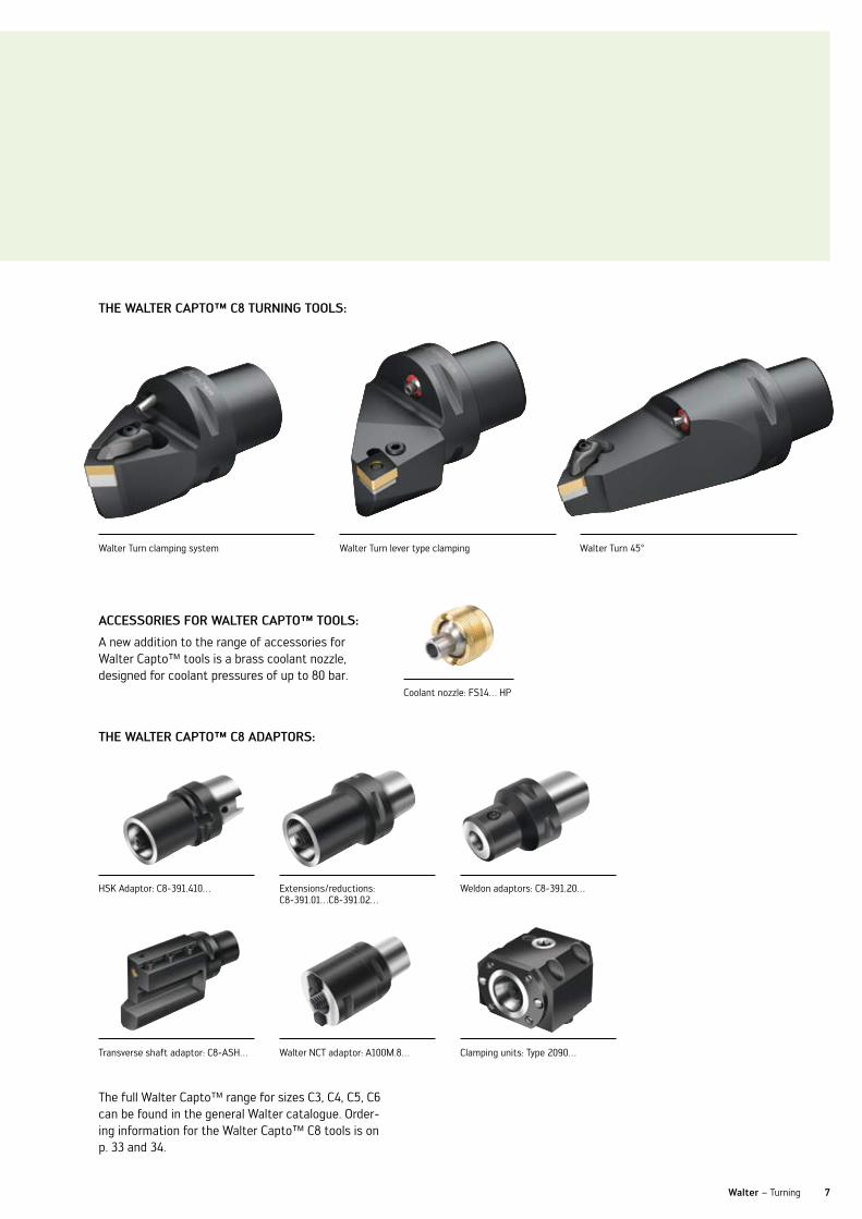
accEssoriEs for WalTEr caPTo™ Tools:
A new addition to the range of accessories for Walter Capto™ tools is a brass coolant nozzle, designed for coolant pressures of up to 80 bar.
ThE WalTEr caPTo™ c8 aDaPTors:
HSK Adaptor: C8-391.410… Extensions/reductions: C8-391.01…C8-391.02…
Weldon adaptors: C8-391.20…
Transverse shaft adaptor: C8-ASH… Walter nCT adaptor: A100M.8… Clamping units: Type 2090…
ThE WalTEr caPTo™ c8 Turning Tools:
Walter Turn clamping system Walter Turn lever type clamping Walter Turn 45°
Coolant nozzle: FS14… HP
The full Walter Capto™ range for sizes C3, C4, C5, C6 can be found in the general Walter catalogue. Order-ing information for the Walter Capto™ C8 tools is on p. 33 and 34.

ISO TuRnInG
Walter Turn boring bars – a major development for small diameters.
8
The Walter Turn boring bar range has been expanded to include the machining of small diameters in the range of 6 - 16 mm.
ThE Tool
Design of the boring bar –Steel shank•Solid carbide shank•
Shank design –Round shank•Round shank with clamping flats•
Internal coolant supply on all tools –Reliable TORX PluS – ® screw clampingPositive ISO insert types C, D, T and W –
ThE aDaPTor slEEvE – ak600
Easy handling thanks to automatic location of the –centre height by the AK600… adaptor sleeves for boring bars with a spring-loaded ballRound shank boring bars are completely enclosed –offering higher stabilityExternal diameters: 25, 32, 40 mm –Internal diameters for boring bars: –6, 8, 10, 12, 16, 20 mm
your aDvanTagEs
The AK600 adaptor sleeve ensures precise –adjustment to centre height for vibration-free machiningAutomatic alignment of the centre height also –saves time during tool changelow risk of vibration occurring due to optimum –angle of inclination and sharper microgeometry of the indexable insertsSolid carbide and steel boring bars can be –clamped in the same adaptor sleeve
Internal coolant supply
Available with solid carbide or steel shank
Optimised angle of inclination
NEW2010
AK600 adaptor sleeve with location of centre height
location groove for alignment to centre height

9Walter – Turning
TCGT06T1…-PF2 WXn10
ThE coolanT aDaPTor – k600
For sealing boring bars with clamping flats –Easy connection to the machine –no screw thread is needed –Easy to shorten the boring bar –Can be used as standard up to 80 bar coolant pressure –
ThE inDExablE insErT
new to the range for the machining of small diameters below –8.5 mm – the TCGT06T1… and the TCMT06T1… indexable insertsSpecially-developed cutting tool material WSM21 for the –machining of smaller diameters, which protects against microscopic chippingGeometry variants: –
PF2 “The sharp one”• PF4 “The fine one”•TCMT06T1…-PF4 WSM21

GROOvInG
g1042 deep parting blades with self-clamping.
10
ThE Tool
Deep parting blades for double-edged GX grooving system –Optimised insert seat design –4-point clamping –new clamping system for holding the insert –neutral tool design –Blade height 32 mm –
aPPlicaTions
For grooving and parting off on all types of lathes –For parting off with blade overhang of up to 60 mm –For parting off operations up to diameter 46 mm –(cutting depth 23 mm) with double-ended inserts
your aDvanTagEs
Deep parting blade for double-ended insert –Maximum stability between insert and tool –by means of 4-point clampingTwo insert seats in the tool body –Tool projection adjustable (maximum stability) –
NEW2010
new insert seat design with 4-point clamping
Self-clamping for GX range insert
Deep parting blades Type: G1042
neutral tool design
Double-ended GX insert
11Walter – Turning
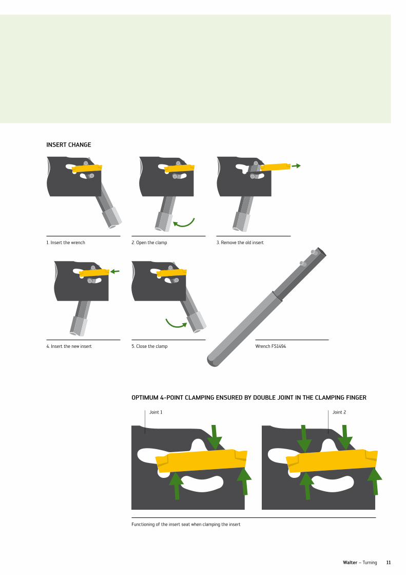
insErT changE
1. Insert the wrench 2. Open the clamp 3. Remove the old insert
4. Insert the new insert 5. Close the clamp
Functioning of the insert seat when clamping the insert
oPTiMuM 4-PoinT claMPing EnsurED by DoublE joinT in ThE claMPing fingEr
Joint 1 Joint 2
Wrench FS1494
12
ISO TuRnInG
Walter sky·tec™ – new nfT, nMT, nrT geometries: unique for titanium machining.
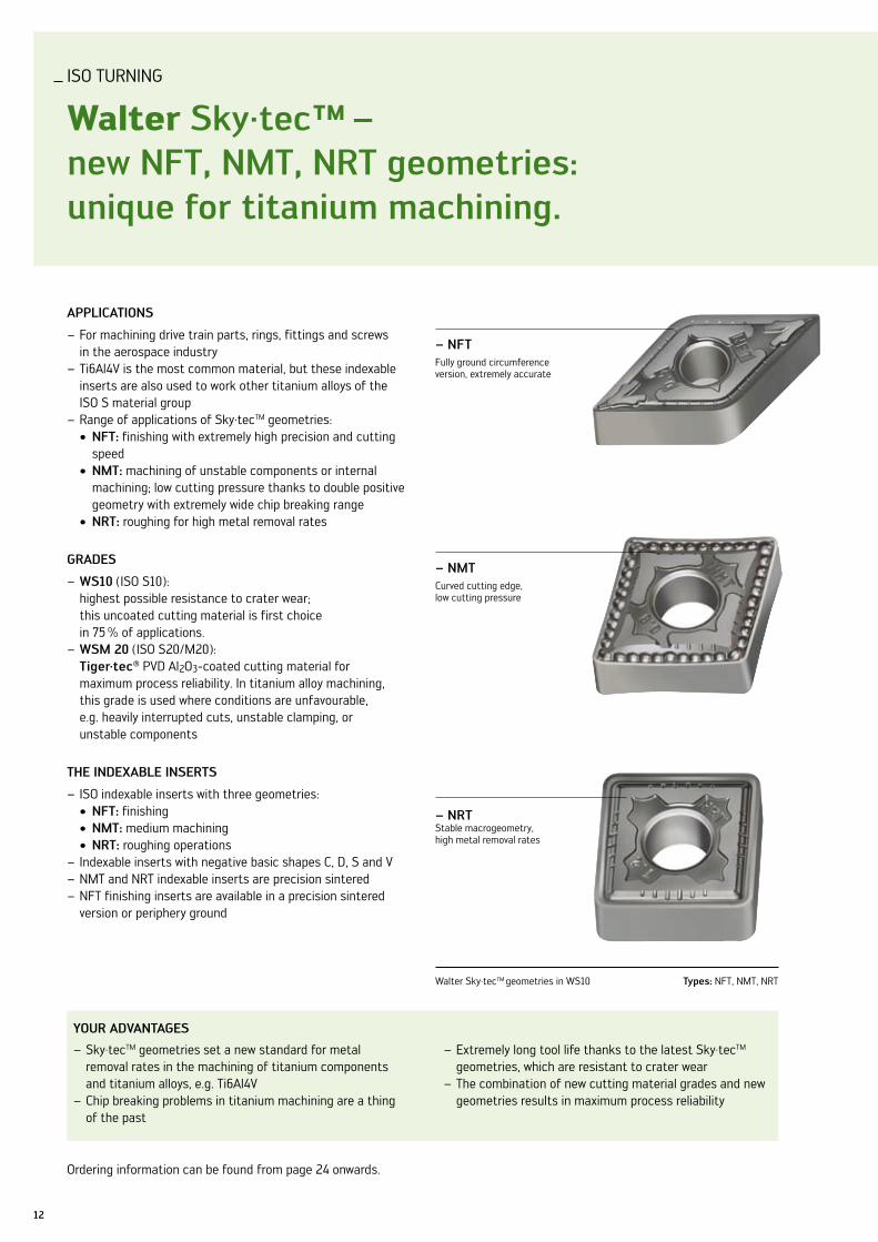
Walter Sky·tecTM geometries in WS10 Types: nFT, nMT, nRT
aPPlicaTions
For machining drive train parts, rings, fittings and screws –in the aerospace industry Ti6Al4v is the most common material, but these indexable –inserts are also used to work other titanium alloys of the ISO S material groupRange of applications of Sky·tec – TM geometries:
nfT:• finishing with extremely high precision and cutting speednMT:• machining of unstable components or internal machining; low cutting pressure thanks to double positive geometry with extremely wide chip breaking rangenrT:• roughing for high metal removal rates
graDEs
Ws10 – (ISO S10): highest possible resistance to crater wear; this uncoated cutting material is first choice in 75 % of applications.WsM 20 – (ISO S20/M20): Tiger·tec® PvD Al2O3-coated cutting material for maximum process reliability. In titanium alloy machining, this grade is used where conditions are unfavourable, e.g. heavily interrupted cuts, unstable clamping, or unstable components
ThE inDExablE insErTs
ISO indexable inserts with three geometries: –nfT:• finishingnMT:• medium machiningnrT:• roughing operations
Indexable inserts with negative basic shapes C, D, S and v –nMT and nRT indexable inserts are precision sintered –nFT finishing inserts are available in a precision sintered – version or periphery ground
your aDvanTagEs
Sky·tec – TM geometries set a new standard for metal removal rates in the machining of titanium components and titanium alloys, e.g. Ti6Al4vChip breaking problems in titanium machining are a thing –of the past
Extremely long tool life thanks to the latest Sky·tec – TM geometries, which are resistant to crater wearThe combination of new cutting material grades and new –geometries results in maximum process reliability
– nfTFully ground circumference version, extremely accurate
– nMTCurved cutting edge, low cutting pressure
– nrTStable macrogeometry, high metal removal rates
Ordering information can be found from page 24 onwards.

75°
95°
13Walter – Turning
ThE nfT gEoMETry
Thanks to this newly developed design, the nFT geometry with basic shape C automatically reduces cutting material costs by 50 %. The 80° corner of a CnMG indexable insert has been assigned the nFT finishing geometry and the 100° corner the nRT roughing geometry. As a result, a CnMG . . . –nFT indexable insert offers 8 fully effective edges in the respective, optimum geometry.
basic shape c, nfT geometry: roughing geometry –nrT on 100° corner
Walter – Turning
Turbine housing Ø 1,800 mm – Ti6al4v cutting data
competitor WS10vc 55 m/min 55 m/minf 0.4 mm 0.5 mmap 2.3 mm 2.3 mm
Tool lifeapprox. 3 cutting edges per component required
1 cutting edge per component required
Tool life [min] comparison
0 2010 4030 6050
Competitor 19
WS10 52
+180 %
Workpiece material: Ti6Al4v (3.7165)indexable insert: SnMG120412-nRTcutting tool material: WS10Tool: C6-PSKnl27140-12
basic shape c, nfT geometry: finishing geometry –nfT on 80° corner
note: nRT geometry has very good chip breaking properties throughout the entire life of the tool, i.e. no cratering of the indexable insert
[min]

14
ISO TuRnInG
Walter WsM10, WsM20 and WsM30 – stable, reliable, unique.
Sharp cutting edges
PvD Al2O3 coating
High cutting edge stability
Indicator coating
Machining conditions
Wear resistance
Toughness
good medium unfavourable
The ordering information for WSM10 can be found from page 24 onwards.
Walter WSM10 / WSM20 / WSM30 Geometry: nM4
With this world first development, it is now possible, for the first time ever, to deposit aluminium oxide (Al2O3) in a PvD process to carbide indexable inserts.
ThE cuTTing Tool MaTErial
Increased resistance to wear and temperature compared –to all previous PvD coatings, thanks to PvD aluminium oxideMaximum process reliability thanks to the low coating – temperature of the PvD coating very smooth cutting surfaces and sharp cutting edges –thanks to the Tiger·tec® coating processExcellent toughness, as with current PvD coatings –
your aDvanTagEs
A process reliability that has never before been achieved. –This is due to a micrograin substrate, combined with the Tiger·tec® coatingMaximum hot hardness thanks to the temperature- – resistant Al2O3 coating, resulting in maximum wear resistanceSharp cutting edges – thanks to the PvD coating – – ensure burr-free components and a reduction to the formation of built-up edgeOutstanding wear detection thanks to the – Tiger·tec® indicator coating
WSM30
WSM20
WSM10
Wear resistance
Toughness
Previous PvD grades
WSM PVD Al203
15Walter – Turning
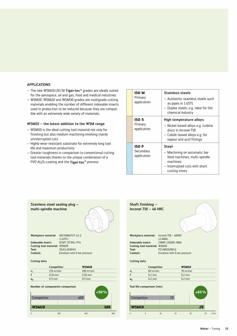
stainless steel sealing plug – multi-spindle machine
shaft finishing – inconel 718 – 46 hrc
cutting data
competitor WSM20vc 170 m/min 190 m/minf 0.18 mm 0.18 mmap 0.5 mm 0.5 mm
cutting data
competitor WSM10vc 60 m/min 70 m/minf 0.2 mm 0.2 mmap 0.2 mm 0.2 mm
Tool life comparison [min]
0 105 15 20 25
Competitor 15
WSM10 25
+65 %
Workpiece material: X6CrniMoTi17-12-2(1.4571)
indexable insert: DCMT 11T304–PF4cutting tool material: WSM20Tool: SDJCl1616H11coolant: Emulsion with 6 bar pressure
Workpiece material: Inconel 718 – 46HRC (2.4668)
indexable insert: CnMG 120408–nM4cutting tool material: WSM10Tool: PClnR2020K12coolant: Emulsion with 6 bar pressure
aPPlicaTions
The new WSM10/20/30 – Tiger·tec® grades are ideally suited for the aerospace, oil and gas, food and medical industriesWSM10, WSM20 and WSM30 grades are multigrade cutting –materials enabling the number of different indexable inserts used in production to be reduced because they are compat-ible with an extremely wide variety of materials.
WsM10 – the latest addition to the WsM range
WSM10 is the ideal cutting tool material not only for – finishing but also medium machining involving mainly uninterrupted cutsHighly wear-resistant substrate for extremely long tool –life and maximum productivityGreater toughness in comparison to conventional cutting –tool materials thanks to the unique combination of a PvD Al2O3 coating and the Tiger·tec® process
ISO MPrimary application
stainless steels
Austenitic stainless steels such –as pipes in 1.4571Duplex steels, e.g. valve for the –chemical industry
ISO SPrimary application
high temperature alloys
nickel-based alloys e.g. turbine –discs in Inconel 718 Cobalt-based alloys e.g. for –vapour and acid fittings
ISO PSecondary application
steel
Machining on automatic bar –feed machines, multi-spindle machines Interrupted cuts with short – cutting times
[min]
number of components comparison
0 200 400 600
Competitor 400
WSM20 600
+50 %
16
ISO TuRnInG
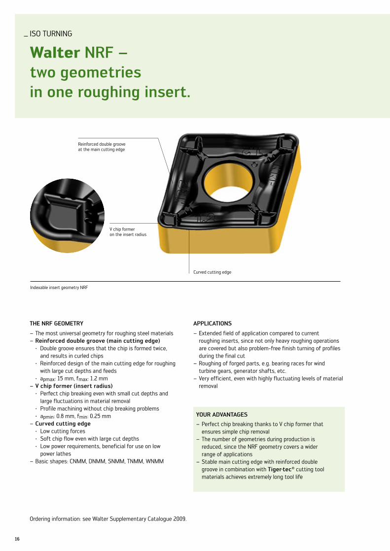
Walter nrf – two geometries in one roughing insert.
v chip former on the insert radius
Reinforced double groove at the main cutting edge
Indexable insert geometry nRF
Ordering information: see Walter Supplementary Catalogue 2009.
ThE nrf gEoMETry
The most universal geometry for roughing steel materials –reinforced double groove (main cutting edge) –
· Double groove ensures that the chip is formed twice, and results in curled chips
· Reinforced design of the main cutting edge for roughing with large cut depths and feeds
· apmax: 15 mm, fmax: 1.2 mmv chip former (insert radius) –
· Perfect chip breaking even with small cut depths and large fluctuations in material removal
· Profile machining without chip breaking problems · apmin: 0.8 mm, fmin: 0.25 mm
curved cutting edge – · low cutting forces · Soft chip flow even with large cut depths · low power requirements, beneficial for use on low
power lathesBasic shapes: CnMM, DnMM, SnMM, TnMM, WnMM –
aPPlicaTions
Extended field of application compared to current –roughing inserts, since not only heavy roughing operations are covered but also problem-free finish turning of profiles during the final cutRoughing of forged parts, e.g. bearing races for wind –turbine gears, generator shafts, etc.very efficient, even with highly fluctuating levels of material –removal
your aDvanTagEs
Perfect chip breaking thanks to v chip former that – ensures simple chip removalThe number of geometries during production is –reduced, since the nRF geometry covers a wider range of applicationsStable main cutting edge with reinforced double –groove in combination with Tiger·tec® cutting tool materials achieves extremely long tool life
Curved cutting edge

17Walter – Turning
Walter Tiger·tec® steel – increases productivity when turning steel.
Wear resistance
Toughness
good medium unfavourable
WPP30WPP20
WPP10
WPP05
WPP01
ap: 2.5 mm, f: 0.7 mm
ap: 10 mm, f: 1.0 mm
roughing ball bearing race for wind turbine gear
Perfect chip breaking thanks to double groove / v chip former
cutting data
cutting speed 140 m/minfeed 0.7 - 1.0 mm/revDepth of cut 2.5 - 10 mm
number of components comparison
0 2 4 6 8 10
Competitor 4
Tiger·tec® Steel 9
+125 %
Workpiece material: 42CrMo4 (1.7225)rm: 950–1,100 n/mm²indexable insert: SnMM 190624–nRFcutting tool material: WPP 20lead angle: 75°
Machining conditions
note: very good chip breaking properties

18
ISO TuRnInG
Walter Pf2 – the razor-sharp finishing geometry in WsM20.
Indexable insert geometry PF2
ThE inDExablE insErT
Periphery ground indexable insert for optimum surface – quality and low cutting forcesChip breaker that extends into the radius range –Positive indexable inserts in basic shapes C, D, R, T, v, W –Corner radii: 01, 02, 04 and 08 –
ThE cuTTing MaTErial graDEs
WsM20 – Tiger·tec® PvD-Al2O3 coating for finishing steel (ISO P20), stainless materials (ISO M20) and high temperature alloys (ISO S20)Wxn10 – PvD TiCnPluS coating for the machining of non-ferrous metals (ISO n10) and as an extended application also suitable for use with steel (ISO P10) and stainless materials (ISO M10)Wk1 – uncoated cutting material grade for machining non-ferrous metals (ISO n10)
aPPlicaTions
Finishing operations requiring greatest tolerance precision –and component qualityMachining of “sticky” materials with a tendency to form –a built up edge – a periphery ground, sharp edged insert is requiredFor small to medium cut depths and feeds –Machining of ISO P, ISO M, ISO S and ISO n materials –Secondary boring tools where small diameter tolerances –need to be maintained
your aDvanTagEs
Finishing operations with an extremely high tolerance –precision and surface qualityMaximum process reliability thanks to perfect chip – breakinguse in secondary boring tools where, due to the ISO G –tolerance, no pre adjustment or adjustable cartridges are requiredExtremely long tool life thanks to PvD aluminium oxide –coating on WSM20
Chip breaker extends far into the radius range
ISO G dimensional tolerance
Periphery ground to cutting edge
PvD Al2O3 coating
Ordering information can be found from page 27 onwards.

19Walter – Turning
Walter Turn Toolholder with rigid clamping system – easy to use, universal use.
75° / Dcbn / longitudinal turning
75° / Dckn / facing
72°30' / Dvvn / Profiling
your aDvanTagEs
utmost stability thanks to three points of clamping –contactInsert screw easily accessable during inverted use –Outstanding function reliability even in dirty environ- –ments, e.g. machining of grey cast ironuser-friendly, as the TorxPlus screwdrivers can be –used for changing both the insert and the support plate
The Walter Turn range of rigid clamping solutions has been expanded. Turning toolholders for external machining operations now have an even wider field of application.
The product range is being expanded to enable in particular the economical use of the 100° corner on CnMG indexable inserts, e.g. for use of the new Sky·tec™ nFT geometry (see page 5).
ThE Tool
Easy-to-handle clamping system –Top clamping type D –For negative indexable inserts –External holder with –
square shanks 16 x 16 mm to 40 x 40 mm• Walter Capto™ interface C4–C6•
Insert screw can be operated from above or below –
aPPlicaTions
Suitable for roughing and finishing –First choice for any type of external machining application –up to 50 % longer tool life in interrupted cutting –
Replaceable clamp
Flush shim protects the indexable insert
TorxPlus insert screw – operated from either side
Ordering information can be found from page 32 onwards.

20
ISO TuRnInG
Walter Turn boring bars with rigid clamping system – stable processes, maximum profit.
Standard clamp
Strengthened clamp with carbide shoe Walter Turn boring bars with rigid clamping system
ThE Tool
Easy-to-handle clamping system –Round shank boring bars with 3 clamping flats allow – maximum flexibilityØ range 25–50 mm –Boring bars with Walter Capto™ interface in sizes C4–C6 –Internal coolant supply on all tools –Insert screw can be operated from above or below –
aPPlicaTions
The first choice for applications with interrupted cuts –Suitable for both roughing and finishing applications –Clamp types: –
standard clamp •for general machining of steel and cast iron materials as well as stainless steelsstronger clamp• with a carbide shoe, mainly for cast iron machining, to protect against erosion

WalterCaptoTM
WalterCaptoTM
WalterCaptoTM
21Walter – Turning
95° / Dcln
93° / DDun
75° / Dskn
91° / DTfn
93° / Dvun
95° / DWln
claMPing funcTion
Replaceable clamp
Clamping through inclined face
your aDvanTagEs
High level of process reliability thanks to stable, negative –indexable inserts used in combination with the rigid clamping systemutmost stability thanks to three points of clamping –contactInsert screw easily accessable during inverted use –Different clamps can be used in the same tool –Stability and internal coolant supply ensure maximum –profit
TorxPlus insert screw – operated from either side
Ordering information can be found from page 35 onwards.

22
GROOvInG
gx range for parting off – with the best inserts for the best result.
ThE insErTs
Tiger·tec – ® grades WSM33, WSP43 and WPP23Optimised microgeometry –Double-ended insert –
cE4 – the universal one:Insert width: –
GX16: 2, 2.5, 3 mm•GX24: 3, 4, 5, 6 mm•
Right and left handed inserts available –lead angle 6° –
cf6 – the sharp one:Insert width: –
GX16: 2, 2.5, 3 mm•GX24: 3 mm•
Right and left handed inserts available –lead angle 6° –
aPPlicaTions
For parting off with minimal burr and pip –Parting off of diameters up to 42 mm or wall –thicknesses up to 21 mmCan be applied on any type of lathe –For all parting-off methods –
your aDvanTagEs
Economical double-ended inserts –The latest geometry technology –utmost stability of the cutting edges thanks to –optimised microgeometryMaximum process reliability thanks to – Tiger·tec® gradesSimple tool handling with modern tooling systems –(XlDE / G1011 / G1041)Second operation machining can be eliminated –One tooling system for grooving and parting off –
GX24 . . –CE4
XlDE monoblock toolholder
GX16 . . l–CF6
GX16 . . l–CE4
Ordering information can be found on page 31.
23Walter – Turning
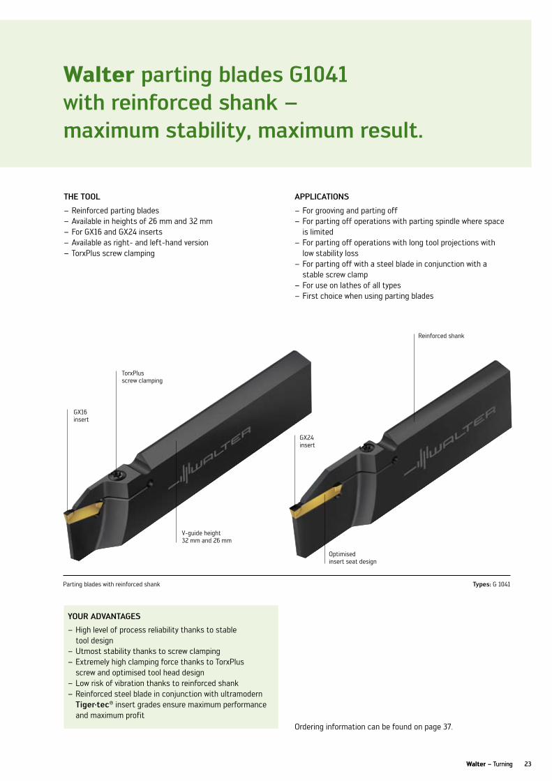
Walter parting blades g1041 with reinforced shank – maximum stability, maximum result.
Walter – Turning
Parting blades with reinforced shank Types: G 1041
ThE Tool
Reinforced parting blades –Available in heights of 26 mm and 32 mm –For GX16 and GX24 inserts –Available as right- and left-hand version –TorxPlus screw clamping –
aPPlicaTions
For grooving and parting off –For parting off operations with parting spindle where space –is limitedFor parting off operations with long tool projections with –low stability lossFor parting off with a steel blade in conjunction with a –stable screw clampFor use on lathes of all types –First choice when using parting blades –
your aDvanTagEs
High level of process reliability thanks to stable –tool designutmost stability thanks to screw clamping –Extremely high clamping force thanks to TorxPlus –screw and optimised tool head designlow risk of vibration thanks to reinforced shank –Reinforced steel blade in conjunction with ultramodern –Tiger·tec® insert grades ensure maximum performance and maximum profit
TorxPlus screw clamping
GX16insert
GX24insert
Reinforced shank
Optimised insert seat design
v-guide height32 mm and 26 mm
Ordering information can be found on page 37.

ORDER InFORMATIOn
24
L new addition to range
L Existing in range
iso indexable inserts cnMg / cngg / cnMM
Designationd
mml
mms
mmr
mm
P M K n S H
HC HC HC HC HW HC HW Bl BH
WPP
01
WPP
05
WPP
10
WPP
20
WPP
30
Ws
M10
Ws
M20
Ws
M30
Wa
M20
Wa
k10
Wa
k20
Wa
k30
Wx
n10
Wk
1
Ws
M10
Ws
M20
Ws
M30
Ws
10
Wcb
30
Wcb
50
CnMG 120404–nFT 12.7 12.9 4.76 0.4 L L L
CnMG 120408–nFT 12.7 12.9 4.76 0.8 L L L
CnGG 120404–nFT 12.7 12.9 4.76 0.4 L
CnGG 120408–nFT 12.7 12.9 4.76 0.8 L
CnMG 120408–nMT 12.7 12.9 4.76 0.8 L L L
CnMG 120412–nMT 12.7 12.9 4.76 1.2 L L L
CnMG 120408–nRT 15.875 16.1 6.35 0.8 L L L
CnMG 120412–nRT 15.875 16.1 6.35 1.2 L L L
CnMG 160612–nRT 19.05 19.3 6.35 1.2 L L L
CnMG 190616–nRT 19.05 19.3 6.35 1.6 L L L
CnMG 120404–nF4 12.7 12.9 4.76 0.4 L L L L L
CnMG 120408–nF4 12.7 12.9 4.76 0.8 L L L L L
CnMG 120412–nF4 12.7 12.9 4.76 1.2 L L L L L
CnMG 120404–nM4 12.7 12.9 4.76 0.4 L L L L L L L L L L L
CnMG 120408–nM4 12.7 12.9 4.76 0.8 L L L L L L L L L L L
CnMG 120412–nM4 12.7 12.9 4.76 1.2 L L L L L L L L L L L
CnMG 160608–nM4 15.875 16.1 6.35 0.8 L L L L L L L L L L L
CnMG 160612–nM4 15.875 16.1 6.35 1.2 L L L L L L L L L L L
CnMG 120408–nR4 12.7 12.9 4.76 0.8 L L L L L L L
CnMG 120412–nR4 12.7 12.9 4.76 1.2 L L L L L L L
CnMG 160608–nR4 15.875 16.1 6.35 0.8 L L L L L L L
CnMG 160612–nR4 15.875 16.1 6.35 1.2 L L L L L L L
CnMG 190612–nR4 19.05 19.3 6.35 1.2 L L L L L L L
CnMG 190616–nR4 19.05 19.3 6.35 1.6 L L L L L L L
CnMM 190612–nRR 19.05 19.3 6.35 1.2 L L L L
CnMM 190616–nRR 19.05 19.3 6.35 1.6 L L L L
CnMM 190624–nRR 19.05 19.3 6.35 2.4 L L L L
CnMM 250924–nRR 25.4 25.8 9.52 2.4 L L L L
CnMG 250924–nM6 25.4 25.8 9.52 2.4 L L

ORDER InFORMATIOn
25Walter – Turning
L new addition to range
L Existing in range
iso indexable inserts DnMg / Dngg
Designationd
mml
mms
mmr
mm
P M K n S H
HC HC HC HC HW HC HW Bl BH
WPP
01
WPP
05
WPP
10
WPP
20
WPP
30
Ws
M10
Ws
M20
Ws
M30
Wa
M20
Wa
k10
Wa
k20
Wa
k30
Wx
n10
Wk
1
Ws
M10
Ws
M20
Ws
M30
Ws
10
Wcb
30
Wcb
50
DnMG 150604–nFT 12.7 15.5 6.35 0.4 L L L
DnMG 150608–nFT 12.7 15.5 6.35 0.8 L L L
DnGG 150604–nFT 12.7 15.5 6.35 0.4 L
DnGG 150608–nFT 12.7 15.5 6.35 0.8 L
DnMG 150608–nMT 12.7 15.5 6.35 0.8 L L L
DnMG 150612–nMT 12.7 15.5 6.35 1.2 L L L
DnMG 110404–nF4 9.525 11.6 4.76 0.4 L L L L L
DnMG 110408–nF4 9.525 11.6 4.76 0.8 L L L L L
DnMG 150404–nF4 12.7 15.5 4.76 0.4 L L L L L
DnMG 150408–nF4 12.7 15.5 4.76 0.8 L L L L L
DnMG 150412–nF4 12.7 15.5 4.76 1.2 L L L L L
DnMG 150604–nF4 12.7 15.5 6.35 0.4 L L L L L
DnMG 150608–nF4 12.7 15.5 6.35 0.8 L L L L L
DnMG 150612–nF4 12.7 15.5 6.35 1.2 L L L L L
DnMG 110404–nM4 9.525 11.6 4.76 0.4 L L L L L L L
DnMG 110408–nM4 9.525 11.6 4.76 0.8 L L L L L L L
DnMG 150404–nM4 12.7 15.5 4.76 0.4 L L L L L L L
DnMG 150408–nM4 12.7 15.5 4.76 0.8 L L L L L L L
DnMG 150412–nM4 12.7 15.5 4.76 1.2 L L L L L L L
DnMG 150604–nM4 12.7 15.5 6.35 0.4 L L L L L L L
DnMG 150608–nM4 12.7 15.5 6.35 0.8 L L L L L L L
DnMG 150612–nM4 12.7 15.5 6.35 1.2 L L L L L L L
DnMG 150608–nR4 12.7 15.5 6.35 0.8 L L L L L L L
DnMG 150612–nR4 12.7 15.5 6.35 1.2 L L L L L L L
DnMG 150616-nM5 12.7 15.5 6.35 1.6 L L
ORDER InFORMATIOn
26
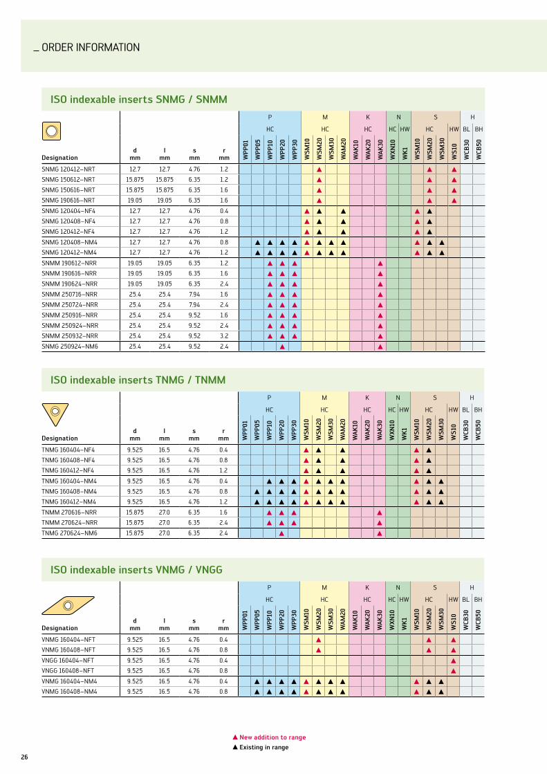
iso indexable inserts snMg / snMM
Designationd
mml
mms
mmr
mm
P M K n S H
HC HC HC HC HW HC HW Bl BH
WPP
01
WPP
05
WPP
10
WPP
20
WPP
30
Ws
M10
Ws
M20
Ws
M30
Wa
M20
Wa
k10
Wa
k20
Wa
k30
Wx
n10
Wk
1
Ws
M10
Ws
M20
Ws
M30
Ws
10
Wcb
30
Wcb
50
SnMG 120412–nRT 12.7 12.7 4.76 1.2 L L L
SnMG 150612–nRT 15.875 15.875 6.35 1.2 L L L
SnMG 150616–nRT 15.875 15.875 6.35 1.6 L L L
SnMG 190616–nRT 19.05 19.05 6.35 1.6 L L L
SnMG 120404–nF4 12.7 12.7 4.76 0.4 L L L L L
SnMG 120408–nF4 12.7 12.7 4.76 0.8 L L L L L
SnMG 120412–nF4 12.7 12.7 4.76 1.2 L L L L L
SnMG 120408–nM4 12.7 12.7 4.76 0.8 L L L L L L L L L L L
SnMG 120412–nM4 12.7 12.7 4.76 1.2 L L L L L L L L L L L
SnMM 190612–nRR 19.05 19.05 6.35 1.2 L L L L
SnMM 190616–nRR 19.05 19.05 6.35 1.6 L L L L
SnMM 190624–nRR 19.05 19.05 6.35 2.4 L L L L
SnMM 250716–nRR 25.4 25.4 7.94 1.6 L L L L
SnMM 250724–nRR 25.4 25.4 7.94 2.4 L L L L
SnMM 250916–nRR 25.4 25.4 9.52 1.6 L L L L
SnMM 250924–nRR 25.4 25.4 9.52 2.4 L L L L
SnMM 250932–nRR 25.4 25.4 9.52 3.2 L L L L
SnMG 250924–nM6 25.4 25.4 9.52 2.4 L L
iso indexable inserts TnMg / TnMM
Designationd
mml
mms
mmr
mm
P M K n S H
HC HC HC HC HW HC HW Bl BH
WPP
01
WPP
05
WPP
10
WPP
20
WPP
30
Ws
M10
Ws
M20
Ws
M30
Wa
M20
Wa
k10
Wa
k20
Wa
k30
Wx
n10
Wk
1
Ws
M10
Ws
M20
Ws
M30
Ws
10
Wcb
30
Wcb
50
TnMG 160404–nF4 9.525 16.5 4.76 0.4 L L L L L
TnMG 160408–nF4 9.525 16.5 4.76 0.8 L L L L L
TnMG 160412–nF4 9.525 16.5 4.76 1.2 L L L L L
TnMG 160404–nM4 9.525 16.5 4.76 0.4 L L L L L L L L L L
TnMG 160408–nM4 9.525 16.5 4.76 0.8 L L L L L L L L L L L
TnMG 160412–nM4 9.525 16.5 4.76 1.2 L L L L L L L L L L L
TnMM 270616–nRR 15.875 27.0 6.35 1.6 L L L L
TnMM 270624–nRR 15.875 27.0 6.35 2.4 L L L L
TnMG 270624–nM6 15.875 27.0 6.35 2.4 L L
iso indexable inserts vnMg / vngg
Designationd
mml
mms
mmr
mm
P M K n S H
HC HC HC HC HW HC HW Bl BH
WPP
01
WPP
05
WPP
10
WPP
20
WPP
30
Ws
M10
Ws
M20
Ws
M30
Wa
M20
Wa
k10
Wa
k20
Wa
k30
Wx
n10
Wk
1
Ws
M10
Ws
M20
Ws
M30
Ws
10
Wcb
30
Wcb
50
vnMG 160404–nFT 9.525 16.5 4.76 0.4 L L L
vnMG 160408–nFT 9.525 16.5 4.76 0.8 L L L
vnGG 160404–nFT 9.525 16.5 4.76 0.4 L
vnGG 160408–nFT 9.525 16.5 4.76 0.8 L
vnMG 160404–nM4 9.525 16.5 4.76 0.4 L L L L L L L L L L L
vnMG 160408–nM4 9.525 16.5 4.76 0.8 L L L L L L L L L L L
L new addition to range
L Existing in range

ORDER InFORMATIOn
27Walter – Turning
L new addition to range
L Existing in range
iso indexable inserts WnMg / WnMM
Designationd
mml
mms
mmr
mm
P M K n S H
HC HC HC HC HW HC HW Bl BH
WPP
01
WPP
05
WPP
10
WPP
20
WPP
30
Ws
M10
Ws
M20
Ws
M30
Wa
M20
Wa
k10
Wa
k20
Wa
k30
Wx
n10
Wk
1
Ws
M10
Ws
M20
Ws
M30
Ws
10
Wcb
30
Wcb
50
WnMG 060404–nF4 9.525 6.5 4.76 0.4 L L L L L
WnMG 060408–nF4 9.525 6.5 4.76 0.8 L L L L L
WnMG 080404–nF4 12.7 8.72 4.76 0.4 L L L L L
WnMG 080408–nF4 12.7 8.72 4.76 0.8 L L L L L
WnMG 080412–nF4 12.7 8.72 4.76 1.2 L L L L L
WnMG 060404–nM4 9.525 6.5 4.76 0.4 L L L L L L L L L L L
WnMG 060408–nM4 9.525 6.5 4.76 0.8 L L L L L L L L L L L
WnMG 060412–nM4 9.525 6.5 4.76 1.2 L L L L L L L L L L L
WnMG 080404–nM4 12.7 8.72 4.76 0.4 L L L L L L L L L L
WnMG 080408–nM4 12.7 8.72 4.76 0.8 L L L L L L L L L L L
WnMG 080412–nM4 12.7 8.72 4.76 1.2 L L L L L L L L L L L
WnMG 080408–nR4 12.7 8.72 4.76 0.8 L L L L L L L
WnMG 080412–nR4 12.7 8.72 4.76 1.2 L L L L L L L
WnMM 080412–nRF 12.7 8.72 4.76 1.2 L L
iso indexable inserts ccgT / ccMT
Designationd
mml
mms
mmr
mm
P M K n S H
HC HC HC HC HW HC Bl BH
WPP
01
WPP
10
WPP
20
WPP
30
Ws
M10
Ws
M20
Ws
M30
Wa
M20
Wa
k10
Wa
k20
Wa
k30
Wx
n10
Wk
1
Ws
M10
Ws
M20
Ws
M30
Wcb
30
Wcb
50
CCGT 060201–PF2 6.35 6.45 2.38 0.1 L L L L
CCGT 060202–PF2 6.35 6.45 2.38 0.2 L L L L
CCGT 060204–PF2 6.35 6.45 2.38 0.4 L L L L
CCGT 09T301–PF2 9.525 9.67 3.97 0.1 L L L L
CCGT 09T302–PF2 9.525 9.67 3.97 0.2 L L L L
CCGT 09T304–PF2 9.525 9.67 3.97 0.4 L L L L
CCGT 09T308–PF2 9.525 9.67 3.97 0.8 L L L L
CCMT 060202–PF4 6.35 6.45 2.38 0.2 L L L L L L L L L L
CCMT 060204–PF4 6.35 6.45 2.38 0.4 L L L L L L L L L L
CCMT 060208–PF4 6.35 6.45 2.38 0.8 L L L L L L L L L L
CCMT 09T302–PF4 9.525 9.67 3.97 0.2 L L L L L L L L L L
CCMT 09T304–PF4 9.525 9.67 3.97 0.4 L L L L L L L L L L
CCMT 09T308–PF4 9.525 9.67 3.97 0.8 L L L L L L L L L L
CCMT 060204–PM5 6.35 6.45 2.38 0.4 L L L L L L L L L L L L L
CCMT 060208–PM5 6.35 6.45 2.38 0.8 L L L L L L L L L L L L L
CCMT 09T304–PM5 9.525 9.67 3.97 0.4 L L L L L L L L L L L L L
CCMT 09T308–PM5 9.525 9.67 3.97 0.8 L L L L L L L L L L L L L
CCMT 120404–PM5 12.7 12.9 4.76 0.4 L L L L L L L L L L L L L
CCMT 120408–PM5 12.7 12.9 4.76 0.8 L L L L L L L L L L L L L
CCMT 120412–PM5 12.7 12.9 4.76 1.2 L L L L L L L L L L L L L
ORDER InFORMATIOn
28
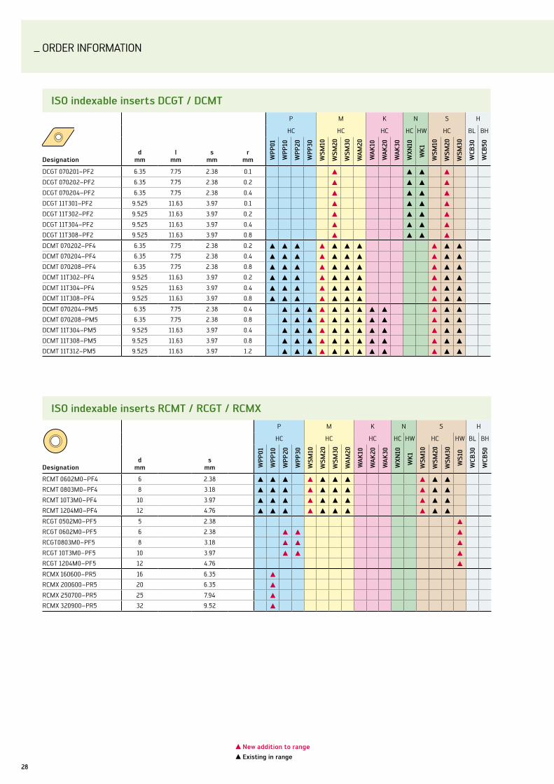
iso indexable inserts DcgT / DcMT
Designationd
mml
mms
mmr
mm
P M K n S H
HC HC HC HC HW HC Bl BH
WPP
01
WPP
10
WPP
20
WPP
30
Ws
M10
Ws
M20
Ws
M30
Wa
M20
Wa
k10
Wa
k20
Wa
k30
Wx
n10
Wk
1
Ws
M10
Ws
M20
Ws
M30
Wcb
30
Wcb
50
DCGT 070201–PF2 6.35 7.75 2.38 0.1 L L L L
DCGT 070202–PF2 6.35 7.75 2.38 0.2 L L L L
DCGT 070204–PF2 6.35 7.75 2.38 0.4 L L L L
DCGT 11T301–PF2 9.525 11.63 3.97 0.1 L L L L
DCGT 11T302–PF2 9.525 11.63 3.97 0.2 L L L L
DCGT 11T304–PF2 9.525 11.63 3.97 0.4 L L L L
DCGT 11T308–PF2 9.525 11.63 3.97 0.8 L L L L
DCMT 070202–PF4 6.35 7.75 2.38 0.2 L L L L L L L L L L
DCMT 070204–PF4 6.35 7.75 2.38 0.4 L L L L L L L L L L
DCMT 070208–PF4 6.35 7.75 2.38 0.8 L L L L L L L L L L
DCMT 11T302–PF4 9.525 11.63 3.97 0.2 L L L L L L L L L L
DCMT 11T304–PF4 9.525 11.63 3.97 0.4 L L L L L L L L L L
DCMT 11T308–PF4 9.525 11.63 3.97 0.8 L L L L L L L L L L
DCMT 070204–PM5 6.35 7.75 2.38 0.4 L L L L L L L L L L L L
DCMT 070208–PM5 6.35 7.75 2.38 0.8 L L L L L L L L L L L L
DCMT 11T304–PM5 9.525 11.63 3.97 0.4 L L L L L L L L L L L L
DCMT 11T308–PM5 9.525 11.63 3.97 0.8 L L L L L L L L L L L L
DCMT 11T312–PM5 9.525 11.63 3.97 1.2 L L L L L L L L L L L L
iso indexable inserts rcMT / rcgT / rcMx
Designationd
mms
mm
P M K n S H
HC HC HC HC HW HC HW Bl BH
WPP
01
WPP
10
WPP
20
WPP
30
Ws
M10
Ws
M20
Ws
M30
Wa
M20
Wa
k10
Wa
k20
Wa
k30
Wx
n10
Wk
1
Ws
M10
Ws
M20
Ws
M30
Ws
10
Wcb
30
Wcb
50RCMT 0602M0–PF4 6 2.38 L L L L L L L L L L
RCMT 0803M0–PF4 8 3.18 L L L L L L L L L L
RCMT 10T3M0–PF4 10 3.97 L L L L L L L L L L
RCMT 1204M0–PF4 12 4.76 L L L L L L L L L L
RCGT 0502M0–PF5 5 2.38 L
RCGT 0602M0–PF5 6 2.38 L L L
RCGT0803M0–PF5 8 3.18 L L L
RCGT 10T3M0–PF5 10 3.97 L L L
RCGT 1204M0–PF5 12 4.76 L
RCMX 160600–PR5 16 6.35 L
RCMX 200600–PR5 20 6.35 L
RCMX 250700–PR5 25 7.94 L
RCMX 320900–PR5 32 9.52 L
L new addition to range
L Existing in range

ORDER InFORMATIOn
29Walter – Turning
L new addition to range
L Existing in range
iso indexable inserts scgT / scMT
Designationd
mml
mms
mmr
mm
P M K n S H
HC HC HC HC HW HC Bl BH
WPP
01
WPP
10
WPP
20
WPP
30
Ws
M10
Ws
M20
Ws
M30
Wa
M20
Wa
k10
Wa
k20
Wa
k30
Wx
n10
Wk
1
Ws
M10
Ws
M20
Ws
M30
Wcb
30
Wcb
50
SCGT 09T304-PF2 9.525 9.525 3.97 0.4 L L
SCGT 09T308-PF2 9.525 9.525 3.97 0.8 L L
SCGT 120408-PF2 12.7 12.7 4.76 0.8 L L
SCMT 120412–PF4 12.7 12.7 4.76 1.2 L L
SCMT 09T304–PM5 9.525 9.525 3.97 0.4 L L L L L L L L L L L L L
SCMT 09T308–PM5 9.525 9.525 3.97 0.8 L L L L L L L L L L L L L
SCMT 120404–PM5 12.7 12.7 4.76 0.4 L L L L L L L L L L L L L
SCMT 120408–PM5 12.7 12.7 4.76 0.8 L L L L L L L L L L L L L
SCMT 120412–PM5 12.7 12.7 4.76 1.2 L L L L L L L L L L L L L
iso indexable inserts TcgT / TcMT
Designationd
mml
mms
mmr
mm
P M K n S
HC HC HC HC HW HC
WPP
01
WPP
10
WPP
20
WPP
30
Ws
M10
Ws
M20
Ws
M21
Ws
M30
Wa
M20
Wa
k10
Wa
k20
Wa
k30
Wx
n10
Wk
1
Ws
M10
Ws
M20
Ws
M21
Ws
M30
TCGT 06T101–PF2 3.97 6.0 1.98 0.1 L L L L
TCGT 06T102–PF2 3.97 6.0 1.98 0.2 L L L L
TCGT 06T104–PF2 3.97 6.0 1.98 0.4 L L L L
TCGT 090201–PF2 5.56 9.0 2.38 0.1 L L L L
TCGT 090202–PF2 5.56 9.0 2.38 0.2 L L L L
TCGT 090204–PF2 5.56 9.0 2.38 0.4 L L L L
TCGT 110201–PF2 6.35 11.0 2.38 0.1 L L L L
TCGT 110202–PF2 6.35 11.0 2.38 0.2 L L L L
TCGT 110204–PF2 6.35 11.0 2.38 0.4 L L L L
TCGT 16T301–PF2 9.525 16.5 3.97 0.1 L L L L
TCGT 16T302–PF2 9.525 16.5 3.97 0.2 L L L L
TCGT 16T304–PF2 9.525 16.5 3.97 0.4 L L L L
TCGT 16T308–PF2 9.525 16.5 3.97 0.8 L L L L
TCMT 06T102–PF4 3.97 6.0 1.98 0.2 L L L
TCMT 06T104–PF4 3.97 6.0 1.98 0.4 L L L
TCMT 090202–PF4 5.56 9.0 2.38 0.2 L L L L L L L L L
TCMT 090204–PF4 5.56 9.0 2.38 0.4 L L L L L L L L L
TCMT 090208–PF4 5.56 9.0 2.38 0.8 L L L L L L L L L
TCMT 110202–PF4 6.35 11.0 2.38 0.2 L L L L L L L L L L
TCMT 110204–PF4 6.35 11.0 2.38 0.4 L L L L L L L L L L
TCMT 110208–PF4 6.35 11.0 2.38 0.8 L L L L L L L L L L
TCMT 110204–PM5 6.35 11.0 2.38 0.4 L L L L L L L L L L L L L
TCMT 110208–PM5 6.35 11.0 2.38 0.8 L L L L L L L L L L L L L
TCMT 16T304–PM5 9.525 16.5 3.97 0.4 L L L L L L L L L L L L L
TCMT 16T308–PM5 9.525 16.5 3.97 0.8 L L L L L L L L L L L L L
TCMT 16T312–PM5 9.525 16.5 3.97 1.2 L L L L L L L L L L L L L

ORDER InFORMATIOn
30
L new addition to range
L Existing in range
iso indexable inserts vb . . / vc . .
Designationd
mml
mms
mmr
mm
P M K n S H
HC HC HC HC HW HC Bl BH
WPP
01
WPP
10
WPP
20
WPP
30
Ws
M10
Ws
M20
Ws
M30
Wa
M20
Wa
k10
Wa
k20
Wa
k30
Wx
n10
Wk
1
Ws
M10
Ws
M20
Ws
M30
Wcb
30
Wcb
50
vCGT 110301–PF2 6.35 11.0 3.18 0.1 L L L L
vCGT 110302–PF2 6.35 11.0 3.18 0.2 L L L L
vCGT 110304–PF2 6.35 11.0 3.18 0.4 L L L L
vCGT 160402–PF2 9.525 16.6 4.76 0.2 L L L L
vCGT 160404–PF2 9.525 16.6 4.76 0.4 L L L L
vCGT 160408–PF2 9.525 16.6 4.76 0.8 L L L L
vCMT 110302–PF4 6.35 11.0 3.18 0.2 L L L L L L L L L L
vCMT 110304–PF4 6.35 11.0 3.18 0.4 L L L L L L L L L L
vCMT 160402–PF4 9.525 16.6 4.76 0.2 L L L L L L L L L L
vCMT 160404–PF4 9.525 16.6 4.76 0.4 L L L L L L L L L L
vCMT 160408–PF4 9.525 16.6 4.76 0.8 L L L L L L L L L L
vBMT 110304–PS5 6.35 11.0 3.18 0.4 L L L L L L L L L L L
vBMT 110308–PS5 6.35 11.0 3.18 0.8 L L L L L L L L L L L
vBMT 160404–PS5 9.525 16.6 4.76 0.4 L L L L L L L L L L L
vBMT 160406–PS5 9.525 16.6 4.76 0.6 L L L L L L L L L L L
vBMT 160408–PS5 9.525 16.6 4.76 0.8 L L L L L L L L L L L
vBMT 160412–PS5 9.525 16.6 4.76 1.2 L L L L L L L L L L L
vCMT 110304–PM5 6.35 11.0 3.18 0.4 L L L L L L L L L L L L
vCMT 110308–PM5 6.35 11.0 3.18 0.8 L L L L L L L L L L L L
vCMT 160404–PM5 9.525 16.6 4.76 0.4 L L L L L L L L L L L L
vCMT 160406–PM5 9.525 16.6 4.76 0.6 L L L L L L L L L L L L
vCMT 160408–PM5 9.525 16.6 4.76 0.8 L L L L L L L L L L L L
vCMT 160412–PM5 9.525 16.6 4.76 1.2 L L L L L L L L L L L L

ORDER InFORMATIOn
31Walter – Turning
Walter cut inserts gx…
gx24 inserts with 0.8 mm corner radius P M
HC HC
Designations
mml
mmr
mm WPP
23
Ws
P43
Ws
M33
GX24-3E400n080-uF4 4 24 0.8 L L
GX24-3E500n080-uF4 5 24 0.8 L L
GX24-4E600n080-uF4 6 24 0.8 L L
gx single-sided inserts for parting off
GX16-1F200n020-CE4 2 16.6 0.2 L L
GX16-1F250n020-CE4 2.5 16.6 0.2 L L
GX24-2F300n020-CE4 3 24 0.2 L L
GX24-3F400n030-CE4 4 24 0.3 L L
GX16-1F200n020-CF6 2 16.6 0.2 L L
GX16-1F250n020-CF6 2.5 16.6 0.2 L L
GX24-2F300n020-CF6 3 24 0.2 L L
L new addition to range
L Existing in range
Walter cut inserts gx…
Designationl
mms
mmr
mm
P M K S
HC HC HC HC
WPP23 WsM33 WsP43 WsM33 WsP43 WPP23 WsM33 WsP43
GX16-1E200n020–CE4 16.6 2.0 0.2 L L L L L L
GX24-2E400R6–CE4 24.6 3.0 0.2 L L L L L L L L
GX24-3E400R6–CE4 24.6 4.0 0.2 L L L L L L L L
GX24-2E400l6–CE4 24.6 3.0 0.2 L L L L L L L L
GX24-3E400l6–CE4 24.6 4.0 0.2 L L L L L L L L
GX24-2E300n020–CF6 24.0 3.0 0.2 L L L L L L
GX24-2E300R6–CF6 24.6 3.0 0.2 L L L L L L
GX24-2E300l6–CF6 24.6 3.0 0.2 L L L L L L
NEW2010
Walter nTs indexable inserts for threading
60° partial profile inserts P M
HC HC
Designationl
mm
mm
T/inchr
mm
x
mm
y
mm Wx
P20
Wx
M20
nTS-IR-16 AG60 16 0.5-3 48-8 0.05 1.2 1.7 L L
nTS-Il-16 AG60 16 0.5-3 48-8 0.05 1.2 1.7 L L
nTS-ER-16 AG60 16 0.5-3 48-8 0.08 1.2 1.7 L L
nTS-El-16 AG60 16 0.5-3 48-8 0.08 1.2 1.7 L L
nTS-IR-16 G60 16 1.75-3 14-8 0.16 1.2 1.7 L L
nTS-Il-16 G60 16 1.75-3 14-8 0.16 1.2 1.7 L L
nTS-ER-16 G60 16 1.75-3 14-8 0.27 1.2 1.7 L L
nTS-El-16 G60 16 1.75-3 14-8 0.27 1.2 1.7 L L
nTS-ER-22 n60 22 3.5-5 7-5 0.53 1.7 2.5 L L
nTS-El-22 n60 22 3.5-5 7-5 0.53 1.7 2.5 L L
nTS-IR-22 n60 22 3.5-5 7-5 0.3 1.7 2.5 L L
nTS-Il-22 n60 22 3.5-5 7-5 0.3 1.7 2.5 L L
lead
NEW2010

ORDER InFORMATIOn
32
Walter Turn Toolholder – rigid clamping system
Designationh=h1 mm
bmm
f mm
l1 mm
l2 mm s n
clamping torque
nm Type
DClnR/l1616H12 12 16 16 20 100 32.2 –6° –6° 95° 3.9Cn . . 1204 . .DCBnR/l2525M12 12 25 25 22 150 34.6 –6° –6° 75° 3.9
DCBnR/l3225P12 12 32 25 22 170 34.6 –6° –6° 75° 3.9
DCBnR/l2525M16 16 25 25 22 150 41.5 –6° –6° 75° 6.4Cn . . 1606 . .
DCBnR/l3232P16 16 32 32 22 170 41.6 –6° –6° 75° 6.4
DCBnR/l3232P19 19 32 32 27 170 46.1 –6° –6° 75° 6.4 Cn . . 1906 . .
DCKnR/l2525M12 12 25 25 32 150 21.1 –6° –6° 75° 3.9 Cn . . 1204 . .DCKnR/l3225P12 12 32 25 32 170 21.1 –6° –6° 75° 3.9
DCKnR/l3232P16 16 32 32 40 170 26 –6° –6° 75° 6.4 Cn . . 1606 . .
Designationamin mm
dg7 mm
f mm
l1 mm
l3 mm s n
clamping torque
nm Type
Dvvnn2020K16 16 20 20 10.6 125 47.8 –4° –13° 72.5° 3.0
vn . . 1604 . .Dvvnn2525M16 16 25 25 13.1 150 47.8 –4° –13° 72.5° 3.0
Dvvnn3225P16 16 32 25 13.1 170 47.8 –4° –13° 72.5° 3.0
shim for Walter Turn lever type clamp toolholders
Designation shim for
AP192–Cn2524 Cn . . 250924 . . R ≤ 2.4
AP191–Sn250924* Sn . . 250924 . . R ≤ 2.4
* Walter Turn lever type clamps fitted as standard with shim AP144–Sn2524 are designed for installation of Sn . . 2507 . . indexable inserts. Fitting shim AP 191–Sn240924 enables Sn . . 2509 . . indexable inserts to be clamped in the same tool.
★ new addition to range
Walter Turn Toolholder – lever type clamping
Designationh=h1 mm
b mm
f mm
l1 mm
l2 mm s n Type
PCln R/l 1616 H12 12 16 16 20 100 27.2 -6 -6 95 Cn . . 1204 . .
PCln R/l 4040 S25 25 40 40 50 250 50.0 -6 -6 95 Cn . . 2509 . .
Designationh=h1 mm
b mm
f mm
l1 mm
l2 mm s n Type
★ PRGCR/l 3232P20 20 32 32 40 170 0 0 RC . . 2006 . .
★ PRDCn3232P20 20 32 32 26 180 40 0 0 RC . . 2006 . .
★ PRDCn5050u32 32 50 50 41 350 55 0 0 RC . . 3209 . .
Designationh=h1 mm
b mm
f mm
l1 mm
l2 mm s n Type
★ PSDnn4040S25 25 40 40 21 250 48.8 -6 -6 45 Sn . . 2507 . .
Designationh=h1 mm
b mm
f mm
l1 mm
l2 mm s n Type
★ PTGnR/l 1616H16 16 16 16 20 100 20.2 -6 -6 91 Tn . . 1604 . .

ORDER InFORMATIOn
33Walter – Turning
★ new addition to range
Walter capto™ toolholder – rigid clamping system
Designationdmmm
f mm
l1 mm s n
clamping torquenm Type
★ C8-DClnR/l-55080-12 12 80 55 80 -6 -6 95 3.9 Cn . . 1204 . .
★ C8-DClnR/l-55080-16 16 80 55 80 -6 -6 95 6.4 Cn . . 1606 . .
★ C8-DClnR/l-55080-19 19 80 55 80 -6 -6 95 6.4 Cn . . 1906 . .
Designationdmmm
f mm
l1 mm s n
clamping torquenm Type
★ C8-DDJnR/l-55080-15 15 80 55 80 -7 -6 93 3.9 Dn . . 1506 . .
★ C4-DDunR/l-27050-15 15 40 27 50 -7 -6 93 3.9 Dn . . 1506 . .
★ C5-DDunR/l-35060-15 15 50 35 60 -7 -6 93 3.9 Dn . . 1506 . .
★ C6-DDunR/l-45065-15 15 63 45 65 -7 -6 93 3.9 Dn . . 1506 . .
★ C8-DDunR/l-55080-15 15 80 55 80 -7 -6 93 3.9 Dn . . 1506 . .
Designationdmmm
f mm
l1 mm s n
clamping torquenm Type
★ C4-DSDnn-00050-12 12 40 0.3 50 -6 -6 45 3.9 Sn . . 1204 . .
★ C5-DSDnn-00060-12 12 50 0.3 60 -6 -6 45 3.9 Sn . . 1204 . .
★ C6-DSDnn-00065-12 12 63 0.3 65 -6 -6 45 3.9 Sn . . 1204 . .
★ C6-DSDnn-00070-19 19 63 0.5 70 -6 -6 45 6.4 Sn . . 1906 . .
★ C8-DSDnn-00080-25 25 80 1 80 -6 -6 45 9.5 Sn . . 2507 . .
★ C8-DSRnR/l-45080-19 19 80 45 80 -6 -6 75 3.4 Sn . . 1906 . .
★ C8-DSRnR/l-45080-25 25 80 45 80 -6 -6 75 9.5 Sn . . 2507 . .
★ C8-DSKnR/l-55080-19 19 80 55 80 -6 -6 75 6.4 Sn . . 1906 . .
Designationdmmm
f mm
l1 mm s n
clamping torquenm Type
★ C8-DvJnR/l-55080-16 16 80 55 80 -13 -4 93 1.7 vn . . 1604 . .
NEW2010

ORDER InFORMATIOn
34
★ new addition to range
Walter capto™ toolholder – lever type clamping
Designationdmmm
f mm
l1 mm
l2 mm s n Type
★ C8-PClnR/l-55080-12 12 80 55 80 -6 -6 95 Cn . . 1204. .
★ C8-PClnR/l-55080-16 16 80 55 80 -6 -6 95 Cn . . 1606. .
★ C8-PClnR/l-55080-19 19 80 55 80 -6 -6 95 Cn . . 1906 . .
★ C8-PClnR/l-55080-25 25 80 55 80 -6 -6 95 Cn . . 2509 . .
Designationdmmm
f mm
l1 mm
l2 mm s n Type
★ C8-PSRnR/l-45080-19 19 80 45 80 -6 -6 75 Sn . . 1906 . .
★ C8-PSRnR/l-45080-25 25 80 45 80 -6 -6 75 Sn . . 2507 . .
★ C8-PSKnR/l-55080-19 19 80 55 80 -6 -6 75 Sn . . 1906 . .
Designationdmmm
f mm
l1 mm
l2 mm s n Type
★ C6-PRDCn-00065-25 25 63 12.5 65 40 0 0 RC . . 2507 . .
★ C8-PRSCR/l-55080-20 20 80 55 80 0 0 RC . . 2006 . .
★ C8-PRSCR/l-55080-25 25 80 55 80 0 0 RC . . 2507 . .
NEW2010
Walter Turn 45°
Designationdmmm
f mm
l1 mm s n
clamping torquenm Type
★ C8-DCMnn-00150-16 16 80 0 150 -6 -6 95 6.4 Cn . . 1606 . .
Designationdmmm
f mm
l1 mm s n
clamping torquenm
★ C8-DDMnl-00160-15 15 80 0 160 -6 -5 93 3.9 Dn . . 1506 . .
Designationdmmm
f mm
l1 mm s n
clamping torquenm Type
★ C8-DvMnl-00160-16 16 80 0 160 -14 -4 95 1.7 vn . . 1604 . .
NEW2010
ORDER InFORMATIOn
35Walter – Turning
★ new addition to range
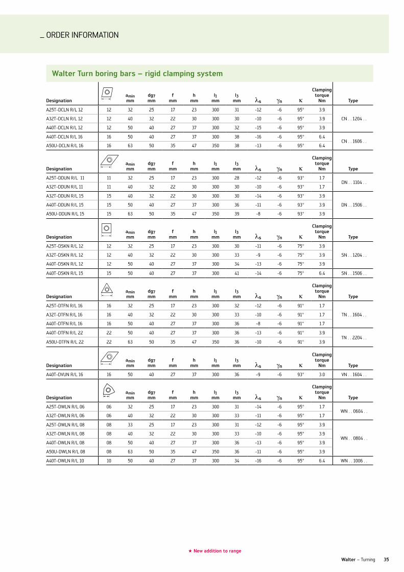
Walter Turn boring bars – rigid clamping system
Designationamin mm
dg7 mm
f mm
h mm
l1 mm
l3 mm s n
clamping torque
nm Type
A25T-DCln R/l 12 12 32 25 17 23 300 31 -12 -6 95° 3.9
Cn . . 1204 . . A32T-DCln R/l 12 12 40 32 22 30 300 30 -10 -6 95° 3.9
A40T-DCln R/l 12 12 50 40 27 37 300 32 -15 -6 95° 3.9
A40T-DCln R/l 16 16 50 40 27 37 300 38 -16 -6 95° 6.4Cn . . 1606 . .
A50u-DCln R/l 16 16 63 50 35 47 350 38 -13 -6 95° 6.4
Designationamin mm
dg7 mm
f mm
h mm
l1 mm
l3 mm s n
clamping torque
nm Type
A25T-DDun R/l 11 11 32 25 17 23 300 28 -12 -6 93° 1.7Dn . . 1104 . .
A32T-DDun R/l 11 11 40 32 22 30 300 30 -10 -6 93° 1.7
A32T-DDun R/l 15 15 40 32 22 30 300 30 -14 -6 93° 3.9
Dn . . 1506 . . A40T-DDun R/l 15 15 50 40 27 37 300 36 -11 -6 93° 3.9
A50u-DDun R/l 15 15 63 50 35 47 350 39 -8 -6 93° 3.9
Designationamin mm
dg7 mm
f mm
h mm
l1 mm
l3 mm s n
clamping torque
nm Type
A25T-DSKn R/l 12 12 32 25 17 23 300 30 -11 -6 75° 3.9
Sn . . 1204 . . A32T-DSKn R/l 12 12 40 32 22 30 300 33 -9 -6 75° 3.9
A40T-DSKn R/l 12 12 50 40 27 37 300 34 -13 -6 75° 3.9
A40T-DSKn R/l 15 15 50 40 27 37 300 41 -14 -6 75° 6.4 Sn . . 1506 . .
Designationamin mm
dg7 mm
f mm
h mm
l1 mm
l3 mm s n
clamping torque
nm Type
A25T-DTFn R/l 16 16 32 25 17 23 300 32 -12 -6 91° 1.7
Tn . . 1604 . . A32T-DTFn R/l 16 16 40 32 22 30 300 33 -10 -6 91° 1.7
A40T-DTFn R/l 16 16 50 40 27 37 300 36 -8 -6 91° 1.7
A40T-DTFn R/l 22 22 50 40 27 37 300 36 -13 -6 91° 3.9Tn . . 2204 . .
A50u-DTFn R/l 22 22 63 50 35 47 350 36 -10 -6 91° 3.9
Designationamin mm
dg7 mm
f mm
h mm
l1 mm
l3 mm s n
clamping torque
nm Type
A40T-Dvun R/l 16 16 50 40 27 37 300 36 -9 -6 93° 3.0 vn . . 1604 . .
Designationamin mm
dg7 mm
f mm
h mm
l1 mm
l3 mm s n
clamping torque
nm Type
A25T-DWln R/l 06 06 32 25 17 23 300 31 -14 -6 95° 1.7Wn . . 0604 . .
A32T-DWln R/l 06 06 40 32 22 30 300 33 -11 -6 95° 1.7
A25T-DWln R/l 08 08 33 25 17 23 300 31 -12 -6 95° 3.9
Wn . . 0804 . . A32T-DWln R/l 08 08 40 32 22 30 300 33 -10 -6 95° 3.9
A40T-DWln R/l 08 08 50 40 27 37 300 36 -13 -6 95° 3.9
A50u-DWln R/l 08 08 63 50 35 47 350 36 -11 -6 95° 3.9
A40T-DWln R/l 10 10 50 40 27 37 300 34 -16 -6 95° 6.4 Wn . . 1006 . .

ORDER InFORMATIOn
36
★ new addition to range
Walter Turn boring bars – screw clamping, positive basic shape
Designationaminmm
dg7 mm
f mm
h mm
l1 mm s n
clamping torque
nminsert screw Type
★ A08H-SClCR/l 06 06 10.0 08 5.0 7.0 100.0 -14° 0° 95° 0.9 FS2066 CC..0602..
★ A08H-SClCR/l 06-R 06 10.0 08 5.0 100.0 -14° 0° 95° 0.9 FS2066 CC..0602..
★ A10K-SClCR/l 06 06 12.0 10 6.0 9.0 125.0 -11° 0° 95° 0.9 FS2061 CC..0602..
★ A10K-SClCR/l 06-R 06 12.0 10 6.0 125.0 -11° 0° 95° 0.9 FS2061 CC..0602..
★ E08K-SClCR/l 06-R 06 10.0 08 5.0 125 -10° 0° 95° 0.9 FS2066 CC..0602..
★ E10M-SClCR/l 06-R 06 12.0 10 6.0 150 -7° 0° 95° 0.9 FS2061 CC..0602..
★ E12Q-SClCR/l06-R 06 16.0 12 9.0 180 -3° 0° 95° 0.9 FS2061 CC..0602..
★ E16R-SClCR/l 09-R 09 20.0 16 11.0 200 0° 0° 95° 3.0 FS2062 CC..09T3..
Designationaminmm
dg7 mm
f mm
h mm
l1 mm s n
clamping torque
nminsert screw Type
★ A10K-SDuCR/ l07 07 13.0 10 7.0 9.0 125.0 -9° 0° 93° 0.9 FS2061 DC..0702..
★ A10K-SDuCR/l 07-R 07 15.0 10 9.0 125.0 -7° 0° 93° 0.9 FS2061 DC..0702..
★ A16R-SDuCR/l 07-X 07 22.0 16 13.0 15.0 200.0 -3° 0° 93° 0.9 FS2061 DC..0702..
★ A20S-SDuCR/l 07-X 07 27.0 20 15.0 18.0 250.0 -2° 0° 93° 0.9 FS2061 DC..0702..
★ A25T-SDuCR/l 07-X 07 33.0 25 18.0 23.0 300.0 0° 0° 93° 0.9 FS2061 DC..0702..
★ A32T-SDuCR/l 11-X 11 40.0 32 22.0 30.0 300.0 -7° 0° 93° 3.0 FS2060 DC..11T3..
★ E10M-SDuCR/l 07-R 07 15.0 10 9.0 150.0 -5° 0° 93° 0.9 FS2061 DC..0702..
★ E12Q-SDuCR/l 07-R 07 18.0 12 11.0 180.0 -5° 0° 93° 0.9 FS2061 DC..0702..
★ E16R-SDuCR/l 07-R 07 22.0 16 13.0 200.0 -5° 0° 93° 0.9 FS2061 DC..0702..
Designationaminmm
dg7 mm
f mm
h mm
l1 mm s n
clamping torque
nminsert screw Type
★ A06F-STFCR/l 06 06 8.5 06 4.5 5.0 80.0 -12° 0° 91° 0.6 FS2147 TC..06T1..
★ A06F-STFCR/l 06-R 06 8.5 06 4.5 80.0 -10° 0° 91° 0.6 FS2147 TC..06T1..
★ A08H-STFCR/l 06 06 11.0 08 5.9 7.0 100.0 -10° 0° 91° 0.6 FS2148 TC..06T1..
★ A08H-STFCR/l 06-R 06 11.0 08 5.9 100.0 -6° 0° 91° 0.6 FS2148 TC..06T1..
★ A10K-STFCR/l 09 09 13.0 10 7.0 9.0 125.0 -9° 0° 91° 0.9 FS2149 TC..0902..
★ A10K-STFCR/l 09-R 09 13.0 10 7.0 125.0 -8° 0° 91° 0.9 FS2149 TC..0902..
★ E06H-STFCR/l 06-R 06 8.5 06 4.5 100.0 -10° 0° 91° 0.6 FS2147 TC..06T1..
★ E08K-STFCR/l 06-R 06 11.0 08 5.9 125.0 -10° 0° 91° 0.6 FS2148 TC..06T1..
★ E10M-STFCR/l 09-R 09 13.0 10 7.0 150.0 -8° 0° 91° 0.9 FS2149 CC..09T3..
★ E12Q-STFCR/l 09-R 09 16.0 12 9.0 180.0 -6° 0° 91° 0.9 FS2149 CC..09T3..
★ E16R-STFCR/l 11-R 11 20.0 16 11.0 200.0 -5° 0° 91° 1.0 FS2061 TC..1102..
Designationaminmm
dg7 mm
f mm
h mm
l1 mm s n
clamping torque
nminsert screw Type
★ A10K-SWlCR/l 04 04 13 10 7.0 9.0 125.0 -10° 0° 95° 0.9 FS2067 WC..0402..
★ A12M-SWlCR/l 04 04 16 12 9.0 11.0 150.0 -7° 0° 95° 0.9 FS2067 WC..0402..
★ A16R-SWlCR/l 04 04 20 16 11.0 15.0 200.0 -5° 0° 95° 0.9 FS2067 WC..0402..
★ A20S-SWlCR/l 06 06 20 20 13.0 18.0 250.0 -6° 0° 95° 3.0 FS2062 WC..06T3..
NEW2010
ORDER InFORMATIOn
37Walter – Turning
★ new addition to range
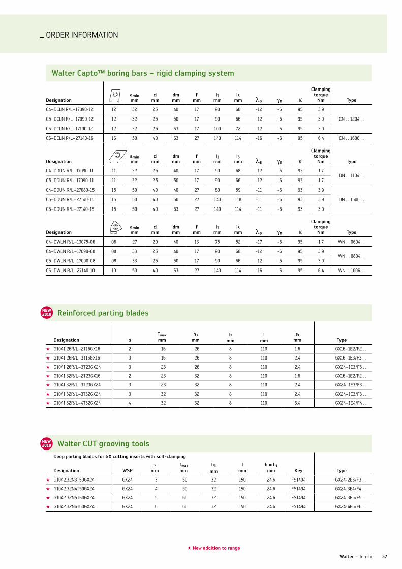
reinforced parting blades
Designation sTmax
mmh3
mmb
mml
mms1
mm Type
★ G1041.26R/l–2T16GX16 2 16 26 8 110 1.6 GX16–1E2/F2 . .
★ G1041.26R/l–3T16GX16 3 16 26 8 110 2.4 GX16–1E3/F3 . .
★ G1041.26R/l–3T23GX24 3 23 26 8 110 2.4 GX24–1E3/F3 . .
★ G1041.32R/l–2T23GX16 2 23 32 8 110 1.6 GX16–1E2/F2 . .
★ G1041.32R/l–3T23GX24 3 23 32 8 110 2.4 GX24–1E3/F3 . .
★ G1041.32R/l–3T32GX24 3 32 32 8 110 2.4 GX24–1E3/F3 . .
★ G1041.32R/l–4T32GX24 4 32 32 8 110 3.4 GX24–1E4/F4 . .
Walter cuT grooving toolsDeep parting blades for gx cutting inserts with self-clamping
Designation WsPs
mmTmax
mmh3
mml
mmh = h1
mm key Type
★ G1042.32n3T50GX24 GX24 3 50 32 150 24.6 FS1494 GX24-2E3/F3 . .
★ G1042.32n4T50GX24 GX24 4 50 32 150 24.6 FS1494 GX24-3E4/F4 . .
★ G1042.32n5T60GX24 GX24 5 60 32 150 24.6 FS1494 GX24-3E5/F5 . .
★ G1042.32n6T60GX24 GX24 6 60 32 150 24.6 FS1494 GX24-4E6/F6 . .
NEW2010
NEW2010
Walter capto™ boring bars – rigid clamping system
Designationamin mm
dmm
dm mm
f mm
l1 mm
l3 mm s n
clamping torque
nm Type
C4–DCln R/l–17090-12 12 32 25 40 17 90 68 -12 -6 95 3.9
Cn . . 1204 . . C5–DCln R/l–17090-12 12 32 25 50 17 90 66 -12 -6 95 3.9
C6–DCln R/l–17100-12 12 32 25 63 17 100 72 -12 -6 95 3.9
C6–DCln R/l–27140-16 16 50 40 63 27 140 114 -16 -6 95 6.4 Cn . . 1606 . .
Designationamin mm
dmm
dm mm
f mm
l1 mm
l3 mm s n
clamping torque
nm Type
C4–DDun R/l–17090-11 11 32 25 40 17 90 68 -12 -6 93 1.7Dn . . 1104 . .
C5–DDun R/l–17090-11 11 32 25 50 17 90 66 -12 -6 93 1.7
C4–DDun R/l–27080-15 15 50 40 40 27 80 59 -11 -6 93 3.9
Dn . . 1506 . . C5–DDun R/l–27140-15 15 50 40 50 27 140 118 -11 -6 93 3.9
C6–DDun R/l–27140-15 15 50 40 63 27 140 114 -11 -6 93 3.9
Designationamin mm
dmm
dm mm
f mm
l1 mm
l3 mm s n
clamping torque
nm Type
C4–DWln R/l–13075-06 06 27 20 40 13 75 52 -17 -6 95 1.7 Wn . . 0604 . .
C4–DWln R/l–17090-08 08 33 25 40 17 90 68 -12 -6 95 3.9Wn . . 0804 . .
C5–DWln R/l–17090-08 08 33 25 50 17 90 66 -12 -6 95 3.9
C6–DWln R/l–27140-10 10 50 40 63 27 140 114 -16 -6 95 6.4 Wn . . 1006 . .

ORDER InFORMATIOn
38
★ new addition to range
Extensions / reducers – Walter capto™
Designation
sizeof
mach.sizetool
D1mm
D2mm
x1mm
x2mm kg
★ C8-391.01-80 100A C8 C8 80 80 100 3.6
★ C8-391.01-80 125A C8 C8 80 80 125 4.6
★ C8-391.01-80 065 C8 C8 80 80 65 2.3
★ C8-391.02-50 045 C8 C5 80 50 45 10 1.8
★ C8-391.02-63 055 C8 C6 80 63 55 20 2
★ C8-391.02-63 080A C8 C6 80 63 80 53.1 2.5
★ C8-391.02-63 120A C8 C6 80 63 120 12 4
★ C8-391.02-50 080A C8 C5 80 50 80 49.3 2.2
Weldon shank adaptors – Walter capto™
Designation sizeD1
mmD2mm
D3mm
x1mm
x2mm
x3mm kg
★ C8-391.20-16 070 C8 80 16 48 70 32.5 46 2.3
★ C8-391.20-20 070 C8 80 20 52 70 35 45 2.4
★ C8-391.20-25 080 C8 80 25 65 80 53.7 56 2.3
★ C8-391.20-32 080 C8 80 32 72 80 53.7 56 2.9
★ C8-391.20-40 110 C8 80 40 90 110 79 80 4.5
NEW2010
hsk basic holder – Walter capto™
Designation sizehsk size
D1mm
D2mm
x1mm
x2mm kg
★ C3-390.410-63 075C C3 63– A 63 32 75 49 1.4
★ C4-390.410-100 090A C4 100– A 100 40 90 61 4.1
★ C4-390.410-63 080C C4 63– A 63 40 80 54 1.6
★ C5-390.410-100 100A C5 100– A 100 50 100 71 3
★ C5-390.410-63 090C C5 63– A 63 50 90 64 1.5
★ C6-390.410-100 110A C6 100– A 100 63 110 81 3.6
★ C8-390.410-100 120A C8 100– A 100 80 120 91 4.7
NEW2010
NEW2010
boring bar adaptor ak600
DesignationD1
mmD2mm
l1 mm
l mm
★ AK600.25.061.06 25 6 5 61
★ AK600.25.061.08 25 8 5 61
★ AK600.32.085.06 32 6 5 85
★ AK600.32.085.08 32 8 5 85
★ AK600.40.105.06 40 6 5 105
★ AK600.40.105.08 40 8 5 105
coolant adaptor k600
Designationdg7mm
d1mm
l mm
★ K600.06.25.054 6 5.4 25
★ K600.08.28.066 8 6.6 28
★ K600.25.44.137 25 13.7 44
NEW2010
NEW2010
For further boring bar adaptors see general catalogue page 750.
ORDER InFORMATIOn
39Walter – Turning
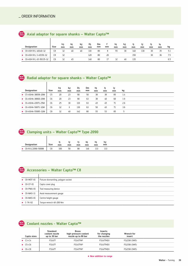
radial adaptor for square shanks – Walter capto™
Designation sizeh3
mmb2
mmD1
mmDmmm
h1mm
l1mm
l2mm kg
★ C5-ASHA-38058-20M C5 20 23 90 50 38 38 85 1.4
★ C6-ASHA-38060-20M C6 20 23 90 63 38 40 60 1.9
★ C6-ASHA-45071-25M C6 25 30 110 63 45 45 71 2.6
★ C6-ASHA-50071-32M C6 32 X 130 63 50 45 71 3.6
★ C8-ASHA-55085-32M C8 32 40 142 80 55 53 85 5
clamping units – Walter capto™ Type 2090
Designation sizel1
mml2
mml3
mmb1
mmh1
mmh2
mm
★ C8-R/lC2090-50088 C8 100 50 88 146 133 133
coolant nozzles - Walter capto™
capto sizes
standard coolant nozzle up to 30 bar
brass high-pressure coolant
nozzle up to 80 bar
inserts for changing the nozzles
Wrench for insert
★ C3+C4 FS1477 FS1477HP FS1477HEX FS2158 (SW5)
★ C5+C6 FS1477 FS1477HP FS1477HEX FS2158 (SW5)
★ C6+C8 FS1477 FS1477HP FS1477HEX FS2158 (SW5)
accessories – Walter capto™ c8
★ C8-WDT-01 Fixture dismantling, polygon socket
★ C8-CP-01 Capto cover plug
★ C8-PMu-01 Tool measuring device
★ C8-MAS-11 Axial measurement gauge
★ C8-MAS-01 Centre height gauge
★ C-TK-02 Torque wrench 40-200 nm
NEW2010
NEW2010
NEW2010
NEW2010
axial adaptor for square shanks – Walter capto™
Designation sizeh3
mmb1
mmb2
mmD1
mmDmmm
fmm
h1mm
h2mm
l1mm
l2mm
l3mm
l4mm kg
★ C8-ASH R/l-40140-32 C8 32 40 40 110 80 8 55 30 140 130 30 35 5.1
★ C8-ASH R/l 3-45150-32 C8 32 120 80 20 150 30 36 7.5
★ C8-ASH R/l 45-50135-32 C8 32 45 140 80 17 32 40 135 6.5
NEW2010
★ new addition to range

Turning
Drilling & ThrEaDing
Milling
Walter 3ISO indexable inserts 4 and 12ISO turning toolholders 6 and 19Grooving 10 and 22Order information 24
Walter Titex 41Solid carbide drills 42PCD drill 46Order information 48
Walter 55Boring tools 56Reaming inserts 58Indexable & Point Drills 60Order information 66
Walter Prototyp 75Solid carbide thread milling cutters 76HSS thread former 79Solid carbide taps 82Order information 84
Walter Prototyp 97Solid carbide end mills 98Order information 104
Walter 125Cutting tool materials 126 and 140Face, shoulder, slot and copy mills 128 and 142Order information 152
Alphanumeric index 170

_TOOl InnOvATIOnS In DRIllInG
Extremely innovative, extremely productive.
Product innovations Edition 2010-1
Drilling & Threading

Special flute geometry and polished flutes for reliable chip evacuation combined with a high level of process reliability
42
your aDvanTagEs
Optimised flute geometry for reliable chip removal for –small diameters and large drilling depthsHigh level of process reliability without pecking –Much greater productivity in comparison to HSS drilling –and reaming tools, single lip drills, and solid carbide drills with pecking
SOlID CARBIDE DRIllS
Walter Titex x·treme DM20 and DM25,x·treme Pilot 150.
Matched coolant channels for optimum cooling at the cutting edge
AMP coating for high wear resistance and maximum tool life
X·treme Pilot 150: diameter tolerance matched to
X·treme DM20 and DM25
X·treme DM20, DM25 and Pilot 150 Types: A6789AMP / A6889AMP / A6181AMl
ThE Tool
Solid carbide micro high performance drill with –internal coolingAMP coating on X·treme DM20 and DM25 –‡ tip coatingAMl coating on X·treme Pilot 150 –Drilling depth 20 x d and 25 x d –Ø range 2–2.9 mm –Shank in accordance with DIn 6535 HA –
aPPlicaTions
For material groups P, K, M, n, S –Can be used with emulsion and oil –For use in general engineering, the automotive industry, –mould and die making and the energy industry
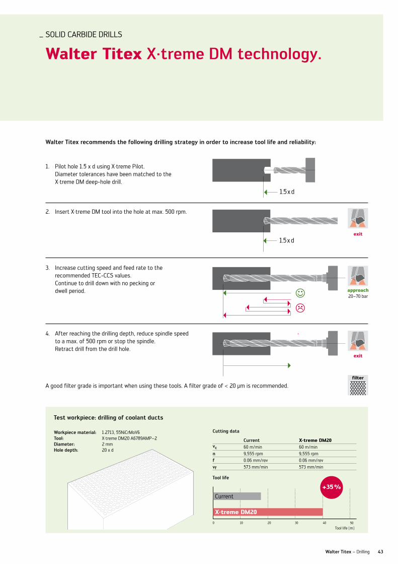
Test workpiece: drilling of coolant ducts
cutting data
current X·treme DM20vc 60 m/min 60 m/minn 9,555 rpm 9,555 rpmf 0.06 mm/rev 0.06 mm/revvf 573 mm/min 573 mm/min
Tool life
0 10 20 30 40
+35 %
Workpiece material: 1.2713, 55niCrMov6Tool: X·treme DM20 A6789AMP–2Diameter: 2 mmhole depth: 20 x d
50
Current
X·treme DM20
Tool life [m]
1,5xd
1,5xd
1,5xd
1,5xd
1,5xd
1,5xd
1,5xd
1,5xd
43Walter Titex – Drilling
SOlID CARBIDE DRIllS
Walter Titex x·treme DM technology.
Walter Titex recommends the following drilling strategy in order to increase tool life and reliability:
1. Pilot hole 1.5 x d using X·treme Pilot. Diameter tolerances have been matched to the X·treme DM deep-hole drill.
2. Insert X·treme DM tool into the hole at max. 500 rpm.
3. Increase cutting speed and feed rate to the recommended TEC-CCS values. Continue to drill down with no pecking or dwell period.
4. After reaching the drilling depth, reduce spindle speed to a max. of 500 rpm or stop the spindle. Retract drill from the drill hole.
exit
exit
approach20–70 bar
A good filter grade is important when using these tools. A filter grade of < 20 µm is recommended.filter
1.5 x d
1.5 x d
44
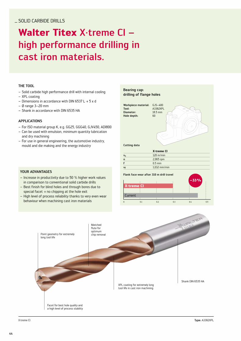
SOlID CARBIDE DRIllS
Walter Titex x·treme ci – high performance drilling in cast iron materials.
ThE Tool
Solid carbide high performance drill with internal cooling –XPl coating –Dimensions in accordance with DIn 6537 l ‡ 5 x d –Ø range 3–20 mm –Shank in accordance with DIn 6535 HA –
aPPlicaTions
For ISO material group K, e.g. GG25, GGG40, GJv450, ADI800 –Can be used with emulsion, minimum quantity lubrication –and dry machiningFor use in general engineering, the automotive industry, –mould and die making and the energy industry
your aDvanTagEs
Increase in productivity due to 50 % higher work values –in comparison to conventional solid carbide drillsBest finish for blind holes and through bores due to – special facet ‡ no chipping at the hole exitHigh level of process reliability thanks to very even wear –behaviour when machining cast iron materials
bearing cap: drilling of flange holes
cutting data
X·treme CIvc 120 m/minn 2,065 rpmf 0.5 mmvf 1,032 mm/min
flank face wear after 310 m drill travel
0 0.1 0.2 0.3 0.50.4
X·treme CI
Current
–33 %
Workpiece material: GJS–400Tool: A3382XPlDiameter: 18.5 mmhole depth: 60
X·treme CI Type: A3382XPl
Point geometry for extremely long tool life
Facet for best hole quality and a high level of process stability
XPl coating for extremely long tool life in cast iron machining
Shank DIn 6535 HA
Matched flute for optimum chip removal

45Walter Titex – Drilling
SOlID CARBIDE DRIllS
Walter Titex x·treme D8 and D12 – the new dimension in drilling depths 8 x d and 12 x d.
ThE Tool
Solid carbide high – performance drill with internal coolingDPP coating –‡ tip coatingDrilling depth 8 x d and –12 x dØ range 3–20 mm –Shank in accordance with –DIn 6535 HA4-chamfer design –
aPPlicaTions
For the ISO material –groups P, K (M, n, S)Can be used with emulsion –and minimum quantity lubricationFor use in general engi- –neering, the automotive industry, mould and die making and the energy industry
your aDvanTagEs
Drilling without pecking –down to a drilling depth of 12 x dOptimum alignment and –excellent surface fin-ish on the component thanks to matched ar-rangement of 4 lands50–100 % higher –productivity in com-parison to conven-tional solid carbide drills thanks to the use of high cutting parametersMaximum process reli- –ability thanks to reliable chip evacuation
X·treme D8 and D12 Types: A6489DPP / A6589DPP
Point geometry for extremely high cutting rate
4 lands for optimum hole finish
DPP coating for extremely long tool life
Polished flute for reliable chip evacuation
Exhaust manifold: drilling of mounting hole
cutting data
current X·treme D8vc 180 m/min 160 m/minn 6,366 rpm 5,658 rpmf 0.2 mm/rev 0.25 mm/revvf 1,273 mm/min 1,415 mm/min
Workpiece material: En–GJS–XSiMo 4.10 (GGG Si Mo)Tool: A6489DPP–9 Diameter: 9 mmhole depth: 80 mm
Drill travel with 10 % higher cutting parameters
0 10 20 30 40 50
+35 %
60
Current
X·treme D8
Drill travel [m]

46
PCD DRIllS
Walter Titex PcD rivet countersinks and twist drills for composite materials.
ThE Tools
Drilling and reaming tools and rivet countersinks with helical –PCD drill pointOptimised for composite materials –Geometry for reducing the cutting force, thereby avoiding –delamination (frayed hole exit)Multiple reconditioning –
aPPlicaTions
For a wide variety of CFRP materials –GFRP materials –For use on abrasive materials in the aerospace industry –and all composite material machining industries For bores or rivet holes with countersink where high quality –is requiredSuitable for fully or semi-automated production processes –(CnC and power feed)
your aDvanTagEs
High tool life, especially in comparison with PCD coated –toolsProcess stability even at high cutting parameters –High process stability due to the PCD sinter technology; –no tool failure caused by failed solder jointsEvery tool diameter between 2.0 mm and 6.4 mm –availableReduction of typical application problems such as – delamination and burrsRegrinding service to reduce tool costs –
PCD rivet countersinks PCD twist drills
Custom-designed point geometry for PCD drill points
Component-defined chamfer step
Tungsten carbide drill body

180
160
140
120
100
80
60
40
20
0
-205.17 36.220.7 51.7 56.810.3 41.325.815.5 46.531.0
47Walter Titex – Drilling
ThE MaTErial
various composite – materials for the aero-space industry Pre-impregnated fibres –in different directions (0°/90°, 45°)liners with linen fabric –
ThE holEs
Good quality at hole exit –after e.g. 600 holes drilledOnly very little delamina- –tion or fine fibres visible at hole exit Good quality surface in –the hole
Hole surface
Fz hole 1 - 15 Fz hole 586 - 600
Axial force comparison per row for the first and last holes (586 - 600 hole)
Hole exit 1st hole
Permitted diameter for delamination 8.35 mm with a tool diameter of 6.35 mm
Hole exit 600th hole
ThE forcEs
Minimised axial force –for reduced tendency to delaminate Moderate increase in –force up to end of tool life
Why PcD?
Significant improve- –ment in tool lifeImproved hole quality –Higher cutting para- –meters Sharper cutting edge –Reduced thermal –impactOptimum thermal – conductivity of the cutting tool materialMinimised risk of – delaminationDry machining possible –Repeated regrinding –possible

ORDER InFORMATIOn
48
x·treme ci a3382xPl
d1 mmm7
Øinches/
no.
d2 mmh6
l1 mm
l2 mmmax.
l4 mm
order code
A3382XPL...
3,000 6 66 28 36 -3
3,100 6 66 28 36 -3.1
3,175 1/8In 6 66 28 36 -1/8In
3,200 6 66 28 36 -3.2
3,300 6 66 28 36 -3.3
3,400 6 66 28 36 -3.4
3,500 6 66 28 36 -3.5
3,572 9/64In 6 66 28 36 -9/64In
3,600 6 66 28 36 -3.6
3,700 6 66 28 36 -3.7
3,800 6 74 36 36 -3.8
3,900 6 74 36 36 -3.9
3,969 5/32In 6 74 36 36 -5/32In
4,000 6 74 36 36 -4
4,100 6 74 36 36 -4.1
4,200 6 74 36 36 -4.2
4,300 6 74 36 36 -4.3
4,366 11/64In 6 74 36 36 -11/64In
4,400 6 74 36 36 -4.4
4,500 6 74 36 36 -4.5
4,600 6 74 36 36 -4.6
4,650 6 74 36 36 -4.65
4,700 6 74 36 36 -4.7
4,763 3/16In 6 82 44 36 -3/16In
4,800 6 82 44 36 -4.8
4,900 6 82 44 36 -4.9
5,000 6 82 44 36 -5
5,100 6 82 44 36 -5.1
5,159 13/64In 6 82 44 36 -13/64In
5,200 6 82 44 36 -5.2
5,300 6 82 44 36 -5.3
5,400 6 82 44 36 -5.4
5,500 6 82 44 36 -5.5
5,550 6 82 44 36 -5.55
5,556 7/32In 6 82 44 36 -7/32In
5,600 6 82 44 36 -5.6
5,700 6 82 44 36 -5.7
5,800 6 82 44 36 -5.8
5,900 6 82 44 36 -5.9
5,953 15/64In 6 82 44 36 -15/64In
6,000 6 82 44 36 -6
6,100 8 91 53 36 -6.1
6,200 8 91 53 36 -6.2
6,300 8 91 53 36 -6.3
6,350 1/4In 8 91 53 36 -1/4In
6,400 8 91 53 36 -6.4
6,500 8 91 53 36 -6.5
6,600 8 91 53 36 -6.6
6,700 8 91 53 36 -6.7
6,747 17/64In 8 91 53 36 -17/64In
6,800 8 91 53 36 -6.8
6,900 8 91 53 36 -6.9
7,000 8 91 53 36 -7
7,100 8 91 53 36 -7.1
7,144 9/32In 8 91 53 36 -9/32In
x·treme DM20 a6789aMP
d1 mmh7
d2 mmh6
l1 mm
l2 mmmax.
order code
A6789AMP...
2,000 3 89 47 -2
2,100 3 89 49 -2.1
2,200 3 89 52 -2.2
2,300 3 96 54 -2.3
2,400 3 96 56 -2.4
2,500 3 96 59 -2.5
2,600 3 106 61 -2.6
2,700 3 106 63 -2.7
2,800 3 106 66 -2.8
2,900 3 106 68 -2.9
x·treme Pilot 150 a6181aMl
d1 mmp7
d2 mmh6
l1 mm
l2 mmmax.
order code
A6181AML...
2,000 3 57 10 -2
2,100 3 57 11 -2.1
2,200 3 57 11 -2.2
2,300 3 59 12 -2.3
2,400 3 59 12 -2.4
2,500 3 59 13 -2.5
2,600 3 62 13 -2.6
2,700 3 62 14 -2.7
2,800 3 62 14 -2.8
2,900 3 62 15 -2.9
x·treme DM25 a6889aMP
d1 mmh7
d2 mmh6
l1 mm
l2 mmmax.
order code
A6889AMP...
2,500 3 106 71 -2.5
2,600 3 121 74 -2.6
2,700 3 121 77 -2.7
2,800 3 121 80 -2.8
2,900 3 121 83 -2.9

ORDER InFORMATIOn
49Walter Titex – Drilling
x·treme ci a3382xPl
d1 mmm7
Øinches/
no.
d2 mmh6
l1 mm
l2 mmmax.
l4 mm
order code
A3382XPL...
7,200 8 91 53 36 -7.2
7,300 8 91 53 36 -7.3
7,400 8 91 53 36 -7.4
7,500 8 91 53 36 -7.5
7,541 19/64In 8 91 53 36 -19/64In
7,800 8 91 53 36 -7.8
7,900 8 91 53 36 -7.9
7,938 5/16In 8 91 53 36 -5/16In
8,000 8 91 53 36 -8
8,100 10 103 61 40 -8.1
8,200 10 103 61 40 -8.2
8,300 10 103 61 40 -8.3
8,334 21/64In 10 103 61 40 -21/64In
8,400 10 103 61 40 -8.4
8,500 10 103 61 40 -8.5
8,600 10 103 61 40 -8.6
8,700 10 103 61 40 -8.7
8,731 11/32In 10 103 61 40 -11/32In
8,800 10 103 61 40 -8.8
9,000 10 103 61 40 -9
9,128 23/64In 10 103 61 40 -23/64In
9,200 10 103 61 40 -9.2
9,300 10 103 61 40 -9.3
9,500 10 103 61 40 -9.5
9,525 3/8In 10 103 61 40 -3/8In
9,600 10 103 61 40 -9.6
9,800 10 103 61 40 -9.8
9,922 25/64In 10 103 61 40 -25/64In
10,000 10 103 61 40 -10
10,100 12 118 71 45 -10.1
10,200 12 118 71 45 -10.2
10,300 12 118 71 45 -10.3
10,319 13/32In 12 118 71 45 -13/32In
10,400 12 118 71 45 -10.4
10,500 12 118 71 45 -10.5
10,716 27/64In 12 118 71 45 -27/64In
10,800 12 118 71 45 -10.8
11,000 12 118 71 45 -11
11,100 12 118 71 45 -11.1
11,113 7/16In 12 118 71 45 -7/16In
11,200 12 118 71 45 -11.2
11,500 12 118 71 45 -11.5
11,509 29/64In 12 118 71 45 -29/64In
11,700 12 118 71 45 -11.7
11,800 12 118 71 45 -11.8
11,906 15/32In 12 118 71 45 -15/32In
12,000 12 118 71 45 -12
12,100 14 124 77 45 -12.1
12,200 14 124 77 45 -12.2
12,300 14 124 77 45 -12.3
12,303 31/64In 14 124 77 45 -31/64In
12,500 14 124 77 45 -12.5
12,600 14 124 77 45 -12.6
12,700 14 124 77 45 -12.7
12,700 1/2In 14 124 77 45 -1/2In
x·treme ci a3382xPl
d1 mmm7
Øinches/
no.
d2 mmh6
l1 mm
l2 mmmax.
l4 mm
order code
A3382XPL...
13,000 14 124 77 45 -13
13,300 14 124 77 45 -13.3
13,494 17/32In 14 124 77 45 -17/32In
13,500 14 124 77 45 -13.5
14,000 14 124 77 45 -14
14,288 9/16In 16 133 83 48 -9/16In
14,500 16 133 83 48 -14.5
15,000 16 133 83 48 -15
15,300 16 133 83 48 -15.3
15,500 16 133 83 48 -15.5
15,875 5/8In 16 133 83 48 -5/8In
16,000 16 133 83 48 -16
16,500 18 143 93 48 -16.5
17,000 18 143 93 48 -17
17,500 18 143 93 48 -17.5
18,000 18 143 93 48 -18
18,500 20 153 101 50 -18.5
19,000 20 153 101 50 -19
19,050 3/4In 20 153 101 50 -3/4In
20,000 20 153 101 50 -20

ORDER InFORMATIOn
50
x·treme D8 a6489DPP
d1 mmm7
Øinches/
no.
d2 mmh6
l1 mm
l2 mmmax.
l4 mm
order code
A6489DPP...
3,000 6 74 34 36 -3
3,100 6 74 34 36 -3.1
3,175 1/8 In 6 74 34 36 -1/8In
3,200 6 74 34 36 -3.2
3,300 6 74 34 36 -3.3
3,400 6 74 34 36 -3.4
3,500 6 74 34 36 -3.5
3,572 9/64 In 6 74 34 36 -9/64In
3,600 6 74 34 36 -3.6
3,700 6 74 34 36 -3.7
3,800 6 85 45 36 -3.8
3,900 6 85 45 36 -3.9
3,969 5/32 In 6 85 45 36 -5/32In
4,000 6 85 45 36 -4
4,100 6 85 45 36 -4.1
4,200 6 85 45 36 -4.2
4,300 6 85 45 36 -4.3
4,366 11/64 In 6 85 45 36 -11/64In
4,400 6 85 45 36 -4.4
4,500 6 85 45 36 -4.5
4,600 6 85 45 36 -4.6
4,700 6 85 45 36 -4.7
4,763 3/16 In 6 97 57 36 -3/16In
4,800 6 97 57 36 -4.8
4,900 6 97 57 36 -4.9
5,000 6 97 57 36 -5
5,100 6 97 57 36 -5.1
5,159 13/64 In 6 97 57 36 -13/64In
5,200 6 97 57 36 -5.2
5,300 6 97 57 36 -5.3
5,400 6 97 57 36 -5.4
5,500 6 97 57 36 -5.5
5,556 7/32 In 6 97 57 36 -7/32In
5,600 6 97 57 36 -5.6
5,700 6 97 57 36 -5.7
5,800 6 97 57 36 -5.8
5,900 6 97 57 36 -5.9
5,953 15/64 In 6 97 57 36 -15/64In
6,000 6 97 57 36 -6
6,100 8 106 66 36 -6.1
6,200 8 106 66 36 -6.2
6,300 8 106 66 36 -6.3
6,350 1/4 In 8 106 66 36 -1/4In
6,400 8 106 66 36 -6.4
6,500 8 106 66 36 -6.5
6,600 8 106 66 36 -6.6
x·treme D8 a6489DPP
d1 mmm7
Øinches/
no.
d2 mmh6
l1 mm
l2 mmmax.
l4 mm
order code
A6489DPP...
6,700 8 106 66 36 -6.7
6,747 17/64 In 8 106 66 36 -17/64In
6,800 8 106 66 36 -6.8
6,900 8 106 66 36 -6.9
7,000 8 106 66 36 -7
7,100 8 116 76 36 -7.1
7,144 9/32 In 8 116 76 36 -9/32In
7,200 8 116 76 36 -7.2
7,300 8 116 76 36 -7.3
7,400 8 116 76 36 -7.4
7,500 8 116 76 36 -7.5
7,541 19/64 In 8 116 76 36 -19/64In
★ 7,600 8 116 76 36 -7.6
7,700 8 116 76 36 -7.7
7,800 8 116 76 36 -7.8
★ 7,900 8 116 76 36 -7.9
7,938 5/16 In 8 116 76 36 -5/16In
8,000 8 116 76 36 -8
8,100 10 139 95 40 -8.1
8,200 10 139 95 40 -8.2
8,300 10 139 95 40 -8.3
★ 8,334 21/64 In 10 139 95 40 -21/64In
8,400 10 139 95 40 -8.4
8,500 10 139 95 40 -8.5
8,600 10 139 95 40 -8.6
8,700 10 139 95 40 -8.7
8,731 11/32 In 10 139 95 40 -11/32In
8,800 10 139 95 40 -8.8
★ 8,900 10 139 95 40 -8.9
9,000 10 139 95 40 -9
9,100 10 139 95 40 -9.1
★ 9,200 10 139 95 40 -9.2
9,128 23/64 In 10 139 95 40 -23/64In
9,300 10 139 95 40 -9.3
9,400 10 139 95 40 -9.4
9,500 10 139 95 40 -9.5
9,525 3/8 In 10 139 95 40 -3/8In
★ 9,600 10 139 95 40 -9.6
9,700 10 139 95 40 -9.7
9,800 10 139 95 40 -9.8
★ 9,900 10 139 95 40 -9.9
9,922 25/64 In 10 139 95 40 -25/64In
10,000 10 139 95 40 -10
10,100 12 163 114 45 -10.1
10,200 12 163 114 45 -10.2
10,300 12 163 114 45 -10.3
★ new addition to range
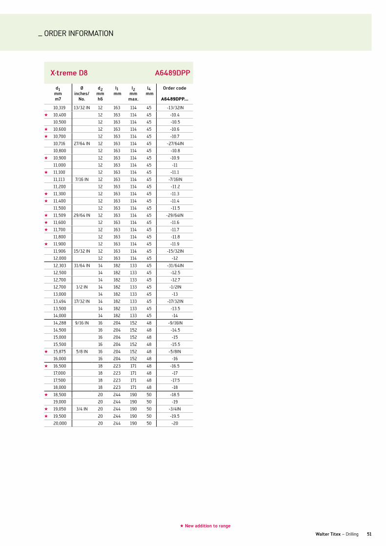
ORDER InFORMATIOn
51Walter Titex – Drilling
x·treme D8 a6489DPP
d1 mmm7
Øinches/
no.
d2 mmh6
l1 mm
l2 mmmax.
l4 mm
order code
A6489DPP...
10,319 13/32 In 12 163 114 45 -13/32In
★ 10,400 12 163 114 45 -10.4
10,500 12 163 114 45 -10.5
★ 10,600 12 163 114 45 -10.6
★ 10,700 12 163 114 45 -10.7
10,716 27/64 In 12 163 114 45 -27/64In
10,800 12 163 114 45 -10.8
★ 10,900 12 163 114 45 -10.9
11,000 12 163 114 45 -11
★ 11,100 12 163 114 45 -11.1
11,113 7/16 In 12 163 114 45 -7/16In
11,200 12 163 114 45 -11.2
★ 11,300 12 163 114 45 -11.3
★ 11,400 12 163 114 45 -11.4
11,500 12 163 114 45 -11.5
★ 11,509 29/64 In 12 163 114 45 -29/64In
★ 11,600 12 163 114 45 -11.6
★ 11,700 12 163 114 45 -11.7
11,800 12 163 114 45 -11.8
★ 11,900 12 163 114 45 -11.9
11,906 15/32 In 12 163 114 45 -15/32In
12,000 12 163 114 45 -12
12,303 31/64 In 14 182 133 45 -31/64In
12,500 14 182 133 45 -12.5
12,700 14 182 133 45 -12.7
12,700 1/2 In 14 182 133 45 -1/2In
13,000 14 182 133 45 -13
13,494 17/32 In 14 182 133 45 -17/32In
13,500 14 182 133 45 -13.5
14,000 14 182 133 45 -14
14,288 9/16 In 16 204 152 48 -9/16In
14,500 16 204 152 48 -14.5
15,000 16 204 152 48 -15
15,500 16 204 152 48 -15.5
★ 15,875 5/8 In 16 204 152 48 -5/8In
16,000 16 204 152 48 -16
★ 16,500 18 223 171 48 -16.5
17,000 18 223 171 48 -17
17,500 18 223 171 48 -17.5
18,000 18 223 171 48 -18
★ 18,500 20 244 190 50 -18.5
19,000 20 244 190 50 -19
★ 19,050 3/4 In 20 244 190 50 -3/4In
★ 19,500 20 244 190 50 -19.5
20,000 20 244 190 50 -20
★ new addition to range

ORDER InFORMATIOn
52
x·treme D12 a6589DPP
d1 mmm7
Øinches/
no.
d2 mmh6
l1 mm
l2 mmmax.
l4 mm
order code
A6589DPP...
3,000 6 92 54 36 -3
3,100 6 92 54 36 -3.1
3,175 1/8 In 6 92 54 36 -1/8In
3,200 6 92 54 36 -3.2
3,300 6 92 54 36 -3.3
3,400 6 92 54 36 -3.4
3,500 6 92 54 36 -3.5
3,572 9/64 In 6 92 54 36 -9/64In
3,600 6 92 54 36 -3.6
3,700 6 92 54 36 -3.7
3,800 6 102 64 36 -3.8
3,900 6 102 64 36 -3.9
3,969 -5/32In 6 102 64 36 -5/32In
4,000 6 102 64 36 -4
4,100 6 102 64 36 -4.1
4,200 6 102 64 36 -4.2
4,300 6 102 64 36 -4.3
4,366 -11/64In 6 102 64 36 -11/64In
4,400 6 102 64 36 -4.4
4,500 6 102 64 36 -4.5
4,600 6 102 64 36 -4.6
4,700 6 102 64 36 -4.7
4,763 -3/16In 6 121 83 36 -3/16In
4,800 6 121 83 36 -4.8
4,900 6 121 83 36 -4.9
5,000 6 121 83 36 -5
5,100 6 121 83 36 -5.1
5,159 -13/64In 6 121 83 36 -13/64In
5,200 6 121 83 36 -5.2
5,300 6 121 83 36 -5.3
5,400 6 121 83 36 -5.4
5,500 6 121 83 36 -5.5
★ 5,550 6 121 83 36 -5.55
5,556 -7/32In 6 121 83 36 -7/32In
5,600 6 121 83 36 -5.6
5,700 6 121 83 36 -5.7
5,800 6 121 83 36 -5.8
5,900 6 121 83 36 -5.9
6,000 6 121 83 36 -6
6,100 8 148 110 36 -6.1
6,200 8 148 110 36 -6.2
6,300 8 148 110 36 -6.3
x·treme D12 a6589DPP
d1 mmm7
Øinches/
no.
d2 mmh6
l1 mm
l2 mmmax.
l4 mm
order code
A6589DPP...
6,350 -1/4In 8 148 110 36 -1/4In
6,400 8 148 110 36 -6.4
6,500 8 148 110 36 -6.5
6,600 8 148 110 36 -6.6
6,700 8 148 110 36 -6.7
6,747 -17/64In 8 148 110 36 -17/64In
6,800 8 148 110 36 -6.8
6,900 8 148 110 36 -6.9
7,000 8 148 110 36 -7
7,100 8 148 110 36 -7.1
7,144 -9/32In 8 148 110 36 -9/32In
7,200 8 148 110 36 -7.2
★ 7,300 8 116 76 36 -7.3
7,400 8 148 110 36 -7.4
7,500 8 148 110 36 -7.5
7,541 -19/64In 8 148 110 36 -19/64In
7,800 8 148 110 36 -7.8
★ 7,900 8 116 76 36 -7.9
7,938 -5/16In 8 148 110 36 -5/16In
8,000 8 148 110 36 -8
8,100 10 180 138 40 -8.1
8,200 10 180 138 40 -8.2
8,300 10 180 138 40 -8.3
8,400 10 180 138 40 -8.4
8,500 10 180 138 40 -8.5
8,600 10 180 138 40 -8.6
8,700 10 180 138 40 -8.7
8,731 -11/32In 10 180 138 40 -11/32In
8,800 10 180 138 40 -8.8
9,000 10 180 138 40 -9
9,128 -23/64In 10 180 138 40 -23/64In
★ 9,200 10 139 95 40 -9.2
9,300 10 180 138 40 -9.3
9,500 10 180 138 40 -9.5
9,525 -3/8In 10 180 138 40 -3/8In
★ 9,600 10 139 95 40 -9.6
9,700 10 180 138 40 -9.7
9,800 10 180 138 40 -9.8
★ 9,922 25/64 In 10 180 138 40 -25/64In
10,000 10 180 138 40 -10
10,100 12 206 158 45 -10.1
10,200 12 206 158 45 -10.2
★ new addition to range

ORDER InFORMATIOn
53Walter Titex – Drilling
x·treme D12 a6589DPP
d1 mmm7
Øinches/
no.
d2 mmh6
l1 mm
l2 mmmax.
l4 mm
order code
A6589DPP...
10,300 12 206 158 45 -10.3
10,319 -13/32In 12 206 158 45 -13/32In
★ 10,400 12 163 114 45 -10.4
10,500 12 206 158 45 -10.5
10,716 -27/64In 12 206 158 45 -27/64In
10,800 12 206 158 45 -10.8
11,000 12 206 158 45 -11
★ 11,100 12 163 114 45 -11.1
11,113 -7/16In 12 206 158 45 -7/16In
11,200 12 206 158 45 -11.2
11,500 12 206 158 45 -11.5
★ 11,509 29/64 In 12 163 114 45 -29/64In
★ 11,700 12 163 114 45 -11.7
11,800 12 206 158 45 -11.8
11,906 -15/32In 12 206 158 45 -15/32In
12,000 12 206 158 45 -12
★ 12,100 14 230 182 45 -12.1
★ 12,200 14 230 182 45 -12.2
★ 12,300 14 230 182 45 -12.3
12,303 -31/64In 14 230 182 45 -31/64In
12,500 14 230 182 45 -12.5
★ 12,600 14 230 182 X -12.6
12,700 14 230 182 45 -12.7
12,700 -1/2In 14 230 182 45 -1/2In
13,000 14 230 182 45 -13
★ 13,494 17/32 In 18 223 171 48 -17/32In
13,500 14 230 182 45 -13.5
14,000 14 230 182 45 -14
14,288 -9/16In 16 260 208 48 -9/16In
14,500 16 260 208 48 -14.5
15,000 16 260 208 48 -15
15,500 16 260 208 48 -15.5
15,875 5/8 In 16 204 152 48 -5/8In
16,000 16 260 208 48 -16
★ 16,500 18 223 171 48 -16.5
17,000 18 285 234 48 -17
17,500 18 285 234 48 -17.5
18,000 18 285 234 48 -18
★ 18,500 20 244 190 50 -18.5
19,000 20 310 258 50 -19
★ 19,500 20 244 190 50 -19.5
20,000 20 310 258 50 -20
★ new addition to range
Turning
Drilling & ThrEaDing
Milling
Walter 3ISO indexable inserts 4 and 12ISO turning toolholders 6 and 19Grooving 10 and 22Order information 24
Walter Titex 41Solid carbide drills 42PCD drill 46Order information 48
Walter 55Boring tools 56Reaming inserts 58Indexable & Point Drills 60Order information 66
Walter Prototyp 75Solid carbide thread milling cutters 76HSS thread former 79Solid carbide taps 82Order information 84
Walter Prototyp 97Solid carbide end mills 98Order information 104
Walter 125Cutting tool materials 126 and 140Face, shoulder, slot and copy mills 128 and 142Order information 152
Alphanumeric index 170

_TOOl InnOvATIOnS In DRIllInG
Extremely accurate, extremely efficient.
Product innovations Edition 2010-1
Drilling & Threading

BORInG
Walter boring: new E47 universal geometry – excellent chip breaking, flexible and very economical.
56
ThE insErT
Indexable inserts in basic shape CC –Circumference-sintered design –Straight cutting edge –variable-width groove designed for different – cutting depthsProtective chamfer designed for the ISO – machining groupsvarious – Tiger·tec® cutting materials (PvD and CvD)
aPPlicaTions
The new E47 is suitable for all boring operations, –with and without interrupted cutThe WSM20 and WSM30 cutting materials are –multigrade cutting materials with PvD Tiger·tec® coating, which can be used with ISO M, S and P machining groups WPP20 is a CvD – Tiger·tec® cutting material used mainly with steel but also with cast iron materials
E47- ThE univErsal onE
15° rake angle –Flexible universal geometry for almost all –cutting depthsFor materials of ISO machining groups –P, M, K and S
your aDvanTagEs
Higher process stability due to excellent chip breaking –across the full cutting depth rangeFor universal use: –
optimum use from small (0.2 mm) to deep •cutting depths for several ISO groups •
Increased productivity due to: –higher cutting data from • Tiger·tec®
higher tool life thanks to optimum geometry design•
new geometry with variable groove width for excellent chip breaking
Tiger·tec® cutting materials to increase
the cutting data
Straight cutting edge for accurate shaping
Fully circumference-sintered
NEW2010

57Walter – Drilling
chip breaking comparison
indexable insert: CCMT060204cutting speed: vc = 200 m/min feed rate: f = 0.2 mmhole Ø: 35 mm cutting depth: ap = 1 mm
E47 geometry
Competitor
insErTs can bE usED in ThE folloWing Tool sysTEMs:
WalTEr boringMEDiuM
Dc = 20 – 153 mm
Proven nCT modular system and new ScrewFit screw head system
Cartridges for CC..0602.., CC..09T3.. –and CC..1204.. - indexable insertsSteel tool body –Depending on tool lengths –
WalTEr boringMaxi
Dc = 150 – 640 mm
Modular design with bridgesCoupling: nCT 80 –Cartridges for CC..1204. - indexable inserts –Depending on tool lengths –

58
REAMInG
Walter P6500 reaming inserts – for maximum precision in fine machining.
58
ThE cuTTing insErTs
5 different insert sizes per chamfer –Several chamfer variants (E1/E5) –Double-edged (Size 00 only single-edged) –B88 geometry: ground chip breaker groove 6°, –sharp-ground cutting edgeClamping area with increased roughness for –high insert seating stability
nEW cuTTing MaTErial Wxk05
High-strength micrograin substrate (ISO - K05) –Wear-resistant PvD-TiAln coating –
aPPlicaTions
E1 is a universal chamfer for all steel and cast –iron materialsE5 is particularly suitable for web holes, with –unstable components, and also for higher material removal (only in special bodies)
your aDvanTagEs
Increased productivity due to substantially higher tool life –Ideal adaptation of the tool to the machining conditions –with 2 special chamfer variantsHigher process stability due to defined roughness in the –clamping area of the insert
Type: P6500
lasered roughening
Adjustment device for rail-mounted tools
NEW2010

30°3°
1.3
75°
15°
0.55
59Walter – Drilling 59Walter – Drilling
Machining example
cutting data
15H7 40H7vc 80 m/min 114 m/minf 0.12 mm/rev 0.12 mm/rev
Workpiece material: GG25component: Cylinder head, basic hole cutting tool material: WXK05Tool: Stepped reamer 15H7/40H7cutting insert: P6500-4R-B88-E5lead angle: 75°
number of components comparison
0 200 400 600
Competitor 350
P6500 600
+70 %
sPEcial soluTions
Additional chamfer geometries and cutting tool materials are possible as special solutions for specific applications, such as Cermet cutting tool material for machining steel or PCD cutting tool material machining aluminium.
The chamfer geometries
cutting tool material
carbideWxk05
carbideWxk05
Materialsteel a b
cast iron a a
E1 E5

60
DRIllInG
Walter xtra·tec® insert Drill – very exact, very efficient, very economical.
ThE Tool
Solid drill featuring indexable inserts with four cutting edges –new: Ø range extended to 59 mm –Z = 1 effective –Drilling depth: 2 x D, 3 x D, 4 x D and – new 5 x DDiameter range: 16.5 - 59 mm –Ideal insert position ensures the forces are balanced out –during machiningOptimised chip clearance for better chip removal and tough –bodiesHard-nickel plated surface for protection against corrosion –and wear, and ensures a better flow of the chipsImproved handling and higher clamping and release torque –using TorxPlus screwsCylindrical collar for straightforward measurement of the –tool diameter
aPPlicaTions
For all steel and cast iron materials, as well as for stainless –materials and materials which are difficult to cut.For drilling, spot drilling on inclined or convex surfaces, –chain drillingIdeally suited for use in general mechanical engineering, –the automotive and mass production industries as well as in aerospace applications
your aDvanTagEs
Increase in productivity thanks to higher work values –low hole tolerance due to the optimum balance of forces –Cost reduction: –
4 real cutting edges•higher cutting parameters•saving on additional subsequent operations•
Excellent surface quality thanks to WIPER edge at the –hole diameterHigh level of process reliability thanks to positive locking –of the indexable insert
Additional indicator for position of the centre insert
Optimum arrangement of indexable inserts for balancing forces during machining
nickel-plated, helical flutes for optimum chip removal
Cylindrical collar for straightforward measurement of the tool diameter
xtra·tec® Insert Drill Types: B4212, B4213, B4214, B4215
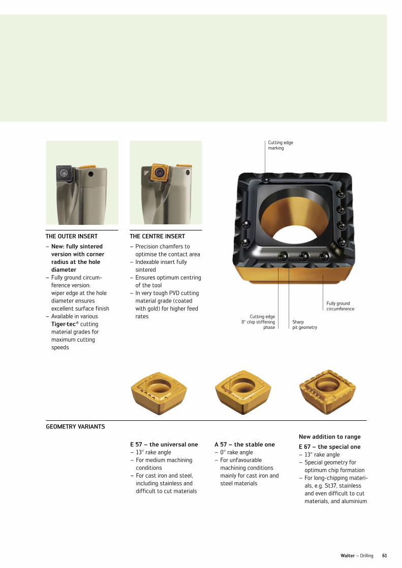
61Walter – Drilling
new: fully sintered – version with corner radius at the hole diameterFully ground circum- –ference version: wiper edge at the hole diameter ensures excellent surface finishAvailable in various –Tiger·tec® cutting material grades for maximum cutting speeds
E 57 – the universal one13° rake angle –For medium machining –conditionsFor cast iron and steel, –including stainless and difficult to cut materials
new addition to range
E 67 – the special one13° rake angle –Special geometry for – optimum chip formationFor long-chipping materi- –als, e.g. St37, stainless and even difficult to cut materials, and aluminium
Precision chamfers to –optimise the contact area Indexable insert fully –sinteredEnsures optimum centring –of the toolIn very tough PvD cutting –material grade (coated with gold) for higher feed rates
a 57 – the stable one0° rake angle – For unfavourable – machining conditions mainly for cast iron and steel materials
ThE ouTEr insErT ThE cEnTrE insErT
gEoMETry varianTs
Cutting edge marking
Cutting edge 0° chip stiffening
phaseSharp pit geometry
Fully ground circumference
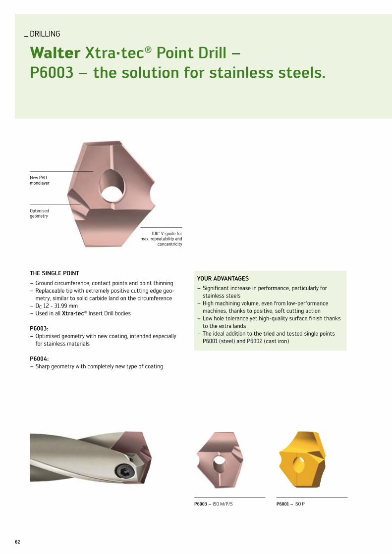
62
your aDvanTagEs
Significant increase in performance, particularly for –stainless steels High machining volume, even from low-performance –machines, thanks to positive, soft cutting actionlow hole tolerance yet high-quality surface finish thanks –to the extra landsThe ideal addition to the tried and tested single points –P6001 (steel) and P6002 (cast iron)
DRIllInG
Walter xtra·tec® Point Drill – P6003 – the solution for stainless steels.
new PvD monolayer
Optimised geometry
100° v-guide for max. repeatability and
concentricity
ThE singlE PoinT
Ground circumference, contact points and point thinning –Replaceable tip with extremely positive cutting edge geo- –metry, similar to solid carbide land on the circumference D – c 12 - 31.99 mm used in all – xtra·tec® Insert Drill bodies
P6003: Optimised geometry with new coating, intended especially –for stainless materials
P6004:Sharp geometry with completely new type of coating –
P6003 – ISO M/P/S P6001 – ISO P

63
your aDvanTagEs
Incredible increases in tool life compared to conventional –solutions Maximum process reliability thanks to optimum single –point in the tried and tested xtra·tec® Point Drill bodylow hole tolerance yet high-quality surface finish thanks –to the extra landsThe ideal addition to the tried and tested single points –P6001 (steel) and P6002 (cast iron)
Walter xtra·tec® Point Drill – P6004 black, sharp, aluminium.
Walter – Drilling
Sharp cutting edge
new type of layer
aPPlicaTions
P6003: For all stainless steels, difficult-to-cut materials and – long-chipping steelsFor use in general mechanical engineering, the energy –and aircraft industries
P6004:Especially for aluminium and aluminium alloys with or – without siliconFor use in general mechanical engineering, the automotive –and aircraft industries
P6002 – ISO K P6004 – ISO n
100° v-guide for max. repeat-
ability and concentricity
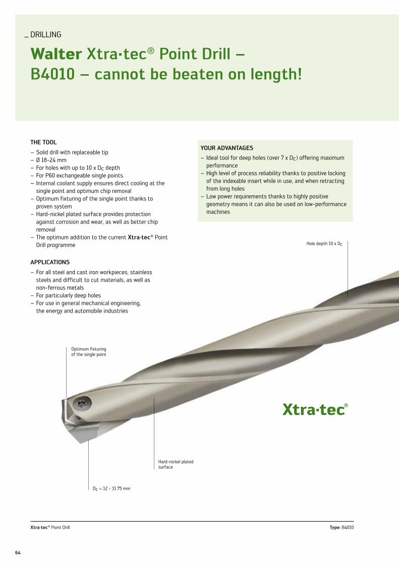
64
your aDvanTagEs
Ideal tool for deep holes (over 7 x D – c) offering maximum performanceHigh level of process reliability thanks to positive locking –of the indexable insert while in use, and when retracting from long holeslow power requirements thanks to highly positive – geometry means it can also be used on low-performance machines
DRIllInG
Walter xtra·tec® Point Drill – b4010 – cannot be beaten on length!
ThE Tool
Solid drill with replaceable tip –Ø 18-24 mm –For holes with up to 10 x D – c depthFor P60 exchangeable single points. –Internal coolant supply ensures direct cooling at the –single point and optimum chip removalOptimum fixturing of the single point thanks to –proven systemHard-nickel plated surface provides protection –against corrosion and wear, as well as better chip removalThe optimum addition to the current – xtra·tec® Point Drill programme
aPPlicaTions
For all steel and cast iron workpieces, stainless –steels and difficult to cut materials, as well as non-ferrous metalsFor particularly deep holes –For use in general mechanical engineering, –the energy and automobile industries
Optimum fixturing of the single point
Dc = 12 - 31.75 mm
xtra·tec® Point Drill Type: B4010
Hard-nickel plated surface
Hole depth 10 x Dc

65Walter – Drilling
xtra·tec® Point Drill Types: B4011. B4012C, B4013, B4015, B4017, B4010
10 x Dc1.3 x Dc 2.5 x Dc 3 x Dc 5 x Dc 7 x Dc

ORDER InFORMATIOn
66
xtra·tec® insert Drill b4212
DesignationDc mm
d1 mm
d2 mm
x1 mm
x2 mm
lc mm kg
no. of indexable
inserts Type
B4212.F32.36.Z1.072R–6 36 32 40 104 60 072 0.9 2
P484 . P–6RP484 . C–6R
B4212.F40.37.Z1.074R–6 37 40 50 114 70 074 1.3 2
B4212.F40.38.Z1.076R–6 38 40 50 116 70 076 1.4 2
B4212.F40.39.Z1.078R–6 39 40 50 118 70 078 1.4 2
B4212.F40.40.Z1.080R–6 40 40 50 120 70 080 1.4 2
B4212.F40.41.Z1.082R–6 41 40 50 122 70 082 1.4 2
B4212.F40.42.Z1.084R–6 42 40 50 124 70 084 1.5 2
B4212.F40.43.Z1.086R–7 43 40 50 126 70 086 1.5 2
P484 . P–7RP484 . C–7R
B4212.F40.44.Z1.088R–7 44 40 50 128 70 088 1.5 2
B4212.F40.45.Z1.090R–7 45 40 50 130 70 090 1.5 2
B4212.F40.46.Z1.092R–7 46 40 50 132 70 092 1.6 2
B4212.F40.47.Z1.094R–7 47 40 50 134 70 094 1.7 2
B4212.F40.48.Z1.096R–7 48 40 50 136 70 096 1.7 2
B4212.F40.49.Z1.098R–7 49 40 50 138 70 098 1.8 2
B4212.F40.50.Z1.100R–7 50 40 50 140 70 100 1.8 2
B4212.F40.51.Z1.102R–8 51 40 50 142 70 102 1.9 2
P484 . P–8RP484 . C–8R
B4212.F40.52.Z1.104R–8 52 40 50 144 70 104 1.9 2
B4212.F40.53.Z1.106R–8 53 40 50 146 70 106 1.9 2
B4212.F40.54.Z1.108R–8 54 40 50 148 70 108 2.0 2
B4212.F40.55.Z1.110R–8 55 40 50 150 70 110 2.0 2
B4212.F40.56.Z1.112R–8 56 40 50 152 70 112 2.1 2
B4212.F40.57.Z1.114R–8 57 40 50 154 70 114 2.2 2
B4212.F40.58.Z1.116R–8 58 40 50 156 70 116 2.3 2
B4212.F40.59.Z1.118R–8 59 40 50 158 70 118 2.4 2
xtra·tec® insert Drill b4213
DesignationDc mm
d1 mm
d2 mm
x1 mm
x2 mm
lc mm kg
no. of indexable
inserts Type
B4213.F32.36.Z1.108R–6 36 32 40 140 60 108 1 2
P484 . P–6RP484 . C–6R
B4213.F40.37.Z1.111R–6 37 40 50 151 70 111 1.6 2
B4213.F40.38.Z1.114R–6 38 40 50 154 70 114 1.6 2
B4213.F40.39.Z1.117R–6 39 40 50 157 70 117 1.6 2
B4213.F40.40.Z1.120R–6 40 40 50 160 70 120 1.7 2
B4213.F40.41.Z1.123R–6 41 40 50 163 70 123 1.7 2
B4213.F40.42.Z1.126R–6 42 40 50 166 70 126 1.7 2
B4213.F40.43.Z1.129R–7 43 40 50 169 70 129 1.7 2
P484 . P–7RP484 . C–7R
B4213.F40.44.Z1.132R–7 44 40 50 172 70 132 1.8 2
B4213.F40.45.Z1.135R–7 45 40 50 175 70 135 1.8 2
B4213.F40.46.Z1.138R–7 46 40 50 178 70 138 1.9 2
B4213.F40.47.Z1.141R–7 47 40 50 181 70 141 2.0 2
B4213.F40.48.Z1.144R–7 48 40 50 184 70 144 2.1 2
B4213.F40.49.Z1.147R–7 49 40 50 187 70 147 2.1 2
B4213.F40.50.Z1.150R–7 50 40 50 190 70 150 2.2 2
B4213.F40.51.Z1.153R–8 51 40 50 193 70 153 2.2 2
P484 . P–8RP484 . C–8R
B4213.F40.52.Z1.156R–8 52 40 50 196 70 156 2.2 2
B4213.F40.53.Z1.159R–8 53 40 50 199 70 159 2.3 2
B4213.F40.54.Z1.162R–8 54 40 50 202 70 162 2.4 2
B4213.F40.55.Z1.165R–8 55 40 50 205 70 165 2.5 2
B4213.F40.56.Z1.168R–8 56 40 50 208 70 168 2.6 2
B4213.F40.57.Z1.171R–8 57 40 50 211 70 171 2.7 2
B4213.F40.58.Z1.174R–8 58 40 50 214 70 174 2.8 2
B4213.F40.59.Z1.177R–8 59 40 50 217 70 177 2.9 2
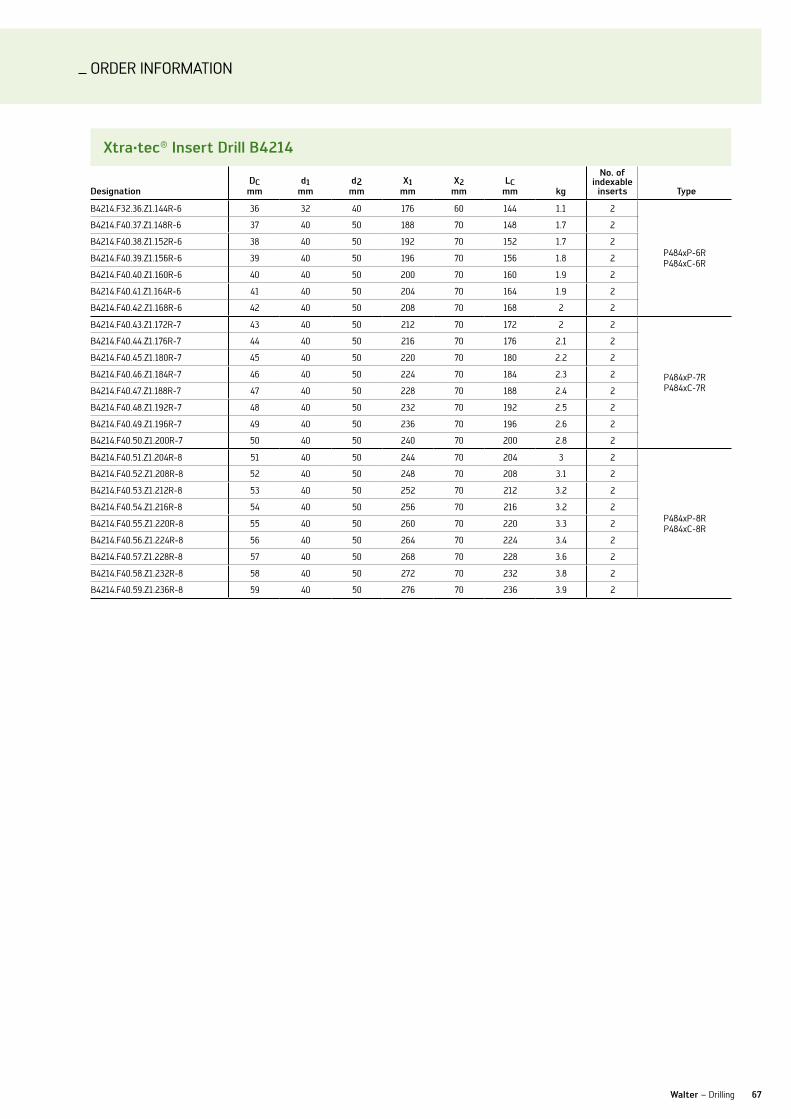
ORDER InFORMATIOn
67Walter – Drilling
xtra·tec® insert Drill b4214
DesignationDc mm
d1 mm
d2 mm
x1 mm
x2 mm
lc mm kg
no. of indexable
inserts Type
B4214.F32.36.Z1.144R-6 36 32 40 176 60 144 1.1 2
P484xP-6RP484xC-6R
B4214.F40.37.Z1.148R-6 37 40 50 188 70 148 1.7 2
B4214.F40.38.Z1.152R-6 38 40 50 192 70 152 1.7 2
B4214.F40.39.Z1.156R-6 39 40 50 196 70 156 1.8 2
B4214.F40.40.Z1.160R-6 40 40 50 200 70 160 1.9 2
B4214.F40.41.Z1.164R-6 41 40 50 204 70 164 1.9 2
B4214.F40.42.Z1.168R-6 42 40 50 208 70 168 2 2
B4214.F40.43.Z1.172R-7 43 40 50 212 70 172 2 2
P484xP-7RP484xC-7R
B4214.F40.44.Z1.176R-7 44 40 50 216 70 176 2.1 2
B4214.F40.45.Z1.180R-7 45 40 50 220 70 180 2.2 2
B4214.F40.46.Z1.184R-7 46 40 50 224 70 184 2.3 2
B4214.F40.47.Z1.188R-7 47 40 50 228 70 188 2.4 2
B4214.F40.48.Z1.192R-7 48 40 50 232 70 192 2.5 2
B4214.F40.49.Z1.196R-7 49 40 50 236 70 196 2.6 2
B4214.F40.50.Z1.200R-7 50 40 50 240 70 200 2.8 2
B4214.F40.51.Z1.204R-8 51 40 50 244 70 204 3 2
P484xP-8RP484xC-8R
B4214.F40.52.Z1.208R-8 52 40 50 248 70 208 3.1 2
B4214.F40.53.Z1.212R-8 53 40 50 252 70 212 3.2 2
B4214.F40.54.Z1.216R-8 54 40 50 256 70 216 3.2 2
B4214.F40.55.Z1.220R-8 55 40 50 260 70 220 3.3 2
B4214.F40.56.Z1.224R-8 56 40 50 264 70 224 3.4 2
B4214.F40.57.Z1.228R-8 57 40 50 268 70 228 3.6 2
B4214.F40.58.Z1.232R-8 58 40 50 272 70 232 3.8 2
B4214.F40.59.Z1.236R-8 59 40 50 276 70 236 3.9 2
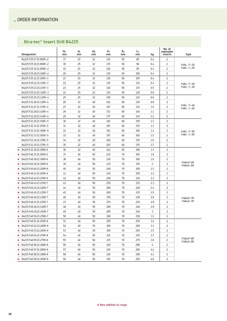
ORDER InFORMATIOn
68
xtra·tec® insert Drill b4215
DesignationDc mm
d1 mm
d2 mm
x1 mm
x2 mm
lc mm kg
no. of indexable
inserts Type
B4215.F25.17.Z1.085R–2 17 25 32 110 56 85 0.4 2
P484 . P–2R P484 . C–2R
B4215.F25.18.Z1.090R–2 18 25 32 115 56 90 0.4 2
B4215.F25.19.Z1.095R–2 19 25 32 120 56 95 0.4 2
B4215.F25.20.Z1.100R–2 20 25 32 125 56 100 0.4 2
B4215.F25.21.Z1.105R–3 21 25 32 130 56 105 0.4 2
P484 . P–3R P484 . C–3R
B4215.F25.22.Z1.110R–3 22 25 32 135 56 110 0.4 2
B4215.F25.23.Z1.115R–3 23 25 32 140 56 115 0.5 2
B4215.F25.24.Z1.120R–3 24 25 32 145 56 120 0.6 2
B4215.F25.25.Z1.125R–4 25 25 32 150 56 125 0.6 2
P484 . P–4R P484 . C–4R
B4215.F32.26.Z1.130R–4 26 32 40 162 60 130 0.8 2
B4215.F32.27.Z1.135R–4 27 32 40 167 60 135 1.0 2
B4215.F32.28.Z1.140R–4 28 32 40 172 60 140 1.1 2
B4215.F32.29.Z1.145R–4 29 32 40 177 60 145 1.2 2
B4215.F32.30.Z1.150R–5 30 32 40 182 60 150 1.3 2
P484 . P–5R P484 . C–5R
B4215.F32.31.Z1.155R–5 31 32 40 187 60 155 1.3 2
B4215.F32.32.Z1.160R–5 32 32 40 192 60 160 1.4 2
B4215.F32.33.Z1.165R–5 33 32 40 197 60 165 1.5 2
B4215.F32.34.Z1.170R–5 34 32 40 202 60 170 1.6 2
B4215.F32.35.Z1.175R–5 35 32 40 207 60 175 1.7 2
★ B4215.F32.36.Z1.180R-6 36 32 40 212 60 180 1.3 2
P484xP-6RP484xC-6R
★ B4215.F40.37.Z1.185R-6 37 40 50 225 70 185 1.8 2
★ B4215.F40.38.Z1.190R-6 38 40 50 230 70 190 1.9 2
★ B4215.F40.39.Z1.195R-6 39 40 50 235 70 195 2 2
★ B4215.F40.40.Z1.200R-6 40 40 50 240 70 200 2.1 2
★ B4215.F40.41.Z1.205R-6 41 40 50 245 70 205 2.2 2
★ B4215.F40.42.Z1.210R-6 42 40 50 250 70 210 2.3 2
★ B4215.F40.43.Z1.215R-7 43 40 50 255 70 215 2.3 2
P484xP-7RP484xC-7R
★ B4215.F40.44.Z1.220R-7 44 40 50 260 70 220 2.4 2
★ B4215.F40.45.Z1.225R-7 45 40 50 265 70 225 2.5 2
★ B4215.F40.46.Z1.230R-7 46 40 50 270 70 230 2.6 2
★ B4215.F40.47.Z1.235R-7 47 40 50 275 70 235 2.8 2
★ B4215.F40.48.Z1.240R-7 48 40 50 280 70 240 2.9 2
★ B4215.F40.49.Z1.245R-7 49 40 50 285 70 245 3 2
★ B4215.F40.50.Z1.250R-7 50 40 50 290 70 250 3.1 2
★ B4215.F40.51.Z1.255R-8 51 40 50 295 70 255 3.2 2
P484xP-8RP484xC-8R
★ B4215.F40.52.Z1.260R-8 52 40 50 300 70 260 3.3 2
★ B4215.F40.53.Z1.265R-8 53 40 50 305 70 265 3.5 2
★ B4215.F40.54.Z1.270R-8 54 40 50 310 70 270 3.7 2
★ B4215.F40.55.Z1.275R-8 55 40 50 315 70 275 3.8 2
★ B4215.F40.56.Z1.280R-8 56 40 50 320 70 280 4 2
★ B4215.F40.57.Z1.285R-8 57 40 50 325 70 285 4.2 2
★ B4215.F40.58.Z1.290R-8 58 40 50 330 70 290 4.4 2
★ B4215.F40.59.Z1.295R-8 59 40 50 335 70 295 4.6 2
★ new addition to range
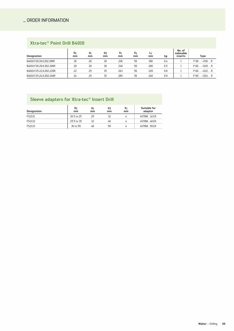
ORDER InFORMATIOn
69Walter – Drilling
xtra·tec® Point Drill b4010
DesignationDc mm
d1 mm
d2 mm
x1 mm
x2 mm
lc mm kg
no. of indexable
inserts Type
B4010.F20.18,0.Z02.180R 18 20 30 218 50 180 0.4 1 P 60 . . –D18 . . R
B4010.F20.20,0.Z02.200R 20 20 30 240 50 200 0.5 1 P 60 . . –D20 . . R
B4010.F25.22,0.Z02.220R 22 25 35 263 56 220 0.8 1 P 60 . . –D22 . . R
B4010.F25.24,0.Z02.240R 24 25 35 285 56 240 0.9 1 P 60 . . –D24 . . R
sleeve adapters for xtra·tec® insert Drill
DesignationDc mm
d2 mm
d3 mm
x1 mm
suitable for adaptor
FS2131 16.5 to 25 25 32 4 A170M…32.EX
FS2132 25.5 to 35 32 40 4 A170M…40.EX
FS2133 36 to 59 40 50 4 A170M…50.EX
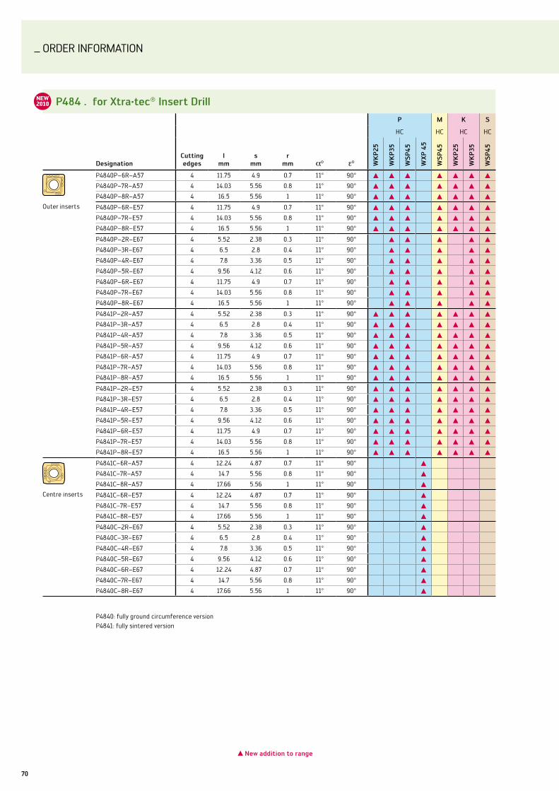
ORDER InFORMATIOn
70
P484 . for xtra·tec® insert Drill
Designationcutting edges
lmm
smm
rmm
P M k s
HC HC HC HC
Wk
P25
Wk
P35
Ws
P45
Wx
P 4
5
Ws
P45
Wk
P25
Wk
P35
Ws
P45
Outer inserts
P4840P–6R–A57 4 11.75 4.9 0.7 11° 90° L L L L L L L
P4840P–7R–A57 4 14.03 5.56 0.8 11° 90° L L L L L L L
P4840P–8R–A57 4 16.5 5.56 1 11° 90° L L L L L L L
P4840P–6R–E57 4 11.75 4.9 0.7 11° 90° L L L L L L L
P4840P–7R–E57 4 14.03 5.56 0.8 11° 90° L L L L L L L
P4840P–8R–E57 4 16.5 5.56 1 11° 90° L L L L L L L
P4840P–2R–E67 4 5.52 2.38 0.3 11° 90° L L L L L
P4840P–3R–E67 4 6.5 2.8 0.4 11° 90° L L L L L
P4840P–4R–E67 4 7.8 3.36 0.5 11° 90° L L L L L
P4840P–5R–E67 4 9.56 4.12 0.6 11° 90° L L L L L
P4840P–6R–E67 4 11.75 4.9 0.7 11° 90° L L L L L
P4840P–7R–E67 4 14.03 5.56 0.8 11° 90° L L L L L
P4840P–8R–E67 4 16.5 5.56 1 11° 90° L L L L L
P4841P–2R–A57 4 5.52 2.38 0.3 11° 90° L L L L L L L
P4841P–3R–A57 4 6.5 2.8 0.4 11° 90° L L L L L L L
P4841P–4R–A57 4 7.8 3.36 0.5 11° 90° L L L L L L L
P4841P–5R–A57 4 9.56 4.12 0.6 11° 90° L L L L L L L
P4841P–6R–A57 4 11.75 4.9 0.7 11° 90° L L L L L L L
P4841P–7R–A57 4 14.03 5.56 0.8 11° 90° L L L L L L L
P4841P–8R–A57 4 16.5 5.56 1 11° 90° L L L L L L L
P4841P–2R–E57 4 5.52 2.38 0.3 11° 90° L L L L L L L
P4841P–3R–E57 4 6.5 2.8 0.4 11° 90° L L L L L L L
P4841P–4R–E57 4 7.8 3.36 0.5 11° 90° L L L L L L L
P4841P–5R–E57 4 9.56 4.12 0.6 11° 90° L L L L L L L
P4841P–6R–E57 4 11.75 4.9 0.7 11° 90° L L L L L L L
P4841P–7R–E57 4 14.03 5.56 0.8 11° 90° L L L L L L L
P4841P–8R–E57 4 16.5 5.56 1 11° 90° L L L L L L L
Centre inserts
P4841C–6R–A57 4 12.24 4.87 0.7 11° 90° L
P4841C–7R–A57 4 14.7 5.56 0.8 11° 90° L
P4841C–8R–A57 4 17.66 5.56 1 11° 90° L
P4841C–6R–E57 4 12.24 4.87 0.7 11° 90° L
P4841C–7R–E57 4 14.7 5.56 0.8 11° 90° L
P4841C–8R–E57 4 17.66 5.56 1 11° 90° L
P4840C–2R–E67 4 5.52 2.38 0.3 11° 90° L
P4840C–3R–E67 4 6.5 2.8 0.4 11° 90° L
P4840C–4R–E67 4 7.8 3.36 0.5 11° 90° L
P4840C–5R–E67 4 9.56 4.12 0.6 11° 90° L
P4840C–6R–E67 4 12.24 4.87 0.7 11° 90° L
P4840C–7R–E67 4 14.7 5.56 0.8 11° 90° L
P4840C–8R–E67 4 17.66 5.56 1 11° 90° L
P4840: fully ground circumference versionP4841: fully sintered version
L new addition to range
NEW2010
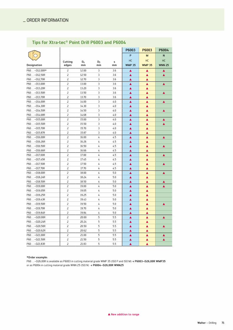
ORDER InFORMATIOn
71Walter – Drilling
Tips for xtra·tec® Point Drill P6003 and P6004
P6003 P6003 P6004P M n
Designationcutting edges
Dc mm
D1 mm
s mm
HC HC HC
WMP 35 WMP 35 Wnn 25
P60 . . –D12,00R* 2 12.00 3 3.6 L L L
P60 . . –D12,50R 2 12.50 3 3.6 L L L
P60 . . –D12,70R 2 12.70 3 3.6 L L
P60 . . –D13,00R 2 13.00 3 3.6 L L L
P60 . . –D13,20R 2 13.20 3 3.6 L L
P60 . . –D13,50R 2 13.50 3 3.6 L L L
P60 . . –D13,70R 2 13.70 3 3.6 L L
P60 . . –D14,00R 2 14.00 3 4.0 L L L
P60 . . –D14,30R 2 14.30 3 4.0 L L
P60 . . –D14,50R 2 14.50 3 4.0 L L L
P60 . . –D14,68R 2 14.68 3 4.0 L L
P60 . . –D15,00R 2 15.00 3 4.0 L L L
P60 . . –D15,50R 2 15.50 3 4.0 L L L
P60 . . –D15,70R 2 15.70 3 4.0 L L
P60 . . –D15,87R 2 15.87 3 4.0 L L
P60 . . –D16,00R 2 16.00 4 4.5 L L L
P60 . . –D16,26R 2 16.26 4 4.5 L L
P60 . . –D16,50R 2 16.50 4 4.5 L L L
P60 . . –D16,66R 2 16.66 4 4.5 L L
P60 . . –D17,00R 2 17.00 4 4.5 L L L
P60 . . –D17,45R 2 17.45 4 4.5 L L
P60 . . –D17,50R 2 17.50 4 4.5 L L L
P60 . . –D17,70R 2 17.70 4 4.5 L L
P60 . . –D18,00R 2 18.00 4 5.0 L L L
P60 . . –D18,24R 2 18.24 4 5.0 L L
P60 . . –D18,50R 2 18.50 4 5.0 L L L
P60 . . –D19,00R 2 19.00 4 5.0 L L L
P60 . . –D19,05R 2 19.05 4 5.0 L L
P60 . . –D19,25R 2 19.25 4 5.0 L L
P60 . . –D19,43R 2 19.43 4 5.0 L L
P60 . . –D19,50R 2 19.50 4 5.0 L L L
P60 . . –D19,70R 2 19.70 4 5.0 L L
P60 . . –D19,84R 2 19.84 4 5.0 L L
P60 . . –D20,00R 2 20.00 5 5.5 L L L
P60 . . –D20,24R 2 20.24 5 5.5 L L
P60 . . –D20,50R 2 20.50 5 5.5 L L L
P60 . . –D20,62R 2 20.62 5 5.5 L L
P60 . . –D21,00R 2 21.00 5 5.5 L L L
P60 . . –D21,50R 2 21.50 5 5.5 L L L
P60 . . –D21,83R 2 21.83 5 5.5 L L
*order example:P60 . . –D26,00R is available as P6003 in cutting material grade WMP 35 (ISO P and ISO M) ‡ P6003–D26,00r WMP35 or as P6004 in cutting material grade Wnn 25 (ISO n) ‡ P6004–D26,00r Wnn25
L new addition to range
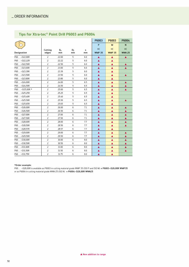
ORDER InFORMATIOn
72
Tips for xtra·tec® Point Drill P6003 and P6004
P6003 P6003 P6004P M n
Designationcutting edges
Dc mm
D1 mm
s mm
HC HC HC
WMP 35 WMP 35 Wnn 25
P60 . . –D22,00R 2 22.00 5 6.0 L L L
P60 . . –D22,22R 2 22.22 5 6.0 L L
P60 . . –D22,50R 2 22.50 5 6.0 L L L
P60 . . –D23,00R 2 23.00 5 6.0 L L L
P60 . . –D23,39R 2 23.39 5 6.0 L L
P60 . . –D23,50R 2 23.50 5 6.0 L L L
P60 . . –D23,80R 2 23.80 5 6.0 L L
P60 . . –D24,00R 2 24.00 5 6.5 L L L
P60 . . –D24,50R 2 24.50 5 6.5 L L L
P60 . . –D25,00R * 2 25.00 5 6.5 L L L
P60 . . –D25,25R 2 25.25 5 6.5 L L
P60 . . –D25,40R 2 25.40 5 6.5 L L
P60 . . –D25,50R 2 25.50 5 6.5 L L L
P60 . . –D25,65R 2 25.65 5 6.5 L L
P60 . . –D26,00R 2 26.00 6 7.1 L L L
P60 . . –D26,50R 2 26.50 6 7.1 L L L
P60 . . –D27,00R 2 27.00 6 7.1 L L L
P60 . . –D27,50R 2 27.50 6 7.1 L L L
P60 . . –D28,00R 2 28.00 6 7.7 L L L
P60 . . –D28,50R 2 28.50 6 7.7 L L L
P60 . . –D28,57R 2 28.57 6 7.7 L L
P60 . . –D29,00R 2 29.00 6 7.7 L L L
P60 . . –D29,50R 2 29.50 6 7.7 L L L
P60 . . –D30,00R 2 30.00 6 8.0 L L L
P60 . . –D30,50R 2 30.50 6 8.0 L L L
P60 . . –D31,00R 2 31.00 6 8.0 L L L
P60 . . –D31,50R 2 31.50 6 8.0 L L L
P60 . . –D31,75R 2 31.75 6 8.0 L L
*order example:P60 . . –D26,00R is available as P6003 in cutting material grade WMP 35 (ISO P and ISO M) ‡ P6003–D26,00r WMP35 or as P6004 in cutting material grade Wnn 25 (ISO n) ‡ P6004–D26,00r Wnn25
L new addition to range

ORDER InFORMATIOn
73Walter – Drilling
iso indexable insert boring tools ccMT – E47
Designationd
mml
mms
mmr
mm
P M k s
HC HC HC HC
WP
P20
Ws
M20
Ws
M30
Ws
M20
Ws
M30
WP
P20
Ws
M20
Ws
M30
CCMT 060202–E47 6.35 6.45 2.38 0.2 L L L L L L L L
CCMT 060204–E47 6.35 6.45 2.38 0.4 L L L L L L L L
CCMT 09T302–E47 9.525 9.67 3.97 0.2 L L L L L L L L
CCMT 09T304–E47 9.525 9.67 3.97 0.4 L L L L L L L L
CCMT 09T308–E47 9.525 9.67 3.97 0.8 L L L L L L L L
CCMT 120408–E47 12.7 12.9 4.76 0.8 L L L L L L L L
CCMT 120412–E47 12.7 12.9 4.76 1.2 L L L L L L L L
P6500 reaming insert
Designationcutting edges
l1 x i2mm
smm rake angle chamfer
P
HC
Wx
k05
P6500-OCR-B88-E5 1 11 x 1.5 1 6° E5 L
P6500-OP-B88-E5 2 20 x 2.5 1.2 6° E5 L
P6500-1P-B88-E5 2 20 x 3.0 1.5 6° E5 L
P6500-2P-B88-E5 2 20 x 4.5 2.0 6° E5 L
P6500-4P-B88-E5 2 25 x 7.0 2.3 6° E5 L
L new addition to range
NEW2010
NEW2010
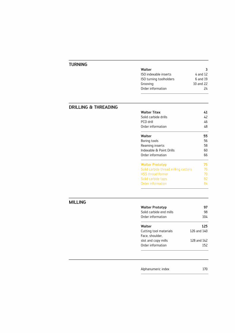
Turning
Drilling & ThrEaDing
Milling
Walter 3ISO indexable inserts 4 and 12ISO turning toolholders 6 and 19Grooving 10 and 22Order information 24
Walter Titex 41Solid carbide drills 42PCD drill 46Order information 48
Walter 55Boring tools 56Reaming inserts 58Indexable & Point Drills 60Order information 66
Walter Prototyp 75Solid carbide thread milling cutters 76HSS thread former 79Solid carbide taps 82Order information 84
Walter Prototyp 97Solid carbide end mills 98Order information 104
Walter 125Cutting tool materials 126 and 140Face, shoulder, slot and copy mills 128 and 142Order information 152
Alphanumeric index 170

_TOOl InnOvATIOnS In THREADInG
a new dimension in threading
Product innovations Edition 2010-1
Drilling & Threading

76
SOlID CARBIDE THREAD MIllS
Walter Prototyp drilling thread mill TMD for aluminium and cast iron workpieces.
NEW2010
DIMENSION RANgEM: M6 – M16
ThE Tool
Solid carbide high-performance drilling thread mills for – cutting internal threads in short-chipping aluminium and cast iron materialsSpecial micrograin carbide with high toughness and – increased wear resistanceMaximum tool life from special hard material coatings – specially adapted to suit a wide range of applications:
grey cast iron: TAX•cast aluminium: nHC•
Helix angle R27 in combination with a special groove form –guarantee optimum chip evacuationCentral coolant supply with three Y-shaped exits for – maximum tool stability Three milling edges and a special drilling geometry for – optimum machining ratesCutting length and 90° shaft countersink angle suitable –for 2 x d deep threads
aPPlicaTions
Blind and through hole threads up to 2 x d –Cast iron workpieces, e.g. GG25 –Cast aluminium from 1 % silicon content –Short-chipping magnesium and copper alloys –Direct machining of precast core holes –For use in the general mechanical engineering –and automotive industries
PrErEquisiTE
Stable application conditions –BAZ or turning milling centre with thread milling option –3D CnC control –HSC machines preferred –Internal cooling –For use in hydraulic expansion, shrink-fit and precision –chucksBand filter recommended for dimensions < M8 –
Three milling edges for 2 x d deep threads
Front face cutting area with special drilling geometry
Drilling thread mill Type: H5075018
90° countersink angle
Hard material coatings suitable for a wide range of applications
Central coolant supply with three Y-shaped exits
your aDvanTagEs
Maximum cost efficiency with drilling, countersinking –and thread milling in a single working cycle, thereby eliminating the need for unproductive tool changes and travel pathsIncreased productivity by shortening processing times –by up to 50 %Space savings in the tool magazine –Reduction of number and variety of tools as it is used –for both blind hole and through hole threadsPrecise positioning of the core hole against the milled –threadOutstanding thread quality (surface finish, thread – tolerance)Optimum cutting data and CnC program available from –our “TEC+CCS” expert system
Helix angle R27

77Walter Protoyp – Threading
Drilling, countersinking and thread milling – a single work cycle without tool change.
1. Positioning over core hole
3. Moving to the start position of the thread milling cycle
4. Radial plung-ing into the thread 180° / 1/4 lead
5. Generating threads in re-verse rotation using 360° helix, grinding on retraction at 180° to centre
6. Resetting the tool to the start position
Machining sEquEncE of Drilling ThrEaD Mill
compressor housing: thread milling of blind hole and through hole M6
cutting data
current Drilling thread mill TMDn 10,000 rpm 16,000 rpmz 2 3vf (drilling) 1,400 mm/min 1,800 mm/minvf (thread milling) 1,200 mm/min 1,440 mm/min
Workpiece material: AlSi12Cu (3.2583)Tensile strength: approx. 450 n/mm2
Tool: TMD-Z3coating: nHChole type: Blind &
through holeThread depth: 12 mm (2 x d)coolant: Emulsion
comparison of tool life (number of threads)
0 20,000 40,000 60,000
Current 40,000
Drilling thread mill TMD 60,000
+50 %
The result: Optimum productivity from shorter machining time in combination with 50 % higher tool life.
2. Spot drilling, drilling, sinking the core hole and chip removal
Wear-resistant, tough micrograin carbide

78
SOlID CARBIDE THREAD MIllS
Walter Prototyp solid carbide thread mills for hard machining of M2 upwards.
DIMENSION RANgEM: M2 - M6
ThE Tool
Right handed solid carbide orbital thread mill for hard – machiningSpecial carbide for extremely high wear resistance –Stable basic construction with strong web design –Heat-resistant TiAln coating, small helix angle and –negative cutting edge for a long tool lifelarger shank diameter for vibration-free use –Short milling edge for reduced cutting forces –Design for 2 x d deep threads –
aPPlicaTions
High-tensile materials R – m = approx. 1,400-1,600 n/mm² For use in hardened steels up to 65 HRC –Blind and through hole threads up to 2 x d thread depth –For applications in mould and die making, general – mechanical engineering, the aerospace industry and the medical industry
PrErEquisiTE
Stable application conditions –Machining centre with 3D-CnC control –MQl or air an advantage –
sPEcial ThrEaD Milling sTraTEgy
your aDvanTagEs
Maximum process reli- –ability when producing smaller threads e.g. M2 up to a thread depth of 2 x dHigh cost efficiency –thanks to shorter production times and longer tool lifeSignificantly reduced –risk of tool breakageReduced use of coolant –thanks to advantageous machining with MQl or air blastOutstanding thread –quality (surface finish, thread tolerance, cylindricity)Thread milling strat- –egy, optimum cutting data and CnC program available from our “TEC+CCS” expert system
Orbital thread milling cutter Type: H5083008
large core diameter
Helix angleR15
Short milling insert part
Wear-resistant, tough solid carbide
large shank diameter
TiAln coating
1. Positioning over core hole
2. Radial plunging into the thread 180°/half the lead
3. Generate threads in re-verse rotation using helix
4. Reset the tool to the centre and retract
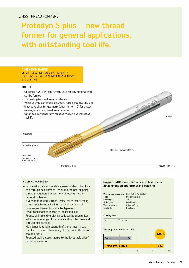
79Walter Protoyp – Threading
ThE Tool
universal HSS-E thread former, used for any material that –can be formedTin coating for ideal wear resistance –versions with lubrication grooves for deep threads (3.5 x d) –Innovative chamfer geometry (chamfer form C) for better –running-in and improved wear behaviourOptimised polygonal form reduces friction and increases –tool life
Tin coating
Optimised polygonal form
lubrication grooves
Innovative chamfer geometry (Chamfer form C)
HSS-E
DIMENSION RANgEM: M1 - M24 / Mf: M4 x 0.5 - M24 x 1.5 unc: unC2 - unC5/8 / unf: unF2 - unF5/8g: G 1/8 – G1
your aDvanTagEs
High level of process reliability, even for deep blind hole –and through hole threads, thanks to the non-chipping thread production process: no birdnesting, no chip removal problemsA very good thread surface, typical for thread forming –utmost machining reliability, particularly for small – dimensions, thanks to stable tool geometryFewer tool changes thanks to longer tool life –Reduction in tool diversity, since it can be used univer- –sally in a wide range of materials and for blind hole and through hole threadsHigh dynamic tensile strength of the formed thread –thanks to cold work hardening of the thread flanks and thread grooveReduced tooling costs thanks to the favourable price/ –performance ratio
lubrication grooves
Innovative chamfer geometry (chamfer form C)
support: M10 thread forming with high-speed attachment on operator stand machine
cutting data
vc 18 m/min
Tool edge life comparison (min)
0 50 100 150 200
Current 80
Protodyn S plus 183
+125 %
Workpiece material: St37 (1.0037 / S235JR)Tool: Protodyn S plus coating: Tinhole type: Blind holeThread depth: 20 mm (2 x d)coolant: Emulsion
Protodyn S plus Type: DP 20 61705
HSS THREAD FORMERS
Protodyn s plus – new thread former for general applications, with outstanding tool life.

80
HSS THREAD FORMERS
Protodyn s Eco plus – the next generation of high-performance thread formers.
ThE Tool
universal high-performance HSS-E thread former, used for –any material that can be formednew type of Tin hard material coating, perfected for thread –forming, with additional steam treatment for excellent tool life without cold weldingAlternative variant with graded TiCn multilayer coating, –intended in particular for carbon steels, and abrasive aluminium alloysversions with lubrication grooves and radial coolant exit –for deep threads (3.5 x d)Innovative chamfer geometry (chamfer forms C and E) for –better running-in and improved wear behaviourSpecial surface treatment combined with optimised poly- –gonal form reduces friction and enables use with minimum quantity lubrication (MQl)With or without axial coolant feed for chip removal from –core hole
PrErEquisiTE
Walter Prototyp thread formers are suitable for machining materials with a tensile strength of up to 1,200 n/mm² and at least 7 % elongation.
Reduced use of cooling lubricant thanks to the –possibility of MQl machiningvery cost efficient because it can be used for blind –hole and through hole threadsReduction in tool diversity, since it can be used – universally in a wide range of materials High dynamic tensile strength of the formed thread –thanks to cold work hardening of the thread flanks and thread groove
your aDvanTagEs
Maximum process reliability, even for deep blind hole and –through hole threads, thanks to the non-chipping thread production process: no bird-nesting, no chip removal problemsA very good thread surface, typical for thread forming –utmost machining reliability, particularly for small – dimensions, thanks to stable tool geometryFewer tool changes and optimum machine output – resulting from high forming speeds and significantly longer tool life
new type of Tin hard material coating
Optimised polygonal form
Redial internal cooling (axial as option)
lubrication grooves
DIMENSION RANgEM: M2 – M20 Mf: M8 x 1 – M16 x 1.5
Protodyn S ECO plus Type: EP 20 61745
Innovative chamfer geometry (chamfer forms C and E)
Special surface treatment

81Walter Protoyp – Threading
Protodyn s Eco plus
new, universal high-performance thread former, used for any material that can be formed.
Protodyn s Eco-inox
High-performance thread former particu-larly for machining stainless steels when using emulsion.
Protodyn Eco-lM
High-performance thread former with special geometry and extra-smooth surface for machining light metals which tend to cold weld.
Maximum machining reliability and profitability.
ProDucT ovErviEW: Eco ThrEaD forMEr
guide flange: M10 thread forming with vertical floating chuck
cutting data
current Protodyn S ECO plusvc 10 m/min 12 m/min
number of components comparison
0 50 100 150 200
Competitor 143
Protodyn S ECO plus 210
+46 %
Workpiece material: 42CrMo4 (1.7225)Tool: Protodyn S ECO pluscoating: Tinhole type: Blind holeThread depth: 15 mm (1.5 x d)coolant: EmulsionSteam-tempered
surface
HSS-E
aPPlicaTions
Blind and through hole threads up to 3.5 x d –Steel and stainless steel –long-chipping aluminium –Aluminium alloys (Si: < 12 %) –long-chipping copper and copper alloys –Ductile iron –

82 Walter Protoyp – Threading
SOlID CARBIDE TAPS
Walter Prototyp Paradur hsc high performance solid carbide tap for blind hole threads in steel materials.
ThE Tool
High performance solid carbide tap for blind hole threads in –steel materialsSpecial micrograin carbide with high wear resistance and –cutting edge strength, optimised for toughnessGraded TiCn multilayer hard material coating for fastest – cutting speeds and a long tool lifeSpecial chamfer geometry and reduced helix create perfect –chip breaking even in the case of long-chipping, soft materialsHelix angle R15 and axial internal cooling guarantee optimum –chip evacuation Shank tolerance h6 for use in hydraulic expansion, shrink-fit –and precision chucksHigh-precision concentricity (radial runout less than 10 µm) –for outstanding thread quality
aPPlicaTions
Blind hole thread down to max. 2 x d thread depth –Steel materials with a tensile strength greater than –850 n/mm² to moderate hardness (≤ 55 HRC), e.g. C70, 42CrMo4, X40CrMov5-1 (1.2344)Cast iron materials, e.g. GGG40, GJv450, ADI800 –Can be used with emulsion or minimum quantity lubrication –(MQl)Mass production in the automotive industry and in general –mechanical engineering with focus on minimum production costs per thread and considerable increases in productivity
PrErEquisiTE
Stable application conditions –Modern machining centres or transfer lines –Synchronised tapping (rigid tapping) or stable conventional –tool adaptors (floating chuck)Internal cooling –
your aDvanTagEs
Minimum production costs per thread on account –of threefold faster cutting speeds in comparison to HSS-E tapsFewer tool changes and optimum machine efficiency –resulting from significantly longer tool lifeReduced use of cooling lubricant thanks to the possibility –of MQl machiningHigh level of process reliability thanks to perfect chip –breaking (no birdnesting)Outstanding thread quality –
Graded TiCn multilayer hard material coating
Special chamfer geometry (chamfer form C)
Axial internal cooling
DIMENSION RANgEM: M6 - M12Mf: M6 x 0.75 - M16 x 1.5
Paradur HSC Type: 8041056
Helix angle R15

83
Perfect: short chips
Walter Protoyp – Threading
WalTEr ProToTyP ProToTEx hsc – through hole threads in steel materials with maximum productivity
offset connecting rod: tapping of M 9 x 1.25 blind and through holes with minimum compensation
blind hole cutting data
current Paradur HSCvc [m/min] 15 40regrinds 0 0number of threads 450 4,500
Through hole cutting data
current Prototex HSCvc [m/min] 40 45regrinds 2 0number of threads 6,400 13,500
Machining time comparison
The result:Maximum productivity thanks to 3x cutting speed and considerably longer tool life.
0 20 40 60 100 [h]14080 120 160
Workpiece material: C70 (1.1231)Tensile strength: approx. 1,050 n/mm²Tool: Paradur HSC & Prototex HSCcoating: TiCnhole type: Blind & through holesThread depth: 14 mm (1.5 x d)coolant: Emulsionnumber of components:
150,000
Special micrograin carbide
Optimised spiral point form B
Increased number of flutes
Graded multilayer TiCn hard material coating
lubrication grooves on the shank
Special carbide
Prototex HSC Type: 8021006
Further information on this tool can be found in our supplement catalogue and in TEC+CCS.
Competitor
Competitor
Prototex HSC
Paradur HSC
97hourstime
saving
Through hole
blind hole
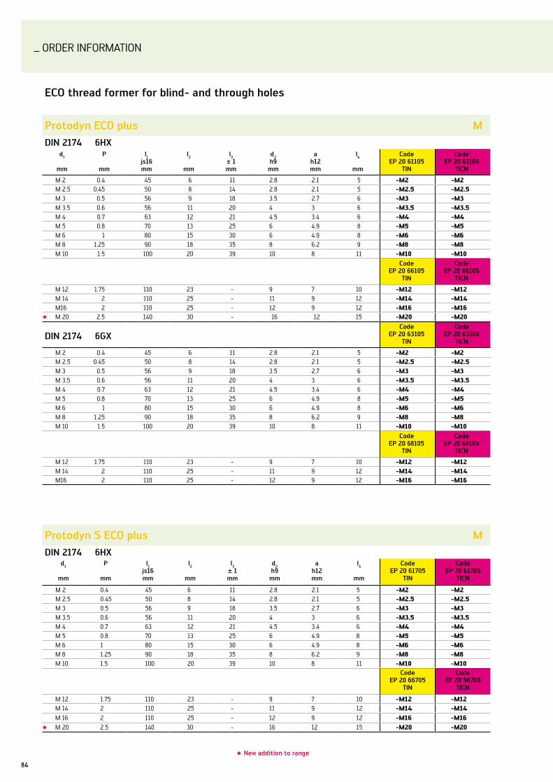
ORDER InFORMATIOn
84
Eco thread former for blind- and through holes
Protodyn Eco plus MDin 2174 6hx
d1
mm
P
mm
l1js16mm
l2
mm
l3± 1mm
d2h9
mm
ah12mm
l4
mm
codeEP 20 61105
Tin
codeEP 20 61106
Ticn
M 2 0.4 45 6 11 2.8 2.1 5 -M2 -M2 M 2.5 0.45 50 8 14 2.8 2.1 5 -M2.5 -M2.5 M 3 0.5 56 9 18 3.5 2.7 6 -M3 -M3 M 3.5 0.6 56 11 20 4 3 6 -M3.5 -M3.5 M 4 0.7 63 12 21 4.5 3.4 6 -M4 -M4 M 5 0.8 70 13 25 6 4.9 8 -M5 -M5 M 6 1 80 15 30 6 4.9 8 -M6 -M6 M 8 1.25 90 18 35 8 6.2 9 -M8 -M8 M 10 1.5 100 20 39 10 8 11 -M10 -M10
codeEP 20 66105
Tin
codeEP 20 66106
Ticn
M 12 1.75 110 23 - 9 7 10 -M12 -M12M 14 2 110 25 - 11 9 12 -M14 -M14M16 2 110 25 - 12 9 12 -M16 -M16
★ M 20 2.5 140 30 - 16 12 15 -M20 -M20
Din 2174 6gxcode
EP 20 63105Tin
codeEP 20 63106
Ticn
M 2 0.4 45 6 11 2.8 2.1 5 -M2 -M2 M 2.5 0.45 50 8 14 2.8 2.1 5 -M2.5 -M2.5 M 3 0.5 56 9 18 3.5 2.7 6 -M3 -M3 M 3.5 0.6 56 11 20 4 3 6 -M3.5 -M3.5 M 4 0.7 63 12 21 4.5 3.4 6 -M4 -M4 M 5 0.8 70 13 25 6 4.9 8 -M5 -M5 M 6 1 80 15 30 6 4.9 8 -M6 -M6 M 8 1.25 90 18 35 8 6.2 9 -M8 -M8 M 10 1.5 100 20 39 10 8 11 -M10 -M10
codeEP 20 68105
Tin
codeEP 20 68106
Ticn
M 12 1.75 110 23 - 9 7 10 -M12 -M12M 14 2 110 25 - 11 9 12 -M14 -M14M16 2 110 25 - 12 9 12 -M16 -M16
★ new addition to range
Protodyn s Eco plus MDin 2174 6hx
d1
mm
P
mm
l1js16mm
l2
mm
l3± 1mm
d2h9
mm
ah12mm
l4
mm
codeEP 20 61705
Tin
codeEP 20 61706
Ticn
M 2 0.4 45 6 11 2.8 2.1 5 -M2 -M2 M 2.5 0.45 50 8 14 2.8 2.1 5 -M2.5 -M2.5 M 3 0.5 56 9 18 3.5 2.7 6 -M3 -M3 M 3.5 0.6 56 11 20 4 3 6 -M3.5 -M3.5 M 4 0.7 63 12 21 4.5 3.4 6 -M4 -M4 M 5 0.8 70 13 25 6 4.9 8 -M5 -M5 M 6 1 80 15 30 6 4.9 8 -M6 -M6 M 8 1.25 90 18 35 8 6.2 9 -M8 -M8 M 10 1.5 100 20 39 10 8 11 -M10 -M10
codeEP 20 66705
Tin
codeEP 20 66706
Ticn
M 12 1.75 110 23 - 9 7 10 -M12 -M12M 14 2 110 25 - 11 9 12 -M14 -M14M 16 2 110 25 - 12 9 12 -M16 -M16
★ M 20 2.5 140 30 - 16 12 15 -M20 -M20

ORDER InFORMATIOn
85Walter Protoyp – Threading
Protodyn s Eco plus, with short chamfer form E MDin 2174 6hx
d1
mm
P
mm
l1js16mm
l2
mm
l3± 1mm
d2h9
mm
ah12mm
l4
mm
codeEP 20 61805
Tin
codeEP 20 61806
Ticn
M 2 0.4 45 6 11 2.8 2.1 5 -M2 -M2 M 2.5 0.45 50 8 14 2.8 2.1 5 -M2.5 -M2.5 M 3 0.5 56 9 18 3.5 2.7 6 -M3 -M3 M 3.5 0.6 56 11 20 4 3 6 -M3.5 -M3.5 M 4 0.7 63 12 21 4.5 3.4 6 -M4 -M4 M 5 0.8 70 13 25 6 4.9 8 -M5 -M5 M 6 1 80 15 30 6 4.9 8 -M6 -M6 M 8 1.25 90 18 35 8 6.2 9 -M8 -M8 M 10 1.5 100 20 39 10 8 11 -M10 -M10
codeEP 20 66805
Tin
codeEP 20 66806
Ticn
M 12 1.75 110 23 - 9 7 10 -M12 -M12M 14 2 110 25 - 11 9 12 -M14 -M14M 16 2 110 25 - 12 9 12 -M16 -M16
Din 2174 6gxcode
EP 20 63805Tin
codeEP 20 63806
Ticn
★ M 2 0.4 45 6 11 2.8 2.1 5 -M2 -M2 ★ M 2.5 0.45 50 8 14 2.8 2.1 5 -M2.5 -M2.5 ★ M 3 0.5 56 9 18 3.5 2.7 6 -M3 -M3 ★ M 3.5 0.6 56 11 20 4 3 6 -M3.5 -M3.5 ★ M 4 0.7 63 12 21 4.5 3.4 6 -M4 -M4 ★ M 5 0.8 70 13 25 6 4.9 8 -M5 -M5 ★ M 6 1 80 15 30 6 4.9 8 -M6 -M6 ★ M 8 1.25 90 18 35 8 6.2 9 -M8 -M8 ★ M 10 1.5 100 20 39 10 8 11 -M10 -M10
codeEP 20 68805
Tin
codeEP 20 68806
Ticn
★ M 12 1.75 110 23 - 9 7 10 -M12 -M12★ M 14 2 110 25 - 11 9 12 -M14 -M14★ M 16 2 110 25 - 12 9 12 -M16 -M16
Protodyn s Eco plus MDin 2174 6gx
d1
mm
P
mm
l1js16mm
l2
mm
l3± 1mm
d2h9
mm
ah12mm
l4
mm
codeEP 20 63706
Ticn
M 2 0.4 45 6 11 2.8 2.1 5 -M2 -M2 M 2.5 0.45 50 8 14 2.8 2.1 5 -M2.5 -M2.5 M 3 0.5 56 9 18 3.5 2.7 6 -M3 -M3 M 3.5 0.6 56 11 20 4 3 6 -M3.5 -M3.5 M 4 0.7 63 12 21 4.5 3.4 6 -M4 -M4 M 5 0.8 70 13 25 6 4.9 8 -M5 -M5 M 6 1 80 15 30 6 4.9 8 -M6 -M6 M 8 1.25 90 18 35 8 6.2 9 -M8 -M8 M 10 1.5 100 20 39 10 8 11 -M10 -M10
codeEP 20 68705
Tin
codeEP 20 68706
Ticn
M 12 1.75 110 23 - 9 7 10 -M12 -M12M 14 2 110 25 - 11 9 12 -M14 -M14M 16 2 110 25 - 12 9 12 -M16 -M16
★ new addition to range
NEW2010

ORDER InFORMATIOn
86
★ new addition to range
Protodyn s Eco plus, with internal coolant supply, radial exit 90° MDin 2174 6hx
d1
mm
P
mm
l1js16mm
l2
mm
l3± 1mm
d2h9
mm
ah12mm
l4
mm
codeEP 20 61745
Tin
codeEP 20 61746
Ticn
M 5 0.8 70 13 25 6 4.9 8 -M5 -M5 M 6 1 80 15 30 6 4.9 8 -M6 -M6 M 8 1.25 90 18 35 8 6.2 9 -M8 -M8 M 10 1.5 100 20 39 10 8 11 -M10 -M10
codeEP 20 66745
Tin
codeEP 20 66746
Ticn
M 12 1.75 110 23 - 9 7 10 -M12 -M12M 14 2 110 25 - 11 9 12 -M14 -M14M 16 2 110 25 - 12 9 12 -M16 -M16
★ M 20 2.5 140 30 - 16 12 15 -M20 -M20
Protodyn s Eco plus MfDin 2174 6hx
d1
mm
P
mm
l1js16mm
l2
mm
l3± 1mm
d2h9
mm
ah12mm
l4
mm
codeEP 21 66705
Tin
codeEP 21 66706
Ticn
M 8 1 90 18 - 6 4.9 8 -M8X1 -M8X1 M 10 1 90 20 - 7 5.5 8 -M10X1 -M10X1 M 12 1 100 21 - 9 7 10 -M12X1 -M12X1 M 12 1.5 100 21 - 9 7 10 -M12X1.5 -M12X1.5 M 14 1.5 100 21 - 11 9 12 -M14X1.5 -M14X1.5 M 16 1.5 100 21 - 12 9 12 -M16X1.5 -M16X1.5
Din 2174 6gxcode
EP 21 68705Tin
codeEP 21 68706
Ticn
M 8 1 90 18 - 6 4.9 8 -M8X1 -M8X1 M 10 1 90 20 - 7 5.5 8 -M10X1 -M10X1 M 12 1 100 21 - 9 7 10 -M12X1 -M12X1 M 12 1.5 100 21 - 9 7 10 -M12X1.5 -M12X1.5 M 14 1.5 100 21 - 11 9 12 -M14X1.5 -M14X1.5 M 16 1.5 100 21 - 12 9 12 -M16X1.5 -M16X1.5
Protodyn Eco plus, with internal coolant supply, axial exit MDin 2174 6hx
d1
mm
P
mm
l1js16mm
l2
mm
l3± 1mm
d2h9
mm
ah12mm
l4
mm
codeEP 20 61115
Tin
codeEP 20 61116
Ticn
★ M 5 0.8 70 13 25 6 4.9 8 -M5 -M5 ★ M 6 1 80 15 30 6 4.9 8 -M6 -M6 ★ M 8 1.25 90 18 35 8 6.2 9 -M8 -M8 ★ M 10 1.5 100 20 39 10 8 11 -M10 -M10
codeEP 20 66115
Tin
codeEP 20 66116
Ticn
★ M 12 1.75 110 23 - 9 7 10 -M12 -M12★ M 14 2 110 25 - 11 9 12 -M14 -M14★ M 16 2 110 25 - 12 9 12 -M16 -M16
NEW2010

ORDER InFORMATIOn
87Walter Protoyp – Threading
Protodyn Eco plus, with internal coolant supply, axial exit Mf Din 2174 6hx
d1
mm
P
mm
l1js16mm
l2
mm
l3± 1mm
d2h9
mm
ah12mm
l4
mm
codeEP 21 66115
Tin
codeEP 21 66116
Ticn
★ M 8 1 90 18 - 6 4.9 8 -M8X1 -M8X1 ★ M 10 1 90 20 - 7 5.5 8 -M10X1 -M10X1 ★ M 12 1 100 21 - 9 7 10 -M12X1 -M12X1 ★ M 12 1.5 100 21 - 9 7 10 -M12X1.5 -M12X1.5 ★ M 14 1.5 100 21 - 11 9 12 -M14X1.5 -M14X1.5 ★ M 16 1.5 100 21 - 12 9 12 -M16X1.5 -M16X1.5
NEW2010
Protodyn s Eco plus, with internal coolant supply, radial exit 90° MfDin 2174 6hx
d1
mm
P
mm
l1js16mm
l2
mm
l3± 1mm
d2h9
mm
ah12mm
l4
mm
codeEP 21 66745
Tin
codeEP 21 66746
Ticn
M 8 1 90 18 - 6 4.9 8 -M8X1 -M8X1 M 10 1 90 20 - 7 5.5 8 -M10X1 -M10X1 M 12 1 100 21 - 9 7 10 -M12X1 -M12X1 M 12 1.5 100 21 - 9 7 10 -M12X1.5 -M12X1.5 M 14 1.5 100 21 - 11 9 12 -M14X1.5 -M14X1.5 M 16 1.5 100 21 - 12 9 12 -M16X1.5 -M16X1.5
★ new addition to range

ORDER InFORMATIOn
88
Thread former hss-E for blind- and through holes
Protodyn plus MDin 2174 6hx ≤ M 1.4 : 5HX, ≥ M 1.6 : 6HX
d1
mm
P
mm
l1js16mm
l2
mm
l3± 1mm
d2h9
mm
ah12mm
l4
mm
codeDP 20 61105
Tin
M 1 0.25 40 5.5 - 2.5 2.1 5 -M1 M 1.1 0.25 40 5.5 - 2.5 2.1 5 -M1.1 M 1.2 0.25 40 5.5 - 2.5 2.1 5 -M1.2 M 1.4 0.3 40 7 - 2.5 2.1 5 -M1.4 M 1.6 0.35 40 8 - 2.5 2.1 5 -M1.6 M 1.7 0.35 40 8 - 2.5 2.1 5 -M1.7 M 1.8 0.35 40 8 - 2.5 2.1 5 -M1.8 M 2 0.4 45 6 11 2.8 2.1 5 -M2 M 2.2 0.45 45 7 12 2.8 2.1 5 -M2.2 M 2.3 0.4 45 7 12 2.8 2.1 5 -M2.3 M 2.5 0.45 50 8 14 2.8 2.1 5 -M2.5 M 2.6 0.45 50 8 14 2.8 2.1 5 -M2.6 M 3 0.5 56 9 18 3.5 2.7 6 -M3 M 3.5 0.6 56 11 20 4 3 6 -M3.5 M 4 0.7 63 12 21 4.5 3.4 6 -M4 M 5 0.8 70 13 25 6 4.9 8 -M5 M 6 1 80 15 30 6 4.9 8 -M6 M 7 1 80 15 30 7 5.5 8 -M7 M 8 1.25 90 18 35 8 6.2 9 -M8 M 10 1.5 100 20 39 10 8 11 -M10
codeDP 20 66105
Tin
M 12 1.75 110 23 - 9 7 10 -M12 M 14 2 110 25 - 11 9 12 -M14M 16 2 110 25 - 12 9 12 -M16M 18 2.5 125 30 - 14 11 14 -M18M 20 2.5 140 30 - 16 12 15 -M20M24 3 160 35 - 18 14.5 17 -M24
Din 2174 6gx code
DP 20 63105Tin
M 2 0.4 45 6 11 2.8 2.1 5 -M2 M 2.5 0.45 50 8 14 2.8 2.1 5 -M2.5 M 3 0.5 56 9 18 3.5 2.7 6 -M3 M 3.5 0.6 56 11 20 4 3 6 -M3.5 M 4 0.7 63 12 21 4.5 3.4 6 -M4 M 5 0.8 70 13 25 6 4.9 8 -M5 M 6 1 80 15 30 6 4.9 8 -M6 M 8 1.25 90 18 35 8 6.2 9 -M8 M 10 1.5 100 20 39 10 8 11 -M10
codeDP 20 68105
Tin
M12 1.75 110 23 - 9 7 10 -M12
Din 2174 7gx code
DP 20 64105Tin
★ M 2 0.4 45 6 11 2.8 2.1 5 -M2 ★ M 2.5 0.45 50 8 14 2.8 2.1 5 -M2.5 ★ M 3 0.5 56 9 18 3.5 2.7 6 -M3 ★ M 3.5 0.6 56 11 20 4 3 6 -M3.5 ★ M 4 0.7 63 12 21 4.5 3.4 6 -M4 ★ M 5 0.8 70 13 25 6 4.9 8 -M5 ★ M 6 1 80 15 30 6 4.9 8 -M6 ★ M 8 1.25 90 18 35 8 6.2 9 -M8 ★ M 10 1.5 100 20 39 10 8 11 -M10
codeDP 20 69105
Tin
★ M12 1.75 110 23 - 9 7 10 -M12
★ new addition to range
NEW2010
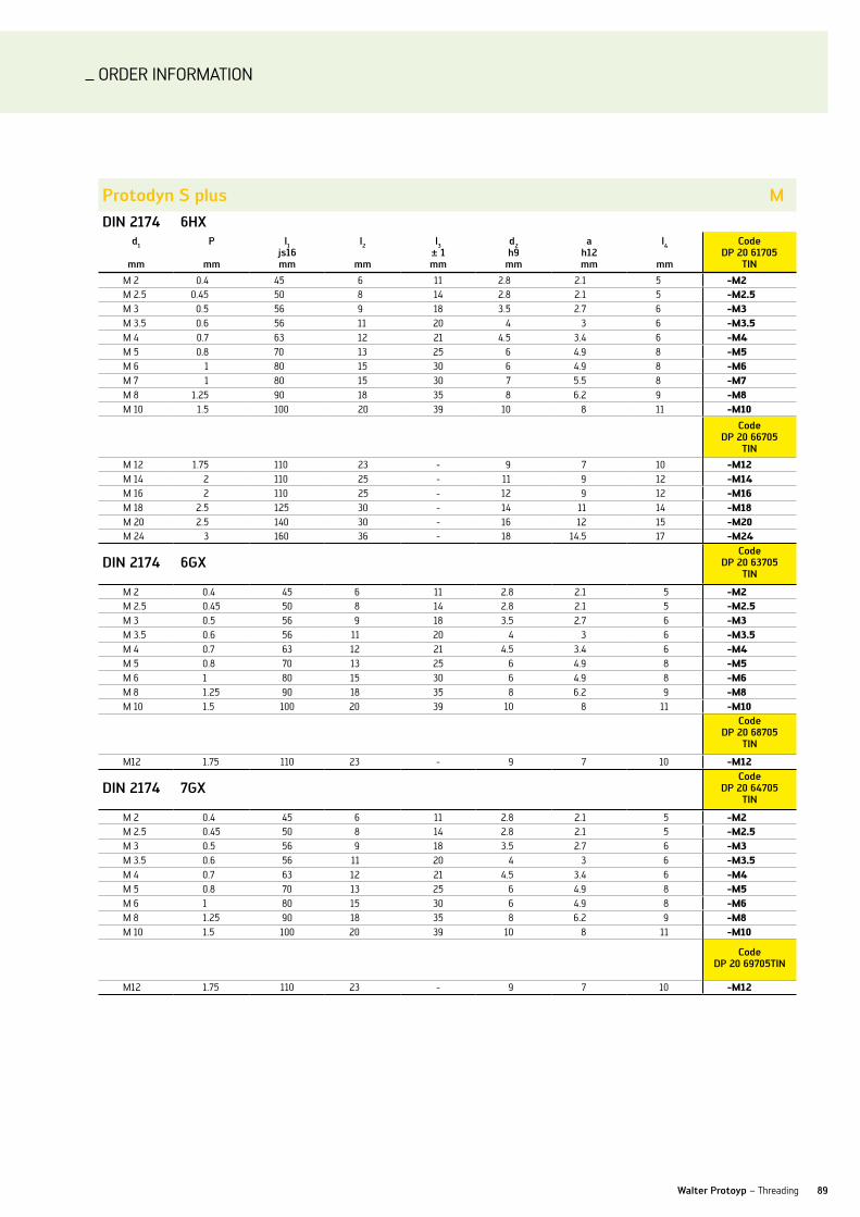
ORDER InFORMATIOn
89Walter Protoyp – Threading
Protodyn s plus MDin 2174 6hx
d1
mm
P
mm
l1js16mm
l2
mm
l3± 1mm
d2h9
mm
ah12mm
l4
mm
codeDP 20 61705
Tin
M 2 0.4 45 6 11 2.8 2.1 5 -M2 M 2.5 0.45 50 8 14 2.8 2.1 5 -M2.5 M 3 0.5 56 9 18 3.5 2.7 6 -M3 M 3.5 0.6 56 11 20 4 3 6 -M3.5 M 4 0.7 63 12 21 4.5 3.4 6 -M4 M 5 0.8 70 13 25 6 4.9 8 -M5 M 6 1 80 15 30 6 4.9 8 -M6 M 7 1 80 15 30 7 5.5 8 -M7 M 8 1.25 90 18 35 8 6.2 9 -M8 M 10 1.5 100 20 39 10 8 11 -M10
codeDP 20 66705
Tin
M 12 1.75 110 23 - 9 7 10 -M12M 14 2 110 25 - 11 9 12 -M14M 16 2 110 25 - 12 9 12 -M16M 18 2.5 125 30 - 14 11 14 -M18M 20 2.5 140 30 - 16 12 15 -M20M 24 3 160 36 - 18 14.5 17 -M24
Din 2174 6gxcode
DP 20 63705Tin
M 2 0.4 45 6 11 2.8 2.1 5 -M2 M 2.5 0.45 50 8 14 2.8 2.1 5 -M2.5 M 3 0.5 56 9 18 3.5 2.7 6 -M3 M 3.5 0.6 56 11 20 4 3 6 -M3.5 M 4 0.7 63 12 21 4.5 3.4 6 -M4 M 5 0.8 70 13 25 6 4.9 8 -M5 M 6 1 80 15 30 6 4.9 8 -M6 M 8 1.25 90 18 35 8 6.2 9 -M8 M 10 1.5 100 20 39 10 8 11 -M10
codeDP 20 68705
Tin
M12 1.75 110 23 - 9 7 10 -M12
Din 2174 7gxcode
DP 20 64705Tin
M 2 0.4 45 6 11 2.8 2.1 5 -M2 M 2.5 0.45 50 8 14 2.8 2.1 5 -M2.5 M 3 0.5 56 9 18 3.5 2.7 6 -M3 M 3.5 0.6 56 11 20 4 3 6 -M3.5 M 4 0.7 63 12 21 4.5 3.4 6 -M4 M 5 0.8 70 13 25 6 4.9 8 -M5 M 6 1 80 15 30 6 4.9 8 -M6 M 8 1.25 90 18 35 8 6.2 9 -M8 M 10 1.5 100 20 39 10 8 11 -M10
codeDP 20 69705Tin
M12 1.75 110 23 - 9 7 10 -M12

ORDER InFORMATIOn
90
Protodyn s plus MfDin 2174 6hx
d1
mm
P
mm
l1js16mm
l2
mm
l3± 1mm
d2h9
mm
ah12mm
l4
mm
codeDP 21 61705
Tin
M 4 0.5 63 12 21 4.5 3.4 6 -M4X0.5M 5 0.5 70 13 25 6 4.9 8 -M5X0.5M 6 0.5 80 15 30 6 4.9 8 -M6X0.5M 6 0.75 80 15 30 6 4.9 8 -M6X0.75M 7 0.75 80 15 30 7 4.9 8 -M7X0.75
codeDP 21 66705
Tin
M 8 0.5 80 15 - 6 5.5 8 -M8X0.5 M 8 0.75 80 15 - 6 4.9 8 -M8X0.75 M 8 1 90 18 - 6 4.9 8 -M8X1 M 10 1 90 20 - 7 5.5 8 -M10X1 M 10 1.25 100 20 - 7 5.5 8 -M10X1.25 M 12 1 100 21 - 9 7 10 -M12X1 M 12 1.25 100 21 - 9 7 10 -M12X1.25 M 12 1.5 100 21 - 9 7 10 -M12X1.5 M 14 1.5 100 21 - 11 9 12 -M14X1.5 M 16 1.5 100 21 - 12 9 12 -M16X1.5 M 18 1.5 110 24 - 14 11 14 -M18X1.5 M 20 1.5 125 24 - 16 12 15 -M20X1.5 M 22 1.5 125 24 - 18 14.5 17 -M22X1.5 M 24 1.5 140 26 - 18 14.5 17 -M24X1.5

ORDER InFORMATIOn
91Walter Protoyp – Threading
Protodyn s plus uncDin 2184-1 2bx
d1-P
nom
d1
mm
l1js16mm
l2
mm
l3± 1mm
d2h9
mm
ah12mm
l4
mm
codeDP 22 61705
Tin
no. 2-56 2.184 45 7 12 2.8 2.1 5 -UNC2no. 4-40 2.845 56 9 18 3.5 2.7 6 -UNC4no. 6-32 3.505 56 11 20 4 3 6 -UNC6no. 8-32 4.166 63 12 21 4.5 3.4 6 -UNC8no. 10-24 4.826 70 13 25 6 4.9 8 -UNC101/4-20 6.350 80 15 30 7 5.5 8 -UNC1/45/16-18 7.938 90 18 35 8 6.2 9 -UNC5/163/8-16 9.525 100 20 39 10 8 11 -UNC3/8
codeDP 22 66705
Tin
7/16-14 11.113 100 20 - 8 6.2 9 -UNC7/161/2-13 12.700 110 23 - 9 7 10 -UNC1/25/8-11 15.875 110 25 - 12 9 12 -UNC5/8
Protodyn s plus unfDin 2184-1 2bx
d1-P
nom
d1
mm
l1js16mm
l2
mm
l3± 1mm
d2h9
mm
ah12mm
l4
mm
codeDP 23 61705
Tin
no. 2-64 2.184 45 7 12 2.8 2.1 5 -UNF2no. 4-48 2.845 56 9 18 3.5 2.7 6 -UNF4no. 6-40 3.505 56 11 20 4 3 6 -UNF6no. 8-36 4.166 63 12 21 4.5 3.4 6 -UNF8no. 10-32 4.826 70 13 25 6 4.9 8 -UNF101/4-28 6.350 80 15 30 7 5.5 8 -UNF1/45/16-24 7.938 90 18 35 8 6.2 9 -UNF5/163/8-24 9.525 100 20 39 10 8 11 -UNF3/8
codeDP 23 66705
Tin
7/16-20 11.113 100 20 - 8 6.2 9 -UNF7/161/2-20 12.700 110 21 - 9 7 10 -UNF1/25/8-18 15.875 110 21 - 12 9 12 -UNF5/8
Protodyn s plus gDin 2189 g-x
d1
nom
d1
mm
l1js16mm
l2
mm
l3± 1mm
d2h9
mm
ah12mm
l4
mm
codeDP 24 66705
Tin
★ G1/8 2.184 45 7 12 2.8 2.1 5 g1/8★ G1/4 2.845 56 9 18 3.5 2.7 6 g1/4★ G3/8 3.505 56 11 20 4 3 6 g3/8★ G1/2 4.166 63 12 21 4.5 3.4 6 g1/2★ G3/4 4.826 70 13 25 6 4.9 8 g3/4★ G1 6.350 80 15 30 7 5.5 8 g1
NEW2010
★ new addition to range

hss-E tap without internal cooling
Prototex Tini plus – through hole MDin 371 6hx
d1
mm
P
mm
l1js16mm
l2
mm
l3± 1mm
d2h9
mm
ah12mm
l4
mmn
code 20 21763
acn
M 2 0.4 45 8 - 2.8 2.1 5 2 -M2 M 2.5 0.45 50 9 - 2.8 2.1 5 2 -M2.5 M 3 0.5 56 10 - 3.5 2.7 6 2 -M3 M 3.5 0.6 56 12 - 4 3 6 3 -M3.5 M 4 0.7 63 13 - 4.5 3.4 6 3 -M4 M 5 0.8 70 16 - 6 4.9 8 3 -M5 M 6 1 80 15 23 6 4.9 8 3 -M6 M 8 1.25 90 18 29.5 8 6.2 9 3 -M8 M 10 1.5 100 20 33.5 10 8 11 3 -M10
Din 376 6hxcode
20 26763acn
M 12 1.75 110 23 - 9 7 10 4 -M12M 16 2 110 25 - 12 9 12 4 -M16M 20 2.5 140 30 - 16 12 15 4 -M20
ORDER InFORMATIOn
92
Prototex Tini plus – through hole Mf
~ Din 371 6hx
d1
mm
P
mm
l1js16mm
l2
mm
l3± 1mm
d2h9
mm
ah12mm
l4
mmn
code 21 21763
acn
M 6 0.75 80 15 23 6 4.9 8 3 -M6X0.75 M 8 0.75 90 18 29.5 8 6.2 9 3 -M8X0.75 M 8 1 90 18 29.5 8 6.2 9 3 -M8X1 M 10 1 100 20 33.5 10 8 11 3 -M10X1
Din 374 6hxcode
21 26763acn
M 12 1 100 21 - 9 7 10 4 -M12X1M 12 1.5 100 21 - 9 7 10 4 -M12X1.5M 14 1.5 100 21 - 11 9 12 4 -M14X1.5
Paradur Ti plus – blind hole M~ Din 371 6hx
d1
mm
P
mm
l1js16mm
l2
mm
l3± 1mm
d2h9
mm
ah12mm
l4
mmn
code 20 41663
acn
M 2 0.4 45 8 - 2.8 2.1 5 3 -M2 M 2.5 0.45 50 9 - 2.8 2.1 5 3 -M2.5 M 3 0.5 56 10 - 3.5 2.7 6 3 -M3 M 3.5 0.6 56 12 - 4 3 6 3 -M3.5 M 4 0.7 63 13 - 4.5 3.4 6 3 -M4 M 5 0.8 70 16 - 6 4.9 8 3 -M5 M 6 1 80 15 23 6 4.9 8 3 -M6 M 8 1.25 90 18 29.5 8 6.2 9 3 -M8 M 10 1.5 100 20 33.5 10 8 11 3 -M10
Din 376 6hxcode
20 46663acn
M 12 1.75 110 23 - 9 7 10 4 -M12M 16 2 110 25 - 12 9 12 4 -M16M 20 2.5 140 30 - 16 12 15 4 -M20

ORDER InFORMATIOn
93Walter Protoyp – Threading
Paradur Ti plus – blind hole Mf~ Din 371 6hx
d1
mm
P
mm
l1js16mm
l2
mm
l3± 1mm
d2h9
mm
ah12mm
l4
mmn
code 21 41663
acn
M6 0.75 80 15 23 6 4.9 8 3 -M6X0.75 M8 0.75 90 18 29.5 8 6.2 9 3 -M8X0.75 M8 1 90 18 29.5 8 6.2 9 3 -M8X1 M10 1 100 20 33.5 10 8 11 3 -M10X1
Din 374 6hxcode
21 46663acn
M 12 1 100 21 - 9 7 10 4 -M12X1M 12 1.5 100 21 - 9 7 10 4 -M12X1.5M 14 1.5 100 21 - 11 9 12 4 -M14X1.5
Paradur hsc – blind hole MfDin 371 6hx
d1
mm
P
mm
l1js16mm
l2
mm
l3± 1mm
d2h9
mm
ah12mm
l4
mm
n code81 41056
Ticn
M 6 0.75 80 15 - 6 4.9 8 3 -M6X0.75 M 8 1 90 20 - 8 6.2 9 3 -M8X1 M 10 1 90 25 - 10 8 11 3 -M10X1
Din 374 6hxcode
81 46056Ticn
M 12 1 100 20 - 9 7 10 3 -M12X1M 12 1.5 100 20 - 9 7 10 4 -M12X1.5M 14 1.5 100 21 - 11 9 12 4 -M14X1.5M 16 1.5 100 21 - 12 9 12 4 -M16X1.5
solid carbide taps
Paradur hsc – blind hole MDin 371 6hx
d1
mm
P
mm
l1js16mm
l2
mm
l3± 1mm
d2h9
mm
ah12mm
l4
mm
n code80 41056
Ticn
M 6 1 80 15 30 6 4.9 8 3 -M6M 8 1.25 90 20 35 8 6.2 9 3 -M8M 10 1.5 100 25 39 10 8 11 3 -M10
Din 376 6hxcode
80 46056Ticn
M 12 1.75 110 23 - 9 7 10 4 -M12
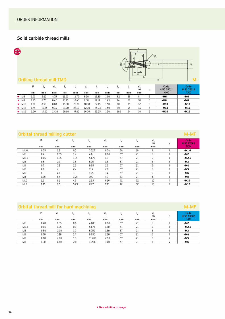
ORDER InFORMATIOn
94
solid carbide thread mills
Drilling thread mill TMD MP
mm
d1
mm
d3
mm
l2
mm
l6
mm
d4
mm
l4
mm
l5
mm
l1
mm
lk
mm
d2h6
mmz
codeh 50 75011
nhc
codeh 50 75018
Tax
★ M6 1.00 5.00 4.75 11.00 14.70 6.30 13.80 1.00 62 26 8 3 -M6 -M6★ M8 1.25 6.75 6.42 13.75 18.40 8.30 17.17 1.25 74 34 10 3 -M8 -M8★ M10 1.50 8.50 8.08 18.00 23.70 10.30 22.15 1.50 80 35 12 3 -M10 -M10★ M12 1.75 10.25 9.74 21.00 27.10 12.30 25.23 1.50 90 45 14 3 -M12 -M12★ M16 2.00 14.00 13.30 30.00 37.60 16.30 35.05 1.50 102 54 18 3 -M16 -M16
★ new addition to range
orbital thread mill for hard machining M-MfP
mm
d1
mm
l2
mm
l3
mm
d3
mm
l1
mm
lk
mm
d2h6
mmz
codeh 50 83008
Tax
M2 0.40 1.55 0.8 4.600 0.98 57 21 6 3 -M2 M2.5 0.45 1.95 0.9 5.675 1.30 57 21 6 3 -M2.5 M3 0.50 2.30 1.0 6.750 1.60 57 21 6 3 -M3 M4 0.70 3.10 1.4 9.050 2.10 57 21 6 3 -M4M5 0.80 4.00 1.6 11.200 2.90 57 21 6 4 -M5M6 1.00 4.80 2.0 13.500 3.40 57 21 6 4 -M6
orbital thread milling cutter M-MfP
mm
d1
mm
l2
mm
l3
mm
d3
mm
l1
mm
lk
mm
d2h6
mmz
codeh 50 87006
Ticn
M1.6 0.35 1.2 0.7 3.725 0.74 38 10 3 3 -M1.6 M2 0.4 1.55 1.2 4.6 0.98 57 21 6 3 -M2 M2.5 0.45 1.95 1.35 5.675 1.3 57 21 6 3 -M2.5 M3 0.5 2.3 1.5 6.75 1.6 57 21 6 3 -M3 M4 0.7 3.1 2.1 9.05 2.1 57 21 6 3 -M4 M5 0.8 4 2.4 11.2 2.9 57 21 6 3 -M5 M6 1 4.8 3 13.5 3.4 57 21 6 3 -M6 M8 1.25 6.4 3.75 19.7 4.7 63 21 8 3 -M8M10 1.5 8.2 4.5 22.3 6.16 72 32 10 4 -M10M12 1.75 9.5 5.25 26.7 7.13 72 32 10 5 -M12
NEW2010

Drilling. ThrEaDing. ExacTly!
ww
w.k
raas
-lac
hman
n.co
m
To produce the perfect thread, you need perfectly compatible high-performance tools. With this tool duo from Walter Titex and Walter Prototyp, you get twice the expertise, safe processes and maximum efficiency for your manufacturing needs.
Expect more. Engineer what you envision.

Turning
Drilling & ThrEaDing
Milling
Walter 3ISO indexable inserts 4 and 12ISO turning toolholders 6 and 19Grooving 10 and 22Order information 24
Walter Titex 41Solid carbide drills 42PCD drill 46Order information 48
Walter 55Boring tools 56Reaming inserts 58Indexable & Point Drills 60Order information 66
Walter Prototyp 75Solid carbide thread milling cutters 76HSS thread former 79Solid carbide taps 82Order information 84
Walter Prototyp 97Solid carbide end mills 98Order information 104
Walter 125Cutting tool materials 126 and 140Face, shoulder, slot and copy mills 128 and 142Order information 152
Alphanumeric index 170

_TOOl InnOvATIOnS In MIllInG
conefit™ for optimum flexibility.
Product innovations Edition 2010-1
Milling

98
SOlID CARBIDE EnD MIll
Walter Prototyp Proto·max™sTsolid carbide high performance end mill for machining steel.
ThE Tool
Solid carbide high performance end mill specially –for machining steel materialsWith and without corner radius –Diameter range of 2 to 20 and 1/16" to 3/4" –From R = 0.2 up to 4 mm –Helix angle – = 45° and 50°Reinforced core diameter –large core diameter –3 and 4 cutting edges –Shank in accordance with DIn 6535 HA –With reduced neck (d – 3) and back cuttingTAZ coating –
aPPlicaTions
Primary application –ISO material group P Secondary application –ISO material group MFor roughing and finishing –When a high machining volume is required –Full grooves of 2xd – 1 (z=3) and 1.5xd1 (z=4)Pocket milling, inclined plunging and contour – millingFor use in general engineering, automotive – industries and mould and die making
your aDvanTagEs
Maximum machining volume of up to 50 % more in com- –parison with the usual 3- and 4-edge tools on the marketlarge feed up to 2xd – 1 in steel materialsuneven tooth spacing for low spindle stress –Soft cutting action and optimum chip evacuation –thanks to large helix angle Can be used for dry and wet machining –Increased tool life with the latest TAZ coating –Back cutting, reduces transitions with side end – machining on the workpieceHigh process stability thanks to stable core and – optimised microgeometry
Proto·max™sT high-performance end mill H4033217 metric H4036217 metric – with protection radius AH4033217 inch
Shank with special surface treatment for a better grip > Ø 10 mm
45° helix angle for a soft cutting action
Optimised microgeometry for stable cutting edge
3 cutting edges
NEW2010
Back cutting
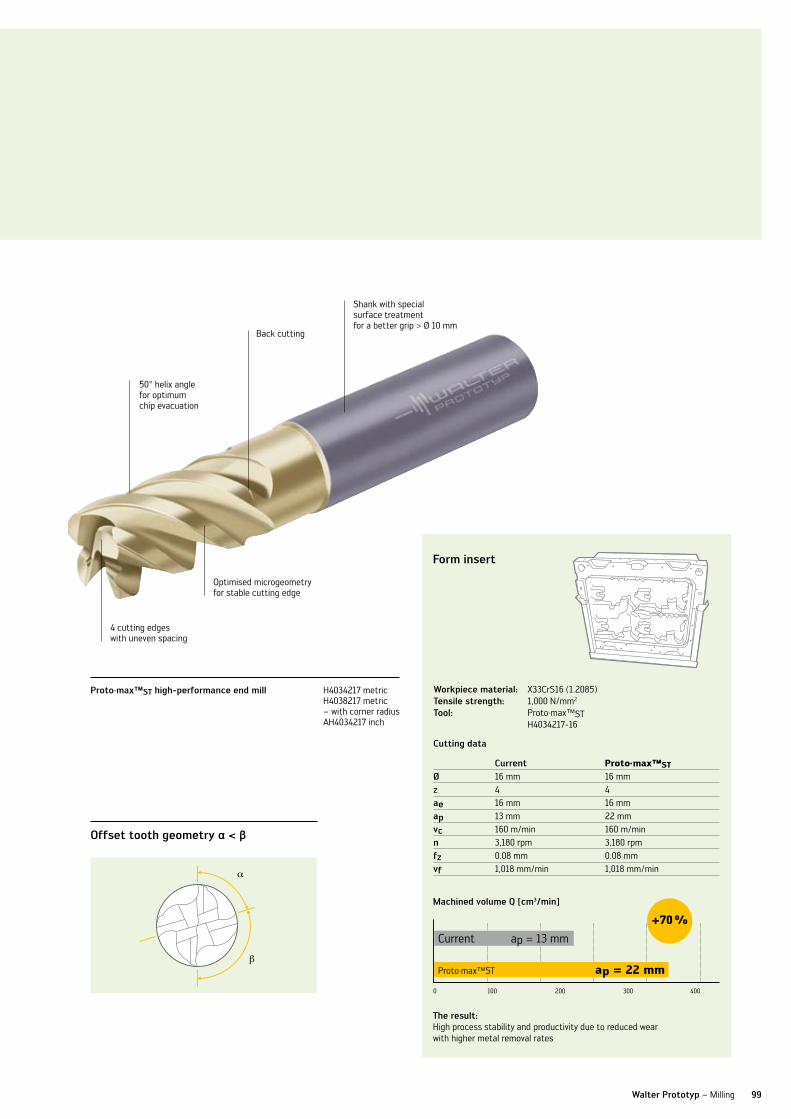
99Walter Prototyp – Milling
Proto·max™sT high-performance end mill H4034217 metric H4038217 metric – with corner radius AH4034217 inch
Shank with special surface treatment for a better grip > Ø 10 mm
50° helix angle for optimum chip evacuation
Optimised microgeometry for stable cutting edge
4 cutting edges with uneven spacing
form insert
cutting data
current Proto·max™STØ 16 mm 16 mmz 4 4ae 16 mm 16 mmap 13 mm 22 mmvc 160 m/min 160 m/minn 3,180 rpm 3,180 rpmfz 0.08 mm 0.08 mmvf 1,018 mm/min 1,018 mm/min
Machined volume q [cm3/min]
0 100 200 300 400
Current
Proto·max™ST ap = 22 mm
+70 %
ap = 13 mm
Workpiece material: X33CrS16 (1.2085)Tensile strength: 1,000 n/mm2
Tool: Proto·max™ST H4034217-16
The result:High process stability and productivity due to reduced wear with higher metal removal rates
offset tooth geometry α < β
Back cutting
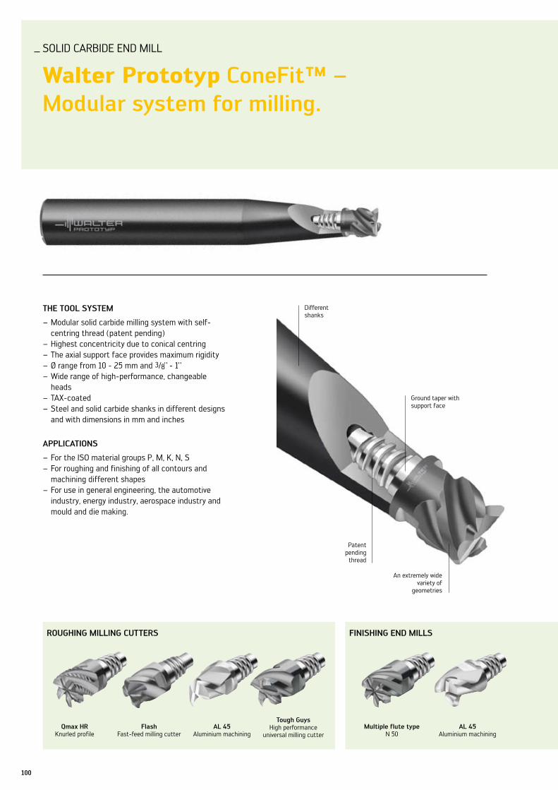
100
roughing Milling cuTTErs finishing EnD Mills
Walter Prototyp – Milling
SOlID CARBIDE EnD MIll
Walter Prototyp conefit™ – Modular system for milling.
ThE Tool sysTEM
Modular solid carbide milling system with self- –centring thread (patent pending)Highest concentricity due to conical centring –The axial support face provides maximum rigidity –Ø range from 10 - 25 mm and – 3/8 - 1Wide range of high-performance, changeable –headsTAX-coated –Steel and solid carbide shanks in different designs –and with dimensions in mm and inches
aPPlicaTions
For the ISO material groups P, M, K, n, S –For roughing and finishing of all contours and –machining different shapesFor use in general engineering, the automotive –industry, energy industry, aerospace industry and mould and die making.
Different shanks
Ground taper with support face
An extremely wide variety of
geometries
Patent pending
thread
qmax hrKnurled profile
flashFast-feed milling cutter
al 45Aluminium machining
Tough guysHigh performance
universal milling cutterMultiple flute type
n 50al 45
Aluminium machining

101
finishing EnD Mills 3-D conTour Milling cuTTEr ProfilE Milling cuTTEr
Walter Prototyp – Milling
your aDvanTagEs
ConeFit™ is flexible and –can be used for any type of machining Modular design with – different shank variantsExtremely wide variety –of tool geometriesMaximum stability –and precision thanks to surface and taper contact with patented self-centring threadReduction in inventory –costs thanks to very flexible and universal tooling systemHighly productive –machining thanks to extremely high rigidity
Type a straight version with reinforced shank
Tough guysHigh performance
universal milling cutterball-nose end mill
n 40flash
High Feed milling cutterchamfer
milling cutter60° / 90° / 120°
corner rounding end mill
Type a straight version
Type b 89° version
Type c 85° version
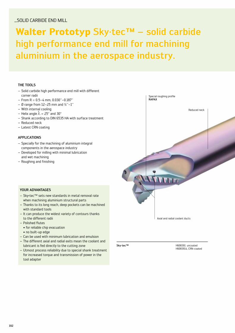
SuBlInE üBER HEADlInE (1.1)
headline in grün (1.2), auch für umbrüche als 3- Zeiler möglich. headline in grün, auch für umbrüche als 3- Zeiler möglich.
102
SOlID CARBIDE EnD MIll
Walter Prototyp sky·tec™ – solid carbide high performance end mill for machining aluminium in the aerospace industry.
ThE Tools
Solid carbide high performance end mill with different –corner radiiFrom R = 0.5–4 mm; 0.030''–0.187'' –Ø range from 12–25 mm and ½''–1'' –With internal cooling –Helix angle – = 25° and 30°Shank according to DIn 6535 HA with surface treatment –Reduced neck –latest CRn coating –
aPPlicaTions
Specially for the machining of aluminium integral – components in the aerospace industryDeveloped for milling with minimal lubrication –and wet machiningRoughing and finishing –
your aDvanTagEs
Sky – ·tec™ sets new standards in metal removal rate when machining aluminium structural partsThanks to its long reach, deep pockets can be machined –with standard toolsIt can produce the widest variety of contours thanks –to the different radiiPolished flutes –•forreliablechipevacuation •nobuilt-upedgeCan be used with minimum lubrication and emulsion –The different axial and radial exits mean the coolant and –lubricant is fed directly to the cutting zone utmost process reliability due to special shank treatment –for increased torque and transmission of power in the tool adapter
Special roughing profile raPax
Reduced neck
Axial and radial coolant ducts
sky·tec™ H608391. uncoated H6083914, CRn-coated
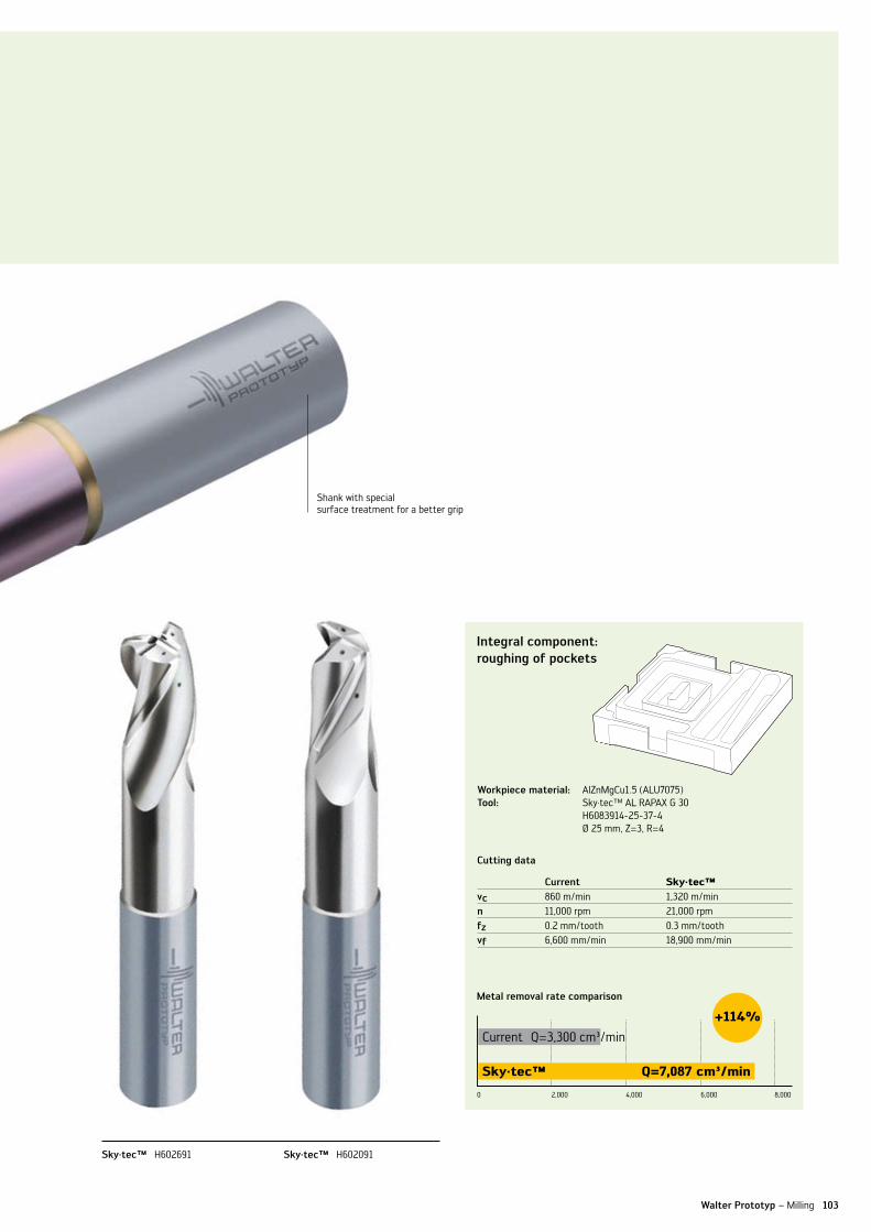
103Walter Prototyp – Milling
Shank with special surface treatment for a better grip
sky·tec™ H602691 sky·tec™ H602091
integral component: roughing of pockets
cutting data
current Sky·tec™vc 860 m/min 1,320 m/minn 11,000 rpm 21,000 rpmfz 0.2 mm/tooth 0.3 mm/toothvf 6,600 mm/min 18,900 mm/min
Metal removal rate comparison
0 2,000 4,000 6,000 8,000
Current
Sky·tec™ Q=7,087 cm³/min
+114%
Q=3,300 cm³/min
Workpiece material: AlZnMgCu1.5 (Alu7075)Tool: Sky·tec™ Al RAPAX G 30
H6083914-25-37-4Ø 25 mm, Z=3, R=4

ORDER InFORMATIOn
104
Proto·max™sT high-performance end mill
Proto·max™sT - 3-edge – metricd1
h9mm
l2
mm
l3
mm
d3
mm
l1
mm
lk
mm
d2
h6mm
z codeh40 33217
TaZ
★ 2 5 7.5 1.92 57 21 6 3 -2
★ 3 7 10.5 2.9 57 21 6 3 -3
★ 4 9 15 3.8 57 21 6 3 -4
★ 5 11 16 4.75 57 21 6 3 -5
★ 6 13 19 5.7 57 21 6 3 -6
★ 8 18 25 7.6 63 27 8 3 -8
★ 10 22 30 9.5 72 32 10 3 -10
★ 12 26 36 11.4 83 38 12 3 -12
★ 16 34 42 15.2 92 44 16 3 -16
★ 20 42 52 19 104 54 20 3 -20
Proto·max™sT - 3-edge – inchesd1
h9inch
l2
inch
l3
inch
d3
inch
l1
inch
lk
inch
d2
h6inch
z codeah40 33217
TaZ
★ 1/16 0.164 0.246 0.059 2.000 0.582 0.250 3 -1/16
★ 3/32 0.227 0.340 0.089 2.500 1.437 0.250 3 -3/32
★ 1/8 0.289 0.434 0.119 2.500 1.437 0.250 3 -1/8
★ 3/16 0.414 0.622 0.178 2.500 1.437 0.250 3 -3/16
★ 1/4 0.539 0.809 0.237 3.000 1.437 0.375 3 -1/4
★ 5/16 0.664 0.997 0.297 3.000 1.437 0.375 3 -5/16
★ 3/8 0.829 1.243 0.356 3.000 1.437 0.375 3 -3/8
★ 7/16 0.954 1.431 0.416 3.500 1.717 0.500 3 -7/16
★ 1/2 1.079 1.431 0.475 3.500 1.717 0.500 3 -1/2
★ 5/8 1.329 1.535 0.594 3.500 1.594 0.625 3 -5/8
★ 3/4 1.579 1.890 0.713 4.000 1.969 0.750 3 -3/4
Proto·max™sT - 3-edge with protection radius – metricd1
h9mm
l2
mm
r
mm
l3
mm
d3
mm
l1
mm
lk
mm
d2
h6mm
z codeh40 36217
TaZ
★ 2 5 0.08 7.5 1.92 57 21 6 3 -2
★ 3 7 0.08 10.5 2.9 57 21 6 3 -3
★ 4 9 0.08 15 3.8 57 21 6 3 -4
★ 5 11 0.16 16 4.75 57 21 6 3 -5
★ 6 13 0.16 19 5.7 57 21 6 3 -6
★ 8 18 0.16 25 7.6 63 27 8 3 -8
★ 10 22 0.25 30 9.5 72 32 10 3 -10
★ 12 26 0.25 36 11.4 83 38 12 3 -12
★ 16 34 0.25 42 15.2 92 44 16 3 -16
★ 20 42 0.4 52 19 104 54 20 3 -20
NEW2010
NEW2010
NEW2010
★ new addition to range

ORDER InFORMATIOn
105Walter Prototyp – Milling
Proto·max™sT - 4-edge – metricd1
h9mm
l2
mm
l3
mm
d3
mm
l1
mm
lk
mm
d2
h6mm
z codeh40 34217
TaZ
★ 3 5 8.5 2.9 57 21 6 4 -3
★ 4 7 11 3.8 57 21 6 4 -4
★ 5 8 14 4.75 57 21 6 4 -5
★ 6 10 16 5.7 57 21 6 4 -6
★ 8 13 22 7.6 63 27 8 4 -8
★ 10 16 28 9.5 72 32 10 4 -10
★ 12 19 33 11.4 83 38 12 4 -12
★ 14 22 36 13.3 83 38 14 4 -14
★ 16 26 42 15.2 92 44 16 4 -16
★ 18 29 42 17.1 92 44 18 4 -18
★ 20 32 52 19 104 54 20 4 -20
Proto·max™sT - 4-edge – inchesd1
h9inch
l2
inch
l3
inch
d3
inch
l1
inch
lk
inch
d2
h6inch
z codeah40 34217
TaZ
★ 1/4 0.405 0.608 0.237 3.000 1.437 0.375 4 - 1/4
★ 5/16 0.506 0.760 0.297 3.000 1.437 0.375 4 - 5/16
★ 3/8 0.608 0.911 0.356 3.000 1.437 0.375 4 - 3/8
★ 7/16 0.709 1.063 0.416 3.500 1.717 0.500 4 - 7/16
★ 1/2 0.810 1.215 0.475 3.500 1.717 0.500 4 - 1/2
★ 5/8 1.013 1.519 0.594 3.500 1.594 0.625 4 - 5/8
★ 3/4 1.215 1.823 0.713 4.000 1.969 0.750 4 - 3/4
Proto·max™sT - 4-edge with corner radius – metricd1
h9mm
l2
mm
r
mm
l3
mm
d3
mm
l1
mm
lk
mm
d2
h6mm
z codeh40 38217
TaZ
★ 3 5 0.2 8.5 2.9 57 21 6 4 -3-0,2
★ 3 5 0.5 8.5 2.9 57 21 6 4 -3-0,5
★ 4 7 0.2 11 3.8 57 21 6 4 -4-0,2
★ 4 7 0.5 11 3.8 57 21 6 4 -4-0,5
★ 5 8 0.5 14 4.75 57 21 6 4 -5-0,5
★ 5 8 1 14 4.75 57 21 6 4 -5-1
★ 6 10 0.5 16 5.7 57 21 6 4 -6-0,5
★ 6 10 1 16 5.7 57 21 6 4 -6-1
★ 8 13 0.5 22 7.6 63 27 8 4 -8-0,5
★ 8 13 1 22 7.6 63 27 8 4 -8-1
★ 8 13 2 22 7.6 63 27 8 4 -8-2
★ 10 16 0.5 28 9.5 72 32 10 4 -10-0,5
★ 10 16 1 28 9.5 72 32 10 4 -10-1
★ 10 16 2 28 9.5 72 32 10 4 -10-2
★ 12 19 0.5 33 11.4 83 38 12 4 -12-0,5
★ 12 19 1 33 11.4 83 38 12 4 -12-1
★ 12 19 2 33 11.4 83 38 12 4 -12-2
★ 16 26 0.5 42 15.2 92 44 16 4 -16-0,5
★ 16 26 1 42 15.2 92 44 16 4 -16-1
★ 16 26 2 42 15.2 92 44 16 4 -16-2
★ 20 32 1 52 19 104 54 20 4 -20-1
★ 20 32 2 52 19 104 54 20 4 -20-2
★ 20 32 4 52 19 104 54 20 4 -20-4
NEW2010
NEW2010
NEW2010
★ new addition to range

ORDER InFORMATIOn
106
roughing milling cutters
qmax hr kordel f 40 - conefit™ – metricd1
h12mm
l2
mm
l3E
mm
d3
mm
z sW
mm
E codeh3E 82 378
Tax
10 5.5 12.4 9.7 4 8 10 -E10-10
12 6.5 14.5 11.7 4 10 12 -E12-12
16 8.5 18.7 15.5 4 12 16 -E16-16
qmax hr kordel f 40 - conefit™ – inchesd1
h12inch
l2
inch
l3E
inch
d3
inch
z sW
mm
E codeah3E 82 378
Tax
3/8 0.209 0.488 0.364 4 8 10 -E10-3/8
1/2 0.276 0.575 0.484 4 10 12 -E12-1/2
5/8 0.335 0.736 0.610 4 12 16 -E16-5/8
qmax hr kordel f 45 - conefit™ – metricd1
h12mm
l2
mm
l3E
mm
d3
mm
z sW
mm
E codeh3E 85 378
Tax
12 6.5 14.5 11.7 5 10 12 -E12-12
16 8.5 18.7 15.5 6 12 16 -E16-16
20 11 21.3 19.3 6 16 20 -E20-20
25 13 25.6 24.2 8 20 25 -E25-25
qmax hr kordel f 45 - conefit™ – inchesd1
h12inch
l2
inch
l3E
inch
d3
inch
z sW
mm
E codeah3E 85 378
Tax
3/8 0.209 0.488 0.364 6 8 10 -E10-3/8
1/2 0.276 0.575 0.484 6 10 12 -E12-1/2
5/8 0.335 0.736 0.610 6 12 16 -E16-5/8
3/4 0.413 0.839 0.728 6 16 20 -E20-3/4
★ 1 0.551 1.008 0.965 8 20 25 -E25-1
★ new addition to range
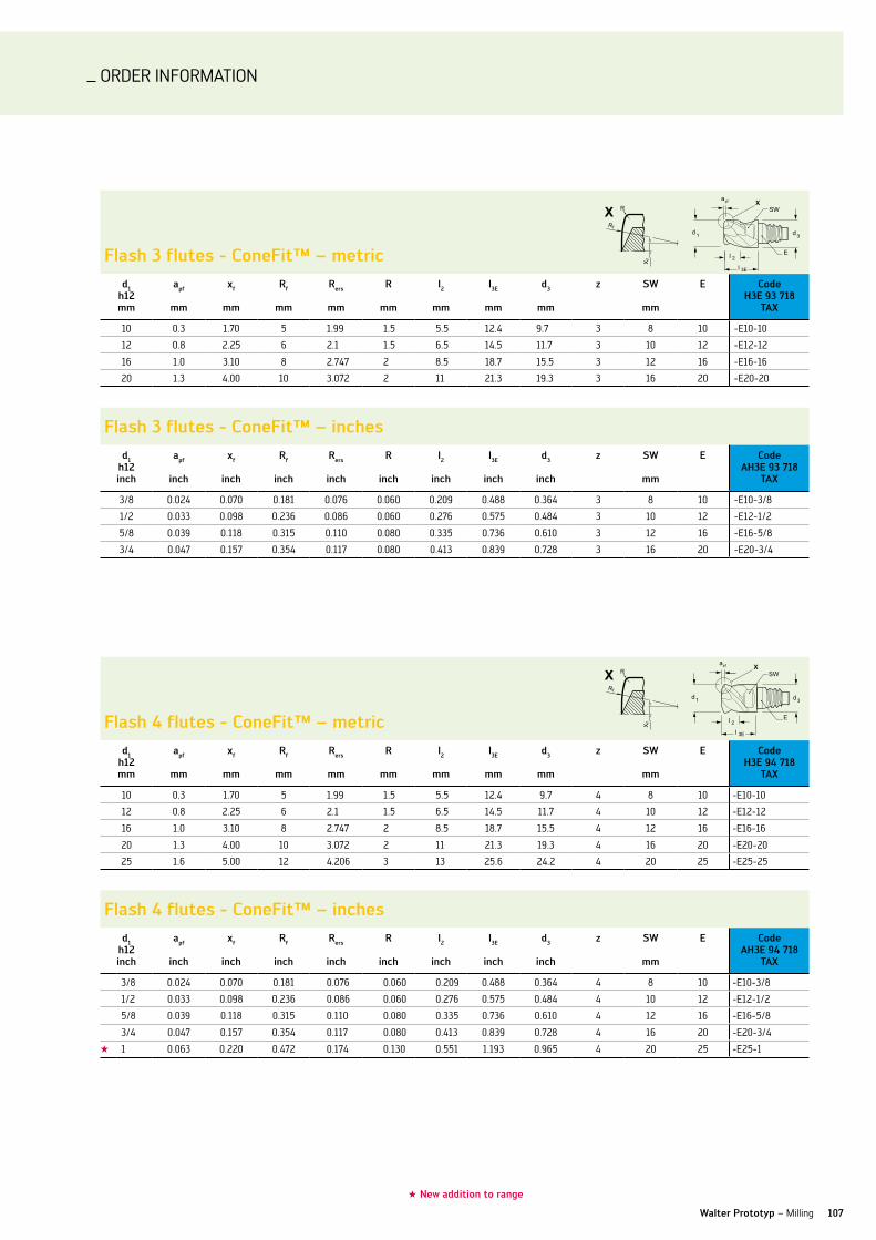
ORDER InFORMATIOn
107Walter Prototyp – Milling
flash 4 flutes - conefit™ – metricd1
h12mm
apf
mm
xf
mm
rf
mm
rers
mm
r
mm
l2
mm
l3E
mm
d3
mm
z sW
mm
E codeh3E 94 718
Tax
10 0.3 1.70 5 1.99 1.5 5.5 12.4 9.7 4 8 10 -E10-10
12 0.8 2.25 6 2.1 1.5 6.5 14.5 11.7 4 10 12 -E12-12
16 1.0 3.10 8 2.747 2 8.5 18.7 15.5 4 12 16 -E16-16
20 1.3 4.00 10 3.072 2 11 21.3 19.3 4 16 20 -E20-20
25 1.6 5.00 12 4.206 3 13 25.6 24.2 4 20 25 -E25-25
flash 4 flutes - conefit™ – inchesd1
h12inch
apf
inch
xf
inch
rf
inch
rers
inch
r
inch
l2
inch
l3E
inch
d3
inch
z sW
mm
E codeah3E 94 718
Tax
3/8 0.024 0.070 0.181 0.076 0.060 0.209 0.488 0.364 4 8 10 -E10-3/8
1/2 0.033 0.098 0.236 0.086 0.060 0.276 0.575 0.484 4 10 12 -E12-1/2
5/8 0.039 0.118 0.315 0.110 0.080 0.335 0.736 0.610 4 12 16 -E16-5/8
3/4 0.047 0.157 0.354 0.117 0.080 0.413 0.839 0.728 4 16 20 -E20-3/4
★ 1 0.063 0.220 0.472 0.174 0.130 0.551 1.193 0.965 4 20 25 -E25-1
flash 3 flutes - conefit™ – metricd1
h12mm
apf
mm
xf
mm
rf
mm
rers
mm
r
mm
l2
mm
l3E
mm
d3
mm
z sW
mm
E codeh3E 93 718
Tax
10 0.3 1.70 5 1.99 1.5 5.5 12.4 9.7 3 8 10 -E10-10
12 0.8 2.25 6 2.1 1.5 6.5 14.5 11.7 3 10 12 -E12-12
16 1.0 3.10 8 2.747 2 8.5 18.7 15.5 3 12 16 -E16-16
20 1.3 4.00 10 3.072 2 11 21.3 19.3 3 16 20 -E20-20
flash 3 flutes - conefit™ – inchesd1
h12inch
apf
inch
xf
inch
rf
inch
rers
inch
r
inch
l2
inch
l3E
inch
d3
inch
z sW
mm
E codeah3E 93 718
Tax
3/8 0.024 0.070 0.181 0.076 0.060 0.209 0.488 0.364 3 8 10 -E10-3/8
1/2 0.033 0.098 0.236 0.086 0.060 0.276 0.575 0.484 3 10 12 -E12-1/2
5/8 0.039 0.118 0.315 0.110 0.080 0.335 0.736 0.610 3 12 16 -E16-5/8
3/4 0.047 0.157 0.354 0.117 0.080 0.413 0.839 0.728 3 16 20 -E20-3/4
★ new addition to range

ORDER InFORMATIOn
108
shank mill
n 45 - conefit™ – metricd1
h10mm
l2
mm
l3E
mm
d3
mm
z sW
mm
E codeh3E 29 148
Tax
10 5.5 12.4 9.7 3 8 10 -E10-10
12 6.5 14.5 11.7 3 10 12 -E12-12
16 8.5 18.7 15.5 3 12 16 -E16-16
20 11 21.3 19.3 3 16 20 -E20-20
25 13 25.6 24.2 3 20 25 -E25-25
n 45 - conefit™ – inchesd1
h10inch
l2
inch
l3E
inch
d3
inch
z sW
mm
E codeah3E 29 148
Tax
3/8 0.209 0.488 0.364 3 8 10 -E10-3/8
1/2 0.276 0.575 0.484 3 10 12 -E12-1/2
5/8 0.335 0.736 0.610 3 12 16 -E16-5/8
3/4 0.413 0.839 0.728 3 16 20 -E20-3/4
★ 1 0.551 1.193 0.965 3 20 25 -E25-1
n 50 - conefit™d1
h10mm
l2
mm
l3E
mm
d3
mm
z sW
mm
E codeh3E 21 138
Tax
10 5.5 12.4 9.7 6 8 10 -E10-10
12 6.5 14.5 11.7 6 10 12 -E12-12
16 8.5 18.7 15.5 6 12 16 -E16-16
20 11 21.3 19.3 8 16 20 -E20-20
25 13 25.6 24.2 8 20 25 -E25-25
n 50 - conefit™ – inchesd1
h10inch
l2
inch
l3E
inch
d3
inch
z sW
mm
E codeah3E 21 138
Tax
3/8 0.209 0.488 0.364 6 8 10 -E10-3/8
1/2 0.276 0.575 0.484 6 10 12 -E12-1/2
5/8 0.335 0.736 0.610 6 12 16 -E16-5/8
3/4 0.413 0.839 0.728 8 16 20 -E20-3/4
★ 1 0.551 1.008 0.965 8 20 25 -E25-1
★ new addition to range

ORDER InFORMATIOn
109Walter Prototyp – Milling
Tough guys n 50 - conefit™ – metric d1
h10mm
l2
mm
l3E
mm
d3
mm
z sW
mm
E codeh3E 21 317
Tax
10 5.5 12.4 9.7 4 8 10 -E10-10
12 6.5 14.5 11.7 4 10 12 -E12-12
16 8.5 18.7 15.5 4 12 16 -E16-16
20 11 21.3 19.3 4 16 20 -E20-20
25 13 25.6 24.2 5 20 25 -E25-25
Tough guys n 50 - conefit™ – inchesd1
h10inch
l2
inch
l3E
inch
d3
inch
z sW
mm
E codeah3E 21 317
Tax
3/8 0.209 0.488 0.364 4 8 10 -E10-3/8
1/2 0.276 0.575 0.484 4 10 12 -E12-1/2
5/8 0.335 0.736 0.610 4 12 16 -E16-5/8
3/4 0.413 0.839 0.728 4 16 20 -E20-3/4
★ 1 0.551 1.008 0.965 5 20 25 -E25-1
al 45 - conefit™ – metricd1h9
mm
l2
mm
l3E
mm
d3
mm
z sW
mm
E codeh6E 25 11
10 5.5 12.4 9.7 2 8 10 -E10-10
12 6.5 14.5 11.7 2 10 12 -E12-12
16 8.5 18.7 15.5 2 12 16 -E16-16
20 11 21.3 19.3 2 16 20 -E20-20
25 13 25.6 24.2 2 20 25 -E25-25
al 45 - conefit™ – inchesd1h9
inch
l2
inch
l3E
inch
d3
mm
z sW
mm
E codeah6E 25 11
3/8 0.209 0.488 0.364 2 8 10 -E10-3/8
1/2 0.276 0.575 0.484 2 10 12 -E12-1/2
5/8 0.335 0.736 0.610 2 12 16 -E16-5/8
3/4 0.413 0.839 0.728 2 16 20 -E20-3/4
★ 1 0.551 1.193 0.965 2 20 25 -E25-1
★ new addition to range

ORDER InFORMATIOn
110
shank mill with corner radius
n 50 - conefit™ – metricd1h9
mm
l2
mm
r
mm
l3E
mm
d3
mm
z sW
mm
E codeh3E 23 138
Tax
10 5.5 0.5 12.4 9.7 6 8 10 -E10-10-0.5
10 5.5 1.0 12.4 9.7 6 8 10 -E10-10-1
12 6.5 0.5 14.5 11.7 6 10 12 -E12-12-0.5
12 6.5 1.0 14.5 11.7 6 10 12 -E12-12-1
12 6.5 1.5 14.5 11.7 6 10 12 -E12-12-1.5
16 8.5 0.5 18.7 15.5 6 12 16 -E16-16-0.5
16 8.5 1.0 18.7 15.5 6 12 16 -E16-16-1
16 8.5 2.0 18.7 15.5 6 12 16 -E16-16-2
20 11 1.0 21.3 19.3 8 16 20 -E20-20-1
20 11 2.0 21.3 19.3 8 16 20 -E20-20-2
20 11 4.0 21.3 19.3 8 16 20 -E20-20-4
25 13 1.0 25.6 24.2 8 20 25 -E25-25-1
25 13 2.0 25.6 24.2 8 20 25 -E25-25-2
25 13 4.0 25.6 24.2 8 20 25 -E25-25-4
n 50 - conefit™ – inchesd1h9
inch
l2
inch
r
inch
l3E
inch
d3
inch
z sW
mm
E codeah3E 23 138
Tax
3/8 0.209 0.020 0.488 0.364 6 8 10 -E10-3/8-0.020
3/8 0.209 0.040 0.488 0.364 6 8 10 -E10-3/8-0.040
1/2 0.276 0.020 0.575 0.484 6 10 12 -E12-1/2-0.020
1/2 0.276 0.040 0.575 0.484 6 10 12 -E12-1/2-0.040
1/2 0.276 0.060 0.575 0.484 6 10 12 -E12-1/2-0.060
5/8 0.335 0.020 0.736 0.610 6 12 16 -E16-5/8-0.020
5/8 0.335 0.040 0.736 0.610 6 12 16 -E16-5/8-0.040
5/8 0.335 0.080 0.736 0.610 6 12 16 -E16-5/8-0.080
3/4 0.413 0.040 0.839 0.728 8 16 20 -E20-3/4-0.040
3/4 0.413 0.080 0.839 0.728 8 16 20 -E20-3/4-0.080
3/4 0.413 0.160 0.839 0.728 8 16 20 -E20-3/4-0.160
★ 1 0.551 0.040 1.008 0.965 8 20 25 -E25-1-0.040
★ 1 0.551 0.080 1.008 0.965 8 20 25 -E25-1-0.080
★ 1 0.551 0.160 1.008 0.965 8 20 25 -E25-1-0.160
★ new addition to range

ORDER InFORMATIOn
111Walter Prototyp – Milling
Tough guys n 50 - conefit™ – metricd1h9
mm
l2
mm
r
mm
l3E
mm
d3
mm
z sW
mm
E codeh3E 20 317
Tax
10 5.5 0.5 12.4 9.7 4 8 10 -E10-10-0.5
10 5.5 1.0 12.4 9.7 4 8 10 -E10-10-1
10 5.5 1.5 12.4 9.7 4 8 10 -E10-10-1.5
10 5.5 2.0 12.4 9.7 4 8 10 -E10-10-2
12 6.5 1.0 14.5 11.7 4 10 12 -E12-12-1
12 6.5 1.5 14.5 11.7 4 10 12 -E12-12-1.5
12 6.5 2.0 14.5 11.7 4 10 12 -E12-12-2
12 6.5 3.0 14.5 11.7 4 10 12 -E12-12-3
16 8.5 1.0 18.7 15.5 4 12 16 -E16-16-1
16 8.5 2.0 18.7 15.5 4 12 16 -E16-16-2
16 8.5 3.0 18.7 15.5 4 12 16 -E16-16-3
16 8.5 4.0 18.7 15.5 4 12 16 -E16-16-4
20 11 1.0 21.3 19.3 4 16 20 -E20-20-1
20 11 2.0 21.3 19.3 4 16 20 -E20-20-2
20 11 3.0 21.3 19.3 4 16 20 -E20-20-3
20 11 4.0 21.3 19.3 4 16 20 -E20-20-4
25 13 1.0 25.6 24.2 5 20 25 -E25-25-1
25 13 2.0 25.6 24.2 5 20 25 -E25-25-2
25 13 3.0 25.6 24.2 5 20 25 -E25-25-3
25 13 4.0 25.6 24.2 5 20 25 -E25-25-4
Tough guys n 50 - conefit™ – inchesd1h9
inch
l2
inch
r
inch
l3E
inch
d3
inch
z sW
mm
E codeah3E 20 317
Tax
3/8 0.209 0.040 0.488 0.364 4 8 10 -E10-3/8-0.040
3/8 0.209 0.060 0.488 0.364 4 8 10 -E10-3/8-0.060
1/2 0.276 0.040 0.575 0.484 4 10 12 -E12-1/2-0.040
1/2 0.276 0.060 0.575 0.484 4 10 12 -E12-1/2-0.060
1/2 0.276 0.080 0.575 0.484 4 10 12 -E12-1/2-0.080
5/8 0.335 0.040 0.736 0.610 4 12 16 -E16-5/8-0.040
5/8 0.335 0.080 0.736 0.610 4 12 16 -E16-5/8-0.080
5/8 0.335 0.160 0.736 0.610 4 12 16 -E16-5/8-0.160
3/4 0.413 0.040 0.839 0.728 4 16 20 -E20-3/4-0.040
3/4 0.413 0.080 0.839 0.728 4 16 20 -E20-3/4-0.080
3/4 0.413 0.160 0.839 0.728 4 16 20 -E20-3/4-0.160
★ 1 0.551 0.040 1.008 0.965 5 20 25 -E25-1-0.040
★ 1 0.551 0.080 1.008 0.965 5 20 25 -E25-1-0.080
★ 1 0.551 0.160 1.008 0.965 5 20 25 -E25-1-0.160
★ new addition to range
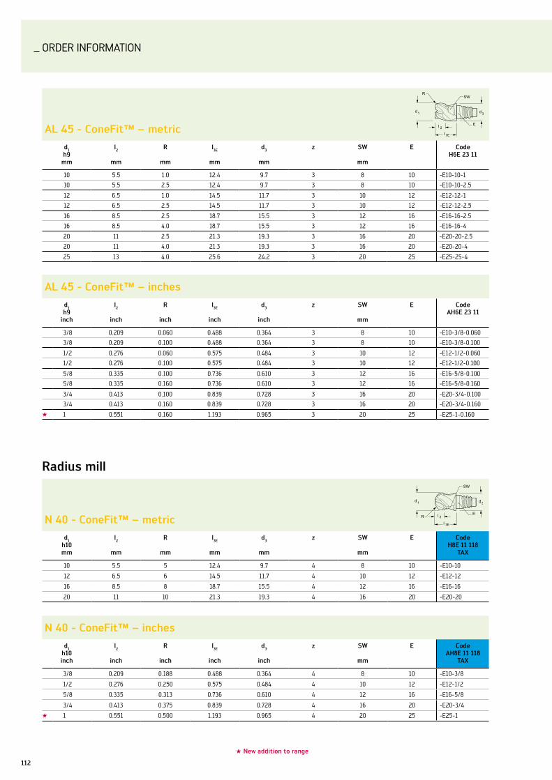
ORDER InFORMATIOn
112
radius mill
n 40 - conefit™ – metricd1
h10mm
l2
mm
r
mm
l3E
mm
d3
mm
z sW
mm
E codeh8E 11 118
Tax
10 5.5 5 12.4 9.7 4 8 10 -E10-10
12 6.5 6 14.5 11.7 4 10 12 -E12-12
16 8.5 8 18.7 15.5 4 12 16 -E16-16
20 11 10 21.3 19.3 4 16 20 -E20-20
al 45 - conefit™ – metricd1h9
mm
l2
mm
r
mm
l3E
mm
d3
mm
z sW
mm
E codeh6E 23 11
10 5.5 1.0 12.4 9.7 3 8 10 -E10-10-1
10 5.5 2.5 12.4 9.7 3 8 10 -E10-10-2.5
12 6.5 1.0 14.5 11.7 3 10 12 -E12-12-1
12 6.5 2.5 14.5 11.7 3 10 12 -E12-12-2.5
16 8.5 2.5 18.7 15.5 3 12 16 -E16-16-2.5
16 8.5 4.0 18.7 15.5 3 12 16 -E16-16-4
20 11 2.5 21.3 19.3 3 16 20 -E20-20-2.5
20 11 4.0 21.3 19.3 3 16 20 -E20-20-4
25 13 4.0 25.6 24.2 3 20 25 -E25-25-4
al 45 - conefit™ – inchesd1h9
inch
l2
inch
r
inch
l3E
inch
d3
inch
z sW
mm
E codeah6E 23 11
3/8 0.209 0.060 0.488 0.364 3 8 10 -E10-3/8-0.060
3/8 0.209 0.100 0.488 0.364 3 8 10 -E10-3/8-0.100
1/2 0.276 0.060 0.575 0.484 3 10 12 -E12-1/2-0.060
1/2 0.276 0.100 0.575 0.484 3 10 12 -E12-1/2-0.100
5/8 0.335 0.100 0.736 0.610 3 12 16 -E16-5/8-0.100
5/8 0.335 0.160 0.736 0.610 3 12 16 -E16-5/8-0.160
3/4 0.413 0.100 0.839 0.728 3 16 20 -E20-3/4-0.100
3/4 0.413 0.160 0.839 0.728 3 16 20 -E20-3/4-0.160
★ 1 0.551 0.160 1.193 0.965 3 20 25 -E25-1-0.160
n 40 - conefit™ – inchesd1
h10inch
l2
inch
r
inch
l3E
inch
d3
inch
z sW
mm
E codeah8E 11 118
Tax
3/8 0.209 0.188 0.488 0.364 4 8 10 -E10-3/8
1/2 0.276 0.250 0.575 0.484 4 10 12 -E12-1/2
5/8 0.335 0.313 0.736 0.610 4 12 16 -E16-5/8
3/4 0.413 0.375 0.839 0.728 4 16 20 -E20-3/4
★ 1 0.551 0.500 1.193 0.965 4 20 25 -E25-1
★ new addition to range

ORDER InFORMATIOn
113Walter Prototyp – Milling
Profiles
chamfer mill 60° - conefit™ – metricd1h9
mm
l2
mm
l3E
mm
d3
mm
d4
mm
z sW
mm
E codeh3E 58 518
Tax
60° 12 6.5 14.5 11.7 1.5 6 10 12 -E12-12
chamfer mill 60° - conefit™ – inchesd1h9
inch
l2
inch
l3E
inch
d3
inch
d4
inch
z sW
mm
E codeah3E 58 518
Tax
60° 1/2 0.280 0.575 0.484 0.177 6 10 12 -E12-1/2
chamfer mill 90° - conefit™ – metricd1h9
mm
l2
mm
l3E
mm
d3
mm
d4
mm
z sW
mm
E codeh3E 58 318
Tax
90° 12 4.5 14.5 11.7 3 6 10 12 -E12-12
90° 16 6.5 18.7 15.5 3 8 12 16 -E16-16
chamfer mill 90° - conefit™ – inchesd1h9
inch
l2
inch
l3E
inch
d3
inch
d4
inch
z sW
mm
E codeah3E 58 318
Tax
90° 1/2 0.191 0.575 0.484 0.118 6 10 12 -E12-1/2
90° 5/8 0.256 0.736 0.610 0.118 8 12 16 -E16-5/8
chamfer mill 120° - conefit™ – metricd1h9
mm
l2
mm
l3E
mm
d3
mm
d4
mm
z sW
mm
E codeh3E 58 118
Tax
120° 12 2.6 14.5 11.7 4.5 6 10 12 -E12-12
chamfer mill 120° - conefit™ – inchesd1h9
inch
l2
inch
l3E
inch
d3
inch
d4
inch
z sW
mm
E codeah3E 58 118
Tax
120° 1/2 0.110 0.575 0.484 0.118 6 10 12 -E12-1/2
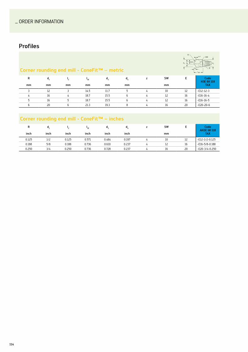
ORDER InFORMATIOn
114
Profiles
corner rounding end mill - conefit™ – metricr
mm
d1
mm
l2
mm
l3E
mm
d3
mm
d4
mm
z sW
mm
E codeh3E 68 118
Tax
3 12 3 14.5 11.7 5 4 10 12 -E12-12-3
4 16 4 18.7 15.5 6 4 12 16 -E16-16-4
5 16 5 18.7 15.5 6 4 12 16 -E16-16-5
6 20 6 21.3 19.3 8 4 16 20 -E20-20-6
corner rounding end mill - conefit™ – inchesr
inch
d1
inch
l2
inch
l3E
inch
d3
inch
d4
inch
z sW
mm
E codeah3E 68 118
Tax
0.125 1/2 0.125 0.571 0.484 0.197 4 10 12 -E12-1/2-0.125
0.188 5/8 0.188 0.736 0.610 0.237 4 12 16 -E16-5/8-0.188
0.250 3/4 0.250 0.736 0.728 0.237 4 16 20 -E20-3/4-0.250

ORDER InFORMATIOn
115Walter Prototyp – Milling
adaptors – steel
E10 - conefit™ – metricE l3h
mm
d3
mm
l1h
mm
d2h6
mm
Type Max. speed rpm
code
10 5 9.6 — 65 16 A 40,000 AK610.Z16.E10.005
10 20 9.6 — 75 10 A 40,000 AK610.Z10.E10.020
10 50 9.6 89° 160 16 B 12,000 AK610.Z16.E10.050
10 36.5 9.6 85° 140 16 C 16,000 AK610.Z16.E10.036
E10 - conefit™ – inchesE l3h
inch
d3
inch
l1h
inch
d2h6
inch
Type Max. speed rpm
code
10 0.236 0.360 — 2.500 0.500 A 40,000 AK610.uZ13.E10.006
10 0.984 0.360 — 3.000 0.500 A 30,000 AK610.uZ13.E10.025
10 2.008 0.360 89° 6.500 0.625 B 12,000 AK610.uZ15.E10.051
10 1.496 0.360 85° 5.500 0.625 C 15,000 AK610.uZ15.E10.038
E12 - conefit™ – metricE l3h
mm
d3
mm
l1h
mm
d2h6
mm
Type Max. speed rpm
code
12 5 11.6 — 65 16 A 40,000 AK610.Z16.E12.005
12 22 11.6 — 100 12 A 31,000 AK610.Z12.E12.022
12 60 11.6 89° 170 16 B 10,000 AK610.Z16.E12.060
12 25.1 11.6 85° 140 16 C 16,000 AK610.Z16.E12.025
E12 - conefit™ – inchesE l3h
inch
d3
inch
l1h
inch
d2h6
inch
Type Max. speed rpm
code
12 0.236 0.480 — 3.000 0.500 A 40,000 AK610.uZ13.E12.006
12 0.984 0.480 — 4.500 0.500 A 30,000 AK610.uZ13.E12.025
12 2.402 0.480 89° 7.500 0.625 B 10,000 AK610.uZ15.E12.061
12 0.827 0.480 85° 6.500 0.625 C 15,000 AK610.uZ15.E12.021
Type a Type b
Type c

ORDER InFORMATIOn
116
adaptors – steel
E16 - conefit™ – metricE l3h
mm
d3
mm
l1h
mm
d2h6
mm
Type Max. speed rpm
code
16 5 15.4 — 70 20 A 40,000 AK610.Z20.E16.005
16 25 15.4 — 110 20 A 31,000 AK610.Z20.E16.025
16 75 15.4 89° 190 20 B 11,000 AK610.Z20.E16.075
16 54.8 15.4 85° 170 25 C 18,000 AK610.Z25.E16.054
E16 - conefit™ – inchesE l3h
inch
d3
inch
l1h
inch
d2h6
inch
Type Max. speed rpm
code
16 0.236 0.606 — 3.000 0.625 A 40,000 AK610.uZ15.E16.006
16 0.984 0.606 — 4.500 0.625 A 30,000 AK610.uZ15.E16.025
16 2.992 0.606 89° 7.500 0.750 B 10,000 AK610.uZ19.E16.076
16 0.827 0.606 85° 6.500 0.750 C 15,000 AK610.uZ19.E16.021
E20 - conefit™ – metricE l3h
mm
d3
mm
l1h
mm
d2h6
mm
Type Max. speed rpm
code
20 5 19.2 — 80 25 A 40,000 AK610.Z25.E20.005
20 30 19.2 — 120 20 A 34,000 AK610.Z20.E20.030
20 73.1 19.2 85° 180 32 C 20,000 AK610.Z32.E20.073
E20 - conefit™ – inchesE l3h
inch
d3
inch
l1h
inch
d2h6
inch
Type Max. speed rpm
code
20 0.236 0.724 — 3.000 0.750 A 20,000 AK610.uZ19.E20.006
20 0.984 0.724 — 4.500 0.750 A 30,000 AK610.uZ19.E20.025
20 1.575 0.724 85° 6.500 1.000 C 20,000 AK610.uZ26.E20.040
E25 - conefit™ – metricE l3h
mm
d3
mm
l1h
mm
d2h6
mm
Type Max. speed rpm
code
25 5 24.1 — 80 32 A 30,000 AK610.Z32.E25.005
25 40 24.1 — 140 25 A 15,000 AK610.Z25.E25.040
25 45 24.1 85° 200 32 C 20,000 AK610.Z32.E25.045
E25 - conefit™ – inchesE l3h
inch
d3
inch
l1h
inch
d2h6
inch
Type Max. speed rpm
code
25 0.236 0.961 — 3.500 1.000 A 30,000 AK610.uZ26.E25.006
25 2.480 0.961 — 6.500 1.250 A 20,000 AK610.uZ31.E25.063
25 0.236 0.961 85° 7.500 1.250 C 15,000 AK610.uZ31.E25.042

ORDER InFORMATIOn
117Walter Prototyp – Milling
adaptors – solid carbide
E10 - conefit™ – metricE l3h
mm
d3
mm
l1h
mm
d2h6
mm
Type Max. speed rpm
code
10 50 9.6 — 100 10 A 20,000 AK610.Z10.E10.050C
10 100 9.6 89° 155 16 B 15,000 AK610.Z16.E10.100C
E10 - conefit™ – inchesE l3h
inch
d3
inch
l1h
inch
d2h6
inch
Type Max. speed rpm
code
10 2.008 0.360 — 4.000 0.500 A 25,000 AK610.uZ13.E10.051C
10 2.008 0.360 89° 6.500 0.625 B 20,000 AK610.uZ15.E10.051C
E12 - conefit™ – metricE l3h
mm
d3
mm
l1h
mm
d2h6
mm
Type Max. speed rpm
code
12 48 11.6 — 100 12 A 30,000 AK610.Z12.E12.048C
12 90 11.6 89° 150 16 B 15,000 AK610.Z16.E12.090C
E12 - conefit™ – inchesE l3h
inch
d3
inch
l1h
inch
d2h6
inch
Type Max. speed rpm
code
12 1.260 0.480 — 4.000 0.500 A 30,000 AK610.uZ13.E12.032C
12 2.402 0.480 89° 7.500 0.625 B 15,000 AK610.uZ15.E12.061C
E16 - conefit™ – metricE l3h
mm
d3
mm
l1h
mm
d2h6
mm
Type Max. speed rpm
code
16 80 15.4 — 135 16 A 30,000 AK610.Z16.E16.080C
16 118 15.4 89° 175 20 B 10,000 AK610.Z20.E16.118C
E16 - conefit™ – inchesE l3h
inch
d3
inch
l1h
inch
d2h6
inch
Type Max. speed rpm
code
16 2.008 0.606 — 5.500 0.750 A 30,000 AK610.uZ19.E16.051C
16 2.992 0.606 89° 7.500 0.750 B 10,000 AK610.uZ19.E16.076C
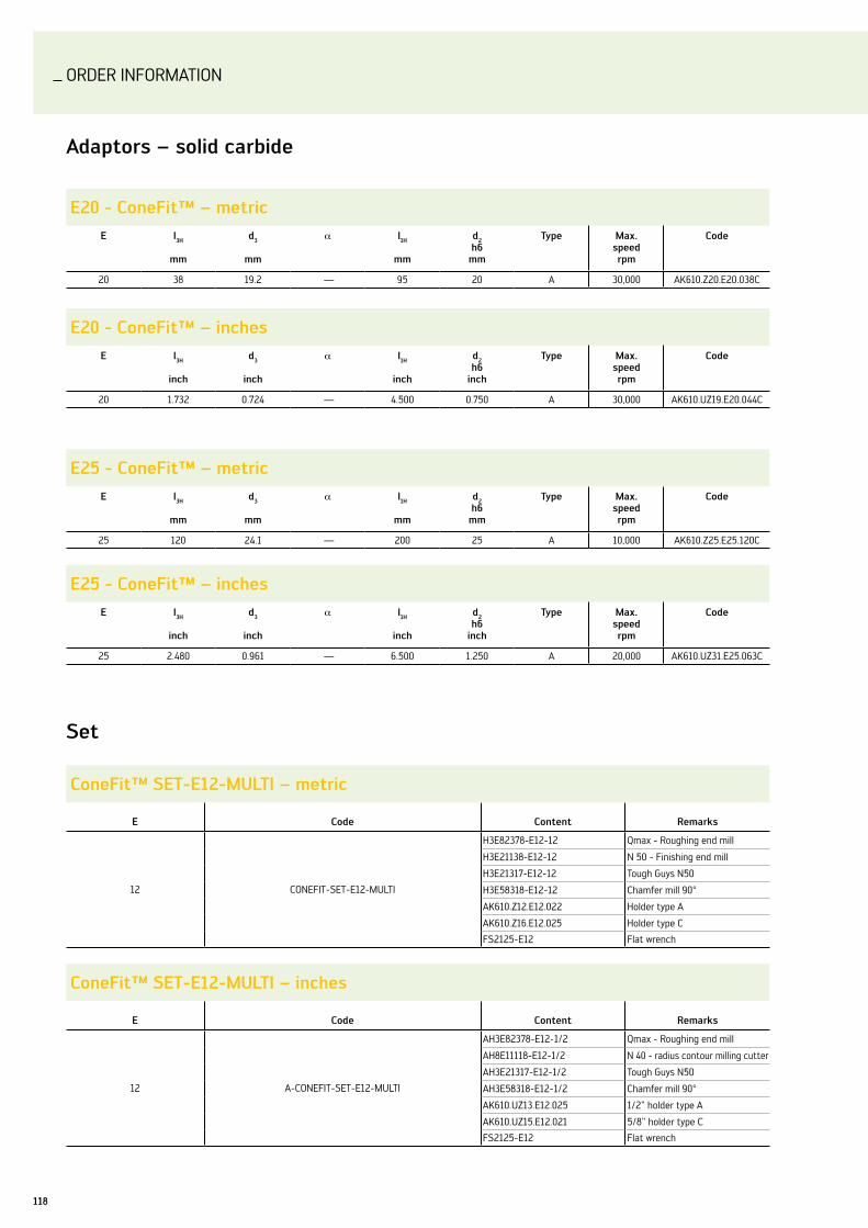
ORDER InFORMATIOn
118
set
conefit™ sET-E12-MulTi – metric
E code content remarks
12 COnEFIT-SET-E12-MulTI
H3E82378-E12-12 Qmax - Roughing end mill
H3E21138-E12-12 n 50 - Finishing end mill
H3E21317-E12-12 Tough Guys n50
H3E58318-E12-12 Chamfer mill 90°
AK610.Z12.E12.022 Holder type A
AK610.Z16.E12.025 Holder type C
FS2125-E12 Flat wrench
conefit™ sET-E12-MulTi – inches
E code content remarks
12 A-COnEFIT-SET-E12-MulTI
AH3E82378-E12-1/2 Qmax - Roughing end mill
AH8E11118-E12-1/2 n 40 - radius contour milling cutter
AH3E21317-E12-1/2 Tough Guys n50
AH3E58318-E12-1/2 Chamfer mill 90°
AK610.uZ13.E12.025 1/2" holder type A
AK610.uZ15.E12.021 5/8" holder type C
FS2125-E12 Flat wrench
adaptors – solid carbide
E20 - conefit™ – metricE l3h
mm
d3
mm
l1h
mm
d2h6
mm
Type Max. speed rpm
code
20 38 19.2 — 95 20 A 30,000 AK610.Z20.E20.038C
E20 - conefit™ – inchesE l3h
inch
d3
inch
l1h
inch
d2h6
inch
Type Max. speed rpm
code
20 1.732 0.724 — 4.500 0.750 A 30,000 AK610.uZ19.E20.044C
E25 - conefit™ – metricE l3h
mm
d3
mm
l1h
mm
d2h6
mm
Type Max. speed rpm
code
25 120 24.1 — 200 25 A 10,000 AK610.Z25.E25.120C
E25 - conefit™ – inchesE l3h
inch
d3
inch
l1h
inch
d2h6
inch
Type Max. speed rpm
code
25 2.480 0.961 — 6.500 1.250 A 20,000 AK610.uZ31.E25.063C

ORDER InFORMATIOn
119Walter Prototyp – Milling
Wrenches
flat wrench - conefit™
E sW Type code
10 8 Twin head FS2124-E10
12 10 Twin head FS2125-E12
16 12 Twin head FS2126-E16
20 16 Single head FS2127-E20
25 20 Single head FS2128-E25
Torque wrench - conefit™
D Torque range code
16 2-25 nm FS1384
16 10-100 nm FS1385
keys for torque wrench - conefit™
E sW D nm code
10 8 16 12 FS2135-E10-R
12 10 16 15 FS2136-E12-R
16 12 16 30 FS2137-E16-R
20 16 16 50 FS2138-E20-R
25 20 16 65 FS2141-E25-R

ORDER InFORMATIOn
120
sky·tec™ al 25 – metric
P norm xld1
h10mm
l2
mm
r
mm
l3 d3 l1
mm
lk
mm
d2h5mm
z codeh 60 2691
12 12 0.5 68 11.5 115 70 12 2 -12-12-0.5
12 12 2 68 11.5 115 70 12 2 -12-12-2
16 16 0.5 80 15.2 130 83 16 2 -16-16-0.5
16 16 2 80 15.2 130 82 16 2 -16-16-2
16 16 3 80 15.2 130 82 16 2 -16-16-3
20 20 0.5 88 19 140 90 20 2 -20-20-0.5
20 20 2 88 19 140 90 20 2 -20-20-2
20 20 3 88 19 140 90 20 2 -20-20-3
20 20 4 88 19 140 90 20 2 -20-20-4
25 25 0.5 92 23.75 150 94 25 2 -25-25-0.5
25 25 2 92 23.75 150 94 25 2 -25-25-2
25 25 3 92 23.75 150 94 25 2 -25-25-3
25 25 4 92 23.75 150 94 25 2 -25-25-4
sky·tec™ al 25 – inches
Extra longd1
h10mm
l2
mm
r
mm
l3 d3 l1
mm
lk
mm
d2h5mm
z codeah 60 2691
1/2 0.500 0.030 2.638 0.469 4.500 2.717 0.500 2 -1/2-0.500-0.030
1/2 0.500 0.060 2.638 0.469 4.500 2.717 0.500 2 -1/2-0.500-0.060
1/2 0.500 0.125 2.638 0.469 4.500 2.717 0.500 2 -1/2-0.500-0.125
1/2 0.500 0.187 2.638 0.469 4.500 2.717 0.500 2 -1/2-0.500-0.187
5/8 0.625 0.030 2.953 0.598 5.000 3.031 0.625 2 -5/8-0.625-0.030
5/8 0.625 0.060 2.953 0.598 5.000 3.031 0.625 2 -5/8-0.625-0.060
5/8 0.625 0.125 2.953 0.598 5.000 3.031 0.625 2 -5/8-0.625-0.125
3/4 0.750 0.030 3.386 0.717 5.500 3.465 0.750 2 -3/4-0.750-0.030
3/4 0.750 0.060 3.386 0.717 5.500 3.465 0.750 2 -3/4-0.750-0.060
3/4 0.750 0.125 3.386 0.717 5.500 3.465 0.750 2 -3/4-0.750-0.125
3/4 0.750 0.187 3.386 0.717 5.500 3.465 0.750 2 -3/4-0.750-0.187
1 1.000 0.030 3.638 0.961 6.000 3.717 1.000 2 -1-1.000-0.030
1 1.000 0.060 3.638 0.961 6.000 3.717 1.000 2 -1-1.000-0.060
1 1.000 0.125 3.638 0.961 6.000 3.717 1.000 2 -1-1.000-0.125
1 1.000 0.187 3.638 0.961 6.000 3.717 1.000 2 -1-1.000-0.187
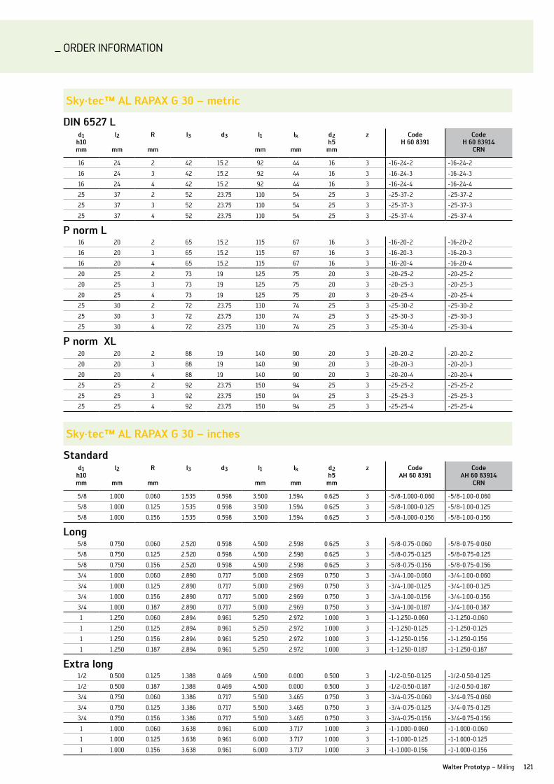
ORDER InFORMATIOn
121Walter Prototyp – Milling
sky·tec™ al raPax g 30 – metric
Din 6527 ld1
h10mm
l2
mm
r
mm
l3 d3 l1
mm
lk
mm
d2h5mm
z codeh 60 8391
codeh 60 83914
crn
16 24 2 42 15.2 92 44 16 3 -16-24-2 -16-24-2
16 24 3 42 15.2 92 44 16 3 -16-24-3 -16-24-3
16 24 4 42 15.2 92 44 16 3 -16-24-4 -16-24-4
25 37 2 52 23.75 110 54 25 3 -25-37-2 -25-37-2
25 37 3 52 23.75 110 54 25 3 -25-37-3 -25-37-3
25 37 4 52 23.75 110 54 25 3 -25-37-4 -25-37-4
P norm l16 20 2 65 15.2 115 67 16 3 -16-20-2 -16-20-2
16 20 3 65 15.2 115 67 16 3 -16-20-3 -16-20-3
16 20 4 65 15.2 115 67 16 3 -16-20-4 -16-20-4
20 25 2 73 19 125 75 20 3 -20-25-2 -20-25-2
20 25 3 73 19 125 75 20 3 -20-25-3 -20-25-3
20 25 4 73 19 125 75 20 3 -20-25-4 -20-25-4
25 30 2 72 23.75 130 74 25 3 -25-30-2 -25-30-2
25 30 3 72 23.75 130 74 25 3 -25-30-3 -25-30-3
25 30 4 72 23.75 130 74 25 3 -25-30-4 -25-30-4
P norm xl20 20 2 88 19 140 90 20 3 -20-20-2 -20-20-2
20 20 3 88 19 140 90 20 3 -20-20-3 -20-20-3
20 20 4 88 19 140 90 20 3 -20-20-4 -20-20-4
25 25 2 92 23.75 150 94 25 3 -25-25-2 -25-25-2
25 25 3 92 23.75 150 94 25 3 -25-25-3 -25-25-3
25 25 4 92 23.75 150 94 25 3 -25-25-4 -25-25-4
sky·tec™ al raPax g 30 – inches
standardd1
h10mm
l2
mm
r
mm
l3 d3 l1
mm
lk
mm
d2h5mm
z codeah 60 8391
codeah 60 83914
crn
5/8 1.000 0.060 1.535 0.598 3.500 1.594 0.625 3 -5/8-1.000-0.060 -5/8-1.00-0.060
5/8 1.000 0.125 1.535 0.598 3.500 1.594 0.625 3 -5/8-1.000-0.125 -5/8-1.00-0.125
5/8 1.000 0.156 1.535 0.598 3.500 1.594 0.625 3 -5/8-1.000-0.156 -5/8-1.00-0.156
long 5/8 0.750 0.060 2.520 0.598 4.500 2.598 0.625 3 -5/8-0.75-0.060 -5/8-0.75-0.060
5/8 0.750 0.125 2.520 0.598 4.500 2.598 0.625 3 -5/8-0.75-0.125 -5/8-0.75-0.125
5/8 0.750 0.156 2.520 0.598 4.500 2.598 0.625 3 -5/8-0.75-0.156 -5/8-0.75-0.156
3/4 1.000 0.060 2.890 0.717 5.000 2.969 0.750 3 -3/4-1.00-0.060 -3/4-1.00-0.060
3/4 1.000 0.125 2.890 0.717 5.000 2.969 0.750 3 -3/4-1.00-0.125 -3/4-1.00-0.125
3/4 1.000 0.156 2.890 0.717 5.000 2.969 0.750 3 -3/4-1.00-0.156 -3/4-1.00-0.156
3/4 1.000 0.187 2.890 0.717 5.000 2.969 0.750 3 -3/4-1.00-0.187 -3/4-1.00-0.187
1 1.250 0.060 2.894 0.961 5.250 2.972 1.000 3 -1-1.250-0.060 -1-1.250-0.060
1 1.250 0.125 2.894 0.961 5.250 2.972 1.000 3 -1-1.250-0.125 -1-1.250-0.125
1 1.250 0.156 2.894 0.961 5.250 2.972 1.000 3 -1-1.250-0.156 -1-1.250-0.156
1 1.250 0.187 2.894 0.961 5.250 2.972 1.000 3 -1-1.250-0.187 -1-1.250-0.187
Extra long 1/2 0.500 0.125 1.388 0.469 4.500 0.000 0.500 3 -1/2-0.50-0.125 -1/2-0.50-0.125
1/2 0.500 0.187 1.388 0.469 4.500 0.000 0.500 3 -1/2-0.50-0.187 -1/2-0.50-0.187
3/4 0.750 0.060 3.386 0.717 5.500 3.465 0.750 3 -3/4-0.75-0.060 -3/4-0.75-0.060
3/4 0.750 0.125 3.386 0.717 5.500 3.465 0.750 3 -3/4-0.75-0.125 -3/4-0.75-0.125
3/4 0.750 0.156 3.386 0.717 5.500 3.465 0.750 3 -3/4-0.75-0.156 -3/4-0.75-0.156
1 1.000 0.060 3.638 0.961 6.000 3.717 1.000 3 -1-1.000-0.060 -1-1.000-0.060
1 1.000 0.125 3.638 0.961 6.000 3.717 1.000 3 -1-1.000-0.125 -1-1.000-0.125
1 1.000 0.156 3.638 0.961 6.000 3.717 1.000 3 -1-1.000-0.156 -1-1.000-0.156
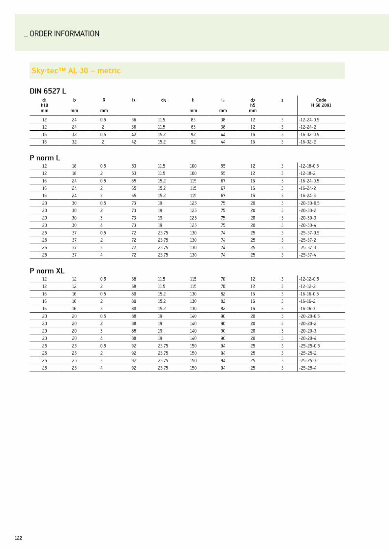
ORDER InFORMATIOn
122
sky·tec™ al 30 – metric
Din 6527 ld1
h10mm
l2
mm
r
mm
l3 d3 l1
mm
lk
mm
d2h5mm
z codeh 60 2091
12 24 0.5 36 11.5 83 38 12 3 -12-24-0.5
12 24 2 36 11.5 83 38 12 3 -12-24-2
16 32 0.5 42 15.2 92 44 16 3 -16-32-0.5
16 32 2 42 15.2 92 44 16 3 -16-32-2
P norm l12 18 0.5 53 11.5 100 55 12 3 -12-18-0.5
12 18 2 53 11.5 100 55 12 3 -12-18-2
16 24 0.5 65 15.2 115 67 16 3 -16-24-0.5
16 24 2 65 15.2 115 67 16 3 -16-24-2
16 24 3 65 15.2 115 67 16 3 -16-24-3
20 30 0.5 73 19 125 75 20 3 -20-30-0.5
20 30 2 73 19 125 75 20 3 -20-30-2
20 30 3 73 19 125 75 20 3 -20-30-3
20 30 4 73 19 125 75 20 3 -20-30-4
25 37 0.5 72 23.75 130 74 25 3 -25-37-0.5
25 37 2 72 23.75 130 74 25 3 -25-37-2
25 37 3 72 23.75 130 74 25 3 -25-37-3
25 37 4 72 23.75 130 74 25 3 -25-37-4
P norm xl12 12 0.5 68 11.5 115 70 12 3 -12-12-0.5
12 12 2 68 11.5 115 70 12 3 -12-12-2
16 16 0.5 80 15.2 130 82 16 3 -16-16-0.5
16 16 2 80 15.2 130 82 16 3 -16-16-2
16 16 3 80 15.2 130 82 16 3 -16-16-3
20 20 0.5 88 19 140 90 20 3 -20-20-0.5
20 20 2 88 19 140 90 20 3 -20-20-2
20 20 3 88 19 140 90 20 3 -20-20-3
20 20 4 88 19 140 90 20 3 -20-20-4
25 25 0.5 92 23.75 150 94 25 3 -25-25-0.5
25 25 2 92 23.75 150 94 25 3 -25-25-2
25 25 3 92 23.75 150 94 25 3 -25-25-3
25 25 4 92 23.75 150 94 25 3 -25-25-4

ORDER InFORMATIOn
123Walter Prototyp – Milling
sky·tec™ al 30 – inches
standardd1
h10mm
l2
mm
r
mm
l3 d3 l1
mm
lk
mm
d2h5mm
zcode
ah 60 2091
1/2 1.000 0.030 1.388 0.469 3.250 1.467 0.500 3 -1/2-1.000-0.030
1/2 1.000 0.060 1.388 0.469 3.250 1.467 0.500 3 -1/2-1.000-0.060
long 1/2 0.750 0.030 2.138 0.469 4.000 2.217 0.500 3 -1/2-0.750-0.030
1/2 0.750 0.060 2.138 0.469 4.000 2.217 0.500 3 -1/2-0.750-0.060
5/8 1.000 0.030 2.520 0.598 4.500 2.598 0.625 3 -5/8-1.000-0.030
5/8 1.000 0.060 2.520 0.598 4.500 2.598 0.625 3 -5/8-1.000-0.060
5/8 1.000 0.125 2.520 0.598 4.500 2.598 0.625 3 -5/8-1.000-0.125
3/4 1.125 0.030 2.890 0.717 5.000 2.969 0.750 3 -3/4-1.125-0.030
3/4 1.125 0.060 2.890 0.717 5.000 2.969 0.750 3 -3/4-1.125-0.060
3/4 1.125 0.125 2.890 0.717 5.000 2.969 0.750 3 -3/4-1.125-0.125
3/4 1.125 0.187 2.890 0.717 5.000 2.969 0.750 3 -3/4-1.125-0.187
1 1.500 0.030 2.894 0.961 5.250 2.972 1.000 3 -1-1.500-0.030
1 1.500 0.060 2.894 0.961 5.250 2.972 1.000 3 -1-1.500-0.060
1 1.500 0.125 2.894 0.961 5.250 2.972 1.000 3 -1-1.500-0.125
1 1.500 0.187 2.894 0.961 5.250 2.972 1.000 3 -1-1.500-0.187
Extra long 1/2 0.500 0.030 2.638 0.469 4.500 2.717 0.500 3 -1/2-0.500-0.030
1/2 0.500 0.060 2.638 0.469 4.500 2.717 0.500 3 -1/2-0.500-0.060
1/2 0.500 0.125 2.638 0.469 4.500 2.717 0.500 3 -1/2-0.500-0.125
1/2 0.500 0.187 2.638 0.469 4.500 2.717 0.500 3 -1/2-0.500-0.187
5/8 0.625 0.030 2.953 0.598 5.000 3.031 0.625 3 -5/8-0.625-0.030
5/8 0.625 0.060 2.953 0.598 5.000 3.031 0.625 3 -5/8-0.625-0.060
5/8 0.625 0.125 2.953 0.598 5.000 3.031 0.625 3 -5/8-0.625-0.125
3/4 0.750 0.030 3.386 0.717 5.500 3.465 0.750 3 -3/4-0.750-0.030
3/4 0.750 0.060 3.386 0.717 5.500 3.465 0.750 3 -3/4-0.750-0.060
3/4 0.750 0.125 3.386 0.717 5.500 3.465 0.750 3 -3/4-0.750-0.125
1 1.000 0.030 3.638 0.961 6.000 3.717 1.000 3 -1-1.000-0.030
1 1.000 0.060 3.638 0.961 6.000 3.717 1.000 3 -1-1.000-0.060
1 1.000 0.125 3.638 0.961 6.000 3.717 1.000 3 -1-1.000-0.125
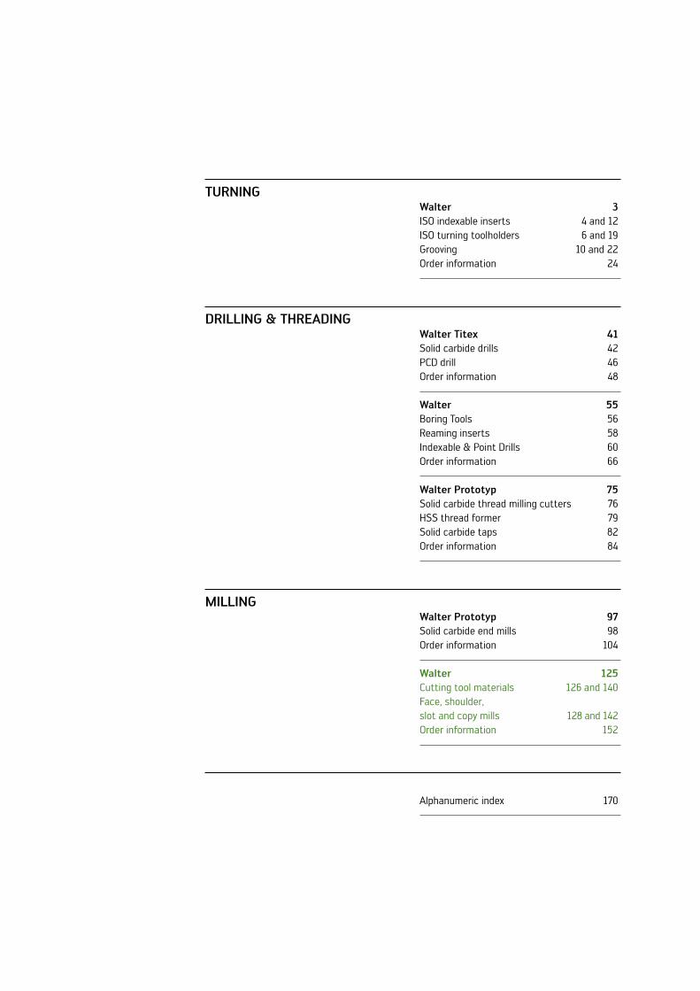
Turning
Drilling & ThrEaDing
Milling
Walter 3ISO indexable inserts 4 and 12ISO turning toolholders 6 and 19Grooving 10 and 22Order information 24
Walter Titex 41Solid carbide drills 42PCD drill 46Order information 48
Walter 55Boring Tools 56Reaming inserts 58Indexable & Point Drills 60Order information 66
Walter Prototyp 75Solid carbide thread milling cutters 76HSS thread former 79Solid carbide taps 82Order information 84
Walter Prototyp 97Solid carbide end mills 98Order information 104
Walter 125Cutting tool materials 126 and 140Face, shoulder, slot and copy mills 128 and 142Order information 152
Alphanumeric index 170

_TOOl InnOvATIOnS In MIllInG
high machining volume with xtra·tec® milling cutters.
Product innovations Edition 2010-1
Milling

126
CuTTInG TOOl MATERIAlS
Walter Tiger·tec®silver – the new force in machining.
ThE TEchnology – uniquE WorlDWiDE
Thanks to its new, thoroughly unique CvD coating technology, Tiger·tec®silver is forging ahead into completely new dimensions with increases in output of up to 100 %. The decisive benefits of the new technology are:
Enormous toughness and minimal formation –of hairline cracks thanks to optimum residual strengthGreatly reduced tribochemical wear thanks to –perfect, smooth rake facesnot susceptible to thermal stress variations during –wet and dry machining
ThE cuTTing Tool MaTErial: PErforMancE WiThouT liMiTs
With Tiger·tec® cutting tool materials, we have been setting new standards in machining for many years. The new Tiger·tec®silver cutting tool material is another giant step on the way to the perfect cutting tool material. It is ideal for dry and wet machining in automotive engineering and railway vehicle manufac-turing, in power engineering, toolmaking and mould and die construction, aerospace engineering and in general mechanical engineering.
NEW2010
TigEr·TEc®silvEr TEchnology
Completely new CvD technology:combines wear resistance and –toughnessfor cast iron and steel materials –
Optimum friction behaviour
Resistant to tribochemical wear
Greater resistance to flank face wear
Excellent hardness to toughness ratio
-Al2O3
Ti(C,n)
Substrate
Tiger·tec®silver Type: ODHT0605…
The following indexable inserts are available in the Tiger·tec®silver cutting material WKP35S:
OD…0504… for F4080 –OD…0605… for F4080 –AD…0803… for F4042 –AD…10T3… for F4042R –AD…1204… for F4042 –AD…1606… for F4042 –AD…1807… for F4042 –XnHF0705… for F4045 –XnHF0906… for F4045 –
P23696-1 for F4030 –ln.X0702 for F4053 –ln.u… for F4153 –ln.u… for F4253 –Sn.X1205 for F4033 –Sn.X1205 for F4047 –Sn.X1205 for F4048 –Sn.X1606 for F4033 –lnGX1307 for F4041 –

127Walter – Milling
coMPETiTors
Competitor products exhibit heavy, clearly visible wear on the cutting edge and significant chipping.
Tiger·tec®Silver
The high level of wear resistance, toughness and temperature resistance prevents the formation of hairline cracks and chipping. The insert lasts longer.
Tiger·tec®
Relatively even signs of wear and a low formation of hairline cracks demonstrate the performance of the legendary Tiger·tec® cutting tool materials.
Average increase in output of 75 % in milling
cast iron and steel
Extremely stable cutting edges for
high level of process reliability
Extremely smooth rake face for excellent tribochemical
wear resistance
Silver coloured flank face for very easy wear detection
during use
Tool lifE coMParison: blade machining
cutting data
vc 310 m/minfz 0.4 mmap 3 mmae 25 mm
competitor
Tiger·tec®
Tiger·tec®Silver
0 10 20 30 40 Tool life minutes
Up to +100 %
Workpiece material: X22CrMov12-1cutting tool material: WKP35Scoolant: no

128
FACE MIllInG
Walter xtra·tec® high Performance mill f4030 – fast-feed milling with 6-edge indexable insert.
ThE Tool
Surface milling, plunge milling and copy – milling cutter with double sided Trigon indexable insertslead angle 0 - 15° –Ø 25 – 63 mm –Cutting depth 1 mm –up to 3.5 mm feed per tooth –
ThE inDExablE insErTs
6 cutting edges per indexable insert due to –negative basic shape Tiger·tec – ®Silver cutting tool material WKP35S for highest possible cutting data and tool lifeCombination of easy-cutting geometry and –high stability
aPPlicaTions
For machining steel, stainless steel, cast –iron and difficult to machine materialsFor fast-feed face milling, inclined plunging, –circular interpolation milling and plungingCan be used in practically any sector, e.g. –energy industry or mould and die making
Hard-nickel plated body
Tiger·tec®silver
lead angle 0 - 15°
xtra·tec® surface milling range Type: F4030
your aDvanTagEs
High machining volume thanks to the –combination of low cutting depths and high tooth feedsHigh level of process reliability thanks –to low vibration risk of long tools and stable insertReduced process costs with –Tiger·tec®Silver cutting tool material and 6 cutting edges per indexable insert
NEW2010

129Walter – Milling
ThE inDExablE insErT
P23696-1.0 – the universal oneFor medium to unfavourable – machining conditionslow cutting forces –16° rake angle –Can be used in practically any – sector, e.g. energy industry or mould and die making
Pocket milling form insert
Workpiece material:
40CrMnMoS86(1.2312), ISO P
Tool: F4030 / Z 6 / Ø 63 mmindexable insert: P23696-1.0cutting tool material:
WSP45
cutting data
current WSP45vc 155 m/min 120 m/minfz 1.6 mm 2.0 mmvf 5,980 mm/min 7,275 mm/minap 1 mm 1 mmae 66 mm 63 mmae 30 - 100 mm
Machining time comparison [min]
0 30 60 12090 150
Current 129.5 min
-18 %
F4030 106 min
Machining time [min]
Face milling (roughing)
Pocket milling
Plunging
Inclined plunging
Circular interpolation milling

130
FACE MIllInG
Walter xtra·tec® heptagon cutter f4045 – maximum cost efficiency thanks to 14-edge indexable inserts.
ThE Tools
Face milling cutter, 45° with 14-edge indexable inserts –Cutting depth 4 or 6 mm –Stable and reliable indexable insert clamping by clamping –wedgeStandard range from Ø 63 – 200 mm –Hard-nickel plated surface provides protection from – corrosion and wear, and ensures better chip flow
ThE inDExablE insErTs
14 cutting edges per indexable insert due to negative –basic shapeSoft cutting action thanks to positive cutting edge –Indexable inserts with fully ground circumference, –with secondary cutting edge XnHF0705Ann… or XnHF0906Ann… or with corner radius XnHF070508… or XnHF090612…Tiger·tec – ®silver cutting tool materials for maximum tool life (for details see page 126)
aPPlicaTions
For all cast iron materials, e.g. GG26Cr, GGv, … –For surface milling (roughing) –Ideally suited to the automotive industry and –general mechanical engineering
your aDvanTagEs
High machining volume, even from low-performance –machines, thanks to positive, soft cutting actionHigh level of process reliability thanks to stable, negative –indexable insertslow cutting material costs thanks to 14-edge indexable –insertsMaximum productivity from the universal use of –Tiger·tec® and Tiger·tec®silver coatings
xtra·tec® surface milling range Type: F 4045
14 cutting edges
Compound screw with TorxPlus
Stable indexable insert clamping by clamping wedge
Multi-tooth design
Positive geometry

D27
D67
D57
131Walter – Milling
gEoMETry varianTs
D27 – the stable one:
for unfavourable – machining conditionsmaximum cutting edge –stabilityhigh feed rates –10° rake angle –
D57 – the universal one:
for medium machining –conditionsuniversal application –10° rake angle –
D67 – the easy-cutting one:
for good machining – conditionslow cutting forces –medium feed rates –10° rake angle –
insErT claMPing
Stable and precise clamp- –ing by clamping wedgeMaximum process reliabil- –ity thanks to stable insert designGood accessibility during –indexable insert replace-ment thanks to swivelling wedge Wedge in clamped position
Wedge swivelled
crankcase:rough machining of the oil sump joint face
Workpiece material: GG26Cr, ISO KTool: F 4045 / Z 28 / Ø 200 mmindexable insert: XnHF0705Ann–D27cutting tool material: WKP 25
cutting data
no. of teeth 28vc 120 m/minfz 0.26 mmvf 1,390 mm/minap 4 mmae 30–100 mm
Tool life [components]
0 700 1,400 2,8002,100 3,500
Competitor 2,200
+36 %
F4045 3,000
Components

132
FACE MIllInG
Walter xtra·tec® octagon cutter f4081 – the circular interpolation milling specialist.
ThE Tools
Octagon cutter with 8-edge indexable insert –Extremely soft cutting action thanks to double positive –geometryBalanced construction to ensure improved running –on the spindleØ 36 – 85 mm –Oversize version available –Ø 80 - 315 mm (as cartridge tool F2010 with cartridge –FR681M)lead angle 45° –Two indexable insert sizes for optimum fit to cutting depth –(3 mm and 4 mm)Hard-nickel plated surface provides protection from – corrosion and wear, and ensures better chip flowCircular interpolation milling produces smooth walled –bores – no secondary boring necessary, precision boring possible directly afterwards
your aDvanTagEs
High machining volume, even from low-performance –machines, thanks to positive, soft cutting actionReductions in inventory costs: ideal adaptation of the –tool to various materials thanks to the variety of geom-etries and cutting material gradeslittle or no secondary machining thanks to smooth –walled bores produced by circular interpolation millingHigh level of process reliability and efficiency thanks to –Tiger·tec® cutting tool materialsReduction in tooling costs: a wide range of hole – diameters can be machined using the one mill
8 cutting edges
Double positive geometry
Balanced construction
Two indexable insert sizes available
xtra·tec® surface milling range Type: F4081
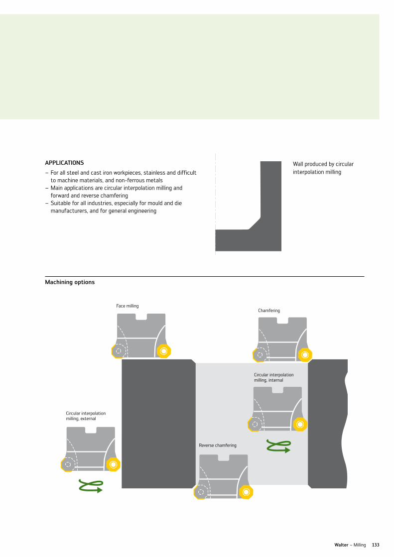
133Walter – Milling
Face millingChamfering
aPPlicaTions
For all steel and cast iron workpieces, stainless and difficult –to machine materials, and non-ferrous metalsMain applications are circular interpolation milling and – forward and reverse chamferingSuitable for all industries, especially for mould and die – manufacturers, and for general engineering
Circular interpolation milling, external
Circular interpolation milling, internal
Reverse chamfering
Machining options
Wall produced by circular interpolation milling
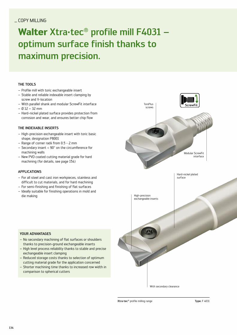
134
COPY MIllInG
Walter xtra·tec® profile mill f4031 – optimum surface finish thanks to maximum precision.
ThE Tools
Profile mill with toric exchangeable insert –Stable and reliable indexable insert clamping by –screw and v-locationWith parallel shank and modular ScrewFit interface –Ø 12 – 32 mm –Hard-nickel plated surface provides protection from –corrosion and wear, and ensures better chip flow
ThE inDExablE insErTs
High-precision exchangeable insert with toric basic –shape, designation P8001Range of corner radii from 0.5 - 2 mm –Secondary insert < 90° on the circumference for –machining wallsnew PvD coated cutting material grade for hard –machining (for details, see page 154)
aPPlicaTions
For all steel and cast iron workpieces, stainless and –difficult to cut materials, and for hard machiningFor semi-finishing and finishing of flat surfaces –Ideally suitable for finishing operations in mold and –die making
your aDvanTagEs
no secondary machining of flat surfaces or shoulders –thanks to precision-ground exchangeable insertsHigh level process reliability thanks to stable and precise –exchangeable insert clampingReduced storage costs thanks to selection of optimum –cutting material grade for the application concernedShorter machining time thanks to increased row width in –comparison to spherical cutters
xtra·tec® profile milling range Type: F 4031
High-precision exchangeable inserts
With secondary clearance
Hard-nickel plated surface
TorxPlus screws
Modular ScrewFit interface

135Walter – Milling
insErT claMPing
High radial and axial runout accuracy thanks to optimum centring of the exchangeable insert by v-location
Elastic deformation of the insert screw by eccentrically positioned screw head counter-sink
Exchangeable insert retained in a v-location by way of the eccentric clamping screw
Test workpiece:finishing in rows
Workpiece material: 40CrMnMo7 (1.2311), ISO PTool: F4031 / Z 2 / Ø 16 / R1.0 mmindexable insert: P8001–D16R10–A57cutting tool material: WHH15
cutting data
no. of teeth 2vc 250 m/minfz 0.1 mmvf 99.5 mm/minap 1 mmae 10 mm
comparison of surface finish achieved in ra [µm]
0 0.4 0.8 1.61.2 2.0
Competitor B
Competitor A
F4031
Ra [µm]
Ra = 0.44 µm
Ra = 0.68 µm
Ra = 1.91 µm

136
SHOulDER MIllInG
Walter xtra·tec® porcupine cutter f4338 – optimum stability for optimum process reliability.
ThE Tools
Porcupine cutter with indexable inserts Ø 63 - 125 mm –Suitable for difficult to cut materials –a – pmax = 28 - 95 mmIndexable insert size AD . T 1807… –Extremely soft-cutting geometry thanks to positive – indexable insert geometry and helical arrangement of the indexable insertslarge variety of different diameters and cutting lengths –Hard-nickel plated surface provides protection from – corrosion and wear, and ensures better chip flowWith other insert sizes from a diameter of 20 mm –
aPPlicaTions
For all steel and cast iron materials, as well as for stainless –steels and difficult to cut materialsFor shoulder milling and trimming –For applications in general mechanical engineering, the – aerospace sector as well as in the energy industry
your aDvanTagEs
High machining volume, even from low-performance –machines, thanks to positive, soft cutting actionReduction in machining costs thanks to almost shoulder- –free millingHigh level of process reliability thanks to axial fixed stop –of the first row of indexable inserts and excellent index-able insert stabilityMaximum productivity from the universal use of –Tiger·tec® coatings
xtra·tec® porcupine cutting range Type: F 4338
System indexable inserts AD...
Axial fixed stop
Hard-nickel plated surface

f56
D56
D51
137Walter – Milling
ThE inDExablE insErTs
System indexable inserts, positive with two cutting edges –Wide selection: –•fullysintered(ADMT…) •fullygroundcircumference(ADGT…)Tiger·tec – ® cutting tool materials for extremely high cutting speedsMaximum process reliability thanks to stable design –
gEoMETry varianTs
D51 – the quiet one:
antivibration geometry –for tools with longer – projection lengths10° rake angle –
D56 – the stable one:
for unfavourable – machining conditionsmaximum cutting edge –stabilityhigh feed rates –10° rake angle –
f56 – the universal one:
for medium machining –conditionsuniversal application for –most materials16° rake angle –
fork lift frame:roughing of master profile
Workpiece material: St52-3 (1.0570), ISO PTool: F4338 / Z 4 / Ø 63 indexable insert: ADMT 180712R–D56cutting tool material: WKP35
cutting data
Walter Currentno. of teeth 4 4vc 197 m/min 160fz 0.18 mm 0.15 mmvf 717 mm/min 485 mm/minap 30 mm 30 mmae 25 mm 25 mm
Machining time per component in seconds
0 8 16 3224 40
Current 37"
–33 %
F4338 25''
Seconds

D67
g77
138
SHOulDER MIllInG AnD COPY MIllInG
new geometries for difficult to machine materials – maximum process reliability with high cutting rates.
ThE gEoMETriEs
Precision-ground indexable inserts in basic shapes AD . . –and RO . .Two special geometries and three cutting material grades –ensure coverage of the entire ISO-S application field (difficult to machine materials)D67 geometry for high tensile steel materials and nickel- –based alloysGeometry G77 for titanium alloys –
aPPlicaTions
Particularly suitable for difficult to cut materials, e.g. – titanium, InconelFor slot milling, shoulder milling and copy milling –For applications in the aerospace sector and energy industry –
your aDvanTagEs
High machining volume, even from low-performance – machines, thanks to positive, soft cutting actionHigh level of process reliability thanks to special – geometries for any field of applicationlong tool life thanks to precise cutting edge design –and high tool concentricity
Type: ROHX . . 08 / 10 / 12 / 16 / –D67
gEoMETry varianTs
D67 – the powerful one:
high cutting edge stability –for machining high-alloy –and high-tensile steels and ni-based alloys, e.g. Inconelhigh level of accuracy –10° rake angle –
g77 – the special one:
for machining titanium –materialslow cutting forces –high level of accuracy –20° rake angle –
Type: aDgT . . 10 / 12 / 16 / –g77
Ideal combination of toughness and hot hardness thanks to PvD Al2O3 coating
Ideal combination of toughness and hot hardness thanks to PvD Al2O3 coating
Special geometry for machining titanium
High cutting edge stability
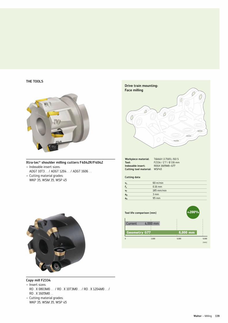
139Walter – Milling
ThE Tools
xtra·tec® shoulder milling cutters f4042r/f4042Indexable insert sizes: –ADGT 10T3 . . / ADGT 1204 . . / ADGT 1606 . .Cutting material grades: –WKP 35, WSM 35, WSP 45
copy mill f2334Insert sizes: –RO . X 0803M0 . . / RO . X 10T3M0 . . / RO . X 1204M0 . . / RO . X 1605M0 . .Cutting material grades: –WKP 35, WSM 35, WSP 45
Drive train mounting:face milling
Workpiece material: Ti6Al4v (3.7165), ISO STool: F2334 / Z 7 / Ø 116 mmindexable insert: ROGX 1605M0–G77cutting tool material: WSP45
cutting data
vc 60 m/minfz 0.16 mmvf 185 mm/minap 3 mmae 95 mm
Tool life comparison [mm]
0 3,000 6,000 9,000
Current 4,000 mm
+200%
geometry g77 8,000 mm
[mm]

140
CuTTInG TOOl MATERIAlS
Walter Tiger·tec® milling cutting material grade Wkk25 – maximum process reliability for cast iron machining.
ThE coaTing
PvD aluminium oxide – Tiger·tec® coating Extreme hardness and temperature resistance combined –with excellent toughnessTiger·tec – ® provides the best process reliability
ThE cuTTing MaTErial graDE
Designation WKK25 –Main application is cast iron materials (ISO K) –Application range HC-K25 –
ThE inDExablE insErTs
For all popular cast iron machining tools from the – xtra·tec® milling range, e.g. •faceandshouldermillingcutters •sideandfacemills •porcupinecutters
aPPlicaTions
For the machining of all cast iron materials, e.g. GG26Cr, –GGv, GGG, …Difficult conditions, e.g. inclusions of sand, or casting skin –For heavily interrupted cuts –
your aDvanTagEs
Maximum process reliability thanks to unique –combination of wear resistance and toughnessBest wear detection from two-tone – Tiger·tec® coating
cross-section through our new PvD al2o3 coated milling cutting material grade Wkk25
rotor hub:roughing of mating faces
Workpiece material: GGG40 (0.7040) ISO K
Tool: F4080 /Z 9 Ø 190 mm
indexable insert: ODMW 060508T–A27
cutting tool material:
WKK25
cutting data
Walter Currentno. of teeth 9 9vc 160 m/min 160 m/minfz 0.44 mm 0.35 mmvf 1,260 mm/min 1,000 mm/minap 4 mm 4 mmae 120 mm 120 mm
comparison of machined volume +26%
0250 500 750
Current Q = 480 cm3/min
WKK25 Q = 605 cm3/min
[cm3/min]

141
CuTTInG TOOl MATERIAlS
Walter milling cutting material grade Whh 15 – maximum wear resistance for long tool life during hard machining.
Walter – Milling
ThE coaTing
TiAln monolayer coating with excellent abrasion –wear resistanceMicrograin carbide for utmost stability of the –cutting edgesExcellent combination of wear resistance and –process reliability
ThE cuTTing MaTErial graDE
Designation WHH15 –Main application in hard machining (ISO H) –Secondary application in steel machining (ISO P) –and cast iron machining (ISO K)Application range HC-H15 –
ThE inDExablE insErTs
For round insert cutters –For profile mills –For wiper inserts –
your aDvanTagEs
Highest quality surface finish thanks to high wear – resistance and edge stabilityReduction in manual secondary machining of freeform –surfaces – finish machining of a mold with just the one tool Maximum tool life thanks to extremely high wear – resistance
cross-section through our new PvD coated milling cutting material grade Whh 15
Test workpiece:finishing in rows
Workpiece material: X155CrvMo12-1 (1.2379), ISO H (57 HRC)Tool: F2139 / Z 2 / Ø 16indexable insert: P3204–D16 cutting tool material: WHH15
cutting data
no. of teeth 2vc 200 m/minfz 0.1 mmvf 800 mm/minap 0.5 mmae 0.5 mm
Wear after 800 minutes use
0 0.05 0.10 0.200.15 0.25
Competitor vBmax = 0.24 mm
WHH VBmax = 0.17 mm
[mm]
aPPlicaTions
Semi-finishing and finishing of hardened components –up to 63 HRCCopy milling in mold and die making using round or –profiling insertsFor finishing steel and cast iron materials using wipers –

142
FACE MIllInG
Walter high Performance mill f2330 – extremely high feeds for maximum productivity.
ThE Tools
Surface milling, plunge milling and copy milling cutter with –Trigon indexable insertslead angle 0–15° –Special indexable insert geometries for face and circular –interpolation millingØ 20–85 mm –Three indexable insert sizes for different cutting depths –up to 3.5 mm feed per tooth –
aPPlicaTions
For machining steel, stainless steel, cast iron and difficult –to machine materialsFor surface milling, roughing, inclined plunging, circular – interpolation milling and plungingCan be used in practically any sector, e.g. energy industry or –mold and die making
your aDvanTagEs
High machining volume thanks to the combination of –low cutting depths and high feedsHigh level of process reliability thanks to low vibration –risk of long toolsReduced inventory costs: ideal adaptation of the tool to –various materials thanks to the variety of geometries and cutting material grades
lead angle 0–15°
Geometries for surface milling and circular interpola-tion milling
Walter surface milling range Type: F2330
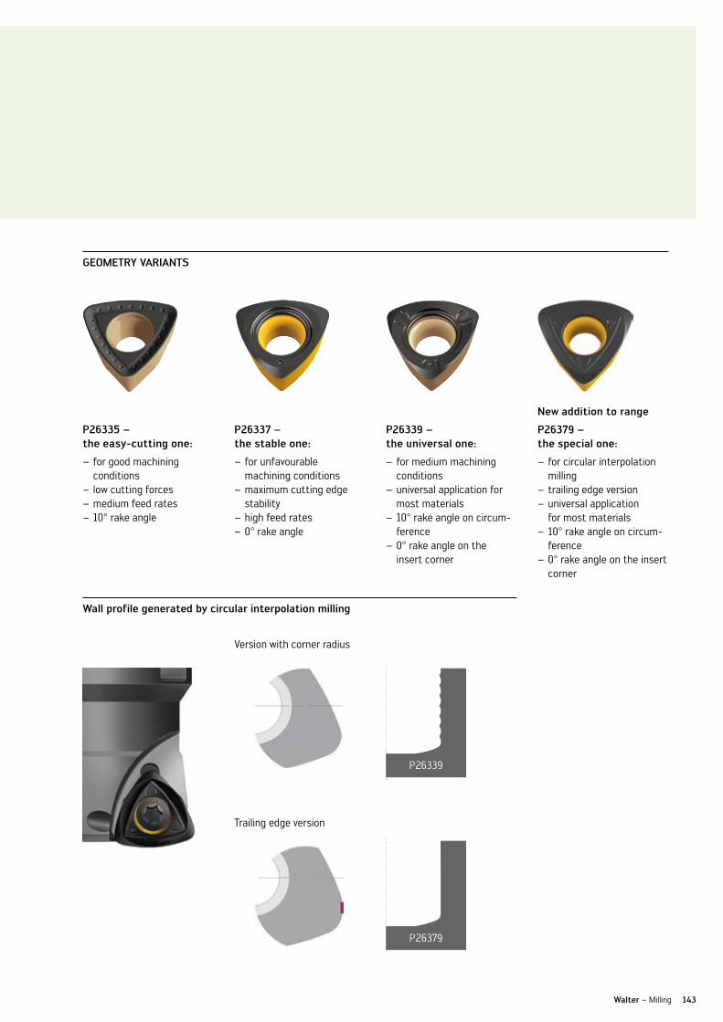
143Walter – Milling
gEoMETry varianTs
Wall profile generated by circular interpolation milling
P26335 – the easy-cutting one:
for good machining – conditionslow cutting forces –medium feed rates –10° rake angle –
P26337 – the stable one:
for unfavourable – machining conditionsmaximum cutting edge –stabilityhigh feed rates –0° rake angle –
P26339 – the universal one:
for medium machining –conditionsuniversal application for –most materials10° rake angle on circum- –ference0° rake angle on the –insert corner
new addition to range
P26379 – the special one:
for circular interpolation –millingtrailing edge version –universal application –for most materials10° rake angle on circum- –ference0° rake angle on the insert –corner
version with corner radius
P26339
P26379
Trailing edge version

144
ThE varianTs
FACE MIllInG
Walter xtra·tec® f4033 face mill – 2 sizes, 8 cutting edges for maximum machined volume.
ThE Tools
Face mill, kappa 45° with quadratic indexable inserts –8 cutting edges per indexable insert due to negative basic –shapeExtremely soft cutting geometry –Two insert sizes for optimum fit to cutting depth –(6.5 mm and 9 mm)Indexable inserts with fully sintered and fully ground – circumferencesAlso available as a cartridge version F2010 –
aPPlicaTions
For all steel and cast iron workpieces, stainless steels –and difficult to cut materials, as well as non-ferrous metalsFor face milling, roughing and roughing-finishing with –wiper insertsFor use in general engineering and the –automotive industry
your aDvanTagEs
High machining volume, even from low-performance – machines, thanks to positive, soft cutting actionHigh level of process reliability thanks to stable, negative –indexable insertslow cutting tool material costs due to 8-edge indexable –insertsMaximum productivity from the universal use of –Tiger·tec® coatings
Hard-nickel plated surface
8 cutting edges
2 indexable insert sizes
xtra·tec® face milling cutter f4033...06 apmax = 6.5 mm
Indexable insert size Sn . X1205Ann … –Ø 40 – 200 mm –Three pitches available –
xtra·tec® face milling cutter f4033...09 apmax = 9 mm
Indexable insert size Sn . X1606Ann … –Ø 50 – 200 mm –One pitch available –
Ordering information for F4033 … 09: see Walter Supplement Catalogue 2009.

D27
f27
f67
f57
k88
145Walter – Milling
gEoMETry varianTs
new addition to range
D27 – the special one:
for machining cast iron materials –for sand inclusions or casting skin –maximum process reliability –10° rake angle –
f27 – the stable one:
for unfavourable machining conditions –maximum cutting edge stability –high feed rates –16° rake angle –
f57 – the universal one:
for medium machining conditions –universal application for most materials –16° rake angle –
f67 – the easy-cutting one:
for good machining conditions –low cutting forces –medium feed rates –16° rake angle –
k88 – the sharp one:
for machining aluminium –low cutting forces –sharp cutting edges –22° rake angle –
* available for F4033 … 06
F27
F57
F67
D27
F67* Wiper insert
K88*

SuBlInE üBER HEADlInE (1.1)
headline in grün (1.2), auch für umbrüche als 3- Zeiler möglich. headline in grün, auch für umbrüche als 3- Zeiler möglich.
146 Walter – Kapitelbereich
SIDE AnD FACE MIllInG CuTTER
Walter xtra·tec® side and face milling cutter range – extremely productive and cost-effective.
xtra·tec® side and face milling cutter range Types: F 4253, F 4153, F 4053
Adjusting screws for runout
Hard-nickel plated surface
4 mm cutting width
ThE Tools
Side and face milling cutter with – cutting widths of 4 to 25 mmØ 80 – 315 mm –Tangential indexable inserts with four –edges, in 2 geometriesIndexable inserts with fully ground and –sintered circumferenceHard-nickel plated surface provides –protection from corrosion and wear, and ensures better chip flow
aPPlicaTions
For all steel and cast iron materials, –as well as for stainless steels and difficult to cut materials For separating, slitting, grooving and –shouldering operationsFor roughing and finishing operations –Ideally suited for use in general me- –chanical engineering, the automobile industry and aerospace applications
your aDvanTagEs
High machining volume, even from –low-performance machines, thanks to positive, soft cutting actionHigh process reliability due to stable –tangential indexable insertslow cutting material costs due to –indexable inserts with 4 cutting edgesSystem indexable inserts: one type –of indexable insert for several cut-ting widthsMaximum productivity from the uni- –versal use of Tiger·tec® coatings

SuBlInE üBER HEADlInE (1.1)
headline in grün (1.2), auch für umbrüche als 3- Zeiler möglich. headline in grün, auch für umbrüche als 3- Zeiler möglich.
147Walter – Kapitelbereich
ThE aDaPTors
cylindrical hole with longitudinal key way according to Din 138
Suitable for gang milling –cutterFor use with thrust bearing –Drive via key –
cylindrical hole with transverse key way according to Din 138
Clamping from front –no protrusions causing –interference on the front faceDrive via dogs –
casings:finishing adaptor groove
cutting data
current (sc brazed) WKP35vc 50 m/min 160 m/minfz 0.027 mm 0.15 mmvf 253 mm/min 509 mm/minap 16 mm 16 mmae 0.1 mm 0.1 mm
comparison of machining costs per component
0
Rz = 4 - 6 µm
100 200 300 400
Current € 381.00
-90%
Workpiece material: 31CrMo12 (1.8515), ISO PTool: F4253 / SB 16 / Z 5 / Ø 100 mmindexable insert: lnHu 080408–F57Tcutting tool material: WSM35
WKP35 37.52 €
ThE aDjusTabiliTy
Type F4253 –Simple adjustment of the runout –with µ accuracy using adjusting screwsTorxPlus screws for best handling –High-quality surface finishes pos- –sible thanks to adjustable runout
Walter – Milling

148
SHOulDER MIllInG CuTTER
Walter xtra·tec® shoulder milling cutter f4042r with indexable insert size aDMT 10T3 – stabilised for maximum process reliability.
ThE Tools
Shoulder milling cutter with indexable insert –size AD . T 10T3… for 10 mm cutting depthlead angle exactly 90° –Stabilised design for excellent process – reliability and maximum cutting efficiencyF4042R, R = reinforced –Ø 16 - 63 mm or 5/8 - 2 inches –Three insert pitches for different applica- –tionsAs arbour mounted tool, with weldon shank, –cylindrical shank or with modular ScrewFit interface
aPPlicaTions
Particularly suitable for difficult to cut –materials, e.g. titanium, InconelFor steel and cast iron materials as well as –for stainless steels and non-ferrous metalsFor slot milling, shoulder milling, pocket – milling and trimmingFor applications in general mechanical – engineering, and in the aerospace and energy industries
your aDvanTagEs
High machining volume, even from –low-performance machines, thanks to positive, soft cutting actionReduced machining costs thanks to –step-free millingHigh process reliability due to stabilised –designReduced inventory costs: ideal applica- –tion of the tool on various materials thanks to the variety of geometries and cutting material grades
Hard-nickel plated body
Indexable insert size AD . T 10T3...
Indexable insert size AD . T 10T3...
Stabilised design
Stabilised design
Modular ScrewFit interface
xtra·tec® shoulder milling range Type: F 4042R

f56
g56
D67g77
g88
149
ThE PiTch
Walter – Milling
gEoMETry varianTs
new addition to range
D67 – the powerful one:
high cutting edge stability –for machining high alloy –and high tensile steels and ni-based alloys, e.g. Inconelhigh level of accuracy –10° rake angle –
f56 – the universal one:
for medium machining –conditionsuniversal application for –most materials16° rake angle –
g56 – the easy-cutting one:
for good machining – conditionslow cutting forces –medium feed rates –20° rake angle –
new addition to range
g77 – the special one:
for machining titanium –materialslow cutting forces –high level of accuracy –20° rake angle –
g88 – the sharp one:
for machining aluminium –low cutting forces –sharp cutting edges –20° rake angle –
Wide pitch
for low-performance –machinesfor long projection lengths –for slot milling –
Medium pitch
for universal application –for machining most – materials
close pitch
for trimming with high –feed ratesfor stable conditions –for machining cast iron –materials

l88 k88g88
150
FACE AnD SHOulDER MIllS
Walter xtra·tec® milling cutters for aluminium machining – sharp and productive.
aDhT . . -g88 for xtra·tec® shoulder milling cutter f4042
Rhombic, positive basic shape –Two cutting edges per indexable insert –Three indexable insert sizes –Corner radii from 0.4 to 4.0 mm –
snhx . . –k88 for xtra·tec® face milling cutter f4033
Square, negative basic shape –Eight cutting edges per insert –One indexable insert size –Corner facets for excellent surface finish –
lngx 1307 . . -l88 for xtra·tec® shoulder milling cutter f4041
Rhombic, negative basic shape –Four cutting edges per indexable insert –One indexable insert size –Corner radii from 0.8 to 3.0 mm –
ThE gEoMETriEs
l88 / g88 / k88 – the sharp ones
For machining aluminium –low cutting forces –Sharp cutting edges –28° / 20° / 22° rake angle –
ThE inDExablE insErT
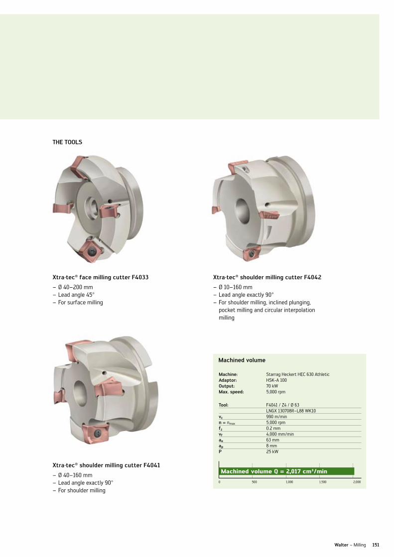
151Walter – Milling
xtra·tec® face milling cutter f4033
Ø 40–200 mm –lead angle 45° –For surface milling –
xtra·tec® shoulder milling cutter f4041
Ø 40–160 mm –lead angle exactly 90° –For shoulder milling –
xtra·tec® shoulder milling cutter f4042
Ø 10–160 mm –lead angle exactly 90° –For shoulder milling, inclined plunging, –pocket milling and circular interpolation milling
Machined volume
0 500 1,000 2,0001,500
Machined volume Q = 2,017 cm³/min
Tool: F4041 / Z4 / Ø 63 lnGX 130708R–l88 WK10vc 990 m/minn = nmax 5,000 rpmfz 0.2 mmvf 4,000 mm/minae 63 mmap 8 mmP 25 kW
Machine: Starrag Heckert HEC 630 Athleticadaptor: HSK-A 100output: 70 kWMax. speed: 5,000 rpm
ThE Tools

ORDER InFORMATIOn
152
Walter xtra·tec® high Performance mill f4030
Designationinch series
Da mm
Dc mm
d1 mm
x1 mm
x2 mm
lc mm
ae mm Z kg
no. of index-able
insertsinsert type
screw type
★ F4030.B22.050.Z04.01 50 38.4 22 40 1 10 4 0.4 4
P23696-1.0 FS1494
★ F4030.B22.050.Z05.01 50 38.4 22 40 1 10 5 0.3 5
★ F4030.B22.052.Z04.01 52 40.4 22 40 1 10 4 0.4 4
★ F4030.B22.063.Z05.01 63 51.4 22 50 1 10 5 0.7 5
★ F4030.B22.063.Z06.01 63 51.4 22 50 1 10 6 0.7 6
★ F4030.T22.025.Z02.01 25 13.4 22 35 1 10 2 0.1 2
★ F4030.T28.032.Z03.01 32 20.4 28 40 1 10 3 0.2 3
★ F4030.T28.035.Z03.01 35 23.4 28 40 1 10 3 0.2 3
★ F4030.T36.040.Z03.01 40 28.4 36 40 1 10 3 0.3 3
★ F4030.T36.040.Z04.01 40 28.4 36 40 1 10 4 0.3 4
★ F4030.T36.042.Z03.01 42 30.4 36 40 1 10 3 0.4 3
Walter xtra·tec® high Performance mill f4030
Designationinch series
Da mm
Dc mm
d1 mm
x1 mm
x2 mm
lc mm
ae mm Z kg
no. of index-able
insertsinsert type
screw type
★ F4030.uT22.026.Z02.01 25.4 13.8 22 35 1 10 2 0.1 2
P23696-1.0 FS1494
★ F4030.uT28.031.Z03.01 31.75 20.15 28 40 1 10 3 0.2 3
★ F4030.uT36.038.Z03.01 38.1 26.5 36 40 1 10 3 0.3 3
★ F4030.uW19.026.Z02.01 25.4 13.8 19.05 104.7 1 10 2 0.2 2
★ F4030.uW26.031.Z03.01 31.75 20.15 25.4 111 1 10 3 0.4 3
★ F4030.uW31.038.Z03.01 38.1 26.5 31.75 111 1 10 3 0.6 3
★ F4030.uZ19.026.Z02.01 25.4 13.8 19.05 203.2 1 10 2 0.4 2
★ F4030.uZ26.031.Z03.01 31.75 20.15 25.4 254 1 10 3 1.0 3
★ F4030.uZ31.038.Z03.01 38.1 26.5 31.75 254 1 10 3 1.5 3
★ F4030.uB19.051.Z05.01 50.8 39.2 19.05 40 1 10 5 0.4 5
★ F4030.uB26.064.Z05.01 63.5 51.9 25.4 50 1 10 5 0.7 5
★ F4030.uB26.064.Z06.01 63.5 51.9 25.4 50 1 10 6 0.7 6
NEW2010
NEW2010
★ new addition to range
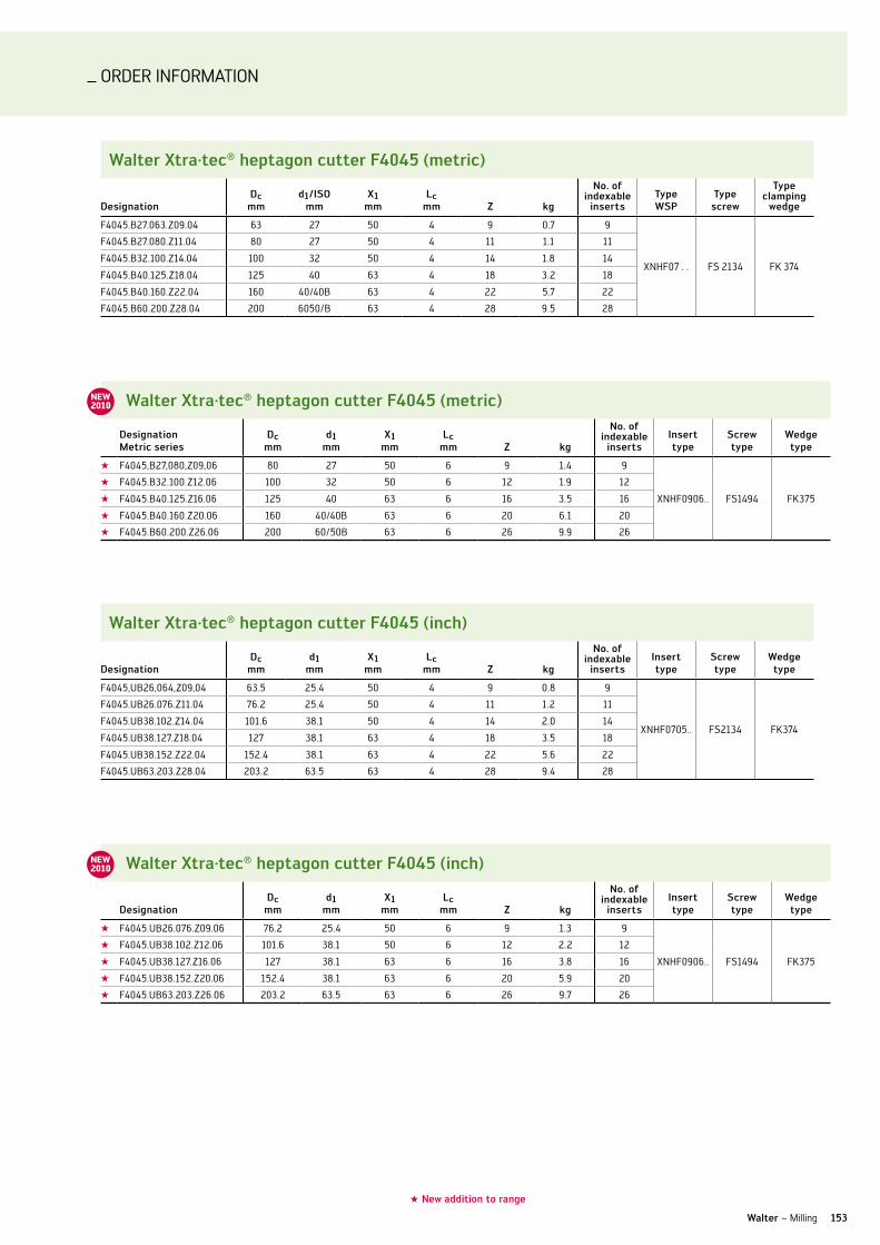
ORDER InFORMATIOn
153Walter – Milling
Walter xtra·tec® heptagon cutter f4045 (metric)
DesignationDc
mmd1/iso
mmx1
mmlc
mm Z kg
no. of indexable
insertsType WsP
Type screw
Type clamping
wedge
F4045.B27.063.Z09.04 63 27 50 4 9 0.7 9
XnHF07 . . FS 2134 FK 374
F4045.B27.080.Z11.04 80 27 50 4 11 1.1 11
F4045.B32.100.Z14.04 100 32 50 4 14 1.8 14
F4045.B40.125.Z18.04 125 40 63 4 18 3.2 18
F4045.B40.160.Z22.04 160 40/40B 63 4 22 5.7 22
F4045.B60.200.Z28.04 200 6050/B 63 4 28 9.5 28
Walter xtra·tec® heptagon cutter f4045 (inch)
Designation Dc
mmd1
mmx1
mmlc
mm Z kg
no. of indexable
insertsinsert type
screw type
Wedge type
★ F4045.uB26.076.Z09.06 76.2 25.4 50 6 9 1.3 9
XnHF0906.. FS1494 FK375
★ F4045.uB38.102.Z12.06 101.6 38.1 50 6 12 2.2 12
★ F4045.uB38.127.Z16.06 127 38.1 63 6 16 3.8 16
★ F4045.uB38.152.Z20.06 152.4 38.1 63 6 20 5.9 20
★ F4045.uB63.203.Z26.06 203.2 63.5 63 6 26 9.7 26
Walter xtra·tec® heptagon cutter f4045 (metric)
Designation Metric series
Dc mm
d1 mm
x1 mm
lc mm Z kg
no. of indexable
insertsinsert type
screw type
Wedge type
★ F4045,B27,080,Z09,06 80 27 50 6 9 1.4 9
XnHF0906.. FS1494 FK375
★ F4045.B32.100.Z12.06 100 32 50 6 12 1.9 12
★ F4045.B40.125.Z16.06 125 40 63 6 16 3.5 16
★ F4045.B40.160.Z20.06 160 40/40B 63 6 20 6.1 20
★ F4045.B60.200.Z26.06 200 60/50B 63 6 26 9.9 26
Walter xtra·tec® heptagon cutter f4045 (inch)
DesignationDc
mmd1
mmx1
mmlc
mm Z kg
no. of indexable
insertsinsert type
screw type
Wedge type
F4045,uB26,064,Z09,04 63.5 25.4 50 4 9 0.8 9
XnHF0705.. FS2134 FK374
F4045.uB26.076.Z11.04 76.2 25.4 50 4 11 1.2 11
F4045.uB38.102.Z14.04 101.6 38.1 50 4 14 2.0 14
F4045.uB38.127.Z18.04 127 38.1 63 4 18 3.5 18
F4045.uB38.152.Z22.04 152.4 38.1 63 4 22 5.6 22
F4045.uB63.203.Z28.04 203.2 63.5 63 4 28 9.4 28
NEW2010
NEW2010
★ new addition to range

ORDER InFORMATIOn
154
Walter xtra·tec® toric profile mill f4031 (metric)
DesignationDc
mmrmax mm
d1 mm
x1 mm
x2 mm
x3 mm Z kg
no. of indexable
insertsType WsP
Type screw
F4031.T14.012.Z02.20 12 2.0 14.5 25 — — 2 0.1 1P8001–D12R . . P8001–uD4R . .
FS 2072
F4031.T14.016.Z02.25 16 2.5 14.5 25 — — 2 0.1 1P8001–D16R . . P8001–uD5R . .
FS 2073
F4031.T18.020.Z02.32 20 3.2 18.5 30 — — 2 0.1 1P8001–D20R . . P8001–uD6R . .
FS 2074
F4031.T22.025.Z02.40 25 4.0 22 35 — — 2 0.1 1P8001–D25R . . P8001–uD8R . .
FS 2075
F4031.T28.032.Z02.50 32 5 28 40 — — 2 0.2 1 P8001–D32R . . P8001–uD10R . .
FS 2107
F4031.Z12.012.Z02.20 12 2.0 12 — 130 32 2 0.2 1P8001–D12R . . P8001–uD4R . . FS 2072
F4031.Z16.016.Z02.25 16 2.5 16 — 140 40 2 0.2 1 P8001–D16R . . P8001–uD5R . . FS 2073
F4031.Z20.020.Z02.32 20 3.2 20 — 160 50 2 0.4 1 P8001–D20R . . P8001–uD6R . . FS 2074
F4031.Z25.025.Z02.40 25 4.0 25 — 160 63 2 0.6 1 P8001–D25R . . P8001–uD8R . . FS 2075
F4031.Z32.032.Z02.50 32 5 32 — 180 80 2 1.0 1 P8001–D32R . . P8001–uD10R . . FS 2107
Walter xtra·tec® toric profile mill f4031 (inches)
DesignationDc
mmrmax mm
d1 mm
x2 mm
x3 mm Z kg
no. of indexable
insertsType WsP
Type screw
F4031.uZ13.012.Z02.20 12.7 2 12.7 130 32 2 0.2 1P8001–D12R . . P8001–uD4R . . FS 2072
F4031.uZ15.016.Z02.25 15.88 2.5 15.88 140 40 2 0.2 1 P8001–D16R . . P8001–uD5R . . FS 2073
F4031.uZ19.020.Z02.32 19.05 3.2 19.05 160 50 2 0.4 1 P8001–D20R . . P8001–uD6R . . FS 2074
F4031.uZ26.025.Z02.40 25.4 4 25.4 160 63 2 0.6 1 P8001–D25R . . P8001–uD8R . . FS 2075
F4031.uZ31.032.Z02.50 31.75 5 31.75 180 80 2 1.0 1 P8001–D32R . . P8001–uD10R . . FS 2107
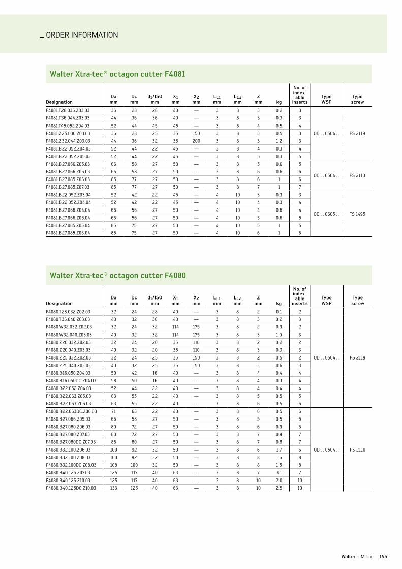
ORDER InFORMATIOn
155Walter – Milling
Walter xtra·tec® octagon cutter f4081
DesignationDa mm
Dc mm
d1/iso mm
x1 mm
x2 mm
lc1 mm
lc2 mm
Zmm kg
no. of index-able
insertsType WsP
Type screw
F4081.T28.036.Z03.03 36 28 28 40 — 3 8 3 0.2 3
OD . . 0504 . . FS 2119
F4081.T36.044.Z03.03 44 36 36 40 — 3 8 3 0.3 3
F4081.T45.052.Z04.03 52 44 45 45 — 3 8 4 0.5 4
F4081.Z25.036.Z03.03 36 28 25 35 150 3 8 3 0.5 3
F4081.Z32.044.Z03.03 44 36 32 35 200 3 8 3 1.2 3
F4081.B22.052.Z04.03 52 44 22 45 — 3 8 4 0.3 4
F4081.B22.052.Z05.03 52 44 22 45 — 3 8 5 0.3 5
F4081.B27.066.Z05.03 66 58 27 50 — 3 8 5 0.6 5
OD . . 0504 . . FS 2110F4081.B27.066.Z06.03 66 58 27 50 — 3 8 6 0.6 6
F4081.B27.085.Z06.03 85 77 27 50 — 3 8 6 1 6
F4081.B27.085.Z07.03 85 77 27 50 — 3 8 7 1 7
F4081.B22.052.Z03.04 52 42 22 45 — 4 10 3 0.3 3
OD . . 0605 . . FS 1495
F4081.B22.052.Z04.04 52 42 22 45 — 4 10 4 0.3 4
F4081.B27.066.Z04.04 66 56 27 50 — 4 10 4 0.6 4
F4081.B27.066.Z05.04 66 56 27 50 — 4 10 5 0.6 5
F4081.B27.085.Z05.04 85 75 27 50 — 4 10 5 1 5
F4081.B27.085.Z06.04 85 75 27 50 — 4 10 6 1 6
Walter xtra·tec® octagon cutter f4080
DesignationDa mm
Dc mm
d1/iso mm
x1 mm
x2 mm
lc1 mm
lc2 mm
Zmm kg
no. of index-able
insertsType WsP
Type screw
F4080.T28.032.Z02.03 32 24 28 40 — 3 8 2 0.1 2
OD . . 0504 . . FS 2119
F4080.T36.040.Z03.03 40 32 36 40 — 3 8 3 0.2 3
F4080.W32.032.Z02.03 32 24 32 114 175 3 8 2 0.9 2
F4080.W32.040.Z03.03 40 32 32 114 175 3 8 3 1.0 3
F4080.Z20.032.Z02.03 32 24 20 35 110 3 8 2 0.2 2
F4080.Z20.040.Z03.03 40 32 20 35 110 3 8 3 0.3 3
F4080.Z25.032.Z02.03 32 24 25 35 150 3 8 2 0.5 2
F4080.Z25.040.Z03.03 40 32 25 35 150 3 8 3 0.6 3
F4080.B16.050.Z04.03 50 42 16 40 — 3 8 4 0.4 4
F4080.B16.050DC.Z04.03 58 50 16 40 — 3 8 4 0.3 4
F4080.B22.052.Z04.03 52 44 22 40 — 3 8 4 0.4 4
F4080.B22.063.Z05.03 63 55 22 40 — 3 8 5 0.5 5
F4080.B22.063.Z06.03 63 55 22 40 — 3 8 6 0.5 6
F4080.B22.063DC.Z06.03 71 63 22 40 — 3 8 6 0.5 6
OD . . 0504 . . FS 2110
F4080.B27.066.Z05.03 66 58 27 50 — 3 8 5 0.5 5
F4080.B27.080.Z06.03 80 72 27 50 — 3 8 6 0.9 6
F4080.B27.080.Z07.03 80 72 27 50 — 3 8 7 0.9 7
F4080.B27.080DC.Z07.03 88 80 27 50 — 3 8 7 0.8 7
F4080.B32.100.Z06.03 100 92 32 50 — 3 8 6 1.7 6
F4080.B32.100.Z08.03 100 92 32 50 — 3 8 8 1.6 8
F4080.B32.100DC.Z08.03 108 100 32 50 — 3 8 8 1.5 8
F4080.B40.125.Z07.03 125 117 40 63 — 3 8 7 3.1 7
F4080.B40.125.Z10.03 125 117 40 63 — 3 8 10 2.0 10
F4080.B40.125DC.Z10.03 133 125 40 63 — 3 8 10 2.5 10

ORDER InFORMATIOn
156
Walter xtra·tec® porcupine cutter f4338 (metric)
DesignationDc
mmd1
mmx1
mmlc
mm Z kg
no. of indexable
insertsType WsP
Type screw
F4338.B27.063.Z04.31 63 27 53 31 4 0.6 8
AD . . 1807 . . FS 1495
F4338.B27.063.Z04.47 63 27 69 47 4 0.7 12
F4338.B27.063.Z04.63 63 27 85 63 4 0.9 16
F4338.B32.080.Z05.31 80 32 53 31 5 1.1 10
F4338.B32.080.Z05.63 80 32 85 63 5 1.7 20
F4338.B32.080.Z05.78 80 32 100 78 5 2.0 25
F4338.B40.100.Z05.78 100 40 105 78 5 3.6 25
F4338.B40.125.Z06.94 125 40 120 94 6 7.5 36
Walter xtra·tec® porcupine cutter f4138 (metric)
DesignationDc
mmd1
mmx1
mmx2
mmlc
mm Z kg
no. of indexable
insertsType WsP
Type screw
F4138.n8.050.Z04.65 50 80 116 80 65 4 1.7 24
AD . . 1204 . . FS 1457
F4138.n8.063.Z05.76 63 80 125 99 76 5 2.5 35
F4138.B16.040.Z03.43 40 16 65 — 43 3 0.3 9
F4138.B22.050.Z04.54 50 22 75 — 54 4 0.6 20
F4138.B27.063.Z05.54 63 27 80 — 54 5 1.1 25
F4138.B32.080.Z06.65 80 32 95 — 65 6 2.3 36
Walter xtra·tec® porcupine cutter f4238 (metric)
DesignationDc
mmd1
mmx1
mmx2
mmlc
mm Z kg
no. of indexable
insertsType WsP
Type screw
F4238.S4.040.Z03.29 40 SK40 75 54 29 3 1.1 6
AD . . 1606 . . FS 1453
F4238.S4.050.Z03.43 50 SK40 85 65 43 3 1.4 9
F4238.S5.050.Z03.85 50 SK50 140 106 85 3 3.7 18
F4238.S5.063.Z03.99 63 SK50 153 121 99 3 4.4 21
F4238.S5.080.Z04.112 80 SK50 163 138 112 4 6.0 32
F4238.n6.040.Z03.57 40 63 108 80 57 3 1.0 12
F4238.n8.050.Z03.71 50 80 122 93 71 3 1.9 15
F4238.n8.063.Z04.85 63 80 136 111 85 4 2.6 24
F4238.n8.080.Z05.99 80 80 150 130 99 5 4.2 35
F4238.B27.063.Z04.57 63 27 85 — 57 4 1.1 16
F4238.B27.066.Z04.57 66 27 85 — 57 4 1.3 16
F4238.B32.080.Z05.71 80 32 100 — 71 5 2.3 25
F4238.B32.085.Z05.71 85 32 100 — 71 5 2.8 25
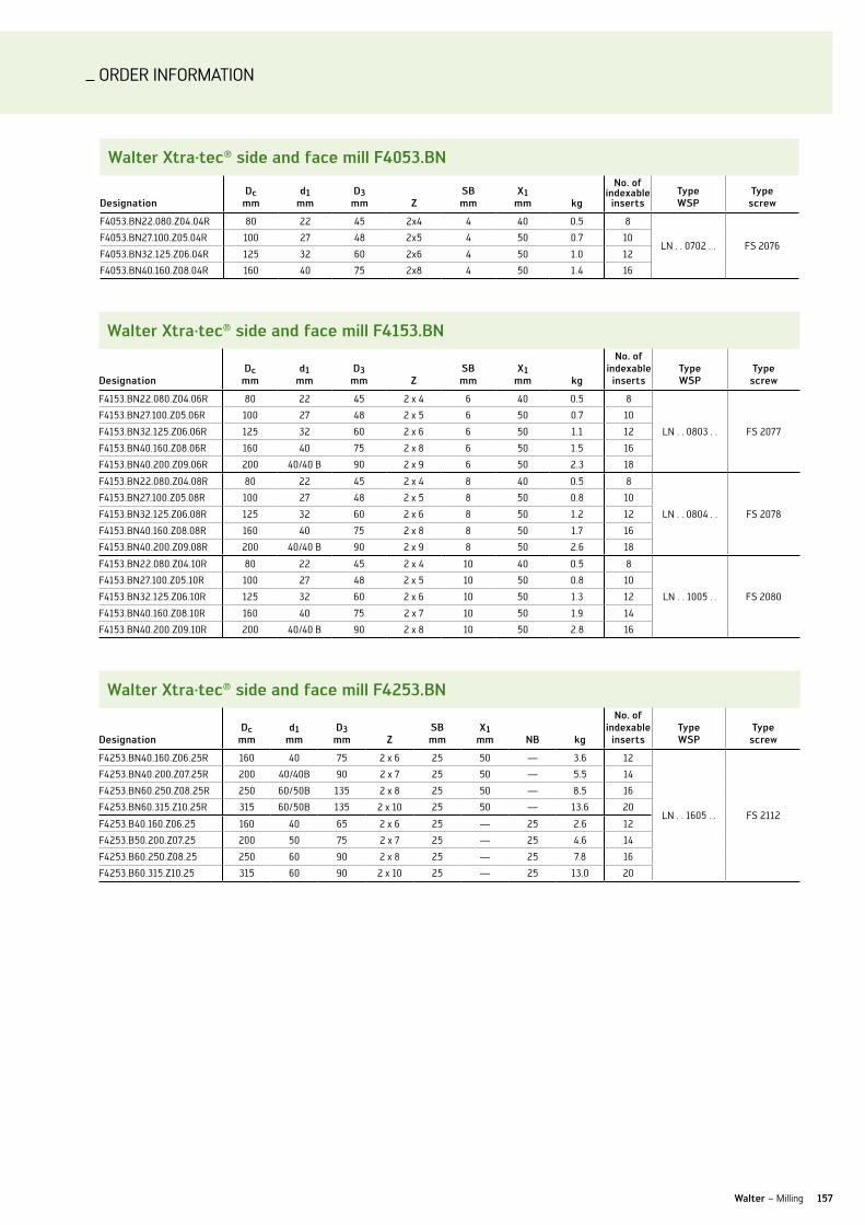
ORDER InFORMATIOn
157Walter – Milling
Walter xtra·tec® side and face mill f4053.bn
DesignationDc
mmd1
mmD3
mm Zsb mm
x1 mm kg
no. of indexable
insertsType WsP
Type screw
F4053.Bn22.080.Z04.04R 80 22 45 2x4 4 40 0.5 8
ln . . 0702 . . FS 2076F4053.Bn27.100.Z05.04R 100 27 48 2x5 4 50 0.7 10
F4053.Bn32.125.Z06.04R 125 32 60 2x6 4 50 1.0 12
F4053.Bn40.160.Z08.04R 160 40 75 2x8 4 50 1.4 16
Walter xtra·tec® side and face mill f4153.bn
DesignationDc
mmd1
mmD3
mm Zsb mm
x1 mm kg
no. of indexable
insertsType WsP
Type screw
F4153.Bn22.080.Z04.06R 80 22 45 2 x 4 6 40 0.5 8
ln . . 0803 . . FS 2077
F4153.Bn27.100.Z05.06R 100 27 48 2 x 5 6 50 0.7 10
F4153.Bn32.125.Z06.06R 125 32 60 2 x 6 6 50 1.1 12
F4153.Bn40.160.Z08.06R 160 40 75 2 x 8 6 50 1.5 16
F4153.Bn40.200.Z09.06R 200 40/40 B 90 2 x 9 6 50 2.3 18
F4153.Bn22.080.Z04.08R 80 22 45 2 x 4 8 40 0.5 8
ln . . 0804 . . FS 2078
F4153.Bn27.100.Z05.08R 100 27 48 2 x 5 8 50 0.8 10
F4153.Bn32.125.Z06.08R 125 32 60 2 x 6 8 50 1.2 12
F4153.Bn40.160.Z08.08R 160 40 75 2 x 8 8 50 1.7 16
F4153.Bn40.200.Z09.08R 200 40/40 B 90 2 x 9 8 50 2.6 18
F4153.Bn22.080.Z04.10R 80 22 45 2 x 4 10 40 0.5 8
ln . . 1005 . . FS 2080
F4153.Bn27.100.Z05.10R 100 27 48 2 x 5 10 50 0.8 10
F4153.Bn32.125.Z06.10R 125 32 60 2 x 6 10 50 1.3 12
F4153.Bn40.160.Z08.10R 160 40 75 2 x 7 10 50 1.9 14
F4153.Bn40.200.Z09.10R 200 40/40 B 90 2 x 8 10 50 2.8 16
Walter xtra·tec® side and face mill f4253.bn
DesignationDc
mmd1
mmD3
mm Zsb mm
x1 mm nb kg
no. of indexable
insertsType WsP
Type screw
F4253.Bn40.160.Z06.25R 160 40 75 2 x 6 25 50 — 3.6 12
ln . . 1605 . . FS 2112
F4253.Bn40.200.Z07.25R 200 40/40B 90 2 x 7 25 50 — 5.5 14
F4253.Bn60.250.Z08.25R 250 60/50B 135 2 x 8 25 50 — 8.5 16
F4253.Bn60.315.Z10.25R 315 60/50B 135 2 x 10 25 50 — 13.6 20
F4253.B40.160.Z06.25 160 40 65 2 x 6 25 — 25 2.6 12
F4253.B50.200.Z07.25 200 50 75 2 x 7 25 — 25 4.6 14
F4253.B60.250.Z08.25 250 60 90 2 x 8 25 — 25 7.8 16
F4253.B60.315.Z10.25 315 60 90 2 x 10 25 — 25 13.0 20
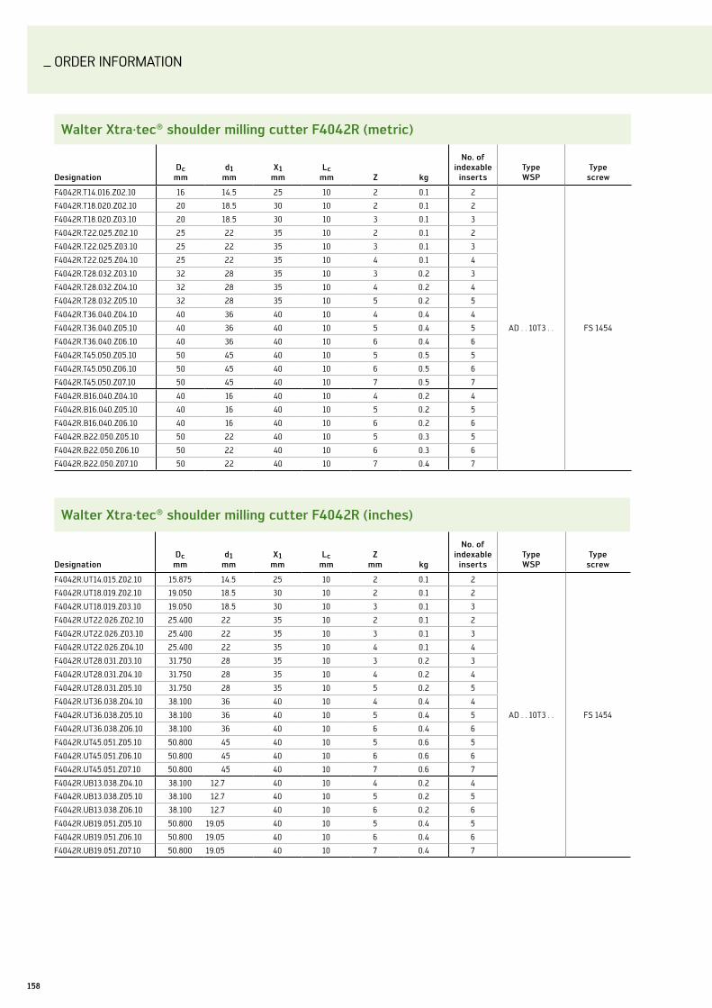
ORDER InFORMATIOn
158
Walter xtra·tec® shoulder milling cutter f4042r (metric)
DesignationDc
mmd1
mmx1
mmlc
mm Z kg
no. of indexable
insertsType WsP
Type screw
F4042R.T14.016.Z02.10 16 14.5 25 10 2 0.1 2
AD . . 10T3 . . FS 1454
F4042R.T18.020.Z02.10 20 18.5 30 10 2 0.1 2
F4042R.T18.020.Z03.10 20 18.5 30 10 3 0.1 3
F4042R.T22.025.Z02.10 25 22 35 10 2 0.1 2
F4042R.T22.025.Z03.10 25 22 35 10 3 0.1 3
F4042R.T22.025.Z04.10 25 22 35 10 4 0.1 4
F4042R.T28.032.Z03.10 32 28 35 10 3 0.2 3
F4042R.T28.032.Z04.10 32 28 35 10 4 0.2 4
F4042R.T28.032.Z05.10 32 28 35 10 5 0.2 5
F4042R.T36.040.Z04.10 40 36 40 10 4 0.4 4
F4042R.T36.040.Z05.10 40 36 40 10 5 0.4 5
F4042R.T36.040.Z06.10 40 36 40 10 6 0.4 6
F4042R.T45.050.Z05.10 50 45 40 10 5 0.5 5
F4042R.T45.050.Z06.10 50 45 40 10 6 0.5 6
F4042R.T45.050.Z07.10 50 45 40 10 7 0.5 7
F4042R.B16.040.Z04.10 40 16 40 10 4 0.2 4
F4042R.B16.040.Z05.10 40 16 40 10 5 0.2 5
F4042R.B16.040.Z06.10 40 16 40 10 6 0.2 6
F4042R.B22.050.Z05.10 50 22 40 10 5 0.3 5
F4042R.B22.050.Z06.10 50 22 40 10 6 0.3 6
F4042R.B22.050.Z07.10 50 22 40 10 7 0.4 7
Walter xtra·tec® shoulder milling cutter f4042r (inches)
DesignationDc
mmd1
mmx1
mmlc
mmZ
mm kg
no. of indexable
insertsType WsP
Type screw
F4042R.uT14.015.Z02.10 15.875 14.5 25 10 2 0.1 2
AD . . 10T3 . . FS 1454
F4042R.uT18.019.Z02.10 19.050 18.5 30 10 2 0.1 2
F4042R.uT18.019.Z03.10 19.050 18.5 30 10 3 0.1 3
F4042R.uT22.026.Z02.10 25.400 22 35 10 2 0.1 2
F4042R.uT22.026.Z03.10 25.400 22 35 10 3 0.1 3
F4042R.uT22.026.Z04.10 25.400 22 35 10 4 0.1 4
F4042R.uT28.031.Z03.10 31.750 28 35 10 3 0.2 3
F4042R.uT28.031.Z04.10 31.750 28 35 10 4 0.2 4
F4042R.uT28.031.Z05.10 31.750 28 35 10 5 0.2 5
F4042R.uT36.038.Z04.10 38.100 36 40 10 4 0.4 4
F4042R.uT36.038.Z05.10 38.100 36 40 10 5 0.4 5
F4042R.uT36.038.Z06.10 38.100 36 40 10 6 0.4 6
F4042R.uT45.051.Z05.10 50.800 45 40 10 5 0.6 5
F4042R.uT45.051.Z06.10 50.800 45 40 10 6 0.6 6
F4042R.uT45.051.Z07.10 50.800 45 40 10 7 0.6 7
F4042R.uB13.038.Z04.10 38.100 12.7 40 10 4 0.2 4
F4042R.uB13.038.Z05.10 38.100 12.7 40 10 5 0.2 5
F4042R.uB13.038.Z06.10 38.100 12.7 40 10 6 0.2 6
F4042R.uB19.051.Z05.10 50.800 19.05 40 10 5 0.4 5
F4042R.uB19.051.Z06.10 50.800 19.05 40 10 6 0.4 6
F4042R.uB19.051.Z07.10 50.800 19.05 40 10 7 0.4 7

ORDER InFORMATIOn
159Walter – Milling
Walter f2339 (metric)
DesignationDc
mmr
mmd1
mmx1
mmx2
mmlc
mm Z kg
no. of indexable
insertsType WsP
Type screw
F2339.T14.016.Z02.11 16 8 14.5 25 — 11 2 0.1 2 XD . . 130080 . .
FS 1454
F2339.W16.016.Z02.11 16 8 16 25 74 11 2 0.1 2 XD . . 130080 . .
F2339.T14.016.Z02.24 16 8 14.5 40 — 24 2 0.1 2 2
XD . . 130080 . . SP . . 0603 . .
F2339.W16.016.Z02.24 16 8 16 40 89 24 2 0.1 2 2
XD . . 130080 . . SP . . 0603 . .
F2339.W20.016.Z02.24 16 8 16 40 91 24 2 0.2 2 2
XD . . 130080 . . SP . . 0603 . .
Walter f2339 (inches)
DesignationDc
mmr
mmd1
mmx1
mmx2
mmlc
mm Z kg
no. of indexable
insertsType WsP
Type screw
F2339.uT14.015.Z02.11 15.88 7.94 14.5 25 — 11 2 0.1 2 XD . . 130080 . .
FS 1454F2339.uW15.015.Z02.11 15.88 7.94 15.88 25 73.41 11 2 0.1 2 XD . . 130080 . .
F2339.uW15.015.Z02.24 15.88 7.94 15.88 40 88.41 11 2 0.1 2 2
XD . . 130080 . . SP . . 0603 . .
F2339.uW19.015.Z02.24 15.88 7.94 19.05 40 91.59 11 2 0.2 2 2
XD . . 130080 . . SP . . 0603 . .
Walter cartridge mill f2010
DesignationDc mm
Da mm
d1/iso mm
x1 mm
lc mm Z kg
no. of indexable
insertsType WsP
Type screw
Type cartridge
F2010.B.080.Z06.09.R732M 80 97 27 50 9 6 1.2 6
Sn . X1606 . . FS 2139 FR 732M
F2010.B.100.Z07.09.R732M 100 117 32 50 9 7 1.7 7
F2010.B.125.Z08.09.R732M 125 142 40 63 9 8 3.4 8
F2010.B.160.Z10.09.R732M 160 177 40/40 B 63 9 10 5.6 10
F2010.B.200.Z12.09.R732M 200 217 60/50 B 63 9 12 8.3 12
F2010.B.250.Z12.09.R732M 250 267 60/50 B 63 9 12 14.6 12
F2010.B.250.Z16.09.R732M 250 267 60/50 B 63 9 16 14.7 16
F2010.B.315.Z14.09.R732M 315 332 60/50 B 63 9 14 26.2 14
F2010.B.315.Z18.09.R732M 315 332 60/50 B 63 9 18 26.2 18
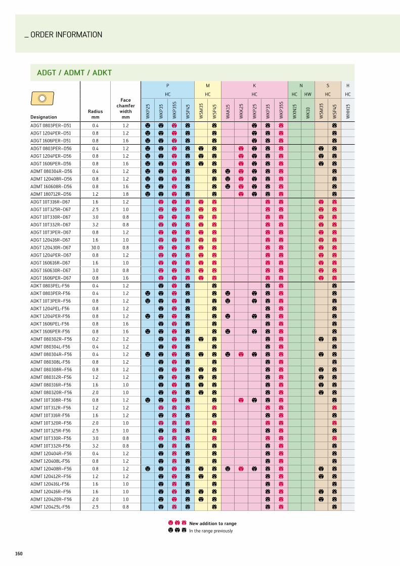
ORDER InFORMATIOn
160
aDgT / aDMT / aDkT
Designationradius
mm
face chamfer
width mm
P M K n S H
HC HC HC HC HW HC HC
WK
P25
WK
P35
WK
P35S
WSP
45
WSM
35
WSP
45
WA
K15
WK
K25
WK
P25
WK
P35
WK
P35S
WXn
15
WK
10
WSM
35
WSP
45
WH
H15
ADGT 0803PER–D51 0.4 1.2 a b b c c b c c c
ADGT 1204PER–D51 0.8 1.2 a b b c c b c c c
ADGT 1606PER–D51 0.8 1.6 a b b c c b c c c
ADGT 0803PER–D56 0.4 1.2 a b b c b c b b c c b c
ADGT 1204PER–D56 0.8 1.2 a b b c b c b b c c b c
ADGT 1606PER–D56 0.8 1.6 a b b c b c b b c c b c
ADMT 080304R–D56 0.4 1.2 a b b c c a b b c c c
ADMT 120408R–D56 0.8 1.2 a b b c c a b b c c c
ADMT 160608R–D56 0.8 1.6 a b b c c a b b c c c
ADMT 180712R–D56 1.2 1.8 a b b c c b b c c c
ADGT 10T316R–D67 1.6 1.2 b b c b c c c b c
ADGT 10T325R–D67 2.5 1.0 b b c b c c c b c
ADGT 10T330R–D67 3.0 0.8 b b c b c c c b c
ADGT 10T332R–D67 3.2 0.8 b b c b c c c b c
ADGT 10T3PER–D67 0.8 1.2 b b c b c c c b c
ADGT 120416R–D67 1.6 1.0 b b c b c c c b c
ADGT 120430R–D67 30.0 0.8 b b c b c c c b c
ADGT 1204PER–D67 0.8 1.2 b b c b c c c b c
ADGT 160616R–D67 1.6 1.0 b b c b c c c b c
ADGT 160630R–D67 3.0 0.8 b b c b c c c b c
ADGT 1606PER–D67 0.8 1.6 b b c b c c c b c
ADKT 0803PEl-F56 0.4 1.2 b b c c c c c
ADKT 0803PER-F56 0.4 1.2 a b b c c a b c c c
ADKT 10T3PER–F56 0.8 1.2 a b b c c a b c c c
ADKT 1204PEl-F56 0.8 1.2 b b c c c c c
ADKT 1204PER-F56 0.8 1.2 a b b c c a b c c c
ADKT 1606PEl-F56 0.8 1.6 b b c c c c c
ADKT 1606PER-F56 0.8 1.6 a b b c c a b c c c
ADMT 080302R–F56 0.2 1.2 b b c b c c c b c
ADMT 080304l-F56 0.4 1.2 b b c c c c c
ADMT 080304R–F56 0.4 1.2 a b b c b c a b b c c b c
ADMT 080308l-F56 0.8 1.2 b b c c c c c
ADMT 080308R–F56 0.8 1.2 b b c b c c c b c
ADMT 080312R–F56 1.2 1.2 b b c b c c c b c
ADMT 080316R–F56 1.6 1.0 b b c b c c c b c
ADMT 080320R–F56 2.0 1.0 b b c b c c c b c
ADMT 10T308R–F56 0.8 1.2 a b b c c b b c c c
ADMT 10T312R–F56 1.2 1.2 b c c c c c c
ADMT 10T316R-F56 1.6 1.2 b c c c c c c
ADMT 10T320R–F56 2.0 1.0 b c c c c c c
ADMT 10T325R-F56 2.5 1.0 b c c c c c c
ADMT 10T330R–F56 3.0 0.8 b c c c c c c
ADMT 10T332R-F56 3.2 0.8 b c c c c c c
ADMT 120404R–F56 0.4 1.2 b c c c c c c
ADMT 120408l-F56 0.8 1.2 b c c c c c c
ADMT 120408R–F56 0.8 1.2 a b b c b c a b b c c b c
ADMT 120412R–F56 1.2 1.2 b b c b c c c b c
ADMT 120416l-F56 1.6 1.0 b c c c c c c
ADMT 120416R–F56 1.6 1.0 b b c b c c c b c
ADMT 120420R–F56 2.0 1.0 b b c b c c c b c
ADMT 120425l-F56 2.5 0.8 b c c c c c c
a b c new addition to range
a b c In the range previously

ORDER InFORMATIOn
161Walter – Milling
a b c new addition to range
a b c In the range previously
aDgT / aDMT / aDkT
Designationradius
mm
face chamfer
width mm
P M K n S H
HC HC HC HC HW HC HC
WK
P25
WK
P35
WK
P35S
WSP
45
WSM
35
WSP
45
WA
K15
WK
K25
WK
P25
WK
P35
WK
P35S
WXn
15
WK
10
WSM
35
WSP
45
WH
H15
ADMT 120425R–F56 2.5 0.8 b b c b c c c b c
ADMT 120430l-F56 3.0 0.8 b c c c c c c
ADMT 120430R–F56 3.0 0.8 b b c b c c c b c
ADMT 120432R–F56 3.2 0.8 b b c b c c c b c
ADMT 120440l-F56 4.0 - b c c c c c c
ADMT120440R-F56 4.0 - b b c b c c c b c
ADMT 160608l-F56 0.8 1.6 b c c c c c c
ADMT 160608R–F56 0.8 1.6 a b b c b c a b b c c b c
ADMT 160612R–F56 1.2 1.6 b b c b c c c b c
ADMT 160616l-F56 1.6 1.4 b c c c c c c
ADMT 160616R–F56 1.6 1.4 b b c b c c c b c
ADMT 160620R–F56 2.0 1.4 b b c b c c c b c
ADMT 160625l-F56 2.5 1.2 b c c c c c c
ADMT 160625R–F56 2.5 1.2 b b c b c c c b c
ADMT 160630l-F56 3.0 1.2 b c c c c c c
ADMT 160630R–F56 3.0 1.2 b b c b c c c b c
ADMT 160632R–F56 3.2 1.2 b b c b c c c b c
ADMT 160640l-F56 4.0 1.0 b c c c c c c
ADMT160640R-F56 4.0 1.0 b b c b c c c b c
ADMT 160650R–F56 5.0 - b b c b c c c b c
ADMT 160660R–F56 6.0 - b b c b c c c b c
ADMT 180712R–F56 1.2 1.8 a b b c c b b c c c
ADMT 080304R-G56 0.4 1.2 b b c b c c c b c
ADMT 10T308R-G56 0.8 1.2 b b c b c c c b c
ADMT 10T316R-G56 1.6 1.2 b b c b c c c b c
ADMT 10T325R-G56 2.5 1.0 b b c b c c c b c
ADMT 10T332R-G56 3.2 0.8 b b c b c c c b c
ADMT 120408R-G56 0.8 1.2 b b c b c c c b c
ADMT 160608R-G56 0.8 1.6 b b c b c c c b c
ADGT 1807PER–D51 1.2 1.8 a b b c c b c c c
ADGT 10T3PER–G77 0.8 1.2 c b c b c
ADGT 1204PER–G77 0.8 1.2 c b c b c
ADGT 1606PER–G77 0.8 1.6 c b c b c
ADGT 10T316R–G77 1.6 1.2 c b c b c
ADGT 10T325R–G77 2.5 1.0 c b c b c
ADGT 10T330R–G77 3.0 0.8 c b c b c
ADGT 10T332R–G77 3.2 0.8 c b c b c
cnhu / cnMu
Designationradius
mm
face chamfer width mm
P M K n S H
HC HC HC HC HW HC HC
WK
P25
WK
P35
WSP
45
WSM
35
WSP
45
WA
K15
WK
K25
WK
P25
WK
P35
WXn
15
WK
10
WSM
35
WSP
45
WH
H15
CnHu 0805PPn–D57T 0.8 1.2 a b c b c a b c b c
CnHu 1206PPn–D57T 0.8 1.5 a b c b c a b c b c
CnHu 1608PPn–D57T 1.2 1.8 a b c b c a b c b c
CnMu 080508–D57T 0.8 — a b c b c b c b c
CnMu 120608–D57T 0.8 — a b c b c b c b c
CnMu 160812–D57T 1.2 — a b c b c b c b c

ORDER InFORMATIOn
162
lnhx / lnMx
Designationradius
mm
face chamfer
width mm
P M K n S H
HC HC HC HC HW HC HC
WK
P25
WK
P35
WK
P35S
WSP
45
WSM
35
WSP
45
WA
K15
WK
K25
WK
P25
WK
P35
WK
P35S
WXn
15
WK
10
WSM
35
WSP
45
WH
H15
lnMX 070204–D57T 0.4 b c c a b b c c
lnHX 070204–D57T 0.4 b c c a b b c c
lnMX 070204–F57T 0.4 a b b c b c b c c b c
lnHX 070204-F57T 0.4 a b b c b c b c c b c
lngx
Designationradius
mm
face chamfer
width mm
P M K n S H
HC HC HC HC HW HC HC
WK
P25
WK
P35
WK
P35S
WSP
45
WSM
35
WSP
45
WA
K15
WK
K25
WK
P25
WK
P35
WK
P35S
WXn
15
WK
10
WSM
35
WSP
45
WH
H15
lnGX 130708R-l55 0.8 1.2 a b b c b c a b b c c b c
lnGX 130712R-l55 1.2 1 a b b c b c b c c b c
lnGX 130716R-l55 1.6 0.9 a b b c b c b c c b c
lnGX 130720R-l55 2 0.7 a b b c b c b c c b c
lnGX 130725R-l55 2.5 0.6 a b b c b c b c c b c
lnGX 130730R-l55 3 0.5 a b b c b c b c c b c
lnGX 130730R-l88 3 0.5 a a
lnhu / lnMu
Designationradius
mm
face chamfer
width mm
P M K n S H
HC HC HC HC HW HC HC
WK
P25
WK
P35
WK
P35S
WSP
45
WSM
35
WSP
45
WA
K15
WK
K25
WK
P25
WK
P35
WK
P35S
WXn
15
WK
10
WSM
35
WSP
45
WH
H15
lnHu 080304-B57T 0.4 b c c a b b c c
lnHu 080404-B57T 0.4 b c c a b b c c
lnHu 100508-B57T 0.8 b c c a b b c c
lnHu 120608-B57T 0.8 b c c a b b c c
lnHu 160812-B57T 1.2 b c c a b c c
lnHu 160812–F57T 1.2 b b b c b c b c c b c
lnMu080304-B57T 0.4 b c c a b b c c
lnMu 080304–F57T 0.4 a b b c b c b c c b c
lnMu 080404-B57T 0.4 b c c a b b c c
lnMu 080404–F57T 0.4 a b b c b c b c c b c
lnMu 100508-B57T 0.8 b c c a b b c c
lnMu 100508–F57T 0.8 a b b c b c b b c b c
lnMu 120608-B57T 0.8 b c c a b b c c
lnMu 120608–F57T 0.8 a b b c b c b c c b c
lnMu 160812-B57T 1.2 b c c a b c c
lnMu 160812–F57T 1.2 b b b c b c b c c b c
a b c new addition to range
a b c In the range previously
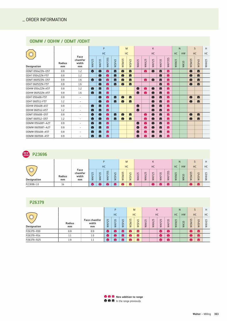
ORDER InFORMATIOn
163Walter – Milling
oDMW / oDhW / oDMT /oDhT
Designationradius
mm
face chamfer
width mm
P M K n S H
HC HC HC HC HW HC HC
WK
P25
WK
P35
WK
P35S
WSP
45
WSM
35
WSP
45
WA
K15
WK
K25
WK
P25
WK
P35
WK
P35S
WXn
15
WK
10
WSM
35
WSP
45
WH
H15
ODMT 0504ZZn–D57 0.8 1.2 a b b c b c b b c c b c
ODHT 0504ZZn-F57 0.8 1.2 b b c b c c c b c
ODMT 0605ZZn–D57 0.8 1.6 a b b c b c b b c c b c
ODHT 0605ZZn-F57 0.8 1.6 b b c b c c c b c
ODHW 0504ZZn-A57 0.8 1.2 b c c a b b c c
ODHW 0605ZZn-A57 0.8 1.6 b c c a b b c c
ODHT 050408-F57 0.8 - b b c b c b c c b c
ODHT 060512-F57 1.2 - b b c b c b c c b c
ODHW 050408-A57 0.8 - b c c a b c c
ODHW 060512-A57 1.2 - b c c a b c c
ODMT 050408–D57 0.8 - a b b c b c b b c c b c
ODMT 060512–D57 1.2 - a b b c b c b b c c b c
ODMW 050408T–A27 0.8 - b c c a b b c c
ODMW 060508T–A27 0.8 - b c c a b b c c
ODMW 050408–A57 0.8 - b c c a b b c c
ODMW 060508–A57 0.8 - b c c a b b c c
P23696
Designationradius
mm
face chamfer
width mm
P M K n S H
HC HC HC HC HW HC HC
WK
P25
WK
P35
WK
P35S
WSP
45
WSM
35
WSP
45
WA
K15
WK
K25
WK
P25
WK
P35
WK
P35S
WXn
15
WK
10
WSM
35
WSP
45
WH
H15
P23696-1.0 14 a b b c b c b c c b c
P26379
Designationradius
mm
face chamfer width mm
P M K n S H
HC HC HC HC HW HC HC
WK
P25
WK
P35
WSP
45
WSM
35
WSP
45
WA
K15
WK
K25
WK
P25
WK
P35
WXn
15
WK
10
WSM
35
WSP
45
WXH
15
P26379–R10 0.8 0.9 a b c b c a b b c
P26379–R14 1.1 1.0 a b c b c a b b c
P26379–R25 1.9 1.1 a b c b c a b b c
a b c new addition to range
a b c In the range previously
NEW2010
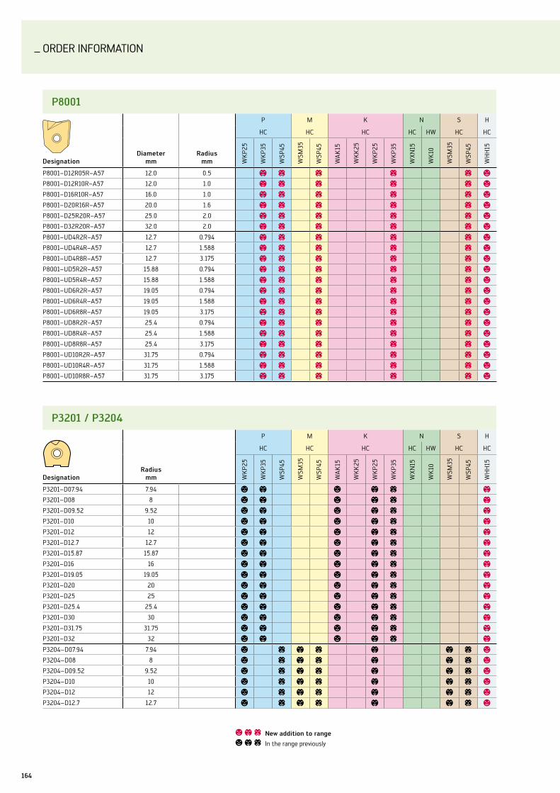
ORDER InFORMATIOn
164
P8001
DesignationDiameter
mmradius
mm
P M K n S H
HC HC HC HC HW HC HC
WK
P25
WK
P35
WSP
45
WSM
35
WSP
45
WA
K15
WK
K25
WK
P25
WK
P35
WXn
15
WK
10
WSM
35
WSP
45
WH
H15
P8001–D12R05R–A57 12.0 0.5 b c c c c a
P8001–D12R10R–A57 12.0 1.0 b c c c c a
P8001–D16R10R–A57 16.0 1.0 b c c c c a
P8001–D20R16R–A57 20.0 1.6 b c c c c a
P8001–D25R20R–A57 25.0 2.0 b c c c c a
P8001–D32R20R–A57 32.0 2.0 b c c c c a
P8001–uD4R2R–A57 12.7 0.794 b c c c c a
P8001–uD4R4R–A57 12.7 1.588 b c c c c a
P8001–uD4R8R–A57 12.7 3.175 b c c c c a
P8001–uD5R2R–A57 15.88 0.794 b c c c c a
P8001–uD5R4R–A57 15.88 1.588 b c c c c a
P8001–uD6R2R–A57 19.05 0.794 b c c c c a
P8001–uD6R4R–A57 19.05 1.588 b c c c c a
P8001–uD6R8R–A57 19.05 3.175 b c c c c a
P8001–uD8R2R–A57 25.4 0.794 b c c c c a
P8001–uD8R4R–A57 25.4 1.588 b c c c c a
P8001–uD8R8R–A57 25.4 3.175 b c c c c a
P8001–uD10R2R–A57 31.75 0.794 b c c c c a
P8001–uD10R4R–A57 31.75 1.588 b c c c c a
P8001–uD10R8R–A57 31.75 3.175 b c c c c a
P3201 / P3204
Designationradius
mm
P M K n S H
HC HC HC HC HW HC HC
WK
P25
WK
P35
WSP
45
WSM
35
WSP
45
WA
K15
WK
K25
WK
P25
WK
P35
WXn
15
WK
10
WSM
35
WSP
45
WH
H15
P3201–D07.94 7.94 a b a b c b
P3201–D08 8 a b a b c b
P3201–D09.52 9.52 a b a b c b
P3201–D10 10 a b a b c b
P3201–D12 12 a b a b c b
P3201–D12.7 12.7 a b a b c b
P3201–D15.87 15.87 a b a b c b
P3201–D16 16 a b a b c b
P3201–D19.05 19.05 a b a b c b
P3201–D20 20 a b a b c b
P3201–D25 25 a b a b c b
P3201–D25.4 25.4 a b a b c b
P3201–D30 30 a b a b c b
P3201–D31.75 31.75 a b a b c b
P3201–D32 32 a b a b c b
P3204–D07.94 7.94 a c b c b b c a
P3204–D08 8 a c b c b b c a
P3204–D09.52 9.52 a c b c b b c a
P3204–D10 10 a c b c b b c a
P3204–D12 12 a c b c b b c a
P3204–D12.7 12.7 a c b c b b c a
a b c new addition to range
a b c In the range previously

ORDER InFORMATIOn
165Walter – Milling
P45420
Designation
face chamfer width mm
P M K n S H
HC HC HC HC HW HC HC
WK
P25
WK
P35
WSP
45
WSM
35
WSP
45
WA
K15
WK
K25
WK
P25
WK
P35
WXn
15
WK
10
WSM
35
WSP
45
WH
H15
P45420–G67 7.0 a a
a b c new addition to range
a b c In the range previously
P3201 / P3204
Designationradius
mm
P M K n S H
HC HC HC HC HW HC HC
WK
P25
WK
P35
WSP
45
WSM
35
WSP
45
WA
K15
WK
K25
WK
P25
WK
P35
WXn
15
WK
10
WSM
35
WSP
45
WH
H15
P3204–D15.87 15.87 a c b c b b c a
P3204–D16 16 a c b c b b c a
P3204–D19.05 19.05 a c b c b b c a
P3204–D20 20 a c b c b b c a
P3204–D25 25 a c b c b b c a
P3204–D25.4 25.4 a c b c b b c a
P3204–D30 30 a c b c b b c a
P3204–D31.75 31.75 a c b c b b c a
P3204–D32 32 a c b c b b c a
rDhW / rDhx
Designationradius
mm
P M K n S H
HC HC HC HC HW HC HC
WK
P25
WK
P35
WSP
45
WSM
35
WSP
45
WA
K15
WK
K25
WK
P25
WK
P35
WXn
15
WK
10
WSM
35
WSP
45
WH
H15
RDHW 0803M0–A57 4 a a b a
RDHW 10T3M0–A57 5 a a b a
RDHW 1204M0–A57 6 a a b a
RDHW 1505M0–A57 7.5 a a b a
RDHW 1605M0–A57 8 a a b a
RDHW 2006M0–A57 10 a a b a
RDHX 0501M0–A57 2.5 a a b a
RDHX 07T1M0–A57 3.5 a a b a
RDHX 0702M0–A57 3.5 a a b a
RDHX 1003M0–A57 5 a a b a
RDHX 12T3M0–A57 6 a a b a
RDHX 1604M0–A57 8 a a b a
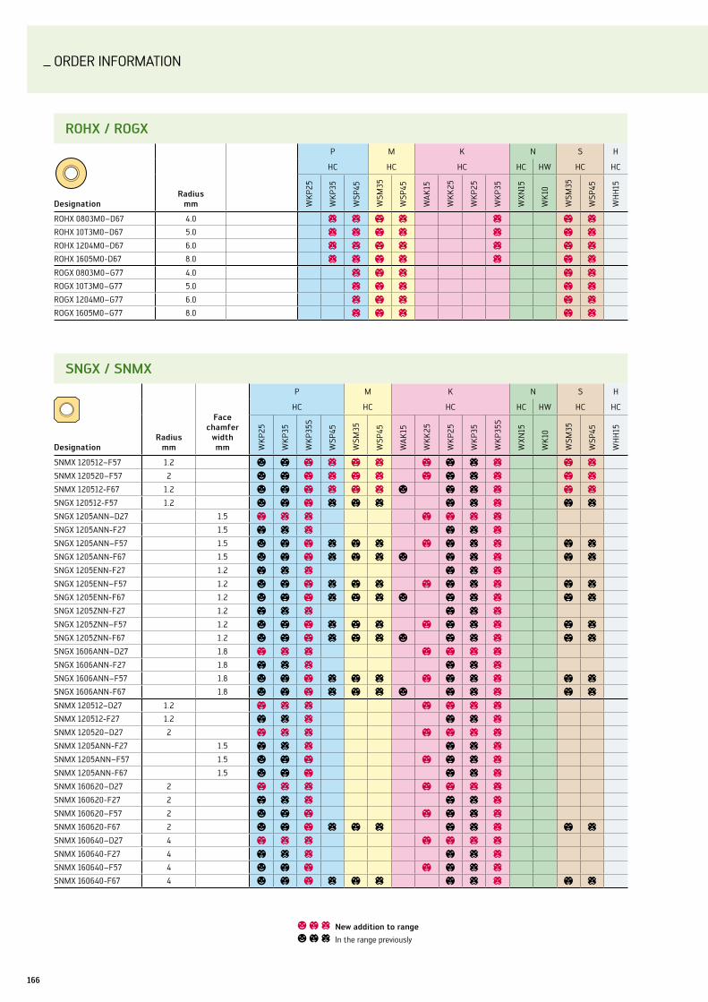
ORDER InFORMATIOn
166
rohx / rogx
Designationradius
mm
P M K n S H
HC HC HC HC HW HC HC
WK
P25
WK
P35
WSP
45
WSM
35
WSP
45
WA
K15
WK
K25
WK
P25
WK
P35
WXn
15
WK
10
WSM
35
WSP
45
WH
H15
ROHX 0803M0–D67 4.0 c c b c c b c
ROHX 10T3M0–D67 5.0 c c b c c b c
ROHX 1204M0–D67 6.0 c c b c c b c
ROHX 1605M0-D67 8.0 c c b c c b c
ROGX 0803M0–G77 4.0 c b c b c
ROGX 10T3M0–G77 5.0 c b c b c
ROGX 1204M0–G77 6.0 c b c b c
ROGX 1605M0–G77 8.0 c b c b c
a b c new addition to range
a b c In the range previously
sngx / snMx
Designationradius
mm
face chamfer
width mm
P M K n S H
HC HC HC HC HW HC HC
WK
P25
WK
P35
WK
P35S
WSP
45
WSM
35
WSP
45
WA
K15
WK
K25
WK
P25
WK
P35
WK
P35S
WXn
15
WK
10
WSM
35
WSP
45
WH
H15
SnMX 120512–F57 1.2 a b b c b c b b c c b c
SnMX 120520–F57 2 a b b c b c b b c c b c
SnMX 120512-F67 1.2 a b b c b c a b c c b c
SnGX 120512-F57 1.2 a b b c b c b c c b c
SnGX 1205Ann–D27 1.5 b c c b b c c
SnGX 1205Ann-F27 1.5 b c c b c c
SnGX 1205Ann–F57 1.5 a b b c b c b b c c b c
SnGX 1205Ann-F67 1.5 a b b c b c a b c c b c
SnGX 1205Enn-F27 1.2 b c c b c c
SnGX 1205Enn–F57 1.2 a b b c b c b b c c b c
SnGX 1205Enn-F67 1.2 a b b c b c a b c c b c
SnGX 1205Znn-F27 1.2 b c c b c c
SnGX 1205Znn–F57 1.2 a b b c b c b b c c b c
SnGX 1205Znn-F67 1.2 a b b c b c a b c c b c
SnGX 1606Ann–D27 1.8 b c c b b c c
SnGX 1606Ann-F27 1.8 b c c b c c
SnGX 1606Ann–F57 1.8 a b b c b c b b c c b c
SnGX 1606Ann-F67 1.8 a b b c b c a b c c b c
SnMX 120512–D27 1.2 b c c b b c c
SnMX 120512-F27 1.2 b c c b c c
SnMX 120520–D27 2 b c c b b c c
SnMX 1205Ann-F27 1.5 b c c b c c
SnMX 1205Ann–F57 1.5 a b b b b c c
SnMX 1205Ann-F67 1.5 a b b b c c
SnMX 160620–D27 2 b c c b b c c
SnMX 160620-F27 2 b c c b c c
SnMX 160620–F57 2 a b b b b c c
SnMX 160620-F67 2 a b b c b c b c c b c
SnMX 160640–D27 4 b c c b b c c
SnMX 160640-F27 4 b c c b c c
SnMX 160640–F57 4 a b b b b c c
SnMX 160640-F67 4 a b b c b c b c c b c

ORDER InFORMATIOn
167
TnEf
Designation
face chamfer width mm
P M K n S H
HC HC HC HC HW HC HC
WK
P25
WK
P35
WSP
45
WSM
35
WSP
45
WA
K15
WK
K25
WK
P25
WK
P35
WXn
15
WK
10
WSM
35
WSP
45
WH
H15
TnEF 1204An–D57 1.8 b c a b b c
xDgT
Designationradius
mm
P M K n S H
HC HC HC HC HW HC HC
WK
P25
WK
P35
WSP
45
WSM
35
WSP
45
WA
K15
WK
K25
WK
P25
WK
P35
WXn
15
WK
10
WSM
35
WSP
45
WXH
15
XDGT 3207200R–D57 20 b c b c b c b c
XDGT 4009250R–D57 25.0 b c b c b c b c
xngx
Designation
face chamfer width mm
P M K n S H
HC HC HC HC HW HC HC
WK
P25
WK
P35
WSP
45
WSM
35
WSP
45
WA
K15
WK
K25
WK
P25
WK
P35
WXn
15
WK
10
WSM
35
WSP
45
WH
H15
XnGX 1205Ann–F67 4.7 a a
xngx
Designation
face chamfer width mm
P M K n S H
HC HC HC HC HW HC HC
WK
P25
WK
P35
WSP
45
WSM
35
WSP
45
WA
K15
WK
K25
WK
P25
WK
P35
WXn
15
WK
10
WSM
35
WSP
45
WH
H15
XnGX 1205Enn–F67 4.5 a a
xDMT
Designationradius
mm
P M K n S H
HC HC HC HC HW HC HC
WK
P25
WK
P35
WSP
45
WSM
35
WSP
45
WA
K15
WK
K25
WK
P25
WK
P35
WXn
15
WK
10
WSM
35
WSP
45
WXH
15
XDMT 1303080R–F55 8 b c b c b c b c
XDMT 1303079R–F55 7.94 b c b c b c b c
Walter – Milling
a b c new addition to range
a b c In the range previously

Order InformationORDER InFORMATIOn
168
xngx
Designation
face chamfer width mm
P M K n S H
HC HC HC HC HW HC HC
WK
P25
WK
P35
WSP
45
WSM
35
WSP
45
WA
K15
WK
K25
WK
P25
WK
P35
WXn
15
WK
10
WSM
35
WSP
45
WH
H15
XnGX 1205Znn–F67 4.0 a a
Walter adaptor ak520
DesignationD1
mmd1
mmd2
mmx1
mmx2
mmx3
mmx4 mm kg
AK520.n63.T36.070CO 63 36 40 70 50 10 48 0.8
AK520.n63.T36.095 63 36 40 95 75 10 48 1.0
AK520.n63.T36.120 63 36 40 120 100 10 48 1.2
AK520.n63.T45.080CO 63 45 50 80 60 10 57 1.2
AK520.n63.T45.130 63 45 50 130 110 10 57 1.9
AK520.n63.T45.180 63 45 50 180 160 10 57 2.6
AK520.n80.T36.070CO 80 36 40 70 50 10 48 1.1
AK520.n80.T36.095 80 36 40 95 75 10 48 1.3
AK520.n80.T36.120 80 36 40 120 100 10 48 1.5
AK520.n80.T45.080CO 80 45 50 80 60 10 57 1.5
AK520.n80.T45.130 80 45 50 130 110 10 57 2.2
AK520.n80.T45.180 80 45 50 180 160 10 57 2.9
xnhf
Designationradius
mm
face chamfer
width mm
P M K n S H
HC HC HC HC HW HC HC
WK
P25
WK
P35
WK
P35S
WSP
45
WSM
35
WSP
45
WA
K15
WK
K25
WK
P25
WK
P35
WK
P35S
WXn
15
WK
10
WSM
35
WSP
45
WH
H15
XnHF0705Ann–D27 0.8 1.1 b c c b b c c
XnHF0705Ann-D57 0.8 1.1 b c c b b c c
XnHF0705Ann-D67 0.8 1.1 b c c a b c c
XnHF070508-D27 0.8 - b c c b b c c
XnHF070508-D57 0.8 - b c c b b c c
XnHF070508-D67 0.8 - b c c a b c c
XnHF0906Ann-D27 0.8 1.4 b c b b c
XnHF0906Ann-D57 0.8 1.4 b c b b c
XnHF0906Ann-D67 0.8 1.4 b c a b c
XnHF090612-D27 1.2 - b c b b c
XnHF090612-D57 1.2 - b c b b c
XnHF090612-D67 1.2 - b c a b c
a b c new addition to range
a b c In the range previously

ww
w.k
raas
-lac
hman
n.co
m
ToughEr. harDEr.sharPEr.
Tiger·tec®silver is the new high-performance mira-cle tool for steel and cast-iron milling from Walter. Extremely tough, extremely hard and extremely long- wearing, it improves performance by up to 100%. Featuring wear detection, a smooth cutting face and extremely sharp cutting edges, it ensures supreme surface-finish quality. let the Tiger work its magic on your production line.
The machining age is over. it’s time to Tiger.
170170
AlPHAnuMERIC InDEX
2021763 ............................92
2026763 ...........................92
2041663 ............................92
2046663 ...........................92
2121763 ............................92
2126763 ............................92
2141663 ............................93
2146663 ............................93
8041056 ............................93
8046056 ...........................93
8141056 ............................93
8146056 ............................93
390.410 .............................38
391.01 ................................38
391.02 ...............................38
391.20 ...............................38
aA3382XPl.................. 48, 49
A6181AMl ........................48
A6489DPP ................. 50, 51
A6589DPP ................. 52 ,53
A6789AMP .......................48
A6889AMP .......................48
A-DCln .............................35
A-DDun ............................35
ADGT .......................160, 161
ADKT .......................160, 161
ADMT ......................160, 161
A-DSKn ............................35
A-DTFn .............................35
A-Dvun ............................35
A-DWln ...........................35
AH3E20317 ......................111
AH3E21138 ..................... 108
AH3E21317 .....................109
AH3E23138 .................... 110
AH3E29148 .................... 108
AH3E58118 ..................... 113
AH3E58318 .................... 113
AH3E58518 .................... 113
AH3E68118 ..................... 114
AH3E82378 ....................106
AH3E85378 ....................106
AH3E93718 ..................... 107
AH3E94718 ..................... 107
AH4033217 ..................... 104
AH4034217 .....................105
AH602091 .......................123
AH602691.......................120
AH608391 ....................... 121
AH6083914 .................... 121
AH6E2311 ....................... 112
AH6E2511 .......................109
AH8E11118 ..................... 112
AK520 ............................. 168
AK600 ...............................38
AK610 ..................... 115–118
AP191 ................................32
AP192 ................................32
A-SClC .............................36
A-SDuC .............................36
A-STFC ..............................36
A-SWlC ............................36
bB4010 ................................69
B4212 ................................66
B4213 ................................66
B4214 ................................ 67
B4215 ................................68
cC8 .......................................39
C8-CP-01 ..........................39
C8-MAS-01 ......................39
C8-MAS-11 ......................39
C8-PMu-01 ......................39
C8-WDT-01 ......................39
C-ASH ...............................39
C-ASHA .............................39
CCGT .................................. 27
CCMT ...........................27, 73
C-DCln .......................33, 37
C-DCMn ............................34
C-DDJn ............................. 33
C-DDMn ...........................34
C-DDun ......................33, 37
C-DSDn ............................ 33
C-DSKn............................. 33
C-DSRn............................. 33
C-DvJn ............................. 33
C-DvMn ............................34
C-DWln ............................ 37
CnGG .................................24
CnHu ............................... 161
CnMG ................................24
CnMM ...............................24
CnMu .............................. 161
ConeFit Set Multi ......... 118
C-PCln .............................34
C-PRDC .............................34
C-PRSC .............................34
C-PSKn .............................34
C-PSRn .............................34
C-TK-02 ............................39
DDCBn .................................32
DCGT .................................28
DCKn .................................32
DCln .................................32
DCMT .................................28
DnGG ................................25
DnMG ................................25
DP2061105 .......................88
DP2061705 .......................89
DP2063105 ......................88
DP2063705 ......................89
DP2064105 ......................88
DP2064705 ......................89
DP2066105 ......................88
DP2066705 ......................89
DP2068105 ......................88
DP2068705 ......................89
DP2069105 ......................88
DP2069705 ......................89
DP2161705 .......................90
DP2166705 .......................90
DP2261705....................... 91
DP2266705 ...................... 91
DP2361705 ....................... 91
DP2366705 ...................... 91
DP2466705 ...................... 91
Dvvn .................................32
EEP2061105 .......................84
EP2061106 .......................84
EP2061115 .......................86
EP2061116 .......................86
EP2061705 .......................84
EP2061706 .......................84
EP2061745 .......................86
EP2061746 .......................86
EP2061805 .......................85
EP2061806 .......................85
EP2063105 .......................84
EP2063106 .......................84
EP2063706 .......................85
EP2063805 ......................85
EP2063806 ......................85
EP2066105 .......................84
EP2066106 .......................84
EP2066115 .......................86
EP2066116 .......................86
EP2066705.......................84
EP2066706 .......................84
EP2066745 .......................86
EP2066746 .......................86
EP2066805 ......................85
EP2066806 ......................85
EP2068105 .......................84
EP2068106 .......................84
EP2068705 .......................85
EP2068706 .......................85
EP2068805 ......................85
EP2068806 ......................85
Designation Page Designation Page Designation Page Designation Page

171171
AlPHAnuMERIC InDEX
EP2166115 ....................... 87
EP2166116 ....................... 87
EP2166705 .......................86
EP2166706 .......................86
EP2166745 ....................... 87
EP2166746 ....................... 87
EP2168705 .......................86
EP2168706 .......................86
E-SClC ..............................36
E-SDuC .............................36
E-STFC ..............................36
fF2010 ..............................159
F2339 ..............................159
F4030 ..............................152
F4031 ..............................154
F4042R ...........................158
F4045 .............................. 153
F4053.Bn........................ 157
F4080 ..............................155
F4081 ..............................155
F4138...............................156
F4153.Bn ........................ 157
F4238 ..............................156
F4253 .............................. 157
F4253.Bn ....................... 157
F4338 ..............................156
FS1384 ............................ 119
FS1385 ............................ 119
FS1476 ..............................39
FS1477 ..............................39
FS1479 ..............................39
FS2124 ............................ 119
FS2125 ............................ 119
FS2126 ............................ 119
FS2127 ............................ 119
FS2128 ............................ 119
FS2131 ..............................69
FS2132 ..............................69
FS2133 ..............................69
FS2135 ............................ 119
FS2136 ............................ 119
FS2137 ............................ 119
FS2138 ............................ 119
FS2141 ............................ 119
FS2158 ..............................39
gG1041 ................................ 37
G1042 ................................ 37
GX ...................................... 31
hH3E20317 ........................111
H3E21138 ....................... 108
H3E21317 ........................109
H3E23138 ....................... 110
H3E29148 ....................... 108
H3E58118 ....................... 113
H3E58318 ....................... 113
H3E58518 ....................... 113
H3E68118 ....................... 114
H3E82378 .......................106
H3E85378 .......................106
H3E93718 ....................... 107
H3E94718 ....................... 107
H4033217 ....................... 104
H4034217 .......................105
H4036217 ....................... 104
H4038217 .......................105
H5075011 .........................94
H5075018 .........................94
H5083008 .........................94
H5087006 .........................94
H602091 .........................122
H602691 .........................120
H608391 ......................... 121
H6083914 ....................... 121
H6E2311 .......................... 112
H6E2511 .........................109
H8E11118 ........................ 112
Designation Page Designation Page Designation Page Designation Page
kK600 ..................................38
llnGX ...............................162
lnHu ...............................162
lnHX ...............................162
lnMu ..............................162
lnMX ..............................162
nnTS .................................... 31
oODHT ............................... 163
ODHW.............................. 163
ODMT .............................. 163
ODMW ............................. 163
PP23696 ........................... 163
P26379 ............................ 163
P3201 ..................... 164, 165
P3204 ..................... 164, 165
P45420 ...........................165
P4840 ................................ 70
P4841 ................................ 70
P6003 ..........................71, 72
P6004 ..........................71, 72
P6500 ................................ 73
P8001 .............................. 164
PCln .................................32
PRDC .................................32
PRGC .................................32
PSDn .................................32
PTGn .................................32
rRCGT ..................................28
RCMT .................................28
RCMX.................................28
RDHW ..............................165
RDHX ...............................165
ROGX ...............................166
ROHX ...............................166
sSCGT ..................................29
SCMT .................................29
SnGX ...............................166
SnHX ...............................166
SnMG ................................26
SnMM ...............................26
SnMX ..............................166
TTCGT ..................................29
TCMT .................................29
TnEF ................................ 167
TnMG ................................26
TnMM ...............................26
vvBMT .................................30
vCGT ..................................30
vCMT .................................30
vnGG .................................26
vnMG ................................26
WWnMG ............................... 27
xXDGT ............................... 167
XDMT ............................... 167
XnGX .......................167, 168
XnHF ............................... 168

_ WAlTER WORlDWIDE
NORTH AMERICA
Walter usa, inc.Waukesha, WI, uSA
TDM systems inc.Schaumburg, Il, uSA
Walter Tools s.a. de c.v.Tlalnepantla, Mexico
Walter [email protected]
SOUTH AMERICA
Walter do brasil ltda.Sorocaba, Brazil
Walter argentina s.a.Capital Federal, Argentina
ASIA PACIFIC REgION
Walter Wuxi co. ltd.Wuxi, China
Walter ag singapore Pte. ltd.Singapore
Walter korea ltd.Korea
Walter Tools india Pvt. ltd.Pune, India
Walter Tooling japan kknagoya, Japan
Walter (Thailand) co. ltd.Bangkok, Thailand
Walter Malaysia sdn. bhd.Selangor, Malaysia
Walter australia Pty. ltd.victoria, Australia
EUROPE
Walter Deutschland gmbh Frankfurt, Germany
Werner schmitt PkD-Werkzeug gmbhniefern-Öschelbronn, Germany
TDM systems gmbhTübingen, Germany
Walter (schweiz) agSolothurn, Switzerland
Walter benelux n.v./s.a.Zaventem, Belgium
Walter gb ltd.Bromsgrove, Great Britain
Walter italia s.r.l.Fino Mornasco (CO), Italy
Walter franceSoultz-sous-Forêts, France
Walter Tools iberica s.a.u.El Prat de llobregat, Spain
Walter norden abHalmstad, Sweden
Walter cZ spol.sr.o.Kurim, Czech Republic
Walter Polska sp. z o.o.Warsaw, Poland
Walter hungária kft.Budapest, Hungary
Walter austria gmbhvienna, Austria
sc Montanwerke Walter srlTimisoara, Romania
Montanwerke Walter gmbh - Podruz̆nica Trgovina slovenijaMiklavz̆na Dravskem Polju, Slovenia
Walter llcSt Petersburg, Russia
Walter slowakei, o.z.nitra, Slovakia
Walter kesici Takimlar sanayi ve Ticaret limited sirketi Istanbul, Turkey
HEADQUARTERS
Walter agTübingen, Germany
how to find us.
www.walter-tools.com


Walter AG
Derendinger Straße 53, 72072 Tübingen Postfach 2049, 72010 Tübingen Deutschland www.walter-tools.com
Walter GB LTD. Bromsgrove, England +44 (1527) 839 450, [email protected] Walter Kesici Takimlar Sanayi ve Ticaret Limited Sirketi Istanbul, Turkey +90 (216) 528 1900 Pbx, [email protected] Walter Wuxi Co. Ltd. Wuxi, Jiangsu, P.R. China +86 (510) 8241 9399, [email protected] Walter AG Singapore Pte. Ltd. +65 6773 6180, [email protected] Walter Korea Ltd. Ansan, Kyungki-do, Korea +82 (31) 3646 100, [email protected] Walter Tools India Pvt. Ltd. Pune, India +91 (20) 2714 5028, [email protected] Walter (Thailand) Co., Ltd. Bangkok, Thailand +66 (2) 6811 305, [email protected] Walter Malaysia Sdn. Bhd. Selangor D.E., Malaysia +60 (3) 8023 7748, [email protected] Walter Australia Pty. Ltd. Melbourne, Australia +61 (3) 8793 1000, [email protected] Walter New Zealand Ltd. Christchurch, New Zealand +61 (3) 8793 1000, [email protected] Walter Tooling Japan K.K. Nagoya, Japan +81 (52) 723 5800, [email protected] Walter USA, Inc. Waukesha (WI), USA +1 800-945-5554, [email protected] TDM Systems Inc. Schaumburg (IL), USA +1 (847) 605 1269, [email protected] Walter Tools S.A. de C.V. Saltillo Coahuila, Mexico +52 (55) 5365-6895, [email protected] Walter Canada [email protected]
Prin
ted
in G
erm
any
591
3788
(04/
2010
) EN