innovating the future of fttx and hfc networks
TRANSCRIPT

Broadband networks case studiesInnovating the future of FTTx and HFC networks

A customer’s network planner
“ CommScope knocked the
ball out of the park. Our
situation is unique and
they took the time to listen
and learn about us. That
was crucial to the success
of this project.”

Introduction . . . . . . . . . . . . . . . . . . . . . . . . . . . . . . . . . . . . . . . . . . 4
01 – Innovation on a paper napkin . . . . . . . . . . . . . . . . . . . . 5
02 – Broadband for everyone: A rural case study . . . . . . 10
03 – National utility goes broadband . . . . . . . . . . . . . . . . . 15
04 – Fiber protection in a small box . . . . . . . . . . . . . . . . . . . 20
05 – Fiber optimized for the future. . . . . . . . . . . . . . . . . . . . 25
06 – Rural company, urban footprint . . . . . . . . . . . . . . . . . . 30
07 – Building fiber expertise . . . . . . . . . . . . . . . . . . . . . . . . . . 35
08 – Open and interoperable . . . . . . . . . . . . . . . . . . . . . . . . . 40
09 – An enclosure that goes the extra mile . . . . . . . . . . . . 45
Broadband network case studies
4
Back to Contents =Introduction
A lot of solution providers in the telecom industry
focus on a portion of what is needed for a successful
broadband network and HFC rollout, but few can offer
a true end-to-end solution. At CommScope we are
committed to providing our customers the support they
need to be successful. Our solutions are built on 40 years’
experience solving customer needs from all over the globe
and working side-by-side on their broadband rollouts
to ensure maximum efficiency and performance. Our
customers rely on us to be a trusted partner, working
with them to create the best broadband and HFC
network solution.
For me, this eBook is a small list of the many ways we
have helped solve customer’s challenges with their
broadband rollouts illustrating how we helped standardize
one cable operator’s network after several mergers, or
trained fiber optic technicians on an ambitious broadband
rollout. Overcoming the challenges of yesterday has given
us the knowledge and experience to tackle what lies
ahead. Everything we do is to help our customers—our
customers matter.
CommScope’s culture of innovation and problem-solving
is how our world-class engineers bring powerful ideas to
market. We couldn’t do any of this without customers’
input and requests. Their networks are constantly changing,
and they can trust CommScope to know what’s next.
These pages demonstrate just that. We can be part of
building every aspect of a network with end-to-end
solutions from the central office to inside customer
premises. We listen to customers’ challenges and can
quickly adapt. Our team can train people who have never
built a network and partner with the customers moving
from a coaxial or copper network to a full broadband
network. Our solutions are built to withstand rugged
environments in any part of the world. This is what we do.
CommScope is proud to help build, design and
deploy high-quality networks and develop long-lasting
relationships. This eBook is dedicated to our esteemed
customers who made these success stories possible. Thank
you for showing the world what we can do together.
Erik Gronvall VP, Strategy and Market Development at CommScope
Case Study
01 - Innovation on a paper napkin

6
Back to Contents = 01 - Innovation on a paper napkin
Thinking and designing outside the boxLocated in the APAC Region, this service
provider is deploying FTTH in urban
and suburban areas across the country.
Reusing manholes, conduits, and
other aspects of the existing telephony
infrastructure would help speed up the
deployment and keep costs under control.
The challenge: construction costs and delays
It started with a solid plan—upgrade key
parts of the underground infrastructure to
make room for the new fiber equipment.
As construction work began, it became
apparent that the aging infrastructure
was in worse condition than expected.
Prolonged and unbudgeted civil works
would be required.
So, back to the drawing board
Was it possible to design a new, significantly
smaller fiber terminal that fit into the
existing underground space in order to
avoid construction?
Was it possible to design a new, significantly smaller fiber terminal that fit into the existing hand holes in order to avoid construction?

7
Back to Contents = 01 - Innovation on a paper napkin
“You’ve got to roll with the punches—sometimes you just have to work with what you’ve got,” said a project engineer. That meant designing a fiber-optic terminal with the same functionality as the MST, the CommScope product originally specified, but one with a much smaller footprint. Given that the form factor of the MST was already optimized to be compact, this was not a simple task.
The initial concept for a new terminal
Deconstructing the functional elements
Multi-fiber feed drops
Brainstorming … in a restaurant
“Our first idea came to us at a dinner
winding down after work. We literally
sketched it on the back of a paper napkin,”
said a CommScope R&D engineer. “It wasn’t
the design we ended up with, but there
were a couple of key ideas in there that
made it into the final product.”
Tear it down, then build it back up
The R&D team then took a deconstructionist
process in stripping the fiber terminal
down to its core functional elements, then
regrouping those elements into different
configurations for different designs.
Ultimately, the final design resulted from
this approach.
When space is at a premium

8
Back to Contents = 01 - Innovation on a paper napkin
The space/footprint constraint was solved
by extending the connectors outside
the terminal, literally an out-of-the-
box solution. The terminal became less
compact but far more flexible, and hence
easier to fit into congested spaces. The
cables were staggered in length, thus
allowing installers easier access to perform
installation and maintenance work.
It took six months from the first
design on a paper napkin to a working
prototype used for initial testing by the
service provider.
The final design: Flexible service terminal
six monthsconcept design innovation
The final design

9
Back to Contents = 01 - Innovation on a paper napkin
Summary
With this new product, specifically designed
for space-constrained environments, the
service provider was able to avoid tens of
millions of dollars in unforeseen construction
costs and months of delay in the network
deployment.
The choice of products can sometimes have
a large impact on overall deployment costs
and schedules.
White paper >>
Fiber access terminals >>
FOSC solution >>
TENIO splice closure >>
Rapid mini-RDT and Rapid faceplate >>
Web page >>
Blog >>
LEARN MORE
Products in this network
Plan for the right product…but be prepared to adapt when the situation changes.

Case Study
02 - Broadband for everyone: A rural case study

Back to Contents =
11
02 - Broadband for everyone: A rural case study
The ever-increasing use of connected devices
raises consumer demand for speed and
bandwidth. These expectations for seamless
connections coupled with the speed of data,
doesn’t stop at the city limits. Service providers
and MSOs are quickly working to extend
broadband into the rural and exurban areas.
The Challenge: Extending the reach of broadband
Bringing broadband service to rural and
underserved exurban areas can pose unique
challenges to providers. Deployments must
cover great distances to reach just a few homes.
Rural areas have higher costs per home passed,
and require high subscriber take rates to make
fiber deployments economically possible.
Providers must invest heavily in equipment
Broadband for everyone

Back to Contents =
12
02 - Broadband for everyone: A rural case study
and labor, so solutions that can reduce
expenditures in either of those key categories
can make the difference between economic
success or failure.
When extending to rural installations,
network architecture is a crucial decision for
providers. These deployments can cover great
distances of sparsely-populated terrain, with
just three or four homes per kilometer. Land
can be mountainous, forested, or desert, with
little existing infrastructure. Providers need
solutions with design simplicity, to keep labor
and equipment costs as low as possible.
One option, employed by service provider,
to create or expand rural fiber-to-the-home
(FTTH) networks economically is using a
TAP architecture.
Fiber-optic TAPs—a nontraditional approach
In a TAP FTTH network architecture, a fiber
cable is deployed throughout a service area,
and fiber-optic TAPs (Terminal Access Points)
divert optical signals to subscribers. It’s a simple
process. The cable is opened and one of the
fibers inside is carefully cut. A fiber-optic TAP
is spliced into the line, which siphons off a
portion of the signal for a subscriber. The TAP
allows the signal to continue down the line to
the next home or business, where the process
is repeated. Multiple TAPs can be spliced into
the line until the signal is exhausted—usually
at 32 subscribers. At this point another fiber
in the cable is cut, and the process continues.
Key benefits:
• Equipment savings• Labor savings • More efficient to
deploy • Easier to maintain • Easy future expansion
Splitter cabinet
Fiber feeder
HECO
MNONUONT
1:32
Fiber feeder
HECO Tap Tap TapTap
MNONUONT
MNONUONT
MNONUONT
MNONUONT
A traditional, centralized, FTTH network architecture (top) compared to a distributed TAP network architecture (below)
TAP ARCHITECTURE

Back to Contents =
13
02 - Broadband for everyone: A rural case study
A TAP network design is quite different from
the design of a traditional “centralized”
FTTH network, which typically uses splitters
installed in a cabinet configuration to
distribute data to subscribers. In this splitter-
based architecture, a fiber-optic feeder line
runs from the central office or head-end
location to a cabinet in the street or service
area. The feeder line terminates on an optical
splitter in the cabinet, which distributes the
signal to subscribers with additional fibers.
This hub-and-spoke design gives providers
great flexibility, as the cabinets allow easy
management of both fiber connections
and central office equipment, and can
also be used in proximity to remote central
office equipment.
Equipment and cable savings
The biggest difference between TAP network
and splitter-based architectures is in their
respective cabling requirements. For a
deployment serving 256 subscribers, the
minimum number of fibers required in the
splitter-based architecture is 256. These 256
fibers run in several smaller cables from the
equipment cabinet. The cabinet is necessary
to house the eight 1x32 splitter components,
which route optical signals to subscribers,
as well as permit fiber access for ongoing
maintenance. For many rural deployments,
splitter-based architecture is considerably
more expensive, as it requires the use of much
more fiber cable and distribution equipment.
Faster installations at lower cost with TAP network architecture.
• Fewer fiber cables required • Design simplicity—one type of small fiber count
cable can be used • Less splicing required, saving skilled labor • No need for complicated splice maps• Large equipment savings—distribution cabinets
and splitters generally not needed
In comparison, for a 256-subscriber
deployment, TAP architecture needs a
minimum of eight fibers. Two four-fiber
cables are run directly into the served area,
without the need for a cabinet to house
splitters and connections. Cable savings
would depend upon the length of the runs
to the actual drop points; but, since four-
fiber cable costs much less than 72-fiber
cable, savings could easily run to thousands
of dollars. With TAP architecture, providers

Back to Contents =
14
02 - Broadband for everyone: A rural case study
have seen large reductions in the number of
optical fibers used in a deployment—some
as large as 87 percent. TAP architecture
also avoids the need for an equipment
cabinet, splitters, mounting pad, and cabinet
installation labor.
Planning for future expansion
Some operators believe that, compared
to splitter architecture, TAP architecture
networks are difficult to expand. While it’s
true, TAP systems are often designed with
minimal fiber us to save as much up-front
cost as possible. Designers can use a 1:2 split
at launch to increase optic use efficiency; if
expansion is required later, this 1:2 split can
be removed to add capacity, and additional
fiber-optic TAPs added to change to a higher
port count. And, in another expansion
strategy, many operators purchase dark fibers
along with the initial four-fiber cables, as the
economics are best with a full buffer tube of
12 fibers. The cable size doesn’t change, and
the additional dark fibers provide the highest
utility of all solutions, with each fiber good for
another 32 homes.
Summary
While there are both financial and
topographical challenges to deploying
broadband in rural areas, using TAP network
architecture is optimal choice to help
overcome them. A major benefit of this
design is the significant reduction in fiber
required to serve a rural area. With the long
distances typically involved in rural FTTH
deployments, this reduction in fiber count can
dramatically reduce up-front network costs
and allow providers to serve areas where
deploying a traditional fiber network would
have been cost-prohibitive.
White paper >>
Blog >>
LEARN MORE
Optical TAP solutions brochure >>
Products in this network

Case Study
03 - National utility goes broadband

Back to Contents = 03 - National utility goes broadband
Recognizing that the digital economy would be a key pillar of the country’s future growth and competitiveness on the world stage, this European electrical utility decided to bring high-speed internet access to homes and businesses across the country. The utility would build and own an open-access FTTH infrastructure and lease it to partners—who, in turn, would offer retail internet and other services to subscribers.
The challenge: Cost overruns
The first phase of deployment covered
approximately half a million premises.
The utility had an extensive electrical grid
infrastructure, rights of way, experience
in outside plant deployments, and even
a fiber backbone supporting leased
fiber services. However, FTTH was a
new architecture for them. As deployment
started, the utility began to see cost
spikes. How did they deal with the costs
and bring the project back on track?
16
Internet as a utility
How did they deal with the costs and bring the project back on track?

Back to Contents =
17
03 - National utility goes broadband
Redesigning the network
“There are some unique challenges in
building FTTH on top of a live electrical
distribution system,” says the CommScope
engineer. “The utility had to minimize
service disruption. Installer safety was
of paramount concern when working in
close proximity to high-voltage equipment.
And, on top of all this, the grid maps were
sometimes out of date.” The unexpected
scope of these issues pushed installation
costs well above budgetary estimates.
Rainy days
Another factor was the wet weather.
The amount of rainfall and the propensity
for flooding meant the equipment had to
be well sealed to provide water-resistant
or waterproof protection.
IP ratings represented by combining the first and second digits of the following columns. See examples below.
1st digit - SOLID 2nd digit - LIQUID 1st digit - SOLID 2nd digit - LIQUID
0 0
2 2
3 3
4 4
5 5
Example:
6 6
7 7
8
9
Protecting the network against water
2.5mm
1.5mm
+
IP 6 5
No protection No protection
Protection against asolid object greaterthan 50mm, such as a hand
Protection against asolid object greaterthan 12.5 mm, such as a finger
Protection against asolid object greaterthan 2.5 mm, such as a wire
Protection against asolid object greaterthan 1.5 mm, such as a thin strap
Protected againstwater drops
Protected against water drops at a15 degree angle
Protected against water spray at a60 degree angle
Protected against water splashing from any angle
Dust protected.Prevents ingress ofdust sufficient tocause harm
Dust tight.No ingress of dust
Protected againstwater jets fromany angle
Protected against water jets from any angle
Dust tight. No ingressof dust
Protected againstpowerful water jetsand heavy seas
Protected against theeffects of temporary submersion in water(30 minutes at 3 feet)
Protected against theeffects of permanentsubmersion in water(up to 13 feet)
“In situations like these, there is rarely a one-
size-fits-all approach,” said the CommScope
account manager. “What was needed was a
set of economical solutions that fit well with
their existing grid infrastructure. The initial
network was designed for maximum flexibility
and growth… and this comes at a price.
We conducted detailed field surveys and,
once armed with the data, we could then
optimize the network architecture and
product selection.”
Protecting the network against water

Back to Contents =
18
03 - National utility goes broadband
Reducing installation costs
“We reduced the number of the smaller
cabinets by building a centralized
topology that places splitters 1:32 in
a central location. Initially these hubs
with splitters were cabinets but, due
to the civil works and installation costs
involved, this was not an ideal solution.
An alternative way to meet the goals
of the network at lower cost was
moving splitters into splice closures with
cold sealings, easy access and good
flexibility for growth, reducing labor
costs significantly, reducing labor costs
significantly by reducing training and
installation time. Being environmentally
hardened, preconnectorized and not
requiring open access, even on day one,
they also provide excellent protection
against the elements.”
When unforeseen costs spiral out of control, a trusted partner can get you back on track.

Back to Contents =
19
03 - National utility goes broadband
Summary
A network redesign, an optimized set of products, and a focus on labor
savings helped put the project back on budget. The utility’s network
planner said, “CommScope showed they were true partners. We had
worked with them on our leased fiber network in the past, so it was natural
to bring them onboard for FTTH. They were quick and responsive, and their
global experience provided a welcome perspective.”
Web page >>
FACT ODF >>
FiberGuide optical raceway >>
FDH (Fiber distribution hub) >>
FOSC (Fiber optic splice closure) >>
TENIO splice closure >>
Hardened connectivity >>
Mini-OTE terminal >>
Premises box >>
Video >>
Blog >>
LEARN MORE
Products in this network
“ They were quick and responsive, and their global experience provided a welcome perspective.”

Case Study
04 - Fiber protection in a small box

04 - Fiber protection in a small box Back to Contents =
21
The Hanghuang high-speed rail line is 265km long, built at a
cost of RMB 36.55 billion. The route passes seven 5A-level scenic
spots, making the line one of the most beautiful in China.
Just as the train requires reliable access to rail signals along every
meter of the route, passengers require mobile connectivity to
enjoy a positive user experience. In order to assure both train
and passengers have that reliable, high-speed network access,
the Hanghuang railway looked to CommScope for the fiber
networking solutions needed to operate safely and comfortably.
Fiber protection in a small box

22
04 - Fiber protection in a small box Back to Contents =
The customer’s challenge
When passengers pass through the mountains
and enjoy the beautiful scenery outside
their windows, they likely never consider
the difficulty of high-speed rail construction,
nor the complicated geological conditions
that make the Hanghuang line particularly
challenging. Because the route passes
through many unfavorable geological areas—
water-rich fracture areas and extremely high
ground stress zones, multiple tunnels and
bridges—it is particularly important to ensure
stable and reliable cable splice protection
when laying optical fiber to ensure the signal
connection of optical fiber repeaters along the
railway meet long-term development needs.
Unlike the optical fiber network architecture
and construction environment of traditional
telecom operators, this application requires
independent cable slots, signal control cables
and communication cables along the route.
However, due to the limited internal space of
cable slots, optical fibers cannot be rolled up
at the splice point (as it would be in a typical
urban deployment) and the cap type cable
splice closures cannot be used. Instead, a
linear cable splice box must be used.
In addition to the technical challenges,
planning challenges also came into play. The
complexity of the terrain along the railway,
the construction’s initial, early-stage difficulties
and the tight deadline for its completion all
meant that the construction team needed to
complete cable laying and welding for the
three participating wireless operators quickly
and efficiently, in order to carry out the joint
debugging test on schedule. This required the
ability to quickly and securely manage fiber
splicing along the line.

23
04 - Fiber protection in a small box Back to Contents =
The CommScope solution
The communications operator serving
the Hanghuang high-speed rail chose
CommScope’s linear gel-sealed splice closures
for this critical external network. The linear
gel-sealed splice closure uses a supple sealing
gel that can be formed to shape with minimal
pressure and retain memory of that shape.
When sealed, the gel distributes force evenly
and fills the entire chamber space for a
superlative seal.
Due to the high cost and difficulty of
maintenance, the solution had to provide
long-term stability and reliability in
operation—any problems would have
severe safety implications for train operation
as well as passenger experiences. Therefore,
the splice closure solution had to work
correctly from the outset and provide many
years of reliable service.
Traditional horseshoe gel closures were
complex and difficult to install. The gel
is hard and require bolts to seal the
closure, which takes a great deal of
time. Furthermore, any maintenance
of the closures required the removal
and replacement of sealing gaskets,
which introduced a greater risk of water
infiltration and network degradation.
These advantages effectively ensure the
long-term stability of the optical fiber,
fully satisfying the unique and demanding
stability requirements of the locomotive
signal transmission.

24
04 - Fiber protection in a small box Back to Contents =
The results
CommScope’s linear gel-sealed splice
closures significantly shortened installation
time and improved the efficiency of regular
maintenance processes.
The customer’s analysis revealed that
installation time was reduced by 15 percent,
and maintenance that involved opening and
resealing the closures was reduced by an
amazing 30 percent.
While comprising only a small percentage
of overall construction costs, CommScope’s
linear gel-sealed splice closures provided an
extremely valuable level of reliability in fiber
nodes carrying the rail signal control as well
as passenger connectivity.
Due to its compact size, quality construction,
favorable CapEx and OpEx characteristics,
ease of installation and simplicity of
maintenance, CommScope’s solution proved
to be an ideal match for the Hanghuang
high-speed rail line—and indeed any rail
transit application.
Web page >>
FOSC brochure >>
Blog >>
LEARN MORE
Products in this network
+ CapEx
+ OpEx

Case Study
05 - Fiber optimized for the future

26
Back to Contents =05 - Fiber optimized for the future
This telecom operator provides wired and wireless network and infrastructure services. Its investment in fiber optics and a high-speed, high-bandwidth, full-fiber network led to the need for a comprehensive fiber management solution.
End-to-end solutionsWe offer a comprehensive fiber portfolio, spanning the customer premises, MDU, fiber access network, through to central office and head-end equipment.
Fast forward to the future

27
Back to Contents =05 - Fiber optimized for the future
Space raceOver time, the operator purchased off-the-shelf cable management
products that couldn’t keep up with future growth. Limited access
space and lack of cable management features affected the network’s
flexibility and reliability. An increasing number of optical fiber ports
and lack of optical cable management resulted in cluttered cables
and low usage rates for device ports.
Clean and leanCommScope’s Next Generation Frame solution was the ideal choice
to upgrade this infrastructure. Its modular design features a unified
rack structure that has abundant trough space, minimizing fiber
pileup and congestion. Accessing cables and connectors is easy
with this horizontal platform. The frame also makes it easy for the
operator to move or add equipment.
Download our product catalog to learn more about our frame solutions >>
How would this telecom operator meet the demands of a full fiber network?

28
Back to Contents =05 - Fiber optimized for the future
Seeing successThe operator faced a tight deadline to find a reliable and secure solution
due to the fast-approaching BRICS Summit, an event that required
stable, secure communication. A CommScope partner quickly surveyed
15 central equipment rooms where the frame solution would be
installed, identifying exact connector lengths for each site. CommScope
helped fulfill the orders, meeting the operator’s schedule.
The operator chose a 96-core module with an option to upgrade
to 144-core, depending on future needs. The equipment rack can
expand up to 40 percent using CommScope’s Next Generation Frame.
Components such as splitters, couplers and wavelength division
multiplexers are also available to help the operator enhance the usage
rate for fiber resources.
Small changes in your network can make a big difference your in efficiency.

29
Back to Contents =05 - Fiber optimized for the future
The right fiber solutions are scalable and grow with you.
Reliability on demandTelecom operators need systems
and equipment they can count on
for optimal performance, uptime
and growth flexibility. CommScope’s
plug-and-play solutions easily
accommodate frequent adds
and changes to equipment while
promoting speed and efficiency.
Web page >>
Product brochure >>
White paper >>
Video >>
LEARN MORE
Challenges of an evolving network
Complex fiber migration & management
Rising bandwidth demands
Increasing pressure to ensure reliability
Cost containment throughout the network

Case Study
06 - Rural company, urban footprint

Back to Contents =
31
06 - Rural company, urban footprint
Founded over 50 years ago, today this small,
local broadband service provider serves several
thousand customers. Rural broadband is
particularly challenging, as low population
density means higher deployment costs. “The
demand has always been here,” said a telco
manager working for the client. “But service
providers must be willing to invest the time and
money to deliver the service. Our willingness
to do that has meant higher levels of customer
loyalty, and it’s allowed us to grow.”
The challenge: Competing against the Goliaths
Over the years, this provider has attempted to
expand its service area to more profitable urban
areas. But a small company going head-to-
head against much larger providers us was not
an easy proposition. “If we went into a new
market, the ‘big boys’ would just swoop in to
take all the accounts. It’s difficult to compete,”
said the telco manager.
How to compete and differentiate against much larger providers with deeper pockets?
Rural broadband, urban footprint

Back to Contents =
32
06 - Rural company, urban footprint
“Genius” layout
To find a new way to compete with the larger
service providers, the telco created a specialized
broadband business. “They wanted to do a
test case with our fiber indexing solution,” said
a CommScope account manager, “to see if it
would allow faster deployments with less fiber.”
Fiber indexing is the shifting of a fiber’s position
from one multifiber connector to another, within
each terminal (see image to the right).
The results were encouraging: the telco called
the no-splice, connectorized technology “genius”
for its layout, loss calculation, and speed of
deployment.
In the deployment that followed, the telco
installed aerial distribution hubs that allowed fiber
cable to cascade down streets on pole lines. The
pilot phase of this project involved six locations,
serving 150 homes. Fiber indexing terminals were
placed on telephone poles and linked by multi-
fiber cables in a linear, cascaded fashion.
Fiber 1 1 2 2 3 3 4 4 5 5 6 6 7 7 8 8 9 9 10 10 11 11 12 12
Reverse feed
Forward feed
Single-fiber connectors
Single-fiber connector
12-fiber cable stub
12-fiber connector
12-fiber connector
The “cookie-cutter”configuration for a
building block
The process begins with a 12-fiber cable from the fiber distribution hub (FDH) entering the first index terminal.
Inside the terminal, the fibers divide and the signal from the fiber in the first position is routed to a 1:4 or 1:8 splitter for servicing local customers.
The remaining fibers are “indexed”—advanced one position in the order—then combined using a 12-fiber HFMOC.
The exiting 12-fiber hardened cable connects to the next terminal where the indexing process is repeated.
1
How fiber indexing works
2 3 4

Back to Contents =
33
06 - Rural company, urban footprint
50 percent fiber cable savings
The total scope of the project was
3,000 homes passed, and the savings
in fiber cable was considerable.
“We’re so small, we can’t inventory as
much material as we’d like,” said the
telco manager. “CommScope’s fiber
indexing technology let us connect
these homes with less than half the
usual amount of cable. That’s been a
huge help.”
CONNECTION OPTIONSNETWORK ARCHITECTURE
Fiberspicing
Star Linear Hardened connectors
50% lesscable usage
35 minutes
5 minutes
Use of pre-terminated connectorseliminates splicing, thus reducing the total time of connecting a customer to the fiber network
Fiber indexing technology reduces the amount of cable used to less than half of the amount used in a star topology network
Linear topology of terminals led to:

Back to Contents =
34
06 - Rural company, urban footprint
No going back
“It’s worked so well, I don’t think we’d
ever go back to the traditional methods,”
said the telco manager. Fiber indexing has
allowed the small firm to compete with
much larger companies because they can
deploy faster, with less labor, using less
material. “We can focus on giving our
customers better service, and hook them up
faster than ever before. Initial construction
now takes three weeks instead of nine, and,
instead of four install calls a day, we can
schedule as many as 10. I tell you, this has
been a game-changer for us.”
The right technology can create a competitive edge.
White paper >>
Fiber access terminals >>
Hardened connectors >>
Fiber distribution hub >>
Web page >>
Blog >>
LEARN MORE
Products in this network

Case Study
07 - Building fiber expertise

Back to Contents =
36
07 - Building fiber expertise Back to Contents =
This state-owned incumbent telecom operator
began as a postal and telegraph service more than
125 years ago. Today, they serve millions of citizens
with telephony, mobile, and broadband services.
Recognizing the importance of high-speed internet
to economic growth and global competitiveness,
the nation’s president supported an ambitious
FTTH program to cover the entire country.
The challenge: A lack of fiber knowledge
The initial phases—research, planning, standards
setting, network design, and vendor selection—
were completed by a relatively small group of
experts, but large teams of fiber-optic technicians
and installers would be needed for the deployment.
Since fiber expertise was limited to a small number
of optical backbone specialists, and the telco did
not even have a program to train technicians, this
would prove to be their biggest challenge.
How did this telco develop an accelerated program to train field installers?
An ambitious plan

Back to Contents =
37
07 - Building fiber expertise Back to Contents =
Knowledge transfer
Before the actual training began, townhall-style meetings were
held. Putting a human face to this new technology was important,
so local CommScope engineers who had worked on deployments
in other countries shared their experiences. A train-the-trainers
program was developed together with the local university;
installation manuals and training materials were supplied in the local
language. CommScope engineers supervised the initial installations,
sharing practical advice and tips as well as ensuring that high
standards and industry best practices were adopted.
It’s all about your people
“Many of the older technicians, who’d worked with copper for
decades, felt threatened by the new fiber technology,” said the
telco’s training manager. “Working with fiber requires higher skill
levels than working with copper. They thought they were obsolete.
There was resistance at first, but drawing the parallels between
fiber and copper allowed them to tap into their past experience and
helped them feel more comfortable. The hands-on product training
went a long way, and, ultimately, our technicians embraced the
new technology. It just takes time to change people’s mindsets.”
500 CommScope trained trainers and technicians…
went on to train…
CommScope’s train the trainers program
3000 installation technicians

Back to Contents =
38
07 - Building fiber expertise Back to Contents =
Fiber stripping and cleaning
Fiber cleaving Fibers are joined in a fusion splicer
The display shows the quality of the
fusion splice
Spliced fibers and protective sleeve
(SMOUV)
Fiber fusion splicing in five steps
Fusion splices are used to join two pieces of
fiber-optic cable. Two strands of filament, each
about 125 microns in diameter, are welded
together so the laser light signals pass through
the cable without interference. This complex
process demands a high degree of precision.
A human hair and a fiber strand magnified 25,400%
Fiber strand diameter
Human hair diameter
1 2 3 4 5

Back to Contents =
39
07 - Building fiber expertise Back to Contents =
Products that don’t need special tools
Working with fiber generally requires
special cable and splicing tools. But the
telecom operator was able to deal with
the shortage of experienced technicians by
choosing products that could be installed by
technicians with limited experience and a
basic set of mechanical tools. One example
is the FOSC 450 fiber-optic splice closure.
Its cold seal gel technology does not require
any electrical tools.
World leader in homes connected
Deployments began in the big cities, then
moved out into the rural areas. CommScope
directly trained more than 500 technicians for
the project, who went on to train more than
3,000 installers. In deploying this network,
the state-owned incumbent telco has
achieved something remarkable: the country
now has the highest FTTH penetration rate
in the region, and it is widely recognized that
their ICT (Information and Communications
Technology) strategy has had a real impact
on the country’s economy and future
development.
Invest in training your staff. Outside plant
fiber will provide service for decades to come,
so protect your investment by doing the job
right the first time.
Web page >>
Network application >>
Performance testing >>
Material science >>
Field training >>
Video >>
CommScope Infrastructure Academy >>
LEARN MORE
CommScope Capabilities
”This new technology changed every-thing. Our installations could be done by contractors who’d had just two hours of training. And they didn’t need splicing equipment. It’s made us much more competitive.“

Case Study
08 - Open and interoperable

Back to Contents =
41
08 - Open and interoperable
Connecting all the piecesThe country was ready for ultra-high-speed
internet: this large, incumbent mobile and
fixed-line service provider decided to introduce
fiber-to-the-home (FTTH) to 40 cities and begin
migrating their fiber-optic cable access network
from copper-based xDSL. Smaller local players
may have been first to market with FTTH, but
the incumbent’s dominant installed base and
extensive coverage put them in pole position.
The challenge: Will the pieces fit together?
How did they build a standards-compliant,
open and interoperable network?
Local guidelines called for a mix of national and
international vendors for the FTTH infrastructure.
To ensure multi-vendor interoperability, the
telco established compliance to standards
as a fundamental principle. Similar to other
incumbents around the world, this service
provider had extensive experience with copper
access and fiber backbone networks—but not
with FTTH network standards.

Back to Contents =
42
08 - Open and interoperable
IFDB floor box
StandardsUpgrading network infrastructure brings unique challenges
A multi-vendor network must be flexible and
upgradeable to new products as the technology
evolves. “The scale of the national deployment
meant that fiber interoperability had to be built
up as an ongoing process. We worked with our
customer to create internal standards guidelines
that helped to streamline their bidding process,”
said a CommScope account manager. Once
the network design process got underway, the
local team began fiber technology training for
installers and technicians.
MDU field trials
Many of the installations were slated for
older multidwelling units (MDUs), where the
cable shafts were small and hard to work in.
CommScope’s IFDB floor box was selected as it
was compact enough to fit into these congested
shafts, and its hinged connector panel
allowed easy access for maintenance.
Bringing together different vendors won’t
work without clear open and interoperable
standards. “In this case, the IFDB and the
fiber cables were from two different
vendors,” said the account manager. “The
standards and specifications defined at the
beginning, followed by field trials, ensured
that equipment would work together without
any performance or installation issues.”

Back to Contents =
43
08 - Open and interoperable
PERFORMANCEIEC 61753-1 General and guidance for performance standards
TEST AND MEASUREMENTIEC 61300-2 and -3 series Fiber-optic interconnecting devices and passive components—Basic test and measurement procedures
PRODUCTS: CABLES
IEC 60793-2-50Optical fibers—part 2-50: product specifications—sectional specification for class B single-mode fibers
IEC 60754-2-50Optical fiber cables—part 2-50: indoor cables—family specification for simplex and duplex cables for use in terminated cable assemblies
PRODUCTS: CONNECTORSIEC 61755 series Fiber-optic connector optical interfaces—optical interfaces for single mode fibers
IEC 61754 series Fiber-optic interconnecting devices and passive components—fiber-optic connector interfaces
PRODUCTS: CLOSURESTelcordia GR-771 Generic requirements for fiber-optic splice closures
EN 50411-2-4 Product specification for category A and S butt type closures
EN 50411-2-10 Product specification for category G closures (FTTH and distribution closures)
ITU-T L.13 Performance requirements for passive optical nodes—sealed closures for outdoor environments
Top 10 fiber standards for FTTH
Standards BodiesITU
The International Telecommunication Union (ITU) is a specialized agency of the United Nations (UN) that is responsible for issues that concern information and communication technologies. Standardization was the original purpose of ITU. ITU-T standardizes global telecommunications (except for radio).
EUEuropean Standards (ENs) are documents that have been ratified by one of the three European Standard-ization Organizations (ESOs), CEN, CENELEC or ETSI; recognized as competent in the area of voluntary technical standardization as for the EU Regulation 1025/2012. A European Standard (EN) automatically becomes a national standard in each of the 34 CEN-CENELEC member countries.
IECThe IEC (International Electrotechnical Com-mission) is the world’s leading organization for the preparation and publication of International Standards for all electrical, electronic and related technologies. These are known collectively as “electrotechnology”.
TelecordiaTelcordia is a subsidiary of the telecommunica-tions company Ericsson. The company provides interconnection technology and clearinghouse solutions for numbering plan, routing, call billing, and technical standards coordination between competing telecommunications carriers.
Back to Contents =
44
08 - Open and interoperable
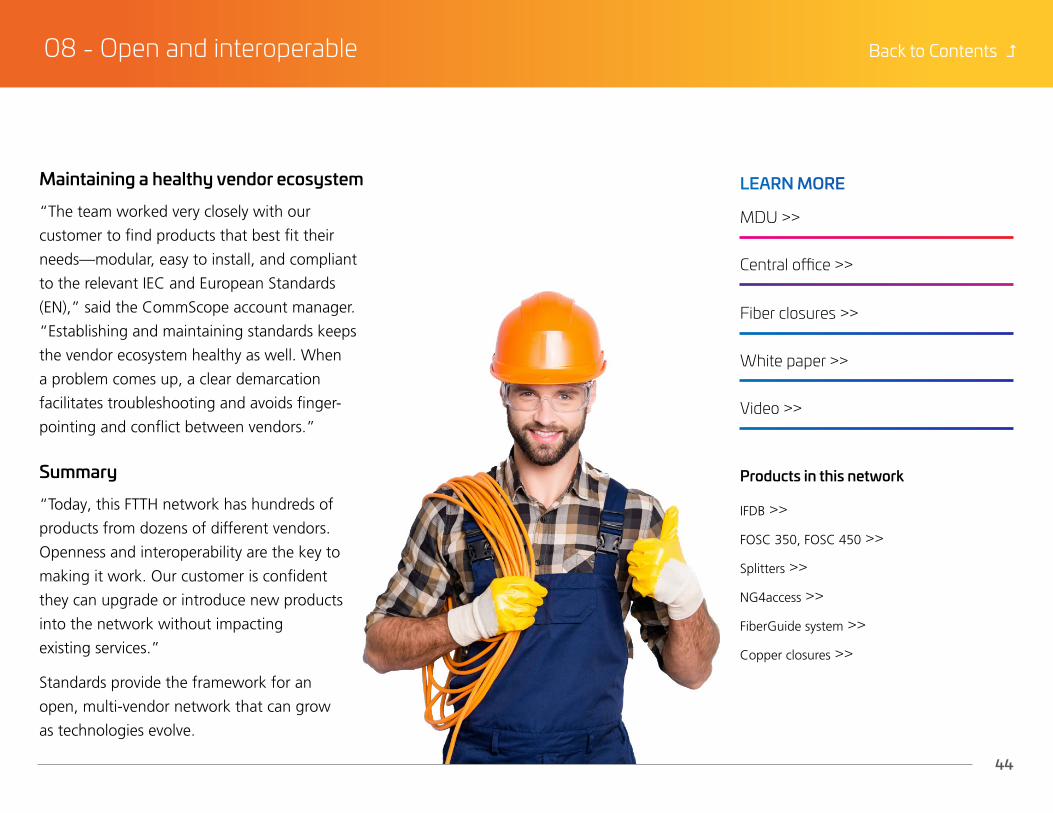
Maintaining a healthy vendor ecosystem
“The team worked very closely with our
customer to find products that best fit their
needs—modular, easy to install, and compliant
to the relevant IEC and European Standards
(EN),” said the CommScope account manager.
“Establishing and maintaining standards keeps
the vendor ecosystem healthy as well. When
a problem comes up, a clear demarcation
facilitates troubleshooting and avoids finger-
pointing and conflict between vendors.”
Summary
“Today, this FTTH network has hundreds of
products from dozens of different vendors.
Openness and interoperability are the key to
making it work. Our customer is confident
they can upgrade or introduce new products
into the network without impacting
existing services.”
Standards provide the framework for an
open, multi-vendor network that can grow
as technologies evolve.
MDU >>
IFDB >>
FOSC 350, FOSC 450 >>
Splitters >>
NG4access >>
FiberGuide system >>
Copper closures >>
Central office >>
Fiber closures >>
White paper >>
Video >>
LEARN MORE
Products in this network

Case Study
09 - An enclosure that goes the extra mile

Back to Contents =
46
09 - An enclosure that goes the extra mile
Fiber optic splice closures (FOSC®) are
essential for a modern network and in Asia-
Pacific there is intense competition for high
quality, low cost FOSC solutions. A large
APAC fiber-to-the-home (FTTH) operator
sought a durable and reliable closure
solution that would safeguard its broadband
network today and beyond while keeping
costs within reason.
There are many applications where an
external network has to operate under
various conditions and this makes FOSC vital
in protecting fiber nodes located outdoors.
FOSC must also deliver the maneuverability,
scalability and reliability a modern network
needs and they need to be easy to
maintain—all factors that directly impact an
operator’s capital expenditure (CAPEX) and
operating expenditure (OPEX).
Going the extra mileMoving fiber forward
Closures house and protect fibers and
modules at splice points and are critical to
expanding network capacity and productivity.
The operator chose FOSC, which combine
fiber management hardware with a highly
reliable sealing system. The CommScope
gel FOSC utilizes memory-function gel as a
sealing material which possesses both the
flexibility of artificial rubber and the sealing
qualities of grease.

Back to Contents =
47
09 - An enclosure that goes the extra mile
Megatrends drive the need for fiber connectivity

Back to Contents =
48
09 - An enclosure that goes the extra mile
Installation made easy
Reduced installation time was another key
factor in the operator’s decision to use
CommScope’s FOSC solution. CommScope’s
FOSC solutions are designed for installation
without special tools or skills. On-site
installation takes 15 percent less time than
with installing traditional “horseshoe” gel
closures. The operator would also reduce on-
site maintenance time by 30 percent using
CommScope’s FOSC solution.
Passing the weather test
CommScope’s FOSC solutions resist moisture,
vibration, temperature, chemicals and
ultraviolet rays thanks to advanced gel
technology that protects connections.
Back to Contents =
49
09 - An enclosure that goes the extra mile
Connections that count
CommScope’s FOSC solutions were designed
leveraging over 30 years of historical data on seal
performance from deployments across the globe. They
simplify splice management and maintenance. Our
customer has peace of mind their infrastructure will
be a stable platform for many years with the ability to
grow to meet increasing network demands.
Keep your network running, even in the harshest conditions.
Web page >>
Blog: Top 10 CommScope Innovations: Outside Plant Closure Solutions >>
LEARN MORE

www.commscope.comVisit our website or contact your local CommScope representative for more information.
© 2020 CommScope, Inc. All rights reserved.
All trademarks identified by ® or ™ are registered trademarks or trademarks, respectively, of CommScope, Inc. This document is for planning purposes only and is not intended to modify or supplement any specifications or warranties relating to CommScope products or services.
CO-114011.2-EN (03/20)
CommScope pushes the boundaries of communications technology with game-changing ideas and ground-breaking discoveries that spark profound human achievement. We collaborate with our customers and partners to design, create and build the world’s most advanced networks. It is our passion and commitment to identify the next opportunity and realize a better tomorrow.Discover more at commscope.com