inner harour log yard, port of lyttelton ... harour log yard, port of lyttelton, lyttelton: report...
TRANSCRIPT
INNER HARBOUR LOG YARD, PORT OF LYTTELTON, LYTTELTON: REPORT ON ARCHAEOLOGICAL MONITORING
HNZPT AUTHORITY 2015/635EQ
KURT BENNETT, JESSIE GARLAND AND CHRISTINE WHYBREW UNDERGROUND OVERGROUND ARCHAEOLOGY LTD
DECEMBER 2016
UNPUBLISHED REPORT FOR LYTTELTON PORT COMPANY

2
TABLE OF CONTENTS Introduction ......................................................................................................................................... 5
Methods .............................................................................................................................................. 6
Historical research ........................................................................................................................... 6
Archaeological monitoring .............................................................................................................. 7
Report .............................................................................................................................................. 7
Artefact analysis .............................................................................................................................. 7
Historical background .......................................................................................................................... 7
Results ............................................................................................................................................... 12
Stratigraphy ................................................................................................................................... 18
M36/220: Forbes building ................................................................................................................. 24
Historical background .................................................................................................................... 24
Results of archaeological monitoring ............................................................................................ 25
Artefact analysis ............................................................................................................................ 33
Discussion ...................................................................................................................................... 44
M36/229: Ōhinehou .......................................................................................................................... 44
Historical background .................................................................................................................... 44
Results of archaeological monitoring ............................................................................................ 45
M36/293: Erskine Bay seawall .......................................................................................................... 45
Historical background .................................................................................................................... 45
Results of archaeological monitoring ............................................................................................ 46
Artefact analysis ............................................................................................................................ 52
Discussion ...................................................................................................................................... 55
M36/299: Heywood’s jetty/Heywood’s and Forbe’s jetty ................................................................ 55
Historical background .................................................................................................................... 55
Results of archaeological monitoring ............................................................................................ 56
Discussion ...................................................................................................................................... 57
M36/300: Hargreaves’ store ............................................................................................................. 57
Historical background .................................................................................................................... 57
Results of archaeological monitoring ............................................................................................ 58
M36/302: Rail reclamation, northern reclamation ........................................................................... 60
Historical background .................................................................................................................... 60
Results of archaeological monitoring ............................................................................................ 61
Artefact analysis ............................................................................................................................ 76
Discussion ...................................................................................................................................... 85
M36/304: Railway lines associated with the Lyttelton railway......................................................... 85
Historical background .................................................................................................................... 85

3
Results of archaeological monitoring ............................................................................................ 86
Artefact analysis ............................................................................................................................ 90
Discussion ...................................................................................................................................... 92
M36/310: Cunningham’s store.......................................................................................................... 92
Historical background .................................................................................................................... 92
Results of archaeological monitoring ............................................................................................ 93
Discussion .................................................................................................................................... 101
M36/311: First eastern reclamation ............................................................................................... 101
Historical background .................................................................................................................. 101
Results of archaeological monitoring .......................................................................................... 102
Discussion .................................................................................................................................... 103
M36/318: Produce sheds ................................................................................................................ 103
Historical background .................................................................................................................. 103
Results of archaeological monitoring .......................................................................................... 104
Artefact analysis .......................................................................................................................... 113
Discussion .................................................................................................................................... 113
M36/337: Turntable and engine sheds ........................................................................................... 114
Historical background .................................................................................................................. 114
Results of archaeological monitoring .......................................................................................... 114
Discussion .................................................................................................................................... 121
M36/344: Brick barrel drains .......................................................................................................... 121
Historical background .................................................................................................................. 121
Results of archaeological monitoring .......................................................................................... 123
Discussion .................................................................................................................................... 125
Conclusion ....................................................................................................................................... 125
References ....................................................................................................................................... 127
Appendix: Methods of artefact analysis.......................................................................................... 130
Dating: the TPQ method .............................................................................................................. 130
Ceramic artefacts ........................................................................................................................ 130
Faunal material ............................................................................................................................ 131
Glass artefacts ............................................................................................................................. 131
Metal artefacts ............................................................................................................................ 131
Miscellaneous artefacts............................................................................................................... 132
Functional categories .................................................................................................................. 132
Discard protocol .......................................................................................................................... 132
Abbreviations .............................................................................................................................. 132
Appendix 2: Artefact spreadsheets ................................................................................................. 135

4
Assemblage quantification .......................................................................................................... 135
Ceramic ........................................................................................................................................ 136
Faunal .......................................................................................................................................... 139
Glass ............................................................................................................................................ 139
Metal ........................................................................................................................................... 144
Miscellaneous .............................................................................................................................. 146
Clay smoking pipes ...................................................................................................................... 147
Footwear ..................................................................................................................................... 147

5
INTRODUCTION
Subsequent to the earthquake on 22 February 2011 the inner harbour log yard (also known as Log yard 66) at Lyttelton Port underwent pavement repairs and the installation of stormwater pipes and services (Figure 1 and Figure 2). On 11 December 2014 Heritage New Zealand Pouhere Taonga issued an emergency authority (2015/635eq) under Clause 10 of the Canterbury Earthquake (Historic Places Act) Order 2011 to Lyttelton Port Company. This authority was issued to allow excavation for the reconstruction of the earthquake damaged pavement, installation of stormwater pipes, fittings and structures, water pipes fixings and structures, electrical trenches and installation of kerbs and channels. An authority was required as this area was occupied prior to 1900. As per condition 4 of the authority the earthworks at Log yard 66 were monitored by an archaeologist.
Figure 1. Lyttelton, showing the location of the inner harbour log yard (in red). Image: Google Maps.

6
Figure 2. The inner harbour log yard project boundaries (outlined in red). Image: Google Earth.
METHODS
Historical research
This historical narrative was prepared following desk top research only. The contemporary location and topography of the surrounding street layout were identified using Google Maps and Google Earth. Contemporary and historic aerial imagery of the location were compared via the Canterbury Maps GIS. Plans and photographs of Lyttelton Harbour from the 1850s to mid-20th century were consulted for descriptions of the area and infrastructural developments at Lyttelton Port of Christchurch. The sites discussed in this historical narrative were recorded in the New Zealand Archaeological Association Site Record database, ArchSite. These sites were mainly identified by Matt Carter in his archaeological assessment of Lyttelton Port of Christchurch (Carter 2014a). Lyttelton Port of Christchurch contains a high concentration of archaeological sites and those not recorded within the physical boundaries of the current archaeological authority are not discussed in this report. The specific sites affected by the proposed works under this archaeological authority were identified by Carter in his archaeological assessment for the Lyttelton Port of Christchurch inner harbour log yard (Carter 2014b). Research on the specific sites was undertaken through searches of contemporary newspapers accessed on the text-searchable database, Papers Past. Archives of the Canterbury Association and Canterbury Provincial Government, held at Archives New Zealand, were not fully consulted, in preference to secondary reporting in contemporary newspapers. All other known relevant sources were consulted in the preparation of this narrative. The historical research was carried out by Christine Whybrew.

7
Archaeological monitoring
The LPC CEMP guidelines required the repaving works to be investigated and recorded using standard archaeological practice. These methods included mapping archaeological features, recording stratigraphic profiles, and photographing the log yard before and after modification. Further, when archaeological features were exposed, they were photographed in situ and measurements recorded. Artefacts that were to be destroyed during works were recovered and taken back to Underground Overground Archaeology at 8/31 Stevens Street, Christchurch, for further analysis. All notes from the day to day monitoring were recorded in a field note book by the onsite archaeologist.
An archaeologist monitored the excavation that exposed archaeological features within the log yard works area. When the archaeologist was not present on site, the accidental discovery protocol (ADP) outlined in the LPC CEMP guidelines was employed.
The location of all archaeological features was recorded using a Trimble M3 DR 5 total station. Multiple station points and back sights were setup around Sutton Quay, Norwich Quay and the overpass opposite Oxford Street. This ensured it gave 100 percent coverage of the log yard and made it possible to record all features.
Two stratigraphic profiles were recorded during the excavation of the new stormwater drainage trenches, as these gave the greatest depth and cross section of the site.
All features recorded on site were assigned a sequential number.
Recording methods for each feature used a range of techniques. Photography was employed for all features where possible, typically with a 1 metre (m) scale (with 100 mm increments). Fewer details were recorded for those features left in situ (of which there were a number) than for those features that were removed.
Report
This report focuses on the 19th century features found during the archaeological work, with the 20th century features found mentioned in passing and their location recorded on the site plans. In addition, less detail is provided about those features left in situ than those that were removed.
Artefact analysis
Items were initially sorted according to material class (glass, ceramic, metal, miscellaneous) before being identified to individual types and forms. Details of the analytical methods used during this process are provided in Appendix 1. The assemblage was then quantified by the number of individual specimens present (NISP), from which a minimum number of vessels (MNV) or individuals (MNI) was calculated (there is a full list of the artefacts in Appendix 2). The artefact analysis was carried out by Jessie Garland.
HISTORICAL BACKGROUND1
Formed from the remnants of an extinct volcano, Lyttelton harbour has been the site of human activity for over 800 years (Rice 2004:14).
1 This section is not a full outline of the history of the Lyttelton Port but a summary of the relevant information. Extracted from Carter 2014a.

8
Prior to European settlement the harbour was known as Whakaraupō, or harbour of raupō (Burgess 2009:7). The first occupants of the area were Waitaha, followed by Ngāti Mamoe in the 16th century (Anderson 1998:22-23). For Ngāti Mamoe the area surrounding Lyttelton, which they named Ōhinehou, was a mahinga kai. The pioki, or gummy shark, was hunted there on a seasonal basis (R. Couch, pers. comm., 2011). Ngāti Mamoe was eventually displaced in the 18th century by Ngāi Tahu, who established a settlement at Rapaki (Anderson 1998:38). Rapaki later became a native reserve and is today the site of a marae. Ōhinehou (now Lyttelton) is noted as the place where an early 18th century Ngāi Tahu war party fought and defeated the resident mana whenua Ngāti Mamoe (Jolly 2013: 34). Māori travelled backwards and forwards across the Port Hills, between the settlements around Whakaraupō and the settlements and resources on the inland side of the hills. Both the Port Hills and Banks Peninsula provided access to forest-related resources, including a rich birdlife (Challis 1995). By the time the first Europeans arrived in the area the settlement at Ōhinehou appears to have been abandoned. Visiting French whalers described settlements at Whakaraupō as “a cluster of huts and some whata on which were stores of dried fish, sacks of kumara and cakes of roasted fern root” (Anderson 1998: 151). No Māori were recorded as living in this part of Whakaraupō between 1840 and 1861 (Anderson 1998: 151). By the 1820s the Ngāi Tahu population of Banks Peninsula was on the decline due to the Kai Huanga feud. The population suffered a further decrease in the 1830s following the massacres of the Ngāti Toa war chief Te Rauparaha (Rice 2004:14). Lists of Māori settlement sites of the early 19th century have been compiled from traditional and historical sources (Anderson 1988: Figs. 14 and 15; Orchiston 1974: Table 2.5). By this stage there had been a migration of populations to the Horomaka harbours frequented by trading vessels and whaling ships, particularly to Akaroa, Koukourarata (Port Levy), and Whakaraupō (Anderson 1988: 34-35, 76). Despite this, European vessels still visited the Banks Peninsula region in order to trade with the local inhabitants. It was a flax trader, Captain William Wiseman, working on behalf of Australian merchants Cooper and Levy, who gave Lyttelton its first European name: Port Cooper. Although British, French and American whaling vessels visited the harbour, Akaroa remained the main port of call for the Banks Peninsula region (Rice 2004: 14-17). During this early period of Māori-European interaction, local Māori had a market area – and several whare – at the east end of Norwich Quay (now recorded as archaeological site M36/229). This was subsequently moved to the west end of the original foreshore, around the corner of Norwich Quay and Dublin Street, including Sutton Reserve and the area around the Moorhouse tunnel mouth. Both these areas were also the site of fishing villages before European arrival in the area (Burgess 2009: App. 4). Following the establishment of a farm by the Deans family on the Canterbury plains, Port Cooper was used as a landing site for surveyors who were looking to establish a colony on the plains. The plan for a British colony at Whakaraupō was prepared in 1847 by Edward Gibbon Wakefield and John Robert Dudley. In 1848 they formed the Canterbury Association with the support of the Anglican church. Originally the main settlement in Canterbury was to be called Lyttelton, after the association’s chairman, George William Lyttelton, 5th Baron Lyttelton. However, the association decided to name its first settlement, that which was established at Port Cooper, after Lyttelton instead (Rice 2004:17). In 1848 Captain Joseph Thomas was sent by the association to survey the region and plan the new settlement. Initially Thomas suggested the establishment of a settlement at Teddington, but he later realised that the process of reclamation would prove to be too expensive (Rice 2004:17). With the

9
main settlement being relocated to the plains, Thomas moved the site of the main port to what was then known as Erskine Bay in Port Cooper (Rice 2004:18). By September 1849, Thomas (with the help of Charles Torlesse) had surveyed the proposed site for the Lyttelton settlement. The street plan was drafted by Edward Jollie (Rice 2004:18). The settlement was officially gazetted as a port of entry on 30 August 1849. The following year saw the arrival of the so-called first four ships, which brought the Canterbury Association’s first settlers to Canterbury. By the end of the year the settlement had grown to include a jetty, a customs house, a hotel, barracks and 25 houses (Rice 2004:19). There were, however, concerns that the harbour was unsuitable for a port. Engineers suggested that the neighbouring Gollans Bay would be a more appropriate location as it would allow larger vessels to dock and unload. Regardless, efforts were taken to ensure that Lyttelton could accommodate the growing number of vessels. One such progressive individual was the merchant, John Thomas Peacock, who in 1857 oversaw the construction of a second jetty on Norwich Quay (Scotter 1968:62). The construction of the second jetty led to an increase in shipping, which resulted in a rise in exports (Scotter 1968:63). By 1859 a sea wall was built on either side of the government wharf (Rice 2004:26). However, criticism of the port continued, especially since many vessels were forced to berth further out in the harbour and be unloaded through the use of lightermen (Scotter 1968:67). Some cargo vessels took weeks to unload (Rice 2004:25). Against the backdrop of these developments, plans were also being made to connect the port to Christchurch via railway. The concept of a railway linking the port town of Lyttelton with Christchurch had been the hope of many early English settlers in Lyttelton, who had left their homeland at a time when the railway industry was rapidly expanding (Scotter 1968:63). However, it was not until an English engineer, G.R. Stephenson, had completed a report in 1859 that the idea was given official consideration. Work began on the tunnel in 1860 but was hindered by hard rock and the lack of available men due to the lure of the gold rush taking place on the West Coast. The tunnel was finally opened in 1867 (Rice 2004: 33). The railway contributed significantly to the development of Lyttelton and the tunnel became known as the “throat of the province” (Rice 2004:29). During construction there were proposals for the railway to continue as far as Gollans Bay, which was still considered to be the more appropriate location for a port. However, Stephenson argued in favour of Lyttelton and suggested that land should be reclaimed (Scotter 1968:68). Edward Dobson, a member of the railway commission established by the council, suggested that the tunnel should be straightened in order for the railway line to continue as far as a jetty, which would extend out into the harbour (Scotter 1968:68). This was accepted by the contractors, who felt that a straight tunnel was safer. The plans were also accepted by the provincial government when Dobson presented them in 1862 (Scotter 1968:68). However, the plans were opposed by some members of the council and this disagreement led to the establishment of the Lyttelton Wharf Commission in November of that year. The commission’s priority was to determine the most appropriate location for a wharf that would accommodate larger vessels. However, because the commission was largely composed of individuals who were merchants and vessel masters, the organisation favoured plans that emphasised the needs of shipping rather than rail (Scotter 1968:69). Instead of Dobson’s plan of an extended wharf, the commission suggested that a breakwater, extending from Officers Point, with a wharf, should be formed. The submissions were put before an English commission, which dismissed them all save for that of the local commission. The English

10
commission suggested that as well as a breakwater from Officers Point, a second breakwater extending from Naval Point should be constructed (Scotter 1968:71). In July 1859 further work was undertaken on the government wharf that saw it extended with screw piles. An embankment with a wooden seawall was constructed between the jetty and the reclamation at the mouth of the tunnel. A short jetty was also built at the western end of this seawall (the lighter jetty). The seawall and the short jetty were contracted to E.G. Wright, an engineer, while the screw pile jetty was overseen by Alexander Cairns. Progress was slow, however, due to the peculiarities of the Lyttelton mud, and in October 1866 the government took over the work on the screw-pile jetty (Scotter 1968:74). Work was also undertaken on building the breakwater from Officers Point through the use of prison labour (Scotter 1968:75). The need for breakwaters was confirmed when a tsunami hit the port in August 1868 (Rice 2004:38). With the completion of the railway tunnel in 1867 attention was once again focused on the need for adequate berthage (Scotter 1968:77). The 1870s saw an increase in grain production in Canterbury and therefore the port was forced to deal with a high volume of exports (Scotter 1968:80). John Marshman, the general manager of the Canterbury provincial railways, stressed the need for a third wharf in order to cope with the demands (Scotter 1968:81). In 1872, in order to ensure that the plans for harbour development would meet government approval, Superintendent William Rolleston requested that the Minister of Public Works provide him with the services of John Carruthers, the engineer in chief for the New Zealand government, and his assistant, John Blackett. The report they produced recommended that the harbour be dredged, that the Officers Point breakwater be extended, that another wharf capable of carrying railway lines be built, along with another breakwater and that a jetty for lighterage be erected at the tunnel mouth (Scotter 1968:84). In December 1873 the firm Hawkins, Stock and Company signed the contracts for the Officers Point mole and wharf and the Naval Point breakwater. Another company, Connor and McKay, oversaw the construction of the lighterage jetty. The contracts were eventually taken over by a newly formed firm, that of Hawkins and Martindale (Scotter 1968:84). The breakwater wharf was formally opened in February 1874 and was named Gladstone pier after the first ship to dock there, W.E. Gladstone. The breakwaters were completed in 1876 (Scotter 1968:84). The dredge, Erskine, started its work deepening the harbour in August of that year, accompanied by the hopper barges, Sumner and Heathcote (Rice 2004:42). Apart from sporadic work in 1887 and 1890 the dredge and barges were made redundant in 1886 (Rice 2004:51). As a result of this dredging the need for lightering steadily began to decline (Scotter 1968:87). These developments led to an increase in shipping, both domestic and international (Rice 2004:42). In 1876 the provincial government was disestablished and the Lyttelton Harbour Board took over the management of the port. The composition of the board represented the two groups that had vested interests in the growth of the port, businessmen and farmers (Rice 2004:43). In 1878 the harbour board started on new projects, the first of which was the construction of a graving dock. The £92,000 contract for this was given to Ware and Jones and the firm was required to cut away the Naval Point hill and reclaim the land (Scotter 1968:136). There were delays, however, due to the need for the cassion (floating gateway) to be delivered from Glasgow. When it finally opened on 3 January 1883 there was a large celebration, with trains bringing guests to a ceremony held in the export shed (Scotter 1968:137).

11
Although the graving dock allowed the Lyttelton Harbour Board to repair its own vessels, it was not used enough to recover the cost of its construction (Scotter 1968:138). The transition from sail to steam also meant that it was unable to accommodate new and larger vessels (Rice 2004:48). Built in 1884 and situated next to the graving dock was a patent slip designed by C. Napier Bell and constructed by John Stinson (Scotter 1968:138). In 1885 Peacock’s wharf was replaced by the new No. 7 ocean steamer wharf, which was also designed by Bell (Scotter, 1968:139). As well as harbour improvements, the 1880s also saw the installation of military defences. The threat of war in Europe in 1878 resulted in the New Zealand government obtaining four guns from Britain (Scotter 1968:145). These were placed on Gladstone pier in 1879 and in the following year the naval brigade was formed (Rice 2004:53). The Russian incursion into Afghanistan in 1885 led to further defensive measures, with the installation of a 64 pounder gun at Officers Point and the formation of N Battery of the New Zealand Naval Volunteers (Rice 2004:53). The 1880s also saw the formation of a union for the Lyttelton waterside workers (Rice 2004:51). Working conditions in the port were rough, with long hours and constant danger. Despite this, the men who worked the port were not the underclass found in other city ports, but rather men who lived and socialised together with their fellow workers and overseers (Scotter 1968:151). Although the 1880s was a time of economic depression for New Zealand, Lyttelton was fortunate, as the Canterbury wheat boom and the export of frozen meat to Britain kept the worst effects of the depression at bay (Rice 2004:44). When the 1890 maritime strike, which had its origins in Australia, reached New Zealand, the workers of Lyttelton joined in August of that year. Although the strike only lasted until October, there were still instances of disorder (Rice 2004:51). The Lyttelton Harbour Board was pressured by bodies representing Canterbury farmers and was forced to intervene and ensure that the work continued (Scotter 1968: 152). As a result of the strike the Canterbury Employers’ Association prevented unionists from working at the Lyttelton docks (Rice 2004:52). The 1890s saw the end of the depression and an increase in the number of ships (Rice 2004:60). One of the new developments was the formation in 1895 of an interisland ferry service to Wellington. The Penguin was the first vessel to offer such transport and this was expanded upon in the following year by the Union Steamship Company (Rice 2004:62). The impact of the ferry service meant that by the early 1900s the No. 2 wharf became known as the ferry wharf (Rice 2004:69). The dawn of the 20th century was marked by Lyttelton being the port of operations for three expeditions to Antarctica, culminating in Robert Falcon Scott’s ill-fated 1910-1912 voyage (Rice 2004:66). Lyttelton was chosen most likely due to its close proximity to the Ross Sea area and because R.J. Scott, the professor of engineering at Canterbury University College, was Scott’s cousin (Scotter 1968:177). The 1900s also saw a renewal of dredging as none had taken place since 1895 and as a result there had been a gradual accumulation of silt. The Lyttelton Harbour Board purchased the dredge Manchester to undertake this work in 1900 (Scotter 1968:159). However, the renewal of dredging led to disagreements among the harbour board as to where the spoil should be dumped (Scotter 1968: 162-163). In 1909 it was finally decided to start a process of reclamation behind the breakwater at Naval Point (Scotter 1968:163). The Naval Point reclamation was eventually finished in 1925. After the land had settled railway lines and roads were laid across its surface. Oil companies such as Vacuum Oil and British Imperial Oil then

12
used the land to construct their new storage facilities. Many of these oil tanks were constructed by the local engineering firm, Andersons’ engineering works (Rice 2004:92). With the economic downturn following World War I, the depression of the 1930s and then the outbreak of the World War II in 1939, there were no major construction projects at the port until the 1950s. In 1951 the Lyttelton Harbour Board Empowering Act was passed by parliament, granting a loan for the improvement of the No. 7 jetty. In the following year the loan was increase so that further repairs could be made to the ferry wharf. A second tunnel was also built during this period (Scotter 1968:289). A new reclamation project, situated between Windy Point and Gladstone pier, started in 1957. This was designed by James A. Cashin, the former senior assistant engineer at the port of Liverpool. By creating a new eastern reclamation, Cashin aimed to create more room for cargo handling, as well as a new site for transit sheds (Rice 2004: 119). The construction was a lengthy process, as tests had to be carried out by a British hydraulic research station based at Wallingford in Berkshire. Because the liquid mud of Lyttelton harbour had to be overcome by unique methods of engineering, the construction of the reclamation was visited by many overseas experts (Rice 2004: 120). The new eastern reclamation, named Cashin Quay, was opened in 1964 (Rice 2004:122). This quay provided the ample space required for the newly implemented cargo containers and in 1973 the container wharf was opened (Rice 2004:134). At the time Lyttelton, along with Port Chalmers, was one of only two cargo container ports in the South Island (Rice 2004:135). The Lyttelton Harbour Board continued to manage the port until October 1989 when the organisation was disestablished by the Port Companies Act 1988 and taken over by the Lyttelton Port Company (Rice 2004: 137-138). The 1980s also saw the removal of the oil storage tanks at Dampiers Bay following an explosion in 1985, and the replacement of the 1884 patent slip in 1987 (Rice 2004: 143). The changes implemented by the Lyttelton Harbour Board saw the formation of various heritage groups who sought to preserve the maritime history of the port. One such group, the Norwich Quay Preservation Society, assisted in the removal of the historic signal box from its original site to a new location opposite the Lyttelton Historical Museum (Rice 2004:149). Despite this, the historic crane Rapaki and the Te Whaka dredge were unable to remain in situ. Since they belonged to the company they were put up for sale, and then relocated to Auckland and Dunedin (Rice 2004:147). The last of the port’s electric cranes were removed in 1994 and replaced by modern equivalents (Rice 2004: 147). Despite the damage caused by the 2010-2011 Canterbury earthquakes, the port of Lyttelton continues to operate in its original role as an export and import zone between the South Island and the rest of the world.
RESULTS
Between 3 March 2015 and 6 May 2016, earthworks for the reconstruction of earthquake damaged pavement; installation of stormwater pipes, fittings and structures, water pipes fixings and structures; electrical trenches; and installation of kerbs and channelling was carried out by Higgins (formerly Calcon; Table 1). With the exception of the localised stormwater-related works, the maximum depth of earthworks was no more than 600 mm. Kurt Bennett, Peter Mitchell, Kirsa Webb, Hamish Williams and Luke Tremlett (Underground Overground Archaeology) monitored the work. The works were carried out in four separate stages (Figure 3). A total of 79 archaeological features were recorded (Figure 4, Figure 5, Figure 6 and Figure 7; Table 1).

13
Figure 3. Log yard 66: stage 1 (yellow), stage 2 (blue), stage 3 (green) and stage 4 (red). Image: Google Earth.
Table 1. Summary of earthworks during archaeological monitoring.
Component Stage area Depth of excavation
Notes
excavation across site for resurfacing preparation
All 600 mm Remove previous hardfill and soft spots to prepare for new hardfill and resurfacing of pavement.
installation of stormwater pipes
1 and 2 4500 mm (max) Installation of new concrete stormwater pipes Orientated northwest-southeast. These new concrete pipes connected into the existing cast iron stormwater drains that service Lyttelton.
excavation and installation of stormwater catchment
3 2500 mm (max) Large stormwater concrete catchment measured 4500 mm in length by 3000 mm in width.

14
Figure 4. Site plan of stage 1 works. New stormwater pipes and stratigraphic profile shown with green line.

15
Figure 5. Site plan of stage 2 works. New stormwater pipes and stratigraphic profile 2 shown with green line.
16
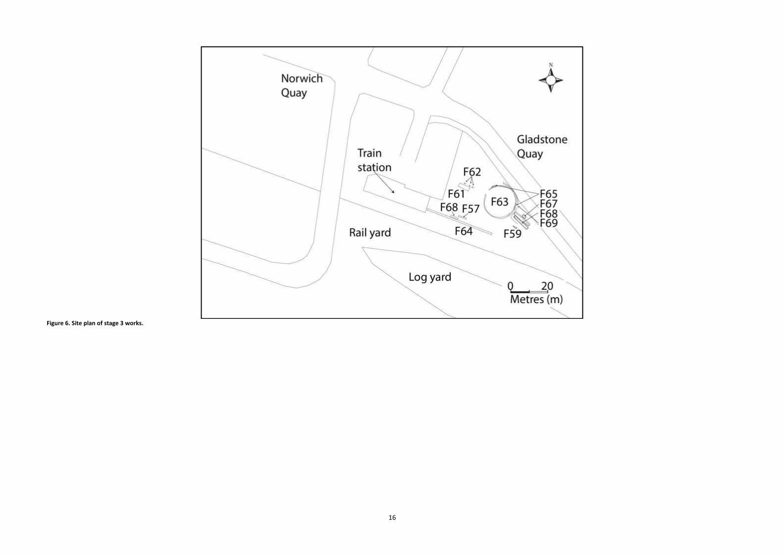
Figure 6. Site plan of stage 3 works.

17
Figure 7. Site plan of stage 4 works.

18
Table 2. Archaeological features and recorded archaeological sites within the project boundaries.
ArchSite ArchSite name/description
Feature number(s) Description
M36/220 Forbes building 2, 22, 31, 34, 36, 37, 39 Slate lined drain, individual artefacts, timber posts, concrete building foundation.
M36/229 Ōhinehou NA NA
M36/293 Erskine Bay seawall 14, 23, 25, 26, 35 Timber structure.
M36/299 Heywood’s jetty/Heywood’s & Forbe’s jetty
30 Timber post.
M36/300 Hargreaves’ store NA NA
M36/302 Rail reclamation, northern reclamation
9, 11, 12, 13, 15, 16, 17, 18, 19, 20, 24, 50, 51, 53, 54 55, 56, ST1, 71
Rock with possible evidence of mining activity, individual artefacts (faunal and cultural), scrap timbers.
M36/304 Railway lines associated with the Lyttelton railway
1, 7, 28, 29, 32, 38 Railway track spikes, railway sleepers, railway track.
M36/310 New Zealand Loan & Mercantile Co grain store
70, 73, 75, 76, 77, 78, 79, 80, 81, 82
Post holes, brick foundation, timber posts.
M36/311 First eastern reclamation
61 Possible timber structure associated with first reclamation.
M36/318 Produce sheds 5, 42, 44, 45, 46, 49, 52 Brick sump, timber structures, clay drain pipes, brick building foundation, concrete foundations.
M36/337 Turntable & engine sheds
62, 63, 65, 66, 67, 68, 69 Possible concrete foundations for engine sheds, concrete train turntable, timber capping.
M36/344 Brick barrel drains 10 Cast iron pipe.
20th century
3, 8, 27, 33, 41, 43, 47, 57, 72, 74
Concrete structures, corrugated metal, brick rubble, brick floor.
unknown 21 Possible manual jack or hardstand.
Stratigraphy
Stage 1 stratigraphy The stratigraphy of the stage 1 drain works was 50 metres in length, orientated northwest- southeast. The following strata were recorded in the south baulk (Figure 8 and Figure 9):
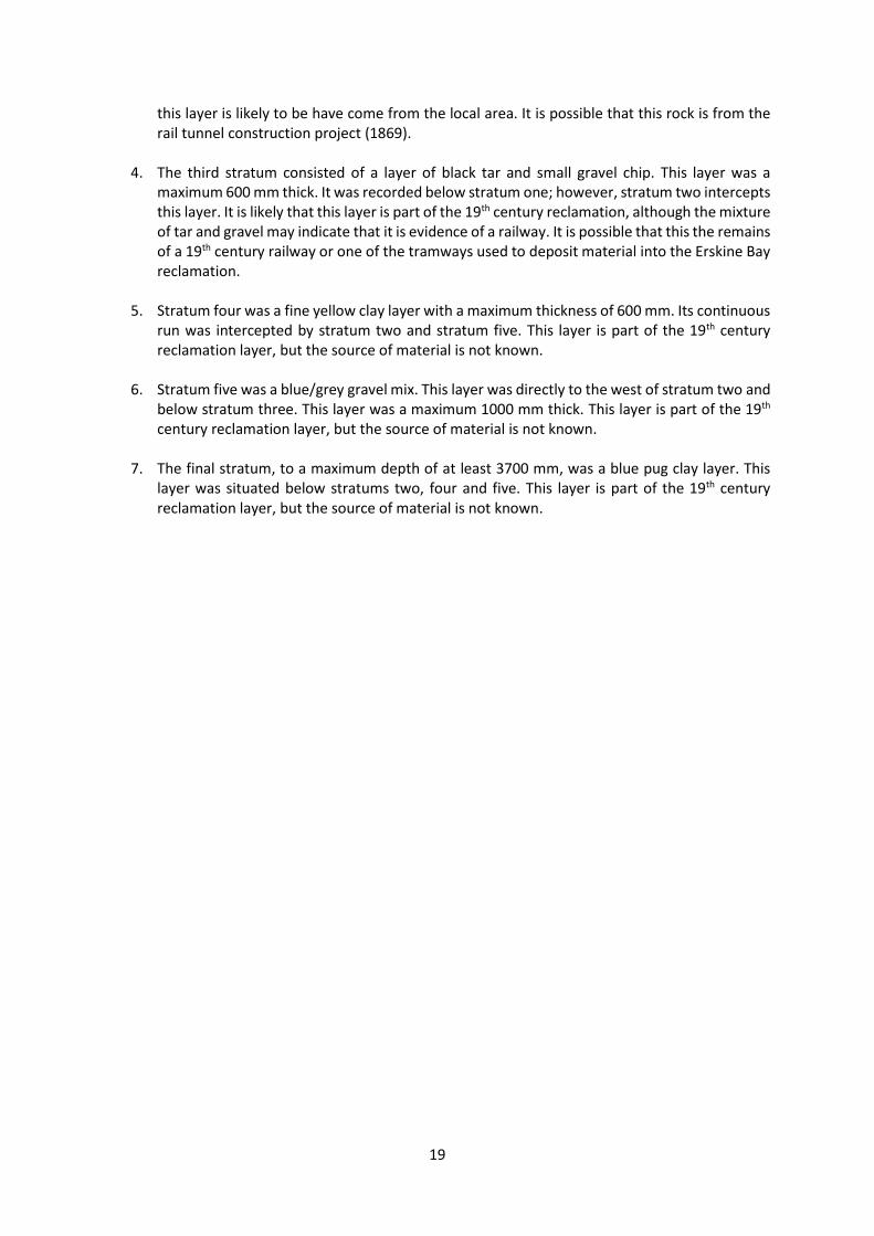
1. The first stratum was a layer of compacted stone, which was a pit run/modern fill layer. This layer was a maximum of 1100 mm in depth. This layer was deposited during the repaving works for this project.
2. There was a lens of dark shingle between stratums one and four. It was approximately 2 metres in length and 400 mm thick. This layer is likely to be a small deposit as part of the reclamation.
3. The second stratum was a layer of volcanic rock (a range of sizes), sharp and angular in shape. This layer intercepts the continuous layer of stratum 3 and was approximately 1800 mm thick. This layer is part of the 19th century reclamation fill. Due to the volcanic nature of the rock,
19
this layer is likely to be have come from the local area. It is possible that this rock is from the rail tunnel construction project (1869).
4. The third stratum consisted of a layer of black tar and small gravel chip. This layer was a maximum 600 mm thick. It was recorded below stratum one; however, stratum two intercepts this layer. It is likely that this layer is part of the 19th century reclamation, although the mixture of tar and gravel may indicate that it is evidence of a railway. It is possible that this the remains of a 19th century railway or one of the tramways used to deposit material into the Erskine Bay reclamation.
5. Stratum four was a fine yellow clay layer with a maximum thickness of 600 mm. Its continuous run was intercepted by stratum two and stratum five. This layer is part of the 19th century reclamation layer, but the source of material is not known.
6. Stratum five was a blue/grey gravel mix. This layer was directly to the west of stratum two and below stratum three. This layer was a maximum 1000 mm thick. This layer is part of the 19th century reclamation layer, but the source of material is not known.
7. The final stratum, to a maximum depth of at least 3700 mm, was a blue pug clay layer. This layer was situated below stratums two, four and five. This layer is part of the 19th century reclamation layer, but the source of material is not known.
20
Figure 8. Stratigraphic profile recorded during stormwater excavation, stage 1, facing south.
21
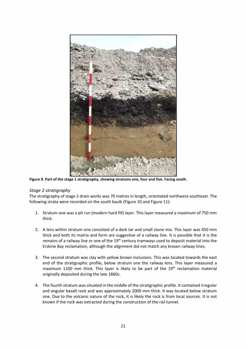
Figure 9. Part of the stage 1 stratigraphy, showing stratums one, four and five. Facing south.
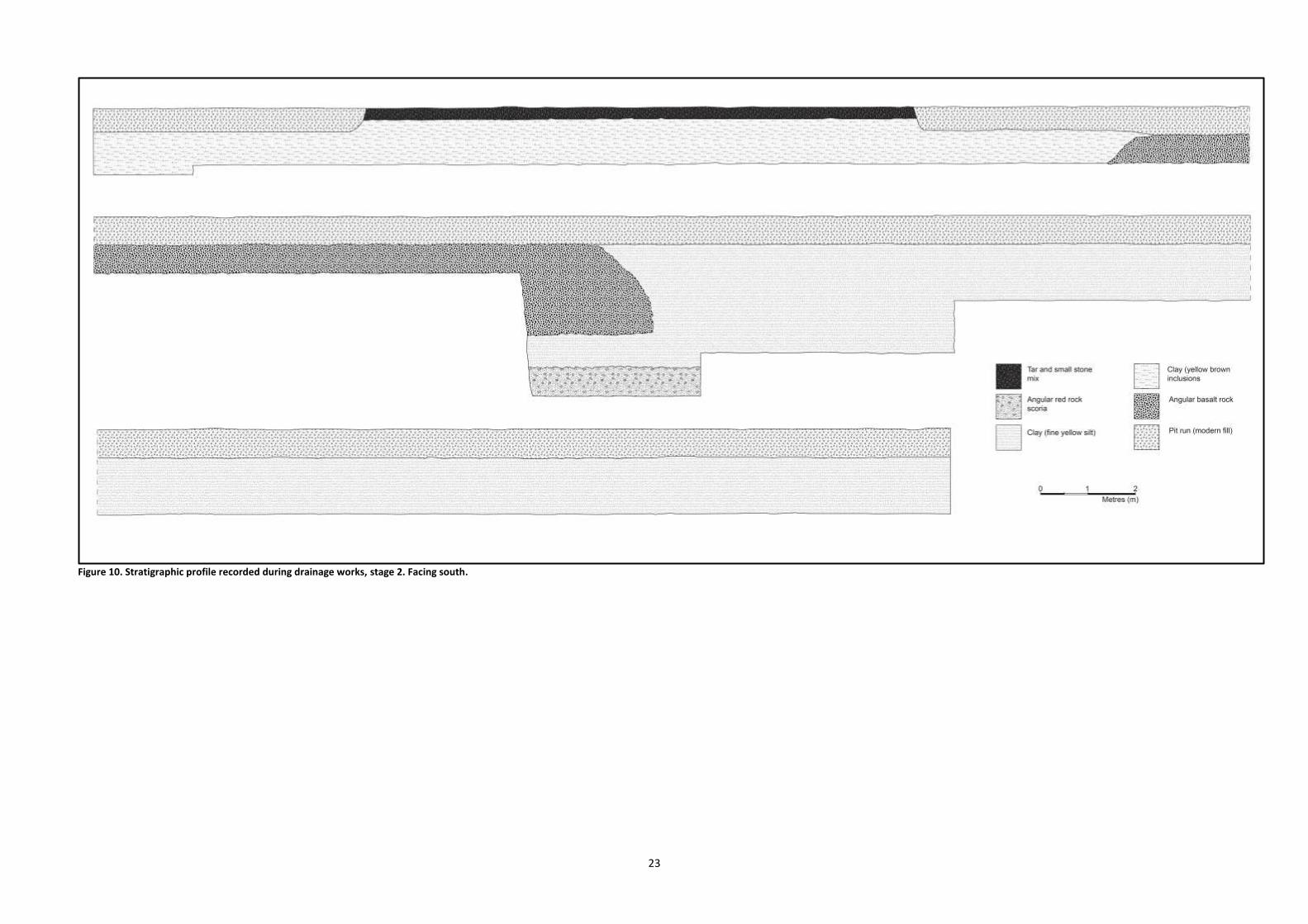
Stage 2 stratigraphy The stratigraphy of stage 2 drain works was 70 metres in length, orientated northwest-southeast. The following strata were recorded on the south baulk (Figure 10 and Figure 11):
1. Stratum one was a pit run (modern hard fill) layer. This layer measured a maximum of 750 mm thick.
2. A lens within stratum one consisted of a dark tar and small stone mix. This layer was 450 mm thick and both its matrix and form are suggestive of a railway line. It is possible that it is the remains of a railway line or one of the 19th century tramways used to deposit material into the Erskine Bay reclamation, although the alignment did not match any known railway lines.
3. The second stratum was clay with yellow brown inclusions. This was located towards the east end of the stratigraphic profile, below stratum one the railway lens. This layer measured a maximum 1100 mm thick. This layer is likely to be part of the 19th reclamation material originally deposited during the late 1860s.
4. The fourth stratum was situated in the middle of the stratigraphic profile. It contained irregular and angular basalt rock and was approximately 2000 mm thick. It was located below stratum one. Due to the volcanic nature of the rock, it is likely the rock is from local sources. It is not known if the rock was extracted during the construction of the rail tunnel.

22
5. To the west of stratum four and below stratum one, stratum five was a clay (fine yellow silt). It was a maximum depth of 3200 mm. It is likely this is 19th century reclamation fill.
6. Stratum six consisted of angular red rock scoria and fine sediments. This layer was directly below stratum five. It is likely this layer is natural bedrock/beach rock as it was inundated during high tide with no evidence of the rock being dressed.
23
Figure 10. Stratigraphic profile recorded during drainage works, stage 2. Facing south.
24
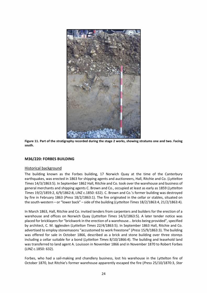
Figure 11. Part of the stratigraphy recorded during the stage 2 works, showing stratums one and two. Facing south.
M36/220: FORBES BUILDING
Historical background
The building known as the Forbes building, 17 Norwich Quay at the time of the Canterbury earthquakes, was erected in 1863 for shipping agents and auctioneers, Hall, Ritchie and Co. (Lyttelton Times 14/3/1863:5). In September 1862 Hall, Ritchie and Co. took over the warehouse and business of general merchants and shipping agents C. Brown and Co., occupied at least as early as 1859 (Lyttelton Times 19/2/1859:2, 6/9/1862:8, LINZ c.1850: 632). C. Brown and Co.’s former building was destroyed by fire in February 1863 (Press 18/2/1863:1). The fire originated in the cellar or stables, situated on the south-western – or “lower back” – side of the building (Lyttelton Times 18/2/1863:4, 21/2/1863:4). In March 1863, Hall, Ritchie and Co. invited tenders from carpenters and builders for the erection of a warehouse and offices on Norwich Quay (Lyttelton Times 14/3/1863:5). A later tender notice was placed for bricklayers for “brickwork in the erection of a warehouse... bricks being provided”, specified by architect, C. M. Igglesden (Lyttelton Times 22/4/1863:5). In September 1863 Hall, Ritchie and Co. advertised to employ stonemasons “accustomed to work freestone” (Press 15/9/1863:3). The building was offered for sale in October 1866, described as a brick and stone building over three storeys including a cellar suitable for a bond (Lyttelton Times 8/10/1866:4). The building and leasehold land was transferred to land agent A. Louisson in November 1866 and in November 1870 to Robert Forbes (LINZ c.1850: 632). Forbes, who had a sail-making and chandlery business, lost his warehouse in the Lyttelton fire of October 1870, but Ritchie’s former warehouse apparently escaped the fire (Press 25/10/1870:3, Star

25
26/10/1870:2). However, in February 1884 the interior of Forbes’ store was “completely gutted” by a serious fire which began at the back of the building of the ground floor (Star 18/2/1884:3). Tenders for rebuilding Forbes’ store were invited from builders by J. S. M. Jacobsen, architect, in April 1884 (Press 4/4/1884:4). The building was demolished after the earthquakes of 2010-11 and these works were monitored by an archaeologist. As a result of this work this site was recorded as archaeological site M36/220 (Bowron-Muth 2011).
Results of archaeological monitoring
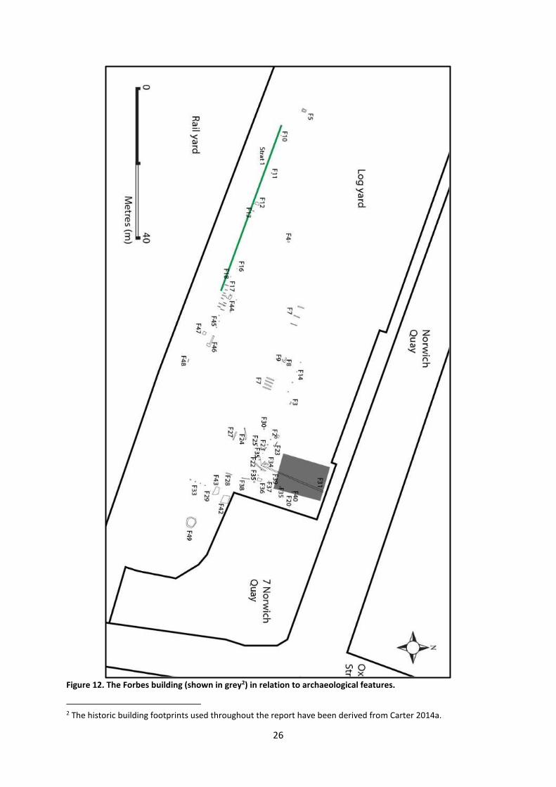
Eight features were found within or near the footprint of the Forbes building (Figure 12). The archaeological evidence indicated that Feature 31 was the east foundation of the Forbes building, indicating that the known historical footprint of the building was both too short (in a southerly direction) and not quite in the right position. Based on the information recorded during the archaeological monitoring, the building is likely to have extended from Norwich Quay almost to the Erskine Bay seawall (M36/293; see below).
26
Figure 12. The Forbes building (shown in grey2) in relation to archaeological features.
2 The historic building footprints used throughout the report have been derived from Carter 2014a.

27
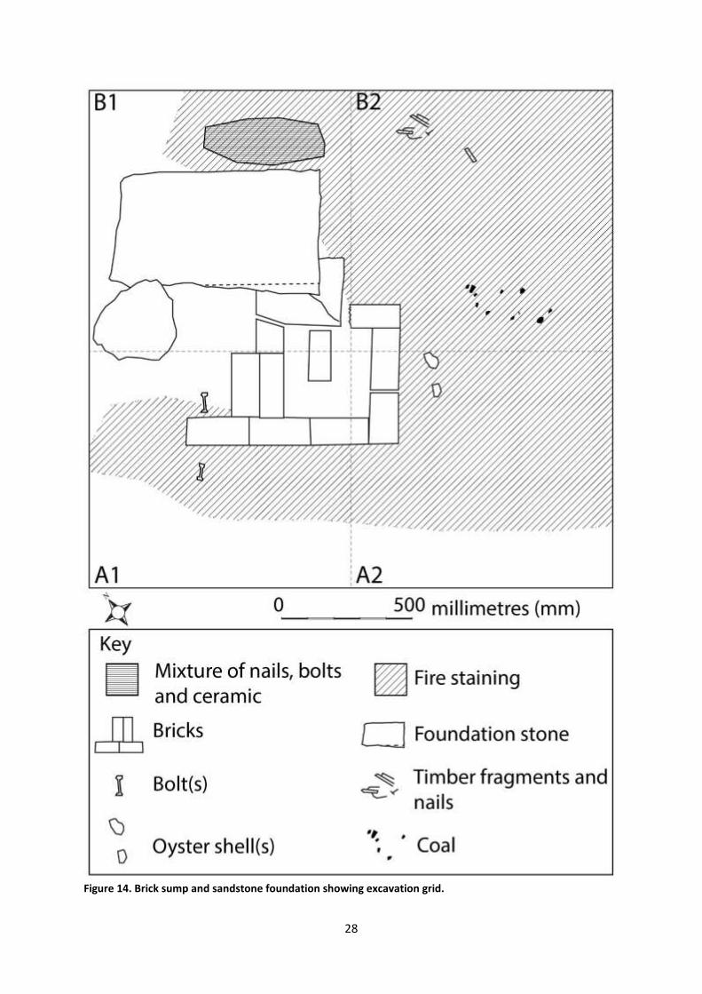
Feature 2 A brick sump and a sandstone foundation were exposed at a depth of 230 mm and located within a compacted yellow clay, probably on the southwest corner of the Forbes building (Figure 13 and Figure 14). This feature was identified as a sump due to a hole or depression in the bricks that appeared to indicate where an earthenware drain pipe had been removed. The sump consisted of red pressed bricks (suggesting 19th century manufacture), with no frog marks. The bricks were stacked two courses high, and the feature appeared to have had a brick floor. The sandstone block consisted of one worked stone block and measured 600 mm in length by 500 mm in width by 350 mm in depth. This sandstone block (and thus the sump) may have been associated with the 1863 building, which was described as being of brick and stone. Photographs taken during the 2011 demolition indicate that the lowest floor of the building was stone (ArchSite 2014). Feature 2 was excavated in a 2 metre by 2 metre area (Trench 1). This area was divided into 1 metre by 1 metre squares and material was then recovered to according to square. Feature 2 was removed during the course of earthworks.
Figure 13. Brick sump and sandstone foundation. Facing northwest.
28
Figure 14. Brick sump and sandstone foundation showing excavation grid.

29
Feature 22 A drain was exposed at a depth of 500 mm and located in a compacted yellow clay, immediately to the east of Feature 31 (the east foundation of the Forbes building, see below; Figure 15). The drain was orientated northeast-southwest and measured 3400 in length. Slate was used as the base of the drain with sides made from red scoria. The drain remains in situ and was covered with geotextile matting to help protect the slate from the modern backfill. Some artefacts were recovered from the drain fill. It is possible that this drain was constructed to carry water away from the Forbes building.
Figure 15. Slate and scoria drain. Facing southeast.
Feature 31 Feature 31 was exposed on the site’s surface before earthworks commenced in the area, and was longer than the historical information about the building’s footprint, indicating that that information was not accurate (Figure 12). Photographs taken during the building’s demolition indicate that this is likely to have been the east foundation of the building. This foundation was concrete, topped with slate damp-proof coursing that had been left in situ following the demolition of the Forbes building (Figure 16). The foundation measured 9960 mm in length by 480 mm in height and was orientated northeast-southwest. The concrete contained 35-50 mm round aggregate, with brick rubble and red rock to pack out the wall. Slate measuring 6-8 mm thick was used as a damp-proof coursing on top of the foundation (Figure 17). This wall was removed during earthworks.

30
Figure 16. Concrete building foundation wall from 17 Norwich Quay. Facing east.
Figure 17. Slate used as capping on top of the concrete foundation.
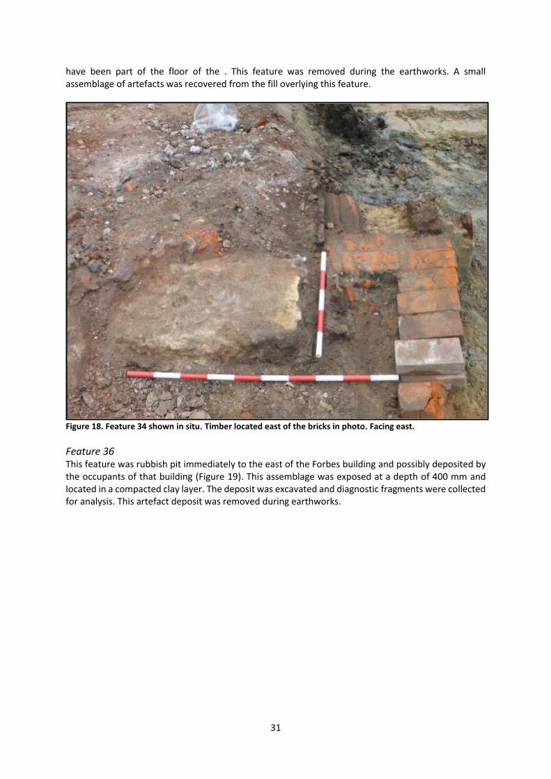
Feature 34 A brick structure, foundation stone and timber were exposed at a depth of 450 mm in a compacted clay and rubble mix, immediately to the west of Feature 31 and within the footprint of the Forbes building (Figure 18). The foundation stone measured 650 mm by 450 mm (i.e. of similar dimensions to the foundation block recorded as part of Feature 2). It was sandstone and was no doubt associated with the Forbes building. The red bricks were of a similar style to those recorded as part of Feature 2, being pressed and having no maker’s marks. There was two courses of bricks. The timber was very degraded, although it appeared to have been flooring sitting directly on top of a clay base, and may
31
have been part of the floor of the . This feature was removed during the earthworks. A small assemblage of artefacts was recovered from the fill overlying this feature.
Figure 18. Feature 34 shown in situ. Timber located east of the bricks in photo. Facing east.
Feature 36 This feature was rubbish pit immediately to the east of the Forbes building and possibly deposited by the occupants of that building (Figure 19). This assemblage was exposed at a depth of 400 mm and located in a compacted clay layer. The deposit was excavated and diagnostic fragments were collected for analysis. This artefact deposit was removed during earthworks.

32
Figure 19. Feature 36 in situ before excavation.
Feature 37 A square timber post was exposed at a depth of 400 mm and measured 250 mm by 250 mm, to the east of the Forbes building. A timber sample was collected and identified by Dr Rod Wallace as matai (Podocarpus spicatus). The post was cut down to the excavation depth of 600 mm and the remainder left in situ.
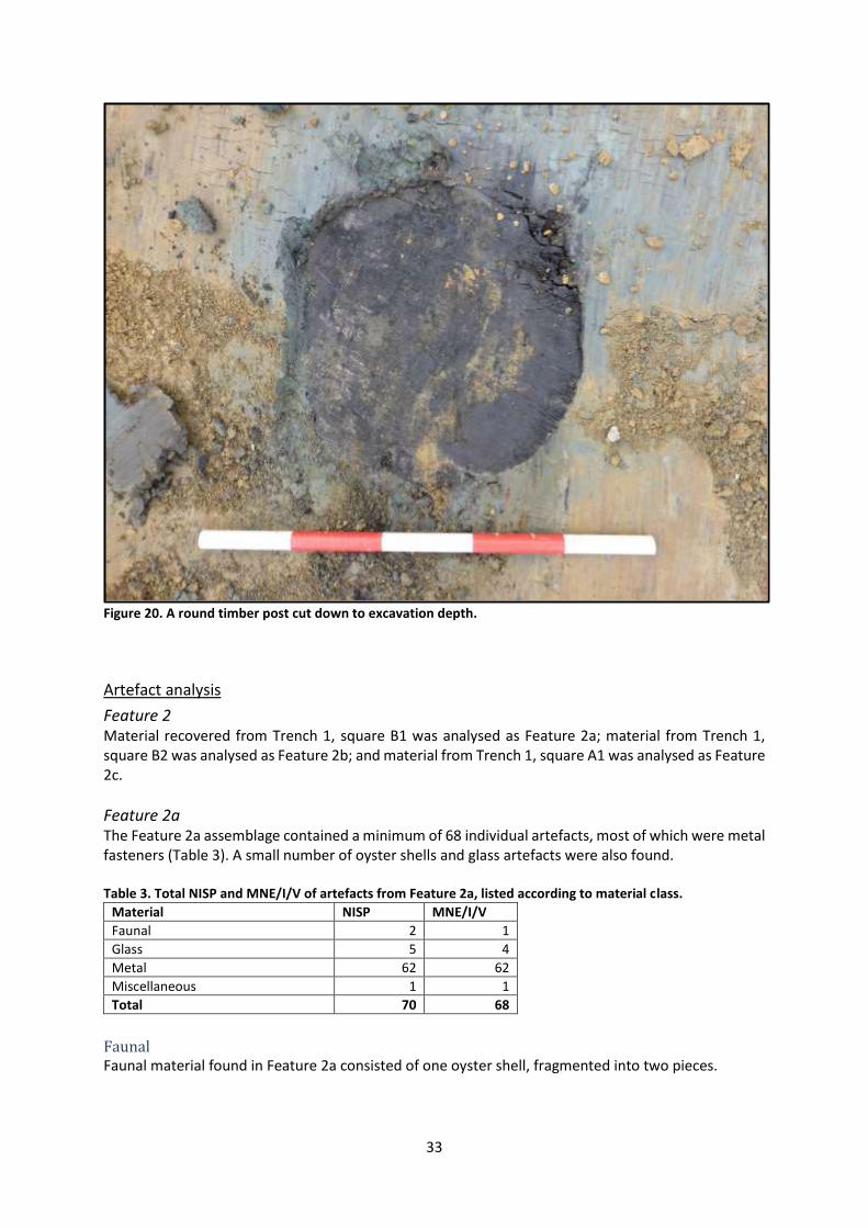
Feature 39 A round timber post was exposed at a depth of 550 mm and measured 320 mm in diameter, exposed immediately to the east of the Forbes building (Figure 20). The timber pile appeared to be driven into the surrounding fine compacted clay substrate. A timber sample was collected and determined to be mataī (Podocarpus spicatus). The post was cut down to the excavation depth of 600 mm and remains in situ.
33
Figure 20. A round timber post cut down to excavation depth.
Artefact analysis
Feature 2 Material recovered from Trench 1, square B1 was analysed as Feature 2a; material from Trench 1, square B2 was analysed as Feature 2b; and material from Trench 1, square A1 was analysed as Feature 2c.
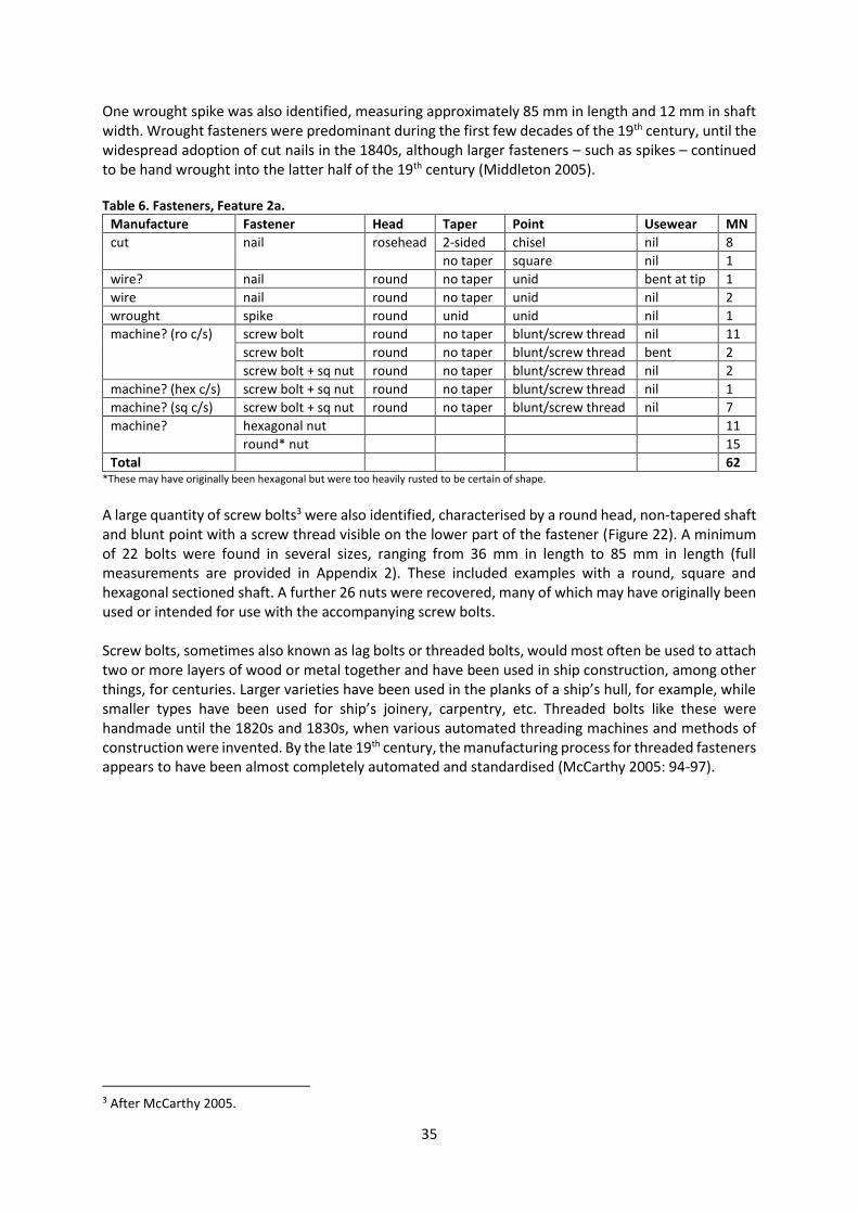
Feature 2a The Feature 2a assemblage contained a minimum of 68 individual artefacts, most of which were metal fasteners (Table 3). A small number of oyster shells and glass artefacts were also found. Table 3. Total NISP and MNE/I/V of artefacts from Feature 2a, listed according to material class.
Material NISP MNE/I/V
Faunal 2 1
Glass 5 4
Metal 62 62
Miscellaneous 1 1
Total 70 68
Faunal Faunal material found in Feature 2a consisted of one oyster shell, fragmented into two pieces.

34
Glass Four glass artefacts were also found, including fragments of two artefact bottles, window glass and one drinking vessel (Table 4 and Figure 21). One of these bottles, an amber crown top export beer, is likely to have been manufactured during the 20th century. The other three could not be dated, although all three forms have been found on both 19th and 20th century archaeological sites in New Zealand. Table 4. Glass artefacts from Feature 2a, listed according to functional class and artefact common name.
Class Common name MNV
alcohol export beer 1
ring seal wine/beer 1
structural window pane 1
table ware drinking vessel 1
Total
4
Figure 21. Glass artefacts from Feature 2a. Left to right: export beer (EQ702-G-17), ring seal wine/beer bottle (EQ702-G-18), drinking vessel (EQ702-G-19), window glass (EQ702-G-20).
Metal Metal artefacts dominated the Feature 2a assemblage, all of which were identified as fasteners (Table 5). A total of 62 individual artefacts were identified, with little to no fragmentation noted among most of them. Table 5. Metal fasteners recovered from Feature 2a, according to functional class and artefact form.
Class Form MNI
fastener screw bolt 22
nail (cut) 9
nail (wire) 1
nail (wire?) 1
screw bolt 14
spike 1
nut 26
Total
62
Several different types of fasteners were found, including bolts, nails, screws, spikes and washers (Table 6 and Figure 22). The nails identified included examples of both wire and cut manufacture. Cut and wire nails were both available in New Zealand during the 19th century: cut nails, although present on sites from the 1820s onwards, became common in the 1840s and continued to be predominant in construction until the widespread adoption of wire nails in the 1870s (Middleton 2005, Smith et al. 2014). Both cut and wire nails were in use in New Zealand outside these dates: cut nails continued to be used during the late 19th and early 20th centuries, while wire nails were first imported into New Zealand in the 1840s (Middleton 2005).
35
One wrought spike was also identified, measuring approximately 85 mm in length and 12 mm in shaft width. Wrought fasteners were predominant during the first few decades of the 19th century, until the widespread adoption of cut nails in the 1840s, although larger fasteners – such as spikes – continued to be hand wrought into the latter half of the 19th century (Middleton 2005). Table 6. Fasteners, Feature 2a.
Manufacture Fastener Head Taper Point Usewear MN
cut nail rosehead 2-sided chisel nil 8
no taper square nil 1
wire? nail round no taper unid bent at tip 1
wire nail round no taper unid nil 2
wrought spike round unid unid nil 1
machine? (ro c/s) screw bolt round no taper blunt/screw thread nil 11
screw bolt round no taper blunt/screw thread bent 2
screw bolt + sq nut round no taper blunt/screw thread nil 2
machine? (hex c/s) screw bolt + sq nut round no taper blunt/screw thread nil 1
machine? (sq c/s) screw bolt + sq nut round no taper blunt/screw thread nil 7
machine? hexagonal nut 11
round* nut 15
Total 62 *These may have originally been hexagonal but were too heavily rusted to be certain of shape.
A large quantity of screw bolts3 were also identified, characterised by a round head, non-tapered shaft and blunt point with a screw thread visible on the lower part of the fastener (Figure 22). A minimum of 22 bolts were found in several sizes, ranging from 36 mm in length to 85 mm in length (full measurements are provided in Appendix 2). These included examples with a round, square and hexagonal sectioned shaft. A further 26 nuts were recovered, many of which may have originally been used or intended for use with the accompanying screw bolts. Screw bolts, sometimes also known as lag bolts or threaded bolts, would most often be used to attach two or more layers of wood or metal together and have been used in ship construction, among other things, for centuries. Larger varieties have been used in the planks of a ship’s hull, for example, while smaller types have been used for ship’s joinery, carpentry, etc. Threaded bolts like these were handmade until the 1820s and 1830s, when various automated threading machines and methods of construction were invented. By the late 19th century, the manufacturing process for threaded fasteners appears to have been almost completely automated and standardised (McCarthy 2005: 94-97).
3 After McCarthy 2005.

36
Figure 22. Selected metal fasteners from Feature 2a. Clockwise from top left: round nuts (EQ702-M-16), hexagonal nuts (EQ702-M-17), 57 mm length square sectioned screw bolts with square nuts (EQ702-M-9), 84 mm length square sectioned screw bolt with round head and square nut (EQ702-M-7), approx. 63 mm length round sectioned screw bolts with round head and no nut (EQ702-M-18), cut rosehead nails with chisel points (EQ702-M-25), approx. 85 mm length round sectioned screw bolts with round head and no nut (EQ702-M-23), cut rosehead nail with chisel point (EQ702-M-15).

37
Feature 2b Only two artefacts were recovered from Feature 2b, identified as the body fragment from a black beer bottle of indeterminate size and a flat head copper tack, measuring 21 mm in length (Table 7 and Figure 23). Table 7. Total NISP and MNV/I of artefacts from Feature 2b, listed according to material class.
Material NISP MNV/I
Glass 1 1
Metal 1 1
Total 2 2
Figure 23. Artefacts from Feature 2b. Left: copper tack (EQ702-M-30) and right: black beer bottle glass (EQ702-G-21).
Feature 2c A small assemblage of seven metal artefacts was recovered from Feature 2c (Figure 24). These included several bolts similar to those found in Feature 2a, an unidentified wire nail and the stainless steel blade from a butter knife. The last of these, which had the mark SHEFFIELD MADE / STAINLESS / BSL, was made in the 20th century, after stainless steel was patented in 1913. B S L may refer to British Silverware Ltd, Bright Steel Ltd or another Sheffield steel/silver ware company (British Stainless Steel Association 2016, Sheffield Libraries, Archives and Information 2011).

38
Figure 24. Metal artefacts from Feature 2c. Clockwise from top left: BSL stainless steel blade (EQ702-M-35), screw bolt and nut (EQ702-M-31), short bolts (EQ702-M-34), bent wire nail (EQ702-M-35), screw bolt (EQ702-M-33).
Feature 22 Feature 22 contained five glass and ceramic artefacts, represented by nine fragments (Table 8 and Figure 25). Table 8. Total NISP and MNV of artefacts from Feature 22, listed according to material class.
Material NISP MNE/V
Ceramic 2 2
Glass 7 3
Total 9 5
The two ceramic artefacts recovered consisted of a whiteware eggcup and part of a bone china bowl, neither of which were decorated or had any manufacturer’s marks present. The three glass artefacts included a black beer bottle, an unidentified condiment bottle and fragments of an unidentified hollow-ware vessel made from turquoise coloured glass. No identifying marks were noted.
Figure 25. Artefacts from Feature 22. Left to right: eggcup base (EQ702-C-22), bone china bowl (EQ702-C-23), black beer bottle base (EQ702-G-11), unidentified turquoise glass vessel (EQ702-G-13), unidentified condiment bottle (EQ702-G-12).
39
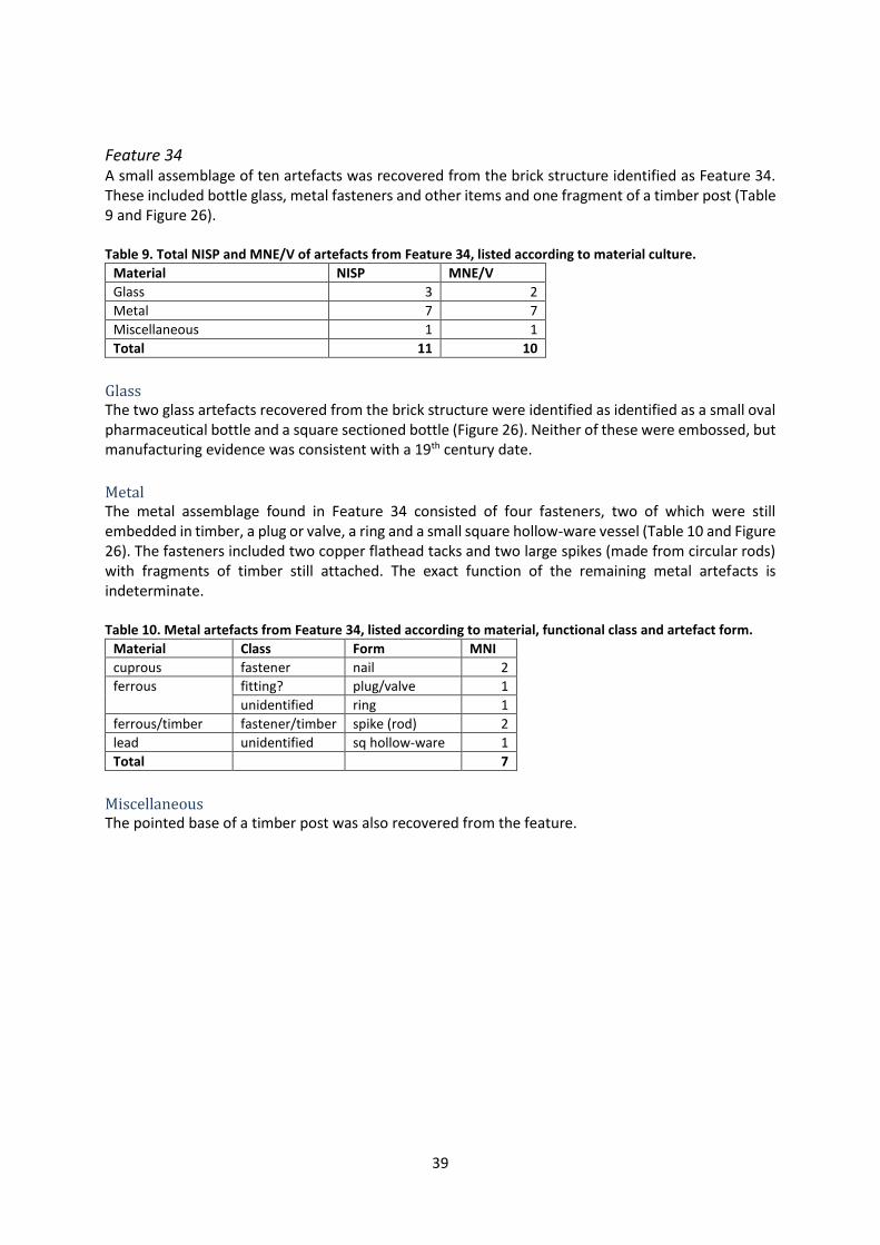
Feature 34 A small assemblage of ten artefacts was recovered from the brick structure identified as Feature 34. These included bottle glass, metal fasteners and other items and one fragment of a timber post (Table 9 and Figure 26). Table 9. Total NISP and MNE/V of artefacts from Feature 34, listed according to material culture.
Material NISP MNE/V
Glass 3 2
Metal 7 7
Miscellaneous 1 1
Total 11 10
Glass The two glass artefacts recovered from the brick structure were identified as identified as a small oval pharmaceutical bottle and a square sectioned bottle (Figure 26). Neither of these were embossed, but manufacturing evidence was consistent with a 19th century date.
Metal The metal assemblage found in Feature 34 consisted of four fasteners, two of which were still embedded in timber, a plug or valve, a ring and a small square hollow-ware vessel (Table 10 and Figure 26). The fasteners included two copper flathead tacks and two large spikes (made from circular rods) with fragments of timber still attached. The exact function of the remaining metal artefacts is indeterminate. Table 10. Metal artefacts from Feature 34, listed according to material, functional class and artefact form.
Material Class Form MNI
cuprous fastener nail 2
ferrous fitting? plug/valve 1
unidentified ring 1
ferrous/timber fastener/timber spike (rod) 2
lead unidentified sq hollow-ware 1
Total
7
Miscellaneous The pointed base of a timber post was also recovered from the feature.

40
Figure 26. Artefacts from Feature 34. Clockwise from top left: square sectioned bottle (EQ702-G-23), oval pharmaceutical bottle (EQ702-G-22), plug or valve (EQ702-M-42), part of a ring (EQ702-M-41), copper based square hollow-ware vessel (EQ702-M-40), copper tack (EQ702-M-38), timber post (EQ702-MC-2), spike and timber (EQ702-M-43), spike and timber (EQ702-M-44).
Feature 36 A relatively large assemblage of artefacts was recovered from Feature 36, consisting of 74 individual items represented by 174 fragments. These were predominantly glass, although ceramic and other artefacts were also found (Table 11 and Figure 27). Table 11. Total NISP and MN of artefacts recovered from Feature 36, listed according to material class.
Material NISP MNE/V
Ceramic 8 3
Glass 165 70
Miscellaneous 1 0*
Total 174 73 *MNV of 0, as artefact is likely to belong with one of the other vessels recovered from the feature.

41
Ceramic The three ceramic artefacts found in Feature 36 were identified as a serving dish, a bowl or chamber pot and a fragment of unidentified hollow-ware (Table 12 and Figure 27). The last of these may have been a teacup, but the size of the fragment made it difficult to know for certain. All of these vessels were whiteware. The serving dish and the unidentified hollow-ware vessels were both decorated: the former with a transfer print of the Willow pattern and the latter with an unidentified flown blue foliage motif. Table 12. Ceramic artefacts from Feature 36, listed according to body type, ware type, functional class and artefact form.
Body Type Ware Function Form MNI
ew-r ww table ware serving dish 1
table ware/household bowl/chamber pot 1
unidentified unid hollow-ware 1
Total
3
Figure 27. Ceramic artefacts from Feature 36. Left to right: bowl/chamber pot (EQ629-C-2), Willow patterned serving dish (EQ629-C-3), flown blue foliage patterned hollow-ware (EQ629-C-3).
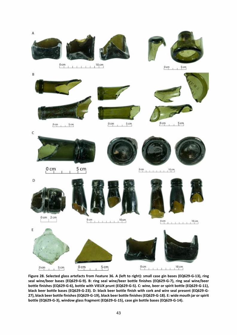
Glass Glass artefacts comprised the majority of the Feature 36 assemblage, with a minimum of 70 individual artefacts identified. These were predominantly alcohol bottles, although one possible food related artefact and several fragments of window glass were also recovered (Table 13 and Figure 28). Alcohol bottles consisted of a variety of forms and sizes, from black beer bottles and case gin bottles to ring seal wine/beer bottles and spirit bottles. Several sizes were represented among the black beer bottles, including the larger ‘quart’ size (known as large squat or large tall, measuring 88 mm + and 75-88 mm in base diameter), and the smaller ‘pint’ size (small or small squat, measuring 60-70 mm and 75-85 mm base diameter). Case gins were also found in small and large sizes (measuring 60 mm and 71 mm in base width). Such differences in bottle size correspond directly to the quantities in which beer and spirits were sold, both wholesale and in a retail context (Illinois Glass Catalogue 1906: 250, Lindsey 2016). Newspaper advertisements from the 1870s and 1880s suggest that quarts of beer sold for approximately 6-9 pence per bottle, depending on the variety of beer, the quantity purchased and the place wherein it was sold. Pint bottles appear to have cost roughly half that of quarts (Evening Post 8/6/1871: 3, 10/5/1880:4).

42
Table 13. Glass artefacts from Feature 36, listed according to functional class and artefact form.
Class Common name MNV
alcohol black beer (l or ss) 9
black beer (ls) 35
black beer (s) 2
case gin (large) 8
case gin (small) 3
ring seal wine/beer (large) 3
ring seal wine/beer (medium) 3
spirit bottle 1
wine beer or spirit 1
wine or beer 1
wine, beer or spirit bottle 1
wine/beer 1
alcohol/food wide mouth pickle jar or spirit bottle 1
structural window glass 1
Total
70
Alcohol bottles like these, while primarily associated with the consumption of alcoholic beverages such as beer, wine, whisky, gin and rum, may have been used to hold a variety of other products during prior to being discarded. Bottle reuse has been well documented archaeologically, and several examples of this phenomenon have been found in Christchurch to date. Many of the bottles had crude applied finishes and/or asymmetric bases, suggesting that they may have been manufactured in the mid-late 19th century. Only four bottles were embossed: three case gins had a cross on the base of the bottle, while one of the wine/beer bottles had VIEUX / … AC embossed in a glass blob seal or ‘prunt’ on the shoulder. The latter, while unidentified, may indicate the bottle was originally of French manufacture or was initially used to hold a French product.
Miscellaneous One other artefact was recovered from Feature 36, identified as a bottle cork. This is likely to have originally been associated with one of the bottles recovered.
43
Figure 28. Selected glass artefacts from Feature 36. A (left to right): small case gin bases (EQ629-G-13), ring seal wine/beer bases (EQ629-G-9). B: ring seal wine/beer bottle finishes (EQ629-G-7), ring seal wine/beer bottle finishes (EQ629-G-6), bottle with VIEUX prunt (EQ629-G-5). C: wine, beer or spirit bottle (EQ629-G-11), black beer bottle bases (EQ629-G-23). D: black beer bottle finish with cork and wire seal present (EQ629-G-27), black beer bottle finishes (EQ629-G-19), black beer bottle finishes (EQ629-G-18). E: wide mouth jar or spirit bottle (EQ629-G-3), window glass fragment (EQ629-G-15), case gin bottle bases (EQ629-G-14).

44
Discussion
The remains of the Forbes building found during these earthworks included the east foundation wall, two sandstone foundation blocks, a sump, a second brick feature and some timber flooring. A slate-lined drain had been constructed on the southeast corner of the building, presumably to carry water away from the building. Two posts were found further to the east, and their association with the building cannot be confirmed. While the two timber posts were left in situ, the depth of earthworks for this project mean that it is unlikely that any other features associated with the building remain. Artefacts were recovered from a number of features associated with the building, including from a rubbish pit immediately to the east, and possibly deposited by the occupants of the building. The Feature 2 assemblage is likely to have been deposited in the early 20th century, due to the presence of a crown top amber bottle and 1913+ stainless steel blade. The screw-bolts found in the feature, however, may have been used or intended for use in the construction of ships or ships’ joinery during the 19th and early 20th centuries. The assemblage recovered from the fill overlying Feature 34 contained no artefacts able to be dated to a specific period, although manufacturing evidence is consistent with 19th century artefacts found elsewhere in Christchurch. They cannot have been deposited prior to the construction of the brick structure identified as Feature 34. It is likely that they are redeposited or may represent the surface accumulation of artefacts over time: in either case, they are unlikely to be associated with the function of Feature 34. Feature 36, was dominated by alcohol bottles, including a high proportion of black beer and case gin bottles. The predominance of these artefacts, when coupled with the evidence for crude manufacture noted on the bottles, would suggest a date of manufacture and discard from the 1850s-1880s, although it is possible that they were used and discarded outside of these dates. These bottles may have been associated with Forbes building, which was used as a warehouse and bonded store from 1863 onwards. They may represent discarded or broken stock from the store or, alternatively, have been used by those who built or worked in the store during this period. It is worth noting that no evidence of burning was noted among the artefact assemblage from Feature 36, suggesting that it was not associated with the fire recorded at the site in 1884.
M36/229: ŌHINEHOU
Historical background
In 2012, following the Canterbury earthquakes of 2011, the former Lyttelton post office building at 7 Norwich Quay was demolished. Amongst other things, removal of the foundations revealed the remains of a pre-contact Māori oven and midden deposits (Dodd and Watson 2012). This work was significant for providing physical evidence of Māori occupation in this area, and insights into the fishing and subsistence activities that took place there. A rich variety of food waste was recovered from the site, including the following shellfish: catseye, pāua, Bluff oyster, blue mussel, silver pāua, turret shell, green lipped mussel, mud snail, pipi, speckled whelk, white rock shell and venus shell. Fish species included shark/ray, red cod, kahawai and ling. Bird species included little shag, spotted shag, tui, New Zealand wood pigeon, blue penguin, moa bone, New Zealand falcon, parakeet, moa, tui, kiwi and other unidentified species. The mammal remains included rat and dog bone. One of the features exposed during this work returned a radiocarbon date of AD 1465-1660 at 95% confidence.4 In addition, a small
4 For a full discussion of this site, see Dodd & Watson 2012

45
broken adze was found at the site. This site is significant for its association with Māori occupation of the area and for the information about that occupation that it has revealed.
Results of archaeological monitoring
Due to the significance of this area, a representative from Te Hapū o Ngāti Wheke was present during all earthworks here. No artefacts or features relating to this archaeological site were exposed during earthworks, largely due to the shallow nature of the earthworks.
M36/293: ERSKINE BAY SEAWALL
Historical background
In 1849-50 the Canterbury Association erected a seawall east to west across Erskine Bay, in conjunction with the government wharf that extended into the harbour from the end of Oxford Street (Rice 2004:26; Figure 32). The seawall was used as a berthing place and for landing small goods (Lyttelton Times 12/4/1851:2). A severe southwest gale in June 1851 damaged the sea wall and tenders for repairs and additions to the sea wall were invited from carpenters and masons in July 1851 (Lyttelton Times 12/7/1851:1, Plowman 1941:39). Part of the seawall was rebuilt in 1852, authorised by the Canterbury Association who invited tenders from masons (Lyttelton Times 26/6/1852:1). The contract was let to Lyttelton stonemason William Chaney, indicating that a section of the wall was rebuilt in stone. The alignment of the seawall is indicated by comparison of Captain Thomas’ 1849 plan of Lyttelton harbour with a plan of the Lyttelton reserves from 1853 (Figure 29 and Figure 30). Its form extending either side of the Oxford Street jetty is seen in a photograph taken by Daniel Louis Mundy in 1867 (Figure 31). The wall reclaimed land south of Norwich Quay, which was incorporated into Reserve 32, leased by the Canterbury Association to Augustus James Alport in 1855 (LINZ c.1850: 632; Figure 30). Alport had previously worked with Captain Thomas on preparing the port for the arrival of Canterbury Association vessels and acted as an agent for the Canterbury Association (Macdonald n.d.: A142). Alport sub-let the land from 1860. He left Lyttelton around 1863 and his lease transferred to Alfred Richard Creyke (LINZ c.1850: 632; Lyttelton Times 26/9/1863:6).
Figure 29. Detail from “Plan of Lyttelton, Port Victoria”, September 1849, J. Thomas surveyor. Image: Archives New Zealand: ref. CH1031-180/297.

46
Figure 30. Detail from “Association reserves at port Lyttelton and Sumner”, 1853-64 (Provincial Council. Ordinances, Session IV, no. 6, 1855). Probable seawall at southern boundary of Reserve 32.
Figure 31. Detail from photograph of Lyttelton, 1867. D. L. Mundy photograph (Alexander Turnbull Library: ref. Mundy album 2, PA1-f-040).
Results of archaeological monitoring
The archaeological monitoring revealed a number of posts and timbers associated with the seawall (Figure 32).
Sea wall (1849)
Hargreaves store (1864)
Forbes building (1863)
Railway reclamation, incomplete (1867)
Former location of “Forbes’ jetty”

47
Figure 32. Historic footprint of the Erskine Bay seawall shown with red line.

48
Feature 14 Five timber posts were exposed at a depth of 250 mm during resurfacing earthworks (Figure 33). The timber posts were rectangular in shape and measured between 150 and 250 mm in length by 150 mm in width. All posts were exposed in a clay and stone mixed layer. The timbers were a deep red colour. The posts were left in situ.
Figure 33. A post showing the deep red colour.
Feature 23 Six wooden posts and one timber cross beam/board were exposed at a depth between 250 and 500 mm in the surrounding compacted clay layer (Figure 34 and Figure 35). The posts and board were orientated northwest-southeast and spaced 1250 mm apart. The timber posts were labelled alphabetically from west to east (A, B, C, D, E and F). The connecting cross-board was labelled G and connected timber posts C and D. Timber samples were collected from C, D and G. The timber sample results show C and D were both tōtara (Podocarpus totara) and G is mataī (Podocarpus spicatus). The timber posts and cross board remain in situ. As such, the feature was not drawn in detail.

49
Figure 34. Post D (left), cross-board G (centre) and post C (right).
50
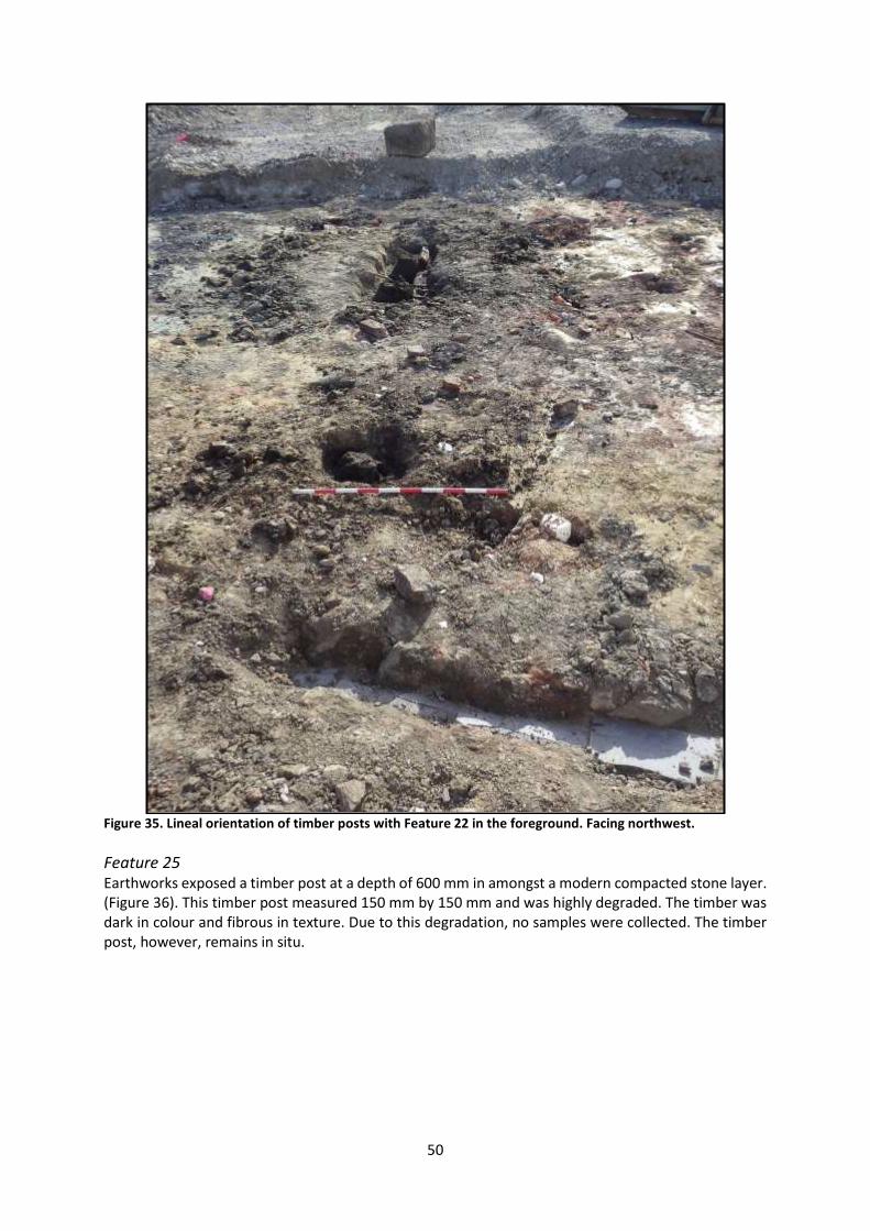
Figure 35. Lineal orientation of timber posts with Feature 22 in the foreground. Facing northwest.
Feature 25 Earthworks exposed a timber post at a depth of 600 mm in amongst a modern compacted stone layer. (Figure 36). This timber post measured 150 mm by 150 mm and was highly degraded. The timber was dark in colour and fibrous in texture. Due to this degradation, no samples were collected. The timber post, however, remains in situ.
51
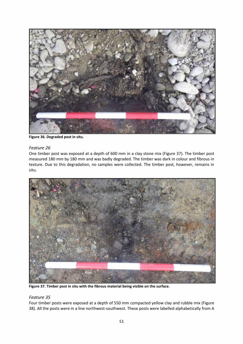
Figure 36. Degraded post in situ.
Feature 26 One timber post was exposed at a depth of 600 mm in a clay stone mix (Figure 37). The timber post measured 180 mm by 180 mm and was badly degraded. The timber was dark in colour and fibrous in texture. Due to this degradation, no samples were collected. The timber post, however, remains in situ.
Figure 37. Timber post in situ with the fibrous material being visible on the surface.
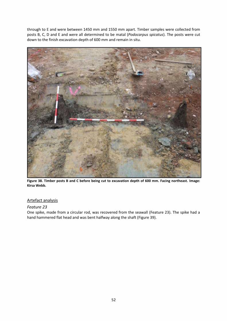
Feature 35 Four timber posts were exposed at a depth of 550 mm compacted yellow clay and rubble mix (Figure 38). All the posts were in a line northwest-southwest. These posts were labelled alphabetically from A
52
through to E and were between 1450 mm and 1550 mm apart. Timber samples were collected from posts B, C, D and E and were all determined to be mataī (Podocarpus spicatus). The posts were cut down to the finish excavation depth of 600 mm and remain in situ.
Figure 38. Timber posts B and C before being cut to excavation depth of 600 mm. Facing northeast. Image: Kirsa Webb.
Artefact analysis
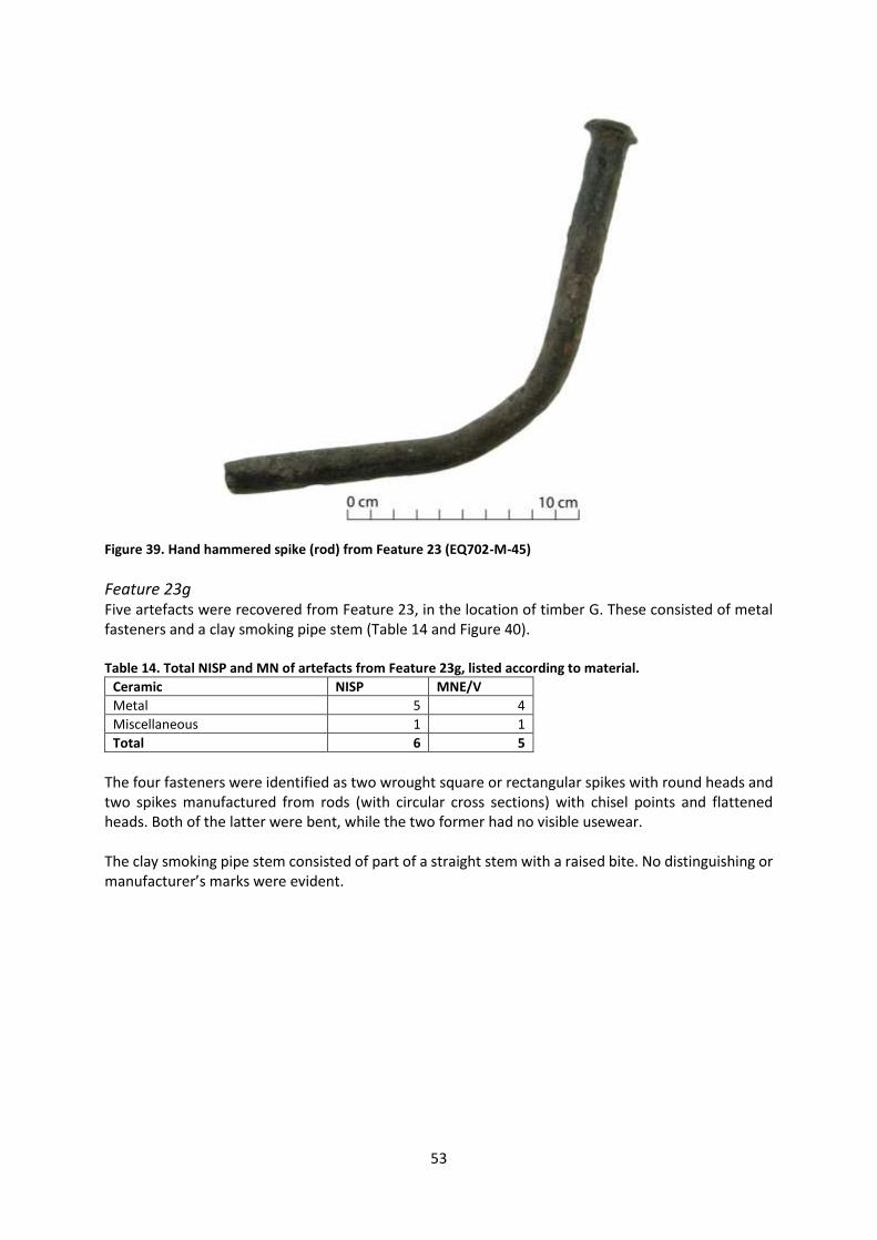
Feature 23 One spike, made from a circular rod, was recovered from the seawall (Feature 23). The spike had a hand hammered flat head and was bent halfway along the shaft (Figure 39).
53
Figure 39. Hand hammered spike (rod) from Feature 23 (EQ702-M-45)
Feature 23g Five artefacts were recovered from Feature 23, in the location of timber G. These consisted of metal fasteners and a clay smoking pipe stem (Table 14 and Figure 40). Table 14. Total NISP and MN of artefacts from Feature 23g, listed according to material.
Ceramic NISP MNE/V
Metal 5 4
Miscellaneous 1 1
Total 6 5
The four fasteners were identified as two wrought square or rectangular spikes with round heads and two spikes manufactured from rods (with circular cross sections) with chisel points and flattened heads. Both of the latter were bent, while the two former had no visible usewear. The clay smoking pipe stem consisted of part of a straight stem with a raised bite. No distinguishing or manufacturer’s marks were evident.

54
Figure 40. Artefacts from Feature 23g. Clockwise from top left: spikes made from circular rods (EQ702-M-3), wrought spike with chisel point (EQ702-M-4), clay smoking pipe stem with raised bite (EQ702-S-3), wrought spike with square cross section (EQ702-M-5).
Feature 35b Feature 35b (Timber B in Feature 35) yielded one artefact, identified as a spike (made from a circular rod; Figure 41). This had been bent.
Feature 35c Two artefacts were found in association with Timber C in Feature 35 (Figure 41). These consisted of a complete stoneware penny ink bottle and a wrought and clenched nail still embedded in timber fragments. Clenching, identified through a sharp bend in the shaft of the fastener, indicates that the nail was hammered over at an angle to tighten its grip during use. The penny ink bottle was unmarked, but these bottles are frequently found on 19th century archaeological sites in Christchurch and were so named due to the original cost of the bottles.
Feature 35d Fragments of a whiteware dinner plate decorated with the Country Scenery transfer print were found in association with Feature 35d (Figure 41). This pattern is known to have been made by Lockhart and Arthur and the subsequent firm of David Lockhart and Co., operating from 1855-1864 and 1865-1898 in Glasgow, although no accompanying maker’s mark was present on these fragments (Transferware Collector’s Club 2016; Godden 1991: 394-395).

55
Figure 41. Artefacts from Feature 35b, Feature 35c and Feature 35d. Clockwise from top: spike (made from a rod) (EQ702-M-2), wrought nail with timber attached (EQ702-M-1), penny ink bottle (EQ702-C-24), Country Scenery plate (EQ702-C-25).
Discussion
A number of features of piles and boards in a lineal pattern with heavy fasteners were exposed during earthworks. These features are likely to be remnants of the Erskine Bay seawall. Timber samples indicate that both tōtara and mataī were used in the construction of this wall. Artefacts recovered from these features also provide evidence of the construction techniques used for the seawall, including the use of rod spikes. Other material found is likely to have been surface accumulation or redeposited fill material of unknown date. While the full extent of the wall is unknown, the wall remains in situ for future study.
M36/299: HEYWOOD’S JETTY/HEYWOOD’S AND FORBE’S JETTY
Historical background
A small jetty servicing the warehouse formerly situated at 17 Norwich Quay was probably built in the 1850s, but was lost in the land reclamation for the railway in the mid-1860s (Figure 31). The jetty is known in the historical record as ‘Heywood’s jetty’ or ‘Heywood and Forbes’ jetty’, but is unlikely to be associated with either Heywood or Forbes (Rice 2004:28-29). The jetty was probably built by Alport who applied to the Canterbury Provincial Government in 1855 to erect a jetty on the land he leased on Reserve 32 from 1855 (Archives New Zealand 1855, LINZ c.1850: 632, Press 5/5/1870: 2). In 1863 a jetty, presumably the one built by Alport, was situated at the southwest corner of the warehouse occupied by Hall, Ritchie and Co., later the site of Forbes’ building (Lyttelton Times 21/2/1863:4). After the lease on the land and building transferred to Louisson in 1866 the jetty was known as ‘Louisson’s jetty’ but had been removed before 1870 (Press 5/5/1870:2).

56
Results of archaeological monitoring
Although a number of features were found within the footprint of the jetty, only one is believed to have been associated with it (Figure 42). The other features included a rubbish pit (Feature 24) and a 20th century feature (Feature 27).
Figure 42. Historic footprint of Heywood’s jetty/Heywood’s and Forbe’s jetty shown in grey.

57
Feature 30 One timber post was exposed at a depth of 600 mm in a clay and rubble mix layer, within the footprint of the jetty (Figure 43). The post measured 350 mm by 350 mm and was very degraded on the surface. Further excavation was not required as the contractors had reached the depth necessary for the project. As a result of the degradation, no timber samples were collected. The timber post, however, was similar in texture and colour to Feature 23 (associated with the Erskine Bay sea wall). The post remains in situ.
Figure 43. Timber post exposed at a depth of 600 mm. The pipe to the right dated to the 20th century and was not recorded or mapped.
Discussion
A timber pile was exposed to the south of the possible timber seawall and in the vicinity of the jetty recorded as archaeological site M36/299. It is possible that this post is associated with that jetty. Further excavation in the area of Feature 30 will reveal if there are any associated jetty piles.
M36/300: HARGREAVES’ STORE
Historical background
Edward Allen Hargreaves, a merchant and representative for Lyttelton on the Canterbury Provincial Council, built a three-storey stone store on the waterfront in 1864 (Lyttelton Times 30/5/1863:7). The building, designed by architect and surveyor Charles E. Fooks, experienced a slow and protracted build process due to the failure of the first contractor (Lyttelton Times 12/7/1864:3). Hargreaves’ warehouse was completed by the end of 1864 and was described as a “conspicuous object in the town from the seaward” (Lyttelton Times 15/11/1864:4). The building had three storeys on the waterfront side and two storeys facing Norwich Quay. It was built of Governors Bay tufa and freestone quarried at Quail Island with interior walls from red scoria quarried on the Sumner Road. The timber was blue gum imported from Hobart, Tasmania. The building measured 80 feet (24.38 metres) in length and 50 feet (15.24 metres), and accommodated a bonding store and free store (Lyttelton Times 15/11/1864:4).
58
The foundations of the building were laid in the “old beach” to a depth of 11 feet 6 inches (3.50 metres; Press 5 May 1870:2). Hargreaves relocated from his former premises, on the opposite side of Norwich Quay, to his new store by June 1865 (Press 30/6/1865:1). However, the opening of Hargreaves’ store coincided with the Provincial Government’s works to link the railway with the port. In 1865 the Provincial Government let a contract for the construction of a new sea wall in advance of reclamation of land for the Lyttelton Railway Station (Press 23/2/1865:2, Lyttelton Times 13/5/1865:6, Press 20/2/1867:1). The construction of the sea wall in 1866 cut off Hargreaves’ store from the waterfront, rendering it useless for offloading goods (Press 7/5/1870:2). The sea wall not only decreased the value of the building, but the method of construction of the sea wall caused water to accumulate around the foundations of Hargreaves’ store (Press 5/5/1870:2). Following a heavy storm in July 1867 architect S. C. Farr inspected the building and found it to be severely damaged by “the action of the water in a pool formed by filling in at the back of the sea-wall”. The water had soaked the earth around the foundation causing settlement, particularly at the seaward side. Walls had bulged and fractured, floors had sunk, arches were displaced and the building was found in a generally dangerous state and at risk of collapse (Press 5/5/1870:2). Hargreaves complaint to the Provincial Government remained unresolved until May 1870 when it was heard by the Sheriff’s Court. The jury found in favour of Hargreaves and the Provincial Government was made to compensate him £1,700 for loss in value of his building and the damage caused by construction of the sea wall (Press 4/5/1870:2, 5/5/1870:2, 7/5/1870:2, Star 6/5/1870:2). Hargreaves’ store was not immediately demolished and survived the Lyttelton fire of 25 October 1870 (Star 26/10/1870:2). The building was used to house goods saved from the fire and served as temporary premises for displaced businesses and services (Star 31/10/1870:3, Press 15/11/1870:2, Star 27/8/1872:1, 18/4/1874:4). Hargreaves’ lease transferred to land agent Collier and Co. in February 1870 and eventually passed to Peter Cunningham who, in 1881, surrendered the site to the Provincial Government for the construction of a Sailors’ Home (LINZ c.1850:632, Star 4/11/1881:4). Construction of the Sailors’ Home began in January 1883 and it was completed in December that year (Press 23/1/1883:2, Star 5/12/1883:4). The Sailors’ Home was a three storey building constructed in concrete on the lower level and brick on the upper two storeys. It stood until 1970 when it was demolished (Beaumont et al. 2014: 381).
Results of archaeological monitoring
No artefacts or features relating to this archaeological site were exposed during earthworks, which extended to a depth of 600 mm (Figure 44). Onsite monitoring was employed when excavations took place in the vicinity of this area. It is possible that building foundations and related rubbish deposits remain in situ at a greater depth.

59
Figure 44. The historic footprint of Hargreaves’ store is shown in grey.
60
M36/302: RAIL RECLAMATION, NORTHERN RECLAMATION
Historical background
In 1864 Provincial Engineer Edward Dobson reported to the Provincial Government on a plan for the railway terminus at Lyttelton. Dobson’s report was principally concerned with providing sufficient wharfage to connect the railway with the port and to overcome the shallowness of the water in Erskine Bay, the easterly swell and southwest gale (Lyttelton Times 20/8/1864:3). The final plan included the construction of two moles (or breakwaters), constructing a stone embankment from Officers’ Point to the “existing railway embankment”, reclamation of land between Norwich Quay and the new stone embankment, extension of the existing Oxford Street wharf and construction of a new wharf (Lyttelton Times 20/8/1864:3; Figure 45). The land for the railway terminus was reclaimed by building a seawall and filling the space between the wall and Norwich Quay. In February 1865 the Secretary of Public Works invited tenders from contractors for construction of a 700 feet (213 metre) sea wall in front of the site of the Lyttelton Railway Station (Press 23/2/1865:2). The contract was awarded to E. G. Wright in May 1865 (Lyttelton Times 13/5/1865:6). The sea wall was not a stone embankment as Dobson had originally recommended, but was constructed from timber framing with stone backing and clay filling behind (Canterbury Provincial Government 1867:148, 154-155). The wall was intended for completion in March 1866, but was delayed due to late delivery of the timber required (Canterbury Provincial Government 1867:148). The unfinished structure was exposed to the weather and the sea, causing part of the stone and timber structure to collapse (Canterbury Provincial Government 1867:154). Further, the shifting mud at the bed of the harbour caused prominent bulges in the wall (Lyttelton Times 7/1/1867:3, Scotter 1968:74-75). In response to this failure, Dobson altered the design “giving the stone backing a wider base, and driving the sheet piling down to a greater depth” (Canterbury Provincial Government 1867:154). He also recommended that once the wall had settled in position an additional row of “iron bark piles” be driven in front of the wall. The work was expected to be completed by the end of 1866. However, by February 1867 a “cesspool” had formed between the sea wall and Norwich Quay and Lyttelton residents called for it to be immediately filled (Lyttelton Times 20/2/1867:2). In February 1867 tenders were invited for “72,000 cubic yards [55,048 cubic metres] of Embankment for the reclamation of the space between Norwich quay and the Sea-wall” (Press 20/2/1867:1). James. M. Balfour, Dobson’s successor, specified that the land be filled in by constructing a causeway of rubble behind the sea wall and another parallel causeway thirty feet inland from it. Balfour specified that these causeways be constructed of “clay merely faced with stone”. From these “roadways” the “earth” should be tipped towards the land then left to settle and finally filled with “rubble” (Press 9/4/1867:2). It has been presumed that the fill for the reclamation was from material excavated from the railway tunnel, and this was apparently the intention of the Canterbury Provincial Government (Lyttelton Times 8/6/1865:4, Rice 2004:35, Scotter 1968:75). Dobson did not specify this in his proposal and the documentary record contains conflicting evidence in this regard. The contract for the tunnel excavation did not secure the Provincial Council’s ownership of the spoil, and so this was not available for use in land reclamation (Lyttelton Times 11/4/1867:2). The contractors for the tunnel excavation, George Holmes and Co., tendered for the railway reclamation work, but their estimate was “extravagant” considering their access to spoil from tunnel excavation (Lyttelton Times 11/4/1867:2). An alternative tender was accepted, presumably from E. G. Wright, who sourced stone quarried from “the other side of the harbour” for the purpose (Lyttelton Times 11/4/1867:2). However, following completion of the tunnel contract, Holmes and Co. filed a claim against the Provincial Government for unpaid work in “filling up a large and valuable piece of land with material from the tunnel by direction of the Engineer from time to time” (Lyttelton Times 28/11/1868:2). Holmes and Co. claimed payment
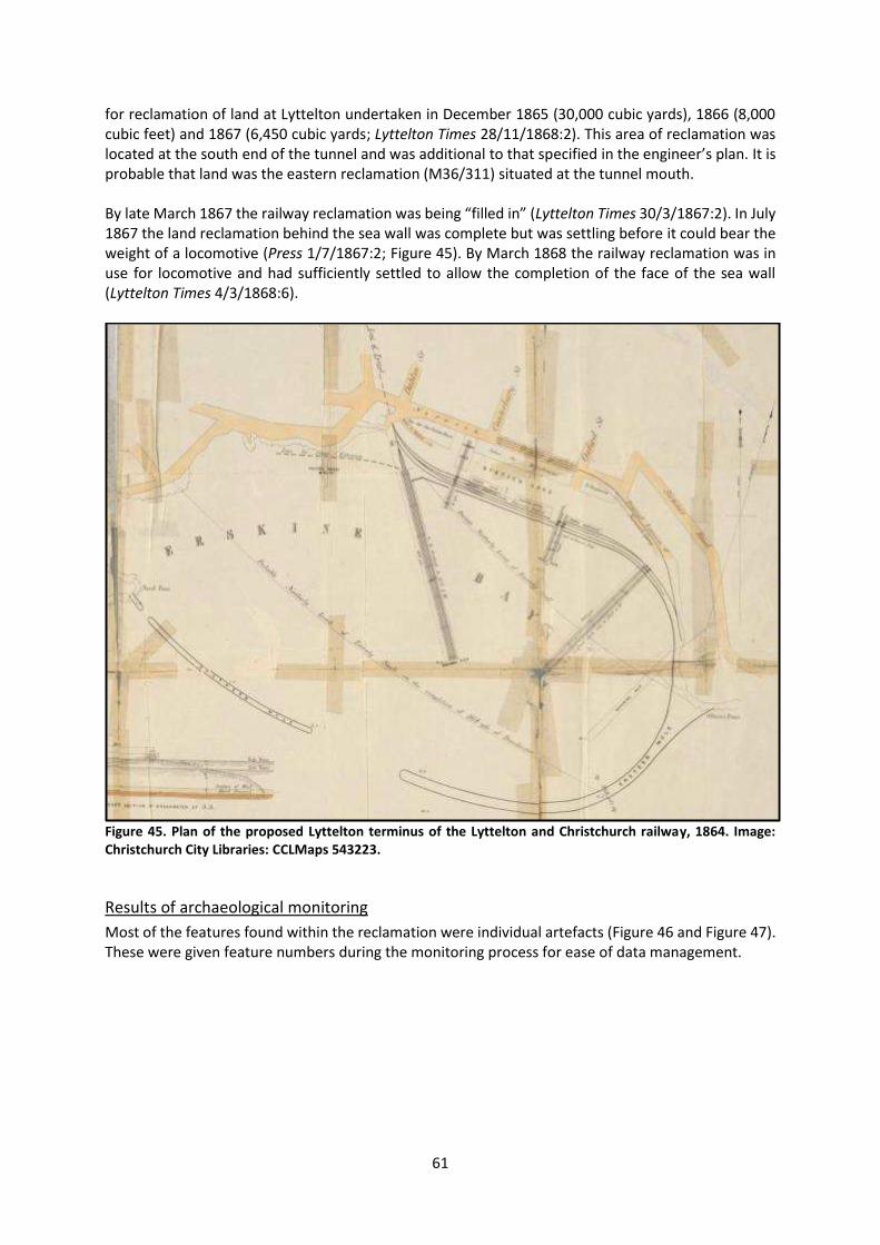
61
for reclamation of land at Lyttelton undertaken in December 1865 (30,000 cubic yards), 1866 (8,000 cubic feet) and 1867 (6,450 cubic yards; Lyttelton Times 28/11/1868:2). This area of reclamation was located at the south end of the tunnel and was additional to that specified in the engineer’s plan. It is probable that land was the eastern reclamation (M36/311) situated at the tunnel mouth. By late March 1867 the railway reclamation was being “filled in” (Lyttelton Times 30/3/1867:2). In July 1867 the land reclamation behind the sea wall was complete but was settling before it could bear the weight of a locomotive (Press 1/7/1867:2; Figure 45). By March 1868 the railway reclamation was in use for locomotive and had sufficiently settled to allow the completion of the face of the sea wall (Lyttelton Times 4/3/1868:6).
Figure 45. Plan of the proposed Lyttelton terminus of the Lyttelton and Christchurch railway, 1864. Image: Christchurch City Libraries: CCLMaps 543223.
Results of archaeological monitoring
Most of the features found within the reclamation were individual artefacts (Figure 46 and Figure 47). These were given feature numbers during the monitoring process for ease of data management.

62
Figure 46. Footprint of 19th century reclamation shown as shaded area with diagonal lines. Stage 1.
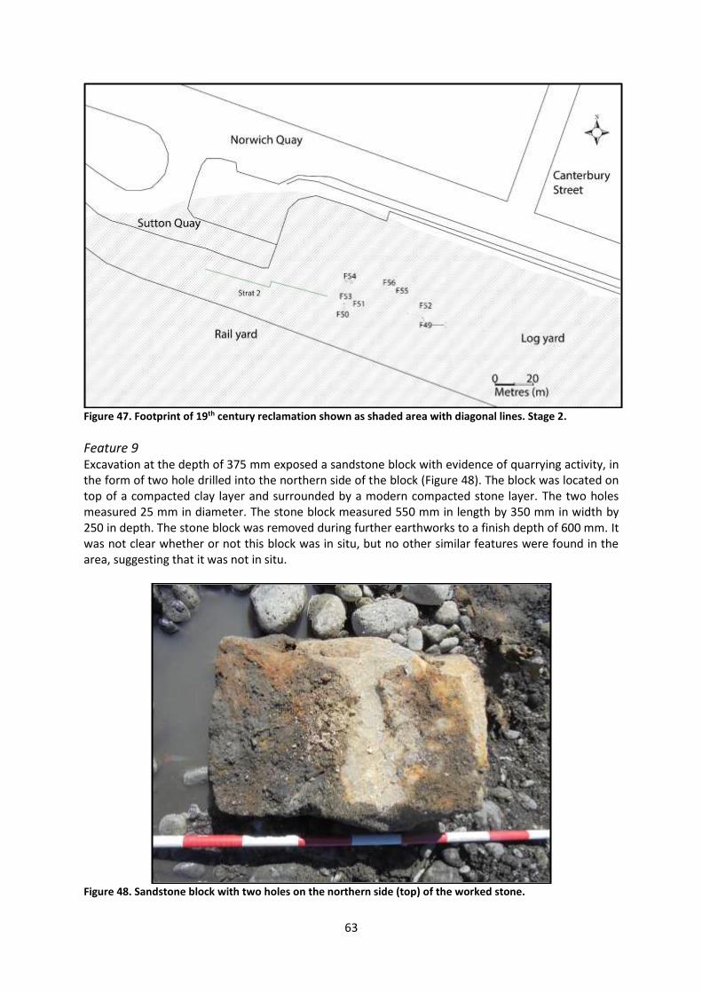
63
Figure 47. Footprint of 19th century reclamation shown as shaded area with diagonal lines. Stage 2.
Feature 9 Excavation at the depth of 375 mm exposed a sandstone block with evidence of quarrying activity, in the form of two hole drilled into the northern side of the block (Figure 48). The block was located on top of a compacted clay layer and surrounded by a modern compacted stone layer. The two holes measured 25 mm in diameter. The stone block measured 550 mm in length by 350 mm in width by 250 in depth. The stone block was removed during further earthworks to a finish depth of 600 mm. It was not clear whether or not this block was in situ, but no other similar features were found in the area, suggesting that it was not in situ.
Figure 48. Sandstone block with two holes on the northern side (top) of the worked stone.

64
Feature 11 A leather boot was exposed at a depth of 1650 mm amongst a blue pug clay layer during drainage works (Figure 49). It was located in a blue pug clay layer. The boot was an isolated find and was recovered for analysis by an artefact specialist (see the artefact analysis section).
Figure 49. Leather boot in situ with the sole disturbed by the mechanical excavator. Facing north.
Feature 12 A timber was exposed at a depth of 1000 mm during stage 1 excavation works for a new drainage trench (Figure 50). This timber was exposed in a blue pug clay layer. The timber resembled a hard wood and was dark red in colour. The timber measured 905 mm in length by 105 mm in width by 150 mm in depth. The timber was an isolated find and was not associated with any other timber structure. Due to the lack of context, no further analysis was undertaken or sampled retained.
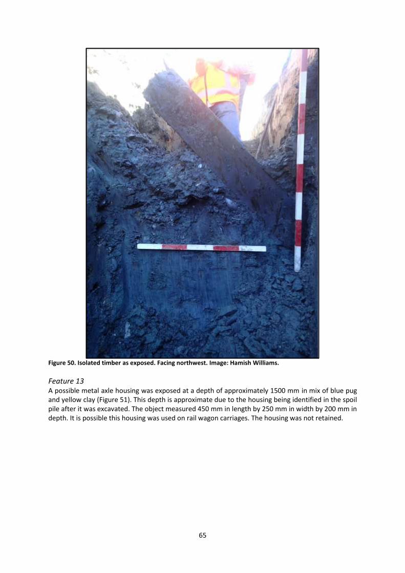
65
Figure 50. Isolated timber as exposed. Facing northwest. Image: Hamish Williams.
Feature 13 A possible metal axle housing was exposed at a depth of approximately 1500 mm in mix of blue pug and yellow clay (Figure 51). This depth is approximate due to the housing being identified in the spoil pile after it was excavated. The object measured 450 mm in length by 250 mm in width by 200 mm in depth. It is possible this housing was used on rail wagon carriages. The housing was not retained.
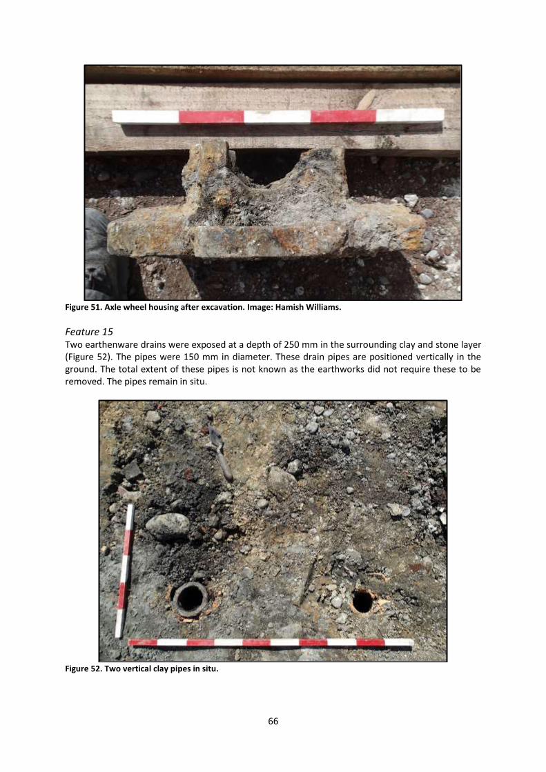
66
Figure 51. Axle wheel housing after excavation. Image: Hamish Williams.
Feature 15 Two earthenware drains were exposed at a depth of 250 mm in the surrounding clay and stone layer (Figure 52). The pipes were 150 mm in diameter. These drain pipes are positioned vertically in the ground. The total extent of these pipes is not known as the earthworks did not require these to be removed. The pipes remain in situ.
Figure 52. Two vertical clay pipes in situ.

67
Feature 16 During excavation for the installation of a new concrete drain, an artefact deposit was exposed in the north wall of the trench at a depth of 1450 mm (Figure 53). This deposit is located in a compacted yellow clay with brown inclusion layer. The deposit consisted of ceramic, glass, bone and shell. Material was collected for further analysis, but some material remains in situ.
Figure 53. Artefact deposit in the north wall of the drainage trench. Facing north.
Feature 17 Scrap timbers were exposed at a depth of 1000 mm in a blue pug layer (Figure 54). The timber was a golden yellow and was located in the blue pug clay layer of the reclamation fill. There were no fasteners associated with the timber, although notches had been cut into the timber and the timbers had circular saw marks. The timbers were removed during excavation work for the drainage works. No sample was retained, due to the lack of context.

68
Figure 54. Feature 17 timbers.
Feature 18 A complete glass bottle was exposed at a depth of 3800 mm in a blue pug clay layer (Figure 55). The bottle was located in the blue pug clay layer in the stage 1 drainage trench. The bottle was recovered for further analysis.
Figure 55. Whole glass bottle in situ.
Feature 19 A bone was recovered from a depth of 4000 mm. This bone was exposed during earthworks for the drainage trench during stage 1 in a blue pug clay layer. The bone was taken back to the artefact lab for further analysis.

69
Feature 20 A glass bottle with a missing rim was exposed during earthworks at a depth of 450 mm in a compacted yellow clay layer. The bottle was excavated and photographed in situ before being removed for further analysis (Figure 56). Once the bottle was removed from the surrounding yellow clay, it left an imprint of a label, which was incomplete (Figure 57). Unfortunately, once removed from the site the label and the clay into which it was set dried and crumbled. The bottle was a large squat black beer bottle, a type usually associated with beer and spirits such as whisky and gin. No embossing was noted on the bottle, with the label imprint in the clay the only indication of contents. The label was only partially represented, making it difficult to make out the details. The partial words TH … / R… / LO… / S… were visible in the centre of the label, with [V]ICTORI[A] running across the base. TRADE [MARK] was visible above the bar near the top of the label. It is most likely that this refers to a brand of stout, probably London stout. The bottling company and/or brewery is not known, although the bottling firm of M. B. Foster and Sons, of the Victoria Export Stores, London, is a possibility, as is Bass’ The Real London Stout (Low 2015, pers. comm.).
Figure 56. Bottle as exposed in situ.

70
Figure 57. Label as seen in situ after the removal of the bottle.
Feature 24 A small deposit of artefacts was exposed at a depth of 600 mm in compacted clay, slightly to the north of the produce sheds (M36/318; Figure 58). The artefacts from this feature were recovered.
Figure 58. Artefact scatter with an animal bone and glass bottle base.

71
Feature 42 Feature 42 was a small (300 mm by 350 mm) deposit of broken ceramic, broken glass and faunal remains. This deposit was exposed at a depth between 450 mm and 500 mm in a compacted clay layer. The material was collected and removed from site for further analysis.
Feature 50 A large rubbish deposit was exposed at a depth of 600 mm in a clay and rubble mix layer (Figure 59). The deposit measured 1500 mm in length by 1400 mm in width. The depth is unknown as the deposit was exposed at the depth required for the project. As such, the deposit was not excavated and remains in situ. The artefacts exposed in the deposit included of broken black beer bottles and white ceramics fragments.
Figure 59. Rubbish deposit exposed at a depth of 600 mm. Facing northwest.
Feature 51 The remains of a timber structure were exposed at a depth of 250 mm in a compacted clay layer, to the west of the produce sheds (Figure 60 and Figure 61). The structure consisted of three pieces of timber, dark red in colour, and measured 1150 mm by 950 mm. A timber plank was fastened with metal nails to two cross beams. A metal bracket was positioned on the top of a piece of planking. There was no evidence to indicate that the structure was anchored to the ground and it seems unlikely that it was in situ. No timber samples were collected due to the unknown origin of this feature. The timber structure was removed form site during further excavation.

72
Figure 60. The timber structure recorded as Feature 51. Facing south.
Figure 61. Drawing of timber structure.
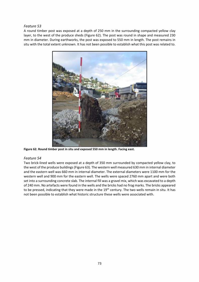
73
Feature 53 A round timber post was exposed at a depth of 250 mm in the surrounding compacted yellow clay layer, to the west of the produce sheds (Figure 62). The post was round in shape and measured 230 mm in diameter. During earthworks, the post was exposed to 550 mm in length. The post remains in situ with the total extent unknown. It has not been possible to establish what this post was related to.
Figure 62. Round timber post in situ and exposed 550 mm in length. Facing east.
Feature 54 Two brick-lined wells were exposed at a depth of 350 mm surrounded by compacted yellow clay, to the west of the produce buildings (Figure 63). The western well measured 630 mm in internal diameter and the eastern well was 660 mm in internal diameter. The external diameters were 1100 mm for the western well and 900 mm for the eastern well. The wells were spaced 2760 mm apart and were both set into a surrounding concrete slab. The internal fill was a gravel mix, which was excavated to a depth of 240 mm. No artefacts were found in the wells and the bricks had no frog marks. The bricks appeared to be pressed, indicating that they were made in the 19th century. The two wells remain in situ. It has not been possible to establish what historic structure these wells were associated with.
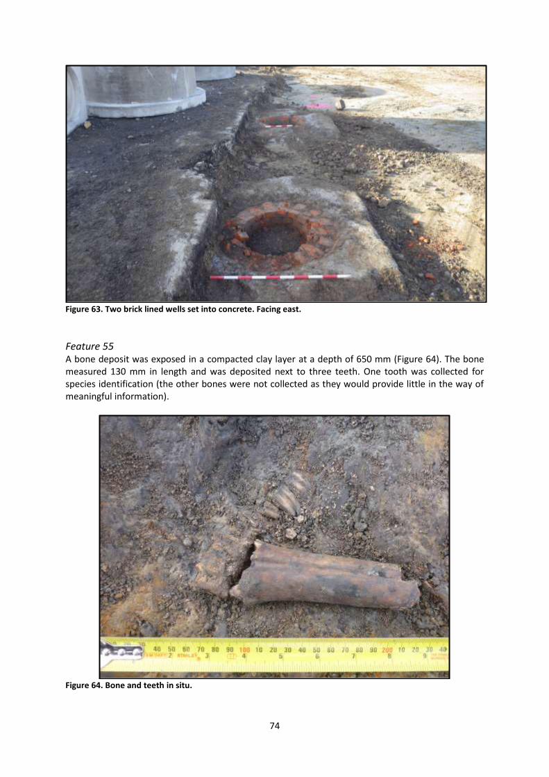
74
Figure 63. Two brick lined wells set into concrete. Facing east.
Feature 55 A bone deposit was exposed in a compacted clay layer at a depth of 650 mm (Figure 64). The bone measured 130 mm in length and was deposited next to three teeth. One tooth was collected for species identification (the other bones were not collected as they would provide little in the way of meaningful information).
Figure 64. Bone and teeth in situ.
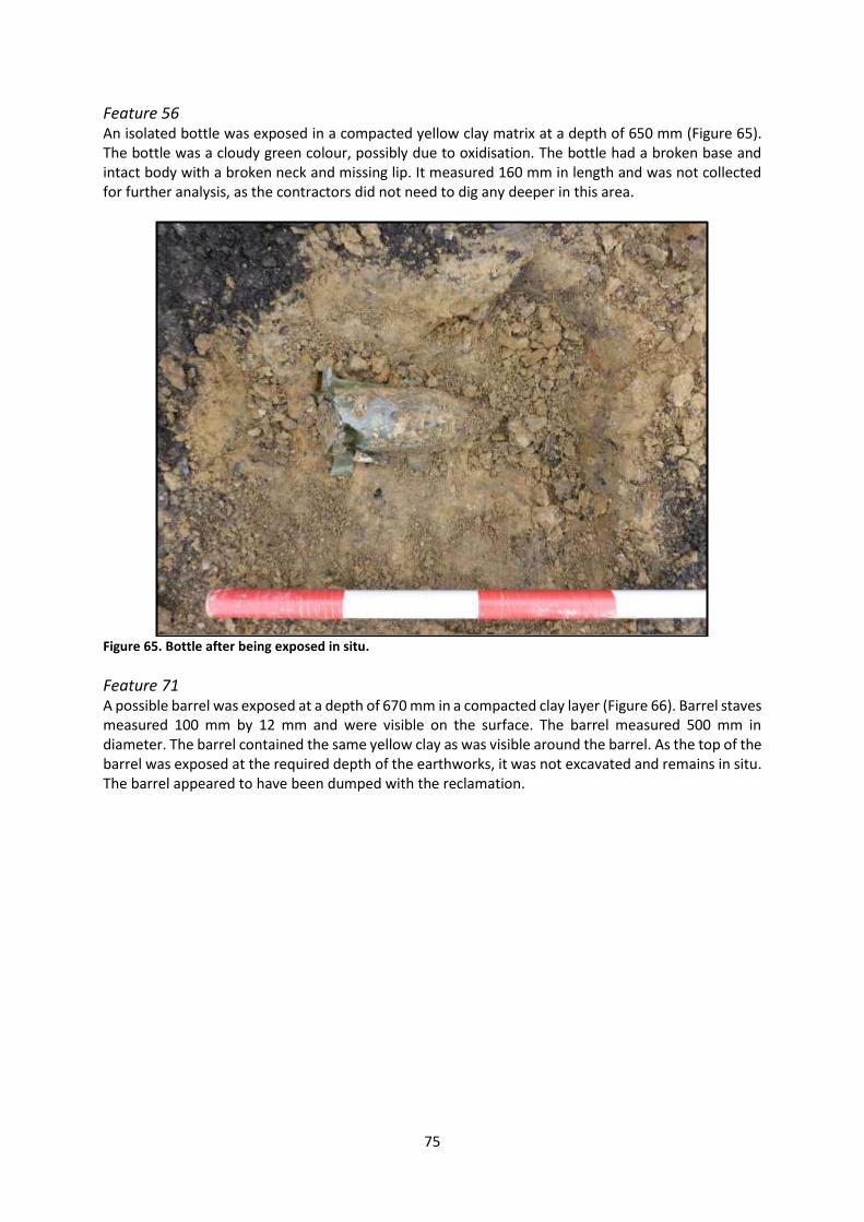
75
Feature 56 An isolated bottle was exposed in a compacted yellow clay matrix at a depth of 650 mm (Figure 65). The bottle was a cloudy green colour, possibly due to oxidisation. The bottle had a broken base and intact body with a broken neck and missing lip. It measured 160 mm in length and was not collected for further analysis, as the contractors did not need to dig any deeper in this area.
Figure 65. Bottle after being exposed in situ.
Feature 71 A possible barrel was exposed at a depth of 670 mm in a compacted clay layer (Figure 66). Barrel staves measured 100 mm by 12 mm and were visible on the surface. The barrel measured 500 mm in diameter. The barrel contained the same yellow clay as was visible around the barrel. As the top of the barrel was exposed at the required depth of the earthworks, it was not excavated and remains in situ. The barrel appeared to have been dumped with the reclamation.

76
Figure 66. Barrel located in fine compacted clay showing evidence of individual staves.
Artefact analysis
Feature 11 Four fragments of an adult male shoe or boot were the only artefacts recovered from Feature 11 (Figure 67). The shoe or boot had a medium square toe (Pannell 1903) and had been manufactured using pegs to attached the sole and upper. A line of peg holes was also visible running through the centre of the sole, likely intended as reinforcing. Vertical attachment, or the use of nails and pegs to attach the heels, soles and uppers of footwear together, was the most common form of shoe manufacture during the latter half of the 19th century. The use of wooden pegs was particularly prevalent during the first half of the 19th century, after the development of hand-operated machines for pegging shoes and boots together. Automated pegging machines were invented in the 1850s, although these were soon made obsolete by other developments in the 1860s and 1870s (Anderson 1968: 59-61). Consequently, pegged shoes and boots are usually dated to the early to mid-19th century, although it is possible that individual shoe-makers may have continued to use the method as late as the 1880s and 1890s.
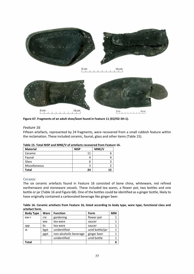
77
Figure 67. Fragments of an adult shoe/boot found in Feature 11 (EQ702-SH-1).
Feature 16 Fifteen artefacts, represented by 24 fragments, were recovered from a small rubbish feature within the reclamation. These included ceramic, faunal, glass and other items (Table 15). Table 15. Total NISP and MNE/V of artefacts recovered from Feature 16.
Material NISP MNE/V
Ceramic 11 6
Faunal 4 4
Glass 6 3
Miscellaneous 3 2
Total 24 15
Ceramic The six ceramic artefacts found in Feature 16 consisted of bone china, whiteware, red refined earthenware and stoneware vessels. These included tea wares, a flower pot, two bottles and one bottle or jar (Table 16 and Figure 68). One of the bottles could be identified as a ginger bottle, likely to have originally contained a carbonated beverage like ginger beer. Table 16. Ceramic artefacts from Feature 16, listed according to body type, ware type, functional class and artefact form.
Body Type Ware Function Form MNI
ew-r rre gardening flower pot 1
ww tea ware saucer 1
spp bc tea ware saucer 1
st bgst unidentified unid bottle/jar 1
pgst non-alcoholic beverage ginger beer 1 unidentified unid bottle 1
Total
6

78
Three of the six ceramics were decorated. Decorative techniques included gilt banding, sponged decoration and relief moulding (Table 17). Hairline gilt banding is a common decorative technique on 19th century ceramics, particularly on bone china tea wares. Sponged decoration is also frequently found on 19th century ceramics. The relief moulding noted on the stoneware bottle took the form of a band of repeating circles around the shoulder of the vessel. No maker’s marks were visible on any of these vessels. Table 17. Decorated ceramics from Feature 16, listed according to decorative technique, pattern name, ware type and artefact form.
Technique Pattern name/motif Ware Form MNI
gilt hl bnd bc saucer 1
relief unid: geometric pgst unid bottle 1
sponged sponged spirals ww saucer 1
Total
3
Figure 68. Selected ceramic vessels from Feature 16. Clockwise from top left: stoneware ginger beer bottle (EQ702-C-16), stoneware bottle with relief moulded decoration (EQ702-C-20), Bristol-glazed stoneware bottle or jar (EQ702-C-18), sponged saucer (EQ702-C-17).
Faunal Four faunal elements were identified in the Feature 16 assemblage. These consisted of one fragment of cockle shell, two cow ribs and one sheep scapula (Table 18). Table 18. Total NISP and MNE of faunal remains from Feature 16, listed according to species common name and element.
Species common name Element NISP MNE
cockle body 1 1
cow rib 2 2
sheep scapula 1 1
Total
4 4

79
These mammal bones represented a total of three individual butchery units, including a cow chuck or rib, a cow chuck, rib, brisket or loin and a sheep forequarter (Table 19). Possible cut marks were noted on the shaft of one of the cow ribs, but no other butchery marks were evident. It was not possible to establish the age of death for the animals represented. Table 19. Total MNBU for faunal assemblage from Feature 16, listed according to species common name and butchery unit.
Species common name Butchery unit MNBU
cow chuck/rib 1
chuck/rib/brisket/loin 1
sheep forequarter 1
Total
3
Glass Three glass artefacts were found in the feature, consisting of a black beer bottle, a wide mouth pickle or salt jar and an oval pharmaceutical bottle (Table 20 and Figure 69). No manufacturer’s marks or product details were visible on these bottles, but manufacturing evidence – including the use of dip moulds, two piece moulds and the presence of air bubbles in the glass – is consistent with a 19th century date of manufacture. The black beer bottle, although primarily associated with beer, may have been used to hold a variety of alcoholic and non-alcoholic beverages during its use life. Similarly, the wide mouth jar and pharmaceutical bottle may have been used for a range of purposes other than their initial intended function before they were discarded. Table 20. Total NISP and MNV of glass artefacts from Feature 16, listed according to functional class and common name.
Class Common name NISP MNV
alcohol black beer 1 1
food/storage wide mouth pickle/salt jar 4 1
pharmaceutical oval pharmaceutical (small) 1 1
Total
6 3
Figure 69. Glass artefacts from Feature 16. Left to right: wide mouth jar (EQ702-G-8), oval pharmaceutical bottle (EQ702-G-7), black beer (EQ702-G-6).
Miscellaneous Lastly, two smoking pipes were also found in Feature 16 (Figure 70). These consisted of two stem fragments, one of which had a glazed bite. No identifying marks were visible on the stems.

80
Figure 70. Clay smoking pipe stem fragments recovered from Feature 16. Left: glazed bite (EQ702-S-1), undiagnostic stem fragments (EQ702-S-2).
Feature 18 Two artefacts were recovered from this feature, consisting of part of a large black porter bottle and a complete ring seal wine/beer bottle (Figure 71). Neither of these were embossed, but manufacturing evidence on the glass is consistent with a 19th century date of manufacture.
Figure 71. Glass artefacts from Feature 18. Left: black porter bottle base (EQ702-G-9). Right: small champagne shape ring seal wine/beer bottle (EQ702-G-10).
Feature 19 A complete, unfused cow femur was the only object recovered from Feature 19. This was identified as the rump/hindshank butchery unit and had been sawn through the distal epiphysis.
Feature 24 Feature 24 contained two artefacts, identified as a sheep metatarsal and the base of a large squat black beer bottle, measuring 94 mm in diameter (Table 21 and Figure 72). No butchery marks were
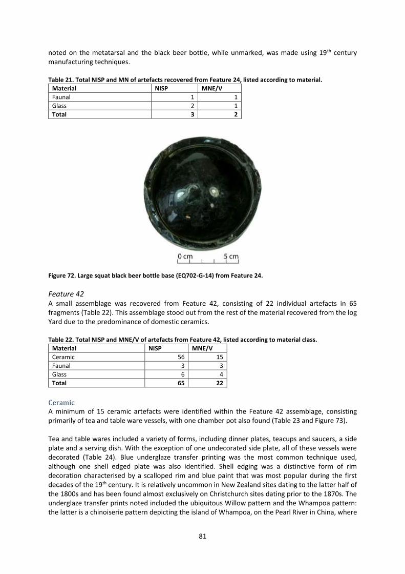
81
noted on the metatarsal and the black beer bottle, while unmarked, was made using 19th century manufacturing techniques. Table 21. Total NISP and MN of artefacts recovered from Feature 24, listed according to material.
Material NISP MNE/V
Faunal 1 1
Glass 2 1
Total 3 2
Figure 72. Large squat black beer bottle base (EQ702-G-14) from Feature 24.
Feature 42 A small assemblage was recovered from Feature 42, consisting of 22 individual artefacts in 65 fragments (Table 22). This assemblage stood out from the rest of the material recovered from the log Yard due to the predominance of domestic ceramics. Table 22. Total NISP and MNE/V of artefacts from Feature 42, listed according to material class.
Material NISP MNE/V
Ceramic 56 15
Faunal 3 3
Glass 6 4
Total 65 22
Ceramic A minimum of 15 ceramic artefacts were identified within the Feature 42 assemblage, consisting primarily of tea and table ware vessels, with one chamber pot also found (Table 23 and Figure 73). Tea and table wares included a variety of forms, including dinner plates, teacups and saucers, a side plate and a serving dish. With the exception of one undecorated side plate, all of these vessels were decorated (Table 24). Blue underglaze transfer printing was the most common technique used, although one shell edged plate was also identified. Shell edging was a distinctive form of rim decoration characterised by a scalloped rim and blue paint that was most popular during the first decades of the 19th century. It is relatively uncommon in New Zealand sites dating to the latter half of the 1800s and has been found almost exclusively on Christchurch sites dating prior to the 1870s. The underglaze transfer prints noted included the ubiquitous Willow pattern and the Whampoa pattern: the latter is a chinoiserie pattern depicting the island of Whampoa, on the Pearl River in China, where

82
European trading vessels were required to anchor from the 17th century onwards (Transferware Collector’s Club 2016). The same pattern has been found in an 1860s assemblage elsewhere in Christchurch (Garland et al. 2015). Table 23. Ceramic artefacts from Feature 42, listed according to body type, ware type, functional class and artefact form.
Body Type Ware Function Form MNI
ew-r ww household chamber pot 1
table ware dinner plate 3
plate 1
serving dish 2
tea ware saucer 1
teacup 4
tea/table ware cup/bowl/jug 1
dish 1
spp bc table ware side plate 1
Total
15
Unidentified patterns consisted of motifs featuring floral, foliage and geometric elements in addition to at least three scenic and/or ‘romantic’ patterns. Romantic patterns, which often feature a body of water bordered by a cottage or castle and trees with figures in the foreground, became popular during the early-mid 19th century, partly in response to the classical revival of the early 19th century (Samford 1997: 13-14). Although they were produced from the late 18th century until the late 19th century, their peak period of production appears to have been during the period from the 1830s until the 1850s (Samford 1997: 6). Similarly, patterns with central motifs – such as the vessels represented in this assemblage – were most commonly produced during the early-mid 19th century. Interestingly, given the archaeological context of this site, the decoration on two of the teacups featured sailing boats as the central motif. The chamber pot was also decorated, with a transfer print of the marble pattern on the exterior surface. No legible maker’s marks were present on this, or any of the other vessels from the assemblage. Table 24. Decorated ceramics from Feature 42, listed according to decorative technique, pattern name, ware type and artefact form.
Technique Pattern name/motif Ware Form MNI
shell edged shell edged ww dinner plate 1
ugtp marble ww chamber pot 1
unid: aesthetic floral/foliage/vignette ww teacup 1
unid: basket weave/foliage ww teacup 0*
unid: romantic scenery ww dish 1
unid: scenic/architecture/landscape ww plate 1
unid: scenic/boat/geometric ww teacup 2
unid: strawberry ww teacup 1
unid: urn/foliage ww saucer 1
Whampoa ww cup/bowl/jug 1
dinner plate 1
Willow ww dinner plate 1
serving dish 2
Total
14 *MNV of 0, as fragment may have belonged with one of the other vessels identified in the assemblage.

83
Figure 73. Selected ceramic artefacts from Feature 42. A (left to right): Willow pattern serving dish (EQ702-C-5), Willow pattern dinner plate (EQ702-C-6), scenic patterned dish (EQ702-C-8). B: sailing boat decorated teacup (EQ702-C-1), sailing boat decorated teacup (EQ702-C-1), strawberry patterned teacup (EQ702-C-7), transfer printed saucer (EQ702-C-15). C: shell-edged plate (702-C-3), scenic patterned plate (EQ702-C-9), basket weave patterned teacup (EQ702-C-14), brown aesthetic patterned teacup (EQ702-C-10). D: Whampoa patterned dinner plate (EQ702-C-2), marble patterned chamber pot (EQ702-C-12).
Faunal Three faunal elements were identified in the Feature 42 assemblage, consisting of two sheep femurs and one sheep tibia (Table 25).
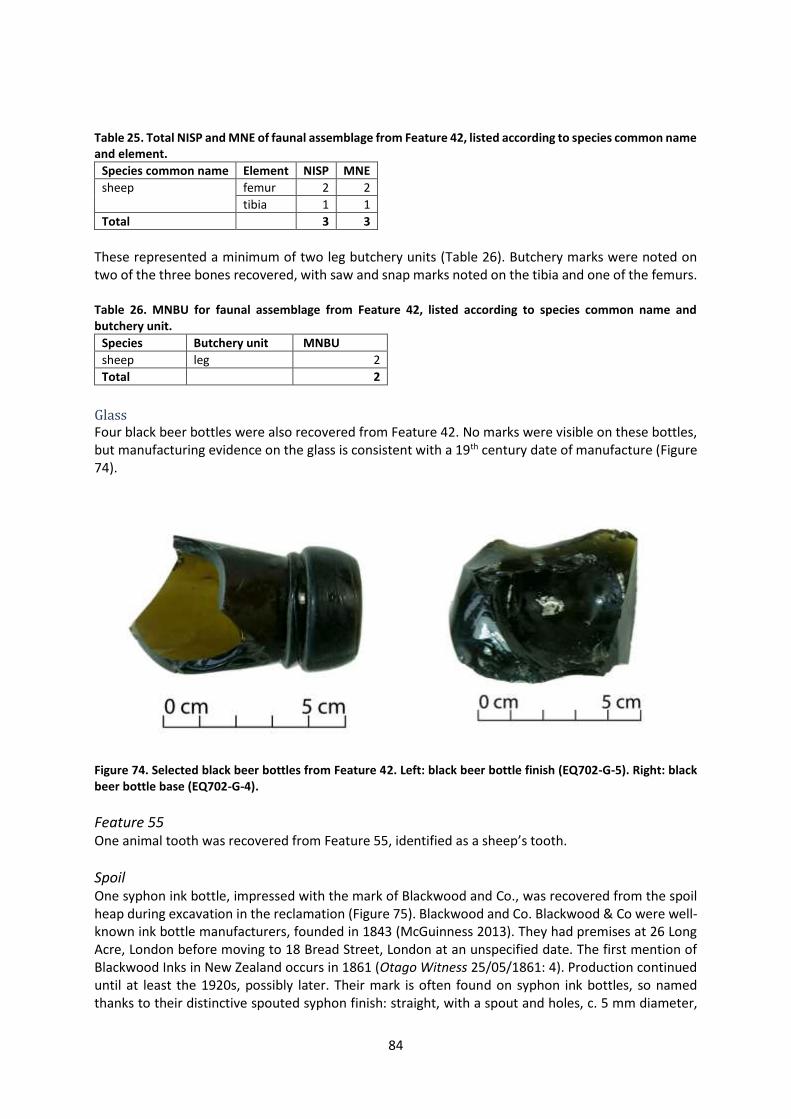
84
Table 25. Total NISP and MNE of faunal assemblage from Feature 42, listed according to species common name and element.
Species common name Element NISP MNE
sheep femur 2 2
tibia 1 1
Total
3 3
These represented a minimum of two leg butchery units (Table 26). Butchery marks were noted on two of the three bones recovered, with saw and snap marks noted on the tibia and one of the femurs. Table 26. MNBU for faunal assemblage from Feature 42, listed according to species common name and butchery unit.
Species Butchery unit MNBU
sheep leg 2
Total
2
Glass Four black beer bottles were also recovered from Feature 42. No marks were visible on these bottles, but manufacturing evidence on the glass is consistent with a 19th century date of manufacture (Figure 74).
Figure 74. Selected black beer bottles from Feature 42. Left: black beer bottle finish (EQ702-G-5). Right: black beer bottle base (EQ702-G-4).
Feature 55 One animal tooth was recovered from Feature 55, identified as a sheep’s tooth.
Spoil One syphon ink bottle, impressed with the mark of Blackwood and Co., was recovered from the spoil heap during excavation in the reclamation (Figure 75). Blackwood and Co. Blackwood & Co were well-known ink bottle manufacturers, founded in 1843 (McGuinness 2013). They had premises at 26 Long Acre, London before moving to 18 Bread Street, London at an unspecified date. The first mention of Blackwood Inks in New Zealand occurs in 1861 (Otago Witness 25/05/1861: 4). Production continued until at least the 1920s, possibly later. Their mark is often found on syphon ink bottles, so named thanks to their distinctive spouted syphon finish: straight, with a spout and holes, c. 5 mm diameter,
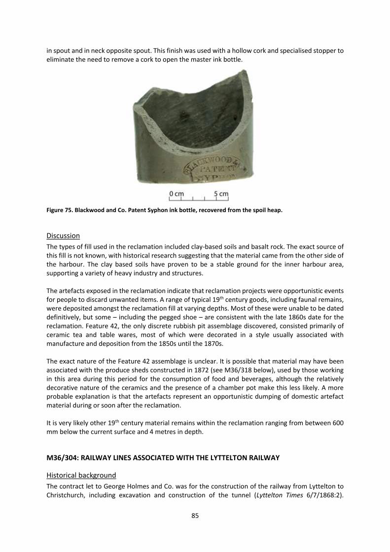
85
in spout and in neck opposite spout. This finish was used with a hollow cork and specialised stopper to eliminate the need to remove a cork to open the master ink bottle.
Figure 75. Blackwood and Co. Patent Syphon ink bottle, recovered from the spoil heap.
Discussion
The types of fill used in the reclamation included clay-based soils and basalt rock. The exact source of this fill is not known, with historical research suggesting that the material came from the other side of the harbour. The clay based soils have proven to be a stable ground for the inner harbour area, supporting a variety of heavy industry and structures. The artefacts exposed in the reclamation indicate that reclamation projects were opportunistic events for people to discard unwanted items. A range of typical 19th century goods, including faunal remains, were deposited amongst the reclamation fill at varying depths. Most of these were unable to be dated definitively, but some – including the pegged shoe – are consistent with the late 1860s date for the reclamation. Feature 42, the only discrete rubbish pit assemblage discovered, consisted primarily of ceramic tea and table wares, most of which were decorated in a style usually associated with manufacture and deposition from the 1850s until the 1870s. The exact nature of the Feature 42 assemblage is unclear. It is possible that material may have been associated with the produce sheds constructed in 1872 (see M36/318 below), used by those working in this area during this period for the consumption of food and beverages, although the relatively decorative nature of the ceramics and the presence of a chamber pot make this less likely. A more probable explanation is that the artefacts represent an opportunistic dumping of domestic artefact material during or soon after the reclamation. It is very likely other 19th century material remains within the reclamation ranging from between 600 mm below the current surface and 4 metres in depth.
M36/304: RAILWAY LINES ASSOCIATED WITH THE LYTTELTON RAILWAY
Historical background
The contract let to George Holmes and Co. was for the construction of the railway from Lyttelton to Christchurch, including excavation and construction of the tunnel (Lyttelton Times 6/7/1868:2).

86
Holmes and Co.’s contract included construction of a single line of ballasted permanent way (railway line), but station buildings were excluded (Pierre 1964:69). Temporary rails were laid through the tunnel by November 1867, when the first locomotive went through, and passenger services commenced in December 1867 (Pierre 1964:70). However, works progressed on the Lyttelton side of the tunnel as the tunnel was under construction. In July 1867 it was reported that the rail reclamation would not bear the weight of a locomotive, but by August 1867 work had commenced on the construction of the permanent way at the port (Press 1/7/1867:2 & 7/8/1867:2). By October 1867 the permanent way was ballasted and laid up to the government wharf (Press 26/10/1867:2). The rail track at Lyttelton consisted of double-headed wrought-iron rails weighing 70 pound per yard (Pierre 1964:103-105). They were keyed into chairs fastened onto hardwood sleepers. The original sleepers at the Lyttelton end of the line were 9 feet long (2.74 m), 10 inches wide (254 mm) and 5 inches thick (127 mm). However, it is estimated that sleepers had a life of only four-and-a-half to six years (Pierre 1964:104). The rails were manufactured in London and timber for sleepers was felled at Pigeon Bay, but a range of timbers were used, including jarrah, ironbark, mataī, tōtara, kōwhai, mānuka and black beech (Lyttelton Times 11/7/1863:5, Pierre 1964:104). Ballast was laid to a depth of 12 inches under the sleepers and the contract specified “good clean gravel or broken stones” of not larger than 3 inches in diameter (Pierre 1964:104). Under the Canterbury Provincial Government the lines of the Canterbury rail system were laid in a gauge of 5 feet 3 inches (1.6 m; Scotter 1968:133). The Railways Act of 1870 implemented a standard gauge of 3 feet 6 inches (1.07 m) for New Zealand’s rail network (Pierre 1964:86). In 1872 to 1876 a separate narrow gauge line was laid parallel to the Christchurch to Lyttelton railway and was laid inside the broad gauge line through the Lyttelton railway tunnel (Pierre 1964:87-89, Scotter 1968:133). The new narrow gauge line at the port was extended to Gladstone Pier and in 1877 was laid on the breastwork wharf, screw-pile jetty and No. 3, and connected to the Tunnel Jetty and Peacock’s Wharf in 1878 (Scotter 1968:133).
Results of archaeological monitoring
Seven features were found that are likely to have been associated with the railway lines, most of which were timber sleepers (Figure 76).

87
Figure 76. The railway lines (in 1954) overlaid on the archaeological features found. Base map supplied by LPC (LPC plan reference: 1-1171).
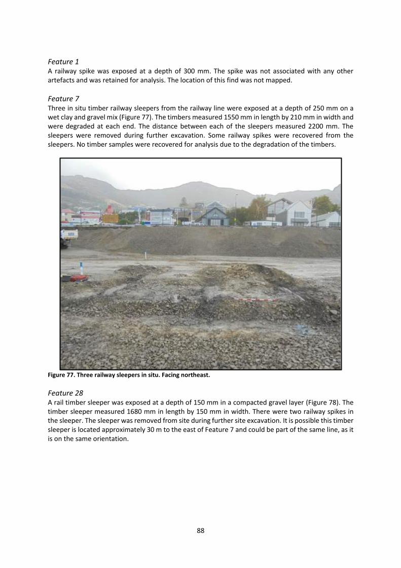
88
Feature 1 A railway spike was exposed at a depth of 300 mm. The spike was not associated with any other artefacts and was retained for analysis. The location of this find was not mapped.
Feature 7 Three in situ timber railway sleepers from the railway line were exposed at a depth of 250 mm on a wet clay and gravel mix (Figure 77). The timbers measured 1550 mm in length by 210 mm in width and were degraded at each end. The distance between each of the sleepers measured 2200 mm. The sleepers were removed during further excavation. Some railway spikes were recovered from the sleepers. No timber samples were recovered for analysis due to the degradation of the timbers.
Figure 77. Three railway sleepers in situ. Facing northeast.
Feature 28 A rail timber sleeper was exposed at a depth of 150 mm in a compacted gravel layer (Figure 78). The timber sleeper measured 1680 mm in length by 150 mm in width. There were two railway spikes in the sleeper. The sleeper was removed from site during further site excavation. It is possible this timber sleeper is located approximately 30 m to the east of Feature 7 and could be part of the same line, as it is on the same orientation.

89
Figure 78. Feature 28 in situ with two rail spikes in situ (left of the photo).
Feature 29 A rail iron (in a secondary context) was exposed at a depth of 150 mm (Figure 79). The rail track was located in fine loose red scoria layer. The total length of the rail is unknown as it was buried into the ground and the rail was not removed as part of the project.
Figure 79. Rail line exposed in fine loose red scoria.
Feature 32 Two timber sleepers were exposed at a depth of 250 mm in a clay and gravel mix (Figure 80). This feature was located 1400 mm west of Feature 28 and the two are likely to be associated. The distance between each sleeper measured 750 mm. The two timbers were very degraded to the point where dark soil stains indicated where organic material had once existed. Three rail spikes were present and were not recovered. The timbers and soil stain was removed during further excavation. The location of this find was not mapped.

90
Figure 80. Two sleepers in situ. Facing northeast.
Feature 38 Two timber rail sleepers were exposed at a depth of 200 mm during excavation works. The sleepers were removed without the archaeologist on site. It is likely these sleepers were located in the surrounding compacted clay layer. An approximate location was recorded for both of the sleepers as indicated by the contract workers. Based on these locations, Feature 38 was not on the same line as the other timber sleepers. It is possible these two timber sleeper represent a different rail line.
Artefact analysis
Feature 1 Feature 1 consisted of a single ferrous railway spike, measuring 130 mm in length and 16 mm in shank width (Figure 81). The spike had a brad head, tapered to a chisel point and appears to have been hand wrought. Hand wrought nails were most prevalent in New Zealand in the early-mid-19th century, although spikes and larger fasteners continued to be handmade for much longer than their smaller counterparts (Middleton 2005).

91
Figure 81. Spike from Feature 1 (EQ702-M-31).
Feature 7 The Feature 7 assemblage consisted of three spikes with brad heads and chisel points, measuring approximately 128 mm in length and 17 mm in maximum shaft width (Figure 82). Brad heads are commonly found on flooring nails and railway spikes: the latter were used to fix heavy timbers (Cottrell 2006, Middleton 2005).
Figure 82. Brad head spikes with chisel points from Feature 7 (EQ702-M-6).
Railway spike sample Four other railway spikes were sampled from across site and recovered for identification (Figure 83). These were all of what appeared to be wrought manufacture, with thick flattened brad heads and blunt points, measuring approximately 21 mm in maximum shaft thickness and approximately 131 mm in length.

92
Figure 83. Four railway spikes collected from across the site (EQ702-M-46).
Discussion
The rail sleepers exposed during earthworks represents the rail activity that occurred in the inner harbour. Based on the lengths of the sleepers, it is likely they were installed following the 1870 act and represent the 3 feet 6 inch gauge rail. The timber sleepers also illustrate where rail lines were laid on the reclamation, which indicate points of transport servicing adjacent warehouses, storehouses and industry. Features 7, 32 and 38 appear to be associated with lines that were present in 1954, although it has not been possible to establish when these were laid. Feature 29, however, is underneath a building that was extant in 1954 and must therefore predate this. All the artefacts recovered from M36/304 were identified as railway spikes and would have been used in the construction of the railway.
M36/310: CUNNINGHAM’S STORE
Historical research has shown that the archaeological site and building identified as the New Zealand Loan and Mercantile Company grain store was built in 1878-79 for P. Cunningham and Co., and had no association with the Loan and Mercantile company5 (Star 25/9/1879:3, Press 25/9/1879:3; Figure 84).
Historical background
The grain store was built of brick and stone on “unusually heavy” concrete foundations to a depth of 12 feet and width of 3 feet (Press 25/9/1879:3). A 14 foot high stone retaining wall was erected on these foundations, to the level of Norwich Quay. The bricks were made from locally sourced clay by Royse, Stead and Co. (Press 25/9/1879:3). The building had two storeys with brick walls and a concrete floor on the lower storey (Star 25/9/1879:3). It was 267 feet long and 60 feet wide with a height of 16
5 The original site record form for this site identified the building as the Loan and Mercantile store (Carter 2014a).

93
feet on the lower storey. An unusual feature of the grain store was an elevator that allowed grain to be offloaded from the adjacent railway siding and carried to the upper floor. The elevator was powered by a gas engine specially imported by Cunningham from England (Nelson Evening Mail 29/7/1881:1). The building was demolished in 1980 (Beaumont et al. 2014: 381).
Figure 84. Norwich Quay, view east, c.1880, Burton Brothers photograph (Te Papa Tongarewa Museum of New Zealand: ref. C.011661). P. Cunningham and Co. grain store situated on the right hand side of Norwich Quay.
Results of archaeological monitoring
Several structural features relating to Cunningham’s store were exposed during the earthworks (Figure 85).
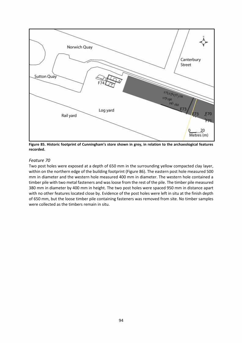
94
Figure 85. Historic footprint of Cunningham’s store shown in grey, in relation to the archaeological features recorded.
Feature 70 Two post holes were exposed at a depth of 650 mm in the surrounding yellow compacted clay layer, within on the northern edge of the building footprint (Figure 86). The eastern post hole measured 500 mm in diameter and the western hole measured 400 mm in diameter. The western hole contained a timber pile with two metal fasteners and was loose from the rest of the pile. The timber pile measured 380 mm in diameter by 400 mm in height. The two post holes were spaced 950 mm in distance apart with no other features located close by. Evidence of the post holes were left in situ at the finish depth of 650 mm, but the loose timber pile containing fasteners was removed from site. No timber samples were collected as the timbers remain in situ.
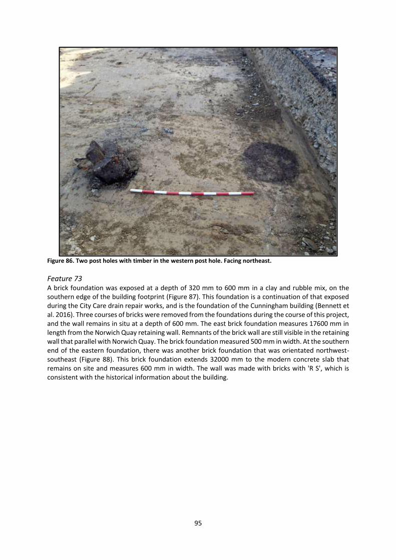
95
Figure 86. Two post holes with timber in the western post hole. Facing northeast.
Feature 73 A brick foundation was exposed at a depth of 320 mm to 600 mm in a clay and rubble mix, on the southern edge of the building footprint (Figure 87). This foundation is a continuation of that exposed during the City Care drain repair works, and is the foundation of the Cunningham building (Bennett et al. 2016). Three courses of bricks were removed from the foundations during the course of this project, and the wall remains in situ at a depth of 600 mm. The east brick foundation measures 17600 mm in length from the Norwich Quay retaining wall. Remnants of the brick wall are still visible in the retaining wall that parallel with Norwich Quay. The brick foundation measured 500 mm in width. At the southern end of the eastern foundation, there was another brick foundation that was orientated northwest-southeast (Figure 88). This brick foundation extends 32000 mm to the modern concrete slab that remains on site and measures 600 mm in width. The wall was made with bricks with 'R S', which is consistent with the historical information about the building.

96
Figure 87. Eastern and southern brick foundations. Facing southeast.
Figure 88. Southern brick foundation extending to the modern concrete slab. Facing northwest.

97
Feature 75 At a depth of 600 mm, a timber post was exposed during excavation works (Figure 89). This post is located in gravel and clay mix layer. The square post measured 300 mm by 300 mm and angled to a round post 300 mm in diameter. There was no evidence of fasteners associated with the post. The post remains in situ.
Figure 89. Feature 75 exposed during earthworks. Facing northwest. Image: Luke Tremlett.
Feature 76 At a depth of 600 mm, a timber post was exposed during excavation works (Figure 90). This post is located in a clay and rubble mix. The square post measured 300 mm by 300 mm. There was no evidence of fasteners associated with the post. The post remains in situ.

98
Figure 90. Feature 76 after being exposed. Facing east. Image: Luke Tremlett.
Feature 77 Earthworks exposed a timber post at 600 mm of depth in a clay and stone mixed layer (Figure 91). The post was only partly exposed at this depth and only the top was observed. The post measured 300 mm by 300 mm. The post remains in situ.
Figure 91. Showing the top of Feature 77. Image: Luke Tremlett.

99
Feature 78 A timber post was exposed at 600 mm depth in a stone and clay mixed layer (Figure 92). The post was only partly exposed at this depth and only the top was observed. The post measured 300 mm by 300 mm. The post remains in situ.
Figure 92. Top of Feature 78. Facing west. Image: Luke Tremlett.
Feature 79 A timber post was exposed during excavation works at a depth of 600 mm in a compacted yellow clay layer (Figure 93). The square post measured 300 mm by 300 mm and angled to a round post 300 mm in diameter. The post remains in situ.
Figure 93. Feature 79 as seen during earthworks. Facing south. Image: Luke Tremlett.

100
Feature 80 At a depth of 600 mm, a timber post was exposed during excavation works (Figure 94). This post was exposed at depth in the surrounding compacted clay layer. The square post measured 300 mm by 300 mm. There was no evidence of fasteners associated with the post. The post remains in situ.
Figure 94. Feature 80 as seen during earthworks. Facing south. Image: Luke Tremlett.
Feature 81 A timber post was exposed at 600 mm depth in a compacted clay layer (Figure 95). The post was only partly exposed at this depth and only the top was observed. The post measured 300 mm by 300 mm. The post was not investigated any further during the course of the project and remains in situ.
Figure 95. Feature 81 exposed during earthworks. Facing north. Image: Luke Tremlett.

101
Feature 82 Excavations exposed a timber post at 600 mm depth in a mixed clay and stone mixed layer (Figure 96). The post was only partly exposed on the surface, with only the top visible. The post measured 300 mm by 300 mm. The post was not investigated any further during the course of the project and remains in situ.
Figure 96. Feature 82 exposed during earthworks. Facing west. Image: Luke Tremlett.
Discussion
Cunningham’s store occupied the northwest of the inner harbour log yard. Evidence relating to this structures included substantial brick and concrete foundations and timber posts. The brick and concrete foundations reflect the historical record and provide material evidence of the construction techniques used for the store. The timber posts (Features 75, 76, 77, 78, 79, 80, 81 and 82) are likely to be associated with each other. Each post displays a similar square cut. These are likely to have been used as supporting posts within the building. The archaeological evidence of these features confirms the historical information while also providing a first-hand glimpse into the construction materials and methods.
M36/311: FIRST EASTERN RECLAMATION
Historical background
In 1867 the reclaimed land at the eastern side of the harbour was described as “really an artificial beach” and is seen as such in a photograph taken in 1867 (Press 28/11/1867:2, Figure 30). In the early 1870s the Provincial Government sought to extend the railway to the Officers Point Breakwater and resolved to construct a timber viaduct from the Government jetty to the breakwater (Star 14 March 1871:2, Press 3/5/1871:4, Scotter 1968:82). The contract for construction of the viaduct was let,
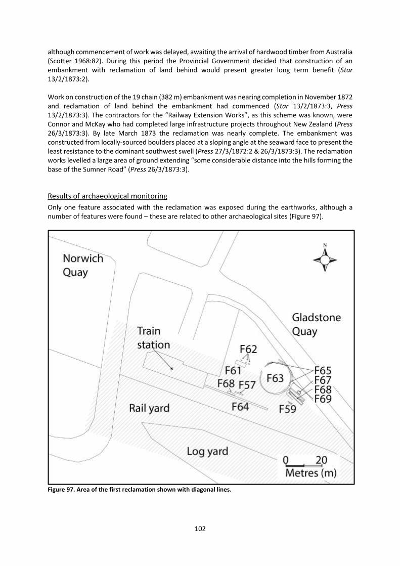
102
although commencement of work was delayed, awaiting the arrival of hardwood timber from Australia (Scotter 1968:82). During this period the Provincial Government decided that construction of an embankment with reclamation of land behind would present greater long term benefit (Star 13/2/1873:2). Work on construction of the 19 chain (382 m) embankment was nearing completion in November 1872 and reclamation of land behind the embankment had commenced (Star 13/2/1873:3, Press 13/2/1873:3). The contractors for the “Railway Extension Works”, as this scheme was known, were Connor and McKay who had completed large infrastructure projects throughout New Zealand (Press 26/3/1873:3). By late March 1873 the reclamation was nearly complete. The embankment was constructed from locally-sourced boulders placed at a sloping angle at the seaward face to present the least resistance to the dominant southwest swell (Press 27/3/1872:2 & 26/3/1873:3). The reclamation works levelled a large area of ground extending “some considerable distance into the hills forming the base of the Sumner Road” (Press 26/3/1873:3).
Results of archaeological monitoring
Only one feature associated with the reclamation was exposed during the earthworks, although a number of features were found – these are related to other archaeological sites (Figure 97).
Figure 97. Area of the first reclamation shown with diagonal lines.
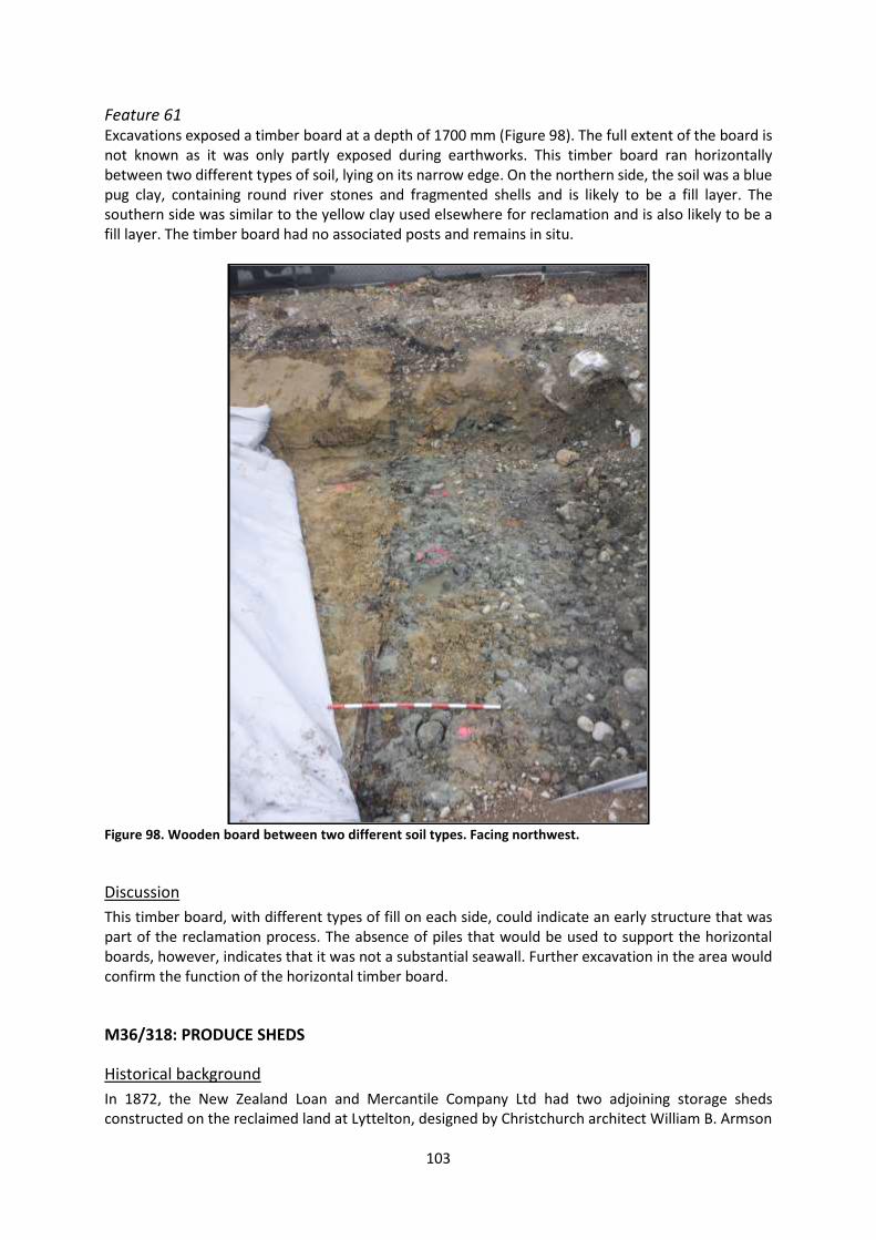
103
Feature 61 Excavations exposed a timber board at a depth of 1700 mm (Figure 98). The full extent of the board is not known as it was only partly exposed during earthworks. This timber board ran horizontally between two different types of soil, lying on its narrow edge. On the northern side, the soil was a blue pug clay, containing round river stones and fragmented shells and is likely to be a fill layer. The southern side was similar to the yellow clay used elsewhere for reclamation and is also likely to be a fill layer. The timber board had no associated posts and remains in situ.
Figure 98. Wooden board between two different soil types. Facing northwest.
Discussion
This timber board, with different types of fill on each side, could indicate an early structure that was part of the reclamation process. The absence of piles that would be used to support the horizontal boards, however, indicates that it was not a substantial seawall. Further excavation in the area would confirm the function of the horizontal timber board.
M36/318: PRODUCE SHEDS
Historical background
In 1872, the New Zealand Loan and Mercantile Company Ltd had two adjoining storage sheds constructed on the reclaimed land at Lyttelton, designed by Christchurch architect William B. Armson

104
(Star 25/10/1871:1; Figure 99). The total dimensions of the building was 293 feet by 60 feet (89.31 x 18.29 metres), containing a grain store of 196 by 60 feet (59.74 x 18.29 metres) and a wool store of 97 by 60 feet (29.57 x 18.29 metres) occupied by Lyttelton firm, Cameron Bros. (Star 28/3/1872:2, Press 27/3/1872:2, 28/3/1872:2). The entire building was initially intended as a grain store so was accordingly designed with strong foundations and floor. Three feet square (0.91 square metre) concrete foundations were built to a depth of one foot (0.30 metre), supporting stone piles placed under each of the main uprights. The walls were of rubble construction, clad in iron, resting directly on the ground on the town side, but supported by a concrete foundation on the seaward side (Star 28/3/1872:2). The floor was laid with four inch thick concrete (Star 28/3/1872:2). New Zealand Loan and Mercantile Company Ltd.’s grain store occupied the eastern end and featured an unusual elliptical roof in galvanised iron (Press 27/3/1872:2). Cameron Bros’ wool store, at the eastern end, housed specialist wool-dumping machinery imported from Sydney. This was driven by a steam engine with a boiler laid on a stone bed with concrete foundations housed in an additional engine-room of 22 by 25 feet (6.70 x 7.62 metres). The boiler required four pumps which were installed on “massive foundations” with a 14 foot (4.27 metre) brick well beneath each pump (Star 28/3/1872:2).
Figure 99. Detail from “Lyttelton”, c.1880s, unknown photographer, James Joseph Gibbs collection. Image: Alexander Turnbull Library: ref. PAColl-0738-1.
Results of archaeological monitoring
A number of archaeological features were recovered within the footprint of the produce sheds, all of which were structural or drainage related (Figure 100). Some of the features described here were outside the footprint of the produce sheds, but are described here as the produce sheds were the closest buildings.
Cameron Bros. wool store (1872)
NZ Loan and Mercantile grain store (1872)
Railway turntable and engine shed (1879)

105
Figure 100. Historic footprint of produce sheds shown in grey.

106
Feature 4 Earthworks exposed a possible brick footing at a depth of 350 mm in a compacted clay and rubble mixed layer, within the footprint of the west produce shed (Figure 101). The brick footing measured 350 mm in length by 370 mm in width by 150 mm in depth. The footing was one course high (150 mm) and the bricks did not have maker’s marks. The bricks were bright orange in colour and appeared to be press moulded. A ceramic fragment was recovered from next to the footing for analysis. The footing is likely to have been associated with the produce shed and was removed as a result of earthworks.
Figure 101. Feature 4 exposed in situ. Ceramic fragments to the north (left) of the brick.
Feature 5 Earthworks for the installation of new stormwater drainage exposed a brick sump at a depth of 200 mm in a compacted stone and clay layer, within the footprint of the west produce shed (Figure 102). The brick sump measured 1250 mm in length by 850 mm in width by 970 mm depth. The sump was constructed out of bricks and a fine cement mortar and the top was cemented, indicating it was no longer in service. The bricks had no maker’s marks. During the investigation of the sump, artefacts were recovered from on top of the sump and the earthenware pipe inlet. Earthenware pipe inlets were connected to the eastern and southern sides of the sump. There was no evidence of what these pipes connected to. The structure was removed to allow the installation of the new concrete stormwater drain (although it was subsequently decided that the new stormwater drain location would be located approximately 4 metres south of the sump’s location). The removal of the brick sump exposed an earthenware pipe that connected to the cast iron drain that runs north-south through the port reclamation and discharges into the inner harbour (recorded as archaeological site M36/344). Given the sump’s location, this is likely to have been installed for the produce sheds.
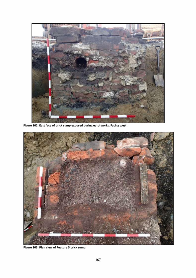
107
Figure 102. East face of brick sump exposed during earthworks. Facing west.
Figure 103. Plan view of Feature 5 brick sump.

108
Feature 44 Part of a timber floor was exposed at a depth of 450-500 mm in the surrounding gravel and tar layer, on the southern edge of the east building footprint (Figure 104 and Figure 105). The timber flooring consisted of two timber planks lying horizontally with metal fasteners in them, with timbers along the north and east sides. The timbers on the sides were placed on their narrow edge and appeared to form an edge to the horizontal boards. There was no evidence of floor joists and the planks were sitting on the soil. The total area of this feature measured 1450 mm by 850 mm. This feature was removed from site. This timber was not sampled for analysis.
Figure 104. Timber flooring in situ (foreground). Facing south.

109
Figure 105. Drawing of timber flooring.
Feature 45 Four timber posts were exposed at a depth of 500 mm in a compacted clay layer, inside the east building footprint (Figure 106). The posts were arranged in a L-shape and orientated east-west. The posts appeared to be driven into the surrounding fine yellow clay. The posts were 250 mm by 300 mm and remain in situ.
Figure 106. Posts, facing northeast.

110
Feature 46 A brick foundation was exposed at a depth of 500 mm in a clay and rubble mixed layer, inside the east building footprint (Figure 107). The foundation was constructed of bricks, concrete and fine mortar. The bricks were bright orange clay and did not have any frog marks. The bricks appeared to be press moulded, although they were very weathered, which hindered identification. The foundation measured 3650 mm in length by 550 mm in width and was two courses high. The depth of feature is unknown as it was removed when the archaeologist was not present.
Figure 107. Brick and concrete foundation in situ. Facing northeast.
Feature 48 A brick sump was exposed at a depth of 550 mm in a clay and rubble mixed layer, to the south of the building footprint (Figure 108). The structure measured 800 mm by 750 mm. The wall of the sump was one brick thick (160 mm) and it was filled with a compacted gravel. The bricks were moulded, and no maker’s marks were visible. The sump was connected to an earthenware pipe. This extended to the northwest for approximately 3600 mm. The total depth of the feature is unknown as it was not fully exposed and remains in situ.

111
Figure 108. Sump shown in situ (Foreground) with clay drain to the northwest. Facing west.
Feature 49 Five stone blocks were exposed in a mixed clay and stone matrix at a depth of 600 mm, immediately to the west of the west building footprint (Figure 109). Given that history records that stone foundations were used to support the main uprights in the building, it seems likely that the blocks were associated with the produce sheds. These blocks measured 550 mm in length by 550 mm in width by 600 mm in depth. The stone was light yellow in colour and was a sedimentary type of rock with fine sand particles. In the centre of each block was a small post hole measuring 150 mm by 220 mm and possibly used to support posts for a building. There was no timber associated with these concrete blocks. The blocks were removed from site.
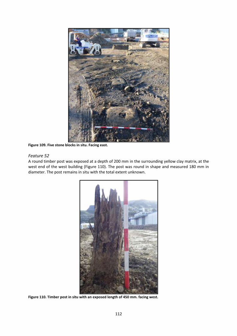
112
Figure 109. Five stone blocks in situ. Facing east.
Feature 52 A round timber post was exposed at a depth of 200 mm in the surrounding yellow clay matrix, at the west end of the west building (Figure 110). The post was round in shape and measured 180 mm in diameter. The post remains in situ with the total extent unknown.
Figure 110. Timber post in situ with an exposed length of 450 mm. facing west.
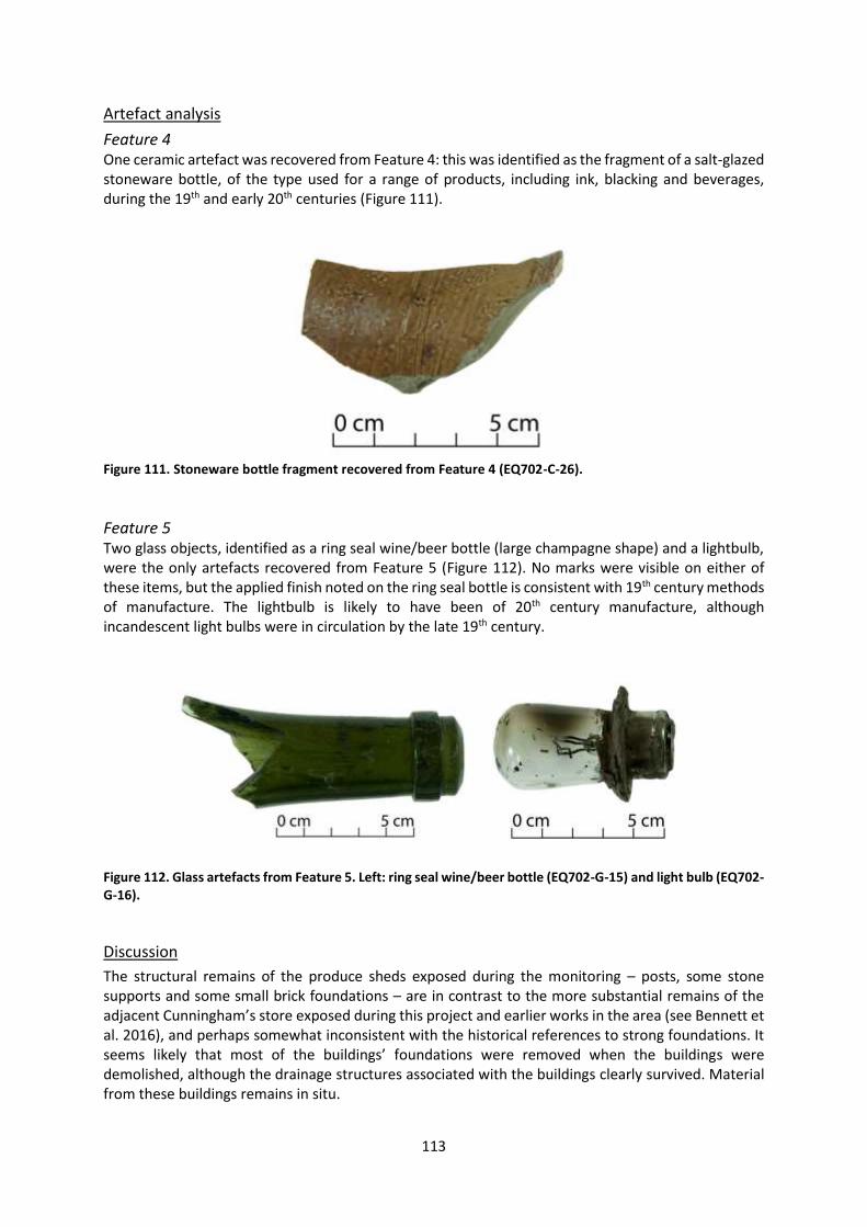
113
Artefact analysis
Feature 4 One ceramic artefact was recovered from Feature 4: this was identified as the fragment of a salt-glazed stoneware bottle, of the type used for a range of products, including ink, blacking and beverages, during the 19th and early 20th centuries (Figure 111).
Figure 111. Stoneware bottle fragment recovered from Feature 4 (EQ702-C-26).
Feature 5 Two glass objects, identified as a ring seal wine/beer bottle (large champagne shape) and a lightbulb, were the only artefacts recovered from Feature 5 (Figure 112). No marks were visible on either of these items, but the applied finish noted on the ring seal bottle is consistent with 19th century methods of manufacture. The lightbulb is likely to have been of 20th century manufacture, although incandescent light bulbs were in circulation by the late 19th century.
Figure 112. Glass artefacts from Feature 5. Left: ring seal wine/beer bottle (EQ702-G-15) and light bulb (EQ702-G-16).
Discussion
The structural remains of the produce sheds exposed during the monitoring – posts, some stone supports and some small brick foundations – are in contrast to the more substantial remains of the adjacent Cunningham’s store exposed during this project and earlier works in the area (see Bennett et al. 2016), and perhaps somewhat inconsistent with the historical references to strong foundations. It seems likely that most of the buildings’ foundations were removed when the buildings were demolished, although the drainage structures associated with the buildings clearly survived. Material from these buildings remains in situ.
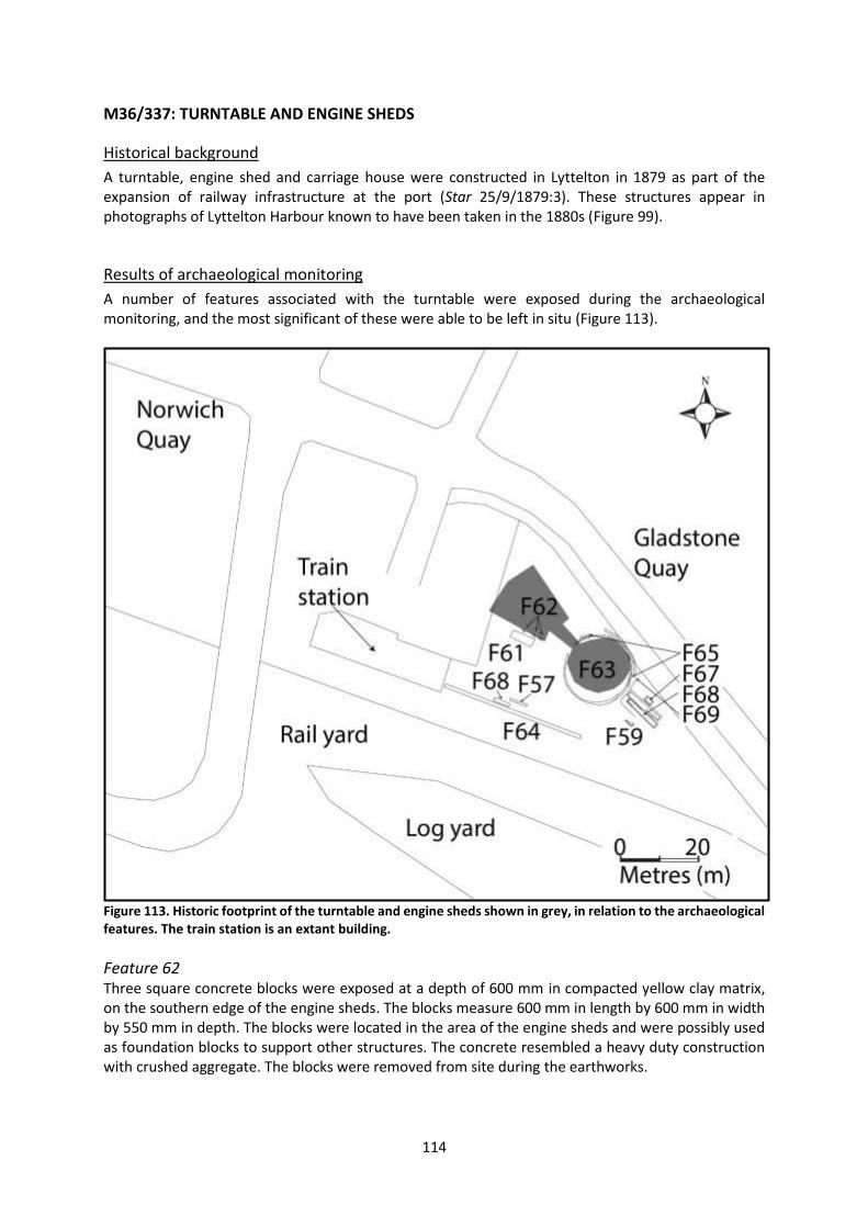
114
M36/337: TURNTABLE AND ENGINE SHEDS
Historical background
A turntable, engine shed and carriage house were constructed in Lyttelton in 1879 as part of the expansion of railway infrastructure at the port (Star 25/9/1879:3). These structures appear in photographs of Lyttelton Harbour known to have been taken in the 1880s (Figure 99).
Results of archaeological monitoring
A number of features associated with the turntable were exposed during the archaeological monitoring, and the most significant of these were able to be left in situ (Figure 113).
Figure 113. Historic footprint of the turntable and engine sheds shown in grey, in relation to the archaeological features. The train station is an extant building.
Feature 62 Three square concrete blocks were exposed at a depth of 600 mm in compacted yellow clay matrix, on the southern edge of the engine sheds. The blocks measure 600 mm in length by 600 mm in width by 550 mm in depth. The blocks were located in the area of the engine sheds and were possibly used as foundation blocks to support other structures. The concrete resembled a heavy duty construction with crushed aggregate. The blocks were removed from site during the earthworks.
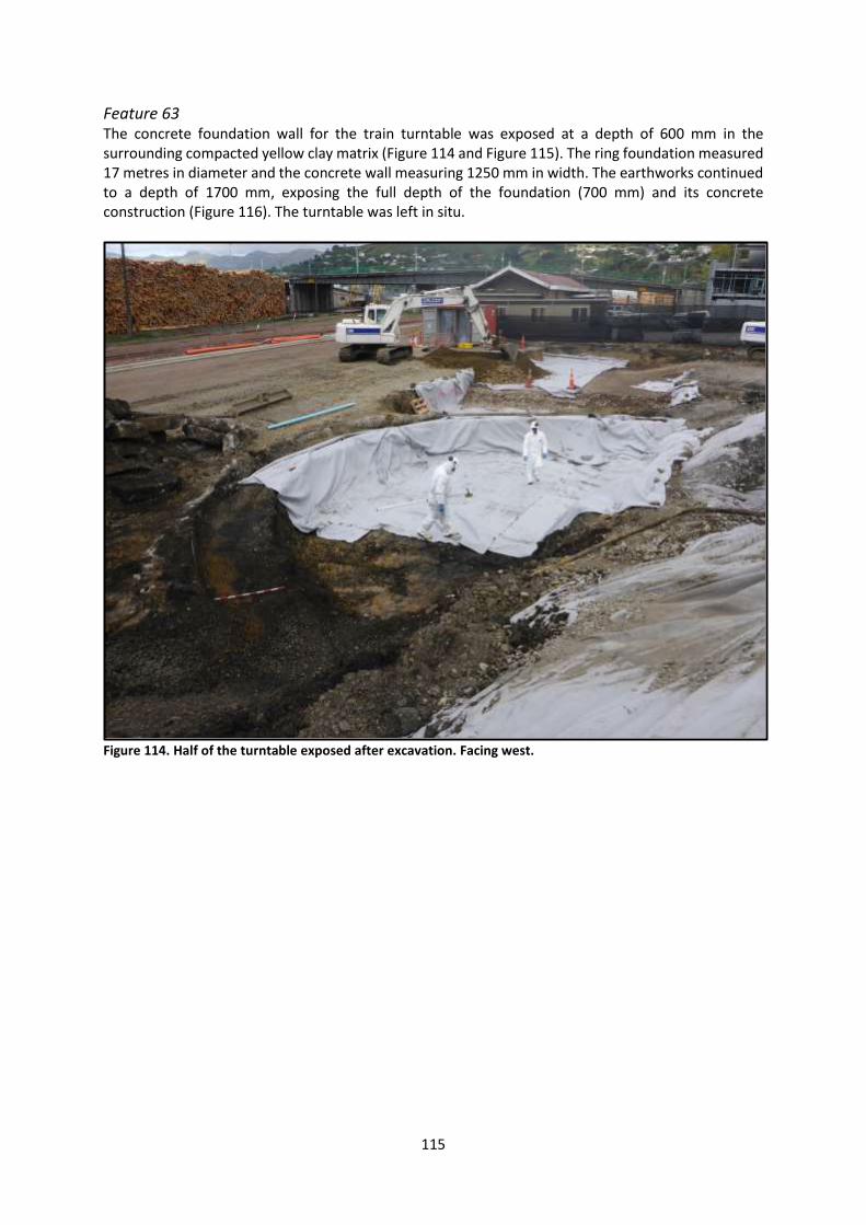
115
Feature 63 The concrete foundation wall for the train turntable was exposed at a depth of 600 mm in the surrounding compacted yellow clay matrix (Figure 114 and Figure 115). The ring foundation measured 17 metres in diameter and the concrete wall measuring 1250 mm in width. The earthworks continued to a depth of 1700 mm, exposing the full depth of the foundation (700 mm) and its concrete construction (Figure 116). The turntable was left in situ.
Figure 114. Half of the turntable exposed after excavation. Facing west.

116
Figure 115. The width of the turntable concrete wall. Facing south.
Figure 116. The concrete construction and depth of the train turntable. Facing south.

117
Feature 65 A timber beam associated with the train turntable was exposed at a depth of 450 mm (Figure 117 and Figure 118). The timber measured 2700 mm in length by 400 mm in width by 350 mm in depth. The beam contained large bolts measuring 400 mm in length, which were used to fix the timber to the top of the turntable. Rail spikes were present in the timber and were 1450 mm in distance apart. The timber beam is likely to have functioned as a capping for the concrete foundation. The timber beam was removed, although the metal bolts and fasteners remain in the location they were exposed.
Figure 117. Timber capping in relation to train turntable. Facing northeast.
Figure 118. Timber beam in situ. Facing southeast.

118
Feature 66 A second timber beam associated with the train turntable was exposed at a depth of 500 mm (Figure 119 and Figure 120). This timber beam was opposite Feature 65, although not directly opposite. The timber measured 2850 mm in length by 400 mm in width by 250 mm in depth. The beam contained large bolts measuring 400 mm in length which were used to fix the timber to the top of the turntable. There were no rail spikes in this timber capping beam. The timber beam remains in situ.
Figure 119. Timber capping beam in situ. Facing northeast.
Figure 120. Timber capping beam fixed to the top of the concrete turning circle. Facing northeast.
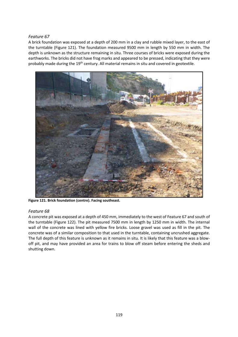
119
Feature 67 A brick foundation was exposed at a depth of 200 mm in a clay and rubble mixed layer, to the east of the turntable (Figure 121). The foundation measured 9500 mm in length by 550 mm in width. The depth is unknown as the structure remaining in situ. Three courses of bricks were exposed during the earthworks. The bricks did not have frog marks and appeared to be pressed, indicating that they were probably made during the 19th century. All material remains in situ and covered in geotextile.
Figure 121. Brick foundation (centre). Facing southeast.
Feature 68 A concrete pit was exposed at a depth of 450 mm, immediately to the west of Feature 67 and south of the turntable (Figure 122). The pit measured 7500 mm in length by 1250 mm in width. The internal wall of the concrete was lined with yellow fire bricks. Loose gravel was used as fill in the pit. The concrete was of a similar composition to that used in the turntable, containing uncrushed aggregate. The full depth of this feature is unknown as it remains in situ. It is likely that this feature was a blow-off pit, and may have provided an area for trains to blow off steam before entering the sheds and shutting down.

120
Figure 122. Concrete pit exposed to the west of Feature 67. Facing southeast.
Feature 69 A glazed earthenware pipe was exposed at a depth of 600 mm, in close proximity to Features 67 and 68 (Figure 123). The surrounding matrix consisted of a compacted clay and rubble mixture. The pipe did not have any maker’s marks, and was 180 mm in diameter. This feature remains in situ.
Figure 123. Earthenware pipe in situ.

121
Discussion
Steam engines provided a vital link for transporting cargo between the port and Christchurch during the late 19th century and early 20th century. The port recognised this, investing in rail infrastructure. Little archaeological evidence remained of the engine shed, but the concrete foundation for the turntable was exposed during earthworks. This concrete foundation would have housed a section of rail, the length of which would have been the same as the diameter of the concrete ring. This section of rail would have rotated in the pit to turn train engines around and also to store them in the adjacent train sheds. This turntable would have been vital, not only for maintaining the fleet of steam engines but also to allow efficient and effective management of shunting, loading and unloading of rail cars.
M36/344: BRICK BARREL DRAINS
Historical background
Lyttelton’s network of brick barrel drains was probably constructed in the 1870s and 1880s for combined sewage and storm water reticulation. Storm water from Lyttelton drained through natural watercourses and channels out to the harbour (Press 25/6/1898:7). With the formation of the European settlement at Lyttelton these watercourses were used to carry household waste. Around 1867 the Canterbury Provincial Council began land reclamation on the foreshore and extended the outfall of the watercourses by way of “iron tubing across to the sea” (Press 25/6/1898:7). These cast iron pipes were laid in conjunction with the railway reclamation work undertaken in 1867 (Press 11/9/1867:2). Responsibility for the town’s drainage passed to the Lyttelton Borough Council who contracted architect Samuel Farr as town surveyor in 1871, tasked with improving the culverts for the town (Star 6/1/1871:3). Of special concern was devising a means of connecting the culverts with the outfall pipes through the reclaimed land. The Canterbury Provincial Council supplied the Borough Council with plans developed by the Provincial Engineer, George Thornton, that specified a barrel drain being the same size as the iron pipes (three foot or 0.91 metres). Farr believed that a culvert at the specified size would not be sufficiently large and was unwilling to accept the plans approved by the Provincial Council. He developed an alternative plan whereby cesspools, capable of being emptied, were formed at the junction of the culverts with the iron pipes at the width specified by Thornton. Farr’s plan was commenced with and “two of the main sewers” were completed by June 1871 (Star 13/1/1871:3, Star 1/6/1871:2). The exact location of these sewers cannot be verified, but the contractor’s work involved excavating a large area of Norwich Quay and a “main drain” was possibly laid in Winchester Street (Star 15/3/1871:2 & 26/4/1871:2). However, adequate drainage remained a persistent problem in Lyttelton with roads and private property frequently damaged by storm water (Star 8/5/1872:2, Press 12/6/1872:3 & 25/6/1873:3). In December 1872 the Borough Council was called upon by local members to obtain a grant from the Canterbury Provincial Council for improved water supply and drainage for the town (Press 5/12/1872:3). This request coincided with the introduction of the Lyttelton Harbour Works Loan Act 1872 which provided £100,000 for harbour improvements, particularly in relation to the construction of the Lyttelton tunnel and railway to the port. The specified works provided for: “Drainage of the town through the reclaimed land” and “proper provision to be made for the construction and permanent maintenance of drains” (Press 12/12/1872:3). Under this Act the drainage through the reclaimed land was renewed. In June 1873 the Public Works Office of the Provincial Council invited tenders for the construction of “brick culverts and earthenware pipe drains” for the drainage of reclaimed land at Lyttelton (Press 17/6/1873:4). A contract for the works was let in July 1873 with completion scheduled for October that year (Press 23/7/1873:3).

122
The site that is affected by this archaeological authority is probably the junction of the Canterbury Street sewer with the outfall drainage system through the reclaimed land. The 1905 drainage plan for Lyttelton describes a three foot brick sewer through sections on the eastern side of Canterbury Street from London Street to Norwich Quay, and extending through the reclaimed land (Figure 124). In 1879 a sewer, three feet in diameter was laid across Norwich Quay replacing the existing drain at this location and following the same alignment (Star 15/10/1879:4, Press, 31/10/1879:3). A drain across Norwich Quay was identified by the Council’s Foreman of Works as necessary to complete the drainage of gullies in the town in order to “carry off the storm water from the different roads” (Star 17/9/1879:2).The work was overseen by the Borough Council in consultation with the Lyttelton Harbour Board and the railway engineer, so it is assumed that the work was conducted to connect each main drain with the outfall pipes through the reclaimed land (Star 15/10/1879:4, Press 20/10/1879:1). After the dissolution of the Canterbury Provincial Council in 1876, responsibility for the port, including the reclaimed land, passed to the Lyttelton Harbour Board. A protracted dispute over the state of the drains through the reclaimed land continued between the Harbour Board and the Borough Council from the 1880s to the 1900s. The Council repeatedly urged the Harbour Board to replace temporary wooden extensions of the iron outfall drains laid through the reclaimed land with permanent drains (Star 12/7/1897:4 & 17/5/1898:3, Press 11/6/1898:6 & 25/6/1898:7). The matter was finally resolved in 1906 with an agreement stipulating that the Lyttelton Borough Council immediately construct a “comprehensive sewer system” for the Borough with outfall drains outside the inner harbour and that effluent be treated by septic tanks before entering the sewer. The existing drainage system could remain in use with their existing outfall through the reclaimed land into the inner harbour for storm water only with no sewage or “house slops” to enter the drain as soon as the new sewerage system is completed (Press 25/9/1906:8). Lyttelton’s new main sewer was completed in 1909 and was at that time the greatest capital expenditure ever undertaken by the Borough Council (Star 20/4/1909:1).
Figure 124. Detail from “Plan of Drains, Water Pipes and Levels in Lyttelton”, 1905 (Christchurch City Council). Black arrow shows Canterbury Street drain between London Street and Norwich Quay.
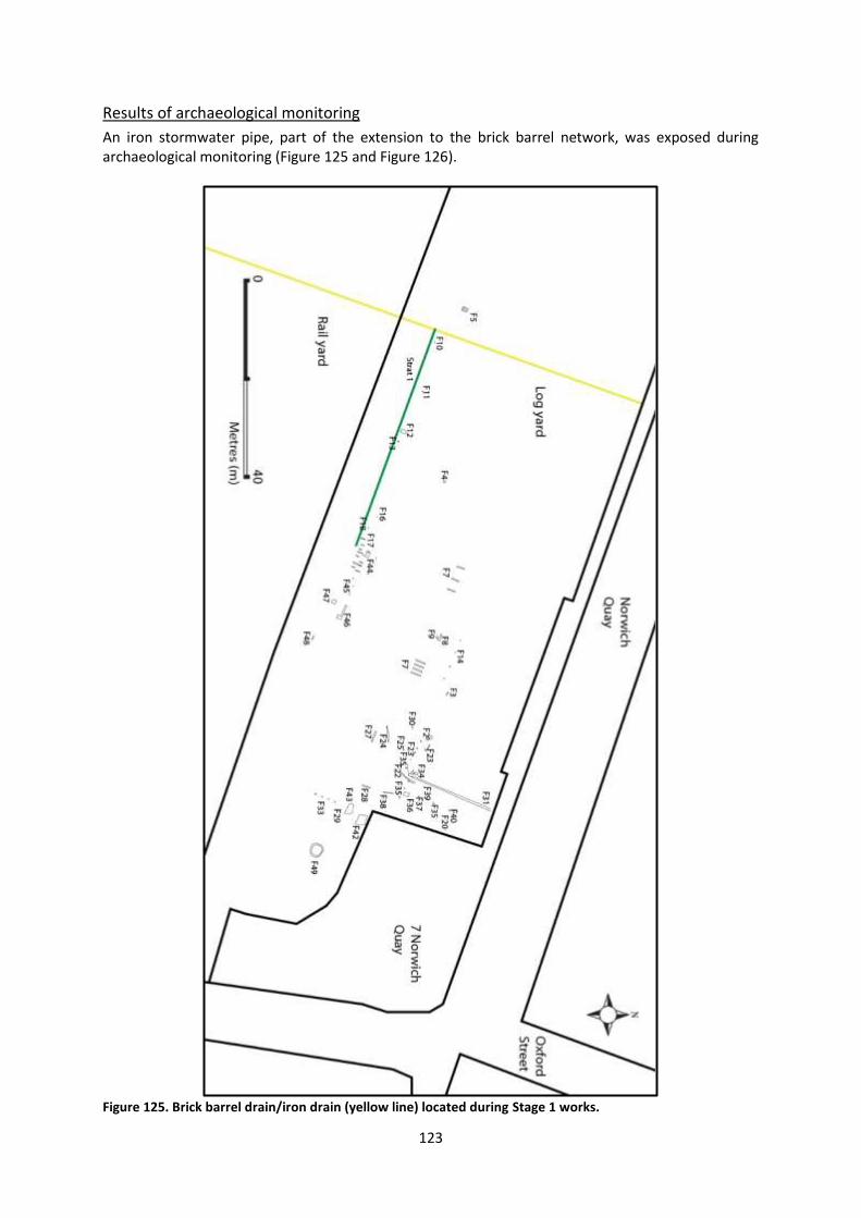
123
Results of archaeological monitoring
An iron stormwater pipe, part of the extension to the brick barrel network, was exposed during archaeological monitoring (Figure 125 and Figure 126).
Figure 125. Brick barrel drain/iron drain (yellow line) located during Stage 1 works.
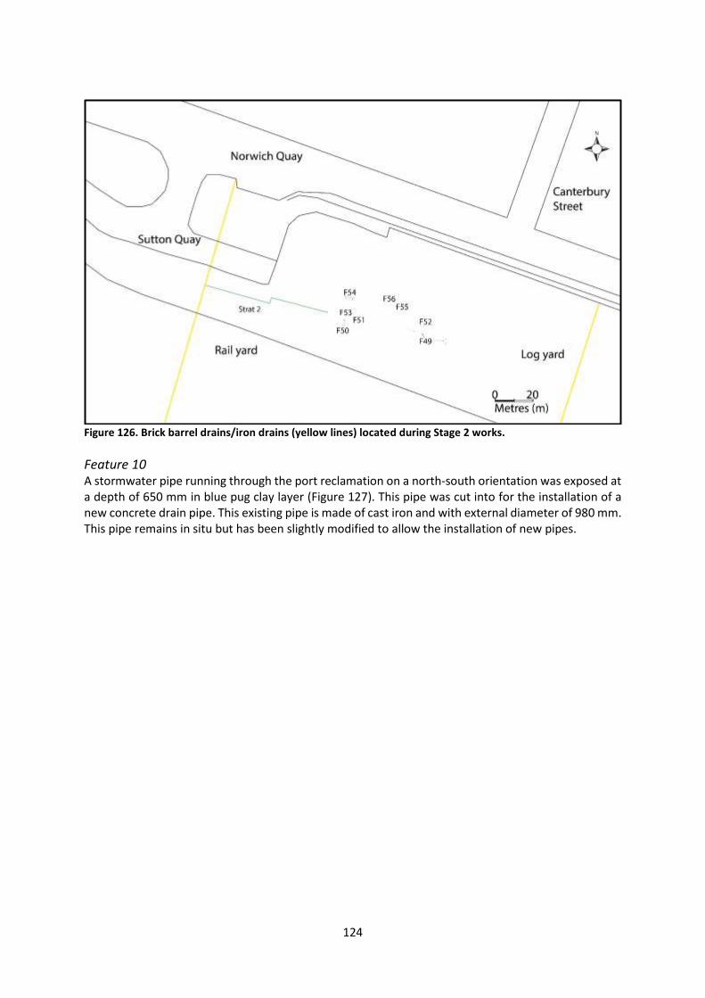
124
Figure 126. Brick barrel drains/iron drains (yellow lines) located during Stage 2 works.
Feature 10 A stormwater pipe running through the port reclamation on a north-south orientation was exposed at a depth of 650 mm in blue pug clay layer (Figure 127). This pipe was cut into for the installation of a new concrete drain pipe. This existing pipe is made of cast iron and with external diameter of 980 mm. This pipe remains in situ but has been slightly modified to allow the installation of new pipes.
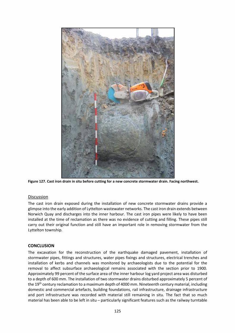
125
Figure 127. Cast iron drain in situ before cutting for a new concrete stormwater drain. Facing northwest.
Discussion
The cast iron drain exposed during the installation of new concrete stormwater drains provide a glimpse into the early addition of Lyttelton wastewater networks. The cast iron drain extends between Norwich Quay and discharges into the inner harbour. The cast iron pipes were likely to have been installed at the time of reclamation as there was no evidence of cutting and filling. These pipes still carry out their original function and still have an important role in removing stormwater from the Lyttelton township.
CONCLUSION
The excavation for the reconstruction of the earthquake damaged pavement, installation of stormwater pipes, fittings and structures, water pipes fixings and structures, electrical trenches and installation of kerbs and channels was monitored by archaeologists due to the potential for the removal to affect subsurface archaeological remains associated with the section prior to 1900. Approximately 99 percent of the surface area of the inner harbour log yard project area was disturbed to a depth of 600 mm. The installation of two stormwater drains disturbed approximately 5 percent of the 19th century reclamation to a maximum depth of 4000 mm. Nineteenth century material, including domestic and commercial artefacts, building foundations, rail infrastructure, drainage infrastructure and port infrastructure was recorded with material still remaining in situ. The fact that so much material has been able to be left in situ – particularly significant features such as the railway turntable

126
– is an excellent outcome of this project. Based on the results of this work, it is likely that archaeological material will be encountered in the reclamation between a depth of 600 mm below the current surface and 4000 mm. This depth range, however, could change with the site’s contour and the history of use/modification of a given area. The site record forms for the archaeological sites described in this report have been updated.
Assessment of the significance of the artefact assemblage Although the artefact material recovered from the inner harbour log yard is relatively scarce, with most of the assemblages consisting of small quantities of artefacts, the context in which they were found makes them significant. The wide variety of historical activity represented by the material, from possible domestic life and opportunistic discard to land reclamation, the construction of the seawall, warehouses and bond stores and the railway, is not only unusual in a regional and national context, it provides a previously unknown window into the material signature of the historic landscape of the Lyttelton port. As a whole, the assemblage is considered to be of medium-high significance, but this may change in future if any other material is recovered from the site (Table 27). Table 27. Significance of artefact assemblage recovered from the inner harbour log yard, according to standard archaeological criteria.
Criteria Value
Rarity Medium-high. Although some of the material is typical of 19th and early 20th century artefacts, the date ranges and unusual historical and archaeological context are unusual in a regional and national context.
Context Medium-high. The association of the material with both land reclamation and activity at the Lyttelton port provides a significant and unusual archaeological and historical context for the assemblage.
Condition Low-medium. The artefacts are fragmentary, although a reasonable level of preservation is noted on some of the fasteners and timber samples.
Information potential
Medium. The assemblage has the potential to inform us about rubbish disposal practices and discard behaviours in the context of land reclamation, the construction of port infrastructure and associated buildings, and the construction or maintenance of ships. This potential will grow as more material is recovered from the site and through comparisons with similar historic landscapes in New Zealand and elsewhere in the world.
Cultural associations
None known.
Amenity value Medium. Although lacking in aesthetic values, the material found in the inner harbour log yard may have value in communicating the heritage of the port landscape to both the Lyttelton and wider communities.

127
REFERENCES
Anderson, A., 1968. The Archaeology of Mass-Produced Footwear. Historical Archaeology, Vol. 2: 56-65.
ArchSite, 2014. M36/220. New Zealand Archaeological Association, Dunedin. Archives New Zealand, 1855. Letter from A. J. Alport to Provincial Secretary. R22185163, CAAR-19936-
CH287-CP7-ICPS1201/1855.
Beaumont, L., M. Carter and J. Wilson, 2014. Banks Peninsula: contextual historical overview and thematic framework. Unpublished report for Christchurch City Council. June.
Bennett, K., Dickson, C. and Whybrew, C., 2016. Lyttelton Port brick barrel drain (M36/310 and M36/344), Lyttelton: Report on archaeological monitoring. Unpublished report for City Care.
British Stainless Steel Association, 2016. The Discovery of Stainless Steel. [online] Available at http://www.bssa.org.uk/about_stainless_steel.php?id=31 [Accessed October 2016].
Burgess, R., 2009. “Lyttelton Township Historic Area”. Unpublished report for New Zealand Historic
Places Trust.
Byles, T., 1992, Reston's Hotel, The History of the Lyttelton Gaol. Christchurch.
Canterbury Maps [online], Environment Canterbury. Available at http://canterburymaps.govt.nz/.
Canterbury Provincial Council, 1867. Journal of proceedings of the Provincial Council, Session 27, 1866-67.
Carter, M., 2014a. Lyttelton Port of Christchurch (LPC) Reconstruction: An Archaeological Assessment. Unpublished report for Lyttelton Port of Christchurch, August.
Carter, M., 2014b. Lyttelton Port of Christchurch (LPC) Inner Harbour Log Yard: An Archaeological Assessment. Unpublished report for Lyttelton Port of Christchurch, October.
Cottrell, W., 2006. Furniture of the New Zealand Colonial Era: An Illustrated History 1830-1900. Reed Publishing, Auckland.
De Ruyter, J., 2006. Lyttelton Stormwater Barrels: Stage 1 Report. Review of CCTV Survey. Unpublished report for Christchurch City Council. Opus International Consultants Ltd., November.
Dobson, E., 1864. Report upon the proposed Lyttelton terminus of the Lyttelton and Christchurch railway. Journal of proceedings of the Provincial Council, Session 32.
Dodd, A. and Watson, K., 2012. 7 Norwich Quay, Lyttelton: Report on archaeological monitoring. Unpublished report for CERA.
Evening Post. [online] Available at www.paperspast.natlib.govt.nz.

128
Garland, J., Webb, K. J., Haley, J. and Bone, K., 2015. The Music Centre, 150, 154 and 156 Armagh Street: Report on Archaeological Investigations, Vol. 1. Unpublished report for The Music Centre.
Godden, G., 1991. Encyclopaedia of British Pottery and Porcelain Marks. Crown Publishers, New York. Illinois Glass Catalogue, 1906. [online] Available at http://www.sha.org/bottle/igco_1906.htm.
[Accessed April 2016] Lindsey, B., 2016. Historic Glass Bottle Identification and Information Website. [online] Available at:
www.sha.org/bottle.
Lyttelton Times [online]. Available at http://paperspast.natlib.govt.nz.
Macdonald, G. R., 1952-64. Macdonald Dictionary of Canterbury [online]. Canterbury Museum. Available at http://collection.canterburymuseum.com/search.do?highlight=17
McCarthy, M., 2005. Ships’ Fastenings: From Sewn Boat to Steamship. Texas A & M University Press, Texas.
McGuinness, S., 2013. PlanetGeog: History Written in Ink. Trinity College, Dublin. [online] Available at
https://planetgeogblog.wordpress.com/2013/06/17/history-written-in-ink. [Accessed May 2015]
Middleton, A. 2005, 'Nail Chronology: The Case of Te Puna Mission Station', Australasian Historical
Archaeology, vol. 23, pp. 55-62. New Zealand Electoral Roll, 1853-1981 [online]. Available at http://home.ancestry.com.au/.
New Zealand Historic Places Trust (NZHPT), 2003. ‘Forbes’ Store 17 Norwich Quay, Lyttelton’, Unpublished report for New Zealand Historic Places Trust. Available at https://quakestudies.canterbury.ac.nz/store/object/728?id=17011&view=media.
Otago Witness. [online] Available at www.paperspast.natlib.govt.nz.
Pierre, W. A., 1964. Canterbury Provincial Railways: Genesis of the N.Z.R. System. Wellington: The New Zealand Railway and Locomotive Society Inc.
Plowman, K., 1941. “A history of the Port of Lyttelton, 1848-1855”. Thesis presented for the degree of
Master of Arts and Honours. Christchurch: University of Canterbury.
Press [online]. Available at http://paperspast.natlib.govt.nz.
Price, J., 2006. Archaeological Assessment for Brick Stormwater Barrel Drains, Lyttelton. Draft, version 4. Unpublished report for Christchurch City Council. Opus International Consultants Ltd., November.
Rice, G. W., 2004. Lyttelton: Port and Town. An Illustrated History. Christchurch: Canterbury University Press.
Samford, Patricia M., 1997. Response to a market: Dating English underglaze transfer‐printed wares. Historical Archaeology 31 (2): 1‐30.
129
Scotter, W. H., 1968. A History of Port Lyttelton. Lyttelton Harbour Board, Christchurch. Sheffield Libraries, Archives and Information, 2011. Archives and Sheffield Local Studies Library:
Cutlery and Silverware Companies. [online] Available at: https://www.sheffield.gov.uk/libraries/archives-and-local-studies/collections/cutlery.html [Accessed October 2016].
Smith, I., Middleton, A., Garland, J. and Russell, T., 2014. Excavations at the Hohi Mission Station,
Volume 2: The 2013 Excavations. University of Otago Studies in Archaeology, No. 26. Department of Anthropology and Archaeology, Otago, New Zealand.
Star [online]. Available at http://paperspast.natlib.govt.nz.
The Transferware Collector’s Club, 2016. [online] Available at http://www.transcollectorsclub.org/ [Accessed October 2016].
Watson, J. D., 1962. The First 100 years: Municipal Government in Lyttelton: Lyttelton Borough
Council

130
APPENDIX: METHODS OF ARTEFACT ANALYSIS
All data relating to artefacts was entered into a Microsoft Excel spreadsheet. Photographs were taken of notable, interesting and/or dateable artefacts, or artefacts crucial to understanding this site.
Dating: the TPQ method
Ceramic, glass and metal artefacts were commonly embossed or printed with information concerning the manufacture of the vessel or the product the vessel contained. These manufacturers can often be identified and the period of their operation dated. The specific sources used for this process are discussed above for each material category. This information allows for the calculation of a terminus post quem (limit after which) for each feature that is associated with a dated artefact. A terminus post quem (TPQ) is the earliest date at which an archaeological feature could have been deposited. It is derived from the date range of the youngest artefact in the feature. For example, if a manufacturer identified on a ceramic vessel is known to have operated between 1865 and 1880, and this is the latest date range identified in the feature, the TPQ for that feature is 1865.
Establishing a TPQ is useful because it can be used to associate deposition with a specific period of a site’s occupation. However, it should be emphasised that the TPQ is the earliest possible date for a feature, not the definite date at which deposition occurred. The time between the manufacture and disposal of an artefact must be taken into account. Various factors influence this period. For example, a ceramic vessel is likely to proceed through a number of stages between creation and disposal. These include the time is takes for a vessel to be packed and processed in Britain, then shipped to New Zealand, and then more time in retail before its eventual purchase. After this process, the vessel was most likely used for a period of time before its disposal. This period is termed a vessel’s ‘use-life’. Therefore, it could be many years between the date at which a vessel was produced and the date at which a vessel was added to an archaeological assemblage.
Ceramic artefacts
A number of references were consulted during the analysis of the ceramic assemblage. Brooks (2005) was the principle reference used for the analysis of material ware, form and decorative technique. Samford (1997) was consulted in relation to decorative patterns and colours and internet resources such as The Potteries website were also utilised. Maker’s marks were identified using Godden (1991) and The Potteries website. These resources contribute to the internal database maintained by Underground Overground Archaeology Ltd which records both identified ceramic maker's marks and patterns recovered from previous archaeological sites in Canterbury.
Ceramics were analysed according to a standard set of attributes and the specific categories are listed below. Some of these attributes and categories have been removed from the spreadsheets in Appendix 2 due to the constraints of printing on an A4 page. The columns left out were those in which no data was entered during the analysis, or where the data was not crucial to this report. Photographs were taken of all unidentified ceramic patterns and have been retained on file. These are available on request.
Bag ID Material Quantity Decoration General information
Site Body type NISP Technique Notes Code Glaze MNI Colour References Box number Ware Pattern name/motif Photo number Bag number Function Maker's mark Provenance Form Portion

131
Faunal material
Methods of analysing the faunal material drew on those outlined in Watson (2000). The faunal material was identified to taxonomic category and, where possible, mammal and bird bones were identified to species. Underground Overground Archaeology holds a reference collection of European mammal bones, and the bird bone reference collection at the Canterbury Museum was used to identify bird bones.
A MNE (minimum number of elements) was generated from the NISP (number of individual specimen present). The attributes recorded during the analysis of the faunal material are listed below and include skeletal details, taphonomic processes and, where possible, any butchery marks on the material were recorded. Minimum number of butchery units (MNBU) was also recorded to represent cuts of meat targeted (Watson 2000).
Bag ID Description Detailed analysis General information
Site Species Taphonomy Notes Code Element MNBU Photo number Box number Side Bag number Portion Provenance
Glass artefacts
Glass vessels were sorted by provenance and analysed according to the process outlined in Smith (2004). This included recording glass colour, finish, base type and any marks present. Further information concerning the bottle and product manufacturers identified by marks was supplied when possible. Internet research provided the majority of this information but Donaldson et al. (1990) and Lindsey (2012) also proved useful.
Some glass vessels could be identified to type by their form or their embossing. This information identifies the original contents of the bottle. However, identification of the original contents of a bottle does not necessarily connect the occupants of a site with the consumption of that product. Reuse of glass bottles for different products was a common practice in New Zealand in the 19th century, as there was no glass bottle production in New Zealand until the 20th century. All bottles had to be imported, which resulted in a scarcity of glass containers. However, the identification of reuse in an archaeological context is difficult. As such, glass vessels are discussed in relation to their original contents. Several alcohol bottles were described by size. The size categories used are the following: small or small tall (63-75 mm base diameter), small squat (75-85 mm base diameter), large tall (75-85 mm base diameter), large squat (c. 88 m +).
Bag ID General description Quantity Manufacture Identification details
Site Colour NISP Type Embossing Code Portion MNV Marks Notes Box number Class Reference Bag number Common name Photo ID Provenance Details
Metal artefacts
Metal artefacts were analysed and recorded by their material type, form and measurements. If the artefact could not be identified by form a description of its appearance was included.
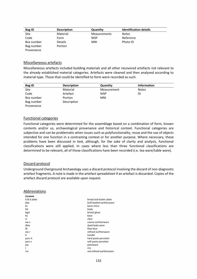
132
Bag ID Description Quantity Identification details
Site Material Measurements Notes Code Form NISP Reference Box number Details MNI Photo ID Bag number Portion Provenance
Miscellaneous artefacts
Miscellaneous artefacts included building materials and all other recovered artefacts not relevant to the already established material categories. Artefacts were cleaned and then analysed according to material type. Those that could be identified to form were recorded as such.
Bag ID Description Quantity Information
Site Material Measurement Notes Code Artefact NISP ID Box number Portion MNI Bag number Description Provenance
Functional categories
Functional categories were determined for the assemblage based on a combination of form, known contents and/or us, archaeological provenance and historical context. Functional categories are subjective and can be problematic when issues such as polyfunctionality, reuse and the use of objects intended for one function in a contrasting context or for another purpose. Where necessary, these problems have been discussed in text, although, for the sake of clarity and analysis, functional classifications were still applied. In cases where less than three functional classifications are determined to be relevant, all of those classifications have been recorded (i.e. tea ware/table ware).
Discard protocol
Underground Overground Archaeology uses a discard protocol involving the discard of non-diagnostic artefact fragments. A note is made in the artefact spreadsheet if an artefact is discarded. Copies of the artefact discard protocol are available upon request.
Abbreviations Ceramic b & b plate bread and butter plate bbe buff bodied earthenware bc bone china bd body bgst bristol glaze bs base cl clear ew-c coarse earthenware dbw dyed body ware fb flow blue ew-r refined earthenware h handle porc-h hard paste porcelain porc-s soft paste porcelain pw pearlware r rim rre red refined earthenware

133
rt rockingham type sgst salt glaze st stoneware svww Semi-vitrified whiteware ugtp underglaze transfer print unid unidentified wg white granite ww whiteware yw yellowware Faunal C complete C* complete, missing 1 epiphysis C** complete, missing 2 epiphyses P complete proximal portion of the bone P* complete proximal portion but missing the unfused epiphysis PE the unfused proximal epiphysis PS proximal shaft MS shaft DS distal shaft D complete distal portion of the bone D* complete distal portion but missing the unfused epiphysis DE the unfused distal epiphysis Glass 1pc dm one piece dip mould 2pc two piece mould 2pc w cb two piece mould with cup bottom 2pc w pb two piece mould with post bottom 3pc dm ab ag
three piece dip mould amber brown aqua green
bd body bs base bv1 cb
blake variant one cobalt
cc cl
concave colourless
cmpl complete c/s cross section cv -d
convex dark
dcc dished curved dft dished flat dm dip mould f finish fg forest green eg emerald green ft flat hs seams horizontal on shoulder hs/vb seams horizontal on shoulder, vertical on body hs/vbs seams horizontal on shoulder, vertical on body and shoulder hs/vs seams horizontal on shoulder, vertical on shoulder hz horizontal kbe kickup bell shaped kcm kickup conical with mamelon kcn kickup conical kdo kickup domed kpa kickup parabolic krc -l
kickup rounded cone light
mm machine made n neck nil og
nil seams olive green
rcb c/s round cornered blake cross section ro rounded s shoulder sc scooped st straight sts straight short

134
td tapered down td/u/bead tapered down/u-shaped groove/bead td/v/skirt tapered down/v-shaped groove/skirt tp tapered tu tapered up tus tapered up short turn-b turn marks on the body turn-l turn marks on the lip vh/hh seams vertical on heel, horizontal on heel vh/tb seams vertical on heel, transverse on base vh/tf/cb seams vertical on heel, horizontal on foot, circular on base v3h/t3f/cb seams 3 vertical on heel, 3 transverse on foot, circular on base vbs seams vertical on body and shoulder v3bs seams 3 vertical on body and shoulder vcn seams vertical complete on neck v3cn seams 3vertical complete on neck vpn seams vertical partial on neck wrench-n wrench marks on the neck Metal h head pt point s shaft

135
APPENDIX 2: ARTEFACT SPREADSHEETS
Due to the constraints of printing on an A4 page, the following artefact spreadsheets have been condensed (as noted in the footnotes for each table). For full spreadsheets please contact Underground Overground Archaeology. At the time of writing, the artefacts were stored at Underground Overground Ltd offices at 31 Stevens Street, Waltham, Christchurch.
Assemblage quantification
Table 28 and Table 29 provide an overall quantification of the log yard assemblage, according to material class and feature provenance. Table 28. Total NISP and MNE/V of artefacts from Log Yard 66, listed according to material.
Material NISP MNE/V
Ceramic 106 35
Faunal 12 10
Glass 200 92
Metal 93 92
Miscellaneous 3 2
Shoes 4 1
Smoking pipe 4 3
Total 422 235
Table 29. Total NISP and MNE/V of artefacts from Log Yard 66, listed according to feature provenance.
Feature NISP MNE/V
Feature 1 1 1
Feature 2
Feature 2a 70 68
Feature 2b 2 2
Feature 2c 7 7
Feature 4 3 1
Feature 5 2 2
Feature 7 3 3
Feature 11 4 1
Feature 16 24 15
Feature 18 3 2

136
Feature 19 2 1
Feature 22 9 5
Feature 23 1 1
Feature 23g 6 5
Feature 24 3 2
Feature 34 11 10
Feature 35
Feature 35b 1 1
Feature 35c 2 2
Feature 35d 3 1
Feature 36 174 73
Feature 42 65 22
Feature 55 1 1
Railway spikes sample 4 4
Spoil 1 1
Total 422 235
Ceramic6 Box Bag Prov. Body Glaze Ware Function Form Portion NISP MNI Tech. Colour Pattern Mark Date Notes (incl date range)
EQ702
1 F42 ew-r cl ww tea ware teacup bd/bs 7 2 ugtp blue unid: scenic/boat/geometric
large teacup/tea bowl; pattern features boat with two sails and three figures in center of base w undulating circle and diamond border w circles inside; pattern on outside of teacup features tesselated diamond pattern and unidentified scene with water and same boat in mid ground, foliage in foreground
EQ702
2 F42 ew-r cl ww table ware
dinner plate
r/bd/bs 7 1 ugtp blue Whampoa
EQ702
3 F42 ew-r cl ww table ware
dinner plate
r/bd 1 1 shell edged
blue shell edged
EQ702
4 F42 ew-r cl ww tea/table ware
cup/bowl/jug
bd 4 1 ugtp blue Whampoa
6 The following columns have been removed from this table: Site, code, photo ID, MNE.
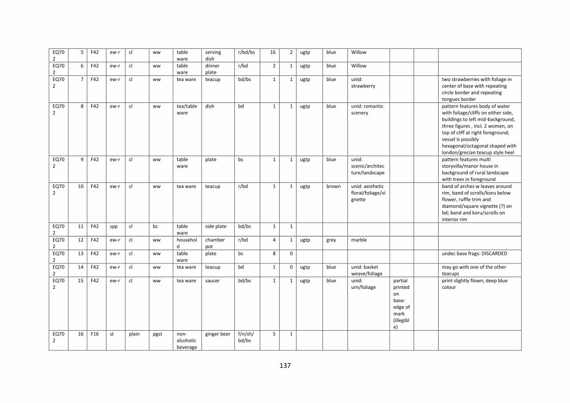
137
EQ702
5 F42 ew-r cl ww table ware
serving dish
r/bd/bs 16 2 ugtp blue Willow
EQ702
6 F42 ew-r cl ww table ware
dinner plate
r/bd 2 1 ugtp blue Willow
EQ702
7 F42 ew-r cl ww tea ware teacup bd/bs 1 1 ugtp blue unid: strawberry
two strawberries with foliage in center of base with repeating circle border and repeating tongues border
EQ702
8 F42 ew-r cl ww tea/table ware
dish bd 1 1 ugtp blue unid: romantic scenery
pattern features body of water with foliage/cliffs on either side, buildings to left mid-background, three figures , incl. 2 women, on top of cliff at right foreground; vessel is possibly hexagonal/octagonal shaped with london/grecian teacup style heel
EQ702
9 F42 ew-r cl ww table ware
plate bs 1 1 ugtp blue unid: scenic/architecture/landscape
pattern features multi storyvilla/manor house in background of rural landscape with trees in foreground
EQ702
10 F42 ew-r cl ww tea ware teacup r/bd 1 1 ugtp brown unid: aesthetic floral/foliage/vignette
band of arches w leaves around rim, band of scrolls/koru below flower, ruffle trim and diamond/square vignette (?) on bd; band and koru/scrolls on interior rim
EQ702
11 F42 spp cl bc table ware
side plate bd/bs 1 1
EQ702
12 F42 ew-r cl ww household
chamber pot
r/bd 4 1 ugtp grey marble
EQ702
13 F42 ew-r cl ww table ware
plate bs 8 0
undec base frags: DISCARDED
EQ702
14 F42 ew-r cl ww tea ware teacup bd 1 0 ugtp blue unid: basket weave/foliage
may go with one of the other teacups
EQ702
15 F42 ew-r cl ww tea ware saucer bd/bs 1 1 ugtp blue unid: urn/foliage
partial printed on base: edge of mark (illegible)
print slightly flown; deep blue colour
EQ702
16 F16 st plain pgst non-alcoholic beverage
ginger beer f/n/sh/bd/bs
5 1

138
EQ702
17 F16 ew-r cl ww tea ware saucer bd/bs 1 1 sponged blue sponged spirals
large spirals around marly/rim
EQ702
18 F16 st bristol bgst unidentified
unid bottle/jar
bd 1 1
EQ702
19 F16 spp cl bc tea ware saucer r/bd/bs 1 1 gilt gold hl bnd
EQ702
20 F16 st plain pgst unidentified
unid bottle sh/bd 1 1 relief nil unid: bnd of repeating circles around shoulder
EQ702
21 F16 ew-r nil rre gardening
flower pot r/bd/bs 2 1
EQ702
22 F22 ew-r cl ww table ware
egg cup ft/stem 1 1
EQ702
23 F22 spp cl bc table ware
bowl bs 1 1
EQ702
24 F35c st salt sgst household
penny ink cmpl 1 1
EQ702
25 F35d ew-r cl ww table ware
dinner plate
r/m/bd 3 1 ugtp blue Country Scenery
"This plate illustrates one center veiw in the David Lockhart and Co. 'Country Scenery' pattern, which was carried over from the earlier firm of Lockhart and Arthur." Incl. in their pattern list.
EQ702
26 F4 st salt sgst household/beverage
bottle bd/bs 3 1
EQ702
27 F2a ew-r cl ww tea ware teacup r/bd/handle
8 1
EQ702
28 F2a spp cl bc tea ware teacup r/bd 5 1 paint/gilt
blue/gold
banded
thick blue band around rim with hl gold border above and below
EQ702
29 F2a spp cl bc tea ware teacup bd/bs 4 1 gilt gold hl bnd
remnants of thin hl bnd on rim
EQ702
30 F2a ew-r cl ww tea/table ware
unid hollow-ware
bd 2 1 relief nil unid: foliage on shoulder
jug/teapot?
EQ702
31 F2a ew-r cl ww tea ware teacup handle 2 1 0
EQ702
32 spoil st plain pgst household
syphon ink bd/bs 1 1
impressed on heel: BLACKWOOD & CO / PATEN
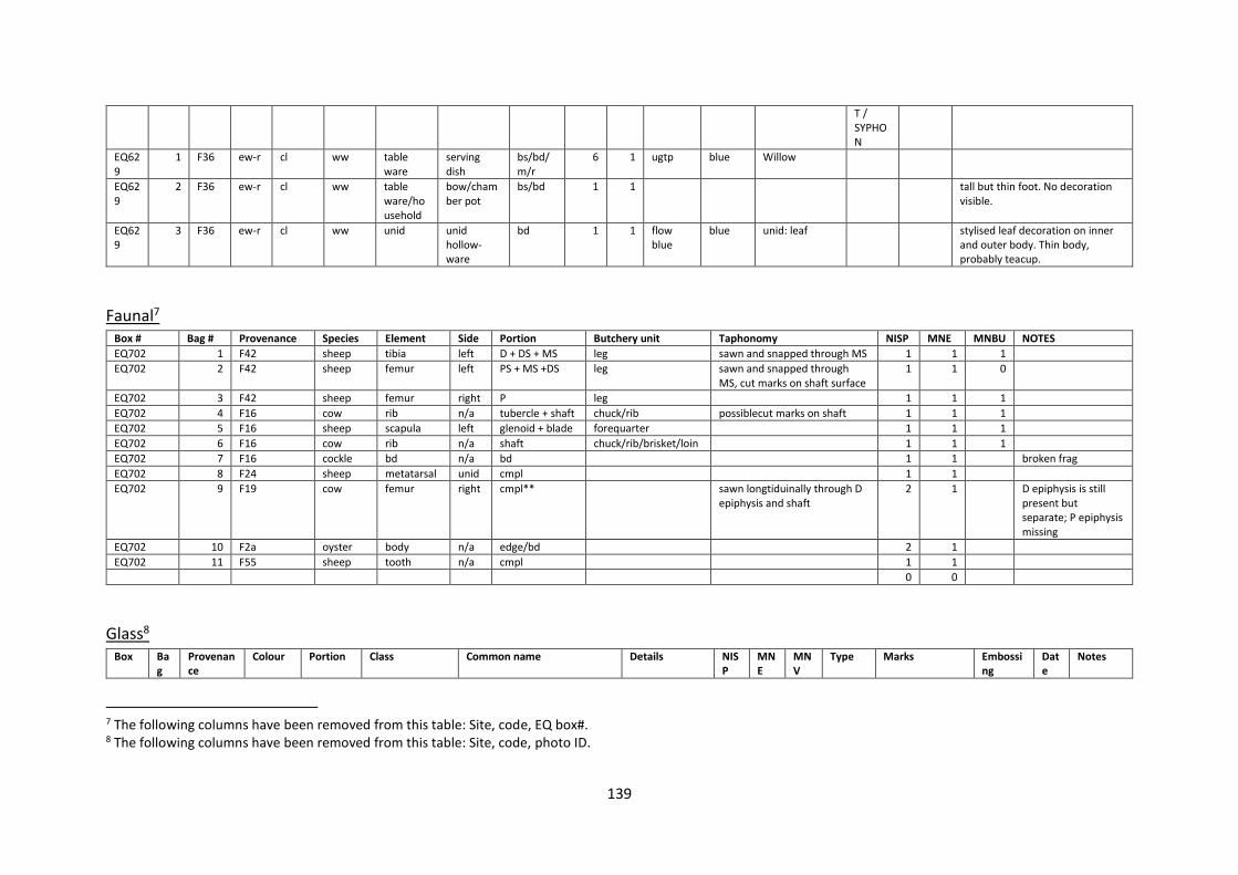
139
T / SYPHON
EQ629
1 F36 ew-r cl ww table ware
serving dish
bs/bd/m/r
6 1 ugtp blue Willow
EQ629
2 F36 ew-r cl ww table ware/household
bow/chamber pot
bs/bd 1 1
tall but thin foot. No decoration visible.
EQ629
3 F36 ew-r cl ww unid unid hollow-ware
bd 1 1 flow blue
blue unid: leaf
stylised leaf decoration on inner and outer body. Thin body, probably teacup.
Faunal7 Box # Bag # Provenance Species Element Side Portion Butchery unit Taphonomy NISP MNE MNBU NOTES
EQ702 1 F42 sheep tibia left D + DS + MS leg sawn and snapped through MS 1 1 1
EQ702 2 F42 sheep femur left PS + MS +DS leg sawn and snapped through MS, cut marks on shaft surface
1 1 0
EQ702 3 F42 sheep femur right P leg 1 1 1
EQ702 4 F16 cow rib n/a tubercle + shaft chuck/rib possiblecut marks on shaft 1 1 1
EQ702 5 F16 sheep scapula left glenoid + blade forequarter 1 1 1
EQ702 6 F16 cow rib n/a shaft chuck/rib/brisket/loin 1 1 1
EQ702 7 F16 cockle bd n/a bd 1 1
broken frag
EQ702 8 F24 sheep metatarsal unid cmpl 1 1
EQ702 9 F19 cow femur right cmpl** sawn longtiduinally through D epiphysis and shaft
2 1
D epiphysis is still present but separate; P epiphysis missing
EQ702 10 F2a oyster body n/a edge/bd 2 1
EQ702 11 F55 sheep tooth n/a cmpl 1 1
0 0
Glass8 Box Ba
g Provenance
Colour Portion Class Common name Details NISP
MNE
MNV
Type Marks Embossing
Date
Notes
7 The following columns have been removed from this table: Site, code, EQ box#. 8 The following columns have been removed from this table: Site, code, photo ID.
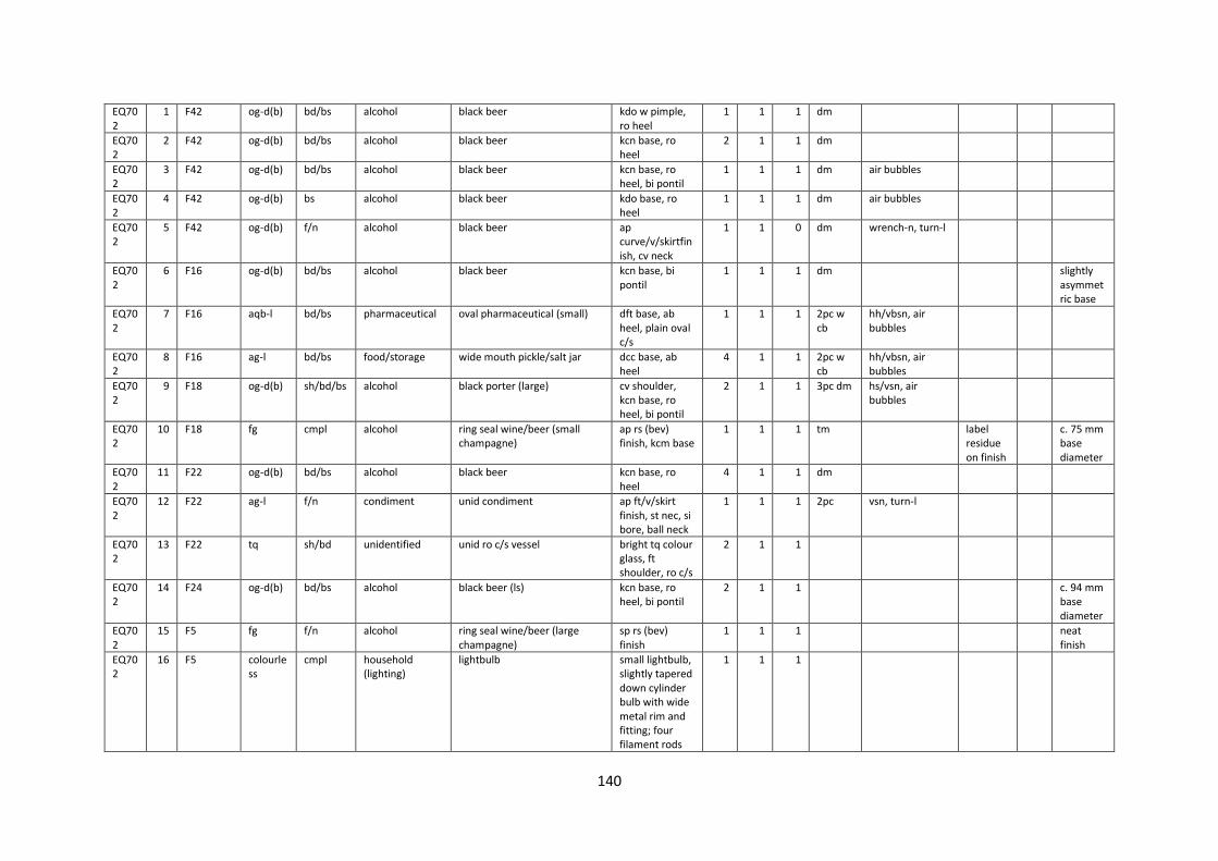
140
EQ702
1 F42 og-d(b) bd/bs alcohol black beer kdo w pimple, ro heel
1 1 1 dm
EQ702
2 F42 og-d(b) bd/bs alcohol black beer kcn base, ro heel
2 1 1 dm
EQ702
3 F42 og-d(b) bd/bs alcohol black beer kcn base, ro heel, bi pontil
1 1 1 dm air bubbles
EQ702
4 F42 og-d(b) bs alcohol black beer kdo base, ro heel
1 1 1 dm air bubbles
EQ702
5 F42 og-d(b) f/n alcohol black beer ap curve/v/skirtfinish, cv neck
1 1 0 dm wrench-n, turn-l
EQ702
6 F16 og-d(b) bd/bs alcohol black beer kcn base, bi pontil
1 1 1 dm
slightly asymmetric base
EQ702
7 F16 aqb-l bd/bs pharmaceutical oval pharmaceutical (small) dft base, ab heel, plain oval c/s
1 1 1 2pc w cb
hh/vbsn, air bubbles
EQ702
8 F16 ag-l bd/bs food/storage wide mouth pickle/salt jar dcc base, ab heel
4 1 1 2pc w cb
hh/vbsn, air bubbles
EQ702
9 F18 og-d(b) sh/bd/bs alcohol black porter (large) cv shoulder, kcn base, ro heel, bi pontil
2 1 1 3pc dm hs/vsn, air bubbles
EQ702
10 F18 fg cmpl alcohol ring seal wine/beer (small champagne)
ap rs (bev) finish, kcm base
1 1 1 tm label residue on finish
c. 75 mm base diameter
EQ702
11 F22 og-d(b) bd/bs alcohol black beer kcn base, ro heel
4 1 1 dm
EQ702
12 F22 ag-l f/n condiment unid condiment ap ft/v/skirt finish, st nec, si bore, ball neck
1 1 1 2pc vsn, turn-l
EQ702
13 F22 tq sh/bd unidentified unid ro c/s vessel bright tq colour glass, ft shoulder, ro c/s
2 1 1
EQ702
14 F24 og-d(b) bd/bs alcohol black beer (ls) kcn base, ro heel, bi pontil
2 1 1
c. 94 mm base diameter
EQ702
15 F5 fg f/n alcohol ring seal wine/beer (large champagne)
sp rs (bev) finish
1 1 1
neat finish
EQ702
16 F5 colourless
cmpl household (lighting)
lightbulb small lightbulb, slightly tapered down cylinder bulb with wide metal rim and fitting; four filament rods
1 1 1

141
inside bulb with two conducter springs between them, set into glass at base of bulb
EQ702
17 F2a amb f/n alcohol export beer crown top finish, mm
2 1 1 mm
EQ702
18 F2a fg bd alcohol ring seal wine/beer ro c/s, bd glass 1 1 1
EQ702
19 F2a colourless
r/bd table ware drinking vessel plain rim 1 1 1
EQ702
20 F2a ag-l bd structural window pane bd 1 1 1
c. 2.4 mm thickness
EQ702
21 F2b og-d(b) bd alcohol black beer bd 1 1 1
EQ702
22 F34 aqb-l bd/bs pharmaceutical oval pharmaceutical (small) dft base, ab heel, plain oval c/s
2 1 1 2pc w cb
EQ702
23 F34 ag-l bd/bs food/household square c/s bottle ro heel, dcc base, fr sq c/s
1 1 1
EQ629
1 F36 ag-d bs/bd alcohol spirit bottle ro bs c/s, dcc bs profile, ro heel, st sides
1 1 1 dm
EQ629
2 F36 ag-d bs/bd alcohol spirit bottle cv neck, flat//band finish
1 1 0 dm, a2t finish
remannts of label on neck.
EQ629
3 F36 ag bs/heel/bd
alcohol or food wide mouth pickle jar or spirit bottle
ro bs c/s, dcc/kbe bs profile, ab heel, st sides
3 1 1 h-h
probably widemouth pickle jat, but not enough of vessel.
EQ629
4 F36 ag incmpl structural window glass c1.5 mm width 5 1 1
discarded.
EQ629
5 F36 fg n alcohol wine or beer long tapered up champagne style neck
2 1 1 wrench-n "VIEUX / … AC"
discarded.
EQ629
6 F36 fg n/f alcohol ring seal wine/beer (medium) long tapered up champagne style neck
3 3 3 a2t finish
wrench-n
deep wrench marks, poorly tooled finish 30

142
mm finish width
EQ629
7 F36 fg n/f alcohol ring seal wine/beer (large) long tapered up champagne style neck (large)
3 3 3 a2t finish
wrench-n
33 mm finish width
EQ629
8 F36 fg n/f alcohol ring seal wine/beer (large) ro bs c/s, kcm bs profile, ro heel, st sides
8 3 0 turn-m
EQ629
9 F36 fg n/f alcohol ring seal wine/beer (medium) ro bs c/s, kcm bs profile, ro heel, st sides
3 3 0 turn-m
72 mm bs profile
EQ629
10 F36 fg f alcohol unid flat/v/flat finish 1 1 0 a2t finish
31 mm finish width. Like a double ring seal bottle - maybe parrt of "Vieux" bottle. Poorly tooled finish.
EQ629
11 F36 eg-d n/f alcohol wine, beer or spirit bottle st neck, flat/v/skirt finish
1 1 1 a2t finish
wrench-n
EQ629
12 F36 og-d bs/bd alcohol wine/beer ro bs c/s, kcm bs profile, ro heel, st sides
2 1 1 turn-m
EQ629
13 F36 og-d bs/bd alcohol case gin (small)
3 3 3 dm embossed cross covering bottom of base.
60 mm base width
EQ629
14 F36 og-d bs/bd alcohol case gin (large)
12 8 8
69-71 mm base width
EQ629
15 F36 og-d bd alcohol case gin
5 1 0
EQ629
16 F36 og-d sh/n alcohol case gin (large) flat shoulder, st neck
1 1 0
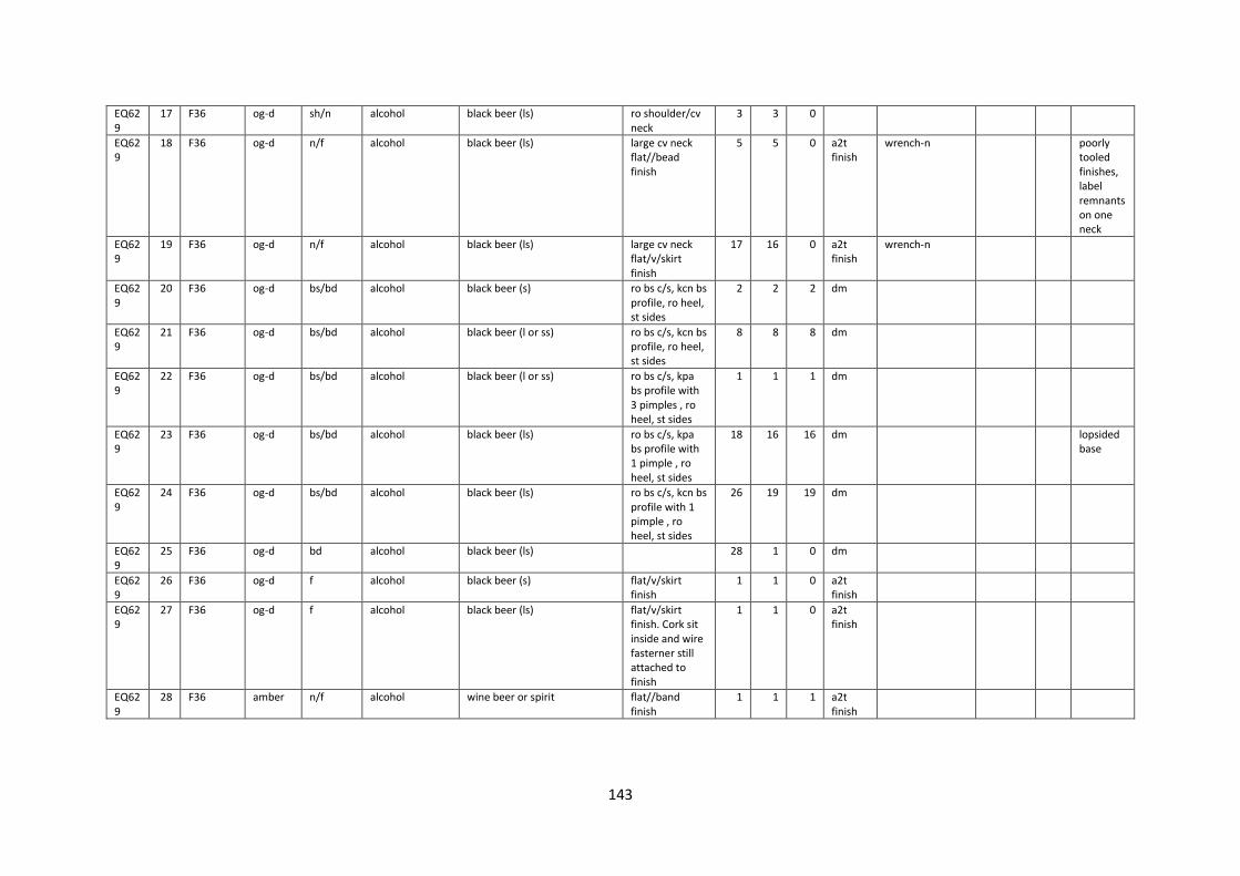
143
EQ629
17 F36 og-d sh/n alcohol black beer (ls) ro shoulder/cv neck
3 3 0
EQ629
18 F36 og-d n/f alcohol black beer (ls) large cv neck flat//bead finish
5 5 0 a2t finish
wrench-n
poorly tooled finishes, label remnants on one neck
EQ629
19 F36 og-d n/f alcohol black beer (ls) large cv neck flat/v/skirt finish
17 16 0 a2t finish
wrench-n
EQ629
20 F36 og-d bs/bd alcohol black beer (s) ro bs c/s, kcn bs profile, ro heel, st sides
2 2 2 dm
EQ629
21 F36 og-d bs/bd alcohol black beer (l or ss) ro bs c/s, kcn bs profile, ro heel, st sides
8 8 8 dm
EQ629
22 F36 og-d bs/bd alcohol black beer (l or ss) ro bs c/s, kpa bs profile with 3 pimples , ro heel, st sides
1 1 1 dm
EQ629
23 F36 og-d bs/bd alcohol black beer (ls) ro bs c/s, kpa bs profile with 1 pimple , ro heel, st sides
18 16 16 dm
lopsided base
EQ629
24 F36 og-d bs/bd alcohol black beer (ls) ro bs c/s, kcn bs profile with 1 pimple , ro heel, st sides
26 19 19 dm
EQ629
25 F36 og-d bd alcohol black beer (ls)
28 1 0 dm
EQ629
26 F36 og-d f alcohol black beer (s) flat/v/skirt finish
1 1 0 a2t finish
EQ629
27 F36 og-d f alcohol black beer (ls) flat/v/skirt finish. Cork sit inside and wire fasterner still attached to finish
1 1 0 a2t finish
EQ629
28 F36 amber n/f alcohol wine beer or spirit flat//band finish
1 1 1 a2t finish

144
Metal9 Box # Bag # Provenance Material Class Form Details Portion Measurements NISP MNI Date Notes
EQ702 1 F35c ferrous/timber fastener wrought nail/timber
sq c/s, unid head (still in timber), 2-sided taper, clenched at tip
cmpl c. 10.35 mm shaft width, c. 125 mm height
1 1
EQ702 2 F35b ferrous fastener spike (rod) unid head (shallow rim), bent rod, taper at one end to chisel point
cmpl c. 16.5 mm shaft diameter, c. 253 mm length
1 1
EQ702 3 F23g ferrous fastener spike (rod) flattened head, ro c/s rod/shaft, chisel point, bent in shaft
h/s/pt c. 247 mm length, c. 15.8 mm diameter 3 2
EQ702 4 F23g ferrous fastener spike wrought?; rt c/s, unid round head, 2-sided taper, chisel pt
cmpl c. 156 mm length/height, c. 11.2 mm shaft width, c. 24 mm head width
1 1
EQ702 5 F23g ferrous fastener spike wrought?; sq c/s, unid square head, 4-sided taper,
cmpl
1 1
EQ702 6 F7 ferrous fastener spike wrought?; brad head (protrudes to one side and tapers down to meet top of shank), shank tapers to chisel point
cmpl? c. 28 mm head width, c. 17 mm shaft width at top; c. 12 mm point width, c. 8.4 mm thickness, c. 128 mm spike height
3 3
EQ702 7 F2a ferrous fastener screw bolt round head at one end, sq c/s shaft, thick sq head at other end, screw thread on shaft at sq nd
cmpl c. 84 mm bolt length, c. 28.6 mm circular head diameter, c. 20 mm square head width, c. 13 mm square head width
1 1
EQ702 8 F2a ferrous fastener screw bolt round head at one end, sq c/s shaft, thick sq head at other end, screw thread on shaft at sq nd
cmpl c. 77 mm bolt length, c. 19 mm head diameter, c. 16 mm square head, c. 9 mm shaft thickness
1 1
EQ702 9 F2a ferrous fastener screw bolt round head at one end, sq c/s shaft, thick sq head at other end, screw thread on shaft at sq nd
cmpl c. 57 mm bolt length, c. 6.5 mm shaft thickness, c. 15 mm circular head diameter, c. 12 mm square head
2 2
EQ702 10 F2a ferrous fastener screw bolt round head at one end, sq c/s shaft, thick sq head at other end, screw thread on shaft at sq nd
cmpl c. 53 mm bolt length, c. 18 mm cicular head diameter, c. 15.6 mm square head width
1 1
EQ702 11 F2a ferrous fastener screw bolt round head at one end, sq c/s shaft, thick sq head at other end, screw thread on shaft at sq nd
cmpl c. 36 mm bolt length, c. 9.7 mm shaft daimeter, c. 16.5 mm head diameter, c. 15 mm square head width
1 1
EQ702 12 F2a ferrous fastener screw bolt round head at one end, sq c/s shaft, thick sq head at other end, screw thread on shaft at sq nd
cmpl c. 32 mm length, c. 16.5 mm circular head diameter, c. 8 mm diameter, c. 15 mm square head width
1 1
EQ702 13 F2a ferrous fastener screw bolt round head at one end, hexagonal c/s shaft, thick sq nut at other end, screw thread on shaft at sq nd
c. 51.5 mm length, c. 21 mm hexagonal width, c. 22 mm square head width
1 1
EQ702 14 F2a ferrous fastener spike circular ro head, sq c/s (?) h/s c. 85 mm length (incmpl), c. 12 mm shaft diameter/width
1 1
9 The following columns have been removed from this table: Site, code, Photo ID.

145
EQ702 15 F2a ferrous fastener nail (cut) ro rose head?; cut rt c/s, 2-sided taper, chisel point
cmpl c. 108 mm length, c. 8 mm shaft width, c. 5 mm shaft thickness
1 1
EQ702 16 F2a ferrous fastener nut circular washers of varying sizes cmpl c. 12.5 mm bore diameter, c. 30 mm diameter (largest)
15 15
EQ702 17 F2a ferrous fastener nut hexagonal washers of varying sizes cmpl c. 25 mm diameter/width, c. 10 m bore diameter, c. 12-13 height (large); c.18.5 mm diameter, c. 7 mm bore diameter, c. 10 mm height
11 11
EQ702 18 F2a ferrous fastener screw bolt ro head, ro c/s, no taper, screw thread at end of shaft
cmpl c. 63 mm height, c. 6.5 mm shaft diameter, c. 14.5 mm head diameter
5 5
EQ702 19 F2a ferrous fastener screw bolt ro head, ro c/s, no taper, screw thread at end of shaft, bent
cmpl c. 62 mm height (bent), c. 6.8 mm shaft diameter, c. 15.11 head diameter
2 2
EQ702 20 F2a ferrous fastener screw bolt ro head, ro c/s, no taper, screw thread at end of shaft
cmpl c. 50 mm height, c. 15 mm head diameter, c. 6.1 mm shaft diameter
2 2
EQ702 21 F2a ferrous fastener screw bolt ro head, ro c/s, no taper, screw thread at end of shaft
cmpl c. 77.5 mm height, c. 7 mm shaft diameter, c. 18.5 mm head diameter
1 1
EQ702 22 F2a ferrous fastener screw bolt ro head, ro c/s, no taper, screw thread at end of shaft
cmpl c. 71 mm height, c. 16 mm head diameter, c. 7 mm shaft diameter
1 1
EQ702 23 F2a ferrous fastener screw bolt ro head, ro c/s, no taper, screw thread at end of shaft
cmpl c. 85 mm length, c. 20 mm head diameter, c. 10-11 mm shaft diameter
2 2
EQ702 24 F2a ferrous fastener screw bolt ro head, ro c/s shaft, screw thread at base of shaft, square washer stuck on end of shaft
cmpl c. 55 mm length, c. 6.3 mm shaft diameter, c. 13 mm washer width
1 1
EQ702 25 F2a ferrous fastener nail (cut) cut, rosehead, rt c/s, 2-sided taper, chisel point
cmpl c. 81 mm height, c. 10.3 mm head diameter, c. 5.3 mm shaft width
7 7
EQ702 26 F2a ferrous fastener nail (wire?) wire nail?; ro c/s, bent at tip, pt missing, ro head
cmpl c. 13 mm head diameter, c. 6.3 mm shaft thickness
1 1
EQ702 27 F2a ferrous fastener screw bolt ro head, ro c/s, screw thread at base of shaft, square nut on screw
cmpl c. 13 mm washer width 1 1
EQ702 28 F2a ferrous fastener nail (cut) cut nail, rose head, rt c/s, no taper cmpl c. 13.4 mm head diameter, c. 8 mm shaft width, c. 81 mm length
1 1
EQ702 29 F2a ferrous fastener nail (wire) ro head, ro c/s h/s c. 14 mm head diameter 2 2
EQ702 30 F2b cuprous fastener tack flat head, ro c/s with 4-sided taper facets to point
cmpl c. 21 mm height, c. 9 mm head diameter, c. 4 mm shaft diameter
1 1
EQ702 31 F2c ferrous fastener screw/lag bolt
round head, ro c/s, screw thread at end of shaft, square washer on end, bent slightly
cmpl c. 28 mm head diameter, c. 12 mm shaft diameter, c. 21 mm square width
1 1
EQ702 32 F2c ferrous fastener screw/lag bolt
round head, ro c/s, screw thread at end of shaft, square washer on end
cmpl c. 18 mm head diameter, c. 15.5 mm square washer width, c. 8.3 mm shaft diameter; 88.5 mm length
1 1
EQ702 33 F2c ferrous fastener screw/lag bolt
round head, ro c/s, no taper, screw thread on end
cmpl c. 80 mm length, c. 18 m head diameter, c. 8 mm shaft diameter
1 1
EQ702 34 F2c ferrous fastener screw/lag bolt
round head, ro c/s, no taper, screw thread on end
cmpl c. 45 mm length, c. 6 mm shaft diameter, c. 14 mm head diameter
2 2
EQ702 35 F2c ferrous fastener nail (wire) ro c/s, unid head, no taper h/s c. 6.7 mm length 1 1

146
EQ702 36 F2c stainless steel cutlery knife blade thin butter knife blade blade c. 20 mm blade width, c. 0.7 mm thickness
1 1
SHEFFIELD MADE / ENGLAND // STAINLESS // B S L
EQ702 37 F1 ferrous fastener railway spike brad head, wrought?; sq c/s, tapering to chisel point
cmpl c. 130 mm length, c. 16 mm shaft width, c. 28 mm x 38 mm head width
1 1
EQ702 38 F34 cuprous fastener nail flathead tack, ro c/s, four sided facet/taper at point, v-pt
cmpl c. 33mm height, c. 10.5 mm head diameter, c. 4.5 mm shaft diameter
1 1
EQ702 39 F34 cuprous fastener nail flathead tack, ro c/s, four sided facet/taper at point, v-pt
cmpl c. 27.5 mm height, c. 9 mm head diameter, c. 3.8 mm shaft diameter
1 1
EQ702 40 F34 lead unidentified
sq pot? sq c/s, tapering down to base, hole in center of base, square flanged rim
cmpl c. 26mm base width, c. 36 mm rim width, c. 35 mm height
1 1
EQ702 41 F34 ferrous unidentified
ring broken, half of flat metal ring bd c. 13 mm, c. 108 mm diameter, c. 6.5 mm thickness
1 1
EQ702 42 F34 ferrous fitting? plug/valve circular disc with rod protruding from center of one side and heavily rusted conglomeratio of rods/fastener from other side
cmpl c. 53 mm disc diameter, c. 76.5 mm whole length, c. 16.4 mm rod diameter, c. 7 mm thickness
1 1
EQ702 43 F34 ferrous/timber spike/timber
spike (rod) round head, ro c/s shaft, unid pt (still in timber)
cmpl c.27 mm head diameter, 16.5 mm shaft diameter, c. 262 mm (height of fragment)
1 1
EQ702 44 F34 ferrous/timber spike/timber
spike (rod) round head, ro c/s shaft, unid pt (still in timber)
cmpl c. 291 mm length (height of fragment), c. 25.5 mm head diameter, c. 16 mm shaft diameter
1 1
EQ702 45 F23 ferrous fastener spike (rod) round head, ro c/s shaft, blunt point, bent
cmpl c. 29 mm head diameter, c. 16 mm shaft diameter, c. 160 mm total length
1 1
EQ702 46 spike sample ferrous fastener railway spike brad head, sq c/s, blunt point cmpl c. 131 mm length, c. 21 mm max shaft thickness, c. 41 mm head width
4 4
Miscellaneous10 Box # Bag # Provenance Material Class Artefact Portion Description Measurements NISP MNI Date Notes
EQ702 1 F2a cork alcohol bottle cork cmpl
1 1
EQ702 2 F34 timber structural post s/pt sq/rt post c/s, sawn to form point (four sided taper)
c. 60 mm post width, c. 243 mm fragment length 1 1
EQ629 1 F36 cork bottle cork bottle cork incmpl porus thin rounded cork with st sides. 14.5 mm width, >25 mm length 1 0
10 The following columns have been removed from this table: Site, code, Photo ID

147
Clay smoking pipes11 EQ Box
Bag #
Feature
Material
Class Artefact
Type Portion
NISP
MNE
MNI
One piece/Two piece
Configuration
Bowl shape
Plane of bowl
Spur/heel
Stem Bite Measurements
Bowl
Spur
Stem
Usewear
Date
Notes
EQ702
1 F16 clay personal
smoking pipe
unknown
s-body, s-bite
1 1 1 one piece
st stem configuration
n/a n/a n/a straight
glazed
c. 5.5 mm bite diameter
stem tapers*
EQ702
2 F16 clay personal
smoking pipe
unknown
s-body
2 1 1 one piece
st stem configuration
n/a n/a n/a straight
n/a
EQ702
3 F23g clay personal
smoking pipe
unknown
s-body, s-bite
1 1 1 unid st stem configuration
n/a n/a n/a straight
raised
Footwear12 Box B
ag Provenance
Material
Class Portion
Size/wearer
Type/style
NISP
MN
Toe shape
Heel type
Lifts
Closure
Decoration
Heel Sole/insole
Upper Reinforcing
Repair
Date
Notes Measurements
EQ702
1 F11 leather
footwear
outsole, insole, upper, heel, shank
adult male
shoe/boot
4 1 medium square
n/a
n/a
n/a nil vertical attachment (pegs)
vertical attachment (pegs)
vertical attachment (pegs)
line of pegs running through ball of insole/outsole, shank attached to arch of sole
1860s?
double row of pegs around edge of soles and upper, double row in arrow shape around top of arch; single line longitudinally up
c. 257 mm length, c. 93 mm max width ball of foot, c. 52 mm arch width, c. 64 mm heel width
11 The following columns have been removed from this table: Site, code, Photo ID 12 The following columns have been removed from this table: Site, code, Photo ID
148
ball of sole;