inmarsat mini-c mobile earth station model felcom …¼cher/ime56380j_fel… · 3.1 installing...
TRANSCRIPT

INMARSAT MINI-C MOBILE EARTH STATION Model FELCOM 16
Installation Manual TABLE OF CONTENTS
SAFETY INSTRUCTIONS ............................................................................................................. i
EQUIPMENT LISTS ...................................................................................................................... ii
SYSTEM CONFIGURATION ....................................................................................................... iii
1. MOUNTING THE UNIT ............................................................................................................ 1 1.1 Antenna Unit ................................................................................................................... 1 1.2 Communication Unit ........................................................................................................ 3 1.3 AC/DC Power Supply Unit PR-240 (option) .................................................................... 3
2. WIRING ................................................................................................................................... 4 2.1 Antenna Cable Connector at the Terminal Unit ............................................................... 5
3. SETTINGS AFTER THE INSTALLATION ............................................................................... 8 3.1 Installing Software ........................................................................................................... 8 3.2 Setting the IMN (Inmarsat Mobile No.) .......................................................................... 11
4. CHANGING POWER SUPPLY SPECIFICATIONS ............................................................... 12
PACKING LISTS ....................................................................................................................... A-1
OUTLINE DRAWINGS .............................................................................................................. D-1
INTERCONNECTION DIAGRAM ............................................................................................. S-1
www.furuno.com
All brand and product names are trademarks, registered trademarks or service marks of their respective holders.


i
Confirm that the power supply voltageis compatible with the voltage ratingof the equipment.
Connection to the wrong power supplycan cause fire or equipment damage. Thevoltage rating appears on the label at therear of the communication unit.
Use the correct fuse.
Use 10 A fuse (defalt setting) for 12 VDC power supply, or replace the fuse to 5 A (supplied as spare parts) with 24 VDC.
Use of wrong fuse can result in damage to the equipment.
Keep the following compass safe distances.
Standard Steering
Antenna Unit IC-116
Communication Unit IC-216
AC/DC Power Supply UnitPR-240
SAFETY INSTRUCTIONS
Do not open the equipmentunless totally familiar withelectrical circuits andservice manual.
Only qualified personnelshould work inside theequipment.
WARNING
Turn off the power at the mains switchboard before beginning the installation. Post a sign near the switch to indicate it should not be turned on while the equip- ment is being installed.
Fire, electrical shock or serious injury can result if the power is left on or is applied while the eqiuipment is being installed.
ELECTRICALSHOCK
HAZARD
0.3 m 0.3 m
0.3 m 0.3 m
0.9 m 0.6 m
Do not approach the ra-dome closer than 60 cmwhen it is transmitting.
Microwave radiation cancause severe injury or illness.Radiation level:10 W/m at 60 cm2
CAUTION
Attach securely protectionearth to the ship's body.
The protection earth is required to the power supply to prevent electrical shock
ii
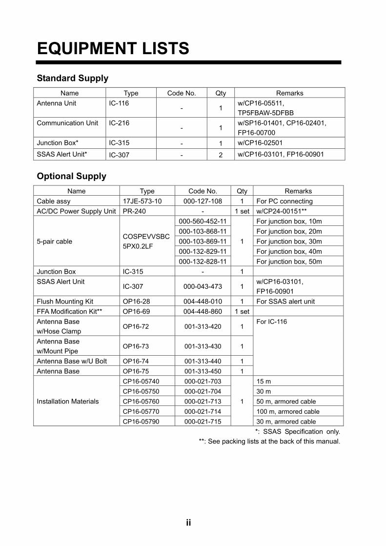
EQUIPMENT LISTS
Standard Supply
Name Type Code No. Qty Remarks
Antenna Unit IC-116 - 1
w/CP16-05511,
TP5FBAW-5DFBB
Communication Unit IC-216 - 1
w/SP16-01401, CP16-02401,
FP16-00700
Junction Box* IC-315 - 1 w/CP16-02501
SSAS Alert Unit* IC-307 - 2 w/CP16-03101, FP16-00901
Optional Supply
Name Type Code No. Qty Remarks
Cable assy 17JE-573-10 000-127-108 1 For PC connecting
AC/DC Power Supply Unit PR-240 - 1 set w/CP24-00151**
5-pair cable COSPEVVSBC
5PX0.2LF
000-560-452-11
1
For junction box, 10m
000-103-868-11 For junction box, 20m
000-103-869-11 For junction box, 30m
000-132-829-11 For junction box, 40m
000-132-828-11 For junction box, 50m
Junction Box IC-315 - 1
SSAS Alert Unit IC-307 000-043-473 1
w/CP16-03101,
FP16-00901
Flush Mounting Kit OP16-28 004-448-010 1 For SSAS alert unit
FFA Modification Kit** OP16-69 004-448-860 1 set
Antenna Base
w/Hose Clamp OP16-72 001-313-420 1
For IC-116
Antenna Base
w/Mount Pipe OP16-73 001-313-430 1
Antenna Base w/U Bolt OP16-74 001-313-440 1
Antenna Base OP16-75 001-313-450 1
Installation Materials
CP16-05740 000-021-703
1
15 m
CP16-05750 000-021-704 30 m
CP16-05760 000-021-713 50 m, armored cable
CP16-05770 000-021-714 100 m, armored cable
CP16-05790 000-021-715 30 m, armored cable
*: SSAS Specification only.
**: See packing lists at the back of this manual.
iii
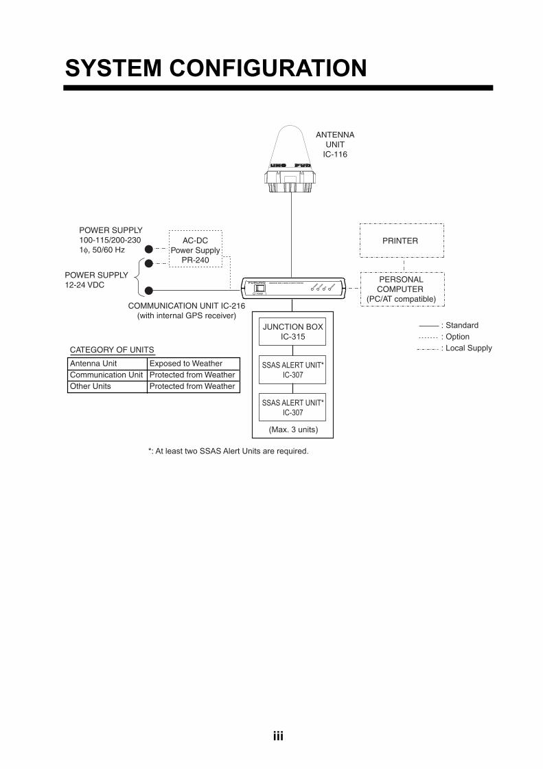
SYSTEM CONFIGURATION
Antenna Unit Exposed to WeatherCommunication Unit Protected from WeatherOther Units Protected from Weather
PERSONALCOMPUTER
(PC/AT compatible)
ANTENNAUNIT
IC-116
COMMUNICATION UNIT IC-216(with internal GPS receiver)
POWER SUPPLY100-115/200-2301φ, 50/60 Hz
: Standard: Option: Local Supply
POWER SUPPLY12-24 VDC
AC-DCPower Supply
PR-240
POWER IO
INMARSAT MINI-C MOBILE EARTH STATIONFURUNO
POWER
LOGIN
TX ERROR
PRINTER
JUNCTION BOXIC-315
SSAS ALERT UNIT*IC-307
SSAS ALERT UNIT*IC-307
*: At least two SSAS Alert Units are required.
CATEGORY OF UNITS
(Max. 3 units)

iv
This page is intentionally left blank.

1
1. MOUNTING THE UNIT
NOTICEDo not apply paint, anti-corrosive sealant or contact spray to coating or plastic parts of the equipment.
Those items contain organic solvents that can damage coating and plastic parts, especially plastic connectors.
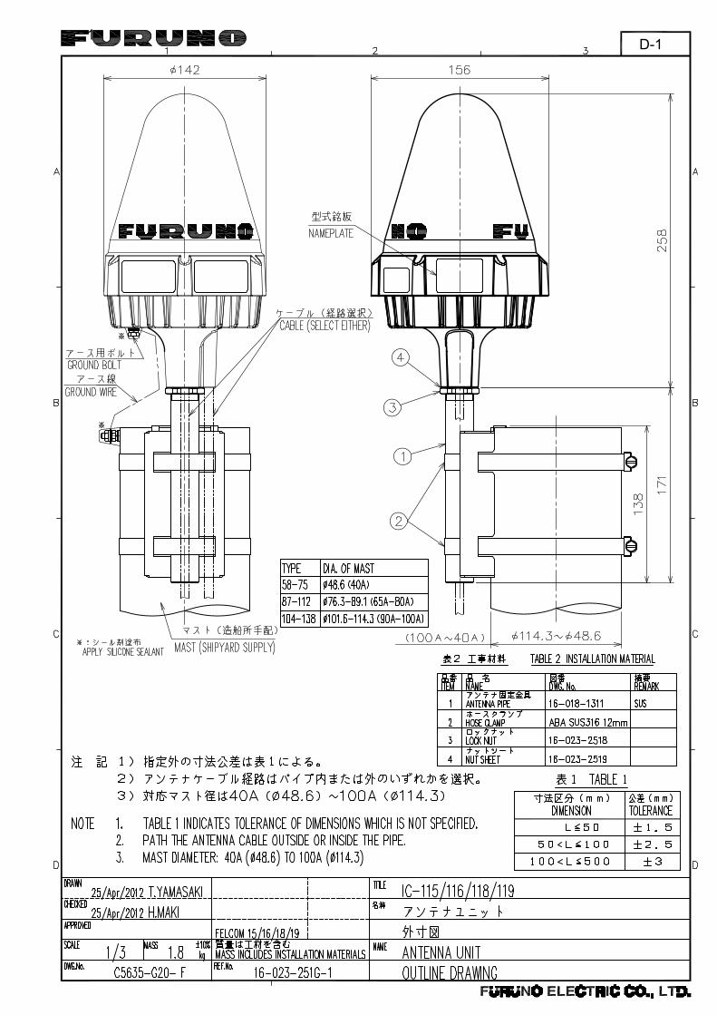
1.1 Antenna Unit Mounting Location
• There should be no interfering object within the line-of-sight to the satellite. Objects within line-of-sight to a satellite, for example, a mast may block transmission/reception. Mount the antenna unit as high as possible. This keeps it free of interfering objects and water spray. The location should be well away from a GPS antenna. A GPS receiver may be interfered by the Inmarsat C wave.
• If both Inmarsat-B or F ship earth stations are installed, separate the Inmarsat-B/F antenna at least 8 m.
• Separate the antenna unit from an S-band radar as follows:
HORIZONTAL LINE
Install above this line
PROHIBITEDZONE1.5 m
5 m
15
2 m
S-band radar
INSTALLTION ZONE
2 m
S-band radar and installation area
• The allowable vibration level as specified by Inmarsat is as shown in the table below.
Allowable vibration level
Frequency Level
2 to 10 Hz 2.54 mm Peak Amplitude
10 to 100 Hz 9.8 m/s² Peak Acceleration
• Avoid the location near funnels and stacks; smoke and soot on the radome can lower signal level.
• Separate the antenna unit 5 m from HF, VHF or 27 MHz antenna.

1. MOUNTING THE UNIT
2
Mounting
The antenna cable is available in lengths of 15 m, 30 m, 50 m and 100 m (see table below). Cable length Type Remarks
15 m (no armor) TP58A15W-RG58A/UTNC connector at both ends
30 m (no armor) TP5FBAW-5DFB 30 m (w/armor) 5D-FB-CV-NP
N connector on one end (antenna side) 50 m (w/armor) 8D-FB-CV 100 m (w/armor) 12D-SFA-LITE-CV Note 1: Do not shorten these cables. Interference can result, affecting performance. Locally prepare an antenna mast with a ground stud (M6 bolt welded to antenna mast). The distance between the stud and the earth terminal on the antenna unit should be within 340 mm, which also is the length of the supplied ground wire. Note: Use of the mounting pipe (FURUNO supply or the equivalent) is mandatory in case of FFA version. See the equipment list at the beginning of this manual for information.
Antenna base
Cable
GND terminal
GND wire
Hose clamp
M6 GND STUD(shipyard supply)
Mast (shipyard supply) Mounting pipe and antenna mast
For how to wire the antenna cable, see "Installation and Replacement of Antenna Unit", included with the antenna unit.

1. MOUNTING THE UNIT
3
1.2 Communication Unit Mounting Select the following place to mount the communication unit. • Provide sufficient ventilation.
• For maintenance and checking purpose, leave sufficient space at the sides and rear of the unit.
Use two tapping screws (4x40, supplied) to fix the communication unit. You can insert screws from the top and bottom side of the communication unit for bulkhead mounting. After the screwing, attach the cosmetic caps (2 pcs, supplied) to fixing holes to cover the screw head.
184 + 0.5
72.5 + 0.5
2- 4.5Fixing hole
Communication unit, dimensions
1.3 AC/DC Power Supply Unit PR-240 (option) Fix the unit on a table with four tapping screws (4x16).
272 + 1
100 + 1
4 - 6
AC/DC power supply unit, dimensions

4
2. WIRING
Power supply12-24 VDC
Copper strap1.2 m
Ground wireRW-4747
TP58A15W-RG58A/U, 15 mTP5FBAW-5DFB, 30 m(No armor)Connector at both ends
0.34 mFor cable w/armor
TNCP-NJ
Cable assyTPA5FB0.4NJ5FBA-5DFB0.4 m
17JE-573-10(5 m, option)
PC
This unit is shipped with 10 A fuse.Replace fuse with 5 A when using the equipment with the power supply 24 VDC.And then, attach a label for 5 A to the fuse cover on power cable.
Use of wrong fuse can result in damage to the equipment.
CAUTION
FM-C3FPS-002-035, 3.5 m
5D-FB-CV-NP, 30 m8D-FB-CV, 50 m12D-SFA-LITE-CV, 100 mConnector at one end
Connector N-P-5DFBN-P-12DSFA
N-P-8DFB(supplied, local arrange)
Junction Box IC-315
IC-307
PR-240
24 VDC
100-115V/200-230 VAC,1,50/60Hz
SSAS Alert Unit IC-307
AC/DC Power Supply Unit
At liast two SSAS Alert untis are required (Max. 3 sets)
Wiring of FELCOM 16

2. WIRING
5
2.1 Antenna Cable Connector at the Terminal Unit 5D-FB-CV-NP (30 m)
30
Cover with heat-shrink tubing and heat.
Outer Sheath
Armor
15
Nut
GasketClamp
Inner Sheath
Braided Shield
5
Washer
50
Cut braided shield here.
3.5Insulator
Core
Center Pin
Solder here.
Ring
Insulator Ring
Shell
Nut
Remove the outer sheath, armor and inner sheath by the dimensions shown.
Set the nut, washer, gasket, clamp onto cable as shown.
- Be careful not to damage the braided shield.
Fold back the braided shield onto the clamp and trim the shield as shown.
Make the length of insulator 3.5 mm and the length of the core 5 mm.- Be careful not to damage the core.
Set the center pin to the core and solder the pin from the hole in the pin.(Pull the pin with approx. 1 kg of force to check strength of solder joint.)- Be sure the solder is flush with surface of
pin.- Be sure there is no gap between center
pin and insulator. Do not push the center pin into the insulator.
- Do the soldering as quickly as possible so as not to deform the insulator.
Set the ring and insulator ring onto the cable.
Set the shell to the cable then turn the nut to tighten. (Do not tighten by turning shell.)- Use a wrench or the like to tighten the nut
securely.
How to fabricate antenna cable 5D-FB-CV-NP

2. WIRING
6
8D-FB-CV (50 m)
Outer SheathArmor Inner Sheath Shield
Dimensions in millimeters.
50 30
Cover with heat-shrink tubing and heat.
30 10
ClampNut
Gasket(reddishbrown)
Clamp
Trim shield here.
Aluminum Foil
Insulator
Trim aluminumtape foil here.
1
5
Pin
ShellClamp Nut
Solder throughthe hole.
Remove outer sheath and armor by thedimensions shown left.Expose inner sheath and shield by thedimensions shown left.
Remove insulator and core by 10 mm.
Twist shield end.
Slip on clamp nut, gasket and clamp as shownleft.
Fold back shield over clamp and trim.
Cut aluminum foil at four places, 90 from oneanother.
Fold back aluminum tape foil onto shield and trim.
Expose the insulator by 1 mm.
Expose the insulator by 5 mm.
Slip the pin onto the conductor. Solder themtogether through the hole on the pin.
Insert the pin into the shell. Screw the clampnut into the shell.(Tighten by turning the clamp nut. Do nottighten by turning the shell.)
How to fabricate antenna cable 8D-FB-CV

2. WIRING
7
12D-SFA-LITE-CV (100 m)
Outer SheathArmor Inner Sheath Shield
Dimensions in millimeters.
80 12
NutWasher
Gasket Clamp
1.8
4.5
Clamp Nut
Pin
Solder throughthe hole.
Remove outer sheath and armor by thedimensions shown left.Expose inner sheath and shield by thedimensions shown left.
Twist shield end.
Slip on clamp nut, gasket and clamp as shown left.
Expose the insulator by 1.8 mm.
Expose the core by 4.5 mm.
Slip the pin onto the conductor. Solder themtogether through the hole on the pin.
Insert the pin into the shell. Screw the clamp nut into the shell.(Tighten by turning the clamp nut. Do nottighten by turning the shell.)
How to fabricate antenna cable 12D-SFA-LITE-CV

8
3. SETTINGS AFTER THE INSTALLATION
3.1 Installing Software After installing the equipment, obtain the installation file from “Latest Software Versions” of FURUNO “Tech-Net” to install the software. 1. Turn on the PC. 2. Download “FELCOM16_VXX.XX_setup (.exe)” file from “Latest Software Versions” of
FURUNO “Tech-Net” to your desktop, and then double-click it. (XX.XX: Software version) The setup procedure begins, displaying the figure shown below.

3. SETTINGS AFTER THE INSTALLATION
9
3. Click the [Next] button.
4. Click the [Next] button.

3. SETTINGS AFTER THE INSTALLATION
10
5. Click the [Install] button and the installation begins.
6. Click the [Finish] button. The FELCOM 16 PC application shortcut is created on the desktop.
Note: To uninstall the F16 application see the operator’s manual for the PC.

3. SETTINGS AFTER THE INSTALLATION
11
3.2 Setting the IMN (Inmarsat Mobile No.) Set your IMN (Inmarsat Mobile No.) using the and PC as below. 1. Power on the communication unit and PC in order. 2. Double click [F16PC] on the screen to start the program. 3. Press the [F8] function key to show the Setup menu.
Setup
File Edit Transmit EGC Reports Logs Options Setup Position StopAlarm
1. System Setup2. Editor Setup3. Terminal Setup4. EGC Setup5. Auto Mode Setup6. E-Mail Setup7. Directories8. Configuration
Setup menu
4. Press [1] key to display the System Setup menu. Setup
9. Configuration
System Setup
01:53 02-02-25 (YY-MM-DD)
INMARSAT-CINTINTINTINT
System Date & TimeIMNMES Operation ModeNav PortActive PortMessage Output PortEGC Output PortNetwork SetupCommand Window
System Setup menu
5. Confirm that the IMN is selected, and then press the [Enter] key. The entering field appears.
6. Key in your IMN. 7. Press the [Enter] key. 8. Press the [Esc] key to escape from the entering field. 9. Press the [Enter] key. To clear the IMN, press [I] [M] [N] in order while pressing the [Alt] key down at step 6. When using the FELCOM 16 for VMS (Vessel Monitoring System), DNID (Data Network ID) has to be downloaded via the LES (Land Earth Station). This arrangement is normally done by authority of VMS.

12
4. CHANGING POWER SUPPLY SPECIFICATIONS
The AC/DC power supply unit PR-240 is shipped ready for connection to a 200-230 VAC ship’s mains. If the ship’s mains is 100 VAC-115 VAC, change the tap connection and terminal board connection as below. Attach a label supplied as accessories to the front panel according to the ship’s mains.
Ship’s mains Tap connection Terminal board Label
200-230 VAC SEL 230 V Below (a) 200-230 VAC 2.2-1.7 A 1φ 50/60 Hz
100-115 VAC SEL 115 V Below (b) 100-115 VAC 3.2-2.6 A 1φ 50/60 Hz
Remove screw and cover.
Cover
12345678
SEL115V
SEL230V
123
100-115 VAC
123
200-230 VAC(a)
(b)
AC FAIL:Connect to Alarm system.� Output Setting: Normal Open Set plug to 1 & 2 pins of J4 (Factory setting) Normal Close Set plug to 2 & 3 pins of J4
AC Power Switch(When connecting DC input, note that the DC power is supplied even though this switch is turned off.)
Heat sink
Tap connection (Pull out to disconnect.)
Front panel
Terminal board
GreyBlack
Grey
Black
Attach appropriate label.Front panel
CoilRelay
3
12J4
Note: The DC output load must be less than 8A.

NAME
OUTLINE
Q'TY
DESCRIPTION/CODE №
PA
CK
IN
G
LI
ST
16AL-X-9854-4
FELCOM16-*
1/1
NAME
OUTLINE
Q'TY
DESCRIPTION/CODE №
ユニ
ット
UNIT
アンテナユニット一式
ANTENNA UNIT
1IC-116
000-043-555-00
通信制
御ユニット
COMMUNICATION UNIT
1
**
IC-216-*
000-043-542-00
予備
品SPARE PARTS
予備品
SPARE PARTS
1SP16-01401
004-439-530-00
付属
品ACCESSORIES
付属品
ACCESSORIES
1FP16-00700
004-439-550-00
工事
材料
INSTALLATION MATERIALS
ケーブル組品
CABLE ASSY.
1
(*1)
TP5FBAW-5DFB 30M
000-159-523-11
工事材
料
INSTALLATION MATERIALS
1
(*1)
CP16-05511
001-189-560-00
工事材
料
INSTALLATION MATERIALS
1CP16-02401
004-439-540-00
図書
DOCUMENT
アプリケーションフォ-ム
REGISTRATION FOR
SERVICEACTIVATION
1J59-50010-* ワ/エイ
000-807-330-1*
ヒューズ変更のお願い
NOTIFICATION DOCUMENT
1C52-00206-* ワ/エイ
000-147-004-1*
取扱説
明書
OPERATOR'S MANUAL
1
**
OM*-56380-*
000-809-344-1*
取扱説
明書(和
)
OPERATOR'S MANUAL (JP)
1
**
OMJ-56351-*
000-150-358-1*
装備要
領書
INSTALLATION MANUAL
1
**
IM*-56380-*
000-809-346-1*
1.コ
-ド
番号
末尾
の[*
*]は
、選
択品
の代
表コー
ドを
表し
ます
。
1.C
OD
E N
UM
BER
EN
DIN
G W
ITH
"**" IN
DIC
ATES T
HE C
OD
E N
UM
BER
OF R
EP
RESEN
TA
TIV
E M
ATER
IAL.
2. *1は
、FELC
OM
16-*-3
0専
用で
す。
2. *1 F
OR
FELC
OM
16-*-30.
(略
図の
寸法
は、
参考
値で
す。
DIM
EN
SIO
NS IN
DR
AW
ING
FO
R R
EFER
EN
CE O
NLY.)
型式
/コー
ド番
号が
2段
の場
合、
下段
より
上段
に代
わる
過渡
期品
であ
り、
どち
らか
が入
って
いま
す。
な
お、
品質
は変
わり
ませ
ん。
TW
O T
YP
ES
AN
D C
OD
ES M
AY B
E L
ISTED
FO
R A
N ITEM
. T
HE L
OW
ER
PR
OD
UC
T M
AY B
E S
HIP
PED
IN
PLA
CE O
F
TH
E U
PP
ER
PR
OD
UC
T. Q
UA
LIT
Y IS
TH
E S
AM
E.
C5638-Z03-E
A-1

NAME
OUTLINE
Q'TY
DESCRIPTION/CODE №
PA
CK
IN
G
LI
ST
16AL-X-9855-5
FELCOM16-*-SSAS
1/1
NAME
OUTLINE
Q'TY
DESCRIPTION/CODE №
ユニ
ット
UNIT
アンテナユニット一式
ANTENNA UNIT
1IC-116
000-043-555-00
接続箱一式
JUNCTION BOX
1IC-315
000-043-557-00
通信制御ユニット
COMMUNICATION UNIT
1
**
IC-216-*
000-043-542-00
保安警報発呼器一式
SSAS ALERT UNIT
2IC-307
000-043-558-00
予備
品SPARE PARTS
予備品
SPARE PARTS
1SP16-01401
004-439-530-00
付属
品ACCESSORIES
付属品
ACCESSORIES
1FP16-00700
004-439-550-00
工事
材料
INSTALLATION MATERIALS
ケーブル組
品
CABLE ASSY.
1
(*1)
TP5FBAW-5DFB 30M
000-159-523-11
工事材料
INSTALLATION MATERIALS
1
(*1)
CP16-05511
001-189-560-00
工事材料
INSTALLATION MATERIALS
1CP16-02401
004-439-540-00
図書
DOCUMENT
アプリケーションフォ-
ム
REGISTRATION FOR
SERVICE ACTIVATION
1J59-50010-* ワ/エイ
000-807-330-1*
ヒューズ変
更のお願い
NOTIFICATION DOCUMENT
1C52-00206-* ワ/エイ
000-147-004-1*
取扱説明書
OPERATOR'S MANUAL
1
**
OM*-56380-*
000-809-344-1*
取扱説明書(和)
OPERATOR'S MANUAL (JP)
1
**
OMJ-56351-*
000-150-358-1*
装備要領書
INSTALLATION MANUAL
1
**
IM*-56380-*
000-809-346-1*
1. コ-ド
番号
末尾
の[*
*]は
、選
択品
の代
表コー
ドを
表し
ます
。
1. C
OD
E N
UM
BER
EN
DIN
G W
ITH
"**" IN
DIC
ATES T
HE C
OD
E N
UM
BER
OF R
EP
RESEN
TA
TIV
E M
ATER
IAL.
2. *1は
、FELC
OM
16-*-3
0-S
SA
S専
用で
す。
2. *1 F
OR
FELC
OM
16-*-30-SSA
S.
(略
図の
寸法
は、
参考
値で
す。
DIM
EN
SIO
NS IN
DR
AW
ING
FO
R R
EFER
EN
CE O
NLY.)
型式
/コー
ド番
号が
2段
の場
合、
下段
より
上段
に代
わる
過渡
期品
であ
り、
どち
らか
が入
って
いま
す。
な
お、
品質
は変
わり
ませ
ん。
TW
O T
YP
ES
AN
D C
OD
ES M
AY B
E L
ISTED
FO
R A
N ITEM
. T
HE L
OW
ER
PR
OD
UC
T M
AY B
E S
HIP
PED
IN
PLA
CE O
F
TH
E U
PP
ER
PR
OD
UC
T. Q
UA
LIT
Y IS
TH
E S
AM
E.
C5638-Z04-F
A-2

A-3
A-4

A-5
A-6

A-7
A-8

A-9
A-1
0

A-1
1A
-12

A-1
3A
-14

A-1
5A
-16
1D-1


26/Oct/09 R.Esumi


18/Jul/2014 H.MAKI
1 D-5

18/Jul/2014 H.MAKI
電子署名者
: M
aki
DN
: cn=
Mak
i, c=
JP -
日本
, o=F
UR
UN
O,
ou=t
echn
ical
docu
me
nt, e
mai
l=hi
rom
asa.
mak
i@fu
runo
.co.
jp日付
: 20
14.0
7.18
17:5
8:43
+09
'00'
1D-6

24
3
A
1
B C
MASS
名称
NAME
TITLE
kg
DRAWN
CHECKED
APPROVED
SCALE
DWG
No.
FELC
OM16
INT
ERCO
NNECT
ION
DIAG
RAM
相互
結線
図
CO-0.2x5P:
CO-SPEVV-SB-C0.2x5P,φ
13.5
イン
マル
サッ
トMI
NI-C
携帯
移動
地球
局
INMA
RSAT
MIN
I-C
MES
NOTE
注記
*6.
DO
NOT
SHORTEN
ANTENNACABLE.
*5
)終
端の
IC-307は
ジャ
ンパ
ー設
定を
変更
する
。*
6)
アン
テナ
ケー
ブル
は切
断し
て使
用し
ない
こと
。
*5.
CHANGE
SETTING
OF
JUMPERINIC-307
TOTERMINATE.
*4.
STANDARD
SUPPLY
FOR
SSASSPEC.
*3.
FITTED
AT
FACTORY.
*2.
OPTION.
*1.
SHIPYARD
SUPPLY.
*1
)造
船所
手配
。*
2)
オプ
ショ
ン。
*3
)工
場に
て取
付済
み。
*4
)SSAS仕
様時
標準
支給
。
10
11
12
13
14
154 5 6 7 8 91 2 3
GND
D-sub15P
Vcc(6.5V)
TX/RX-A
TX/RX-B
SSAS_OUT-H
SSAS_CHECK
SSAS_IN-C
SSAS_CTRL
SSAS
GND
1 2 3 4 5 6 7 8 9
パソコ
ンPC
RXD
TXD
NC
DTR
DSR
CTS
RTS
NC
*3
2 31 4 5 6 7 8 9
*3
*3
17JE-23090
-02(D8C)
-02(D8C)
17JE-13090
17JE-573-10,5m,φ8
*2
GND
RXD
TXD
1 2 3BLK
クロ
GND
DC(-)
DC(+)
12-24VDC
アカ
REDFM-C3FP
2B1016P0227
FUSE
10A:12VDC
5A:24VDC
FM-C3FPS-002,3.5m,φ
7.5
12-24
VDC
*3
ANT
2B0216P0208B
TNCP-NJ
IC-216
通信制御ユニット
COMMUNICATION
UNIT DTE
銅板
COPPER
STRAP
W=30,1.2m
+ -24VDC
OUT
SUPPLYUNIT
AC/DCPOWER
AC/DC
*2
電源
ユニット
+ -
ACIN
DCIN
PE
保護
アー
ス
*1
PR-240
1φ
,50/60Hz
100-115/
24
VDC
200-230
VAC
DPYC-4
DPYC-2.5
*1*1
IV-2sq.
NC
NC
NC
NC
NC
NC
NC
10
11
12
13
14
154 5 6 7 8 91 2 3
DMC_OUT-H
DMC_OUT-C
DMC_IN-C
DMC_CTR
DMC_IN-H
GND
TD/RD-A
TD/RD-B
NC
TD-A
TD-B
RD-A
RD-B
GND
Vcc
接続箱
JUNCTION
BOX
IC-315
*4
2m
1 2 3 4 5 6
SSAS_OUT-H
SSAS_IN-C
SSAS_CTRL
GND
SSAS_CHECK
NC
P
P
合計
:最
大200m
TOTAL:UPTO200m
TTYCS-4(*1)ORCO-0.2x5P(*2)
IC-307(No.1)
SSASALERTUNIT
保安
警報
発呼
器
*4
SSASALERTUNIT
保安
警報
発呼
器
IC-307
(No.2)
*4*5
MAX.3UNITSAVAILABLE
最大
3台
まで
接続
可能
1 2 3 4 5 6
1 2 3 4 5 6
SSASALERTUNIT
保安
警報
発呼
器
IC-307(No.3)
*2
*5
P
P
P
P
T.YAMASAKI
TP58A15W-RG58,15m,φ
5TP5FBAW-5DFBB,30m,φ
7.7
8D-FB-CV,50m,φ
14.3:N-P-8DFB
ケー
ブル
/コ
ネク
タは
選択
SELECTCABLE&CONNECTOR
5D-FB-CV,30m,φ
10.7:N-P-5DFB
12D-SFA-LITE-CV,100m,φ
20:N-P-12DSFA
*6
RW-4747
TPA5FB0.4NJ5
FBA-5DFB,0.4m
ANTENNA
UNIT
アン
テナ
ユニ
ット
IC-116
13/Feb/2013
13/Feb/2013H.MAKI
C5638-C01-
M
0.3m
18/Feb/2013 Y.NISHIYAMA


The paper used in this manual
is elemental chlorine free.
・FURUNO Authorized Distributor/Dealer
9-52 Ashihara-cho,
Nishinomiya, 662-8580, JAPAN
A : MAR 2003.Printed in JapanAll rights reserved.
J : JUN . 11, 2015
Pub. No. IME-56380-J
(TAHA ) FELCOM16
0 0 0 8 0 9 3 4 7 1 8