injection molding - mtm group · readings • tadmore and gogos – molding and casting pp584 -610...
TRANSCRIPT
Injection Molding
2.810 Fall 2008Professor Tim Gutowski
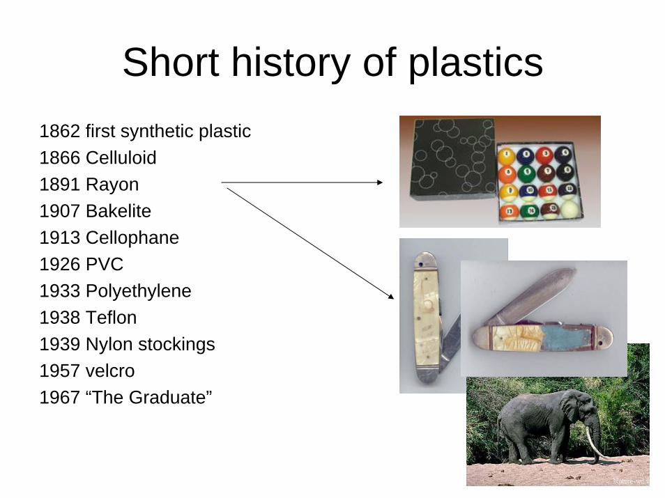
Short history of plastics1862 first synthetic plastic1866 Celluloid1891 Rayon1907 Bakelite1913 Cellophane1926 PVC1933 Polyethylene1938 Teflon1939 Nylon stockings1957 velcro1967 “The Graduate”

Outline
• Basic operation
• Cycle time and heat transfer
• Flow and solidification
• Part design
• Tooling
• New developments
• Environment

Readings
• Tadmore and Gogos
– Molding and Casting pp584 -610
• Boothroyd Dewhurst
– Design for Injection Molding pp 319 - 359
• Kalpakjian (5th ed) see Ch 19
• Injection molding case study;Washing machine
augers; see on web page
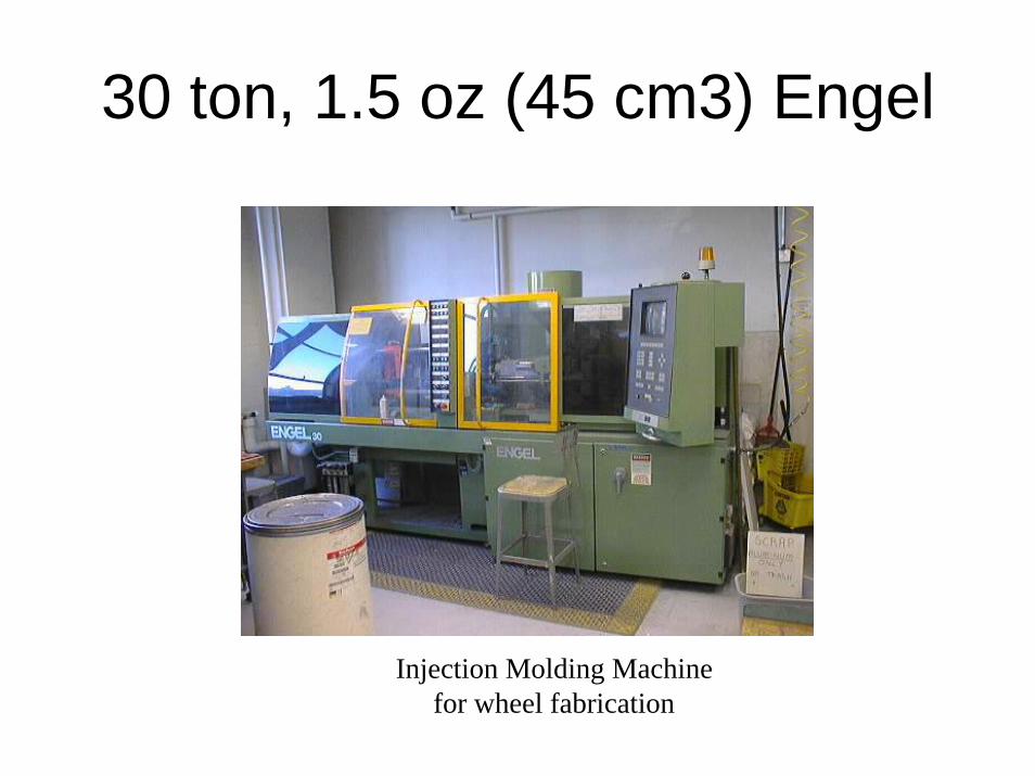
30 ton, 1.5 oz (45 cm3) Engel
Injection Molding Machinefor wheel fabrication
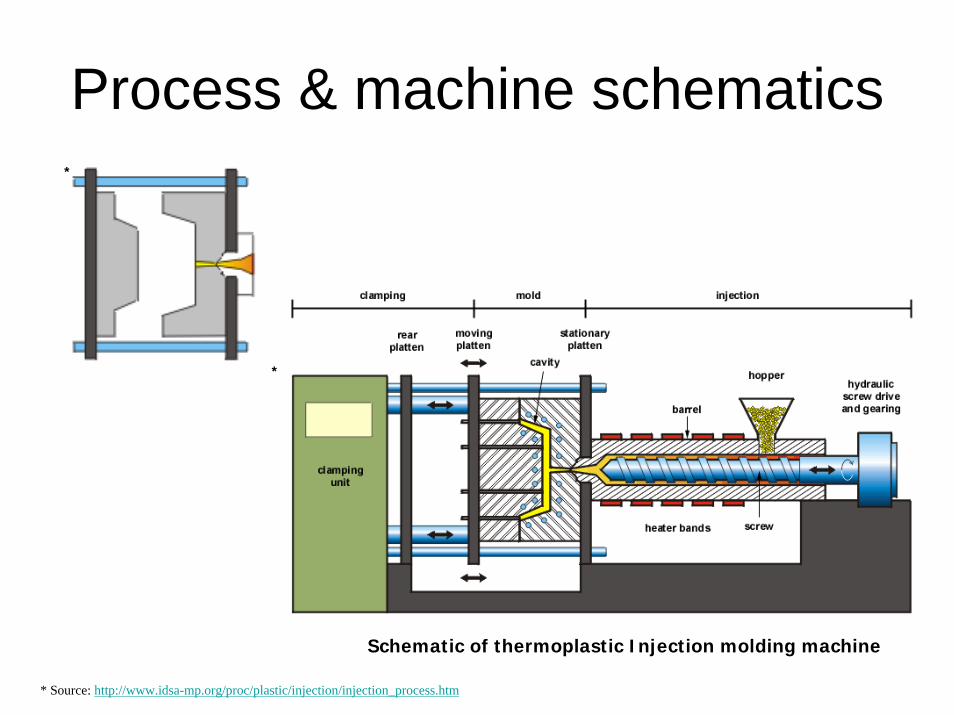
Process & machine schematics*
* Source: http://www.idsa-mp.org/proc/plastic/injection/injection_process.htm
*
Schematic of thermoplastic Injection molding machine
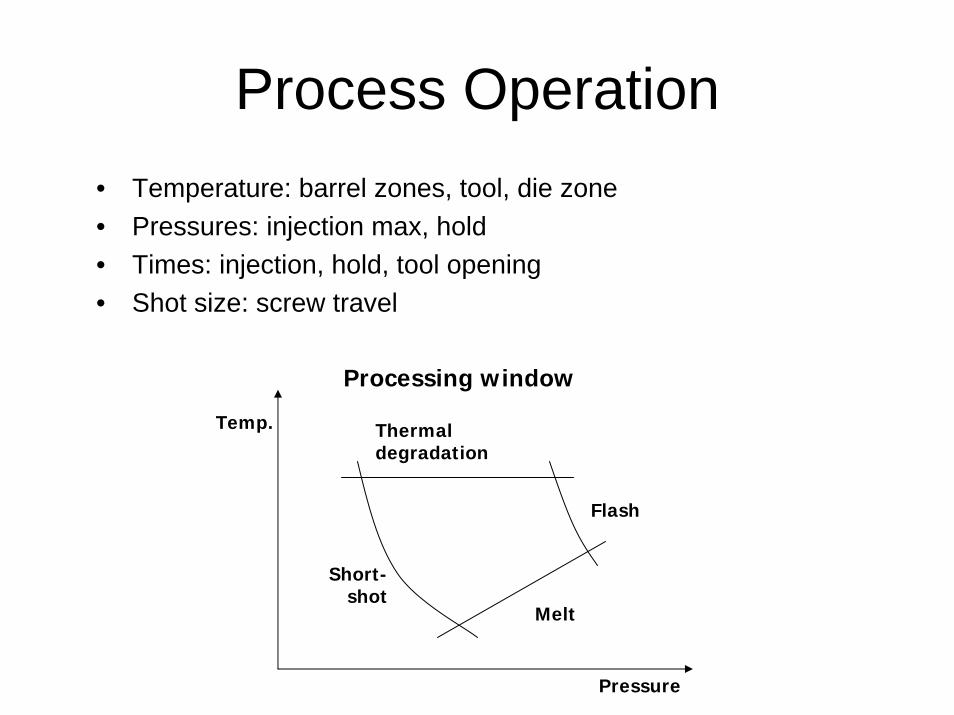
Process Operation• Temperature: barrel zones, tool, die zone• Pressures: injection max, hold• Times: injection, hold, tool opening• Shot size: screw travel
Flash
Melt
Thermaldegradation
Short-shot
Temp.
Pressure
Processing window
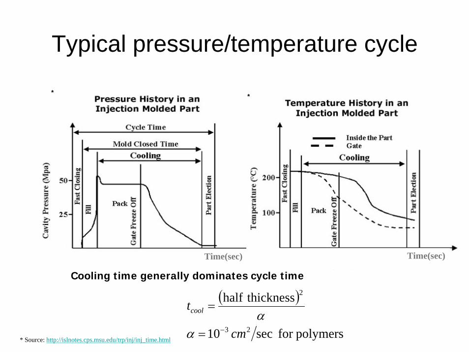
Typical pressure/temperature cycle
( )
polymersfor sec10
thicknesshalf
23
2
cm
tcool
−=
=
αα
Time(sec)
Cooling time generally dominates cycle time
Time(sec)
* Source: http://islnotes.cps.msu.edu/trp/inj/inj_time.html
* *
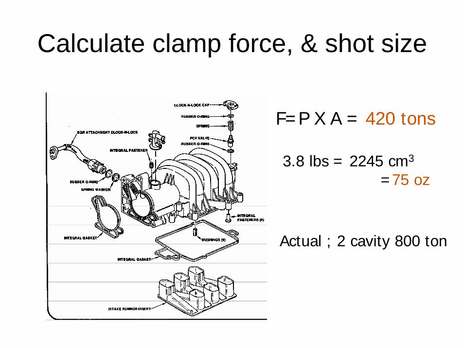
Calculate clamp force, & shot size
F=P X A = 420 tons
3.8 lbs = 2245 cm3
=75 oz
Actual ; 2 cavity 800 ton

Clamp force and machine cost
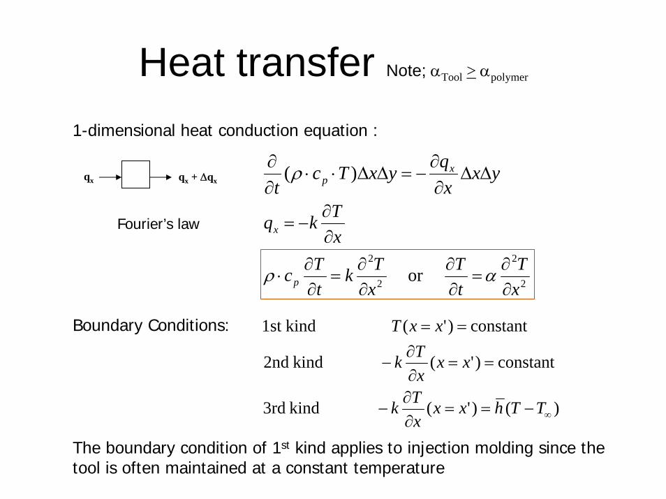
Heat transfer Note; αTool > αpolymer
yxxqyxTc
tx
p ΔΔ∂∂
−=ΔΔ⋅⋅∂∂ )(ρ
)()'( kind 3rd
constant)'( kind 2nd
constant)'( kind1st
∞−==∂∂
−
==∂∂
−
==
TThxxxTk
xxxTk
xxTBoundary Conditions:
1-dimensional heat conduction equation :
The boundary condition of 1st kind applies to injection molding since the tool is often maintained at a constant temperature
xTkqx ∂
∂−=
qx qx + Δqx
2
2
2
2
or xT
tT
xTk
tTcp ∂
∂=
∂∂
∂∂
=∂∂
⋅ αρ
Fourier’s law
Heat transfer
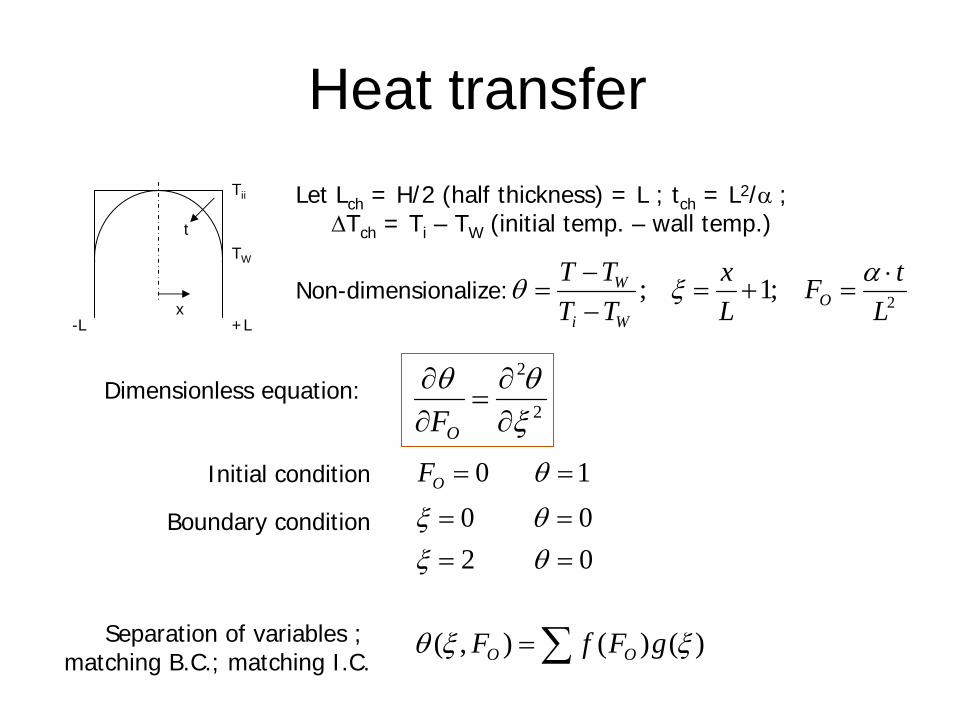
TW
Tii
t
x+L-L
Let Lch = H/2 (half thickness) = L ; tch = L2/α ;ΔTch = Ti – TW (initial temp. – wall temp.)
Non-dimensionalize: 2 ;1 ;L
tFLx
TTTT
OWi
W ⋅=+=
−−
=αξθ
2
2
ξθθ
∂∂
=∂∂
OFDimensionless equation:
Initial condition 1 0 == θOF
Boundary condition
0 20 0
====
θξθξ
Separation of variables ; matching B.C.; matching I.C. ∑= )()(),( ξξθ gFfF OO
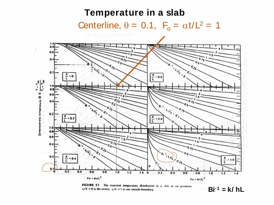
Centerline, θ = 0.1, Fo = αt/L2 = 1Temperature in a slab
Bi-1 =k/hL
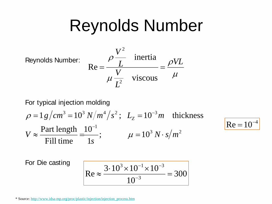
Reynolds Number
* Source: http://www.idsa-mp.org/proc/plastic/injection/injection_process.htm
μρ
μ
ρ VL
LVL
V
==s viscou
inertia Re
2
2
Reynolds Number:
For typical injection molding
231
32433
10 ;1
10 timeFilllengthPart
ess thickn10 ;101
msNs
V
mLsmNcmg Z
⋅==≈
===−
−
μ
ρ410Re −=
For Die casting
30010
1010103Re 3
313
=××⋅
≈ −
−−

Viscous Shearing of Fluidsv
F
h
hv
AF
∝
F/A
v/h
1
μ
Newtonian Viscosity
hvμτ =
Generalization: γμτ &=
)(γηγτ
&&
=
γ&
Injection molding
rateshear :γ&
Typical shear rate for Polymer processes (sec)-1
Extrusion 102~103
Calendering 10~102
Injection molding 103~104
Comp. Molding 1~10“Shear Thinning”
~ 1 sec-1 for PE
Viscous HeatingRate of Heating = Rate of Viscous Work
2
⎟⎠⎞
⎜⎝⎛=⋅=
⋅=
hv
hv
AF
VolvF
VolP μ
Rate of Temperature rise 22
or ⎟⎠⎞
⎜⎝⎛
⋅=⎟
⎠⎞
⎜⎝⎛=⋅
hv
cdtdT
hv
dtdTc
pp ρ
μμρ
Rate of Conduction out22
2
~hT
ck
dxTd
ck
dtdT
pp
Δ⋅⋅
=ρρ
Tkv
Δ=
2
Conductionheating Viscous μ
Brinkman number
For injection molding, order of magnitude ~ 0.1 to 10
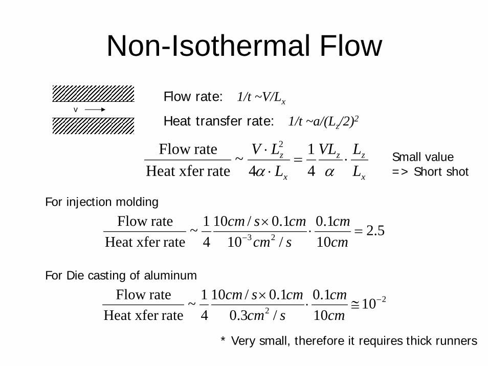
Non-Isothermal Flow
vFlow rate: 1/t ~V/Lx
Heat transfer rate: 1/t ~a/(Lz/2)2
x
zz
x
z
LLVL
LLV
⋅=⋅⋅
αα 41
4~
rateHeat xfer rate Flow 2
For injection molding
5.210
1.0/101.0/10
41~
rateHeat xfer rate Flow
23 =⋅×
− cmcm
scmcmscm
For Die casting of aluminum
22 10
101.0
/3.01.0/10
41~
rateHeat xfer rate Flow −≅⋅
×cmcm
scmcmscm
* Very small, therefore it requires thick runners
Small value=> Short shot
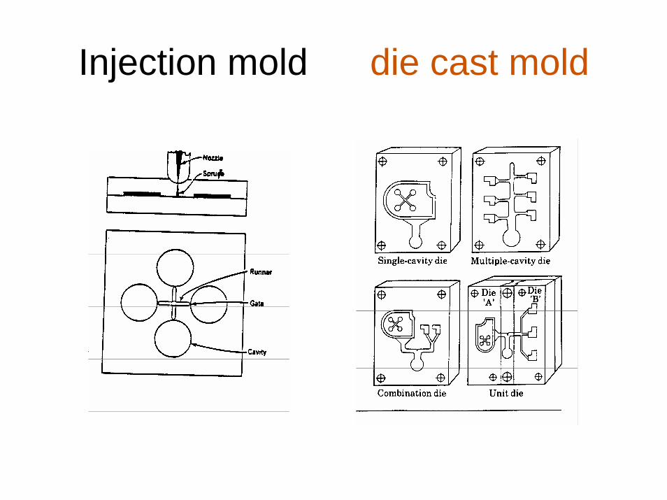
Injection mold die cast mold
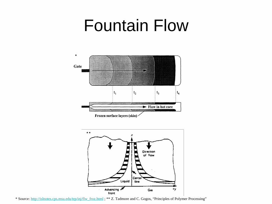
Fountain Flow
* Source: http://islnotes.cps.msu.edu/trp/inj/flw_froz.html ; ** Z. Tadmore and C. Gogos, “Principles of Polymer Processing”
*
**

Shrinkage distributions
* Source: G. Menges and W. Wubken, “Influence of processing conditions on Molecular Orientation in Injection Molds”
V=3.5cm/s
V=8cm/s
sample Transverse direction
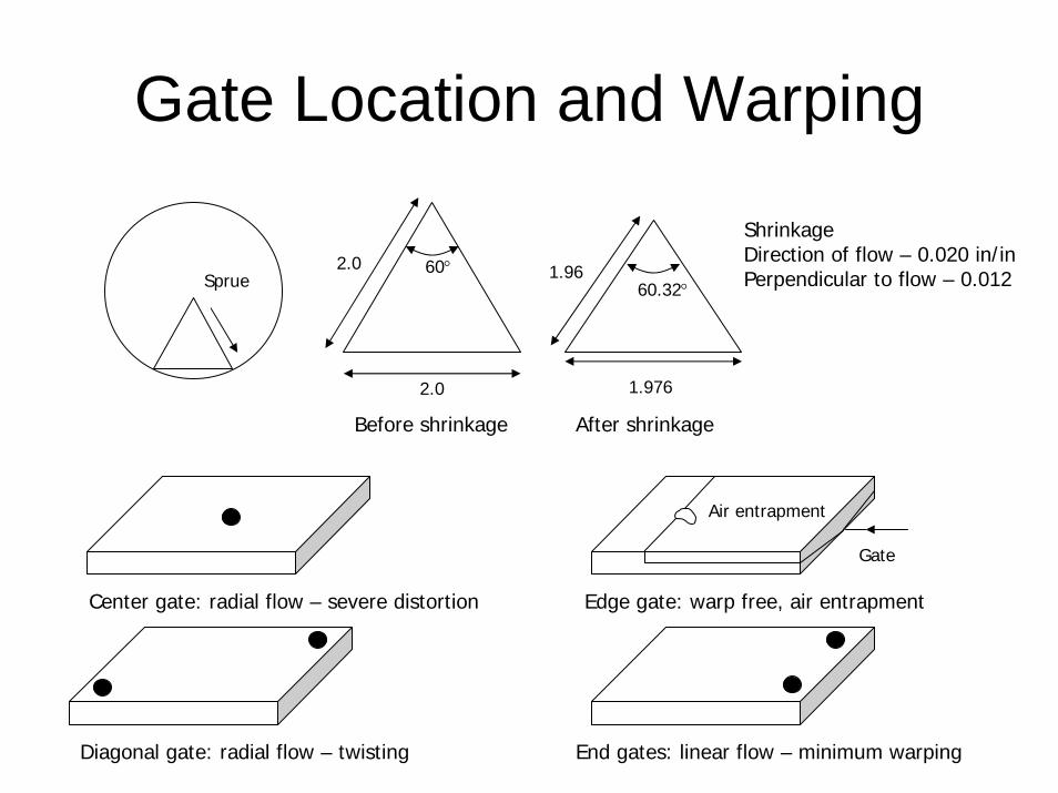
Gate Location and Warping
Center gate: radial flow – severe distortion
Diagonal gate: radial flow – twisting End gates: linear flow – minimum warping
Gate
Air entrapment
Edge gate: warp free, air entrapment
Sprue
2.0
2.0 60°
Before shrinkage
60.32°1.96
1.976
After shrinkage
ShrinkageDirection of flow – 0.020 in/inPerpendicular to flow – 0.012

Effects of mold temperature and pressure on shrinkage
0.030
0.000
0.010
0.005
0.015
0.020
0.025
100 120 140 160 180 200 220 240
Mold Temperature (F)
LDPE PP
Nylon 6/6
PMMA
Acetal
Shri
nka
ge
0.030
0.000
0.010
0.005
0.015
0.020
0.025
Shri
nka
ge6000
800010000
1200014000
16000
Pressure on injection plunger (psi)
AcetalLDPE
Nylon 6/6
PP with flow
18000
PP across flow
PMMA

Where would you gate this part?
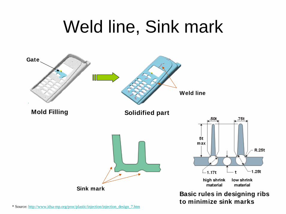
Weld line, Sink mark
* Source: http://www.idsa-mp.org/proc/plastic/injection/injection_design_7.htm
Weld line
Mold Filling
Gate
Solidified part
Sink markBasic rules in designing ribs to minimize sink marks
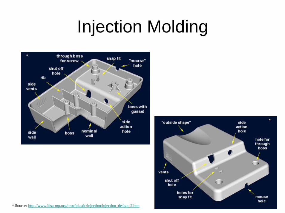
Injection Molding*
*
* Source: http://www.idsa-mp.org/proc/plastic/injection/injection_design_2.htm

Where is injection molding?

Effects of mold pressure on shrinkage
0.030
0.000
0.010
0.005
0.015
0.020
0.025
Shri
nka
ge
60008000
1000012000
1400016000
Pressure on injection plunger (psi)
AcetalLDPE
Nylon 6/6
PP with flow
18000
PP across flow
PMMA
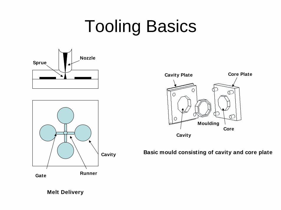
Tooling Basics
Cavity Plate
Cavity
MouldingCore
Core Plate
Basic mould consisting of cavity and core plate
Runner
Cavity
Gate
NozzleSprue
Melt Delivery

Part
Cavity
Core
Stripper plate
Tooling for a plastic cup
Runner
Knob
Nozzle
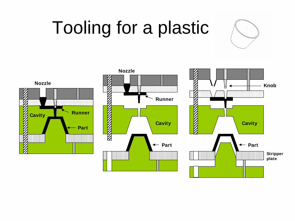
Tooling for a plastic cup
Runner
Part
Cavity
Nozzle
Part
Cavity
Knob
Stripper plate
Runner
Part
Cavity
Nozzle
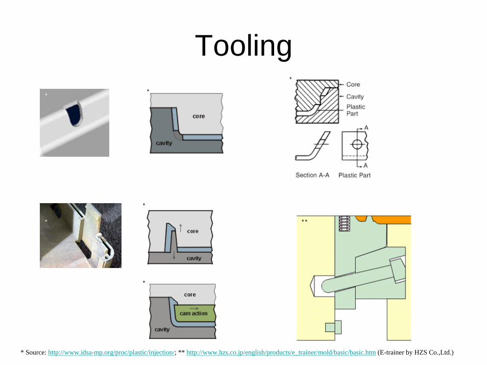
Tooling
* Source: http://www.idsa-mp.org/proc/plastic/injection/; ** http://www.hzs.co.jp/english/products/e_trainer/mold/basic/basic.htm (E-trainer by HZS Co.,Ltd.)
*
*
* **
**
*
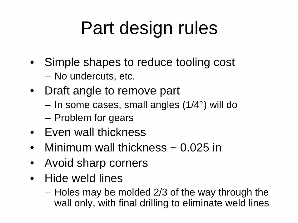
Part design rules
• Simple shapes to reduce tooling cost– No undercuts, etc.
• Draft angle to remove part– In some cases, small angles (1/4°) will do– Problem for gears
• Even wall thickness• Minimum wall thickness ~ 0.025 in• Avoid sharp corners• Hide weld lines
– Holes may be molded 2/3 of the way through the wall only, with final drilling to eliminate weld lines
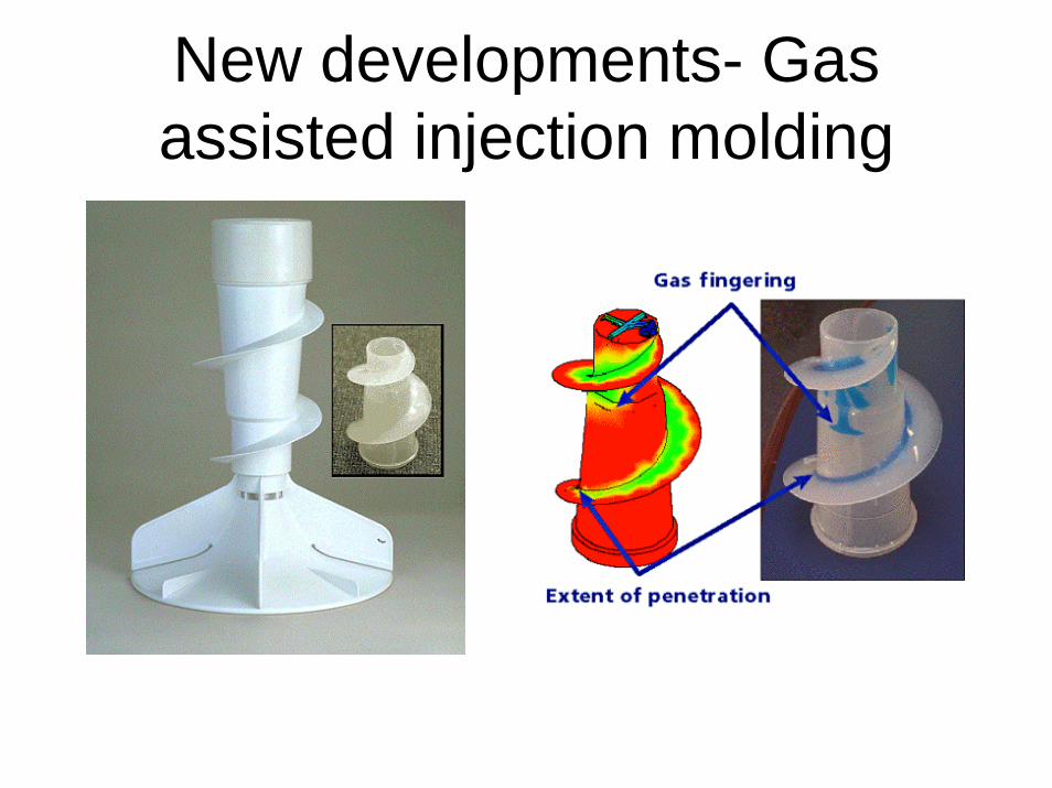
New developments- Gas assisted injection molding
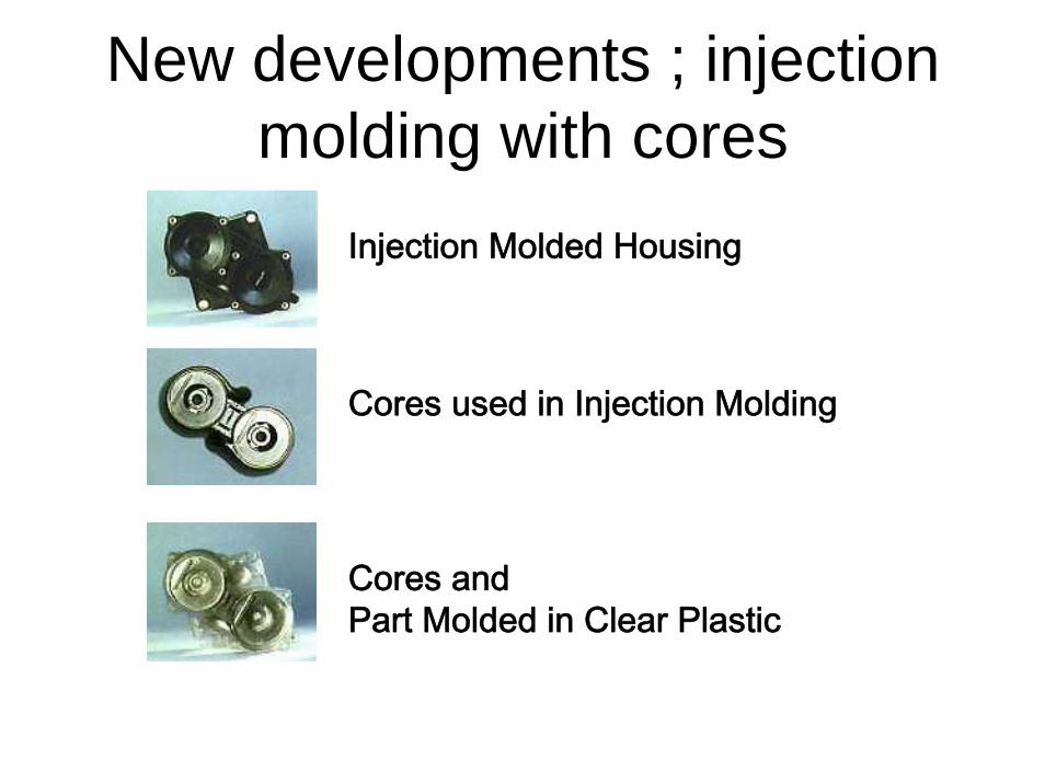
New developments ; injection molding with cores
Cores and Part Molded in Clear Plastic
Cores used in Injection Molding
Injection Molded Housing

Environmental issues
• System boundaries
• Polymer production
• Compounding
• Machine types
• Out gassing & energy during processing
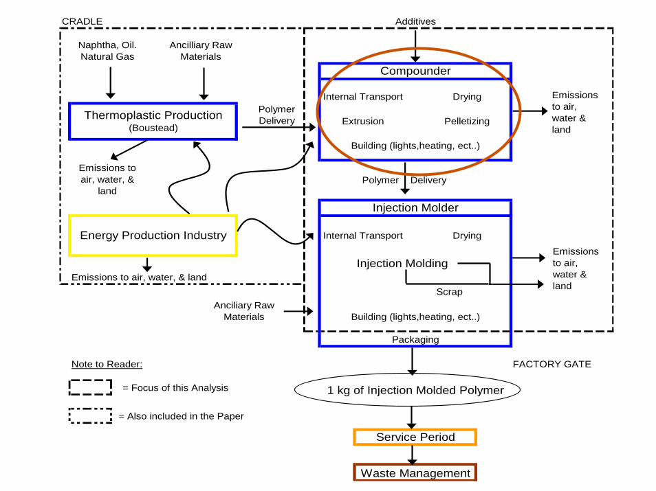
CRADLE
Polymer Delivery
Injection MoldingEmissions to air, water, & land
Scrap
Note to Reader: FACTORY GATE
= Also included in the Paper
Polymer Delivery
Naphtha, Oil. Natural Gas
Ancilliary Raw Materials
Thermoplastic Production (Boustead)
Internal Transport
Additives
Compounder
Pelletizing
Building (lights,heating, ect..)
Energy Production Industry
Anciliary Raw Materials
Emissions to air, water, &
land
Internal Transport Drying
= Focus of this Analysis
Waste Management
Drying
Building (lights,heating, ect..)
Packaging
Injection Molder
Extrusion
Service Period
1 kg of Injection Molded Polymer
Emissions to air, water & land
Emissions to air, water & land
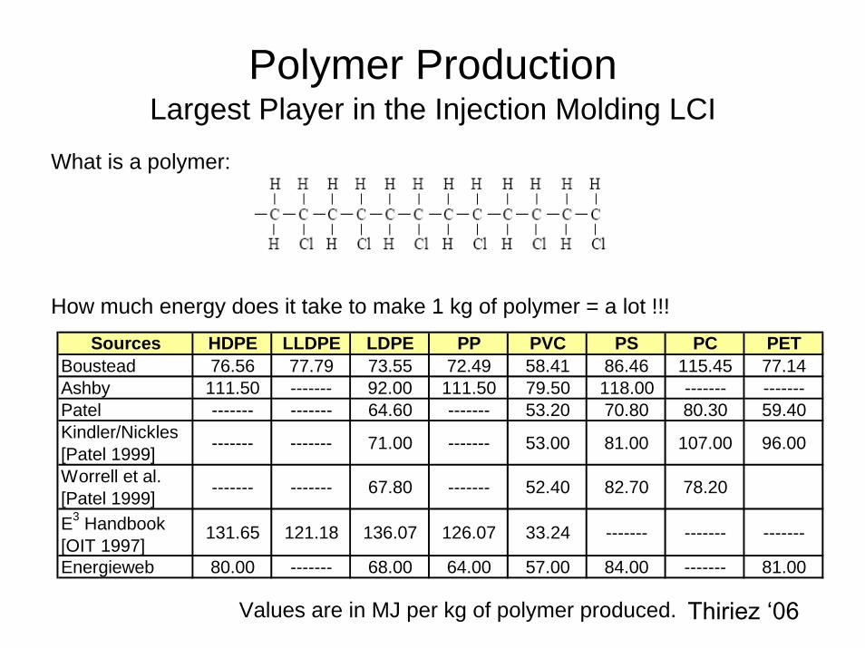
Polymer ProductionLargest Player in the Injection Molding LCI
Sources HDPE LLDPE LDPE PP PVC PS PC PETBoustead 76.56 77.79 73.55 72.49 58.41 86.46 115.45 77.14Ashby 111.50 ------- 92.00 111.50 79.50 118.00 ------- -------Patel ------- ------- 64.60 ------- 53.20 70.80 80.30 59.40Kindler/Nickles [Patel 1999] ------- ------- 71.00 ------- 53.00 81.00 107.00 96.00
Worrell et al. [Patel 1999] ------- ------- 67.80 ------- 52.40 82.70 78.20
E3 Handbook [OIT 1997]
131.65 121.18 136.07 126.07 33.24 ------- ------- -------
Energieweb 80.00 ------- 68.00 64.00 57.00 84.00 ------- 81.00
What is a polymer:
How much energy does it take to make 1 kg of polymer = a lot !!!
Values are in MJ per kg of polymer produced. Thiriez ‘06
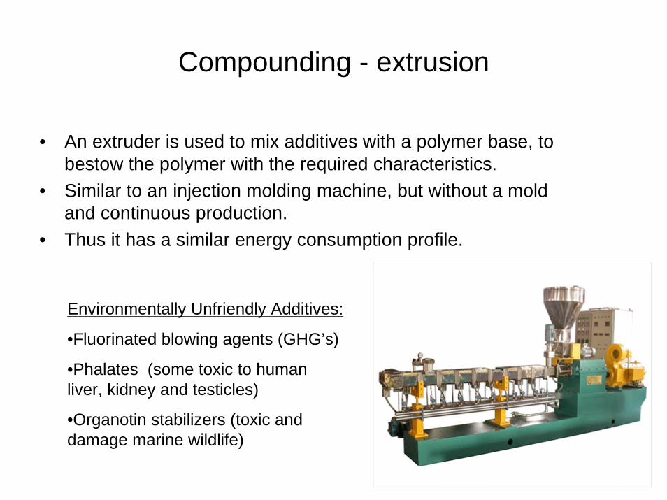
Compounding - extrusion
• An extruder is used to mix additives with a polymer base, to bestow the polymer with the required characteristics.
• Similar to an injection molding machine, but without a mold and continuous production.
• Thus it has a similar energy consumption profile.
Environmentally Unfriendly Additives:
•Fluorinated blowing agents (GHG’s)
•Phalates (some toxic to human liver, kidney and testicles)
•Organotin stabilizers (toxic and damage marine wildlife)
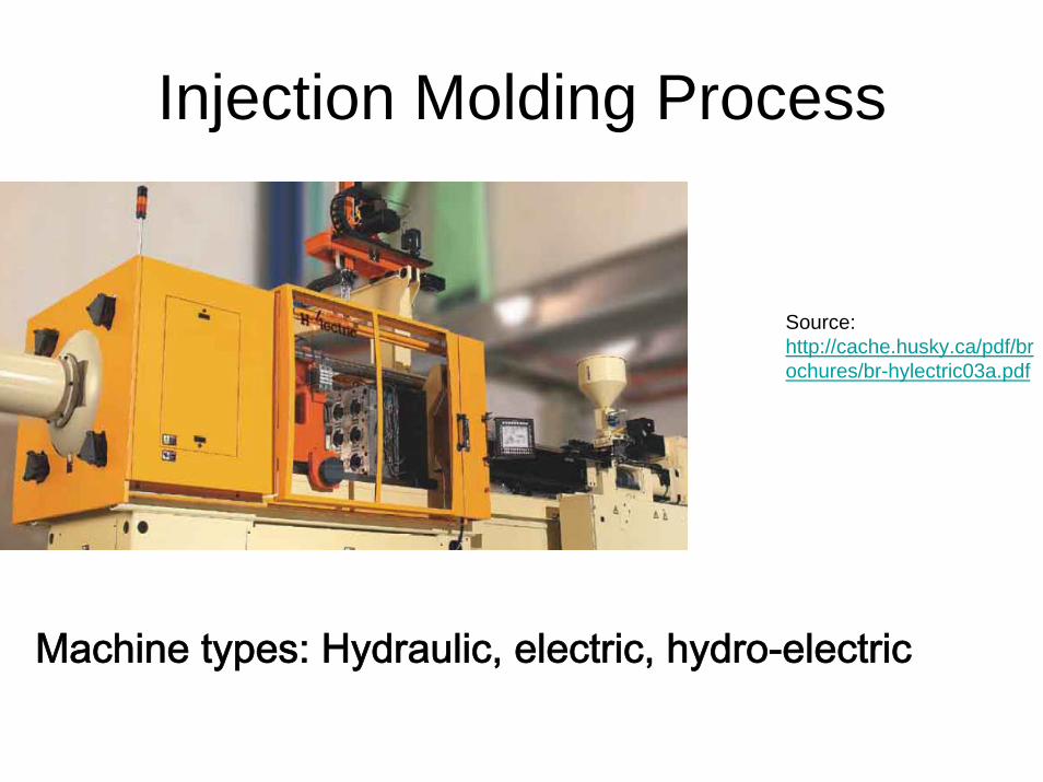
Injection Molding Process
Source: http://cache.husky.ca/pdf/brochures/br-hylectric03a.pdf
Machine types: Hydraulic, electric, hydro-electric
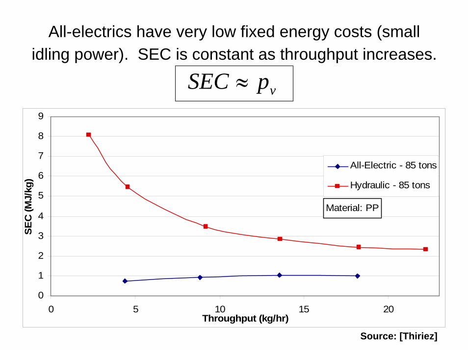
All-electrics have very low fixed energy costs (small idling power). SEC is constant as throughput increases.
vpSEC ≈
0
1
2
3
4
5
6
7
8
9
0 5 10 15 20Throughput (kg/hr)
All-Electric - 85 tons
Hydraulic - 85 tons
SEC
(MJ/
kg)
Material: PP
Source: [Thiriez]
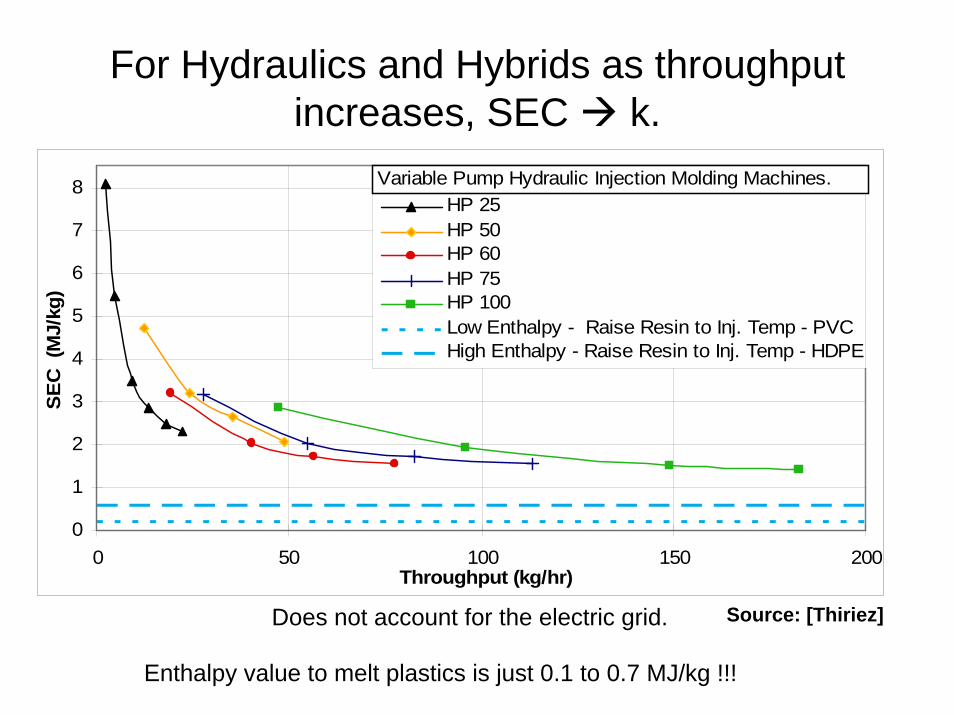
For Hydraulics and Hybrids as throughput increases, SEC k.
0
1
2
3
4
5
6
7
8
0 50 100 150 200Throughput (kg/hr)
SEC
(MJ/
kg)
HP 25HP 50HP 60HP 75HP 100Low Enthalpy - Raise Resin to Inj. Temp - PVCHigh Enthalpy - Raise Resin to Inj. Temp - HDPE
Variable Pump Hydraulic Injection Molding Machines.
Does not account for the electric grid. Source: [Thiriez]
Enthalpy value to melt plastics is just 0.1 to 0.7 MJ/kg !!!
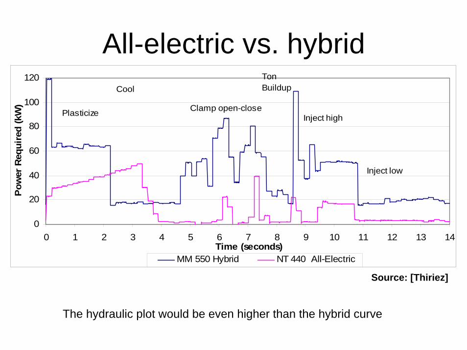
All-electric vs. hybrid
0
20
40
60
80
100
120
0 1 2 3 4 5 6 7 8 9 10 11 12 13 14Time (seconds)
Pow
er R
equi
red
(kW
)
MM 550 Hybrid NT 440 All-Electric
Plasticize Inject highClamp open-close
Inject low
t
CoolTon Buildup
Source: [Thiriez]
The hydraulic plot would be even higher than the hybrid curve
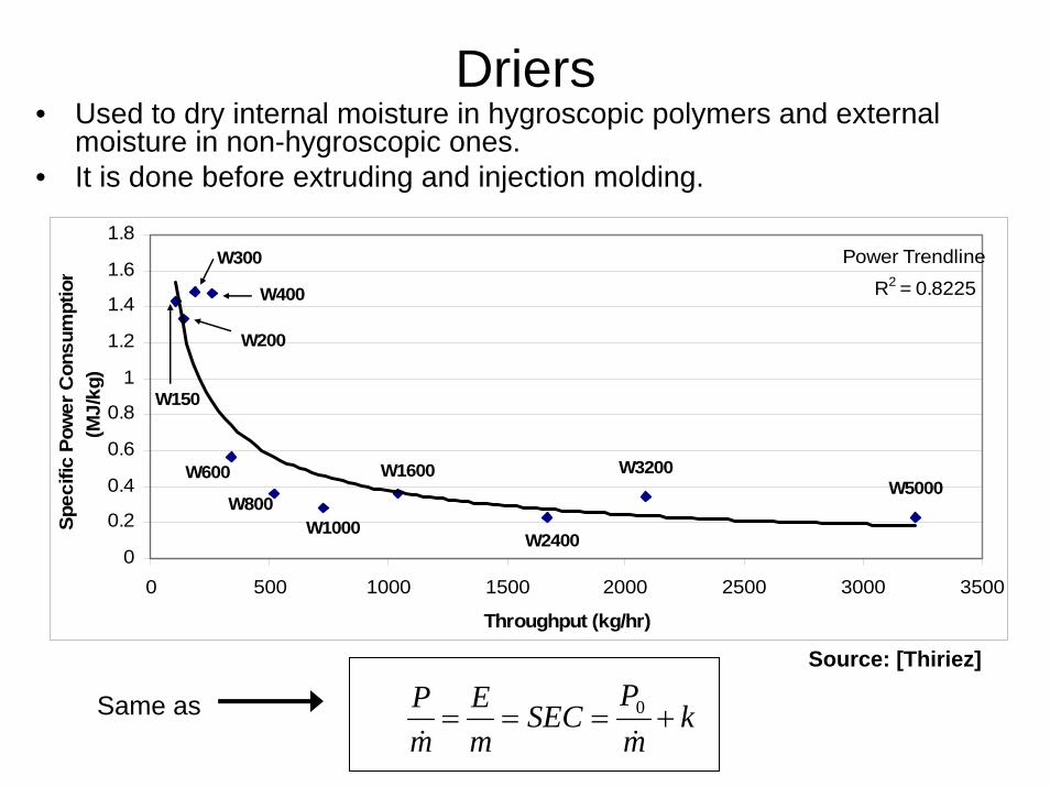
Driers• Used to dry internal moisture in hygroscopic polymers and external
moisture in non-hygroscopic ones. • It is done before extruding and injection molding.
W150
W200
W300
W400
W600
W800W1000
W1600
W2400
W3200W5000
R2 = 0.8225
0
0.2
0.4
0.6
0.8
1
1.2
1.4
1.6
1.8
0 500 1000 1500 2000 2500 3000 3500
Throughput (kg/hr)
Power Trendline
Spec
ific
Pow
er C
onsu
mpt
ion
(MJ/
kg)
kmP
SECmE
mP
+===&&0
Source: [Thiriez]
Same as
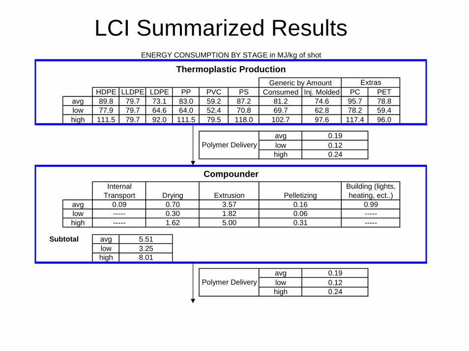
HDPE LLDPE LDPE PP PVC PS Consumed Inj. Molded PC PETavg 89.8 79.7 73.1 83.0 59.2 87.2 81.2 74.6 95.7 78.8low 77.9 79.7 64.6 64.0 52.4 70.8 69.7 62.8 78.2 59.4high 111.5 79.7 92.0 111.5 79.5 118.0 102.7 97.6 117.4 96.0
avglowhigh
avglowhigh
avglowhigh
avglowhigh
0.990.09-----
Thermoplastic ProductionGeneric by Amount Extras
Building (lights, heating, ect..)Pelletizing
Polymer Delivery0.19
Compounder
0.24
Internal Transport
0.190.120.24
Polymer Delivery
3.57
3.258.01
0.30 1.825.001.62
Extrusion0.70 0.16
-----0.06 -----0.31
Subtotal
0.12
-----
5.51
Drying
ENERGY CONSUMPTION BY STAGE in MJ/kg of shot
LCI Summarized Results
avglowhigh
avglowhigh
avglowhigh
avglowhigh
avglowhigh
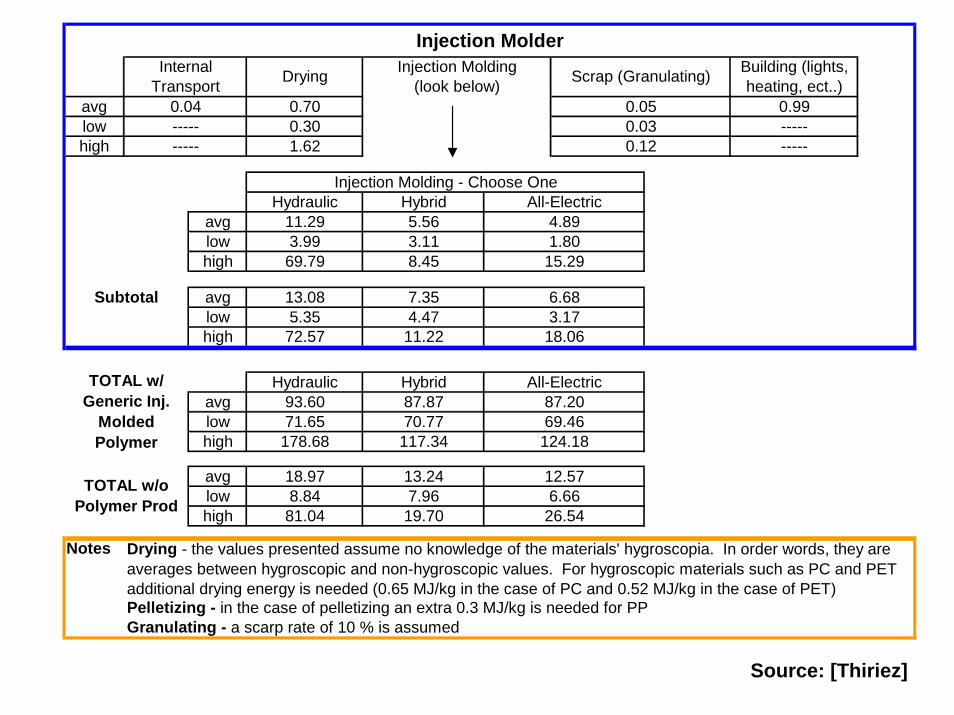
Notes Drying - the values presented assume no knowledge of the materials' hygroscopia. In order words, they are averages between hygroscopic and non-hygroscopic values. For hygroscopic materials such as PC and PET additional drying energy is needed (0.65 MJ/kg in the case of PC and 0.52 MJ/kg in the case of PET)
DryingInternal Transport
3.11 1.80
1.62-----0.30-----
Building (lights, heating, ect..)
0.99-----0.04 0.70
69.46117.34
7.35 6.68
124.18
87.87 87.2070.77
Hybrid All-Electric93.60
Subtotal
TOTAL w/ Generic Inj.
Molded Polymer
71.65178.68
Hydraulic
72.57
-----
13.085.35
11.293.9969.79
5.56 4.89Hydraulic Hybrid All-Electric
Injection Molding - Choose One
19.70 26.54
4.47 3.1711.22 18.06
8.45 15.29
Injection Molder
TOTAL w/o Polymer Prod
18.97
81.04
Granulating - a scarp rate of 10 % is assumedPelletizing - in the case of pelletizing an extra 0.3 MJ/kg is needed for PP
13.24 12.578.84 7.96 6.66
Injection Molding (look below) Scrap (Granulating)
0.050.030.12
Source: [Thiriez]

Energy Production Industry
The Grid is about 30% efficient
Hydro Nuclear Other Coal Oil GasWaste/
Renewable7.1% 19.6% 0.0% 50.7% 3.1% 16.7% 2.2%
United States Electricity Composition by Source
For every MJ of electricity we also get:
171.94 g of CO2
0.76 g of SO2
0.31 g of NOx
6.24 g of CH4
0.0032 mg of Hg
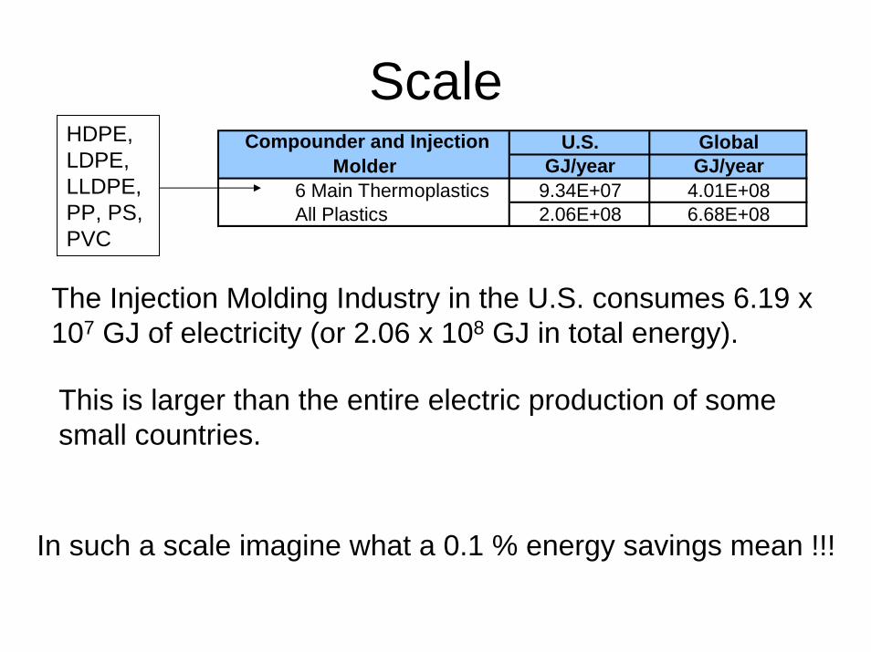
Scale
6 Main Thermoplastics
Compounder and Injection Molder
4.01E+082.06E+08 6.68E+08
U.S.GJ/year
9.34E+07
Global
All Plastics
GJ/yearHDPE, LDPE, LLDPE, PP, PS, PVC
The Injection Molding Industry in the U.S. consumes 6.19 x 10⁷ GJ of electricity (or 2.06 x 10⁸ GJ in total energy).
This is larger than the entire electric production of some small countries.
In such a scale imagine what a 0.1 % energy savings mean !!!
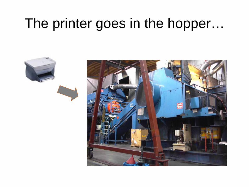
The printer goes in the hopper…
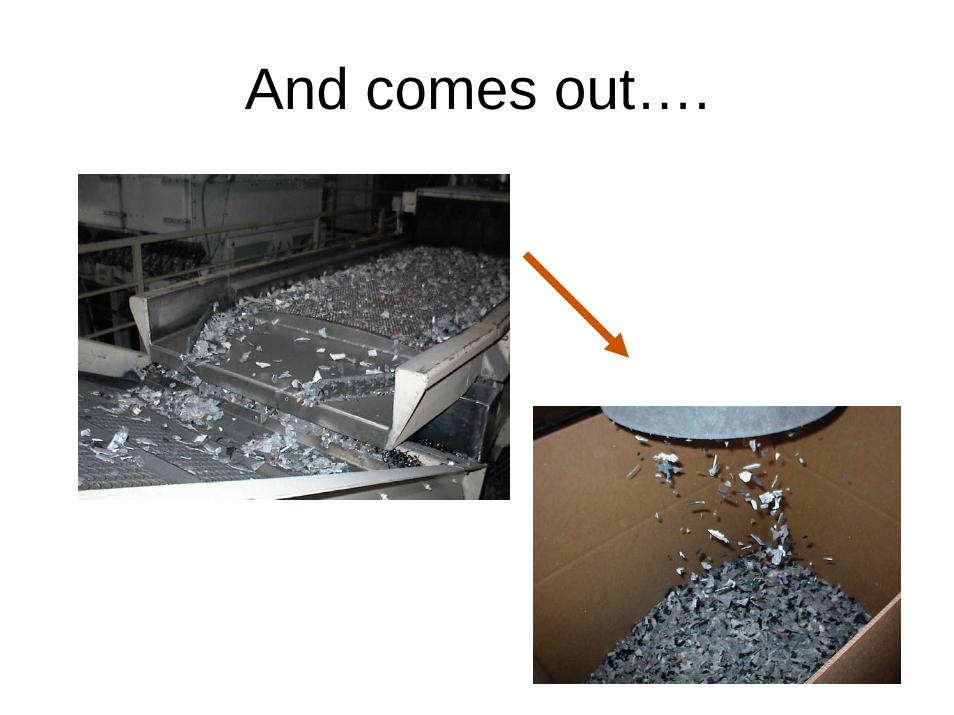
And comes out….
Readings
1. Z. Tadmore et al., "Molding and Casting" p. 584 - 610
2. G. Boothroyd et al., "Design for Injection Molding“p.319 - 360
3. S. Shingo, "Single Minute Exchange of Dies“
4. Thiriez et al, "An Environmental Analysis of Injection Molding“
5. "Injection Molding Case Study“
6. Kalpakjian Chapter 19 (Chapter 18)