influence of convection-dependent adsorption of …...influence of convection-dependent adsorption...
TRANSCRIPT

Journal of The Electrochemical Society,152 ~6! C425-C434~2005! C425
Influence of Convection-Dependent Adsorption of Additives onMicrovia Filling by Copper ElectroplatingWei-Ping Dow,* ,z Her-Shu Huang,a Ming-Yao Yen, and Hsiao-Chun Huang
Department of Chemical Engineering, National Yunlin University of Science and Technology, Touliu,Yunlin 640, Taiwan
Influences of forced convection during acid copper electroplating on microvia fill of printed circuit boards were studied. Theplating formula was composed of polyethylene glycol~PEG!, chloride ion, 3-mercapto-1-propanesulfonate, and Janus green B~JGB!. The filling performances under various plating conditions were examined with scanning electron microscopy and opticalmicroscopy. Chemical and physical interactions between these additives and fluid dynamics were characterized by cyclic linearsweep voltammetry, steady-state current-potential measurements, linear sweep voltammetry, and galvanostatic measurementsusing different rotation speeds of working electrode. Experimental results indicated that the potential-dependent adsorption ofchloride ion on the copper surface determined and governed the electrochemical effect of these organic additives on the cathode,resulting in a convection-dependent adsorption of inhibiting reagents and an asymmetrical fill of copper deposit in the microvias.A synergistic inhibition effect on the copper deposition caused by a composite suppressor composed of PEG, Cu+, Cl−, and JGBwas demonstrated. The dominance of the competitive adsorption between the accelerator and the composite suppressor was shownto depend significantly on the chloride ion concentration and on the forced convection.© 2005 The Electrochemical Society.@DOI: 10.1149/1.1901670# All rights reserved.
Manuscript submitted October 20, 2004; revised manuscript received December 20, 2004. Available electronically May 12, 2005.
0013-4651/2005/152~6!/C425/10/$7.00 © The Electrochemical Society, Inc.
tion
ationucts.the-rfill
sitione viathefet-
ed in
eratingrp-ules
ini-om-non
ion,orviaswasise,
-uctiotheadd
died.dslev
larly,pos
lorideelec-elersle
f cop-ocallytheddi-
ngg is
is ex-the
f cop-, ornvec-ion
ectro-aviorsthistween
om-fillingandhere-ionnt ofrfacelari-wasctioninant
nvec-devi-
timesob-eri-give
tion.
withre.
ircuit
Via metallization by copper electrodeposition for interconnecof integrated circuit~IC! chips and of printed circuit boards~PCBs!has become increasingly important because of the miniaturizand multifunctional designs of state-of-the-art electronic prodIn this metallization technique, copper was directly filled intovias by electroplating using specific plating additives.1-4 These additives functioned synergistically to cause bottom-up fill or supeof copper deposits in the vias in which the copper electrodeporate at the bottom of the via is dramatically greater than at thopening. This interesting filling behavior not only occurred insubmicrometer vias of wafers,1-3 but also in the microvias oPCBs.5-10 In practice, the plating additives used for the copper mallization in IC chip fabrication were the same as those employPCB fabrication.
According to previous reports,2-4,10,11the plating additives werdivided into two categories, namely, suppressing and accelereagents. Functionally, both polyethylene glycol~PEG! and levele~i.e., Janus Green B! ~JGB! belong to inhibiting reagents that supress the copper deposition rate, while thiol and disulfide molecsuch as 3-mercapto-1-propanesulfonate~MPS! and bis~3-sulfopropyl! disulfide ~SPS!, enhance the copper deposition ratethe presence of chloride ion.11 It is commonly known that the inhbition effect of PEG on copper electrodeposition results from a cplex film composed of PEG, Cu+, and Cl− and strongly adsorbed othe copper surface.12-14 The acceleration effect of MPS or SPSCu2+ reduction is caused by their interaction with chloridenamely, a chemically synergistic effect.8,11 When both suppressand accelerator were present in the electrolyte, superfill of thecould be conditionally achieved. The accelerator concentrationcertainly very low when the electrolyte lacked a leveler. Otherwconformal deposition was obtained.8,9 The formula with lower accelerator concentration was not easily used for the mass prodof microvia fill because of the narrow operation window ofaccelerator concentration. Hence, leveler was an indispensabletive for industrial applications.
The electrochemical behavior of the leveler was rarely stuAccording to the literature,1-4,15 amine and heterocyclic compounare common functional groups of these levelers. Usually, theseelers bear primary, secondary, or tertiary amines, or particuquaternary ammonium salt. Therefore, these levelers commonly
* Electrochemical Society Active Member.a Present address: Research and Development Department, Gold C
Electronics, Limited, Chung-Li Industrial Part, Taoyuan, Taiwan.z E-mail: [email protected]
,
n
i-
-
-
sess one or more positive charges. Naturally, one or more chions are the concomitants in order to maintain the moleculartroneutrality. Figure 1 shows typical molecule structures for levsuch as JGB and Diazine Black~DB!. These ammoniums enabthese levelers to be adsorbed preferentially on the protrusion oper deposits due to the electrostatic attraction caused by the lhigh electron density.16 Therefore, the plated throwing power ofthrough hole in the PCB can be significantly improved by the ation of a leveler in plating solution. For microvia fill, a levelieffect, in which the rate of copper deposition at the via openinreduced and that at the bottom of the microvia is enhanced,pected to occur. Additionally, the rate of copper deposition onboard surface is also expected to be reduced relative to that oper deposition at the bottom of the microvia. Unlike PEG, MPSSPS, levelers are not good wetting agents; therefore, forced cotion is an important factor for reducing the thickness of diffusboundary layer of the leveler.6,15,17
In this work, a typical leveler~i.e., JGB! was chosen as thmodel additive. An attempt was made to elucidate the JGBs elechemical and adsorptive behaviors and to correlate these behwith the filling performance of the plating formula. Besides,work demonstrated that there was a synergistic interaction bethe suppressor~i.e., PEG! and the leveler~i.e., JGB!, which signifi-cantly redoubled the inhibition effect on copper deposition cpared to that of individual reagents, and thus redounded to theperformance. This synergistic inhibition effect between PEGJGB was demonstrated to be related with forced convection. Tfore, the improvement of filling performance following the additof the leveler could be reasonably explained if the impingemeforced convection acting at the via opening and the board suwas much stronger than at the via bottom. This work further cfied the mechanism of microvia fill, in which the acceleratorpredominant at the bottom of the microvia due to weak conveand the suppressor and the leveler were synergistically predomat the via opening and at the board surface owing to strong cotion. Once the synergy between suppression and accelerationated from balance, conformal deposition was obtained. Somean oblique copper plane at the top of the filled microvia wastained due to the unidirectional flow of the plating solution. Expmental results indicated that PEG and JGB could interact andrise to a synergistic inhibition effect on copper electrodeposiThis synergy of PEG and JGB was convection-dependent.
Experimental
The preparations and pretreatments of the PCB fragmentsvarious via diameters have been described in detail elsewhe8,10

d ininu-
asst theowstinuatinu-one
oardillus-
ests
-ting
llingcan-
al
ere
0 m
rode. A
ceing
tionulatem towas
ure-e Pt
forefrom
n thet in a
-so-ea-e wasuced.viorsined,be-
orp-tial-were
s. Thesed of
-ationcon-dem-
eepingLSVhose of
addi-nden-
tionotion
tively.the
proce-
llppmased
00ined.is aaviarwise,
f the
able
PEGas ofectro-EG,cor-o thensthe
ctionithinpar-perarge
C426 Journal of The Electrochemical Society, 152 ~6! C425-C434~2005!C426
The procedures of the filling plating have also been reporteprevious works.8,10 Constant agitation was performed by a contous flow of air bubbles during electroplating to ensure good mtransfer. The rectangular PCB fragment was placed vertically acenter of the plating bath. Small rising air bubbles formed two rfrom the downside of the PCB fragment and thus created a contangential fluid flow along the PCB fragment’s surface. The conous fluid motion on the board surface almost always flowed indirection. Therefore, the direction of the stream line on the bsurface was fixed during electroplating. The plating bath wastrated in detail elsewhere.10
The composition of standard electrolyte used in all filling twas 0.88 M CuSO4·5H2O ~Riedel-de Haën, ACS! and 0.54 MH2SO4 ~Merk, 96%, Ultrapure!. The additives, MPS~Aldrich!, JGB~Aldrich!, and PEG with a molecular weight of 8000~Fluka!, andchloride ion ~i.e., NaCl! ~Fisher, Certified ACS!, were added concomitantly to the plating solution. The temperature of the plasolution during electroplating was maintained at 25°C. The fiperformance of different plating formulas was examined with sning electron microscopy~SEM, Hitachi S-3500N! for a top view ofthe microvia and with optical microscopy~OM! for a cross-sectionview of the microvia.
The electrochemical and inhibitive behaviors of the leveler wcharacterized with cyclic linear sweep voltammetry~CLSV! usingdifferent rotation speeds of the working electrode~WE!. All CLSVmeasurements were performed in a glass vessel containing 10of electrolyte solution and using a PGSTAT30~AUTO-LAB ! poten-tiostat with a three-electrode cell. A platinum rotating disk elect~Pt-RDE! with a diameter of 3 mm was employed as the WEsmall platinum foil was chosen as a counter electrode~CE! and asaturated mercurous sulfate electrode~SSE! served as a referenelectrode~RE!. The CLSV was carried out by a negative-gosweep from open circuit potential~OCP! to −0.9 V vs. SSE, fol-lowed by a positive-going sweep from −0.9 Vvs.SSE to OCP.
To simulate the fluid motion around the PCB, two rotaspeeds of WE were chosen. One was fixed at 150 rpm to simthe fluid motion at the via bottom. The other was set at 2500 rpsimulate the fluid motion at the board surface. The scan rate1 mV/s for all CLSV measurements. Before each CLSV measment, a thin copper layer of 500 nm was predeposited onto thRDE in a predeposition bath, containing only 0.06 M CuSO4·5H2O~Riedel-de Haën, ACS! and 0.9 M HSO ~Merk, 96%, Ultrapure!.
Figure 1. Molecular structures of typical levelers:~A! Janus Green B~JGB!,and ~B! Diazine black~DB!.
2 4
l
L
-
The test electrolyte was first purged with nitrogen for 1 h beCLSV measurement in order to remove the dissolved oxygenthe solution.
To emphasize the effects and interactions of the additives ocopper electrodeposition, CLSV measurements were carried oubase electrolyte composed of 0.06 M CuSO4·5H2O and 0.9 MH2SO4. Low cupric ion concentration and high H2SO4 concentration ~i.e., supporting electrolyte! could markedly enhance the relution and sensitivity of current density variation in the CLSV msurements, because the resistance of the base electrolytdecreased and the migration current of cupric ion was redBased on this analysis condition, significant polarization behaof these additives relative to an additive-free solution were obtawhich was greatly helpful in explaining the causal relationshipstween the chemical interaction and the fluid dynamics.
The influence of the chloride ion concentration on PEG adstion at different forced convection levels and the potendependent adsorption of chloride ions on the copper surfacecharacterized by steady-state current-potential measurementbase electrolyte prepared for the measurement was compo0.88 M CuSO4·5H2O and 0.54 M H2SO4, which was the same composition as that used for practical plating. The PEG concentrwas fixed at 200 ppm for all measurements. Two chloride ioncentrations, 10 and 90 ppm, were chosen for comparison. Toonstrate that the suppression effect of the inhibitor~i.e., PEG +JGB! was sensitive to the chloride ion concentration, a linear swvoltammetry ~LSV! was carried out by using a practical platsolution. The rotation speed of the WE was 400 rpm during themeasurement. The scan rate and range were the same as tCLSV.
To further explore the competitive adsorption among thesetives, several galvanostatic measurements~GMs! were carried out ipractical plating solutions with various formulas. The currentsity adopted in the GMs was 18 A/ft2 ~ASF, >19.4 mA/cm2! whichwas the same as the filling plating condition. Also, two rotaspeeds, 150 and 2500 rpm, were chosen to simulate the fluid mat the bottom of the microvia and at the board surface, respecThe total time for each GM was 70 min, which was equal topractical plating time. The measurements, pretreatments, anddures were described in detail elsewhere.11
Results
Filling plating.—A previous work10 has shown that superfiwas obtained from a plating formula with 200 ppm PEG, 90Cl−, and 0.3 ppm MPS. When the MPS concentration was increto 3 ppm, and the PEG and Cl− concentrations were still fixed at 2and 90 ppm, respectively, conformal deposition was obtaTherefore, if accumulation of the accelerator in the microviacrucial factor for the performance of superfill,18,19 a premise thatstrong inhibition effect has to simultaneously function at theopening and at the board surface must be established. Othecathodic current does not preferentially work at the bottom omicrovia.
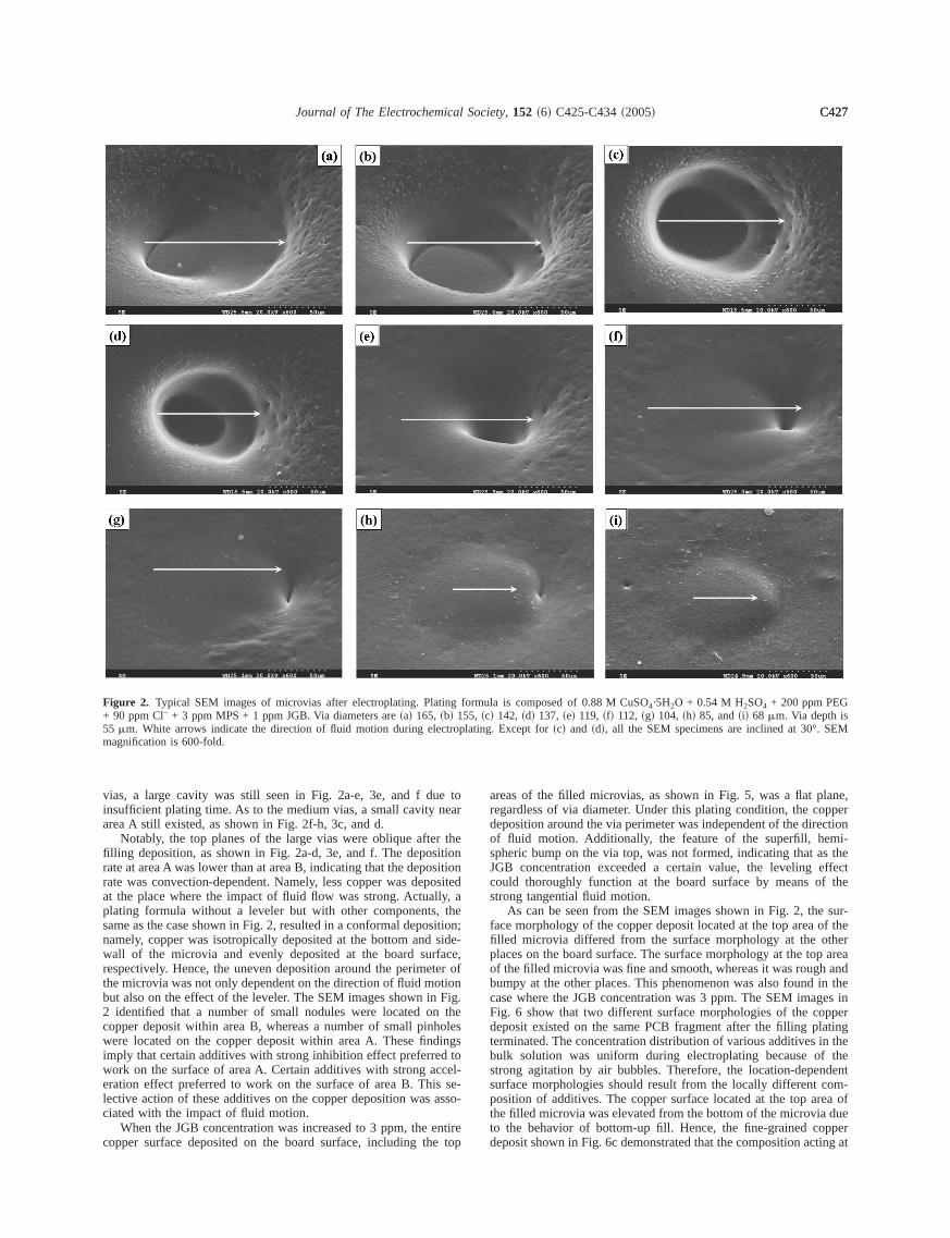
Interestingly, the conformal deposition caused by the unworkplating formula~i.e., 200 ppm PEG + 90 ppm Cl− + 3 ppm MPS!could be turned into a superfill after JGB was used along withand MPS. Figure 2 shows the SEM images of several microvivarious diameters formed on the same PCB fragment after elplating was performed in a plating solution with 200 ppm P90 ppm Cl−, 3 ppm MPS, and 1 ppm JGB. Figure 3 shows theresponding cross-sectional views of the microvias. According tdirection of fluid motion, Fig. 4 illustrates two specific locationear the microvia opening, namely, A and B. The direction ofsurface defined within area A is essentially opposite to the direof fluid motion, whereas the direction of the surface defined warea B is essentially parallel to the direction of fluid motion. Apently, the small vias, as shown in Fig. 2i, were fully filled by copdeposit and exhibited superfilling behavior, while as to the l
e toear
r theitionsitionosite
ly, athe
sitionsideface,ter otionFig.the
holesings
d toccel-s se-asso
entiree top
lane,pperctioni-
s theeffectf the
sur-of thetherp area
andin thees in
pperatingn the
thendentom-ea ofdueppering at
EM
C427Journal of The Electrochemical Society, 152 ~6! C425-C434~2005! C427
vias, a large cavity was still seen in Fig. 2a-e, 3e, and f duinsufficient plating time. As to the medium vias, a small cavity narea A still existed, as shown in Fig. 2f-h, 3c, and d.
Notably, the top planes of the large vias were oblique aftefilling deposition, as shown in Fig. 2a-d, 3e, and f. The deposrate at area A was lower than at area B, indicating that the deporate was convection-dependent. Namely, less copper was depat the place where the impact of fluid flow was strong. Actualplating formula without a leveler but with other components,same as the case shown in Fig. 2, resulted in a conformal deponamely, copper was isotropically deposited at the bottom andwall of the microvia and evenly deposited at the board surrespectively. Hence, the uneven deposition around the perimethe microvia was not only dependent on the direction of fluid mobut also on the effect of the leveler. The SEM images shown in2 identified that a number of small nodules were located oncopper deposit within area B, whereas a number of small pinwere located on the copper deposit within area A. These findimply that certain additives with strong inhibition effect preferrework on the surface of area A. Certain additives with strong aeration effect preferred to work on the surface of area B. Thilective action of these additives on the copper deposition wasciated with the impact of fluid motion.
When the JGB concentration was increased to 3 ppm, thecopper surface deposited on the board surface, including th
Figure 2. Typical SEM images of microvias after electroplating. Plati+ 90 ppm Cl− + 3 ppm MPS + 1 ppm JGB. Via diameters are~a! 165, ~b! 155 mm. White arrows indicate the direction of fluid motion during elecmagnification is 600-fold.
d
;-
f
-
areas of the filled microvias, as shown in Fig. 5, was a flat pregardless of via diameter. Under this plating condition, the codeposition around the via perimeter was independent of the direof fluid motion. Additionally, the feature of the superfill, hemspheric bump on the via top, was not formed, indicating that aJGB concentration exceeded a certain value, the levelingcould thoroughly function at the board surface by means ostrong tangential fluid motion.
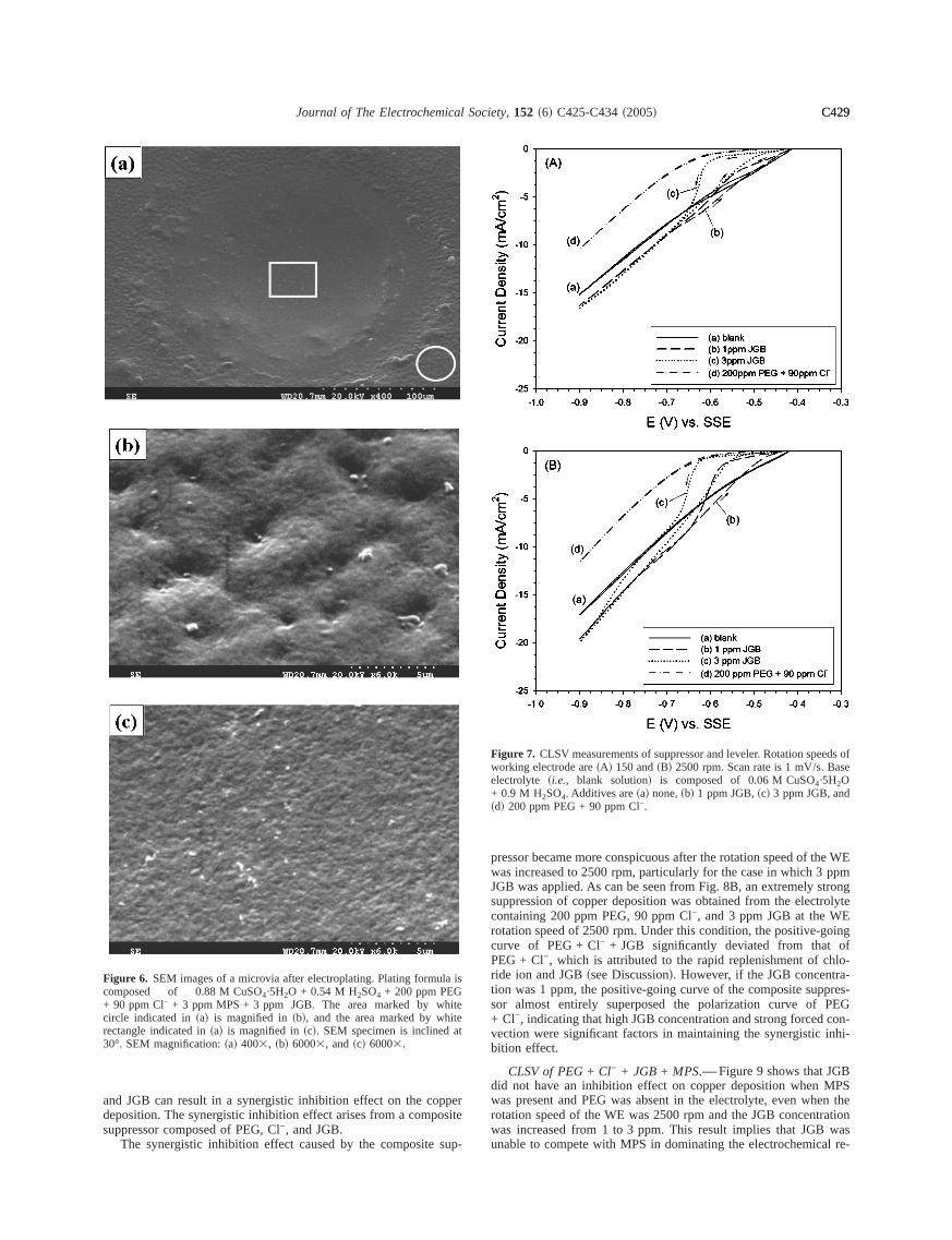
As can be seen from the SEM images shown in Fig. 2, theface morphology of the copper deposit located at the top areafilled microvia differed from the surface morphology at the oplaces on the board surface. The surface morphology at the toof the filled microvia was fine and smooth, whereas it was roughbumpy at the other places. This phenomenon was also foundcase where the JGB concentration was 3 ppm. The SEM imagFig. 6 show that two different surface morphologies of the codeposit existed on the same PCB fragment after the filling plterminated. The concentration distribution of various additives ibulk solution was uniform during electroplating because ofstrong agitation by air bubbles. Therefore, the location-depesurface morphologies should result from the locally different cposition of additives. The copper surface located at the top arthe filled microvia was elevated from the bottom of the microviato the behavior of bottom-up fill. Hence, the fine-grained codeposit shown in Fig. 6c demonstrated that the composition act
rmula is composed of 0.88 M CuSO4·5H2O + 0.54 M H2SO4 + 200 ppm PEG! 142, ~d! 137, ~e! 119, ~f! 112, ~g! 104, ~h! 85, and~i! 68 mm. Via depth isting. Except for~c! and ~d!, all the SEM specimens are inclined at 30°. S
ng fo55, ~ctropla

thef the- anwerce ofThisrh isar-
ent
ss-eed of
ffectpliedthanin-the
B atorideanfor
and
hownkerd
wasLSVen-
ction
effecti-edly
s-itive-EG-Cl
ing
ia
ca-
ing
ia
ca-
C428 Journal of The Electrochemical Society, 152 ~6! C425-C434~2005!C428
the bottom of the microvia was different from that acting onboard surface during electroplating; that is, the composition oadditives adsorbed on the copper surface were convectionlocation-dependent. In the microvia, the fluid velocity is slocompared with the outside bulk velocity, such that the shear forthe fluid acting on the copper surface at the via bottom is weak.scenario is beneficial to the action of the accelerator.11 The sheaforce of the fluid strongly impacts on the board surface, whicbeneficial to the action of the suppressor.11 These behaviors are chacterized by the following CLSV and GMs and are in agreemwith the previous work.11
Figure 3. Typical OM pictures of microvias after electroplating. Platformula is composed of 0.88 M CuSO4·5H2O + 0.54 M H2SO4+ 200 ppm PEG + 90 ppm Cl− + 3 ppm MPS + 1 ppm JGB.~a!, ~c!, and~e! are cross sections;~b!, ~d! and ~f! are corresponding top views. Vdiameters are~a! 68, ~c! 85, and~e! 104 mm. Via depth is 55mm. Arrowsindicate the direction of fluid motion during electroplating. OM magnifition is 200-fold.
Figure 4. Illustration of fluid motion around a microvia.
d
CLSV of JGB.—Figure 7A shows CLSV curves of the suppreing reagents measured on a copper electrode with a rotation sp150 rpm. The inhibition effect of 200 ppm PEG + 90 ppm Cl− wasconsiderably stronger than that of 3 ppm JGB. The inhibition eof JGB on copper deposition obviously depended on the appotential of the WE. When the potential of the WE was higherca. −0.65 V, JGB immediately lost its inhibition effect andversely exhibited a slight depolarization effect compared withadditive-free electrolyte. This abrupt depolarization effect of JGa particular potential can be attributed to the desorption of chlion ~see Discussion!. When the potential of WE was higher th−0.65 V, the incidental chloride ion in JGB, which is a catalystCu2+ reduction,20,21 would dominate the copper deposition ratethereupon result in a depolarization effect on the WE.
When the JGB concentration was increased to 3 ppm, as sin Fig. 7A, its inhibition effect on copper deposition was still weathan that of 200 ppm PEG + 90 ppm Cl−. When the rotation speeof the WE was raised to 2500 rpm, the inhibition effect of JGBenhanced, as shown in Fig. 7B, but the characteristics of the Ccurves were still similar to those measured at 150 rpm. Thehanced inhibition effect achieved by speeding up forced convewas attributed to the diffusion-limited transfer of JGB6,15,17and theconvective transport of Cl− ~see Discussion!.
CLSV of PEG+ Cl− + JGB.—When PEG, Cl−, and JGB werconcurrently present in the electrolyte, a strong inhibition ecompared to that of PEG + Cl− was obtained in Fig. 8A. The inhibtive extent and performance of the mixed additives were markgreater than that of PEG + Cl−. Apparently, the window of the hyteresis loop became wider compared with Fig. 7, and the posgoing curve of PEG + Cl− + JGB almost superposed that of P+ Cl−. These phenomena indicate that the combination of PEG−
Figure 5. Typical OM pictures of microvias after electroplating. Platformula is composed of 0.88 M CuSO4·5H2O + 0.54 M H2SO4+ 200 ppm PEG + 90 ppm Cl− + 3 ppm MPS + 3 ppm JGB.~a!, ~c!, and~e! are cross sections;~b!, ~d!, and ~f! are corresponding top views. Vdiameters are~a! 68, ~c! 75, and~e! 105 mm. Via depth is 55mm. Arrowsindicate the direction of fluid motion during electroplating. OM magnifition is 200-fold.
pperosite
sup-
he WEppmtrongrolyteEoingoflo-
a-pres-PEGcon-inhi-
BPS
en therationwasl re-
la is
hiteiteat
eds ofse
d
C429Journal of The Electrochemical Society, 152 ~6! C425-C434~2005! C429
and JGB can result in a synergistic inhibition effect on the codeposition. The synergistic inhibition effect arises from a compsuppressor composed of PEG, Cl−, and JGB.
The synergistic inhibition effect caused by the composite
Figure 6. SEM images of a microvia after electroplating. Plating formucomposed of 0.88 M CuSO4·5H2O + 0.54 M H2SO4 + 200 ppm PEG+ 90 ppm Cl− + 3 ppm MPS + 3 ppm JGB. The area marked by wcircle indicated in~a! is magnified in~b!, and the area marked by whrectangle indicated in~a! is magnified in~c!. SEM specimen is inclined30°. SEM magnification:~a! 4003, ~b! 60003, and~c! 60003.
pressor became more conspicuous after the rotation speed of twas increased to 2500 rpm, particularly for the case in which 3JGB was applied. As can be seen from Fig. 8B, an extremely ssuppression of copper deposition was obtained from the electcontaining 200 ppm PEG, 90 ppm Cl−, and 3 ppm JGB at the Wrotation speed of 2500 rpm. Under this condition, the positive-gcurve of PEG + Cl− + JGB significantly deviated from thatPEG + Cl−, which is attributed to the rapid replenishment of chride ion and JGB~see Discussion!. However, if the JGB concentrtion was 1 ppm, the positive-going curve of the composite supsor almost entirely superposed the polarization curve of+ Cl−, indicating that high JGB concentration and strong forcedvection were significant factors in maintaining the synergisticbition effect.
CLSV of PEG+ Cl− + JGB + MPS.—Figure 9 shows that JGdid not have an inhibition effect on copper deposition when Mwas present and PEG was absent in the electrolyte, even whrotation speed of the WE was 2500 rpm and the JGB concentwas increased from 1 to 3 ppm. This result implies that JGBunable to compete with MPS in dominating the electrochemica
Figure 7. CLSV measurements of suppressor and leveler. Rotation speworking electrode are~A! 150 and~B! 2500 rpm. Scan rate is 1 mV/s. Baelectrolyte ~i.e., blank solution! is composed of 0.06 M CuSO4·5H2O+ 0.9 M H2SO4. Additives are~a! none,~b! 1 ppm JGB,~c! 3 ppm JGB, an~d! 200 ppm PEG + 90 ppm Cl−.

eleced btioneresir wasforce
ditivede-
wasof thovers notalso
ventsm of
eis
anhern ondeon ofthe
EG.
oridefectsitionis
ringcon-
perely,lridemoreree-bot-lat-ntial-
willad-
Cution. As
thanaswithwas
eds ose
Ro-Base
C430 Journal of The Electrochemical Society, 152 ~6! C425-C434~2005!C430
action. When PEG was present in the electrolyte, a competitivetrochemical behavior among these additives was characterizthe CLSV, as shown in Fig. 10. In particular, when the rotaspeed of the WE was increased to 2500 rpm, a significant hystloop was obtained, indicating that the composite suppressoable to compete with the accelerator due to the assistance ofconvection.
The aforementioned results indicate that the surface adcomposition working on the copper deposit was not absolutelytermined by the additive composition of the bulk solution butdependent on the location of the copper deposit, the strengthforced convection, and the overpotential of the cathode. Morethe dominance of an additive in the competitive adsorption wacertainly maintained throughout the electroplating process. Itdepended on certain factors, including chemical and physical eThe following discussion further reveals the detailed mechanisthe synergy.
Discussion
Adsorption of PEG, JGB, andCl−.—It was reported that thadsorption of chloride ion on the copper surface
Figure 8. CLSV measurements of suppressor and leveler. Rotation speworking electrode are~A! 150 and~B! 2500 rpm. Scan rate is 1 mV/s. Baelectrolyte is composed of 0.06 M CuSO4·5H2O + 0.9 M H2SO4.Additives are ~a! 200 ppm PEG + 90 ppm Cl−, ~b! 200 ppm PEG+ 90 ppm Cl− + 1 ppm JGB, and~c! 200 ppm PEG + 90 ppm Cl− + 3 ppmJGB.
-y
s
d
e,
.
potential-dependent,14,22,23especially at a concentration lower th20 ppm.22,23However, when the chloride ion concentration is higthan 20 ppm, the potential-dependent adsorption of chloride iothe copper surface is not significant.22,23This finding was attributeto the formation of CuCl precipitate.22,23The adsorption of chloridion on the copper surface can immediately result in the formatiCu+-Cl− ~i.e., CuCl precursor!, which was demonstrated to beadsorbing site for PEG adsorption on the copper surface.12-14 Con-sequently, it also led to a potential-dependent adsorption of P14
Many articles12-14 have reported that PEG-Cu+-Cl− is an effectivebarrier for copper deposition. Therefore, the coverage of chlion on the copper surface is a critical factor for the inhibition efof PEG-Cu+-Cl− on copper deposition.24 Alternatively, the mastransfer of chloride ion toward the cathode dominates the inhibperformance of PEG-Cu+-Cl− when the chloride ion concentrationconstant.
Regarding the transport of chloride ion to the cathode duelectroplating, three physical terms, diffusion, migration, andvection, are generally considered as follows25
JCl− = −DCl−¹CCl− −zCl−F
RTDCl−CCl−¹F + CCl−n f1g
If the consumption of chloride ion caused by inclusion in copdeposit is negligible,26,27 Eq. 1 can be reduced to one term, namconvection. The migration caused by an electric field~i.e., potentiagradient! gives rise to an opposite effect on the transport of chloion because of its negative charge. This situation becomessignificant in the microvia as the electric field effect is almost thdimensional. Hence, chloride ions do not easily migrate to thetom of the microvia if forced convection is weak during electroping. Once the chloride ion concentration becomes low, the potedependent adsorption of chloride ion on the copper surfacebehave,14,22,23which in turn results in a convection-dependentsorption of PEG.
To confirm the convection-dependent adsorption of PEG-+-Cl− at a low chloride ion concentration, steady-state polarizacurves were carried out using different WE rotation speedsshown in Fig. 11, when the potential of the WE was lower−0.6 V ~i.e., more positive! and the chloride ion concentration w10 ppm, the inhibition effect on copper deposition was reducedincreasing the rotation speed. When the potential of the WE
f
Figure 9. CLSV measurements of plating formula without suppressor.tation speed of working electrode is 2500 rpm. Scan rate is 1 mV/s.electrolyte is composed of 0.06 M CuSO4·5H2O + 0.9 M H2SO4. Additivesare ~a! 3 ppm MPS + 90 ppm Cl−, ~b! 3 ppm MPS + 90 ppm Cl− + 1 ppmJGB, and~c! 3 ppm MPS + 90 ppm Cl− + 3 ppm JGB.

tdutabl
ueforeoppec-ent.rren
sorbcur-
ethatfasteorcedwardo ob
than
n thetial-
oirectl path3
ate ofnsferratethe
g. 11.y re--Cuto
ct ofwith
chlo-B onLSV,
eas-n ledhesechlo-
nthl- anduchdenot
d notwas
s ofse
s.
entra-
C431Journal of The Electrochemical Society, 152 ~6! C425-C434~2005! C431
higher than −0.6 V~i.e., more negative!, a significant rise in currenwas observed and the inhibition effect of PEG + Cl− was enhancewith increasing the rotation speed. These behaviors are attribto the potential-dependent adsorption of chloride ion.14,22,23 Withmore positive potential and lower chloride ion concentration, C+-Cl− is the predominant species on the copper surface. TherPEG can be strongly adsorbed on the copper surface to block cdeposition. At the same time, Cu2+ transport by the forced convetion is the limiting step for the generation of cathodic currHence, the faster the rotation speed, the larger the cathodic cu
When the potential is higher than −0.6 V, chloride ions dephysically from the copper surface, leading to a marked rise inrent as shown in the case of 10 ppm Cl−. At the same time, thtransport of chloride ion toward the cathode is the main factordominates the current of copper deposition. Consequently, thethe rotation speed, the smaller the cathodic current. Namely, fconvection can effectively assist the transport of chloride ion tothe cathode as mentioned previously. Similar results were alsserved by Kondoet al.15
However, when the chloride ion concentration was higher
Figure 10. CLSV measurements of plating formula. Rotation speedworking electrode are~A! 150 and~B! 2500 rpm. Scan rate is 1 mV/s. Baelectrolyte is composed of 0.06 M CuSO4·5H2O + 0.9 M H2SO4. Additivesare ~a! 200 ppm PEG + 90 ppm Cl− + 3 ppm MPS, ~b! 200 ppm PEG+ 90 ppm Cl− + 3 ppm MPS + 1 ppm JGB, and ~c! 200 ppm PEG+ 90 ppm Cl− + 3 ppm MPS + 3 ppm JGB.
e
,r
t.
r
-
20 ppm, CuCl precipitates were the predominant species ocopper surface22,23,28,29and resulted in a disappearance of potendependent adsorption of chloride ion on the copper surface.22,23Ac-cording to previous works,21,28,29 cupric ions are reduced by twdifferent paths at high chloride ion concentration. One is a ddischarge as expressed by Reaction 2; the other is a parallethrough copper chloride precipitate as expressed by Reaction
Cu2+ + e− → Cu+ f2g
CuCl + e− → Cu + Cl− ESSE0 = −0.513 V f3g
Related investigations have demonstrated that the formation rCuCl precipitate on the copper surface is chloride ion mass-tracontrolled.30,31Hence, strong forced convection can enhance theof CuCl formation, subsequently leading to a slight increase incurrent of copper deposition due to Reaction 3, as shown in FiThe electrochemical reduction of CuCl precipitates immediatelleases chloride ions on the cathodic surface to form a PEG+-Cl− complex film.11 Therefore, when the potential of WE shifted−0.65 V, the inhibition effect of 200 ppm PEG + 90 ppm Cl− ismarkedly stronger than that of 200 ppm PEG + 10 ppm Cl−; addi-tionally, the potential- and convection-dependent inhibition effePEG-Cl− on copper deposition is not obvious in the case90 ppm Cl− due to the easy formation of CuCl precipitate.
For JGB adsorption on the copper surface, the increase inride ion concentration also enhanced the inhibition effect of JGthe copper deposition and led to a marked hysteresis loop in Cas shown in Fig. 12. Comparing Fig. 7 with Fig. 12, either incring the chloride ion concentration or speeding up the convectioto an enhanced inhibition effect of JGB on copper deposition. Tresults are attributed to the potential-dependent adsorption ofride ion and to the mass-transfer limitation of JGB.6,15,17
Composite suppressor vs. convection-dependent adsorptio.—Inthe presence of Cl−, the synergistic inhibition effect of PEG wiJGB on copper electrodeposition was confirmed to be potentiaconvection-dependent, in which the inhibition degree is mgreater than that of PEG + Cl− or JGB + Cl−. This adsorptive aninhibitive behavior of PEG + JGB + Cl− is related with the surfaccoverage of chloride ion on the copper surface. If PEG waspresent in the electrolyte, as shown in Fig. 7 and 12, JGB coulexhibit a strong inhibition effect on copper deposition. If PEG
Figure 11. Steady-state polarization curves of PEG + Cl−. Rotation speedof working electrode are~P, s! 150, ~j, h! 500, and~m, n! 1500 rpmBase electrolyte is composed of 0.88 M CuSO4·5H2O + 0.54 M H2SO4.PEG concentration is 200 ppm in all measurements. Chloride ion conctions are 10 ppm for closed and 90 ppm for open symbols.

g, theighat thssorsport
rfacetran
uficultnse-
sor bomespos-chlo
face.ea-presout-. Theen-
, ther ca
oride
etitiverred.deterl
Figcen
oppeottomppen, orfaceurrednd th
ride
nfer-t thatlatingrideandre-
ressorcen-com-dem-PS,
n-curve
cen-te is ious
rpm.of
rs
ClBase
r bold
C432 Journal of The Electrochemical Society, 152 ~6! C425-C434~2005!C432
present in the electrolyte and the forced convection was stronsynergistic inhibition effect of PEG with JGB occurred, even at hcathodic potential, as shown in Fig. 8. These results suggest thsynergistic inhibition effect caused by the composite supprePEG-Cl−-JGB, is convection-dependent and related to the tranof Cl− by forced convection.
When both PEG and JGB are coadsorbed on the copper suthe composite suppressor becomes more compact to block theport of Cu2+ to the cathodic surface. Similar to the transport of C2+,the transport of chloride ion to the cathode also becomes difdue to the blocking effect of the composite suppressor. Coquently, chloride ion must pass through the composite suppresmeans of the diffusion mode. Hence, forced convection becconsiderably important because the inhibition effect of the comite suppressor must be maintained by a continuous supply ofride ion through the composite suppressor to the cathodic sur
Alternatively, if the rotation speed of WE is constant, it is rsonable to expect that the inhibition effect of the composite supsor is sensitive to the chloride ion concentration. A coincidentcome is demonstrated by LSV measurements shown in Fig. 13degree of inhibition of the composite suppressor is obviouslyhanced with increasing the chloride ion concentration. Thusconvection-dependent adsorption of the composite suppressobe explained by correlating the adsorptive characteristics of chlion with the transport of chloride ion.
Competitive adsorption vs. forced convection.—When MPSwas added to the electrolyte and JGB was absent, a compadsorption between the accelerator and the suppressor occu11
The finally predominant species on the copper surface weremined by the strength of forced convection.11 A similar outcome stiloccurred when JGB was present in the electrolyte, as shown in14. When the rotation speed of WE was slow and the JGB contration was low, the predominant species adsorbed on the csurface was accelerator. This situation resembles that at the bof the microvia. The composite suppressor dominated the codeposition at fast rotation speed and at high JGB concentratiowhich the situation resembles the condition on the board suduring electroplating. Consequently, bottom-up deposition occbecause there was a potential gap between the via bottom aboard surface.
However, not only the forced convection but also the chlo
Figure 12. CLSV measurements of JGB with various chloride ion contrations. Rotation speed of working electrode is 400 rpm. Scan ra1 mV/s. Base electrolyte is composed of 0.06 M CuSO4·5H2O+ 0.9 M H2SO4 + 3 ppm JGB. Chloride ion concentrations are~a! 0, ~b! 5,~c! 10, ~d! 20, ~e! 40, and~f! 90 ppm.
e,
,s-
y
-
-
n
-
.-r
rf
e
ion concentration governed the competitive adsorption. This ience was confirmed by GMs, as shown in Fig. 15. It is evidenat any rotation speed, the cathodic potential during the electropwas dominated by the chloride ion concentration. As the chloion concentration increased, the inhibition effect strengthenedthe replacement time from depolarization to polarization wasduced. These results support two points: the composite suppcannot compete with the accelerator at a low chloride ion contration and the accelerator does not easily compete with theposite suppressor at strong forced convection. Figure 15 alsoonstrates that almost all chloride ions interacted mainly with Mresulting in an acceleration effect,8,11 when the chloride ion concetration was low. There was an obvious potential gap between
Figure 13. LSV measurements of 200 ppm PEG + 3 ppm JGB with varchloride ion concentrations. Rotation speed of working electrode is 400Scan rate is 1 mV/s. Base electrolyte is composed0.88 M CuSO4·5H2O + 0.54 M H2SO4. Chloride ion concentrations are~a!,~b! 0 ppm,~c! 5 ppm,~d! 10 ppm, and~e! 40 ppm. Note that JGB itself beachloride ion.
Figure 14. Galvanostatic measurements of 200 ppm PEG + 90 ppm−
+ 3 ppm MPS with various JGB concentrations and rotation speeds.electrolyte is composed of 0.88 M CuSO4·5H2O and 0.54 M H2SO4. JGBconcentrations are~a!, ~d! 1 ppm, ~b!, ~e! 3 ppm, ~c!, ~f! 5 ppm. Rotatingspeeds of working electrode are 150 rpm for fine lines and 2500 rpm folines.
n-or ca
canon-ttom
re-ppe
poteny
ntial
ical
Reac-ore,n 4,
alns 4and
wassider-aredtheropri-to themetricse theB, asositslaineditives,filledd theby the
tal-eler.gisticed ofthe
ent onThis
ion ofimita-
n areoppercon-cop-
n be-ned bytion.sis ofving
ubliccon-Cor-Bs.i-cial
eting
JGBtingtesat
C433Journal of The Electrochemical Society, 152 ~6! C425-C434~2005! C433
~d! in Fig. 15A and curve~d! in Fig. 15B as the chloride ion cocentration was high, demonstrating that the adsorbed acceleratbe displaced by the composite suppressor at high Cl− concentrationand at strong forced convection. This explains why this formularesult in the bottom-up fill when the differences in the forced cvection and in the chloride ion concentration between the via boand the board surface are considered.
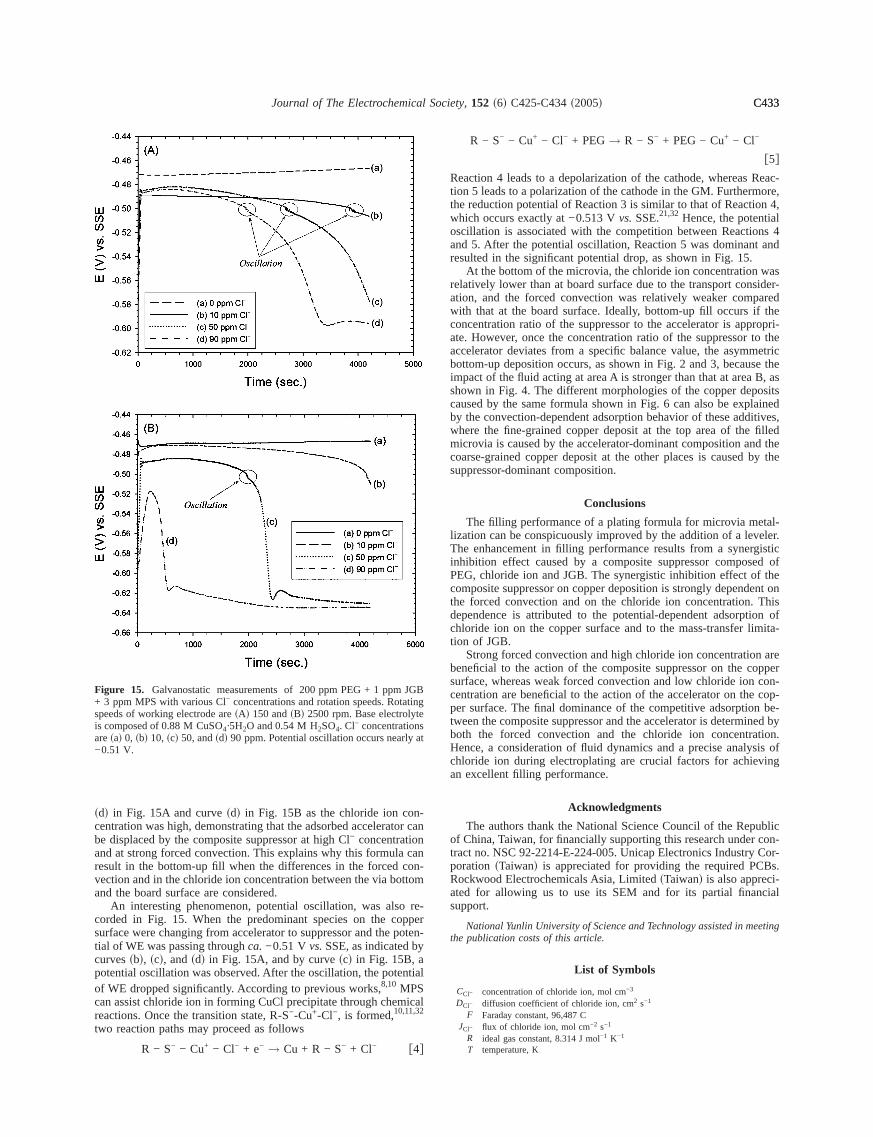
An interesting phenomenon, potential oscillation, was alsocorded in Fig. 15. When the predominant species on the cosurface were changing from accelerator to suppressor and thetial of WE was passing throughca.−0.51 Vvs.SSE, as indicated bcurves~b!, ~c!, and~d! in Fig. 15A, and by curve~c! in Fig. 15B, apotential oscillation was observed. After the oscillation, the poteof WE dropped significantly. According to previous works,8,10 MPScan assist chloride ion in forming CuCl precipitate through chemreactions. Once the transition state, R-S−-Cu+-Cl−, is formed,10,11,32
two reaction paths may proceed as follows
R − S− − Cu+ − Cl− + e− → Cu + R − S− + Cl− f4g
Figure 15. Galvanostatic measurements of 200 ppm PEG + 1 ppm+ 3 ppm MPS with various Cl− concentrations and rotation speeds. Rotaspeeds of working electrode are~A! 150 and~B! 2500 rpm. Base electrolyis composed of 0.88 M CuSO4·5H2O and 0.54 M H2SO4. Cl− concentrationare~a! 0, ~b! 10, ~c! 50, and~d! 90 ppm. Potential oscillation occurs nearly−0.51 V.
n
r-
R − S− − Cu+ − Cl− + PEG→ R − S− + PEG − Cu+ − Cl−
f5gReaction 4 leads to a depolarization of the cathode, whereastion 5 leads to a polarization of the cathode in the GM. Furthermthe reduction potential of Reaction 3 is similar to that of Reactiowhich occurs exactly at −0.513 Vvs.SSE.21,32 Hence, the potentioscillation is associated with the competition between Reactioand 5. After the potential oscillation, Reaction 5 was dominantresulted in the significant potential drop, as shown in Fig. 15.
At the bottom of the microvia, the chloride ion concentrationrelatively lower than at board surface due to the transport conation, and the forced convection was relatively weaker compwith that at the board surface. Ideally, bottom-up fill occurs ifconcentration ratio of the suppressor to the accelerator is appate. However, once the concentration ratio of the suppressoraccelerator deviates from a specific balance value, the asymbottom-up deposition occurs, as shown in Fig. 2 and 3, becauimpact of the fluid acting at area A is stronger than that at areashown in Fig. 4. The different morphologies of the copper depcaused by the same formula shown in Fig. 6 can also be expby the convection-dependent adsorption behavior of these addwhere the fine-grained copper deposit at the top area of themicrovia is caused by the accelerator-dominant composition ancoarse-grained copper deposit at the other places is causedsuppressor-dominant composition.
Conclusions
The filling performance of a plating formula for microvia melization can be conspicuously improved by the addition of a levThe enhancement in filling performance results from a synerinhibition effect caused by a composite suppressor composPEG, chloride ion and JGB. The synergistic inhibition effect ofcomposite suppressor on copper deposition is strongly dependthe forced convection and on the chloride ion concentration.dependence is attributed to the potential-dependent adsorptchloride ion on the copper surface and to the mass-transfer ltion of JGB.
Strong forced convection and high chloride ion concentratiobeneficial to the action of the composite suppressor on the csurface, whereas weak forced convection and low chloride ioncentration are beneficial to the action of the accelerator on theper surface. The final dominance of the competitive adsorptiotween the composite suppressor and the accelerator is determiboth the forced convection and the chloride ion concentraHence, a consideration of fluid dynamics and a precise analychloride ion during electroplating are crucial factors for achiean excellent filling performance.
Acknowledgments
The authors thank the National Science Council of the Repof China, Taiwan, for financially supporting this research undertract no. NSC 92-2214-E-224-005. Unicap Electronics Industryporation ~Taiwan! is appreciated for providing the required PCRockwood Electrochemicals Asia, Limited~Taiwan! is also apprecated for allowing us to use its SEM and for its partial finansupport.
National Yunlin University of Science and Technology assisted in methe publication costs of this article.
List of Symbols
CCl− concentration of chloride ion, mol cm−3
DCl− diffusion coefficient of chloride ion, cm2 s−1
F Faraday constant, 96,487 CJCl− flux of chloride ion, mol cm−2 s−1
R ideal gas constant, 8.314 J mol−1 K−1
T temperature, K

. R.
ashi,
u
shino,
te
Ap-
.
C434 Journal of The Electrochemical Society, 152 ~6! C425-C434~2005!C434
v velocity of bulk solution flow, cm s−1
zCl− charge of chloride ion
Greek
F electrostatic potential, V
References1. J. J. Kelly and A. C. West,Electrochem. Solid-State Lett., 2, 561 ~1999!.2. T. P. Moffat, J. E. Bonevich, W. H. Huber, A. Stanishevsky, D. R. Kelly, G
Stafford, and D. Josell,J. Electrochem. Soc., 147, 4524~2000!.3. P. Taephaisitphongse, Y. Cao, and A. C. West,J. Electrochem. Soc., 148, C492
~2001!.4. K. Kondo, T. Matsumoto, and K. Watanabe,J. Electrochem. Soc., 151, C250
~2004!.5. T. Kobayashi, J. Kawasaki, K. Mihara, and H. Honma,Electrochim. Acta, 47, 85
~2001!.6. S. Miura and H. Honma,Surf. Coat. Technol., 169-170, 91 ~2003!.7. M. Lefebvre, G. Allardyce, M. Seita, H. Tsuchida, M. Kusaka, and S. Hay
Circuit World, 29, 9 ~2003!.8. W.-P. Dow, H.-S. Huang, and Z. Lin,Electrochem. Solid-State Lett., 6, C134
~2003!.9. W.-P. Dow and H.-H. Chen,Circuit World, 30, 33 ~2004!.
10. W.-P. Dow and H.-S. Huang,J. Electrochem. Soc., 152, C67 ~2005!.11. W.-P. Dow, H.-S. Huang, M.-Y. Yen, and H.-H. Chen,J. Electrochem. Soc., 152,
C77 ~2005!.12. M. Yokoi, S. Konishi, and T. Hayashi,Denki Kagaku oyobi Kogyo Butsuri Kagak,
52, 218 ~1984!.
13. K. Doblhofer, S. Wasle, D. M. Soares, K. G. Weil, and G. Ertl,J. Electrochem.Soc., 150, C657~2003!.14. Z. V. Feng, X. Li, and A. A. Gewirth,J. Phys. Chem. B, 107, 9415~2003!.15. K. Kondo, N. Yamakawa, Z. Tanaka, and K. Hayashi,J. Electroanal. Chem., 559,
137 ~2003!.16. J. Reid,Jpn. J. Appl. Phys., Part 1, 40, 2650~2001!.17. J.-J. Sun, K. Kondo, T. Okamura, S. Oh, M. Tomisaka, H. Yonemura, M. Ho
and K. Takahashi,J. Electrochem. Soc., 150, G355~2003!.18. T. P. Moffat, D. Wheeler, W. H. Huber, and D. Josell,Electrochem. Solid-Sta
Lett., 4, C26 ~2001!.19. A. C. West, S. Mayer, and J. Reid,Electrochem. Solid-State Lett., 4, C50 ~2001!.20. Z. Nagy, J. P. Blaudeau, N. C. Hung, L. A. Curtiss, and D. J. Zurawski,J. Elec-
trochem. Soc., 142, L87 ~1995!.21. D. M. Soares, S. Wasle, K. G. Weil, and K. Doblhofer,J. Electroanal. Chem., 532,
353 ~2002!.22. G. M. Brown and G. A. Hope,J. Electroanal. Chem., 405, 211 ~1996!.23. G. M. Brown and G. A. Hope,J. Electroanal. Chem., 413, 153 ~1996!.24. J. P. Healy, D. Pletcher, and M. Goodenough,J. Electroanal. Chem., 338, 155
~1992!.25. A. J. Bard and L. R. Faulkner,Electrochemical Methods, Fundamentals and
plications, 2nd ed., p. 137, John Wiley & Sons, Inc., New York~2001!.26. M. E. Biggin and A. A. Gewirth,J. Electrochem. Soc., 148, C339~2001!.27. M. Kang and A. A. Gewirth,J. Electrochem. Soc., 150, C426~2003!.28. G. G. Láng, M. Ujvári, and G. Horányi,J. Electroanal. Chem., 522, 179 ~2002!.29. C. Gabrielli, P. Mocoteguy, H. Perrot, and R. Wiart,J. Electroanal. Chem., 572,
367 ~2004!.30. F. K. Crundwell,Electrochim. Acta, 37, 2707~1992!.31. M. Itagaki, M. Tagaki, and K. Watanabe,Corros. Sci., 38, 1109~1996!.32. P. M. Vereecken, R. A. Binstead, H. Deligianni, and P. C. Andricacos,IBM J. Res
Dev., 49, 3 ~2005!.