initial design (2)
DESCRIPTION
project of feraTRANSCRIPT
PROJECT GUIDE: Mr. Madhu A.K
(Asst. Professor,Dept. of Mechanical Engineering)
SUBMITTED BY :
Deepak Soman
Deepak Jose
Dinoop P .M
Dominic Joseph
Achu .B
Arjun .P.K
PREFACE
The aim of this pamphlet is to provide an detailed report of our Project in theory, in
mechanisms and design calculations involved and to briefly state the technological relevance of
Nuclear Fusion Research to our future.
This project represents Team Fusions aim and approach, along with a rough outline of the
feasibility of the project.
While most of the content has been hand typed, we have included some text directly from
books and various sources, as we felt they explained the concepts in the most apt manner.
.………………………….
Team Fusion Representative
ABSTRACT
The project includes building a Fusion Reactor. The design is based on typical IEC
(Inertial Electrostatic Confinement) fusion devices which use high-voltage power supplies,
pressurized deuterium gas, and stainless steel construction. Simplification of the chamber
construction, high-voltage power supply, and deuterium delivery system would allow researchers
to focus on more pertinent issues.
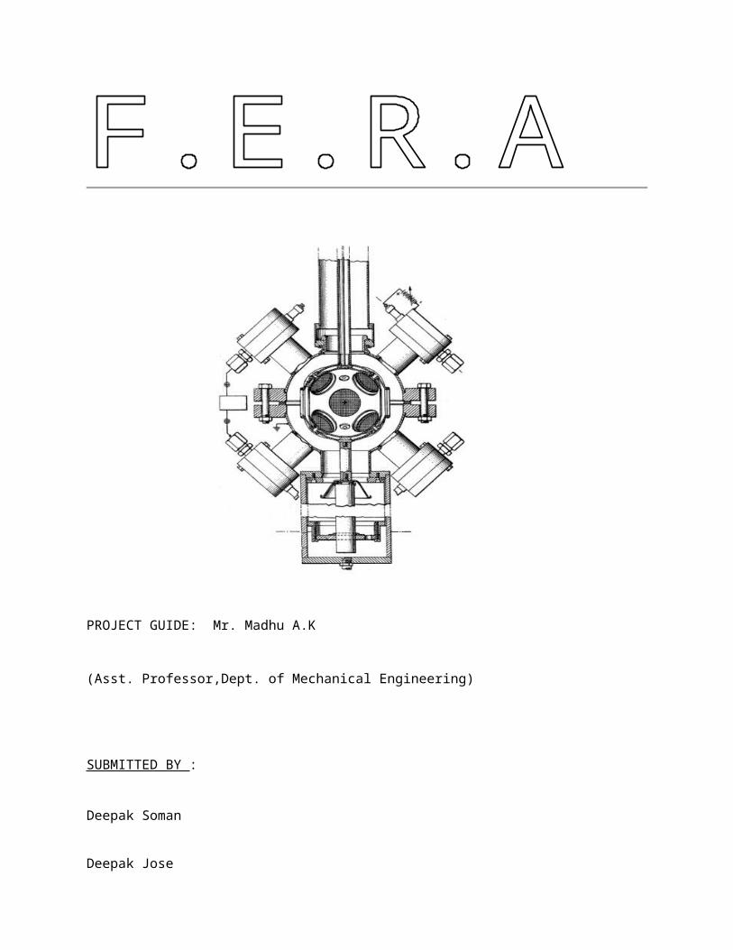
Our design is based on the Farnsworth- Hirch Fusor. This design was patented on 1968, June
and early devices were constructed as early as 1960s. This device would essentially be of table
top construction, with practically no dangers of radiation (as proved by fusioneers). We do not
intend to make a power plant magnitude fusion reactor as such a reactor has never been built, but
merely a small laboratory scale fusion producing device intended for research purposes, that uses
the least amount of resources to produce fusion.
On July 2007, India’s Union Cabinet approved Indian participation in the ITER
project. The project titled Indian Participation in International Thermonuclear Experimental
Reactor, at a base cost of Rs.2500 crore. The FE component calculated at base cost will be
Rs.1129 crore. Hence, our project is also aimed to support India’s efforts as it tries to meets
Fusion challenges.
Such a devise has never been built in India. Fusion as well as Plasma studies have been
extremely scarce in India. It’s high time we rekindle Nuclear Research among Indian students,
who still vision it as something impossible.
CONTENTS
OBJECTIVES
LITERATURE SURVEY
INTRODUCTION
METHODS OF FUSION
HOW TO PRODUCE 300 MILLION KELVIN?
PLASMA PHYSICS
TYPE OF I.E.C REACTORS
PHYSICAL DESCRIPTION OF I.E.C RECATORS
CONSTRUCTIONAL DETAILS
DESIGN CRITERIA
BASIC ASSUMPTIONS
CAD MODULE
DETAILED DESIGN CRITERIA
FUSION RATE
VOLTAGE REQUIREMENTS
VACUUM REQUIREMENTS
FUEL SUPPLY
VACUUM CHAMBER DESIGN
MATERIAL SELSECTION
CHAMBER WALL TEMPERATURE
AIR VELOCITY FOR CONVECTION
SPHERE THICKNESS
CYLINDRICAL PIPE THICKNESS
CYLINDRICAL PIPE THICKNESS( FROM GRAPH)
DESIGN OF FLANGES
DESIGN OF WELDED JOINTS
DESIGN FOR O-RING FITTINGS
APPROACH TO OUR PROJECT
PHASE 1
PHASE 2
PHASE 3
CONCLUSION
BIBLIOGRAPHY
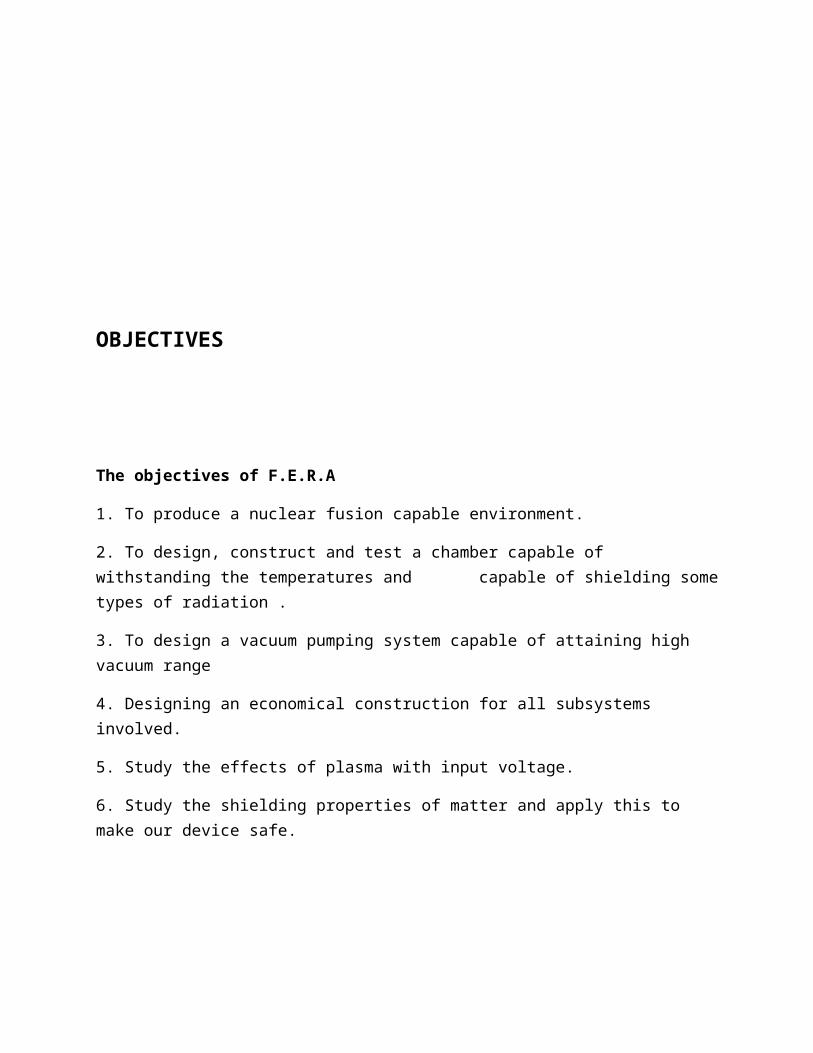
OBJECTIVES
The objectives of F.E.R.A
1. To produce a nuclear fusion capable environment.
2. To design, construct and test a chamber capable of withstanding the temperatures and capable of shielding some types of radiation .
3. To design a vacuum pumping system capable of attaining high vacuum range
4. Designing an economical construction for all subsystems involved.
5. Study the effects of plasma with input voltage.
6. Study the shielding properties of matter and apply this to make our device safe.
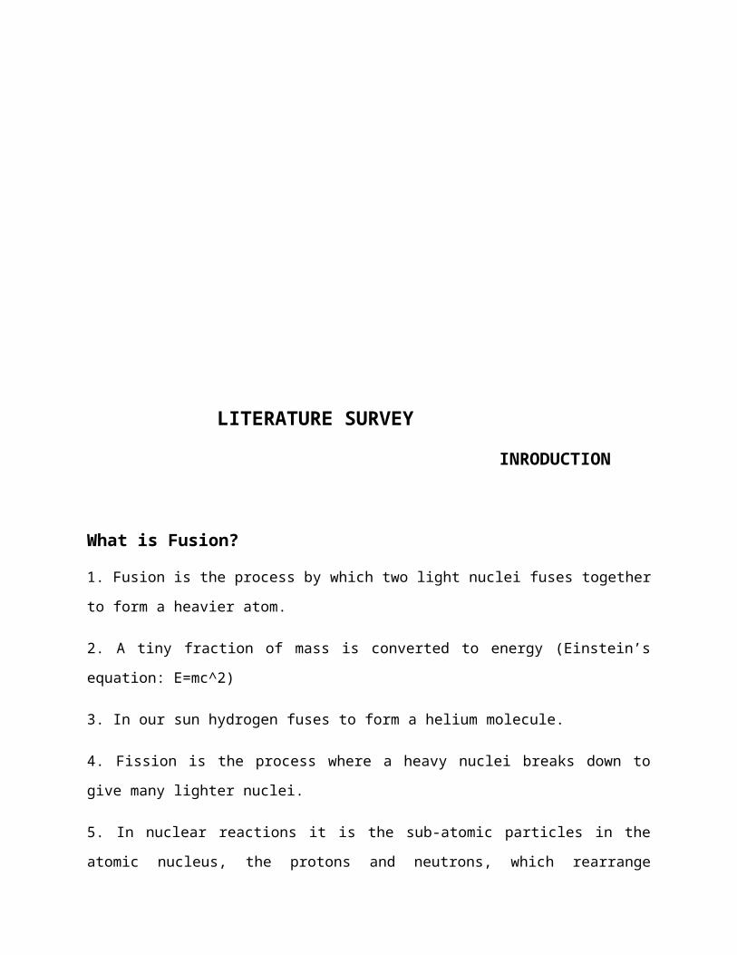
LITERATURE SURVEY
INRODUCTION
What is Fusion?
1. Fusion is the process by which two light nuclei fuses together to form a heavier atom.
2. A tiny fraction of mass is converted to energy (Einstein’s equation: E=mc^2)
3. In our sun hydrogen fuses to form a helium molecule.
4. Fission is the process where a heavy nuclei breaks down to give many lighter nuclei.
5. In nuclear reactions it is the sub-atomic particles in the atomic nucleus, the protons and
neutrons, which rearrange themselves to form new elements or isotopes with more stable nuclei.
In this case the energy released by the reaction in the form of kinetic energy (e.g. heat) and
electromagnetic energy (e.g.: gamma radiation) is millions of times greater.
6. The great attractions of nuclear fusion as an energy source are that the fuel, mostly isotopes of
hydrogen, is plentiful and easy to obtain, and the elements produced as a result of the fusion are
usually light and stable atoms rather than the heavy radioactive products which result from
nuclear fission.
7. The potential release of energy per unit mass of the fuel is much higher in the case of fusion
than in fission since reactions allowing greater increases in binding energy are possible with
fusion reactions.
8. All molecules want to be stable; they want to attain the middle position in a periodic table.
Fission is the process used by heavier atoms to become stable. Fusion is the process for lighter
atoms for attaining stability.
Advantages
1. The fuel for fusion reactions is readily available. Deuterium and Tritium are virtually
inexhaustible.
2. Unlike the burning of coal or other fossil fuels, fusion does not emit harmful toxins into the
atmosphere. The combustion of most fossil fuels involves some form of the reaction
C + O2(g) --> CO2(g) + heat
3. The carbon dioxide (CO2(g)) emitted by this reaction contributes to the global warning/so-
called "Greenhouse Effect. Fusion, however, produces only helium, a gas that is already in
abundance in the atmosphere and will not contribute to global warming.
Disadvantages
1. Scientists have not yet been able to contain a fusion reaction long enough for there to be a net
energy gain.
2. Many countries are phasing out fusion research because of the failure to reach a breakthrough
Why is Fusion so Hard to do?
While it seems simple, nuclear fusion tends to be extremely hard:
Nuclei make repelling each other their number one priority. It takes a lot of effort to push nuclei
close enough together to get nuclear reactions to happen.The easy way to overcome that
repulsion is to accelerate particles towards each other so that they have enough energy to
overcome that barrier of repulsion. That's exactly what happens in particle accelerators; a typical
accelerator might accelerate protons to 2 MeV1 and smash them into a target.
Along with space and money requirements, electrostatic particle accelerators are typically
limited to small bunches of particles and require extremely high voltages to perform.
The electrostatic force repels two nuclei because they’re oppositely charged(it’s the entire
“like charges repel” mechanism). This force is normally verystrong on the scales we’re talking
about—it’s strong enough to prevent things from fusing together when collisions happen, for
example. Even if two Jumbo Jets crashed into each other at 600 miles per hour, the resultant
debris and catastrophe doesn’t induce fusion. It’s harder than that.
METHODS OF FUSION
1. Tokamak /Stellerator (Magnetic Confinement)
Magnets exert a force on electrically charged particles, and in a plasma (usually a very energetic
state of matter, at around 30-100 million Kelvin), the electrons have already been literally ripped
off of the hydrogen atoms-they’re all charged and running around, loose and fast as heck.
Therefore they can use incredibly strong magnets to restrict and bind this charged body. There’s
no gravity or other mechanism to help them along.
2 The National Ignition Facility (Lasers/Inertial Confinement)
Another method of fusion is to get a small pellet of solid hydrogen, coat it with plastic or
something else that will melt at high temperatures and then fire lots of really big lasers at it. The
lasers make the plastic hot enough that it literally “explodes”, forcing the solid hydrogen inward
and inducing conditions with enough pressure and temperature to induce fusion.
3 Cold Fusion
There are whole subsets of techniques that call themselves “cold fusion” and most of them don’t
work. If they do work, they haven’t been able to reproduce it or get antitative evidence. We’ll
ignore them for the moment.
4 The Inertial Electrostatic Confinement
In a very low density gas, lighter particles can travel about a meter without colliding into one
another, hence atoms can be accelerated into a central point.
The Fusor exploits the natural enemy of nuclear fusion physicists—that nasty electrostatic force
that repels the atoms from getting together. The Fusor accelerates ions by placing them in a very
high voltage differential situation; the ions will naturally accelerate to an area of negative charge
due to the electrostatic force.
What would happen if that negative terminal wasn’t solid, but was instead a grid, so that
the ions would continue traveling at high speeds past the terminal? With a spherical, grid-like
negative electrode, hydrogen ions naturally accelerate toward it, and toward the center of the
system. However, since the grid actually has space for them to pass in between, the hydrogen
ions will go through that route. Of course, all the hydrogen ions in the system are heading for the
center—they’ll naturally collide at the center of the negative electrode
How to produce 350 MILLION Kelvin ?
Since temperature is just a reading of atoms’ average kinetic energy, if you’re given an amount
of energy, you can calculate a particle’s temperature as well (if you know it’s mass).
One electron volt = 1.60217653 ×10⁻¹⁹ J.
One electron volt = 11605 Kelvin.
One electron volt= energy gathered by an electron when accelerated by 1 volt potential
Therefore, 30000V= 30000 electron volts =30000×11605= approx 350 million Kelvin.
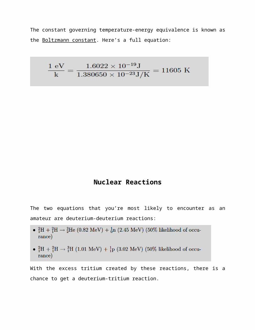
The constant governing temperature-energy equivalence is known as the Boltzmann constant.
Here’s a full equation:
Nuclear Reactions
The two equations that you’re most likely to encounter as an amateur are deuterium-deuterium
reactions:
With the excess tritium created by these reactions, there is a chance to get a deuterium-tritium
reaction.
The amount of reactions is highly related to the “nuclear cross section,”which is the amount of
apparent area that an atom will present to be reactedwith. (Higher is better.)
PLASMA PHYSICS
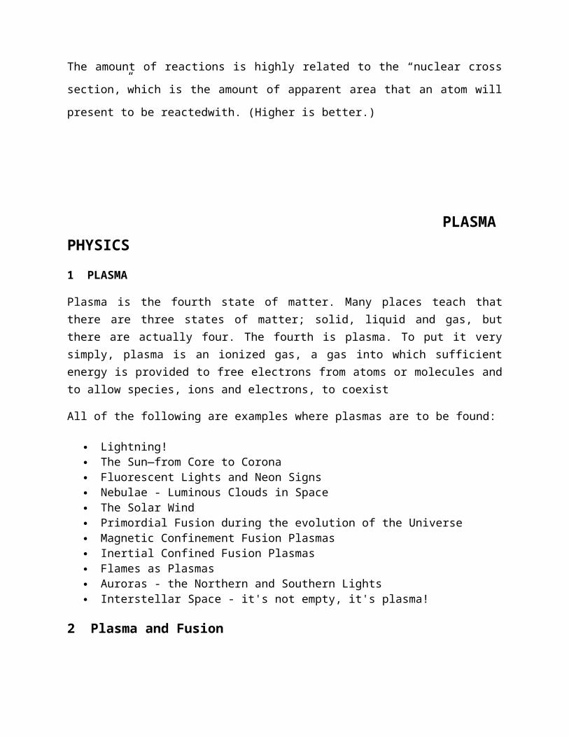
1 PLASMA
Plasma is the fourth state of matter. Many places teach that there are three states of matter; solid, liquid and gas, but there are actually four. The fourth is plasma. To put it very simply, plasma is an ionized gas, a gas into which sufficient energy is provided to free electrons from atoms or molecules and to allow species, ions and electrons, to coexist
All of the following are examples where plasmas are to be found:
Lightning! The Sun—from Core to Corona Fluorescent Lights and Neon Signs Nebulae - Luminous Clouds in Space The Solar Wind Primordial Fusion during the evolution of the Universe Magnetic Confinement Fusion Plasmas Inertial Confined Fusion Plasmas Flames as Plasmas Auroras - the Northern and Southern Lights Interstellar Space - it's not empty, it's plasma!
2 Plasma and Fusion
Plasma is the so-called “fourth state of matter”, a cloud of ionized gas possessing many
unique properties. Within this cloud of ionized gasses the process of fusion can be initiated under
the correct circumstances. The process of fusion is far superior to that of fission because it leaves
less nuclear waste that only remains for a short period of time rather than hundreds of thousands
if not millions of years.
At a certain temperature plasma begins to maintain itself allowing for the harvesting of
energy released by the fusion of tritium and deuterium; to maintain this temperature the plasma
cannot touch the walls of the containing chamber because much heat would be lost causing a
failure in the self-sustainment of the plasma burn .Thus, plasma was the most difficult problem
encountered in the subject of fusion energy to this point.
TYPES OF I.E.C REACTORS
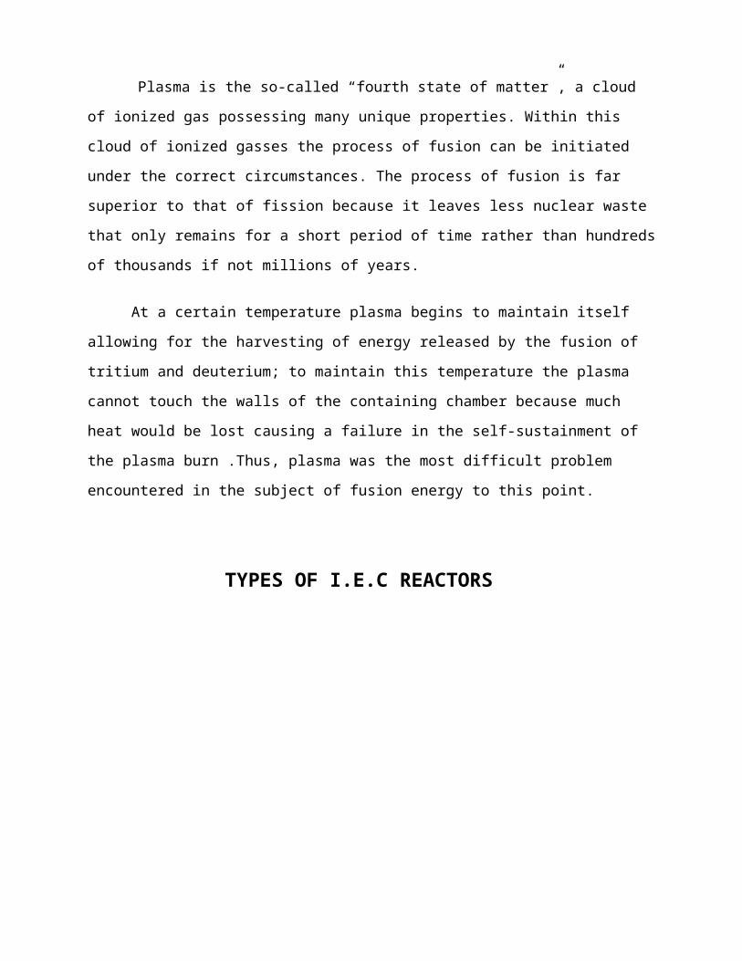
1 FARNSWORTH-HIRCH FUSOR
OPERATION
• Central grid is negatively biased• Ions oscillate in electrostatic field• Ions collide at focal point and fuse• Fusion generated high energy neutrons and protons
MAJOR LOSSES
Grid heating due to ion bombardment causes thermionic electron emission, thereby increasing reactor power draw and generating unwanted x-ray radiation
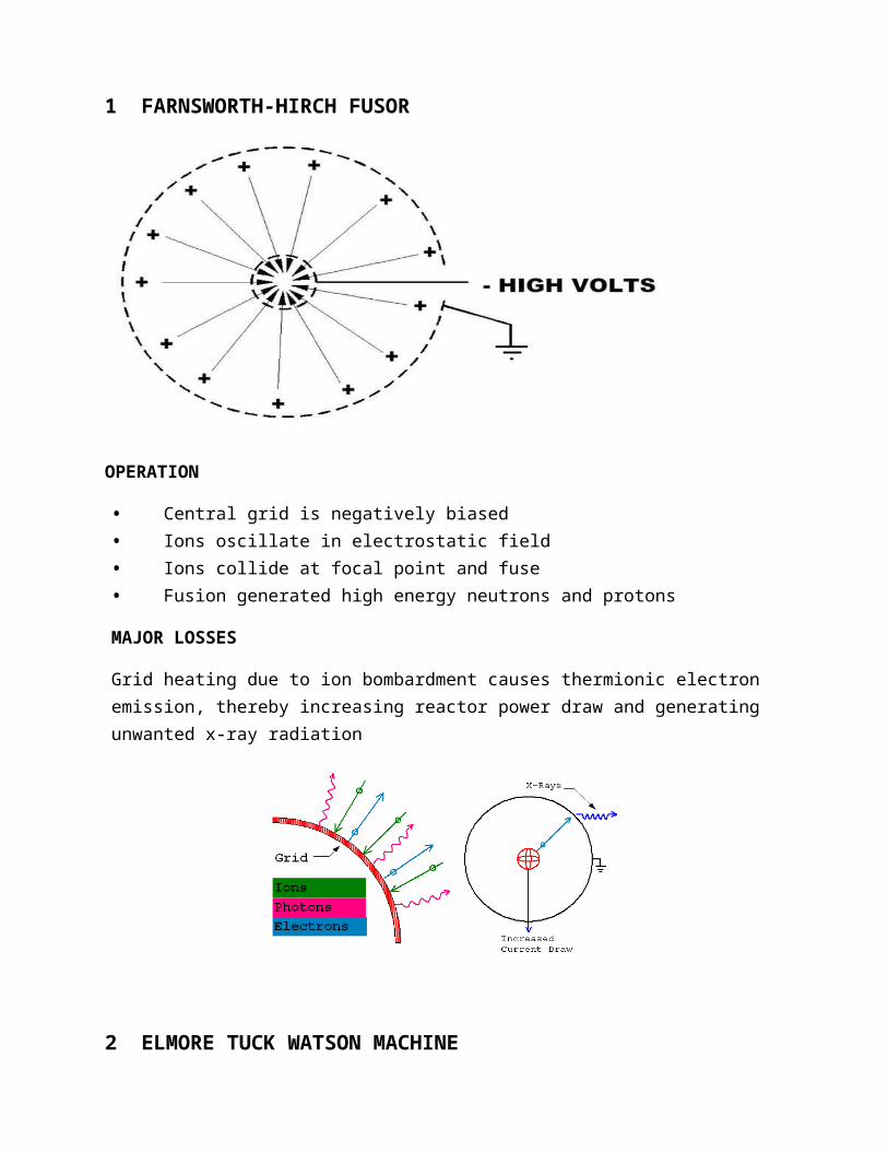
2 ELMORE TUCK WATSON MACHINE
OPERATION
• Grids accelerate electrons rather than ions.
• Electron potential well accelerates the ions.
• The ions experience no grid losses.
• But the electrons experience high grid losses. Net power still low.
• Both electron and ion confinement is dynamic, so this is Inertial “Electrodynamic”
fusion, (IEF)
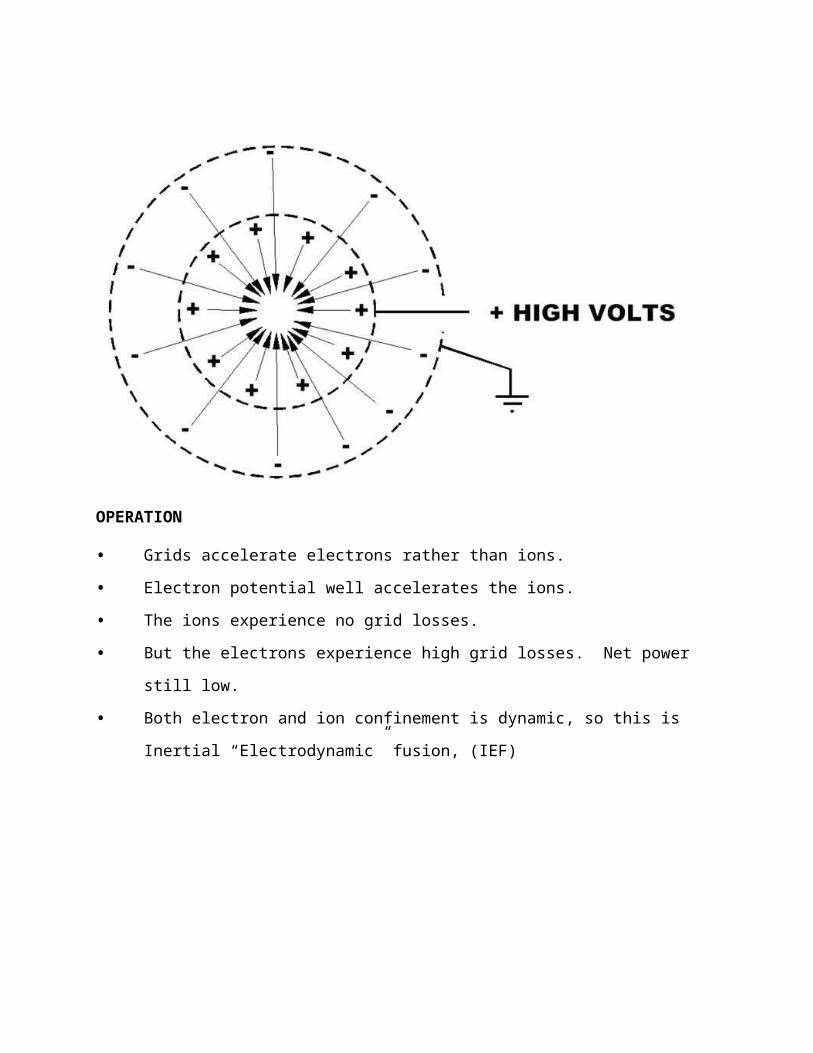
3 BUSSARD REACTOR
Bussard’s IEF Approach
• Electron grid of ETW machine replaced with
magnetically-insulated “magrid”
• Electrons several thousand times lighter than fusion
fuel ions … fields that can’t hold ions easily confine
electrons.
• Remember, this is dynamic confinement, and both
electrons and ions are in constant, vigorous motion.
What did Bussard’s reactor accomplish??
Finally confined electrons as the computer models said it should.
Demonstrated the importance of two fine details of magrid constructions that prior devices had
ignored.
Worked about a thousand times better than previous models.
Four replicate fusion runs before it fried
PHYSICAL DESCRIPTION OF I.E.C REACTORS
The simple Fusor is the best example of how fusion can be done on the cheap.
The unit consists of an electrically conductive, vacuum tight, metallic outer shell.
Within the outer spherical shell casing is found a single, centrally located, electrically conductive
spherical grid that is more or less transparent in that it is made up of a hollow, wire ball. This
"central" or "inner" grid is supported by and electrically connected to the outside world, by an
insulated, electrically conductive stalk or post which is run through a "feed through" insulator
that is also vacuum tight.
There are other add-ons that facilitate operational control and observation, such as view ports,
vacuum guage ports and the mandatory vacuum system connection which allows the air inside to
be removed. There is also a mandatory gas line which allows the introduction of a fusionable
gas. This gas is always deuterium in a simple amateur Fusor.
1 DEFINITION
The Fusor can be defined as an “electro statically focused, and accelerated, deuteron collider
type of fusion device" relying on "inertial electrostatic confinement" to allow fusion to take place
in "velocity space".
2 FUNCTION
The Fusor, as a form of accelerator, is a closed electrical system, voltage gradient device. It
demands input energy to achieve fusion. It will not self sustain or achieve "ignition" as is
classically sought in an energy producing fusion reactor. (None of this desirable breed has ever
existed on earth). As such, the Fusor hasn’t been able to produce much energy.
Stated verbally, d-d can make a reaction occur that yields a Helium 3 atom, (stable), with a
kinetic energy of .82 Mev and a Neutron of 2.45 Mev kinetic energy. 50% of the time, d-d can
also form a reaction that yields a tritium atom, (radioactive), with a kinetic energy of 1 Mev and
a proton of 3 Mev kinetic energy.
All of these particles except the neutron will NEVER leave the Fusor, but collide with other gas
atoms in the device and or the metal outer shell wall. here, their energy will be transformed into
fusion energy HEAT and X-rays/gamma rays. NOTE** these X-rays will be of massive energy,
(up to 3 Mev!), but result in a normal, external, net x-ray current in the sub atto-ampere range
and effectively be undetectable due to their large penetrating power. The neutrons will pass right
through the casing as if it were not there. Thus, we say that the Fusor is a "neutron producing
device".
There is a third reaction possible about every 10,000 fusions that is not part of any real
discussion of d-d "hot" fusion and it is:
d + d = He4 + gamma ray with about ~20 Mev of energy distributed among the two particles.
3 PHYSICAL PROCESS
The Fusor device, first, has all the air extracted via a vacuum pump. This is much easier said
than done. Much time, expense and effort is put forth in attaining this mandatory goal.
The required pressure for evacuation is a minimum of one micron or 10e-3 torr. It is far better if
one can achieve lower pressures in the 10e-4 to 10e-6 range. Such higher vacuum levels would
indicate a more professional job and represent very "clean" and well sealed Fusor.
Ultimately, any vacuum achieved will be filled back up to a pressure of about 10 microns (10e-2
torr) with the reactant gas, deuterium, from which the fusion is actually derived. Getting the gas
there and regulating it is another mission that must be accomplished for fusion to take place.
This gives us a Fusor device that is evacuated of all air and depressurized to only about
1/100,000th of an atmosphere of pure deuterium gas. There is still a vacuum in the vessel,
obviously, but all the gas in the vessel is a fusion ready, deuterium gas.
To make fusion happen, we must apply energy externally to the device. This energy is electrical
energy. This electrical energy is applied as a very high voltage gradient across the two Fusor
electrical components, the outer shell and the inner grid. This potential gradient can be as low as
a few kilovolts to cause fusion to commence, though over 20 kilovolts is needed to make readily
detectable fusion.
This application of electrical energy does two very important things.
1. It supplies the energy necessary to strip the outershell electrons from deuterium gas atoms.
This turns them into "ions" called DEUTERONS which are a naked hydrogen nucleus with one
neutron and one proton in it.
2. The potential gradient established between the negative inner grid and the positive outer
spherical shell forces the, now positive, deuterons created within the inter grid gas region to push
away or be repelled from the positive outer shell and rush or be accelerated towards the highly
negative inner grid. (Opposite charges attract, like charges repel). It only takes a minimum
gradient of 14 volts or so to ionize a deuterium atom, transforming it into a deuteron. With such a
huge gradient as we apply, deuterons can be created over the entire fusion gas volume!! This
process is called field ionization. Most of this ionization occurs near the inner grid due to the
small radius wires. Deuterons created here are lost to fusion.
CONSTRUCTION DETAILS OF AN I.E.C REACTOR
SUBSYSTEMS INVOLVED
1. VACUUM CHAMBER2. VACUUM PUMPING SYSTEM3. HIGH VOLTAGE DC SUPPLY
4. NEUTRON DETECTION SYSTEM5. SAFETY SYSTEM
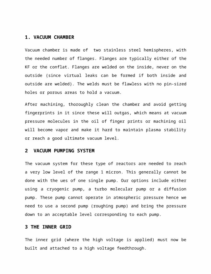
1. VACUUM CHAMBER
Vacuum chamber is made of two stainless steel hemispheres, with the needed number of
flanges. Flanges are typically either of the KF or the conflat. Flanges are welded on the inside,
never on the outside (since virtual leaks can be formed if both inside and outside are welded).
The welds must be flawless with no pin-sized holes or porous areas to hold a vacuum.
After machining, thoroughly clean the chamber and avoid getting fingerprints in it since these
will outgas, which means at vacuum pressure molecules in the oil of finger prints or machining
oil will become vapor and make it hard to maintain plasma stability or reach a good ultimate
vacuum level.
2 VACUUM PUMPING SYSTEM
The vacuum system for these type of reactors are needed to reach a very low level of the range 1
micron. This generally cannot be done with the ues of one single pump. Our options include
either using a cryogenic pump, a turbo molecular pump or a diffusion pump. These pump cannot
operate in atmospheric pressure hence we need to use a second pump (roughing pump) and bring
the pressure down to an acceptable level corresponding to each pump.
3 THE INNER GRID
The inner grid (where the high voltage is applied) must now be built and attached to a high
voltage feedthrough.
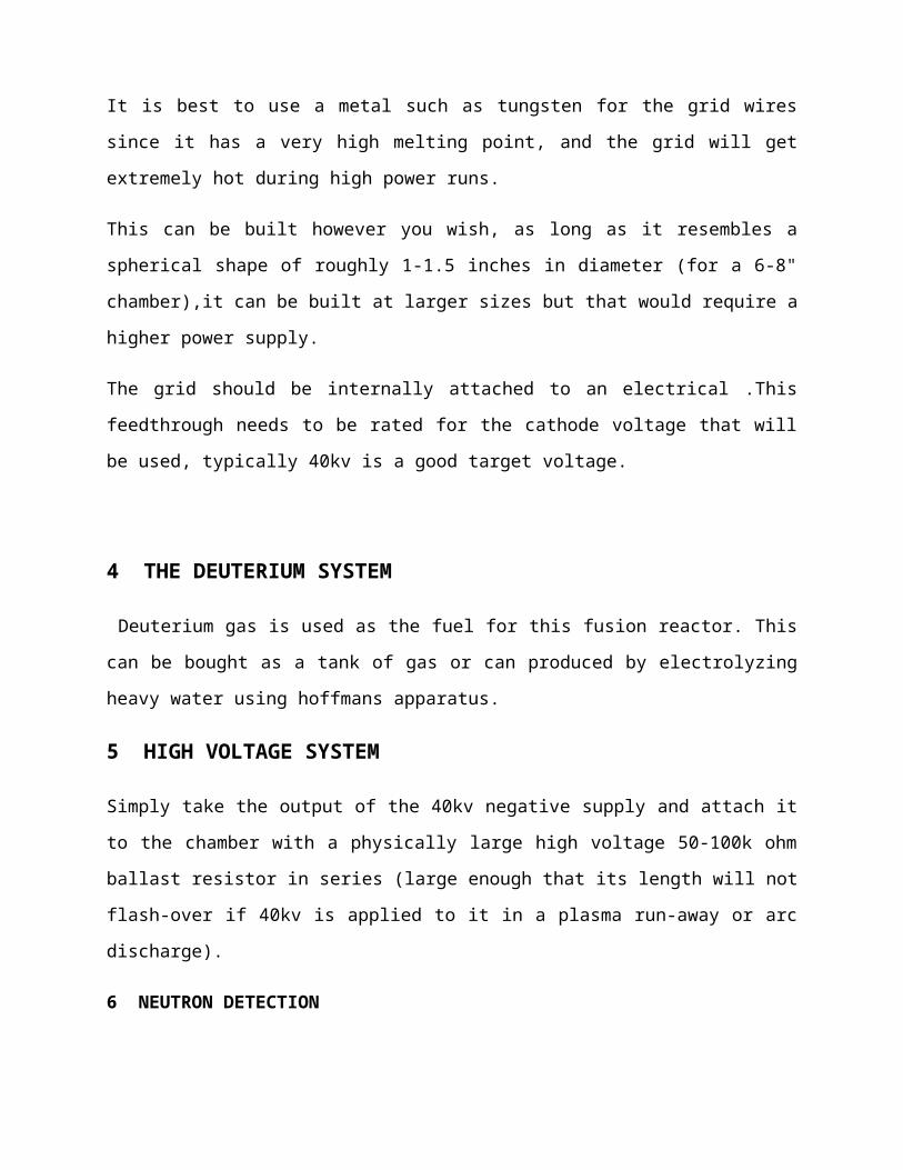
It is best to use a metal such as tungsten for the grid wires since it has a very high melting point,
and the grid will get extremely hot during high power runs.
This can be built however you wish, as long as it resembles a spherical shape of roughly 1-1.5
inches in diameter (for a 6-8" chamber),it can be built at larger sizes but that would require a
higher power supply.
The grid should be internally attached to an electrical .This feedthrough needs to be rated for the
cathode voltage that will be used, typically 40kv is a good target voltage.
4 THE DEUTERIUM SYSTEM
Deuterium gas is used as the fuel for this fusion reactor. This can be bought as a tank of gas or
can produced by electrolyzing heavy water using hoffmans apparatus.
5 HIGH VOLTAGE SYSTEM
Simply take the output of the 40kv negative supply and attach it to the chamber with a physically
large high voltage 50-100k ohm ballast resistor in series (large enough that its length will not
flash-over if 40kv is applied to it in a plasma run-away or arc discharge).
6 NEUTRON DETECTION
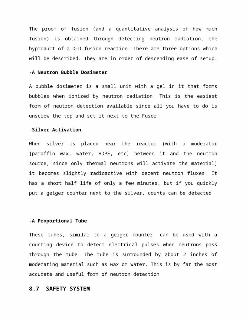
The proof of fusion (and a quantitative analysis of how much fusion) is obtained through
detecting neutron radiation, the byproduct of a D-D fusion reaction. There are three options
which will be described. They are in order of descending ease of setup.
-A Neutron Bubble Dosimeter
A bubble dosimeter is a small unit with a gel in it that forms bubbles when ionized by neutron
radiation. This is the easiest form of neutron detection available since all you have to do is
unscrew the top and set it next to the Fusor.
-Silver Activation
When silver is placed near the reactor (with a moderator [paraffin wax, water, HDPE, etc]
between it and the neutron source, since only thermal neutrons will activate the material) it
becomes slightly radioactive with decent neutron fluxes. It has a short half life of only a few
minutes, but if you quickly put a geiger counter next to the silver, counts can be detected
-A Proportional Tube
These tubes, similar to a geiger counter, can be used with a counting device to detect electrical
pulses when neutrons pass through the tube. The tube is surrounded by about 2 inches of
moderating material such as wax or water. This is by far the most accurate and useful form of
neutron detection
8.7 SAFETY SYSTEM
This comprises of all the components that monitors the reactors working and also the levels of
radiation. It mainly comprises instruments like gieger counter to measure X-ray radiation and
scintillation detectors to monitor neutron emission.
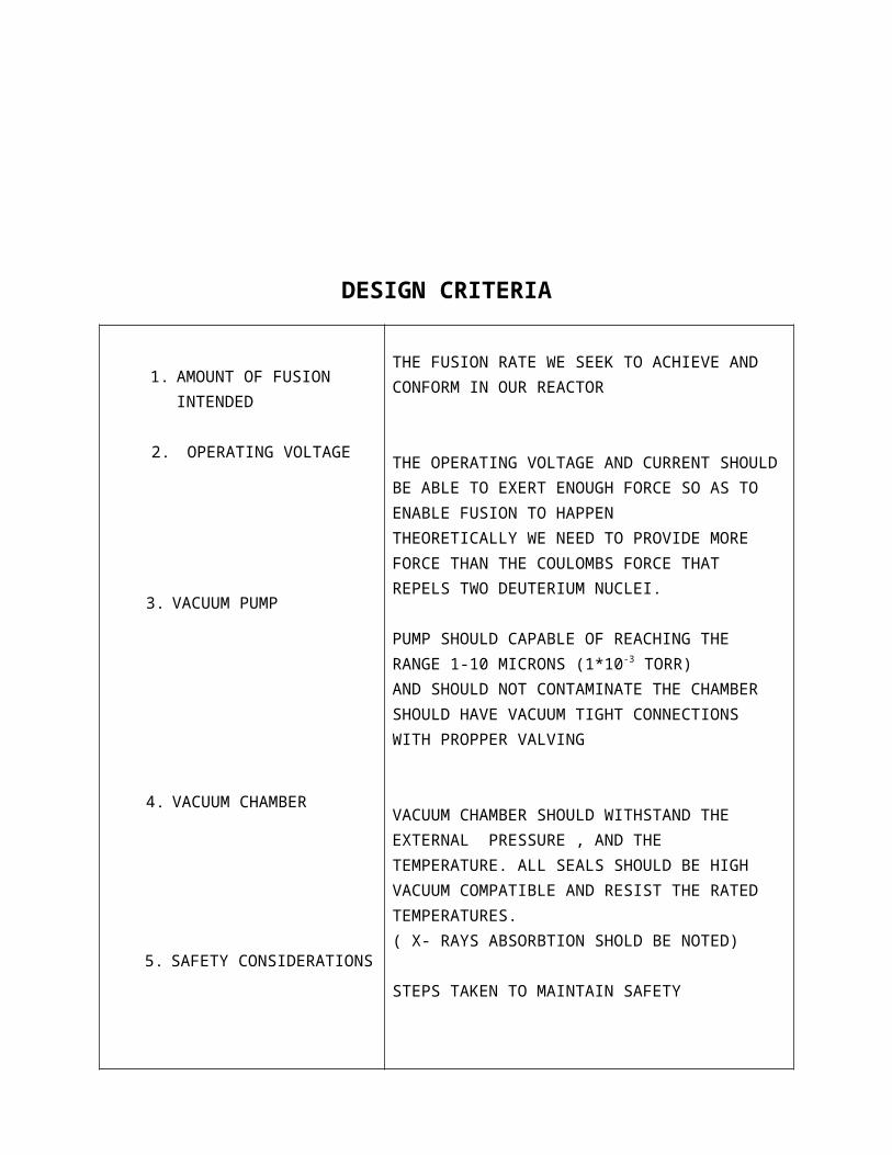
DESIGN CRITERIA
1. AMOUNT OF FUSION INTENDED
2. OPERATING VOLTAGE
3. VACUUM PUMP
4. VACUUM CHAMBER
5. SAFETY CONSIDERATIONS
THE FUSION RATE WE SEEK TO ACHIEVE AND CONFORM IN OUR REACTOR
THE OPERATING VOLTAGE AND CURRENT SHOULD BE ABLE TO EXERT ENOUGH FORCE SO AS TO ENABLE FUSION TO HAPPENTHEORETICALLY WE NEED TO PROVIDE MORE FORCE THAN THE COULOMBS FORCE THAT REPELS TWO DEUTERIUM NUCLEI.
PUMP SHOULD CAPABLE OF REACHING THE RANGE 1-10 MICRONS (1*10-3 TORR)AND SHOULD NOT CONTAMINATE THE CHAMBERSHOULD HAVE VACUUM TIGHT CONNECTIONS WITH PROPPER VALVING
VACUUM CHAMBER SHOULD WITHSTAND THE EXTERNAL PRESSURE , AND THE TEMPERATURE. ALL SEALS SHOULD BE HIGH VACUUM COMPATIBLE AND RESIST THE RATED TEMPERATURES.( X- RAYS ABSORBTION SHOLD BE NOTED)
STEPS TAKEN TO MAINTAIN SAFETY
BASIC ASSUMPTIONS
VACUUM CHAMBER IS CHOSEN TO BE SPHERICAL IN SHAPE.
HEAT LOSS OCCURING WOULD BE 95% OF INPUT POWER
NO OF PORTS REQUIRED ARE 5
- Fuel port - high voltage port
- viewport -pump port
-pressure head port
Feed through used will be a modified spark plug
PRESSURE ON CHAMBER WALLS IS 15 psi (103.4 Kpa)
CAD MODEL
FRONT VIEW BACK VIEW
DETAILED DESIGN SPECIFICATIONS
FUSION RATE
Fusion phenomenon cannot be directly measured directly, the only way to measure this phenomenon is to measure its outputs
As we see from the above reactions, the products coming from the reaction would be having either neutrons or protons with a probability of 0.5 for each, also along with these particles there are electron radiated outwards (beta radiation)
Our design assumes we will isolate all radiations inside the chamber except for neutron radiation; hence we use neutron detection, and use neutron counts as a measure of radiation.
We know that neutrons become hard to detect under the range of 10,000 neutrons/sec;
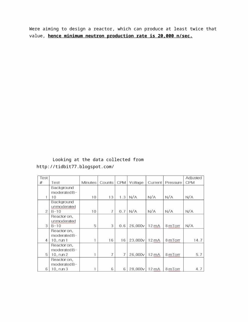
Were aiming to design a reactor, which can produce at least twice that value, hence minimum neutron production rate is 20,000 n/sec.
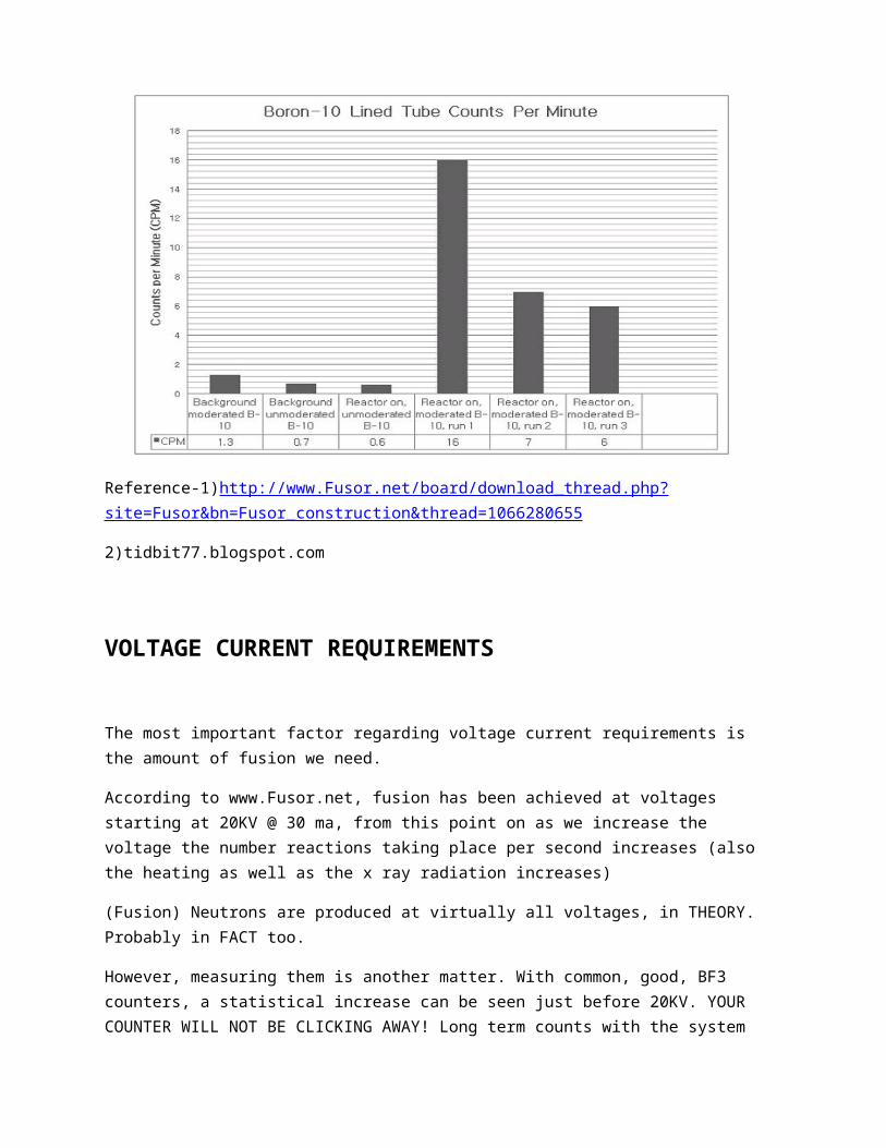
Looking at the data collected from http://tidbit77.blogspot.com/
Reference-1)http://www.Fusor.net/board/download_thread.php?site=Fusor&bn=Fusor_construction&thread=1066280655
2)tidbit77.blogspot.com
VOLTAGE CURRENT REQUIREMENTS
The most important factor regarding voltage current requirements is the amount of fusion we need.
According to www.Fusor.net, fusion has been achieved at voltages starting at 20KV @ 30 ma, from this point on as we increase the voltage the number reactions taking place per second increases (also the heating as well as the x ray radiation increases)
(Fusion) Neutrons are produced at virtually all voltages, in THEORY. Probably in FACT too.
However, measuring them is another matter. With common, good, BF3 counters, a statistical increase can be seen just before 20KV. YOUR COUNTER WILL NOT BE CLICKING AWAY! Long term counts with the system air run vs. deuterium run will show the neutron production provided you can keep the device stable over say a 3-5 minute count period.
Lowest voltage for fusion by different fusioneers is given below.
1. Larry leins 27kv @ 10-20 microns2. Richard Hull 20kv 5-12 microns3. Jason Heidecker 18 kv@10ma, 1micron4. The data from tidbit77.blogspot.com shows the start of fusion occurring at 23kv, 12 ma –
8 microns
Cost analysis- cheapest options
A common neon transformer comes in the range of 10-15 kv@ 30 ma, using a voltage multiplier we can multiply the voltage to a factor of one or two, at the same time the magnitude of current decreases by a factor of one or two.
In order to reach the 40KV and above range the best option is to use an X-ray transformer.
CONCLUSION
Keeping all factors in mind the best alternative seems to be to use a supply in the range of 20 kv and 35 kv (20 kv being the voltage at which fusion starts, but we need a highly sensitive neutron counter for measuring this and 30 kv at which fusion achieved can be measured by less sensitive bubble dosimeter)
NOTE: for all calculations assumed power supply is 30KV @ 30 ma
VACUUM REQUIRED
WE NEED VACUMM FOR
1. TO INCREASE YTHE MEAN FREE PATH* OF DEUTERIUM IONS AND ELECTRONS2. TO INCREASE THE PROBABILITY OF DEUTERIUM IONS COLLIDING TOWARD THE
CENTRE3. IT ALSO PREVENTS HIGH VOLTAGE ARCHING INSIDE OUR CHAMBER
THEORETICALLY, FOR I.E.C TYPE FUSORS anything below ~ 3-5 microns is useless as the glow discharge will not occur As the pressure increases the percentage of the gas that is ionized and participates in fusion goes up. But neutrals (other atoms in chamber) start messing things up. Also, it is more difficult to get high concentrations (%) of deuterium gas without several purges, and/or high feed rates- that consumes the valuable deuterium gas quickly generally the ranges of ~ 5-30 Microns as the target range has been suggested by Dan Tibbett’s in http://www.Fusor.net/board/download_thread.php?site=Fusor&bn=Fusor_vacuum&thread=1302934759
Good mechanical vane pumps can often reach these levels (at least 20-30 Microns). The problem is that they pump very slowly in this region, so they cannot keep up if there is much out gassing as the chamber heats up, or if the plasma increases out gassing/ sputtering. A diffusion pump which pumps much faster in this region (below ~100 Microns) only needs a small portion of its capacity to keep up, and even the small ones may have to be almost valved off to prevent too rapid pump out of the valuable deuterium gas.
SOLUTION:
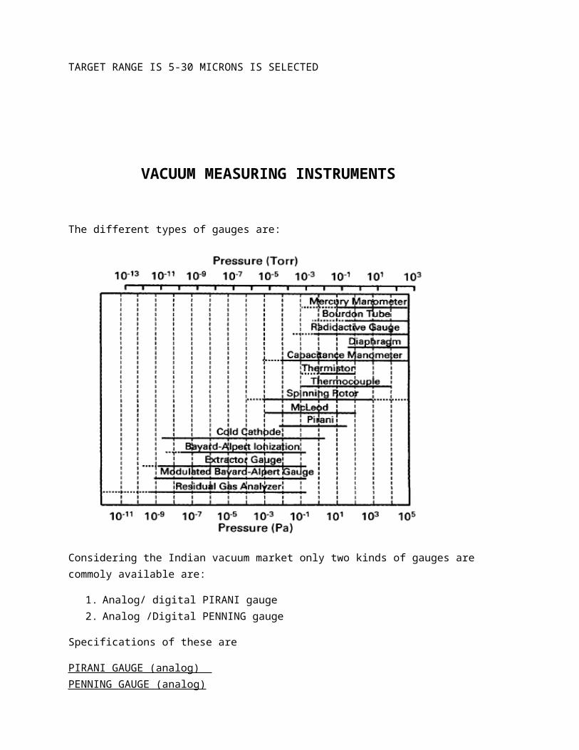
TARGET RANGE IS 5-30 MICRONS IS SELECTED

VACUUM MEASURING INSTRUMENTS
The different types of gauges are:
Considering the Indian vacuum market only two kinds of gauges are commoly available are:
1. Analog/ digital PIRANI gauge2. Analog /Digital PENNING gauge
Specifications of these are
PIRANI GAUGE (analog) PENNING GAUGE (analog)
Type: cold cathode ionization Gauge Thermocouple gauge
Approx price (HHV): 10000rs Approx price(HHV)=12000RS
Other suppliers: 4000rs Other suppliers: 6000rs
Pressure measurement range:0.5 m. bar to 1x10⁻³ m. bar 10-2 to 10-6 m.bar.
SOLUTION:
Since the cheaper pirani gauge satisfies our requirements we, select the pirani gauge.
FUEL SUPPLY
AS OUR PROJECT REVOLVES AROUND ACHIEVING FUSION USING THE SIMPLEST RESOURCES THE FUELS THAT CAN BE CONSIDERED ARE
OF ALL THE ABOVE REACTIONS THE ONE HAVING HIGEST NUCLEAR CROSS SECTION IS (1) BUT THIS INVOLVES TRITIUM WHICH IS VERY EXPENSIVE
THE SECOND HIGEST CROSS SECTION IS FOR DEUTERIUM-DEUTERIUM REACTION WHICH IS CONSIDERABLY CHEAPER, HENCE FUEL CHOSEN IS DEUTERIUM.
NOW, DEUTERIUM IS AVAILABLE FOR SALE IN PURITY OF 98% (NUCLEAR MODERATOR GRADE)
AND 99.8% LAB EXPERIMENT GRADE, ALSO IT IS AVAILABLE AS A SPECIAL WELDING GAS.
LECTURE BOTTLES OF DEUTERIUM ARE IN 10 LITRE AND 30 LITRE RANGE
A SECOND METHOD TO PRODUCE DEUTERIUM DEUTERIM IS TO ELECTROLYZE HEAVY WATER (DEUTERIUM OXIDE) USING HOFFMANS APPARATUS.
EITHER METHOD WOULD REQUIRE A RESERVOIR AND A NEEDLE VALVE FOR MINUTE THROTTLING OF FUEL INTO THE CHAMBER, IN CASE WE USE A LECTURE BOTTLE WE WOULD NEED A PRESSURE REDUCING VALVE AND PRESSURE MEASURING INSTRUMENTS.
VACUUM CHAMBER DESIGN
THIS SECTION DEALS WITH THE CONSTRUCTION OF VACUUM CHAMBER
THIS HAS BEEN DEIVIDED INTI THE FOLLOWING SECTIONS
1) MATERIAL SELECTION2) X RAY ATTENUATION FACTOR3) CHAMBER WALL TEMPERATURE
In this we have assumed 95% of power goes to heat lossAnd input power 30kv at 30ma
4) VELOCITY OF AIRWe had assumed Hi = 50W/m2K, hence we prove what velocity of air would satisfy this
5) CHAMBER WALL THICKNESSIn this we have assumed the shape of chamber to be spherical and the size to be D=8”, and hence we calculate the require thickness
6) CALCULATION OF PIPE THICKNESS7) CALCULATION OF PIPE THICKNESS FROM GRAPHS8) Design of FlANGES9) DESIGN OF WELDED JOINTS10) DESIGN OF VACUUM SEALS
a) MATERIAL SELECTION
Choosing the material for a vacuum chamber often leads to wide discussion of their principal properties. The material parameters design for the vacuum chamber in terms of mechanics could be quite numerous, but there are only three main ones:
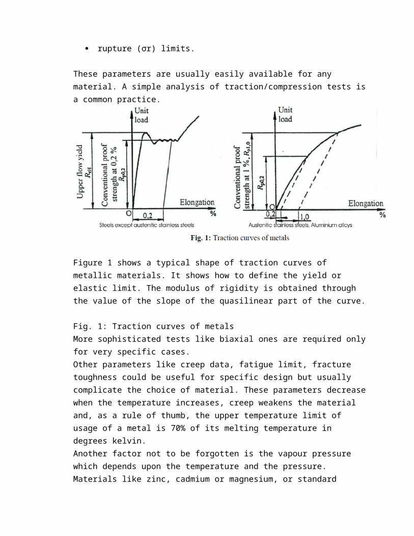
the modulus of rigidity (Young’s modulus: E), the elastic (σ0.2) and rupture (σr) limits.
These parameters are usually easily available for any material. A simple analysis of traction/compression tests is a common practice.
Figure 1 shows a typical shape of traction curves of metallic materials. It shows how to define the yield or elastic limit. The modulus of rigidity is obtained through the value of the slope of the quasilinear part of the curve.
Fig. 1: Traction curves of metalsMore sophisticated tests like biaxial ones are required only for very specific cases.Other parameters like creep data, fatigue limit, fracture toughness could be useful for specific design but usually complicate the choice of material. These parameters decrease when the temperature increases, creep weakens the material and, as a rule of thumb, the upper temperature limit of usage of a metal is 70% of its melting temperature in degrees kelvin. Another factor not to be forgotten is the vapour pressure which depends upon the temperature and the pressure. Materials like zinc, cadmium or magnesium, or standard resins which have significant vapour pressure at low temperature are not acceptable when a bake-out is foreseen.
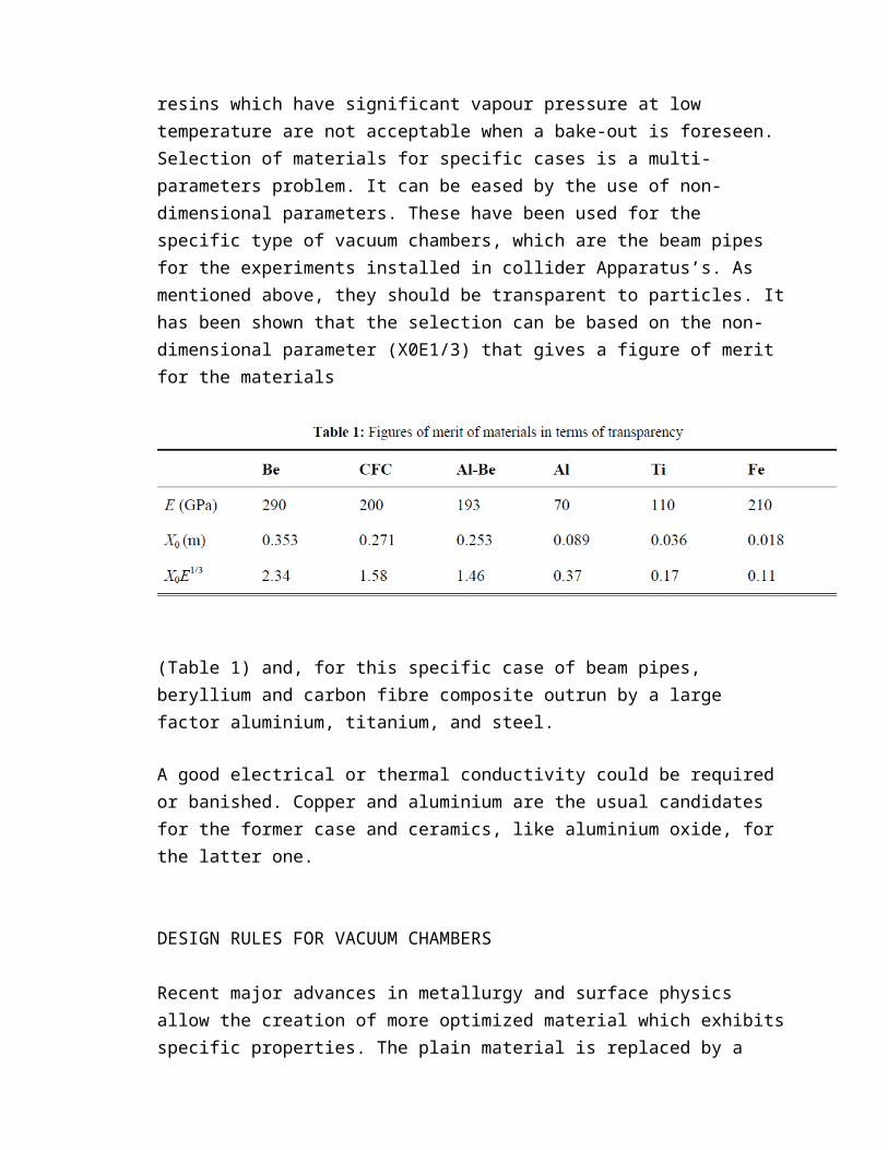
Selection of materials for specific cases is a multi-parameters problem. It can be eased by the use of non-dimensional parameters. These have been used for the specific type of vacuum chambers, which are the beam pipes for the experiments installed in collider Apparatus’s. As mentioned above, they should be transparent to particles. It has been shown that the selection can be based on the non-dimensional parameter (X0E1/3) that gives a figure of merit for the materials
(Table 1) and, for this specific case of beam pipes, beryllium and carbon fibre composite outrun by a large factor aluminium, titanium, and steel. A good electrical or thermal conductivity could be required or banished. Copper and aluminium are the usual candidates for the former case and ceramics, like aluminium oxide, for the latter one.
DESIGN RULES FOR VACUUM CHAMBERS
Recent major advances in metallurgy and surface physics allow the creation of more optimized material which exhibits specific properties. The plain material is replaced by a combination of materials, each with a specific function with a better physical parameter. Two examples among many combinations are the adjunction of a layer of a conductive material (copper) on a structural material (stainless steel) and, as a barrier to gas diffusion, a thin layer of aluminium on a structural material (carbon fibre composite).Besides the physical characteristics, specific technological properties should not be forgotten.Leak tightness of a vacuum chamber is a must but this may be difficult to obtain if the weldability of the material is poor and leads to the use of sophisticated and expensive techniques. Cost is the final criterion. Besides the material quality, in particular the cleanliness in terms of inclusions and impurities required and that one cannot necessarily afford on a large scale, the availability is a predominant factor. It is strongly recommended to favour materials of general use in industrial application.
Raw material is not the single parameter for the cost criterion since a complex and expensive manufacturing process could totally hamper the final cost. But machining could be efficient and fast and therefore cheap, although a large amount of costly raw material is lost as chips. Moreover the precision required for a welded part could need expensive tooling not included in the initial estimate. The most common materials are austenitic stainless steel (304,316LN, 316L, 304L), Aluminium alloys (5000 and 6000 series) and copper (OFHC, Glidcop).
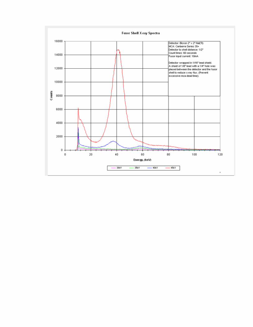
X RAY ATTENUATION CONSIDERATION
DATA FROM Jon Rosenstiel’s Reactor (highest neutron count achiever in Fusor.net)
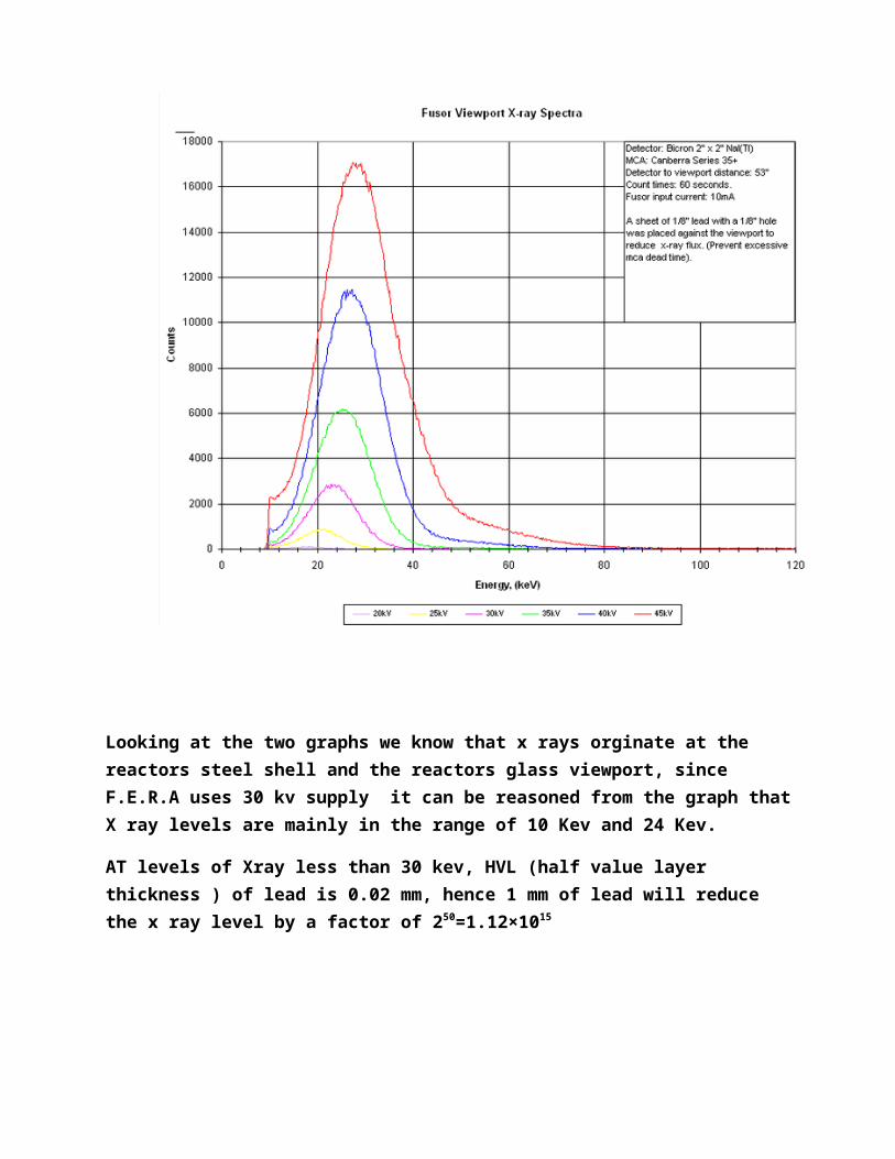
Looking at the two graphs we know that x rays orginate at the reactors steel shell and the reactors glass viewport, since F.E.R.A uses 30 kv supply it can be reasoned from the graph that X ray levels are mainly in the range of 10 Kev and 24 Kev.
AT levels of Xray less than 30 kev, HVL (half value layer thickness ) of lead is 0.02 mm, hence 1 mm of lead will reduce the x ray level by a factor of 250=1.12×10¹⁵
b) CALCULATION OF CHAMBER WALL TEMPERATURE
ASSUMPTION - Heat is generated at inner surface of spherical chamber due to electron bombardment.
- Chamber completely spherical.
- Heat is generated by 95 % of input power, hence 95% of input power is lost as heat.
GIVEN VALUES-
1) Our power supply is rated at 30KV @ 30 ma = 90 watts of input power.
2) Sphere radius = 4” = 101.6mm
CALCULATIONS
Input power = 30 KV * 30 ma=900watts
Power used up as heat = 95 % of 900 watts
= 0.95 × 900
= 810 watt
Inner surface area = 4×3.14× r2
= 4 × 3.14 ×0.1016 = 0.13067m2
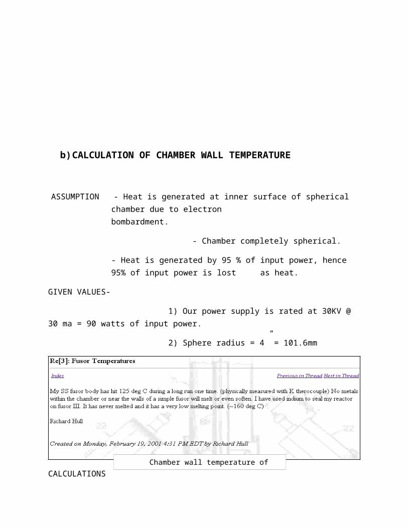
Chamber wall temperature of Richard Hull
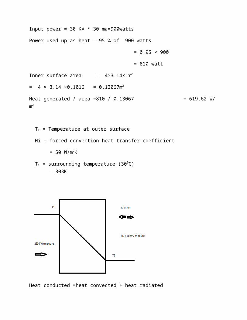
Heat generated / area =810 / 0.13067 = 619.62 W/ m2
T2 = Temperature at outer surface
Hi = forced convection heat transfer coefficient
= 50 W/m2K
T1 = surrounding temperature (300C) = 303K
Heat conducted =heat convected + heat radiated
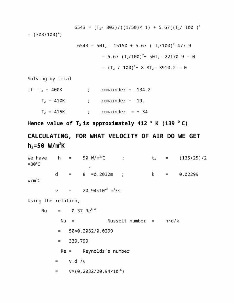
6543 = (T2- 303)/((1/50)× 1) + 5.67((T2/ 100 )4 - (303/100)4)
6543 = 50T2 – 15150 + 5.67 ( T2/100)2-477.9
= 5.67 (T2/100)2+ 50T2– 22170.9 = 0
= (T2 / 100)2+ 8.8T2– 3910.2 = 0
Solving by trial
If T2 = 400K ; remainder = -134.2
T2 = 410K ; remainder = -19.
T2 = 415K ; remainder = + 34
Hence value of T2 is approximately 412 o K (139 O C)
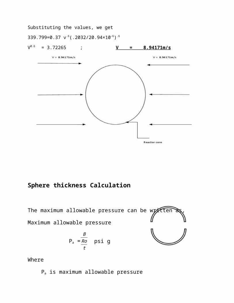
CALCULATING, FOR WHAT VELOCITY OF AIR DO WE GET hi=50 W/m2K
We have h = 50 W/m2oC ; tα = (135+25)/2 =80oC
d = 8” =0.2032m ; k = 0.02299 W/moC
ν = 20.94×10⁻⁶ m2/s
Using the relation,
Nu = 0.37 Re0.6
Nu = Nusselt number = h×d/k
= 50×0.2032/0.0299
= 339.799
Re = Reynolds’s number
= v.d /ν
= v×(0.2032/20.94×10-6)
Substituting the values, we get
339.799=0.37 v.6(.2032/20.94×10-6).6
V0.6 = 3.72265 ; V = 8.94171m/s
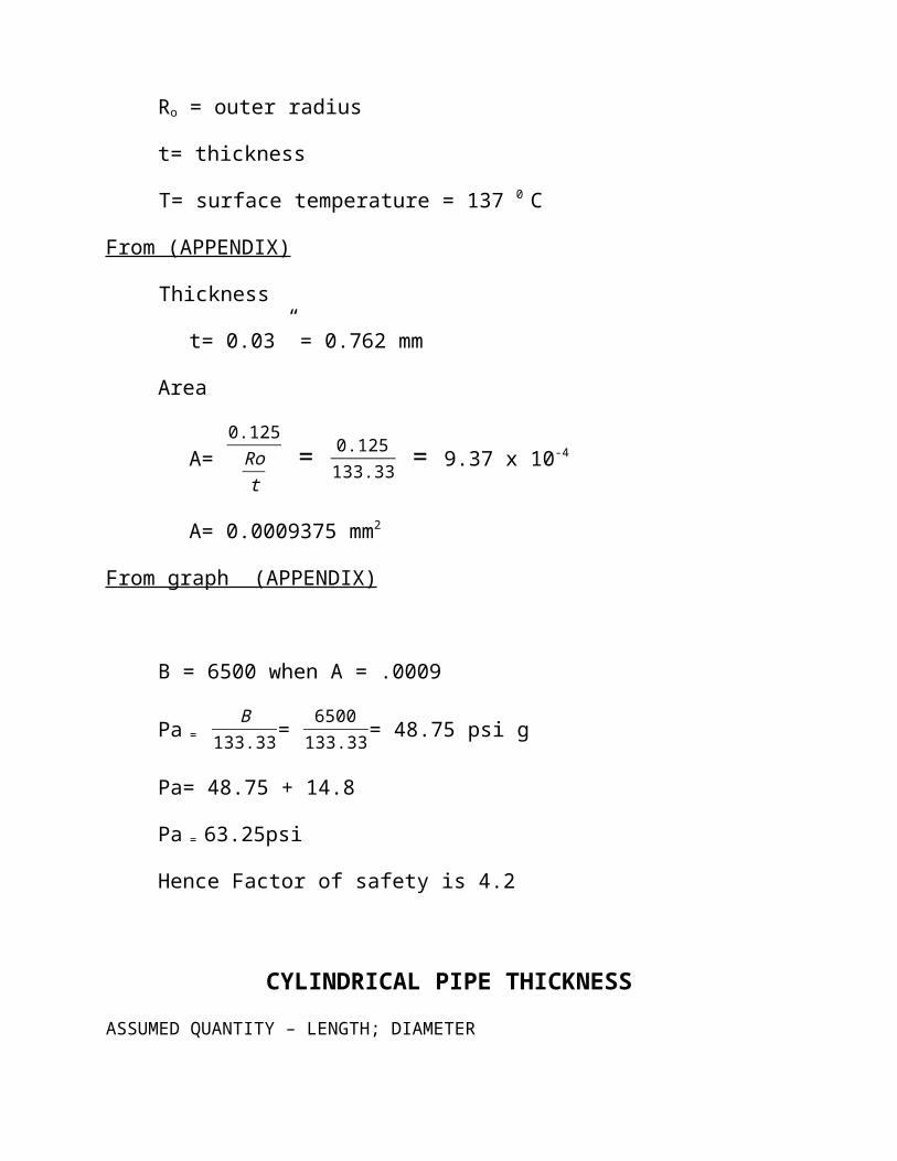
Sphere thickness Calculation
The maximum allowable pressure can be written as,
Maximum allowable pressure
Pa =BRot
psi g
Where
Pa is maximum allowable pressure
Ro = outer radius
t= thickness
T= surface temperature = 137 0 C
From (APPENDIX)
Thickness
t= 0.03” = 0.762 mm
Area
A= 0.125Rot
= 0.125133.33 = 9.37 x 10⁻⁴
A= 0.0009375 mm2
From graph (APPENDIX)
B = 6500 when A = .0009
Pa = B
133.33= 6500
133.33= 48.75 psi g
Pa= 48.75 + 14.8
Pa = 63.25psi
Hence Factor of safety is 4.2
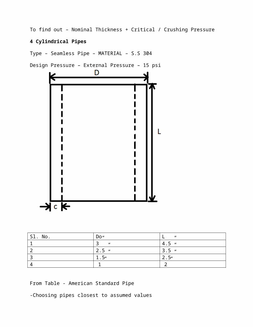
CYLINDRICAL PIPE THICKNESS
ASSUMED QUANTITY – LENGTH; DIAMETER
To find out – Nominal Thickness + Critical / Crushing Pressure
4 Cylindrical Pipes
Type – Seamless Pipe – MATERIAL – S.S 304
Design Pressure – External Pressure – 15 psi
Sl. No. Do L1 3” 4.5”2 2.5” 3.5”3 1.5” 2.5”4 1” 2”
From Table - American Standard Pipe
-Choosing pipes closest to assumed values
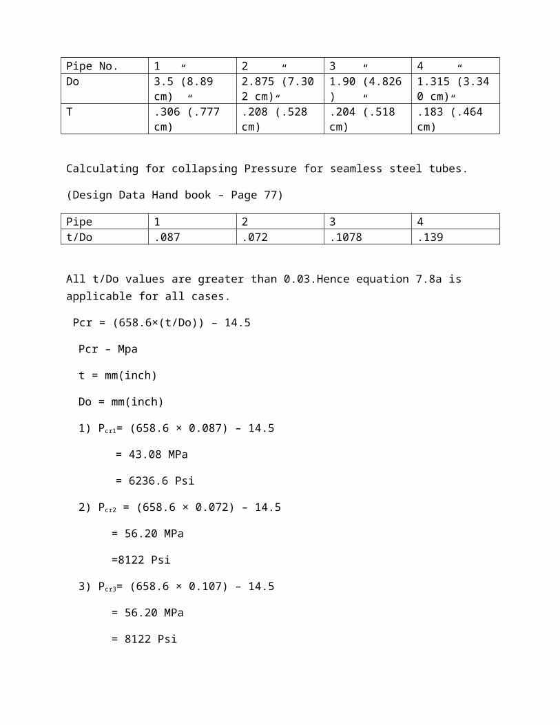
Pipe No. 1 2 3 4Do 3.5”(8.89 cm) 2.875”(7.302 cm) 1.90”(4.826) 1.315”(3.340 cm)T .306”(.777 cm) .208”(.528 cm) .204”(.518 cm) .183”(.464 cm)
Calculating for collapsing Pressure for seamless steel tubes.
(Design Data Hand book – Page 77)
Pipe 1 2 3 4t/Do .087 .072 .1078 .139
All t/Do values are greater than 0.03.Hence equation 7.8a is applicable for all cases.
Pcr = (658.6×(t/Do)) – 14.5
Pcr – Mpa
t = mm(inch)
Do = mm(inch)
1) Pcr1= (658.6 × 0.087) – 14.5
= 43.08 MPa
= 6236.6 Psi
2) Pcr2 = (658.6 × 0.072) – 14.5
= 56.20 MPa
=8122 Psi
3) Pcr3= (658.6 × 0.107) – 14.5
= 56.20 MPa
= 8122 Psi
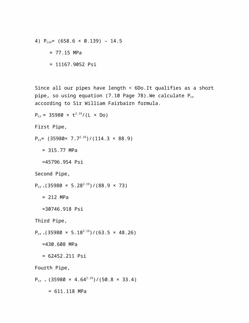
4) Pcr4= (658.6 × 0.139) – 14.5
= 77.15 MPa
= 11167.9052 Psi
Since all our pipes have length < 6Do.It qualifies as a short pipe, so using equation (7.10 Page 78).We calculate Pcr according to Sir William Fairbairn formula.
Pcr = 35980 × t2.19/(L × Do)
First Pipe,
Pcr= (35980× 7.72.19)/(114.3 × 88.9)
= 315.77 MPa
=45796.954 Psi
Second Pipe,
Pcr =(35980 × 5.282.19)/(88.9 × 73)
= 212 MPa
=30746.918 Psi
Third Pipe,
Pcr =(35980 × 5.182.19)/(63.5 × 48.26)
=430.608 MPa
= 62452.211 Psi
Fourth Pipe,
Pcr = (35980 × 4.642.19)/(50.8 × 33.4)
= 611.118 MPa
= 88632.052 Psi
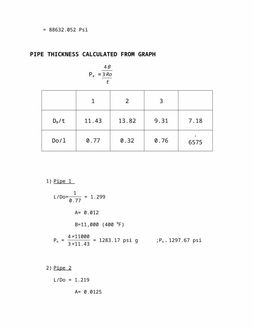
PIPE THICKNESS CALCULATED FROM GRAPH
Pa =4 B
3 Rot
1 2 3
D0/t 11.43 13.82 9.31 7.18
Do/l 0.77 0.32 0.76.
6575
1) Pipe 1
L/Do=1
0.77 = 1.299
A= 0.012
B=11,000 (400 0F)
Pa = 4×110003×11.43
= 1283.17 psi g ;Pa = 1297.67 psi
2) Pipe 2
L/Do = 1.219
A= 0.0125
B=11,000 (400 0F)
Pa = 4×110003×13.82
= 1061.2 psi g
Pa = 1297.67 psi
3) Pipe 3
L/Do= 1.315
A= 0.014
B=11,500 (400 0F)
Pa = 4×115003×9.31
= 1646.9 psi g
Pa = 1661.4 psi
4) Pipe 4
L/Do= 1.5209
A= 0.052
B=12,000 (400 0F)
Pa = 4×120003×7.18
= 2228.4 psi g
Pa = 2242 psi
ALL THE DETERMINED PIPE SIZES SATISFY DESIGN PRESSURE BY A LARGE VALUE
Design of flanges
PRESSURE CLASS
The Pressure Class or Rating for flanges will be given in pounds. Different names are used to indicate a
Pressure Class. For example: 150 Lb or 150 Lbs or 150# or Class 150, all are means the same.
Forged steel flanges are made in seven primary ratings:
150Lbs - 300Lbs - 400Lbs - 600Lbs - 900Lbs - 1500Lbs - 2500LbsThe concept of flange ratings likes clearly. A Class 300 flange can handle more pressure than a Class 150
flange, because a Class 300 flange are constructed with more metal and can withstand more pressure.
However, there are a number of factors that can impact the pressure capability of a flange.
EXAMPLE
Flanges can withstand different pressures at different temperatures. As temperature increases, the pressure
rating of the flange decreases. For example, a Class 150 flange is rated to approximately 270 PSIG at
ambient conditions, 180 PSIG at approximately 400°F, 150 PSIG at approximately 600°F, and 75 PSIG at
approximately 800°F. In other words, when the pressure goes down, the temperature goes up and vice
versa.
Additional factors are that flanges can be constructed from different materials, such as stainless steel, cast
and ductile iron, carbon steel et cetera. Each material have different pressure ratings.
PRESSURE-TEMPERATURE RATINGS
Pressure-temperature ratings are maximum allowable working gage pressures in bar units at the
temperatures in degrees celsius. For intermediate temperatures, linear interpolation is permitted.
Interpolation between class designations is not permitted.
Pressure-temperature ratings apply to flanged joints that conform to the limitations on bolting and on
gaskets, which are made up in accordance with good practice for alignment and assembly. Use of these
ratings for flanged joints not conforming to these limitations is the responsibility of the user.
The temperature shown for a corresponding pressure rating is the temperature of the pressure-containing
shell of the component. In general, this temperature is the same as that of the contained fluid. Use of a
pressure rating corresponding to a temperature other than that of the contained fluid is the responsibility
of the user, subject to the requirements of applicable codes and regulations. For any temperature below -
29°C, the rating shall be no greater than the rating shown for -29°C.
As an example, below you will find two tables with material groups acc. to ASTM, and two other tables
with flange pressure-temperature ratings for those ASTM materials acc. to ASME B16.5.
The above charts show the pressure in terms of bar
Our design pressure is 15 psi =1.034 bar at 139 O C
Design material is steel 18 Cr 8 Ni (304 type) which belongs to table2-2.3, hence the rated pressure according to above table is 12, 31.4, 41.9 so on……
Among these classes , class 150 satisfies our design pressure by a large margin hence we choose class 150 for all flange types
Rated pressure for class 150 at 150 o C is 12 bar that is 174 psi.
Design table of flanges inches (mm)
Pipe
Nom.
Pipe size
Outside
Dia Flange
Flange Thickness Drill Template
No Holes Diam Bolts Bolt Circle
1 1 (25.4) 4-1/4 (107.9) 9/16 (14.28 ) 4 ½ (12.7) 3-1/8 (79.3)
2 1-1/2 (38.1) 5 (127) 11/16 (17.46) 4 ½ (12.7) 3-7/8(98.4)
3 2-1/2 7 (177.8) 7/8 (22.22) 4 5/8 (15.87) 5-1/2 (138.7)
4 3-1/2 8-1/2(215.9) 15/16 (23.8) 8 5/8 (15.87) 7(177.8)
Calculating thickness of flanges using flat plate theory outlined in british pressure vessel code PD5500, (equation 8.6 design data book pg 87) that uses a simple formula:
Max allowable stress for 304 steel according to pressure vessel code is
16000psi
P =Design pressure is 15 psi
Assuming dia from above table and calculating “t”
Table for thickness of flange used with the four pipes
Pipe 1 flange Pipe 2 flange Pipe 3 flange Pipe 4 flange
“t” 1.38 mm 1.625 mm 2.27 mm 2.76 mm
DESIGN OF WELDED JOINTS
USE OF WELDED JOINTS
1. WELDED JOINTS ARE USED TO SEAL BOTH HEMISPHERES TO MAKE A COMPLETE SPHERE2. WELDED JOINTS ARE USED TO JOIN ALL PIPES TO HEMISPHERES3. WELDED JOINTS ARE USED JOIN THE PIPES TO FLANGES
METHOD OF WELDING USED IS TIG WELDING AS IT IS THE ONLY WELDING THAT PRODUCES VACUUM COMPATIBLE JOINTS( JOINTS WITH MINIMUM PORES)
TYPE OF JOINT USED TO JOINT 1 IS GROOVE WELD
TYPE OF JOINT FOR 2 AND 3 IS FILLET WELD
SOURCE: http://www.welding-technology-machines.info/welding-design/stress-allowable-for-weld-metal.htm
WELD CALCULATIONS
O RING DESIGN
O-ring and Seal Design Theory
The use of an o-ring as a seal is mainly to prevent the transfer of fluid (liquid, solid or gas) between two or more regions. The components of the seal are the o-ring itself and the contact surfaces. The elastomeric o-ring relies on a compressive force acting on the o-ring to prevent the transfer of fluid between regions. Successful seal design ensures adequate seal compressive force while optimizing the destructive stress acting on the o-ring as a result of the compression or of the environment.
Three Models for Characterizing Viscoelastic Behavior Are:
1. Maxwell Model (dashpot and spring in series)
2. Kelvin (Voigt) Model (dashpot and spring in parallel)
3. Standard Linear Solid (dashpot and spring in series with a spring in parallel).*
Three Considerations
Incompressibility
A material is incompressible if it exhibits zero volumetric change (isochoric) under hydrostatic pressure. Theoretically, Poisson's ratio is exactly one-half (0.5) and the bulk modulus is infinite (and det f = 1).
Near incompressibility means that Poisson's ratio is slightly less than 0.5.
Viscoelasticity
Rubber exhibits a rate-dependent behavior that can be modeled as a viscoelastic material whose properties change with temperature and time. Features of viscoelastic materials are:
Under constant stress leads to creep Under constant strain leads to stress relaxation During loading/unloading leads to hysteresis
1. Internal friction-rearrangement of molecular structure under load.
2. Strain-induced crystallization-formation and melting of crystallized regions.
3. Stress softening (Mullin's effect).
4. Structural breakdown-the breakdown of reinforcing filler/ polymer bonds.
5. Domain deformation-dispersed inclusions contribute to hysteresis.
Thermomechanical
Temperature change causes thermal strains. Material properties change. Heat flow may occur.
Outgassing Rates of Elastomers and Various Materials
MaterialRATE*
(10-9 mbar/sec-cm2)
RATE**(10-8 Torr-liter/sec)
Stainless Steel 13.5
Steel, Chrome Plated 7.1
Stainless Steel,Electropolished
4.3
Aluminum 6.3
Nitrile 3,500 300
KEL-F 40 4
Silicone 18,000 2,000
Fluoroelastomer 1,140 2,000
Fluoroelastomer, baked 4 0.2
Perfluoroelastomer 0.3
PTFE 300 400
Polyimide 900 80
Pyrex glass 7.4
Static Glands - Axial (Face Seal)
O-Ring Size O-Ring Gland Actual % Groove Width Groove
Cross Section Depth Squeeze Squeeze Liquids Gas/Vacuum Radius
004 to 050 .070" +/-.003 .050 to .054 .013 to .023 19 to 32 .101 to .107 .084 to .089 .005 to .015
102 to 178 .103" +/-.003 .074 to .080 .020 to .032 20 to 30 .136 to .142 .120 to .125 .005 to .015
201 to 284 .139" +/-.004 .101 to .107 .028 to .042 20 to 30 .177 to .187 .158 to .164 .010 to .025
309 to 395 .210" +/-.005 .152 to .162 .043 to .063 21 to 30 .270 to .290 .239 to .244 .020 to .035
410 to 475 .275" +/-.006 .201 to .211 .058 to .080 21 to 29 .342 to .362 .309 to .314 .020 to .035
Note: The above chart and information is intended for reference use only. Gland design has many variables to consider such as temperature, pressure, range, performance requirements..
WARNING:Gland Depth x Groove Width (area of the gland)must be larger than the cross section area of the o-ring. Otherwise many bad things will happen to your design.
APPROACH TO OUR PROJECT
Our project is essentially a collection of experiments. And these experiments are divided into three main Phases.
1 st : This phase consists of designing, machining and testing our vacuum chamber for UHV conditions.
There would be two vacuum chambers to be built Chamber A: a pressure cooker chamber capable of doing fusion.
Also there would be a Chamber B: Built to professional standards with proper ports and also capable of withstanding Fusion conditions.
In the first phase we will have our first test of our chambers and hence conduct our first vacuum sealing attempt, subsequent attempts will hence be done till we get vacuum of 1 micron.
This phase will be completed in the Seventh semester.
2 nd : This phase will consist of construction of our power supply.
I. Our target is reaching 30000volts at 30ma for a time of 45 mins
II. Having a voltage measuring setup and a current measuring setup
III. Having two ground connections IV. Isolating our power grid from mains magnetically.
We will be using plan, a) NEON transformer and increase voltage using a voltage multiplier.
b) X-ray transformers rated at 100 kv, so that it can be used at 40 kv continuously.
c) Create a cascade of Flyback transformer ( TV SETS), or auto ignition transformer (cars).
d) Create a cascade of Microwave transformers.
This phase is to be completed in the first two months of our 8 th semester.
3rd : this phase consists of the final Fusion experiment.
This phase requires us to have
I. Shielding for radiation (lead)II. Shielding for x-rays( stainless steel)
III. Neutron detection equipment( dosimeter, cloud chamber etc)IV. Safety guide to verify our results.V. Finally compiling our data and presenting it to a panel of experts.
PHASE 1
AIM:
TO DESIGN A FEASIBLE VACUUM CHAMBER AND TO SIMULATE THE STRESSES INVOLVED IN THE DESIGN USING ANALYSIS SOFTWARES
TO DESIGN THE MACHINING PROCEDURE FOR SUCH A CHAMBER, AND HENCE MACHINE IT TO THE DESIGN SPECS
TO TEST OUR VACUUM CHAMBER. (AND POSSIBLY CERTIFY ITS SAFETY) TO MAKE A SECONDARY CHAMBER OUT OF A PRESSURE COOKER
Requirements: An extensive knowledge of reactor design principles, and also Ansys.
Possible chamber material study and their availability in India.
Research on various kinds of Seals available in market their operating range and feasibility.
Study on valves and vacuum pumps.
Study on pressure cookers
Vacuum sealing fluids to fix leaks.
To design an operating procedure.
To design emergency guidelines.
PERIOD OF COMPLETION:
AUGUST- NOVBEMBER;
DEADLINE-NOVEMBER 1ST WEEK.
EXPENDITURE INVOLVED : To be calculated
PHASE 2
AIM:
TO DESIGN A POWER SUPPLY CAPABLE OF SUPPLYING THE FUSION POWER TO PROVIDE NECESSARY EARTHING TO OUR EQUIPMENT TO DESIGN OUR WORK ENVIRONMENT WITH A STABLE STAND AND PROPPER
DISTANCES MAINTAINED WITH HIGH VOLTAGE SOURCES TO PRODUCE PLASMA ON A DRY RUN TO VERIFY OUR RESULTS
REQUIREMENTS:
Knowledge on fields such as High voltage transformers,
Rectification schemes
Voltage multipliers
High voltage safety
Plasma physics
PERIOD OF COMPLETION: undecided
PHASE 3
AIM:
TO DESIGN OUR FUEL SUPPLY TO CALCULATE ITS SPECS TO PRODUCE FUSION TO DETECT NEUTRONS
REQIREMENTS:
SAFETY CLEARANCES
GOVERNMENT ACKNOWLWDGEMENT
NEUTRON DETECTION EQUIPMENT
PERIOD OF COMPLETION: UNCERTAIN
CONCLUSION
If we could design our future what would it be like?...should we have places where petrol costs more than beer? Over polluted cities? Constant black outs?
If you’ve seen sci-fi novels or movies, a common idea of future is a place with flying cars, spaceships, lightsabres, and pollution free land.
Our thirst for energy will keep growing as we go into our future. It has been predicted that in the next five years we will have a major energy crisis, as we become more technologically advanced we require more power.
Nuclear fusion fits all criteria as our future energy source.It is cheap, much simpler and cleaner, pollution free has no hazardous wastes and has a very little chance of failure. If I.E.C devices are successful, they would not only replace power plants but also commercial engines. They would aid in de-centralization of power, and enable space travel, with technology our fuel can be universes most common element.
BIBLIOGRAPHY
• ‘Notes Of Richard Hull’
• Tom Ligon’s article –Worlds simplest fusion reactor
-Fusor tips
• Amateur Nuclear Fusion- Raymond Jimenez
• Fusion Pamphlet- Raymond Jimenez
• RTF technologies
• en.wikipedia.org/wiki/Nuclear_fusion
• en.wikipedia.org/wiki/Fusion_power
• en.wikipedia.org/wiki/Cold_fusion
• www.atomicarchive.com › Science
• hyperphysics.phy-astr.gsu.edu/hbase/nucene/fusion.html
• http://www.bisbos.com/rocketscience/spacecraft/bussardramjet/bussard.html
• www.Fusor.com/formums
• Tidbit77.blogspot.com
• www.instructables.com