ing. giovanni conticello ing. sebastiano floridia · corso umberto i, 39 96100 siracusa-italy user...
TRANSCRIPT

Corso Umberto I, 39 96100 Siracusa-Italy
www.progettoarchimede.it
U s e r M a n u a l – V e r s i o n 1 . 1 1 . 0 . 5 9 - J a n u a r y 2 3 2 0 1 4 P a g e 1 of 354
Ing. Giovanni Conticello Ing. Sebastiano Floridia
With the important help of
Ing. Giovanni Trigili
JointsForTekla
Ver. 1.11.0.59 - January 23 2014
Design of joints of steel structures
in environment TeklaStructures 19.0
Corso Umberto I, 39 96100 Siracusa-Italy
www.progettoarchimede.it
U s e r M a n u a l – V e r s i o n 1 . 1 1 . 0 . 5 9 - J a n u a r y 2 3 2 0 1 4 P a g e 2 of 354
JointsForTekla
1 INTRODUCTION
1.1 All you necessarily need know before starting
- The software JointForTekla designs the following kind of joints: 141, 142, 143, 144, 42, 77, 14,11, 124, 128, 40, 1014, 1052;
- TeklaStructures has got infinity potentialities of joints modeling so it’s impossible that a controller can consider every estimated possibility.
- JointForTekla has been positively tested about structures with real joints but it
hasn’t got tested about joints torn off by real design.
2 DIRECTIONS
2.1 Characteristics of the Software
JointForTekla (JFT) is a software to design steel structures with steel joints in according with Eurocode 3 in environment TeklaStructures 19.0 .
This software is closely linked with TeklaStructures. Without it the software cannot work and it works using every tridimensional modeling potentiality, get up every information about joints by Teklastructures and can use them for joint numerical code
selected in according with EC3 and following report results.
Among the most important JointForTekla potentialities we note:
• Immediate data input, by TeklaStructures data ; • Possibility to get up by data file exterior the values of infinity loading combinations; • Possibility to get up the data by structural MidasGen model;
2.2 Minimum qualification hardware and software
• Any for working with TeklaStructures; • Framework 4.0
The Windows Panel control with International format, must be plan out so that the
system know it: • the point like decimal separator;
• the colon like thousands separator.
Corso Umberto I, 39 96100 Siracusa-Italy
www.progettoarchimede.it
U s e r M a n u a l – V e r s i o n 1 . 1 1 . 0 . 5 9 - J a n u a r y 2 3 2 0 1 4 P a g e 3 of 354
2.3 Conventions
The units are: • for length the centimetre; • for loadings: the KiloNewton (KN), corresponding to 101.9 kg for forces;
• for loadings: the KiloNewton (KN*m), for static moment; • for model get up from MidasGen the units will be N and mm;
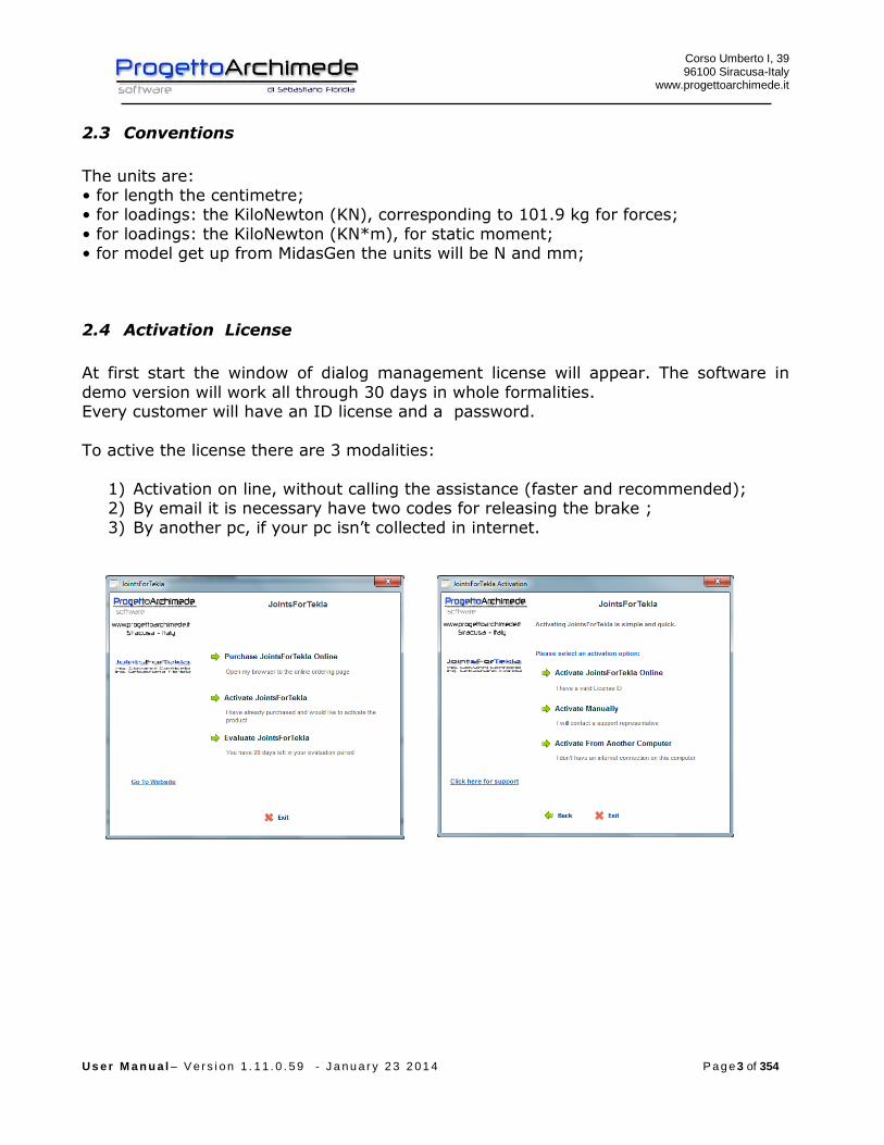
2.4 Activation License
At first start the window of dialog management license will appear. The software in
demo version will work all through 30 days in whole formalities. Every customer will have an ID license and a password.
To active the license there are 3 modalities:
1) Activation on line, without calling the assistance (faster and recommended); 2) By email it is necessary have two codes for releasing the brake ;
3) By another pc, if your pc isn’t collected in internet.
Corso Umberto I, 39 96100 Siracusa-Italy
www.progettoarchimede.it
U s e r M a n u a l – V e r s i o n 1 . 1 1 . 0 . 5 9 - J a n u a r y 2 3 2 0 1 4 P a g e 4 of 354
2.5 Off License
When you want to install your license in another pc, you can use the command
“removing license”. So you can active your license in another pc and viceversa, whenever you want.
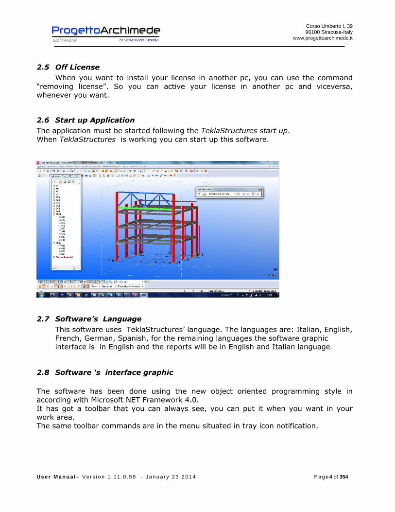
2.6 Start up Application
The application must be started following the TeklaStructures start up.
When TeklaStructures is working you can start up this software.
2.7 Software’s Language
This software uses TeklaStructures’ language. The languages are: Italian, English,
French, German, Spanish, for the remaining languages the software graphic interface is in English and the reports will be in English and Italian language.
2.8 Software ‘s interface graphic
The software has been done using the new object oriented programming style in according with Microsoft NET Framework 4.0.
It has got a toolbar that you can always see, you can put it when you want in your work area.
The same toolbar commands are in the menu situated in tray icon notification.
Corso Umberto I, 39 96100 Siracusa-Italy
www.progettoarchimede.it
U s e r M a n u a l – V e r s i o n 1 . 1 1 . 0 . 5 9 - J a n u a r y 2 3 2 0 1 4 P a g e 5 of 354
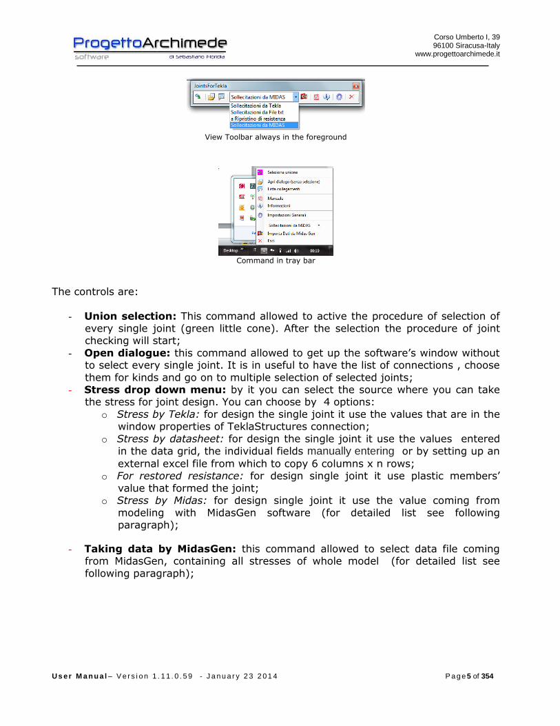
View Toolbar always in the foreground
Command in tray bar
The controls are:
- Union selection: This command allowed to active the procedure of selection of every single joint (green little cone). After the selection the procedure of joint checking will start;
- Open dialogue: this command allowed to get up the software’s window without to select every single joint. It is in useful to have the list of connections , choose
them for kinds and go on to multiple selection of selected joints; - Stress drop down menu: by it you can select the source where you can take
the stress for joint design. You can choose by 4 options:
o Stress by Tekla: for design the single joint it use the values that are in the window properties of TeklaStructures connection;
o Stress by datasheet: for design the single joint it use the values entered
in the data grid, the individual fields manually entering or by setting up an
external excel file from which to copy 6 columns x n rows;
o For restored resistance: for design single joint it use plastic members’
value that formed the joint;
o Stress by Midas: for design single joint it use the value coming from
modeling with MidasGen software (for detailed list see following paragraph);
- Taking data by MidasGen: this command allowed to select data file coming from MidasGen, containing all stresses of whole model (for detailed list see
following paragraph);

Corso Umberto I, 39 96100 Siracusa-Italy
www.progettoarchimede.it
U s e r M a n u a l – V e r s i o n 1 . 1 1 . 0 . 5 9 - J a n u a r y 2 3 2 0 1 4 P a g e 6 of 354
- Manual: From this command you can enter in Pdf manual;
- Information from this window it is possible to enter in the software general information

Corso Umberto I, 39 96100 Siracusa-Italy
www.progettoarchimede.it
U s e r M a n u a l – V e r s i o n 1 . 1 1 . 0 . 5 9 - J a n u a r y 2 3 2 0 1 4 P a g e 7 of 354
- General planning out: From this window it is possible to enter in the software’s
general planning out: o Normative: You can choose between EC3 and DM2008 for the definition of
general partial factor value M1;
o Concrete type(cls): you can define the concrete with which did the foundation (it is necessary for design joints 1014 and 1052);
o Concrete edge distance: the value of distance between anchor bolts and external foundation edge is in mm (it is necessary for anchor bolts design joints 1014 e 1052);
o The software has got a connection at the server www.progettoarchimede.it so you can always have the up to date software. The procedure can be
done manually and outside from software, by special icon in operative system in the joint group or automatically at each software startup, if there is an active internet connection;
o Radius zoom in the joint: This value allowed to adjust zoom factor in the click of joints in the model;
o Zoom at treeview joint: this value allowed qualifying or not qualifying the possibility to take place the zoom over the joint in the model;
o Default Value (if the materiali is unknow). In this pane are inserted the
resistance values of the materials in case the material set is not present in the database of JointsForTekla;
o Default Value (if the Botls are unknow). In this pane are inserted the
resistance values of the bolts, in the case where the class of bolts set is not present in the database of JointsForTekla.
- Esc: This command allowed exit the application.
Corso Umberto I, 39 96100 Siracusa-Italy
www.progettoarchimede.it
U s e r M a n u a l – V e r s i o n 1 . 1 1 . 0 . 5 9 - J a n u a r y 2 3 2 0 1 4 P a g e 8 of 354
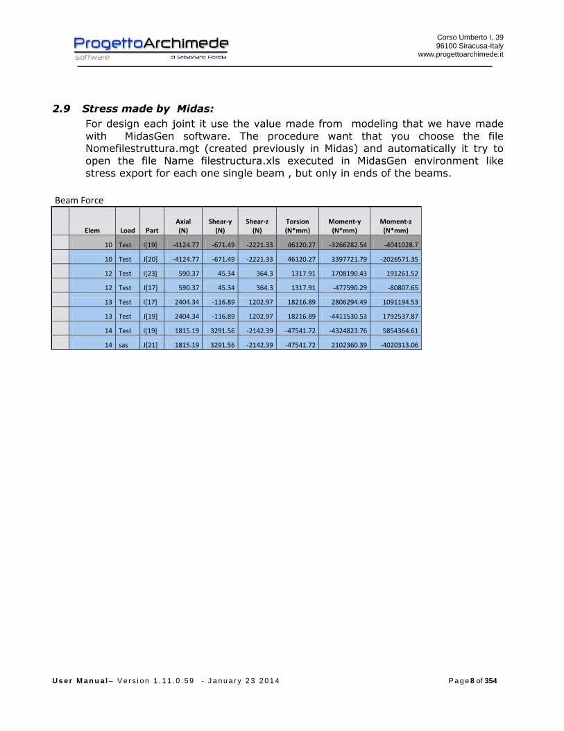
2.9 Stress made by Midas:
For design each joint it use the value made from modeling that we have made
with MidasGen software. The procedure want that you choose the file Nomefilestruttura.mgt (created previously in Midas) and automatically it try to open the file Name filestructura.xls executed in MidasGen environment like
stress export for each one single beam , but only in ends of the beams.
Beam Force
Elem Load Part Axial (N)
Shear-y (N)
Shear-z (N)
Torsion (N*mm)
Moment-y (N*mm)
Moment-z (N*mm)
10 Test I[19] -4124.77 -671.49 -2221.33 46120.27 -3266282.54 -4041028.7
10 Test J[20] -4124.77 -671.49 -2221.33 46120.27 3397721.79 -2026571.35
12 Test I[23] 590.37 45.34 364.3 1317.91 1708190.43 191261.52
12 Test J[17] 590.37 45.34 364.3 1317.91 -477590.29 -80807.65
13 Test I[17] 2404.34 -116.89 1202.97 18216.89 2806294.49 1091194.53
13 Test J[19] 2404.34 -116.89 1202.97 18216.89 -4411530.53 1792537.87
14 Test I[19] 1815.19 3291.56 -2142.39 -47541.72 -4324823.76 5854364.61
14 sas J[21] 1815.19 3291.56 -2142.39 -47541.72 2102360.39 -4020313.06
Corso Umberto I, 39 96100 Siracusa-Italy
www.progettoarchimede.it
U s e r M a n u a l – V e r s i o n 1 . 1 1 . 0 . 5 9 - J a n u a r y 2 3 2 0 1 4 P a g e 9 of 354
3 CONNECTIONS – THEORY AND METHOD
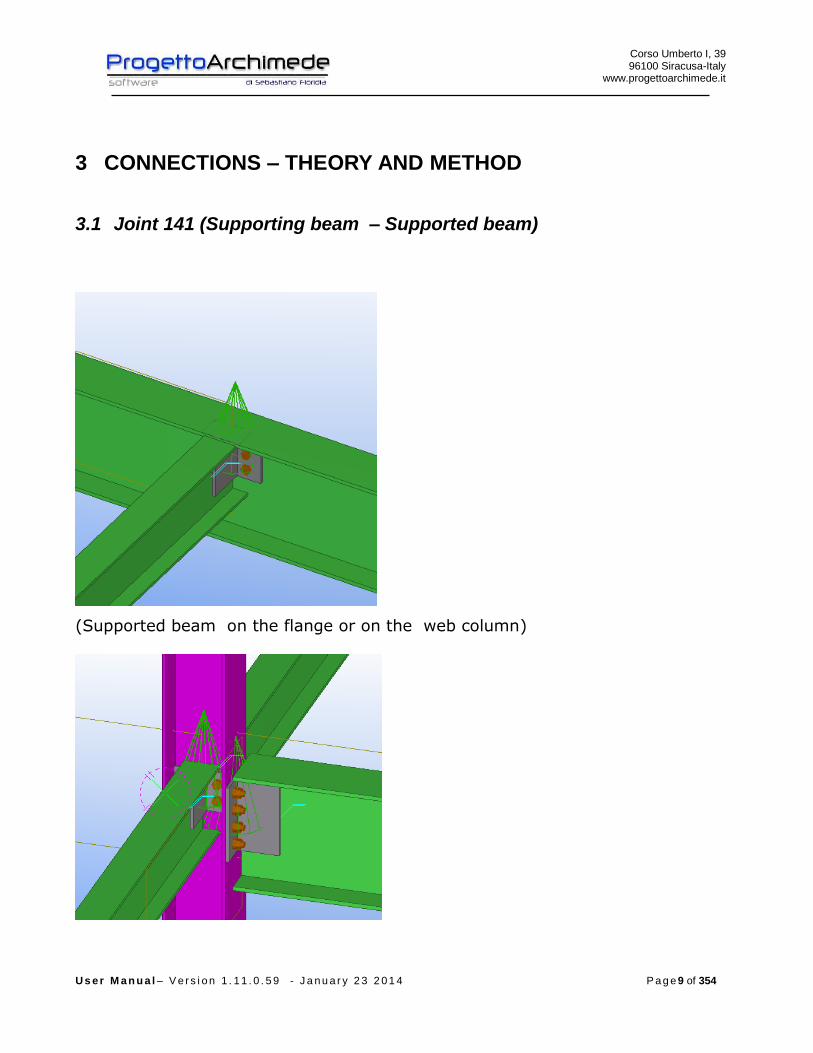
3.1 Joint 141 (Supporting beam – Supported beam)
(Supported beam on the flange or on the web column)
Corso Umberto I, 39 96100 Siracusa-Italy
www.progettoarchimede.it
U s e r M a n u a l – V e r s i o n 1 . 1 1 . 0 . 5 9 - J a n u a r y 2 3 2 0 1 4 P a g e 10 of 354
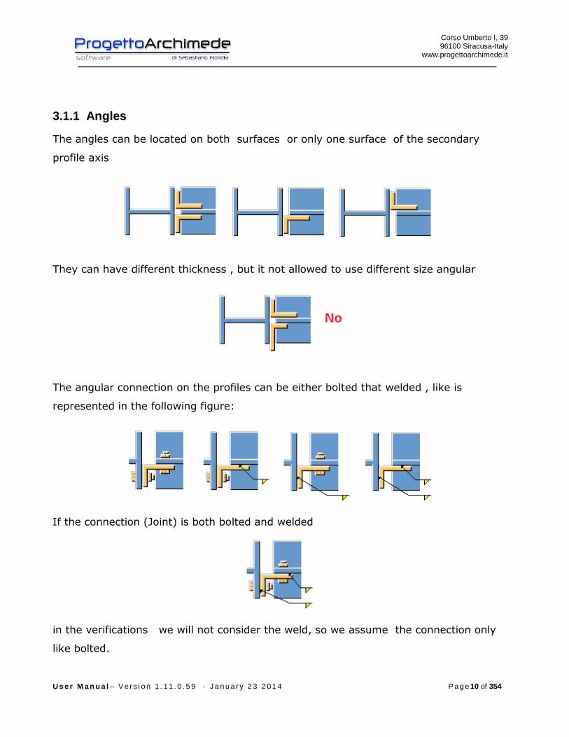
3.1.1 Angles
The angles can be located on both surfaces or only one surface of the secondary
profile axis
They can have different thickness , but it not allowed to use different size angular
The angular connection on the profiles can be either bolted that welded , like is
represented in the following figure:
If the connection (Joint) is both bolted and welded
in the verifications we will not consider the weld, so we assume the connection only
like bolted.

Corso Umberto I, 39 96100 Siracusa-Italy
www.progettoarchimede.it
U s e r M a n u a l – V e r s i o n 1 . 1 1 . 0 . 5 9 - J a n u a r y 2 3 2 0 1 4 P a g e 11 of 354
3.1.2 Forces
On the secondary profile we can apply the following forces:
EdN axial force (positive if tensile)
xEdV , horizontal plane shear force
yEdV , vertical plane shear force
The forces may be inserted by Tekla Structures (except xEdV , ), by modeler Midas, by
text file or we can calculate the structure to restore strength.
If the stresses from Tekla Structures are zero, the forces will have minimum value
according with EC3 1-8 point 6.2.7.1.(13)
plEd NN 025.0
plyEd VV 025.0,
where the plastic resistances are referred at the secondary profile .
The joint is schematized as hinged joint, because it is generally used as end joint.
Corso Umberto I, 39 96100 Siracusa-Italy
www.progettoarchimede.it
U s e r M a n u a l – V e r s i o n 1 . 1 1 . 0 . 5 9 - J a n u a r y 2 3 2 0 1 4 P a g e 12 of 354
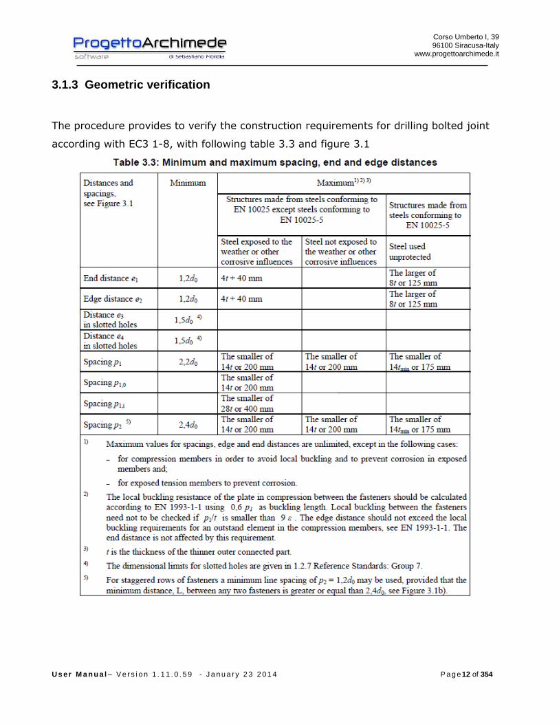
3.1.3 Geometric verification
The procedure provides to verify the construction requirements for drilling bolted joint
according with EC3 1-8, with following table 3.3 and figure 3.1

Corso Umberto I, 39 96100 Siracusa-Italy
www.progettoarchimede.it
U s e r M a n u a l – V e r s i o n 1 . 1 1 . 0 . 5 9 - J a n u a r y 2 3 2 0 1 4 P a g e 13 of 354
3.1.4 Design resistance of single bolt and single weld
In this section we recall the common criteria for verification of single bolts and single
weld.

Corso Umberto I, 39 96100 Siracusa-Italy
www.progettoarchimede.it
U s e r M a n u a l – V e r s i o n 1 . 1 1 . 0 . 5 9 - J a n u a r y 2 3 2 0 1 4 P a g e 14 of 354
3.1.4.1 Design resistance at bolt’s tension force
Single bolt tension resistance is:
2,
9.0
M
subRdt
AfF
where
sA is the tensile stressed area
ubf is the last tensile bolt strength
3.1.4.2 Bolt shear force resistance design
For a shear connection (see class A EC3 1-8 point 3.4.1) the single bolt shear force
design (for a single resistant section) is:
2
,,M
ubvRdv
AfF
If the shear force plane is through the threated bolt portion:
- for classes 4.6, 5.6 and 8.8
6.0v
- for classes 4.8, 5.8 and 10.9
5.0v
If the shear force plane is through not threaded bolt portion:
6.0v
While
A is bolt area
ubf is the last bolt tension
3.1.4.3 Design resistance of weld
Fillet weld design resistance is:
lafF dvwRdw .,
Where
dvwf . is the welding shear design resistance.

Corso Umberto I, 39 96100 Siracusa-Italy
www.progettoarchimede.it
U s e r M a n u a l – V e r s i o n 1 . 1 1 . 0 . 5 9 - J a n u a r y 2 3 2 0 1 4 P a g e 15 of 354
a is throat weld height.
l is cordon weld length.
The welding shear resistance calculation is:
2.
3/
Mw
udvw
ff
where:
uf is the nominal resistance breaking of weaker joint;
w is the appropriate correlation factor shown in table 4.1.
3.1.5 Annotations
In the verifications the sizes regarding supported beam will have the wb pedice and
regarding supporting beam the pedice wc.
3.1.6 Verifications made
Verifications made on the joint are the following:

Corso Umberto I, 39 96100 Siracusa-Italy
www.progettoarchimede.it
U s e r M a n u a l – V e r s i o n 1 . 1 1 . 0 . 5 9 - J a n u a r y 2 3 2 0 1 4 P a g e 16 of 354
- Bolt’s shear force on the supported beam
RdvEdv FF ,,
- Weld on the supported and supporting beam
RdwEdw FF ,,
- Shear and tension force bolt on the supporting beam
tensionandshear of caseIn 4.1//
ononly tensi of caseIn
shearonly of caseIn
,,,,
,,
,,
RdtEdtRdvEdv
RdtEdt
RdvEdv
FFFF
FF
FF
- Net and gross sections profile and angular verification on supported and
supporting beam due to stress tensile and shear force
Rdu
RdplEd N
NN
,
,
Rdu
RdplEd V
VV
,
,
- Verification for profiles and angles Block Tearing on the supported and
supporting beam, due to tensile and shear force
effEd NN
effEd VV
- Verification bearing resistance on two directions, horizontal and vertical profiles
and angular on supported an supporting beam
RdbEdb FF ,,

Corso Umberto I, 39 96100 Siracusa-Italy
www.progettoarchimede.it
U s e r M a n u a l – V e r s i o n 1 . 1 1 . 0 . 5 9 - J a n u a r y 2 3 2 0 1 4 P a g e 17 of 354
3.1.7 Shear force bolt verification (supported beam)
The verification is made considering together normal stress and shear force acting on
supported beam.
If we consider a reference system x-y on the supported beam plan, with x coincident
with beam axis, , y orthogonal to the beam axis and the origin coincident with bolt
barycenter, for equilibrium to the translation and rotation relative the supporting beam
axis, the loads in the barycenter of group bolts on the bracket are :
eVT
VV
NV
yEd
yEdy
Edx
,
Where
e is the distance between the barycenter of the group bolts and the supporting axis
beam, while EdT is the parasite torsion due to eccentricity.
The single bolt shear actions, for single bolt shear plan are :
ibv
EdEdEdy
ibv
EdEdEdx
bv
yyEdy
bv
xxEdx
xJn
TTV
yJn
TTV
nn
VVV
nn
VVV
)(
)(
)(
)(
,
,
,
,
With
)( 22 ynxnJ bh
i
bvb bolt’s polar moment
bn total number bolts
vn number shear resistant bolt sections
bhn number bolts for line
bvn number bolts for row

Corso Umberto I, 39 96100 Siracusa-Italy
www.progettoarchimede.it
U s e r M a n u a l – V e r s i o n 1 . 1 1 . 0 . 5 9 - J a n u a r y 2 3 2 0 1 4 P a g e 18 of 354
ix single bolt distance from the barycenter of the group bolts, in the verification we consider
maxx
iy single bolt distance from the barycenter of the group bolts, in the verification we consider
maxy
The resultant of the forces on single bolt for single bolt shear plan is:
2,,
2,,, ))()(())()(( EdEdyyEdyEdEdxxEdxEdv TVVVTVVVF
Must satisfy:
RdvEdv FF ,,
3.1.8 Weld verification (supported beam)
Verification is done considering together orthogonal force and shear acting on the
supported beam.
If we consider a reference system x-y on supported beam plan, with x coincident with
beam axis , y orthogonal beam axis and the origin in vertical cordon barycenter, for
equilibrium to vertical translation and rotation relative to supporting beam axis, for
each angle must be two horizontal welding (one superior and one inferior) and one
vertical welding on supported beam.
The forces on the bracket are :
eVT
VV
NV
yEd
yEdy
Edx
,
Where
e is the distance between vertical welding barycenter and supporting beam axis, while
EdT is the parasite torsion due to eccentricity.
The horizontal and vertical actions on welds are :

Corso Umberto I, 39 96100 Siracusa-Italy
www.progettoarchimede.it
U s e r M a n u a l – V e r s i o n 1 . 1 1 . 0 . 5 9 - J a n u a r y 2 3 2 0 1 4 P a g e 19 of 354
)(
)(2
)(
,
,
,
hangles
EdEdEdx
yyEdy
xxEdx
h
TTV
VVV
VVV
with
hanglesh angle height
Force resultant on horizontal welding is :
)()(( ,,,, EdEdxxEdxEdxw TVVVF
Force resultant on vertical welding is:
)(,,, yEdyEdyw VVF
Must satisfy:
RdwEdw FF ,,
with
lafF dvwRdw ., one angle
2., lafF dvwRdw two angles
where
l is single cordon length
a is throat height.
3.1.9 Shear and tension force bolt verification (supporting beam)
The verification is made considering together normal stress and shear acting on
supported beam.
If we consider a reference system x-y on supporting beam’s plan, with axis x
coincident with beam’s axis, axis y orthogonal to beam’s axis and origin in the bolt’ s
Corso Umberto I, 39 96100 Siracusa-Italy
www.progettoarchimede.it
U s e r M a n u a l – V e r s i o n 1 . 1 1 . 0 . 5 9 - J a n u a r y 2 3 2 0 1 4 P a g e 20 of 354
barycenter that are on one angular, for vertical translation and rotation equilibrium
relative to the supported beam axis, shear force solicitations in the group bolt’s
barycenter on single bracket are:
eVT
VV
VV
yEd
yEdy
xEdx
2/
2/
,
,
If on supporting beam is only one angular the stresses on the group bolts’ barycenter
on bracket are:
eVT
VV
VV
yEd
yEdy
xEdx
,
,
Where
e is the distance between the barycenter of group bolts of single angular and
supported beam’s axis, while EdT is the parasite torsion due to eccentricity.
The force shear of single bolt for single bolt shear plan are:
ibv
EdEdEdy
ibv
EdEdEdx
bv
yyEdy
bv
xxEdx
xJn
TTV
yJn
TTV
nn
VVV
nn
VVV
)(
)(
)(
)(
,
,
,
,
With
)( 22 ynxnJ bh
i
bvb bolts polar moment
bn bolts total number
vn bolt number sections shear resistant
bhn bolts number per horizontal row
bvn bolts number per vertical row

Corso Umberto I, 39 96100 Siracusa-Italy
www.progettoarchimede.it
U s e r M a n u a l – V e r s i o n 1 . 1 1 . 0 . 5 9 - J a n u a r y 2 3 2 0 1 4 P a g e 21 of 354
ix single bolt distance from barycenter of group bolts, in verification we consider maxx
iy single bolt distance from barycenter of group bolts, in verification we consider maxy
The forces resultant on single bolt for single bolt shear plan is:
2,,
2,,, ))()(())()(( EdEdyyEdyEdEdxxEdxEdv TVVVTVVVF
The tension force on single bolt belonging to the group of bolts of a bracket is:
bEdt nNF /,
That must satisfy:
tensionandshear of caseIn 4.1//
ononly tensi of caseIn
shearonly of caseIn
,,,,
,,
,,
RdtEdtRdvEdv
RdtEdt
RdvEdv
FFFF
FF
FF
3.1.10 Weld verification (supporting beam)
The verification is made considering together axial force and shear force acting in two
directions vertical and horizontal on supporting beam.
If we consider a reference system x-y on supporting beam’s plan, with axis x
coincident with beam’s axis, axis y orthogonal to beam’s axis and origin in barycenter
of vertical axis welding, for vertical translation and rotation equilibrium relative to the
supporting beam axis, must be for each angular two horizontal welding ( one superior
and one inferior) and one vertical weld on supporting beam.
Stresses on single bracket are:
eVT
VV
VV
NN
yEd
yEdy
xEdx
Edz
2/
2/
2/
,
,
,

Corso Umberto I, 39 96100 Siracusa-Italy
www.progettoarchimede.it
U s e r M a n u a l – V e r s i o n 1 . 1 1 . 0 . 5 9 - J a n u a r y 2 3 2 0 1 4 P a g e 22 of 354
If on the supporting beam there is only one angular the forces on the bracket are:
eVT
VV
VV
NN
yEd
yEdy
xEdx
Edz
,
,
,
Where
e is the distance between the vertical welding barycenter and supporting beam axis,
while EdT is the parasite torsion had to eccentricity.
The forces on single horizontal and vertical welding are:
)(
)(2
)(
2/)(
,
,
,
hangles
EdEdEdx
yyEdy
xxEdx
Ed
h
TTV
VVV
VVV
NNN
With
hanglesh angular height
The forces’ resultant on horizontal welding is:
)()()(( 2,,,, NNTVVVF EdEdEdxxEdxEdxw
The forces’ resultant on vertical welding is:
)(,,, yEdyEdyw VVF
That must satisfy:
RdwEdw FF ,,
With
lafF dvwRdw ., one angle
2., lafF dvwRdw two angles
Where
Corso Umberto I, 39 96100 Siracusa-Italy
www.progettoarchimede.it
U s e r M a n u a l – V e r s i o n 1 . 1 1 . 0 . 5 9 - J a n u a r y 2 3 2 0 1 4 P a g e 23 of 354
l is single weld length
a is throat weld height.
3.1.11 Verification of net and gross sections (supported beam)
The verification is made both for normal tension forces and shear forces.
3.1.11.1 Tension force
The verification made both for the profile and angles should be satisfied if:
1,
Rdt
Ed
N
N
Where RdtN , is the design resistance force at tension force of section cross , equal to
lower of:
a) Plastic design resistance of gross section
0,
M
y
Rdpl
AfN
b) Ultimate design resistance of net section in holes for devices connection
2, 9.0
M
ynet
Rdu
fAN
The axis is the profile resistant section, with the height equal to angular height
in according with EC3.
The angular resistant part is the sum of two angles cross section areas, if there
are both, that is a single angular.
3.1.11.2 Shear force
The verification is made both for profile and angles should be satisfied if:
1,
Rdc
Ed
V
V
Corso Umberto I, 39 96100 Siracusa-Italy
www.progettoarchimede.it
U s e r M a n u a l – V e r s i o n 1 . 1 1 . 0 . 5 9 - J a n u a r y 2 3 2 0 1 4 P a g e 24 of 354
Where RdcV , is the shear resistance design force of cross section, equal to lower of:
a) Plastic design resistance of gross section
0,
)3/(
M
y
Rdpl
fAV
b) Ultimate resistance design section of net section in hole for connection
devices
2
,
)3/(
M
unetRdu
fAV
The axis is the profile resistant part, It will be eventually blunted.
The angular resistant part is the sum of two angles cross section, if there are
both , that is a single angular .
3.1.12 Verification net and gross section (supporting beam)
The verification is made both for normal forces and shear forces.
3.1.12.1 Tension force
Verification made both for profile and angles should be satisfied if:
1,
Rdt
Ed
N
N
Where RdtN , is the design tension force at tension force of cross section, equal to lower
of:
a) Plastic design resistance of gross section
0,
M
y
Rdpl
AfN
b) Ultimate net design resistance section in holes for connection devices

Corso Umberto I, 39 96100 Siracusa-Italy
www.progettoarchimede.it
U s e r M a n u a l – V e r s i o n 1 . 1 1 . 0 . 5 9 - J a n u a r y 2 3 2 0 1 4 P a g e 25 of 354
2, 9.0
M
ynet
Rdu
fAN
The tension force action is equal to horizontal shear force acting on supporting
beam. The axis is the profile resistant part, it has an height equal to angular
height in according with EC3.
The verification is made for single angular.
3.1.12.2 Shear force
The verification is made both for profile and angles should be satisfied :
1,
Rdc
Ed
V
V
Where RdcV , is the shear design resistance force of cross section, equal to lower of:
a) Plastic design resistance of gross section
0,
)3/(
M
y
Rdpl
fAV
b) Ultimate design resistance of net section in holes for joining devices
2,
)3/(
M
unetRdu
fAV
The axis is the profile resistant part
The angles resistant part is the sum each single part.
3.1.13 Resistance design for Block Tearing
The shear force resistance with collapse mechanism of “block Tearing” (EC3 – 1.8 point
3.10.2), is characterized by two possible crisis mode:
- Tensile force breaking along line holes and shear force section yield on gross
section;
- Shear force breaking on net section.

Corso Umberto I, 39 96100 Siracusa-Italy
www.progettoarchimede.it
U s e r M a n u a l – V e r s i o n 1 . 1 1 . 0 . 5 9 - J a n u a r y 2 3 2 0 1 4 P a g e 26 of 354
For a group of bolts stressed by a symmetric force, tear resistance,
RdeffV ,1, is:
02
,1,
3
M
nvy
M
ntuRdeff
AfAfV
where:
ntA is net area with tensile force;
nvA is net area with shear force.
For a group of bolts stressed by eccentric shear force action, RdeffV ,2, is:
02
,2,
35.0
M
nvy
M
ntuRdeff
AfAfV
The verification is made separately both for perpendicular action and shear force
action, both for profile and angles.

Corso Umberto I, 39 96100 Siracusa-Italy
www.progettoarchimede.it
U s e r M a n u a l – V e r s i o n 1 . 1 1 . 0 . 5 9 - J a n u a r y 2 3 2 0 1 4 P a g e 27 of 354
Must be:
effEd NN
effEd VV
3.1.14 Single bolt bearing resistance force
The bearing verification for single bolt resistance section is:
2
1,,
M
ubRdb
dtfkF
Where b is
For external (outer) bolts
)1;3
;min(0
1
d
e
f
f
u
ubb
For inner bolts is
)1;4
1
3;min(
0
1 d
p
f
f
u
ubb
while 1k is
for external (outer) bolts
)5.2;7.18.2min(0
21
d
ek
For innner bolts
)5.2;7.14.1min(0
21
d
pk
Where
uf is the ultimate tensile strength of lower resistant plate
ubf is the bolt ultimate tensile strength
t is minimum thickness of plates connection
0d is hole diameter
For the other sizes definition see figure 3.1

Corso Umberto I, 39 96100 Siracusa-Italy
www.progettoarchimede.it
U s e r M a n u a l – V e r s i o n 1 . 1 1 . 0 . 5 9 - J a n u a r y 2 3 2 0 1 4 P a g e 28 of 354
The bearing verification is made separately on two horizontal and vertical directions
both profile and supported and supporting beam angles. In the verification vertical and
horizontal shear forces acting on local reference system, are combined.
Must be:
RdbEdb FF ,,
Corso Umberto I, 39 96100 Siracusa-Italy
www.progettoarchimede.it
U s e r M a n u a l – V e r s i o n 1 . 1 1 . 0 . 5 9 - J a n u a r y 2 3 2 0 1 4 P a g e 29 of 354
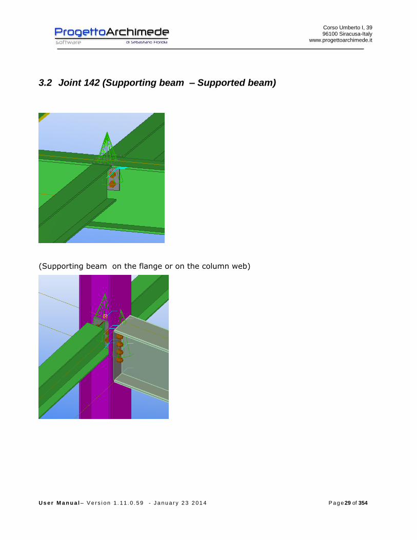
3.2 Joint 142 (Supporting beam – Supported beam)
(Supporting beam on the flange or on the column web)

Corso Umberto I, 39 96100 Siracusa-Italy
www.progettoarchimede.it
U s e r M a n u a l – V e r s i o n 1 . 1 1 . 0 . 5 9 - J a n u a r y 2 3 2 0 1 4 P a g e 30 of 354
3.2.1 Plates
The connection plate can be single or multiple
3.2.2 Actions
On the secondary profile we can apply the following forces:
EdN normal force (positive if tensile)
xEdV , horizontal shear force
yEdV , vertical plane shear force
xEdM , bending moment around x axis
The forces can be inserted by Tekla Structures (except xEdV , ), by modeler Midas, , by
text file or we can calculate the structure to restore strength.

Corso Umberto I, 39 96100 Siracusa-Italy
www.progettoarchimede.it
U s e r M a n u a l – V e r s i o n 1 . 1 1 . 0 . 5 9 - J a n u a r y 2 3 2 0 1 4 P a g e 31 of 354
If the stresses from Tekla Structures are zero, the forces will have minimum value
according with EC3 1-8 point 6.2.7.1.(13)
plEd NN 025.0
plyEd VV 025.0,
plEd MM 25.0
where the plastic design resistances are referred at the secondary profile
Generally the joint can be schematized as hinged joint that is as a constrained joint.
This type of connection, is generally used to ensure the continuity of supported beam,
beam – continuous beam ( constrained joint on both secondary profiles), or simulate
some hinges on one of two secondary profiles and a joint on the other profile, that is
like an hinge on both the secondary profiles.
Corso Umberto I, 39 96100 Siracusa-Italy
www.progettoarchimede.it
U s e r M a n u a l – V e r s i o n 1 . 1 1 . 0 . 5 9 - J a n u a r y 2 3 2 0 1 4 P a g e 32 of 354
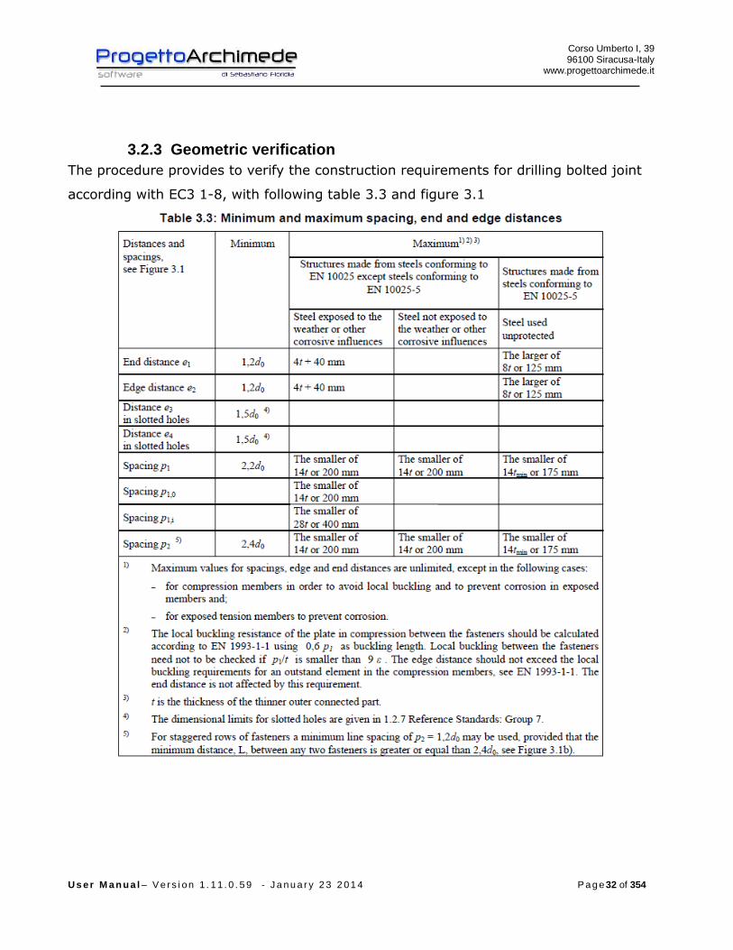
3.2.3 Geometric verification
The procedure provides to verify the construction requirements for drilling bolted joint
according with EC3 1-8, with following table 3.3 and figure 3.1

Corso Umberto I, 39 96100 Siracusa-Italy
www.progettoarchimede.it
U s e r M a n u a l – V e r s i o n 1 . 1 1 . 0 . 5 9 - J a n u a r y 2 3 2 0 1 4 P a g e 33 of 354
3.2.3.1 Design resistance of the single bolt and the single weld
In this section we recall the common criterions for verification of single bolts and single
weld.

Corso Umberto I, 39 96100 Siracusa-Italy
www.progettoarchimede.it
U s e r M a n u a l – V e r s i o n 1 . 1 1 . 0 . 5 9 - J a n u a r y 2 3 2 0 1 4 P a g e 34 of 354
3.2.3.2 Tension design resistance of the bolt
Single bolt tension resistance is:
2,
9.0
M
subRdt
AfF
Where
sA is the tensile stressed area
ubf is the last tensile bolt strength
3.2.3.3 Design resistance of the bolt to shear
For a shear connection (see class A EC3 1-8 point 3.4.1) the single bolt shear force
design (for only one resistant section) is:
2
,,M
ubvRdv
AfF
If the shear force plane is through the threated bolt portion:
- for classes 4.6, 5.6 and 8.8
6.0v
- for classes 4.8, 5.8 and 10.9
5.0v
If the shear force plane is through not threaded bolt portion:
6.0v
While
A is bolt area
ubf is the last bolt tension
3.2.3.4 Design resistance of the Weld
Fillet weld design resistance is:

Corso Umberto I, 39 96100 Siracusa-Italy
www.progettoarchimede.it
U s e r M a n u a l – V e r s i o n 1 . 1 1 . 0 . 5 9 - J a n u a r y 2 3 2 0 1 4 P a g e 35 of 354
lafF dvwRdw .,
Where
dvwf . is the welding shear design resistance.
a is weld throat height.
l is weld throat height.
The welding shear resistance calculation dvwf . is:
2.
3/
Mw
udvw
ff
Where :
uf is the nominal resistance breaking of weaker joint;
w is the appropriate correlation factor shown in table 4.1.

Corso Umberto I, 39 96100 Siracusa-Italy
www.progettoarchimede.it
U s e r M a n u a l – V e r s i o n 1 . 1 1 . 0 . 5 9 - J a n u a r y 2 3 2 0 1 4 P a g e 36 of 354
3.2.3.5 Annotations
In the verifications the sizes regarding supported beam will have the pedice wb and
regarding supporting beam the pedice wc.
3.2.3.6 Verifications made
- Verifications made on the joint are the following:
- Weld on the supported beam
RdwEdw FF ,,
- Shear and tension force bolt on the supporting beam
tensionandshear of caseIn 4.1//
ononly tensi of caseIn
shearonly of caseIn
,,,,
,,
,,
RdtEdtRdvEdv
RdtEdt
RdvEdv
FFFF
FF
FF
- Net and gross sections verification of profile and plates on supported beam, due
to stress tensile and shear force
Rdu
RdplEd N
NN
,
,
Rdu
RdplEd V
VV
,
,
- BlockTearing verification profiles and plates on the supported beam, due to
tensile and shear force
effEd NN
effEd VV
- Bearing resistance verification on two directions, horizontal and vertical of
profiles and plate on supported beam
Corso Umberto I, 39 96100 Siracusa-Italy
www.progettoarchimede.it
U s e r M a n u a l – V e r s i o n 1 . 1 1 . 0 . 5 9 - J a n u a r y 2 3 2 0 1 4 P a g e 37 of 354
- RdbEdb FF ,,
3.2.3.7 Verification of weld (supported beam)
Verification is done considering together perpendicular force and shear acting on the
supported beam.
If we consider a reference system x-y on supported beam plan, with x coincident with
beam axis , y orthogonal beam axis and the origin in vertical cordon barycenter, for
equilibrium to vertical translation and rotation relative to supporting beam axis, we
consider as that vertical cordon on supported beam is for the whole height plate.
The forces on plate are:
eVT
VV
NV
yEd
yEdy
Edx
,
Where
e is the distance between vertical welding barycenter and supporting beam axis, while
EdT is the parasite torsion had to eccentricity, if the main supporting beam torsional
stiffness isn’t negligible, the connection is assumed as a constraint joint and
xEdyEd MeVT , .
The horizontal and vertical actions on single weld are:
)(2
)(
2)(
,
,
,
EdEdEdx
yyEdy
xxEdx
TTV
VVV
VVV
Force resultant on horizontal welding is
)()()(( ,,,,, yEdyEdEdxxEdxEdxw VVTVVVF

Corso Umberto I, 39 96100 Siracusa-Italy
www.progettoarchimede.it
U s e r M a n u a l – V e r s i o n 1 . 1 1 . 0 . 5 9 - J a n u a r y 2 3 2 0 1 4 P a g e 38 of 354
must satisfy:
RdwEdw FF ,,
Where
l is single cordon length
a is throat height.
3.2.3.8 Shear and tension verification of the bolt (supporting beam)
The verification is made considering together normal stress bending and shear force
acting on supported beam, as the sum of the forces transmitted by the supported
beam. If we consider a reference system x-y on supporting beam’s plan, with axis x
coincident with beam’s axis, axis y orthogonal to beam’s axis and origin in the bolt’ s
barycenter that are on one angular, for vertical translation and rotation equilibrium
relative to the supported beam axis, shear force solicitations in the group bolt’s
barycenter on single bracket are:
eVT
VV
VV
yEd
yEdy
xEdx
2/
2/
,
,
If on supporting beam is only one angular the stresses on the group bolts’ barycenter
on bracket are:
eVT
VV
VV
yEd
yEdy
xEdx
,
,
Where
e is the distance between the group bolts’ barycenter of single angular and supported
beam’s axis, while EdT is the parasite torsion had to eccentricity.
The shear forces on the single bolt for single bolt shear plan are:

Corso Umberto I, 39 96100 Siracusa-Italy
www.progettoarchimede.it
U s e r M a n u a l – V e r s i o n 1 . 1 1 . 0 . 5 9 - J a n u a r y 2 3 2 0 1 4 P a g e 39 of 354
ibv
EdEdEdy
ibv
EdEdEdx
bv
yyEdy
bv
xxEdx
xJn
TTV
yJn
TTV
nn
VVV
nn
VVV
)(
)(
)(
)(
,
,
,
,
With
)( 22 ynxnJ bh
i
bvb bolts polar moment
bn bolts total number
vn bolt sections number shear resistant
bhn bolts number per horizontal row
bvn bolts number per vertical row
ix single bolt distance from barycenter of group bolts, in verification we consider maxx
iy single bolt distance from barycenter of group bolts, in verification we consider maxy
The forces resultant on single bolt for single bolt shear plan is:
2,,
2,,, ))()(())()(( EdEdyyEdyEdEdxxEdxEdv TVVVTVVVF
The tension force on single bolt belonging to the group of bolts of a bracket is:
bEdt nNF /,
If the constraint of the supported beam is similar to a joint , the bending force resulting
from supported beam is tensile stressed and the tensile force on single bolt belonging
to the group of bolts of a side of plate is:
ib
xEdbi
i
bh
xEdbEdt y
I
MnNy
yn
MnNF
,
2
,, //
bn bolts total number
bhn bolts total number for horizontal row
Corso Umberto I, 39 96100 Siracusa-Italy
www.progettoarchimede.it
U s e r M a n u a l – V e r s i o n 1 . 1 1 . 0 . 5 9 - J a n u a r y 2 3 2 0 1 4 P a g e 40 of 354
iy distance of single bolts row from compression center (the compression center coincides with
the lower edge of the bracket), in the verifications we consider the maxy .
must satisfy
trazionee tagliodi presenzaIn 4.1//
trazionesola di presenzaIn
tagliosolo di presenzaIn
,,,,
,,
,,
RdtEdtRdvEdv
RdtEdt
RdvEdv
FFFF
FF
FF
3.2.4 Net and gross sections verification (supported beam)
The verification is made both for normal tension forces and shear forces.
3.2.4.1 Tension force
The verification made both for the profile and plates should satisfy if:
1,
Rdt
Ed
N
N
Where RdtN , is the design resistance force at tension force of section cross ,
equal to lower of:
c) Plastic design resistance of gross section
0,
M
y
Rdpl
AfN
d) Ultimate design resistance of net section in holes for devices connection
2, 9.0
M
ynet
Rdu
fAN

Corso Umberto I, 39 96100 Siracusa-Italy
www.progettoarchimede.it
U s e r M a n u a l – V e r s i o n 1 . 1 1 . 0 . 5 9 - J a n u a r y 2 3 2 0 1 4 P a g e 41 of 354
The tensile force is equal to horizontal shear force acting on supporting beam.
The axis is the profile resistant part, with height equal to plate height in
according with EC3.
The verification is made for single side plate
3.2.4.2 Shear force
The verification is made both for profile and plates should verify :
1,
Rdc
Ed
V
V
Where RdcV , is the shear design resistance force of cross section, equal to lower of:
c) Plastic design resistance of gross section
0,
)3/(
M
y
Rdpl
fAV
d) Ultimate resistance design section of net section in hole for connection
devices
2,
)3/(
M
unetRdu
fAV
The axis is the profile resistant part.
The plate resistant part is the sum of single cross area.
3.2.5 Resistance for Block Tearing
- The shear force resistance with collapse mechanism “block Tearing” (EC3 – 1.8
point 3.10.2), is characterized by two possible crisis mode:
- Tensile force breaking along line holes and shear force section yield on gross
section;
- Shear force breaking on net section

Corso Umberto I, 39 96100 Siracusa-Italy
www.progettoarchimede.it
U s e r M a n u a l – V e r s i o n 1 . 1 1 . 0 . 5 9 - J a n u a r y 2 3 2 0 1 4 P a g e 42 of 354

Corso Umberto I, 39 96100 Siracusa-Italy
www.progettoarchimede.it
U s e r M a n u a l – V e r s i o n 1 . 1 1 . 0 . 5 9 - J a n u a r y 2 3 2 0 1 4 P a g e 43 of 354
For a group of bolts stressed by a symmetric force, the tear resistance,
RdeffV ,1, is:
02
,1,
3
M
nvy
M
ntuRdeff
AfAfV
where:
ntA is net area with tensile force;
nvA is net area with shear force.
For a group of bolts stressed by an eccentric shear force, RdeffV ,2, is given by
02
,2,
35.0
M
nvy
M
ntuRdeff
AfAfV

Corso Umberto I, 39 96100 Siracusa-Italy
www.progettoarchimede.it
U s e r M a n u a l – V e r s i o n 1 . 1 1 . 0 . 5 9 - J a n u a r y 2 3 2 0 1 4 P a g e 44 of 354
The verification is made separately both for perpendicular action and shear force
action, both for profile and angles.
Must be:
effEd NN
effEd VV
3.2.6 Single bolt bearing resistance force
The bearing verification for single bolt resistance section is:
2
1,,
M
ubRdb
dtfkF
Where b is
For external bolts
)1;3
;min(0
1
d
e
f
f
u
ubb
For inner bolts is
)1;4
1
3;min(
0
1 d
p
f
f
u
ubb
While 1k is
for external bolts
)5.2;7.18.2min(0
21
d
ek
For internal bolts
)5.2;7.14.1min(0
21
d
pk
Where
uf is the ultimate tensile strength of lower resistant plate
ubf is the bolt ultimate tensile strength
t is minimum thickness of plates connection

Corso Umberto I, 39 96100 Siracusa-Italy
www.progettoarchimede.it
U s e r M a n u a l – V e r s i o n 1 . 1 1 . 0 . 5 9 - J a n u a r y 2 3 2 0 1 4 P a g e 45 of 354
0d is hole diameter
For the other sizes definition see figure 3.1
The bearing verification is made separately on two horizontal and vertical directions
both profile and supported and supporting beam angles. In the verification vertical and
horizontal shear forces acting on local reference system, are combined.
Must be:
RdbEdb FF ,,
Corso Umberto I, 39 96100 Siracusa-Italy
www.progettoarchimede.it
U s e r M a n u a l – V e r s i o n 1 . 1 1 . 0 . 5 9 - J a n u a r y 2 3 2 0 1 4 P a g e 46 of 354
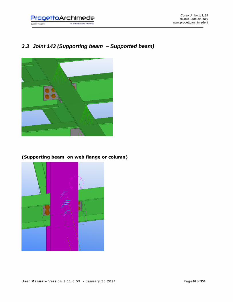
3.3 Joint 143 (Supporting beam – Supported beam)
(Supporting beam on web flange or column)
Corso Umberto I, 39 96100 Siracusa-Italy
www.progettoarchimede.it
U s e r M a n u a l – V e r s i o n 1 . 1 1 . 0 . 5 9 - J a n u a r y 2 3 2 0 1 4 P a g e 47 of 354
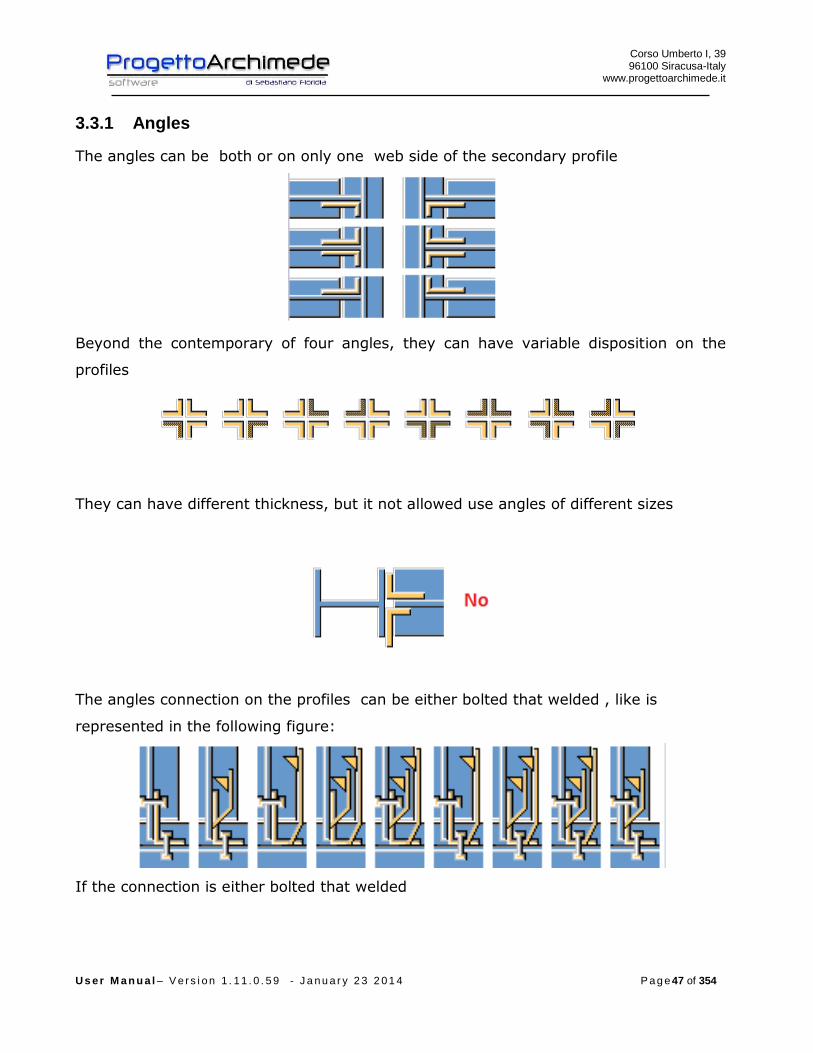
3.3.1 Angles
The angles can be both or on only one web side of the secondary profile
Beyond the contemporary of four angles, they can have variable disposition on the
profiles
They can have different thickness, but it not allowed use angles of different sizes
The angles connection on the profiles can be either bolted that welded , like is
represented in the following figure:
If the connection is either bolted that welded
Corso Umberto I, 39 96100 Siracusa-Italy
www.progettoarchimede.it
U s e r M a n u a l – V e r s i o n 1 . 1 1 . 0 . 5 9 - J a n u a r y 2 3 2 0 1 4 P a g e 48 of 354
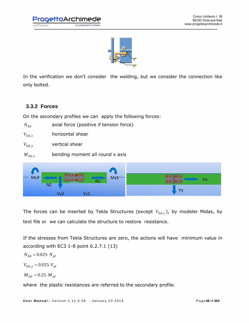
In the verification we don’t consider the welding, but we consider the connection like
only bolted.
3.3.2 Forces
On the secondary profiles we can apply the following forces:
EdN axial force (positive if tension force)
xEdV , horizontal shear
yEdV , vertical shear
xEdM , bending moment all round x axis
The forces can be inserted by Tekla Structures (except xEdV , ), by modeler Midas, by
text file or we can calculate the structure to restore resistance.
If the stresses from Tekla Structures are zero, the actions will have minimum value in
according with EC3 1-8 point 6.2.7.1 (13)
plEd NN 025.0
plyEd VV 025.0,
plEd MM 25.0
where the plastic resistances are referred to the secondary profile.

Corso Umberto I, 39 96100 Siracusa-Italy
www.progettoarchimede.it
U s e r M a n u a l – V e r s i o n 1 . 1 1 . 0 . 5 9 - J a n u a r y 2 3 2 0 1 4 P a g e 49 of 354
The joint can be generally schematized as hinged joint that is considered like joint
node .
This type of connection, is generally used to ensure the supported beam continuity,
beam – continuous beam (constraint joint on both secondary profile), or simulate
hinges on one of the two secondary profiles and a constrained on the other, that is
hinge on both secondary profiles
3.3.3 Geometric verification
The procedure provides to verify the construction requirements for drilling bolted
joint, in according with l’EC3 1-8 with the following table 3.3 and figure 3.1.

Corso Umberto I, 39 96100 Siracusa-Italy
www.progettoarchimede.it
U s e r M a n u a l – V e r s i o n 1 . 1 1 . 0 . 5 9 - J a n u a r y 2 3 2 0 1 4 P a g e 50 of 354

Corso Umberto I, 39 96100 Siracusa-Italy
www.progettoarchimede.it
U s e r M a n u a l – V e r s i o n 1 . 1 1 . 0 . 5 9 - J a n u a r y 2 3 2 0 1 4 P a g e 51 of 354
3.3.4 Design resistance of single bolt and single weld
In this section we recall the common criteria for verification of single bolts and single
welds.

Corso Umberto I, 39 96100 Siracusa-Italy
www.progettoarchimede.it
U s e r M a n u a l – V e r s i o n 1 . 1 1 . 0 . 5 9 - J a n u a r y 2 3 2 0 1 4 P a g e 52 of 354
3.3.4.1 Design resistance tensile of the bolt
Tensile strength of single bolt is:
2,
9.0
M
subRdt
AfF
Where
sA is tensile stressed area
ubf is the last tensile of bolt
3.3.4.2 Bolt shear design resistance
For a shear connection (see class A EC3 1-8 point 3.4.1) the single bolt shear strength
design (for a single resistant section) is:
2
,,M
ubvRdv
AfF
If the shear plane is through the threaded bolt portion:
- for classes 4.6, 5.6 e 8.8
6.0v
- for classes 4.8, 5.8 e 10.9
5.0v
If the shear plane is through not threaded bolt portion:
6.0v
while
A is the bolt area
ubf is the last bolt tensile stress
3.3.4.3 Design resistance of the weld
Design resistance of fillet weld is:
lafF dvwRdw .,
Corso Umberto I, 39 96100 Siracusa-Italy
www.progettoarchimede.it
U s e r M a n u a l – V e r s i o n 1 . 1 1 . 0 . 5 9 - J a n u a r y 2 3 2 0 1 4 P a g e 53 of 354
where
dvwf . is weld shear design resistance.
a is height throat weld.
l is length cordon weld.
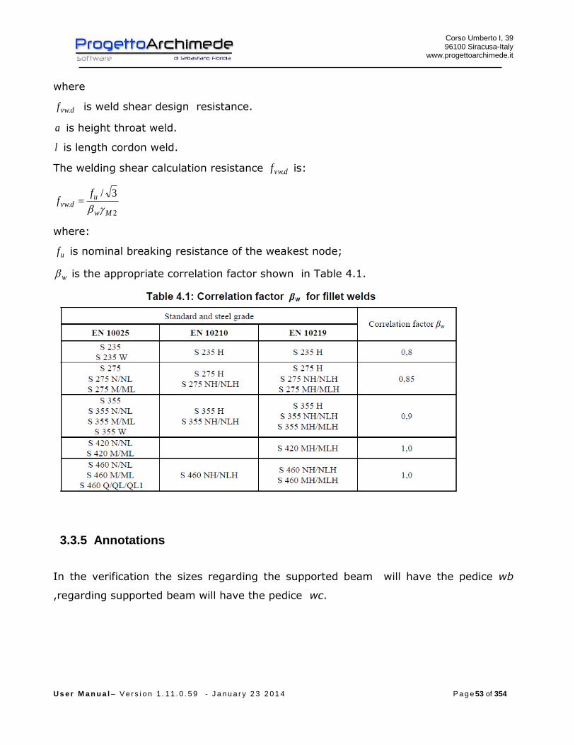
The welding shear calculation resistance dvwf . is:
2.
3/
Mw
udvw
ff
where:
uf is nominal breaking resistance of the weakest node;
w is the appropriate correlation factor shown in Table 4.1.
3.3.5 Annotations
In the verification the sizes regarding the supported beam will have the pedice wb
,regarding supported beam will have the pedice wc.
Corso Umberto I, 39 96100 Siracusa-Italy
www.progettoarchimede.it
U s e r M a n u a l – V e r s i o n 1 . 1 1 . 0 . 5 9 - J a n u a r y 2 3 2 0 1 4 P a g e 54 of 354
3.3.6 Verifications made
The verifications made on the joint are the following:
- Shear bolt on the supported beam
RdvEdv FF ,,
- Welding on the supported and supporting beam
RdwEdw FF ,,
- Bolt shear and tension force on the supporting beam
trazionee tagliodi presenzaIn 4.1//
trazionesola di presenzaIn
tagliosolo di presenzaIn
,,,,
,,
,,
RdtEdtRdvEdv
RdtEdt
RdvEdv
FFFF
FF
FF
- Verification of net and gross section of profiles and angles on the supported and
supporting beam, due tensile and shear action.
Rdu
RdplEd N
NN
,
,
Rdu
RdplEd V
VV
,
,
- Profiles and angles verification for Block Tearing on the supported and supporting
beam, due tensile and shear action.
-
effEd NN
effEd VV
- Bearing stress verification on the two profile and angle directions, horizontal and
vertical on the supported and supporting beam
RdbEdb FF ,,

Corso Umberto I, 39 96100 Siracusa-Italy
www.progettoarchimede.it
U s e r M a n u a l – V e r s i o n 1 . 1 1 . 0 . 5 9 - J a n u a r y 2 3 2 0 1 4 P a g e 55 of 354
3.3.7 Shear bolt verification (supported beam)
The verification is made considering together normal stress and shear acting on the
single supported beam.
If we consider a reference system x-y on the supported plan beam, with x axis
coincident with beam axis , y axis orthogonal to beam axis and the origin coincident
with bolts barycenter, for the equilibrium to the vertical translation and rotation relative
beam axis of supporting beam, stresses in the group bolts barycenter on the bracket of
single supported beam are:
eVT
VV
NV
yEd
yEdy
Edx
,
Where
e is the distance between the group bolts barycenter and supporting beam axis, while
EdT is the parasite torsion had to the eccentricity, if we consider the joint as
constrained xEdyEd MeVT , .
The shear forces on the single bolt, for single bolt shear plan are:
ibv
EdEdEdy
ibv
EdEdEdx
bv
yyEdy
bv
xxEdx
xJn
TTV
yJn
TTV
nn
VVV
nn
VVV
)(
)(
)(
)(
,
,
,
,
With
)( 22 ynxnJ bh
i
bvb bolts polar moment
bn bolts total number
vn shear resistant section number
Corso Umberto I, 39 96100 Siracusa-Italy
www.progettoarchimede.it
U s e r M a n u a l – V e r s i o n 1 . 1 1 . 0 . 5 9 - J a n u a r y 2 3 2 0 1 4 P a g e 56 of 354
bhn bolts number for each horizontal row
bvn bolts number for each vertical row
ix single bolt distance from group bolts barycenter, in the verification we consider the maxx
iy single bolt distance from group bolts barycenter, in the verification we consider the maxy
The force resultant on single bolt for single bolt shear plan is:
2,,
2,,, ))()(())()(( EdEdyyEdyEdEdxxEdxEdv TVVVTVVVF
Must satisfy:
RdvEdv FF ,,
3.3.8 Verification of the Welding (supported beam)
The verification is made considering together perpendicular stress and shear force
acting on the supported beam.
If we consider a reference system x-y on the supported plan beam, with x axis
coincident with beam axis , y axis orthogonal to beam axis and the origin coincident
with vertical welding barycenter, for the equilibrium to the vertical translation and
rotation relative beam axis of supporting beam, must be for each angle two horizontal
welding ( one superior and one inferior) and one vertical weld on the supported beam.
The stresses on the bracket are:
eVT
VV
NV
yEd
yEdy
Edx
,
Where
e is the distance between the vertical weld barycenter and supporting beam axis, while
EdT is the parasite torsion due to the eccentricity, if we consider the joint as
constrained xEdyEd MeVT , .

Corso Umberto I, 39 96100 Siracusa-Italy
www.progettoarchimede.it
U s e r M a n u a l – V e r s i o n 1 . 1 1 . 0 . 5 9 - J a n u a r y 2 3 2 0 1 4 P a g e 57 of 354
The horizontal and vertical forces on the welding are:
)(
)(2
)(
,
,
,
hangles
EdEdEdx
yyEdy
xxEdx
h
TTV
VVV
VVV
With
hanglesh angle height
The forces resultant on the horizontal welding is:
)()(( ,,,, EdEdxxEdxEdxw TVVVF
The forces resultant on the vertical welding is:
)(,,, yEdyEdyw VVF
must satisfy:
RdwEdw FF ,,
With
lafF dvwRdw ., one angle
2., lafF dvwRdw two angles
Where
l is the single cordon length
a is the throat height .
Corso Umberto I, 39 96100 Siracusa-Italy
www.progettoarchimede.it
U s e r M a n u a l – V e r s i o n 1 . 1 1 . 0 . 5 9 - J a n u a r y 2 3 2 0 1 4 P a g e 58 of 354
3.3.9 Shear and tensile force verification (supporting beam)
The verification is made considering together perpendicular stress and shear force
acting on the supported beam, as the sum of the supported beams forces .
If we consider a reference system x-y on the supporting plan beam, with x axis
coincident with beam axis , y axis orthogonal to beam axis and the origin coincident
with bolts barycenter that are on one angle, for the equilibrium to the vertical
translation and rotation relative beam axis of supported beam, stresses in the group
bolts barycenter on the bracket of single supported beam are:
eVT
VV
VV
yEd
yEdy
xEdx
2/
2/
,
,
If on the supporting beam there is only one angular the stresses on the group bolts’
barycenter on bracket are:
eVT
VV
VV
yEd
yEdy
xEdx
,
,
where
e is the distance between the group bolts’ barycenter of single angular and supported
beam’s axis, while EdT is the parasite torsion due to the eccentricity.
The shear forces of single bolt for single bolt shear plan are:
ibv
EdEdEdy
ibv
EdEdEdx
bv
yyEdy
bv
xxEdx
xJn
TTV
yJn
TTV
nn
VVV
nn
VVV
)(
)(
)(
)(
,
,
,
,
Corso Umberto I, 39 96100 Siracusa-Italy
www.progettoarchimede.it
U s e r M a n u a l – V e r s i o n 1 . 1 1 . 0 . 5 9 - J a n u a r y 2 3 2 0 1 4 P a g e 59 of 354
with
)( 22 ynxnJ bh
i
bvb bolts polar moment
bn bolts total number
vn bolts’ section numbers shear resistant
bhn bolts number per horizontal row
bvn bolts number per vertical row
ix single bolt distance from barycenter of group bolts, in verification we consider maxx
iy single bolt distance from barycenter of group bolts, in verification we consider maxy
The forces resultant on single bolt for single bolt shear plan is:
2,,
2,,, ))()(())()(( EdEdyyEdyEdEdxxEdxEdv TVVVTVVVF
The tension force on single bolt belonging to the group of bolts of a bracket is :
bEdt nNF /,
If we assume the supported beam connection like a constrained joint, the bending force
coming from supported beam is stressed to tension and the tension force on the single
bolt belonging to the group of bolts of a bracket is:
ib
xEdbi
i
bh
xEdbEdt y
I
MnNy
yn
MnNF
,
2
,, //
bn bolts total number
bhn bolts total number per horizontal row
iy single row bolts from the compression center (the center of compression coincides with the
lower edge of the bracket), in the verification we consider maxy .
Corso Umberto I, 39 96100 Siracusa-Italy
www.progettoarchimede.it
U s e r M a n u a l – V e r s i o n 1 . 1 1 . 0 . 5 9 - J a n u a r y 2 3 2 0 1 4 P a g e 60 of 354
must satisfy:
trazionee tagliodi presenzaIn 4.1//
trazionesola di presenzaIn
tagliosolo di presenzaIn
,,,,
,,
,,
RdtEdtRdvEdv
RdtEdt
RdvEdv
FFFF
FF
FF
3.3.10 Verification of the weld (supporting beam)
The verification is made considering together axial force, bending and shear force
acting, in two directions vertical and horizontal on supporting beam.
If we consider a reference system x-y on supporting beam’s plan, with axis x
coincident with beam’s axis, axis y orthogonal to beam’s axis and origin in barycenter
of vertical axis welding, for vertical translation and rotation equilibrium relative to the
supporting beam axis, must be for each angler two horizontal welding ( one superior
and one inferior) and one vertical weld on supporting beam.
Stresses on single bracket are:
eVT
MM
VV
VV
NN
yEd
xEdx
yEdy
xEdx
Edz
2/
2/
2/
2/
,
,
,
,
If on supporting beam there is only one angle the forces on the bracket are:
eVT
MM
VV
VV
NN
yEd
xEdx
yEdy
xEdx
Edz
,
,
,
,
Corso Umberto I, 39 96100 Siracusa-Italy
www.progettoarchimede.it
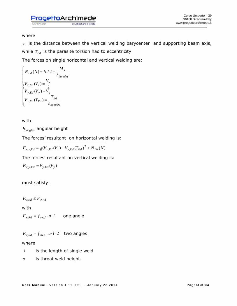
U s e r M a n u a l – V e r s i o n 1 . 1 1 . 0 . 5 9 - J a n u a r y 2 3 2 0 1 4 P a g e 61 of 354
where
e is the distance between the vertical welding barycenter and supporting beam axis,
while EdT is the parasite torsion had to eccentricity.
The forces on single horizontal and vertical welding are:
)(
)(2
)(
2/)(
,
,
,
hangles
EdEdEdx
yyEdy
xxEdx
hangles
xEd
h
TTV
VVV
VVV
h
MNNN
with
hanglesh angular height
The forces’ resultant on horizontal welding is:
)()()(( 2,,,, NNTVVVF EdEdEdxxEdxEdxw
The forces’ resultant on vertical welding is:
)(,,, yEdyEdyw VVF
must satisfy:
RdwEdw FF ,,
with
lafF dvwRdw ., one angle
2., lafF dvwRdw two angles
where
l is the length of single weld
a is throat weld height.

Corso Umberto I, 39 96100 Siracusa-Italy
www.progettoarchimede.it
U s e r M a n u a l – V e r s i o n 1 . 1 1 . 0 . 5 9 - J a n u a r y 2 3 2 0 1 4 P a g e 62 of 354
3.3.11 Verification net and gross sections (supported beam)
The verification is made both for normal tension forcer and shear force.
3.3.11.1 Tension force
The verification made both for the profile and angles is verified if:
1,
Rdt
Ed
N
N
where RdtN , is the design resistance force at tension force, equal to lower of:
e) Plastic design resistance of gross section
0,
M
y
Rdpl
AfN
f) Ultimate design resistance of net section in holes for connection devices
2, 9.0
M
ynet
Rdu
fAN
The axis is the profile resistant part, with height equal to angular height in
according with EC3.
The angular resistant part is the sum of two angles cross section areas, if there
are both, that is a single angular.
3.3.11.2 Shear force
The verification is made both for profile and angles is verified if:
1,
Rdc
Ed
V
V
where RdcV , is the shear resistance design force of cross section, equal to lower of :
e) Plastic design resistance of gross section
Corso Umberto I, 39 96100 Siracusa-Italy
www.progettoarchimede.it
U s e r M a n u a l – V e r s i o n 1 . 1 1 . 0 . 5 9 - J a n u a r y 2 3 2 0 1 4 P a g e 63 of 354
0,
)3/(
M
y
Rdpl
fAV
Ultimate resistance design section of net section in holes for connection
devices
2,
)3/(
M
unetRdu
fAV
The axis is the profile resistant part, it will be eventually blunted .
The angular resistant part is the sum of two angles cross section, if there are
both , that is a single angular .
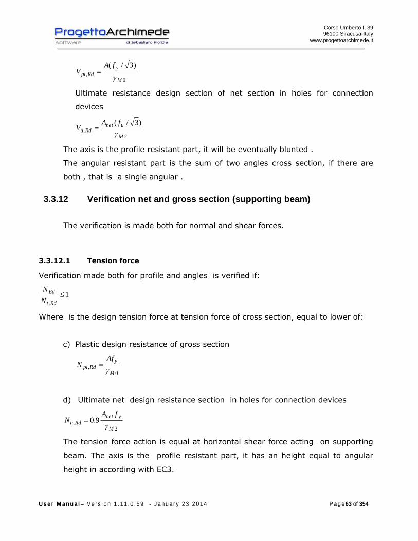
3.3.12 Verification net and gross section (supporting beam)
The verification is made both for normal and shear forces.
3.3.12.1 Tension force
Verification made both for profile and angles is verified if:
1,
Rdt
Ed
N
N
Where is the design tension force at tension force of cross section, equal to lower of:
c) Plastic design resistance of gross section
0,
M
y
Rdpl
AfN
d) Ultimate net design resistance section in holes for connection devices
2, 9.0
M
ynet
Rdu
fAN
The tension force action is equal at horizontal shear force acting on supporting
beam. The axis is the profile resistant part, it has an height equal to angular
height in according with EC3.

Corso Umberto I, 39 96100 Siracusa-Italy
www.progettoarchimede.it
U s e r M a n u a l – V e r s i o n 1 . 1 1 . 0 . 5 9 - J a n u a r y 2 3 2 0 1 4 P a g e 64 of 354
The verification is made for single angular.
3.3.12.2 Shear force
The verification made both for profile and angles is verified if :
1,
Rdc
Ed
V
V
Where RdcV , is the shear design resistance force of cross section, equal to lower of:
c) Plastic design resistance of gross section
0,
)3/(
M
y
Rdpl
fAV
d) Ultimate design resistance of net section in holes for joining devices
2,
)3/(
M
unetRdu
fAV
The axis is the profile resistant part
The angles resistant part is the sum each single cross area.
3.3.13 Resistance for Block Tearing
The shear force resistance with collapse mechanism “block Tearing” (EC3 – 1.8 point
3.10.2), is characterized by two possible crisis mode:
-Tensile force breaking along line holes and shear force section yield on gross
section;
-shear force breaking on net section.

Corso Umberto I, 39 96100 Siracusa-Italy
www.progettoarchimede.it
U s e r M a n u a l – V e r s i o n 1 . 1 1 . 0 . 5 9 - J a n u a r y 2 3 2 0 1 4 P a g e 65 of 354
For a group of bolts stressed by a symmetric force, tear resistance, RdeffV ,1, is:
02
,1,
3
M
nvy
M
ntuRdeff
AfAfV
where:
ntA is net area with tensile force;
nvA is net area with shear force.
For a group of bolts stressed by eccentric shear force action, RdeffV ,2, is:
02
,2,
35.0
M
nvy
M
ntuRdeff
AfAfV
The verification is made separately both for perpendicular action and shear force
action, both for profile and angles.

Corso Umberto I, 39 96100 Siracusa-Italy
www.progettoarchimede.it
U s e r M a n u a l – V e r s i o n 1 . 1 1 . 0 . 5 9 - J a n u a r y 2 3 2 0 1 4 P a g e 66 of 354
Must be:
effEd NN
effEd VV
3.3.14 Single bolt bearing resistance force
The bearing verification for single bolt resistance section is:
2
1,,
M
ubRdb
dtfkF
Where b is
For external bolts
)1;3
;min(0
1
d
e
f
f
u
ubb
For internal bolts is
)1;4
1
3;min(
0
1 d
p
f
f
u
ubb
While 1k is
For external bolts
)5.2;7.18.2min(0
21
d
ek
For internal bolts
)5.2;7.14.1min(0
21
d
pk
Where
uf is the ultimate tensile strength of lower resistant plate
ubf is the ultimate tensile strength of the bolt
t is minimum thickness of plates connection
0d is the diameter of hole
For the other sizes definition see figure 3.1

Corso Umberto I, 39 96100 Siracusa-Italy
www.progettoarchimede.it
U s e r M a n u a l – V e r s i o n 1 . 1 1 . 0 . 5 9 - J a n u a r y 2 3 2 0 1 4 P a g e 67 of 354
The bearing verification is made separately on two horizontal and vertical directions
both profile and supported and supporting beam angles. In the verification vertical and
horizontal shear forces acting on local reference system, are combined.
Must be:
RdbEdb FF ,,
Corso Umberto I, 39 96100 Siracusa-Italy
www.progettoarchimede.it
U s e r M a n u a l – V e r s i o n 1 . 1 1 . 0 . 5 9 - J a n u a r y 2 3 2 0 1 4 P a g e 68 of 354
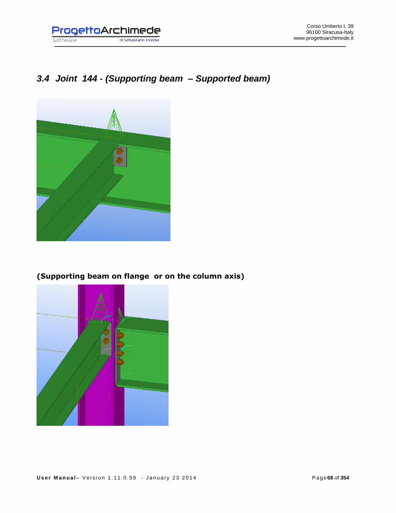
3.4 Joint 144 - (Supporting beam – Supported beam)
(Supporting beam on flange or on the column axis)
Corso Umberto I, 39 96100 Siracusa-Italy
www.progettoarchimede.it
U s e r M a n u a l – V e r s i o n 1 . 1 1 . 0 . 5 9 - J a n u a r y 2 3 2 0 1 4 P a g e 69 of 354
3.4.1 Plates
The connection plate can be single or multiple
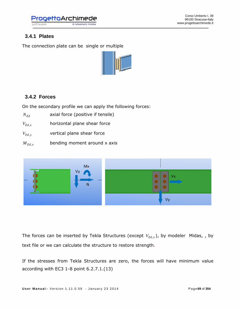
3.4.2 Forces
On the secondary profile we can apply the following forces:
EdN axial force (positive if tensile)
xEdV , horizontal plane shear force
yEdV , vertical plane shear force
xEdM , bending moment around x axis
The forces can be inserted by Tekla Structures (except xEdV , ), by modeler Midas, , by
text file or we can calculate the structure to restore strength.
If the stresses from Tekla Structures are zero, the forces will have minimum value
according with EC3 1-8 point 6.2.7.1.(13)

Corso Umberto I, 39 96100 Siracusa-Italy
www.progettoarchimede.it
U s e r M a n u a l – V e r s i o n 1 . 1 1 . 0 . 5 9 - J a n u a r y 2 3 2 0 1 4 P a g e 70 of 354
plEd NN 025.0
plyEd VV 025.0,
where the plastic resistances are referred to the secondary profile .
Generally the joint can be schematized as hinged joint, if the supporting beam
torsional stiffness is negligible, or as constrained joint if the torsional stiffness of the
main supporting beam is not negligible. This joint generally is used for end connections.
3.4.3 Geometric verification
The procedure provides to verify the construction requirements for drilling bolted joint
according with EC3 1-8, with following table 3.3 and figure 3.1

Corso Umberto I, 39 96100 Siracusa-Italy
www.progettoarchimede.it
U s e r M a n u a l – V e r s i o n 1 . 1 1 . 0 . 5 9 - J a n u a r y 2 3 2 0 1 4 P a g e 71 of 354

Corso Umberto I, 39 96100 Siracusa-Italy
www.progettoarchimede.it
U s e r M a n u a l – V e r s i o n 1 . 1 1 . 0 . 5 9 - J a n u a r y 2 3 2 0 1 4 P a g e 72 of 354
3.4.4 Design resistance of single bolt and single weld
In this section we recall the common criteria for verification of single bolts and single
weld.

Corso Umberto I, 39 96100 Siracusa-Italy
www.progettoarchimede.it
U s e r M a n u a l – V e r s i o n 1 . 1 1 . 0 . 5 9 - J a n u a r y 2 3 2 0 1 4 P a g e 73 of 354
3.4.4.1 Design resistance at bolt’s tension force
Single bolt tension resistance is:
2,
9.0
M
subRdt
AfF
where
sA is the stressed area to tensile force
ubf is the last tensile bolt strength
3.4.4.2 Bolt shear force resistance design
For a shear connection (see class A EC3 1-8 point 3.4.1) the design resistance of
single bolt for shear force (for a single resistant section) is:
2
,,M
ubvRdv
AfF
If the shear force plane is through the threated bolt portion:
- for classes 4.6, 5.6 and 8.8
6.0v
- for classes 4.8, 5.8 and 10.9
5.0v
If the shear force plane is through not threaded bolt portion:
6.0v
While
A is bolt area
ubf is the last bolt tension
3.4.4.3 design resistance of the weld
Fillet weld design resistance is:
lafF dvwRdw .,
Where

Corso Umberto I, 39 96100 Siracusa-Italy
www.progettoarchimede.it
U s e r M a n u a l – V e r s i o n 1 . 1 1 . 0 . 5 9 - J a n u a r y 2 3 2 0 1 4 P a g e 74 of 354
dvwf . is the welding shear design resistance.
a is throat weld height.
l is cordon weld length.
The welding shear resistance calculation dvwf . is:
2.
3/
Mw
udvw
ff
where:
uf is the nominal resistance breaking of weaker joint;
w is the appropriate correlation factor shown in table 4.1.
3.4.5 Annotations
In the verifications the sizes regarding supported beam will have the pedice wb and
regarding supporting beam the pedice wc.
Corso Umberto I, 39 96100 Siracusa-Italy
www.progettoarchimede.it
U s e r M a n u a l – V e r s i o n 1 . 1 1 . 0 . 5 9 - J a n u a r y 2 3 2 0 1 4 P a g e 75 of 354
3.4.6 Verifications made
- Verifications made on the joint are the following
Weld on the supported beam
RdwEdw FF ,,
- Shear and tension force bolt on the supporting beam
trazionee tagliodi presenzaIn 4.1//
trazionesola di presenzaIn
tagliosolo di presenzaIn
,,,,
,,
,,
RdtEdtRdvEdv
RdtEdt
RdvEdv
FFFF
FF
FF
- Net and gross sections verification of profile and plates on supported beam, due
to stress tensile and shear force
-
Rdu
RdplEd N
NN
,
,
Rdu
RdplEd V
VV
,
,
- BlockTearing verification profiles and plates on the supported beam, due to
tensile and shear force
- effEd NN
effEd VV
- Bearing resistance verification on two directions, horizontal and vertical profiles
and plate on supported beam
RdbEdb FF ,,
3.4.7 Weld verification (supported beam)
Verification is done considering together perpendicular force and shear acting on the
supported beam.
If we consider a reference system x-y on supported beam plan, with x coincident with
beam axis , y orthogonal beam axis and the origin in vertical cordon barycenter, for
Corso Umberto I, 39 96100 Siracusa-Italy
www.progettoarchimede.it
U s e r M a n u a l – V e r s i o n 1 . 1 1 . 0 . 5 9 - J a n u a r y 2 3 2 0 1 4 P a g e 76 of 354
equilibrium to vertical translation and rotation relative to supporting beam axis, we
consider as that vertical cordon on supported beam is for the whole height plate.
The forces on plate are:
eVT
VV
NV
yEd
yEdy
Edx
,
Where
e is the distance between vertical welding barycenter and supporting beam axis, while
EdT is the parasite torsion due to eccentricity, if the main supporting beam torsional
stiffness is not negligible, the connection is assumed as a constraint joint and
xEdyEd MeVT , .
The horizontal and vertical actions on single weld is:
)(2
)(
2)(
,
,
,
EdEdEdx
yyEdy
xxEdx
TTV
VVV
VVV
Force resultant on horizontal welding is:
)()()(( ,,,,, yEdyEdEdxxEdxEdxw VVTVVVF
must satisfy:
RdwEdw FF ,,
Where
l is the length of single cordon
a is throat height.
Corso Umberto I, 39 96100 Siracusa-Italy
www.progettoarchimede.it
U s e r M a n u a l – V e r s i o n 1 . 1 1 . 0 . 5 9 - J a n u a r y 2 3 2 0 1 4 P a g e 77 of 354
3.4.8 Shear and tension force bolt verification (supporting beam)
The verification is made considering together normal stress bending and shear force
acting on supported beam.
If we consider a reference system x-y on supporting beam’s plan, with axis x
coincident with beam’s axis, axis y orthogonal to beam’s axis and origin in the bolt’ s
barycenter that are on one angular, for vertical translation and rotation equilibrium
relative to the supported beam axis, shear force solicitations in the group bolt’s
barycenter on single bracket are:
eVT
VV
VV
yEd
yEdy
xEdx
2/
2/
,
,
If on supporting beam is only one angular the stresses on the group bolts’ barycenter
on bracket are:
eVT
VV
VV
yEd
yEdy
xEdx
,
,
Where
e is the distance between the group bolts’ barycenter of single angular and supported
beam’s axis, while EdT is the parasite torsion due to eccentricity.
The shear forces of single bolt for single bolt shear plan are:
ibv
EdEdEdy
ibv
EdEdEdx
bv
yyEdy
bv
xxEdx
xJn
TTV
yJn
TTV
nn
VVV
nn
VVV
)(
)(
)(
)(
,
,
,
,
With
Corso Umberto I, 39 96100 Siracusa-Italy
www.progettoarchimede.it
U s e r M a n u a l – V e r s i o n 1 . 1 1 . 0 . 5 9 - J a n u a r y 2 3 2 0 1 4 P a g e 78 of 354
)( 22 ynxnJ bh
i
bvb bolts polar moment
bn bolts total number
vn bolt sections number shear resistant
bhn bolts number per horizontal row
bvn bolts number per vertical row
ix single bolt distance from barycenter of group bolts, in verification we consider maxx
iy single bolt distance from barycenter of group bolts, in verification we consider maxy
The forces resultant on single bolt for single bolt shear plan is:
2,,
2,,, ))()(())()(( EdEdyyEdyEdEdxxEdxEdv TVVVTVVVF
The tension force on single bolt belonging to the group of bolts of a bracket is:
bEdt nNF /,
if the main supporting beam torsional stiffness is not negligible the bolts for bending
force resulting from supported beam are tensile stressed and the tensile on single bolt
belonging to the group of bolts of a bracket is:
ib
xEdbi
i
bh
xEdbEdt y
I
MnNy
yn
MnNF
,
2
,, //
bn bolts total number
bhn bolts total number for horizontal rows
iy is the distance of the single bolt from the center of compression (the center of compression
coincides with the lower edge of the bracket), in the verification we have considered the maxy .
Must satisfy
tensionandshear of caseIn 4.1//
ononly tensi of caseIn
shearonly of caseIn
,,,,
,,
,,
RdtEdtRdvEdv
RdtEdt
RdvEdv
FFFF
FF
FF

Corso Umberto I, 39 96100 Siracusa-Italy
www.progettoarchimede.it
U s e r M a n u a l – V e r s i o n 1 . 1 1 . 0 . 5 9 - J a n u a r y 2 3 2 0 1 4 P a g e 79 of 354
3.4.9 Net and gross sections verification (supported beam)
The verification is made both for normal tension forces and shear forces.
3.4.9.1 Tension force
The verification made both for the profile and plates is verified if:
1,
Rdt
Ed
N
N
Where RdtN , is the design resistance force at tension force of section cross , equal to
lower of:
g) Plastic design resistance of gross section
0,
M
y
Rdpl
AfN
h) Ultimate design resistance of net section in holes for devices connection
2, 9.0
M
ynet
Rdu
fAN
The tensile force is equal to horizontal shear force acting on supporting beam.
The axis is the profile resistant part, with height equal to angular height in
according with EC3.
The verification is made for single angle.
3.4.9.2 Shear force
The verification is made both for profile and angles is verified if:
1,
Rdc
Ed
V
V
Corso Umberto I, 39 96100 Siracusa-Italy
www.progettoarchimede.it
U s e r M a n u a l – V e r s i o n 1 . 1 1 . 0 . 5 9 - J a n u a r y 2 3 2 0 1 4 P a g e 80 of 354
Where RdcV , is the shear resistance design force of cross section, equal to lower of:
f) Plastic design resistance of gross section
0,
)3/(
M
y
Rdpl
fAV
g) Ultimate resistance design section of net section in hole for connection
devices
2,
)3/(
M
unetRdu
fAV
The axis is the profile resistant part.
The angular resistant part is the sum of single cross area.
3.4.10 Resistance for Block Tearing
- The shear force resistance with collapse mechanism “block Tearing” (EC3 – 1.8
point 3.10.2), is characterized by two possible crisis mode:
- Tensile force breaking along line holes and shear force section yield on gross
section;
- Shear force breaking on net section

Corso Umberto I, 39 96100 Siracusa-Italy
www.progettoarchimede.it
U s e r M a n u a l – V e r s i o n 1 . 1 1 . 0 . 5 9 - J a n u a r y 2 3 2 0 1 4 P a g e 81 of 354
For a group of bolts stressed by a symmetric force, tear resistance,
RdeffV ,1, is given by:
02
,1,
3
M
nvy
M
ntuRdeff
AfAfV
where:
ntA is net area with tensile force;
nvA is net area with shear force.
For a group of bolts stressed by an eccentric shear force action, RdeffV ,2, is:
02
,2,
35.0
M
nvy
M
ntuRdeff
AfAfV
The verification is made separately both for perpendicular action and shear force
action, both for profile and angles.
Corso Umberto I, 39 96100 Siracusa-Italy
www.progettoarchimede.it
U s e r M a n u a l – V e r s i o n 1 . 1 1 . 0 . 5 9 - J a n u a r y 2 3 2 0 1 4 P a g e 82 of 354
Must be:
effEd NN
effEd VV
3.4.11 Single bolt bearing resistance force
The bearing verification for single bolt resistance section is:
2
1,,
M
ubRdb
dtfkF
Where b is
For external bolts
)1;3
;min(0
1
d
e
f
f
u
ubb
For inner bolts is
)1;4
1
3;min(
0
1 d
p
f
f
u
ubb
While 1k is
for external bolts
)5.2;7.18.2min(0
21
d
ek
For internal bolts
)5.2;7.14.1min(0
21
d
pk
Where
uf is the ultimate tensile strength of lower resistant plate
ubf is the bolt ultimate tensile strength
t is minimum thickness of plates connection
0d is the hole diameter
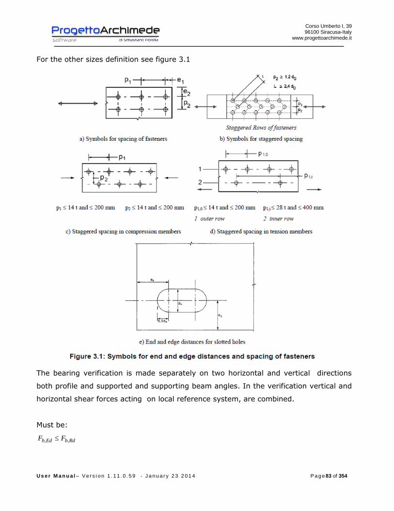
Corso Umberto I, 39 96100 Siracusa-Italy
www.progettoarchimede.it
U s e r M a n u a l – V e r s i o n 1 . 1 1 . 0 . 5 9 - J a n u a r y 2 3 2 0 1 4 P a g e 83 of 354
For the other sizes definition see figure 3.1
The bearing verification is made separately on two horizontal and vertical directions
both profile and supported and supporting beam angles. In the verification vertical and
horizontal shear forces acting on local reference system, are combined.
Must be:
RdbEdb FF ,,
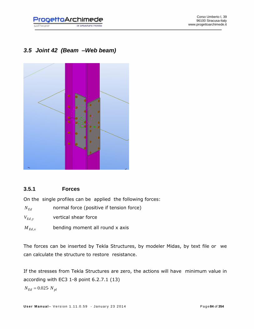
Corso Umberto I, 39 96100 Siracusa-Italy
www.progettoarchimede.it
U s e r M a n u a l – V e r s i o n 1 . 1 1 . 0 . 5 9 - J a n u a r y 2 3 2 0 1 4 P a g e 84 of 354
3.5 Joint 42 (Beam –Web beam)
3.5.1 Forces
On the single profiles can be applied the following forces:
EdN normal force (positive if tension force)
yEdV , vertical shear force
xEdM , bending moment all round x axis
The forces can be inserted by Tekla Structures, by modeler Midas, by text file or we
can calculate the structure to restore resistance.
If the stresses from Tekla Structures are zero, the actions will have minimum value in
according with EC3 1-8 point 6.2.7.1 (13)
plEd NN 025.0

Corso Umberto I, 39 96100 Siracusa-Italy
www.progettoarchimede.it
U s e r M a n u a l – V e r s i o n 1 . 1 1 . 0 . 5 9 - J a n u a r y 2 3 2 0 1 4 P a g e 85 of 354
plyEd VV 025.0,
plEd MM 25.0
where the plastic resistances are referred to lowest value of two profile resistance .
The connection is schematized as joint node.
This type of connection, is generally used to ensure the continuity of the interrupted
columns for reasons of the length of columns that are in commerce, or for design, the
joint also transmits moment, and it can be assumed as joint node.
3.5.1 Geometric verification
The procedure provides to verify the construction requirements for drilling bolted
joint, in according with l’EC3 1-8 and the following table 3.3 and figure 3.1.

Corso Umberto I, 39 96100 Siracusa-Italy
www.progettoarchimede.it
U s e r M a n u a l – V e r s i o n 1 . 1 1 . 0 . 5 9 - J a n u a r y 2 3 2 0 1 4 P a g e 86 of 354
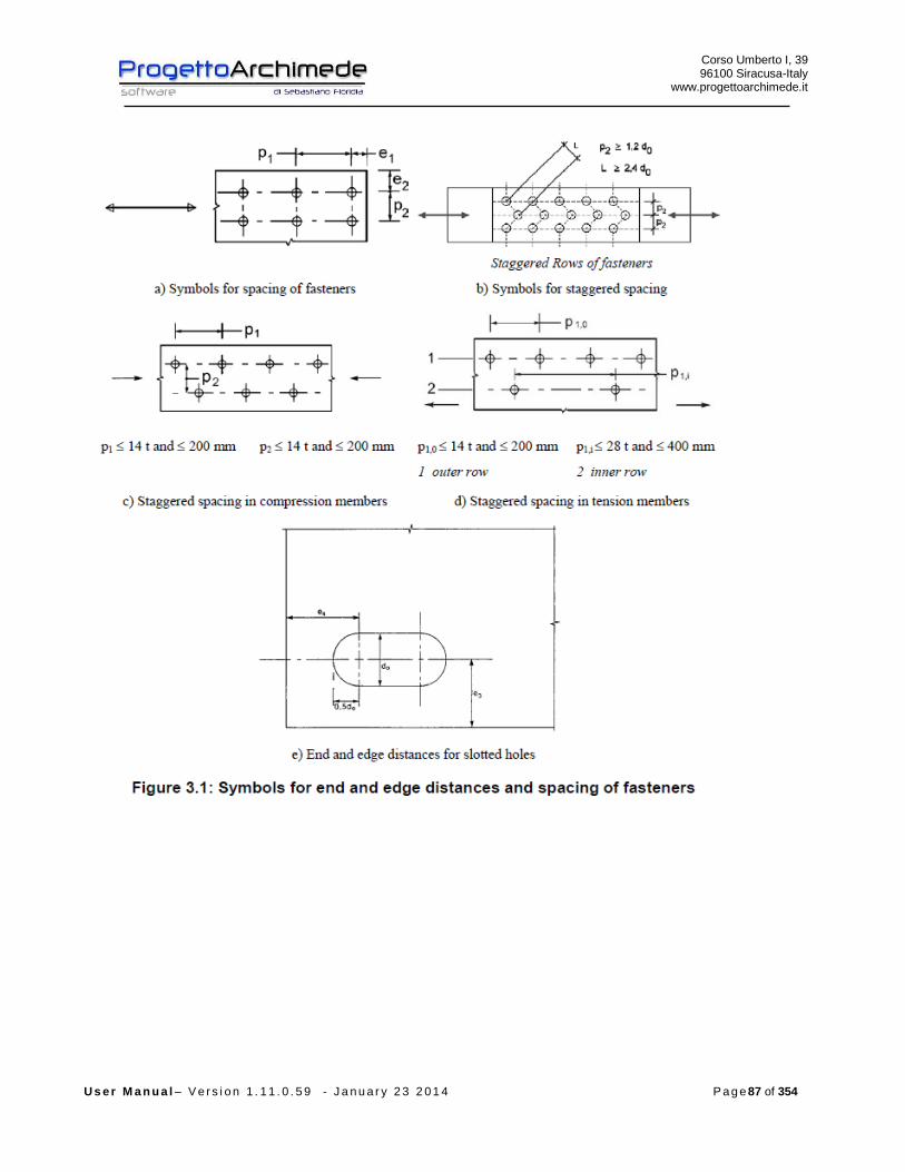
Corso Umberto I, 39 96100 Siracusa-Italy
www.progettoarchimede.it
U s e r M a n u a l – V e r s i o n 1 . 1 1 . 0 . 5 9 - J a n u a r y 2 3 2 0 1 4 P a g e 87 of 354
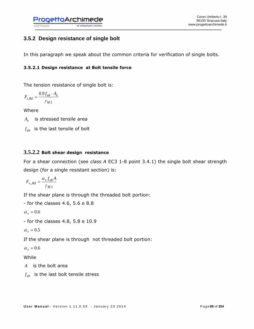
Corso Umberto I, 39 96100 Siracusa-Italy
www.progettoarchimede.it
U s e r M a n u a l – V e r s i o n 1 . 1 1 . 0 . 5 9 - J a n u a r y 2 3 2 0 1 4 P a g e 88 of 354
3.5.2 Design resistance of single bolt
In this paragraph we speak about the common criteria for verification of single bolts.
3.5.2.1 Design resistance at Bolt tensile force
The tension resistance of single bolt is:
2,
9.0
M
subRdt
AfF
Where
sA is stressed tensile area
ubf is the last tensile of bolt
3.5.2.2 Bolt shear design resistance
For a shear connection (see class A EC3 1-8 point 3.4.1) the single bolt shear strength
design (for a single resistant section) is:
2
,,M
ubvRdv
AfF
If the shear plane is through the threaded bolt portion:
- for the classes 4.6, 5.6 e 8.8
6.0v
- for the classes 4.8, 5.8 e 10.9
5.0v
If the shear plane is through not threaded bolt portion:
6.0v
While
A is the bolt area
ubf is the last bolt tensile stress

Corso Umberto I, 39 96100 Siracusa-Italy
www.progettoarchimede.it
U s e r M a n u a l – V e r s i o n 1 . 1 1 . 0 . 5 9 - J a n u a r y 2 3 2 0 1 4 P a g e 89 of 354
3.5.3 Annotations
In the verifications the sizes regarding beam wing will have the pedice fb for web
beam the pedice wb.
3.5.4 Verification made
The verifications made on the joint are the following:
- Shear bolt on the plate and web beam
RdvEdv FF ,,
- Net and gross sections verification of profiles and angles on supported and
supporting beam, due to stress tensile and shear force
-
Rdu
RdplEd N
NN
,
,
Rdu
RdplEd V
VV
,
,
- Bearing resistance verification on two directions, horizontal and vertical, of
profiles and angles on supported and supporting beam
RdbEdb FF ,,
3.5.5 Flange design resistance due to axial and bending force
It is assumed that the joint cover on the profile wing resist only at the applied design
moment EdjM , , the axial force together the axial design resistance EdjN , applied on
the single joint cover is:
2
,, Edj
copr
Edj N
tH
MF
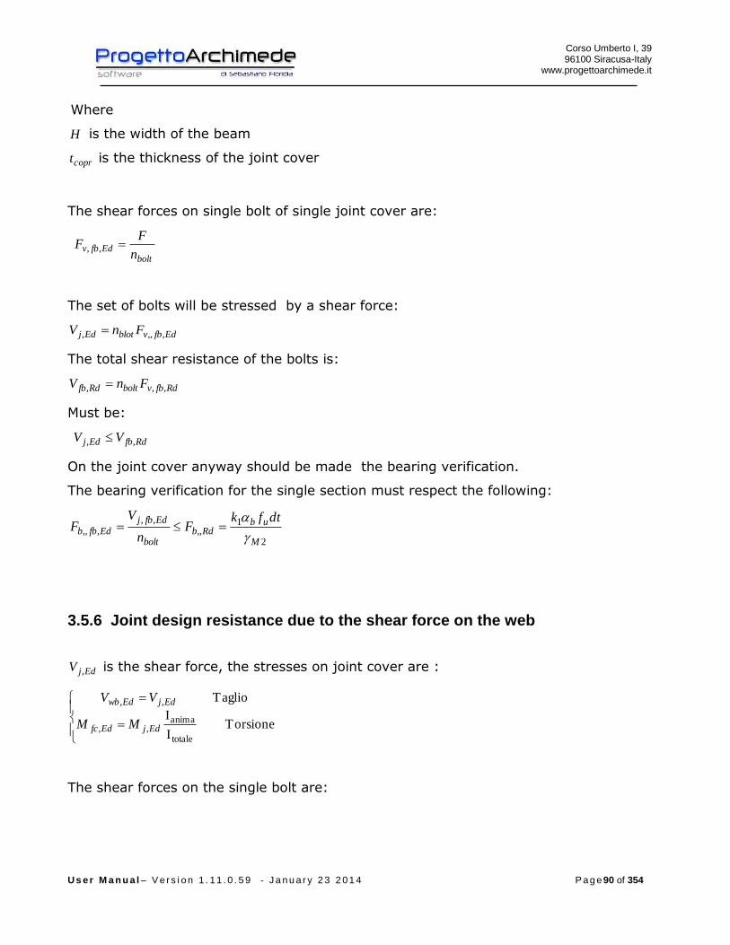
Corso Umberto I, 39 96100 Siracusa-Italy
www.progettoarchimede.it
U s e r M a n u a l – V e r s i o n 1 . 1 1 . 0 . 5 9 - J a n u a r y 2 3 2 0 1 4 P a g e 90 of 354
Where
H is the width of the beam
coprt is the thickness of the joint cover
The shear forces on single bolt of single joint cover are:
bolt
Edfbvn
FF ,,
The set of bolts will be stressed by a shear force:
EdfbvblotEdj FnV ,,,,
The total shear resistance of the bolts is:
RdfbvboltRdfb FnV ,,,
Must be:
RdfbEdj VV ,,
On the joint cover anyway should be made the bearing verification.
The bearing verification for the single section must respect the following:
2
1,,
,,,,,
M
ubRdb
bolt
EdfbjEdfbb
dtfkF
n
VF
3.5.6 Joint design resistance due to the shear force on the web
EdjV , is the shear force, the stresses on joint cover are :
Torsione I
I
Taglio
totale
anima,,
,,
EdjEdfc
EdjEdwb
MM
VV
The shear forces on the single bolt are:

Corso Umberto I, 39 96100 Siracusa-Italy
www.progettoarchimede.it
U s e r M a n u a l – V e r s i o n 1 . 1 1 . 0 . 5 9 - J a n u a r y 2 3 2 0 1 4 P a g e 91 of 354
eorizzontal Azione
vertivaleAzione
2
,,,,
,,,,
i
i
EdwcEdwcHv
bolt
EdwcEdwcVv
yy
MF
n
VF
Where
iy is the barycenter distance of single bolt from center of compression assumed on the
bolts barycenter.
The stressed force resultant is
2,,,,
2,,,,,,, EdwcHvEdwcVvEdwcv FFF
The set of bolts will be stressed by a shear force:
EdwcvblotEdwcj FnV ,,,,,
The total shear resistance of the bolts is:
RdwcvboltRdwc FnV ,,,
Must be :
RdwcEdwcj VV ,,,
On the joint cover anyway should be made the bearing verification.
The bearing verification for the single section must respect the following:
2
1,,
,,,,,
M
ubRdb
bolt
EdwcjEdwcb
dtfkF
n
VF
3.5.7 Verification of Net and gross sections
The verification is made both for normal tension forces and shear forces.
3.5.7.1 Tension force
The verification made both for the profile that for joint cover should satisfy if:
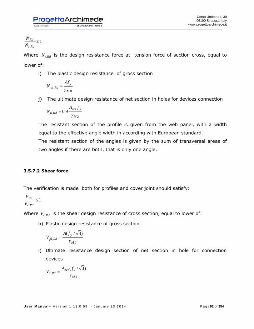
Corso Umberto I, 39 96100 Siracusa-Italy
www.progettoarchimede.it
U s e r M a n u a l – V e r s i o n 1 . 1 1 . 0 . 5 9 - J a n u a r y 2 3 2 0 1 4 P a g e 92 of 354
1,
Rdt
Ed
N
N
Where RdtN , is the design resistance force at tension force of section cross, equal to
lower of:
i) The plastic design resistance of gross section
0,
M
y
Rdpl
AfN
j) The ultimate design resistance of net section in holes for devices connection
2, 9.0
M
ynet
Rdu
fAN
The resistant section of the profile is given from the web panel, with a width
equal to the effective angle width in according with European standard.
The resistant section of the angles is given by the sum of transversal areas of
two angles if there are both, that is only one angle.
3.5.7.2 Shear force
The verification is made both for profiles and cover joint should satisfy:
1,
Rdc
Ed
V
V
Where RdcV , is the shear design resistance of cross section, equal to lower of:
h) Plastic design resistance of gross section
0,
)3/(
M
y
Rdpl
fAV
i) Ultimate resistance design section of net section in hole for connection
devices
2,
)3/(
M
unetRdu
fAV
Corso Umberto I, 39 96100 Siracusa-Italy
www.progettoarchimede.it
U s e r M a n u a l – V e r s i o n 1 . 1 1 . 0 . 5 9 - J a n u a r y 2 3 2 0 1 4 P a g e 93 of 354
The resistant section of cover joints is given by the sum of two transversal cover
joints if there are both, that is only one, that is only one cover joint.
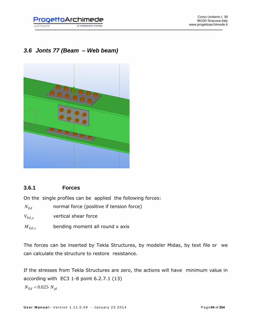
Corso Umberto I, 39 96100 Siracusa-Italy
www.progettoarchimede.it
U s e r M a n u a l – V e r s i o n 1 . 1 1 . 0 . 5 9 - J a n u a r y 2 3 2 0 1 4 P a g e 94 of 354
3.6 Jonts 77 (Beam – Web beam)
3.6.1 Forces
On the single profiles can be applied the following forces:
EdN normal force (positive if tension force)
yEdV , vertical shear force
xEdM , bending moment all round x axis
The forces can be inserted by Tekla Structures, by modeler Midas, by text file or we
can calculate the structure to restore resistance.
If the stresses from Tekla Structures are zero, the actions will have minimum value in
according with EC3 1-8 point 6.2.7.1 (13)
plEd NN 025.0
Corso Umberto I, 39 96100 Siracusa-Italy
www.progettoarchimede.it
U s e r M a n u a l – V e r s i o n 1 . 1 1 . 0 . 5 9 - J a n u a r y 2 3 2 0 1 4 P a g e 95 of 354
plyEd VV 025.0,
plEd MM 25.0
where the plastic resistances are referred to lowest value of two profile resistance .
The connection is schematized as joint node.
This type of connection, is generally used to ensure the continuity of the interrupted
columns for reasons of the length of columns that are in commerce, or for design, the
joint also transmits moment, and it can be assumed as joint node.

Corso Umberto I, 39 96100 Siracusa-Italy
www.progettoarchimede.it
U s e r M a n u a l – V e r s i o n 1 . 1 1 . 0 . 5 9 - J a n u a r y 2 3 2 0 1 4 P a g e 96 of 354
3.6.2 Geometric verification
The procedure provides to verify the construction requirements for drilling bolted
joint, in according with l’EC3 1-8 and the following table 3.3 and figure 3.1

Corso Umberto I, 39 96100 Siracusa-Italy
www.progettoarchimede.it
U s e r M a n u a l – V e r s i o n 1 . 1 1 . 0 . 5 9 - J a n u a r y 2 3 2 0 1 4 P a g e 97 of 354
Corso Umberto I, 39 96100 Siracusa-Italy
www.progettoarchimede.it
U s e r M a n u a l – V e r s i o n 1 . 1 1 . 0 . 5 9 - J a n u a r y 2 3 2 0 1 4 P a g e 98 of 354
3.6.3 Design resistance of single bolt
In this section we recall the common criteria for verification of single bolts.
3.6.3.1 Design resistance at Bolt tensile force
The tension resistance of single bolt is:
2,
9.0
M
subRdt
AfF
Where
sA is stressed tensile area
ubf is the last tensile of bolt
3.6.3.2 Bolt shear design resistance
For a shear connection (see class A EC3 1-8 point 3.4.1) the single bolt shear strength
design (for a single resistant section) is:
2
,,M
ubvRdv
AfF
If the shear plane is through the threaded bolt portion:
- for the classes 4.6, 5.6 e 8.8
6.0v
- for the classes 4.8, 5.8 e 10.9
5.0v
If the shear plane is through not threaded bolt portion:
6.0v
While
A is the bolt area
ubf is the last bolt tensile stress

Corso Umberto I, 39 96100 Siracusa-Italy
www.progettoarchimede.it
U s e r M a n u a l – V e r s i o n 1 . 1 1 . 0 . 5 9 - J a n u a r y 2 3 2 0 1 4 P a g e 99 of 354
3.6.4 Annotations
In the verifications the sizes regarding beam wing will have the pedice fb for web
beam the pedice wb.
3.6.5 Verifications made
The verifications made on the joint are the following:
Shear bolt on the plate and web beam
RdvEdv FF ,,
- Net and gross sections verification of profiles and angles on supported and
supporting beam, due to stress tensile and shear force
Rdu
RdplEd N
NN
,
,
Rdu
RdplEd V
VV
,
,
- Bearing resistance verification on two directions, horizontal and vertical, of
profiles and angles on supported and supporting beam
RdbEdb FF ,,
3.6.6 Flange design resistance due to axial and bending force
It is assumed that the joint cover on the profile wing resist only at the applied design
moment EdjM , , the axial force together the axial design resistance EdjN , applied on
the single joint cover is:
2
,, Edj
copr
Edj N
tH
MF
Where
H is the width of the beam

Corso Umberto I, 39 96100 Siracusa-Italy
www.progettoarchimede.it
U s e r M a n u a l – V e r s i o n 1 . 1 1 . 0 . 5 9 - J a n u a r y 2 3 2 0 1 4 P a g e 100 of 354
coprt is the thickness of the joint cover
The shear forces on single bolt of single joint cover are:
bolt
Edfbvn
FF ,,
The set of bolts will be stressed by a shear force:
EdfbvblotEdj FnV ,,,,
The total shear resistance of the bolts is:
RdfbvboltRdfb FnV ,,,
Must be:
RdfbEdj VV ,,
On the joint cover anyway should be made the bearing verification.
The bearing verification for the single section must respect the following:
2
1,,
,,,,,
M
ubRdb
bolt
EdfbjEdfbb
dtfkF
n
VF
3.6.7 Joint design resistance due to the shear force on the web
EdjV , is the shear force, the stresses on joint cover are:
Torsion I
I
Shear
total
web
,,
,,
EdjEdfc
EdjEdwb
MM
VV
The shear forces on the single bolt are:
Corso Umberto I, 39 96100 Siracusa-Italy
www.progettoarchimede.it
U s e r M a n u a l – V e r s i o n 1 . 1 1 . 0 . 5 9 - J a n u a r y 2 3 2 0 1 4 P a g e 101 of 354
force horizontal
force ical vert
2
,
,,,
,
,,,
i
i
Edwc
EdwcHv
bolt
Edwc
EdwcVv
yy
MF
n
VF
Where
iy is the barycenter distance of single bolt from center of compression assumed on the
bolts barycenter.
The stressed force resultant is
2,,,,
2,,,,,,, EdwcHvEdwcVvEdwcv FFF
The set of bolts will be stressed by a shear force:
EdwcvblotEdwcj FnV ,,,,,
The total shear resistance of the bolts is:
RdwcvboltRdwc FnV ,,,
Must be:
RdwcEdwcj VV ,,,
On the joint cover anyway should be made the bearing verification.
The bearing verification for the single section must respect the following:
2
1,,
,,,,,
M
ubRdb
bolt
EdwcjEdwcb
dtfkF
n
VF
3.6.8 Verification of Net and gross sections
The verification is made both for normal tension forces and shear forces.
3.6.8.1 Tension force
The verification made both for the profile that for joint cover should satisfy if:
1,
Rdt
Ed
N
N
Corso Umberto I, 39 96100 Siracusa-Italy
www.progettoarchimede.it
U s e r M a n u a l – V e r s i o n 1 . 1 1 . 0 . 5 9 - J a n u a r y 2 3 2 0 1 4 P a g e 102 of 354
Where RdtN , is the design resistance force at tension force of section cross, equal to
lower of:
k) The plastic design resistance of gross section
0,
M
y
Rdpl
AfN
l) The ultimate design resistance of net section in holes for devices connection
2, 9.0
M
ynet
Rdu
fAN
The resistant section of the profile is given from the web panel, with a width
equal to the effective angle width in according with European standard.
The resistant section of the angles is given by the sum of transversal areas of
two angles if there are both, that is only one angle.
3.6.8.2 Shear force
The verification is made both for profiles and cover joint should satisfy:
1,
Rdc
Ed
V
V
Where RdcV , is the shear design resistance of cross section, equal to lower of:
j) Plastic design resistance of gross section
0,
)3/(
M
y
Rdpl
fAV
k) Ultimate resistance design section of net section in hole for connection
devices
2,
)3/(
M
unetRdu
fAV
The resistant section of the joint cover is given by the sum of transversal areas
of two joint covers if there are both, that is only one joint cover.
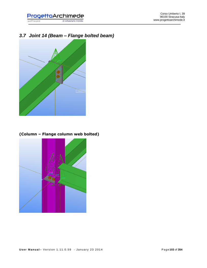
Corso Umberto I, 39 96100 Siracusa-Italy
www.progettoarchimede.it
U s e r M a n u a l – V e r s i o n 1 . 1 1 . 0 . 5 9 - J a n u a r y 2 3 2 0 1 4 P a g e 103 of 354
3.7 Joint 14 (Beam – Flange bolted beam)
(Column – Flange column web bolted)

Corso Umberto I, 39 96100 Siracusa-Italy
www.progettoarchimede.it
U s e r M a n u a l – V e r s i o n 1 . 1 1 . 0 . 5 9 - J a n u a r y 2 3 2 0 1 4 P a g e 104 of 354
3.7.1 Stiffeners on the beam
3.7.2 Forces
On the profiles can be applied the following forces:
EdN normal force (positive if tension force)
xEdV , horizontal shear
yEdV , vertical shear
xEdM , bending moment all round x axis
The forces can be inserted by Tekla Structures (except xEdV , ), by modeler Midas, by
text file or we can calculate the structure to restore resistance.
Corso Umberto I, 39 96100 Siracusa-Italy
www.progettoarchimede.it
U s e r M a n u a l – V e r s i o n 1 . 1 1 . 0 . 5 9 - J a n u a r y 2 3 2 0 1 4 P a g e 105 of 354
If the stresses from Tekla Structures are zero, the actions will have minimum value in
according with EC3 1-8 point 6.2.7.1 (13)
plEd NN 025.0
plyEd VV 025.0,
where the plastic resistances are referred to the column.

Corso Umberto I, 39 96100 Siracusa-Italy
www.progettoarchimede.it
U s e r M a n u a l – V e r s i o n 1 . 1 1 . 0 . 5 9 - J a n u a r y 2 3 2 0 1 4 P a g e 106 of 354
3.7.3 Geometric verification
The procedure provides to verify the construction requirements for drilling bolted
joint, in according with l’EC3 1-8 and the following table 3.3 and figure 3.1.
The verification is made only for e1 and e2, and not for p1 e p2 because the local
buckling resistance of the plate is always prevented by the stiffeners and by the same
column.

Corso Umberto I, 39 96100 Siracusa-Italy
www.progettoarchimede.it
U s e r M a n u a l – V e r s i o n 1 . 1 1 . 0 . 5 9 - J a n u a r y 2 3 2 0 1 4 P a g e 107 of 354
3.7.4 Design resistance of single bolt and single weld
In this paragraph we speak about the common criteria for verification of single bolts
and single weld.
3.7.4.1 Design resistance at Bolt tensile force
The tension resistance of single bolt is:
2,
9.0
M
subRdt
AfF
Dove
sA is stressed tensile area
ubf is the last tensile of bolt
3.7.4.2 Bolt shear design resistance
For a shear connection (see class A EC3 1-8 point 3.4.1) the single bolt shear strength
design (for a single resistant section) is:
2
,,M
ubvRdv
AfF
If the shear plane is through the threaded bolt portion:
- for the classes 4.6, 5.6 e 8.8
6.0v
- for the classes 4.8, 5.8 e 10.9
5.0v
If the shear plane is through not threaded bolt portion:
6.0v
While
A is the bolt area

Corso Umberto I, 39 96100 Siracusa-Italy
www.progettoarchimede.it
U s e r M a n u a l – V e r s i o n 1 . 1 1 . 0 . 5 9 - J a n u a r y 2 3 2 0 1 4 P a g e 108 of 354
ubf is the last bolt tensile stress
3.7.4.3 Design resistance of the weld
Design resistance of fillet weld is:
lafF dvwRdw .,
Where
dvwf . is weld shear design resistance.
a is height throat weld.
l is cordon weld length.
The welding shear calculation resistance dvwf . is:
2.
3/
Mw
udvw
ff
where:
uf is nominal breaking resistance of the weakest node;
w is the appropriate correlation factor shown in Table 4.1.

Corso Umberto I, 39 96100 Siracusa-Italy
www.progettoarchimede.it
U s e r M a n u a l – V e r s i o n 1 . 1 1 . 0 . 5 9 - J a n u a r y 2 3 2 0 1 4 P a g e 109 of 354
3.7.5 Verifications made
The verifications made on the joint are the following:
- Flange and beam web in compression
RdfbcEdfbc FF ,,,,
- Bearing resistance verification on two horizontal directions on the connection
plate
RdbEdb FF ,,
- Verification of beam web panel in shear
RdwpEdwp VV ,,
- Verification of beam web in compression
RdwccEdwcc FF ,,,,
- Verification axial force resistance without moment resistance applied
1,
,
Rdj
Edj
N
N
- Verification for shear force
1,
,
Rdj
Edj
V
V
- Verification in bending without axial force applied
1,
,
Rdj
Edj
M
M
- Verification for buckling
1,
,
,
,
Rdj
Edj
Rdj
Edj
N
N
M
M
If the axial force EdN does not exceed the 5% of the plastic axial force RdplN , , is
neglected the coexistence of the axial force and the rule becomes
1,
,
Rdj
Edj
M
M
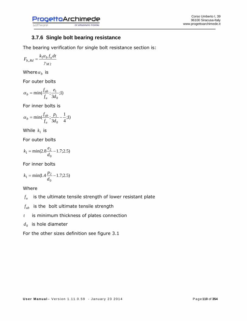
Corso Umberto I, 39 96100 Siracusa-Italy
www.progettoarchimede.it
U s e r M a n u a l – V e r s i o n 1 . 1 1 . 0 . 5 9 - J a n u a r y 2 3 2 0 1 4 P a g e 110 of 354
3.7.6 Single bolt bearing resistance
The bearing verification for single bolt resistance section is:
2
1,,
M
ubRdb
dtfkF
Where b is
For outer bolts
)1;3
;min(0
1
d
e
f
f
u
ubb
For inner bolts is
)1;4
1
3;min(
0
1 d
p
f
f
u
ubb
While 1k is
For outer bolts
)5.2;7.18.2min(0
21
d
ek
For inner bolts
)5.2;7.14.1min(0
21
d
pk
Where
uf is the ultimate tensile strength of lower resistant plate
ubf is the bolt ultimate tensile strength
t is minimum thickness of plates connection
0d is hole diameter
For the other sizes definition see figure 3.1
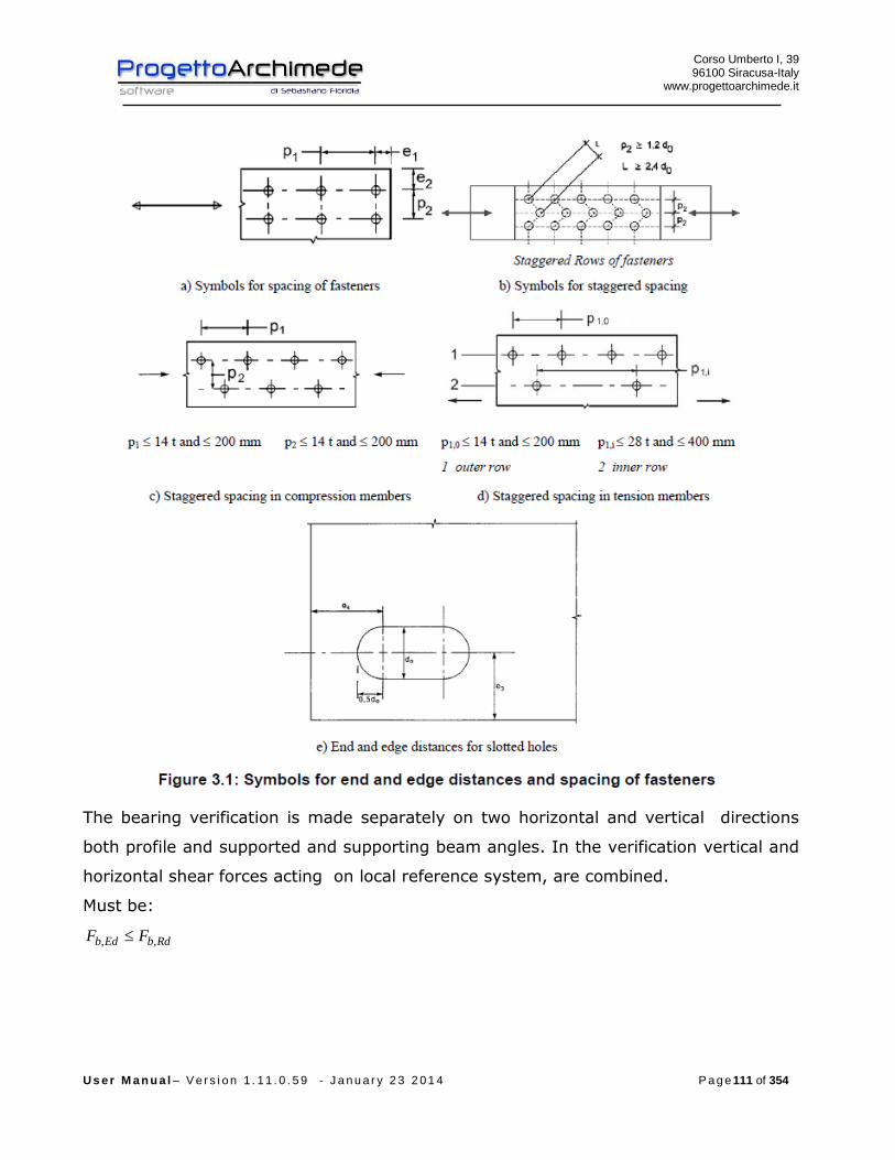
Corso Umberto I, 39 96100 Siracusa-Italy
www.progettoarchimede.it
U s e r M a n u a l – V e r s i o n 1 . 1 1 . 0 . 5 9 - J a n u a r y 2 3 2 0 1 4 P a g e 111 of 354
The bearing verification is made separately on two horizontal and vertical directions
both profile and supported and supporting beam angles. In the verification vertical and
horizontal shear forces acting on local reference system, are combined.
Must be:
RdbEdb FF ,,
Corso Umberto I, 39 96100 Siracusa-Italy
www.progettoarchimede.it
U s e r M a n u a l – V e r s i o n 1 . 1 1 . 0 . 5 9 - J a n u a r y 2 3 2 0 1 4 P a g e 112 of 354
3.7.7 Plate Connection in bending
Verification made in according with EC3 1-8 point 6.2.6.5
The design resistance and failure mode of a plate in bending, together with the
associated bolts in tension, should be taken as similar to those of an equivalent T-stub
(EC3 – 1-8 point 6.2.4), the design resistance for both:
- each individual bolt-row required to resist tension;
- each group of bolt-rows required to resist tension.
The group of bolt rows , both the reinforced sides connecting to the end plate should be
considered as an equivalent T-stub. In an extended end-plate, considered as the part
of the plate extended on the beam (extended end - plate), the bolt-row in the extended
part is considered as a separated T-stub equivalent, see Figure 6.10. The design
resistance and failure mode should be determined separately for each T-stub
equivalent.
The size mine (EC3 – 1-8 point 6.2.4) should be taken from Figure 6.8 for the beam
portion that is between the superior and inferior beam flange . For the end-plate
extension mine should be taken as xe , see Figure 6.10.
The effective length effl equivalent T-stub of plate should be determined in according
with EC3 – 1-8 point 6.2.4.2 using the values for each row bolts represented in the
table 6.6.
The values of m and xm to use for the Table 6.6 should be determined from
Figure 6.10.

Corso Umberto I, 39 96100 Siracusa-Italy
www.progettoarchimede.it
U s e r M a n u a l – V e r s i o n 1 . 1 1 . 0 . 5 9 - J a n u a r y 2 3 2 0 1 4 P a g e 113 of 354
To note as for the bolt rows between the superior and inferior beam flange the
effl is a vertical size so as the case of effl column flange
While for the extended end plate effl is an horizontal size.
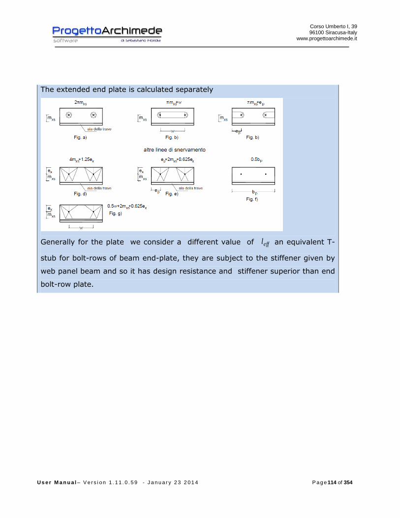
Corso Umberto I, 39 96100 Siracusa-Italy
www.progettoarchimede.it
U s e r M a n u a l – V e r s i o n 1 . 1 1 . 0 . 5 9 - J a n u a r y 2 3 2 0 1 4 P a g e 114 of 354
The extended end plate is calculated separately
Generally for the plate we consider a different value of effl an equivalent T-
stub for bolt-rows of beam end-plate, they are subject to the stiffener given by
web panel beam and so it has design resistance and stiffener superior than end
bolt-row plate.
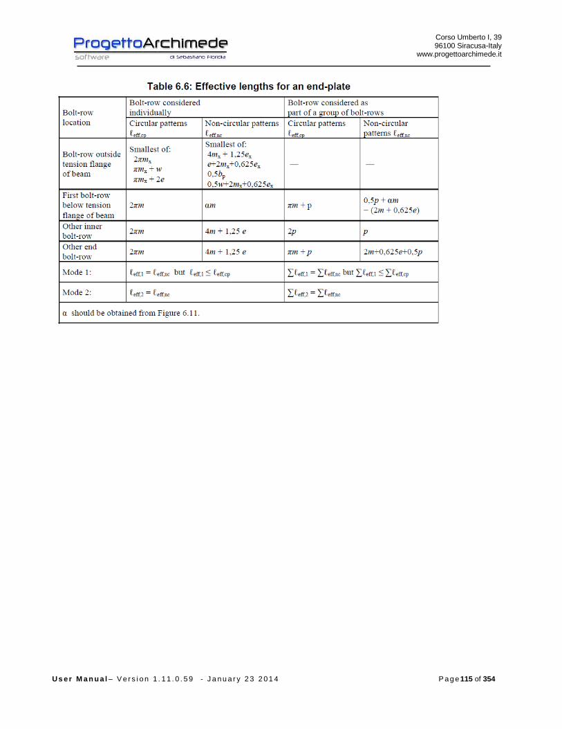
Corso Umberto I, 39 96100 Siracusa-Italy
www.progettoarchimede.it
U s e r M a n u a l – V e r s i o n 1 . 1 1 . 0 . 5 9 - J a n u a r y 2 3 2 0 1 4 P a g e 115 of 354
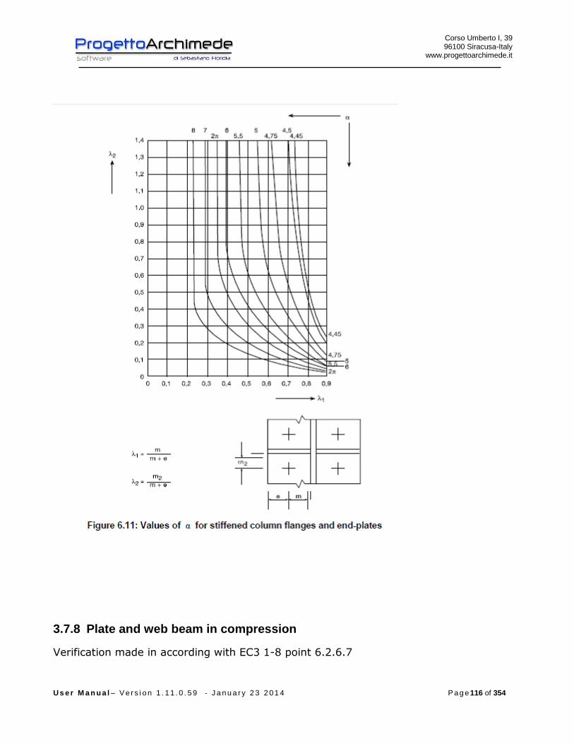
Corso Umberto I, 39 96100 Siracusa-Italy
www.progettoarchimede.it
U s e r M a n u a l – V e r s i o n 1 . 1 1 . 0 . 5 9 - J a n u a r y 2 3 2 0 1 4 P a g e 116 of 354
3.7.8 Plate and web beam in compression
Verification made in according with EC3 1-8 point 6.2.6.7
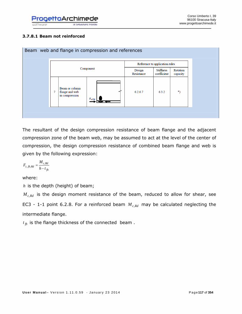
Corso Umberto I, 39 96100 Siracusa-Italy
www.progettoarchimede.it
U s e r M a n u a l – V e r s i o n 1 . 1 1 . 0 . 5 9 - J a n u a r y 2 3 2 0 1 4 P a g e 117 of 354
3.7.8.1 Beam not reinforced
Beam web and flange in compression and references
The resultant of the design compression resistance of beam flange and the adjacent
compression zone of the beam web, may be assumed to act at the level of the center of
compression, the design compression resistance of combined beam flange and web is
given by the following expression:
fb
RdcRdfbc
th
MF
,,,
where:
h is the depth (height) of beam;
RdcM , is the design moment resistance of the beam, reduced to allow for shear, see
EC3 - 1-1 point 6.2.8. For a reinforced beam RdcM , may be calculated neglecting the
intermediate flange.
fbt is the flange thickness of the connected beam .

Corso Umberto I, 39 96100 Siracusa-Italy
www.progettoarchimede.it
U s e r M a n u a l – V e r s i o n 1 . 1 1 . 0 . 5 9 - J a n u a r y 2 3 2 0 1 4 P a g e 118 of 354
Center of compression
If the depth (height) of the beam is more than 600 mm, the design resistance
compression beam contribution should be limited to 20%.
For the RdcM , calculation with shear force, see EC3-1-1 point 6.2.8, we use
reduced moment
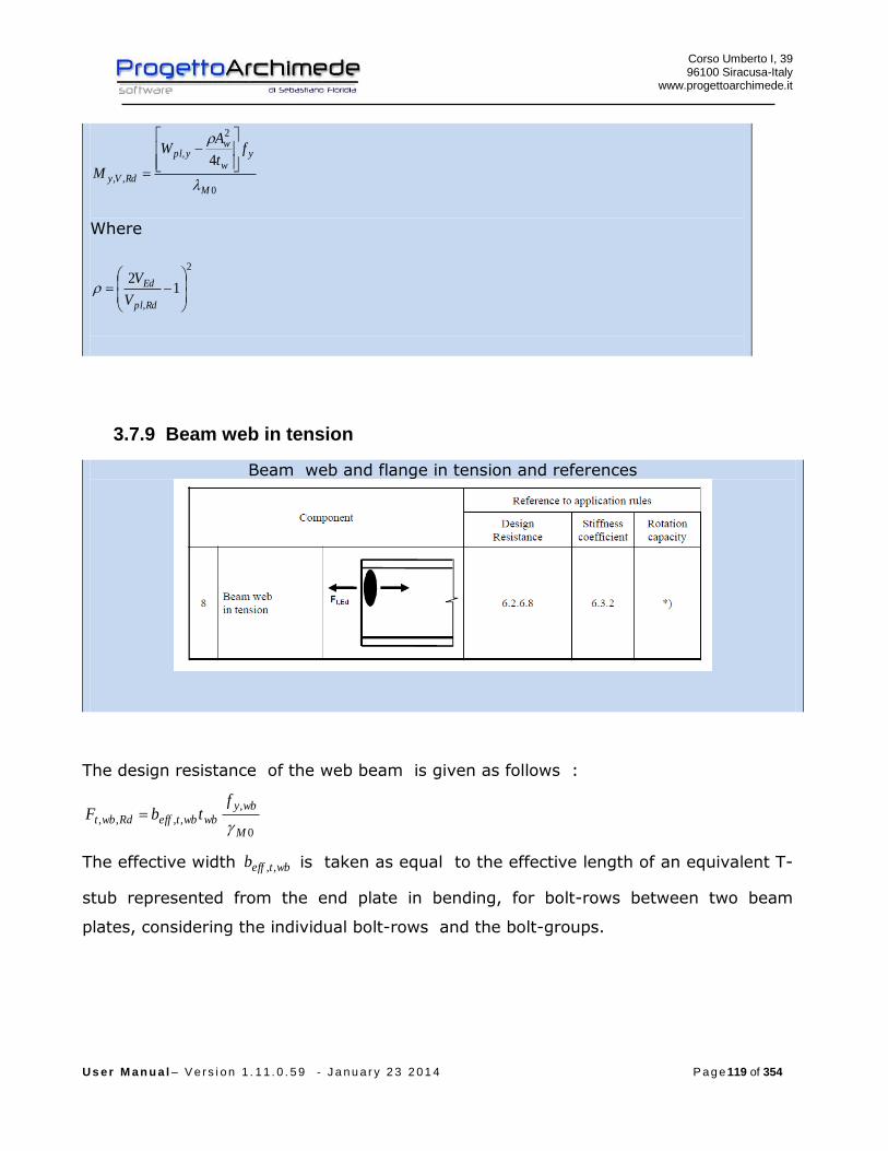
Corso Umberto I, 39 96100 Siracusa-Italy
www.progettoarchimede.it
U s e r M a n u a l – V e r s i o n 1 . 1 1 . 0 . 5 9 - J a n u a r y 2 3 2 0 1 4 P a g e 119 of 354
0
2
,
,,
4
M
yw
wypl
RdVy
ft
AW
M
Where
2
,
12
Rdpl
Ed
V
V
3.7.9 Beam web in tension
Beam web and flange in tension and references
The design resistance of the web beam is given as follows :
0
,
,,,,M
wby
wbwbteffRdwbt
ftbF
The effective width wbteffb ,, is taken as equal to the effective length of an equivalent T-
stub represented from the end plate in bending, for bolt-rows between two beam
plates, considering the individual bolt-rows and the bolt-groups.

Corso Umberto I, 39 96100 Siracusa-Italy
www.progettoarchimede.it
U s e r M a n u a l – V e r s i o n 1 . 1 1 . 0 . 5 9 - J a n u a r y 2 3 2 0 1 4 P a g e 120 of 354
3.7.10 Welding
Design resistance of fillet weld is:
lafF dvwRdw .,
Where
dvwf . is weld shear design resistance.
a is height throat weld.
l is length cordon weld.
The welding shear calculation resistance dvwf . is:
2.
3/
Mw
udvw
ff
where:
uf is nominal breaking resistance of the weakest node;
w is the appropriate correlation factor shown in Table 4.1.
The weld verification should be satisfied if:
Corso Umberto I, 39 96100 Siracusa-Italy
www.progettoarchimede.it
U s e r M a n u a l – V e r s i o n 1 . 1 1 . 0 . 5 9 - J a n u a r y 2 3 2 0 1 4 P a g e 121 of 354
RdwEdw FF ,,
where:
EdwF , is the force design value acting all over cordon weld;
RdwF , is the design resistance of all over weld cordon.
Below are summaries the action of calculation should be considered for the welds
verification.
3.7.10.1 Welds beam – connection plate to the column
The plate generally should be bending moment resistant and normal force, welding on
the plate should be checked when:
rdvwRdwEdbEdb
Edept bafFN
z
MF .,
,,,,
2 Where
rb is the length cordon weld on the tension or compressed beam area
The web beam generally should be shear resisting, the welding on the web should be
checked when:
rdvwRdwEdept hafFVF .,,,
Where
rh is length cordon weld on the web column
3.7.11 Joint design resistance due to axial force
Verification made in according with EC3 1-8 point 6.2.7.1
The design resistance for pure normal stress RdjN , is calculated as the less value of
single design resistance calculated for the joint ( first considered), if is compression
force or tension force.

Corso Umberto I, 39 96100 Siracusa-Italy
www.progettoarchimede.it
U s e r M a n u a l – V e r s i o n 1 . 1 1 . 0 . 5 9 - J a n u a r y 2 3 2 0 1 4 P a g e 122 of 354
3.7.11.1 Resistance of design Compression
The compression design resistance RdjN , is the smallest of following values:
- Column Web panel in transverse compression RdwccF ,,2
- Plate and beam web in compression bplN , ( plastic normal stress of the beam).
3.7.11.2 Design resistance in tension
The normal stress tension RdjN , of connection beam-column of a bolted joint with a
plate should be determined by:
RdtrrowRdj FnN ,,
where:
RdtrF , is the effective design resistance of tension of the bolt-row r ;
rown is the number of bolt-rows.
The effective design tension resistance RdtrF , for each row-bolt r, taken as single bolt-
rows, is the smaller design tension resistance for a single bolt-row of the following basic
components:
- Column Web in transverse tension RdwctF ,,
- the column flange in transverse bending RdfctF ,,,
- Connection end plate in bending RdeptF ,,,
- Web beam in tension RdwbtF ,,,
- Flange and web beam in tension bplN ,
3.7.12 Shear resistance
Verification made in according EC3 1-8 point 6.2.2
The shear force is totally transferred to the bolts, so the design shear resistance is
connected to the shear resistance.
For a shear connection of class A (EC3 1-8 point 3.4.1) the single bolt shear
resistance should be obtained:
Corso Umberto I, 39 96100 Siracusa-Italy
www.progettoarchimede.it
U s e r M a n u a l – V e r s i o n 1 . 1 1 . 0 . 5 9 - J a n u a r y 2 3 2 0 1 4 P a g e 123 of 354
2
,,M
ubvRdv
AfF
If the shear plane is through the thread bolt portion:
- for classes 4.6, 5.6 e 8.8
6.0v
- for classes 4.8, 5.8 e 10.9
5.0v
If the shear plane is through the not thread bolt portion:
6.0v
For the bolts of connection stressed in tension (see bolts in tension in the case of
bending) their resistance should be reduced by 4.1/4.0 , so:
4.1
4.0,,,,, RdtrvRdv FF
Where
2,,,
M
ubvRdtrv
AfF
is the shear bolt resistance stressed to tension too.
The shear resistance RdjV , of connection beam-column of a bolted joint with plate
should be determined by:
boltn
RdvRdj FV
1
,,
The bearing verification for single bolt is:
2
1,,
M
ubRdb
dtfkF
Where
For outer bolts
)1;3
;min(0
1
d
e
f
f
u
ubb
For inner bolts

Corso Umberto I, 39 96100 Siracusa-Italy
www.progettoarchimede.it
U s e r M a n u a l – V e r s i o n 1 . 1 1 . 0 . 5 9 - J a n u a r y 2 3 2 0 1 4 P a g e 124 of 354
)1;4
1
3;min(
0
1 d
p
f
f
u
ubb
For outer bolts
)5.2;7.18.2min(0
21
d
ek
For inner bolts
)5.2;7.14.1min(0
21
d
pk
Without shear force however should be considered a shear force equal to 2,5% of
the normal force of weaker section.
3.7.13 Bending force resistance
Verification made in according with EC3 1-8 point 6.2.7.2
The design moment resistance in bending of a bolted joint with an end plate
connection that has an individual bolt-row in tension (or if is considered only a bolt-row
in tension) should be calculated as shown in Figure 6.15 (c).
The design moment resistance of a bolted joint with a plate with more than tension
bolt-rows should be determined as shown in 6.2.7.2.
For compression center see Figure 6.15.

Corso Umberto I, 39 96100 Siracusa-Italy
www.progettoarchimede.it
U s e r M a n u a l – V e r s i o n 1 . 1 1 . 0 . 5 9 - J a n u a r y 2 3 2 0 1 4 P a g e 125 of 354

Corso Umberto I, 39 96100 Siracusa-Italy
www.progettoarchimede.it
U s e r M a n u a l – V e r s i o n 1 . 1 1 . 0 . 5 9 - J a n u a r y 2 3 2 0 1 4 P a g e 126 of 354
The moment of calculation should be taken as not less than a moment equal to 25% of
plastic moment of the weaker section, if the action is less.
The design moment resistance RdjM , f bolted joint beam- to-column with an end-
plate may be determined from:
r
RdtrrRdj FhM ,,
where:
RdtrF , is the effective design resistance of tension calculation of bolt-row r;
rh is the distance from bolt-row r from center of compression;
r is the bolt-row number.
NOTE: The bolt-rows are numerated from farther bolt-row from center of
compression.
The center of compression should be assumed to be in line with the center of the
compression flange of the connected member.
The effective design tension resistance RdtrF , for each bolt-row should be determined
in sequence, from bolt-rows number 1, that is from farther bolt-row from center of
compression, then proceeding to row 2, ecc.
When determining the effective design tension resistance RdtrF , of bolt-row r the
effective design tension resistance of all other bolt-rows closer to the center of
compression should be ignored.
The effective design tension resistance RdtrF , of each bolt-row r taken as an individual
bolt-row, should be taken as the smallest value of the design tension resistance RdtrF ,
for an individual bolt-row of the following basic components:

Corso Umberto I, 39 96100 Siracusa-Italy
www.progettoarchimede.it
U s e r M a n u a l – V e r s i o n 1 . 1 1 . 0 . 5 9 - J a n u a r y 2 3 2 0 1 4 P a g e 127 of 354
- The column web in transverse tension RdwctF ,,
- The column flange in transverse bending RdfctF ,,,
- The end-plate in bending RdeptF ,,,
- The beam web in tension RdwbtF ,,,
The effective design tension resistance RdtrF , , of bolt-row r, should ,if necessary, be
reduced below the value of RdtrF , to ensure that all bolt-rows up to and including bolt-
row r, the following conditions are satisfied:
- The total resistance design
Rdwp
Rdtr
VF
,
, ;
- The total design resistance RdtrF , does not exceed the smaller of:
- The design resistance of the column web in compression RdwccF ,,, ;
- The design resistance of the beam web in compression RdfbcF ,,, .
The effective design tension resistance RdtrF , , of bolt-row r, should ,if necessary, be
reduced below the value of RdtrF , , to ensure that the sum of the design resistances
taken for the bolt-rows up and including bolt-row r that form part of the same group of
bolt-rows, does not exceed the design resistance of that group as a whole.
This should be checked for the following basic components:
- The column web in transverse tension RdwctF ,,
- The column flange in transverse bending RdfctF ,,,
- The end-plate in bending RdeptF ,,,
- The beam web in tension RdwbtF ,,,
Corso Umberto I, 39 96100 Siracusa-Italy
www.progettoarchimede.it
U s e r M a n u a l – V e r s i o n 1 . 1 1 . 0 . 5 9 - J a n u a r y 2 3 2 0 1 4 P a g e 128 of 354
3.7.14 Resistance to buckling and tension-bending
Verification made in according EC3 1-8 point 6.2.7.1
If the axial force EdN on the beam exceed the 5% of the design resistance RdplN , , the
conservative domain should be used is:
1,
,
,
,
Rdj
Edj
Rdj
Edj
N
N
M
M

Corso Umberto I, 39 96100 Siracusa-Italy
www.progettoarchimede.it
U s e r M a n u a l – V e r s i o n 1 . 1 1 . 0 . 5 9 - J a n u a r y 2 3 2 0 1 4 P a g e 129 of 354
3.8 Joint 124 (Connection beam – circular section beam)
3.8.1 Forces
On the profiles can be applied the following forces:
EdN normal force (positive if tension force)
xEdV , horizontal shear
yEdV , vertical shear
xEdM , bending moment all round x axis
The forces can be inserted by Tekla Structures (except xEdV , ), by modeler Midas, by
text file or we can calculate the structure to restore resistance.
If the stresses from Tekla Structures are zero, the actions will have minimum value in
according with EC3 1-8 point 6.2.7.1 (13)
Corso Umberto I, 39 96100 Siracusa-Italy
www.progettoarchimede.it
U s e r M a n u a l – V e r s i o n 1 . 1 1 . 0 . 5 9 - J a n u a r y 2 3 2 0 1 4 P a g e 130 of 354
plEd NN 025.0
plyEd VV 025.0,
where the plastic resistances are referred to the column.

Corso Umberto I, 39 96100 Siracusa-Italy
www.progettoarchimede.it
U s e r M a n u a l – V e r s i o n 1 . 1 1 . 0 . 5 9 - J a n u a r y 2 3 2 0 1 4 P a g e 131 of 354
3.8.2 Geometric verification
The procedure provides to verify the construction requirements for drilling bolted
joint, in according with l’EC3 1-8 and the following table 3.3 and figure 3.1.
The verification is made only for e1 and e2, and not for p1 e p2 because the local
buckling resistance of the plate is always prevented by the stiffeners and by the same
column.

Corso Umberto I, 39 96100 Siracusa-Italy
www.progettoarchimede.it
U s e r M a n u a l – V e r s i o n 1 . 1 1 . 0 . 5 9 - J a n u a r y 2 3 2 0 1 4 P a g e 132 of 354
3.8.3 Design resistance of single bolt and single weld
In this paragraph we recall the common criteria for verification of single bolts and
single weld.
Corso Umberto I, 39 96100 Siracusa-Italy
www.progettoarchimede.it
U s e r M a n u a l – V e r s i o n 1 . 1 1 . 0 . 5 9 - J a n u a r y 2 3 2 0 1 4 P a g e 133 of 354
3.8.3.1 Design resistance at Bolt tensile force
The tension resistance of single bolt is:
2,
9.0
M
subRdt
AfF
Where
sA is stressed tensile area
ubf is the last tensile of bolt
3.8.3.2 Bolt shear design resistance
For a shear connection (see class A EC3 1-8 point 3.4.1) the single bolt shear strength
design (for a single resistant section) is:
2
,,M
ubvRdv
AfF
If the shear plane is through the threaded bolt portion:
- for the classes 4.6, 5.6 e 8.8
6.0v
- for the classes 4.8, 5.8 e 10.9
5.0v
If the shear plane is through not threaded bolt portion:
6.0v
While
A è is the bolt area
ubf is the last bolt tensile stress
3.8.3.3 Design resistance of the weld
Design resistance of fillet weld is:
lafF dvwRdw .,
Where
dvwf . is weld shear design resistance.

Corso Umberto I, 39 96100 Siracusa-Italy
www.progettoarchimede.it
U s e r M a n u a l – V e r s i o n 1 . 1 1 . 0 . 5 9 - J a n u a r y 2 3 2 0 1 4 P a g e 134 of 354
a is height throat weld.
l is cordon weld length.
The welding shear calculation resistance dvwf . is:
2.
3/
Mw
udvw
ff
where:
uf is nominal breaking resistance of the weakest node;
w is the appropriate correlation factor shown in Table 4.1.

Corso Umberto I, 39 96100 Siracusa-Italy
www.progettoarchimede.it
U s e r M a n u a l – V e r s i o n 1 . 1 1 . 0 . 5 9 - J a n u a r y 2 3 2 0 1 4 P a g e 135 of 354
3.8.4 Verifications made
The verifications made on the joint are the following:
- Flange and beam web in compression
RdfbcEdfbc FF ,,,,
Bearing resistance verification on two horizontal directions on the connection
RdbEdb FF ,,
- Verification beam web panel in shear
RdwpEdwp VV ,,
- Verification of web beam in compression
RdwccEdwcc FF ,,,,
- Verification axial force resistance without moment resistance applied
1,
,
Rdj
Edj
N
N
- Verification for shear force
1,
,
Rdj
Edj
V
V
Verification in bending without axial force applied
1,
,
Rdj
Edj
M
M
- Verification in buckling
1,
,
,
,
Rdj
Edj
Rdj
Edj
N
N
M
M
If the axial force EdN does not exceed the 5% of the plastic axial force RdplN , , is
neglected the coexistence of the axial force and the rule becomes
1,
,
Rdj
Edj
M
M

Corso Umberto I, 39 96100 Siracusa-Italy
www.progettoarchimede.it
U s e r M a n u a l – V e r s i o n 1 . 1 1 . 0 . 5 9 - J a n u a r y 2 3 2 0 1 4 P a g e 136 of 354
3.8.5 Bearing resistance of single bolt
The bearing verification for single bolt resistance section is:
2
1,,
M
ubRdb
dtfkF
Where b is
For outer bolts
)1;3
;min(0
1
d
e
f
f
u
ubb
For inner bolts is
)1;4
1
3;min(
0
1 d
p
f
f
u
ubb
While 1k is
For outer bolts
)5.2;7.18.2min(0
21
d
ek
For inner bolts is
)5.2;7.14.1min(0
21
d
pk
Where
uf is the ultimate tensile strength of lower resistant plate
ubf is the bolt ultimate tensile strength
t is minimum thickness of plates connection
0d is hole diameter
For the other sizes definition see figure 3.1

Corso Umberto I, 39 96100 Siracusa-Italy
www.progettoarchimede.it
U s e r M a n u a l – V e r s i o n 1 . 1 1 . 0 . 5 9 - J a n u a r y 2 3 2 0 1 4 P a g e 137 of 354
The bearing verification is made separately on two horizontal and vertical directions
both profile and supported and supporting beam angles. In the verification vertical and
horizontal shear forces acting on local reference system, are combined.
Must be:
RdbEdb FF ,,

Corso Umberto I, 39 96100 Siracusa-Italy
www.progettoarchimede.it
U s e r M a n u a l – V e r s i o n 1 . 1 1 . 0 . 5 9 - J a n u a r y 2 3 2 0 1 4 P a g e 138 of 354
3.8.6 Plate Connection in bending
Verification made in according with EC3 1-8 point 6.2.6.5
The design resistance and failure mode of a plate in bending, together with the
associated bolts in tension, should be taken as similar to those of an equivalent T-stub
(EC3 – 1-8 point 6.2.4), the design resistance for both:
- each individual bolt-row required to resist tension;
- each group of bolt-rows required to resist tension.
The group of bolt rows, both the reinforced sides connecting to the end plate should be
considered as an equivalent T-stub. In an extended end-plate, considered as the part
of the plate extended on the beam (extended end - plate), the bolt-row in the extended
part is considered as a separated T-stub equivalent, see Figure 6.10. The design
resistance and failure mode should be determined separately for each T-stub
equivalent.
The size mine (EC3 – 1-8 point 6.2.4) should be taken from Figure 6.8 for the beam
portion that is between the superior and inferior beam flange . For the end-plate
extension mine should be taken as xe , see Figure 6.10.
The effective length effl equivalent T-stub of plate should be determined in according
with EC3 – 1-8 point 6.2.4.2 using the values for each row bolts represented in the
table 6.6.
The values of m and xm to use for the Table 6.6 should be determined from
Figure 6.10.

Corso Umberto I, 39 96100 Siracusa-Italy
www.progettoarchimede.it
U s e r M a n u a l – V e r s i o n 1 . 1 1 . 0 . 5 9 - J a n u a r y 2 3 2 0 1 4 P a g e 139 of 354
To note as for the bolt rows between the superior and inferior beam flange the
effl is a vertical size so as the case of effl column flange
While for the extended end plate effl is an horizontal size.
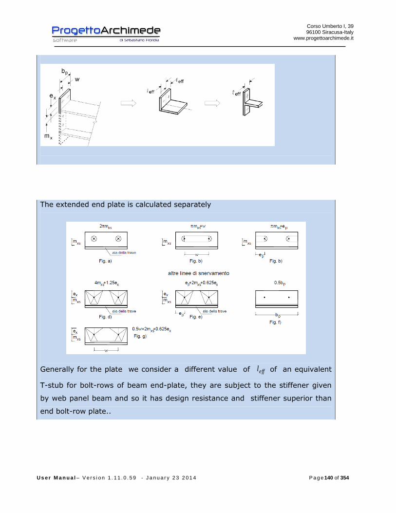
Corso Umberto I, 39 96100 Siracusa-Italy
www.progettoarchimede.it
U s e r M a n u a l – V e r s i o n 1 . 1 1 . 0 . 5 9 - J a n u a r y 2 3 2 0 1 4 P a g e 140 of 354
The extended end plate is calculated separately
Generally for the plate we consider a different value of effl of an equivalent
T-stub for bolt-rows of beam end-plate, they are subject to the stiffener given
by web panel beam and so it has design resistance and stiffener superior than
end bolt-row plate..

Corso Umberto I, 39 96100 Siracusa-Italy
www.progettoarchimede.it
U s e r M a n u a l – V e r s i o n 1 . 1 1 . 0 . 5 9 - J a n u a r y 2 3 2 0 1 4 P a g e 141 of 354
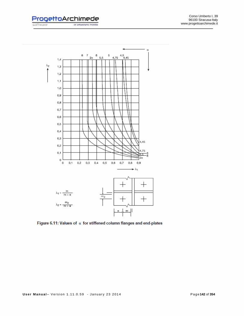
Corso Umberto I, 39 96100 Siracusa-Italy
www.progettoarchimede.it
U s e r M a n u a l – V e r s i o n 1 . 1 1 . 0 . 5 9 - J a n u a r y 2 3 2 0 1 4 P a g e 142 of 354

Corso Umberto I, 39 96100 Siracusa-Italy
www.progettoarchimede.it
U s e r M a n u a l – V e r s i o n 1 . 1 1 . 0 . 5 9 - J a n u a r y 2 3 2 0 1 4 P a g e 143 of 354
3.8.7 Plate and web beam in compression
Verification made in according with EC3 1-8 point 6.2.6.7
3.8.7.1 Beam not reinforced
Beam web and flange in compression and references
The resultant of the design compression resistance of beam flange and the adjacent
compression zone of the beam web, may be assumed to act at the level of the center of
compression, the design compression resistance of combined beam flange and web is
given by the following expression:
fb
RdcRdfbc
th
MF
,,,
where:
h is the depth (height) of beam;
RdcM , is the design moment resistance of the beam, reduced to allow for shear, see
EC3 - 1-1 point 6.2.8. For a reinforced beam RdcM , may be calculated neglecting the
intermediate flange.
fbt is the flange thickness of the connected beam.
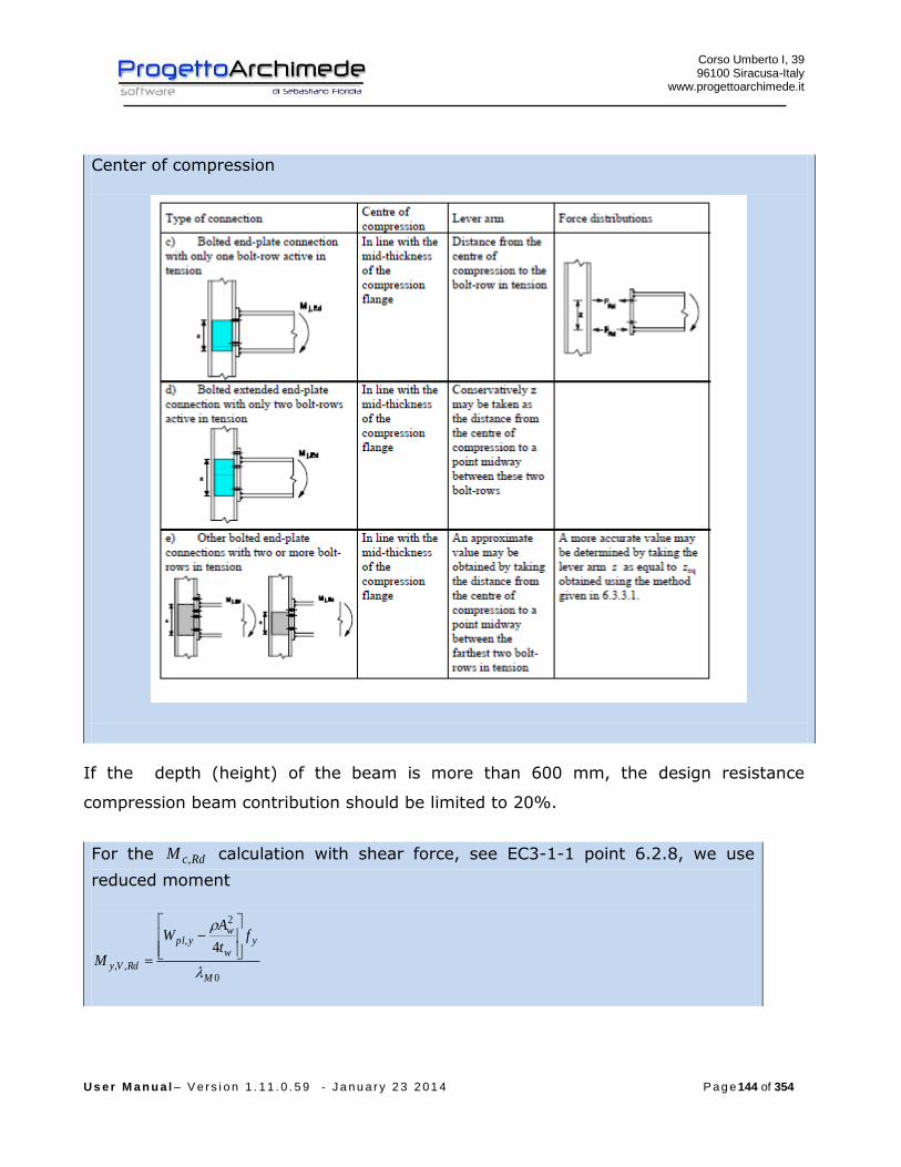
Corso Umberto I, 39 96100 Siracusa-Italy
www.progettoarchimede.it
U s e r M a n u a l – V e r s i o n 1 . 1 1 . 0 . 5 9 - J a n u a r y 2 3 2 0 1 4 P a g e 144 of 354
Center of compression
If the depth (height) of the beam is more than 600 mm, the design resistance
compression beam contribution should be limited to 20%.
For the RdcM , calculation with shear force, see EC3-1-1 point 6.2.8, we use
reduced moment
0
2
,
,,
4
M
yw
wypl
RdVy
ft
AW
M

Corso Umberto I, 39 96100 Siracusa-Italy
www.progettoarchimede.it
U s e r M a n u a l – V e r s i o n 1 . 1 1 . 0 . 5 9 - J a n u a r y 2 3 2 0 1 4 P a g e 145 of 354
Where
2
,
12
Rdpl
Ed
V
V
3.8.8 Beam web in tension
Verification made in according with EC3 1-8 point 6.2.6.8
Beam web and flange in tension and references
The design resistance of the web beam is given as follows :
0
,
,,,,M
wby
wbwbteffRdwbt
ftbF
The effective width wbteffb ,, is taken as equal to the effective length of an equivalent T-
stub represented from the end plate in bending, for bolt-rows between two beam
plates, considering the individual bolt-rows and the bolt-groups.

Corso Umberto I, 39 96100 Siracusa-Italy
www.progettoarchimede.it
U s e r M a n u a l – V e r s i o n 1 . 1 1 . 0 . 5 9 - J a n u a r y 2 3 2 0 1 4 P a g e 146 of 354
3.8.9 Welding
Design resistance of fillet weld
Where is:
lafF dvwRdw .,
dvwf . is weld shear design resistance.
a is height throat weld.
l is length cordon weld.
The welding shear calculation resistance dvwf . is:
2.
3/
Mw
udvw
ff
where:
uf is nominal breaking resistance of the weakest node;
w is the appropriate correlation factor shown in Table 4.1.
The weld verification should be satisfied if:

Corso Umberto I, 39 96100 Siracusa-Italy
www.progettoarchimede.it
U s e r M a n u a l – V e r s i o n 1 . 1 1 . 0 . 5 9 - J a n u a r y 2 3 2 0 1 4 P a g e 147 of 354
RdwEdw FF ,,
where:
EdwF , is the force design value acting all over cordon weld;
RdwF , is the design resistance of all over weld cordon.
Below are summaries the action of calculation should be considered for the welds
verification.
3.8.9.1 Welds beam – connection plate to the column
The plate generally should be bending moment resistant and normal force, welding on
the plate should be checked when:
rdvwRdwEdbEdb
Edept bafFN
z
MF .,
,,,,
2 Where
rb is the length cordon weld on the tension or compressed beam area
The web beam generally should be shear resisting, the welding on the web should be
checked when:
rdvwRdwEdept hafFVF .,,,
Where
rh is length cordon weld on the web column
3.8.10 Joint design resistance due to axial force
Verification made in according with EC3 1-8 point 6.2.7.1
The design resistance for pure normal stress RdjN , is calculated as the less value of
single design resistance calculated for the joint ( first considered), if is compression
force or tension force.

Corso Umberto I, 39 96100 Siracusa-Italy
www.progettoarchimede.it
U s e r M a n u a l – V e r s i o n 1 . 1 1 . 0 . 5 9 - J a n u a r y 2 3 2 0 1 4 P a g e 148 of 354
3.8.10.1 Resistance of design compression
The compression design resistance RdjN , is the smallest of following values:
- Column Web panel in transverse compression RdwccF ,,2
- Plate and beam web in compression bplN , ( plastic normal stress of the beam).
3.8.10.2 Design resistance in tension
The normal stress tension RdjN , of connection beam-column of a bolted joint with a
plate should be determined by:
RdtrrowRdj FnN ,,
where:
RdtrF , is the effective design resistance of tension of the bolt-row r;
rown is the number of bolt-rows.
The effective design tension resistance RdtrF , for each row-bolt r, taken as single bolt-
rows, is the smaller design tension resistance for a single bolt-row of the following basic
components:
- Column Web in transverse tension RdwctF ,,
- the column flange in transverse bending RdfctF ,,,
- Connection end plate in bending RdeptF ,,,
- Web beam in tension RdwbtF ,,,
- Flange and web beam in tension bplN ,
3.8.11 Shear resistance
Verification made in according EC3 1-8 point 6.2.2
The shear force is totally transferred to the bolts, so the design shear resistance is
connected to the shear resistance.
For a shear connection of class A (EC3 1-8 point 3.4.1) the single bolt shear
resistance should be obtained:
Corso Umberto I, 39 96100 Siracusa-Italy
www.progettoarchimede.it
U s e r M a n u a l – V e r s i o n 1 . 1 1 . 0 . 5 9 - J a n u a r y 2 3 2 0 1 4 P a g e 149 of 354
2
,,M
ubvRdv
AfF
If the shear plane is through the thread bolt portion:
- for the classes 4.6, 5.6 e 8.8
6.0v
- for the classes 4.8, 5.8 e 10.9
5.0v
If the shear plane is through the not thread bolt portion:
6.0v
For the bolts of connection stressed in tension (see bolts in tension in the case of
bending) their resistance should be reduced by 4.1/4.0 , so:
4.1
4.0,,,,, RdtrvRdv FF
Where
2,,,
M
ubvRdtrv
AfF
is the shear bolt resistance stressed to tension too.
The shear resistance RdjV , of connection beam-column of a bolted joint with plate
should be determined by:
boltn
RdvRdj FV
1
,,
The bearing verification for single bolt is:
2
1,,
M
ubRdb
dtfkF
Where
For outer bolts
)1;3
;min(0
1
d
e
f
f
u
ubb
for inner bolts

Corso Umberto I, 39 96100 Siracusa-Italy
www.progettoarchimede.it
U s e r M a n u a l – V e r s i o n 1 . 1 1 . 0 . 5 9 - J a n u a r y 2 3 2 0 1 4 P a g e 150 of 354
)1;4
1
3;min(
0
1 d
p
f
f
u
ubb
for outer bolts
)5.2;7.18.2min(0
21
d
ek
for inner bolts
)5.2;7.14.1min(0
21
d
pk
Without shear force however should be considered a shear force equal to 2,5% of
the normal force of weaker section.
3.8.12 Bending force resistance
The design moment resistance in bending of a bolted joint with an end plate
connection that has an individual bolt-row in tension (or if is considered only a bolt-row
in tension) should be calculated as shown in Figure 6.15 (c).
The design moment resistance of a bolted joint with a plate with more than tension
bolt-rows should be determined as shown in 6.2.7.2.
For compression center see Figure 6.15.

Corso Umberto I, 39 96100 Siracusa-Italy
www.progettoarchimede.it
U s e r M a n u a l – V e r s i o n 1 . 1 1 . 0 . 5 9 - J a n u a r y 2 3 2 0 1 4 P a g e 151 of 354
Corso Umberto I, 39 96100 Siracusa-Italy
www.progettoarchimede.it
U s e r M a n u a l – V e r s i o n 1 . 1 1 . 0 . 5 9 - J a n u a r y 2 3 2 0 1 4 P a g e 152 of 354
The moment of calculation should be taken as not less than a moment equal to 25% of
plastic moment of the weaker section, if the action is less.
The design moment resistance RdjM , f bolted joint beam- to-column with an end-
plate may be determined from:
r
RdtrrRdj FhM ,,
where:
RdtrF , is the effective design resistance of tension calculation of bolt-row r;
rh is the distance from bolt-row r from center of compression;
r is the bolt-row number.
NOTE: The bolt-rows are numerated from farther bolt-row from center of
compression.
The center of compression should be assumed to be in line with the center of the
compression flange of the connected member.
The effective design tension resistance RdtrF , for each bolt-row should be determined
in sequence, from bolt-rows number 1, that is from farther bolt-row from center of
compression, then proceeding to row 2, ecc.
When determining the effective design tension resistance RdtrF , of bolt-row r the
effective design tension resistance of all other bolt-rows closer to the center of
compression should be ignored.
The effective design tension resistance RdtrF , of each bolt-row r taken as an individual
bolt-row, should be taken as the smallest value of the design tension resistance RdtrF ,
for an individual bolt-row of the following basic components:

Corso Umberto I, 39 96100 Siracusa-Italy
www.progettoarchimede.it
U s e r M a n u a l – V e r s i o n 1 . 1 1 . 0 . 5 9 - J a n u a r y 2 3 2 0 1 4 P a g e 153 of 354
- The column web in transverse tension RdwctF ,,
- The column flange in transverse bending RdfctF ,,,
- The end-plate in bending RdeptF ,,,
- The beam web in tension RdwbtF ,,,
The effective design tension resistance RdtrF , , of bolt-row r, should ,if necessary, be
reduced below the value of RdtrF , to ensure that all bolt-rows up to and including bolt-
row r, the following conditions are satisfied:
- The total design resistance
Rdwp
Rdtr
VF
,
, ;
- The total design resistance RdtrF , does not exceed the smaller of:
- The design resistance of the column web in compression RdwccF ,,, ;
- The design resistance of the beam web in compression RdfbcF ,,, .
The effective design tension resistance RdtrF , , of bolt-row r , should ,if necessary, be
reduced below the value of RdtrF , , to ensure that the sum of the design resistances
taken for the bolt-rows up and including bolt-row r that form part of the same group of
bolt-rows, does not exceed the design resistance of that group as a whole.
This should be checked for the following basic components:
- The column web in transverse tension RdwctF ,,
- The column flange in transverse bending RdfctF ,,,
- The end-plate in bending RdeptF ,,,
- The beam web in tension RdwbtF ,,,

Corso Umberto I, 39 96100 Siracusa-Italy
www.progettoarchimede.it
U s e r M a n u a l – V e r s i o n 1 . 1 1 . 0 . 5 9 - J a n u a r y 2 3 2 0 1 4 P a g e 154 of 354
3.8.13 Resistance to buckling and tension-bending
Verification made in according EC3 1-8 point 6.2.7.1
If the axial force EdN on the beam exceed the 5% of the design resistance RdplN , , the
conservative domain should be used is:
1,
,
,
,
Rdj
Edj
Rdj
Edj
N
N
M
M

Corso Umberto I, 39 96100 Siracusa-Italy
www.progettoarchimede.it
U s e r M a n u a l – V e r s i o n 1 . 1 1 . 0 . 5 9 - J a n u a r y 2 3 2 0 1 4 P a g e 155 of 354
3.9 Joint 128 (Beam web – Column plate welded)
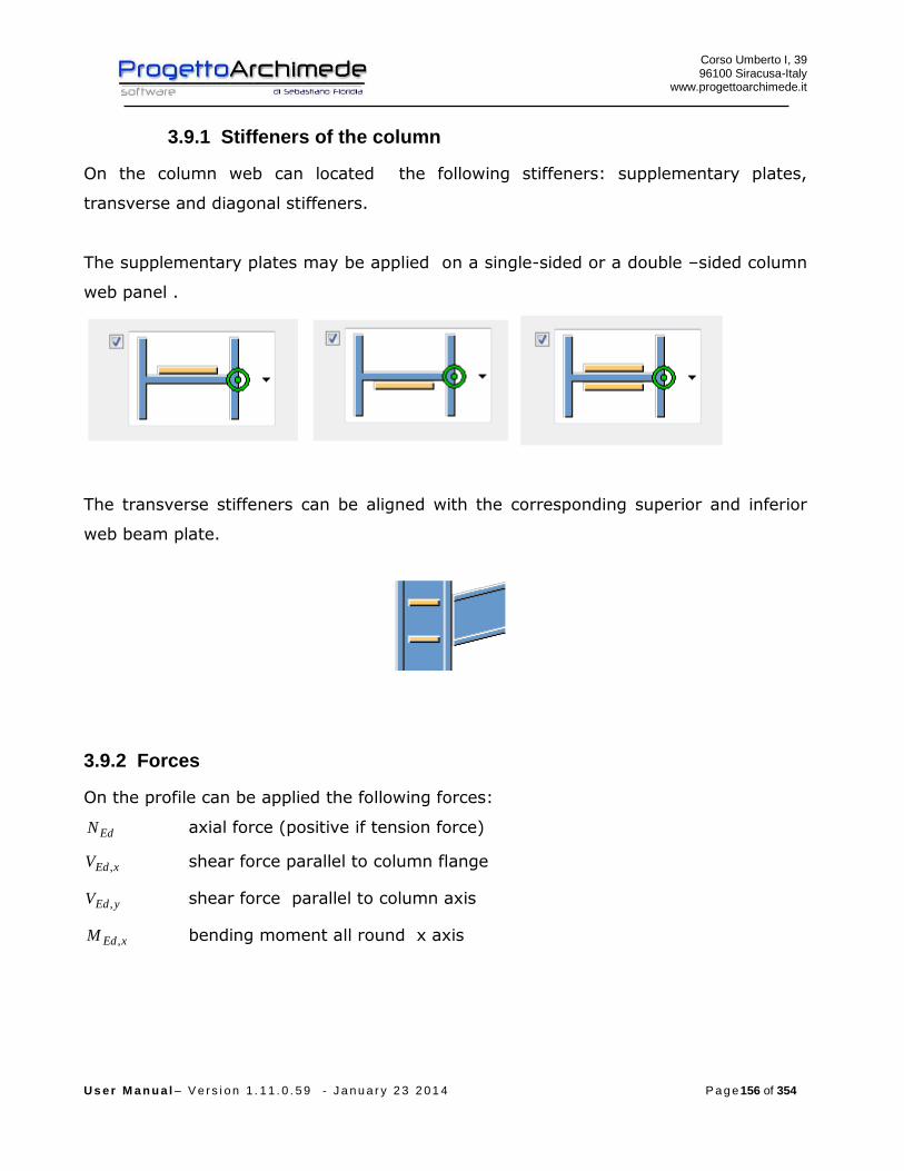
Corso Umberto I, 39 96100 Siracusa-Italy
www.progettoarchimede.it
U s e r M a n u a l – V e r s i o n 1 . 1 1 . 0 . 5 9 - J a n u a r y 2 3 2 0 1 4 P a g e 156 of 354
3.9.1 Stiffeners of the column
On the column web can located the following stiffeners: supplementary plates,
transverse and diagonal stiffeners.
The supplementary plates may be applied on a single-sided or a double –sided column
web panel .
The transverse stiffeners can be aligned with the corresponding superior and inferior
web beam plate.
3.9.2 Forces
On the profile can be applied the following forces:
EdN axial force (positive if tension force)
xEdV , shear force parallel to column flange
yEdV , shear force parallel to column axis
xEdM , bending moment all round x axis
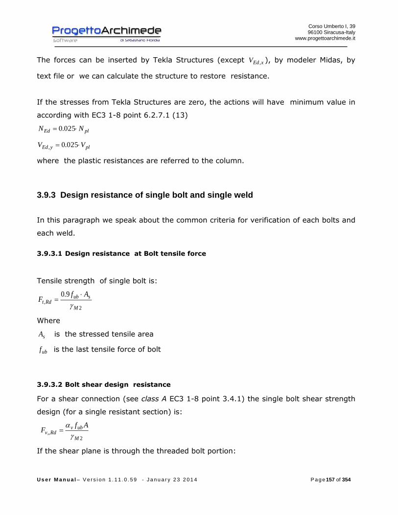
Corso Umberto I, 39 96100 Siracusa-Italy
www.progettoarchimede.it
U s e r M a n u a l – V e r s i o n 1 . 1 1 . 0 . 5 9 - J a n u a r y 2 3 2 0 1 4 P a g e 157 of 354
The forces can be inserted by Tekla Structures (except xEdV , ), by modeler Midas, by
text file or we can calculate the structure to restore resistance.
If the stresses from Tekla Structures are zero, the actions will have minimum value in
according with EC3 1-8 point 6.2.7.1 (13)
plEd NN 025.0
plyEd VV 025.0,
where the plastic resistances are referred to the column.
3.9.3 Design resistance of single bolt and single weld
In this paragraph we speak about the common criteria for verification of each bolts and
each weld.
3.9.3.1 Design resistance at Bolt tensile force
Tensile strength of single bolt is:
2,
9.0
M
subRdt
AfF
Where
sA is the stressed tensile area
ubf is the last tensile force of bolt
3.9.3.2 Bolt shear design resistance
For a shear connection (see class A EC3 1-8 point 3.4.1) the single bolt shear strength
design (for a single resistant section) is:
2
,,M
ubvRdv
AfF
If the shear plane is through the threaded bolt portion:
Corso Umberto I, 39 96100 Siracusa-Italy
www.progettoarchimede.it
U s e r M a n u a l – V e r s i o n 1 . 1 1 . 0 . 5 9 - J a n u a r y 2 3 2 0 1 4 P a g e 158 of 354
- for the classes 4.6, 5.6 e 8.8
6.0v
- for the classes 4.8, 5.8 e 10.9
5.0v
If the shear plane is through the not threaded bolt portion:
6.0v
While
A is the bolt area
ubf is the last bolt tensile stress
3.9.3.3 Design resistance of the weld
Design resistance of fillet weld is:
lafF dvwRdw .,
Dove
dvwf . is weld shear design resistance.
a is the height throat of the weld.
l is the length cordon of the weld.
The welding shear calculation resistance dvwf . is:
2.
3/
Mw
udvw
ff
where:
uf is nominal breaking resistance of the weakest node;
w is the appropriate correlation factor shown in Table 4.1.
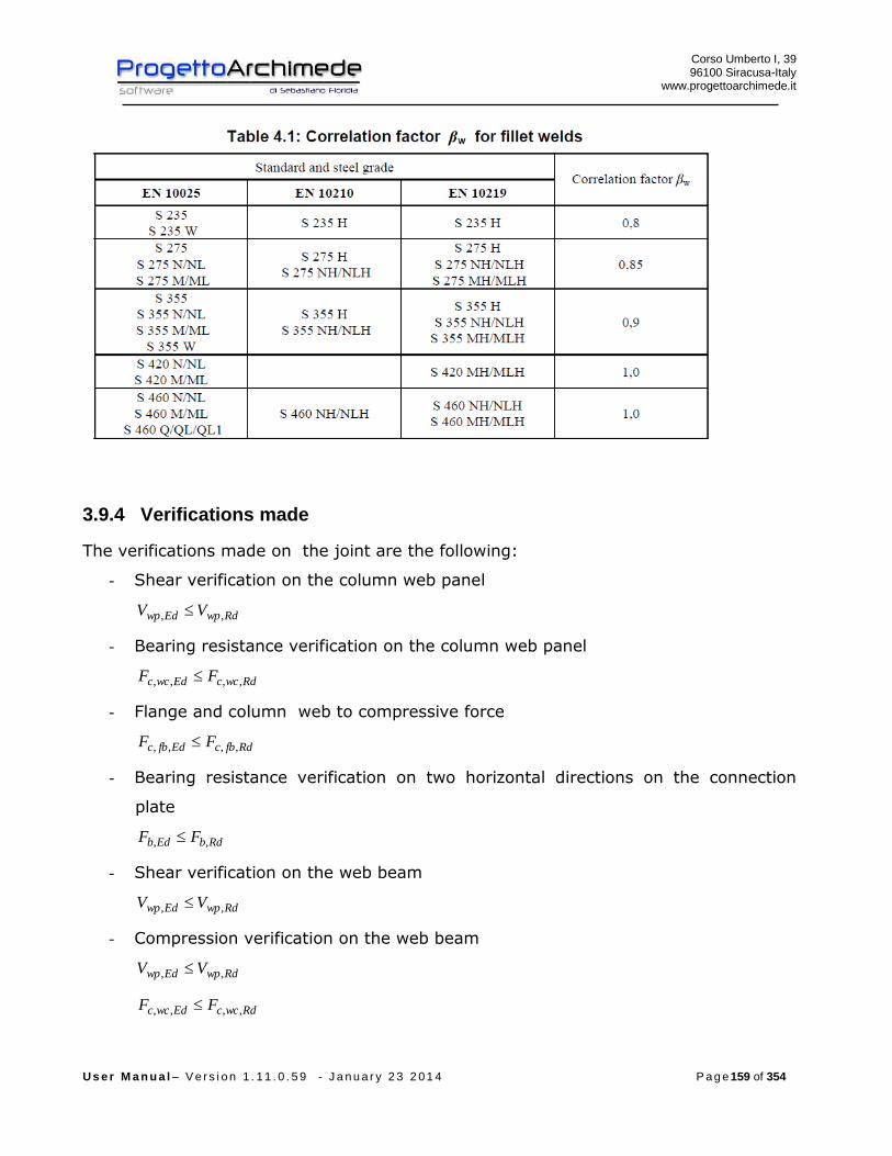
Corso Umberto I, 39 96100 Siracusa-Italy
www.progettoarchimede.it
U s e r M a n u a l – V e r s i o n 1 . 1 1 . 0 . 5 9 - J a n u a r y 2 3 2 0 1 4 P a g e 159 of 354
3.9.4 Verifications made
The verifications made on the joint are the following:
- Shear verification on the column web panel
RdwpEdwp VV ,,
- Bearing resistance verification on the column web panel
RdwccEdwcc FF ,,,,
- Flange and column web to compressive force
RdfbcEdfbc FF ,,,,
- Bearing resistance verification on two horizontal directions on the connection
plate
RdbEdb FF ,,
- Shear verification on the web beam
RdwpEdwp VV ,,
- Compression verification on the web beam
RdwpEdwp VV ,,
RdwccEdwcc FF ,,,,

Corso Umberto I, 39 96100 Siracusa-Italy
www.progettoarchimede.it
U s e r M a n u a l – V e r s i o n 1 . 1 1 . 0 . 5 9 - J a n u a r y 2 3 2 0 1 4 P a g e 160 of 354
- Verification of axial force without moment resistance applied
1,
,
Rdj
Edj
N
N
- Shear force verification
1,
,
Rdj
Edj
V
V
- Bending force verification without axial force
1,
,
Rdj
Edj
M
M
- Buckling verififcation
1,
,
,
,
Rdj
Edj
Rdj
Edj
N
N
M
M
If the axial force EdN does not exceed the 5% of the plastic axial force RdplN , , is
neglected the coexistence of the axial force and the rule becomes
1,
,
Rdj
Edj
M
M
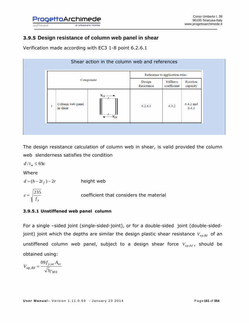
Corso Umberto I, 39 96100 Siracusa-Italy
www.progettoarchimede.it
U s e r M a n u a l – V e r s i o n 1 . 1 1 . 0 . 5 9 - J a n u a r y 2 3 2 0 1 4 P a g e 161 of 354
3.9.5 Design resistance of column web panel in shear
Verification made according with EC3 1-8 point 6.2.6.1
Shear action in the column web and references
The design resistance calculation of column web in shear, is valid provided the column
web slenderness satisfies the condition
69/ wtd
Where
rthd f 2)2( height web
yf
235 coefficient that considers the material
3.9.5.1 Unstiffened web panel column
For a single –sided joint (single-sided-joint), or for a double-sided joint (double-sided-
joint) joint which the depths are similar the design plastic shear resistance RdwpV , of an
unstiffened column web panel, subject to a design shear force EdwpV , , should be
obtained using:
0
,
,3
09
M
vcwcy
Rdwp
AfV
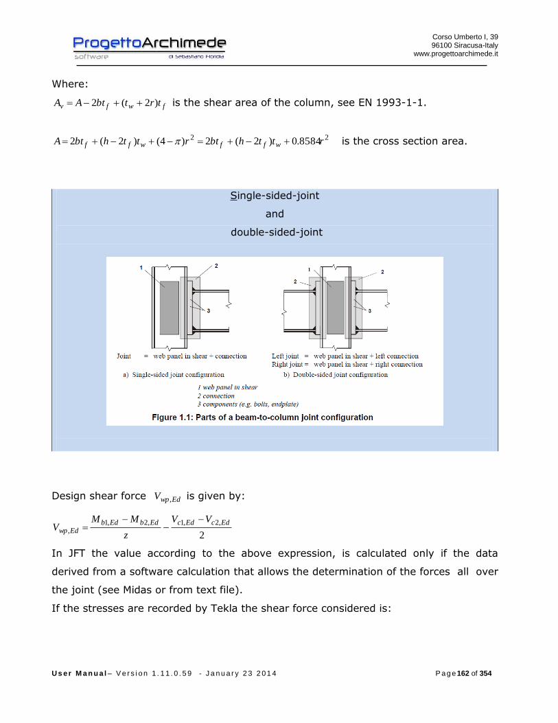
Corso Umberto I, 39 96100 Siracusa-Italy
www.progettoarchimede.it
U s e r M a n u a l – V e r s i o n 1 . 1 1 . 0 . 5 9 - J a n u a r y 2 3 2 0 1 4 P a g e 162 of 354
Where:
fwfv trtbtAA )2(2 is the shear area of the column, see EN 1993-1-1.
22 8584.0)2(2)4()2(2 rtthbtrtthbtA wffwff
is the cross section area.
Single-sided-joint
and
double-sided-joint
Design shear force EdwpV , is given by:
2
,2,1,2,1,
EdcEdcEdbEdbEdwp
VV
z
MMV
In JFT the value according to the above expression, is calculated only if the data
derived from a software calculation that allows the determination of the forces all over
the joint (see Midas or from text file).
If the stresses are recorded by Tekla the shear force considered is:
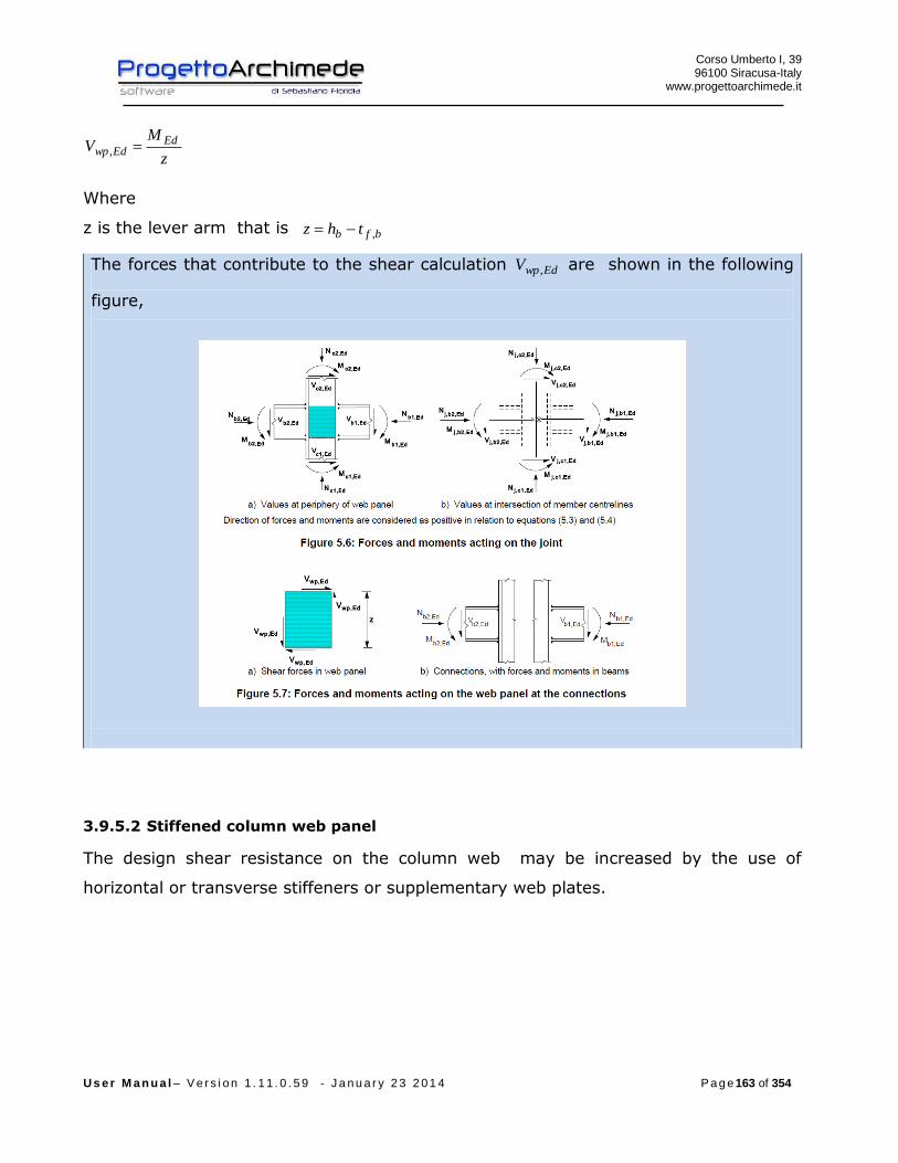
Corso Umberto I, 39 96100 Siracusa-Italy
www.progettoarchimede.it
U s e r M a n u a l – V e r s i o n 1 . 1 1 . 0 . 5 9 - J a n u a r y 2 3 2 0 1 4 P a g e 163 of 354
z
MV Ed
Edwp ,
Where
z is the lever arm that is bfb thz ,
The forces that contribute to the shear calculation EdwpV , are shown in the following
figure,
3.9.5.2 Stiffened column web panel
The design shear resistance on the column web may be increased by the use of
horizontal or transverse stiffeners or supplementary web plates.
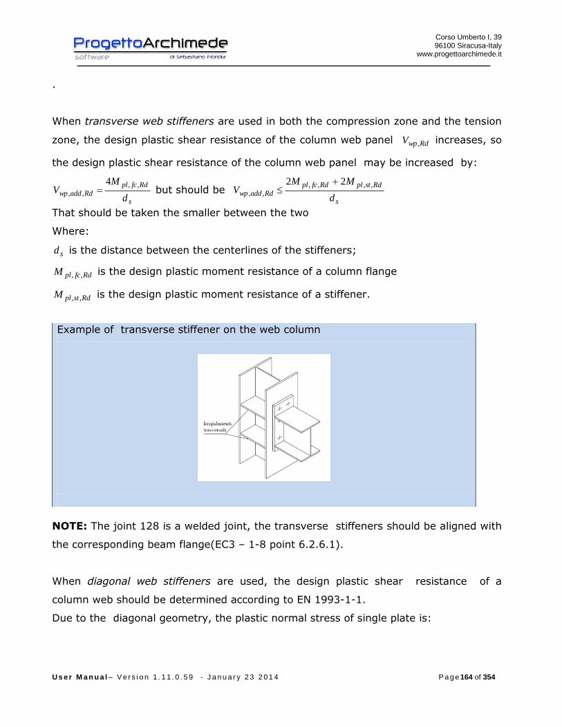
Corso Umberto I, 39 96100 Siracusa-Italy
www.progettoarchimede.it
U s e r M a n u a l – V e r s i o n 1 . 1 1 . 0 . 5 9 - J a n u a r y 2 3 2 0 1 4 P a g e 164 of 354
.
When transverse web stiffeners are used in both the compression zone and the tension
zone, the design plastic shear resistance of the column web panel RdwpV , increases, so
the design plastic shear resistance of the column web panel may be increased by:
s
Rdfcpl
Rdaddwpd
MV
,,
,,
4 but should be
s
RdstplRdfcpl
Rdaddwpd
MMV
,,,,
,,
22
That should be taken the smaller between the two
Where:
sd is the distance between the centerlines of the stiffeners;
RdfcplM ,, is the design plastic moment resistance of a column flange
RdstplM ,, is the design plastic moment resistance of a stiffener.
Example of transverse stiffener on the web column
NOTE: The joint 128 is a welded joint, the transverse stiffeners should be aligned with
the corresponding beam flange(EC3 – 1-8 point 6.2.6.1).
When diagonal web stiffeners are used, the design plastic shear resistance of a
column web should be determined according to EN 1993-1-1.
Due to the diagonal geometry, the plastic normal stress of single plate is:

Corso Umberto I, 39 96100 Siracusa-Italy
www.progettoarchimede.it
U s e r M a n u a l – V e r s i o n 1 . 1 1 . 0 . 5 9 - J a n u a r y 2 3 2 0 1 4 P a g e 165 of 354
0
,
,
diagydiag
diagpl
fAN
That should be greater than the force transmitted from the beam plate
cos/,z
MN Ed
diagpl
Where
EdM is the design moment transmitted from a single beam
c
b
h
harctan is the angle that the diagonal forms with the axis parallel to the beam
flange
cb hh e are respectively the beam width and the length column
The design shear resistance of column web panel RdwpV , may be increased by:
cos,,, diagplRdaddwp NV
Example of diagonal stiffener on the web column
If the column web is reinforced by adding a supplementary web plate, see Figure 6.5,
the shear area vcwA may be increased by di wcstb . If a further supplementary web plate
is added on the other side of the web column, no further increase of the shear area
should be made.

Corso Umberto I, 39 96100 Siracusa-Italy
www.progettoarchimede.it
U s e r M a n u a l – V e r s i o n 1 . 1 1 . 0 . 5 9 - J a n u a r y 2 3 2 0 1 4 P a g e 166 of 354
NOTE: The Weldability at the corner should be taken into account for a correct
modeling of reinforcement with supplementary web plate.
The supplementary web plate on the column web increase the rotational
stiffness of a joint, increasing the stiffness column web in shear , in compression
or in tension (EC3 - 6.3.2 (1).
The supplementary web plate should comply the following mechanical and geometrical
in according with EC3:
- The steel grade of the supplementary web plate should be equal to that of the
column;
- The width sb should be such that the supplementary web plate extends at least
to the toe of the root radius with of plate column or of the weld (fig. 6.5);
- The length sl should be such that the supplementary web plate extends
throughout the effective width of the web in tension and compression, see Figure
6.5;
The thickness st of the supplementary web plate should be not less than the column
web thickness wct .

Corso Umberto I, 39 96100 Siracusa-Italy
www.progettoarchimede.it
U s e r M a n u a l – V e r s i o n 1 . 1 1 . 0 . 5 9 - J a n u a r y 2 3 2 0 1 4 P a g e 167 of 354
The welds between the supplementary web plate and profile should be designed to
resist the applied design forces EdwpV , .
The width sb of a supplementary web plate should be less than st40 .
Discontinuous welds may be used in not corrosive environments.
The increase of the resistances on the web are cumulative.
The local verification should be satisfied if:
RdwpEdwp VV ,,
3.9.6 Resistance of column web in transverse compression
Verification made in according with EC3 1-8 point 6.2.6.2
Web column subject to compression and references
3.9.6.1 Unstiffened column web panel
The design resistance of an unstiffened column web subject to transverse compression
should be determined from:

Corso Umberto I, 39 96100 Siracusa-Italy
www.progettoarchimede.it
U s e r M a n u a l – V e r s i o n 1 . 1 1 . 0 . 5 9 - J a n u a r y 2 3 2 0 1 4 P a g e 168 of 354
0
,.,,,
M
wcywcwcceffwcRdwcc
ftbkF
but
1
,.,,,
M
wcywcwcceffwcRdwcc
ftbkF
It is considered as resistance of column web subject to transverse compression the
less of two values. .
The first expression represents the web resistance for crushing (in the figure is
represented with the letter “l”, column web crushing), the second expression
represents the resistance for column web buckling (in the figure is represented
with the letter “m”, column web buckling).
Where:
is a reduction factor to allow the possible effects of interaction with shear in the
column web panel according to Table 6.3;
wcceffb ,, is the effective width of column web in compression that for welded end-plate
connection is:
)(522,, statb fcbfbwcceff
ca , cr and ba are as indicated Figure 6.6.
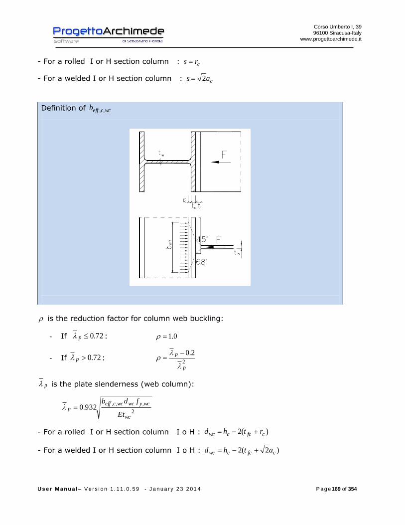
Corso Umberto I, 39 96100 Siracusa-Italy
www.progettoarchimede.it
U s e r M a n u a l – V e r s i o n 1 . 1 1 . 0 . 5 9 - J a n u a r y 2 3 2 0 1 4 P a g e 169 of 354
- For a rolled I or H section column : crs
- For a welded I or H section column : cas 2
Definition of wcceffb ,,
is the reduction factor for column web buckling:
- If 72.0p : 0.1
- If 72.0p : 2
2.0
p
p
p is the plate slenderness (web column):
2
,,,932.0
wc
wcywcwcceffp
Et
fdb
- For a rolled I or H section column I o H : )(2 cfccwc rthd
- For a welded I or H section column I o H : )2(2 cfccwc athd
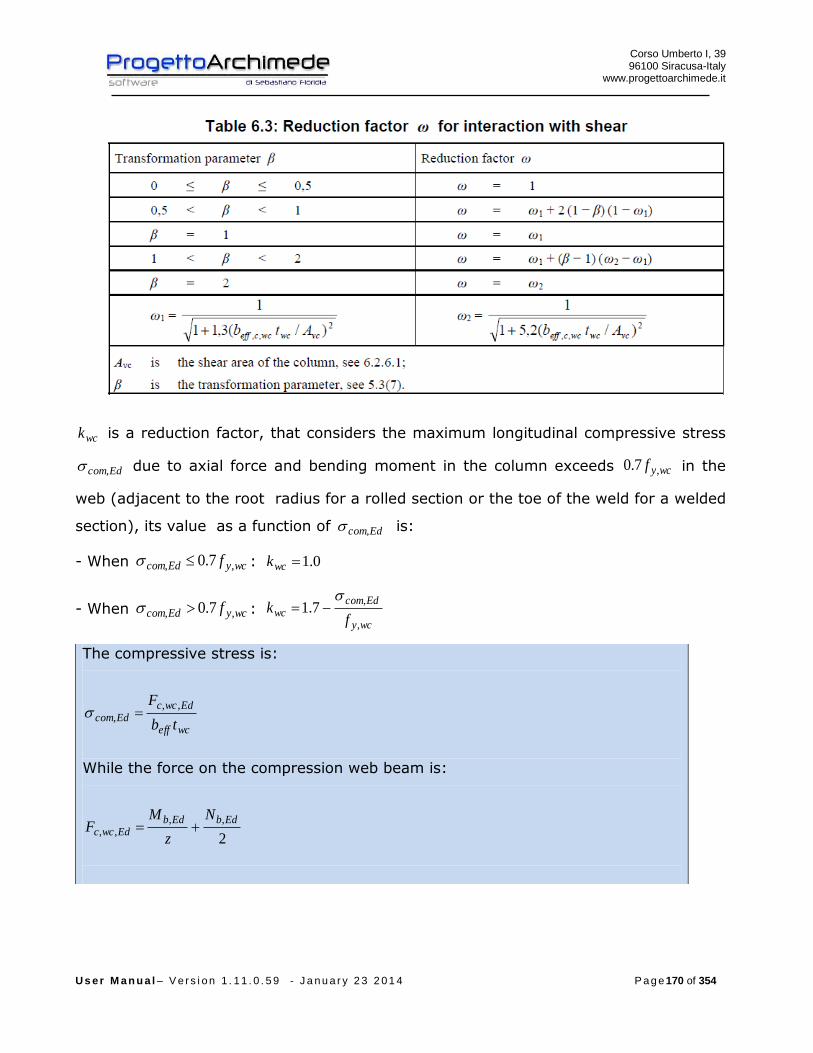
Corso Umberto I, 39 96100 Siracusa-Italy
www.progettoarchimede.it
U s e r M a n u a l – V e r s i o n 1 . 1 1 . 0 . 5 9 - J a n u a r y 2 3 2 0 1 4 P a g e 170 of 354
wck is a reduction factor, that considers the maximum longitudinal compressive stress
Edcom, due to axial force and bending moment in the column exceeds wcyf ,7.0 in the
web (adjacent to the root radius for a rolled section or the toe of the weld for a welded
section), its value as a function of Edcom, is:
- When wcyEdcom f ,, 7.0 : 0.1wck
- When wcyEdcom f ,, 7.0 : wcy
Edcomwc
fk
,
,7.1
The compressive stress is:
wceff
EdwccEdcom
tb
F ,,,
While the force on the compression web beam is:
2
,,,,
EdbEdbEdwcc
N
z
MF
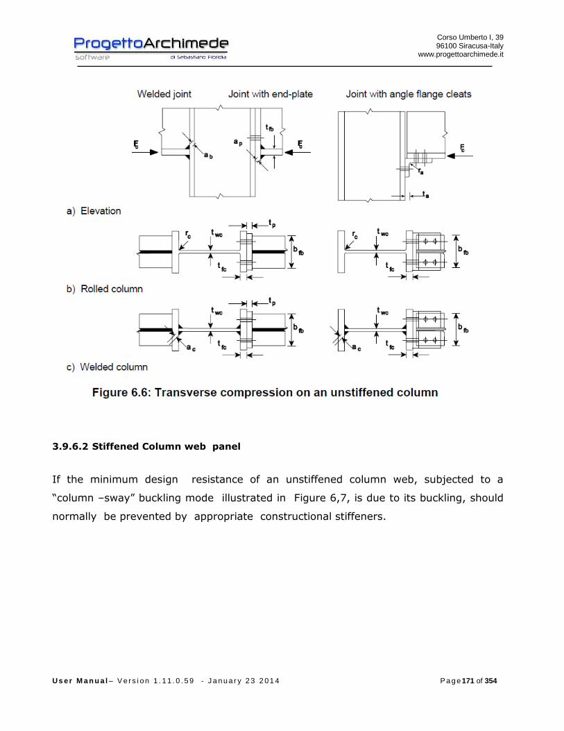
Corso Umberto I, 39 96100 Siracusa-Italy
www.progettoarchimede.it
U s e r M a n u a l – V e r s i o n 1 . 1 1 . 0 . 5 9 - J a n u a r y 2 3 2 0 1 4 P a g e 171 of 354
3.9.6.2 Stiffened Column web panel
If the minimum design resistance of an unstiffened column web, subjected to a
“column –sway” buckling mode illustrated in Figure 6,7, is due to its buckling, should
normally be prevented by appropriate constructional stiffeners.
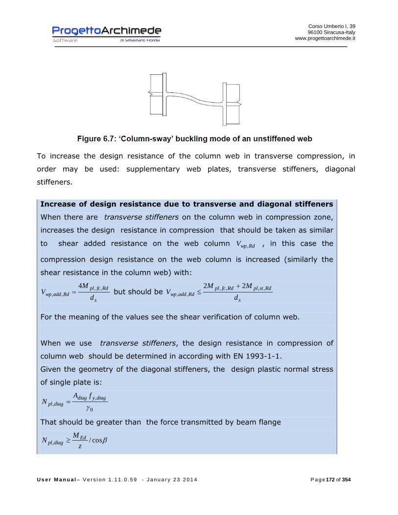
Corso Umberto I, 39 96100 Siracusa-Italy
www.progettoarchimede.it
U s e r M a n u a l – V e r s i o n 1 . 1 1 . 0 . 5 9 - J a n u a r y 2 3 2 0 1 4 P a g e 172 of 354
To increase the design resistance of the column web in transverse compression, in
order may be used: supplementary web plates, transverse stiffeners, diagonal
stiffeners.
Increase of design resistance due to transverse and diagonal stiffeners
When there are transverse stiffeners on the column web in compression zone,
increases the design resistance in compression that should be taken as similar
to shear added resistance on the web column RdwpV , , in this case the
compression design resistance on the web column is increased (similarly the
shear resistance in the column web) with:
s
Rdfcpl
Rdaddwpd
MV
,,
,,
4 but should be
s
RdstplRdfcpl
Rdaddwpd
MMV
,,,,
,,
22
For the meaning of the values see the shear verification of column web.
When we use transverse stiffeners, the design resistance in compression of
column web should be determined in according with EN 1993-1-1.
Given the geometry of the diagonal stiffeners, the design plastic normal stress
of single plate is:
0
,
,
diagydiag
diagpl
fAN
That should be greater than the force transmitted by beam flange
cos/,z
MN Ed
diagpl
Corso Umberto I, 39 96100 Siracusa-Italy
www.progettoarchimede.it
U s e r M a n u a l – V e r s i o n 1 . 1 1 . 0 . 5 9 - J a n u a r y 2 3 2 0 1 4 P a g e 173 of 354
Where
EdM is the calculation moment transmitted by a single beam
c
b
h
harctan is the angle that the diagonal forms with the axis parallel to the
beam flange
cb hh e are respectively the beam width and the length column
The design shear resistance of column web panel RdwpV , may be increased by:
cos,,, diagplRdaddwp NV
The calculation resistance with stiffeners is
RdaddwpRdwccRdwcc VFF ,,,,,,
NOTE: The joint 128 is a welded joint, the transverse stiffeners should be aligned with
the corresponding beam flange (EC3 – 1-8 point 6.2.6.2).
When the web column is reinforced by adding the supplementary web plate, should be
respected the following mechanical and geometrical sizes:
- The steel grade of the supplementary web plate should be equal to that of the
column;
- The width sb should be such that the supplementary web plate extends at least
to the toe of the root radius with of plate column or of the weld (fig. 6.5);
- The length sl should be such that the supplementary web plate extends
throughout the effective width of the web in tension and compression, see Figure
6.5;
- The thickness st of the supplementary web plate should be not less than the
column web thickness wct .

Corso Umberto I, 39 96100 Siracusa-Italy
www.progettoarchimede.it
U s e r M a n u a l – V e r s i o n 1 . 1 1 . 0 . 5 9 - J a n u a r y 2 3 2 0 1 4 P a g e 174 of 354
When there is the supplementary web plate, the effective web thickness to use for
RdwccF ,, calculation is wct5.1 , if is added a single supplementary web plate, wct0.2 if the
supplementary web plates are placed on the double-sided web. The shear web area
resistant vcA for the calculation of should be increased by wcstb
The web resistance increased are cumulative.
The local verification should be satisfied if:
RdwccEdwcc FF ,,,,
3.9.7 Resistance of web Column in transverse tension
Verification made in according with EC3 1-8 point 6.2.6.3
Column web in tension and references
3.9.7.1 Unstiffened column web panel
The design resistance of an unstiffened column web subject to transverse tension
should be determined from:
Corso Umberto I, 39 96100 Siracusa-Italy
www.progettoarchimede.it
U s e r M a n u a l – V e r s i o n 1 . 1 1 . 0 . 5 9 - J a n u a r y 2 3 2 0 1 4 P a g e 175 of 354
0
,,,
,,M
wcywcwcteff
Rdwct
ftbF
where:
is a reduction factor to allow the possible effects of interaction with shear in the
column web panel according to table 6.3.
wcteffb ,, is the effective width of column web in tension that for end-plate connection is:
)(522,, statb fcbfbwcteff (6.16)
where:
- For a rolled I or H section column : crs
- For a welded I or H section column : cas 2
where:
ca e cr are as indicated Figure 6.8 e ba is as indicated Figure 6.6.

Corso Umberto I, 39 96100 Siracusa-Italy
www.progettoarchimede.it
U s e r M a n u a l – V e r s i o n 1 . 1 1 . 0 . 5 9 - J a n u a r y 2 3 2 0 1 4 P a g e 176 of 354
The reduction factor to allow for the possible effects of interaction with shear in the
column web panel should be determined from table 6.3, using the value of wcteffb ,,
determined for the connection considered.
3.9.7.2 Stiffened column web panel
To increase the design resistance of the column web in transverse tension, in order
may be used: supplementary web plates, transverse stiffeners, diagonal stiffeners.
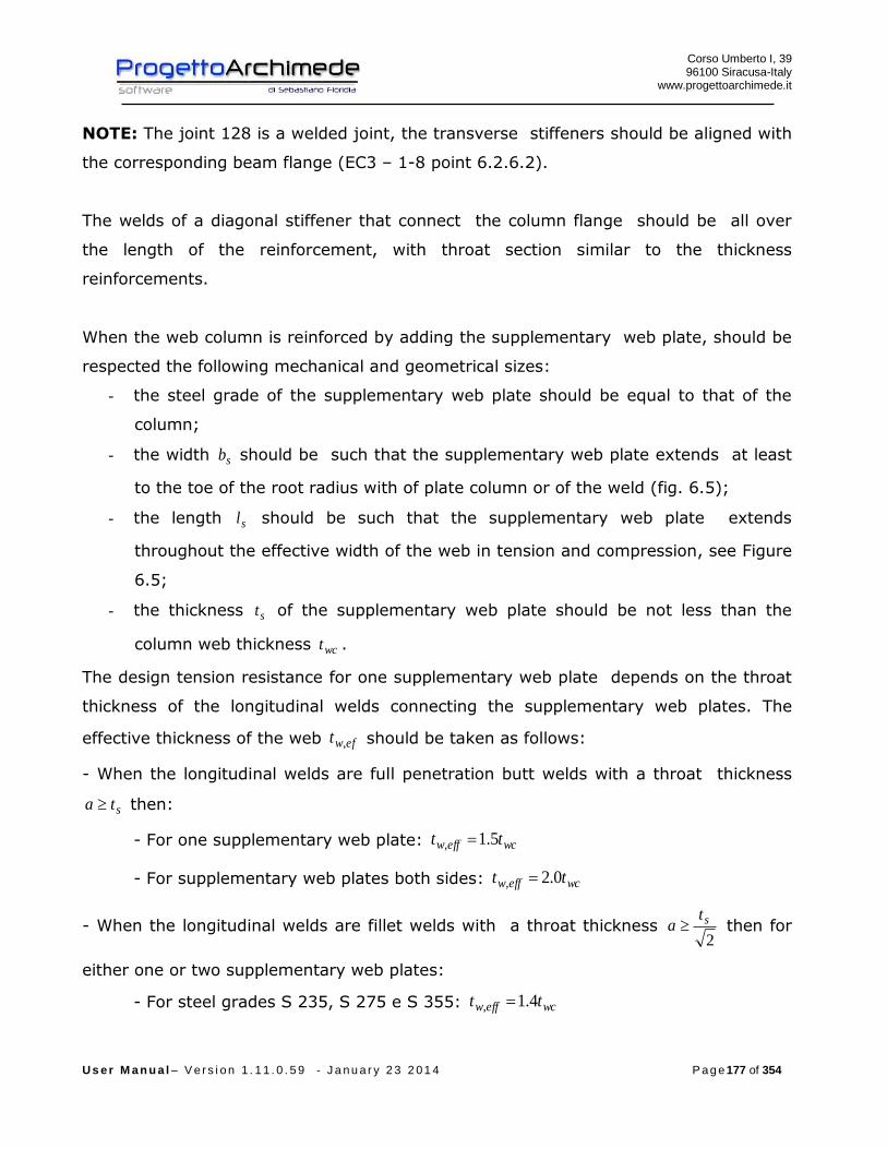
Corso Umberto I, 39 96100 Siracusa-Italy
www.progettoarchimede.it
U s e r M a n u a l – V e r s i o n 1 . 1 1 . 0 . 5 9 - J a n u a r y 2 3 2 0 1 4 P a g e 177 of 354
NOTE: The joint 128 is a welded joint, the transverse stiffeners should be aligned with
the corresponding beam flange (EC3 – 1-8 point 6.2.6.2).
The welds of a diagonal stiffener that connect the column flange should be all over
the length of the reinforcement, with throat section similar to the thickness
reinforcements.
When the web column is reinforced by adding the supplementary web plate, should be
respected the following mechanical and geometrical sizes:
- the steel grade of the supplementary web plate should be equal to that of the
column;
- the width sb should be such that the supplementary web plate extends at least
to the toe of the root radius with of plate column or of the weld (fig. 6.5);
- the length sl should be such that the supplementary web plate extends
throughout the effective width of the web in tension and compression, see Figure
6.5;
- the thickness st of the supplementary web plate should be not less than the
column web thickness wct .
The design tension resistance for one supplementary web plate depends on the throat
thickness of the longitudinal welds connecting the supplementary web plates. The
effective thickness of the web efwt , should be taken as follows:
- When the longitudinal welds are full penetration butt welds with a throat thickness
sta then:
- For one supplementary web plate: wceffw tt 5.1,
- For supplementary web plates both sides: wceffw tt 0.2,
- When the longitudinal welds are fillet welds with a throat thickness 2
sta then for
either one or two supplementary web plates:
- For steel grades S 235, S 275 e S 355: wceffw tt 4.1,
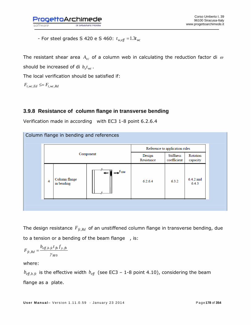
Corso Umberto I, 39 96100 Siracusa-Italy
www.progettoarchimede.it
U s e r M a n u a l – V e r s i o n 1 . 1 1 . 0 . 5 9 - J a n u a r y 2 3 2 0 1 4 P a g e 178 of 354
- For steel grades S 420 e S 460: wceffw tt 3.1,
The resistant shear area vcA of a column web in calculating the reduction factor di
should be increased of di wcstb .
The local verification should be satisfied if:
RdwctEdwct FF ,,,,
3.9.8 Resistance of column flange in transverse bending
Verification made in according with EC3 1-8 point 6.2.6.4
Column flange in bending and references
The design resistance RdfcF , of an unstiffened column flange in transverse bending, due
to a tension or a bending of the beam flange , is:
0
,.,
,M
fbyfbfcbeff
Rdfc
ftbF
where:
fcbeffb ,, is the effective width effb (see EC3 – 1-8 point 4.10), considering the beam
flange as a plate.

Corso Umberto I, 39 96100 Siracusa-Italy
www.progettoarchimede.it
U s e r M a n u a l – V e r s i o n 1 . 1 1 . 0 . 5 9 - J a n u a r y 2 3 2 0 1 4 P a g e 179 of 354
The effective width effb is
fweff ktstb 72
where:
)/)(/( ,, pyfypf ffttk but should be 1k
fyf , is the yield strength of the flange of the I or H section;
pyf , is the yield strength of the plate welded to the I or H section.
The dimension s should be obtained from:
- For a rolled I or H section : rs
- For a welded I or H section : as 2
For an unstiffened flange of an I or H section, the following criterion should be
satisfied:
puypyeff bffb )/( ,,
where:
pyf , the ultimate strength of the plate welded to the I or H section;
pb is the width of the plate welded to the I or H section.
Otherwise the joint should be stiffened.
3.9.9 Plate and web beam in compression
Verification made in according with EC3 1-8 point 6.2.6.7
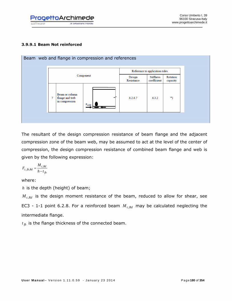
Corso Umberto I, 39 96100 Siracusa-Italy
www.progettoarchimede.it
U s e r M a n u a l – V e r s i o n 1 . 1 1 . 0 . 5 9 - J a n u a r y 2 3 2 0 1 4 P a g e 180 of 354
3.9.9.1 Beam Not reinforced
Beam web and flange in compression and references
The resultant of the design compression resistance of beam flange and the adjacent
compression zone of the beam web, may be assumed to act at the level of the center of
compression, the design compression resistance of combined beam flange and web is
given by the following expression:
fb
RdcRdfbc
th
MF
,,,
where:
h is the depth (height) of beam;
RdcM , is the design moment resistance of the beam, reduced to allow for shear, see
EC3 - 1-1 point 6.2.8. For a reinforced beam RdcM , may be calculated neglecting the
intermediate flange.
fbt is the flange thickness of the connected beam.
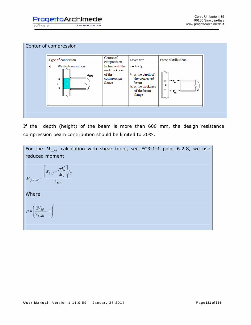
Corso Umberto I, 39 96100 Siracusa-Italy
www.progettoarchimede.it
U s e r M a n u a l – V e r s i o n 1 . 1 1 . 0 . 5 9 - J a n u a r y 2 3 2 0 1 4 P a g e 181 of 354
Center of compression
If the depth (height) of the beam is more than 600 mm, the design resistance
compression beam contribution should be limited to 20%.
For the RdcM , calculation with shear force, see EC3-1-1 point 6.2.8, we use
reduced moment
0
2
,
,,
4
M
yw
wypl
RdVy
ft
AW
M
Where
2
,
12
Rdpl
Ed
V
V
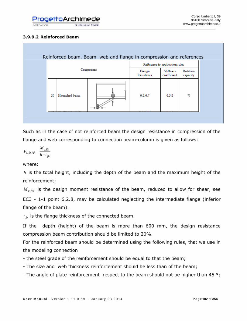
Corso Umberto I, 39 96100 Siracusa-Italy
www.progettoarchimede.it
U s e r M a n u a l – V e r s i o n 1 . 1 1 . 0 . 5 9 - J a n u a r y 2 3 2 0 1 4 P a g e 182 of 354
3.9.9.2 Reinforced Beam
Reinforced beam. Beam web and flange in compression and references
Such as in the case of not reinforced beam the design resistance in compression of the
flange and web corresponding to connection beam-column is given as follows:
fb
RdcRdfbc
th
MF
,,,
where:
h is the total height, including the depth of the beam and the maximum height of the
reinforcement;
RdcM , is the design moment resistance of the beam, reduced to allow for shear, see
EC3 - 1-1 point 6.2.8, may be calculated neglecting the intermediate flange (inferior
flange of the beam).
fbt is the flange thickness of the connected beam.
If the depth (height) of the beam is more than 600 mm, the design resistance
compression beam contribution should be limited to 20%.
For the reinforced beam should be determined using the following rules, that we use in
the modeling connection
- the steel grade of the reinforcement should be equal to that the beam;
- The size and web thickness reinforcement should be less than of the beam;
- The angle of plate reinforcement respect to the beam should not be higher than 45 °;

Corso Umberto I, 39 96100 Siracusa-Italy
www.progettoarchimede.it
U s e r M a n u a l – V e r s i o n 1 . 1 1 . 0 . 5 9 - J a n u a r y 2 3 2 0 1 4 P a g e 183 of 354
For a reinforced beam, the web beam is subject to compression force, its design
resistance is calculated in according EC3 1-8 point 6.2.6.2 (see resistance of column
web in transverse compression).
3.9.10 Weldings
Design resistance of fillet weld is:
lafF dvwRdw .,
Where
dvwf . is weld shear design resistance.
a is height throat weld.
l is length cordon weld.
The welding shear calculation resistance dvwf . is:
2.
3/
Mw
udvw
ff
where:
uf is nominal breaking resistance of the weakest node;
w is the appropriate correlation factor shown in Table 4.1.
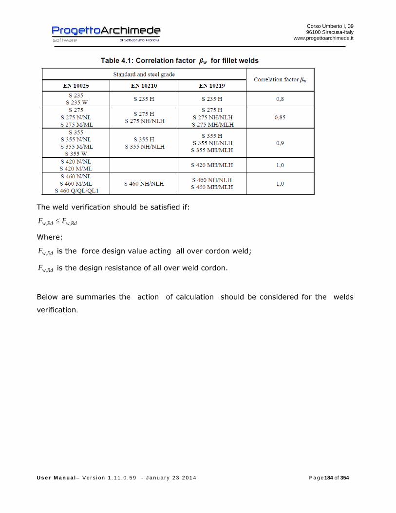
Corso Umberto I, 39 96100 Siracusa-Italy
www.progettoarchimede.it
U s e r M a n u a l – V e r s i o n 1 . 1 1 . 0 . 5 9 - J a n u a r y 2 3 2 0 1 4 P a g e 184 of 354
The weld verification should be satisfied if:
RdwEdw FF ,,
Where:
EdwF , is the force design value acting all over cordon weld;
RdwF , is the design resistance of all over weld cordon.
Below are summaries the action of calculation should be considered for the welds
verification.
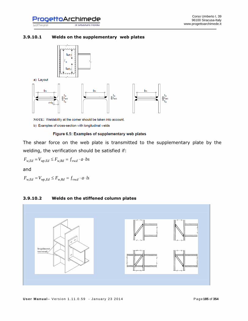
Corso Umberto I, 39 96100 Siracusa-Italy
www.progettoarchimede.it
U s e r M a n u a l – V e r s i o n 1 . 1 1 . 0 . 5 9 - J a n u a r y 2 3 2 0 1 4 P a g e 185 of 354
3.9.10.1 Welds on the supplementary web plates
The shear force on the web plate is transmitted to the supplementary plate by the
welding, the verification should be satisfied if:
bsafFVF dvwRdwEdwpEdw .,.,
and
lsafFVF dvwRdwEdwpEdw .,,,
3.9.10.2 Welds on the stiffened column plates
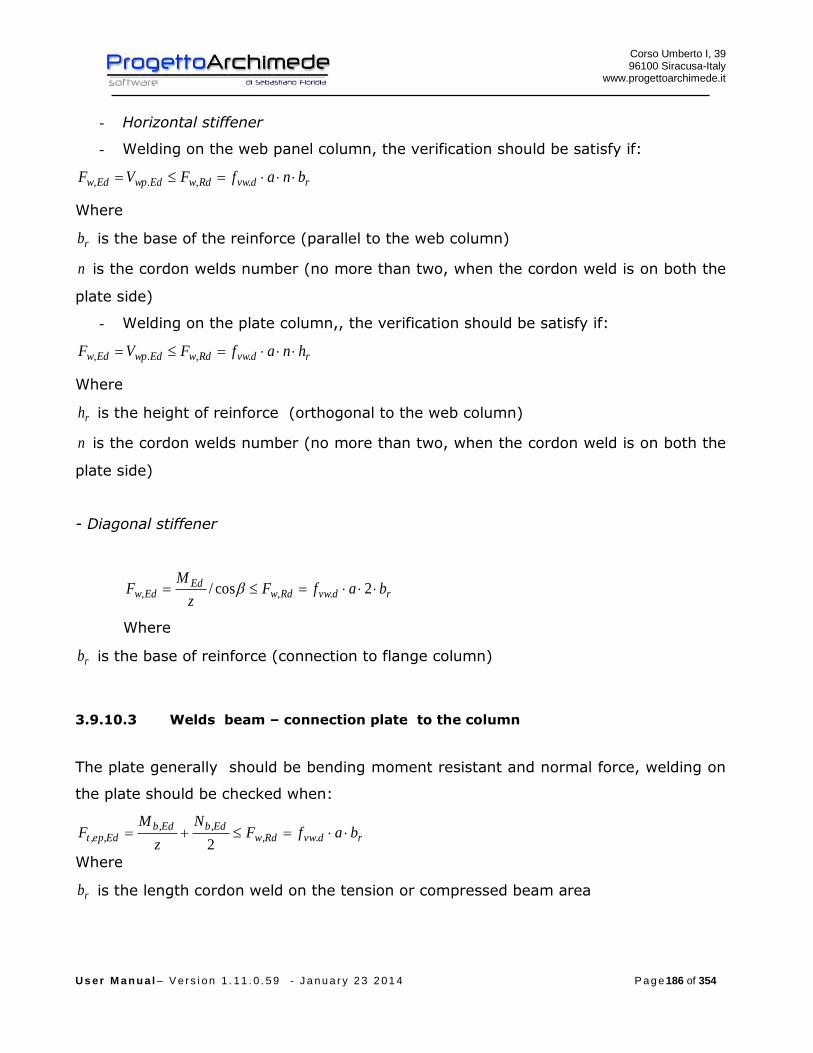
Corso Umberto I, 39 96100 Siracusa-Italy
www.progettoarchimede.it
U s e r M a n u a l – V e r s i o n 1 . 1 1 . 0 . 5 9 - J a n u a r y 2 3 2 0 1 4 P a g e 186 of 354
- Horizontal stiffener
- Welding on the web panel column, the verification should be satisfy if:
rdvwRdwEdwpEdw bnafFVF .,.,
Where
rb is the base of the reinforce (parallel to the web column)
n is the cordon welds number (no more than two, when the cordon weld is on both the
plate side)
- Welding on the plate column,, the verification should be satisfy if:
rdvwRdwEdwpEdw hnafFVF .,.,
Where
rh is the height of reinforce (orthogonal to the web column)
n is the cordon welds number (no more than two, when the cordon weld is on both the
plate side)
- Diagonal stiffener
rdvwRdwEd
Edw bafFz
MF 2cos/ .,,
Where
rb is the base of reinforce (connection to flange column)
3.9.10.3 Welds beam – connection plate to the column
The plate generally should be bending moment resistant and normal force, welding on
the plate should be checked when:
rdvwRdwEdbEdb
Edept bafFN
z
MF .,
,,,,
2 Where
rb is the length cordon weld on the tension or compressed beam area

Corso Umberto I, 39 96100 Siracusa-Italy
www.progettoarchimede.it
U s e r M a n u a l – V e r s i o n 1 . 1 1 . 0 . 5 9 - J a n u a r y 2 3 2 0 1 4 P a g e 187 of 354
The web beam generally should be shear resisting, the welding on the web should be
checked when:
rdvwRdwEdept hafFVF .,,,
Where
rh is length cordon weld on the web column
3.9.11 Joint design resistance due to axial force
The design resistance for only normal stress RdjN , is calculated as the less value of
single design resistance calculated for the joint ( first considered) , if is compression
force or tension force.
3.9.11.1 Compression design resistance
The compression design resistance RdjN , is the smallest of following values:
- Column Web panel in transverse compression RdwccF ,,2
- Plate and beam web in compression bplN , ( plastic normal stress of the beam).
3.9.11.2 Tension design resistance
The normal stress tension RdjN , of connection beam-column of a welded joint is the
smallest of following values:
- Web Beam welded with column plate RdwF ,
- Column Web in transverse tension RdwctF ,,
- Web beam in tension RdwbtF ,,,
- Flange and web beam in tension bplN ,
3.9.12 Shear resistance
The shear force is totally transferred to the weld.
Corso Umberto I, 39 96100 Siracusa-Italy
www.progettoarchimede.it
U s e r M a n u a l – V e r s i o n 1 . 1 1 . 0 . 5 9 - J a n u a r y 2 3 2 0 1 4 P a g e 188 of 354
The shear resistance RdjV , of connection beam-column of a welded joint with plate
should be determined by:
rdvwRdwRdj hafFV .,,
Where
rh is length cordon weld on the web column
3.9.13 Resistance to bending force
The design moment resistance in bending of a welded joint should be calculated as
shown in Figure 6.15 (a).
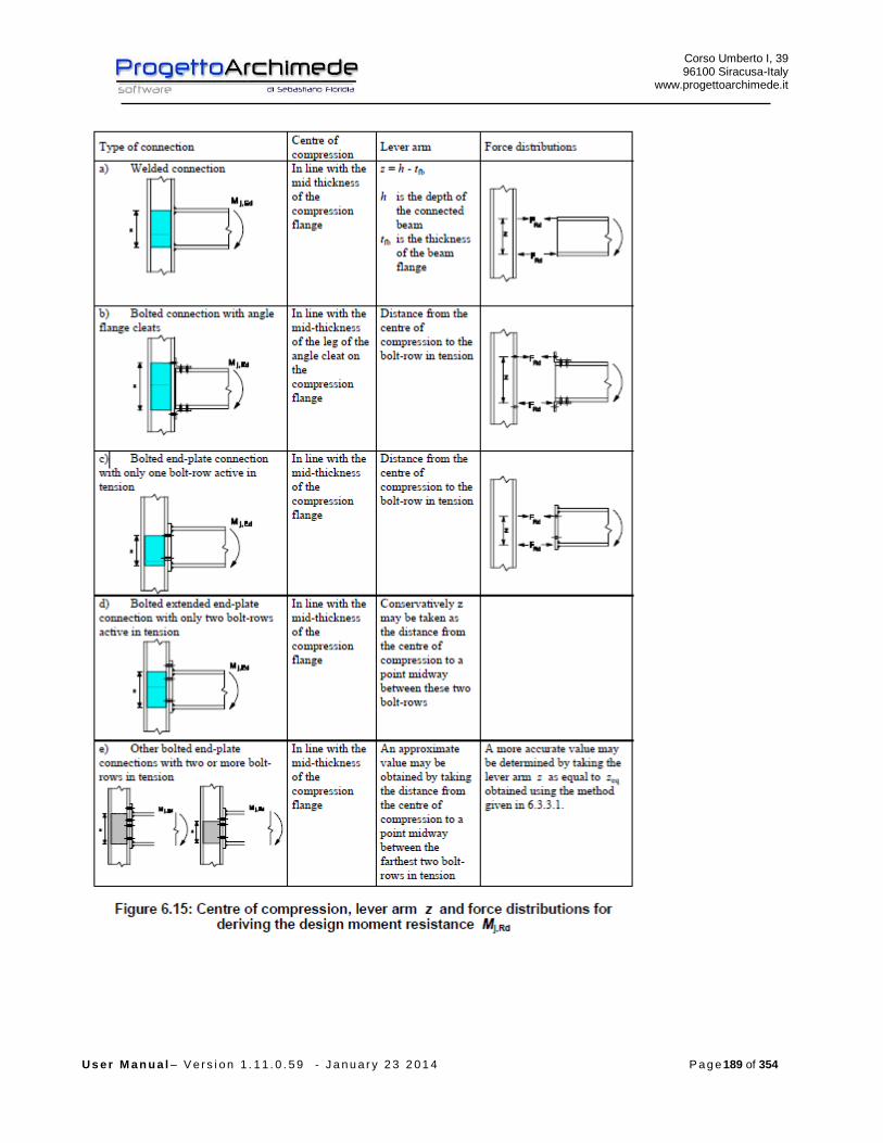
Corso Umberto I, 39 96100 Siracusa-Italy
www.progettoarchimede.it
U s e r M a n u a l – V e r s i o n 1 . 1 1 . 0 . 5 9 - J a n u a r y 2 3 2 0 1 4 P a g e 189 of 354

Corso Umberto I, 39 96100 Siracusa-Italy
www.progettoarchimede.it
U s e r M a n u a l – V e r s i o n 1 . 1 1 . 0 . 5 9 - J a n u a r y 2 3 2 0 1 4 P a g e 190 of 354
The moment of calculation should be taken as not less than a moment equal to 25% of
plastic moment of the weaker section, if the action is less.
The design moment resistance RdjM , of welded joint beam- to-column may be
determined from:
zFM RdtrRdj ,,
where:
RdtrF , is the effective design resistance of tension calculation of the member;
rz is the distance from the compression center;
The center of compression should be assumed to be in line with the center of the
compression flange of the connected member.
The effective design tension resistance RdtrF , should be taken as the smallest value of
the design tension resistance for a single basic component:
- Web Beam welded with column plate RdwF ,
- The column web in transverse tension RdwctF ,,
- The column flange in transverse bending RdfctF ,,,
- The beam web in tension RdwbtF ,,,
The effective design tension resistance RdtrF , , should be reduced below the value of
RdtrF , to ensure that:
- The total design resistance
RdwpRdtr
VF
,, ;
- The total design resistance RdtrF , does not exceed the following smaller values:
- The design resistance of the column web in compression RdwccF ,,, ;

Corso Umberto I, 39 96100 Siracusa-Italy
www.progettoarchimede.it
U s e r M a n u a l – V e r s i o n 1 . 1 1 . 0 . 5 9 - J a n u a r y 2 3 2 0 1 4 P a g e 191 of 354
- The design resistance of the plate and beam web in compression RdfbcF ,,, .
3.9.14 Resistance to buckling and tension-bending
If the axial force EdN on the beam exceed the 5% of the design resistance RdplN , , the
conservative domain should be used is :
1,
,
,
,
Rdj
Edj
Rdj
Edj
N
N
M
M

Corso Umberto I, 39 96100 Siracusa-Italy
www.progettoarchimede.it
U s e r M a n u a l – V e r s i o n 1 . 1 1 . 0 . 5 9 - J a n u a r y 2 3 2 0 1 4 P a g e 192 of 354
3.10 Joint 40 (Beam – plate column bolted, reinforced)
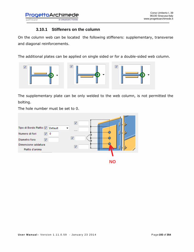
Corso Umberto I, 39 96100 Siracusa-Italy
www.progettoarchimede.it
U s e r M a n u a l – V e r s i o n 1 . 1 1 . 0 . 5 9 - J a n u a r y 2 3 2 0 1 4 P a g e 193 of 354
3.10.1 Stiffeners on the column
On the column web can be located the following stiffeners: supplementary, transverse
and diagonal reinforcements.
The additional plates can be applied on single sided or for a double-sided web column.
The supplementary plate can be only welded to the web column, is not permitted the
bolting.
The hole number must be set to 0.

Corso Umberto I, 39 96100 Siracusa-Italy
www.progettoarchimede.it
U s e r M a n u a l – V e r s i o n 1 . 1 1 . 0 . 5 9 - J a n u a r y 2 3 2 0 1 4 P a g e 194 of 354
The transverse reinforcements can be placed corresponding : superior web beam plate,
inferior web beam plate or end base reinforcement.
The stiffener cross geometry considers the reinforcement on the beam.
3.10.2 Stiffeners on the beam
Corso Umberto I, 39 96100 Siracusa-Italy
www.progettoarchimede.it
U s e r M a n u a l – V e r s i o n 1 . 1 1 . 0 . 5 9 - J a n u a r y 2 3 2 0 1 4 P a g e 195 of 354
3.10.3 Forces
On the profiles can be applied the following forces:
EdN normal force (positive if tension force)
xEdV , horizontal shear
yEdV , vertical shear
xEdM , bending moment all round x axis
The forces can be inserted by Tekla Structures (except xEdV , ), by modeler Midas, by
text file or we can calculate the structure to restore resistance.
If the stresses from Tekla Structures are zero, the actions will have minimum value in
according with EC3 1-8 point 6.2.7.1 (13)
plEd NN 025.0
plyEd VV 025.0,
where the plastic resistances are referred to the column.
3.10.4 Geometric verification
The procedure provides to verify the construction requirements for drilling bolted
joint, in according with l’EC3 1-8 and the following table 3.3 and figure 3.1.
The verification is made only for e1 and e2, and not for p1 e p2 because the local
buckling resistance of the plate is always prevented by the stiffeners (fasteners) and
by the same column.

Corso Umberto I, 39 96100 Siracusa-Italy
www.progettoarchimede.it
U s e r M a n u a l – V e r s i o n 1 . 1 1 . 0 . 5 9 - J a n u a r y 2 3 2 0 1 4 P a g e 196 of 354

Corso Umberto I, 39 96100 Siracusa-Italy
www.progettoarchimede.it
U s e r M a n u a l – V e r s i o n 1 . 1 1 . 0 . 5 9 - J a n u a r y 2 3 2 0 1 4 P a g e 197 of 354
3.10.5 Design resistance of single bolt and single weld
In this paragraph we recall the common criteria for verification of single bolts and
single weld.
Corso Umberto I, 39 96100 Siracusa-Italy
www.progettoarchimede.it
U s e r M a n u a l – V e r s i o n 1 . 1 1 . 0 . 5 9 - J a n u a r y 2 3 2 0 1 4 P a g e 198 of 354
3.10.5.1 Design resistance at Bolt tensile force
Tensile strength of single bolt is:
2,
9.0
M
subRdt
AfF
Where
sA is stressed tensile area
ubf is the last tensile of bolt
3.10.5.2 Bolt shear design resistance
For a shear connection (see class A EC3 1-8 point3.4.1) the single bolt shear strength
design (for a single resistant section) is :
2
,,M
ubvRdv
AfF
If the shear plane is through the threaded bolt portion:
- for classes 4.6, 5.6 e 8.8
6.0v
- for classes 4.8, 5.8 e 10.9
5.0v
If the shear plane is through not threaded bolt portion:
6.0v
while
A is the bolt area
ubf is the last bolt tensile stress
3.10.5.3 Design resistance of the weld
Design resistance of fillet weld is:
lafF dvwRdw .,
Where
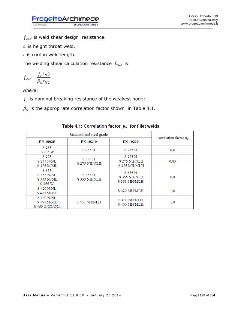
Corso Umberto I, 39 96100 Siracusa-Italy
www.progettoarchimede.it
U s e r M a n u a l – V e r s i o n 1 . 1 1 . 0 . 5 9 - J a n u a r y 2 3 2 0 1 4 P a g e 199 of 354
dvwf . is weld shear design resistance.
a is height throat weld.
l is cordon weld length.
The welding shear calculation resistance dvwf . is:
2.
3/
Mw
udvw
ff
where:
uf is nominal breaking resistance of the weakest node;
w is the appropriate correlation factor shown in Table 4.1.
Corso Umberto I, 39 96100 Siracusa-Italy
www.progettoarchimede.it
U s e r M a n u a l – V e r s i o n 1 . 1 1 . 0 . 5 9 - J a n u a r y 2 3 2 0 1 4 P a g e 200 of 354
3.10.6 Verifications made
The verifications made on the joint are the following:
- Verification column web panel in shear
RdwpEdwp VV ,,
- Verification column web in compression
RdwccEdwcc FF ,,,,
- Plate and beam web in compression
RdfbcEdfbc FF ,,,,
- Bearing resistance verification on two horizontal directions on the connection
plate
RdbEdb FF ,,
- Verification beam web panel in shear
RdwpEdwp VV ,,
- Verification beam web in compression
RdwccEdwcc FF ,,,,
- Axial force resistance without moment resistance applied
- Verification axial force resistance without moment resistance applied
1,
,
Rdj
Edj
N
N
- Verification for shear force
1,
,
Rdj
Edj
V
V
- Bending force resistance without axial force
1,
,
Rdj
Edj
M
M

Corso Umberto I, 39 96100 Siracusa-Italy
www.progettoarchimede.it
U s e r M a n u a l – V e r s i o n 1 . 1 1 . 0 . 5 9 - J a n u a r y 2 3 2 0 1 4 P a g e 201 of 354
- Verification in buckling
1,
,
,
,
Rdj
Edj
Rdj
Edj
N
N
M
M
If the axial force EdN does not exceed the 5% of the plastic axial force RdplN , , is
neglected the coexistence of the axial force and the rule becomes
1,
,
Rdj
Edj
M
M
3.10.7 Design resistance of column web panel in shear
Verification made according with EC3 1-8 point 6.2.6.1
Shear action in the column web and references
The design resistance calculation of column web in shear, is valid provided the column
web slenderness satisfies the condition
69/ wtd
Where
rthd f 2)2( height web
yf
235 coefficient that considers the material

Corso Umberto I, 39 96100 Siracusa-Italy
www.progettoarchimede.it
U s e r M a n u a l – V e r s i o n 1 . 1 1 . 0 . 5 9 - J a n u a r y 2 3 2 0 1 4 P a g e 202 of 354
3.10.7.1 Unstiffened web panel column
For a single –sided joint, in or for a double-sided joint which the depths are similar the
design plastic shear resistance RdwpV , of an unstiffened column web panel , subject to a
design shear force EdwpV , , should be obtained using:
0
,
,3
09
M
vcwcy
Rdwp
AfV
Where:
fwfv trtbtAA )2(2 is the shear area of the column, see EN 1993-1-1.
22 8584.0)2(2)4()2(2 rtthbtrtthbtA wffwff
is the cross section area.
Single-sided-joint
and
double-sided-joint

Corso Umberto I, 39 96100 Siracusa-Italy
www.progettoarchimede.it
U s e r M a n u a l – V e r s i o n 1 . 1 1 . 0 . 5 9 - J a n u a r y 2 3 2 0 1 4 P a g e 203 of 354
Design shear force EdwpV , is given by:
2
,2,1,2,1,
EdcEdcEdbEdbEdwp
VV
z
MMV
In JFT the value according to the above expression, is calculated only if the data
derived from a software calculation that allows the determination of the forces all over
the joint (see Midas or from text file).
If the stresses are recorded by Tekla the shear force considered is:
z
MV Ed
Edwp ,
Where:
z is the lever arm that is bfb thz ,

Corso Umberto I, 39 96100 Siracusa-Italy
www.progettoarchimede.it
U s e r M a n u a l – V e r s i o n 1 . 1 1 . 0 . 5 9 - J a n u a r y 2 3 2 0 1 4 P a g e 204 of 354
The forces that contribute to the shear calculation EdwpV , are shown in the following
figure,
3.10.7.2 Stiffened column web panel
The design shear resistance on the column web may be increased by the use of
horizontal or transverse stiffeners or supplementary web plates.
Where transverse web stiffeners are used in both the compression zone and the tension
zone, the design plastic shear resistance of the column web panel RdwpV , may be
increased , by:
s
Rdfcpl
Rdaddwpd
MV
,,
,,
4 but should be
s
RdstplRdfcpl
Rdaddwpd
MMV
,,,,
,,
22
That should be taken the smaller between the two
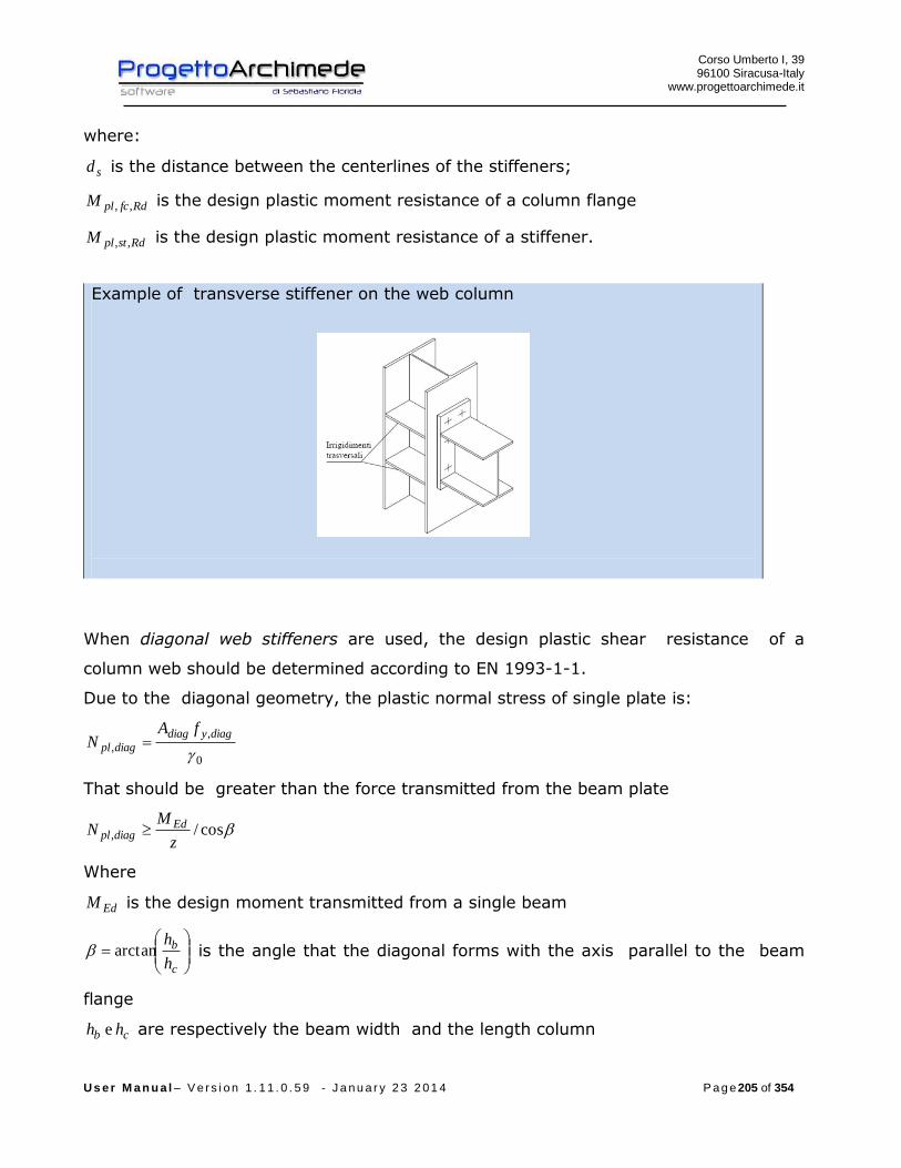
Corso Umberto I, 39 96100 Siracusa-Italy
www.progettoarchimede.it
U s e r M a n u a l – V e r s i o n 1 . 1 1 . 0 . 5 9 - J a n u a r y 2 3 2 0 1 4 P a g e 205 of 354
where:
sd is the distance between the centerlines of the stiffeners;
RdfcplM ,, is the design plastic moment resistance of a column flange
RdstplM ,, is the design plastic moment resistance of a stiffener.
Example of transverse stiffener on the web column
When diagonal web stiffeners are used, the design plastic shear resistance of a
column web should be determined according to EN 1993-1-1.
Due to the diagonal geometry, the plastic normal stress of single plate is:
0
,
,
diagydiag
diagpl
fAN
That should be greater than the force transmitted from the beam plate
cos/,z
MN Ed
diagpl
Where
EdM is the design moment transmitted from a single beam
c
b
h
harctan is the angle that the diagonal forms with the axis parallel to the beam
flange
cb hh e are respectively the beam width and the length column

Corso Umberto I, 39 96100 Siracusa-Italy
www.progettoarchimede.it
U s e r M a n u a l – V e r s i o n 1 . 1 1 . 0 . 5 9 - J a n u a r y 2 3 2 0 1 4 P a g e 206 of 354
The design shear resistance of column web panel RdwpV , may be increased by:
cos,,, diagplRdaddwp NV
Example of diagonal stiffener on the web column
If the column web is reinforced by adding a supplementary web plate, see figure 6.5,
the shear area vcwA may be increased by wcstb . If a further supplementary web plate is
added on the other side of the web column, no further increase of the shear area
should be made.
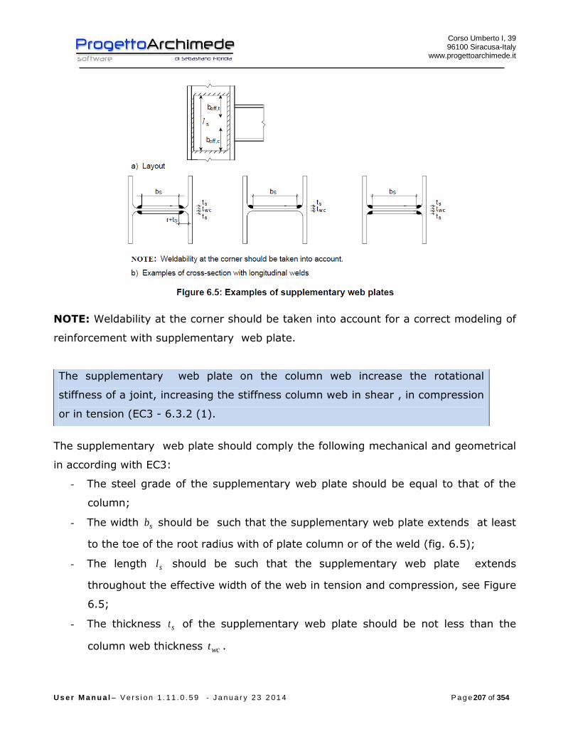
Corso Umberto I, 39 96100 Siracusa-Italy
www.progettoarchimede.it
U s e r M a n u a l – V e r s i o n 1 . 1 1 . 0 . 5 9 - J a n u a r y 2 3 2 0 1 4 P a g e 207 of 354
NOTE: Weldability at the corner should be taken into account for a correct modeling of
reinforcement with supplementary web plate.
The supplementary web plate on the column web increase the rotational
stiffness of a joint, increasing the stiffness column web in shear , in compression
or in tension (EC3 - 6.3.2 (1).
The supplementary web plate should comply the following mechanical and geometrical
in according with EC3:
- The steel grade of the supplementary web plate should be equal to that of the
column;
- The width sb should be such that the supplementary web plate extends at least
to the toe of the root radius with of plate column or of the weld (fig. 6.5);
- The length sl should be such that the supplementary web plate extends
throughout the effective width of the web in tension and compression, see Figure
6.5;
- The thickness st of the supplementary web plate should be not less than the
column web thickness wct .
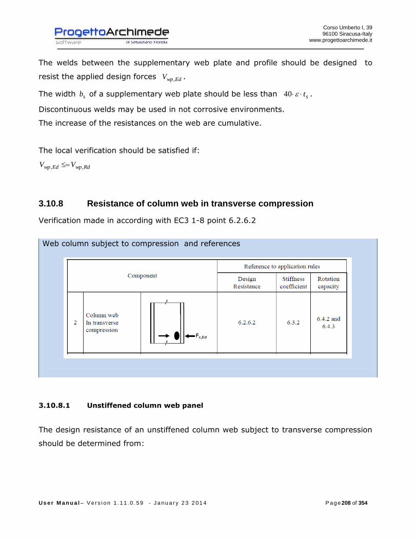
Corso Umberto I, 39 96100 Siracusa-Italy
www.progettoarchimede.it
U s e r M a n u a l – V e r s i o n 1 . 1 1 . 0 . 5 9 - J a n u a r y 2 3 2 0 1 4 P a g e 208 of 354
The welds between the supplementary web plate and profile should be designed to
resist the applied design forces EdwpV , .
The width sb of a supplementary web plate should be less than st40 .
Discontinuous welds may be used in not corrosive environments.
The increase of the resistances on the web are cumulative.
The local verification should be satisfied if:
RdwpEdwp VV ,,
3.10.8 Resistance of column web in transverse compression
Verification made in according with EC3 1-8 point 6.2.6.2
Web column subject to compression and references
3.10.8.1 Unstiffened column web panel
The design resistance of an unstiffened column web subject to transverse compression
should be determined from:

Corso Umberto I, 39 96100 Siracusa-Italy
www.progettoarchimede.it
U s e r M a n u a l – V e r s i o n 1 . 1 1 . 0 . 5 9 - J a n u a r y 2 3 2 0 1 4 P a g e 209 of 354
0
,.,,,
M
wcywcwcceffwcRdwcc
ftbkF
but
1
,.,,,
M
wcywcwcceffwcRdwcc
ftbkF
We consider as resistance of column web subject to transverse compression the less
of two values.
The first expression represents the web resistance for crushing (in the figure is
represented with the letter “l”, column web crushing), the second expression
represents the resistance for column web buckling (in the figure is represented
with the letter “m”, column web buckling).
Where:
is a reduction factor to allow the possible effects of interaction with shear in the
column web panel according to Table 6.3;
wcceffb ,, is the effective width of column web in compression that for bolted end-plate
connection is:
pfcpfbwcceff sstatb )(522,,
where :
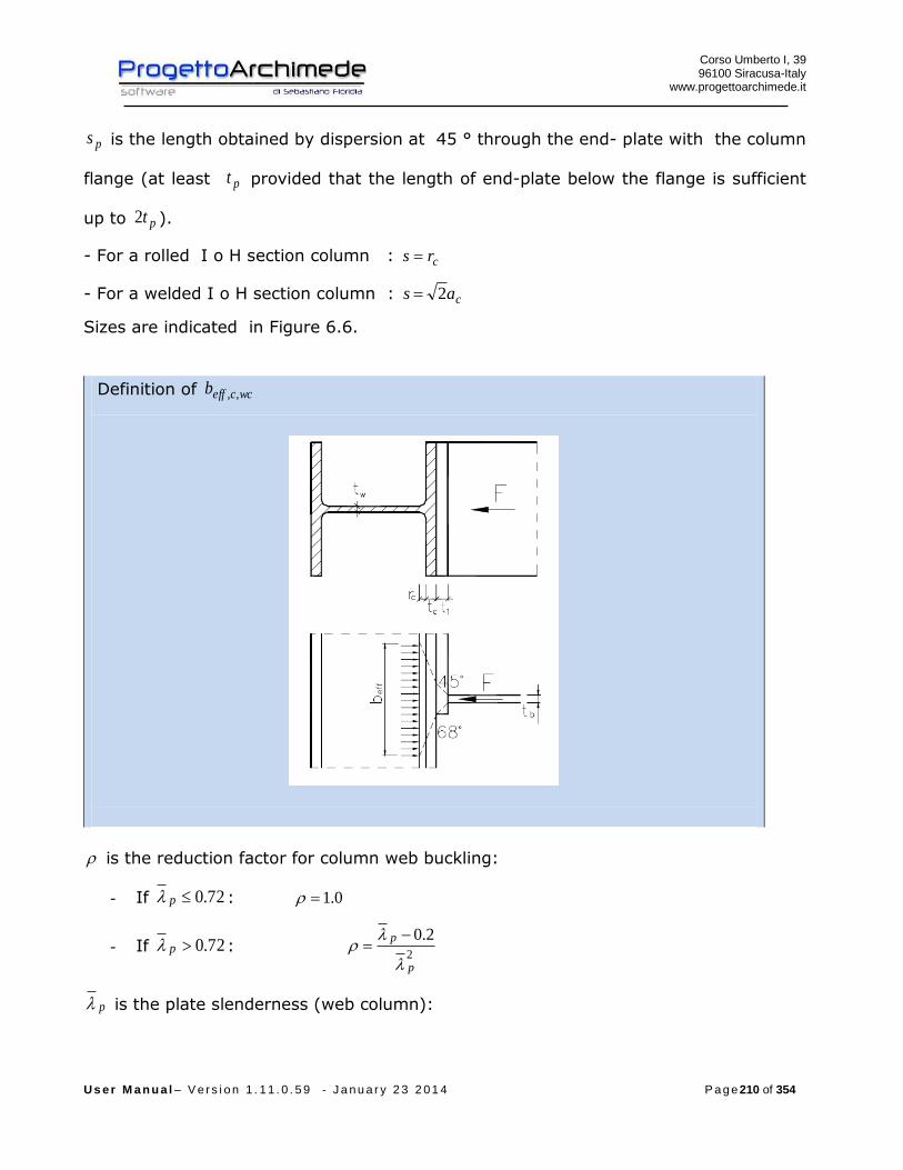
Corso Umberto I, 39 96100 Siracusa-Italy
www.progettoarchimede.it
U s e r M a n u a l – V e r s i o n 1 . 1 1 . 0 . 5 9 - J a n u a r y 2 3 2 0 1 4 P a g e 210 of 354
ps is the length obtained by dispersion at 45 ° through the end- plate with the column
flange (at least pt provided that the length of end-plate below the flange is sufficient
up to pt2 ).
- For a rolled I o H section column : crs
- For a welded I o H section column : cas 2
Sizes are indicated in Figure 6.6.
Definition of wcceffb ,,
is the reduction factor for column web buckling:
- If 72.0p : 0.1
- If 72.0p : 2
2.0
p
p
p is the plate slenderness (web column):
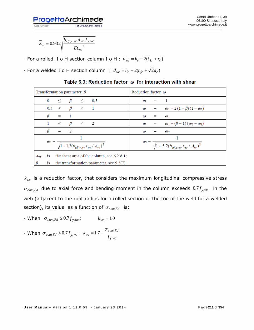
Corso Umberto I, 39 96100 Siracusa-Italy
www.progettoarchimede.it
U s e r M a n u a l – V e r s i o n 1 . 1 1 . 0 . 5 9 - J a n u a r y 2 3 2 0 1 4 P a g e 211 of 354
2
,,,932.0
wc
wcywcwcceffp
Et
fdb
- For a rolled I o H section column I o H : )(2 cfccwc rthd
- For a welded I o H section column : )2(2 cfccwc athd
wck is a reduction factor, that considers the maximum longitudinal compressive stress
Edcom, due to axial force and bending moment in the column exceeds wcyf ,7.0 in the
web (adjacent to the root radius for a rolled section or the toe of the weld for a welded
section), its value as a function of Edcom, is:
- When wcyEdcom f ,, 7.0 : 0.1wck
- When wcyEdcom f ,, 7.0 : wcy
Edcomwc
fk
,
,7.1

Corso Umberto I, 39 96100 Siracusa-Italy
www.progettoarchimede.it
U s e r M a n u a l – V e r s i o n 1 . 1 1 . 0 . 5 9 - J a n u a r y 2 3 2 0 1 4 P a g e 212 of 354
The compressive stress is:
wceff
EdwccEdcom
tb
F ,,,
While the force on the compression web beam is:
2
,,,,
EdbEdbEdwcc
N
z
MF

Corso Umberto I, 39 96100 Siracusa-Italy
www.progettoarchimede.it
U s e r M a n u a l – V e r s i o n 1 . 1 1 . 0 . 5 9 - J a n u a r y 2 3 2 0 1 4 P a g e 213 of 354
3.10.8.2 Stiffened Column web panel
If the minimum design resistance of an unstiffened column web, subjected to a
“column –sway” buckling mode illustrated in Figure 6,7, is due to its buckling, should
normally be prevented by appropriate constructional stiffeners.
To increase the design resistance of the column web in transverse compression, in
order may be used: supplementary web plates, transverse stiffeners, diagonal
stiffeners.
Increase of design resistance due to transverse and diagonal stiffeners
When there are transverse stiffeners on the column web in compression zone,
increases the design resistance in compression that should be taken as similar
to shear added resistance on the web column RdwpV , , in this case the
compression design resistance on the web column is increased (similarly the
shear resistance in the column web) with:
s
Rdfcpl
Rdaddwpd
MV
,,
,,
4 but should be
s
RdstplRdfcpl
Rdaddwpd
MMV
,,,,
,,
22
For the meaning of the values see the shear verification of column web.
When we use transverse stiffeners, the design resistance in compression of

Corso Umberto I, 39 96100 Siracusa-Italy
www.progettoarchimede.it
U s e r M a n u a l – V e r s i o n 1 . 1 1 . 0 . 5 9 - J a n u a r y 2 3 2 0 1 4 P a g e 214 of 354
column web should be determined in according with EN 1993-1-1.
Given the geometry of the diagonal stiffeners, the design plastic normal stress
of single plate is:
0
,
,
diagydiag
diagpl
fAN
That should be greater than the force transmitted by beam flange
cos/,z
MN Ed
diagpl
Where
EdM is the calculation moment transmitted by a single beam
c
b
h
harctan is the angle that the diagonal forms with the axis parallel to the
beam flange
cb hh e are respectively the beam width and the length column
The design shear resistance of column web panel RdwpV , may be increased by
cos,,, diagplRdaddwp NV
The calculation resistance with stiffeners is
RdaddwpRdwccRdwcc VFF ,,,,,,
When the web column is reinforced by adding the supplementary web plate, should be
respected the following mechanical and geometrical sizes:
- The steel grade of the supplementary web plate should be equal to that of the
column;
- The width sb should be such that the supplementary web plate extends at least
to the toe of the root radius with of plate column or of the weld (fig. 6.5);
- The length sl should be such that the supplementary web plate extends
throughout the effective width of the web in tension and compression, see Figure
6.5;

Corso Umberto I, 39 96100 Siracusa-Italy
www.progettoarchimede.it
U s e r M a n u a l – V e r s i o n 1 . 1 1 . 0 . 5 9 - J a n u a r y 2 3 2 0 1 4 P a g e 215 of 354
- The thickness st of the supplementary web plate should be not less than the
column web thickness wct .
When there is the supplementary web plate, the effective web thickness to use for
RdwccF ,, calculation is wct5.1 , if is added a single supplementary web plate, wct0.2 if the
supplementary web plates are placed on the double-sided web. The shear web area
resistant vcA for the calculation of should be increased by wcstb
The web resistance increased are cumulative.
The local verification should be satisfied if:
RdwccEdwcc FF ,,,,
3.10.9 Single bolt bearing resistance
The bearing verification for single bolt resistance section is:
2
1,,
M
ubRdb
dtfkF
Where b is
For outer bolts
)1;3
;min(0
1
d
e
f
f
u
ubb
For inner bolts is
)1;4
1
3;min(
0
1 d
p
f
f
u
ubb
While 1k is
For outer bolts
)5.2;7.18.2min(0
21
d
ek
For inner bolts
Corso Umberto I, 39 96100 Siracusa-Italy
www.progettoarchimede.it
U s e r M a n u a l – V e r s i o n 1 . 1 1 . 0 . 5 9 - J a n u a r y 2 3 2 0 1 4 P a g e 216 of 354
)5.2;7.14.1min(0
21
d
pk
Where
uf is the ultimate tensile strength of lower resistant plate
ubf is the bolt ultimate tensile strength
t is minimum thickness of plates connection
0d is hole diameter
For the other sizes definition see figure 3.1

Corso Umberto I, 39 96100 Siracusa-Italy
www.progettoarchimede.it
U s e r M a n u a l – V e r s i o n 1 . 1 1 . 0 . 5 9 - J a n u a r y 2 3 2 0 1 4 P a g e 217 of 354
The bearing verification is made separately on two horizontal and vertical directions
both profile and supported and supporting beam angles. In the verification vertical and
horizontal shear forces acting on local reference system, are combined.
Must be satisfied:
RdbEdb FF ,,

Corso Umberto I, 39 96100 Siracusa-Italy
www.progettoarchimede.it
U s e r M a n u a l – V e r s i o n 1 . 1 1 . 0 . 5 9 - J a n u a r y 2 3 2 0 1 4 P a g e 218 of 354
3.10.10 Resistance of web Column in transverse tension
Verification made in according with EC3 1-8 point 6.2.6.3
Column web in tension and references
3.10.10.1 Unstiffened column web panel
The design resistance of an unstiffened column web subject to transverse tension
should be determined from:
0
,,,
,,M
wcywcwcteff
Rdwct
ftbF
where:
is a reduction factor to allow the possible effects of interaction with shear in the
column web panel according to table 6.3.
The effective width wcteffb ,, of web column in tension is similar to the effective length of
an equivalent T-stub represented by column flange in unstiffened transverse bending.

Corso Umberto I, 39 96100 Siracusa-Italy
www.progettoarchimede.it
U s e r M a n u a l – V e r s i o n 1 . 1 1 . 0 . 5 9 - J a n u a r y 2 3 2 0 1 4 P a g e 219 of 354
effwcteff lb ,,
For the calculation should be taken the smallest value of the effl , generally we
have the maximum value of the tension force in the end bolt, we should be
considered the end bolt row (End bolt-row) tab. 6.4, should be considered as
single bolt not as a group of bolts.
The reduction factor to allow for the possible effects of interaction with shear in the
column web panel should be determined from table 6.3, using the value of wcteffb ,,
determined for the connection considered.
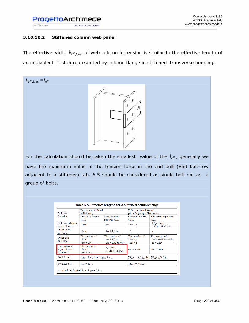
Corso Umberto I, 39 96100 Siracusa-Italy
www.progettoarchimede.it
U s e r M a n u a l – V e r s i o n 1 . 1 1 . 0 . 5 9 - J a n u a r y 2 3 2 0 1 4 P a g e 220 of 354
3.10.10.2 Stiffened column web panel
The effective width wcteffb ,, of web column in tension is similar to the effective length of
an equivalent T-stub represented by column flange in stiffened transverse bending.
effwcteff lb ,,
For the calculation should be taken the smallest value of the effl , generally we
have the maximum value of the tension force in the end bolt (End bolt-row
adjacent to a stiffener) tab. 6.5 should be considered as single bolt not as a
group of bolts.

Corso Umberto I, 39 96100 Siracusa-Italy
www.progettoarchimede.it
U s e r M a n u a l – V e r s i o n 1 . 1 1 . 0 . 5 9 - J a n u a r y 2 3 2 0 1 4 P a g e 221 of 354
To increase the design resistance of the column web in transverse tension, in order
may be used: supplementary web plates, transverse stiffeners, diagonal stiffeners.
The welds of a diagonal stiffener that connect the column flange should be all over
the length of the reinforcement, with throat section similar to the thickness
reinforcements.
When the web column is reinforced by adding the supplementary web plate, should be
respected the following mechanical and geometrical sizes:
- the steel grade of the supplementary web plate should be equal to that of the
column;
- the width sb should be such that the supplementary web plate extends at least
to the toe of the root radius with of plate column or of the weld (fig. 6.5);
- the length sl should be such that the supplementary web plate extends
throughout the effective width of the web in tension and compression, see Figure
6.5;
- the thickness st of the supplementary web plate should be not less than the
column web thickness wct .
The design tension resistance for one supplementary web plate depends on the throat
thickness of the longitudinal welds connecting the supplementary web plates. The
effective thickness of the web efwt , should be taken as follows:
- When the longitudinal welds are full penetration butt welds with a throat thickness
sta then:
- For one supplementary web plate: wceffw tt 5.1,
- For supplementary web plates both sides: wceffw tt 0.2,

Corso Umberto I, 39 96100 Siracusa-Italy
www.progettoarchimede.it
U s e r M a n u a l – V e r s i o n 1 . 1 1 . 0 . 5 9 - J a n u a r y 2 3 2 0 1 4 P a g e 222 of 354
- When the longitudinal welds are fillet welds with a throat thickness 2
sta then for
either one or two supplementary web plates:
- For steel grades S 235, S 275 e S 355: wceffw tt 4.1,
- For steel grades S 420 e S 460: wceffw tt 3.1,
The resistant shear area vcA of a column web ,in calculating the reduction factor di
should be increased of wcstb .
The local verification should be satisfied if :
RdwctEdwct FF ,,,,
3.10.11 Resistance of column flange in transverse bending
Verification made in according with EC3 1-8 point 6.2.6.4
Column flange in bending and references
3.10.11.1 Unstiffened column flange
The design resistance and failure mode of an unstiffened column flange in transverse
bending, together with the associated bolts in tension, should be taken as similar to
those of an equivalent T-stub (EC3 – 1-8 point 6.2.4), the design resistance for both:
- each individual bolt-row required to resist tension;
Corso Umberto I, 39 96100 Siracusa-Italy
www.progettoarchimede.it
U s e r M a n u a l – V e r s i o n 1 . 1 1 . 0 . 5 9 - J a n u a r y 2 3 2 0 1 4 P a g e 223 of 354
- each group of bolt-rows required to resist tension.
The dimensions mine and m to use for verification in according with EC3 – 1-8 point
6.2.4, should be determined from Figure 6.8.
The effective length of equivalent T-stub flange should be determined the individual
bolt-rows and bolt-group (in accordance with EC3 – 1-8 point 6.2.4.2) from the values
given for each group of bolt-rows in Table 6.4.

Corso Umberto I, 39 96100 Siracusa-Italy
www.progettoarchimede.it
U s e r M a n u a l – V e r s i o n 1 . 1 1 . 0 . 5 9 - J a n u a r y 2 3 2 0 1 4 P a g e 224 of 354
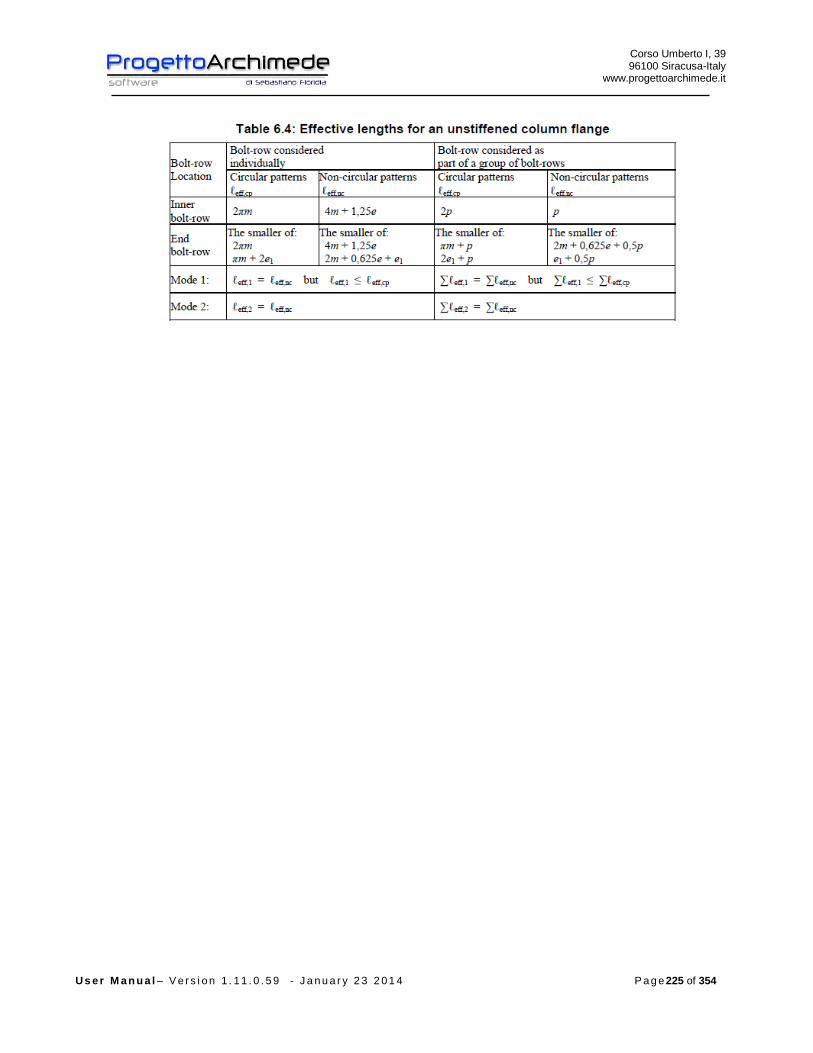
Corso Umberto I, 39 96100 Siracusa-Italy
www.progettoarchimede.it
U s e r M a n u a l – V e r s i o n 1 . 1 1 . 0 . 5 9 - J a n u a r y 2 3 2 0 1 4 P a g e 225 of 354

Corso Umberto I, 39 96100 Siracusa-Italy
www.progettoarchimede.it
U s e r M a n u a l – V e r s i o n 1 . 1 1 . 0 . 5 9 - J a n u a r y 2 3 2 0 1 4 P a g e 226 of 354
Example of failure mechanism unstiffened column flange,
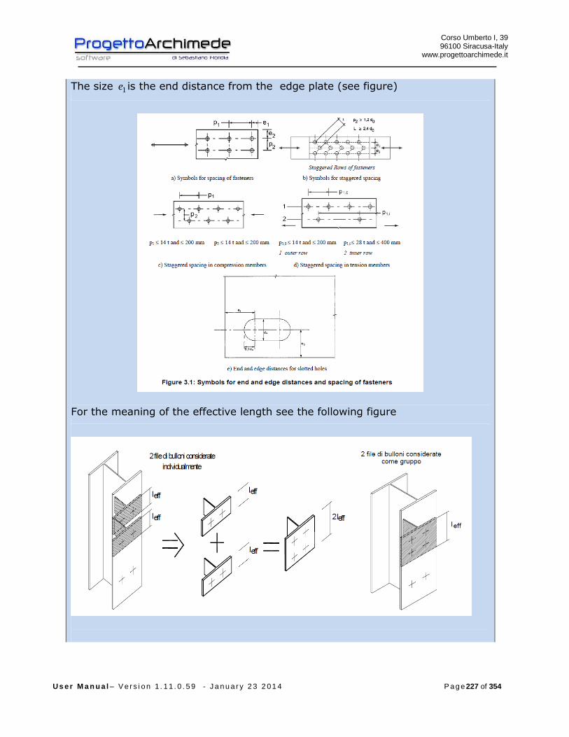
Corso Umberto I, 39 96100 Siracusa-Italy
www.progettoarchimede.it
U s e r M a n u a l – V e r s i o n 1 . 1 1 . 0 . 5 9 - J a n u a r y 2 3 2 0 1 4 P a g e 227 of 354
The size 1e is the end distance from the edge plate (see figure)
For the meaning of the effective length see the following figure

Corso Umberto I, 39 96100 Siracusa-Italy
www.progettoarchimede.it
U s e r M a n u a l – V e r s i o n 1 . 1 1 . 0 . 5 9 - J a n u a r y 2 3 2 0 1 4 P a g e 228 of 354
3.10.11.2 Stiffened column flange
To increase the design resistance of column flange in transverse bending, we use
transverse stiffeners and/or diagonal reinforcements.
The design resistance and the collapse mode of an unstiffened column flange in
transverse bending, is calculated considering also the bolts in tension, considered as a
T-stub (EC3 – 1-8 point 6.2.4), the design resistance is calculated for:
- Each individual bolt-row necessary to endure the tension;
- Each group of bolt row necessary to endure the tension.
The group of bolt rows , both the reinforced side is modeling as an equivalent T-stub
for the flange, see Figure 6.9. The design resistance and the collapse mode is
calculated separately for each equivalent T-stub.
For the size mine e m see Figure 6.8.
The effective length effl an equivalent T-stub flange is determined in according with
EC3 – 1-8 point 6.2.4.2, using the values for each row bolts represented in the table
6.5. The value of should be determined from the Figure 6.11.
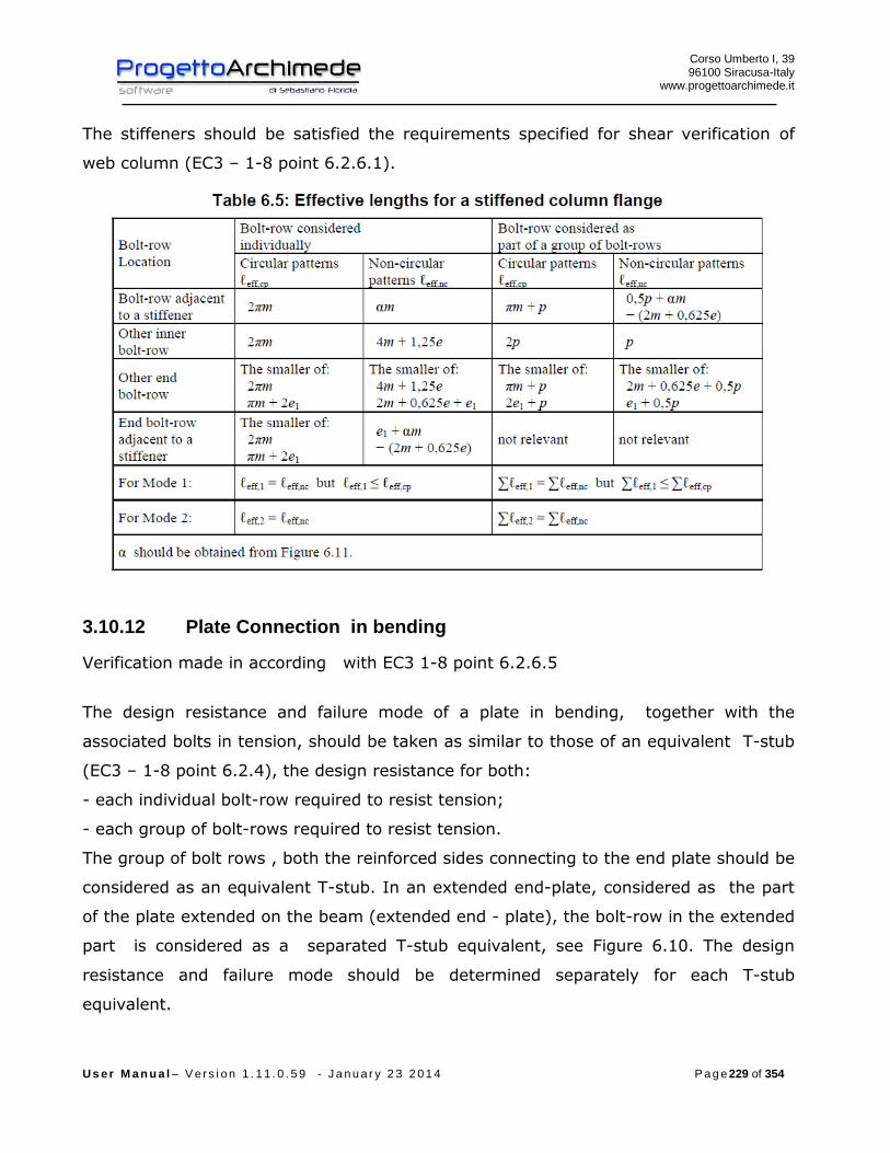
Corso Umberto I, 39 96100 Siracusa-Italy
www.progettoarchimede.it
U s e r M a n u a l – V e r s i o n 1 . 1 1 . 0 . 5 9 - J a n u a r y 2 3 2 0 1 4 P a g e 229 of 354
The stiffeners should be satisfied the requirements specified for shear verification of
web column (EC3 – 1-8 point 6.2.6.1).
3.10.12 Plate Connection in bending
Verification made in according with EC3 1-8 point 6.2.6.5
The design resistance and failure mode of a plate in bending, together with the
associated bolts in tension, should be taken as similar to those of an equivalent T-stub
(EC3 – 1-8 point 6.2.4), the design resistance for both:
- each individual bolt-row required to resist tension;
- each group of bolt-rows required to resist tension.
The group of bolt rows , both the reinforced sides connecting to the end plate should be
considered as an equivalent T-stub. In an extended end-plate, considered as the part
of the plate extended on the beam (extended end - plate), the bolt-row in the extended
part is considered as a separated T-stub equivalent, see Figure 6.10. The design
resistance and failure mode should be determined separately for each T-stub
equivalent.
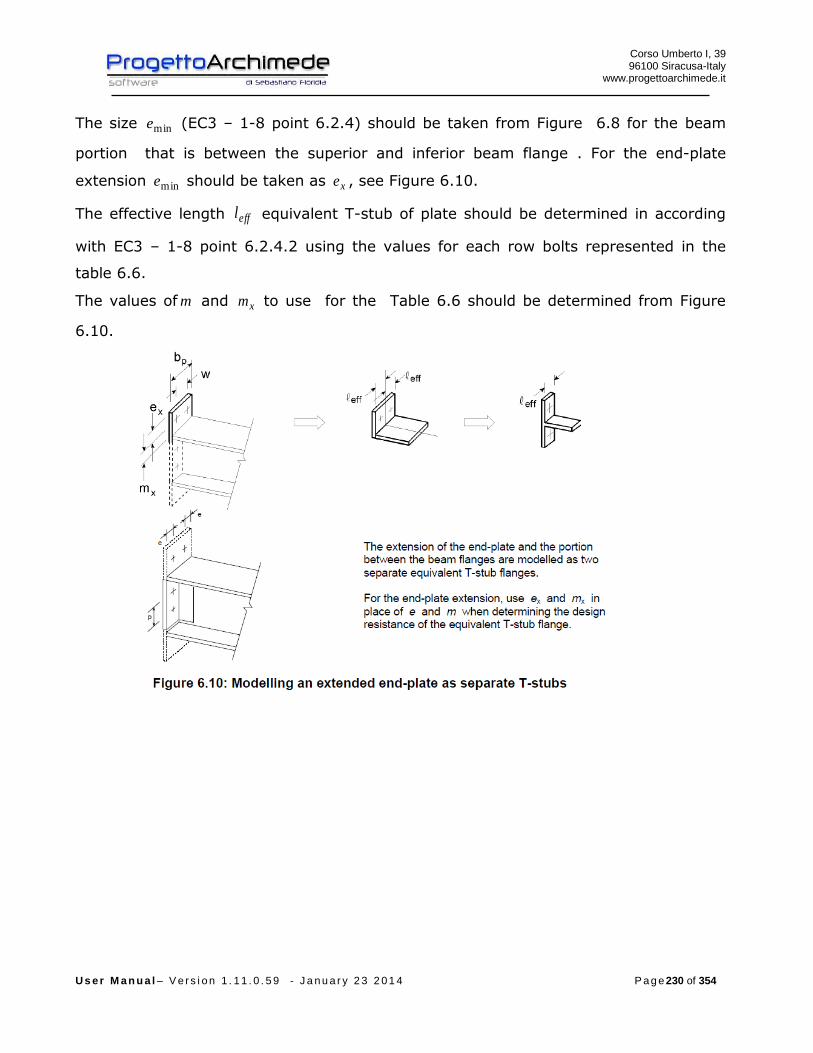
Corso Umberto I, 39 96100 Siracusa-Italy
www.progettoarchimede.it
U s e r M a n u a l – V e r s i o n 1 . 1 1 . 0 . 5 9 - J a n u a r y 2 3 2 0 1 4 P a g e 230 of 354
The size mine (EC3 – 1-8 point 6.2.4) should be taken from Figure 6.8 for the beam
portion that is between the superior and inferior beam flange . For the end-plate
extension mine should be taken as xe , see Figure 6.10.
The effective length effl equivalent T-stub of plate should be determined in according
with EC3 – 1-8 point 6.2.4.2 using the values for each row bolts represented in the
table 6.6.
The values of m and xm to use for the Table 6.6 should be determined from Figure
6.10.

Corso Umberto I, 39 96100 Siracusa-Italy
www.progettoarchimede.it
U s e r M a n u a l – V e r s i o n 1 . 1 1 . 0 . 5 9 - J a n u a r y 2 3 2 0 1 4 P a g e 231 of 354
To note as for the bolt rows between the superior and inferior beam flange the
effl is a vertical size so as the case of effl column flange
While for the extended end plate effl is an horizontal size
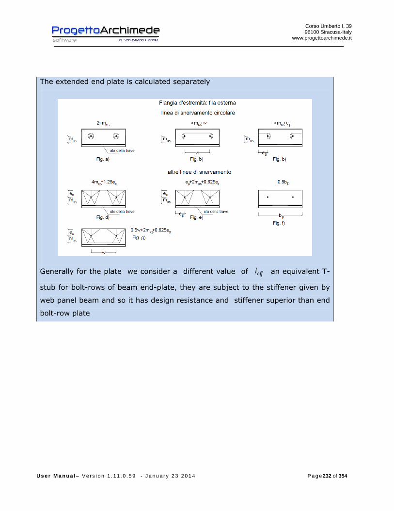
Corso Umberto I, 39 96100 Siracusa-Italy
www.progettoarchimede.it
U s e r M a n u a l – V e r s i o n 1 . 1 1 . 0 . 5 9 - J a n u a r y 2 3 2 0 1 4 P a g e 232 of 354
The extended end plate is calculated separately
Generally for the plate we consider a different value of effl an equivalent T-
stub for bolt-rows of beam end-plate, they are subject to the stiffener given by
web panel beam and so it has design resistance and stiffener superior than end
bolt-row plate

Corso Umberto I, 39 96100 Siracusa-Italy
www.progettoarchimede.it
U s e r M a n u a l – V e r s i o n 1 . 1 1 . 0 . 5 9 - J a n u a r y 2 3 2 0 1 4 P a g e 233 of 354

Corso Umberto I, 39 96100 Siracusa-Italy
www.progettoarchimede.it
U s e r M a n u a l – V e r s i o n 1 . 1 1 . 0 . 5 9 - J a n u a r y 2 3 2 0 1 4 P a g e 234 of 354
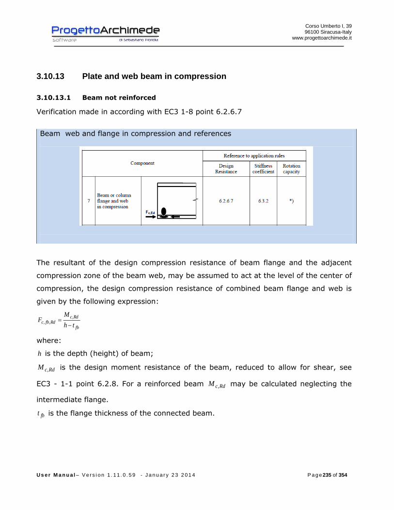
Corso Umberto I, 39 96100 Siracusa-Italy
www.progettoarchimede.it
U s e r M a n u a l – V e r s i o n 1 . 1 1 . 0 . 5 9 - J a n u a r y 2 3 2 0 1 4 P a g e 235 of 354
3.10.13 Plate and web beam in compression
3.10.13.1 Beam not reinforced
Verification made in according with EC3 1-8 point 6.2.6.7
Beam web and flange in compression and references
The resultant of the design compression resistance of beam flange and the adjacent
compression zone of the beam web, may be assumed to act at the level of the center of
compression, the design compression resistance of combined beam flange and web is
given by the following expression:
fb
RdcRdfbc
th
MF
,,,
where:
h is the depth (height) of beam;
RdcM , is the design moment resistance of the beam, reduced to allow for shear, see
EC3 - 1-1 point 6.2.8. For a reinforced beam RdcM , may be calculated neglecting the
intermediate flange.
fbt is the flange thickness of the connected beam.

Corso Umberto I, 39 96100 Siracusa-Italy
www.progettoarchimede.it
U s e r M a n u a l – V e r s i o n 1 . 1 1 . 0 . 5 9 - J a n u a r y 2 3 2 0 1 4 P a g e 236 of 354
Center of compression
If the depth (height) of the beam is more than 600 mm, the design resistance
compression beam contribution should be limited to 20%.
For the RdcM , calculation with shear force, see EC3-1-1 point 6.2.8, we use
reduced moment
0
2
,
,,
4
M
yw
wypl
RdVy
ft
AW
M
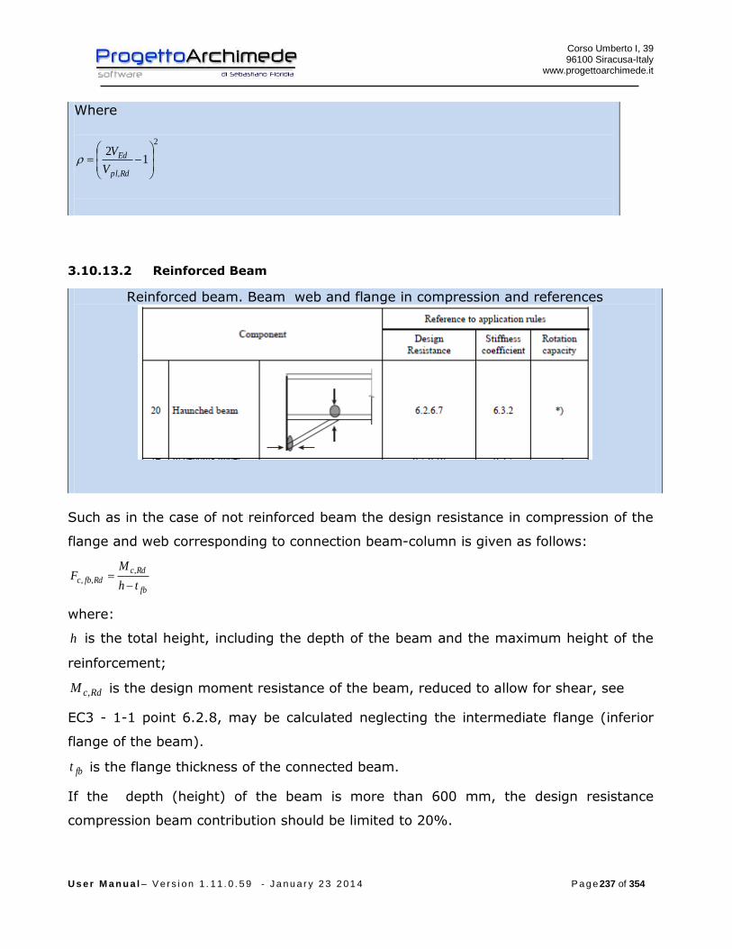
Corso Umberto I, 39 96100 Siracusa-Italy
www.progettoarchimede.it
U s e r M a n u a l – V e r s i o n 1 . 1 1 . 0 . 5 9 - J a n u a r y 2 3 2 0 1 4 P a g e 237 of 354
Where
2
,
12
Rdpl
Ed
V
V
3.10.13.2 Reinforced Beam
Reinforced beam. Beam web and flange in compression and references
Such as in the case of not reinforced beam the design resistance in compression of the
flange and web corresponding to connection beam-column is given as follows:
fb
RdcRdfbc
th
MF
,,,
where:
h is the total height, including the depth of the beam and the maximum height of the
reinforcement;
RdcM , is the design moment resistance of the beam, reduced to allow for shear, see
EC3 - 1-1 point 6.2.8, may be calculated neglecting the intermediate flange (inferior
flange of the beam).
fbt is the flange thickness of the connected beam.
If the depth (height) of the beam is more than 600 mm, the design resistance
compression beam contribution should be limited to 20%.
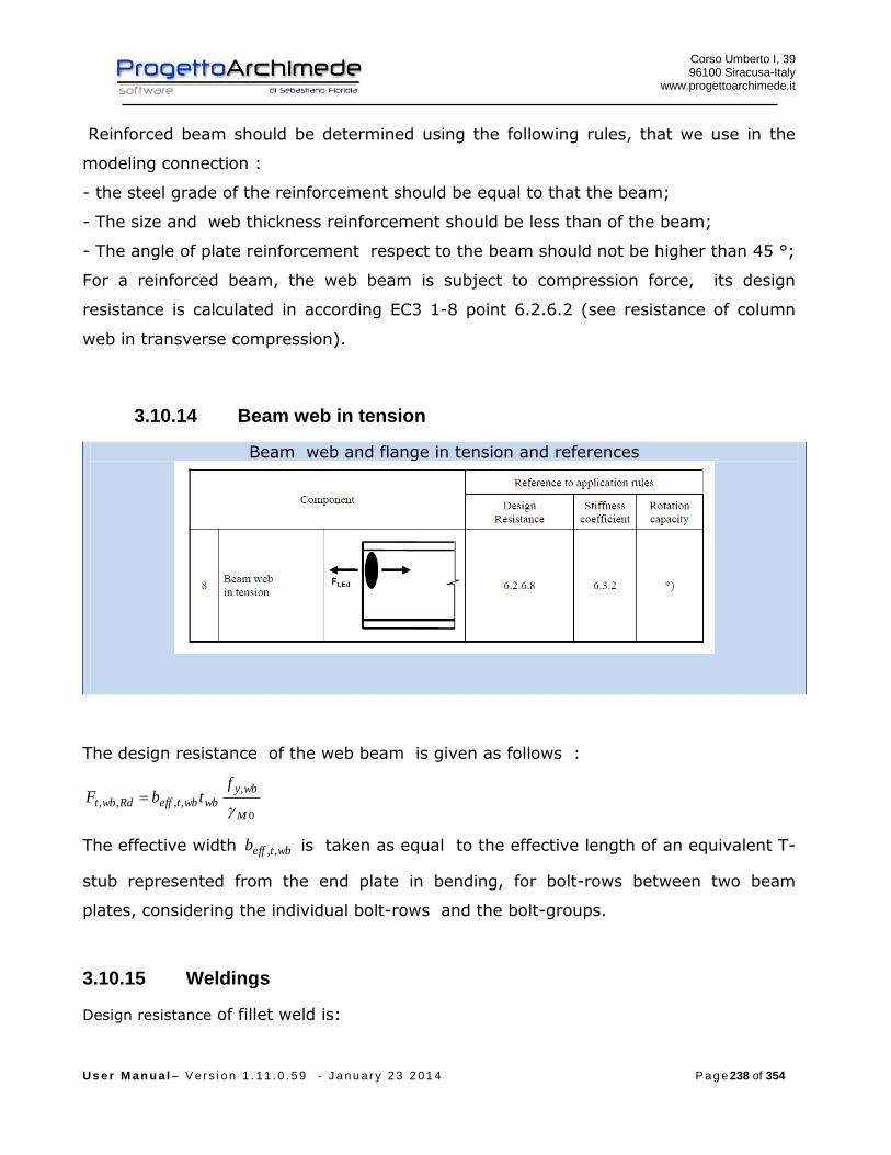
Corso Umberto I, 39 96100 Siracusa-Italy
www.progettoarchimede.it
U s e r M a n u a l – V e r s i o n 1 . 1 1 . 0 . 5 9 - J a n u a r y 2 3 2 0 1 4 P a g e 238 of 354
Reinforced beam should be determined using the following rules, that we use in the
modeling connection :
- the steel grade of the reinforcement should be equal to that the beam;
- The size and web thickness reinforcement should be less than of the beam;
- The angle of plate reinforcement respect to the beam should not be higher than 45 °;
For a reinforced beam, the web beam is subject to compression force, its design
resistance is calculated in according EC3 1-8 point 6.2.6.2 (see resistance of column
web in transverse compression).
3.10.14 Beam web in tension
Beam web and flange in tension and references
The design resistance of the web beam is given as follows :
0
,
,,,,M
wby
wbwbteffRdwbt
ftbF
The effective width wbteffb ,, is taken as equal to the effective length of an equivalent T-
stub represented from the end plate in bending, for bolt-rows between two beam
plates, considering the individual bolt-rows and the bolt-groups.
3.10.15 Weldings
Design resistance of fillet weld is:
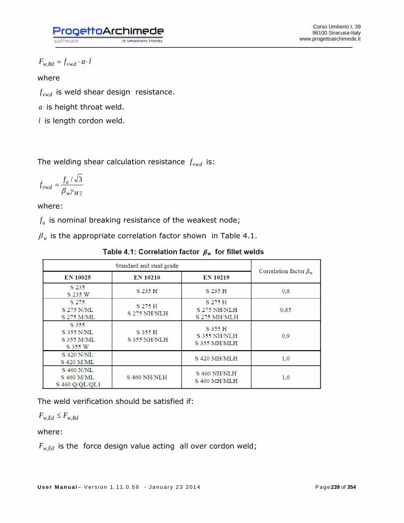
Corso Umberto I, 39 96100 Siracusa-Italy
www.progettoarchimede.it
U s e r M a n u a l – V e r s i o n 1 . 1 1 . 0 . 5 9 - J a n u a r y 2 3 2 0 1 4 P a g e 239 of 354
lafF dvwRdw .,
where
dvwf . is weld shear design resistance.
a is height throat weld.
l is length cordon weld.
The welding shear calculation resistance dvwf . is:
2.
3/
Mw
udvw
ff
where:
uf is nominal breaking resistance of the weakest node;
w is the appropriate correlation factor shown in Table 4.1.
The weld verification should be satisfied if:
RdwEdw FF ,,
where:
EdwF , is the force design value acting all over cordon weld;

Corso Umberto I, 39 96100 Siracusa-Italy
www.progettoarchimede.it
U s e r M a n u a l – V e r s i o n 1 . 1 1 . 0 . 5 9 - J a n u a r y 2 3 2 0 1 4 P a g e 240 of 354
RdwF , is the design resistance of all over weld cordon.
Below are summaries the action of calculation should be considered for the welds
verification.
3.10.15.1 Welds on the supplementary web plates
The shear force on the web plate is transmitted to the supplementary plate by the
welding, the verification should be satisfied if:
bsafFVF dvwRdwEdwpEdw .,.,
and
lsafFVF dvwRdwEdwpEdw .,,,
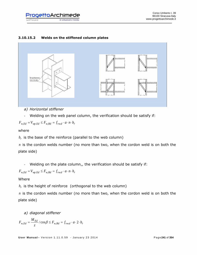
Corso Umberto I, 39 96100 Siracusa-Italy
www.progettoarchimede.it
U s e r M a n u a l – V e r s i o n 1 . 1 1 . 0 . 5 9 - J a n u a r y 2 3 2 0 1 4 P a g e 241 of 354
3.10.15.2 Welds on the stiffened column plates
a) Horizontal stiffener
- Welding on the web panel column, the verification should be satisfy if:
rdvwRdwEdwpEdw bnafFVF .,.,
where
rb is the base of the reinforce (parallel to the web column)
n is the cordon welds number (no more than two, when the cordon weld is on both the
plate side)
- Welding on the plate column,, the verification should be satisfy if:
rdvwRdwEdwpEdw hnafFVF .,.,
Where
rh is the height of reinforce (orthogonal to the web column)
n is the cordon welds number (no more than two, when the cordon weld is on both the
plate side)
a) diagonal stiffener
rdvwRdwEd
Edw bafFz
MF 2cos/ .,,

Corso Umberto I, 39 96100 Siracusa-Italy
www.progettoarchimede.it
U s e r M a n u a l – V e r s i o n 1 . 1 1 . 0 . 5 9 - J a n u a r y 2 3 2 0 1 4 P a g e 242 of 354
Where
rb is the base of reinforce (connection to flange column)
3.10.15.3 Welds beam – connection plate to the column
The plate generally should be bending moment resistant and normal force, welding on
the plate should be checked when:
rdvwRdwEdbEdb
Edept bafFN
z
MF .,
,,,,
2 Where
rb is the length cordon weld on the tension or compressed beam area
The web beam generally should be shear resisting, the welding on the web should be
checked when:
rdvwRdwEdept hafFVF .,,,
where
rh is length cordon weld on the web column
3.10.16 Joint design resistance due to axial force
Verification made in according with EC3 1-8 point 6.2.7.1
The design resistance for pure normal stress RdjN , is calculated as the less value of
single design resistance calculated for the joint ( first considered) , if is compression
force or tension force.
3.10.16.1 Compression design resistance
The compression design resistance RdjN , is the smallest of following values:
- Column Web panel in transverse compression RdwccF ,,2
- Plate and beam web in compression bplN , ( plastic normal stress of the beam).

Corso Umberto I, 39 96100 Siracusa-Italy
www.progettoarchimede.it
U s e r M a n u a l – V e r s i o n 1 . 1 1 . 0 . 5 9 - J a n u a r y 2 3 2 0 1 4 P a g e 243 of 354
3.10.16.2 Tension design resistance
The normal stress tension RdjN , of connection beam-column of a bolted joint with a
plate should be determined by:
RdtrrowRdj FnN ,,
where:
RdtrF , is the effective design resistance of tension of the bolt-row r;
rown is the number of bolt-rows.
The effective design tension resistance RdtrF , for each row-bolt r, taken as single bolt-
rows, is the smaller design tension resistance for a single bolt-row of the following basic
components:
- Column Web in transverse tension RdwctF ,,
- the column flange in transverse bending RdfctF ,,,
- Connection end plate in bending RdeptF ,,,
- Web beam in tension RdwbtF ,,,
- Flange and web beam in tension bplN ,
3.10.17 Shear resistance
Verification made in according EC3 1-8 point 6.2.2
The shear force is totally transferred to the bolts, so the design shear resistance is
connected to the shear resistance.
For a shear connection of class A (EC3 1-8 point 3.4.1) the single bolt shear
resistance should be obtained:
2
,,M
ubvRdv
AfF
If the shear plane is through the thread bolt portion:
- for classes 4.6, 5.6 e 8.8
6.0v
Corso Umberto I, 39 96100 Siracusa-Italy
www.progettoarchimede.it
U s e r M a n u a l – V e r s i o n 1 . 1 1 . 0 . 5 9 - J a n u a r y 2 3 2 0 1 4 P a g e 244 of 354
- for classes 4.8, 5.8 e 10.9
5.0v
If the shear plane is through the not thread bolt portion:
6.0v
For the bolts of connection stressed in tension (see bolts in tension in the case of
bending) their resistance should be reduced by 4.1/4.0 , so:
4.1
4.0,,,,, RdtrvRdv FF
Where
2,,,
M
ubvRdtrv
AfF
is the shear bolt resistance stressed to tension too.
The shear resistance RdjV , of connection beam-column of a bolted joint with plate
should be determined by:
boltn
RdvRdj FV
1
,,
The bearing verification for single bolt is:
2
1,,
M
ubRdb
dtfkF
Where
For end bolts
)1;3
;min(0
1
d
e
f
f
u
ubb
For inner bolts
)1;4
1
3;min(
0
1 d
p
f
f
u
ubb
For end bolts
)5.2;7.18.2min(0
21
d
ek
For inner bolt
Corso Umberto I, 39 96100 Siracusa-Italy
www.progettoarchimede.it
U s e r M a n u a l – V e r s i o n 1 . 1 1 . 0 . 5 9 - J a n u a r y 2 3 2 0 1 4 P a g e 245 of 354
)5.2;7.14.1min(0
21
d
pk
Without shear force however should be considered a shear force equal to 2,5% of
the normal force of weaker section.
3.10.18 Bending force Resistance
Verification made in according with EC3 1-8 point 6.2.7.2
The design moment resistance in bending of a bolted joint with an end plate
connection that has an individual bolt-row in tension (or if is considered only a bolt-row
in tension) should be calculated as shown in Figure 6.15 (c).
The design moment resistance of a bolted joint with a plate with more than tension
bolt-rows should be determined as shown in 6.2.7.2.
For compression center see Figure 6.15.

Corso Umberto I, 39 96100 Siracusa-Italy
www.progettoarchimede.it
U s e r M a n u a l – V e r s i o n 1 . 1 1 . 0 . 5 9 - J a n u a r y 2 3 2 0 1 4 P a g e 246 of 354

Corso Umberto I, 39 96100 Siracusa-Italy
www.progettoarchimede.it
U s e r M a n u a l – V e r s i o n 1 . 1 1 . 0 . 5 9 - J a n u a r y 2 3 2 0 1 4 P a g e 247 of 354
The moment of calculation should be taken as not less than a moment equal to 25% of
plastic moment of the weaker section, if the action is less.
The design moment resistance RdjM , of bolted joint beam- to-column with an end-
plate may be determined from:
r
RdtrrRdj FhM ,,
where:
RdtrF , is the effective design resistance of tension calculation of bolt-row r;
rh is the distance from bolt-row r from center of compression;
r is the bolt-row number
NOTE: The bolt-rows are numerated from farther bolt-row from center of
compression.
The center of compression should be assumed to be in line with the center of the
compression flange of the connected member.
The effective design tension resistance RdtrF , for each bolt-row should be determined
in sequence, from bolt-rows number 1, that is from farther bolt-row from center of
compression, then proceeding to row 2, ecc.
When determining the effective design tension resistance RdtrF , of bolt-row r the
effective design tension resistance of all other bolt-rows closer to the center of
compression should be ignored.
The effective design tension resistance RdtrF , of each bolt-row r ,taken as an individual
bolt-row, should be taken as the smallest value of the design tension resistance RdtrF ,
for an individual bolt-row of the following basic components:

Corso Umberto I, 39 96100 Siracusa-Italy
www.progettoarchimede.it
U s e r M a n u a l – V e r s i o n 1 . 1 1 . 0 . 5 9 - J a n u a r y 2 3 2 0 1 4 P a g e 248 of 354
- The column web in transverse tension RdwctF ,,
- The column flange in transverse bending RdfctF ,,,
- The end-plate in bending RdeptF ,,,
- The beam web in tension RdwbtF ,,,
The effective design tension resistance RdtrF , , of bolt-row r, should ,if necessary, be
reduced below the value of RdtrF , to ensure that all bolt-rows up, to and including bolt-
row r, the following conditions are satisfied :
- The total design resistance
Rdwp
Rdtr
VF
,
, ;
- The total design resistance RdtrF , does not exceed the smaller of :
- The design resistance of the column web in compression RdwccF ,,, ;
- The design resistance of the beam web in compression RdfbcF ,,, .
The effective design tension resistance RdtrF , , of bolt-row r, should ,if necessary, be
reduced below the value of RdtrF , , to ensure that the sum of the design resistances
taken for the bolt-rows up and including bolt-row r that form part of the same group
of bolt-rows, does not exceed the design resistance of that group as a whole.
This should be checked for the following basic components:
- The column web in transverse tension RdwctF ,,
- The column flange in transverse bending RdfctF ,,,
- The end-plate in bending RdeptF ,,,
- The beam web in tension RdwbtF ,,,
Corso Umberto I, 39 96100 Siracusa-Italy
www.progettoarchimede.it
U s e r M a n u a l – V e r s i o n 1 . 1 1 . 0 . 5 9 - J a n u a r y 2 3 2 0 1 4 P a g e 249 of 354
3.10.19 Resistance to buckling and tension-bending
Verification made in according with EC3 1-8 point 6.2.7.1
If the axial force EdN on the beam exceed the 5% of the design resistance RdplN , , the
conservative domain should be used is:
1,
,
,
,
Rdj
Edj
Rdj
Edj
N
N
M
M
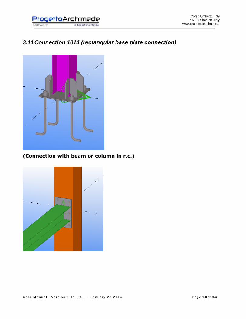
Corso Umberto I, 39 96100 Siracusa-Italy
www.progettoarchimede.it
U s e r M a n u a l – V e r s i o n 1 . 1 1 . 0 . 5 9 - J a n u a r y 2 3 2 0 1 4 P a g e 250 of 354
3.11 Connection 1014 (rectangular base plate connection)
(Connection with beam or column in r.c.)
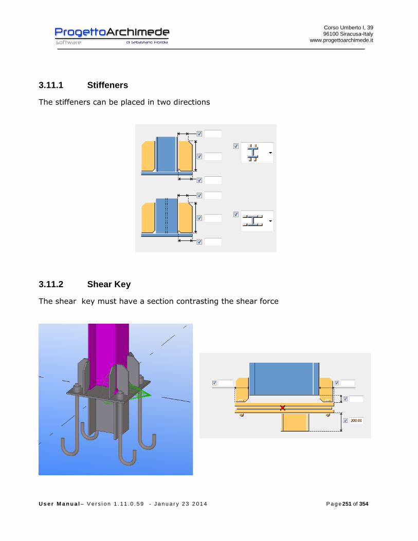
Corso Umberto I, 39 96100 Siracusa-Italy
www.progettoarchimede.it
U s e r M a n u a l – V e r s i o n 1 . 1 1 . 0 . 5 9 - J a n u a r y 2 3 2 0 1 4 P a g e 251 of 354
3.11.1 Stiffeners
The stiffeners can be placed in two directions
3.11.2 Shear Key
The shear key must have a section contrasting the shear force

Corso Umberto I, 39 96100 Siracusa-Italy
www.progettoarchimede.it
U s e r M a n u a l – V e r s i o n 1 . 1 1 . 0 . 5 9 - J a n u a r y 2 3 2 0 1 4 P a g e 252 of 354
3.11.3 Anchor steel bars
The steel bar can be anchored with bolts or bars with stiffeners anchorage
Bolts Straight bar L bar
Hook bar Anchor with washer plate Anchor hammer

Corso Umberto I, 39 96100 Siracusa-Italy
www.progettoarchimede.it
U s e r M a n u a l – V e r s i o n 1 . 1 1 . 0 . 5 9 - J a n u a r y 2 3 2 0 1 4 P a g e 253 of 354
3.11.4 Forces
On the profile we can apply the following forces:
EdN axial force (positive if tension force)
xEdV , shear force parallel to column flange
yEdV , shear force parallel to column axis
xEdM , bending moment all round x axis
The forces can be inserted by Tekla Structures (except xEdV , ), by modeler Midas, by
text file or we can calculate the structure to restore resistance.
If the stresses from Tekla Structures are zero, the actions will have minimum value in
according with EC3 1-8 point 6.2.7.1 (13)
plEd NN 025.0
plyEd VV 025.0,
where the plastic resistances are referred to the column.
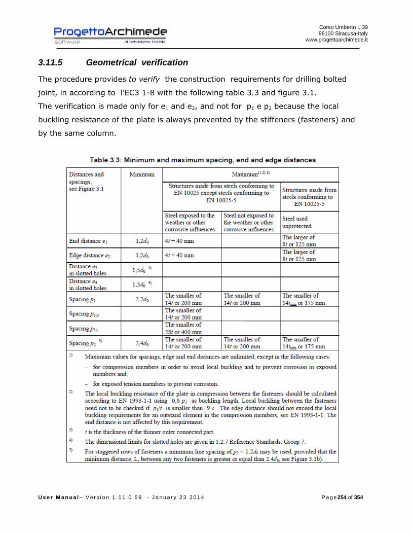
Corso Umberto I, 39 96100 Siracusa-Italy
www.progettoarchimede.it
U s e r M a n u a l – V e r s i o n 1 . 1 1 . 0 . 5 9 - J a n u a r y 2 3 2 0 1 4 P a g e 254 of 354
3.11.5 Geometrical verification
The procedure provides to verify the construction requirements for drilling bolted
joint, in according to l’EC3 1-8 with the following table 3.3 and figure 3.1.
The verification is made only for e1 and e2, and not for p1 e p2 because the local
buckling resistance of the plate is always prevented by the stiffeners (fasteners) and
by the same column.
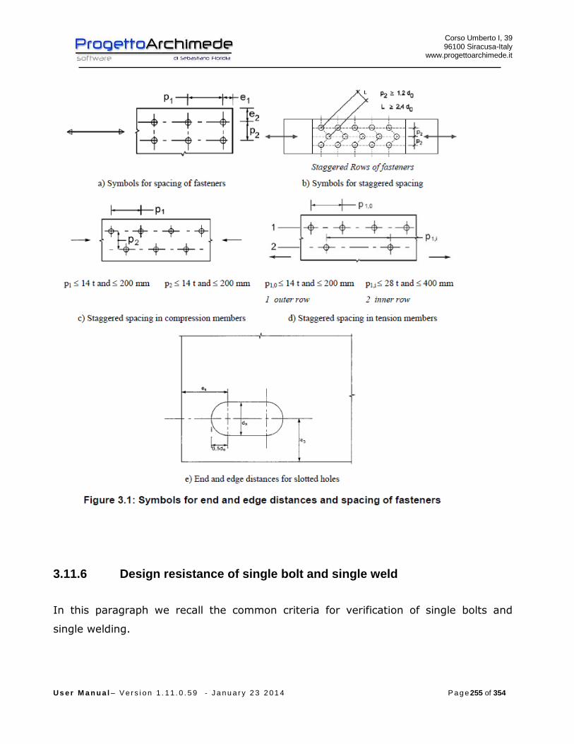
Corso Umberto I, 39 96100 Siracusa-Italy
www.progettoarchimede.it
U s e r M a n u a l – V e r s i o n 1 . 1 1 . 0 . 5 9 - J a n u a r y 2 3 2 0 1 4 P a g e 255 of 354
3.11.6 Design resistance of single bolt and single weld
In this paragraph we recall the common criteria for verification of single bolts and
single welding.

Corso Umberto I, 39 96100 Siracusa-Italy
www.progettoarchimede.it
U s e r M a n u a l – V e r s i o n 1 . 1 1 . 0 . 5 9 - J a n u a r y 2 3 2 0 1 4 P a g e 256 of 354
3.11.6.1 Design resistance at Bolt tensile force
Tensile strength of single bolt is:
2,
9.0
M
subRdt
AfF
Where
sA is the stressed tensile area
ubf is the last tensile of bolt
3.11.6.2 Bolt shear design resistance
For a shear connection (see class A EC3 1-8 point 3.4.1) the single bolt shear strength
design (for a single resistant section) is:
2
,,M
ubvRdv
AfF
If the shear plane is through the threaded bolt portion:
- for classes 4.6, 5.6 e 8.8
6.0v
- for classes 4.8, 5.8 e 10.9
5.0v
If the shear plane is through not threaded bolt portion:
6.0v
While
A is the area of the bolt
ubf is the last bolt tensile stress
3.11.6.3 Design resistance of the weld
Design resistance of fillet weld is:
lafF dvwRdw .,
Where

Corso Umberto I, 39 96100 Siracusa-Italy
www.progettoarchimede.it
U s e r M a n u a l – V e r s i o n 1 . 1 1 . 0 . 5 9 - J a n u a r y 2 3 2 0 1 4 P a g e 257 of 354
dvwf . is weld shear design resistance.
a is the height throat of the weld.
l is the length cordon of the weld.
The welding shear calculation resistance dvwf . is:
2.
3/
Mw
udvw
ff
Where
uf is nominal breaking resistance of the weakest node;
w is the appropriate correlation factor shown in Table 4.1.
Corso Umberto I, 39 96100 Siracusa-Italy
www.progettoarchimede.it
U s e r M a n u a l – V e r s i o n 1 . 1 1 . 0 . 5 9 - J a n u a r y 2 3 2 0 1 4 P a g e 258 of 354
3.11.7 Verifications made
- The verifications made on the joint are the following:
- Shear verification of the connection
RdvEdv FF ,,
RdwEdw FF ,,
1,
,
Rdj
Edj
V
V
- Bearing resistance verification on two horizontal directions on the connection
plate
RdbEdb FF ,,
- Compressive force verification
RdCEdC FF ,,
- Weld column-base plate for bending force
RdwEdw FF ,,
- Flange and column web to compressive force
RdfbcEdfbc FF ,,,,
- Anchor resistance
- RdtEdt FF ,,
- Axial force resistance without moment resistance applied
1,
,
Rdj
Edj
N
N
- Bending force resistance without axial force
1,
,
Rdj
Edj
M
M
- Buckling , we consider the following resistance rule
1,
,
,
,
Rdj
Edj
Rdj
Edj
N
N
M
M
Corso Umberto I, 39 96100 Siracusa-Italy
www.progettoarchimede.it
U s e r M a n u a l – V e r s i o n 1 . 1 1 . 0 . 5 9 - J a n u a r y 2 3 2 0 1 4 P a g e 259 of 354
If the axial force EdN does not exceed the 5% of the plastic axial force RdplN , , is
neglected the coexistence of the axial force and the rule becomes
1,
,
Rdj
Edj
M
M
1.1.8 Verification of shear force
The shear force verification are made with according EC3 1-8 point 6.2.2
Without shear key
In base plates, if no special elements for resisting shear are provided, such as shear
key, the connection shear resistance is the friction resistance between base plate and
grout layer (with compressive force) and anchor bolts resistance.
If in a column there is a compressive force, the design friction resistance between base
plate – grout layer RdfF , is:
EdcdfRdf NCF ,,,
where:
dfC , is the coefficient of friction between base plate and grout layer.
For sand-cement mortar 20.0, dfC
EdcN , is the design value of the normal compressive force in the column.
NOTE: If the column is loaded by a tensile normal force, 0, RdfF .
In a column base the design shear resistance of an anchor bolt RdvbF , should be taken
as the smaller of RdvbF ,,1 and RdvbF ,,2 where:
- RdvbF ,,1 is the design shear resistance of the anchor bolt
-Mb
subbRdvb
AfF
,,2
where:
Corso Umberto I, 39 96100 Siracusa-Italy
www.progettoarchimede.it
U s e r M a n u a l – V e r s i o n 1 . 1 1 . 0 . 5 9 - J a n u a r y 2 3 2 0 1 4 P a g e 260 of 354
ybb f0003.044.0
ybf is the yield strength of the anchor bolt,
with 22 / 640/ 235 mmNfmmN yb
The design shear resistance of the joint RdvF , is
RdvbRdfRdv nFFF ,,,
where:
n is the number of anchor bolts in the base plate.
With Shear key
if special elements for resisting shear are provided, such as shear key, the connection
shear resistance is completely entrusted to the contact surface between the shear key
and the concrete subject to compression .
The design compression resistance RdCF , is:
bhfF jdRdC ,
where:
b is the effective contact area width with shear key and concrete
h is the effective contact area length with shear key and concrete
jdf is the design bearing strength of shear key with concrete
It is assumed that the forces are uniformly distributed to the concrete. The pressure
on the contact surface between the shear key and the foundation must not be superior
the design bearing strength resistance jdf .
The design bearing strength jdf is:
bh
Ff
Rdujjd
where:
j is the foundation material coefficient , which may be taken as 3/2 .
Corso Umberto I, 39 96100 Siracusa-Italy
www.progettoarchimede.it
U s e r M a n u a l – V e r s i o n 1 . 1 1 . 0 . 5 9 - J a n u a r y 2 3 2 0 1 4 P a g e 261 of 354
RduF is the compression design resistance force given in EN 1992, where 0cA is to be
taken as )(bh .
EXTRACT by EC2
6.7 localized forces
(1) In the case of localized forces, we must note the local breaking (see below)
and the cross tensile strength (see point 6.5).
(2) When we have a load uniformly distributed on Ac0 area (see figure 6.29)
the last compression force can be determined as follow:
00
10 3 ccd
c
ccdcRdu Af
A
AfAF
(6.63)
where:
Ac0 is loaded area;
Ac1 is the load maximum diffusion area used for the calculation and which has
an homothetic shape to Ac0.
(3) It is recommended that the diffusion area Ac1 wanted by ultimate
compression force RduF should be satisfied the following conditions:
- the load height diffusion in load direction must be taken as is indicated in
figure 6.29;
- the area diffusion center Ac1 must be on the line of action crossing through the
loading area center Ac0 ;
- if on concrete area act more compression strength, it is recommended that the
diffusion areas aren’t overlapping.
It is recommended that the RduF value is reduced if the load is not uniformly
distributed on area Ac0 or if there are shear force significant.

Corso Umberto I, 39 96100 Siracusa-Italy
www.progettoarchimede.it
U s e r M a n u a l – V e r s i o n 1 . 1 1 . 0 . 5 9 - J a n u a r y 2 3 2 0 1 4 P a g e 262 of 354
(4) It is recommended to provide adequate reinforcements to balance traction
cross forces due to the load effect .
In JFT it considers the minimum value
03 ccdRdu AfF
so:
cdjeffeff
effeffcdj
effeff
Rdujjd f
lb
lbf
lb
Ff 3
3
The verification should be satisfied if
RdCEdv FF ,,
Weld verification
The verification is made considering acting only shear force, is made separately for
connection column-base plate and for connection key shear block – base plate.
It should satisfy:
RdwEdw FF ,,
With

Corso Umberto I, 39 96100 Siracusa-Italy
www.progettoarchimede.it
U s e r M a n u a l – V e r s i o n 1 . 1 1 . 0 . 5 9 - J a n u a r y 2 3 2 0 1 4 P a g e 263 of 354
lafF dvwRdw .,
Where
l is total cordon length
a is throat height.
3.11.8 Resistance to bearing of single bolt
The bearing verification for single bolt resistance section is :
2
1,,
M
ubRdb
dtfkF
Where b is
For outer bolts
)1;3
;min(0
1
d
e
f
f
u
ubb
For inner bolts is
)1;4
1
3;min(
0
1 d
p
f
f
u
ubb
While 1k is
for outer bolts
)5.2;7.18.2min(0
21
d
ek
For inner bolts
)5.2;7.14.1min(0
21
d
pk
Where
uf is the ultimate tensile strength of lower resistant plate
ubf is the bolt ultimate tensile strength
t is minimum thickness of connected plates
0d is the hole diameter

Corso Umberto I, 39 96100 Siracusa-Italy
www.progettoarchimede.it
U s e r M a n u a l – V e r s i o n 1 . 1 1 . 0 . 5 9 - J a n u a r y 2 3 2 0 1 4 P a g e 264 of 354
For the other sizes definition see figure 3.1
The bearing verification is made separately on two horizontal and vertical directions
both profile and supported and supporting beam angles. In the verification vertical and
horizontal shear forces acting on local reference system, are combined.
Must be:
RdbEdb FF ,,
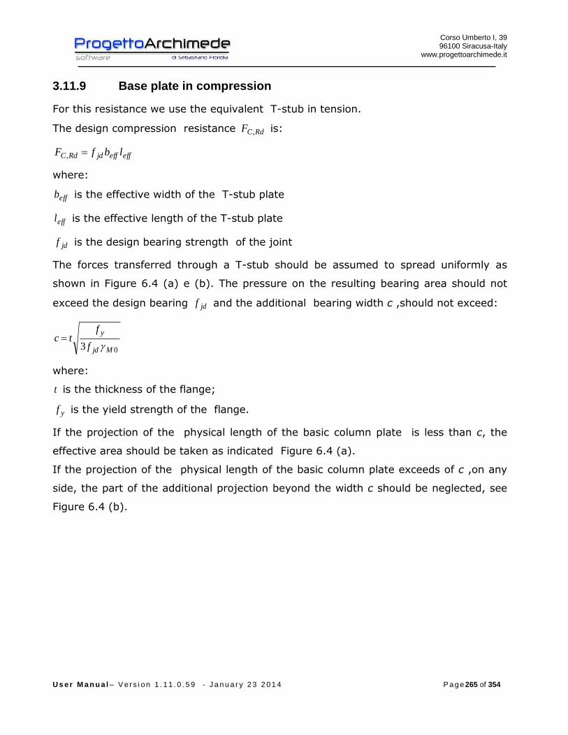
Corso Umberto I, 39 96100 Siracusa-Italy
www.progettoarchimede.it
U s e r M a n u a l – V e r s i o n 1 . 1 1 . 0 . 5 9 - J a n u a r y 2 3 2 0 1 4 P a g e 265 of 354
3.11.9 Base plate in compression
For this resistance we use the equivalent T-stub in tension.
The design compression resistance RdCF , is:
effeffjdRdC lbfF ,
where:
effb is the effective width of the T-stub plate
effl is the effective length of the T-stub plate
jdf is the design bearing strength of the joint
The forces transferred through a T-stub should be assumed to spread uniformly as
shown in Figure 6.4 (a) e (b). The pressure on the resulting bearing area should not
exceed the design bearing jdf and the additional bearing width c ,should not exceed:
03 Mjd
y
f
ftc
where:
t is the thickness of the flange;
yf is the yield strength of the flange.
If the projection of the physical length of the basic column plate is less than c, the
effective area should be taken as indicated Figure 6.4 (a).
If the projection of the physical length of the basic column plate exceeds of c ,on any
side, the part of the additional projection beyond the width c should be neglected, see
Figure 6.4 (b).
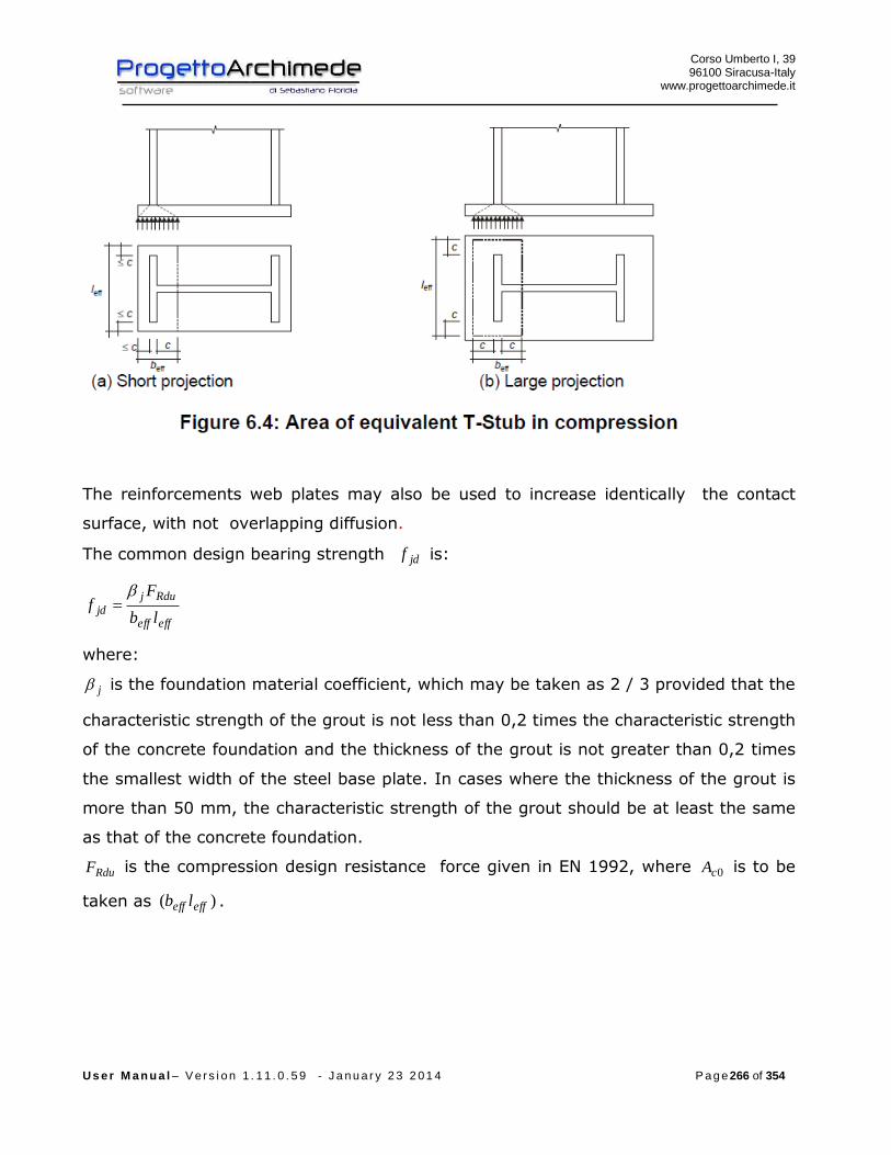
Corso Umberto I, 39 96100 Siracusa-Italy
www.progettoarchimede.it
U s e r M a n u a l – V e r s i o n 1 . 1 1 . 0 . 5 9 - J a n u a r y 2 3 2 0 1 4 P a g e 266 of 354
The reinforcements web plates may also be used to increase identically the contact
surface, with not overlapping diffusion.
The common design bearing strength jdf is:
effeff
Rduj
jdlb
Ff
where:
j is the foundation material coefficient, which may be taken as 2 / 3 provided that the
characteristic strength of the grout is not less than 0,2 times the characteristic strength
of the concrete foundation and the thickness of the grout is not greater than 0,2 times
the smallest width of the steel base plate. In cases where the thickness of the grout is
more than 50 mm, the characteristic strength of the grout should be at least the same
as that of the concrete foundation.
RduF is the compression design resistance force given in EN 1992, where 0cA is to be
taken as )( effeff lb .
Corso Umberto I, 39 96100 Siracusa-Italy
www.progettoarchimede.it
U s e r M a n u a l – V e r s i o n 1 . 1 1 . 0 . 5 9 - J a n u a r y 2 3 2 0 1 4 P a g e 267 of 354
6.7 EXTRACT by EC2
6.7 localized forces
(1) In the case of localized forces, we should be noted the local breaking (see
below) and the cross tensile strength (see point 6.5).
(2) When we have a load uniformly distributed on Ac0 area (see figure 6.29)
the last compression force can be determined as follow:
00
10 3 ccd
c
ccdcRdu Af
A
AfAF
(6.63)
where:
Ac0 is loaded area;
Ac1 is the load maximum diffusion area used for the calculation and which has
an homothetic shape to Ac0.
(3) It is recommended that the diffusion area Ac1 wanted by ultimate
compression force RduF should be satisfied the following conditions:
- the load height diffusion in load direction must be taken as is indicated in
figure 6.29;
- the area diffusion center Ac1 must be on the line of action crossing through the
loading area center Ac0;
- if on concrete area act more compression strength, it is recommended that the
diffusion areas aren’t overlapping.
It is recommended that the RduF value is reduced if the load is not uniformly
distributed on area Ac0 or if there are shear force significant.

Corso Umberto I, 39 96100 Siracusa-Italy
www.progettoarchimede.it
U s e r M a n u a l – V e r s i o n 1 . 1 1 . 0 . 5 9 - J a n u a r y 2 3 2 0 1 4 P a g e 268 of 354
(4) It is recommended to provide adequate reinforcements to balance traction
cross forces due to the load effect .
In JFT it considers the minimum value
03 ccdRdu AfF
so:
cdjeffeff
effeffcdj
effeff
Rdujjd f
lb
lbf
lb
Ff 3
3
Verification
The compression force is transmitted by column flange and is:
2)(
,,,
Edc
fcc
EdcEdC
N
th
MF
so:
RdCEdC FF ,,

Corso Umberto I, 39 96100 Siracusa-Italy
www.progettoarchimede.it
U s e r M a n u a l – V e r s i o n 1 . 1 1 . 0 . 5 9 - J a n u a r y 2 3 2 0 1 4 P a g e 269 of 354
3.11.10 Base plate in bending under tension
The design resistance and collapse mode of a bending base plate, is calculated
considering the design tension resistance of the bolts too, it is considered similar as T-
stub (EC3 – 1-8 point 6.2.4), the design resistance is calculated for:
- the design resistance of an individual bolt row;
- the contribution of each bolt row to design resistance.
The group of bolt rows , on both the reinforced side connected to the end plate
should be considered as separated as an equivalent T-stub. In extended plate,
considered as the extended plate over the beam (extended end - plate), the bolt rows
in extended plate is considered as an equivalent T-stub separated, see Figure 6.10. The
design resistance and the collapse mode is calculated separately for each equivalent T-
stub.
The dimension mine (EC3 – 1-8 point 6.2.4) is taken by Figure 6.8 regarding that part
of plate that is between upper plate and the lower beam. For the extended part of
plate mine is assumed as xe , see Figure 6.10.
The effective length effl an equivalent T-stub flange is determined in according with
EC3 – 1-8 point 6.2.4.2 using the values for each row bolts represented in the table
6.6.
The values of m and xm to be used for the Table 6.6 should be determined from the
Figure 6.10.
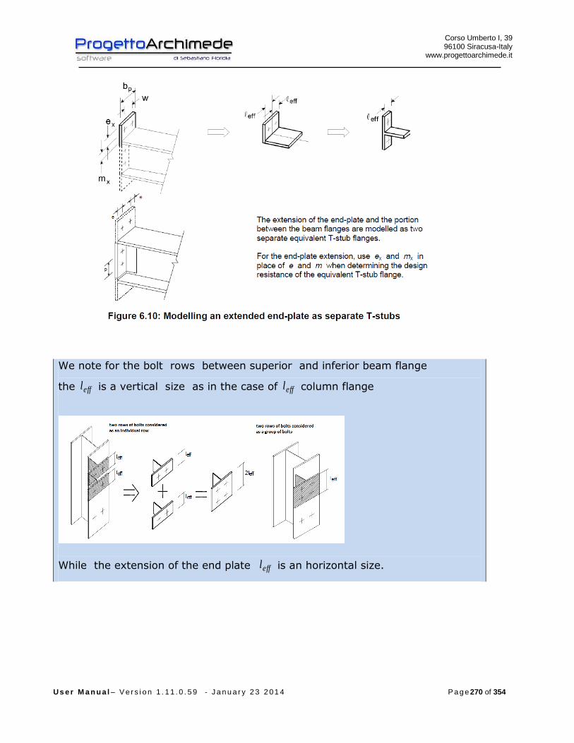
Corso Umberto I, 39 96100 Siracusa-Italy
www.progettoarchimede.it
U s e r M a n u a l – V e r s i o n 1 . 1 1 . 0 . 5 9 - J a n u a r y 2 3 2 0 1 4 P a g e 270 of 354
We note for the bolt rows between superior and inferior beam flange
the effl is a vertical size as in the case of effl column flange
While the extension of the end plate effl is an horizontal size.

Corso Umberto I, 39 96100 Siracusa-Italy
www.progettoarchimede.it
U s e r M a n u a l – V e r s i o n 1 . 1 1 . 0 . 5 9 - J a n u a r y 2 3 2 0 1 4 P a g e 271 of 354
The extension part of the end plate is calculated separately
Generally for the plate we have different value of equivalent member effl to T-
stub equivalent for the bolt rows between the beam plate, these are influenced
of stiffness given by web beam and so it has resistance and stiffness higher than
the extended part of the plate .

Corso Umberto I, 39 96100 Siracusa-Italy
www.progettoarchimede.it
U s e r M a n u a l – V e r s i o n 1 . 1 1 . 0 . 5 9 - J a n u a r y 2 3 2 0 1 4 P a g e 272 of 354

Corso Umberto I, 39 96100 Siracusa-Italy
www.progettoarchimede.it
U s e r M a n u a l – V e r s i o n 1 . 1 1 . 0 . 5 9 - J a n u a r y 2 3 2 0 1 4 P a g e 273 of 354
Weld verification
The verification is made considering acting only bending force.
Should satisfy:
RdwEdw FF ,,
With
lafF dvwRdw .,

Corso Umberto I, 39 96100 Siracusa-Italy
www.progettoarchimede.it
U s e r M a n u a l – V e r s i o n 1 . 1 1 . 0 . 5 9 - J a n u a r y 2 3 2 0 1 4 P a g e 274 of 354
Where
l is the total cordon length
a is the cordon throat height.
3.11.11 Column flange and web in compression
3.11.11.1 Beam not reinforced
Beam web and flange in compression and references
The resultant of the design compression resistance of beam flange and the adjacent
compression zone of the beam web, may be assumed to act at the level of the center of
compression, the design compression resistance of combined beam flange and web is
given by the following expression:
fb
RdcRdfbc
th
MF
,,,
where:
h is the depth (height) of beam;
RdcM , is the design moment resistance of the beam, reduced to allow for shear, see
EC3 - 1-1 point 6.2.8. For a reinforced beam RdcM , may be calculated neglecting the
intermediate flange.
fbt is the flange thickness of the connected beam.

Corso Umberto I, 39 96100 Siracusa-Italy
www.progettoarchimede.it
U s e r M a n u a l – V e r s i o n 1 . 1 1 . 0 . 5 9 - J a n u a r y 2 3 2 0 1 4 P a g e 275 of 354
Center of compression
If the depth (height) of the beam is more than 600 mm, the design resistance
compression beam contribution should be limited to 20%.
For the RdcM , calculation with shear force, see EC3-1-1 point 6.2.8, we use
reduced moment
0
2
,
,,
4
M
yw
wypl
RdVy
ft
AW
M
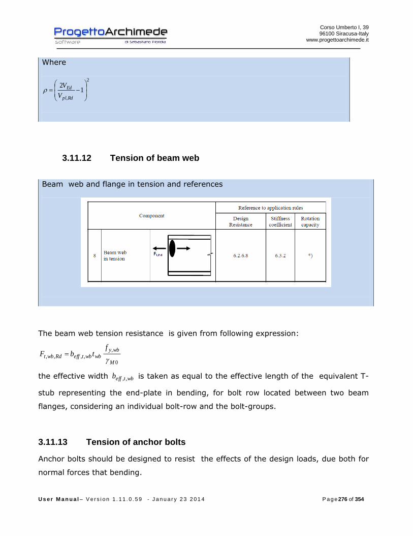
Corso Umberto I, 39 96100 Siracusa-Italy
www.progettoarchimede.it
U s e r M a n u a l – V e r s i o n 1 . 1 1 . 0 . 5 9 - J a n u a r y 2 3 2 0 1 4 P a g e 276 of 354
Where
2
,
12
Rdpl
Ed
V
V
3.11.12 Tension of beam web
Beam web and flange in tension and references
The beam web tension resistance is given from following expression:
0
,
,,,,M
wby
wbwbteffRdwbt
ftbF
the effective width wbteffb ,, is taken as equal to the effective length of the equivalent T-
stub representing the end-plate in bending, for bolt row located between two beam
flanges, considering an individual bolt-row and the bolt-groups.
3.11.13 Tension of anchor bolts
Anchor bolts should be designed to resist the effects of the design loads, due both for
normal forces that bending.

Corso Umberto I, 39 96100 Siracusa-Italy
www.progettoarchimede.it
U s e r M a n u a l – V e r s i o n 1 . 1 1 . 0 . 5 9 - J a n u a r y 2 3 2 0 1 4 P a g e 277 of 354
The lever arm due to bending should be taken as the distance between the barycenter
(centroid) of compression area and the centroid (barycenter) of the bolt group on the
tension side.
The design resistance of the anchor bolts should be taken as the smallest value
between resistance to tension and anchor bolts resistance with concrete.
Single bolt tension resistance is:
2,
9.0
M
subRdt
AfF
Where
sA is the tensile stressed area
ubf is the last tensile bolt strength
The design bond resistance of the concrete and anchor bolts is taken in according with
EN 1992-1-1.
One of the following methods should be used to secure anchor bolts, into foundation:
- A hook (figure 6.14 (a)),
- A washer plate (figure 6.14 (b)),
- Some other appropriate load distributing member embedded in the concrete,
- Some other fixing which has been adequately tested and approved.
When the bolts are provided with a hook, the anchorage length should be such as to
prevent yielding of the bolt . The anchorage length should be calculated in accordance
with EN 1992-1-1. This type of anchorage should not be used for bolts with a yield
strength ybf higher than 2/300 mmN .
When the anchor bolts are provided with a washer plate or other load distributing
member, the design bond resistance of the concrete and steel is not considered. The
whole of the force should be transferred through the load distributing device.
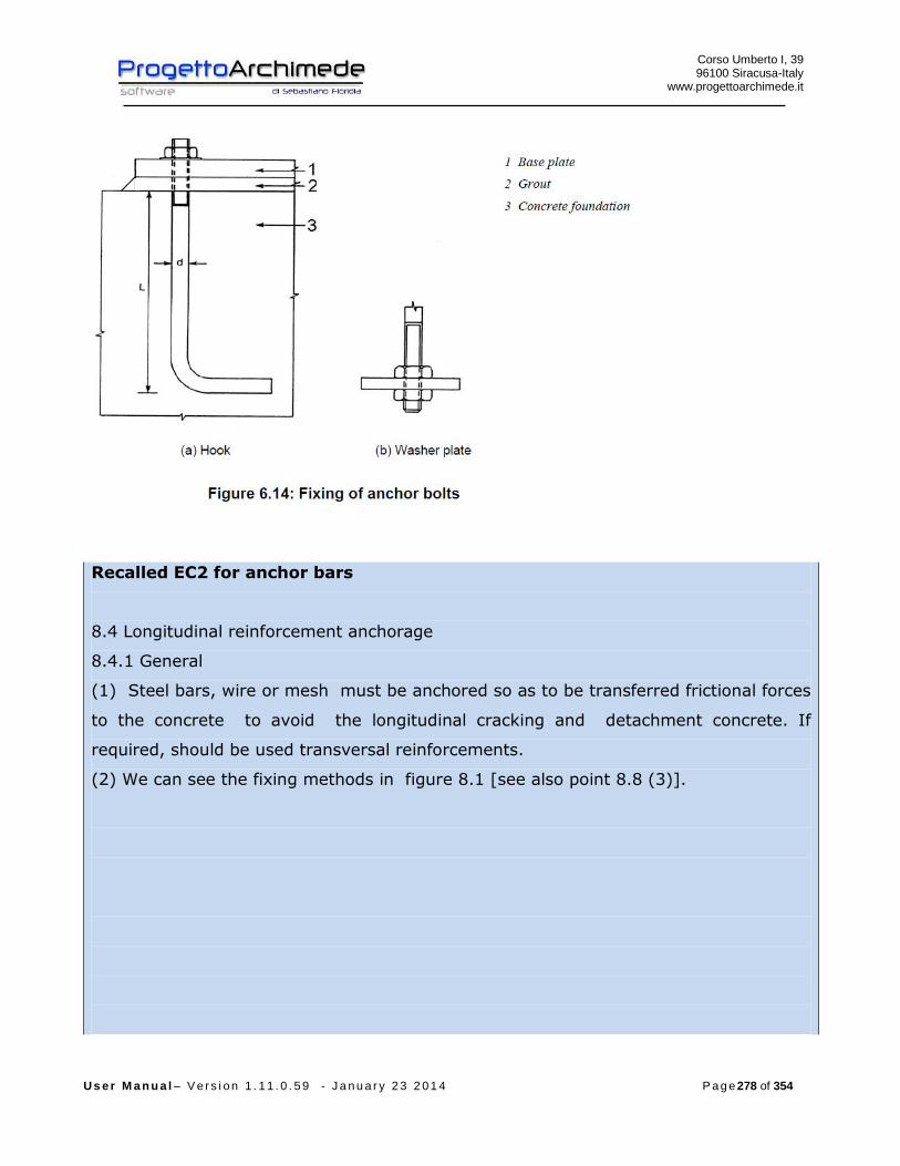
Corso Umberto I, 39 96100 Siracusa-Italy
www.progettoarchimede.it
U s e r M a n u a l – V e r s i o n 1 . 1 1 . 0 . 5 9 - J a n u a r y 2 3 2 0 1 4 P a g e 278 of 354
Recalled EC2 for anchor bars
8.4 Longitudinal reinforcement anchorage
8.4.1 General
(1) Steel bars, wire or mesh must be anchored so as to be transferred frictional forces
to the concrete to avoid the longitudinal cracking and detachment concrete. If
required, should be used transversal reinforcements.
(2) We can see the fixing methods in figure 8.1 [see also point 8.8 (3)].
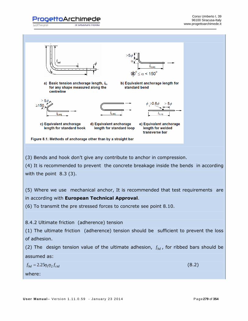
Corso Umberto I, 39 96100 Siracusa-Italy
www.progettoarchimede.it
U s e r M a n u a l – V e r s i o n 1 . 1 1 . 0 . 5 9 - J a n u a r y 2 3 2 0 1 4 P a g e 279 of 354
(3) Bends and hook don’t give any contribute to anchor in compression.
(4) It is recommended to prevent the concrete breakage inside the bends in according
with the point 8.3 (3).
(5) Where we use mechanical anchor, It is recommended that test requirements are
in according with European Technical Approval.
(6) To transmit the pre stressed forces to concrete see point 8.10.
8.4.2 Ultimate friction (adherence) tension
(1) The ultimate friction (adherence) tension should be sufficient to prevent the loss
of adhesion.
(2) The design tension value of the ultimate adhesion, bdf , for ribbed bars should be
assumed as:
ctdbd ff 2125.2 (8.2)
where:

Corso Umberto I, 39 96100 Siracusa-Italy
www.progettoarchimede.it
U s e r M a n u a l – V e r s i o n 1 . 1 1 . 0 . 5 9 - J a n u a r y 2 3 2 0 1 4 P a g e 280 of 354
ctdf is the design value of resistance to concrete tension for point 3.1.6.
(2)P. Due to the increasing fragility of the concrete of higher strength, it is
recommended that the value of fctk 0,05 is limited, for this case, to the relative value
of class C60/75, unless it can verify that the average adhesion resistance exceed;
1 is a ratio related to the quality of adhesion condition and at the bar location during
concreting (see figure 8.2):
11 with condition of “good” adhesion
7.01 in all other cases and for structural elements made with slipform, unless we
can demonstrate that exist “good” conditions of adhesion;
2 it is referred to bar diameter:
2 for mm32
100/)132(2 for mm32
8.4.3 The length of anchor base
(1)P The calculation of anchor length should be calculated considering the type of steel
and the adhesion properties of the bars.

Corso Umberto I, 39 96100 Siracusa-Italy
www.progettoarchimede.it
U s e r M a n u a l – V e r s i o n 1 . 1 1 . 0 . 5 9 - J a n u a r y 2 3 2 0 1 4 P a g e 281 of 354
(2) The anchor length necessary with base rqdbl , , to anchor the force sdsA applied to a
bar in assumption of uniform adhesion tension equal to fbd is:
)/)(4/(, bdsdrqdb fl (8.3)
with sd the design tension corresponding to the point from which is measured the
anchor.
The values of bdf are in point 8.4.2.
(3) The anchor base length, bl , and the design length, bdl of bars should be measured
along the bar axis (see figure 8.1a).
8.4.4 Design anchor length
(1) the design anchor length, bdl , is:
min,,54321 brqdbbd lll (8.4)
with 54321 α α α α α the ratios given in table 8.2:
α1 takes into account the shape of the bars assumed that the concrete cover is
adequate (see figure 8.1);
α2 takes into account the effect of the coating minimum concrete (see figure 8.3);
α3 takes into account the edge effect due to transverse reinforcement;
α4 takes into account the influence of one or more welding transverse bars ( 6.0t )
along the design anchor length bdl (see also point 8.6);
α5 takes into account the transverse force effect to the plan of breaking along the
design anchor length.
The product ( 0.7ααα 532 ): (8.5)
rqdbl , is obtained (8.3);
min,bl is the minimum anchor length if there are not other limitations:
- for tension anchor : mmll bb 100;10;3.0max min,min, (8.6)
- for anchor in compression : mmll bb 100;10;6.0max min,min, (8.7)
(2) For semplicity, alternatively at point 8.4.4 (1), the tension anchor of some shape

Corso Umberto I, 39 96100 Siracusa-Italy
www.progettoarchimede.it
U s e r M a n u a l – V e r s i o n 1 . 1 1 . 0 . 5 9 - J a n u a r y 2 3 2 0 1 4 P a g e 282 of 354
shown in figure 8.1 can be considered as the equivalent anchor length, beql . beql it is
defined in the same figure and can be assumed:
- rqdbl ,1 for the shape that we can see in the figure from 8.1b to 8.1d (for the values of
1 see the table 8.2);
- rqdbl ,4 for the shapes that we can see in the figure 8.1e (for the values of 4 see the
table 8.2);

Corso Umberto I, 39 96100 Siracusa-Italy
www.progettoarchimede.it
U s e r M a n u a l – V e r s i o n 1 . 1 1 . 0 . 5 9 - J a n u a r y 2 3 2 0 1 4 P a g e 283 of 354
3.11.14 Design resistance of column bases with base plates
3.11.14.1 General
Column bases should be of sufficient size stiffness order to resist the axial force,
bending moments and shear forces in columns to their foundations or other
supports without exceeding the load carrying capacity of these supports.
The design bearing strength between the base plate and its support may be
determined on the basis of an uniform distribution of compressive force over the
bearing area. For concrete foundations the bearing area stress should not exceed
the design bearing strength, jdf .
For a column base subject combined axial force and bending, the forces between
the base plate and its support can take one of the following distribution
depending on the relative magnitude of the applied axial force and bending
moment:
- In the case of a dominant compressive axial force, full compression may
develop under both column flanges as shown in Figure 6.18 (a).
- In the case of a dominant tensile force, full tension may develop under both
flanges as shown in Figure 6.18 (b).
- In the case of dominant bending moment compression may develop under one
column flange and tension under the other as shown in Figure 6.18 (c) and
Figure 6.18 (d).
Base plates should be designed using the appropriate methods, only normal
stress or of buckling.
One of the following methods should be used to resist the shear force between
the base plate and its support:
- Frictional design resistance at the joint between the base plate and its support.
- The design shear resistance of the anchor bolts.
- The design shear resistance of the surrounding part of the foundation.
If anchor bolts are used to resist the shear forces between the base plate and its
support, the rupture of the concrete in bearing should also be checked, according
with EN 1992.
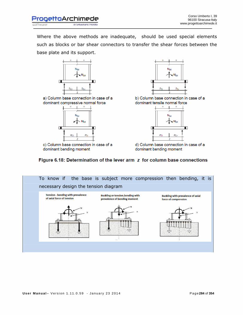
Corso Umberto I, 39 96100 Siracusa-Italy
www.progettoarchimede.it
U s e r M a n u a l – V e r s i o n 1 . 1 1 . 0 . 5 9 - J a n u a r y 2 3 2 0 1 4 P a g e 284 of 354
Where the above methods are inadequate, should be used special elements
such as blocks or bar shear connectors to transfer the shear forces between the
base plate and its support.
To know if the base is subject more compression then bending, it is
necessary design the tension diagram

Corso Umberto I, 39 96100 Siracusa-Italy
www.progettoarchimede.it
U s e r M a n u a l – V e r s i o n 1 . 1 1 . 0 . 5 9 - J a n u a r y 2 3 2 0 1 4 P a g e 285 of 354
3.11.14.2 Column bases subjected to axial force
(1) The design resistance, RdjN , , of a symmetric column base plate subject to an
axial compressive force applied concentrically may be determined by adding
together the individual design resistance RdCF , of the three T-stubs shown in
Figure 6.19 (two T-stubs under the column flanges and one T-stub under the
column web.) The three T-stubs should not overlapping, see Figure 6.19. The
design resistance of each of these T-stubs should be calculated using the method
given in point 6.2.5 of EC3 1- 8.
3.11.14.3 Column bases subject to axial forces and bending moments
(1) The design moment resistance RdjM , of a column base subject to combined
axial force and moment should be determined using the method given in table
6.7, where the contribution of the concrete portion just under the column web
(T-stub 2 di Figure 6.19) to the compressive capacity is omitted.
The following parameters are used in this method:
- RdlTF ,, is the design tension resistance of the left hand side of the joint
- RdrTF ,, is the design tension resistance of the right hand side of the joint
- RdlCF ,, is the design compressive resistance of the left hand side of the joint
- RdrCF ,, is the design compressive resistance of the right hand side of the joint
The design tension resistance RdlTF ,, , of the left side of the joint should be taken
as the smallest values of the design resistance of following basic components:
- the column web in tension under the left column flange RdwctF ,, ;
- the base plate in bending under the left column flange RdpltF ,,

Corso Umberto I, 39 96100 Siracusa-Italy
www.progettoarchimede.it
U s e r M a n u a l – V e r s i o n 1 . 1 1 . 0 . 5 9 - J a n u a r y 2 3 2 0 1 4 P a g e 286 of 354
The design tension resistance RdrTF ,, , of the right side of the joint should be
taken as the smallest values of the design resistance of following basic
components:
- the column web in tension under the right column flange RdwctF ,,
- the base plate in bending under the right column flange RdpltF ,,
The design compressive resistance RdlCF ,, of the left side of the joint should be
taken as the smallest values of the design resistance of following basic
component:
- the concrete in compression under the left column flange RdplcF ,, ;
- the left column flange and web in compression RdfccF ,, .
(5) ) The design compressive resistance RdrCF ,, of the right side of the joint
should be taken as the smallest values of the design resistance of following
basic components:
- the concrete in compression under the right column flange RdplcF ,, ;
- the concrete in compression under the right column flange RdfccF ,, .
For the calculation of lTz , , lCz , , rTz , , rCz , see fig. 6.18.
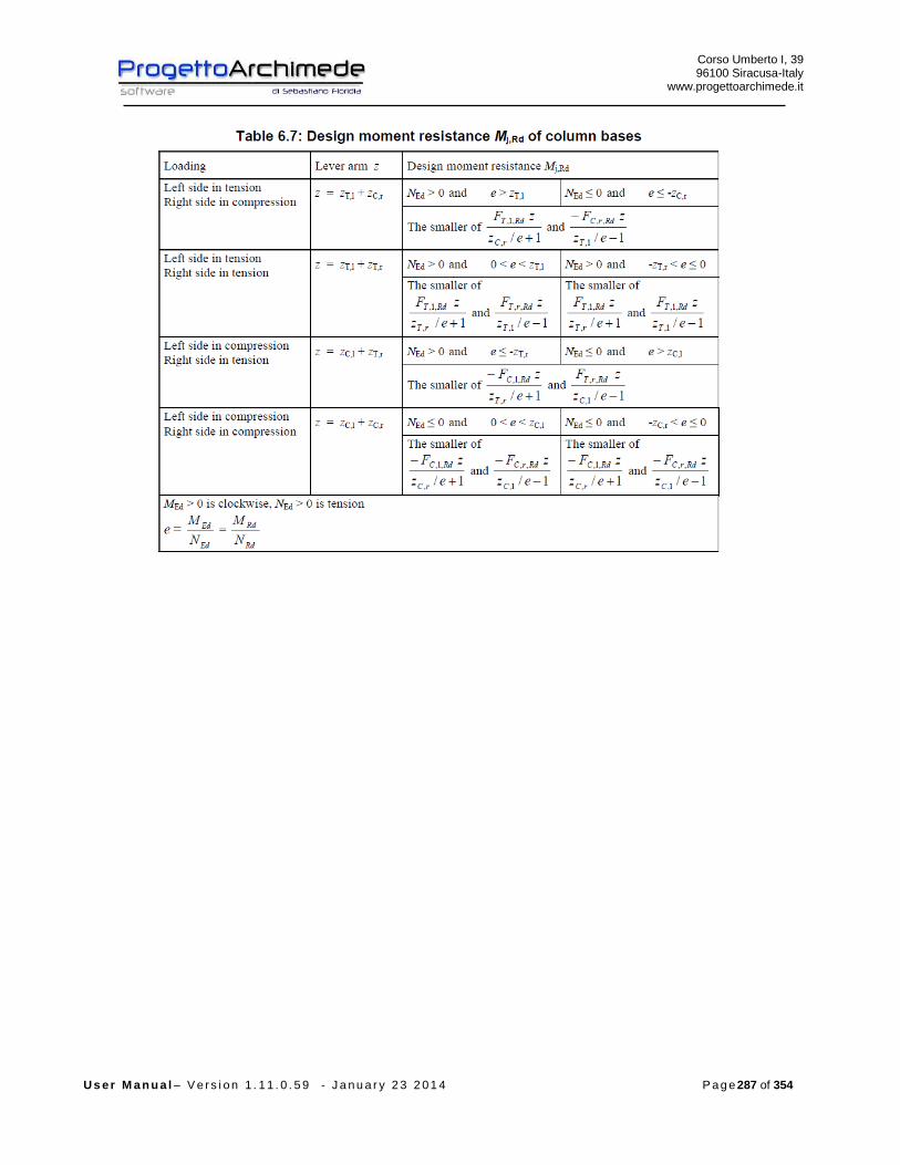
Corso Umberto I, 39 96100 Siracusa-Italy
www.progettoarchimede.it
U s e r M a n u a l – V e r s i o n 1 . 1 1 . 0 . 5 9 - J a n u a r y 2 3 2 0 1 4 P a g e 287 of 354

Corso Umberto I, 39 96100 Siracusa-Italy
www.progettoarchimede.it
U s e r M a n u a l – V e r s i o n 1 . 1 1 . 0 . 5 9 - J a n u a r y 2 3 2 0 1 4 P a g e 288 of 354
3.12 Joint 1052 (connection circular base plate)
(Connection with beam or column in r.c)

Corso Umberto I, 39 96100 Siracusa-Italy
www.progettoarchimede.it
U s e r M a n u a l – V e r s i o n 1 . 1 1 . 0 . 5 9 - J a n u a r y 2 3 2 0 1 4 P a g e 289 of 354
3.12.1 Stiffeners
The stiffeners can be placed along the profile contour
3.12.2 Anchor bolts
The bar can be anchored with bolts or bars with stiffeners anchorage
Bolts Straight bar L bar

Corso Umberto I, 39 96100 Siracusa-Italy
www.progettoarchimede.it
U s e r M a n u a l – V e r s i o n 1 . 1 1 . 0 . 5 9 - J a n u a r y 2 3 2 0 1 4 P a g e 290 of 354
Hook bar Anchor with washer plate
3.12.3 Forces
On the profile we can apply the following forces:
EdN axial force (positive if tension force)
EdV shear force
,EdM bending moment

Corso Umberto I, 39 96100 Siracusa-Italy
www.progettoarchimede.it
U s e r M a n u a l – V e r s i o n 1 . 1 1 . 0 . 5 9 - J a n u a r y 2 3 2 0 1 4 P a g e 291 of 354
The forces can be inserted by Tekla Structures (except xEdV , ), by modeler Midas, by
text file or we can calculate the structure to restore resistance.
If the stresses from Tekla Structures are zero, the actions will have minimum value in
according with EC3 1-8 point 6.2.7.1 (13)
plEd NN 025.0
plEd VV 025.0
Where the plastic resistances are referred to the column .
3.12.4 Geometrical verification
The procedure provides to verify the construction requirements for drilling bolted
joint, in according to l’EC3 1-8 with the following table 3.3 and figure 3.1.
The verification is made only for e1 and e2, and not for p1 e p2 because the local
buckling resistance of the plate is always prevented by the stiffeners and by the same
column.
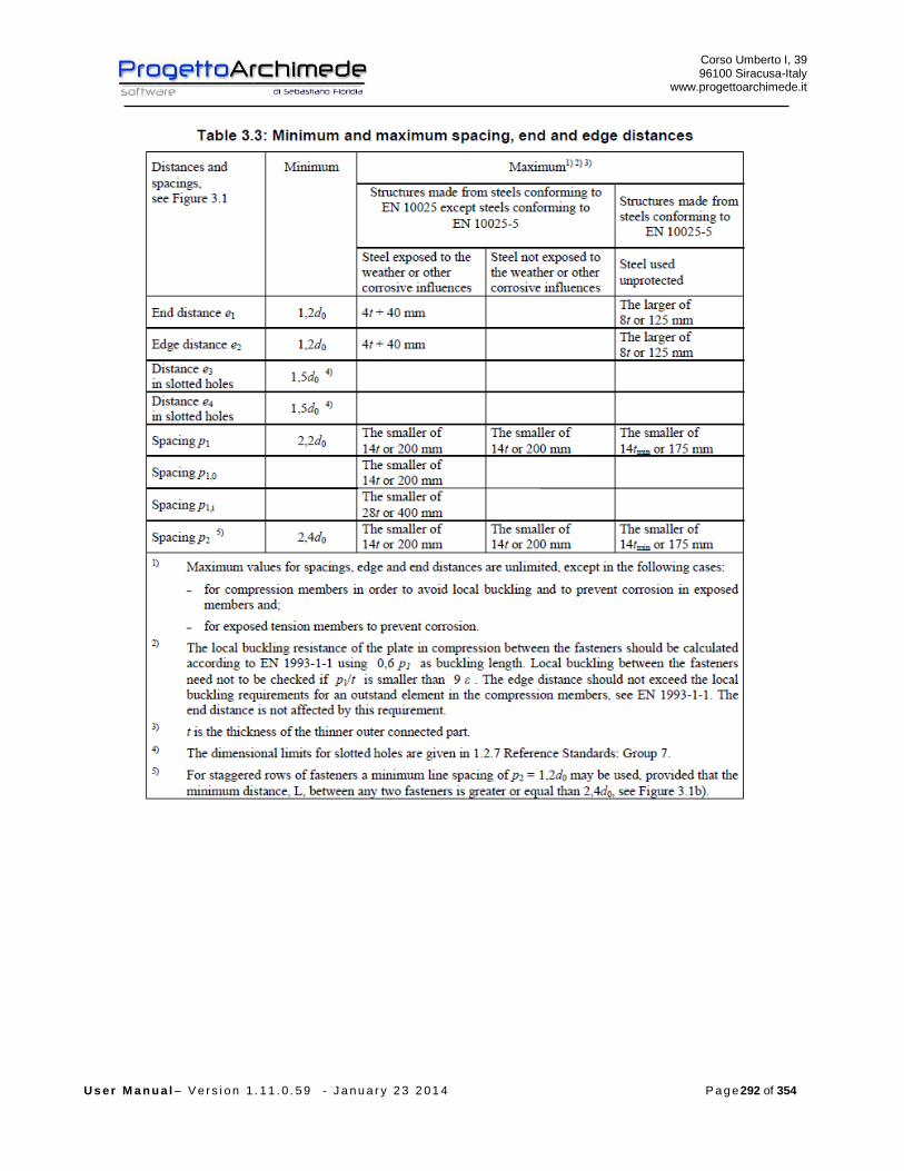
Corso Umberto I, 39 96100 Siracusa-Italy
www.progettoarchimede.it
U s e r M a n u a l – V e r s i o n 1 . 1 1 . 0 . 5 9 - J a n u a r y 2 3 2 0 1 4 P a g e 292 of 354

Corso Umberto I, 39 96100 Siracusa-Italy
www.progettoarchimede.it
U s e r M a n u a l – V e r s i o n 1 . 1 1 . 0 . 5 9 - J a n u a r y 2 3 2 0 1 4 P a g e 293 of 354
3.12.5 Design resistance of single bolt and single weld
In this paragraph we recall the common criteria for verification of single bolts and
single weld.
Corso Umberto I, 39 96100 Siracusa-Italy
www.progettoarchimede.it
U s e r M a n u a l – V e r s i o n 1 . 1 1 . 0 . 5 9 - J a n u a r y 2 3 2 0 1 4 P a g e 294 of 354
3.12.5.1 Design resistance at Bolt tensile force
Tensile strength of single bolt is:
2,
9.0
M
subRdt
AfF
Where
sA is stressed tensile area
ubf is the last tensile of bolt
3.12.5.2 Bolt shear design resistance
For a shear connection (see class A EC3 1-8 point 3.4.1) the single bolt shear strength
design (for a single resistant section) is :
2,,
M
ubvRdv
AfF
If the shear plane is through the threaded bolt portion:
- for classes 4.6, 5.6 e 8.8
6.0v
- for classes 4.8, 5.8 e 10.9
5.0v
If the shear plane is through not threaded bolt portion:
6.0v
while
A is the bolt area
ubf is the last bolt tensile stress
3.12.5.3 Design resistance of Weld
Design resistance of fillet weld is:
lafF dvwRdw .,
Where
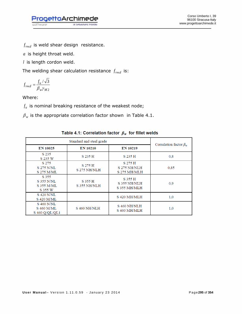
Corso Umberto I, 39 96100 Siracusa-Italy
www.progettoarchimede.it
U s e r M a n u a l – V e r s i o n 1 . 1 1 . 0 . 5 9 - J a n u a r y 2 3 2 0 1 4 P a g e 295 of 354
dvwf . is weld shear design resistance.
a is height throat weld.
l is length cordon weld.
The welding shear calculation resistance dvwf . is:
2.
3/
Mw
udvw
ff
Where:
uf is nominal breaking resistance of the weakest node;
w is the appropriate correlation factor shown in Table 4.1.
Corso Umberto I, 39 96100 Siracusa-Italy
www.progettoarchimede.it
U s e r M a n u a l – V e r s i o n 1 . 1 1 . 0 . 5 9 - J a n u a r y 2 3 2 0 1 4 P a g e 296 of 354
3.12.6 Verifications made
- The verifications made on the joint are the following:
- Shear verification of the connection
- RdvEdv FF ,,
RdwEdw FF ,,
1,
,
Rdj
Edj
V
V
- Bearing resistance verification on two horizontal directions on the connection
plate
RdbEdb FF ,,
- Verification for compressive force
RdCEdC FF ,,
- Weld column-base plate for bending force
RdwEdw FF ,,
- Column section in compression
RdfbcEdfbc FF ,,,,
- Design resistance of anchor
RdtEdt FF ,,
- Axial force resistance without moment resistance applied
1,
,
Rdj
Edj
N
N
- Bending force resistance without axial force
1,
,
Rdj
Edj
M
M
- Buckling , we consider the following resistance rule
1,
,
,
,
Rdj
Edj
Rdj
Edj
N
N
M
M
Corso Umberto I, 39 96100 Siracusa-Italy
www.progettoarchimede.it
U s e r M a n u a l – V e r s i o n 1 . 1 1 . 0 . 5 9 - J a n u a r y 2 3 2 0 1 4 P a g e 297 of 354
If the axial force EdN does not exceed the 5% of the plastic axial force RdplN , , is
neglected the coexistence of the axial force and the rule becomes
1,
,
Rdj
Edj
M
M
3.12.7 Verification of shear force
The shear force verification are made with according EC3 1-8 point 6.2.2
In base plates, if no special elements for resisting shear are provided, such as shear
key, the connection shear resistance is the friction resistance between base plate and
grout layer (with compressive forces) and anchor bolts resistance.
If in a column there is a compressive force, the design friction resistance between base
plate – grout layer RdfF , is:
EdcdfRdf NCF ,,,
where:
is the coefficient of friction between base plate and grout layer.
For sand-cement mortar 20.0, dfC
EdcN , is the design value of the normal compressive force in the column.
NOTE: If the column is loaded by a tensile normal force, 0, RdfF .
In a column base the design shear resistance of an anchor bolt RdvbF , should be taken
as the smaller of RdvbF ,,1 and RdvbF ,,2 where:
- RdvbF ,,1 is the design shear resistance of the anchor bolt
-Mb
subbRdvb
AfF
,,2
where:
ybb f0003.044.0
ybf is the yield strength of the anchor bolt, with 22 / 640/ 235 mmNfmmN yb
Corso Umberto I, 39 96100 Siracusa-Italy
www.progettoarchimede.it
U s e r M a n u a l – V e r s i o n 1 . 1 1 . 0 . 5 9 - J a n u a r y 2 3 2 0 1 4 P a g e 298 of 354
The design shear resistance of the joint RdvF , is
RdvbRdfRdv nFFF ,,,
where:
n is the number of anchor bolts in the base plate.
Verification of the weld
The verification is made considering acting only shear force, is made separately for
connection column-base plate and for connection shear key – base plate.
must satisfy:
RdwEdw FF ,,
with
lafF dvwRdw .,
Where
l is total cordon length
a is throat height.
3.12.8 Bearing resistance for the single bolt
The bearing verification for single bolt resistance section is :
2
1,,
M
ubRdb
dtfkF
Where b is
For outer bolts
)1;3
;min(0
1
d
e
f
f
u
ubb
For inner bolts is
)1;4
1
3;min(
0
1 d
p
f
f
u
ubb
Corso Umberto I, 39 96100 Siracusa-Italy
www.progettoarchimede.it
U s e r M a n u a l – V e r s i o n 1 . 1 1 . 0 . 5 9 - J a n u a r y 2 3 2 0 1 4 P a g e 299 of 354
While 1k is
for outer bolts
)5.2;7.18.2min(0
21
d
ek
For inner bolts
)5.2;7.14.1min(0
21
d
pk
Where
uf is the ultimate tensile strength of lower resistant plate
ubf is the bolt ultimate tensile strength
t is minimum thickness of plates connection
0d is hole diameter
For the other sizes definition see figure 3.1

Corso Umberto I, 39 96100 Siracusa-Italy
www.progettoarchimede.it
U s e r M a n u a l – V e r s i o n 1 . 1 1 . 0 . 5 9 - J a n u a r y 2 3 2 0 1 4 P a g e 300 of 354
The bearing verification is made separately on two horizontal and vertical directions
both profile and supported and supporting beam angles. In the verification vertical and
horizontal shear forces acting on local reference system, are combined.
Must be:
RdbEdb FF ,,
Corso Umberto I, 39 96100 Siracusa-Italy
www.progettoarchimede.it
U s e r M a n u a l – V e r s i o n 1 . 1 1 . 0 . 5 9 - J a n u a r y 2 3 2 0 1 4 P a g e 301 of 354
3.12.9 Base in compression
For this resistance we use the equivalent T-stub in compression in according with EC3
1-8 point 6.2.5.
The design compression resistance RdCF , is:
effeffjdRdC lbfF ,
where:
effb is the effective width of the T-stub flange
effl is the effective length of the T-stub flange
jdf is the design bearing strength of the joint
The forces transferred through a T-stub should be assumed to spread uniformly as
shown in Figure 6.4 (a) e (b). The pressure on the resulting bearing area should not
exceed the design bearing jdf and the additional bearing width c ,should not exceed:
03 Mjd
y
f
ftc
where:
t is the thickness of the flange;
yf is the yield strength of the flange.
If the projection of the physical length of the basic column is less than c, the effective
area should be taken as indicated Figure 6.4 (a).
If the projection of the physical length of the basic column exceeds of c ,on any side,
the part of the additional projection beyond the width c should be neglected, see Figure
6.4 (b).

Corso Umberto I, 39 96100 Siracusa-Italy
www.progettoarchimede.it
U s e r M a n u a l – V e r s i o n 1 . 1 1 . 0 . 5 9 - J a n u a r y 2 3 2 0 1 4 P a g e 302 of 354
The reinforcements web plates may also be used to increase identically the contact
surface, with not overlapping diffusion.
The common design bearing strength jdf is:
effeff
Rduj
jdlb
Ff
dove:
j is the foundation material coefficient, which may be taken as 2 / 3 provided that the
characteristic strength of the grout is not less than 0,2 times the characteristic strength
of the concrete foundation and the thickness of the grout is not greater than 0,2 times
the smallest width of the steel base plate. In cases where the thickness of the grout is
more than 50 mm, the characteristic strength of the grout should be at least the same
as that of the concrete foundation.
RduF is the compression design resistance force given in EN 1992, where 0cA is to be
taken as )( effeff lb .

Corso Umberto I, 39 96100 Siracusa-Italy
www.progettoarchimede.it
U s e r M a n u a l – V e r s i o n 1 . 1 1 . 0 . 5 9 - J a n u a r y 2 3 2 0 1 4 P a g e 303 of 354
EXTRACT by EC2
6.7 localized forces
(1) In the case of localized forces, we should be noted the local breaking (see
below) and the cross tensile strength (see point 6.5).
(2) When we have a load uniformly distributed on Ac0 (see figure 6.29) the last
compression force can be determined as follow:
00
10 3 ccd
c
ccdcRdu Af
A
AfAF
(6.63)
dove:
Ac0 is loaded area;
Ac1 is the load maximum diffusion area used for the calculation and which has
an homothetic shape to Ac0.
(3) It is recommended that the diffusion area Ac1 wanted by ultimate
compression force RduF should be satisfied the following conditions:
- the load height diffusion in load direction must be taken as is indicated in
figure 6.29;
- the area diffusion center Ac1 must be on the line of action crossing through the
loading area center Ac0;
- if on concrete area act more compression strength, it is recommended that the
diffusion areas aren’t overlapping.
It is recommended that the RduF value is reduced if the load is not uniformly
distributed on area Ac0 or if there are shear force significant.

Corso Umberto I, 39 96100 Siracusa-Italy
www.progettoarchimede.it
U s e r M a n u a l – V e r s i o n 1 . 1 1 . 0 . 5 9 - J a n u a r y 2 3 2 0 1 4 P a g e 304 of 354
(4) It is recommended to provide adequate reinforcements to balance traction
cross forces due to the load effect .
In JFT it considers the minimum value
03 ccdRdu AfF
So:
cdjeffeff
effeffcdj
effeff
Rdujjd f
lb
lbf
lb
Ff 3
3
Verification
The compression force is transmitted by column flange and is:
2)(
,,,
Edc
fcc
EdcEdC
N
th
MF
So:
RdCEdC FF ,,

Corso Umberto I, 39 96100 Siracusa-Italy
www.progettoarchimede.it
U s e r M a n u a l – V e r s i o n 1 . 1 1 . 0 . 5 9 - J a n u a r y 2 3 2 0 1 4 P a g e 305 of 354
3.12.10 Connection base plate in bending
EC3 1-8 point 6.2.6.5
The design resistance and collapse mode of a bending base plate, is calculated
considering the design tension resistance of the bolts too, it is considered similar as T-
stub (EC3 – 1-8 point 6.2.4), the design resistance is calculated for:
- the design resistance of an individual bolt row;
- the contribution of each bolt row to design resistance.
The group of bolt rows , both the reinforced side connected to the end plate should be
considered as a separated equivalent T-stub. In extended plate, considered as the
extended plate on the beam (extended end - plate), the bolt rows in extended plate is
considered as an equivalent T-stub separated, see Figure 6.10. The design resistance
and the collapse mode is calculated separately for each equivalent T-stub.
The size mine (EC3 – 1-8 point 6.2.4) is taken by Figure 6.8 regarding that part that is
between upper plate and the lower beam. For the extended part plate mine is assumed
as xe , see Figure 6.10.
The effective length effl an equivalent T-stub flange is determined in according with
EC3 – 1-8 point 6.2.4.2 using the values for each row bolts represented in the table
6.6.
The values of m and xm to be used for the Table 6.6 should be determined from the
Figure 6.10.
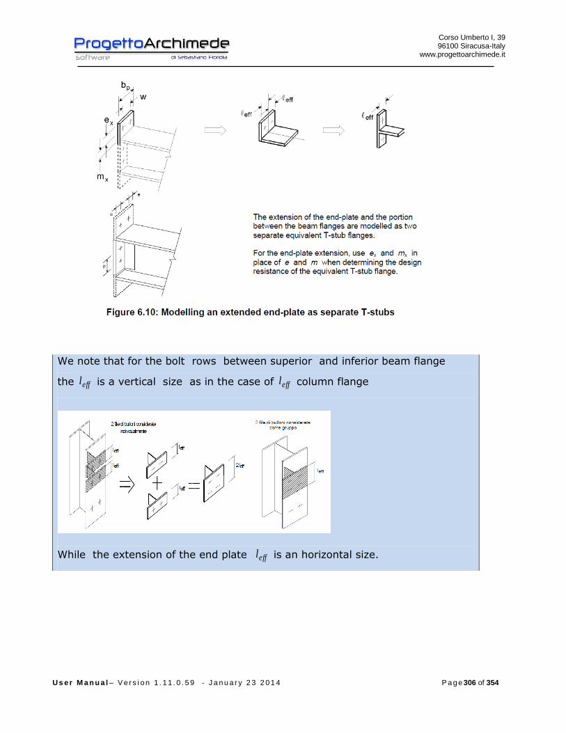
Corso Umberto I, 39 96100 Siracusa-Italy
www.progettoarchimede.it
U s e r M a n u a l – V e r s i o n 1 . 1 1 . 0 . 5 9 - J a n u a r y 2 3 2 0 1 4 P a g e 306 of 354
We note that for the bolt rows between superior and inferior beam flange
the effl is a vertical size as in the case of effl column flange
While the extension of the end plate effl is an horizontal size.
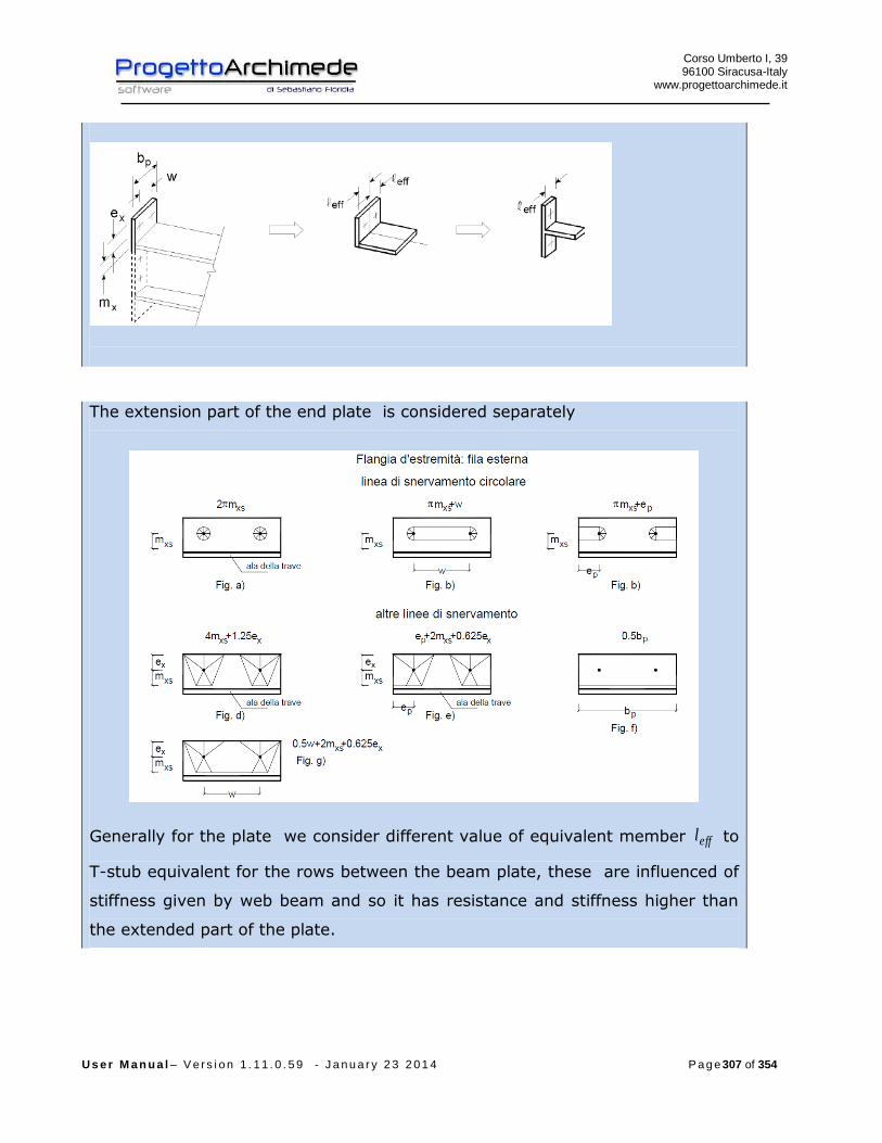
Corso Umberto I, 39 96100 Siracusa-Italy
www.progettoarchimede.it
U s e r M a n u a l – V e r s i o n 1 . 1 1 . 0 . 5 9 - J a n u a r y 2 3 2 0 1 4 P a g e 307 of 354
The extension part of the end plate is considered separately
Generally for the plate we consider different value of equivalent member effl to
T-stub equivalent for the rows between the beam plate, these are influenced of
stiffness given by web beam and so it has resistance and stiffness higher than
the extended part of the plate.

Corso Umberto I, 39 96100 Siracusa-Italy
www.progettoarchimede.it
U s e r M a n u a l – V e r s i o n 1 . 1 1 . 0 . 5 9 - J a n u a r y 2 3 2 0 1 4 P a g e 308 of 354
Verification of the weld
The verification is made considering acting only bending force.
Should satisfy:
RdwEdw FF ,,
With
lafF dvwRdw .,
Where
l is the total cordon length
a is the cordon throat height

Corso Umberto I, 39 96100 Siracusa-Italy
www.progettoarchimede.it
U s e r M a n u a l – V e r s i o n 1 . 1 1 . 0 . 5 9 - J a n u a r y 2 3 2 0 1 4 P a g e 309 of 354
3.12.11 Section of column in compression
3.12.11.1 Beam not reinforced
EC3 1-8 point 6.2.6.7
Beam web and flange in compression and references
The resultant of the design compression resistance of beam flange and the adjacent
compression zone of the beam web, may be assumed to act at the level of the center of
compression, the design compression resistance of combined beam flange and web is
given by the following expression:
fb
RdcRdfbc
th
MF
,,,
where:
h is the depth (height) of beam;
RdcM , is the design moment resistance of the beam, reduced to allow for shear, see
EC3 - 1-1 point 6.2.8. For a reinforced beam RdcM , may be calculated neglecting the
intermediate flange.
fbt is the flange thickness of the connected beam.

Corso Umberto I, 39 96100 Siracusa-Italy
www.progettoarchimede.it
U s e r M a n u a l – V e r s i o n 1 . 1 1 . 0 . 5 9 - J a n u a r y 2 3 2 0 1 4 P a g e 310 of 354
Center of compression
If the depth of the beam is more than 600 mm, the design resistance compression
beam contribution should be limited to 20%.

Corso Umberto I, 39 96100 Siracusa-Italy
www.progettoarchimede.it
U s e r M a n u a l – V e r s i o n 1 . 1 1 . 0 . 5 9 - J a n u a r y 2 3 2 0 1 4 P a g e 311 of 354
For the RdcM , calculation with shear force, see EC3-1-1 point 6.2.8, we use
reduced moment
0
2
,
,,
4
M
yw
wypl
RdVy
ft
AW
M
Where
2
,
12
Rdpl
Ed
V
V
3.12.12 Column section in tension
EC3 1-8 point 6.2.6.8
Beam web and flange in tension and references
The beam web tension resistance is given from following expression:
Corso Umberto I, 39 96100 Siracusa-Italy
www.progettoarchimede.it
U s e r M a n u a l – V e r s i o n 1 . 1 1 . 0 . 5 9 - J a n u a r y 2 3 2 0 1 4 P a g e 312 of 354
0
,
,,,,M
wby
wbwbteffRdwbt
ftbF
the effective width wbteffb ,, is taken as equal to the effective length of the equivalent T-
stub representing the end-plate in bending, for bolt row located between two beam
flanges, considering an individual bolt-row and the bolt-groups.
3.12.13 Anchor bolt in tension
EC3 1-8 point 6.2.6.12
Anchor bolts should be designed to resist the effects of the design loads, due both for
normal forces that bending.
The lever arm due to bending should be taken as the distance between the barycenter
(centroid) of compression area and the centroid (barycenter) of the bolt group on the
tension side.
The design resistance of the anchor bolts should be taken as the smallest value
between resistance to tension and anchor bolts resistance with concrete.
Single bolt tension resistance is:
2,
9.0
M
subRdt
AfF
Where
sA is the tensile stressed area
ubf is the last tensile bolt strength
The design bond resistance of the concrete and anchor bolts is taken in according with
EN 1992-1-1.
One of the following methods should be used to secure anchor bolts, into foundation:
- A hook (figure 6.14 (a)),
- A washer plate (figure 6.14 (b)),
- Some other appropriate load distributing member embedded in the concrete
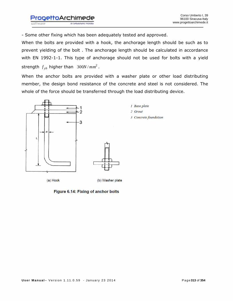
Corso Umberto I, 39 96100 Siracusa-Italy
www.progettoarchimede.it
U s e r M a n u a l – V e r s i o n 1 . 1 1 . 0 . 5 9 - J a n u a r y 2 3 2 0 1 4 P a g e 313 of 354
- Some other fixing which has been adequately tested and approved.
When the bolts are provided with a hook, the anchorage length should be such as to
prevent yielding of the bolt . The anchorage length should be calculated in accordance
with EN 1992-1-1. This type of anchorage should not be used for bolts with a yield
strength ybf higher than 2/300 mmN .
When the anchor bolts are provided with a washer plate or other load distributing
member, the design bond resistance of the concrete and steel is not considered. The
whole of the force should be transferred through the load distributing device.

Corso Umberto I, 39 96100 Siracusa-Italy
www.progettoarchimede.it
U s e r M a n u a l – V e r s i o n 1 . 1 1 . 0 . 5 9 - J a n u a r y 2 3 2 0 1 4 P a g e 314 of 354
Recalled EC2 for anchor bars
8.4 Longitudinal reinforcement anchorage
8.4.1 General
(1) Steel bars, wire or mesh must be anchored so as to be transferred frictional forces
to the concrete to avoid the longitudinal cracking and detachment concrete. If
required, should be used transversal reinforcements.
(2) We can see the fixing methods in figure 8.1 [see also point 8.8 (3)].
(3) Bends and hook don’t give any contribute to anchor in compression.
(4) It is recommended to prevent the concrete breakage inside the bends in according
with the point 8.3 (3).
(5) Where we use mechanical anchor, It is recommended that test requirements are
in according with European Technical Approval.
(6) To transmit the pre stress forces to concrete see point 8.10.
Corso Umberto I, 39 96100 Siracusa-Italy
www.progettoarchimede.it
U s e r M a n u a l – V e r s i o n 1 . 1 1 . 0 . 5 9 - J a n u a r y 2 3 2 0 1 4 P a g e 315 of 354
8.4.2 Ultimate friction (adherence) tension
(1) The ultimate friction (adherence) tension should be sufficient to prevent the loss
of adhesion.
(2) The design tension value of the ultimate adhesion, bdf , for ribbed bars should be
assumed as:
ctdbd ff 2125.2 (8.2)
where:
ctdf is the design value of resistance to concrete tension for point 3.1.6.
(2)P. Due to the increasing fragility of the concrete of higher strength, it is
recommended that the value of fctk 0,05 is limited, for this case, to the relative value
of class C60/75, unless it can verify that the average adhesion resistance exceed;
1 is a ratio related to the quality of adhesion condition and at the bar location during
concreting (see figure 8.2):
11 with condition of “good” adhesion
7.01 in all other cases and for structural elements made with slipform, unless we
can demonstrate that exist “good” conditions of adhesion;
2 it is referred to bar diameter:
2 for mm32
100/)132(2 for mm32
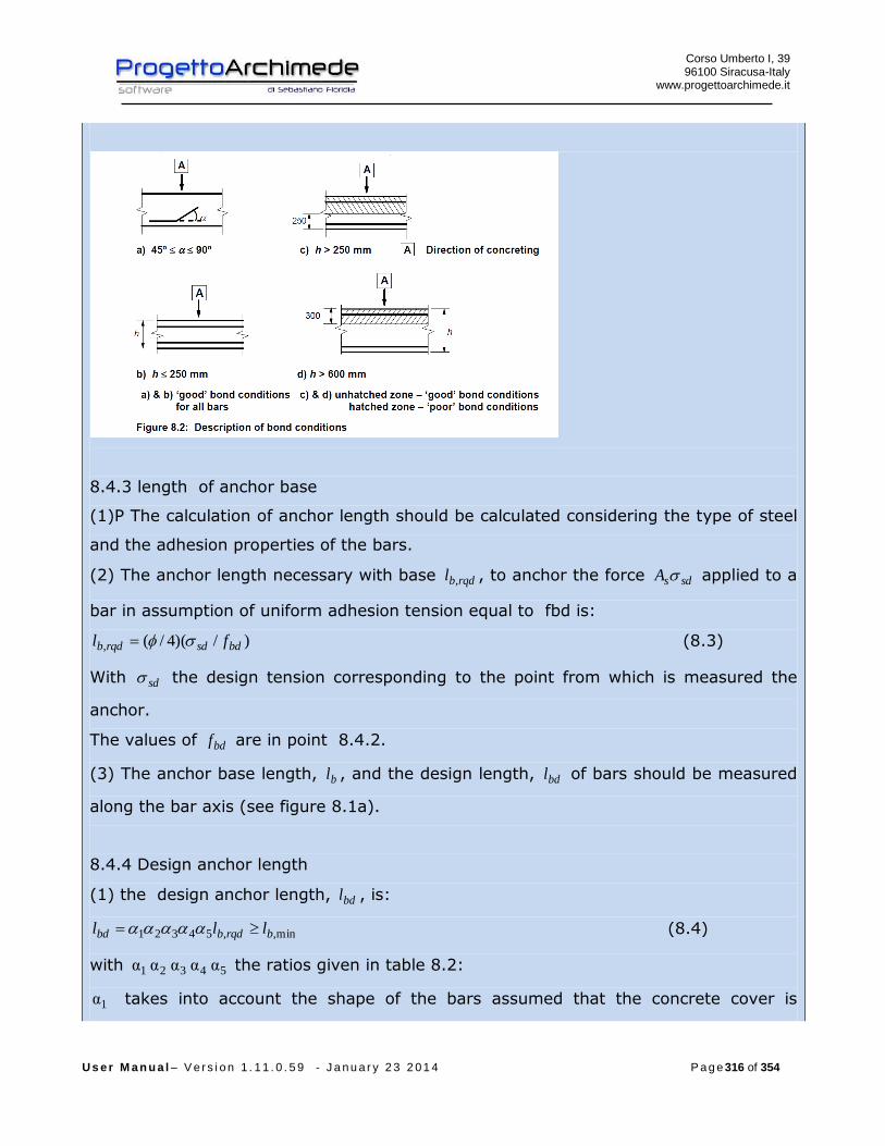
Corso Umberto I, 39 96100 Siracusa-Italy
www.progettoarchimede.it
U s e r M a n u a l – V e r s i o n 1 . 1 1 . 0 . 5 9 - J a n u a r y 2 3 2 0 1 4 P a g e 316 of 354
8.4.3 length of anchor base
(1)P The calculation of anchor length should be calculated considering the type of steel
and the adhesion properties of the bars.
(2) The anchor length necessary with base rqdbl , , to anchor the force sdsA applied to a
bar in assumption of uniform adhesion tension equal to fbd is:
)/)(4/(, bdsdrqdb fl (8.3)
With sd the design tension corresponding to the point from which is measured the
anchor.
The values of bdf are in point 8.4.2.
(3) The anchor base length, bl , and the design length, bdl of bars should be measured
along the bar axis (see figure 8.1a).
8.4.4 Design anchor length
(1) the design anchor length, bdl , is:
min,,54321 brqdbbd lll (8.4)
with 54321 α α α α α the ratios given in table 8.2:
α1 takes into account the shape of the bars assumed that the concrete cover is
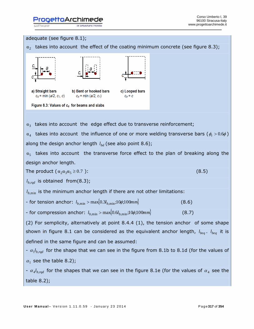
Corso Umberto I, 39 96100 Siracusa-Italy
www.progettoarchimede.it
U s e r M a n u a l – V e r s i o n 1 . 1 1 . 0 . 5 9 - J a n u a r y 2 3 2 0 1 4 P a g e 317 of 354
adequate (see figure 8.1);
α2 takes into account the effect of the coating minimum concrete (see figure 8.3);
α3 takes into account the edge effect due to transverse reinforcement;
α4 takes into account the influence of one or more welding transverse bars ( 6.0t )
along the design anchor length bdl (see also point 8.6);
α5 takes into account the transverse force effect to the plan of breaking along the
design anchor length.
The product ( 0.7ααα 532 ): (8.5)
rqdbl , is obtained from(8.3);
min,bl is the minimum anchor length if there are not other limitations:
- for tension anchor: mmll bb 100;10;3.0max min,min, (8.6)
- for compression anchor: mmll bb 100;10;6.0max min,min, (8.7)
(2) For semplicity, alternatively at point 8.4.4 (1), the tension anchor of some shape
shown in figure 8.1 can be considered as the equivalent anchor length, beql . beql it is
defined in the same figure and can be assumed:
- rqdbl ,1 for the shape that we can see in the figure from 8.1b to 8.1d (for the values of
1 see the table 8.2);
- rqdbl ,4 for the shapes that we can see in the figure 8.1e (for the values of 4 see the
table 8.2);
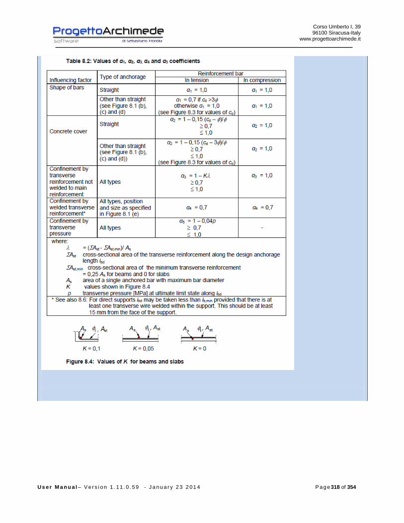
Corso Umberto I, 39 96100 Siracusa-Italy
www.progettoarchimede.it
U s e r M a n u a l – V e r s i o n 1 . 1 1 . 0 . 5 9 - J a n u a r y 2 3 2 0 1 4 P a g e 318 of 354
Corso Umberto I, 39 96100 Siracusa-Italy
www.progettoarchimede.it
U s e r M a n u a l – V e r s i o n 1 . 1 1 . 0 . 5 9 - J a n u a r y 2 3 2 0 1 4 P a g e 319 of 354
3.12.14 Design resistance of column bases with base plates
EC3 1-8 point 6.2.8.1
3.12.14.1 General
Column bases should be of sufficient size stiffness order to resist the axial force,
bending moments and shear forces in columns to their foundations or other
supports, without exceeding the load carrying capacity of these supports.
The design bearing strength between the base plate and its support may be
determined on the basis of an uniform distribution of compressive force over the
bearing area. For concrete foundations the bearing area stress should not exceed
the design bearing strength, jdf .
For a column base subject combined axial force and bending, the forces between
the base plate and its support can take one of the following distribution
depending on the relative magnitude of the applied axial force and bending
moment:
- In the case of a dominant compressive axial force, full compression may
develop under both column flanges as shown in Figure 6.18 (a).
- In the case of a dominant tensile force, full tension may develop under both
flanges as shown in Figure 6.18 (b).
- In the case of dominant bending moment compression may develop under one
column flange and tension under the other as shown in Figure 6.18 (c) and
Figure 6.18 (d).
Base plates should be designed using the appropriate methods, only normal
stress or of buckling.
One of the following methods should be used to resist the shear force between
the base plate and its support:
- Frictional design resistance at the joint between the base plate and its support.
- The design shear resistance of the anchor bolts.
- The design shear resistance of the surrounding part of the foundation.
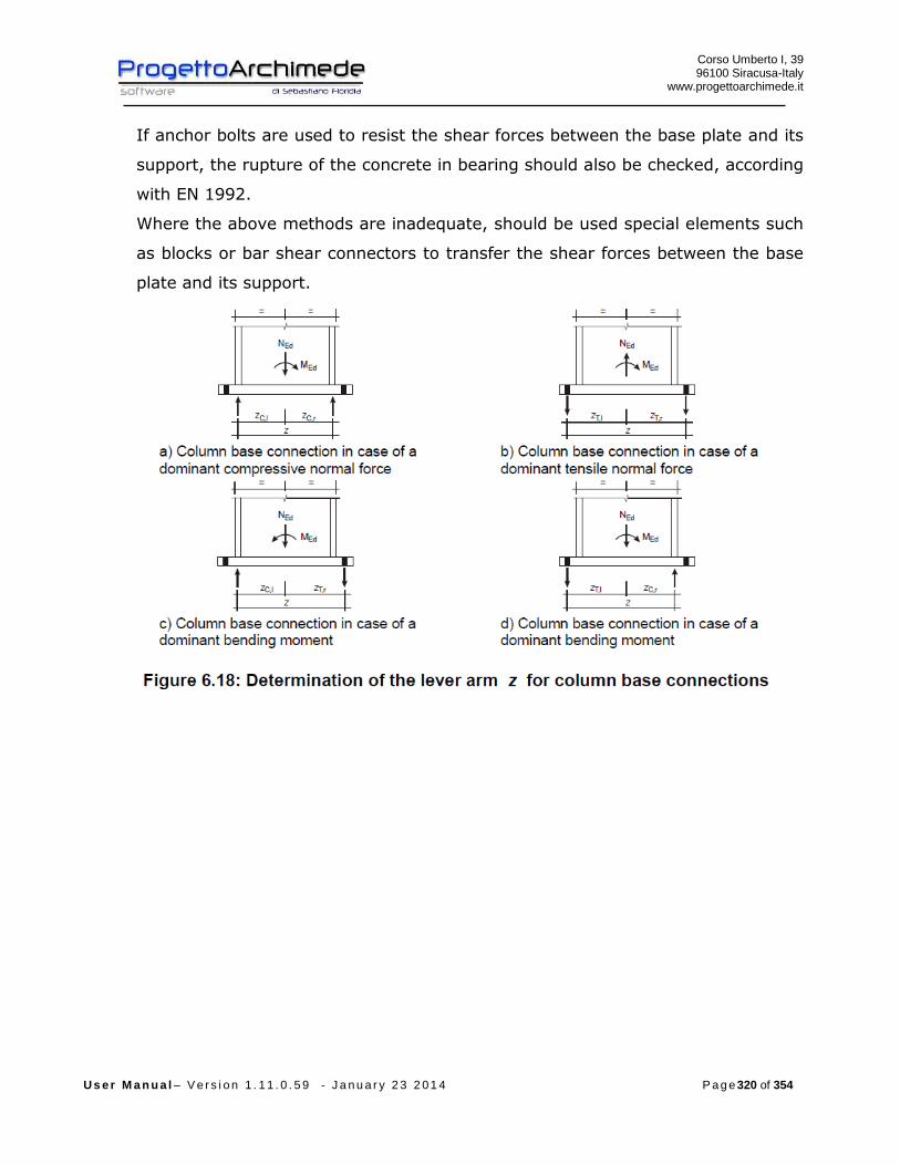
Corso Umberto I, 39 96100 Siracusa-Italy
www.progettoarchimede.it
U s e r M a n u a l – V e r s i o n 1 . 1 1 . 0 . 5 9 - J a n u a r y 2 3 2 0 1 4 P a g e 320 of 354
If anchor bolts are used to resist the shear forces between the base plate and its
support, the rupture of the concrete in bearing should also be checked, according
with EN 1992.
Where the above methods are inadequate, should be used special elements such
as blocks or bar shear connectors to transfer the shear forces between the base
plate and its support.
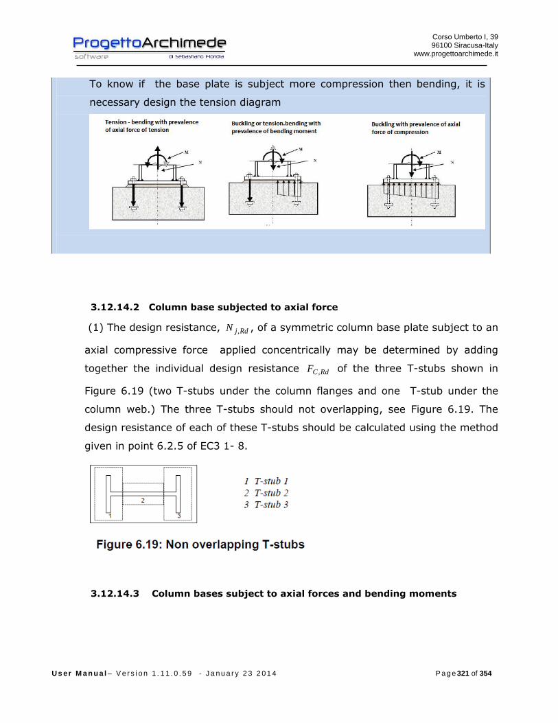
Corso Umberto I, 39 96100 Siracusa-Italy
www.progettoarchimede.it
U s e r M a n u a l – V e r s i o n 1 . 1 1 . 0 . 5 9 - J a n u a r y 2 3 2 0 1 4 P a g e 321 of 354
To know if the base plate is subject more compression then bending, it is
necessary design the tension diagram
3.12.14.2 Column base subjected to axial force
(1) The design resistance, RdjN , , of a symmetric column base plate subject to an
axial compressive force applied concentrically may be determined by adding
together the individual design resistance RdCF , of the three T-stubs shown in
Figure 6.19 (two T-stubs under the column flanges and one T-stub under the
column web.) The three T-stubs should not overlapping, see Figure 6.19. The
design resistance of each of these T-stubs should be calculated using the method
given in point 6.2.5 of EC3 1- 8.
3.12.14.3 Column bases subject to axial forces and bending moments

Corso Umberto I, 39 96100 Siracusa-Italy
www.progettoarchimede.it
U s e r M a n u a l – V e r s i o n 1 . 1 1 . 0 . 5 9 - J a n u a r y 2 3 2 0 1 4 P a g e 322 of 354
(1) The design moment resistance RdjM , of a column base subject to combined
axial force and moment should be determined using the method given in table
6.7, where the contribution of the concrete portion just under the column web
(T-stub 2 di Figure 6.19) to the compressive capacity is omitted.
The following parameters are used in this method:
- RdlTF ,, is the design tension resistance of the left hand side of the joint
- RdrTF ,, is the design tension resistance of the right hand side of the joint
- RdlCF ,, is the design compressive resistance of the left hand side of the joint
- RdrCF ,, is the design compressive resistance of the right hand side of the joint
The design tension resistance RdlTF ,, , of the left side of the joint should be taken
as the smallest values of the design resistance of following basic components:
- the column web in tension under the left column flange RdwctF ,, ;
- the base plate in bending under the left column flange RdpltF ,,
The design tension resistance RdrTF ,, , of the right side of the joint should be
taken as the smallest values of the design resistance of following basic
components:
- the column web in tension under the right column flange RdwctF ,,
- the base plate in bending under the right column flange RdpltF ,,
The design compressive resistance RdlCF ,, of the left side of the joint should be
taken as the smallest values of the design resistance of following basic
component:
- the concrete in compression under the left column flange RdplcF ,, ;
- the left column flange and web in compression RdfccF ,, .
(5) ) The design compressive resistance RdrCF ,, of the right side of the joint
should be taken as the smallest values of the design resistance of following
basic components:
- the concrete in compression under the right column flange RdplcF ,, ;
Corso Umberto I, 39 96100 Siracusa-Italy
www.progettoarchimede.it
U s e r M a n u a l – V e r s i o n 1 . 1 1 . 0 . 5 9 - J a n u a r y 2 3 2 0 1 4 P a g e 323 of 354
- the concrete in compression under the right column flange RdfccF ,, .
For the calculation of lTz , , lCz , , rTz , , rCz , see fig. 6.18.
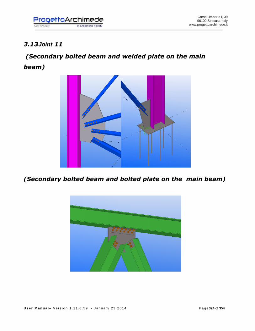
Corso Umberto I, 39 96100 Siracusa-Italy
www.progettoarchimede.it
U s e r M a n u a l – V e r s i o n 1 . 1 1 . 0 . 5 9 - J a n u a r y 2 3 2 0 1 4 P a g e 324 of 354
3.13 Joint 11
(Secondary bolted beam and welded plate on the main
beam)
(Secondary bolted beam and bolted plate on the main beam)
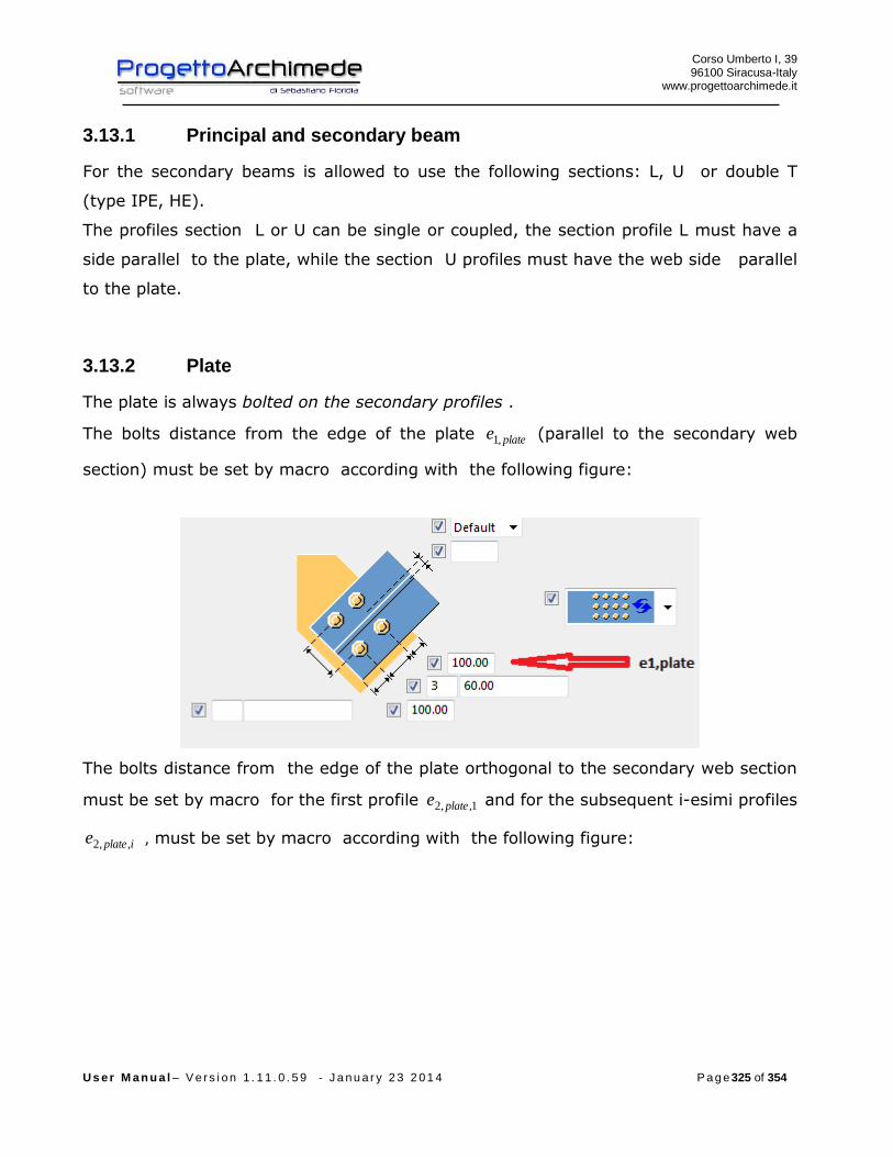
Corso Umberto I, 39 96100 Siracusa-Italy
www.progettoarchimede.it
U s e r M a n u a l – V e r s i o n 1 . 1 1 . 0 . 5 9 - J a n u a r y 2 3 2 0 1 4 P a g e 325 of 354
3.13.1 Principal and secondary beam
For the secondary beams is allowed to use the following sections: L, U or double T
(type IPE, HE).
The profiles section L or U can be single or coupled, the section profile L must have a
side parallel to the plate, while the section U profiles must have the web side parallel
to the plate.
3.13.2 Plate
The plate is always bolted on the secondary profiles .
The bolts distance from the edge of the plate platee ,1 (parallel to the secondary web
section) must be set by macro according with the following figure:
The bolts distance from the edge of the plate orthogonal to the secondary web section
must be set by macro for the first profile 1,,2 platee and for the subsequent i-esimi profiles
iplatee ,,2 , must be set by macro according with the following figure:

Corso Umberto I, 39 96100 Siracusa-Italy
www.progettoarchimede.it
U s e r M a n u a l – V e r s i o n 1 . 1 1 . 0 . 5 9 - J a n u a r y 2 3 2 0 1 4 P a g e 326 of 354
3.13.3 Connections on the principal beam
The plate can be connected to the principal profile according with the following
schemes :
11) Welded plate
10) Welded plate
12) Plate connected with a single angular
7) Plate connected with a double angular
8) Plate connected with a sigle angular
9) 6) Plate connected with a lateral plate
4) Plate connected with a lateral plate
5)
3) Plate connected with a head plate
1) Welded plate
2)

Corso Umberto I, 39 96100 Siracusa-Italy
www.progettoarchimede.it
U s e r M a n u a l – V e r s i o n 1 . 1 1 . 0 . 5 9 - J a n u a r y 2 3 2 0 1 4 P a g e 327 of 354
3.13.3.1 Double T shaped principal beam
If the main beam profile is the type H shape (ex. IPE o HE),the connection with the
plate can be welded or bolted, it is very important to note that the forces transmitted
by the beam on the plate are transmitted only to the main profile, we don’t consider
eventually beams that aren’t in the list of the 11 joint, also if we can see them
graphically in Tekla Structures.
The forces can be transmitted between the plate and the main profile with weld or
with a group of bolts, in succession there is a summary about the type of connections.
Welding joint:
- Connection type 1), 2), 9): the plate is welded to the main profile with two
angular cordons along the contact height between the plate and the main
profile;
- Connection type 6), 7): a plate placed on one of two side of the plate is
connected to the main profile with welding, the force resistant is that of welded
plate and not that of welded plate on the main profile .
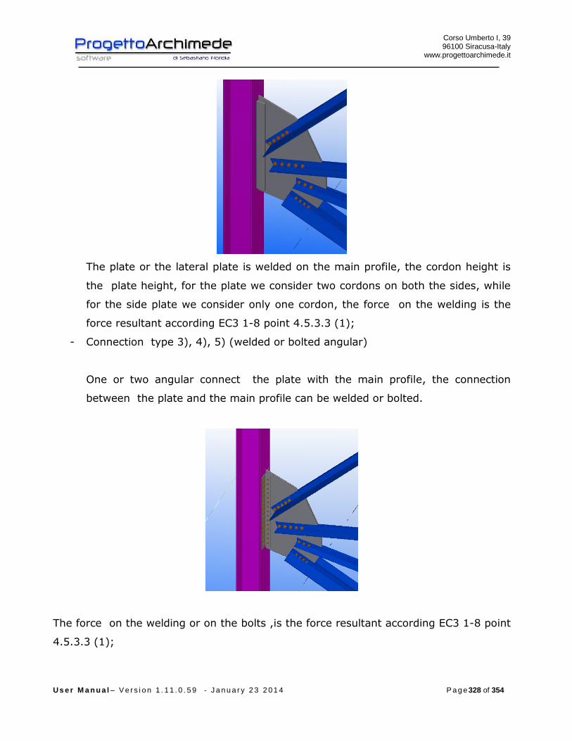
Corso Umberto I, 39 96100 Siracusa-Italy
www.progettoarchimede.it
U s e r M a n u a l – V e r s i o n 1 . 1 1 . 0 . 5 9 - J a n u a r y 2 3 2 0 1 4 P a g e 328 of 354
The plate or the lateral plate is welded on the main profile, the cordon height is
the plate height, for the plate we consider two cordons on both the sides, while
for the side plate we consider only one cordon, the force on the welding is the
force resultant according EC3 1-8 point 4.5.3.3 (1);
- Connection type 3), 4), 5) (welded or bolted angular)
One or two angular connect the plate with the main profile, the connection
between the plate and the main profile can be welded or bolted.
The force on the welding or on the bolts ,is the force resultant according EC3 1-8 point
4.5.3.3 (1);

Corso Umberto I, 39 96100 Siracusa-Italy
www.progettoarchimede.it
U s e r M a n u a l – V e r s i o n 1 . 1 1 . 0 . 5 9 - J a n u a r y 2 3 2 0 1 4 P a g e 329 of 354
- Connection type 8) (head plate welded or bolted)
The plate is welded or bolted to the main profile with a plate.
3.13.4 Actions
On the secondary profile we can apply the following forces:
EdN normal force (positive if tensile)
yEdV , vertical plane shear force
zEdM , bending moment around z axis
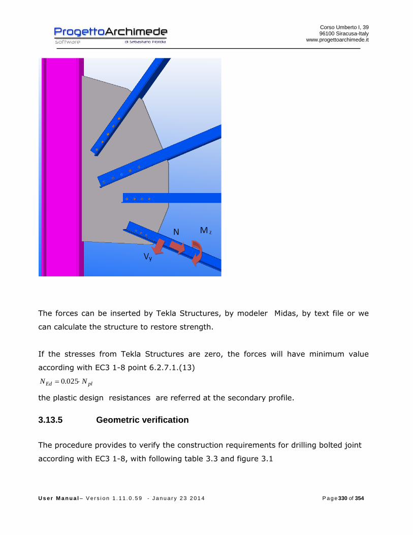
Corso Umberto I, 39 96100 Siracusa-Italy
www.progettoarchimede.it
U s e r M a n u a l – V e r s i o n 1 . 1 1 . 0 . 5 9 - J a n u a r y 2 3 2 0 1 4 P a g e 330 of 354
The forces can be inserted by Tekla Structures, by modeler Midas, by text file or we
can calculate the structure to restore strength.
If the stresses from Tekla Structures are zero, the forces will have minimum value
according with EC3 1-8 point 6.2.7.1.(13)
plEd NN 025.0
the plastic design resistances are referred at the secondary profile.
3.13.5 Geometric verification
The procedure provides to verify the construction requirements for drilling bolted joint
according with EC3 1-8, with following table 3.3 and figure 3.1

Corso Umberto I, 39 96100 Siracusa-Italy
www.progettoarchimede.it
U s e r M a n u a l – V e r s i o n 1 . 1 1 . 0 . 5 9 - J a n u a r y 2 3 2 0 1 4 P a g e 331 of 354

Corso Umberto I, 39 96100 Siracusa-Italy
www.progettoarchimede.it
U s e r M a n u a l – V e r s i o n 1 . 1 1 . 0 . 5 9 - J a n u a r y 2 3 2 0 1 4 P a g e 332 of 354
3.13.6 Design resistance of single bolt and single weld
In this section we recall the common criterions for verification of single bolts and single
weld.
Corso Umberto I, 39 96100 Siracusa-Italy
www.progettoarchimede.it
U s e r M a n u a l – V e r s i o n 1 . 1 1 . 0 . 5 9 - J a n u a r y 2 3 2 0 1 4 P a g e 333 of 354
3.13.6.1 Design resistance at bolt’s tension force
Single bolt tension resistance is:
2,
9.0
M
subRdt
AfF
Where
sA is the tensile stressed area
ubf is the last tensile bolt strength
3.13.6.2 Bolt shear force resistance design
For a shear connection (see class A EC3 1-8 point 3.4.1) the single bolt shear force
design (for only one resistant section) is:
2
,,M
ubvRdv
AfF
If the shear force plane is through the threated bolt portion:
- for classes 4.6, 5.6 e 8.8
6.0v
- for classes 4.8, 5.8 e 10.9
5.0v
If the shear force plane is through not threaded bolt portion:
6.0v
while
A is bolt area
ubf is the last bolt tension
3.13.6.3 Welding design resistance
Fillet weld design resistance is:
lafF dvwRdw .,
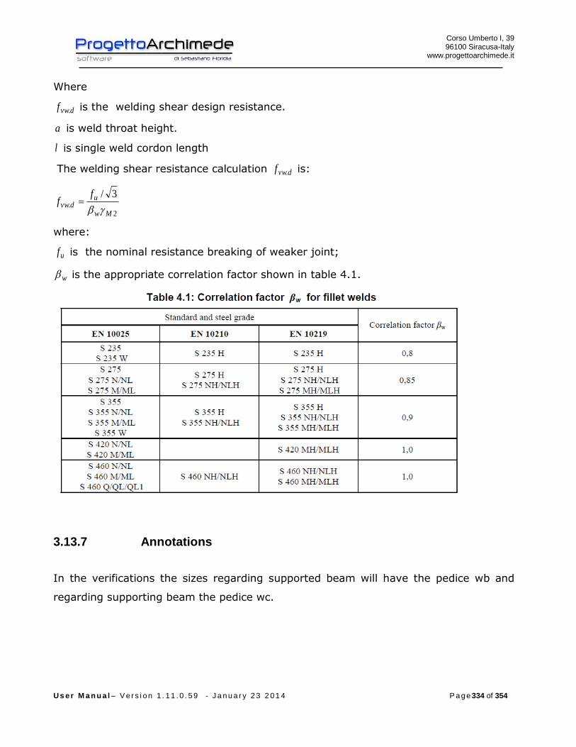
Corso Umberto I, 39 96100 Siracusa-Italy
www.progettoarchimede.it
U s e r M a n u a l – V e r s i o n 1 . 1 1 . 0 . 5 9 - J a n u a r y 2 3 2 0 1 4 P a g e 334 of 354
Where
dvwf . is the welding shear design resistance.
a is weld throat height.
l is single weld cordon length
The welding shear resistance calculation dvwf . is:
2.
3/
Mw
udvw
ff
where:
uf is the nominal resistance breaking of weaker joint;
w is the appropriate correlation factor shown in table 4.1.
3.13.7 Annotations
In the verifications the sizes regarding supported beam will have the pedice wb and
regarding supporting beam the pedice wc.

Corso Umberto I, 39 96100 Siracusa-Italy
www.progettoarchimede.it
U s e r M a n u a l – V e r s i o n 1 . 1 1 . 0 . 5 9 - J a n u a r y 2 3 2 0 1 4 P a g e 335 of 354
3.13.8 Verifications made
The Verifications made on the joint are the following:
- Shear bolt on the supported beam
RdvEdv FF ,,
- Weld on the supporting beam
RdwEdw FF ,,
- Shear and tension force bolt on the supporting beam
trazionee tagliodi presenzaIn 4.1//
trazionesola di presenzaIn
tagliosolo di presenzaIn
,,,,
,,
,,
RdtEdtRdvEdv
RdtEdt
RdvEdv
FFFF
FF
FF
- Net and gross sections verification of profile and plates on the supported and
supporting beam, due to stress tensile and shear force
Rdu
RdplEd N
NN
,
,
Rdu
RdplEd V
VV
,
,
- BlockTearing verification profiles and plates on the supported and supporting
beam, due to tensile and shear force
effEd NN
effEd VV
- Bearing resistance verification on two directions, horizontal and vertical of
profiles and plate on supported beam
RdbEdb FF ,,
Corso Umberto I, 39 96100 Siracusa-Italy
www.progettoarchimede.it
U s e r M a n u a l – V e r s i o n 1 . 1 1 . 0 . 5 9 - J a n u a r y 2 3 2 0 1 4 P a g e 336 of 354
3.13.9 Shear force bolt verification (supported beam)
Verification is done considering together perpendicular force and shear acting on the
supported beam.
If we consider a reference system x-y on supported beam plan, with x coincident with
beam axis, y orthogonal beam axis and the origin in the bolt’ s barycenter, for
equilibrium to vertical translation and rotation relative to supporting web beam axis,
force solicitations in the barycenter of the group of bolts on single bracket are
xyyxEd
yEdy
Edx
eVeVT
VV
NV
,
Where
- ye is the distance between the barycenter of the group of bolts and supported web
axis;
- xe is the distance between the barycenter of the group of bolts and the plate
connection with principal beam;
- EdT is the parasite torsion had to eccentricity.
if the principal beam torsional stiffness isn’t negligible, the connection is assumed as a
constraint joint and zEdxyyxEd MeVeVT , .
The shear forces on the single bolt for single bolt shear plan are:
ibv
EdEdEdy
ibv
EdEdEdx
bv
yyEdy
bv
xxEdx
xJn
TTV
yJn
TTV
nn
VVV
nn
VVV
)(
)(
)(
)(
,
,
,
,
With

Corso Umberto I, 39 96100 Siracusa-Italy
www.progettoarchimede.it
U s e r M a n u a l – V e r s i o n 1 . 1 1 . 0 . 5 9 - J a n u a r y 2 3 2 0 1 4 P a g e 337 of 354
)( 22 ynxnJ bh
i
bvb bolts polar moment
bn bolts total number
vn bolt sections number shear resistant
bhn bolts number per horizontal row
bvn bolts number per vertical row
ix single bolt distance from barycenter of group bolts, in verification we consider maxx
iy single bolt distance from barycenter of group bolts, in verification we consider maxy
The forces resultant on single bolt for single bolt shear plan is:
2,,
2,,, ))()(())()(( EdEdyyEdyEdEdxxEdxEdv TVVVTVVVF
must satisfy
RdvEdv FF ,,
3.13.10 Shear and tension force bolt verification (supporting beam)
The verification is made considering together normal stress, bending and shear force
acting on supported beam.
If we consider a reference system x-y on supporting beam’s plan, with axis x
coincident with beam’s axis, axis y orthogonal to beam’s axis and origin in the bolt’ s
barycenter that are on one angular, for vertical translation and rotation equilibrium
relative to the supported beam axis, the shear force solicitations in the barycentre of
group bolt’s group on single bracket are:
eVT
VV
VV
yEd
yEdy
xEdx
2/
2/
,
,

Corso Umberto I, 39 96100 Siracusa-Italy
www.progettoarchimede.it
U s e r M a n u a l – V e r s i o n 1 . 1 1 . 0 . 5 9 - J a n u a r y 2 3 2 0 1 4 P a g e 338 of 354
If on supporting beam there is only one angular the stresses on the group bolts’
barycenter on bracket are:
eVT
VV
VV
yEd
yEdy
xEdx
,
,
where
e is the distance between the group bolts’ barycenter of single angular and supported
beam’s axis, while EdT is the parasite torsion had to eccentricity.
The shear forces on the single bolt for single bolt shear plan are:
ibv
EdEdEdy
ibv
EdEdEdx
bv
yyEdy
bv
xxEdx
xJn
TTV
yJn
TTV
nn
VVV
nn
VVV
)(
)(
)(
)(
,
,
,
,
With
)( 22 ynxnJ bh
i
bvb bolts polar moment
bn bolts total number
vn bolt sections number shear resistant
bhn bolts number per horizontal row
bvn bolts number per vertical row
ix single bolt distance from barycenter of group bolts, in verification we consider maxx
iy single bolt distance from barycenter of group bolts, in verification we consider maxy
The forces resultant on single bolt for single bolt shear plan is:
2,,
2,,, ))()(())()(( EdEdyyEdyEdEdxxEdxEdv TVVVTVVVF

Corso Umberto I, 39 96100 Siracusa-Italy
www.progettoarchimede.it
U s e r M a n u a l – V e r s i o n 1 . 1 1 . 0 . 5 9 - J a n u a r y 2 3 2 0 1 4 P a g e 339 of 354
The tension force on single bolt belonging to the group of bolts of a bracket is:
bEdt nNF /,
If the torsional stiffness of the principal beam isn’t negligible the bolts for the bending
force resulting from supported beam is tensile stressed and the tensile force on single
bolt belonging to the group of bolts of a side of plate is:
:
ib
xEdbi
i
bh
xEdbEdt y
I
MnNy
yn
MnNF
,
2
,, //
bn bolts total number
bhn bolts total number for horizontal row
iy distance of single bolts row from compression center (the compression center coincides with
the lower edge of the bracket), in the verifications we consider the maxy .
must satisfy :
trazionee tagliodi presenzaIn 4.1//
trazionesola di presenzaIn
tagliosolo di presenzaIn
,,,,
,,
,,
RdtEdtRdvEdv
RdtEdt
RdvEdv
FFFF
FF
FF
3.13.11 Weld verification (supporting beam)
The verification is made considering together normal stress, bending and shear force
acting in the two directions vertical and horizontal on supporting beam.
If we consider a reference system x-y on supporting beam’s plan, with axis x
coincident with beam’s axis, axis y orthogonal to beam’s axis and origin in the vertical
cordon barycenter, for vertical translation and rotation equilibrium relative to the
supporting beam axis, must be there for each angular two horizontal cordon (one
superior and one inferior) and one vertical cordon ,on the supporting beam.
Corso Umberto I, 39 96100 Siracusa-Italy
www.progettoarchimede.it
U s e r M a n u a l – V e r s i o n 1 . 1 1 . 0 . 5 9 - J a n u a r y 2 3 2 0 1 4 P a g e 340 of 354
The stresses on single bracket are:
eVT
MM
VV
VV
NN
yEd
xEdx
yEdy
xEdx
Edz
2/
2/
2/
2/
,
,
,
,
If on supporting beam there is only one angular the stresses on the bracket are:
eVT
MM
VV
VV
NN
yEd
xEdx
yEdy
xEdx
Edz
,
,
,
,
Where
e is the distance between vertical welding barycenter and supporting beam axis, while
EdT is the parasite torsion had to eccentricity.
The horizontal and vertical actions on single weld are:
With
hanglesh angular height
Force resultant on horizontal welding is :
)()()(( 2,,,, NNTVVVF EdEdEdxxEdxEdxw
Force resultant on vertical welding is:
)(
)(2
)(
2/)(
,
,
,
hangles
EdEdEdx
yyEdy
xxEdx
hangles
xEd
h
TTV
VVV
VVV
h
MNNN

Corso Umberto I, 39 96100 Siracusa-Italy
www.progettoarchimede.it
U s e r M a n u a l – V e r s i o n 1 . 1 1 . 0 . 5 9 - J a n u a r y 2 3 2 0 1 4 P a g e 341 of 354
)(,,, yEdyEdyw VVF
must satisfy :
RdwEdw FF ,,
With
lafF dvwRdw ., one angular
2., lafF dvwRdw two angular
Where
l is single cordon length
a is throat height cordon.
3.13.12 Net and gross sections verification (supported beam)
The verification is made both for normal tension forces and shear forces.
3.13.12.1 Tension force
The verification made both for the profile and plates should satisfy if:
1,
Rdt
Ed
N
N
Where RdtN , is the design resistance force at tension force of section cross , equal to
lower of:
m) Plastic design resistance of gross section
0,
M
y
Rdpl
AfN
n) Ultimate design resistance of net section in holes for devices connection
2, 9.0
M
ynet
Rdu
fAN
Corso Umberto I, 39 96100 Siracusa-Italy
www.progettoarchimede.it
U s e r M a n u a l – V e r s i o n 1 . 1 1 . 0 . 5 9 - J a n u a r y 2 3 2 0 1 4 P a g e 342 of 354
The beam resistant side is the web beam, with height like that of angular height
according European code.
The angular resistant side is the sum of two angular cross area if there are both,
that is only one angular.
3.13.12.2 Shear force
The verification is made both for profile and plates should verify:
1,
Rdc
Ed
V
V
Where RdcV , is the shear design resistance force of cross section, equal to lower of:
l) Plastic design resistance of gross section
0,
)3/(
M
y
Rdpl
fAV
m) Ultimate resistance design section of net section in hole for connection
devices
2,
)3/(
M
unetRdu
fAV
The axis is the profile resistant part eventually fillet.
The angular resistant part is the sum of single cross area of two angular if there
are both, or only one angular.
3.13.13 Net and gross sections verification (supporting beam)
The verification is made both for normal tension forces and shear forces.
3.13.13.1 Tension force
The verification made both for the profile and plates should satisfy if:
Corso Umberto I, 39 96100 Siracusa-Italy
www.progettoarchimede.it
U s e r M a n u a l – V e r s i o n 1 . 1 1 . 0 . 5 9 - J a n u a r y 2 3 2 0 1 4 P a g e 343 of 354
1,
Rdt
Ed
N
N
Where RdtN , is the design resistance force at tension force of section cross , equal to
lower of:
a) Plastic design resistance of gross section
0,
M
y
Rdpl
AfN
b)Ultimate design resistance of net section in holes for devices connection
2, 9.0
M
ynet
Rdu
fAN
The tensile force is equal to horizontal shear force acting on supporting beam.
The axis is the profile resistant part, with height equal to angular height in
according with EC3.
The verification is made for single side angular.
3.13.13.2 Shear force
The verification is made both for profile and angular should verify:
1,
Rdc
Ed
V
V
Where RdcV , is the shear design resistance force of cross section, equal to lower of:
a) Plastic design resistance of gross section
0,
)3/(
M
y
Rdpl
fAV
b) Ultimate resistance design section of net section in hole for connection
devices
2,
)3/(
M
unetRdu
fAV
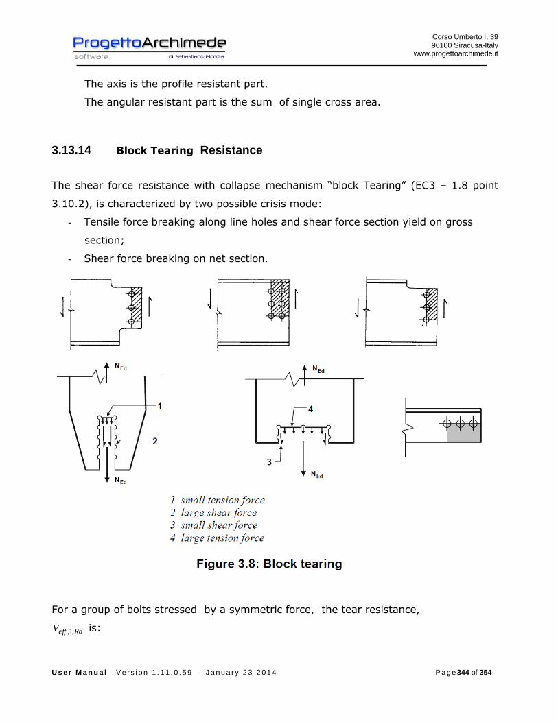
Corso Umberto I, 39 96100 Siracusa-Italy
www.progettoarchimede.it
U s e r M a n u a l – V e r s i o n 1 . 1 1 . 0 . 5 9 - J a n u a r y 2 3 2 0 1 4 P a g e 344 of 354
The axis is the profile resistant part.
The angular resistant part is the sum of single cross area.
3.13.14 Block Tearing Resistance
The shear force resistance with collapse mechanism “block Tearing” (EC3 – 1.8 point
3.10.2), is characterized by two possible crisis mode:
- Tensile force breaking along line holes and shear force section yield on gross
section;
- Shear force breaking on net section.
For a group of bolts stressed by a symmetric force, the tear resistance,
RdeffV ,1, is:

Corso Umberto I, 39 96100 Siracusa-Italy
www.progettoarchimede.it
U s e r M a n u a l – V e r s i o n 1 . 1 1 . 0 . 5 9 - J a n u a r y 2 3 2 0 1 4 P a g e 345 of 354
02
,1,
3
M
nvy
M
ntuRdeff
AfAfV
where:
ntA is net area with tensile force;
nvA is net area with shear force.
For a group of bolts stressed by an eccentric shear force, RdeffV ,2, is given by:
02
,2,
35.0
M
nvy
M
ntuRdeff
AfAfV
The verification is made separately both for perpendicular action and shear force
action, both for profile and angular.
Must be:
effEd NN
effEd VV
3.13.15 Single bolt bearing resistance force
The bearing verification for single bolt resistance section is:
2
1,,
M
ubRdb
dtfkF
Where b is
For external bolts
)1;3
;min(0
1
d
e
f
f
u
ubb
For inner bolts is
)1;4
1
3;min(
0
1 d
p
f
f
u
ubb
While 1k is
for external bolts
)5.2;7.18.2min(0
21
d
ek
Corso Umberto I, 39 96100 Siracusa-Italy
www.progettoarchimede.it
U s e r M a n u a l – V e r s i o n 1 . 1 1 . 0 . 5 9 - J a n u a r y 2 3 2 0 1 4 P a g e 346 of 354
For internal bolts
)5.2;7.14.1min(0
21
d
pk
Where
uf is the ultimate tensile strength of lower resistant plate
ubf is the bolt ultimate tensile strength
t is minimum thickness of plates connection
0d is hole diameter
For the other sizes definition see figure 3.1

Corso Umberto I, 39 96100 Siracusa-Italy
www.progettoarchimede.it
U s e r M a n u a l – V e r s i o n 1 . 1 1 . 0 . 5 9 - J a n u a r y 2 3 2 0 1 4 P a g e 347 of 354
The bearing verification is made separately on two horizontal and vertical directions
both profile and angular of supported and supporting beam. In the verification vertical
and horizontal shear forces acting on local reference system, are combined.
Must be:
RdbEdb FF ,,

Corso Umberto I, 39 96100 Siracusa-Italy
www.progettoarchimede.it
U s e r M a n u a l – V e r s i o n 1 . 1 1 . 0 . 5 9 - J a n u a r y 2 3 2 0 1 4 P a g e 348 of 354
Index
1 INTRODUCTION 2
1.1 All you necessarily need know before starting 2 2 DIRECTIONS 2
2.1 Characteristics of the Software 2 2.2 Minimum qualification hardware and software 2 2.3 Conventions 3 2.4 Activation License 3 2.5 Off License 4 2.6 Start up Application 4 2.7 Software’s Language 4 2.8 Software ‘s interface graphic 4 2.9 Stress made by Midas: 8 3 CONNECTIONS – THEORY AND METHOD 9
3.1 Joint 141 (Supporting beam – Supported beam) 9 3.1.1 Angles 10
3.1.2 Forces 11
3.1.3 Geometric verification 12
3.1.4 Design resistance of single bolt and single weld 13
3.1.5 Annotations 15
3.1.6 Verifications made 15
3.1.7 Shear force bolt verification (supported beam) 17
3.1.8 Weld verification (supported beam) 18
3.1.9 Shear and tension force bolt verification (supporting beam) 19
3.1.10 Weld verification (supporting beam) 21
3.1.11 Verification of net and gross sections (supported beam) 23
3.1.12 Verification net and gross section (supporting beam) 24
3.1.13 Resistance design for Block Tearing 25
3.1.14 Single bolt bearing resistance force 27
3.2 Joint 142 (Supporting beam – Supported beam) 29 3.2.1 Plates 30
3.2.2 Actions 30

Corso Umberto I, 39 96100 Siracusa-Italy
www.progettoarchimede.it
U s e r M a n u a l – V e r s i o n 1 . 1 1 . 0 . 5 9 - J a n u a r y 2 3 2 0 1 4 P a g e 349 of 354
3.2.3 Geometric verification 32
3.2.4 Net and gross sections verification (supported beam) 40
3.2.5 Resistance for Block Tearing 41
3.2.6 Single bolt bearing resistance force 44
3.3 Joint 143 (Supporting beam – Supported beam) 46 3.3.1 Angles 47
3.3.2 Forces 48
3.3.3 Geometric verification 49
3.3.4 Design resistance of single bolt and single weld 51
3.3.5 Annotations 53
3.3.6 Verifications made 54
3.3.7 Shear bolt verification (supported beam) 55
3.3.8 Verification of the Welding (supported beam) 56
3.3.9 Shear and tensile force verification (supporting beam) 58
3.3.10 Verification of the weld (supporting beam) 60
3.3.11 Verification net and gross sections (supported beam) 62
3.3.12 Verification net and gross section (supporting beam) 63
3.3.13 Resistance for Block Tearing 64
3.3.14 Single bolt bearing resistance force 66
3.4 Joint 144 - (Supporting beam – Supported beam) 68 3.4.1 Plates 69
3.4.2 Forces 69
3.4.3 Geometric verification 70
3.4.4 Design resistance of single bolt and single weld 72
3.4.5 Annotations 74
3.4.6 Verifications made 75
3.4.7 Weld verification (supported beam) 75
3.4.8 Shear and tension force bolt verification (supporting beam) 77
3.4.9 Net and gross sections verification (supported beam) 79
3.4.10 Resistance for Block Tearing 80
3.4.11 Single bolt bearing resistance force 82
Corso Umberto I, 39 96100 Siracusa-Italy
www.progettoarchimede.it
U s e r M a n u a l – V e r s i o n 1 . 1 1 . 0 . 5 9 - J a n u a r y 2 3 2 0 1 4 P a g e 350 of 354
3.5 Joint 42 (Beam –Web beam) 84 3.5.1 Forces 84
3.5.1 Geometric verification 85
3.5.2 Design resistance of single bolt 88
3.5.3 Annotations 89
3.5.4 Verification made 89
3.5.5 Flange design resistance due to axial and bending force 89
3.5.6 Joint design resistance due to the shear force on the web 90
3.5.7 Verification of Net and gross sections 91
3.6 Jonts 77 (Beam – Web beam) 94 3.6.1 Forces 94
3.6.2 Geometric verification 96
3.6.3 Design resistance of single bolt 98
3.6.4 Annotations 99
3.6.5 Verifications made 99
3.6.6 Flange design resistance due to axial and bending force 99
3.6.7 Joint design resistance due to the shear force on the web 100
3.6.8 Verification of Net and gross sections 101
3.7 Joint 14 (Beam – Flange bolted beam) 103 3.7.1 Stiffeners on the beam 104
3.7.2 Forces 104
3.7.3 Geometric verification 106
3.7.4 Design resistance of single bolt and single weld 107
3.7.5 Verifications made 109
3.7.6 Single bolt bearing resistance 110
3.7.7 Plate Connection in bending 112
3.7.8 Plate and web beam in compression 116
3.7.9 Beam web in tension 119
3.7.10 Welding 120
3.7.11 Joint design resistance due to axial force 121
3.7.12 Shear resistance 122

Corso Umberto I, 39 96100 Siracusa-Italy
www.progettoarchimede.it
U s e r M a n u a l – V e r s i o n 1 . 1 1 . 0 . 5 9 - J a n u a r y 2 3 2 0 1 4 P a g e 351 of 354
3.7.13 Bending force resistance 124
3.7.14 Resistance to buckling and tension-bending 128
3.8 Joint 124 (Connection beam – circular section beam) 129 3.8.1 Forces 129
3.8.2 Geometric verification 131
3.8.3 Design resistance of single bolt and single weld 132
3.8.4 Verifications made 135
3.8.5 Bearing resistance of single bolt 136
3.8.6 Plate Connection in bending 138
3.8.7 Plate and web beam in compression 143
3.8.8 Beam web in tension 145
3.8.9 Welding 146
3.8.10 Joint design resistance due to axial force 147
3.8.11 Shear resistance 148
3.8.12 Bending force resistance 150
3.8.13 Resistance to buckling and tension-bending 154
3.9 Joint 128 (Beam web – Column plate welded) 155 3.9.1 Stiffeners of the column 156
3.9.2 Forces 156
3.9.3 Design resistance of single bolt and single weld 157
3.9.4 Verifications made 159
3.9.5 Design resistance of column web panel in shear 161
3.9.6 Resistance of column web in transverse compression 167
3.9.7 Resistance of web Column in transverse tension 174
3.9.8 Resistance of column flange in transverse bending 178
3.9.9 Plate and web beam in compression 179
3.9.10 Weldings 183
3.9.11 Joint design resistance due to axial force 187
3.9.12 Shear resistance 187
3.9.13 Resistance to bending force 188
3.9.14 Resistance to buckling and tension-bending 191

Corso Umberto I, 39 96100 Siracusa-Italy
www.progettoarchimede.it
U s e r M a n u a l – V e r s i o n 1 . 1 1 . 0 . 5 9 - J a n u a r y 2 3 2 0 1 4 P a g e 352 of 354
3.10 Joint 40 (Beam – plate column bolted, reinforced) 192 3.10.1 Stiffeners on the column 193
3.10.2 Stiffeners on the beam 194
3.10.3 Forces 195
3.10.4 Geometric verification 195
3.10.5 Design resistance of single bolt and single weld 197
3.10.6 Verifications made 200
3.10.7 Design resistance of column web panel in shear 201
3.10.8 Resistance of column web in transverse compression 208
3.10.9 Single bolt bearing resistance 215
3.10.10 Resistance of web Column in transverse tension 218
3.10.11 Resistance of column flange in transverse bending 222
3.10.12 Plate Connection in bending 229
3.10.13 Plate and web beam in compression 235
3.10.14 Beam web in tension 238
3.10.15 Weldings 238
3.10.16 Joint design resistance due to axial force 242
3.10.17 Shear resistance 243
3.10.18 Bending force Resistance 245
3.10.19 Resistance to buckling and tension-bending 249
3.11 Connection 1014 (rectangular base plate connection) 250 3.11.1 Stiffeners 251
3.11.2 Shear Key 251
3.11.3 Anchor steel bars 252
3.11.4 Forces 253
3.11.5 Geometrical verification 254
3.11.6 Design resistance of single bolt and single weld 255
3.11.7 Verifications made 258
1.1.8 Verification of shear force 259
3.11.8 Resistance to bearing of single bolt 263
3.11.9 Base plate in compression 265
Corso Umberto I, 39 96100 Siracusa-Italy
www.progettoarchimede.it
U s e r M a n u a l – V e r s i o n 1 . 1 1 . 0 . 5 9 - J a n u a r y 2 3 2 0 1 4 P a g e 353 of 354
3.11.10 Base plate in bending under tension 269
3.11.11 Column flange and web in compression 274
3.11.12 Tension of beam web 276
3.11.13 Tension of anchor bolts 276
3.11.14 Design resistance of column bases with base plates 283
3.12 Joint 1052 (connection circular base plate) 288 3.12.1 Stiffeners 289
3.12.2 Anchor bolts 289
3.12.3 Forces 290
3.12.4 Geometrical verification 291
3.12.5 Design resistance of single bolt and single weld 293
3.12.6 Verifications made 296
3.12.7 Verification of shear force 297
3.12.8 Bearing resistance for the single bolt 298
3.12.9 Base in compression 301
3.12.10 Connection base plate in bending 305
3.12.11 Section of column in compression 309
3.12.12 Column section in tension 311
3.12.13 Anchor bolt in tension 312
3.12.14 Design resistance of column bases with base plates 319
3.13 Joint 11 324 (Secondary bolted beam and welded plate on the main beam) 324 (Secondary bolted beam and bolted plate on the main beam) 324
3.13.1 Principal and secondary beam 325
3.13.2 Plate 325
3.13.3 Connections on the principal beam 326
The plate can be connected to the principal profile according with the following
schemes : 326
3.13.4 Actions 329
3.13.5 Geometric verification 330
3.13.6 Design resistance of single bolt and single weld 332
3.13.7 Annotations 334
Corso Umberto I, 39 96100 Siracusa-Italy
www.progettoarchimede.it
U s e r M a n u a l – V e r s i o n 1 . 1 1 . 0 . 5 9 - J a n u a r y 2 3 2 0 1 4 P a g e 354 of 354
3.13.8 Verifications made 335
3.13.9 Shear force bolt verification (supported beam) 336
3.13.10 Shear and tension force bolt verification (supporting beam) 337
3.13.11 Weld verification (supporting beam) 339
3.13.12 Net and gross sections verification (supported beam) 341
3.13.13 Net and gross sections verification (supporting beam) 342
3.13.14 Block Tearing Resistance 344
3.13.15 Single bolt bearing resistance force 345