infrastruxure 80kw - schneider-electric.com · password-protected screens ... see the documentation...
TRANSCRIPT
InfraStruXure
80kW
Symmetra PX UPSXR Battery Enclosure
PDU with System BypassRemote Distribution Panel
Operation andMaintenance Manual
208/480/600V


Contents
Safety .....................................................................3
Warnings . . . . . . . . . . . . . . . . . . . . . . . . . . . . . . . . . . . . . . . . . 3Safety symbols used in this guide . . . . . . . . . . . . . . . . . . . . . . . 3
Installation/Maintenance . . . . . . . . . . . . . . . . . . . . . . . . . . . . . . 3
Maintenance performed while the PDU is receiving input power . . . . . . . . . . . . . . . . . . . . . . . . . . . . . . 4
Total Power Off . . . . . . . . . . . . . . . . . . . . . . . . . . . . . . . . . . . . . 4
DANGER—Risk of Electric Shock! . . . . . . . . . . . . . . . . . . . . . . . . 5
Batteries—CAUTION. . . . . . . . . . . . . . . . . . . . . . . . . . . . . . . . . . 5
Class A ITE . . . . . . . . . . . . . . . . . . . . . . . . . . . . . . . . . . . . . . . . . 5
InfraStruXure System ............................................... 7
Operation . . . . . . . . . . . . . . . . . . . . . . . . . . . . . . . . . . . . . . . . . 7How to transfer the UPS into maintenance bypass operation . . . 7
How to return from maintenance bypass operation . . . . . . . . . 10
How to ensure Total Power Off . . . . . . . . . . . . . . . . . . . . . . . . 13
How to apply power to the system. . . . . . . . . . . . . . . . . . . . . . 15
Symmetra PX UPS (80kW)...................................... 19
Overview . . . . . . . . . . . . . . . . . . . . . . . . . . . . . . . . . . . . . . . . 19Front view . . . . . . . . . . . . . . . . . . . . . . . . . . . . . . . . . . . . . . . 19
Front view (interior) . . . . . . . . . . . . . . . . . . . . . . . . . . . . . . . . . 20
Front view (lower interior) . . . . . . . . . . . . . . . . . . . . . . . . . . . 21
InfraStruXure Operation and Maintenance Manual i

Operation. . . . . . . . . . . . . . . . . . . . . . . . . . . . . . . . . . . . . . . . 22Display interface . . . . . . . . . . . . . . . . . . . . . . . . . . . . . . . . . . . 22
Navigating screens. . . . . . . . . . . . . . . . . . . . . . . . . . . . . . . . . . 23
Top-Level Status Screen . . . . . . . . . . . . . . . . . . . . . . . . . . . . . . 24
Top-Level Menu Screen . . . . . . . . . . . . . . . . . . . . . . . . . . . . . . 24
Control screen . . . . . . . . . . . . . . . . . . . . . . . . . . . . . . . . . . . . . 25
Status screens . . . . . . . . . . . . . . . . . . . . . . . . . . . . . . . . . . . . . 25
Setup screen . . . . . . . . . . . . . . . . . . . . . . . . . . . . . . . . . . . . . . 27
Accessories screen . . . . . . . . . . . . . . . . . . . . . . . . . . . . . . . . . . 28
Logging screens . . . . . . . . . . . . . . . . . . . . . . . . . . . . . . . . . . . . 28
Display screens . . . . . . . . . . . . . . . . . . . . . . . . . . . . . . . . . . . . 29
Diag screens . . . . . . . . . . . . . . . . . . . . . . . . . . . . . . . . . . . . . . 29
Help screens. . . . . . . . . . . . . . . . . . . . . . . . . . . . . . . . . . . . . . . 29
Troubleshooting . . . . . . . . . . . . . . . . . . . . . . . . . . . . . . . . . . . 30General status . . . . . . . . . . . . . . . . . . . . . . . . . . . . . . . . . . . . . 31
General fault . . . . . . . . . . . . . . . . . . . . . . . . . . . . . . . . . . . . . . 33
Module failure . . . . . . . . . . . . . . . . . . . . . . . . . . . . . . . . . . . . . 34
Threshold alarm . . . . . . . . . . . . . . . . . . . . . . . . . . . . . . . . . . . 34
Bypass . . . . . . . . . . . . . . . . . . . . . . . . . . . . . . . . . . . . . . . . . . . 35
Maintenance . . . . . . . . . . . . . . . . . . . . . . . . . . . . . . . . . . . . . 36Handling and transport . . . . . . . . . . . . . . . . . . . . . . . . . . . . . . 36
Module replacement . . . . . . . . . . . . . . . . . . . . . . . . . . . . . . . . 36
How to obtain replacement modules . . . . . . . . . . . . . . . . . . . . 37
How to replace a power module . . . . . . . . . . . . . . . . . . . . . . . 38
How to replace an intelligence module. . . . . . . . . . . . . . . . . . . 40
How to replace cards . . . . . . . . . . . . . . . . . . . . . . . . . . . . . . . . 41
Replacement parts . . . . . . . . . . . . . . . . . . . . . . . . . . . . . . . . . . 41
How to return modules to APC. . . . . . . . . . . . . . . . . . . . . . . . . 42
Specifications . . . . . . . . . . . . . . . . . . . . . . . . . . . . . . . . . . . . . 43
XR Battery Enclosure ............................................ 45
Overview . . . . . . . . . . . . . . . . . . . . . . . . . . . . . . . . . . . . . . . . 45Front view (interior) . . . . . . . . . . . . . . . . . . . . . . . . . . . . . . . . . 46
Troubleshooting . . . . . . . . . . . . . . . . . . . . . . . . . . . . . . . . . . . 47
InfraStruXure Operation and Maintenance Manual ii

Maintenance . . . . . . . . . . . . . . . . . . . . . . . . . . . . . . . . . . . . . . 48Replacement parts . . . . . . . . . . . . . . . . . . . . . . . . . . . . . . . . . . 48
How to replace a card . . . . . . . . . . . . . . . . . . . . . . . . . . . . . . . 48
Battery replacement . . . . . . . . . . . . . . . . . . . . . . . . . . . . . . . . . 49
How to obtain replacement batteries . . . . . . . . . . . . . . . . . . . . 50
How to replace a battery unit . . . . . . . . . . . . . . . . . . . . . . . . . 51
Specifications . . . . . . . . . . . . . . . . . . . . . . . . . . . . . . . . . . . . . 52
PDU with System Bypass and RDP ........................ 53
Overview . . . . . . . . . . . . . . . . . . . . . . . . . . . . . . . . . . . . . . . . 53PDU front view (exterior) . . . . . . . . . . . . . . . . . . . . . . . . . . . . . 54
Front view (interior) . . . . . . . . . . . . . . . . . . . . . . . . . . . . . . . . . 55
Front view (door open) . . . . . . . . . . . . . . . . . . . . . . . . . . . . . . 56
Rear view (interior) . . . . . . . . . . . . . . . . . . . . . . . . . . . . . . . . . 57
RDP front view (door open) . . . . . . . . . . . . . . . . . . . . . . . . . . . 58
Operation. . . . . . . . . . . . . . . . . . . . . . . . . . . . . . . . . . . . . . . . 59Display interface . . . . . . . . . . . . . . . . . . . . . . . . . . . . . . . . . . . 59
Top-level status screens . . . . . . . . . . . . . . . . . . . . . . . . . . . . . . 60
Top-level Menu screen . . . . . . . . . . . . . . . . . . . . . . . . . . . . . . . 60
Navigating through screens . . . . . . . . . . . . . . . . . . . . . . . . . . 60
Password-protected screens . . . . . . . . . . . . . . . . . . . . . . . . . . . 61
Load-Meter screen . . . . . . . . . . . . . . . . . . . . . . . . . . . . . . . . . . 62
Volt-Meter screen . . . . . . . . . . . . . . . . . . . . . . . . . . . . . . . . . . 62
Contacts screen . . . . . . . . . . . . . . . . . . . . . . . . . . . . . . . . . . . . 63
Breakers screen . . . . . . . . . . . . . . . . . . . . . . . . . . . . . . . . . . . . 63
Alarms screen. . . . . . . . . . . . . . . . . . . . . . . . . . . . . . . . . . . . . . 64
Panel screen . . . . . . . . . . . . . . . . . . . . . . . . . . . . . . . . . . . . . . 67
Config screen . . . . . . . . . . . . . . . . . . . . . . . . . . . . . . . . . . . . . 69
Customization . . . . . . . . . . . . . . . . . . . . . . . . . . . . . . . . . . . . 72How to connect contacts to the PDU Monitoring Unit . . . . . . . 72
Maintenance . . . . . . . . . . . . . . . . . . . . . . . . . . . . . . . . . . . . . 74Important safety instructions . . . . . . . . . . . . . . . . . . . . . . . . . . 74
How to add a breaker on the PDU or RDP . . . . . . . . . . . . . . . . 74
How to add a power cord to the PDU or RDP . . . . . . . . . . . . . . 75
Specifications . . . . . . . . . . . . . . . . . . . . . . . . . . . . . . . . . . . . . 76
InfraStruXure Operation and Maintenance Manual iii

Product Information ............................................. 79
Warranty . . . . . . . . . . . . . . . . . . . . . . . . . . . . . . . . . . . . . . . . 79InfraStruXure Standard Warranty . . . . . . . . . . . . . . . . . . . . . . 79
Service Packages . . . . . . . . . . . . . . . . . . . . . . . . . . . . . . . . . . . 801-Day On-Site Training Service . . . . . . . . . . . . . . . . . . . . . . . . 80
1-Year on-site service—InfraStruXure Type B . . . . . . . . . . . . . . . 80
Remote Monitoring Service—InfraStruXure Type B . . . . . . . . . . 83
Network integration service —all product lines . . . . . . . . . . . . 83
Preventative Maintenance Visit—InfraStruXure Type B . . . . . . . 85
Start-Up Service—InfraStruXure Type B . . . . . . . . . . . . . . . . . . . 87
Life-Support Policy . . . . . . . . . . . . . . . . . . . . . . . . . . . . . . . . . 89APC Three-Phase Systems . . . . . . . . . . . . . . . . . . . . . . . . . . . . . 89
How to Contact APC . . . . . . . . . . . . . . . . . . . . . . . . . . . . . . . . 90APC Worldwide Customer Support . . . . . . . . . . . . . . . . . . . . . . 90
How to Obtain Service . . . . . . . . . . . . . . . . . . . . . . . . . . . . . . 91Obtaining service . . . . . . . . . . . . . . . . . . . . . . . . . . . . . . . . . . 91
iv InfraStruXure Operation and Maintenance Manual

About this Manual
This manual is intended for end-users of an 80kW InfraStruXure system. It covers the operation and basic maintenance of the following InfraStruXure products:
• Symmetra PX UPS• XR Battery Enclosure• PDU with System Bypass• Remote Distribution Panel
For additional information about these products, see the following manuals that were included with the PDU:
• The InfraStruXure 80kW Installation and Start-Up Manual (990-1467) covers the installation, start-up, and configuration of an entire Type B InfraStruXure power and rack solution.
• The 80kW Utility Connection instruction sheet (990-1469) provides specific instructions for the electrician connecting power to the PDU with System Bypass.
If you also purchased InfraStruXure-certified products that are not listed above, see the documentation included with each product for specific safety, installation, and operation instructions.
Illustrations The illustrations of products in this manual may vary slightly from the products in your InfraStruXure system.
InfraStruXure Operation and Maintenance Manual 1


Safety
Warningsa
Safety symbols used in this guide
SAVE THESE INSTRUCTIONS. This manual contains important instructions that must be followed during installation and maintenance of the InfraStruXure system.
Installation/MaintenanceOnly a certified electrician can:
• connect the PDU with System Bypass to utility power
Only a certified electrician or an APC Field Service Engineer can:• connect the PDU with System Bypass to the Symmetra PX UPS• perform maintenance of the PDU with System Bypass
ElectricalHazard
Indicates a hazard, which, if not avoided, could result in injury or death.
Warning
Indicates a hazard, which, if not avoided, could result in damage to a product or other property.
Note
Indicates important information.
Heavy
Indicates a heavy load that should not be lifted without assistance.
Indicates that more information is available on this subject in a different section of this manual.
See also
Indicates that more information is available on the same subject in a different manual.
InfraStruXure Operation and Maintenance Manual 3

When you connect the PDU with System Bypass to utility power, you must install a circuit breaker to protect the PDU with System Bypass against short-circuit current.
Determine the type of circuit breaker that you need to install:
Maintenance performed while the PDU is receiving input power
APC does not recommend that you perform maintenance of the PDU with System Bypass while it is receiving input power. However, APC is aware that due to the critical nature of data center loads, this may occur. If performing maintenance while the PDU is receiving input power, observe the following precautions to reduce the risk of electric shock:
1. Never work alone.2. Perform the maintenance only if you have a certified electrician
who is trained in the hazards of live electrical installation.3. Know the procedure for disconnecting electricity to the PDU with
System Bypass and the data center in the event of an emergency.4. Wear eye protection and use rubber-insulated gloves and rubber-
insulated boots. If rubber-insulated gloves are not available, work with one hand in your pocket or behind your back to prevent an arm-to-arm electric shock.
5. Use double-insulated tools. If double-insulated tools are not available, insulate all tools with electrical tape.
6. Use electrical tape to insulate uninsulated conductive parts.7. Always follow local and site regulations when working on the
PDU with System Bypass.
Total Power Off 1. Set the Symmetra PX UPS System Enable switch to Off. 2. Set the Symmetra PX UPS DC Disconnect switch to Off.3. Set the PDU with System Bypass Main Input switch to Off. 4. Set the DC Disconnect breaker of each XR Battery Enclosure to
Off.5. Set the utility power circuit breaker to Off.6. Disconnect the batteries in the UPS by pulling them out
approximately 25 mm from their normal position.7. Disconnect the batteries in the XR Battery Enclosure by pulling
them out approximately 25 mm from their normal position.
Input Voltage Circuit Breaker Sizing
208V
480V
600V
4 InfraStruXure Operation and Maintenance Manual

DANGER—Risk of Electric Shock!
Batteries—CAUTION
Class A ITE This is a Class A product, based on the standard of the Voluntary Control Council for Interference by Information Technology Equipment (VCCI). If this equipment is used in a residential environment, radio disturbance may occur, in which case, the user may be required to take corrective actions.
ElectricalHazard
Hazardous, live parts inside the Symmetra PX UPS are energized from the battery supply even when the AC power is disconnected.
Hazardous, live parts may exist inside the PDU with System Bypass because of the Symmetra PX UPS inverter even when the AC power is disconnected. Test any electrical parts before touching them.
ElectricalHazard
Risk of Electrical Shock and Energy Hazard, 96 V, 7.2 Ah battery.
To replace a battery unit, use only the same APC Battery Unit, model SYBTU1.
Before replacing batteries, remove conductive jewelry such as chains, wrist watches and rings. High short-circuit current through conductive materials could cause severe burns.
Do not dispose of batteries in a fire. The batteries may explode.
Do not open or mutilate batteries. Released electrolyte is toxic and harmful to the skin and eyes.
InfraStruXure Operation and Maintenance Manual 5


InfraStruXure System
Operation
How to transfer the UPS into maintenance bypass operation
When servicing the UPS, transfer the UPS into maintenance bypass operation. When the UPS is operating in maintenance bypass, input power flows directly to the PDU and out to the load equipment.
Note
Select Help from the top-level menu screen of the PDU display interface and select the first help topic, Putting the PDU into Maintenance Bypass, or follow the procedure below.
1. Command the UPS into static bypass operation through the UPS display interface:
a. Press the ESC key at the top-level status screen to open the top-level menu.
Top-Level Menu
b. Select Control on the top-level menu and press the ENTER key.
c. Select UPS Into Bypass on the Control menu and press the ENTER key.
Control Menu
d. Confirm the selection on the next screen: select Yes, UPS into Bypass and press the ENTER key.
Confirmation Screen
Control LoggingStatus DisplaySetup DiagsAccessories Help
Do Self TestSimulate Power FailGraceful Reboot
UPS Into Bypass
Graceful Turn OffStart Runtime CalTurn Load On/Off
ConfirmYes, UPS into BypassNo, Abort
InfraStruXure Operation and Maintenance Manual 7

InfraStruXure System—Operation
The BYPASS LED illuminates and the following screens appear:
Note
The H3 LED above the Q3 breaker illuminates, indicating that it is safe to operate the Q3 breaker.
2. Close (turn ON) the Q3 breaker on the PDU with System Bypass.
Note
The H2 LED above the Q2 breaker illuminates, indicating that it is safe to operate the Q2 breaker.
3. Open (turn OFF) the Q2 breaker on the PDU with System Bypass.
UPS has beencommanded to gointo Bypass...
UPS load is in Bypass
Press any key...
8 InfraStruXure Operation and Maintenance Manual

InfraStruXure System—Operation
The UPS is now in maintenance bypass operation.
4. Set the Symmetra PX UPS System Enable switch to the OFF position.
5. Set the XR Battery Enclosure DC Disconnect breaker to the OFF position.
6. Open (turn OFF) the Q1 breaker on the PDU with System Bypass.
InfraStruXure Operation and Maintenance Manual 9

InfraStruXure System—Operation
How to return from maintenance bypass operation
The UPS will show a Forced Bypass message on the display interface and the Fault LED will be red.
Note
Select Help from the top-level menu screen on the PDU display interface and select the second help topic, Returning from PDU Maintenance Bypass, or follow the procedure below:
1. Close (turn ON) the Q1 breaker on the PDU with System Bypass.
2. Set the Symmetra PX UPS System Enable switch to the ON position.
3. Set the XR Battery Enclosure DC Disconnect breaker to ON.
10 InfraStruXure Operation and Maintenance Manual

InfraStruXure System—Operation
4. Command the UPS to apply power to the load:
a. Press the ESC key at the top-level status screen to open the top-level menu and have access to eight submenus.
b. Select Control and press the ENTER key.
Top-Level Menu
a. Select Turn UPS On from the Control menu and press the ENTER key.
Control Menu
b. On the next screen: select Yes, UPS Load ON and press the ENTER key.
Confirmation Screen
The LOAD ON LED illuminates and the interface displays the following two screens:
5. Command the UPS into static bypass operation through the UPS display interface:
a. Press the ESC key at the top-level status screen to open the top-level menu.
Top-Level Menu
b. Select Control on the top-level menu and press the ENTER key.
Control LoggingStatus DisplaySetup DiagsAccessories Help
UPS Into BypassDo Self TestSimulate Power FailGraceful Reboot
Graceful Turn OffStart Runtime CalTurn Load On/Off
ConfirmYes, Turn UPS ONNo, Abort
UPS has beencommanded to turnload power on...
UPS load is on
Press any key...
Control LoggingStatus DisplaySetup DiagsAccessories Help
InfraStruXure Operation and Maintenance Manual 11

InfraStruXure System—Operation
c. Select UPS Into Bypass on the Control menu and press the ENTER key.
Control Menu
d. Confirm the selection on the next screen: select Yes, UPS into Bypass and press the ENTER key.
Confirmation Screen
Note
The H2 LED above the Q2 breaker illuminates indicating that it is safe to operate the Q2 breaker.
6. Close (turn ON) the Q2 breaker on the PDU with System Bypass.
Note
The H3 LED above the Q3 breaker illuminates, indicating that it is safe to operate the Q3 breaker
7. Open (turn OFF) the Q3 breaker on the PDU with System Bypass.
The UPS automatically comes out of Static Bypass.
Do Self TestSimulate Power FailGraceful Reboot
UPS Into Bypass
Graceful Turn OffStart Runtime CalTurn Load On/Off
ConfirmYes, UPS into BypassNo, Abort
12 InfraStruXure Operation and Maintenance Manual

InfraStruXure System—Operation
How to ensure Total Power Off
1. Set the Symmetra PX UPS System Enable switch to the OFF position.
2. Set the XR Battery Enclosure DC Disconnect breaker to the OFF position.
3. Pull out all battery units in the XR Battery Enclosures to the red battery disconnect line.
InfraStruXure Operation and Maintenance Manual 13

InfraStruXure System—Operation
4. Set the Main Input switch on the PDU with System Bypass to the OFF position.
5. Open (turn OFF) the Q1, Q2, and Q3 breakers on the PDU with System Bypass.
6. Set the utility power breaker to the OFF or Locked Out position.
14 InfraStruXure Operation and Maintenance Manual

InfraStruXure System—Operation
How to apply power to the system
1. Set the utility power breaker to ON.
2. Set the Main Input switch on the PDU with System Bypass to ON.
3. Ensure that all battery units in the XR Battery Enclosures are fully pushed and locked into position.
4. Close (turn ON) the Q1 breaker on the PDU with System Bypass to apply power to the UPS.
InfraStruXure Operation and Maintenance Manual 15

InfraStruXure System—Operation
5. Set the UPS System Enable switch to ON
6. If applicable, set the XR Battery Enclosure DC Disconnect breaker to ON.
When the System Enable switch is placed in the ON position, the Startup screen appears on the display interface of the Symmetra PX UPS.
The top-level status screen appears on the display interface. This may take up to 40 seconds.
PowerView RMRev: 0000 English
Please wait...
Fuel %Load %In 115V out115V 50HzRuntime: 1hr 2m
16 InfraStruXure Operation and Maintenance Manual

InfraStruXure System—Operation
7. Read the messages displayed on the Symmetra PX UPS display interface:
a. Note any alarms and verify that they are appropriate for start-up conditions.
b. Verify that the Symmetra PX UPS accepts the input.
Top-Level Status Screen
8. Command the UPS to apply power to the load:
a. Press the ESC key at the top-level status screen to open the top-level menu and have access to eight submenus.
b. Select Control and press the ENTER key.
Top-Level Menu
c. Select Turn UPS On from the Control menu and press the ENTER key.
Control Menu
d. On the next screen: select Yes, UPS Load ON and press the ENTER key.
Confirmation Screen
The LOAD ON LED illuminates and the interface displays the following two screens:
Fuel %Load %In 115V out115V 50HzRuntime: 1hr 2m
Control LoggingStatus DisplaySetup DiagsAccessories Help
UPS Into BypassDo Self TestSimulate Power FailGraceful Reboot
Graceful Turn OffStart Runtime CalTurn Load On/Off
ConfirmYes, Turn UPS ONNo, Abort
UPS has beencommanded to turnload power on...
UPS load is on
Press any key...
InfraStruXure Operation and Maintenance Manual 17
InfraStruXure System—Operation
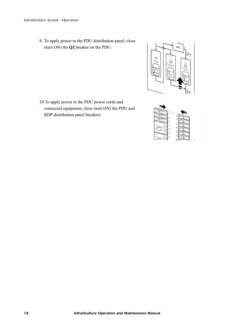
9. To apply power to the PDU distribution panel, close (turn ON) the Q2 breaker on the PDU.
10.To apply power to the PDU power cords and connected equipment, close (turn ON) the PDU and RDP distribution panel breakers.
18 InfraStruXure Operation and Maintenance Manual

Symmetra PX UPS (80kW)
Overview
The Symmetra PX UPS is a 10–80kW scalable, modular, N+1 UPS housed in a NetShelter VX enclosure. The enclosure supports up to nine power modules, which are replaceable without interrupting power to the load and easily slide into the enclosure.
The Symmetra PX UPS accepts 208-volt input from the PDU with System Bypass and returns 208-volt power to the PDU with System Bypass for distribution to equipment enclosures. Connection to and from the PDU with System Bypass is performed by APC Field Service Engineers during installation of your InfraStruXure system.
Front view
� Display interface—The display interface is attached to the name plate on the front door of the enclosure. It has an LCD, five-button interface, basic status lights, and a beeper.
� Leveling feet—The feet adjust for leveling the enclosure. All enclosures must be level before installation of the system begins.
� Documentation tray—The tray provides easy access to and storage for important documentation.
�
��
InfraStruXure Operation and Maintenance Manual 19

Symmetra PX UPS (80kW)—Overview
Front view (interior)
� Intelligence modules —The MIM (main intelligence module) is the main controller of the Symmetra PX UPS system. It reports status, configures the UPS, performs UPS diagnosis, manages power and batteries, controls general UPS performance, regulates output voltage, and shares output current. The RIM (redundant intelligence module) is the redundant controller. The RIM is identical to the MIM (same part number). It is responsible for system operation if the MIM fails or is removed. When you have two intelligence modules, you can remove one without affecting the load. However, when you only have one intelligence module, always put the system in maintenance bypass before removing it.
� Power module—The power modules can be removed without affecting the load. You can have up to nine power modules in each Symmetra PX UPS. Each power module can support up to 10kVA of power. Each time you add a power module, you increase the total capacity of your UPS. The total capacity cannot go above 80kVA (N+1).
� Access for data cables—This opening provides access for routing data cables to and from the management cards located in the card slots.
� Static switch module—The static switch module is a parallel power path in the Symmetra PX UPS. If a catastrophic failure occurs in the Symmetra PX UPS, the static switch is activated; input power bypasses the power modules; and power flows through the static switch to the connected load. The static switch has its own power supply and operates on a fail-safe signal from the intelligence modules. This module cannot be removed without affecting the load.
�
�
�
�
20 InfraStruXure Operation and Maintenance Manual

Symmetra PX UPS (80kW)—Overview
Front view (lower interior)
� System enable switch—This switch acts as the on/off switch for the Symmetra PX UPS. Once power is removed from the UPS correctly, this switch turns the UPS off.
� System power supply cards—These cards supply power to the MIM and RIM. The cards are on their own separate input and output bus and each can support the MIM and RIM if one of the cards fail.
�
�
�
�
�
�
�
�
� Card slots—The card slots are available for APC management/monitoring card accessories.
� Network Management Card—The Network Management Card communicates directly with the InfraStruXure Manager. The card connects to the InfraStruXure Manager Hub, using a network cable (provided with the InfraStruXure system).
� External switch gear monitoring card—This card monitors switch gear external to the Symmetra PX UPS and the InfraStruXure system.
� Display/computer interface card—This card provides communication between the Symmetra PX UPS display interface, a computer, and each intelligence module (MIM and RIM).
� Battery monitoring card—This card monitors the battery voltage and current in order to provide accurate runtime and battery status.
� Reserved for future use.
XR communications card—This card provides communication between the Symmetra PX UPS intelligence modules (MIM and RIM) and the XR Battery Enclosure (if applicable).
InfraStruXure Operation and Maintenance Manual 21

Operation
Display interface
You can use the display interface to configure settings, set alarm thresholds, and provide audible and visual alarms.
� LOAD ON LED When green, the Symmetra PX UPS is providing power to the load equipment.
� ON BATT LED When yellow, power is flowing through the static bypass switch and to the load equipment.
� BYPASS LED When yellow, power to the load is being supplied directly by the utility power source. The UPS has been removed from the circuit for maintenance or replacement.
� FAULT LED When red, an fault condition exists.
� LCD Displays alarms, status data, instructional help, and configuration items.
� UP and DOWN navigation keys
Selects menu items and accesses information.
� ENTER key Opens menu items and input changes to system parameters.
� HELP key Launches context-sensitive help.
ESC key Returns to previous screen displayed.
LOAD ON
ON BATT
BYPASS
FAULT
ESC
?
�
�
�
� � � ��
22 InfraStruXure Operation and Maintenance Manual

Symmetra PX UPS (80kW)—Operation
Navigating screens
From any screen, you can press the ESC key until you reach the Top-Level Status screen, which provides basic system status information.
Press the ENTER key from the Top Level Status screen to open the top-level menu screen. To view other screens press the ENTER key when the selector arrow (�) is next to screen you want to view.
The continue arrow (�) indicates that there are sub-menu screens. Press the UP and DOWN keys to navigate to those screens.
Press the UP and DOWN keys, and the ENTER key to move the Input arrow (�) to select and enter information.
Chrg 10%Load 000%115Vin 115Vout 50HzRuntime: 0hr 0m
Top-Level Status
ControlStatusSetupAccessories
LoggingDisplayDiagsHelp�
Top-Level Menu
Bat Voltage: 218.0VBat Capacity 100.0%Runtime: 01hr 30min16 Batts, 00Bad
Capacity: 10.0kVAFault Tolerance: n+2Total UPS Modules: 03Bad UPS Modules: 00
�
Low Batt Dur: 2minShutdwn Dly:Return Dly:Return Bat Cap:
�
20sec0sec0%
Low Batt Dur: 10minShutdwn Dly:Return Dly:Return Bat Cap:
20sec0sec0%
InfraStruXure Operation and Maintenance Manual 23

Symmetra PX UPS (80kW)—Operation
Top-Level Status Screen
After the display interface has established communication with the Symmetra PX UPS, the Top-Level Status Screen appears on the LCD. By default, the Top-Level Status Screen displays the following:
Top-Level Menu Screen
From the top-level menu Screen you can command, configure, and monitor the Symmetra PX UPS.
Charge Percentage The percentage of battery capacity that is available.
Load Percentage The percentage of system capacity that is being used to supply conditioned power to the connected load.
Input Voltage/Output Voltage/Input Frequency
The input voltage from the main power source, the output voltage supplied to the load equipment, and the frequency of the input power.
Run Time The runtime that can be expected of the batteries. The intelligence module calculates the runtime based on both the amount of power required by the load equipment and the capacity of the battery modules in the system.
Note
After the display interface has been inactive for a period of time (specified by the password time-out setting under the Display menu), the interface reverts to the Top-Level Status screen.
Chrg 100%Load 050%208Vin 208Vout 60HzRuntime: 0hr 30m
For information on specific screens accessed through the top-level menu screen, see pages 25–29.
ControlStatusSetupAccessories
LoggingDisplayDiagsHelp
24 InfraStruXure Operation and Maintenance Manual

Symmetra PX UPS (80kW)—Operation
Control screen
From the Control screen, you can select the following items:
Status screens
The Status screens display information regarding load, battery and power modules, voltage, and current.
UPS into Bypass Place into or return from maintenance bypass operation.
Do Self Test Initiate a system of self-tests and diagnostics.
Simulate Power Fail Simulate a power failure.
Graceful Reboot Turn off and start load equipment in an ordinary manner.
Graceful Turn Off Shut down load equipment in an orderly manner.
Start Runtime Cal Begin runtime calibration of the UPS.
Turn Load On/Off Apply power to or shut down the Symmetra PX UPS.
Status screen 1
VinVoutIout
The input voltage (V), output voltage (V), and output current (A) for each phase (1–3).
Status screen 2
%load assuming no redundancy
Percentage of the load in relation to the total capacity of all power modules.
Status screen 3
%load allowing for n+x redundancy
Percentage of the load, allowing for the redundancy in your system.
Status screen 4
Frequencies The input and output frequency in hertz (Hz).
Status screen 5
Batt Voltage Actual voltage of the batteries (volts).
Batt Capacity Percentage of battery capacity available.
Runtime The available runtime for battery operation in hours and minutes.
#Batts The number of installed battery modules.
#Bad The number of failed battery modules.
InfraStruXure Operation and Maintenance Manual 25
Symmetra PX UPS (80kW)—Operation
Status screen 6
Capacity: kVA The system load capacity.
Fault Tolerance The configured redundancy for your UPS (n+0, n+1, n+2...).
Total Pwr Modules The number of power modules installed.
Bad Pwr Modules
The number of failed power modules installed.
Status screen 7
Alarm Thresholds
Settings configured for the thresholds that trigger alarms.
Fault Tolerance n+0 The alarm threshold for reduced redundancy.
Runtime hr min The alarm threshold for reduced runtime.
Load: kVA Alarm indication of the load exceeding the configured redundancy.
Status screen 8
Self Test Status of the last self-test.
Lst Xfr Information on the last transfer to battery operation.
Status General UPS status.
IM Status of the main intelligence module.
RIM Status of the redundant intelligence module.
26 InfraStruXure Operation and Maintenance Manual

Symmetra PX UPS (80kW)—Operation
Setup screen
From the Setup screen, you can select the following items:
Shutdown Configure the following system shutdown conditions:
Low Batt Dur: Low battery duration is the time from low battery signal to the shutdown of the load.
Shutdwn Dly: Shutdown delay is the time from when the UPS receives a shutdown command (usually sent by a server) to the shutdown of UPS power to the load equipment. This delay allows load equipment time to finish shutdown processes.
Return Dly: Return delay is the amount of time the UPS wants to turn on after a power outage has ended.
Return Bat Cap: Return battery capacity is the minimum percentage of battery capacity required for the UPS to turn on.
Defaults Return all UPS settings to their default values.
Output Frequency Set the desired output frequency.
Alarms Redundancy: The state of redundancy that will trigger an alarm. Choices are:
• N+0—an alarm will occur only when there is more load than all functioning power modules can support;
• N+1—an alarm will occur when there are no spare power modules in good condition;
• N+2— an alarm will occur when there is only one functioning power module.
Load: When the load is greater than this threshold, an alarm will sound.
Runtime: When the time the UPS can power the load is less than this threshold, an alarm will sound. This alarm is the result of an increase in load or a decrease in battery capacity.
Bypass Set the conditions in which the UPS will automatically go into bypass operation.
Copy Copy the UPS settings.
InfraStruXure Operation and Maintenance Manual 27

Symmetra PX UPS (80kW)—Operation
Accessories screen
The Accessories screen is used only if the display interface is connected to the computer interface port at the back of the Symmetra PX UPS. From the Accessories screen, you can view the status of APC accessories connected to the UPS.
Logging screens
The Logging screen allows you to customize the Symmetra PX UPS log. The following items are accessible from this screen:
Other Self Test: Set the UPS to perform a self-test automatically at periodic intervals.
UPS ID: Provide a unique name for the UPS.
Vout Reporting: Set the reporting to the number of the tap to which the most significant load is wired on the output transformer.
Output: Set the UPS output voltage.
BatFrAmpHour: Set the Ampere-Hour rating of external battery enclosures that are not APC Symmetra XR Battery Enclosures.
View Log Point to an entry in the log and press the ENTER key to view a description of the event. The display logs the most recent 64 events.
View Statistics View statistics of the events logged.
Configure Logging Set the type of events that are recorded in the log. To log a type of event, choose On.
List Event Groups View the list of event types.• Power Events• UPS Control Events• User Activities• UPS Fault Events• MeasureUPS Events
For each group, press the Enter key to display each event listed under the group.
Clear Log Clear all events currently stored in the log.
28 InfraStruXure Operation and Maintenance Manual

Symmetra PX UPS (80kW)—Operation
Display screens
The Display screens allow you to customize the Symmetra PX UPS display interface. The following items are accessible from this screen:
Diag screens
The Diagnostic screens provide information for use in troubleshooting. The following items are accessible from this screen:
Help screens
To access the display interface context-sensitive help screens, press the ? key.
Date/Time Set the correct date (day:month:year) and time (hour:minute).
Password Protect the password against unauthorized configuration changes.
Information View the model number, serial number, date of manufacture, and revision number of the display interface.
Beeper Configure the audible alarm settings:
At UPS
At Disp
Vol
Click
Contrast Set the contrast on the LCD.
Config Personalize the Top-Level Status screen. Choose each line you want displayed from a list of options. To change a line, move the selection arrow to the line you want to change and press the ENTER key. Scroll up or down the list to find the data you want displayed and press the ENTER key to save your changes.Press the ESC key to discard your changes.
Fault & Diagnostics Lists any failures found.
Comm Bus Status If any status except ON or OK is displayed, a power module must be replaced. The Faults and Diagnostics screen will describe the location of the failed module.
Ext Device Status Lists external device status.
Frame Status If any status except ON or OK is displayed, a power module or battery must be replaced. If you do not have a redundant module installed, you must place the UPS in bypass operation before you remove an intelligence module.
InfraStruXure Operation and Maintenance Manual 29

Troubleshooting
This section lists all of the alarm and status messages that are displayed on the Symmetra PX UPS display interface. A suggested corrective action is listed with each message to help you troubleshoot problems. Contact APC Technical Support for assistance with complex problems.
See “APC Customer Support” on the back cover of this manual for contact information.
Note
More than one message may occur at the same time. Be sure to review all of the messages for a better understanding of the system condition.
Note
If the display interface reports a problem with a component, verify that the component is correctly installed in the Symmetra PX UPS.
If problems persist with the interface, see “How to Obtain Service” on page 91.
30 InfraStruXure Operation and Maintenance Manual

Symmetra PX UPS (80kW)—Troubleshooting
General status
Display Message Meaning Corrective Action
Input Freq outside configured range
The input frequency to the Symmetra PX UPS is outside the configured range. The output frequency will not synchronize with the input frequency. Normal bypass is not available.
Option 1: Improve the frequency of the incoming voltage.Option 2: Widen the range of the acceptable incoming frequency using the display interface. (Select Startup, Setup, Output, Freq Select)Option 3: Proceed with startup—normal bypass is not available.
AC adequate for UPS but not for bypass
The Symmetra PX UPS will function on-line with the input voltage, but in the event that bypass is required, the input voltage is not adequate to power the load equipment.
Option 1: Improve the incoming voltage.Option 2: Proceed with startup—normal bypass is not available.
Low/No AC input, startup on battery
Input voltage is not adequate to start the Symmetra PX UPS. If start-up proceeds, the Symmetra PX UPS will function in battery operation.
Option 1: Cancel start-up until acceptable input voltage is present.
Intelligence Module inserted
An Intelligence Module has been installed into the Symmetra PX UPS.
No corrective action necessary.
Intelligence Module removed
An Intelligence Module has been removed from the Symmetra PX UPS.
Check that the intelligence modules are properly inserted and that the fastening screw is tight.
Redundant Intelligence Module inserted
An Intelligence Module has been installed into the Symmetra PX UPS.
No corrective action necessary.
Redundant Intelligence Module removed
An Intelligence Module has been removed from the Symmetra PX UPS.
Check that the intelligence modules are properly inserted and that the fastening screw is tight.
# of Batteries changed since last ON
At least one battery module has been added or removed from the UPS since the last time the Pwr ON command was used.
No corrective action necessary.
# of Pwr modules changed since last ON
At least one power module has been added or removed from the UPS since the last time the Pwr ON command was used.
Check that all power modules are properly inserted, the two fastening screws are tight, and the locking latch is engaged.
# of Batteries increased At least one battery module has been added to the system.
No corrective action necessary.
# of Batteries decreased At least one battery module has been removed from the system.
Ensure that all battery units are properly inserted.
InfraStruXure Operation and Maintenance Manual 31

Symmetra PX UPS (80kW)—Troubleshooting
Display Message Meaning Corrective Action
# of Pwr Modules increased
At least one power module has been added to the system.
No corrective action necessary.
# of Pwr Modules decreased
At least one power module has been removed from the system.
Check that all power modules are properly inserted, the two fastening screws are tight, and the locking latch is engaged.
# of External Battery Cabinets increased
At least one external battery cabinet has been connected to the Symmetra PX UPS.
No corrective action necessary.
# of External Battery Cabinets decreased
At least one external battery cabinet has been disconnected from the Symmetra PX UPS.
Ensure that all XR Battery Enclosure’s communication cables are properly connected and that the LEDs are illuminated on the XR communication cards.
Redundancy Restored A loss of power module redundancy occurred and the redundancy has been restored. Either additional modules have been installed or the load has been reduced.
No corrective action necessary.
32 InfraStruXure Operation and Maintenance Manual

Symmetra PX UPS (80kW)—Troubleshooting
General fault
Display Message Meaning Corrective Action
Need Bat Replacement One or more battery units need to be replaced.
See “Battery replacement” on page 49.
The Redundant Intelligence Module is in control
The Main Intelligence Module has failed, and the Redundant Intelligence Module is functioning as the primary intelligence module.
Replace the Main Intelligence Module. See “How to replace an intelligence module” on page 40.
UPS Fault A fault has occurred in a power module. This will always occur with a power module failure message.
Contact APC Technical Support. See the back cover of this manual for contact options.
On Battery The Symmetra PX UPS has transferred to battery operation due to the input going out of acceptable range. At this time the batteries will discharge until the input is restored to an acceptable range.
No corrective action necessary.Note: Runtime is limited in duration. Prepare to shut down the Symmetra PX UPS and the load equipment or restore incoming voltage.
Shutdown or unable to transfer to batt due to overload
The Symmetra PX UPS has shut down because an overload occurred and bypass is not available.
Option 1: Reduce the load to eliminate overload.Option 2: If possible, add power modules to eliminate overload.Option 3: Replace failed power modules to eliminate overload.
See “Specifications” on page 43 for overload specifications.
Load Shutdown from Bypass. Input Freq/Volts outside limits
The Symmetra PX UPS has transferred to battery operation because the input is out of acceptable range.
Correct the input voltage problem.
Fault, Battery Charger Failure The battery charger in one or more of the power modules failed.
See “How to replace a power module” on page 38.
Fault, Internal Temp exceeded normal limits
The temperature of one or more battery units has exceeded system specifications.
Ensure that the ambient temperature meets the specifications of the system.
Input circuit breaker tripped open
The input circuit breaker on the Symmetra PX UPS is open. Input voltage is disconnected to the Symmetra PX UPS.
Option 1: If this occurs with an overload condition, decrease the load and reset the breaker.Option 2: If no overlaod condition exists, reset the breaker. If it trips open again, contact APC Technical Support. See the back cover of this manual for contact options.
System level fan failed A cooling fan in the Symmetra PX UPS failed.
Contact APC Technical Support. See See the back cover of this manual for contact options.
InfraStruXure Operation and Maintenance Manual 33

Symmetra PX UPS (80kW)—Troubleshooting
Module failure
Threshold alarm
Display Message Meaning Corrective Action
Bad Battery Module A battery module has failed and requires replacement.
Refer to “Battery replacement” on page 49 for more information.
Bad Power Module A power module has failed and requires replacement.
Refer to “How to replace a power module” on page 38 for more information.
Intelligence Module is installed and failed
The Main Intelligence Module has failed and requires replacement.
Replace the Main Intelligence Module. See “How to replace an intelligence module” on page 40 for more information.
Redundant Intelligence Module is installed and failed
The Redundant Intelligence Module has failed and requires replacement.
Replace the Redundant Intelligence Module. See “How to replace an intelligence module” on page 40 for more information.
Display Message Meaning Corrective Action
Redundancy has been lost The Symmetra PX UPS no longer detects redundant power modules. One ore more power modules have failed, or the load has increased.
Option 1: If possible, install additional power modules.
Redundancy is below alarm threshold
Actual power module redundancy has fallen below user-specified redundancy alarm threshold. Either power module(s) failed or the load increased.
Option 1: If possible, install additional power modules.
Runtime is below alarm threshold
The predicted runtime is lower than the user-specified minimum runtime alarm threshold. Either the battery capacity has decreased, or the load has increased.
Option 1: Allow the battery modules to recharge.Option 2: If possible, increase the number of battery modules.
Load is above kW alarm threshold
The load has exceeded the user-specified load alarm threshold.
Option 1: Use the display interface to raise the alarm threshold.
Load is No Longer above Alarm Threshold
The load exceeded the load alarm threshold and the situation has been corrected either because the load decreased or the threshold was increased.
No corrective action necessary.
Min Runtime Restored The system runtime dropped below the configured minimum and has been restored. Additional battery modules were installed, the existing battery modules were recharged, the load was reduced, or the threshold was raised.
No corrective action necessary.
34 InfraStruXure Operation and Maintenance Manual

Symmetra PX UPS (80kW)—Troubleshooting
Bypass
Display Message Meaning Corrective Action
Bypass is not in range (either freq or voltage)
The frequency or voltage is out of acceptable range for bypass. This message occurs when the Symmetra PX UPS is online, and indicates that the bypass mode may not be available if required.
Option 1: Decrease the sensitivity to input frequency. (Select Startup, Setup, OutputFreq, and select a value).Option 2: Correct the input voltage to provide acceptable voltage and/or frequency.
Backfeed contactor stuck in OFF position
The Symmetra PX UPS is stuck in the bypass position and cannot go on-line.
Contact APC Technical Support. See See the back cover of this manual for contact options.
Backfeed contactor stuck in ON position
The Symmetra PX UPS is stuck in the on-line position and cannot go to bypass.
Contact APC Technical Support. See See the back cover of this manual for contact options.
UPS in bypass due to internal fault
The Symmetra PX UPS has transferred to bypass mode because a fault has occurred.
Contact APC Technical Support. See See the back cover of this manual for contact options.
UPS in bypass due to overload The load exceeded the system power capacity. The Symmetra PX UPS has switched to bypass mode.
Option 1: Decrease the load.Option 2: If possible, add a power module to the system.
System is in Maintenance Bypass
The Symmetra PX UPS is in bypass because it has been commanded into bypass or due to an internal fault.
No corrective action necessary.
Fault, Bypass Relay Malfunction
The bypass relay has malfunctioned. Contact APC Technical Support. See See the back cover of this manual for contact options.
InfraStruXure Operation and Maintenance Manual 35

Maintenance
Handling and transport
Follow these guidelines if you need to move the Symmetra PX UPS to another location.
Remember to reinstall the power modules after the Symmetra PX UPS has arrived at its destination.
Module replacement
You can replace power modules and intelligence modules:• If a power module fails and the load conditions and settings of the UPS support redundancy, the
failed module can be replaced without interrupting power to the load equipment.• If a functioning intelligence module is already installed, you can replace a redundant
intelligence module without interrupting the power to the load.
Warning
Always remove all power modules before moving the Symmetra PX UPS to avoid damage during transport. This warning applies anytime the Symmetra PX UPS is moved—even a very short distance, by itself or as part of a InfraStruXure installation.
36 InfraStruXure Operation and Maintenance Manual

Symmetra PX UPS (80kW)—Maintenance
How to obtain replacement modules
To obtain a replacement module, contact APC Customer Support..
Follow the procedure below so that the APC Customer Support representative can assist you promptly:
1. In the event of a module failure, the display interface may display additional “fault list” screens. Press any key to scroll through these fault lists, record the information, and relay it to the representative.
2. If possible, call APC Customer Support from a telephone that is within reach of the Symmetra PX UPS display interface so that you can gather and report additional information to the representative.
3. Be prepared to provide a detailed description of the problem. A representative will help you solve the problem over the telephone, if possible, or will give you a return material authorization (RMA) number. If a module is returned to APC, this RMA number must be clearly printed on the outside of the package.
4. If the Symmetra PX UPS is within the warranty period, repairs will be performed free of charge. If it is not within the warranty period, there will be a charge for repair. Review APC’s warranty policy.
5. If the Symmetra PX UPS is covered by an APC service contract, have that information available and give it to the representative.
See “APC Customer Support” on the back cover of this manual for phone numbers.
See “Warranty” on page 79.
InfraStruXure Operation and Maintenance Manual 37

Symmetra PX UPS (80kW)—Maintenance
How to replace a power module
The display interface indicates the location of the faulty power module (rows 1 through 5).
To remove the faulty power module:
1. To deactivate the power module, turn the knob (with arrow pointing toward the module) to the left until the arrow points downward.
2. Turn the spring-activated finger screws (one at either side of the module) until they pop out.
3. With one person on each side of the UPS enclosure, pull the power module outward until it is fully extended in the locked position.
4. With the power module resting in the UPS enclosure, release the lock by depressing the latch on each side of the power module.
5. Pull the power module away from the UPS enclosure.
Warning
Only qualified, APC-trained users may replace power modules.
Note
You will need two people to perform this procedure.
38 InfraStruXure Operation and Maintenance Manual

Symmetra PX UPS (80kW)—Maintenance
To install the new power module:
1. With one person on each side of the power module, push the power module all the way into the Symmetra PX UPS enclosure. (The power module is self-guiding.)
2. Turn the finger screws clockwise to fasten.
3. Turn the knob clockwise until the arrow points toward the power module to re-activate the power module.
4. Verify that the Symmetra PX UPS display interface shows a message saying that it has registered the installation.
.
Note
You will need two people to perform this procedure.
Note
If your Symmetra PX UPS includes a redundant power module, the failed module can be replaced without interrupting power to the connected equipment.
InfraStruXure Operation and Maintenance Manual 39

Symmetra PX UPS (80kW)—Maintenance
How to replace an intelligence module
To remove the faulty intelligence module:
1. Loosen the two Phillips screws at either side at the top of intelligence module. By loosening the left-hand top screw, you will deactivate the intelligence module as soon as the tab becomes loose.
2. Carefully remove the intelligence module from the enclosure by pulling outward on the handle.
To install the new intelligence module:
1. Carefully position the intelligence module between the grooves in the empty slot at the top of the Symmetra PX UPS enclosure and slide the module inward.
2. Tighten the two Phillips screws to secure the intelligence module to the enclosure. Once the tab on the top left is flush with the enclosure, the intelligence module will reactivate.
3. Verify that the Symmetra PX UPS display interface shows a message reporting that an intelligence module was inserted.
Note
A redundant intelligence module can be replaced without interrupting power to the connected equipment, if another functioning intelligence module is already installed.
40 InfraStruXure Operation and Maintenance Manual

Symmetra PX UPS (80kW)—Maintenance
How to replace cards
1. Loosen the two Phillips screws at each side of the card.
2. Carefully pull the card outward.
3. Verify that the UPS display interface shows a message reporting that it has registered the installation.
Replacement parts
Note
Reverse steps 1 and 2 in the above procedure to install a new card.
Replacement Parts and Numbers
10kW Power Module SYPM10KE
40kW Symmetra PX UPS Only SY40K4OE
Battery Module SYBTJ4
Battery Monitoring Card SYCBTMON
Battery Unit SYBTJU1
Display and Computer Interface Card SYCDCI
Intelligence Module SYMIM4
Network Management Card AP9617
Switch Gear Monitoring Card SYCSGMON
Symmetra PX UPS Static Switch Module SYSSW40KF
System ID Card SYCSYSID
System Power Supply Card SYCSPS
XR Communication Card SYCXRCOM
InfraStruXure Operation and Maintenance Manual 41

Symmetra PX UPS (80kW)—Maintenance
How to return modules to APC
Call APC Customer Support to obtain an RMA number.
To return a failed module to APC, pack the module in the original shipping materials, and return it by insured, prepaid carrier. The APC Customer Support technician will provide the address. If you no longer have the original shipping materials, ask the technician about obtaining a new set. Pack the module properly to avoid damage in transit. Never use styrofoam beads or other loose packaging materials when shipping a module. The module may settle in transit and become damaged. Enclose a letter in the package with your name, RMA number, address, a copy of the sales receipt, description of the problem, a phone number, and a check as payment (if necessary).
See “APC Customer Support” on the back cover of this manual for phone numbers.
Note
Damages sustained in transit are not covered under warranty.
42 InfraStruXure Operation and Maintenance Manual

Specifications
Electrical
Full load output power
Nominal input voltage
Nominal output voltage
Minimum input voltage (mains operation)
Minimum input voltage (bypass operation)
Charging power at Minimum input voltage
Charging power at Nominal input voltage
Efficiency at Nominal
Efficiency at minimum mains
Power Factor
Nominal battery voltage (+/-)
End of discharge battery voltage (+/-)
Full load output current (at nominal output voltage)
Full load input current (at nominal input voltage, fully charged batts)
Max input current (at nominal input voltage, charging batts)
Current limited input current (at minimum input voltage, Charging batts)
Max steady state load input current (at minimum input voltage, fully charged batts)
External battery input: full load DC current
External battery input: maximum DC current
Overload capacity
Overload capacity2 (Mains)
Overload capacity3 (Battery)
Overload capaicty4 (Bypass)
Overload capacity5 (Bypass) 1000% for 500ms
InfraStruXure Operation and Maintenance Manual 43

Symmetra PX UPS (80kW)—Specifications
Output current - Overload1
Output current - Overload2
Input current - Overload2 (Nominal Mains)
Output current - Overload3
Bypass current - Overload4(Nominal Bypass Mains)
Output current - Overload5
Physical
Audible Noise at 1 meter from surface
Dimensions(W × D × H)
Weight - Fully Loaded
Heat Dissipation—Fully Loaded
Compliance Specifications
UPS withstand rating
Approvals
44 InfraStruXure Operation and Maintenance Manual

XR Battery Enclosure
Overview
The XR Battery Enclosure adds runtime to your Symmetra PX UPS. Each XR Battery Enclosure holds up to eight battery modules, providing approximately 24 minutes of additional runtime, assuming a 0.8 power factor, at a full 40kVA load. You can attach up to four XR Battery Enclosures to a single Symmetra PX UPS. Connection and installation of the XR Battery Enclosure is performed by APC Field Service Engineers.
InfraStruXure Operation and Maintenance Manual 45

XR Battery Enclosure—Overview
Front view (interior)
� DC disconnect breaker—This breaker controls the flow of DC power on the DC bus. The breaker is an over-current device that protects the system from a fault on the DC bus.
� Address switch—The switch sets the address of your XR Battery Enclosure when you have multiple XR Battery Enclosures in your system.
� XR communications card—This card provides communication between the XR Battery Enclosure and the Symmetra PX UPS or additional XR Battery Enclosures.
� Battery monitoring cards—These cards monitor the battery voltage and current in order to provide accurate runtime and status of the batteries.
� Power supply card—Supplies power to the monitoring cards in the XR Battery Enclosure.� Battery module—A battery module consists of four battery units. Battery modules are located
on the four shelves below the power modules, and can be removed without affecting the load. The number of battery modules determines the runtime of a particular load. A battery module provides six minutes of runtime to one power module at full load (assuming a 0.8 load power factor). You can add more battery modules than power modules, resulting in an increase in runtime.
�
�
��
��
46 InfraStruXure Operation and Maintenance Manual

Troubleshooting
This section will help you to solve most problems. If the problem persists, contact APC Customer Support.
Display Message Meaning Corrective Action
The battery monitor board LEDs do not illuminate or the display interface reports an inaccurate number of XR Battery Enclosures.
An XR Battery Enclosure is not recognized.
Check that the Communications cable is connected, and that the XR Selector Switch is in the correct position. Ensure that the power supply card is properly seated.
The display interface displays inaccurate number of battery units.
Unrecognized battery units in your configuration.
Insure that all battery units are correctly installed.
The display interface reports a bad battery unit.
A failed battery unit has been detected.
See “Battery replacement” on page 49.
InfraStruXure Operation and Maintenance Manual 47

Maintenance
Replacement parts
How to replace a card
1. Loosen the Phillips screw at each side of the card.
2. Carefully pull the card outward.
3. Verify that the UPS display interface shows a message reporting that it has registered the removal.
4. Install the new card, carefully sliding the card on the guide rails in the card slot.
5. Re-insert the Phillips screw at each side of the card and tighten.
6. Verify that the UPS display interface shows a message reporting that it has registered the installation.
Part Part Number
Battery Unit SYBTJU1
System Power Supply Card SYCSPS
Battery Monitoring Card SYCBTMON
XR Communication Card SYCXRCOM
48 InfraStruXure Operation and Maintenance Manual

XR Battery Enclosure—Maintenance
Battery replacement
If a battery unit fails less than six months from the time of installation, replace the faulty battery unit. If a battery unit fails after working for six months or more, replace the entire battery module (four battery units).
You can replace battery units without interrupting power to the connected load equipment if the Symmetra PX UPS is not in on-battery operation. When working with batteries, follow these safety instructions:
Warning
Only qualified, APC-trained personnel should replace battery units.
Warning
Risk of Electrical Shock and Energy Hazard!
To replace a battery unit, use only the same APC Battery Unit, model SYBTU1.
Before replacing batteries, remove conductive jewelry such as chains, wrist watches and rings. High short-circuit current through conductive materials could cause severe burns.
Do not dispose of batteries in a fire. The batteries may explode.
Do not open or mutilate batteries. Released electrolyte is toxic and harmful to the skin and eyes.
Heavy
Each battery unit is 23kg. Use two people to replace battery units.
InfraStruXure Operation and Maintenance Manual 49

XR Battery Enclosure—Maintenance
How to obtain replacement batteries
To obtain a replacement batteries, contact APC Customer Support..
Follow the procedure below so that the APC Customer Support representative can assist you promptly:
1. In the event of a failure, the display interface may display additional “fault list” screens. Press any key to scroll through these fault lists, and record the information, to report it to the representative. Be prepared to provide a detailed description of the problem.
2. If the XR Battery Enclosure is covered by an APC service contract, have that information available to give to the representative.
3. If possible, call APC Customer Support from a telephone that is within reach of the display interface. This will help to gather and report additional information to the representative.
4. A representative will help you solve the problem over the telephone, if possible, or will give you a return material authorization (RMA) number. If a battery is returned to APC, this RMA number must be clearly printed on the outside of the package.
5. If the XR Battery Enclosure or battery unit is within the warranty period, repairs will be performed free of charge. If it is not within the warranty period, there will be a charge for repair. Review APC’s warranty policy.
See the back cover of this manual for contact options.
50 InfraStruXure Operation and Maintenance Manual
XR Battery Enclosure—Maintenance
How to replace a battery unit
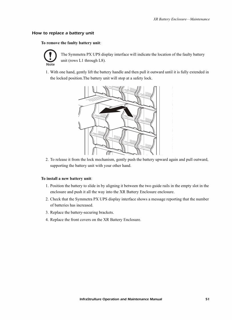
To remove the faulty battery unit:
1. With one hand, gently lift the battery handle and then pull it outward until it is fully extended in the locked position.The battery unit will stop at a safety lock.
2. To release it from the lock mechanism, gently push the battery upward again and pull outward, supporting the battery unit with your other hand.
To install a new battery unit:
1. Position the battery to slide in by aligning it between the two guide rails in the empty slot in the enclosure and push it all the way into the XR Battery Enclosure enclosure.
2. Check that the Symmetra PX UPS display interface shows a message reporting that the number of batteries has increased.
3. Replace the battery-securing brackets.
4. Replace the front covers on the XR Battery Enclosure.
Note
The Symmetra PX UPS display interface will indicate the location of the faulty battery unit (rows L1 through L8).
InfraStruXure Operation and Maintenance Manual 51

Specifications
Electrical
Battery Voltage (nominal) +/- 192Vdc
Battery Current (at full load) 115A at +/- 192Vdc
Maximum Current (at end of discharge)
137A at +/- 160Vdc
If external batteries are customer-supplied, see the data provided by the manufacturer.
Physical
Dimensions (W×D×H) 23 × 36 × 81in (595× 915×2050mm)
Weight (fully loaded) 2458lb (1115kg)
Color Black
Operating
Environment Protected from water and conductive contaminants.
Storage Elevation (for aircraft transportation)
32,808ft (10 000m)
Relative Humidity (for operating and storage)
95% non-condensing
Operating Temperature 32–104°F (0–40°C)
52 InfraStruXure Operation and Maintenance Manual

PDU with System Bypass and RDP
Overview
APC’s 80kW PDU with System Bypass provides distribution and management of electrical power. The PDU with System Bypass has the capacity of 80kW, accepts 208, 480, or 600V, 3-phase input, and distributes 208V, 3-phase power to equipment racks and Remote Distribution Panels (RDPs). The RDPs sit in the top 10U of specially-designed NetShelter VX enclosures and distribute power to equipment racks. The PDU with System Bypass is housed in a specially-designed 23-inch NetShelter enclosure. Each 80kW PDU with System Bypass has 30, 20-amp pole positions available for feeding equipment racks and four, 80-amp pole positions available for feeding RDPs. Each RDP has 39, 20-amp pole positions available for feeding equipment racks and one, 80-amp pole position that back-feeds the RDP.
Power Cord Feeding the Remote Distribution Panel Power Cords Feeding
the Equipment Racks
Remote Distribution Panel (RDP)l
80 kW PDU with System Bypass
Power Cords Feedingthe Equipment Racks
NetShelter VX Enclosure
42-Position Circuit Breaker Panel
30, 20A PolePositionsAvailable forEquipment
4, 80A CircuitBreakers Sub-Feeding the RDPs
39, 20A PolePositions Available forEquipment
1, 3-Pole, 80A Breaker Back-Feeding the RDP
InfraStruXure Operation and Maintenance Manual 53

PDU with System Bypass and RDP—Overview
PDU front view (exterior)
� PDU Power Cable Shielding Trough—The PDU trough is specially-designed to accommodate the power cords exiting the roof of the PDU.
� Power cable—These power cables feed equipment racks; they are fed through knockout panels on the top (or bottom) of the PDU. The power cables consist of five wires: three phases, one neutral, and one ground. The number of power cables installed in the PDU depends on your system configuration. Each power cable has a NEMA L21-20 outlet, which accepts a variety of APC InfraStruXure accessories, including Rack PDUs and the Rack ATS.
� RDP power cable—These power cables feed RDPs; they are fed through knockout panels on the top (or bottom) of the PDU. The power cables consist of five wires: three phases, one neutral, and one ground. You can have up to four RDP power cables. Each power cable has an IEC 309 outlet, which connects to another RDP power cable fed from the RDP with an IEC 309 plug.
� Display interface—The display interface is attached to the name plate on the front door of the enclosure. It has an LCD, five-button interface, basic status lights, and a beeper.
� Cable access holes—Both side panels on the PDU have cable access holes for Symmetra PX UPS input and output wiring. During installation, the APC Field Service Engineer will exchange side panels between the PDU and the Symmetra PX UPS so that the adjacent sides of the two units will have panels with cable access holes.
� Leveling feet—The feet adjust for leveling the enclosure. All enclosures must be level before installation of the system begins.
�
�
�
�
�
�
54 InfraStruXure Operation and Maintenance Manual

PDU with System Bypass and RDP—Overview
Front view (interior)
� Ground lugs—The main input switch, dual feed input switch, and the cross tie output breaker have lugs to connect a protective earth (PE) ground wire. The main input switch also has a lug to connect a Grounding Electrode Conductor (GEC).
� Main input switch—Power from the main power source connects to your system at the main input switch. The switch accepts 208V, 480V, or 600V input and requires 3-wire input conductors for PDUs with a transformer and 4-wire input conductors for PDUs without a transformer.
�
�
�
�
�
�
�
� Optional dual feed input switch— If you ordered a PDU that accepts input power from two different sources, your secondary power source connects to your system at the dual feed input switch. The switch requires 208V input and 4-wire input conductors.
� Optional cross tie output breaker—The cross tie is a 4-pole breaker that outputs 208V to a dual feed input switch on a different system. The cross tie breaker allows systems to be cascaded for redundancy.
� PDU monitoring unit breaker—Power supplied to the PDU monitoring unit is controlled through this breaker.
� Fuses—These fuses protect the silicon-controlled rectifiers in the UPS bypass static switch. The fuses are only present on dual-fed PDUs and single-fed PDUs without a transformer.
� Optional bottom feed—If you ordered main input wiring to be routed under the floor, these terminal blocks are your connection to the main input switch, dual feed input switch, and cross tie output breaker.
InfraStruXure Operation and Maintenance Manual 55

PDU with System Bypass and RDP—Overview
Front view (door open)
�
��
� Wraparound maintenance bypass panel—The maintenance bypass panel has three breakers, which allow the UPS to be electrically isolated from the main power source, while maintaining the power panels. The input breaker is labeled Q1, the output breaker is labeled Q2, and the maintenance bypass breaker is labeled Q3. The label on the maintenance bypass panel of the PDU illustrates the power flow.
� UPS input and output cables—The cables that connect the PDU to the UPS are shipped coiled on the floor of the PDU. The input cables consist of 5 wires: 3 phases, 1 neutral, and one protective earth. The output cables consist of 4 wires: 3 phases and 1 neutral. If you ordered the optional dual-feed, you will also have bypass cables, which consist of 4-wires: 3 phases and one neutral. Each wire is labeled and corresponds to a lug on the Symmetra PX UPS bus bars. During installation, the Field Service Engineer will connect the PDU to the UPS.
� Optional bottom-feed cable access—These knock-outs are for bottom-feed power cables and RDP cables. If you ordered a PDU to accommodate under-floor wiring, your power cables for equipment racks and RDPs will exit the PDU from these cable access holes.
56 InfraStruXure Operation and Maintenance Manual

PDU with System Bypass and RDP—Overview
Rear view (interior)
� 42-position circuit breaker panel—Each PDU has a circuit breaker panel with 42 pole positions. Each pole provides power at 120 volts L-N or 208 volts L-L. The amperage each position provides depends on the size of the circuit breaker used.
� Panel current sensors—Wires that feed the distribution panel pass through these current sensors, providing data to the PDU monitoring unit.
� PDU monitoring unit—The PDU has several current and voltage monitoring boards that report to a central board assembly located in the PDU monitoring unit. The PDU monitoring unit has one 10BaseT (CAT5) connection to the InfraStruXure Manager, four contact closure connections for user-definable contacts, and a choice of three different connections (contact closure, 24VAC, 24VDC) for an EPO switch.
� Fans—The fans cool the PDU from the heat generated by the transformer.
� Input transformer—The delta-wye transformer installed in your PDU is based on your input voltage (208V, 480V, or 600V input). The output of the transformer feeds the input circuit breaker of the maintenance bypass panel.
� Load test ports—The load test ports are an available option on the PDU. The load test bank connector allows a UPS system to be load-tested to ensure the system will operate according to specifications if a power outage occurs.
�
�
�
�
�
�
�
InfraStruXure Operation and Maintenance Manual 57

PDU with System Bypass and RDP—Overview
RDP front view (door open)
�
�
�
�
� Power cable—The power cables are fed through knockout panels on the roof of the RDP enclosure. The power cables consist of five wires: three live, one neutral, and one ground. The number of power cables installed in the RDP depends on your system configuration. Each power cable has a NEMA L21-20 outlet, which accepts a variety of APC InfraStruXure accessories, including Rack PDUs and the Rack ATS.
� RDP power cable—This power cable attaches to the RDP power cord from the PDU. The power cable consists of five wires: three phases, one neutral, and one ground. It has an IEC 309 plug, which connects to an outlet on the RDP power cable from the PDU.
� Available rack space—The RDP provides 32U of space in the lower part of the enclosure for installing rack-mount equipment.
� 42-position circuit breaker panel—Each RDP has one circuit breaker panel with 42 pole positions. Each pole provides power at 120 volts L-N or 208V L-L. The amperage each position provides depends on the size of the circuit breaker used.
58 InfraStruXure Operation and Maintenance Manual

Operation
Display interface
You can use the display interface to configure settings, set alarm thresholds, and provide audible and visual alarms.
ESC
?
LoadOn
CheckLog
Bypass
Alarm
� � ��� � � �
� LOAD ON LED When green, all output phases are within the limits specified by the output alarm limit thresholds.
� CHECK LOG LED
When yellow, at least one new alarm condition has been detected.
� BYPASS LED When yellow, power to the load is being supplied directly by the utility power source. The UPS has been removed from the circuit for maintenance or replacement. Bypass breakers on the PDU function as input breakers to protect the load equipment.
� ALARM LED When red, an alarm condition exists.
� LCD View alarms, status data, instructional help, and configuration items.
� UP and DOWN navigation keys
Selects menu items and accesses information.
� ENTER key Opens menu items and input changes to system parameters.
� HELP key Launches context-sensitive help. Press the Help key for information about each item on the screen and for instructions on how to perform certain tasks (i.e. placing the UPS into Maintenance Bypass operation.)
ESC key Returns to previous screen displayed.
InfraStruXure Operation and Maintenance Manual 59

PDU with System Bypass and RDP—Operation
Top-level status screens
After displaying a brief start-up screen after system start-up, the display interface scrolls automatically and continuously through four screens of basic status information. Press the Up and Down arrow keys to interrupt the automatic scrolling to view a specific status screen.
Top-level Menu screen
On any top-level status screen, press the ENTER key to open the top-level Menu screen.
Navigating through screens
To open any screen, press the Up and Down arrow keys until the selector arrow (�� rests next to your desired selection. Press the ENTER key to view the selected screen.
Volts InL1-2: 000L2-3: 000L3-1: 000
Total Output LoadingkW: 000.0 PF:0.00kVA:000.0 %LD: 000Freq: 00.0
Load CurrentL1: 000 Neut: 000L2: 000L3: 000 Gnd: 00.0
Active Alarm: 01of11Input TransformerTemperature Too High
Volts OutL1-2: 000L2-3: 000L3-1: 000
Note
If the display interface is inactive for the time specified as the Time-out setting, the interface reverts to the initial basic monitoring screens.
For descriptions of the top-level menu choices, see the individual sections starting on page 62.
Load-Meter AlarmsVolt-Meter PanelContacts ConfigBreakers Help
Contacts In: 02of04Name: User Switch #2Normal: OpenStatus: Open
Load-Meter AlarmsVolt-Meter PanelContacts ConfigBreakers Help
�
60 InfraStruXure Operation and Maintenance Manual

PDU with System Bypass and RDP—Operation
When configuring settings, press the UP and DOWN arrow keys until the selector arrow (�� rests next to the setting you want to change, and press the Enter key. If the setting is a list of choices, an input arrow (�� will appear next to the setting. Press the Up and Down arrow keys until your desired change is listed. Press the Enter key to select the setting.
On some screens, continue arrows (�� indicate that there are additional screens to view in the category. Press the Up or Down arrow key to view the additional screens.
Password-protected screens
When configuring or changing settings, you will be prompted for your password. To enter your password:
1. Press the Up or Down arrow key until the correct letter is displayed and then press the Enter key.
2. Press the Enter key twice after you are finished entering your password.
Contacts In: 02of04Name: User Switch #2Normal: OpenStatus: Open
�
Product DataFactory DefaultsFirmware Updates
System/NetworkElectrical ConfigurationPanel ConfigurationManufacturer Data
�
Note
After pressing the ENTER key, the character you entered will be displayed as an asterisk and the input arrow will move to the next space for you to select the next password character.
See “System Password” on page 69 for information about changing your password.
Enter Password:*******
InfraStruXure Operation and Maintenance Manual 61

PDU with System Bypass and RDP—Operation
Load-Meter screen
From the Load-Meter screen, you can select the following items:
Volt-Meter screen
From the Volt-Meter screen, you can select the following items:
Total Load by Phase
The load supported by each phase in kVA, in RMS current (Irms), and as a percentage of the maximum allowable load (%LD).
Total Load Summary
For the total load supported:• kW: The power provided, in kilowatts • kVA: The actual power drawn by the load, in kilovolt-amperes• Freq: Frequency • PF: The power factor, which affects the power available to the load.• %LD: The load as a percentage of the maximum allowable load.
Power Factor For each phase:• kVA: The actual power drawn by the load, in kilovolt-amperes (kVA).• kW: The power, in kilowatts provided by the phase.• PF: The power factor (kW/kVA), which affects the power available to
the load.
Output Voltage Displays each phase-to-phase output voltage (e.g. L1-2 for phase L1 to phase L2) and each phase-to-neutral output voltage (e.g. L1 for phase L1 to neutral).
Input Voltage Displays each phase-to-phase input voltage (e.g. L1-2 for phase L1 to L2), and, if your service transformer is a Wye transformer, each phase-to-neutral input voltage (e.g. L1 for phase L1 to neutral).
Bypass Voltage Displays each phase-to-phase bypass (dual-feed input) voltage (e.g. L1-2 for phase L1 to phase L2) and each phase-to-neutral bypass voltage (e.g. L1 for phase L1 to neutral).
Displays only on PDUs that have a dual feed.
62 InfraStruXure Operation and Maintenance Manual

PDU with System Bypass and RDP—Operation
Contacts screen
Use the Contacts screen to display and configure information on the contact inputs (dry contacts).
Breakers screen
Use this screen to view the status of the system and PDU breakers.
Contact In Scroll through the list to display information about each of the installed contact inputs. For example, 02of04 displays information about the second of four installed contact inputs.
Name The name of this contact input.Maximum: 14 alphanumeric characters
Normal The normal position of this contact input, either Open or Closed.
Status The position of this contact input. If the condition is not the normal position, an alarm condition occurs.
For more information, see “How to connect contacts to the PDU Monitoring Unit” on page 72.
UPS & System Bypass
Reports the operation mode of the UPS and the state of the Q1, Q2, and Q3 breakers on the PDU.
Main Input Reports status of PDU Main Input Breaker (Open or Closed). Under normal operation, this breaker will be Closed.
Bypass Input Reports status of the PDU dual feed input switch (Open or Closed). Under normal operation, this breaker will be Closed.
Cross Tie Reports status of the cross tie output breaker (Open or Closed).Under normal operation, this breaker will be Closed.
InfraStruXure Operation and Maintenance Manual 63

PDU with System Bypass and RDP—Operation
Alarms screen
View Active Alarms. Use this option of the Alarms screen to display active alarms (alarms that have not been resolved). Scroll through the list to view each active alarm.
Alarm/Event Log. Use this selection of the Alarms screen to access the following options:
Alarm Setup. Use this option of the Alarms screen to access the following options:
New Logged Items Display a description and the date and time of each alarm that occurred since the last time this option was used.
• The most recent alarm is displayed initially. To move to the previous alarm, press the DOWN arrow key. To move to the next more recent alarm, press the UP arrow key.
• If the log contains no alarms, the screen displays Alarm Log
Empty and the system date and time.The date/time format is mmm/dd/yyyy hh:mm:ss.
Entire Log Display a description and the date and time of each alarm in the alarm log.
• The most recent alarm is displayed initially. To move to the previous alarm press the Down arrow key. To move to the next more recent alarm, press the Up arrow key.
• If the log contains no alarms, the screen displays Alarm Log
Empty and the system date and time.The date/time format is mmm/dd/yyyy hh:mm:ss.
All Possible Alarms
Display a description of each alarm that can occur. To move through the list, press the Up or Down arrow key.
Clear Log Delete the contents of the alarm log.
Loading Limits Configure the following, in amps and as a percentage of full load:
• Out High: The upper limit for output current• Out Low: The lower limit for output current• Out Neut: The upper limit for current on the neutral wire for the
output phases
Voltage Limits Configure the following, as a percentage under or over the rated voltage.
• Input: The allowed range for input voltage• Output: The allowed range for output voltage
Other Limits Configure these limits:
• Frequency: The frequency variation, in hertz, that is acceptable for the output current.
64 InfraStruXure Operation and Maintenance Manual

PDU with System Bypass and RDP—Operation
Alarm Beeper. Use this option of the Alarms screen to access the following two options:
Global Alarm Config
Set all the loading limits or all the voltage limits simultaneously as a percentage of full load:
• Load Limits: Set the same percentage for the upper limit for output current, the lower limit for output current, and the upper limit for current on the neutral wire for the output phases. (Use the Loading Limits option to set these thresholds individually).
• Volt Limits: Set the same percentage for the high and low thresholds for input and output voltage. (Use the Voltage Limits option to set these thresholds individually).
Select Apply Now and then YES to implement your changes.
Activate Beeper Turn on the beeper if it has been previously deactivated by the Silence All Alarms option.
Silence Alarms Configure one of the following options:• Silence All Alarms: Turn off the audible alarm for present and future
alarms.• Silence Active Alarms: Turn off the audible alarm for the present alarm
condition only. If the condition recurs, the alarm sounds again.
InfraStruXure Operation and Maintenance Manual 65

PDU with System Bypass and RDP—Operation
PDU Alarms
This table lists all alarms that can be generated by the PDU with System Bypass, as displayed by the All Possible Alarms option, with numeric variables between the < > characters. Logged alarms will display specific numbers instead.
Alarm Condition Explanation Message When Condition Cleared.
Input V <Ln-N> =<Value>Voltage Under Limit
Input voltage of the phase indicated has dropped below the configured lower limit.
Input Voltage V <Ln-N>Back In Range
Input V <Ln-N> =<Value>Voltage Over Limit
Input voltage of the phase indicated exceeded the configured upper limit.
Output V <Ln-N> =<Value>Voltage Under Limit
Phase-to-neutral output voltage for phase <L-N> dropped below the configured limit.
Output Voltage V <L-N> Back In Range
Output V <Ln-N>=<Value>Voltage Over Limit
Phase-to-neutral output voltage for phase <L-N> exceeded the configured limit.
Output I L<n>=<Value>Current Over Limit
Current of output phase <N> exceeded the configured limit.
Output Phase <N> Current Within Limit
Output I L<n>=<Value>Current Under Limit
Current of output phase<N> dropped below the configured limit.
Output Neut=<Value>Current Over Limit
Current on the neutral wire for the output phases exceeded the configured limit.
Output NeutralCurrent Within Limit
Output FDev=<Value>Freq Out of Range
Frequency of the output current is above or below the range that is configured as acceptable.
Output FrequencyBack In Range
Input Transformer, if applicableTemperature Too High
The temperature of the PDU transformer exceeded the normal limit.
Input TransformerTemp. Back to Normal
Main Breaker OpenAlarm Active
The Main input switch is Off. Main Circuit BreakerHas Been Closed
<User Contact Name>Alarm Active
A user-configured contact connected to the PDU monitoring unit is reporting an alarm condition.
Alarm Cleared
No UPS InputBreaker Q1 Open
The Q1 circuit breaker is open and the PDU is not receiving power from the UPS.
None
No Panel FeedBreakers Q2&Q3 Open
The Q2 & Q3 circuit breakers are open and the PDU is not supporting connected equipment.
None
Atypical Bypass ModeAlarm Active
The system state as set by the Q1, Q2, & Q3 breakers is in a bypass mode.
None
Branch Ckt Pos: <nn>Current Over Limit
Current on one of the poles of branch circuit breaker nn exceeded the configured limit.
Branch Ckt Pos: <nn>Current Within Limit
Branch Ckt Pos: <nn>Current Under Limit
Current on one of the poles of branch circuit breaker nn dropped below the configured limit.
Fan Rotation FailureAlarm Active
There is a failure in one of the fans. The fan needs to be replaced.
None
66 InfraStruXure Operation and Maintenance Manual

PDU with System Bypass and RDP—Operation
Panel screen
Branch Ckt Loading. You can display Branch Ckt Loading (Branch Circuit Loading) status if the option to measure current at the distribution breakers is installed.
You can view data on each individual panel position on the distribution panel. To view status of a panel position, select the range that the position belongs to:
The top line of selections on the screen applies to the top distribution circuit breaker panel on the PDU. The bottom line of selections applies to the bottom distribution circuit breaker panel on the PDU. The panel position numbers on the screen correspond to the numbers on the distribution panel. (Odd numbers are on the left; even numbers are on the right.)
Once you have selected the correct range, press the Up and Down arrow keys to scroll through the list of breakers in the selected range. Poles that are tied together will be shown on the same screen.
In the example above, the screen shows the third breaker of 21 breakers in the selected range. This is a single-pole breaker, occupying panel position 05. The breaker is rated at 20 amps. The data displayed for each pole is:
• Irms: Measured root mean square (RMS) current of the pole position.• %LD: Present load as a percentage of rated load of the panel position.
Branch Ckt Limits. Available only if the option to measure individual currents is installed, Branch Ckt Limits (Branch Circuit Limits) accesses a scrollable list of the breakers in the panel. For each breaker, the screen displays, in the Loading column, the current on each panel position as a percentage of the rated current. In the Load Alarm column, you can configure the high and low thresholds for the breaker as a percentage of its rated current. For example, if you set 80% as the high threshold for a single-pole 20-amp breaker, an alarm condition occurs if the current reaches 16 amps.
Branch Ckt LoadingSelect Range:[01..41] [02..42][43..83] [44..84]
Ckt: 03of21 Irms %LD05: 20A 11.3 56.5
InfraStruXure Operation and Maintenance Manual 67

PDU with System Bypass and RDP—Operation
Panel Configuration. Configure the branch metering settings for each breaker on the distribution panel, or configure both panels simultaneously. To configure a breaker, select the range that the breaker belongs to. The top line of selections on the screen apply to the top distribution circuit breaker panel on the PDU. The bottom line of selections apply to the bottom distribution circuit breaker panel on the PDU. The panel position numbers on the screen correspond to the numbers on the distribution panel. (Odd numbers are on the left; even numbers are on the right.) Once you have selected the correct range, configure the settings for each breaker in the selected range:
Pos: The panel positions in the selected range.
Breaker: Two configurable items:• The breaker rating, in amps• The breaker tie indicator: Define the number of panel positions tied (i.e., associated). You can
associate positions with breakers, which enables you to view status about each breaker and receive alarm notification when any of a breaker’s poles are above or below the limit.You can also tie together panel positions that are logically associated with one another. For example, you can tie together panel positions for three separate breakers that are connected to the same PDU power cord and that feed power to the same equipment enclosure.
To configure the values on this screen:
1. From the first column use the arrow keys to scroll up or down to the pole position you want to configure.
2. Press the ENTER key to move to the item you want to configure in the third column (the breaker rating or the breaker tie indicator).
3. Scroll again to select the value you want for the breaker rating or the breaker tie indicator. To associate one panel position with the next position in the list, choose the + character as the tie indicator immediately following the breaker rating. To indicate that the position is not associated with (tied to) the next panel position in the list, choose the ] character as the tie indicator immediately following the breaker rating. When you change the + or ] character that follows the breaker rating in one row, the + or [ character before the breaker rating in the next row also changes to indicate the changed association between the panel positions.
For example, this screen shows three, single-pole, 20A, tied breakers occupying positions 08, 10, and 12 on the top right distribution panel.
Global Panel Config. Configures the same number of poles or breaker ratings for all breakers in both distribution panels simultaneously. For example, if your system uses only 3-pole, 20 amp breakers, choose this option, scroll to the value 3 for Poles and 020 for Amp Rating, and then select Apply Now and YES to implement your changes.
Panel ConfigurationSelect Range:[01..41] [02..42][43..83] [44..84]
Pos081012
Breaker[ 20A ++ 20A ++ 20A ]
68 InfraStruXure Operation and Maintenance Manual

PDU with System Bypass and RDP—Operation
Config screen
System/Network. Use this option of the Config screen to access these options:
System Password
• Password: Change the system password required to access protected screens and fields in the display interface. Enter a string of up to eight alphanumeric characters, followed by the underline character (_) to indicate the end of the string. The default password is APC.
• Time-out: Set the time that the display interface waits for user input before it reverts to the initial scrolling of status screens. Select 1, 2, 5, 10 (the default), or 30 minutes; or 1, 2, or 4 hours, or Forever.
• Invalidate NOW: Re-enter the system password for viewing password-protected screens.
Date/Time • Date: Set in the following format: dd/mmm/yyyy. • Time: Set in the following format: hh:mm:ss.
Local Interface • Contrast: Set the screen contrast for the LCD. Select from 1 (high contrast) to 8 (low contrast).
• Key Click: Choose On for an audible click whenever you press a navigation key. Choose Off to disable the key click.
• Beeper: Select High, Medium, Low, or Off to adjust the loudness of the audible beeper and the key click.
Network Address
The following values are set by the Information Controller during initial configuration:
• IP: The System IP address, which the domain name server translates into a domain name.
• Mask: The subnet mask, which identifies the subnetwork on which the PDU with System Bypass operates.
• MAC: The Media Access Control address. This is the physical address of the PDU with System Bypass, expressed as a 48-bit hexadecimal number.
InfraStruXure Operation and Maintenance Manual 69

PDU with System Bypass and RDP—Operation
Electrical Config. This option of the Config screen displays information about the electrical service that provides input to the PDU with System Bypass. All of the values displayed on this screen are set at the factory. Use this information when viewing and setting alarms.
Input Config Configure the following items:• Main Input: The voltage from building’s electrical service coming
into the PDU main input switch. • 3W: 3-phase Delta, measured line-to-line• 4W: 3-phase WYE, measured line-to-neutral
• Transformer: Indicates whether the PDU with System Bypass has a transformer.
• Bypass Input: Indicates whether the PDU has a dual feed (bypass) input switch.
• Fuse: Indicates whether the PDU has fuses protecting the SCRs in the UPS. The fuses are only present on dual-fed PDUs and single-fed PDUs without a transformer.
Output Config Configure the following items:• Panel Voltage: The nominal voltage of the distribution panels
supplying power to the load equipment. (This is measured line-to-neutral.)
• Panel Breaker: The rating, in amps, of the breaker feeding the distribution panels.
• Load Test Port: Indicates whether the PDU with System Bypass has a Load Test Port.
• Frequency: The frequency, in hertz, of the output.• Cross Tie Out: Indicates whether the PDU has a cross tie output
breaker.
Other Config Items
Configure the following items:• Ground Current: Indicates whether the PDU has ground current
monitoring installed.• Load Test Port: Indicates whether the PDU has a load test port
installed.• Max Power: Maximum power of your PDU with System Bypass (40
or 80 kW).• Subfeed Port: Indicates the port at which the subfeed resides (port 3).
70 InfraStruXure Operation and Maintenance Manual

PDU with System Bypass and RDP—Operation
Manufacturer Data. Use this option of the Config screen to display a scrollable list containing information about the PDU with System Bypass. This information is useful when requesting service or product updates. The following information is displayed:
• Manufacturer Name • Date of Manufacture• Date of Calibration• Hardware Revision • Firmware Revision (for PDU Monitoring and Metering)• Serial Number • Model Number
Product Data. Use this option of the Config screen to identify your PDU with System Bypass. The following fields can be configured:
Factory Defaults. Use this option of the Config screen to reset all PDU with System Bypass settings to their factory default values.
Firmware Updates. Use this option of the Config screen to download updated firmware to the PDU with System Bypass.
Device Name Set a unique name for your PDU with System Bypass.
Product Location Name the physical location of the product in your data center.
Product Contact Identify the person to notify concerning questions or problems with regard to the product.
InfraStruXure Operation and Maintenance Manual 71

Customization
How to connect contacts to the PDU Monitoring Unit
The PDU monitoring unit provides four contact closure connections for monitoring dry contacts. To connect contacts to the monitoring unit, use the remote terminal block for easier access. The figure below shows the location of the remote terminal block.
To connect and monitor your contacts:
1. Choose the contact number(s). The figure below shows the number and placement of the contact connections on the remote terminal block.
2. From the PDU display interface:
a. Press the ESC or ENTER key to go to the Top-Level Menu screen.
b. Select Contacts on the Top-Level Menu screen and press ENTER.
72 InfraStruXure Operation and Maintenance Manual

PDU with System Bypass and RDP—Customization
c. Press the ENTER key to select the contact number you are connecting.
d. Press the Up or Down arrow key to select the appropriate contact number and press Enter.
e. Press the Down arrow key to enter a unique Name for the contact and to configure the Normal state of the contact (Open or Closed). The default Normal state is Open. Press ENTER to select the item you wish to configure.
3. Connect contact wires (300V-rated cabling required) to the terminal block on the monitoring unit.
4. Run the wires from the terminal block on the monitoring unit out the roof of the PDU with System Bypass to your contact’s location.
Note
The continue arrow will appear next to the contact number.
Note
You will be prompted for your password to configure these items.
Note
The connection for contacts is a pluggable screw terminal block. The block can be removed while connecting wires. You will need a 2.5-mm standard screwdriver.
Warning
Ensure that wires are properly retained and away from high voltage lines and breakers.
InfraStruXure Operation and Maintenance Manual 73
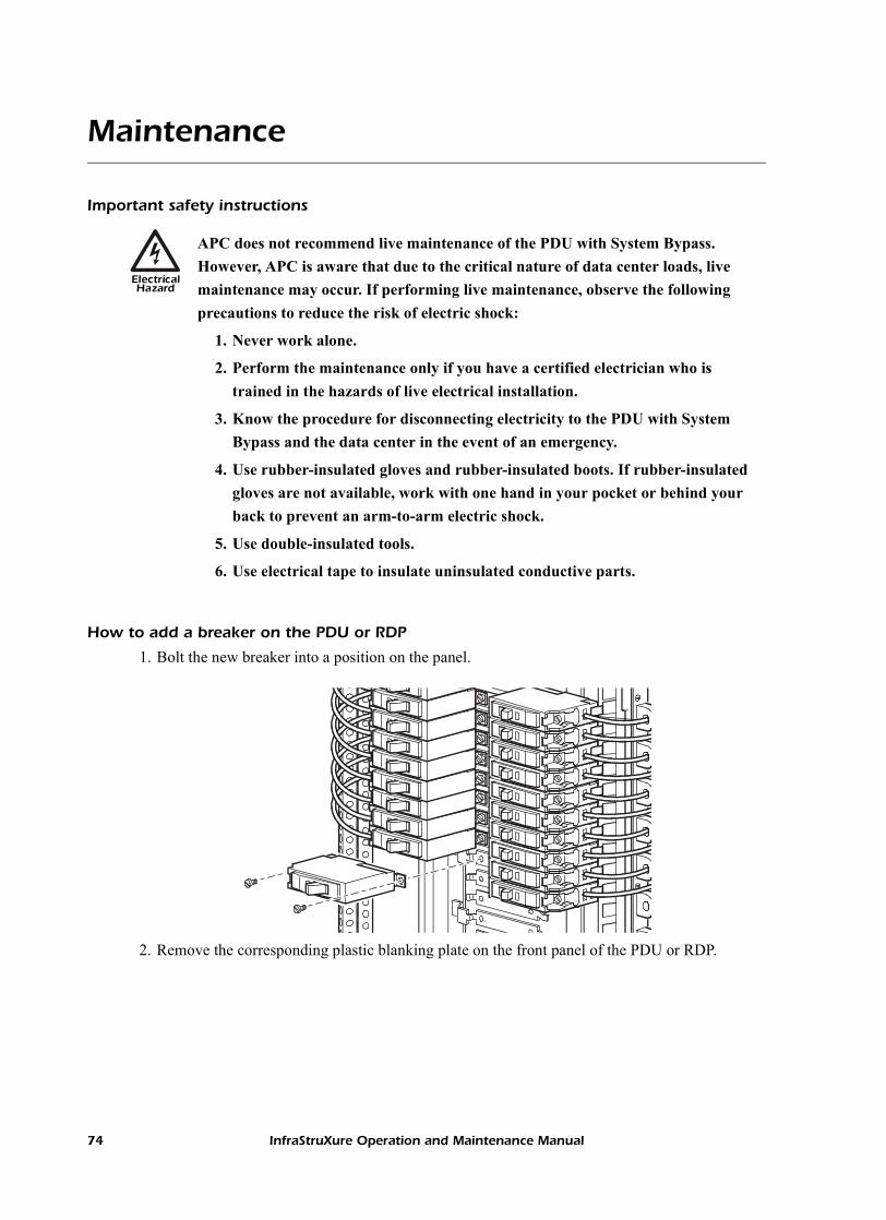
Maintenance
Important safety instructions
How to add a breaker on the PDU or RDP
1. Bolt the new breaker into a position on the panel.
2. Remove the corresponding plastic blanking plate on the front panel of the PDU or RDP.
ElectricalHazard
APC does not recommend live maintenance of the PDU with System Bypass. However, APC is aware that due to the critical nature of data center loads, live maintenance may occur. If performing live maintenance, observe the following precautions to reduce the risk of electric shock:
1. Never work alone.
2. Perform the maintenance only if you have a certified electrician who is trained in the hazards of live electrical installation.
3. Know the procedure for disconnecting electricity to the PDU with System Bypass and the data center in the event of an emergency.
4. Use rubber-insulated gloves and rubber-insulated boots. If rubber-insulated gloves are not available, work with one hand in your pocket or behind your back to prevent an arm-to-arm electric shock.
5. Use double-insulated tools.
6. Use electrical tape to insulate uninsulated conductive parts.
74 InfraStruXure Operation and Maintenance Manual

PDU with System Bypass and RDP—Maintenance
How to add a power cord to the PDU or RDP
Before adding a power cord, add a breaker.
1. Install a strain-relief connector in any available knockout on the roof of the PDU or RDP.
2. Slide enough of the power cord through the strain-relief connector to reach the new circuit breaker.
3. Tighten the strain-relief connector.
4. At the front of the PDU, connect the power cord’s individual wires:
a. If you have branch current monitoring installed, route the L1, L2, and L3 wires through a current sensor.
b. Connect the L1, L2, and L3 wires to the circuit breaker(s). The illustration below shows single pole breakers; however, you can also connect three-pole breakers.
c. Connect the neutral wire to any open termination point on the Neutral Bar that is closest to the new circuit breaker.
d. Connect the ground wire to any open termination point on the Ground Bar that is closest to the new circuit breaker.
G
N
InfraStruXure Operation and Maintenance Manual 75

Specifications
Electrical
208VAC 480VAC 600VAC
Service Distribution Breaker (provided by customer)*
200 A 100 A
Conductors to Main Input Breaker (provided by customer)*
3W + G 4W + G 4W + G
Transformer Type Isolation Step-Down Step-Down
Transformer Configuration Delta to WYE
Nominal System Input Voltage 208V Delta 480V Delta 600V Delta
Maximum System Output Voltage
280: 105V WYE 280: 105V WYE
Frequency 57 – 63 Hz
Input Voltage AC 3-phase, 3-wire plus ground
3-phase, 3-wire plus ground, and grounding electrode conductor to building steel
Output Voltage AC 3-phase 4-wire plus ground
Full Load Output Rating 80 kW 80 kW 80 kW
Maximum Continuous Input Current (at minimum mains)
155A 77A
Maximum Continuous Output Current + 125% Overload (Bypass Mode only)
168A 168A
Nominal Output Current 134A 134A
Nominal Input Current 125A 62A
Internal Static Switch Fuses 175A 175A
External Output Breaker 150A 150A
* Consult local codes for sizing requirements.
Physical
Dimensions (W×D×H) 59.7× 87.1×205.8cm
Weight 850kg
Heat Output 4521BTU
Color Black
Environmental
76 InfraStruXure Operation and Maintenance Manual

PDU with System Bypass and RDP—Specifications
Operating Environment Protected from water and conductive contaminates
Temperature Class Class H (220° C)
Storage Elevation (for aircraft transportation)
10 000 m
Relative Humidity (for operating and storage)
95% non-condensing
Operating Temperature 0 – 40° C
Acoustic Noise Emission <=50dBA
InfraStruXure Operation and Maintenance Manual 77

Product Information
Warranty
InfraStruXureTM Standard Warranty
The InfraStruXureTM system ships with a 2-year standard warranty. If you purchase all components in the InfraStruXureTM system, APC offers an additional free* 1-year warranty. Under this warranty, APC will ship all parts to your site at no cost to be available to you the next business day after APC is notified of the requirement. If you choose to upgrade the system to include an on-site contract, APC offers modular service packages to match your needs.
*All warranties are null and void unless installation and startup are performed by authorized APC Global Services service centers.
InfraStruXure Operation and Maintenance Manual 79

Service Packages
1-Day On-Site Training Service
Learn from knowledgeable professionals about topics ranging from power quality to
infrastructure cooling practices. APC training professionals have several years of experience in the infrastructure consulting industry. This service sends an APC training professional to your site to instruct your company on any of the following topics:
• Understanding UPS topologies• Trends in data center design• Concerns and issues about cooling • Measuring availability • Other related infrastructure availability topics• Servicing your Symmetra Symmetra PX UPS• Servicing your PSX Solution• Theory of operation• Understanding top problems in power quality
Other topics may be taught, if the designated professional possesses the necessary expertise.
Benefits of this service:• An APC Engineer will be on-site for one day (8 hours) to perform technical training.• Documentation for all personnel attending the training session.• For an additional fee, APC will teach you how to service the system yourself.
1-Year on-site service—InfraStruXure Type B
Quick, on-site support for critical environments. This service is a 1-year, on-site repair service on APC InfraStruXure systems and includes 7×24 (24 hours a day, 7 days a week) telephone technical support. The on-site service contract includes parts, internal batteries (if applicable), labor, and travel. This service is available with four different options that allow you to determine how quickly APC service personnel should arrive on-site for an unscheduled visit or an emergency situation:
Part numbers Service Provided
WTRAINING 1 day (8 hours) On-Site Service Training
80 InfraStruXure Operation and Maintenance Manual

Product Information—Service Packages
1-Year Next Business Day On-Site Service– APC will provide authorized personnel on-site next business day.
– The service request must be placed within defined local business hours.
1-Year Next Day On-Site Service– APC will provide authorized personnel on-site the next day, including weekends and
holidays. – The service request must be placed within defined local business hours.
1-Year 4-Hour Response On-Site Service– For environments that require immediate response. – APC will provide authorized personnel on-site within four hours of the time that APC
Technical Support deems an on-site visit is necessary. – This response level includes nights, weekends and holidays.
Benefits of this service:• Resources are freed to concentrate on core business focus.• Level of on-site response time is determined according to customer needs and desired level of
availability.• Quick response in an emergency situation.• Maximum flexibility for designing a service contract that exactly meets your needs.
Options to consider• Purchase one On-Site Service contract for every InfraStruXure Solution• Purchase the contract before expiration of your system’s factory warranty.• Combine this service with any other service offered by APC for enhanced availability (e.g.
Preventative Maintenance Visits).
Note
The next business day is defined as the next day of normal business hours.
Note
Not available in all locations. Please check with your local APC office for availability.
Note
This service is not available in all locations. Please consult http://www.apcc.com/support/service/geomap_world.cfm for coverage in your area.
InfraStruXure Operation and Maintenance Manual 81

Product Information—Service Packages
Service Packages
Note
Can be purchased only if the APC Start-Up Service has been purchased
Part numbers Coverage
WONSITENBD-PX-20 1-Year Next Business Day On-Site Service for 1–5 NetShelter enclosures
WONSITENBD-PX-21 1-Year Next Business Day On-Site Service for 1 SY(XX)K40F
WONSITENBD-PX-22 1-Year Next Business Day On-Site Service for 1 PSX PDU
WONSITENBD-PX-23 1-Year Next Business Day On-Site Service for 1 XR Battery Shelf (contains 4 SYBTU1)
WONSITEND-PX-20 1-Year Next Day On-Site Service for 1–5 NetShelter enclosures
WONSITEND-PX-21 1-Year Next Day On-Site Service for 1 SY(XX)K40F
WONSITEND-PX-22 1-Year Next Day On-Site Service for 1 PSX PDU
WONSITEND-PX-23 1-Year Next Day On-Site Service for 1 XR Battery Shelf (contains 4 SYBTU1)
WONSITE4HR-PX-20 1-Year 4-Hour Response On-Site Service for 1-5 NetShelter enclosures
WONSITE4HR-PX-21 1-Year 4-Hour Response On-Site Service for 1 SY(XX)K40F
WONSITE4HR-PX-22 1-Year 4-Hour Response On-Site Service for 1 PSX PDU
WONSITE4HR-PX-23 1-Year 4-Hour Response On-Site Service for 1 XR Battery Shelf (contains 4 SYBTU1)
82 InfraStruXure Operation and Maintenance Manual

Product Information—Service Packages
Remote Monitoring Service—InfraStruXure Type B
Increase the availability of your critical applications with 24 hour, 7 day a week
monitoring. APC’s Remote Monitoring Service is a complete, customized solution that monitors your power-protection equipment 24 hours a day, 7 days a week. The Remote Monitoring System monitors all internal parameters as well as ambient room temperature and humidity levels where the UPS is located. When a power event occurs, the monitoring equipment sends a notification to the APC Monitoring Operations Center. The event is immediately analyzed and the appropriate response is carried out according to the pre-defined customer profile.This service includes:
• Regular UPS parameter and event reports with event frequency, duration, and resolution.• Monthly alarm reports identifying actions and trends.• A customer-defined response procedure for all events through web-based applications.• In-band remote monitoring performs completely over the network via the APC Network
Management Card.
Benefits of this service:• Peace of mind about power-protection equipment• Staff/headcount reduction by outsourcing power/environmental management• Immediate notification of events by phone, paging, or E-mail• Immediate response to events to assure faster resolution of power problems• Maximum availability of network equipment, as the remote monitoring system detects potential
failures even before they occur• Increased lifetime of UPS, batteries, and other supporting equipment through the monitoring of
both internal and external critical parameters
Network integration service —all product lines
Integration of APC software and software accessories for optimal UPS management:
The APC Network Integration Service is offered for software integration into your Network Building Management System. Under this service, APC authorized personnel perform an on-site installation and integration of APC software and software accessories. This service is performed for one day (8 hours) during normal business hours. The following tasks are performed under this service:
Note
No extra equipment or installation required.
Note
All InfraStruXure™ systems ship with free access to the APC Remote Monitoring Service for six months.
Allow for a two week lead time in scheduling service.
To prepare for this service, you must define response criteria to create a tailored customer profile.
InfraStruXure Operation and Maintenance Manual 83
Product Information—Service Packages
Product preparation– Unpack, inventory, and attach all APC-required cables– Label UPS and APC accessories at your request– Mount all rack-mount APC products
Installation– Install APC software and software accessories on systems defined in the service contract.
Configuration– Configure APC software and software accessories at your request.
Integration– Configure an IP address and network settings.– Change accessory and software passwords at your request.– Route all APC and network cabling attached to APC products.
Verification of equipment– Perform a self test that applies power to the system.– Validate UPS and accessory operation.– Ping APC-networked products.– Perform a functional test at your request. (Scheduled downtime might be required.)
Benefits of this service:• Freeing of resources freed to concentrate on core business focus.• Easy installation of APC software and software accessories• Optimal integration and management of UPS systems
The APC Engineer will need the following:– Access to network systems (or a representative who has access).– Access to systems for software installation, to network connections, and to UPS devices.– Information on non-standard applications installed on workstations or servers prior to the site
visit.– A raceway or routing path for APC network cabling.– The APC Network Integration On-Site Authorization Form.
Service Package
Note
To prepare for this service you will need to have the UPS installed and APC will need to ensure that it is operational.
Part Number Services Provided
WITG Network Integration: One APC-authorized Network Integration Engineer on-site for one day
84 InfraStruXure Operation and Maintenance Manual

Product Information—Service Packages
Preventative Maintenance Visit—InfraStruXure Type B
Maximize system availability through preventative maintenance. An APC Engineer evaluates the current state of the InfraStruXure Solution, and makes recommendations to ensure the integrity of the system. During the preventative maintenance visit the engineer will do the following:
• Verify that system environment is within specified conditions• Verify proper airflow of fans• Check the system event log for any alarms and record the log.• Check all power terminals while it is supporting the equipment load.• Check all remaining terminations not previously checked.• Check the temperature of a sampling of the terminals of internal and external batteries• Verify actual voltage and current to the UPS display• Perform a discharge test• Verify proper transfer to battery operation• Test internal static bypass• Clean all dust and debris from the system• Inspect the capacitor banks for damage (if applicable)• Check that all control wires and power wires inside the system are properly seated and
undamaged• Check proper torque of power connections inside system• Visual inspection of external battery systems, if applicable
The Preventative Maintenance Visit from APC is available in two configurations:• 5 × 8: The visit will be performed within normal business hours. (8 hours per day, 5 days per
week)• 7 × 24: The visit can be performed outside normal business hours, including weekends and
holidays. (24 hours per day, 7 days per week)
Benefits of this service:• Maximize system availability through preventative maintenance.• Assure that the system will be performing according to specifications.• Ensure that unplanned outages of critical systems do not occur.• Receive full status of all on-site activities.• Optimize the lifetime of system
InfraStruXure Operation and Maintenance Manual 85

Product Information—Service Packages
Service Packages
Note
• Does not include parts.• Includes labor and travel expenses.• Allow for a two-week lead time when scheduling service.• Can be ordered as a stand-alone visit or with any service contract from APC.
Additional visits can be purchased for the same system, if more than one visit a year is required.
• Contact your local APC office for information about its normal business hours.
Part numbers Coverage
WPMV5X8-PX-20 Maintenance Visit for 1–5 Netshelter enclosures performed within normal business hours
WPMV5X8-PX-21 Maintenance Visit for 1 SY(XX)K40F performed within normal business hours
WPMV5X8-PX-22 Maintenance Visit for 1 PSX PDU performed within normal business hours
WPMV5X8-PX-23 Maintenance Visit for 1 XR Battery Shelf (contains 4 SYBTU1) performed within normal business hours
WPMV7X24-PX-20 Maintenance Visit for 1–5 Netshelter enclosures performed at any time, including weekends and holidays
WPMV7X24-PX-21 Maintenance Visit for 1 SY(XX)K40F Netshelter enclosure performed at any time, including weekends and holidays
WPMV5X8-PX-22 Maintenance Visit for 1 PSX PDU performed within normal business hours
WPMV7X24-PX-23 Maintenance Visit for 1 XR Battery Shelf (contains 4 SYBTU1) performed at any time, including weekends and holidays
86 InfraStruXure Operation and Maintenance Manual

Product Information—Service Packages
Start-Up Service—InfraStruXure Type B
Ensure proper Start-Up and functionality of InfraStruXure™ system. APC’s Start-Up Service provides customers with APC Authorized Personnel to ensure proper Start-Up of the InfraStruXure™ system. APC will do all the internal wiring of the system, and check that it is functioning properly in all modes to ensure compliance with stated technical specifications. The Field Service Engineer will position and configure the entire solution as specified by the customer on the Configure To Order (C.T.O) report. Working closely with the electrician on site, the Field Service Engineer will then put the system into operation after the electrician has connected the input wires to the system.
APC will guarantee that the system is operating according to APC standards as follows:• Perform visual inspection of InfraStruXure equipment to ensure that all connections are
correctly and securely attached.• Verify the following:
– That wiring is correct, noting any discrepancies.– That all power wires are terminated in the correct location on the InfraStruXure system.– That all internal functions are operating according to the specifications for a InfraStruXure
system.– That all electrical wiring on the InfraStruXure system complies with all local and national
electrical codes and regulations.– That all bypass functions, static and manual, are operating properly– That all APC components are installed properly.
• Record all front panel reading and parameter stacks.• Clean the system.• Start the InfraStruXure system and perform a comprehensive diagnostic and self-test
As part of a Start-Up package included with the InfraStruXure™ system, the APC trained technician will spend 1 hour training the client on the functioning of the system.
The Start-Up Service is available in two options:• Start-Up Service performed within normal business hours. (8 hours per day, 5 days per week)• Start-Up Service performed outside normal business hours, including weekends and holidays.
(24 hours per day, 7 days per week)
Benefits of this service:• Proper installation and internal wiring.• A InfraStruXure system performing to specifications by the end of the service.• Support staff trained on proper use of the system.
InfraStruXure Operation and Maintenance Manual 87

Product Information—Service Packages
Note
• Customer must purchase one contract per InfraStruXure system.• Separate contracts must be purchased for external batteries. • Allow for a two-week lead time in scheduling service.• The customer’s electrician must be present to connect wires from the service panel
to the Power Distribution Unit.
Part numbers Coverage
WSTRTUP5X8-PX-20 Start-up of 1-5 Netshelter enclosures performed within normal business hours
WSTRTUP5X8-PX-21 Start-up of 1 SY(XX)K40F performed within normal business hours
WSTRTUP5X8-PX-22 Start-up of 1 PSX PDU performed within normal business hours
WSTRTUP5X8-PX-23 Start-up of 1 XR Battery Shelf (contains 4 SYBTU1) performed within normal business hours
WSTRTUP7X24-PX-20 Start-up of 1-5 Netshelter enclosures performed at any hour including weekends and holidays
WSTRTUP7X24-PX-21 Start-up of 1 SY(XX)K40F performed at any hour including weekends and holidays
WSTRTUP7X24-PX-22 Start-up of 1 PSX PDU performed at any hour including weekends and holidays
WSTRTUP7X24-PX-23 Start-up of 1 XR Battery Shelf (contains 4 SYBTU1) performed at any hour including weekends and holidays
88 InfraStruXure Operation and Maintenance Manual

Product Information—Life-Support Policy
Life-Support Policy
APC Three-Phase Systems
American Power Conversion Corporation (APC) and its affiliates and subsidiaries world-wide do not recommend the use of any of their products in life support applications where failure or malfunction of the APC product can be reasonably expected to cause failure of the life support device or to significantly affect its safety or effectiveness. APC does not permit the use of any of its products in direct patient care. APC will not knowingly sell its products for use in such applications unless the life support system or direct patient care device is part of a whole facility/building into which the UPS is integrated and unless APC receives in writing assurances satisfactory to APC that all of the following are true:
• the UPS system will be configured in a manner that will provide N+1 power redundancy to the critical load
• the end-user customer assumes all risks and signs the APC System Configuration and Use Form, and
• the customer and operators of the APC UPS system agree to indemnify and hold APC and its affiliates and subsidiaries harmless for any and all claims arising out of the systems used in such applications.
The term life-support device includes but is not limited to neonatal oxygen analyzers, nerve stimulators (whether used for anesthesia, pain relief, or other purposes), autotransfusion devices, blood pumps, defibrillators, arrhythmia detectors and alarms, pacemakers, hemodialysis systems, peritoneal dialysis systems, neonatal ventilator incubators, ventilators (for adults and infants), anesthesia ventilators, infusion pumps, and any other devices designated as “critical” by the U.S. FDA.
Hospital-grade wiring devices and leakage current protection may be ordered as options on many APC UPS systems. APC does not claim that units with these modifications are certified or listed as hospital-grade by APC or any other organization. Therefore these units do not meet the requirements for use in direct patient care.
InfraStruXure Operation and Maintenance Manual 89

How to Contact APC
APC Worldwide Customer Support
Customer support for this or any other APC product is available at no charge in any of the following ways:
• Visit the APC Web site to find answers to frequently asked questions (FAQs), to access documents in the APC Knowledge Base, and to submit customer support requests.– www.apc.com (Corporate Headquarters)– Connect to localized APC Web sites for specific countries, each of which provides customer
support information.– www.apc.com/support/– Global support with FAQs, knowledge base, and e-support.– Contact an APC Customer Support center by telephone or e-mail.– Regional centers:
.
– Local, country-specific centers: go to www.apc.com/support/contact for contact information.• Contact the APC representative or other distributor from whom you purchased your APC
product for information on how to obtain local customer support.
APC Corporate Headquarters (U.S. and Canada)
877-537-0607 (toll-free)
Latin America (1) (401) 789-5735 (United States)
Europe, Middle East, Africa (353) (91) 702020 (Ireland)
Japan (03) 5434-2021
90 InfraStruXure Operation and Maintenance Manual

How to Obtain Service
Obtaining service
To obtain support for problems with your PowerStruXure System:0
1. Note the serial number and date of purchase. of the component with which you are having problems.
2. Contact Customer Support at a phone number on the back cover of this document. A technician will try to help you solve the problem by phone.
3. If you must return the product, the technician will give you a return material authorization (RMA) number. If the warranty expired, you will be charged for repair or replacement.
4. Pack the unit carefully. The warranty does not cover damage sustained in transit. Enclose a letter with your name, address, RMA number and daytime phone number; a copy of the sales receipt; and a check as payment, if applicable.
5. Mark the RMA number clearly on the outside of the shipping carton.
6. Ship by insured, prepaid carrier to the address provided by the Customer Support technician.
Note
If you ordered on-site service, see your entitlement certificate and terms and conditions of the service before following the procedure described below. An on-site service contract entitles you to an on-site visit by an APC technician to assess the issue, determine the problem, and replace parts, if needed. (Response time varies per contract.)
InfraStruXure Operation and Maintenance Manual 91


a

APC Worldwide Customer Support
Customer support for this or any other APC product is available at no charge in any of the following ways:• Visit the APC Web site to find answers to frequently asked questions (FAQs), to access documents
in the APC Knowledge Base, and to submit customer support requests.– www.apc.com (Corporate Headquarters)
Connect to localized APC Web sites for specific countries, each of which provides customer support information.
– www.apc.com/support/Global support with FAQs, knowledge base, and e-support.
• Contact an APC Customer Support center by telephone or e-mail.– Regional centers:
– Local, country-specific centers: go to www.apc.com/support/contact for contact information.
Contact the APC representative or other distributor from whom you purchased your APC product for information on how to obtain local customer support.
APC headquarters U.S., Canada (1)(800)800-4272 (toll free)
Latin America (1)(401)789-5735 (USA)
Europe, Middle East, Africa (353)(91)702020 (Ireland)
Japan (0) 35434-2021
Entire contents copyright © 2003 American Power Conversion. All rights reserved. Reproduction in whole or in part without permission is prohibited. APC, the APC logo,
NetShelter, Symmetra and InfraStruXure are trademarks of American Power Conversion Corporation and may be registered in some jurisdictions. All other trademarks, product names, and corporate names are the property of their respective owners and are used for
informational purposes only.
990-1468 05/2003