infrastructure-as-a-service product line architecture€¦ · web viewinfrastructure-as-a-service...
TRANSCRIPT

Fabric Architecture Guide
9-May-23Version 2.0
Ryan Bergau (Ally Inc)
Infrastructure-as-a-Service Product Line Architecture

IaaS PLA Fabric Guide
iiInfrastructure-as-a-Service Product Line Architecture, Version 2.0 “Infrastructure-as-a-Service Architecture" last modified on 4 Dec. 13

IaaS PLA Fabric Guide
Revision and Signoff Sheet
Change RecordDate Author Version Change Reference
10/28/2012
Microsoft Services 1.0 Initial Release Version
11/19/2012
Microsoft Services 1.1 Service Provider and Partner Revision
11/18/2013
Microsoft Services 2.0 Windows Server 2012 R2 Release
ReviewersName Version Approved Position Date
Infrastructure-as-a-Service Product Line Architecture, Version 2.0 Prepared by Microsoft“Infrastructure-as-a-Service Architecture" last modified on

IaaS PLA Fabric Guide
Table of Contents
1 Introduction.............................................................................................101.1 Scope......................................................................................................................101.2 Microsoft Private Cloud Fast Track..........................................................................101.3 Microsoft Services...................................................................................................11
2 IaaS Product Line Architecture Overview.................................................122.1 IaaS Reference Architectures..................................................................................12
2.1.1 Product Line Architecture Fabric Design Patterns.....................................132.2 Product Line Architecture Rule Sets........................................................................15
2.2.1 Rule Set Criteria............................................................................................162.2.2 Windows Hardware Certification..................................................................162.2.3 Windows Licensing........................................................................................18
3 Software-Defined Infrastructure..............................................................204 Non-Converged Infrastructure Pattern Overview.....................................245 Converged Infrastructure Pattern Overview............................................276 Hybrid Infrastructure Pattern...................................................................297 Storage Architecture................................................................................31
7.1 Disk Architectures...................................................................................................317.1.1 Serial ATA (SATA)..........................................................................................317.1.2 SAS..................................................................................................................327.1.3 Nearline SAS (NL-SAS)..................................................................................347.1.4 Fibre Channel.................................................................................................357.1.5 Solid-State Storage.......................................................................................367.1.6 Hybrid Drives.................................................................................................377.1.7 Advanced Format (4K) Disk Compatibility..................................................37
7.2 Storage Controller Architectures.............................................................................397.2.1 SATA III...........................................................................................................407.2.2 PCIe/SAS HBA.................................................................................................417.2.3 PCIe RAID/Clustered RAID.............................................................................427.2.4 Fibre Channel HBA.........................................................................................44
7.3 Storage Networking.................................................................................................45
Infrastructure-as-a-Service Product Line Architecture, Version 2.0 Prepared by Microsoft“Infrastructure-as-a-Service Architecture" last modified on

IaaS PLA Fabric Guide
7.3.1 Fibre Channel.................................................................................................457.3.2 iSCSI................................................................................................................467.3.3 Fibre Channel over Ethernet (FCoE)............................................................487.3.4 InfiniBand.......................................................................................................497.3.5 Switched SAS.................................................................................................507.3.6 Network File System (NFS)...........................................................................517.3.7 SMB 3.0...........................................................................................................52
7.4 Windows File Services.............................................................................................667.4.1 Storage Spaces..............................................................................................667.4.2 Resilient File System (ReFS)........................................................................737.4.3 NTFS Improvements......................................................................................747.4.4 Scale-Out File Server Cluster Architecture.................................................76
7.5 Storage Features.....................................................................................................787.5.1 Data Deduplication........................................................................................787.5.2 Thin Provisioning and Trim...........................................................................807.5.3 Volume Cloning..............................................................................................817.5.4 Volume Snapshot...........................................................................................827.5.5 Storage Tiering..............................................................................................82
7.6 Storage Management and Automation....................................................................837.6.1 ODX.................................................................................................................84
8 Network Architecture...............................................................................878.1 Network Architecture Patterns.................................................................................87
8.1.1 Hierarchical....................................................................................................878.1.2 Flat Network...................................................................................................898.1.3 Network Virtualization (Software-Defined Networking)............................89
8.2 Network Performance and Low Latency..................................................................908.2.1 Data Center Bridging....................................................................................908.2.2 Virtual Machine Queue (VMQ)......................................................................918.2.3 IPsec Task Offload..........................................................................................928.2.4 Quality of Service (QoS)...............................................................................938.2.5 Remote Direct Memory Access....................................................................948.2.6 Receive Segment Coalescing.......................................................................968.2.7 Receive-Side Scaling.....................................................................................968.2.8 SR-IOV.............................................................................................................988.2.9 TCP Chimney Offload.....................................................................................99
Infrastructure-as-a-Service Product Line Architecture, Version 2.0 Prepared by Microsoft“Infrastructure-as-a-Service Architecture" last modified on
IaaS PLA Fabric Guide
8.3 Network High Availability and Resiliency.................................................................998.3.1 NIC Teaming.................................................................................................100
8.4 Network Isolation and Security..............................................................................1068.4.1 VLANs............................................................................................................1068.4.2 Trunk Mode to Virtual Machines................................................................1078.4.3 Private VLANs...............................................................................................1078.4.4 ARP and Neighbor Discovery Spoofing Protection...................................1098.4.5 Router Guard................................................................................................1098.4.6 DHCP Guard..................................................................................................1108.4.7 Virtual Port ACLs..........................................................................................1118.4.8 Network Virtualization................................................................................113
9 Compute Architecture............................................................................1179.1 Server Architecture...............................................................................................117
9.1.1 Server and Blade Network Connectivity...................................................1189.1.2 Microsoft Multipath I/O...............................................................................1199.1.3 Consistent Device Naming.........................................................................120
9.2 Failover Clustering.................................................................................................1219.2.1 Cluster-Aware Updating..............................................................................1219.2.2 Cluster Shared Volumes.............................................................................123
9.3 Hyper-V Failover Clustering...................................................................................1309.3.1 Host Failover-Cluster Topology..................................................................1309.3.2 Cluster Quorum and Witness Configurations...........................................1319.3.3 Host Cluster Networks................................................................................1339.3.4 Hyper-V Application Monitoring.................................................................1369.3.5 Virtual Machine Failover Prioritization......................................................1379.3.6 Virtual Machine Anti-Affinity......................................................................1399.3.7 Virtual Machine Drain on Shutdown..........................................................1399.3.8 Shared Virtual Hard Disk............................................................................140
10 Hyper-V Virtualization Architecture.......................................................14210.1 Hyper-V Features...................................................................................................142
10.1.1 Hyper-V Host and Guest Scale-Up.............................................................14210.1.2 Hyper-V over SMB 3.0.................................................................................14210.1.3 Virtual Machine Mobility.............................................................................14310.1.4 Storage Migration........................................................................................147
Infrastructure-as-a-Service Product Line Architecture, Version 2.0 Prepared by Microsoft“Infrastructure-as-a-Service Architecture" last modified on

IaaS PLA Fabric Guide
10.1.5 Hyper-V Extensible Switch.........................................................................14810.1.6 Virtual Fibre Channel..................................................................................15410.1.7 VHDX.............................................................................................................15710.1.8 Guest Non-Uniform Memory Access..........................................................15810.1.9 Dynamic Memory.........................................................................................15910.1.10 Hyper-V Replica........................................................................................16010.1.11 Resource Metering...................................................................................16110.1.12 Enhanced Session Mode..........................................................................163
10.2 Hyper-V Guest Virtual Machine Design..................................................................16510.2.1 Virtual Machine Storage.............................................................................16610.2.2 Virtual Machine Networking.......................................................................16810.2.3 Virtual Machine Compute...........................................................................16910.2.4 Linux-Based Virtual Machines....................................................................17210.2.5 Automatic Virtual Machine Activation.......................................................173
11 Windows Azure IaaS Architecture..........................................................17611.1 Windows Azure Services........................................................................................177
11.1.1 Windows Azure Compute Services............................................................17711.1.2 Windows Azure Data Services....................................................................17711.1.3 Windows Azure Network Services..............................................................17811.1.4 Windows Azure Application Services.........................................................178
11.2 Windows Azure Accounts and Subscriptions..........................................................17911.2.1 Sharing Service Management by Adding Co-Administrators..................18011.2.2 Manage Storage Accounts for Your Subscription.....................................18111.2.3 Create Affinity Groups to Use with Storage Accounts and Hosted Services
18111.2.4 Add Management Certificates to a Windows Azure Subscription..........18211.2.5 Creating and Managing Windows Azure Environments...........................182
11.3 Windows Azure Service-Level Agreements (SLAs).................................................18411.3.1 Caching.........................................................................................................18411.3.2 CDN...............................................................................................................18411.3.3 Cloud Services, Virtual Machines and Virtual Network...........................18411.3.4 Media Services.............................................................................................18411.3.5 Mobile Services............................................................................................18511.3.6 Multi-Factor Authentication........................................................................18511.3.7 Service Bus..................................................................................................185
Infrastructure-as-a-Service Product Line Architecture, Version 2.0 Prepared by Microsoft“Infrastructure-as-a-Service Architecture" last modified on

IaaS PLA Fabric Guide
11.3.8 SQL Database...............................................................................................18511.3.9 SQL Reporting..............................................................................................18611.3.10 Storage......................................................................................................18611.3.11 Web Sites..................................................................................................186
11.4 Windows Azure Pricing..........................................................................................18611.5 Extending the Datacenter Fabric to Windows Azure..............................................187
11.5.1 Storage—Windows Azure Storage.............................................................18711.5.2 Compute – Windows Azure IaaS.................................................................19911.5.3 Network - Windows Azure Networking......................................................213
12 Fabric and Fabric Management..............................................................22412.1 Fabric....................................................................................................................22412.2 Fabric Management...............................................................................................225
12.2.1 Fabric Management Host Architecture.....................................................225
13 Non-Converged Architecture Pattern.....................................................22713.1 Compute................................................................................................................228
13.1.1 Hyper-V Host Infrastructure.......................................................................22813.2 Network.................................................................................................................230
13.2.1 Host Connectivity........................................................................................23113.3 Storage..................................................................................................................233
13.3.1 Storage Connectivity...................................................................................23413.3.2 Storage Infrastructure................................................................................235
14 Converged Architecture Pattern............................................................23814.1 Compute................................................................................................................239
14.1.1 Hyper-V Host Infrastructure.......................................................................23914.2 Network.................................................................................................................240
14.2.1 Host Connectivity........................................................................................24114.3 Storage..................................................................................................................242
14.3.1 Storage Connectivity...................................................................................24314.3.2 Storage Infrastructure................................................................................244
15 Software Defined Infrastructure Architecture Pattern............................24815.1 Compute................................................................................................................249
15.1.1 Hyper-V Host Infrastructure.......................................................................25015.2 Network.................................................................................................................252
15.2.1 Host Connectivity........................................................................................253
Infrastructure-as-a-Service Product Line Architecture, Version 2.0 Prepared by Microsoft“Infrastructure-as-a-Service Architecture" last modified on

IaaS PLA Fabric Guide
15.3 Storage..................................................................................................................25415.3.1 Storage Connectivity...................................................................................25415.3.2 Scale-Out File Server Cluster Architecture...............................................25515.3.3 Storage Infrastructure................................................................................260
16 Multi-Tenant Designs.............................................................................26316.1 Requirements Gathering.......................................................................................26316.2 Infrastructure Requirements..................................................................................26416.3 Multi-Tenant Storage Considerations.....................................................................265
16.3.1 SMB 3.0.........................................................................................................26516.4 Multi-Tenant Network Considerations....................................................................268
16.4.1 Windows Network Virtualization................................................................26816.4.2 Hyper-V Extensible Switch.........................................................................27116.4.3 Example Network Design............................................................................272
16.5 Multi-Tenant Compute Considerations...................................................................27416.5.1 Hyper-V.........................................................................................................27516.5.2 Failover Clustering......................................................................................27616.5.3 Resource Metering......................................................................................27616.5.4 Management................................................................................................276
Infrastructure-as-a-Service Product Line Architecture, Version 2.0 Prepared by Microsoft“Infrastructure-as-a-Service Architecture" last modified on

IaaS PLA Fabric Guide – Microsoft Confidential
1 IntroductionThe goal of the Infrastructure-as-a-Service (IaaS) product line architecture (PLA) is to help organizations develop and implement private cloud infrastructures quickly while reducing complexity and risk. The IaaS PLA provides a reference architecture that combines Microsoft software, consolidated guidance, and validated configurations with partner technology such as compute, network, and storage architectures, in addition to value-added software components.The private cloud model provides much of the efficiency and agility of cloud computing, with the increased control and customization that are achieved through dedicated private resources. By implementing private cloud configurations that align to the IaaS PLA, Microsoft and its hardware partners can help provide organizations the control and the flexibility that are required to reap the potential benefits of the private cloud.The IaaS PLA utilizes the core capabilities of the Windows Server operating system, Hyper-V, and System Center to deliver a private cloud infrastructure as a service offering. These are also key software components that are used for every reference implementation.
1.1 ScopeThe scope of this document is to provide customers with the necessary guidance to develop solutions for a Microsoft private cloud infrastructure in accordance with the IaaS PLA patterns that are identified for use with the Windows Server 2012 R2 operating system. This document provides specific guidance for developing fabric architectures (compute, network, storage, and virtualization layers) of an overall private cloud solution. Accompanying guidance is provided in the following guide for the development of an accompanying fabric management architecture that uses System Center 2012 R2.
1.2 Microsoft Private Cloud Fast TrackThe Microsoft Private Cloud Fast Track is a joint effort between Microsoft and its hardware partners to deliver preconfigured virtualization and private cloud solutions. The Private Cloud Fast Track focuses on the new technologies and services in Windows Server in addition to investments in System Center. The validated designs in the Private Cloud Fast Track are delivering a “best-of-breed solution” from our hardware partners that drive Microsoft technologies,
Page Infrastructure-as-a-Service Product Line Architecture, Version 2.0 Prepared by Microsoft“Infrastructure-as-a-Service Architecture" last modified on
IaaS PLA Fabric Guide
investments, and best practices. The Private Cloud Fast Track has expanded the footprint, and it enables a broader choice with different architectures. Market availability of the Private Cloud Fast Track validated designs from our hardware partners have been launched with Microsoft solutions. Please visit the Private Cloud Fast Track website for the most up-to-date information and validated solutions.
1.3 Microsoft ServicesMicrosoft Services is comprised of a global team of architects, engineers, consultants, and support professionals who are dedicated to helping customers maximize the value of their investment in Microsoft software. Microsoft Services touches customers in over 82 countries, helping them plan, deploy, support, and optimize Microsoft technologies. Microsoft Services works closely with Microsoft Partners by sharing their technological expertise, solutions, and product knowledge. For more information about the solutions that Microsoft Services offers or to learn about how to engage with Microsoft Services and Partners, please visit the Microsoft Services website.
Page 11Infrastructure-as-a-Service Product Line Architecture, Version 2.0 Prepared by Microsoft“Infrastructure-as-a-Service Architecture" last modified on 4 Dec. 13

IaaS PLA Fabric Guide
2 IaaS Product Line Architecture OverviewThe IaaS PLA is focused on deploying virtualization fabric and fabric management technologies in Windows Server and System Center to support private cloud scenarios. This PLA includes reference architectures, best practices, and processes for streamlining deployment of these platforms to support private cloud scenarios. This component of the IaaS PLA focuses on delivering core foundational virtualization fabric infrastructure guidance that aligns to the defined architectural patterns within this and other Windows Server 2012 R2 private cloud programs. The resulting Hyper-V infrastructure in Windows Server 2012 R2 can be leveraged to host advanced workloads, and subsequent releases will contain fabric management scenarios using System Center components. Scenarios relevant to this release include:
Resilient infrastructure – Maximize the availability of IT infrastructure through cost-effective redundant systems that prevent downtime, whether planned or unplanned.
Centralized IT – Create pooled resources with a highly virtualized infrastructure that supports maintaining individual tenant rights and service levels.
Consolidation and migration – Remove legacy systems and move workloads to a scalable high-performance infrastructure.
Preparation for the cloud – Create the foundational infrastructure to begin transition to a private cloud solution.
2.1 IaaS Reference ArchitecturesMicrosoft Private Cloud programs have two main solutions as shown in figure 1. This document focuses on the open solutions model to service the Enterprise and hosting provider audiences.
Figure 1 Branches of the Microsoft Private CloudEach audience should use a reference architecture that defines the requirements that are necessary to design, build, and deliver virtualization and private cloud
Page 12Infrastructure-as-a-Service Product Line Architecture, Version 2.0 Prepared by Microsoft“Infrastructure-as-a-Service Architecture" last modified on 4 Dec. 13
SMB solutionsFrom 2 to 4 hosts
Up to 75 server virtual machines
Open solutionsFrom 6 to 64 hostsUp to 8,000 server
virtual machines
IaaS PLA Fabric Guide
solutions for small and medium enterprise and hosting service provider implementations.
Page 13Infrastructure-as-a-Service Product Line Architecture, Version 2.0 Prepared by Microsoft“Infrastructure-as-a-Service Architecture" last modified on 4 Dec. 13

IaaS PLA Fabric Guide
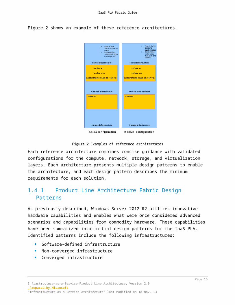
Figure 2 shows an example of these reference architectures.
Figure 2 Examples of reference architecturesEach reference architecture combines concise guidance with validated configurations for the compute, network, storage, and virtualization layers. Each architecture presents multiple design patterns to enable the architecture, and each design pattern describes the minimum requirements for each solution.
2.1.1Product Line Architecture Fabric Design PatternsAs previously described, Windows Server 2012 R2 utilizes innovative hardware capabilities and enables what were once considered advanced scenarios and capabilities from commodity hardware. These capabilities have been summarized into initial design patterns for the IaaS PLA. Identified patterns include the following infrastructures:
Software-defined infrastructure Non-converged infrastructure Converged infrastructure
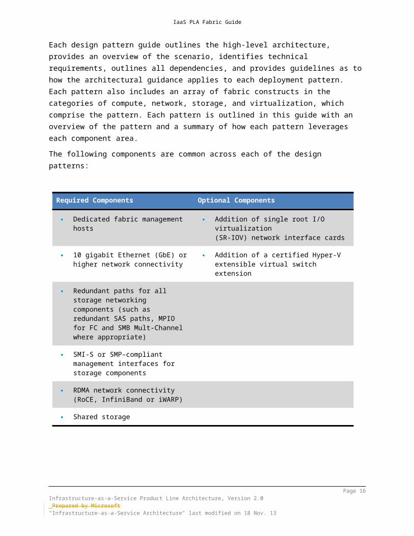
Each design pattern guide outlines the high-level architecture, provides an overview of the scenario, identifies technical requirements, outlines all dependencies, and provides guidelines as to how the architectural guidance applies to each deployment pattern. Each pattern also includes an array of fabric constructs in the categories of compute, network, storage, and virtualization, which comprise the
Page 14Infrastructure-as-a-Service Product Line Architecture, Version 2.0 Prepared by Microsoft“Infrastructure-as-a-Service Architecture" last modified on 4 Dec. 13
IaaS PLA Fabric Guide
pattern. Each pattern is outlined in this guide with an overview of the pattern and a summary of how each pattern leverages each component area.The following components are common across each of the design patterns:
Required Components Optional Components
Dedicated fabric management hosts
Addition of single root I/O virtualization
(SR-IOV) network interface cards
10 gigabit Ethernet (GbE) or higher network connectivity
Addition of a certified Hyper-V extensible virtual switch extension
Redundant paths for all storage networking components (such as redundant SAS paths, MPIO for FC and SMB Mult-Channel where appropriate)
SMI-S or SMP–compliant management interfaces for storage components
RDMA network connectivity (RoCE, InfiniBand or iWARP)
Shared storage
The following table outlines the Windows Server 2012 R2 features and technologies that are common to all patterns:
Windows Server 2012 R2 Feature Key Scenarios
Increased VP:LP ratio Removal of previous limits of 8:1 processor ratios for server workloads and 12:1 processor ratios for client workloads.
Increased virtual memory and Dynamic Memory
Supports up to 1 TB of memory inside virtual machines.
Virtual machine guest clustering enhancements
Supports virtual machine guest clusters by using a shared virtual hard disk (shared VHDX), iSCSI connections or by using the Hyper-V Fibre Channel adapter to connect virtual machines to shared storage.
Hyper-V extensible switch A virtual Ethernet switch that allows for third
Page 15Infrastructure-as-a-Service Product Line Architecture, Version 2.0 Prepared by Microsoft“Infrastructure-as-a-Service Architecture" last modified on 4 Dec. 13
IaaS PLA Fabric Guide
Windows Server 2012 R2 Feature Key Scenariosparty filtering, capturing, and forwarding of extensions that are to be added to support additional virtual-switch functionality on the Hyper-V platform.
Cluster-aware updating Provides the ability to apply updates to running failover clusters through coordinated patching of individual failover-cluster nodes.
Live Migration Enhancements Live migration supports migration of virtual machines without shared storage, compression of memory and using the SMB 3.0 protocol
Support for SR-IOV Provides the ability to assign a network adapter that supports single-root I/O virtualization (SR-IOV) directly to a virtual machine.
Support for 4K physical disks Supports native 4K disk drives on hosts.
Diskless network boot with iSCSI Software Target Provides the network-boot capability on
commodity hardware by using an iSCSI boot–capable network adapter or a software boot loader.
Virtual Machine Generation Enhancements Windows Server 2012 R2 introduces Generation 2 virtual machines which supports new functionality on virtual machines such as UEFI firmware, PXE boot and Secure Boot.
Virtual machine storage enhancements (VHDX) Supports VHDX disks that are up to 64 TB in size
and shared virtual hard disks (shared VHDX)
Windows NIC Teaming Supports switch-independent and switch-dependent load distribution by using physical and virtual network connections.
Data center bridging Provides hardware support for converged fabrics, which allows bandwidth allocation and priority flow control.
Table 1 Windows Server 2012 R2 features and key scenarios applicable to all patterns
2.2 Product Line Architecture Rule SetsThe IaaS PLA describes the minimum requirements that Microsoft will use to validate private cloud solutions that were built by using the design patterns that this document describes. These rule sets are organized into categories, according to the criteria specified in the following subsections.
Page 16Infrastructure-as-a-Service Product Line Architecture, Version 2.0 Prepared by Microsoft“Infrastructure-as-a-Service Architecture" last modified on 4 Dec. 13

IaaS PLA Fabric Guide
2.2.1Rule Set CriteriaRule set requirements are vendor-agnostic and are categorized as one of the following:
Mandatory: Mandatory best practice; vendor-agnostic solution. These requirements are necessary for alignment with the PLA.
Recommended: Recommended best practice. These requirements describe industry-standard best practices that are strongly recommended. However, implementation of these requirements is at the discretion of each customer. These requirements are not required for alignment with the PLA.
Optional: Optional best practice. These requirements are voluntary considerations that can be implemented in the solution at the discretion of each customer.
2.2.2Windows Hardware CertificationIn IaaS PLA implementations, it is mandatory that each architecture solution pass the following validation requirements:
Windows hardware certification Failover-clustering validation Clustered RAID controller validation (if a third-party clustered RAID controller
is used)Each of these rule sets are described in one of the subsections that follow.
2.2.2.1 Windows Hardware CertificationHardware solutions must receive validation through the Microsoft “Certified for Windows Server 2012 R2” program before it can be presented in the Windows Server Catalog. The catalog contains all servers, storage, and other hardware devices that are certified for use with Windows Server 2012 and Hyper-V.The Certified for Windows Server 2012 R2 logo demonstrates that a server system meets Microsoft’s highest technical bar for security, reliability, and manageability, and any required hardware components that support all of the roles, features, and interfaces that Windows Server 2012 R2 supports.
Page 17Infrastructure-as-a-Service Product Line Architecture, Version 2.0 Prepared by Microsoft“Infrastructure-as-a-Service Architecture" last modified on 4 Dec. 13

IaaS PLA Fabric Guide
The logo program and support policy for failover-clustering solutions requires that all individual components that make up a cluster configuration earn the appropriate "Certified for" or "Supported" on Windows Server 2012 R2 designations before they are listed in their device-specific categories in the Windows Server Catalog.For more information, go to the Windows Server Catalog at www.windowsservercatalog.com. Under “Hardware Testing Status”, click “Certified for Windows Server 2012 R2”. The two primary entry points are the Windows Hardware Certification (HCK) process and the Windows Dev Center Hardware and Desktop Dashboard portal for starting the logo-certification process.This validation requirement includes the following:PLA Rule Set - All Patterns
Mandatory: All solution components must be logo-certified for Windows Server 2012 R2 by Microsoft.
2.2.2.2 Failover-Clustering ValidationFor Windows Server 2012 R2, failover clustering can be validated by using the in-box Cluster Validation Tool to confirm network and shared storage connectivity between the nodes of the cluster. The tool runs a set of focused tests on the set of servers that are to be used as nodes in a cluster, or are already members of a given cluster. This failover-cluster validation process will test the underlying hardware and software directly and individually obtain an accurate assessment of whether the failover clustering has the ability to support a given configuration.Cluster validation is used to identify hardware or configuration problems before the cluster goes into production. This helps to make sure that a solution is truly dependable. In addition, cluster validation can also be performed as a diagnostic tool on configured failover clusters. Note that the failover cluster must be tested and must pass the failover-cluster validation to be able to receive end-customer support from Microsoft Customer Support Services (CSS).PLA Rule Set - All Patterns
Mandatory: A Microsoft Cluster Validation Tool report must be generated and reviewed by the customer and consultant. The tool and test description can be found at http://technet.microsoft.com/library/jj134244.aspx. Use the Validate a Configuration Wizard tool and run “All Tests”. The report should contain no “Error” messages. (Informational and Warning messages are accepted as far as they are clearly understood and represent known specifics of a given solution).
Page 18Infrastructure-as-a-Service Product Line Architecture, Version 2.0 Prepared by Microsoft“Infrastructure-as-a-Service Architecture" last modified on 4 Dec. 13

IaaS PLA Fabric Guide
2.2.2.3 Clustered RAID Controller ValidationClustered RAID controllers are a relatively new type of storage interface card that can be used with shared storage and cluster scenarios, as the RAID controllers across configured servers are able to present shared storage. In this case, the clustered RAID controller solution must pass the clustered RAID controller validation. If the solution includes a clustered RAID controller, this validation requirement includes the following:PLA Rule Set - All Patterns
Mandatory: If a clustered RAID controller will be utilized, the solution must pass the clustered RAID controller validation (Clustered RAID Controllers - Requirements and Validation Test Kit). A passing validation report should be reviewed by the OEM or customer and consultant depending on delivery.
2.2.3Windows LicensingIaaS PLA architectures use the Windows Server 2012 R2 Standard or Windows Server 2012 R2 Datacenter. For more information about the Windows Server 2012 R2 operating systems, please see Windows Server 2012 R2 on the Microsoft website.The packaging and licensing for Windows Server 2012 R2 have been updated to simplify purchasing and reduce management requirements, as shown in the following table. The Windows Server 2012 R2 Datacenter and Standard editions are differentiated only by virtualization rights—two virtual instances for the Standard edition, and an unlimited number of virtual instances for the Datacenter edition. For more information about Windows Server 2012 R2 licensing, see the Windows Server 2012 R2 Datasheet or Windows Server 2012: How to Buy . For information about licensing in virtual environments, see Microsoft Volume Licensing Brief: Licensing Microsoft Server Products in Virtual Environments on the Microsoft Download Center.
Page 19Infrastructure-as-a-Service Product Line Architecture, Version 2.0 Prepared by Microsoft“Infrastructure-as-a-Service Architecture" last modified on 4 Dec. 13

IaaS PLA Fabric Guide
PLA Rule Set - All Patterns
Recommended: The Hyper-V host clusters should be validated by using Windows Server 2012 R2 Datacenter edition, which includes licensing for unlimited virtual instances to offer scalability, flexibility, and higher VM density.
Recommended: The Scale-Out File Server clusters should be validated by using Windows Server 2012 R2 Standard edition, because the file servers will not be hosting virtual machines.
Page 20Infrastructure-as-a-Service Product Line Architecture, Version 2.0 Prepared by Microsoft“Infrastructure-as-a-Service Architecture" last modified on 4 Dec. 13

IaaS PLA Fabric Guide
3 Software-Defined InfrastructureThe Software Defined Infrastructure Pattern (previously referred to as the Continuous Availability over Server Message Block (SMB) Storage pattern) supports Hyper-V clustered deployments in Windows Server 2012 R2. Continuous availability and transparent failover are delivered over a Scale-Out File Server cluster infrastructure, and SMB shared storage by using a converged hardware configuration and native capabilities in the Windows Server 2012 R2 operating system. This pattern has three variations:
Variation A: SMB Direct using Shared Serial Attached SCSI (SAS)/Storage Spaces
Variation B: SMB Direct using Storage Area Network (SAN) Variation C: SMB 3.0-Enabled Storage
Note SMB Direct is based on SMB 3.0, and it supports the use of network adapters that have Remote Direct Memory Access (RDMA) capability.Variation A uses SMB Direct using Shared SAS and Storage Spaces to provide storage capabilities over direct attached storage (DAS) technologies. This pattern combines a Scale-Out File Server cluster infrastructure with SMB Direct to provide back-end storage that has similar characteristics to traditional SAN infrastructures and supports Hyper-V and SQL Server workloads. Figure 3 outlines a conceptual view of Variation A.
Figure 3 Conceptual view of variation AVariation B describes the use of SMB Direct with SAN-based storage, which provides the advanced storage capabilities that are found in storage area network (SAN) infrastructures. SAN-based storage solutions typically provide additional features
Page 21Infrastructure-as-a-Service Product Line Architecture, Version 2.0 Prepared by Microsoft“Infrastructure-as-a-Service Architecture" last modified on 4 Dec. 13
IaaS PLA Fabric Guide
beyond what can be provided natively through the Windows Server 2012 R2 operating system by using shared direct attached “Just a Bunch of Drives” (JBOD) storage technologies. Although this variation is generally more expensive, its primary trade-offs weigh capability and manageability over cost. Variation B is similar to Variation A. It utilizes a Scale-Out File Server cluster infrastructure with SMB Direct; however, the back-end infrastructure is a SAN-based storage array. In this variation, innovative storage capabilities that are typically associated with SAN infrastructures can be utilized in conjunction with RDMA and SMB connectivity for Hyper-V workloads.Figure 4 outlines a conceptual view of Variation B.
Figure 4 Conceptual view of variation BIn Variation C, instead of using Scale-Out File Server clusters and SMB Direct, SMB 3.0-enabled storage devices are used to provide basic storage capabilities, and Hyper-V workloads utilize the SMB shared resources directly. This configuration might not provide advanced storage capabilities, but it provides an affordable storage option for Hyper-V workloads.
Page 22Infrastructure-as-a-Service Product Line Architecture, Version 2.0 Prepared by Microsoft“Infrastructure-as-a-Service Architecture" last modified on 4 Dec. 13

IaaS PLA Fabric Guide
Figure 5 outlines a conceptual view of Variation C.
Figure 5 Conceptual view of variation C
Although the following list of requirements is not comprehensive, the components that are listed in Table 2 are expected for the Software Defined Infrastructure pattern above and beyond the previous list of required and optional components.
Required Components Optional Components
All common components in the section above, including:
SMB 3.0-enabled storage array (for Variation C only)
Dedicated hosts for Scale-Out File Server cluster (for Variations A and B).
Shared SAS JBOD storage array (required for Variation A)
Table 2 Expected components of Software-Defined Infrastructure
Table 3 outlines Windows Server 2012 R2 features and technologies that are utilized in this architectural design pattern in addition to the common features and capabilities outlined above.
Windows Server 2012 R2 Feature
Key Scenarios
Quality of service (QoS) minimum bandwidth Assigns a certain amount of bandwidth to a given
type of traffic and helps make sure that each type of network traffic receives up to its assigned
Page 23Infrastructure-as-a-Service Product Line Architecture, Version 2.0 Prepared by Microsoft“Infrastructure-as-a-Service Architecture" last modified on 4 Dec. 13

IaaS PLA Fabric Guide
Windows Server 2012 R2 Feature
Key Scenarios
bandwidth.
Storage Quality of service (QoS) Provides storage performance isolation in a multitenant environment and mechanisms to notify you when the storage I/O performance does not meet defined thresholds.
Shared virtual hard disks (Shared VHDX)
Storage spaces Enables cost-effective, optimally used, highly available, scalable, and flexible storage solutions in virtualized or physical deployments.
Storage Spaces Tiering Enables the creation of virtual disks comprised of two tiers of storage – an SSD tier for frequently accessed data, and a HDD tier for less-frequently accessed data. Storage Spaces transparently moves data at a sub-file level between the two tiers based on how frequently data is accessed.
Hyper-V over SMB Supports use of SMB 3.0 file shares as storage locations for running virtual machines by using low-latency RDMA network connectivity.
SMB Direct Provides low latency SMB 3.0 connectivity when using over Remote Direct Memory Access (RDMA) adapters.
Data deduplication Involves finding and removing duplication within data without compromising its fidelity or integrity.
SMB multichannel Allows file servers to use multiple network connections simultaneously, which provides increased throughput and network fault tolerance.
Virtual RSS
Table 3 Windows Server 2012 R2 features and key scenariosKey drivers that would encourage customers to select this design pattern include lower cost of ownership and flexibility with shared SAS JBOD storage solutions (Variation A only). Decision points for this design pattern over others focus primarily on the storage aspects of the solution in combination with the innovative networking capabilities of SMB Multichannel and RDMA.
Page 24Infrastructure-as-a-Service Product Line Architecture, Version 2.0 Prepared by Microsoft“Infrastructure-as-a-Service Architecture" last modified on 4 Dec. 13

IaaS PLA Fabric Guide
4 Non-Converged Infrastructure Pattern OverviewThe non-converged design pattern uses a standard Hyper-V clustered deployment with non-converged storage (traditional SAN) and network infrastructure. The storage network and network paths are isolated by using dedicated I/O adapters. Failover and scalability are achieved on the storage network through Multipath I/O (MPIO). The TCP/IP network uses NIC Teaming. In this pattern, Fibre Channel or Internet SCSI (iSCSI) is expected to be the primary connectivity to a shared storage network. High-speed 10-gigabit Ethernet (GbE) adapters are common for advanced configurations of TCP/IP traffic.Figure 6 outlines an overview of the non-converged design pattern.
Figure 6 Non-converged design pattern
Page 25Infrastructure-as-a-Service Product Line Architecture, Version 2.0 Prepared by Microsoft“Infrastructure-as-a-Service Architecture" last modified on 4 Dec. 13

IaaS PLA Fabric Guide
Page 26Infrastructure-as-a-Service Product Line Architecture, Version 2.0 Prepared by Microsoft“Infrastructure-as-a-Service Architecture" last modified on 4 Dec. 13

IaaS PLA Fabric Guide
The non-converged pattern is expected to have two variations: Variation A: Fibre Channel Variation B: iSCSI
Figure 7 outlines a conceptual view of this pattern.
Figure 7 Non-converged design pattern variations
Although the following list of requirements is not comprehensive, this design pattern expects the components that are listed in Table 4.
Required Components Optional Components
All common components in the section above, including:
Storage-array support for ODX
Fibre channel, iSCSI or SMB 3.0-enabled SAN-based storage
Table 4 List of components for this design pattern
Page 27Infrastructure-as-a-Service Product Line Architecture, Version 2.0 Prepared by Microsoft“Infrastructure-as-a-Service Architecture" last modified on 4 Dec. 13

IaaS PLA Fabric Guide
Table 5 outlines the Windows Server 2012 R2 features and technologies that are utilized in this architectural design pattern in addition to the common features and capabilities outlined above.
Windows Server 2012 Feature Key Scenarios
Virtual machine guest clustering enhancements (iSCSI, Virtual Fibre Channel or Shared VHDX)
Supports virtual machine guest clusters by using iSCSI connections or by using the Hyper-V Fibre Channel adapter to connect to shared storage. Alternatively, shared VHDX feature can be used regardless of the shared storage protocol used on the host level.
Offloaded data transfer (ODX) Support for storage-level transfers that use ODX technology (SAN feature).
Diskless network boot with iSCSI Software Target Provides the network-boot capability on
commodity hardware by using an iSCSI boot–capable network adapter or a software boot loader (such as iPXE or netBoot/i).
Table 5 Windows Server 2012 R2 features and key scenarios
Key drivers that would encourage customers to select this design pattern include current capital and intellectual investments in SAN and transformation scenarios that include using an existing infrastructure for upgrading to a newer platform. Decision points for this design pattern include storage investments, familiarity, and flexibility of hardware.
Page 28Infrastructure-as-a-Service Product Line Architecture, Version 2.0 Prepared by Microsoft“Infrastructure-as-a-Service Architecture" last modified on 4 Dec. 13

IaaS PLA Fabric Guide
5 Converged Infrastructure Pattern OverviewIn this context, a “converged infrastructure” refers to sharing a network topology between traditional network and storage traffic. This typically implies Ethernet network devices and network controllers that have particular features to provide segregation, quality of service (performance), and scalability. The result is a network fabric that features less physical complexity, greater agility, and lower costs than those that are associated with traditional Fiber Channel-based storage networks.This topology supports many storage designs, including traditional SANs, SMB 3.0-enabled SANs, and Windows-based Scale-Out File Server clusters. The main points in a converged infrastructure are that all storage connectivity is network-based, and it uses a single media (such as copper). SFP+ adapters are more commonly used. Converged pattern servers typically include converged blade systems and rack-mount servers, which also are prevalent in other design patterns. The key differentiator in this pattern is actually how the servers connect to storage and the advanced networking features provided by converged network adapters (CNA) High-density blade systems are common and feature advanced hardware options that present physical or virtual network adapters to the Hyper-V host that is supporting a variety of protocols.Figure 8 depicts a converged configuration in which the following points should be noted:
Host storage adapters can be physical or virtual, and they must support iSCSI, Fibre Channel over Ethernet (FCoE), and optionally SMB Direct.
Many storage devices are supported, including traditional SANs and SMB Direct–capable storage.
Figure 8 Converged infrastructure design pattern
Page 29Infrastructure-as-a-Service Product Line Architecture, Version 2.0 Prepared by Microsoft“Infrastructure-as-a-Service Architecture" last modified on 4 Dec. 13
SAN Storage
Volumes
Cluster Shared Volumes (CSV2) + CSV Cache
Fiber Channel / iSCSI
Hyper-V Host Cluster(s)
CNA
CNA
Hyper-V Extensible
Switch
VMs
VMs
VHDsLAN
Fiber Channel / iSCSI
Fiber ChanneliSCSI
SMB Direct
NIC Teaming

IaaS PLA Fabric Guide
Although the following list of requirements is not comprehensive, the components that are listed in Table 6 are expected for this design pattern.
Required Components Optional Components
All common components in the section above, including:
Storage-array support for ODX
Fibre channel, iSCSI or SMB 3.02-enabled SAN-based storage
Table 6 List of components for this design pattern
Table 7 outlines Windows Server 2012 R2 features and technologies that are utilized in this architectural design pattern in addition to the common features and capabilities outlined above.
Windows Server 2012 Feature Key Scenarios
Virtual machine guest clustering enhancements (iSCSI, Virtual Fibre Channel or Shared VHDX)
Supports virtual machine guest clusters by using iSCSI connections or by using the Hyper-V Fibre Channel adapter to connect to shared storage. Alternatively, shared VHDX feature can be used regardless of the shared storage protocol used on the host level.
Offloaded data transfer (ODX) Support for storage-level transfers that use ODX technology (SAN feature).
Table 7 Windows Server 2012 R2 features and key scenarios
Page 30Infrastructure-as-a-Service Product Line Architecture, Version 2.0 Prepared by Microsoft“Infrastructure-as-a-Service Architecture" last modified on 4 Dec. 13

IaaS PLA Fabric Guide
6 Hybrid Infrastructure PatternThe Hybrid Infrastructure Pattern includes reference architectures, best practices, and processes for extending a private cloud infrastructure to Windows Azure or a Microsoft service-provider partner for hybrid cloud scenarios such as:
Extending the data-center fabric to the cloud. Extending fabric management to the cloud. Hybrid deployment of Microsoft applications.
Underpinning the architecture and approach is the Microsoft’s overall “Cloud OS” strategy, which is described at the following locations:
http://www.microsoft.com/en-us/server-cloud/cloud-os/default.aspx http://blogs.technet.com/b/microsoft_blog/archive/2013/01/15/what-is-the-
cloud-os.aspxThe key attribute of the Cloud OS vision is hybrid infrastructure, in which customers have the option of leveraging on-premises infrastructure, Windows Azure, or Microsoft hosting-partner infrastructure. The customer IT organization will be both a consumer and provider of services, enabling workload and application development teams to make sourcing selections for services from all three of the possible infrastructures or create solutions that span them.
Page 31Infrastructure-as-a-Service Product Line Architecture, Version 2.0 Prepared by Microsoft“Infrastructure-as-a-Service Architecture" last modified on 4 Dec. 13

IaaS PLA Fabric Guide
The following diagram illustrates the infrastructure level, the cloud service catalog space, and examples of application scenarios and service-sourcing selections (for example, a workload team determining if it will use virtual machines that are provisioned on-premises, in Windows Azure, or in a Microsoft hosting partner.)
Fabric
Fabric Management
CloudProvider
Cloud Customer /Consumer
IaaS Services PaaS Services SaaS Services
Azure VPN
Service Provider
Foundation (SPF)
Enterprise Datacenter
Computer Storage Network
Windows Azure
IaaS Services PaaS Services SaaS Services
Computer Storage Network
Fabric
Fabric Management
IaaS Services PaaS Services SaaS Services
Computer Storage Network
Windows Azure / Office 365 Microsoft Hosting Partner
Cloud Service CatalogVirtual MachineSpecs:Live MigrationStorage Live Migration64 vCPU, 1TB RAMCost:
Virtual MachineSpecs:8 vCPU, 12 GB RAMCost:
IIS Web SiteSpecs:
Cost:
IIS Web SiteSpecs:
Cost:
1TB Raw Storage StorageSpecs:
Cost:
SQL DatabaseSpecs:
Cost:
SQL DatabaseSpecs:
Cost:
SQL DatabaseSpecs:
Cost:
Publicly Facing Web Application / Service
Complex Multi-Tier / Multi-Datacenter
Application
Legacy LOB Application
Virtual MachineSpecs:8 vCPU, 12 GB RAMCost:
IIS Web SiteSpecs:
Cost:
Blob StorageSpecs:
Cost:
Hadoop ClusterSpecs:
Cost:
Hadoop ClusterSpecs:
Cost:
1TB Raw StorageSpecs:
Cost:
1TB Raw StorageSpecs:
Cost:
Hybrid Application
Azure Service Bus
SQL Azure Sync
App Controller
App Controller
Architect Focus:Datacenter / Fabric
ArchitectService Architect
Architect Focus:Workload ArchitectSolution Architect
Enterprise Architect
Customer Hybrid Infrastructure
Office 365
By having a hybrid infrastructure in place, consumers of IT infrastructure will focus on the service catalog instead of infrastructure. Whereas workloads historically would design their full supporting stack from hardware, through operating system, and application stack, workloads in a hybrid environment will draw from the service catalog that is provided by IT, which consists of services that are delivered by the hybrid infrastructure. As an example, all three infrastructure choices provide virtual machines; but in each case, those virtual machines have different attributes and costs. The consumer will have the choice of which one or which combination to utilize. Some virtual machines might be very low-cost but have limited features available, while others might be higher-cost but support more capability.The hybrid infrastructure pattern enables customers to utilize private, public, and service provider clouds, each of which utilize the same product and architecture foundation.
Page 32Infrastructure-as-a-Service Product Line Architecture, Version 2.0 Prepared by Microsoft“Infrastructure-as-a-Service Architecture" last modified on 4 Dec. 13

IaaS PLA Fabric Guide
7 Storage Architecture
7.1 Disk ArchitecturesThe type of hard drives in the host server or in the storage array that are used by the host of file servers will have the most significant impact on the overall performance of the storage architecture. The critical performance factors for hard disks are:
The interface architecture (for example, SAS or SATA) The rotational speed of the drive (for example, 10K or 15K RPM) or a solid-
state drive (SSD) that does not have moving parts The read/write speed The average latency in milliseconds (ms)
Additional factors, such as the cache on the drive, and support for advanced features, such as Native Command Queuing (NCQ) or TRIM (SATA only) and Tagged Command Queuing and UNMAP (SAS and Fibre Channel), can improve performance and duration.As with the storage connectivity, high input/output operations per second (IOPS) and low latency are more critical than maximum sustained throughput when it comes to sizing and guest performance on the Hyper-V server. During the selection of drives, this translates into selecting those that have the highest rotational speed and lowest latency possible, and choosing when to use SSD or flash-based disks for extreme performance.
7.1.1Serial ATA (SATA)Serial ATA (SATA) drives are a low-cost and relatively high-performance option for storage. SATA drives are available primarily in the 3-Gbps and 6-Gbps standards (SATA II and SATA III), with a rotational speed of 7,200 RPM and average latency of around four milliseconds. Typically, SATA drives are not designed to enterprise-level standards of reliability, although new technologies in Windows Server 2012 R2 such as a Resilient File System (ReFS) can help make SATA drives a viable option for single server scenarios. However, SAS disks are required for all cluster and high availability scenarios using Storage Spaces.
PLA Rule Set - Software Defined Infrastructure
Mandatory: Variation A: Use of SATA disks is not supported.
Page 33Infrastructure-as-a-Service Product Line Architecture, Version 2.0 Prepared by Microsoft“Infrastructure-as-a-Service Architecture" last modified on 4 Dec. 13

IaaS PLA Fabric Guide
Optional: Variations B and C: SATA disks are optional.
PLA Rule Set – Converged and Non-Converged
Optional: SATA disks are optional.
Design GuidanceSATA drives are only recommended for non-clustered Hyper-V server deployments using storage spaces or with SAN/NAS arrays that provide RAID.SATA drives are not supported with clustered storage spaces.
7.1.2SASSAS drives are typically more expensive than SATA drives, but they can provide higher performance in throughput and, more importantly, low latency. SAS drives typically have a rotational speed of 10k or 15k RPM with an average latency of 2 ms to 3 ms and 6 Gbps interfaces. There are also SAS SSDs. Unlike SATA, there are SAS disks with dual interface ports that are required for using clustered storage spaces. (Details are provided in subsequent sections.) The SCSI Trade Association has a range of information about SAS. In addition, several white papers and solutions can be found on the LSI website. The majority of SAN arrays today use SAS disk drives, while a few higher-end arrays also use Fibre Channel, SAS and SATA drives. One scenario for SAS drives that are used in the Software Defined Infrastructure pattern is in conjunction with a JBOD storage enclosure, which enables the Storage Spaces feature. Aside from the enclosure requirements that will be outlined later, the following requirements exist for SAS drives when used in this configuration:
Drives must provide port association. Windows depends on drive enclosures to provide SES-3 capabilities such as drive-slot identification and visual drive indications (commonly implemented as drive LEDs). Windows matches a drive in an enclosure with SES-3 identification capabilities through the port address of the drive. Computer hosts can be separate from drive enclosures or integrated into drive enclosures.
Multiport drives must provide symmetric access. Drives must provide the same performance for data-access commands and the same behavior for persistent reservation commands that arrive on different ports as they provide when those commands arrive on the same port.
Drives must provide persistent reservations. Windows can use physical disks to form a storage pool. From the storage pool, Windows can define
Page 34Infrastructure-as-a-Service Product Line Architecture, Version 2.0 Prepared by Microsoft“Infrastructure-as-a-Service Architecture" last modified on 4 Dec. 13

IaaS PLA Fabric Guide
virtual disks, called storage spaces. A failover cluster can make the pool of physical disks, the storage spaces that they define, and the data that they contain highly available. In addition to the standard HCT qualification, physical disks should pass through the Microsoft Cluster Configuration Validation Wizard.
In addition to the drives, the following enclosure requirements exist: Drive enclosures must provide drive-identification services. Drive
enclosures must provide numerical (for example, drive bay number) and visual (for example, failure LED or drive-of-interest LED) drive-identification services. Enclosures must provide this service through SCSI Enclosure Service (SES-3) commands. Windows depends on proper behavior for the following enclosure services. Windows correlates enclosure services to drives through protocol-specific information and their vital product data page 83h inquiry association type 1.
Drive enclosures must provide direct access to the drives that they house. Enclosures must not abstract the drives that they house (for example, form into a logical RAID disk). If they are present, integrated switches must provide discovery of and access to all of the drives in the enclosure, without requiring additional physical host connections. If possible, multiple host connections must provide discovery of and access to the same set of drives.
Hardware vendors should pay specific attention to these storage drive and enclosure requirements for SAS configurations when used in conjunction with the Storage Spaces feature in Windows Server 2012 R2. PLA Rule Set - Software Defined Infrastructure
Mandatory: Variation A: SAS disks are mandatory.
Recommended: Variation A: Dual-port SAS disks are recommended.
PLA Rule Set – Converged and Non-Converged
Optional: SAS disks are optional.
Design GuidanceSAS disks are required for clustered storage spaces and scale-out file clusters.Dual-port SAS disks are required for clustered storage spaces to provide redundant paths
Page 35Infrastructure-as-a-Service Product Line Architecture, Version 2.0 Prepared by Microsoft“Infrastructure-as-a-Service Architecture" last modified on 4 Dec. 13

IaaS PLA Fabric Guide
Design Guidancedown to the disk level.The various resiliency levels when using SAS Enclosure Awareness within Storage Spaces are as follows:
Storage Space Configuration Enclosure or JBOD Count / Failure CoverageAll Configurations are enclosure aware Two JBODs Three JBODs Four JBODs2-way Mirror 1 Disk 1 Enclosure 1 Enclosure3-way Mirror 2 Disks 1 Enclosure + 1 Disk 1 Enclosure + 1 DiskDual Parity 2 Disks 2 Disks 1 Enclosure + 1 Disk
Enable the caches on the physical disks. The caches on the physical disks provide a performance improvement for certain operations performed by Storage Spaces, such as rebuild and de-stage.In R2, hot spares are not recommended. Instead, allow sufficient free pool capacity corresponding to the number of drive failures you want to design for. When doing this you should set the column count lower, such that NumberOfCopies × NumberOfColumns + Desired Number Of Spares <= NumberOfDrivers per media type.
7.1.3Nearline SAS (NL-SAS)Nearline SAS (NL-SAS) delivers the larger capacity benefits of enterprise SATA drives with a fully capable SAS interface. The physical properties of the disk itself are identical to those of traditional SATA drives, with a rotational speed of 7,200 RPM and average latency of around four milliseconds. However, exposing the SATA disk via a SAS interface provides all the enterprise features that come with SAS, including multiple host support, concurrent data channels, redundant paths to disk level (required for clustered storage spaces), and enterprise command queuing. The result is SAS capable drives at much larger capacities available at significantly lower costs. It is important to consider that while NL-SAS disks do provide greater capacity via the SAS interface, they are still have the same latency, reliability and performance limitations of traditional enterprise SATA, resulting in the higher drive failure rates of SATA compared to native SAS drives.As a result, NL-SAS disks can be used in cluster and high availability scenarios using Storage Spaces, although implementing Storage Spaces Tiering using SSD drives is highly recommended in order to improve the storage performance characteristics.
PLA Rule Set - Software Defined Infrastructure
Page 36Infrastructure-as-a-Service Product Line Architecture, Version 2.0 Prepared by Microsoft“Infrastructure-as-a-Service Architecture" last modified on 4 Dec. 13

IaaS PLA Fabric Guide
Mandatory: Variation A: SAS or NL-SAS disks are mandatory.
Recommended: Variation A: Dual-port NL-SAS disks are recommended. Variation A: Storage Spaces Tiering with SSD is recommended when
using NL-SAS.
PLA Rule Set – Converged and Non-Converged
Optional: NL-SAS disks are optional.
Design GuidanceDual-port SAS or NL-SAS disks are required for clustered storage spaces to provide redundant paths down to the disk level.NL-SAS disks must meet the same requirements as outlined for SAS disks in order to be used for clustered storage spaces and scale-out file clusters.
7.1.4Fibre ChannelFibre Channel disks are traditionally used in SAN arrays and provide high speed (same as SAS), low latency, and enterprise-level reliability. Fibre Channel drives are usually more expensive than SATA and SAS drives. Fibre Channel disk drives typically has performance characteristics that are similar to those of SAS drives, but they use a different interface. The choice of Fibre Channel or SAS drives is usually determined by the choice of storage array or disk tray. In many cases, SSDs (solid-state drives) can also be used in SAN arrays that use Fibre Channel interfaces. All arrays also support SATA devices, sometimes with an adapter. Disk and array vendors have largely transitioned to SAS drives.
Page 37Infrastructure-as-a-Service Product Line Architecture, Version 2.0 Prepared by Microsoft“Infrastructure-as-a-Service Architecture" last modified on 4 Dec. 13

IaaS PLA Fabric Guide
PLA Rule Set – All Patterns
Optional: Fibre Channel disks are optional.
7.1.5Solid-State StorageWhile the three prior categories described interface type, while a solid-state drive (SSD) is different classification referring to its media type. Solid-state storage has several advantages over traditional spinning media disks, but it comes at a premium cost. The most prevalent type of solid-state storage used in a disk form-factor is a solid-state drive, which will be discussed here. Some advantages include significantly lower latency, no spin-up time, faster transfer rates, lower power and cooling requirements, and no fragmentation concerns.Recent years have shown greater adoption of SSDs in enterprise storage markets. These more expensive devices are usually reserved for workloads that have high-performance requirements. Mixing SSDs with spinning disks in storage arrays is common to minimize cost. These storage arrays often have software algorithms that automatically place the frequently accessed storage blocks on the SSDs and the less frequently accessed blocks on the lower-cost disks (referred to as auto-tiering), although manual segregation of disk pools is also acceptable. NAND Flash Memory is most commonly used in SSDs for enterprise storage.
PLA Rule Set - Converged and Non-Converged
Optional: SSDs are optional
PLA Rule Set – Software Defined Infrastructure
Recommended: SSDs are recommended to support Storage Spaces Tiering.
Design GuidanceStorage Spaces describes a stripe via two parameters, NumberOfColumns and Interleave.
A stripe represents one pass of data written to a storage space, with data written in multiple stripes (passes).
Columns correlate to underlying physical disks across which one stripe of data for a
Page 38Infrastructure-as-a-Service Product Line Architecture, Version 2.0 Prepared by Microsoft“Infrastructure-as-a-Service Architecture" last modified on 4 Dec. 13

IaaS PLA Fabric Guide
storage space is written. Interleave represents the amount of data written to a single column per stripe.
For configurations which use Windows Server 2012 R2 Storage Spaces tiering, for best performance a sufficient number of SSDs must be available to allow for a column count of at least four. In Windows Server 2012 R2 Storage Spaces tiering configurations, the column counts must be identical between the SSD and HDD tiers.
References: http://social.technet.microsoft.com/wiki/contents/articles/
11382.storage-spaces-frequently-asked-questions-faq.aspx, http://blogs.technet.com/b/josebda/archive/2013/08/28/step-by-step-
for-storage-spaces-tiering-in-windows-server-2012-r2.aspx
7.1.6Hybrid DrivesHybrid drives combine traditional spinning disks with nonvolatile memory or small SSDs that act as a large buffer. This method provides the potential benefits of solid-state storage with the cost effectiveness of traditional disks. Currently, these disks are not commonly found in enterprise storage arrays.
PLA Rule Set – All Patterns
Optional: Hybrid drives are optional.
7.1.7Advanced Format (4K) Disk CompatibilityWindows Server 2012 introduced support for large sector disks that support 4096-byte sectors (referred to as 4K), rather than the traditional 512-byte sectors, which ship with most hard drives today. This change offers higher capacity drives, better error correction, and more efficient signal-to-noise ratios. Windows Server 2012 R2 provides continued support for this format and these drives are becoming more prevalent in the market.However, this change introduces compatibility challenges. To support compatibility, two types of 4K drives exist – 512-byte emulation (512e) and 4K native. 512e drives present a 512-byte logical sector to use as the unit of addressing, and they present a 4K physical sector to use as the unit of atomic write (the unit defined by the completion of read and write operations in a single operation).
Design GuidanceTo determine type of drive is installed on a given system, run the following command from
Page 39Infrastructure-as-a-Service Product Line Architecture, Version 2.0 Prepared by Microsoft“Infrastructure-as-a-Service Architecture" last modified on 4 Dec. 13

IaaS PLA Fabric Guide
an elevated command prompt:
fsutil fsinfo ntfsinfo <drive letter>:
An example of the returned information is below.
You can determine the drive type in use based on the Bytes Per Sector and Bytes Per Physical Sector values returned. The following values can be used to determine the type of drive in use:
512 Native - Bytes Per Sector: 512 and Bytes Per Physical Sector: 5124K with 512 Emulation (512e) - Bytes Per Sector: 512 and Bytes Per Physical Sector: 40964K Native (4K) - Bytes Per Sector: 4096 and Bytes Per Physical Sector: 4096
The use of VMs using the VHDX virtual disk format is recommended for all designs that leverage 4k drives. Due to a process called Read-Modify-Write which is required for 512e, workloads can have performance degradation of 30-80% when using 512e drives in conjunction with the standard VHD format. Additionally, the VHD format is not compatible with native 4k drives. Therefore, VHDX format virtual hard disks should be used when leveraging 4k disks, given that this format supports alignment between virtual blocks and the physical disk for 4k drives.References:
http://support.microsoft.com/kb/2515143 http://technet.microsoft.com/library/hh831459.aspx http://msdn.microsoft.com/library/windows/desktop/hh848035.aspx
7.2 Storage Controller ArchitecturesFor servers that will be directly connected to storage devices or arrays (which could be Hyper-V host servers or file servers that will present storage), the choice of storage controller architecture is critical to performance, scale, and overall cost.
Page 40Infrastructure-as-a-Service Product Line Architecture, Version 2.0 Prepared by Microsoft“Infrastructure-as-a-Service Architecture" last modified on 4 Dec. 13
IaaS PLA Fabric Guide
PLA Rule Set - Software Defined Infrastructure
Mandatory: Variation A: Redundant storage controllers (SAS HBAs) are
mandatory. Variation B: Redundant storage controllers (HBAs) are mandatory. Variation C: Redundant storage ports or controllers on the SMB3
device are mandatory.
PLA Rule Set – Converged
Mandatory: Redundant storage controllers (CNAs) are mandatory.
PLA Rule Set – Non-Converged
Mandatory: Redundant storage controllers (HBAs) are mandatory.
Design GuidanceStorage controllers are a key component affecting the overall performance of the Hyper-V or File Server infrastructure. Both performance and high availability are key factors to consider.For any scenario requiring high availability, two or more storage controllers per server are recommended. Alternatively, if you assume to tolerate single node failure, all server components can be non-redundant. However in this scenario the likelihood of downtime is increased since VMs have to be hard restarted on the remaining compute nodes in case of single server failure. This type of availability pattern is more typical for specifically-architected stateless workloads or for large hosting service providers on public-facing IaaS offerings. It is less typical for complex Enterprise-type or LOB workloads with require careful maintaining of it state and high SLAs.Estimate the expected storage bandwidth, IO, and latency requirements for your Hyper-V or File servers that will be connected to storage. Tools such as the Microsoft Assessment and Planning Toolkit (MAP) can scan existing infrastructures and report on storage requirements. The quantity and type of storage controllers required in each server will depend on the expected storage requirements for the file or virtual machine density.
Page 41Infrastructure-as-a-Service Product Line Architecture, Version 2.0 Prepared by Microsoft“Infrastructure-as-a-Service Architecture" last modified on 4 Dec. 13

IaaS PLA Fabric Guide
7.2.1SATA IIISATA III controllers can operate at speeds of up to six Gbps, and enterprise-oriented controllers can include varying amounts of cache on the controller to improve performance. PCIe/SAS host bus adapter (HBA).SAS controllers can also operate up to six Gbps, and they are more common in server form factors than SATA. With Windows Server 2012 R2, it is important to understand the difference between host bus adapters (HBAs) and RAID controllers. SAS HBAs provide direct access to the disks, trays, or arrays that are attached to the controller. There is no controller-based RAID. Disk high availability is provided by the array or by the tray itself. In the case of Storage Spaces, high availability is provided by higher-level software layers. SAS HBAs are common in one, two, and four port models.To support the Storage Spaces feature in Windows Server 2012 R2, the HBA must report the physical bus that is used to connected devices. For example, drives connected through the SAS bus is a valid configuration, whereas drives as connected through the RAID bus is an invalid configuration. All commands must be passed directly to the underlying physical devices. The physical devices must not be abstracted (that is, formed into a logical RAID device), and the bus adapter must not respond to commands on behalf of the physical devices.
Page 42Infrastructure-as-a-Service Product Line Architecture, Version 2.0 Prepared by Microsoft“Infrastructure-as-a-Service Architecture" last modified on 4 Dec. 13

IaaS PLA Fabric Guide
Figure 9 Example SAS JBOD Storage architecture
PLA Rule Set – All Patterns
Optional: SATA III controllers are optional for host OS disks.
Design GuidanceFor non-clustered Hyper-V or File servers, SATA storage controllers may be acceptable.Storage spaces can be combined with ReFS to enable enterprise capable storage using commodity SATA disks (for non-clustered scenarios). Note, this should not be used for Hyper-V CSVs.This architecture may be optimal for small and/or branch offices.
7.2.2PCIe/SAS HBASAS controllers can also operate up to six Gbps and are more common in server form factors than SATA. With Windows Server 2012 R2, it is important to understand the difference between host bus adapters (HBAs) and RAID controllers. A SAS HBA
Page 43Infrastructure-as-a-Service Product Line Architecture, Version 2.0 Prepared by Microsoft“Infrastructure-as-a-Service Architecture" last modified on 4 Dec. 13

IaaS PLA Fabric Guide
provides direct access to the disks, trays, or arrays attached to the controller. There is no support for configurations which use controller-based RAID. Disk high availability is provided by either the array or tray itself, or—in the case of Storage Spaces—by higher-level software layers. SAS HBAs are common in one-, two-, and four-port models.To support Storage Spaces, HBAs must report the physical bus that is used to connected devices (for example, drives connected via the SAS bus is a valid configuration whereas drives as connected via the RAID bus is an invalid configuration). All commands must be passed directly to the underlying physical devices. The physical devices must not be abstracted (that is, formed into a logical RAID device), and the bus adapter must not respond to commands on behalf of the physical devices.
PLA Rule Set - Software Defined Infrastructure
Mandatory: Variation A: SAS HBAs are mandatory.
Recommended: Variation A: Two dual-port SAS HBAs per file server are recommended.
Optional: Variation B and C SAS HBAs are optional.
PLA Rule Set – Converged and Non-Converged
Not Applicable
Design GuidanceFor clustered storage spaces, SAS HBAs are required (not SAS RAID controllers).Utilize two or more port HBAs with redundant paths to all storage.
7.2.3PCIe RAID/Clustered RAIDPeripheral Component Interconnect Express (PCIe) RAID controllers are the traditional cards that are found in servers. They provide access to storage systems, and they can include on-board RAID technology. RAID controllers are not typically used in cluster scenarios, because clustering requires shared storage. If Storage Spaces is used, hardware RAID should not be enabled, because Storage Spaces handles data availability and redundancy.
Page 44Infrastructure-as-a-Service Product Line Architecture, Version 2.0 Prepared by Microsoft“Infrastructure-as-a-Service Architecture" last modified on 4 Dec. 13

IaaS PLA Fabric Guide
Cluster RAID controllers are a type of storage interface card that can be used with shared storage and cluster scenarios because the RAID controllers across configured servers are able to present shared storage. In this case, the clustered RAID controller solution must pass the Cluster in a Box Validation Kit. This step is required to help make sure that the solution provides the appropriate storage capabilities that are necessary for failover cluster environments.
SAS Disks
PCI RAID PCI RAID
Scale-Out File Server Cluster Node
Cluster Shared Volumes (CSV v2) + CSV Cache
VHDs
SAS Port
SAS Port
SAS Port
SAS Port
PCI RAID PCI RAID
SAS Port
SAS Port
SAS Port
SAS Port
VHDs
Scale-Out File Server Cluster Node
SAS Expander SAS Expander
SAS JBOD Array with Dual Expander/Dual Port Drives
PCI Clustered RAID Volumes
10Gb-E RDMA Port
10Gb-E RDMA Port
10Gb-E RDMA Port
10Gb-E RDMA Port
PLA Rule Set - Software Defined Infrastructure
Mandatory: Variation A: Clustered RAID controller is optional.
Optional: If a Clustered RAID controller will be used, the solution must pass the Clustered RAID Controller Validation (Clustered RAID Controllers - Requirements and Validation Test Kit).
Page 45Infrastructure-as-a-Service Product Line Architecture, Version 2.0 Prepared by Microsoft“Infrastructure-as-a-Service Architecture" last modified on 4 Dec. 13

IaaS PLA Fabric Guide
PLA Rule Set – Converged and Non-Converged
Not Applicable
Design GuidanceFor clustered storage spaces, PCI RAID or other RAID controllers are not supported (storage spaces provides equivalent functionality)Clustered RAID is a good option for scale-out file clusters where storage spaces won’t be utilized
7.2.4Fibre Channel HBAFibre Channel HBAs are one of the more common connectivity methods for storage, particularly in clustering and shared storage scenarios. Some HBAs include two or four ports, each of which ranges from four, eight and 16 (Gen5) Gbps. Like Windows Server 2008 R2, Windows Server 2012 R2 supports a large number of logical unit numbers (LUNs) per HBA1. The capacity is expected to exceed the needs of customers for addressable LUNs in a SAN.Hyper-V in Windows Server 2012 R2 provides the ability to support virtual Fibre Channel adapters within a Hyper-V guest. Note that this is not necessarily required even if Fibre Channel is leveraged to present storage to Hyper-V physical host servers.Although virtual Fibre Channel is outlined in later sections of this document, it is important to understand that the HBA ports that are to be used with virtual Fibre Channel should be set up in a Fibre Channel topology that supports N_Port ID Virtualization (NPIV), and they should be connected to an NPIV-enabled SAN. To utilize this feature, the Fibre Channel adapters must also support devices that present logical units.
PLA Rule Set - Software Defined Infrastructure
Optional: Variation B: Fibre Channel is optional.
1 Using the following formula, Windows Server 2012 supports a total of 261,120 LUNs per HBA – (255 LUN ID per target) × (128 targets per bus) × (8 buses per adapter).
Page 46Infrastructure-as-a-Service Product Line Architecture, Version 2.0 Prepared by Microsoft“Infrastructure-as-a-Service Architecture" last modified on 4 Dec. 13

IaaS PLA Fabric Guide
PLA Rule Set – Converged and Non-Converged
Mandatory: If using Fibre Channel SAN, the ability to present Fibre Channel HBAs to the host and virtual machines is mandatory, to enable the new virtual Fibre Channel feature of Hyper-V. Describe the implementation of Fibre Channel HBAs.
Design GuidanceFor both non-converged and converged architectures, use of Fiber Channel HBAs or Converged Network Adapters (CNAs) is commonMultiple HBA/CNAs with multiple ports are recommended for HA design and those requiring high performanceMPIO should be utilized when multiple ports and multiple adapters to provide failover and/or load balancing
7.3 Storage NetworkingA variety of storage-networking protocols and scenarios exist to support traditional SAN-based scenarios, NAS scenarios, and the newer software-defined infrastructure scenarios supporting file-based storage using SMB.
7.3.1Fibre ChannelHistorically, Fibre Channel has been the storage protocol of choice for enterprise data centers for a variety of reasons, including performance and low latency. These considerations have offset the typically higher costs of Fibre Channel. The continually advancing performance of Ethernet from one Gbps to 10 Gbps and beyond has led to great interest in storage protocols that use Ethernet transports, such as iSCSI and Fibre Channel over Ethernet (FCoE).Given the long history of Fibre Channel in the data center, many organizations have a significant investment in a Fibre Channel–based SAN infrastructure. Windows Server 2012 R2 continues to provide full support for Fibre Channel hardware that is logo-certified. There is also support for virtual Fibre Channel in guest virtual machines through a Hyper-V feature in Windows Server 2012 and Windows Server 2012 R2.
Page 47Infrastructure-as-a-Service Product Line Architecture, Version 2.0 Prepared by Microsoft“Infrastructure-as-a-Service Architecture" last modified on 4 Dec. 13

IaaS PLA Fabric Guide
PLA Rule Set - Software Defined Infrastructure
Mandatory: Describe the SAN’s Fibre Channel networking, zoning, and masking configuration (if utilized).
Optional: Variation B: Fibre Channel is optional.
PLA Rule Set – Converged and Non-Converged
Mandatory: Describe the SAN’s Fibre Channel networking, zoning, and masking configuration (if utilized).
Optional: Fibre Channel is optional.
7.3.2iSCSIIn Windows Server 2012, the iSCSI Software Target is available as a built-in option under the file and storage service role instead of a separate downloadable add-on, so it is easier to deploy. The iSCSI Software Target capabilities were enhanced to support diskless network-boot capabilities and similar continuous availability configurations as those used by Continuous Availability SMB. This demonstrates how the storage protocols in Windows Server 2012 are designed to complement each other across all layers of the storage stack.In Windows Server 2012, the iSCSI Software Target feature provided network-boot capability for commodity hardware for up to 256 computers from operating system images stored in a centralized location. Windows Server 2012 R2 supports up to a maximum of 276 logical units and a maximum number of 544 sessions per target. In addition, in Windows Server 2012 R2, this capability does not require special hardware, but it is recommended to be used in conjunction with 10 GbE adapters that support iSCSI boot capabilities. For Hyper-V, iSCSI-capable storage provides an advantage because it is the protocol that is utilized by Hyper-V guest virtual machines for guest clustering.Initially introduced in Windows Server 2012 Hyper-V, Windows Server 2012 R2 iSCSI Target uses the VHDX format to provide a storage format for logical units. VHDX provides data corruption protection during power failures and to optimize structural alignments of dynamic and differencing disks to prevent performance degradation on large-sector physical disks. This also provides the ability to provision target logical units up to 64 TB and along with the ability to provision both zeroed-out fixed-size and dynamically growing disks. In Windows Server 2012 R2, all new disks created in the iSCSI Target use the VHDX format however standard VHD disks may be imported.
Page 48Infrastructure-as-a-Service Product Line Architecture, Version 2.0 Prepared by Microsoft“Infrastructure-as-a-Service Architecture" last modified on 4 Dec. 13

IaaS PLA Fabric Guide
In addition, Windows Server 2012 R2 iSCSI Target Server enables Force Unit Access (FUA) on its back-end virtual disk I/O only if the front-end I/O that the iSCSI Target received from the initiator requires it. This has the potential to improve performance, assuming FUA-capable back-end disks or JBODs are used in conjunction with the iSCSI Target server.
PLA Rule Set - Software Defined Infrastructure
Not applicable
PLA Rule Set – Converged and Non-Converged
Optional: iSCSI is optional.
Mandatory: Proper segregation or device isolation must be provided if multiple
clusters or systems use same SAN. In other words, the storage that is used by cluster A must be visible only to cluster A; it should not be visible to any other cluster or to a node from a different cluster.
The use of session authentication (Challenge Handshake Authentication Protocol [CHAP] minimum) is mandatory. This provides a degree of security, in addition to segregation.
Mutual CHAP or IPsec can also be used, but performance implications must be considered.
Design GuidanceFor reference, internal testing indicated that for a 256-iSCSI boot deployment, 24x15k-RPM (revolution per minute) disks in a RAID 10 configuration were required for storage using 10 GbE network connections connectivity. A general estimate is 60 iSCSI boot servers per 1 GB network adapter. However, an iSCSI boot-capable network adapter is not required for this scenario. If the network adapter does not support it, a software boot loader can be used (such as iPXE open source boot firmware).As outlined in this and other sections, it is always recommended for iSCSI Storage fabric to have a dedicated and isolated network. This dedicated iSCSI network should be disabled for cluster use to prevent internal cluster communication as well as CSV traffic from flowing over same network. In Windows Server 2012 R2 iSCSI Target Server sets the disk cache bypass flag on a hosting disk I/O, through Force Unit Access (FUA), only when the issuing initiator explicitly requests it. This change can potentially improve performance. Previously, iSCSI Target Server would always set the disk cache bypass flag on all I/O’s. In Windows Server 2012 R2 the local mount functionality for snapshots is deprecated. As a workaround, you can use the local iSCSI initiator on the target server computer (this is
Page 49Infrastructure-as-a-Service Product Line Architecture, Version 2.0 Prepared by Microsoft“Infrastructure-as-a-Service Architecture" last modified on 4 Dec. 13

IaaS PLA Fabric Guide
Design Guidancealso called the loopback initiator) to access the exported snapshots.References:
http://technet.microsoft.com/library/dn305893 http://msdn.microsoft.com/library/windows/desktop/dd979523.aspx http://en.wikipedia.org/wiki/SCSI_Write_Commands , http://blogs.technet.com/b/filecab/archive/2013/07/31/iscsi-target-server-in-
windows-server-2012-r2.aspx
7.3.3Fibre Channel over Ethernet (FCoE)A key advantage of the use of an Ethernet transport by the protocols is the ability to use a converged network architecture. Converged networks have an Ethernet infrastructure that serves as the transport for LAN and storage traffic. This can reduce costs by eliminating dedicated Fibre Channel switches and reducing cables.Fibre Channel over Ethernet (FCoE) allows the potential benefits of using an Ethernet transport, while retaining the advantages of the Fibre Channel protocol and the ability to use Fibre Channel storage arrays.Several enhancements to standard Ethernet are required for FCoE. The enriched Ethernet is commonly referred to as enhanced Ethernet or Data Center Ethernet. These enhancements require Ethernet switches that are capable of supporting enhanced Ethernet.PLA Rule Set - Software Defined Infrastructure
Not applicable
PLA Rule Set – Converged and Non-Converged
Optional: FCoE is optional and due to its complexity is not recommended.
Mandatory: Describe the SAN’s Fibre Channel networking, zoning, and masking configuration.
7.3.4InfiniBandInfiniBand is an industry-standard specification that defines an input/output architecture that is used to interconnect servers, communications infrastructure equipment, storage, and embedded systems. InfiniBand is a true fabric architecture
Page 50Infrastructure-as-a-Service Product Line Architecture, Version 2.0 Prepared by Microsoft“Infrastructure-as-a-Service Architecture" last modified on 4 Dec. 13

IaaS PLA Fabric Guide
that utilizes switched, point-to-point channels with data transfers of up to 120 gigabits per second (Gbps), in chassis backplane applications and through external copper and optical fiber connections. InfiniBand is a low-latency, high-bandwidth interconnect that requires low processing overhead. It is ideal to carry multiple traffic types (clustering, communications, storage, management) over a single connection.
PLA Rule Set – Software Defined Infrastructure
Optional: The use of InfiniBand is optional
Mandatory: Describe the SAN’s Fibre Channel networking, zoning, and masking configuration.
PLA Rule Set – Converged and Non-Converged
Not applicable
Design GuidanceWindows Server 2012 R2 provides RDMA support for InfiniBand, RDMA over Converged Ethernet (RoCE) and iWARP connections. When making a technology selection between the two in design, Microsoft is agnostic to the technology chosen by the customer. When assisting with technology selection considerations include overall cost of the solution (cost per Gb vs. cost per port), desired speeds/performance and the deployment of a second switching infrastructure. Additional considerations and details to help guide towards a decision can be found externally at http://blog.infinibandta.org/2012/02/13/roce-and-infiniband-which-should-i-choose or http://institute.lanl.gov/isti/summer-school/cluster_network/projects-2010/Team_CYAN_Implementation_and_Comparison_of_RDMA_Over_Ethernet_Presentation.pdf . RDMA technology selection is also discussed in the following article: High Throughput File Servers with SMB Direct, Using the Three Flavors of RDMA network adapters
7.3.5Switched SASAlthough switched SAS is not traditionally viewed as a storage networking technology, it is possible to design switched SAS storage infrastructures. In fact, this can be a low cost and powerful approach when combined with Windows Server 2012 R2 features, such as Storage Spaces and SMB 3.0. SAS switches enable multiple host servers to be connected to multiple storage trays (SAS JBODs) and multiple paths between each as shown in Figure 10. Multiple path SAS implementations use a single domain method of providing fault tolerance.
Page 51Infrastructure-as-a-Service Product Line Architecture, Version 2.0 Prepared by Microsoft“Infrastructure-as-a-Service Architecture" last modified on 4 Dec. 13

IaaS PLA Fabric Guide
Current mainstream SAS hardware supports six Gbps. SAS switches support “domains” that enable functionality similar to zoning in Fibre Channel.
SAS Disks
SAS HBA SAS HBA
Scale-Out File Server Cluster Node
Storage Spaces
Cluster Shared Volumes (CSV v2) + CSV Cache
VHDs
SAS Port
SAS Port
SAS Port
SAS Port
SAS HBA SAS HBA
SAS Port
SAS Port
SAS Port
SAS Port
VHDs
Scale-Out File Server Cluster Node
SAS Switch SAS Switch
SAS JBOD Array with Dual Expander/Dual Port Drives
Storage Pool(s)
SAS Expander
SAS Expander
SAS Disks
SAS JBOD Array with Dual Expander/Dual Port Drives
SAS Expander
SAS Expander
10Gb-E RDMA Port
10Gb-E RDMA Port
10Gb-E RDMA Port
10Gb-E RDMA Port
Figure 10 SAS switch connected to multiple SAS JBOD arrays
PLA Rule Set - Software Defined Infrastructure
Optional: Variation A: Switched SAS is optional.
PLA Rule Set – Converged and Non-Converged
Not applicable
Page 52Infrastructure-as-a-Service Product Line Architecture, Version 2.0 Prepared by Microsoft“Infrastructure-as-a-Service Architecture" last modified on 4 Dec. 13

IaaS PLA Fabric Guide
7.3.6Network File System (NFS)File-based storage is a practical alternative to more SAN storage because it is straightforward to provision, and it has gained viability because it is simple to provision and manage. An example of this trend is the popularity of deploying and running VMware vSphere virtual machines from file-based storage accessed over the Network File System (NFS) protocol. To help you utilize this, Windows Server 2012 R2 includes an updated Server for NFS that supports NFS 4.1 and can utilize many other performance, reliability, and availability enhancements that are available throughout the storage stack in Windows.Some of the key features that are available with NFS for Windows Server 2012 R2 include:
Storage for VMware virtual machines over NFS. In Windows Server 2012 R2, you can confidently deploy the Windows NFS server as a highly available storage back end for VMware virtual machines. Critical components of the NFS stack have been designed to provide transparent failover semantics to NFS clients.
NFS 4.1 protocol. The NFS 4.1 protocol is a significant evolution, and Microsoft delivers a standards-compliant server-side implementation in Windows Server 2012 R2. Some of the features of NFS 4.1 include a flexible single-server namespace for easier share management, full Kerberos v5 support (including authentication, integrity, and privacy) for enhanced security, VSS snapshot integration for backup, and Unmapped UNIX User Access for easier user account integration. Windows Server 2012 R2 supports simultaneous SMB 3.0 and NFS access to the same share, identity mapping by using stores based on RFC-2307 for easier and more secure identity integration, and high availability cluster deployments.
Windows PowerShell. In response to customer feedback, over 40 Windows PowerShell cmdlets provide task-based remote management of every aspect of the NFS server—from the configuring of NFS server settings to the provisioning of shares and share permissions.
Simplified identity mapping. Windows Server 2012 R2 includes a flat file–based identity-mapping store. Windows PowerShell cmdlets replace cumbersome manual steps to provision Active Directory Lightweight Directory Services (AD LDS) as an identity-mapping store and to manage mapped identities.
PLA Rule Set – All Patterns
Not applicable
Page 53Infrastructure-as-a-Service Product Line Architecture, Version 2.0 Prepared by Microsoft“Infrastructure-as-a-Service Architecture" last modified on 4 Dec. 13

IaaS PLA Fabric Guide
7.3.7SMB 3.0Similar to other file-based storage options outlined above, both Hyper-V and SQL Server can now take advantage of server message block (SMB)-based storage for both virtual machines and SQL database data and logs. This support is enabled by the features and capabilities provided by Windows Server 2012 and Windows Server 2012 R2 as outlined in the sections below. Note that it is strongly recommended that the use of Scale-Out File Servers is used in conjunction with IaaS architectures which use SMB storage discussed in further sections.
SAS/SSD Disks
10Gb-E RDMA Port
10Gb-E RDMA Port
SMB3-enabled NASFigure 11 Example of a SMB 3.0-enabled NAS
PLA Rule Set - Software Defined Infrastructure
Mandatory: SMB3 storage connectivity is required, either through a Windows-based Scale-Out File Server cluster or through an SMB3-enabled device.
PLA Rule Set – Converged and Non-Converged
Not applicable
7.3.7.1 SMB Direct (SMB over RDMA)The SMB protocol in Windows Server 2012 R2 includes support for RDMA network adapters, which allows storage-performance capabilities that rival Fibre Channel. RDMA network adapters enable this performance capability by operating at full speed with very low latency because of their ability to bypass the kernel and perform write and read operations directly to and from memory. This capability is possible because effective transport protocols are implemented on the adapter hardware and allow for zero-copy networking by using kernel bypass.By using this capability, applications (including SMB) can perform data transfers directly from memory, through the adapter, to the network, and then to the memory of the application that is requesting data from the file share. This means two kernel calls—one from the server and one from the client—are largely removed
Page 54Infrastructure-as-a-Service Product Line Architecture, Version 2.0 Prepared by Microsoft“Infrastructure-as-a-Service Architecture" last modified on 4 Dec. 13

IaaS PLA Fabric Guide
from the data transfer process, resulting in greatly improved data transfer performance. This capability is especially useful for read and write intensive workloads, such as in Hyper-V or Microsoft SQL Server, and it results in remote file server performance that is comparable to local storage.SMB Direct requires:
At least two computers running Windows Server 2012 R2. No additional features have to be installed, and the technology is available by default.
Network adapters that are RDMA-capable with the latest vendor drivers installed. SMB Direct supports common RDMA-capable adapter types, including Internet Wide Area RDMA Protocol (iWARP), InfiniBand, and RDMA over Converged Ethernet (RoCE).
SMB Direct works in conjunction with SMB Multichannel to transparently provide a combination of exceptional performance and failover resiliency when multiple RDMA links between clients and SMB file servers are detected. In addition, because RDMA bypasses the kernel stack, RDMA does not work with NIC Teaming; however, it does work with SMB Multichannel, because SMB Multichannel is enabled at the application layer. In Windows Server 2012 R2, SMB Direct includes optimizations in small IO with high speed NICs including 40 Gbps Ethernet and 56 Gbps InfiniBand through the use of batching operations, RDMA remote invalidation and NUMA optimizations. Windows Server 2012 R2 SMB Direct also leverages the version 1.2 of Network Direct Kernel Provider Interface (NDKPI) and is backwards compatible with version 1.1.
PLA Rule Set - Software Defined Infrastructure
Mandatory: The file-server clusters or SMB 3.0–enabled storage devices must
support SMB Direct (RDMA) by using two or more paths between all file-server clusters (or SMB–3.0 enabled storage devices) and all Hyper-V cluster nodes.
Network adapters that are RDMA-capable are required. Currently, these adapters are available in three different types: iWARP, InfiniBand, and RDMA over Converged Ethernet (RoCE).
PLA Rule Set – Converged and Non-Converged
Not applicable
Design GuidanceFrom a design perspective all RDMA network interfaces that support SMB Direct,
Page 55Infrastructure-as-a-Service Product Line Architecture, Version 2.0 Prepared by Microsoft“Infrastructure-as-a-Service Architecture" last modified on 4 Dec. 13

IaaS PLA Fabric Guide
Design Guidanceregardless of technology, are required to behave as a regular NIC, with an IP address and a TCP/IP stack. SMB Direct performs initial discovery and negotiation over traditional TCP/IP connections. SMB Multichannel is used to determine if a network interface is RDMA capable, then the traffic will shift from TCP/IP to RDMA automatically. If for any reason the SMB client fails to connect using the RDMA path, the adapter will simply continue to use TCP/IP connections for the traffic instead. Determining whether adapters are RDMA capable can be performed via the following PowerShell command:
Get-NetAdapterRdma –Name * | Where-Object -FilterScript { $PSItem.Enabled }
Remote Invalidation is discussed in US Patent 10/434,793:“Methods, systems, and computer program products for reducing communication overhead to make remote direct memory access more efficient for smaller data transfers. An upper layer protocol or other software creates a receive buffer and a corresponding lookup key for remotely accessing the receive buffer. In response to receiving a data message, the remote direct memory access protocol places a data portion of the data message into the receive buffer and prevents further changes. The upper layer protocol or software confirms that further changes to the receive buffer have been prevented. A lower layer transport protocol may be used to deliver data received from a remote system to the remote direct memory access protocol. Data transfers may occur through buffer copies with relatively lower overhead but also relatively lower throughput, or may occur through remote direct memory access to offer relatively higher throughput, but also imposing relatively higher overhead.”
Inventors: Pinkerton; James T. (Sammamish, WA)Assignee: Microsoft Corporation (Redmond, WA)Appl. No.: 10/434,793Filed: May 9, 2003
This behavior is outlined in the following diagrams where the RDMA without remote invalidation and with remote invalidation is illustrated below:
References: http://technet.microsoft.com/library/hh831795.aspx http://msdn.microsoft.com/library/windows/desktop/aa365233(v=vs.85).aspx http://technet.microsoft.com/library/hh831723.aspx http://blogs.technet.com/b/josebda/archive/2012/08/26/updated-links-on-windows-
Page 56Infrastructure-as-a-Service Product Line Architecture, Version 2.0 Prepared by Microsoft“Infrastructure-as-a-Service Architecture" last modified on 4 Dec. 13

IaaS PLA Fabric Guide
Design Guidanceserver-2012-file-server-and-smb-3-0.aspx,
http://technet.microsoft.com/library/jj134210.aspx http://msdn.microsoft.com/library/windows/hardware/jj838834.aspx http://msdn.microsoft.com/library/hh880821.aspx
7.3.7.2 SMB MultichannelSMB 3.0 protocol in Windows Server 2012 R2 supports SMB Multichannel, which provides scalable and resilient connections to SMB shares that dynamically create multiple connections for single sessions or multiple sessions on single connections, depending on connection capabilities and current demand. This capability to create flexible session to connection associations gives SMB a number of key features:
Connection resiliency: With the ability to dynamically associate multiple connections with a single session, SMB gains resiliency against connection failures that are usually caused by network interfaces or components. SMB Multichannel also allows clients to actively manage paths of similar network capability in a failover configuration that automatically switches sessions to the available paths if one path becomes unresponsive.
Network usage: SMB can utilize receive-side scaling (RSS)–capable network interfaces along with the multiple connection capability of SMB Multichannel to fully use high-bandwidth connections, such as those that are available on 10 GbE networks, during read and write operations with workloads that are evenly distributed across multiple CPUs.
Load balancing: Clients can adapt to changing network conditions to rebalance loads dynamically to a connection or across a set of connections that are more responsive when congestion or other performance issues occur.
Transport flexibility: Because SMB Multichannel also supports single session to multiple connection capabilities, SMB clients are flexible enough to adjust dynamically when new network interfaces become active. This is how SMB Multichannel is automatically enabled whenever multiple UNC paths are detected and can grow dynamically to use multiple paths as more are added, without administrator intervention.
SMB Multichannel has the following requirements, which are organized by how SMB Multichannel prioritizes connections when multiple connection types are available:
RDMA-capable network connections: SMB Multichannel can be used with a single InfiniBand connection on the client and server sides or with a dual InfiniBand connection on each server, connected to different subnets. Although SMB Multichannel offers scaling performance enhancements in single adapter scenarios through RDMA and RSS, if available, it cannot supply
Page 57Infrastructure-as-a-Service Product Line Architecture, Version 2.0 Prepared by Microsoft“Infrastructure-as-a-Service Architecture" last modified on 4 Dec. 13
IaaS PLA Fabric Guide
failover and load balancing capabilities without multiple paths. RDMA-capable adapters include iWARP, InfiniBand, and RoCE.
RSS-capable network connections: SMB Multichannel can utilize RSS-capable connections in 1-1 connection scenarios or multi-connection scenarios. As mentioned, multichannel load balancing and failover capabilities are not available unless multiple paths exist, but it does utilize RSS to provide scaling performance usage by spreading overhead between multiple processors by using RSS-capable hardware.
Load balancing and failover (LBFO) or aggregate interfaces: When RDMA or RSS connections are not available, SMB prioritizes connections that use a collection of two or more physical interfaces. This requires more than one network interface on the client and server, where both are configured as a network adapter team. In this scenario, load balancing and failover are the responsibility of the teaming protocol, not SMB Multichannel, when only one NIC Teaming connection is present and no other connection path is available.
Standard interfaces and Hyper-V virtual networks: These connection types can use SMB Multichannel capabilities but only when multiple paths exist. For all practical intent, one GB Ethernet connection is the lowest priority connection type that is capable of using SMB Multichannel.
Wireless network interfaces: Wireless interfaces are not capable of multichannel operations.
When connections are not similar between client and server, SMB Multichannel will utilize available connections when multiple connection paths exist. For example, if the SMB file server has a 10 GbE connection, but the client has only four 1 GbE connections, and each connection forms a path to the file server, then SMB Multichannel can create connections on each 1 GbE interface. This provides better performance and resiliency, even though the network capabilities of the server exceed the network capabilities of the client. Note that SMB Multichannel only affects multiple file operations and you cannot distribute a single file operation (such as accessing a particular VHD) over multiple channels simultaneously. However, a single file copy or access of a single VHD file will use multiple channels although each individual read or write operation will travel through only one of the channels.
Page 58Infrastructure-as-a-Service Product Line Architecture, Version 2.0 Prepared by Microsoft“Infrastructure-as-a-Service Architecture" last modified on 4 Dec. 13

IaaS PLA Fabric Guide
PLA Rule Set - Software Defined Infrastructure
Mandatory: The file-server clusters or SMB 3.0–enabled storage devices must provide two or more paths between all file-server clusters (or SMB 3.0–enabled storage devices) and all Hyper-V cluster nodes to enable SMB Multichannel.
PLA Rule Set - Converged and Non-Converged
Not applicable
Design GuidanceNetwork configurations that do not use SMB Multichannel include single non-RSS-capable network adapters and network adapters of different speeds. In cases where the SMB Multichannel will choose to use the faster network adapter. SMB Multichannel will use only network interfaces of same type (RDMA, RSS or none) and speed simultaneously. Therefore, designs that are dependent on SMB Multichannel capabilities should ensure that all NICs are both RSS-capable and are of the same type and speed. By default, SMB Multichannel will use a different number of connections depending on the type of interface. Using the defaults is the recommended practice towards achieving the highest levels of performance and fault tolerance, however these values can be configured via the associated PowerShell commands:
RSS-capable interface - 4 TCP/IP connections per interface o Set-SmbClientConfiguration -ConnectionCountPerRssNetworkInterface
<n> RDMA-capable interfaces - 2 RDMA connections per interface
o Set-ItemProperty -Path ` "HKLM:\SYSTEM\CurrentControlSet\Services\LanmanWorkstation\Parameters" `
1. ConnectionCountPerRdmaNetworkInterface -Type DWORD -Value <n> –Force
All other interfaces - 1 TCP/IP connection per interface is usedo Set-ItemProperty -Path ` "HKLM:\SYSTEM\CurrentControlSet\Services\
LanmanWorkstation\Parameters" ` 2. ConnectionCountPerNetworkInterface -Type DWORD -Value <n> –Force
In addition, a limit of 8 connections total per client/server pair will limit the number connections per interface. This can be configured through the following PowerShell command:
Set-SmbClientConfiguration –MaximumConnectionCountPerServer <n>
Page 59Infrastructure-as-a-Service Product Line Architecture, Version 2.0 Prepared by Microsoft“Infrastructure-as-a-Service Architecture" last modified on 4 Dec. 13

IaaS PLA Fabric Guide
Design GuidanceReferences:
http://blogs.technet.com/b/haroldwong/archive/2012/10/08/it-camps-on-demand- windows-server-2012-smb-3-0-multi-channel.aspx,
http://blogs.technet.com/b/josebda/archive/2012/05/13/the-basics-of-smb- multichannel-a-feature-of-windows-server-2012-and-smb-3-0.aspx,
http://support.microsoft.com/kb/2709568
7.3.7.3 SMB Transparent FailoverSMB Transparent Failover helps administrators configure file shares in Windows failover cluster configurations so that they are continuously available. The use of continuously available file shares enables administrators to perform hardware or software maintenance on any cluster node without interrupting the server applications that are storing their data files on these file shares. In case of a hardware or software failure, the server application nodes transparently reconnect to another cluster node without interruption of the server application I/O operations. By using an SMB scale-out file share, SMB Transparent Failover allows the administrator to redirect a server application node to a different file-server cluster node to facilitate better load balancing.SMB Transparent Failover has the following requirements:
A failover cluster that is running Windows Server 2012 R2 with at least two nodes. The configuration of servers, storage, and networking must pass all of the tests performed in the Cluster Configuration Validation Wizard.
File Server role installed on all cluster nodes. Clustered file server configured with one or more file shares created with the
continuously available property. Client computers running the Windows 8 client, Windows Server 2012,
Windows 8.1 client or Windows Server 2012 R2.To realize the potential benefits of the SMB Transparent Failover feature, the SMB client computer and the SMB server must support SMB 3.0, which was first introduced in Windows 8 and Windows Server 2012. Computers running down-level SMB versions, such as SMB 2.0, or SMB 2.1 can connect and access data on a file share that has the continuously available property set, but they will not be able to realize the potential benefits of the SMB Transparent Failover feature. It is important to note that Hyper-V over SMB requires SMB 3.0, therefore down-level versions of the SMB protocol are not relevant for these designs.
Page 60Infrastructure-as-a-Service Product Line Architecture, Version 2.0 Prepared by Microsoft“Infrastructure-as-a-Service Architecture" last modified on 4 Dec. 13

IaaS PLA Fabric Guide
PLA Rule Set - Software Defined Infrastructure
Mandatory: The Scale-Out File Server clusters (or SMB 3.0–enabled storage devices) and Hyper-V cluster designs must support SMB Transparent Failover by using multiple paths between the servers accessing storage and the file-server clusters (or SMB 3.0–enabled storage devices) and all Hyper-V cluster nodes.
PLA Rule Set - Converged and Non-Converged
Not applicable
Design GuidanceA common source of trouble for SMB Transparent Failover is 8.3 naming and NTFS compression. When features are enabled on the volume, the File Server won’t be able to properly track the ongoing operations on the volume using the Resume Key Filter and Continuous Availability will not function properly. This behavior is described in the following article: http://blogs.technet.com/b/josebda/archive/2012/11/13/windows-server-2012-file-server-tip-continuous-availability-does-not-work-with-volumes-using-8-3-naming-or-ntfs-compression.aspx.
7.3.7.4 SMB EncryptionSMB Encryption protects incoming data from unintentional snooping threats on untrusted networks, with no additional setup requirements. SMB 3.0 in Windows Server 2012 R2 secures data transfers by encrypting incoming data, to protect against tampering and eavesdropping attacks. The biggest potential benefit of using SMB Encryption instead of general solutions (such as Internet Protocol security [IPsec]) is that there are no deployment requirements or costs beyond changing the SMB server settings. The encryption algorithm that is used is AES-CCM, which also provides data-integrity validation (signing).SMB 3.0 uses a newer algorithm (AES-CMAC) for signing, instead of the HMAC-SHA256 algorithm that SMB 2.0 uses. AES-CCM and AES-CMAC can be dramatically accelerated on most modern CPUs that have AES instruction support.By using Windows Server 2012 R2, an administrator can enable SMB Encryption for the entire server, or just specific shares. Because there are no other deployment requirements for SMB Encryption, it is an extremely cost effective way to protect data from snooping and tampering attacks. Administrators can turn it on simply by using the File Server Manager or Windows PowerShell.
Page 61Infrastructure-as-a-Service Product Line Architecture, Version 2.0 Prepared by Microsoft“Infrastructure-as-a-Service Architecture" last modified on 4 Dec. 13
IaaS PLA Fabric Guide
PLA Rule Set - Software Defined Infrastructure
Mandatory: Because all file-server and Hyper-V server nodes will run Windows Server 2012 R2 and be dedicated to storing or running virtual machines, there is no need for down-level SMB 1 support. The SMB 1 server must be made unavailable.
Optional: Only enable SMB Encryption between all file servers (or SMB 3.0–enabled storage devices) and Hyper-V servers when absolutely required as this can impact the efficiency of SMB Direct.
PLA Rule Set - Converged and Non-Converged
Not applicable
Design GuidanceSMB 3.0 encryption can be enabled on a per-share basis or enforced for all shares on the server. Once enabled only SMB 3.0 clients will be allowed to access the affected shares. Only enable SMB Encryption between all file servers (or SMB 3.0–enabled storage devices) and Hyper-V servers when absolutely required as this can impact the efficiency of SMB Direct. Even when using a CPU with AES-NI, there is a performance drop when using RDMA. Note that RDMA is all about zero-copy and direct memory access, while encryption requires applying transformation to the data both at the source and at the destination.To enable the use of SMB Encryption, run the following PowerShell command:
Set-SmbServerConfiguration –RejectUnencryptedAccess $false
The Secure Negotiate capability does prevent a “man in the middle” from downgrading a connection from SMB 3 to SMB 2 (which would use unencrypted access); however, it does not prevent downgrades to SMB 1 that would also result in unencrypted access.For this reason, in order to guarantee that SMB 3 capable clients will always use encryption to access encrypted shares, the SMB 1 server must be removed. This can be performed with the following PowerShell command (restart required):
Uninstall-WindowsFeature –Name FS-SMB1 -Restart
If the –RejectUnencryptedAccess setting is left at its default setting of $true then there is no concern, because only encryption capable SMB 3 clients will be allowed to access the shares (SMB1 clients will also be rejected). The SMB 1 server can be disabled with this command:
Set-SmbServerConfiguration –EnableSMB1Protocol $false
For environments which contain clients running Windows Vista or later, it is recommended
Page 62Infrastructure-as-a-Service Product Line Architecture, Version 2.0 Prepared by Microsoft“Infrastructure-as-a-Service Architecture" last modified on 4 Dec. 13

IaaS PLA Fabric Guide
Design Guidancethat SMB1 compatibility removed. Determining if clients are continuing to connect using the SMB 1 protocol can be determined using following PowerShell command:
Get-SmbSession | Select Dialect,ClientComputerName,ClientUserName | Where-Object {$PSItem.Dialect –lt 2.00}
If a client connection is rejected because SMB 1 is disabled, an event (Event ID 1001) will be logged in the Microsoft-Windows-SmbServer/Operational event log with the client name and IP address. SMB 1 compatibility can be disabled with the following PowerShell command:
Set-SmbServerConfiguration –EnableSMB1Protocol $false
It is however recommended in Windows Server 2012 R2 that SMB 1 compatibility be removed. The ability to remove this is new to Windows Server 2012 R2 and can be performed with the following PowerShell command (restart required):
Uninstall-WindowsFeature –Name FS-SMB1 -Restart
SMB 3.0 uses AES-CCM [RFC5084] as encryption algorithm and also provides data integrity (signing) via AES-CMAC vs. HMAC-SHA256 used previously by SMB 2. AES-CCM and AES-CMAC can be accelerated on most modern CPUs with AES instruction support (such as Intel AES-NI - http://software.intel.com/en-us/articles/intel-advanced-encryption-standard-instructions-aes-ni) and should be enabled where possible when SMB Encryption is in use. When encryption is active for a given exchange (a single request or response, or a series of compounded chain operations), it is applied before submission to the transport.References:
http://blogs.msdn.com/b/openspecification/archive/2012/06/08/encryption-in- smb3.aspx,
http://blogs.msdn.com/b/openspecification/archive/2012/10/05/encryption-in-smb-3- 0-a-protocol-perspective.aspx
7.3.7.5 Volume Shadow Copy Support (VSS)Volume Shadow Copy Service (VSS) is a framework that enables volume backups to run while applications on a system continue to write to the volumes. A new feature called “VSS for SMB File Shares” was introduced in Windows Server 2012 R2 to support applications that store their data files on remote SMB file shares. This feature enables VSS-aware backup applications to perform application consistent shadow copies of VSS-aware server applications that store data on SMB 3.0 file
Page 63Infrastructure-as-a-Service Product Line Architecture, Version 2.0 Prepared by Microsoft“Infrastructure-as-a-Service Architecture" last modified on 4 Dec. 13

IaaS PLA Fabric Guide
shares. Prior to this feature, VSS supported only the performance of shadow copies of data that was stored on local volumes.
PLA Rule Set – All Patterns
Recommended: Support for VSS for SMB File Shares is recommended.
Design GuidanceVSS for SMB File Shares requires:
Application server and file server must be running Windows Server 2012 or Windows Server 2012 R2
Application server and file server must be domain joined to the same Active Directory domain
The “File Server VSS Agent Service” role service must be enabled on the file server The backup agent must run in a security context that has backup operators or
administrators privileges on both application server and file server The backup agent/application must run in a security context that has at least READ
permission on file share data that is being backed up.
VSS for SMB File Shares support: Application server configured as single server or in a failover cluster File servers configured as a single server or in a failover cluster with continuously
available or scale-out file shares File shares with a single link DFS-Namespaces link target
To perform a Shadow Copy of application data that is stored on a file share, a VSS-aware backup application that supports VSS for SMB File Shares functionality must be used.
VSS for SMB File Shares can also work with 3rd party Network Attached Storage (NAS) appliances or similar solutions. These appliances or solutions must support SMB 3.0 and File Server Remote VSS Protocols.VSS for SMB File Shares has the following limitations:
Unsupported VSS capabilities include hardware transportable shadow copies, writable shadow copies, VSS fast recovery and Client-Accessible shadow copies (Shadow Copy of Shared Folders)
Loopback configurations, where an application server is accessing its data on SMB file shares that are hosted on the same application server are unsupported
Hyper-V hosts based Shadow Copy of virtual machines, where the application in the virtual machine stores its data on SMB file shares is not supported.
Data on mount points below the root of the file share will not be included in the shadow copy
Shadow Copy shares do not support failover
By default, the network traffic between the computer running the VSS provider and the computer running the VSS Agent Service is signed but is not encrypted. Encryption can be enabled through Group Policy by enabling the following setting: Local Computer Policy\
Page 64Infrastructure-as-a-Service Product Line Architecture, Version 2.0 Prepared by Microsoft“Infrastructure-as-a-Service Architecture" last modified on 4 Dec. 13

IaaS PLA Fabric Guide
Design GuidanceAdministrator Templates\System\File Share Shadow Copy Provider – “Allow or Disallow use of encryption to protect the RPC protocol messages between File Share Shadow Copy Provider running on application server and File Share Shadow Copy Agent running on the file servers”. Once configured the Volume Shadow Copy (VSS) Service must be restarted on the host. References:
http://msdn.microsoft.com/library/aa384589(VS.85).aspx http://blogs.technet.com/b/clausjor/archive/2012/06/14/vss-for-smb-file-shares.aspx
7.3.7.6 SMB Scale-Out File ServersOne the main advantages of file storage over block storage is the ease of configuration, paired with the ability to configure folders that can be shared by multiple clients. SMB takes this one step farther by introducing the SMB Scale-Out feature, which provides the ability to share the same folders from multiple nodes of the same cluster. This is made possible by the use of the Cluster Shared Volumes (CSV) feature, which in Windows Server 2012 R2 supports file sharing. For example, if you have a four-node file-server cluster that uses SMB Scale-Out File Servers, an SMB client will be able to access the share from any of the four nodes. This active-active configuration lets you balance the load across cluster nodes by allowing an administrator to move clients without any service interruption. This means that the maximum file-serving capacity for a given share is no longer limited by the capacity of a single cluster node.SMB Scale-Out File Server also helps keep configurations simple, because a share is configured only once to be consistently available from all nodes of the cluster. Additionally, SMB Scale-Out simplifies administration by not requiring cluster virtual IP addresses or by creating multiple cluster file-server resources to utilize all cluster nodes.SMB Scale-Out File Server requires:
A failover cluster that is running Windows Server 2012 R2 with at least two nodes. The cluster must pass the tests in the Cluster Configuration Validation Wizard. In addition, the Failover Cluster File Server role (cluster group) itself should be created in Scale Out manner. This is not applicable to traditional File Server clustered roles. An existing traditional File Server clustered role cannot be used in (or upgraded to) a Scale-Out File Server Cluster.
File shares that are created on a Cluster Shared Volume with the Continuous Availability property. This is the default setting.
Computers running Windows 8, Windows Server 2012, Windows 8.1 or Windows Server 2012 R2.
Page 65Infrastructure-as-a-Service Product Line Architecture, Version 2.0 Prepared by Microsoft“Infrastructure-as-a-Service Architecture" last modified on 4 Dec. 13

IaaS PLA Fabric Guide
Windows Server 2012 R2 provides several new capabilities with respect to Scale-Out File Server functionality including support for multiple instances, bandwidth management and automatic rebalancing. Windows Server 2012 R2 SMB provides an additional instance on each cluster node in Scale-Out File Servers specifically for CSV traffic. A default instance can handle incoming traffic from SMB clients that are accessing regular file shares, while another instance only handles inter-node CSV traffic. The SMB server uses data structures (locks, queues and threads) to satisfy requests between both clients and cluster nodes. In Windows Server 2012 R2, each node contains two logical instances of SMB server – one instance to handle CSV metadata or redirected traffic between nodes and a second instance to handle SMB clients accessing file share data. Windows Server 2012 R2 provides separate data structures (locks/queues) for each type of traffic, improving the scalability and reliability of traffic between nodes. Windows Server 2012 R2 SMB also supports the ability to configure bandwidth limits based on pre-defined categories. SMB traffic is divided into three pre-defined categories named: Default, VirtualMachine and LiveMigration. It is possible to configure a bandwidth limit for each pre-defined category through PowerShell or WMI by bytes-per-second. This is especially useful with Live Migration over SMB and SMB Direct (RDMA) is utilized. Windows Server 2012 R2 Scale-Out File Servers also supports automatic rebalancing. SMB client connections are tracked per file share (instead of per server), when Direct I/O is not available on the volume. Clients are then redirected to the cluster node with the best access to the volume used by the file share. This automatic behavior improves efficiency by reducing redirection traffic between file server nodes. Clients are redirected following an initial connection and when cluster storage is reconfigured.
PLA Rule Set - Software Defined Infrastructure
Mandatory: Variation A: The file-cluster design must support SMB Scale-Out.
PLA Rule Set - Converged and Non-Converged
Not applicable
Page 66Infrastructure-as-a-Service Product Line Architecture, Version 2.0 Prepared by Microsoft“Infrastructure-as-a-Service Architecture" last modified on 4 Dec. 13
IaaS PLA Fabric Guide
Design GuidanceSMB 3.02 supports a feature called asymmetric shares which provides a new TREE_CONNECT share capability returned by the server that indicates that a selected share can move between cooperating servers. During this process the witness is used to notify the client to move, and the client establishes new non-shared connections to the share and registers a new witness share notification. By default, Windows Server 2012 R2 only marks shares as asymmetric if they use Spaces in mirrored configurations. For fibre channel or iSCSI SAN deployments, shares are not treated as asymmetric. This functionality can be overridden to treat all scale out shares as asymmetric with the following registry setting:HKLM\System\CurrentControlSet\Services\LanmanServer\Parameters – AsymmetryMode = 0x2 (REG_DWORD) References:
http://msdn.microsoft.com/library/cc246499.aspx http://blogs.technet.com/b/josebda/archive/2013/09/17/raw-notes-from-the-storage-
developers-conference-sdc-2013.aspx
7.4 Windows File Services7.4.1Storage SpacesStorage Spaces introduces a new class of sophisticated storage virtualization enhancements to the storage stack that incorporates two new concepts:
Storage pools: Virtualized units of administration that are aggregates of physical disk units. Pools enable storage aggregation, elastic capacity expansion, and delegated administration.
Storage spaces: Virtual disks with associated attributes that include a desired level of resiliency, thin or fixed provisioning, automatic or controlled allocation on diverse storage media, and precise administrative control.
The Storage Spaces feature in Windows Server 2012 R2 can utilize failover clustering for high availability, and it can be integrated with CSV for scalable deployments.
Storage Spaces
Cluster Shared Volumes (CSV v2)
Storage Pool(s)
Page 67Infrastructure-as-a-Service Product Line Architecture, Version 2.0 Prepared by Microsoft“Infrastructure-as-a-Service Architecture" last modified on 4 Dec. 13

IaaS PLA Fabric Guide
Figure 12 CSV v2 can be integrated with Storage Spaces
The features that Storage Spaces includes are: Storage pooling: Storage pools are the fundamental building blocks for
Storage Spaces. IT administrators can flexibly create storage pools, based on the needs of the deployment. For example, given a set of physical disks, an administrator can create one pool by using all of the physical disks that are available or multiple pools by dividing the physical disks as required. In addition, to promote the value from storage hardware, the administrator can map a storage pool to combinations of hard disks in addition to solid-state drives (SSDs). Pools can be expanded dynamically simply by adding more drives, thereby seamlessly scaling to cope with increasing data growth as needed.
Multitenancy: Administration of storage pools can be controlled through access control lists (ACLs) and delegated on a per-pool basis, thereby supporting hosting scenarios that require tenant isolation. Storage Spaces follows the familiar Windows security model; therefore, it can be integrated fully with Active Directory Domain Services (AD DS).
Resilient storage: Storage Spaces supports two optional resiliency modes: mirroring and parity. Features such as per-pool hot spare support, background scrubbing, and intelligent error correction enable optimal service availability despite storage component failures.
Continuous availability through integration with failover clustering: Storage Spaces is fully integrated with failover clustering to deliver continuously available service deployments. One or more pools can be clustered across multiple nodes in a single cluster. Storage Spaces can then be instantiated on individual nodes and will seamlessly migrate or fail over to a different node when necessary, either in response to failure conditions or because of load balancing. Integration with CSV 2.0 enables scalable access to data on storage clusters.
Optimal storage use: Server consolidation frequently results in multiple datasets sharing the same storage hardware. Storage Spaces supports thin provisioning to enable businesses to easily share storage capacity among multiple unrelated datasets, thereby promoting capacity use. Trim support enables capacity reclamation when possible.
Operational simplicity: Fully scriptable remote management is permitted through the Windows Storage Management API, Windows Management Instrumentation (WMI), and Windows PowerShell. Storage Spaces can be managed easily through the File Services GUI in Server Manager or by using task automation with many new Windows PowerShell cmdlets.
Fast Rebuild: If a physical disk fails, Storage Spaces will regenerate the data on the failed physical disk in parallel. During parallel regeneration, a single disk in the pool either serves as a source of data or the target of data; during regeneration, Storage Spaces maximizes peak sequential throughput. No
Page 68Infrastructure-as-a-Service Product Line Architecture, Version 2.0 Prepared by Microsoft“Infrastructure-as-a-Service Architecture" last modified on 4 Dec. 13

IaaS PLA Fabric Guide
user action is necessary, and the newly created Storage Spaces will use the new policy.
For single-node environments, Windows Server 2012 R2 requires the following: Serial or SAS-connected disks (in an optional JBOD enclosure)
For multi-server and multi-site environments, Windows Server 2012 R2 requires the following:
Any requirements that are specified for Windows failover clustering and Windows CSV version 2
Three or more SAS-connected disks (JBODs) to encourage compliance with Windows Certification requirements
Page 69Infrastructure-as-a-Service Product Line Architecture, Version 2.0 Prepared by Microsoft“Infrastructure-as-a-Service Architecture" last modified on 4 Dec. 13

IaaS PLA Fabric Guide
PLA Rule Set - Software Defined Infrastructure
Mandatory: Variation A: A minimum of three physical drives, each of which has at least 4
gigabytes (GB) of capacity, is required to create a storage pool in a failover cluster.
The clustered storage pool must comprise Serial Attached SCSI (SAS)–connected physical disks. The layering of any form of storage subsystem—whether an internal RAID controller or an external RAID box, and regardless of whether it is directly connected or connected via a storage fabric—is not supported.
All physical disks that are used to create a clustered pool must pass the failover-cluster validation tests.
Clustered storage spaces must use fixed provisioning. Simple, parity and mirror storage spaces are supported for use in
failover cluster. Parity Spaces are recommend only for archival workloads and are not supported with tiering.
The physical disks used for a clustered pool must be dedicated to the pool. Boot disks should not be added to a clustered pool nor should a physical disk be shared among multiple clustered pools.
PLA Rule Set – Converged and Non-Converged
Not Applicable
Design GuidanceA storage pool's sector size is set at the moment of creation. If the list of drives being used contains only 512 and/or 512e drives, the pool is defaulted to 512e. If however the list contains at least one 4KB drive and no 512 drives, the pool sector size is defaulted to 4KB.To be eligible to be part of a pool, drives used in Storage Spaces must:
Have at least 10 GB of blank, unformatted, and un-partitioned space Have no partition data Not be assigned to another pool
One physical disk is required to create a storage pool and at least two physical disks are required to create a resilient mirror storage space. Physical disk minimum requirements for the following configurations are:
Simple – 1 disk Mirror (2way) – 2 disks Parity – 3 disks Dual parity – 7 disks (intended for archival workloads) Mirror (3way) – 5 disks
There are three resiliency types to be aware of in Storage Spaces, each with a capacity cost with respect to designing storage requirements for workloads.
Simple – All data is striped across physical disks. This configuration maximizes
Page 70Infrastructure-as-a-Service Product Line Architecture, Version 2.0 Prepared by Microsoft“Infrastructure-as-a-Service Architecture" last modified on 4 Dec. 13

IaaS PLA Fabric Guide
Design Guidancecapacity and increases throughput but provides no redundancy.
Mirror - Data is duplicated on two or five physical disks. This configuration increases reliability, but reduces capacity by 50 to 66 percent,
Parity - Data and parity information are striped across physical disks. This configuration provides increased reliability, but reduces capacity by 13 to 33 percent.
Dual Parity - Stores two copies of the parity information on a parity space, protecting against two simultaneous disk failures while optimizing for storage efficiency.
Adding disk space to a pre-existing storage space requires understanding the number of columns and data copies. Windows must follow the same striping model that was used when the Storage Space was created. You cannot simply add on an additional column. If this were allowed, you would lose all benefit of striping when the original two disks became full. In addition, you cannot tack the new disk onto the bottom of one of the current columns for much the same reason. To be able to extend a virtual disk, you will need to add in a number of disks that is equal or greater than the number of columns in said virtual disk. This will allow striping to continue in the fashion for which it was originally configured. This is the same in both simple and parity spaces. You must add a number of disks equal to or greater than the number of columns in the virtual disk. When it comes to mirror spaces, you have to take into account both number of columns and number of data copies. The number of disks needed to extend a virtual disk can be found using the following formula: NumberOfDataCopies * NumberOfColumns.In Windows Server 2012 R2 Storage Spaces, usage of Hot Spares is not recommended. However, if you do choose to use Hot Spares and are using Tiering, then a Hot Spare will come online for a failed disk only when the mediaType of the Hot Spare and the failed disk are identical. In other words, if an SSD fails a Hot Spare will come online only if an SSD is designated as Hot Spare; an HDD cannot be a Hot Spare for an SSD and vice-versa.During fast rebuild the parallel rebuild process is designed to return the system to a resilient state as quickly as possible. To do so, we attempt to use all the drives in the pool, which has the consequence of increasing the I/O load on the system. Spaces is trading off increasing the I/O load in order to return the system to a resilient state. However, for certain workloads, this may not be a desirable tradeoff. Certain deployments may choose to prioritize servicing production I/O over returning the system to a resilient state. To allow this, Spaces provides the following PowerShell command:
Set-StoragePool -RepairPolicy < Parallel | Sequential >
A value of 1 will prioritize rebuild; a value of 0 will prioritize I/O.
References: http://technet.microsoft.com/library/hh831739.aspx http://social.technet.microsoft.com/wiki/contents/articles/11382.storage-spaces-
frequently-asked-questions-faq.aspx http://technet.microsoft.com/library/dn387076.aspx http://social.technet.microsoft.com/wiki/contents/articles/15200.storage-spaces-
designing-for-performance.aspx,
Page 71Infrastructure-as-a-Service Product Line Architecture, Version 2.0 Prepared by Microsoft“Infrastructure-as-a-Service Architecture" last modified on 4 Dec. 13

IaaS PLA Fabric Guide
7.4.1.1 Storage Spaces Write-Back CacheWindows Server 2012 R2 Storage Spaces supports an optional write-back cache that can be configured with Simple, Parity and Mirrored Spaces. The write-back cache is designed to improve performance for workloads with small, random writes by using SSDs to provide a low-latency cache. The write-back cache has the same resiliency requirements as the Storage Spaces it is configured for. That is, a Simple Space requires a single journal drive, a 2-way mirror requires two journal drives, and a 3-way mirror requires 3 journal drives. If you have dedicated journal drives, they will be automatically be picked for the write-back cache and if there are no dedicated journal drives, drives that report media type as SSDs will be picked to host the write-back cache. The write-back cache is associated with an individual Space, it is not shared, however the physical SSDs associated with the write-back cache can be shared among multiple write-back caches. The write-back cache is enabled by default, if there are SSDs available in the pool. The default size of the write-back cache is 1GB and it is not recommended to change the size. Once the write-back cache is created its size cannot be changed.
Design GuidanceFor the write-back cache creation to succeed, you must either have drives that are explicitly marked as journal drive (Usage=Journal), or drives that are marked as MediaType=SSD. However, it is not supported to set the Usage = Journal if you want to configure a tiered storage space. You can override the detected media type for any physical disk in a storage pool explicitly (for misdetected hardware, or for test purposes) using the Set-PhysicalDisk Command if the physical disk is not already part of a virtual disk, or if the MediaType is detected as UnSpecified. You can change the media type only after a disk has been added to a storage pool, since the information is persisted in the Storage Spaces metadata. This can be performed with the following PowerShell commands:
Set-PhysicalDisk PhysicalDisk3 -MediaType SSD
Set-PhysicalDisk PhysicalDisk4 -MediaType HDD
If any drives in the pool are marked as journal disks, all simple and mirrored spaces created on them will create a write back cache of default (1GB) size. If you have journal drives, and if you do not want a WBC for a specified space, you must specify WriteCacheSize as 0 explicitly. This can be performed with the following PowerShell command:
New-VirtualDisk -FriendlyName Disk1 -ResiliencySettingName Mirror -UseMaximumSize -StoragePoolFriendlyName Pool -WriteCacheSize 0
7.4.1.2 Storage Spaces TieringWindows Server 2012 R2 Storage Spaces supports the capability for a virtual disk to have the best characteristics of SSDs (Solid State Drives) and HDDs (Hard Disk Drives) to optimize placement of workload data. The most frequently accessed data
Page 72Infrastructure-as-a-Service Product Line Architecture, Version 2.0 Prepared by Microsoft“Infrastructure-as-a-Service Architecture" last modified on 4 Dec. 13

IaaS PLA Fabric Guide
is prioritized to be placed on high-performance SSDs, and the less frequently accessed data is prioritized to be placed on high-capacity, lower-performance HDDs. Data activity is measured in the background and periodically moved to the appropriate location with minimal performance impact to running workload. Administrators can further override automated placement of files based on access frequency. It is important to note that Storage Spaces Tiering is compatible only with Mirror Spaces or Simple Spaces - Parity Spaces are not compatible with Storage Spaces Tiering.
PLA Rule Set - Software Defined Infrastructure
Mandatory: Variation A: The storage design must contain a sufficient number of SSDs to support Storage Spaces Tiering configurations.
PLA Rule Set - Converged and Non-Converged
Not applicable
Design GuidanceTiered storage spaces is supported on both NTFS and ReFS file systems.
If you plan to use Storage Spaces tiering, create one file system volume for each Storage Space that will be used with tiering. Do not create multiple partitions or volumes on a tiered Storage Space.
With tiering, the column counts must be identical between the HDD and SSD tiers. If you plan to use Storage Spaces tiering, for best performance ensure you have a sufficient number of SSDs to allow for a column count of, at least, 4. In R2, the column counts must be identical between the SSD and HDD tiers.
If an administrator wants to create journal drives, SSD is recommended for this purpose. Per the wiki article referenced below: “A journal is used to stage and coalesce writes to provide resiliency for in-flight I/Os. This journal resides on the same disks as the parity space unless you designate physical disks in the pool as journal disks. The journal is a mirror space and thus resilient by itself. The advantage of dedicated journal disks is a significant improvement in sequential write throughput for parity spaces. Incoming writes are de-staged to the parity space from dedicated disks, thus significantly reducing seeking on the disks used by the parity space.”
By default, the storage optimizer will run every night at 1AM to process all the tiered volumes on the system. This is a scheduled task which can be modified by the user. This can be configured in the task scheduler library by modifying the “Storage Tiers Management” under \Microsoft\Windows\Storage Tiers Management.
Page 73Infrastructure-as-a-Service Product Line Architecture, Version 2.0 Prepared by Microsoft“Infrastructure-as-a-Service Architecture" last modified on 4 Dec. 13

IaaS PLA Fabric Guide
Design Guidance
Note: You will find two tasks under this location, a “Storage Tiers Management Initialization” task (which is not to be modified, deleted, or disabled) and a “Storage Tiers Optimization” task which controls the optimization schedule. If there are tiered volumes present and online in the system, the “Storage Tiers Optimization” task will appear with Status as “Ready”.
While tiered storage spaces automatically places file data based on file access frequency, administrators can override placement to specific storage tiers based on workload or tenant needs. Once assigned to a tier, optimization must be run (1 AM by default per above), but this can be executed manually as well. This operation can be performed with the following PowerShell commands:
$ssd_tier = Get-VirtualDisk TieredSpace | Get-StorageTier –MediaType
SSD
$hdd_tier = Get-VirtualDisk TieredSpace | Get-StorageTier –MediaType
HDD
Set-FileStorageTier –FilePath E:\EXAMPLE.VHDX –DesiredStorageTier
$ssd_tier
Optimize-Volume –DriveLetter E -TierOptimize
When running the commands in a cluster, they must be executed on the node that currently owns the storage space.
7.4.2Resilient File System (ReFS)Windows Server 2012 R2 supports the updated local file system called Resilient File System (ReFS). ReFS promotes data availability and online operation, despite errors that would historically cause data loss or downtime. Data integrity helps protect business-critical data from errors and helps make sure that the data is available when needed. ReFS architecture provides scalability and performance in an era of constantly growing dataset sizes and dynamic workloads.
ReFS was designed with three key goals in mind:
Page 74Infrastructure-as-a-Service Product Line Architecture, Version 2.0 Prepared by Microsoft“Infrastructure-as-a-Service Architecture" last modified on 4 Dec. 13
IaaS PLA Fabric Guide
Maintain the highest possible levels of system availability and reliability, under the assumption that the underlying storage might be unreliable.
Provide a full end-to-end resilient architecture when it is used in conjunction with Storage Spaces, so that these two features magnify the capabilities and reliability of one another when they are used together.
Maintain compatibility with widely adopted and successful NTFS features, while replacing features that provide limited value.
In Windows Server 2012 R2, Cluster Shared Volumes includes compatibility for ReFS as well as many other storage enhancements. Windows Server 2012 R2 ReFS also provides support for automatic correction of corruption on a Storage Spaces parity space.
Mandatory: While ReFS is technically supported on cluster shared volumes (CSV), it should not be used in conjunction with Hyper-V failover clusters. For the purposes of Hyper-V, NTFS should be used on cluster shared volumes.
Design GuidancePreviously Windows Server 2012 Cluster Shared Volumes (CSVs) and ReFS were not compatible, however in Windows Server 2012 R2 Cluster Shared Volumes are compatible with ReFS. Although ReFS is supported with CSV, it is not recommended to be used with IaaS workloads or Hyper-V.References:
http://technet.microsoft.com/library/jj612868.aspx http://technet.microsoft.com/library/hh831724.aspx http://technet.microsoft.com/library/dn265972.aspx
7.4.3NTFS ImprovementsIn Windows Server 2012 and Windows Server 2012 R2, NTFS has been enhanced to maintain data integrity when using cost-effective industry-standard SATA drives. NTFS also provides online corruption scanning and repair capabilities that reduce the need to take volumes offline. When they are combined, these capabilities let you deploy very large NTFS volumes with confidence.Two key enhancements have been made to NTFS starting in Windows Server 2012. The first one targets the need to maintain data integrity in inexpensive commodity storage. This has been accomplished by enhancing NTFS to rely only on the flush command instead of “forced unit access” for all operations that require write ordering. This improves resiliency against metadata inconsistencies that are caused
Page 75Infrastructure-as-a-Service Product Line Architecture, Version 2.0 Prepared by Microsoft“Infrastructure-as-a-Service Architecture" last modified on 4 Dec. 13
IaaS PLA Fabric Guide
by unexpected power loss. This means that you can more safely use cost-effective industry-standard SATA drives.NTFS availability is the focus of the second key enhancement, and this is achieved through a combination of features, which include:
Online corruption scanning: Windows Server 2012 R2 performs online corruption scanning operations as a background operation on NTFS volumes. This scanning operation identifies and corrects areas of data corruption if they occur, and it includes logic that distinguishes between transient conditions and actual data corruption, which reduces the need for CHKDSK operations.
Improved self-healing: To further improve resiliency and availability, Windows Server 2012 R2 significantly increases online self-healing to resolve many issues on NTFS volumes without the need to take the volume offline to run CHKDSK.
Reduced repair times: In the rare case of data corruption that cannot be fixed with online self-healing, administrators are notified that data corruption has occurred, and they can choose when to take the volume offline for a CHKDSK operation. Furthermore, because of the online corruption-scanning capability, CHKDSK scans and repairs only tagged areas of data corruption. Because it does not have to scan the whole volume, the time that is necessary to perform an offline repair is greatly reduced. In most cases, repairs that would have taken hours on volumes that contain a large number of files now take seconds.
PLA Rule Set – All Patterns
Mandatory: NTFS is mandatory for all OS and data volumes.
Design GuidanceTo support Windows Server 2012 R2 Cluster Shared Volumes (CSVs) the use of NTFS formatted volumes is recommended for Hyper-V failover cluster designs.References: http://technet.microsoft.com/en-us/library/jj612868.aspx
Page 76Infrastructure-as-a-Service Product Line Architecture, Version 2.0 Prepared by Microsoft“Infrastructure-as-a-Service Architecture" last modified on 4 Dec. 13
IaaS PLA Fabric Guide
7.4.4Scale-Out File Server Cluster ArchitectureIn Windows Server 2012 R2, the following clustered file-server types are available:
Scale-Out File Server cluster for application data: This clustered file server lets you store server application data (such as virtual machine files in Hyper-V) on file shares, and obtain a similar level of reliability, availability, manageability, and performance that you would expect from a storage area network. All file shares are online on all nodes simultaneously. File shares that are associated with this type of clustered file server are called scale-out file shares. This is sometimes referred to as active-active.
File Server for general use: This is the continuation of the clustered file server that has been supported in Windows Server since the introduction of failover clustering. This type of clustered file server, and thus all of the shares that are associated with the clustered file server, is online on one node at a time. This is sometimes referred to as active-passive or dual-active. File shares that are associated with this type of clustered file server are called clustered file shares.
In Windows Server 2012 R2, Scale-Out File Server cluster is designed to provide file shares that are continuously available for file-based server application storage. As discussed previously, scale-out file shares provide the ability to share the same folder from multiple nodes of the same cluster. For instance, if you have a four-node file-server cluster that is using Server Message Block (SMB) Scale-Out, which was introduced in Windows Server 2012, a computer that is running Windows Server 2012 or Windows Server 2012 R2 can access file shares from any of the four nodes. This is achieved by utilizing Windows Server 2012 and Windows Server 2012 R2 failover-clustering features and new capabilities in SMB 3.0.File server administrators can provide scale-out file shares and continuously available file services to server applications and respond to increased demands quickly by bringing more servers online. All of this is completely transparent to the server application. When combined with Scale-Out File Servers, this provides comparable capabilities to traditional SAN architectures.Key potential benefits that are provided by Scale-Out File Server cluster in Windows Server 2012 R2 include:
Active-active file shares. All cluster nodes can accept and serve SMB client requests. By making the file-share content accessible through all cluster nodes simultaneously, SMB 3.0 clusters and clients cooperate to provide transparent failover (continuous availability) to alternative cluster nodes during planned maintenance and unplanned failures without service interruption.
Page 77Infrastructure-as-a-Service Product Line Architecture, Version 2.0 Prepared by Microsoft“Infrastructure-as-a-Service Architecture" last modified on 4 Dec. 13

IaaS PLA Fabric Guide
Increased bandwidth. The maximum share bandwidth is the total bandwidth of all file-server cluster nodes. Unlike in previous versions of Windows Server, the total bandwidth is no longer constrained to the bandwidth of a single cluster node, but instead to the capability of the backing storage system. You can increase the total bandwidth by adding nodes.
CHKDSK with zero downtime. CHKDSK in Windows Server 2012 R2 is significantly enhanced to dramatically shorten the time a file system is offline for repair. Clustered shared volumes (CSVs) in Windows Server 2012 take this one step further and eliminate the offline phase. A CSV File System (CSVFS) can perform CHKDSK without affecting applications that have open handles on the file system.
Clustered Shared Volume cache. CSVs in Windows Server 2012 R2 support for a read cache, which can significantly improve performance in certain scenarios, such as a Virtual Desktop Infrastructure.
Simplified management. With Scale-Out File Server clusters, you create the Scale-Out File Server cluster and then add the necessary CSVs and file shares. It is no longer necessary to create multiple clustered file servers, each with separate cluster disks, and then develop placement policies to confirm activity on each cluster node.
PLA Rule Set - Software Defined Infrastructure
Mandatory: Variation A and B: A Scale-Out File Server cluster architecture of two or more file servers is required for Variation A and B.
PLA Rule Set – Converged and Non-Converged
Not applicable
Page 78Infrastructure-as-a-Service Product Line Architecture, Version 2.0 Prepared by Microsoft“Infrastructure-as-a-Service Architecture" last modified on 4 Dec. 13

IaaS PLA Fabric Guide
7.5 Storage Features7.5.1Data DeduplicationFibre Channel and iSCSI SANs often provide data deduplication functionality. By using the data deduplication feature in Windows Server 2012 R2, organizations can significantly improve the efficiency of storage capacity usage. In Windows Server 2012 R2, data deduplication provides the following features:
Capacity optimization: Data deduplication lets you store more data in less physical space. You can achieve significantly better storage efficiency than was previously possible with Single Instance Storage (SIS) or New Technology File System (NTFS) compression. Data deduplication uses variable size chunking and compression, which together deliver optimization ratios of up to 2:1 for general file servers and up to 20:1 for VHD libraries.
Scalability and performance: Data deduplication is highly scalable, resource-efficient, and non-intrusive. It can run on dozens of large volumes of primary data simultaneously, without affecting other workloads on the server.
Reliability and data integrity: When you apply data deduplication, you must maintain data integrity. To help with data integrity, Windows Server 2012 R2 utilizes checksum, consistency, and identity validation. In addition, to recover data in the event of corruption, Windows Server 2012 R2 maintains redundancy for all metadata and the most frequently referenced data.
Bandwidth efficiency alongside BranchCache: Through integration with BranchCache, the same optimization techniques that are applied to improving data storage efficiency on the disk are applied to transferring data over the WAN to a branch office. This integration results in faster file download times and reduced bandwidth consumption.
Windows Server data deduplication uses a post-processing approach which identifies files for optimization then applies the algorithm for deduplication. The deduplication process moves data to a chunk store and selectively compresses data, replacing redundant copies of each chunk with a reference to a single copy. Once complete the original files are replaced with reparse points containing references to optimized data chunks.Data deduplication is only supported only on NTFS data volumes hosted on Windows Server operating systems beginning with Windows Server 2012 and Cluster Shared Volumes beginning with Windows Server 2012 R2. Deduplication is not supported on boot, system FAT or ReFS volumes, remote mapped or remote mounted drives (and cluster shared volume file system (CSVFS) volumes on Windows Server 2012), live data (such as SQL databases), Exchange stores and virtual machines using local storage on a Hyper-V host. Files not supported include
Page 79Infrastructure-as-a-Service Product Line Architecture, Version 2.0 Prepared by Microsoft“Infrastructure-as-a-Service Architecture" last modified on 4 Dec. 13

IaaS PLA Fabric Guide
those with extended attributes, encrypted files and files smaller than 32k. Files with reparse points will also not be processed. From a design perspective, deduplication is not supported for files that are open and constantly changing for extended periods or that have high I/O requirements like running virtual machines or live SQL databases. The exception is that under Windows Server 2012 R2, deduplication now supports live VHDs for VDI for workloads.
PLA Rule Set – All Patterns
Optional: Data deduplication is optional.
Recommended: Describe any use of data deduplication and related settings.
Design GuidanceThe default settings of Windows Server 2012 R2 data deduplication are nonintrusive because they allow data to age for five days before processing a particular file, and has a default minimum file size of 32 KB. The implementation is designed for low memory and CPU usage, and if memory utilization becomes high, deduplication will wait for available resources. Administrators can schedule more aggressive deduplication based on the type of data that is involved and the frequency and volume of changes that occur to the volume or particular file types.For VHD libraries (static content, not live virtual hard disks), virtual hard disk files are expected to have 80-95% data savings.Deduplication can be set to process files that are 0 days old and the system will continue to function as expected, but it will skip optimizing files that are exclusively open. It is not a good use of server resources to deduplicate a file that is constantly being written to or will be written to in the near future. If you are adjusting the default minimum file age setting to 0, ensure you test that deduplication is not constantly being undone by changes to the data. Deduplication will not process files that are constantly and exclusively open for write operations. This means that you will not get any deduplication savings unless the file is closed when an optimization job attempts to process a file that meets your selected policy settings.The first time deduplication is performed on a volume, a full backup should be performed immediately afterwards. The default setting is to process files older than 3 days.Garbage collection should be performed on the chunk store to remove no-longer-used chunks. This is configured by default to run weekly. After garbage collection, a full backup could be performed on the volume. This is because the garbage collection job may result in many changes in the chunk store, if there were many file deletions since the last garbage collection job ran.When deploying deduplication for file servers, perform the following steps:
Page 80Infrastructure-as-a-Service Product Line Architecture, Version 2.0 Prepared by Microsoft“Infrastructure-as-a-Service Architecture" last modified on 4 Dec. 13

IaaS PLA Fabric Guide
Evaluate and plan for data deduplication while identify servers and data volumes, optionally evaluate space savings (DDPEval), plan the deployment, scale and policies.
Enable and configure deduplication by installing the feature and selecting volumes Optimize the data by starting the optimization job and optionally setting
optimization schedulesFor deduplication of VDI scenarios, the same steps apply however when enabling deduplication on a volume you must set the usage type to Hyper-V (Enable-DeDupeVolume [volume] –UsageType HyperV). Once done with the steps above, deploy VDI and the associated VMs to the target volume. It is recommended that ~10GB be left free on the volume during deployment.
References: http://technet.microsoft.com/library/hh831700.aspx http://msdn.microsoft.com/library/hh769303.aspx
7.5.2Thin Provisioning and TrimLike data deduplication, thin-provisioning technology improves the efficiency of how we use and provision storage. Instead of removing redundant data on the volume, thin provisioning gains efficiencies by making it possible to allocate just enough storage at the moment of storage allocation, and then increase capacity as your business needs grow over time. Windows Server 2012 R2 provides full support for thinly provisioned storage arrays, which lets you get the most out of your storage infrastructure. These sophisticated storage solutions offer just-in-time allocations, known as “thin provisioning,” and the ability to reclaim storage that is no longer needed, known as “trim.”
PLA Rule Set – All Patterns
Optional: Thin provisioning and trim are optional.
Recommended: Describe any use of thin provisioning and trim.
Design GuidanceA Storage Space can be provisioned in two schemes
1. Fixed Provisioned (a method of providing a collection of logical sectors that each is backed by a physical sector on the storage device)
2. Thin Provisioned (a method of providing a collection of logical sectors that merely come with a guarantee that they will be mapped to a physical sector as required)
Page 81Infrastructure-as-a-Service Product Line Architecture, Version 2.0 Prepared by Microsoft“Infrastructure-as-a-Service Architecture" last modified on 4 Dec. 13

IaaS PLA Fabric Guide
Design GuidanceOlder versions of the Windows storage stack were not thin provisioning aware and did not have support for 'SCSI Block Commands - 3' specification (SBC3). Windows Server 2012 adopted the T10 SCSI Block Command 3 spec for identifying thin provisioned LUNs. During the initial target device enumeration, Windows will gather all property parameters from the target device. Windows will attempt to identify the provisioning type and UNMAP/TRIM capability by querying the storage device. The storage device shall report its provisioning type and UNMAP/TRIM capability according to SBC3 spec. If the storage device fails to report its capabilities, users could run into some device compatibility issues. Example - if the storage device reports UNMAP command is supported, but it does not support UNMAP command. A disk formatting hang issue could happen due to the unsupported UNMAP command. From a design perspective, ensuring compatibility is a key component of a design and it should not be assumed that existing solutions from all vendors provide this level of support.When using thin provisioning, it is possible to specify a disk size greater than the maximum capacity for the storage space. This requires close monitoring to ensure an overcommit situation does not arise. Additional capacity in the form of physical drives can be added to a pool later as needed.The following limitations exist for Windows based Thin Provisioning:
Windows Thin Provisioning will not function on dynamic disks (depreciated)PartMgr/VolMgr will block dynamic partition creation using thin provisioning LUN.
Windows thin provisioning feature will not support thin provisioning LUN as storage for paging files, hibernation file or crash dump file.
Windows based thin-provisioning is not compatible with tiering and not compatible in a clustered configuration. Windows based thin-provisioning can be used only in a stand-alone (non-clustered configuration).
References: http://download.microsoft.com/download/A/B/E/ABE02B78-BEC7-42B0-8504-
C880A1144EE1/WS%202012%20White%20Paper_Storage.pdf http://msdn.microsoft.com/library/windows/desktop/hh848071
7.5.3Volume CloningVolume cloning is another common practice in virtualization environments. Volume cloning can be used for host and virtual machine volumes to improve host and virtual machine provisioning times dramatically.
PLA Rule Set – All Patterns
Page 82Infrastructure-as-a-Service Product Line Architecture, Version 2.0 Prepared by Microsoft“Infrastructure-as-a-Service Architecture" last modified on 4 Dec. 13

IaaS PLA Fabric Guide
Optional: Volume cloning is optional.
Recommended: Describe any cloning capabilities and recommendations.
7.5.4Volume SnapshotSAN volume snapshots are a common method of providing a point-in-time, instantaneous backup of a SAN volume or LUN. These snapshots are typically block-level, and they only utilize storage capacity as blocks change on the originating volume. This is not always the case however as Windows Server does not control this behavior – it varies by storage array vendor.
PLA Rule Set – All Patterns
Optional: Volume snapshots are optional. If hardware-based snapshots are leveraged, a vendor VSS provider is required.
Recommended: Describe any volume snapshotting capabilities and Hyper-V integration.
7.5.5Storage TieringStorage tiering is the practice of physically partitioning data into multiple distinct classes such as price or performance. Data can be dynamically moved among classes in a tiered storage implementation, based on access, activity, or other considerations.Storage tiering is normally achieved through a combination of varying types of disks that are used for different data types (for example, production, non-production, or backups).
PLA Rule Set – All Patterns
Optional: Storage tiering is optional.
Recommended: Describe the storage-tiering strategy and recommendations.
Page 83Infrastructure-as-a-Service Product Line Architecture, Version 2.0 Prepared by Microsoft“Infrastructure-as-a-Service Architecture" last modified on 4 Dec. 13

IaaS PLA Fabric Guide
7.6 Storage Management and AutomationWindows Server 2012 R2 provides a unified interface that uses WMI for comprehensive management of physical and virtual storage, including third-party intelligent storage subsystems. The unified interface uses WMI to provide a rich experience to IT professionals and developers by using Windows PowerShell scripting, to help make a diverse set of solutions available. Management applications can use a single Windows API to manage different storage types by using SMP or standards-based protocols such as SMI-S. The WMI-based interface provides a single mechanism through which to manage all storage, including non-Microsoft intelligent storage subsystems and virtualized local storage (known as Storage Spaces). Additionally, management applications can use a single Windows API to manage different storage types by using standards-based protocols such as Storage Management Initiative Specification (SMI-S).The unified interface for storage management provides a core set of defined WMI and Windows PowerShell interfaces. Figure 13 shows the unified storage management architecture.
Figure 13 Unified storage-management architecture
The unified interface is a powerful and consistent mechanism for managing storage, which can reduce complexity and operational costs. The storage interface provides capabilities for advanced management of storage in addition to the core set of defined WMI and Windows PowerShell interfaces.
PLA Rule Set – All Patterns
Page 84Infrastructure-as-a-Service Product Line Architecture, Version 2.0 Prepared by Microsoft“Infrastructure-as-a-Service Architecture" last modified on 4 Dec. 13

IaaS PLA Fabric Guide
Mandatory: Describe the chosen storage-management architecture and support
SMP or SMI-S. All storage-hardware components must support either SMP or SMI-S–
based management by using either the built-in provider or an add-on OEM provider.
Describe the automation interfaces, capabilities, and recommendations of the SAN.
The storage solution must provide mechanisms to achieve automated provisioning, at a minimum, and (ideally) automation of all common administrative tasks.
SAN solutions must eitehr support SMI-S or SMP
Design GuidanceThe iSCSI target server in Windows Server 2012 R2 includes an SMI-S provider.The Management of Windows storage resources (Disk, Partition, and Volume) is provided directly by the Storage Management API. A Storage Management Provider (SMP) or SMI-S Provider is only required for managing storage subsystems themselves.As a result of the introduction of the Windows Storage Management API, the Virtual Disk Service (VDS) is being deprecated. References:
http://blogs.msdn.com/b/san/archive/2012/06/26/an-introduction-to-storage- management-in-windows-server-2012.aspx
http://msdn.microsoft.com/library/windows/desktop/hh848071.aspx http://blogs.technet.com/b/filecab/archive/2012/06/25/introduction-to-smi-s.aspx http://technet.microsoft.com/library/dn305893.aspx http://blogs.technet.com/b/filecab/archive/2013/07/31/iscsi-target-server-in-windows-
server-2012-r2.aspx http://technet.microsoft.com/library/dn305893.aspx
7.6.1ODXWhenever possible, the speed of your virtualization platform should rival that of physical hardware. Offloaded data transfer (ODX) support is a feature of the storage stack in Windows Server 2012 R2. When used with offload-capable SAN storage hardware, ODX lets a storage device perform a file copy operation without the main processor of the Hyper-V host actually reading the content from one storage place and writing it to another.Offloaded data transfer (ODX) enables rapid provisioning and migration of virtual machines, and it provides significantly faster transfers of large files, such as
Page 85Infrastructure-as-a-Service Product Line Architecture, Version 2.0 Prepared by Microsoft“Infrastructure-as-a-Service Architecture" last modified on 4 Dec. 13

IaaS PLA Fabric Guide
database or video files. By offloading the file transfer to the storage array, ODX minimizes latencies, promotes the use of array throughput, and reduces host resource usage such as central processing unit (CPU) and network consumption. File transfers are automatically and transparently offloaded when you move or copy files, regardless of whether you perform drag-and-drop operations in Windows Explorer or use command-line file copy commands. No administrator setup or intervention is necessary.
PLA Rule Set - Software Defined Infrastructure
Optional: Variation B: The use of ODX is optional.
PLA Rule Set – Converged and Non-Converged
Optional: The use of ODX is optional.
Design GuidanceODX is only implemented on MBR and GPT NTFS volumes and is compatible with CSV version 2. ODX does not support:
BitLocker EFS NTFS compression NTFS resident files Offload copy from/to VSS snapshots (a VSS hardware provider can be used for that). NTFS sparse files Dynamic Volumes Windows Server 2012 iSCSI Target
ODX within a VM is supported. The proxy of offload read and write commands is illustrated in the diagram below:
Page 86Infrastructure-as-a-Service Product Line Architecture, Version 2.0 Prepared by Microsoft“Infrastructure-as-a-Service Architecture" last modified on 4 Dec. 13

IaaS PLA Fabric Guide
Design Guidance
References: http://technet.microsoft.com/library/hh831375.aspx http://technet.microsoft.com/library/hh831628.aspx http://msdn.microsoft.com/library/windows/desktop/hh848056.aspx http://msdn.microsoft.com/library/windows/hardware/hh833784.aspx http://msdn.microsoft.com/library/windows/hardware/dn265282.aspx
Page 87Infrastructure-as-a-Service Product Line Architecture, Version 2.0 Prepared by Microsoft“Infrastructure-as-a-Service Architecture" last modified on 4 Dec. 13

IaaS PLA Fabric Guide
8 Network ArchitectureA variety of designs and new approaches to data center networks have emerged in recent years. The objective in most cases is to improve resiliency and performance while optimizing for highly virtualized environments.
PLA Rule Set – All Patterns
Mandatory: The network design must allow for the loss of any network device or path without dropping host-server connectivity.
8.1 Network Architecture Patterns
PLA Rule Set – All Patterns
Mandatory: The network switches must support 802.1q VLAN trunks.
Optional: When using switch dependent NIC teaming, the network switches must support an Ethernet link aggregation standard that is compatible with the rack or blade server NICs, so that NIC teams can span two or more switches.
8.1.1HierarchicalMany network architectures include a hierarchical design with three or more tiers such as Core, Distribution/Aggregation, and Access. Designs are driven by the port bandwidth and quantity that are required at the edge, in addition to the ability of the distribution/aggregation and core tiers to provide higher speed uplinks to aggregate traffic. Additional considerations include Ethernet broadcast boundaries and limitations, and spanning tree and other loop-avoidance technologies.CoreThe core tier is the high-speed backbone for the network architecture. The core typically comprises two modular-switch chassis to provide a variety of service and interface module options. The data-enter core tier might interface with other network modules.
Page 88Infrastructure-as-a-Service Product Line Architecture, Version 2.0 Prepared by Microsoft“Infrastructure-as-a-Service Architecture" last modified on 4 Dec. 13

IaaS PLA Fabric Guide
AggregationThe aggregation (or distribution) tier consolidates connectivity from multiple access tier switch uplinks. This tier is commonly implemented in end-of-row switches, a centralized wiring closet, or main distribution frame (MDF) room. The aggregation tier provides high-speed switching and more advanced features, like Layer 3 routing and other policy-based networking capabilities. The aggregation tier must have redundant, high-speed uplinks to the core tier for high availability.AccessThe access tier provides device connectivity to the data center network. This tier is commonly implemented by using Layer 2 Ethernet switches—typically through blade chassis switch modules or top-of-rack (ToR) switches. The access tier must provide redundant connectivity for devices, required port features, and adequate capacity for access (device) ports and uplink ports.The access tier can also provide features that are related to NIC Teaming, like link aggregation control protocol (LACP). Certain teaming solutions might require LACP switch features.Figure 15 illustrates two three-tier network models, one providing 10 GbE to devices and the other providing 1 GbE to devices.
Team
2 x 10 Gb Ethernet
Links
4 x 10 Gb Ethernet
Links
10 Gb Ethernet
Links
Mgmt VLAN/vNICiSCSI VLAN/vNICCSV VLAN/vNICLM VLAN/vNICVM VLAN/NIC
Top of Rack or Blade Modules
2 x 10 Gb Ethernet
Links
4 x 10 Gb Ethernet
Links
1 Gb Ethernet
Links
Top of Rack or Blade Modules
Mgmt iSCSI CSV LM VM VMiSCSI
Team
10 Gb Ethernet to the Edge 1 Gb Ethernet to the Edge
CoreSwitches
Aggregation Switches
Access Switches
VLAN(s)
Figure 14 Comparative of 10 Gb and 1 Gb Ethernet Edge topology
Page 89Infrastructure-as-a-Service Product Line Architecture, Version 2.0 Prepared by Microsoft“Infrastructure-as-a-Service Architecture" last modified on 4 Dec. 13

IaaS PLA Fabric Guide
8.1.2Flat NetworkA flat network topology is adequate for very small networks. In a flat network design, there is no hierarchy. Each internetworking device has essentially the same job, and the network is not divided into layers or modules. A flat network topology is easy to design and implement, and it is easy to maintain, as long as the network stays small. When the network grows, however, a flat network is undesirable. The lack of hierarchy makes troubleshooting difficult—instead of being able to concentrate troubleshooting efforts in just one area of the network, you might have to inspect the entire network.
PLA Rule Set – All Patterns
Optional: Flat-network design is optional.
8.1.3Network Virtualization (Software-Defined Networking)Hyper-V network virtualization provides the concept of a virtual network that is independent of the underlying physical network. With this concept of virtual networks, which are composed of one or more virtual subnets, the exact physical location of an IP subnet is decoupled from the virtual network topology. As a result, customers can easily move their subnets to the cloud while preserving their existing IP addresses and topology in the cloud, so that existing services continue to work unaware of the physical location of the subnets.Hyper-V network virtualization in Windows Server 2012 R2 provides policy-based, software-controlled network virtualization that reduces the management overhead that enterprises face when they expand dedicated infrastructure-as-a-service (IaaS) clouds. In addition, it provides cloud hosting providers with better flexibility and scalability for managing virtual machines to achieve higher resource utilization.
PLA Rule Set – All Patterns
Recommended: Software-defined networking using Hyper-V Network Virtualization is recommended.
Page 90Infrastructure-as-a-Service Product Line Architecture, Version 2.0 Prepared by Microsoft“Infrastructure-as-a-Service Architecture" last modified on 4 Dec. 13
IaaS PLA Fabric Guide
8.2 Network Performance and Low Latency8.2.1Data Center Bridging Separate isolated connections for network, live migration, and management traffic make managing network switches and other networking infrastructure a challenge. As data centers evolve, IT organizations look to some of the latest innovations in networking to help solve these issues. The introduction of 10 GbE networks, for example, helps support converged networks that can handle network, storage, live migration, and management traffic through a single connection, reducing the requirements and costs of IT management.Data center bridging (DCB) refers to enhancements to Ethernet LANs that are used in data center environments. These enhancements consolidate the various forms of network into a single technology, known as a converged network adapter (CNA). In the virtualized environment, Hyper-V in Windows Server 2012 and Windows Server 2012 R2 can utilize DCB-capable hardware to converge multiple types of network traffic on a single network adapter, with a maximum level of service to each.DCB is a hardware mechanism that classifies and dispatches network traffic that depends on DCB support on the network adapter, supporting far fewer traffic flows. It converges different types of traffic, including network, storage, management, and live migration traffic. However, it also can classify network traffic that does not originate from the networking stack. (E.g. hardware-accelerated iSCSI, i.e. when not using Microsoft Software-based iSCSI initiator).
PLA Rule Set - Software Defined Infrastructure and Non-Converged
Optional: DCB is optional.
PLA Rule Set – Converged
Recommended: DCB is recommended, especially when using iSCSI.
Page 91Infrastructure-as-a-Service Product Line Architecture, Version 2.0 Prepared by Microsoft“Infrastructure-as-a-Service Architecture" last modified on 4 Dec. 13

IaaS PLA Fabric Guide
Design GuidanceDCB requirements include DCB-capable Converged network adapter(s) and hardware switches must be deployed on the target environment network.References:
http://technet.microsoft.com/library/hh849179.aspx http://msdn.microsoft.com/library/windows/hardware/hh440120.aspx
8.2.2Virtual Machine Queue (VMQ)The virtual machine queue (VMQ) feature allows the network adapter of the host to pass DMA packets directly into individual virtual machine memory stacks. Each virtual machine device buffer is assigned a VMQ, which avoids needless packet copies and route lookups in the virtual switch. Essentially, VMQ allows the single network adapter of the host to appear as multiple network adapters to the virtual machines, to allow each virtual machine its own dedicated network adapter. The result is less data in the buffers of the host and an overall performance improvement in I/O operations.The VMQ is a hardware virtualization technology that is used for the efficient transfer of network traffic to a virtualized host operating system. A VMQ-capable network adapter classifies incoming frames to be routed to a receive queue, based on filters that associate the queue with the virtual network adapter of a virtual machine. These hardware queues can have affinities to different CPUs, to allow for receive scaling on a per–virtual machine network adapter basis.Windows Server 2012 R2 dynamically distributes the processing of incoming network traffic to host processors, based on processor use and network load. In times of heavy network load, Dynamic VMQ (D-VMQ) automatically uses more processors. In times of light network load, D-VMQ relinquishes those same processors.D-VMQ requires hardware network adapters and drivers that support Network Device Interface Specification (NDIS) 6.30 or higher.
PLA Rule Set – All Patterns
Recommended: D-VMQ is recommended.
Page 92Infrastructure-as-a-Service Product Line Architecture, Version 2.0 Prepared by Microsoft“Infrastructure-as-a-Service Architecture" last modified on 4 Dec. 13

IaaS PLA Fabric Guide
Design GuidanceSupport for VMQ in Windows Server 2012 R2 provides automatic configuration/tuning and provides the most benefit for virtualized workloads that receive large amounts of network traffic such as file backup, database replication, and data mirroring.References:
http://msdn.microsoft.com/library/windows/hardware/ff556933.aspx http://technet.microsoft.com/library/gg162704.aspx http://technet.microsoft.com/library/gg162696.aspx http://msdn.microsoft.com/library/windows/hardware/ff571046.aspx
8.2.3IPsec Task OffloadIPsec protects network communication by authenticating and encrypting some or all of the content of network packets. IPsec Task Offload in Windows Server 2012 R2 utilizes the hardware capabilities of server network adapters to offload IPsec processing. This reduces the CPU overhead of IPsec encryption and decryption significantly.In Windows Server 2012 R2, IPsec Task Offload is extended to virtual machines. Customers who use virtual machines and want to help protect their network traffic by using IPsec can utilize the IPsec hardware offload capability that is available in server network adapters. Doing so frees up CPU cycles to perform more application-level work and leaves the per-packet encryption and decryption to hardware.
PLA Rule Set – All Patterns
Optional: IPsec Task Offload is optional.
Design GuidanceReferences:
http://msdn.microsoft.com/library/windows/hardware/hh998101.aspx http://technet.microsoft.com/network/dd277647.aspx
Page 93Infrastructure-as-a-Service Product Line Architecture, Version 2.0 Prepared by Microsoft“Infrastructure-as-a-Service Architecture" last modified on 4 Dec. 13

IaaS PLA Fabric Guide
8.2.4Quality of Service (QoS)QoS is a set of technologies that provide you with the ability to cost-effectively manage network traffic in network environments. There are three options to deploy QoS in Windows Server:
Datacenter Bridging. This is performed by hardware and is good for iSCSI environments, however it requires hardware investments and can be complex.
Policy-based QoS. Historically present in Windows Server, this capability is manageable by group policy. Challenges include that it does not provide the required capabilities within Microsoft iSCSI and Hyper-V environments.
Hyper-V QoS. This capability works well for virtual machine workloads and host vNICs, however it requires careful planning and an implementation strategy since it is not managed with Group Policy (and networking is managed somewhat differently in Virtual Machine Manager).
For most deployments, one or two 10 GbE network adapters should provide enough bandwidth for all the workloads on a Hyper-V server. However, 10 GbE network adapters and switches are considerably more expensive than the 1 GbE counterparts. To optimize the 10 GbE hardware, a Hyper-V server requires new capabilities to manage bandwidth.Windows Server 2012 R2 expands the power of the quality of service (QoS) by providing the ability to assign a minimum bandwidth to a virtual machine or service. This feature is important for service providers and companies that honor SLA clauses that promise a minimum network bandwidth to customers. It is equally important to enterprises that require predictable network performance when they run virtualized server workloads on shared hardware.In addition to the ability to enforce maximum bandwidth, QoS in Windows Server 2012 R2 provides a new bandwidth management feature: minimum bandwidth. Unlike maximum bandwidth, which is a bandwidth cap, minimum bandwidth is a bandwidth floor, and it assigns a certain amount of bandwidth to a given type of traffic. Note that one could implement both minimum and maximum bandwidth limits simultaneously.
PLA Rule Set – All Patterns
Mandatory: Support for network QoS by using either built-in Windows Server 2012 R2 QoS or OEM solutions is mandatory.
Page 94Infrastructure-as-a-Service Product Line Architecture, Version 2.0 Prepared by Microsoft“Infrastructure-as-a-Service Architecture" last modified on 4 Dec. 13

IaaS PLA Fabric Guide
Design GuidanceThe following guidelines are provided for configuring Minimum Bandwidth:
Keep the sum of the weights near or under 100 Assign a relatively large weight to critical workloads even if they don’t require that
percentage of bandwidth Gap the weight assignment to differentiate the level of service to be provided Ensure that traffic that is not specifically filtered out is also accounted for with a
weight assignment.It is recommended to configure Minimum Bandwidth by using weight rather than bits-per-second (bps). Minimum Bandwidth specified by weight is more flexible and it is compatible with other features, such as Live Migration and NIC Teaming. Note that System Center Virtual Machine Manager uses this mode and provides a compatible solution. If minimum bandwidth is specified as bps, the minimum unit is 1% of the link capacity. Do not enable both Minimum Bandwidth and DCB for workloads that share the same networking stack or network interface.The following compatibility guidance is provided for the use of QoS with NIC teaming configurations:Supported:
Maximum Bandwidth Classification and Tagging Priority-based Flow Control
Not Recommended: Minimum Bandwidth Hardware Enforced Minimum Bandwidth (DCB)
References: http://technet.microsoft.com/library/jj735303.aspx http://technet.microsoft.com/library/hh831511.aspx http://technet.microsoft.com/library/hh831679.aspx http://technet.microsoft.com/library/jj159288.aspx http://blogs.technet.com/b/meamcs/archive/2012/05/06/converged-fabric-in-
windows-server-2012-hyper-v-server-8-beta.aspx http://technet.microsoft.com/library/hh848457.aspx http://technet.microsoft.com/library/jj735302.aspx
8.2.5Remote Direct Memory Access SMB Direct (SMB over remote direct memory access [RDMA]) is a storage protocol in Windows Server 2012 R2. It enables direct memory-to-memory data transfers between server and storage, with minimal CPU usage, while using standard RDMA-capable network adapters. SMB Direct is supported on three types of RDMA technology: iWARP, InfiniBand, and RoCE. In Windows Server 2012 R2 there are
Page 95Infrastructure-as-a-Service Product Line Architecture, Version 2.0 Prepared by Microsoft“Infrastructure-as-a-Service Architecture" last modified on 4 Dec. 13

IaaS PLA Fabric Guide
more scenarios which can take advantage of RDMA connectivity including CSV redirected mode and Live Migration.
PLA Rule Set - Software Defined Infrastructure
Mandatory: RDMA-capable NICs for hosts are required.
PLA Rule Set – Converged and Non-Converged
Recommended: RDMA-capable NICs are recommended.
Design GuidanceThe following performance counters can be used to verify that the RDMA interfaces are being used and that the SMB Direct connections are being established.
SMB Client performance counters:
RDMA Activity - One instance per RDMA interface SMB Direct Connection - One instance per SMB Direct connection SMB Client Shares - One instance per SMB share the client is currently using
SMB Server performance counters:
RDMA Activity - One instance per RDMA interface SMB Direct Connection - One instance per SMB Direct connection SMB Server Shares - One instance per SMB share the server is currently sharing SMB Server Session - One instance per client SMB session established with the server
SMB 3.0 now offers an “Object State Diagnostic” event log that can be used to troubleshoot Multichannel/RDMA) connections. Once the log is enabled, the values can accessed using the following command:
Get-WinEvent -LogName Microsoft-Windows-SMBClient/ObjectStateDiagnostic -Oldest |Where-Object Message -match "RDMA"
References: http://www.rdmaconsortium.org
Page 96Infrastructure-as-a-Service Product Line Architecture, Version 2.0 Prepared by Microsoft“Infrastructure-as-a-Service Architecture" last modified on 4 Dec. 13

IaaS PLA Fabric Guide
8.2.6Receive Segment Coalescing Receive segment coalescing (RSC) improves the scalability of the servers by reducing the overhead for processing a large amount of network I/O traffic. It accomplishes this by coalescing multiple inbound packets into a large buffer.PLA Rule Set – All Patterns
Optional: RSC is optional.
Design GuidanceRSC is enabled by default for new/clean installations of Windows Server 2012 R2 on computers that have RSC-capable network adapters. No action is required to enable RSC when an RSC-capable network interface card installed in the physical computer or used by a virtual machine that is running Windows Server 2012 R2. However, for upgraded systems from Windows Server 2008 R2 to Windows Server 2012 R2, RSC functionality is disabled by default. RSC does not significantly improve performance for send-intensive workloads, such as Web servers that send HTML files to Web browsers.RSC does not function with IPsec encrypted traffic, because network adapters currently cannot coalesce IPsec packets.The availability of RSC is limited to the parent partition for storage and live migration, and to Windows Server 2012 R2 virtual machines (VMs) running SR-IOV capable network adapters. RSC functionality is not available for VMs that are not running Windows Server 2012 R2 with SR-IOV enabled.References: http://technet.microsoft.com/en-us/library/hh997024.aspx
8.2.7Receive-Side Scaling Receive-side scaling (RSS) spreads monitoring interrupts over multiple processors, so a single processor is not required to handle all I/O interrupts, which was common with earlier versions of Windows Server. Active load balancing between the processors tracks the load on the CPUs and then transfers the interrupts as necessary.You can select which processors will be used for handling RSS requests beyond 64 processors, which allows you to utilize very high-end computers that have a large number of logical processors.RSS works with NIC Teaming to remove a limitation in earlier versions of Windows Server, where a choice had to be made between the use of hardware drivers or RSS.
Page 97Infrastructure-as-a-Service Product Line Architecture, Version 2.0 Prepared by Microsoft“Infrastructure-as-a-Service Architecture" last modified on 4 Dec. 13

IaaS PLA Fabric Guide
RSS will also work for User Datagram Protocol (UDP) traffic, and it can manage and debug applications that use WMI and Windows PowerShell.
PLA Rule Set – All Patterns
Optional: RSS is optional.
Design GuidanceReferences:
http://technet.microsoft.com/library/hh997036.aspx http://support.microsoft.com/kb/951037
8.2.7.1 Virtual Receive-Side Scaling Windows Server 2012 R2 includes support for virtual receive-side scaling which, much like standard RSS, allows virtual machines to distribute network processing load across multiple virtual processors (vCPUs) in order to increase network throughput within virtual machines. Virtual Receive-side scaling is only available on virtual machines running the Windows Server 2012 R2 and Windows 8.1 operating systems and requires VMQ support on the physical adapter. Virtual receive-side scaling is disabled by default if the VMQ capable adapter is less than 10 Gbps. In addition, SR-IOV cannot be enabled on virtual machine network interface in order to take advantage of the virtual receive-side scaling. Virtual receive-side scaling coexists with the following NIC Teaming, Live Migration and NVGRE.
PLA Rule Set – All Patterns
Optional: Virtual RSS is optional.
Design GuidanceIf all prerequisites are met, virtual receive-side scaling may be enabled on the adapter for adapters which are less than 10 GbE, using PowerShell or Device Manager. However on networks with less than 10 GbE speeds it provides little benefit.
References: http://technet.microsoft.com/library/dn383582.aspx
Page 98Infrastructure-as-a-Service Product Line Architecture, Version 2.0 Prepared by Microsoft“Infrastructure-as-a-Service Architecture" last modified on 4 Dec. 13

IaaS PLA Fabric Guide
8.2.8SR-IOV The SR-IOV standard was introduced by the PCI-SIG, the special interest group that owns and manages PCI specifications as open industry standards. SR-IOV works in conjunction with system support for virtualization technologies that provides remapping of interrupts and DMA, and it lets SR-IOV–capable devices be assigned directly to a virtual machine.Hyper-V in Windows Server 2012 R2 enables support for SR-IOV–capable network devices and allows directly assignment of an SR-IOV virtual function of a physical network adapter to a virtual machine. This increases network throughput and reduces network latency, while reducing the host CPU overhead that is required for processing network traffic.
PLA Rule Set – All Patterns
Optional: SR-IOV is optional.
Design GuidanceSR-IOV traffic effectively bypasses the Extensible Virtual Switch and thus nearly incompatible with all other networking enhancements. This makes SR-IOV a scenario for cases where network throughput is the key requirement, overweighting security and manageability.
References: http://blogs.technet.com/b/mbaher/archive/2012/10/14/everything-you-
wanted-to-know-about-sr-iov-in-hyper-v-by-john-howard.aspx
8.2.9TCP Chimney Offload The TCP chimney architecture offloads the data transfer portion of TCP protocol processing for one or more TCP connections to a network adapter. This architecture provides a direct connection, called a chimney, between applications and an offload-capable network adapter.The chimney offload architecture reduces host network processing for network-intensive applications, so networked applications scale more efficiently and end-to-end latency is reduced. In addition, fewer servers are needed to host an application, and servers are able to use the full Ethernet bandwidth.
Page 99Infrastructure-as-a-Service Product Line Architecture, Version 2.0 Prepared by Microsoft“Infrastructure-as-a-Service Architecture" last modified on 4 Dec. 13

IaaS PLA Fabric Guide
Note Virtual machine chimney, also called TCP offload, has been removed. The TCP chimney will not be available to guest operating systems as it only applies to host traffic.
PLA Rule Set – All Patterns
Optional: TCP chimney offload is optional.
Design GuidanceReferences:
http://technet.microsoft.com/library/hh997036.aspx http://support.microsoft.com/kb/951037
8.3 Network High Availability and ResiliencyTo increase reliability and performance in virtualized environments, Windows Server 2012 includes built-in support for network adapter hardware that is NIC Teaming–capable. NIC Teaming is also known as “network-adapter teaming technology” and “load-balancing failover” (LBFO). Note that not all kinds of traffic would benefit from NIC Teaming. The most noteworthy exception is storage traffic, where iSCSI should be handled by MPIO and SMB should be backed by SMB multichannel. One exception is when the single set of physical NICs is used both for storage and networking traffic. In this case using of teaming even for storage traffic is both acceptable and encouraged.
PLA Rule Set – All Patterns
Mandatory: Describe all network high-availability and resiliency technologies that are utilized.
8.3.1NIC Teaming NIC Teaming, also known as load balancing and failover (LBFO), allows multiple network adapters to be placed into a team for the purposes of bandwidth aggregation and traffic failover (to maintain connectivity in the event of a network component failure.
Page 100Infrastructure-as-a-Service Product Line Architecture, Version 2.0 Prepared by Microsoft“Infrastructure-as-a-Service Architecture" last modified on 4 Dec. 13

IaaS PLA Fabric Guide
This feature has long been available from network adapter vendors; however, like Windows Server 2012, NIC Teaming is included as an in-box feature with Windows Server 2012 R2.NIC Teaming is compatible with all networking capabilities in Windows Server 2012 R2 with five exceptions: SR-IOV, RDMA, Policy-Based QoS, TCP chimney, and 802.1X authentication. From a scalability perspective, on Windows Server 2012 R2, a minimum of 2 and a maximum of 32 network adapters can be added to a single team, and an unlimited number of teams can be created on a single host.
8.3.1.1 NIC Teaming TypesWhen establishing NIC Teaming, it is required to set the teaming mode and distribution mode for the team. Two basic sets of algorithms are used for teaming modes in NIC Teaming. These are exposed in the UI as three options—a switch-independent mode, and two switch-dependent modes: Static Teaming and LACP.
Switch-independent modes: These algorithms make it possible for team members to connect to different switches because the switch does not know that the interface is part of a team at the host. These modes do not require the switch to participate in the teaming. This is generally recommended for Hyper-V deployments.
Switch-dependent modes: These algorithms require the switch to participate in the teaming. Here, all interfaces of the team are connected to the same switch.
There are two common choices for switch-dependent modes of NIC Teaming: Generic or static teaming (IEEE 802.3ad draft v1): This mode requires
configuration on the switch and on the host to identify which links form the team. Because this is a statically configured solution, there is no additional protocol to assist the switch and host to identify incorrectly plugged cables or other errors that could cause the team to fail. Typically, this mode is supported by server-class switches.
Dynamic teaming (IEEE 802.1ax, Link Aggregation Control Protocol [LACP]): This mode is also commonly referred to as IEEE 802.3ad, because it was developed in the IEEE 802.3ad committee before it was published as IEEE 802.1ax. It works by using the LACP to dynamically identify links that are connected between the host and a specific switch. Typical server-class switches support IEEE 802.1ax, but most require administration to enable LACP on the port. There are security challenges to allow an almost completely dynamic IEEE 802.1ax to operate on a switch. As a result, switches require the switch administrator to configure the switch ports that are allowed to be members of such a team.
Either of these switch-dependent modes results in inbound and outbound traffic that approach the practical limits of the aggregated bandwidth.
Page 101Infrastructure-as-a-Service Product Line Architecture, Version 2.0 Prepared by Microsoft“Infrastructure-as-a-Service Architecture" last modified on 4 Dec. 13

IaaS PLA Fabric Guide
8.3.1.2 Traffic-Distribution AlgorithmsAside from teaming modes, three algorithms are used for traffic distribution within NIC Teaming in Windows Server 2012. These are exposed in the UI under the load balancing mode as three options: Dynamic, Hyper-V Switch Port and Address Hash.
Dynamic: The Dynamic traffic distribution algorithm (sometimes referred to as adaptive load balancing) adjusts the distribution of load continuously in an attempt to more equitably carry the load across team members. This produces a higher probability that all the available bandwidth of the team can be used. In this mode, NIC Teaming recognizes bursts of transmission for each flow, called a flowlet, and allows it to be redirected to a new NIC for transmission. In this mode outgoing traffic uses AddressHash to provide send-side distribution. For receive-side distribution, specific kinds of traffic (ARP, ICMP and NS) from a virtual machine will be forced over a particular NIC to encourage receive traffic to arrive on that NIC. Otherwise, remaining traffic will be sent according to the AddressHash distribution. This mechanism provides the benefits of multiple distribution schemes. This mode is particularly useful when Virtual Machine Queues (VMQs) are used and is generally recommended for Hyper-V deployments where guest teaming is not enabled.
Hyper-V Port mode: Used when virtual machines have independent MAC addresses that can be the basis for dividing traffic. There is an advantage in using this scheme in virtualization, because the adjacent switch always sees certain source MAC addresses on only one connected interface. This causes the switch to "balance" the egress load (the traffic from the switch to the host) on multiple links, based on the destination MAC address on the virtual machine. Like Dynamic mode, this mode is particularly useful when Virtual Machine
Queues (VMQs) are used, because a queue can be placed on the specific network adapter where the traffic is expected to arrive. However, this mode might not be granular enough to get a well-balanced distribution, and it will always limit a single virtual machine to the bandwidth that is available on a single interface.
Windows Server uses the Hyper-V Switch Port as the identifier instead of the source MAC address, because a virtual machine in some instances might be using more than one MAC address on a switch port.
Address Hash: Creates a hash value that is based on components of the packet and then assigns packets that have that hash value to one of the available interfaces. This keeps all packets from the same TCP stream on the same interface. Components that can be used as inputs to the hashing function include:
Source and destination MAC addresses Source and destination IP addresses, with or without considering the
MAC addresses (2-tuple hash)
Page 102Infrastructure-as-a-Service Product Line Architecture, Version 2.0 Prepared by Microsoft“Infrastructure-as-a-Service Architecture" last modified on 4 Dec. 13

IaaS PLA Fabric Guide
Source and destination TCP ports, usually used with the IP addresses (4-tuple hash)
PLA Rule Set – All Patterns
Mandatory: The solution is required to provide for the loss of any single adapter
without losing server connectivity. The solution is required to use NIC teaming to provide high
availability to the virtual machine networks. NIC teaming can be either third party teaming or Microsoft NIC teaming.
Design GuidanceIf no preference is indicated it is recommended that customers use the following option for large scale, high-density deployments of Hyper-V hosts: Teaming Mode: Switch Independent, Load Distribution Mode: Dynamic.
Teaming Mode: Switch Independent, Load Distribution Mode: Dynamic This configuration will distribute the load based on the TCP Ports address hash as
modified by the Dynamic load balancing algorithm. The Dynamic load balancing algorithm will redistribute flows to optimize team member bandwidth utilization so individual flow transmissions may move from one active team member to another. The algorithm takes into account the small possibility that redistributing traffic could cause out-of-order delivery of packets so it takes steps to minimize that possibility. The receive side, however, will look identical to Hyper-V Port distribution. Each Hyper-V switch port’s traffic, whether bound for a virtual NIC in a virtual machine or a virtual NIC in the host, will see all its inbound traffic arriving on a single NIC. This mode is best used for teaming in both native and Hyper-V environments except when teaming is being performed in a virtual machine or when switch dependent teaming or operation of a two-member active/standby team is required.
For other options, the following guidance is provided:
Teaming Mode: Switch Independent, Load Distribution Mode: Hyper-V Port This configuration will send packets using all active team members distributing the
load based on the Hyper-V switch port number. Each Hyper-V port will be bandwidth limited to not more than one team member’s bandwidth because the port has affinity to exactly one team member at any point in time. Because each VM (Hyper-V port) is associated with a single team member, this mode receives inbound traffic for the VM on the same team member the VM’s outbound traffic uses. This also allows maximum use of Virtual Machine Queues (VMQs) for better performance over all. This mode is best used for teaming under the Hyper-V switch when the number of VMs well-exceeds the number of team members and a restriction of a VM to not greater than
Page 103Infrastructure-as-a-Service Product Line Architecture, Version 2.0 Prepared by Microsoft“Infrastructure-as-a-Service Architecture" last modified on 4 Dec. 13

IaaS PLA Fabric Guide
Design Guidanceone NIC’s bandwidth is acceptable.
Teaming Mode: Switch Independent, Load Distribution Mode: Address Hash This configuration will send packets using all active team members distributing the
load using the selected level of address hashing. Because a given IP address can only be associated with a single MAC address for routing purposes, this mode receives inbound traffic on only one team member (the primary member). This means that the inbound traffic cannot exceed the bandwidth of one team member no matter how much is being sent. This mode is best used for Native mode teaming where switch diversity is a concern, Active/Standby mode teams, teaming in a VM, and Servers running workloads that are heavy outbound, light inbound workloads such as Web servers.
Teaming Mode: Switch Dependent, Load Distribution Mode: Address Hash This configuration will send packets using all active team members distributing the
load using the selected level of address hashing (defaults to 4-tuple hash) and the switch determines how to distribute the inbound traffic among the team members. This is best used for native teaming for maximum performance and switch diversity is not required or teaming under the Hyper-V switch when an individual VM needs to be able to transmit at rates in excess of what one team member can deliver.
Teaming Mode: Switch Dependent, Load Distribution Mode: Hyper-V Port This configuration will send packets using all active team members distributing the
load based on the Hyper-V switch port number. Each Hyper-V port will be bandwidth limited to not more than one team member’s bandwidth because the port has affinity to exactly one team member at any point in time and the switch determines how to distribute the inbound traffic among the team members. This configuration is best used when Hyper-V teaming when VMs on the switch well-exceed the number of team members and when policy calls for switch dependent (LACP) teams and when the restriction of a VM to not greater than one NIC’s bandwidth is acceptable.
Note that not all kinds of traffic would benefit from NIC Teaming. The most noteworthy exception is storage traffic, where iSCSI should be handled by MPIO and SMB should be backed by multi-channel.Exception from that exception is when the single set of physical NICs is used both for storage and networking traffic. In this case using of teaming even for storage traffic is acceptable and in fact encouraged.
References: http://technet.microsoft.com/library/jj130849.aspx http://technet.microsoft.com/video/microsoft-virtual-academy-nic-teaming-in-
windows-server-2012.aspx http://technet.microsoft.com/library/hh831648.aspx http://www.microsoft.com/download/details.aspx?id=30160
Page 104Infrastructure-as-a-Service Product Line Architecture, Version 2.0 Prepared by Microsoft“Infrastructure-as-a-Service Architecture" last modified on 4 Dec. 13

IaaS PLA Fabric Guide
Design Guidance http://www.akamai.com/dl/technical_publications/load_balancing.pdf http://research.microsoft.com/UM/people/srikanth/data/flare_ccr_06.pdf
8.3.1.3 Guest Virtual Machine NIC TeamingNIC Teaming in Windows Server 2012 R2 allows virtual machine have virtual network adapters that are connected to more than one virtual switch and still have connectivity, even if the network adapter that is under that virtual switch is disconnected. This is particularly important when you are working with features such as SR-IOV traffic, which does not go through the Hyper-V extensible switch and thus cannot be protected by a network adapter team that is under a virtual switch.By using the virtual machine teaming option, you can set up two virtual switches, each of which is connected to its own SR-IOV–capable network adapter. NIC Teaming then works in one of the following ways:
Each virtual machine can install a virtual function from one or both SR-IOV network adapters and, if a network adapter disconnection occurs, it will fail over from the primary virtual function to the backup virtual function.
Each virtual machine can have a virtual function from one network adapter and a non-virtual function interface to the other switch. If the network adapter that is associated with the virtual function becomes disconnected, the traffic can fail over to the other switch without losing connectivity.
Design GuidanceFrom the UI, configuring VMs to allow for guest NIC teaming can be set in the Properties of the virtual machine under the Advanced Features section of the Network Adapter category by selecting the “Enable this network adapter to be part of a team in the guest operating system” setting.
From PowerShell you can also configure the AllowTeaming parameter using the Set-VMNetworkAdapter PowerShell cmdlet:
Page 105Infrastructure-as-a-Service Product Line Architecture, Version 2.0 Prepared by Microsoft“Infrastructure-as-a-Service Architecture" last modified on 4 Dec. 13

IaaS PLA Fabric Guide
Design Guidance
Set-VMNetworkAdapter –VMName <VMName> -AllowTeaming <OnOffState> {On | Off}
References: http://technet.microsoft.com/library/jj130849.aspx http://technet.microsoft.com/video/microsoft-virtual-academy-nic-teaming-in-
windows-server-2012.aspx http://technet.microsoft.com/library/hh831648.aspx http://www.microsoft.com/download/details.aspx?id=30160
8.3.1.4 NIC Teaming Feature CompatibilityWindows Server 2012 R2 NIC Teaming feature compatibility is provided in the Windows Server 2012 R2 NIC Teaming (LBFO) Deployment and Management whitepaper located on TechNet (http://www.microsoft.com/download/details.aspx?id=40319).
8.4 Network Isolation and SecurityWindows Server 2012 R2 contains new security and isolation capabilities through the Hyper-V extensible switch. With Windows Server 2012 R2, you can configure Hyper-V servers to enforce network isolation among any set of arbitrary isolation groups, which are typically defined for individual customers or sets of workloads.Windows Server 2012 R2 provides the isolation and security capabilities for multitenancy by offering the following new features:
Multi-tenant virtual machine isolation through private virtual LANs (private VLANs)
Protection from Address Resolution Protocol (ARP) and Neighbor Discovery protocol spoofing
Protection against Dynamic Host Configuration Protocol (DHCP) snooping with DHCP guard
Isolation and metering by using virtual port access control lists (ACLs) The ability to trunk traditional VLANs to virtual machines Resource Metering Windows PowerShell and Windows Management Instrumentation (WMI)
PLA Rule Set – All Patterns
Page 106Infrastructure-as-a-Service Product Line Architecture, Version 2.0 Prepared by Microsoft“Infrastructure-as-a-Service Architecture" last modified on 4 Dec. 13

IaaS PLA Fabric Guide
Mandatory: Describe all network-isolation and security technologies that are used.
Design GuidanceIn this section, configurations which can be made through PowerShell apply to all network adapters for a specific virtual machine unless the –VMNetworkAdapterName parameter is specified.
8.4.1VLANsCurrently, VLANs are the mechanism that most organizations use to help support tenant isolation and the reuse of address space. A VLAN uses explicit tagging (VLAN ID) in the Ethernet frame headers, and it relies on Ethernet switches to enforce isolation and restrict traffic to network nodes that have the same VLAN ID.
PLA Rule Set – All Patterns
Optional: VLANs are optional.
8.4.2Trunk Mode to Virtual MachinesA VLAN makes a set of host machines or virtual machines appear to be on the same LAN, independent of their actual physical locations. By using the Hyper-V extensible switch trunk mode, traffic from multiple VLANs can now be directed to a single network adapter in a virtual machine that could previously receive traffic from only one VLAN. As a result, traffic from different VLANs is consolidated, and a virtual machine can listen to multiple VLANs. This feature can help you shape network traffic and enforce multi-tenant security in your data center.
PLA Rule Set – All Patterns
Optional: Trunk mode to virtual machines is optional.
Design GuidanceIf using trunk, it is recommended to limit the number of VLANs in that trunk. Done at the
Page 107Infrastructure-as-a-Service Product Line Architecture, Version 2.0 Prepared by Microsoft“Infrastructure-as-a-Service Architecture" last modified on 4 Dec. 13

IaaS PLA Fabric Guide
Design Guidancevirtual switch level with the following PowerShell command:
Set-VMNetworkAdapterVlan -Trunk -AllowedVlanIdList <...> [-NativeVlanId <...>]
References: http://technet.microsoft.com/library/hh848475.aspx
8.4.3Private VLANsVLAN technology is traditionally used to subdivide a network and provide isolation for individual groups that share a common physical infrastructure. Windows Server 2012 R2 introduces support for private VLANs, which is a technique that is used with VLANs that can be used to provide isolation between two virtual machines that are on the same VLAN. This could be useful in the following scenarios:
Lack of free primary VLAN numbers in the datacenter or on physical switches. (Max 4096, possibly less depending on the hardware being used).
Isolating multiple tenants from each other (in community VLANs) while still providing centralized services (like Internet routing) to all of them simultaneously (located in Promiscuous VLAN).
When a virtual machine does not have to communicate with other virtual machines, you can use private VLANs to isolate it from other virtual machines that are in your data center. By assigning each virtual machine in a PVLAN only one primary VLAN ID and one or more secondary VLAN IDs, you can put the secondary private VLANs into one of three modes, as shown in the following table. These PVLAN modes determine to which other virtual machines on the PVLAN a virtual machine can talk to. To isolate a virtual machine, you should put it in isolated mode.
PVLAN Mode Description
Isolated Isolated ports cannot exchange packets with each other at Layer 2, cannot see one other, however can see Promiscuous VLANs in the same Primary VLAN. There can be only one Isolated secondary VLAN in given primary VLAN (by definition).
Promiscuous Much like a traditional VLAN, Promiscuous ports can exchange packets with any other port that is on the same primary VLAN ID.
Community Community ports that are on the same VLAN ID can
Page 108Infrastructure-as-a-Service Product Line Architecture, Version 2.0 Prepared by Microsoft“Infrastructure-as-a-Service Architecture" last modified on 4 Dec. 13

IaaS PLA Fabric Guide
exchange packets with each other at Layer 2 and can talk to others in the same community VLAN and to Promiscuous VLAN. Community Ports cannot talk to other Community and Isolated VLANs.
Table 8 PVLAN modes
PLA Rule Set – All Patterns
Optional: PVLANs are optional. Note: If used, this should necessarily be supported on the physical network switches and cannot be exclusively set up using only Hyper-V settings. (Unlike HNV).This is proprietary technology which is likely not supported on other switches and is not compatible with LACP.
8.4.4ARP and Neighbor Discovery Spoofing ProtectionThe Hyper-V extensible switch helps provide protection against a malicious virtual machine stealing IP addresses from other virtual machines through ARP spoofing (also known as ARP poisoning in IPv4). With this type of man-in-the-middle attack, a malicious virtual machine sends a fake ARP message, which associates its own MAC address to an IP address that it does not own. Unsuspecting virtual machines send network traffic that is targeted to that IP address to the MAC address of the malicious virtual machine, instead of to the intended destination. For IPv6, Windows Server 2012 R2 helps provide equivalent protection for Neighbor Discovery spoofing. This is a mandatory scenario to consider hosting companies where the virtual machine is not under control of the fabric or cloud administrators.
Design GuidanceA very similar yet different attack is called IP Address spoofing. Description and mitigation at the link below.References:
http://blogs.technet.com/b/wincat/archive/2012/11/18/arp-spoofing- prevention-in-windows-server-2012-hyper-v.aspx
Page 109Infrastructure-as-a-Service Product Line Architecture, Version 2.0 Prepared by Microsoft“Infrastructure-as-a-Service Architecture" last modified on 4 Dec. 13
IaaS PLA Fabric Guide
8.4.5Router GuardThe Hyper-V extensible switch now helps protect against router advertisement and redirection messages from an unauthorized virtual machine pretending to be a router. This will lead a malicious virtual machine to want to be a router for other virtual machines. After a virtual machine becomes the next hope in the network routing path, it can do man-in-the-middle attacks, for example, to steal passwords from SSL connections.
PLA Rule Set – All Patterns
Optional: Enabling ARP/ND poisoning and spoofing protection is optional.
Design GuidanceNote that this configuration might raise complexity and is optional with the exception of public hosters or security-constrained environments, where this is recommended.
From the UI, configuring VMs to protect from ARP/ND Poisioning can be set in the Properties of the virtual machine under the Advanced Features section of the Network Adapter category by selecting the “Enable router advertisement guard” setting.
From PowerShell you can also configure the RouterGuard parameter using the Set-VMNetworkAdapter PowerShell cmdlet:
Set-VMNetworkAdapter –VMName <VMName> -RouterGuard <OnOffState> {On | Off}
References: http://msdn.microsoft.com/en-us/library/aa916049.aspx , http://technet.microsoft.com/en-us/library/hh831823.aspx
Page 110Infrastructure-as-a-Service Product Line Architecture, Version 2.0 Prepared by Microsoft“Infrastructure-as-a-Service Architecture" last modified on 4 Dec. 13

IaaS PLA Fabric Guide
8.4.6DHCP GuardIn a DHCP environment, a rogue DHCP server could intercept client DHCP requests and provide incorrect address information. The rogue DHCP server could cause traffic to be routed to a malicious intermediary that sniffs all traffic before forwarding it to the legitimate destination. To protect against this particular man-in-the-middle attack, the Hyper-V administrator can designate which Hyper-V extensible switch ports can have DHCP servers connected to them. DHCP server traffic from other Hyper-V extensible switch ports is automatically dropped. The Hyper-V extensible switch now helps protect against a rogue DHCP server that is attempting to provide IP addresses that would cause traffic to be rerouted.
PLA Rule Set – All Patterns
Recommended: Enable unauthorized DHCP protection.
Design GuidanceFrom the UI, configuring VMs to protect from unauthorized DHCP servers can be set in the Properties of the virtual machine under the Advanced Features section of the Network Adapter category by selecting the “Enable DHCP guard” setting.
From PowerShell you can also configure the DHCPGuard parameter using the Set-VMNetworkAdapter PowerShell cmdlet:
Set-VMNetworkAdapter –VMName <VMName> -DHCPGuard <OnOffState> {On | Off}
References: http://msdn.microsoft.com/library/aa916049.aspx http://technet.microsoft.com/library/hh831823.aspx
Page 111Infrastructure-as-a-Service Product Line Architecture, Version 2.0 Prepared by Microsoft“Infrastructure-as-a-Service Architecture" last modified on 4 Dec. 13
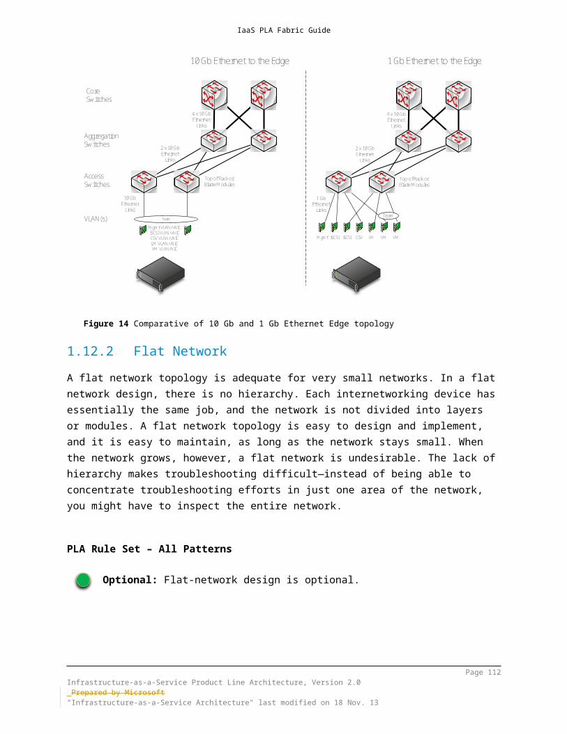
IaaS PLA Fabric Guide
8.4.7Virtual Port ACLsPort ACLs provide a mechanism for isolating networks and metering network traffic for a virtual port on the Hyper-V extensible switch. By using port ACLs, you can meter the IP addresses or MAC addresses that can (or cannot) communicate with a virtual machine. For example, you can use port ACLs to enforce isolation of a virtual machine by letting it talk only to the Internet, or communicate only with a predefined set of addresses. By using the metering capability, you can measure network traffic that is going to or from a specific IP address or MAC address, which lets you report on traffic that is sent or received from the Internet or from network storage arrays.You also can configure multiple port ACLs for a virtual port. Each port ACL consists of a source or destination network address, and a permit to deny or meter action. The metering capability also supplies information about the number of instances where traffic was attempted to or from a virtual machine from a restricted (“deny”) address.
Page 112Infrastructure-as-a-Service Product Line Architecture, Version 2.0 Prepared by Microsoft“Infrastructure-as-a-Service Architecture" last modified on 4 Dec. 13

IaaS PLA Fabric Guide
PLA Rule Set – All Patterns
Optional: The use of Virtual port ACLs are optional.
Design GuidanceAlthough it is technically possible to provide multi-tenancy isolation by using only ACLs, the challenge of managing and keeping all ACLs updated is not a recommended strategy. Virtual Port ACLs are intended to ensure that virtual machines do not spoof their IP or MAC addresses or to control specific network traffic for particular address ranges.Previous versions of ACLs may not provide reasonable value over Extended ACLs, other than for metering. In general, ACLs should be set in a single location to provide ease in troubleshooting.References: http://technet.microsoft.com/library/hh831823.aspx
8.4.7.1 Virtual Switch Extended Port ACLsIn Windows Server 2012 R2, Extended Port ACLs can be configured on the Hyper-V Virtual Switch to allow and block network traffic to and from the virtual machines that are connected to a virtual switch via virtual network adapters. By default Hyper-V allows virtual machines to communicate with each other when connected to the same virtual switch and the network traffic between virtual machines doesn’t leave the physical machine. In these cases, network traffic configurations on the physical network cannot manage traffic between virtual machine. Service providers can greatly benefit from Extended Port ACLs as they can be used to enforce security policies between resources on the fabric infrastructure. The use of Extended Port ACLs is useful in multitenant environments, such as those provided by service providers. Tenants may also enforce security policies through Extended Port ACLs to isolate their own resources. In addition, virtualization has increased the number of security features such as Port ACLs required on physical top-of-rack switches given the many-to-one nature of virtual machine connectivity. Extended Port ACLs could potentially decrease the number of security policies required for the large number of servers in a service provider or large enterprise IaaS fabric infrastructure.
PLA Rule Set – All Patterns
Optional: The use of Virtual Switch Extended Port ACLs are optional.
Page 113Infrastructure-as-a-Service Product Line Architecture, Version 2.0 Prepared by Microsoft“Infrastructure-as-a-Service Architecture" last modified on 4 Dec. 13

IaaS PLA Fabric Guide
Design GuidanceExtended ACLs are configured through PowerShell and apply to all network adapters for a specific virtual machine unless the –VMNetworkAdapterName parameter is specified. This parameter applies to each of the settings identified in this section.References: http://technet.microsoft.com/en-us/library/dn375962.aspx
8.4.8Network VirtualizationIsolating the virtual machines of different departments or customers can be a challenge on a shared network. When entire networks of virtual machines must be isolated, the challenge becomes even greater. Traditionally, VLANs have been used to isolate networks, but VLANs are very complex to manage on a large scale. The following are the primary drawbacks of VLANs:
Cumbersome reconfiguration of production switches is required whenever virtual machines or isolation boundaries must be moved. Moreover, frequent reconfigurations of the physical network for purposes of adding or modifying VLANs increases the risk of an outage.
VLANs have limited scalability because typical switches support no more than 1,000 VLAN IDs (with a maximum of 4,095).
VLANs cannot span multiple Ethernet subnets, which limits the number of nodes in a single VLAN and restricts the placement of virtual machines based on physical location.
Windows Server 2012 R2 Hyper-V Network Virtualization (HNV) enables you to isolate network traffic from different business units or customers on a shared infrastructure, without having to use VLANs. HNV also lets you move virtual machines as needed within your virtual infrastructure while preserving their virtual network assignments. You can even use network virtualization to transparently integrate these private networks into a preexisting infrastructure on another site.HNV extends the concept of server virtualization to permit multiple virtual networks, potentially with overlapping IP addresses, to be deployed on the same physical network. By using HNV, you can set policies that isolate traffic in a dedicated virtual network, independently of the physical infrastructure.To virtualize the network, HNV uses the following elements:
Generic Routing Encapsulation (NVGRE) Policy management server (Virtual Machine Manager) Network Virtualization Gateway server(s)
The potential benefits of network virtualization include the following: Tenant network migration to the cloud with minimum reconfiguration or
effect on isolation. Customers can keep their internal IP addresses while they
Page 114Infrastructure-as-a-Service Product Line Architecture, Version 2.0 Prepared by Microsoft“Infrastructure-as-a-Service Architecture" last modified on 4 Dec. 13

IaaS PLA Fabric Guide
move workloads onto shared IaaS clouds, thus minimizing the configuration changes that are needed for IP addresses, DNS names, security policies, and virtual machine configurations. In software-defined, policy-based data center networks, network traffic isolation does not depend on VLANs, but it is enforced within Hyper-V hosts, based on multi-tenant isolation policies. Network administrators can still use VLANs to manage traffic in the physical infrastructure if the topology is primarily static.
Tenant virtual machine deployment anywhere in the data center. Services and workloads can be placed or migrated to any server in the data center while keeping their IP addresses, without being limited to a physical IP subnet hierarchy or VLAN configurations.
Simplified network design and improved server and network resource use. The rigidity of VLANs, along with the dependency of virtual machine placement on a physical network infrastructure, results in overprovisioning and underuse. By breaking this dependency, virtual networking increases the flexibility of virtual machine workload placement, thus simplifying network management and improving the use of servers and network resources. Placement of server workloads is simplified because migration and placement of workloads are independent of the underlying physical network configurations. Server administrators can focus on managing services and servers, while network administrators can focus on overall network infrastructure and traffic management.
Works with present day hardware (servers, switches, appliances) to promote performance, however modern network adapters with NVGRE Encapsulated Task Offload are recommended. HNV can be deployed in present day data centers, and yet it is compatible with emerging data center “flat network” technologies such as Transparent Interconnection of Lots of Links (TRILL), which is an IETF-standard architecture that is intended to expand Ethernet topologies.
Full management through Windows PowerShell and WMI. While a policy management server such as System Center Virtual Machine Manager is highly recommended, it is possible to use Windows PowerShell to script and automate administrative tasks easily. Windows Server 2012 R2 includes Windows PowerShell cmdlets for network virtualization that let you build command-line tools or automated scripts to configure, monitor, and troubleshoot network isolation policies.
Windows Server 2012 R2 HNV is implemented as part of the Hyper-V virtual switch (whereas Windows Server 2012 implemented this as part of the NDIS filter driver), allowing Hyper-V extensible switch forwarding extensions to co-exist with network virtualization configurations. HNV also supports dynamic IP address learning, which allows for network virtualization to learn of manually assigned or DHCP addresses to set on the virtual network. In environments which use System Center Virtual Machine Manager, once a host learns a new IP address it will notify Virtual Machine
Page 115Infrastructure-as-a-Service Product Line Architecture, Version 2.0 Prepared by Microsoft“Infrastructure-as-a-Service Architecture" last modified on 4 Dec. 13

IaaS PLA Fabric Guide
Manager which adds it to the centralized policy, allowing for rapid dissemination and reduction of overhead associated with the distribution of the network virtualization routing policy. Under Windows Server 2012 R2 HNV is also supported in configurations which also use Windows NIC Teaming.
Windows Server 2012 R2 provides HNV gateway services to support site-to-site virtual private networks, NAT and forwarding between physical locations to support multitenant hosting solutions which leverage network virtualization. This allows service providers and organizations using HNV to support end-to-end communication from either the corporate networks or the Internet to the datacenter running HNV. Without such gateway devices, virtual machines in a virtual network are completely isolated from the outside, and cannot communicate with non-network-virtualized systems such as other systems in the corporate networks or the Internet. The Windows Server 2012 HNV Gateway can encapsulate/decapsulate NVGRE packets based on the centralized network virtualization policy, and can perform the gateway-specific functionality on the resulting native CA packets, such as IP forwarding/routing, NAT, or site-to-site tunneling.
PLA Rule Set – All Patterns
Recommended: Software-defined networking using Hyper-V Network Virtualization is recommended.
Design GuidanceWhile Hyper-V Network Virtualization can be configured using native PowerShell commands, it is highly recommended that a management solution such as System Center Virtual Machine Manager be used in conjunction with this feature, especially in the case of a large Hyper-V cluster environment as described in this document. This is primarily due to the fact that within a large Hyper-V cluster, provider address and customer address mappings and configurations must be synchronized within the TCP timeout window, requiring frequent update to ensure continuity across cluster nodes.The HNV NDIS LWF does not have to be bound to network adapters anymore. Once you attach a network adapter to the virtual switch you can enable HNV simply by assigning a Virtual Subnet ID to a particular virtual network adapter.References:
http://technet.microsoft.com/library/jj134174.aspx http://technet.microsoft.com/library/jj134230.aspx http://social.technet.microsoft.com/wiki/contents/articles/11524.windows-
server-2012-hyper-v-network-virtualization-survival-guide.aspx http://tools.ietf.org/html/draft-sridharan-virtualization-nvgre-01 http://technet.microsoft.com/library/dn383586.aspx
Page 116Infrastructure-as-a-Service Product Line Architecture, Version 2.0 Prepared by Microsoft“Infrastructure-as-a-Service Architecture" last modified on 4 Dec. 13

IaaS PLA Fabric Guide
http://www.microsoft.com/download/details.aspx?id=34782
Page 117Infrastructure-as-a-Service Product Line Architecture, Version 2.0 Prepared by Microsoft“Infrastructure-as-a-Service Architecture" last modified on 4 Dec. 13

IaaS PLA Fabric Guide
9 Compute Architecture
9.1 Server ArchitectureThe host server architecture is a critical component of the virtualized infrastructure, and a key variable in the consolidation ratio and cost analysis. The ability of the host server to handle the workload of a large number of consolidation candidates increases the consolidation ratio and helps provide the desired cost benefit.The system architecture of the host server refers to the general category of the server hardware. Examples include rack mounted servers, blade servers, and large symmetric multiprocessor servers (SMP). The primary tenet to consider when selecting system architectures is that each Hyper-V host will contain multiple guests with multiple workloads. Processor, RAM, storage, and network capacity are critical, as are high I/O capacity and low latency. The host server must be able to provide the required capacity in each of these categories.Note The Windows Server Catalog is useful for assisting customers in selecting appropriate hardware. It contains all servers, storage, and other hardware devices that are certified for Windows Server 2012 R2 and Hyper-V. The logo program and support policy for failover-cluster solutions changed in Windows Server 2012 and Windows Server 2012 R2, and cluster solutions are not listed in the Windows Server Catalog. All individual components that make up a cluster configuration must earn the appropriate "Certified for" or "Supported on" Windows Server 2012 or Windows Server 2012 R2 designations, and they are listed in their device-specific category in the Windows Server Catalog (http://www.windowsservercatalog.com).
PLA Rule Set – All Patterns
Mandatory: Describe the supported and recommended server architecture.
Page 118Infrastructure-as-a-Service Product Line Architecture, Version 2.0 Prepared by Microsoft“Infrastructure-as-a-Service Architecture" last modified on 4 Dec. 13

IaaS PLA Fabric Guide
Rack or Blade-Chassis DesignThe rack or blade-chassis design considerations are primarily hardware vendor specific.
PLA Rule Set – All Patterns
Mandatory: The rack or blade-chassis design must provide redundant power connectivity (multiple power-distribution unit [PDU] capability for racks, or multiple hot-swappable power supplied for blade chassis).
Server and Blade DesignThe server and blade design considerations are primarily hardware vendor specific.
PLA Rule Set – All Patterns
Mandatory: Two- to eight- socket server, with a maximum of 320 logical
processors enabled. Multi-Threading CPU features should be enabled unless they make the number of logical processors exceed 320.
64-bit CPU with virtualization technology support, data-execution prevention (DEP), and second level address translation (SLAT).
64-GB RAM, at a minimum. 4 TB at maximum. Minimum of 40-GB local RAID 1 or 10 hard disk space for OS partition
(or equivalent boot from SAN design).
9.1.1Server and Blade Network ConnectivityUse multiple network adapters or multiport network adapters on each host server. For converged designs, network technologies that provide teaming or virtual network adapters can be utilized, provided that two or more physical adapters can be teamed for redundancy and multiple virtual network adapters or VLANs can be presented to the hosts for traffic segmentation and bandwidth control.
Page 119Infrastructure-as-a-Service Product Line Architecture, Version 2.0 Prepared by Microsoft“Infrastructure-as-a-Service Architecture" last modified on 4 Dec. 13

IaaS PLA Fabric Guide
PLA Rule Set – All Patterns
Mandatory: All servers must provide redundant network connectivity.
Server and Blade High Availability (HA) and Redundancy
PLA Rule Set – All Patterns
Mandatory: If using rack-mounted servers, each server must have redundant
power supplies. If using rack-mounted servers, each server must have redundant
fans. If using blade servers, each chassis must have redundant power
supplies. If using blade servers, each chassis must have redundant fans. If the host system partition uses direct attached storage, each server
must provide a SAS or SATA RAID capability for the system partition.
9.1.2Microsoft Multipath I/O Multipath I/O (MPIO) architecture supports iSCSI, Fibre Channel, and serial attached storage (SAS) SAN connectivity by establishing multiple sessions or connections to the storage array.Multipath solutions use redundant physical path components—adapters, cables, and switches—to create logical paths between the server and the storage device. If one or more of these components should fail (causing the path to fail), multipath logic uses an alternate path for I/O, so that applications can still access their data. Each network adapter (in the iSCSI case) or HBA should be connected by using redundant switch infrastructures, to provide continued access to storage in the event of a failure in a storage fabric component.Failover times vary by storage vendor, and they can be configured by using timers in the Microsoft iSCSI Initiator driver or by modifying the parameter settings of the Fibre Channel host bus adapter driver.In all cases, storage multipath solutions should be used. Generally, storage vendors will build a device-specific module on top of the Multipath I/O (MPIO) software in Windows Server 2012. Each device-specific module and HBA will have its own unique multipath options and recommended number of connections.
Page 120Infrastructure-as-a-Service Product Line Architecture, Version 2.0 Prepared by Microsoft“Infrastructure-as-a-Service Architecture" last modified on 4 Dec. 13

IaaS PLA Fabric Guide
PLA Rule Set – All Patterns
Mandatory: Storage multipathing must be provided to allow the Hyper-V servers
or file servers to maintain storage connectivity, should one storage controller fail.
MPIO must be used with all storage adapters, iSCSI, Fibre Channel or SAS.
Follow MPIO best practices, as documented in the “Windows Server High Availability with Microsoft MPIO” white paper - specifically “Appendix B – MPIO & DSM Configuration and best practices.”
If storage vendor provides its custom MPIO DSM, using that is preferable. Otherwise the default Microsoft DSM may be used.
Design GuidanceReferences:
http://technet.microsoft.com/library/ee619752(v=WS.10).aspx http://technet.microsoft.com/library/ee619749(v=WS.10).aspx http://www.microsoft.com/download/details.aspx?id=30450
9.1.3Consistent Device NamingWindows Server 2012 R2 supports Consistent Device Naming (CDN), which provides the ability for hardware manufacturers to identify descriptive names of onboard network adapters within the BIOS. Windows Server 2012 R2 assigns these descriptive names to each interface, providing users with the ability to match chassis printed interface names with the network interfaces that are created within Windows. The specification for this change is outlined in the Slot Naming PCI-SIG Engineering Change Request.
PLA Rule Set – All Patterns
Optional: The use of Consistent Device Naming is optional.
Page 121Infrastructure-as-a-Service Product Line Architecture, Version 2.0 Prepared by Microsoft“Infrastructure-as-a-Service Architecture" last modified on 4 Dec. 13

IaaS PLA Fabric Guide
9.2 Failover Clustering9.2.1Cluster-Aware UpdatingCluster-aware updating (CAU) reduces server downtime and user disruption by allowing IT administrators to update clustered servers with little or no loss in availability when updates are performed on cluster nodes. CAU transparently takes one node of the cluster offline, installs the updates, performs a restart (if necessary), brings the node back online, and moves on to the next node. This feature is integrated into the existing Windows Update management infrastructure, and it can be further extended and automated with Windows PowerShell for integrating into larger IT automation initiatives.CAU facilitates the cluster updating operation while running from a computer running Windows Server 2012 R2 or Windows 8.1. The computer running the CAU process is called an orchestrator (not to be confused with System Center Orchestrator). CAU supports either of the two following modes of operation: remote-updating mode or self-updating mode. In remote-updating mode, a computer that is remote from the cluster being updated acts as an orchestrator. In self-updating mode, one of the cluster nodes being updated acts as an orchestrator, and it is capable of self-updating the cluster on a user-defined schedule.The end-to-end cluster update process by way of the CAU is cluster-aware, and it is completely automated. It integrates seamlessly with an existing Windows Update Agent (WUA) and Microsoft Windows Server Update Services (WSUS) infrastructure. CAU also includes an extensible architecture that supports new plug-in development to orchestrate any node-updating tools, such as custom software installers, BIOS updating tools, and network adapter/HBA firmware updating tools. After they have been integrated with CAU, these tools, can work across all cluster nodes in a cluster-aware manner.
PLA Rule Set – All Patterns
Mandatory: Automated host updating by using either Cluster Aware Updating or System Center 2012 R2 Virtual Machine Manager must be enabled.
Design GuidanceCAU is only compatible with Windows Server 2012 and Windows Server 2012 R2 Failover Clusters, and the clustered roles supported on Windows Server 2012 and Windows Server 2012 R2. The following pre-requisites must be met:
Cluster nodes must be running Windows Server 2012 or Windows Server 2012 R2
Page 122Infrastructure-as-a-Service Product Line Architecture, Version 2.0 Prepared by Microsoft“Infrastructure-as-a-Service Architecture" last modified on 4 Dec. 13

IaaS PLA Fabric Guide
Design Guidance A sufficient number of cluster nodes must remain available during the update process Cluster nodes must be on a network that is reachable by the Update Coordinator The cluster name must be able to be resolved using DNS If using internal software distribution services (WSUS), cluster nodes must be not be
configured for automatic distribution If the Update Coordinator is not a member of the Failover Cluster being updated, it
has the Failover Clustering Remote Server Administration Tools (RSAT) installed If the Update coordinator is a member of the Failover Cluster being updated, the
cluster has the CAU Role configured for self-updating
To support automatic restarts, the Remote Shutdown Windows Firewall rule group should be enabled on each cluster node.
These rules can also be enabled using the Set-CauClusterRole PowerShell cmdlet:
Set-CauClusterRole –ClusterName <ClusterName> -EnableFirewallRules It is recommended that the cluster be validated for updating readiness in the following situations:
Before using CAU for the first time to apply software updates. After adding a node to the cluster or perform other hardware changes in the cluster
that require running the Validate a Cluster Wizard. After changing an update source, or change update settings or configurations that
can affect the application of updates on the nodes.
It is a best practice to manage all CAU Run Profiles on a single File Share accessible to all potential CAU Update Coordinators.References:
http://technet.microsoft.com/library/hh831694.aspx http://blogs.technet.com/b/filecab/archive/2012/05/17/starting-with-cluster-
aware-updating-self-updating.aspx http://technet.microsoft.com/library/hh831694.aspx http://technet.microsoft.com/library/jj134234.aspx http://northamerica.msteched.com/topic/details/2012/WSV322
9.2.2Cluster Shared Volumes The Cluster Shared Volumes (CSV) feature was introduced in Windows Server 2008 R2 as a more efficient way for administrators to deploy storage for
Page 123Infrastructure-as-a-Service Product Line Architecture, Version 2.0 Prepared by Microsoft“Infrastructure-as-a-Service Architecture" last modified on 4 Dec. 13

IaaS PLA Fabric Guide
cluster-enabled virtual machines on Hyper-V clusters and later other server roles, such as Scale-Out File Servers and SQL Server. Before CSVs, administrators had to provision a LUN on shared storage for each virtual machine, so that each machine had exclusive access to its virtual hard disks, and mutual write conditions could be avoided. By using CSVs, all cluster hosts have simultaneous access to a single or multiple shared volume(s) where storage for multiple virtual machines can be hosted,—thus, there is no need to provision a new LUN whenever you created a new virtual machine.Windows Server 2012 R2 provides the following CSV capabilities:
Flexible application and file storage: Cluster Shared Volumes extends its potential benefits beyond Hyper-V to support other application workloads and flexible file storage solutions. CSV 2.0 provides capabilities to clusters through shared namespaces to share configurations across all cluster nodes, including the ability to build continuously available cluster-wide file systems. Application storage can be served from the same share as data, eliminating the need to deploy two clusters (an application and a separate storage cluster) to support true highly availability application scenarios.
Integration with other features of Windows Server 2012 R2: Allows for inexpensive scalability, reliability, and management simplicity through tight integration with Storage Spaces. You gain high performance and resiliency capabilities with SMB Direct and SMB Multichannel, and create more efficient storage with thin provisioning. In addition, Windows Server 2012 R2 supports ReFS, data deduplication, parity and tiered Storage Spaces as well as Storage Spaces write-back cache.
Single namespace: Provides a single consistent file namespace where files have the same name and path when viewed from any node in the cluster. CSV volumes are exposed as directories and subdirectories under the ClusterStorage root directory.
Improved backup and restore: Supports several backup and restore capabilities, including support for the full feature set of VSS and support for hardware and software backup of CSV volumes. CSVs also offer a distributed backup infrastructure for software snapshots. The Software Snapshot Provider coordinates creating a CSV 2.0 snapshot, point-in-time semantics at a cluster level, and the ability to perform remote snapshots.
Optimized Placement Policies: CSV ownership is evenly distributed across the failover cluster nodes based on the number of CSVs that each node owns. It is automatically rebalanced when certain conditions occur such as restart, failover and addition of cluster nodes.
Increased Resiliency: As described earlier, the SMB Server service is comprised of multiple instances per failover cluster node - a default instance that handles incoming traffic from SMB clients that access regular file shares, and a second CSV instance that handles only inter-node CSV metadata
Page 124Infrastructure-as-a-Service Product Line Architecture, Version 2.0 Prepared by Microsoft“Infrastructure-as-a-Service Architecture" last modified on 4 Dec. 13

IaaS PLA Fabric Guide
access and redirected I/O traffic between nodes. This improves the scalability of inter-node SMB traffic between CSV nodes.
CSV Cache: Allows for the system memory (RAM) as a write-through cache. The CSV Cache provides caching of read-only unbuffered I/O, which can improve performance for applications which use unbuffered I/O when accessing files (e.g. Hyper-V). CSV Cache delivers caching at the block level, which enables it to perform caching of pieces of data being accessed within the VHD file. CSV Block Cache reserves its cache from system memory and handles orchestration across the sets of nodes in the cluster. In Windows Server 2012 R2 CSV Cache is enabled by default and you can allocate up 80% of the total physical RAM for CSV write-through cache.
There are several CSV deployment models which are outlined in the sections below.
9.2.2.1 Single CSV per ClusterIn the “single CSV per cluster” design pattern, the SAN is configured to present a single large LUN to all the nodes in the host cluster. The LUN is configured as a CSV in failover clustering. All files that belong to the virtual machines that are hosted on the cluster are stored on the CSV. Optionally, data deduplication functionality that is provided by the SAN can be utilized (if it is supported by the SAN vendor).
Figure 15 Virtual machine on a single large CSV
9.2.2.2 Multiple CSVs per ClusterIn the “multiple CSVs per cluster” design pattern, the SAN is configured to present two or more large LUNs to all the nodes in the host cluster. The LUNs are configured
Page 125Infrastructure-as-a-Service Product Line Architecture, Version 2.0 Prepared by Microsoft“Infrastructure-as-a-Service Architecture" last modified on 4 Dec. 13

IaaS PLA Fabric Guide
as CSVs in failover clustering. All virtual machine–related files are hosted on the cluster are stored on the CSVs. In addition, data deduplication functionality that the SAN provides can be utilized (if supported by the SAN vendor).
Figure 16 Virtual machines on multiple CSVs, with minimal segregation
For the single and multiple CSV patterns, each CSV has the same I/O characteristics, so that each individual virtual machine has all of its associated virtual hard disks (VHDs) stored on one of the CSVs.
Page 126Infrastructure-as-a-Service Product Line Architecture, Version 2.0 Prepared by Microsoft“Infrastructure-as-a-Service Architecture" last modified on 4 Dec. 13

IaaS PLA Fabric Guide
Figure 17 The virtual disks of each virtual machine reside on the same CSV
9.2.2.3 Multiple I/O Optimized CSVs per ClusterIn the “multiple I/O optimized CSVs per cluster” design pattern, the SAN is configured to present multiple LUNs to all the nodes in the host cluster; however, the LUNs are optimized for particular I/O patterns like fast sequential read performance, or fast random write performance. The LUNs are configured as CSV in failover clustering. All VHDs that belong to the virtual machines that are hosted on the cluster are stored on the CSVs, but they are targeted to the appropriate CSV for the given I/O needs.
Page 127Infrastructure-as-a-Service Product Line Architecture, Version 2.0 Prepared by Microsoft“Infrastructure-as-a-Service Architecture" last modified on 4 Dec. 13

IaaS PLA Fabric Guide
Storage
Host Boot Volumes(if boot from SAN)
CSV Volume 3VM Logging / sequential W I/O
CSV Volume 1VM Operating Systems
CSV Volume 4VM Staging, P2V, V2V
CSV Volume 5VM Configuration files,Volatile Memory, Pagefiles,
Host Cluster CSV Volumes (per Cluster)
CSV Volume 2VM Database / random R/W I/O
DataDeDupe
NoDataDeDupe
Host Cluster Witness Disk Volumes
SAN
Figure 18 Virtual machines with a high degree of virtual disk segregation
In the “multiple I/O optimized CSVs per cluster” design pattern, each individual virtual machine has all of its associated VHDs stored on the appropriate CSV, per required I/O requirements.
OS VHD
Data VHD
Logs VHD
VirtualMachine
CSV Volume 3VM Logging / sequential W I/O
CSV Volume 1VM Operating Systems
CSV Volume 2VM Database / random R/W I/O
Figure 19 Virtual machines with a high degree of virtual disk segregation
Note A single virtual machine can have multiple VHDs and each VHD can be stored on a different CSV (provided that all CSVs are available to the host cluster on which the virtual machine is created).
Page 128Infrastructure-as-a-Service Product Line Architecture, Version 2.0 Prepared by Microsoft“Infrastructure-as-a-Service Architecture" last modified on 4 Dec. 13

IaaS PLA Fabric Guide
PLA Rule Set – All Patterns
Mandatory: Use of CSV is required for all patterns.
Design GuidanceThe NTLM authentication requirement (with a Domain Controller) that existed in CSV v1.0 (Windows Server 2008 R2) has been removed in Windows Server 2012 R2 Failover Clusters.In Windows Server 2008 R2, CSV volumes were custom reparse points. In Windows Server 2012, CSV volumes are standard mount points as reparse points are not supported in CSVv2. Standard mount points provide better interoperability with performance counters, monitoring of free space on CSV volumes and backup software.The inbox Windows Server Backup feature does not support backing up virtual machines being hosted on Failover Cluster CSV volumes. The data on the CSV volume can be backed up but not in the context of a virtual machine back up. Third Party backup applications and Microsoft's Data Protection Manager should be used instead.CSV is designed for single shared LUNs; multi-site clusters, commonly referred to as geographically dispersed or stretched clusters, where nodes in the same cluster reside in dissimilar network subnets. In Windows Server 2008 R2, cluster nodes residing on dissimilar (routed) subnets could not use CSV, however, in Windows Server 2012 and Windows Server 2012 R2 this is no longer a limitation.CSV block caching primarily benefits VDI scenarios, VM boot storms, VHD provisioning, and differencing VHD’s. Pooled VMs will see the greatest benefit. Workloads that may not see as large a benefit are workloads that are mostly writes (as CSV block cache is only for Read I/O), have very large sequential reads (as cached data may be purged) and those which are random in its I/O pattern (as block access is random and the effects of caching is mitigated). In Windows Server 2012 20% and with Windows Server 2012 R2 of the total physical RAM for CSV write-through cache, which will be consumed from non-paged pool memory.512 MB is expected as the recommend default value. Two configuration settings are available for CSV Cache:
EnableBlockCache (named CsvEnableBlockCache in Windows Server 2012) – A private property on the Physical Disk resource that enables caching to all CSV volumes on a given LUN. In Windows Server 2012 R2 this property is enabled by default.
SharedVolumeBlockCacheSizeInMB – A cluster common property that can be used to set the size of the cache. A value of 0 indicates that the feature is disabled and any other value indicates the size of the cache. This property is cluster wide can be adjusted without downtime. It requires the previous setting (enabling CSV cache on an individual disk) and for the setting to take effect, the Physical Disk resource must be taken offline and brought online again. This setting is configured via PowerShell using the following command:
Page 129Infrastructure-as-a-Service Product Line Architecture, Version 2.0 Prepared by Microsoft“Infrastructure-as-a-Service Architecture" last modified on 4 Dec. 13

IaaS PLA Fabric Guide
Design Guidance(Get-Cluster <cluster name>).SharedVolumeBlockCacheSizeInMB = <value>
References: http://technet.microsoft.com/library/ee830307.aspx http://technet.microsoft.com/library/jj612868.aspx http://blogs.msdn.com/b/clustering/archive/2012/04/06/10291490.aspx http://blogs.msdn.com/b/clustering/archive/2012/03/22/10286676.aspx http://technet.microsoft.com/library/dn265972.aspx#BKMK_CSVInterop
9.2.2.4 BitLocker-Encrypted Cluster VolumesHyper-V, failover clustering, and BitLocker work together to create an ideal, highly secure platform for private cloud infrastructure. Windows Server 2012 R2 cluster disks encrypted with BitLocker Drive Encryption enable better physical security for deployments outside secure data centers (providing that there is a critical safeguard for private cloud infrastructure) and help protect against data leaks.
PLA Rule Set – All Patterns
Recommended: BitLocker-encrypted CSV is recommended for any deployments that lack strong physical security and access controls to servers.
Design GuidanceAlthough BitLocker can be enabled either before or after a disk is added to the cluster, it is recommended for new installations to enable this as early as possible since if a disk is already in the cluster, it must be put into Maintenance Mode to be encrypted.An Active Directory SID Protector using the Cluster Named Object (CNO) account must be added with cluster disks because they move between the nodes in the cluster. This can be performed using either of the following commands:
PowerShell: Add-BitLockerKeyProtector <drive letter or CSV mount point> -ADAccountOrGroupProtector –ADAccountOrGroup <CNO>$
Manage-BDE: manage-bde.exe <drive letter or CSV mount point> -protectors -add -sid <CNO>$
During encryption, CSV Volume will be in redirected mode until BitLocker builds its metadata and watermark on all data present on the encrypted volume. The duration proportional to the size of the volume, the real data size and BitLocker encryption mode picked (DataOnly or Full). Once encryption has completed, the cluster service will switch
Page 130Infrastructure-as-a-Service Product Line Architecture, Version 2.0 Prepared by Microsoft“Infrastructure-as-a-Service Architecture" last modified on 4 Dec. 13
IaaS PLA Fabric Guide
to Direct I/O mode within 3 minutes.BitLocker PowerShell module or Manage-BDE are the methods used for encrypting cluster disks as the BitLocker Control Panel applet cannot be used on volumes without drive letters assigned.References:
http://blogs.msdn.com/b/clustering/archive/2012/07/20/10332169.aspx http://technet.microsoft.com/library/hh831713
9.3 Hyper-V Failover ClusteringA Hyper-V host failover cluster is a group of independent servers that work together to increase the availability of applications and services. The clustered servers (which are called nodes) are connected by physical cables and software. If one of the cluster nodes fails, another node begins to provide service—a process that is known as failover. In the case of a planned live migration, users will experience no perceptible service interruption.The host servers are one critical component of a dynamic, virtual infrastructure. Consolidation of multiple workloads onto the host servers requires that those servers be highly available. Windows Server 2012 R2 provides advances in failover clustering that enable high availability and live migration of virtual machines between physical nodes.
9.3.1Host Failover-Cluster TopologyIt is recommended that the server topology consist of at least two Hyper-V host clusters. The first needs at least two nodes, and it is referred to as the fabric management cluster. The second, plus any additional clusters, is referred to as fabric host clusters.In scenarios of smaller scale or specialized solutions, the management and fabric clusters can be consolidated onto the fabric host cluster. Special care has to be taken to provide resource availability for the virtual machines that host the various parts of the management stack.Each host cluster can contain up to 64 nodes. Host clusters require some form of shared storage such as a Storage Space, Scale-Out File Server cluster, Fibre Channel, or iSCSI SAN.
9.3.2Cluster Quorum and Witness ConfigurationsIn quorum configurations, every cluster node has one vote, and a witness (disk or file share) also has one vote. A witness (disk or file share) is recommended when
Page 131Infrastructure-as-a-Service Product Line Architecture, Version 2.0 Prepared by Microsoft“Infrastructure-as-a-Service Architecture" last modified on 4 Dec. 13

IaaS PLA Fabric Guide
the number of voting nodes is even, but it is not required when the number of voting nodes is odd. It is always recommended to keep the total number of votes in a cluster as odd. Therefore, a cluster witness should be configured to support Hyper-V cluster configurations when the number of failover cluster nodes is even.Choices for a cluster witness include a shared disk witness and a file-share witness. There are distinct differences between these two models. A disk witness consists of a dedicated LUN to serve as the quorum disk that is used as an arbitration point. A disk witness stores a copy of cluster database for all nodes to share. It is recommended that this disk consist of a small partition that is at least 512 MB in size; however, it is commonly recommended to reserve a 1 GB disk for each cluster. This LUN can be NTFS- or ReFS-formatted and does not require the assignment of a drive letter.File-share witness configurations use a simple, unique file share that is located on a file server to support one or more clusters. This file share must have write permissions for the cluster name object (CNO), along with all of the nodes. It is highly recommended that this file share exist outside any of the cluster nodes, and therefore, carry the requirement of additional physical or virtual servers outside the Hyper-V compute cluster within the fabric. Writing to this share results in minimal network traffic, because all nodes contain separate copies of the cluster database, and only cluster membership changes are written to the share. The additional challenge that this creates is that file-share witness configurations are susceptible to “split” or “partition in time” scenarios and could create situations in which surviving nodes and starting nodes have different copies of the cluster database2. File-share witness disks should be used only in configurations in which no shared disk infrastructure exists.Additional quorum and witness capabilities in Windows Server 2012 R2 include:
Dynamic witness: By default Windows Server 2012 R2 clusters are configured to use dynamic quorum, which allows the witness vote to be dynamically adjusted and reduces the risk that the cluster will be impacted by witness failure. Using this configuration the cluster decides whether to use the witness vote based on the number of voting nodes that are available in the cluster, simplifying the witness configuration. In addition, a Windows Server 2012 R2 cluster can dynamically adjust a running node’s vote to keep the total number of votes at an odd number which allows the cluster to continue to run in the event of a 50% node split where neither side would normally have quorum.
Force quorum resiliency: This change allows for the ability to force quorum in the event of a partitioned cluster. A partitioned cluster occurs when a cluster breaks into subnets that are not aware of each other and the service is restarted by forcing quorum.
2 http://technet.microsoft.com/en-us/library/cc770830(v=WS.10).aspx
Page 132Infrastructure-as-a-Service Product Line Architecture, Version 2.0 Prepared by Microsoft“Infrastructure-as-a-Service Architecture" last modified on 4 Dec. 13

IaaS PLA Fabric Guide
PLA Rule Set - Software Defined Infrastructure
Mandatory: A disk-based or file share witness must be provided for every cluster.
Recommended: A file-share witness on a separate node should be used to provide quorum capabilities in configurations in which no shared disk exists. (E.g. a Hyper-V cluster that leverages SMB for VM storage).
PLA Rule Set – Converged and Non-Converged
Mandatory: A disk-based or file share witness must be provided for every cluster.
Recommended: A witness disk should be used for all clusters where shared disks are possible.
Design GuidanceFrom a design perspective, the guidance stated above should define the quorum option (file share or disk witness) to be used in a given private cloud configuration – for configurations in which no shared disk exists (Software Defined Infrastructure Variant A and C primarily), a file-share witness on a separate node over a witness disk should be used to provide quorum capabilities to the cluster. For other architectural patterns (Converged, Non-Converged and configurations of the Software Defined Infrastructure pattern where a shared disk is available via SAN – such as Variant B) a witness disk over a file-share witness should be used to provide node and disk majority for all clusters in the fabric and fabric management clusters.References: http://technet.microsoft.com/en-us/library/jj612870.aspx
9.3.3Host Cluster NetworksA variety of host cluster networks are required for a Hyper-V failover cluster. The network requirements help enable high availability and high performance. The specific requirements and recommendations for network configuration are published on in the TechNet Library in the Hyper-V: Live Migration Network Configuration Guide (http://technet.microsoft.com/library/ff428137.aspx) . Note that the list below provides some examples, and does not contain all network access types (for instance some implementations would include a dedicated backup network).
Page 133Infrastructure-as-a-Service Product Line Architecture, Version 2.0 Prepared by Microsoft“Infrastructure-as-a-Service Architecture" last modified on 4 Dec. 13

IaaS PLA Fabric Guide
Network Access Type
Purpose of the network-access type
Network-traffic requirements
Recommended network access
Storage Access storage through SMB, iSCSI, or Fibre Channel. (Fibre Channel does not need a network adapter.)
High bandwidth and low latency.
Usually, dedicated and private access. Refer to your storage vendor for guidelines.
Virtual machine access
Workloads that run on virtual machines usually require external network connectivity to service client requests.
Varies. Public access, which could be teamed for link aggregation or to fail over the cluster.
Management Managing the Hyper-V management operating system. This network is used by Hyper-V Manager or System Center Virtual Machine Manager (VMM).
Low bandwidth. Public access, which could be teamed to fail over the cluster.
Cluster and Cluster Shared Volumes (CSV)
Preferred network that is used by the cluster for communications to maintain cluster health. Also, used by CSV to send data between owner and non-owner nodes. If storage access is interrupted, this network is used to access the CSV or to maintain and back up the CSV.The cluster should have access to more than one network for communication
Usually, low bandwidth and low latency. Occasionally, high bandwidth.
Private access.
Page 134Infrastructure-as-a-Service Product Line Architecture, Version 2.0 Prepared by Microsoft“Infrastructure-as-a-Service Architecture" last modified on 4 Dec. 13
IaaS PLA Fabric Guide
to help make sure that it is a high availability cluster.
Live migration Transfer virtual machine memory and state.
High bandwidth and low latency during migrations.
Private access
Table 9 Network access types
9.3.3.1 Management NetworkA dedicated management network is required so that hosts can be managed through a dedicated network to prevent competition with guest traffic needs. A dedicated network provides a degree of separation for the purposes of security and ease of management. A dedicated management network typically implies dedicating a network adapter per host and port per network device to the management network.Additionally, many server manufacturers also provide a separate out-of-band (OOB) management capability that enables remote management of server hardware outside the host operating system.
PLA Rule Set – All Patterns
Mandatory: Implement a dedicated network for management of the infrastructure. Make sure that all Hyper-V hosts have a dedicated network adapter (or VLAN within a NIC Team and Trunk) connected to the management network for exclusive use by the parent partition.
Recommended: If the chosen server hardware supports an out-of-band management adapter, establish a dedicated LAN for these adapters.
9.3.3.2 iSCSI NetworkIf using iSCSI, a dedicated iSCSI network is required, so that storage traffic is not in contention with any other traffic. This typically implies dedicating two network adapters per host and two ports per network device to the management network.
Page 135Infrastructure-as-a-Service Product Line Architecture, Version 2.0 Prepared by Microsoft“Infrastructure-as-a-Service Architecture" last modified on 4 Dec. 13

IaaS PLA Fabric Guide
PLA Rule Set – Converged and Non-Converged
Mandatory: If using iSCSI, implement a dedicated iSCSI network or VLAN. If using either 1 GbE or 10 GbE NICs, make sure that at least two NICs are dedicated to iSCSI traffic and that MPIO is enabled, to promote redundancy.
Recommended: A witness disk should be used for all clusters where shared disks are possible.
9.3.3.3 CSV/Cluster Communication NetworkUsually, when the cluster node that owns a VHD file in a CSV performs disk I/O, the node communicates directly with the storage. However, storage connectivity failures sometimes prevent a given node from communicating directly with the storage. To maintain functionality until the failure is corrected, the node redirects the disk I/O through a cluster network (the preferred network for CSV) to the node where the disk is currently mounted. This is called CSV redirected I/O mode.
PLA Rule Set – All Patterns
Mandatory: Implement a dedicated CSV/cluster communication network. If using non-teamed Ethernet NICs, confirm that all Hyper-V hosts have a dedicated network adapter connected to the CSV network for exclusive use by the parent partition. If using teamed NICs, confirm that a virtual NIC is presented to the parent partition for CSV traffic.
9.3.3.4 Live-Migration NetworkDuring live migration, the contents of the memory of the virtual machine that is running on the source node must be transferred to the destination node over a LAN connection. To enable high-speed transfer, a dedicated live-migration network is required.
PLA Rule Set – All Patterns
Mandatory: Implement a dedicated live-migration network. If using non-teamed Ethernet NICs, confirm that all Hyper-V hosts have a dedicated network adapter connected to the LM network for exclusive use by the parent partition. If using teamed NICs, confirm that a virtual NIC is presented to the parent partition for LM traffic.
Page 136Infrastructure-as-a-Service Product Line Architecture, Version 2.0 Prepared by Microsoft“Infrastructure-as-a-Service Architecture" last modified on 4 Dec. 13
IaaS PLA Fabric Guide
9.3.3.5 Virtual Machine Network(s)The virtual machine networks are dedicated to virtual machine LAN traffic. A virtual machine network can be two or more 1 GbE networks, one or more networks that have been created through NIC Teaming, or virtual networks that have been created from shared 10 GbE network adapters.
PLA Rule Set – All Patterns
Mandatory: Implement one or more dedicated virtual machine networks. If using 1-GB Ethernet NICs, make sure that all Hyper-V hosts have two or more dedicated network adapters connected to the virtual machine network for exclusive use by the guest virtual machines. If using 10 GbE NICs, confirm that a teamed, virtual NIC is presented to the virtual switch, to promote redundancy.
9.3.4Hyper-V Application MonitoringWith Windows Server 2012 R2, Hyper-V and failover clustering work together to bring higher availability to workloads that do not support clustering. They do so by providing a lightweight, simple solution to monitor applications that are running on virtual machines and by integrating with the host. By monitoring services and event logs inside the virtual machine, Hyper-V and failover clustering can detect if the key services that a virtual machine provides are healthy. If necessary, they provide automatic corrective action such as restarting the virtual machine or restarting a service within the virtual machine.
PLA Rule Set – All Patterns
Optional: Hyper-V application monitoring is optional.
Design GuidanceReferences:
http://msdn.microsoft.com/library/hh850068.aspx http://blogs.msdn.com/b/clustering/archive/2012/04/18/10295158.aspx
Page 137Infrastructure-as-a-Service Product Line Architecture, Version 2.0 Prepared by Microsoft“Infrastructure-as-a-Service Architecture" last modified on 4 Dec. 13

IaaS PLA Fabric Guide
9.3.5Virtual Machine Failover PrioritizationVirtual machine priorities can be configured to control the order in which specific virtual machines fail over or start. This helps make sure that high-priority virtual machines get the resources that they need and that lower-priority virtual machines are given resources as they become available.
PLA Rule Set – All Patterns
Optional: Virtual machine failover prioritization is optional.
Design GuidanceThe Role property pages for a highly available virtual machine are similar to the property pages for other roles supported in the cluster. One of the more important settings with respect to a virtual machine role, however, is the Priority setting on the General tab:
The Role Priority settings are - Low, Medium (Default), High, and No Auto Start. This setting determines which Roles have priorities over others. With respect to the Virtual Machine Role, the Priority setting indicates which workloads have priority over others when the cluster first starts and during VM Mobility scenarios. For example, when the cluster first starts, all High priority roles are brought online first, then the Medium, and so on until the resource limits of the cluster are reached (meaning cluster will continue to bring the resources online until they are all online or there are no more nodes in the cluster with resources available to host the virtual workloads). When nodes reaches its resource limit, roles are distributed to other nodes in the cluster. When the cluster service is placing virtual workloads on the cluster nodes when the cluster starts, the following logic is used:
Place a virtualized workload on the same node it was running on before the cluster was restarted
Place a virtual workload on a node in the cluster that is part of the Preferred Owners list for the resource group
If a node, that hosted virtual workloads before the cluster was restarted, is no longer part of the cluster (in the current view of the cluster), the cluster will place those workloads on other nodes in the cluster based on available resources (mostly
Page 138Infrastructure-as-a-Service Product Line Architecture, Version 2.0 Prepared by Microsoft“Infrastructure-as-a-Service Architecture" last modified on 4 Dec. 13
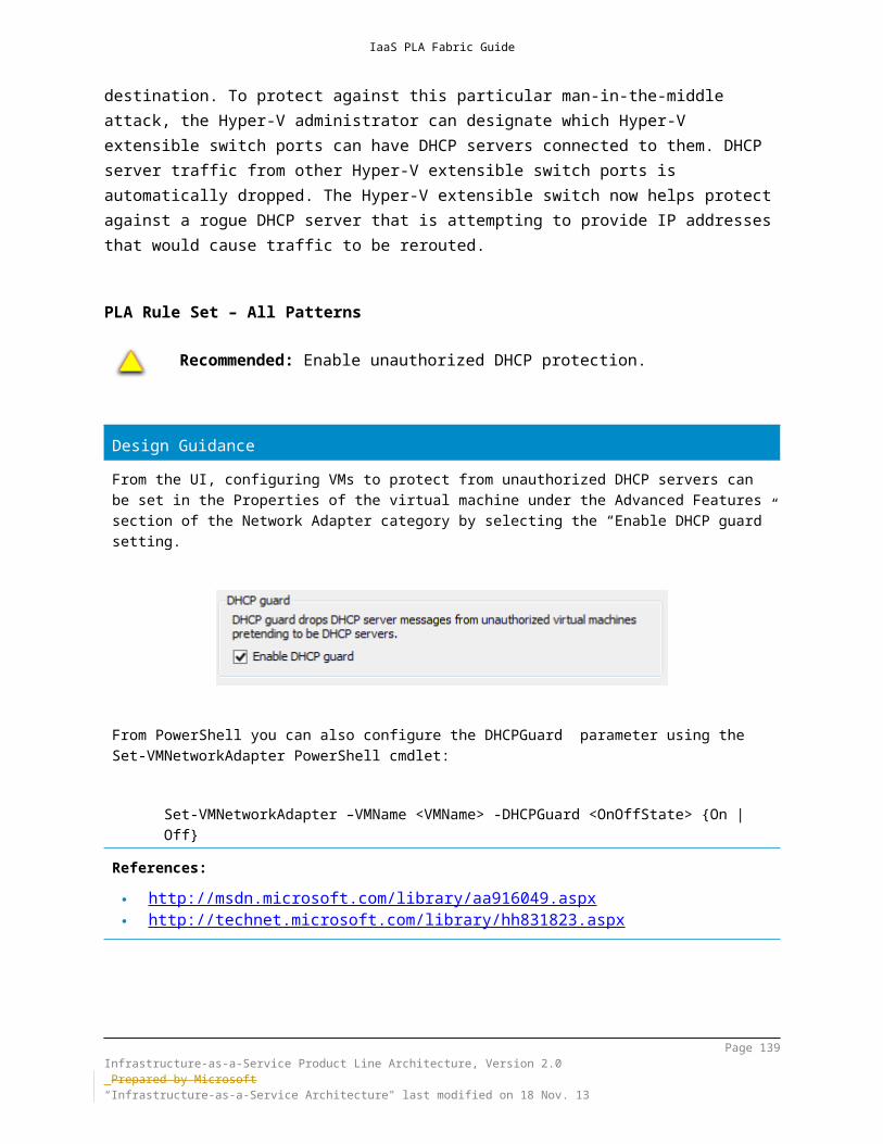
IaaS PLA Fabric Guide
Design Guidancememory resources) available on the nodes
If virtual machine workloads cannot be brought online, cluster continues to poll all the nodes in the cluster (every 5 minutes) to determine if any resources are available to bring additional workloads online. When cluster resources become available, the virtual workloads are brought online.
References: http://technet.microsoft.com/library/hh831414.aspx
Page 139Infrastructure-as-a-Service Product Line Architecture, Version 2.0 Prepared by Microsoft“Infrastructure-as-a-Service Architecture" last modified on 4 Dec. 13

IaaS PLA Fabric Guide
9.3.6Virtual Machine Anti-AffinityAdministrators can specify that two specific virtual machines cannot coexist on the same node in a failover scenario. By leveraging anti-affinity, workloads resiliency guidelines can be respected when hosted on a single failover cluster.
PLA Rule Set – All Patterns
Optional: Virtual machine anti-affinity rules are optional.
Design GuidanceWhen a group is moved during failover, anti-affinity affects the algorithm used to determine the destination node as follows:
1. Using the preferred owner list of the group being moved, the Cluster service finds the next preferred node.
2. If the node is not hosting any group anti-affined with the group being moved, it is selected as the destination node.
3. If the next preferred available node is currently hosting a group anti-affined with the group being moved, the Cluster service moves to the next preferred available node in the preferred owner list.
4. If the only available nodes are hosting anti-affined groups, the Cluster service ignores anti-affinity and selects the next preferred available node as the destination node.
Because of the behaviour described in point 4 above, anti-affinity does not guarantee that groups will never be hosted by the same node. A Cluster common property called ClusterEnforcedAntiAffinity is available in Windows Server 2012 and Windows Server 2012 R2 to enforce the abovementioned logic. This would prevent a VM from coming online on a node where another VM from the same Availability Group reside.References:
http://blogs.msdn.com/b/clustering/archive/2010/12/14/10104402.aspx http://blogs.msdn.com/b/clustering/archive/2009/08/11/9864574.aspx http://msdn.microsoft.com/library/windows/desktop/aa369651.aspx
9.3.7Virtual Machine Drain on ShutdownWindows Server 2012 R2 supports shutting down a Hyper-V failover cluster node without first putting the node into maintenance mode to drain any running clustered roles, the cluster now automatically live migrates all running virtual machines to another host before the computer shuts down.
Page 140Infrastructure-as-a-Service Product Line Architecture, Version 2.0 Prepared by Microsoft“Infrastructure-as-a-Service Architecture" last modified on 4 Dec. 13

IaaS PLA Fabric Guide
Design GuidanceIn Windows Server 2012 R2 virtual machine drain on shutdown functionality is enabled by default. To enable or disable this functionality, configure the DrainOnShutdown cluster common property. By default, this property is enabled (set to a value of "1"). The following PowerShell command is provided to view the property value:
(Get-Cluster).DrainOnShutdown
References: http://technet.microsoft.com/library/dn265972.aspx
9.3.8Shared Virtual Hard DiskWindows Server 2012 R2 Hyper-V includes support for virtual machines to leverage shared VHDX files for shared storage scenarios such as Guest Clustering. Both shared and non-shared virtual hard disk files attached as virtual SCSI disks appear as virtual SAS disks when you add a SCSI hard disk to a virtual machine.
PLA Rule Set - Software Defined Infrastructure
Recommended: The use of shared virtual hard disks for the purposes of guest clustering is recommended.
PLA Rule Set – Converged and Non-Converged
Optional: The use of shared virtual hard disks for the purposes of guest clustering is optional.
Design GuidanceShared VHDX has several limitations which should be noted. Specifically, the following functionality is not supported when using shared VHDX:
Hyper-V Replica Resizing Storage Live Migration Host level VSS backups - guest level backup should be performed using the same
techniques as you would for a cluster on bare metal VM snapshots/checkpoints (this would require synchronization across all the virtual
machines sharing the VHDX)
Adding a shared VHDX to a running virtual machine is supportedShared VHDX should not be used for the operating system virtual hard disk
Page 141Infrastructure-as-a-Service Product Line Architecture, Version 2.0 Prepared by Microsoft“Infrastructure-as-a-Service Architecture" last modified on 4 Dec. 13

IaaS PLA Fabric Guide
Design GuidanceMicrosoft officially only supports Windows Server 2012 and Windows Server 2012 R2 guests as this is what was officially tested. Technically other guest operating systems including Windows Server 2008 and Windows Server 2008 R2 will work as well but the Integrated Components in the guest must be updated to the latest version. Windows Server 2003 or lower guest operating systems will not work as they do not support the necessary SCSI commands.References:
http://technet.microsoft.com/library/dn265980.aspx http://technet.microsoft.com/library/dn265972.aspx#BKMK_SharedVHDX http://channel9.msdn.com/Events/TechEd/NorthAmerica/2013/MDC-
B311#fbid=WOoBzkT2vlt
Page 142Infrastructure-as-a-Service Product Line Architecture, Version 2.0 Prepared by Microsoft“Infrastructure-as-a-Service Architecture" last modified on 4 Dec. 13

IaaS PLA Fabric Guide
10 Hyper-V Virtualization Architecture
10.1 Hyper-V Features10.1.1 Hyper-V Host and Guest Scale-UpWindows Server 2012 R2 Hyper-V supports running on a host system that has up to 320 logical processors on hardware and 4 terabytes (TB) of physical memory. This helps encourage compatibility with the largest scale-up server systems.Hyper-V in Windows Server 2012 R2 lets you configure a virtual machine with up to 64 virtual processors and up to 1 TB of memory, to support very large workload scenarios.Hyper-V in Windows Server 2012 R2 also supports running up to 8,000 virtual machines on a 64-node failover cluster. This is a significant improvement over Windows Server 2008 R2 Hyper-V, which supported a maximum of 16 cluster nodes and 1,000 virtual machines per cluster.
10.1.2 Hyper-V over SMB 3.0Prior to Windows Server 2012, remote storage options for Hyper-V were limited to expensive Fibre Channel or iSCSI SAN solutions that were difficult to provision for Hyper-V guests or other more inexpensive options that did not offer many features. By enabling Hyper-V to use SMB file shares for virtual storage, administrators have a new option that is simple to provision with support for CSV and inexpensive to deploy, but also offers performance capabilities and features that rival those available with Fibre Channel SANs. As outlined earlier in the Storage Architecture section, SMB 3.0 can be leveraged for SQL and Hyper-V workloads. Hyper-V over SMB requires:
One or more computers running Windows Server 2012 R2, with the Hyper-V and File and Storage Services roles installed.
A common Active Directory infrastructure. (The servers that are running AD DS do not have to run Windows Server 2012 R2)
Failover clustering on the Hyper-V side, on the File and Storage Services side, or both. Failover clustering is not required.
Hyper-V over SMB supports a variety of flexible configurations that offer several levels of capabilities and availability, which include single-node, dual-node, and multi-node file server modes.
Page 143Infrastructure-as-a-Service Product Line Architecture, Version 2.0 Prepared by Microsoft“Infrastructure-as-a-Service Architecture" last modified on 4 Dec. 13

IaaS PLA Fabric Guide
PLA Rule Set - Software Defined Infrastructure
Mandatory: The use of Hyper-V over SMB3 is mandatory.
PLA Rule Set – Converged and Non-Converged
Not applicable
Design GuidanceRefer to the previous sections surrounding SMB3 design guidance when establishing SMB shares for Hyper-V storage. The following additional references are provided below.References:
http://technet.microsoft.com/library/jj134187.aspx http://channel9.msdn.com/Events/TechEd/Europe/2012/VIR306 http://blogs.technet.com/b/josebda/archive/2012/08/24/test-hyper-v-over-
smb-configuration-with-windows-server-2012-step-by-step-installation.aspx
10.1.3 Virtual Machine MobilityHyper-V live migration makes it possible to move running virtual machines from one physical host to another with no effect on the availability of virtual machines to users. Hyper-V in Windows Server 2012 R2 introduces faster and simultaneous live migration inside or outside a clustered environment.In addition to providing live migration in the most basic of deployments, this functionality facilitates more advanced scenarios, such as performing a live migration to a virtual machine between multiple, separate clusters to balance loads across an entire data center.If you use live migration you will see that live migrations can now use higher network bandwidths (up to 10 gigabits) to complete migrations faster. You can also perform multiple simultaneous live migrations to move many virtual machines quickly.
Page 144Infrastructure-as-a-Service Product Line Architecture, Version 2.0 Prepared by Microsoft“Infrastructure-as-a-Service Architecture" last modified on 4 Dec. 13

IaaS PLA Fabric Guide
PLA Rule Set – All Patterns
Mandatory: Support for virtual machine mobility is mandatory.
10.1.3.1 Hyper-V Live MigrationWindows Server 2012 R2 Hyper-V live migration lets you perform live migrations outside a failover cluster. The two scenarios for this are:
Shared Storage-based live migration. In this instance, the hard disk of each virtual machine is stored on either a local CSV or a central SMB file share and live migration occurs over either TCP/IP or the SMB transport. You then perform a live migration of the virtual machines from one server to another while their storage remains on the central local CSV or SMB share.
“Shared-nothing” live migration. In this case, the live migration of a virtual machine from one non-clustered Hyper-V host to another begins when the hard drive storage of the virtual machine is mirrored to the destination server over the network. Then you perform the live migration of the virtual machine to the destination server while it continues to run and provide network services.
In Windows Server 2012 R2, improvements have been made to Live Migration, including:
Live Migration Compression. To reduce the total time of live migration on a system that is network constrained, Windows Server 2012 R2 provides performance improvements by compressing virtual machine memory data before it is sent across the network. This approach utilizes available CPU resources on the host to reduce the network load.
SMB Multichannel. Systems which have multiple network connections between them can utilize multiple network adapters simultaneously to support live migration operations and achieve higher total throughput
SMB Direct-based live migration. Live migrations using SMB over RDMA-capable adapters will use SMB Direct to transfer virtual machine data supporting higher bandwidth, multi-channel support, hardware encryption, and reduced CPU utilization during live migrations.
Cross-version live migration. Live migration from hosts running Windows Server 2102 Hyper-V to Windows Server 2012 R2 Hyper-V are supported to provide zero downtime when running workloads between platforms. This however only applies to migrations which involve migrating virtual machines from Windows Server 2102 Hyper-V to Windows Server 2012 R2 Hyper-V, as
Page 145Infrastructure-as-a-Service Product Line Architecture, Version 2.0 Prepared by Microsoft“Infrastructure-as-a-Service Architecture" last modified on 4 Dec. 13

IaaS PLA Fabric Guide
down-level live migrations (moving from Windows Server 2012 R2 Hyper-V to a previous version of Hyper-V) is not supported.
PLA Rule Set – All Patterns
Mandatory: Support for Hyper-V in-box live migration capabilities is mandatory.
Design GuidanceBy default, a standalone Hyper-V server is not enabled for incoming or outgoing Live Migrations of virtual machines. It is, however, the default to allow for a minimum of two live storage migrations. A Hyper-V Failover Cluster is enabled for up to two simultaneous live migrations. The number can be increased and must match on all of the cluster nodes or unexpected live migration behaviour can occur. Enabling Live Migrations for a standalone Hyper-V server can be performed through the Hyper-V Manager UI (Hyper-V Settings – Live Migrations – Advanced Features):
Additionally, this can be enabled through the following PowerShell command:
Enable-VMMigration -ComputerName <Name>
It is possible and recommended to configure the network for live migration traffic. This can be configured through the Hyper-V Manager UI (Hyper-V Settings – Live Migrations), however cluster settings take precedence over these settings.
Page 146Infrastructure-as-a-Service Product Line Architecture, Version 2.0 Prepared by Microsoft“Infrastructure-as-a-Service Architecture" last modified on 4 Dec. 13

IaaS PLA Fabric Guide
Design Guidance
Additionally, this can be enabled through the following PowerShell command:
Set-VMMigrationNetwork –ComputerName <Name> -Subnet <Subnet String or Wildcard>
Live Migration of a virtual machine outside of a cluster (without shared storage) involves similar steps to storage migration, which is outlined in the section below.
It is important to understand the implications of choosing an Authentication Protocol. To use CredSSP, you must be logged on to the Hyper-V server itself. If using Kerberos, which is more secure, you may have to configure constrained delegation depending on the actions being executed. If an administrator connects remotely to the Hyper-V server from a workstation using RSAT, the security token that is presented to the Hyper-V server is used to make that connection. A security token can be used only once. From the Hyper-V server, the administrator may need to connect additional servers (such as the File Server hosting SMB3 shares containing virtual machine storage), however, since the security token has already been used to connect to the Hyper-V server and the administrator has no way to obtain another token to connect to the server (classic double-hop scenario). In order to solve this problem, it is required to enable constrained delegation between systems in the cluster (scale-out file server cluster nodes and Hyper-V failover cluster nodes) to allow re-issue the token for the user performing live migrations. This configuration is made on the Delegation tab of the Computer object properties within Active Directory.
Page 147Infrastructure-as-a-Service Product Line Architecture, Version 2.0 Prepared by Microsoft“Infrastructure-as-a-Service Architecture" last modified on 4 Dec. 13

IaaS PLA Fabric Guide
Design GuidanceReferences:
http://technet.microsoft.com/library/jj134199.aspx http://technet.microsoft.com/library/hh831435.aspx http://technet.microsoft.com/video/Video/hh868077
10.1.4 Storage MigrationWindows Server 2012 R2 supports storage live storage migration, which lets you move virtual hard disks that are attached to a virtual machine that is running. When you have the flexibility to manage storage without affecting the availability of your virtual machine workloads, you can perform maintenance on storage subsystems, upgrade storage-appliance firmware and software, and balance loads while the virtual machine is in use.Windows Server 2012 R2 provides the flexibility to move virtual hard disks on shared and non-shared storage subsystems if a network shared folder on Windows Server 2012 R2 SMB is visible to both Hyper-V hosts.
PLA Rule Set – All Patterns
Mandatory: Support for storage migration is mandatory.
Design GuidanceThe most common scenario for live storage migration is when upgrading the physical storage that is hosting the source virtual hard disk. Live Storage Migration is only supported for VHDX\VHDs, Virtual Machine configuration files and snapshot data. An attempt to perform a migration for any other storage type (e.g. Pass-Through disk) will result in an error. Live Migration of virtual machines storage involves these steps:
1. At the beginning of the move operation, disk reads and writes go to the source virtual hard disk While reads and writes occur on the source virtual hard disk, the disk contents are copied over the network to the new destination
2. While reads and writes occur on the source virtual hard disk, the disk contents are copied to the new destination virtual hard disk
3. After the initial disk copy is complete, disk writes are mirrored to both the source and destination virtual hard disks while outstanding disk changes are replicated Once the live migration is complete, and the virtual machine is
Page 148Infrastructure-as-a-Service Product Line Architecture, Version 2.0 Prepared by Microsoft“Infrastructure-as-a-Service Architecture" last modified on 4 Dec. 13
IaaS PLA Fabric Guide
Design Guidancesuccessfully running on the destination server, the files on the source server are deleted
4. After the source and destination virtual hard disks are completely synchronized, the virtual machine switches over to using the destination virtual hard disk
5. The source virtual hard disk is deleted
References: http://technet.microsoft.com/library/dd446679(v=WS.10).aspx http://technet.microsoft.com/library/hh831410.aspx
10.1.5 Hyper-V Extensible SwitchThe Hyper-V extensible switch in Windows Server 2012 R2 is a Layer 2 virtual network switch that provides programmatically managed and extensible capabilities to connect virtual machines to the physical network. The Hyper-V extensible switch is an open platform that lets multiple vendors provide extensions that are written to standard Windows API frameworks. The reliability of extensions is strengthened through the Windows standard framework and the required third-party code for functions is reduced. It is backed by the Windows Hardware Quality Labs (WHQL) certification program. You can manage the Hyper-V extensible switch and its extensions by using Windows PowerShell, or programmatically by using WMI or the Hyper-V Manager UI.The Hyper-V extensible switch architecture in Windows Server 2012 is an open framework that lets third parties add new functionality such as monitoring, forwarding, and filtering into the virtual switch. Extensions are implemented by using Network Device Interface Specification (NDIS) filter drivers and Windows Filtering Platform (WFP) callout drivers. These public Windows platforms for extending Windows networking functionality are used as follows:
NDIS filter drivers: Used to monitor or modify network packets in Windows. NDIS filters were introduced with the NDIS 6.0 specification.
WFP callout drivers: Introduced in Windows Vista and Windows Server 2008, and let independent software vendors (ISVs) create drivers to filter and modify TCP/IP packets, monitor or authorize connections, filter IPsec-protected traffic, and filter remote procedure calls (RPCs). Filtering and modifying TCP/IP packets provides unprecedented access to the TCP/IP packet processing path. In this path, you can examine or modify outgoing and incoming packets before additional processing occurs. By accessing the TCP/IP processing path at different layers, you can more easily create firewalls, antivirus software, diagnostic software, and other types of applications and services.
Page 149Infrastructure-as-a-Service Product Line Architecture, Version 2.0 Prepared by Microsoft“Infrastructure-as-a-Service Architecture" last modified on 4 Dec. 13
IaaS PLA Fabric Guide
The Hyper-V extensible switch is a module that runs in the root partition of Windows Server 2012 R2. The switch module can create multiple virtual switch extensions per host. All virtual switch policies—including QoS, VLAN, and ACLs—are configured per virtual NIC. Any policy that is configured on a virtual NIC is preserved during a virtual machine state transition, such as a live migration. Each virtual switch port can connect to one virtual network adapter. In the case of External virtual port, it can connect either to a single physical NIC on the Hyper-V Host server or to a team of physical network adapters.The extensible virtual switch framework allows for third-party extensions to extend and affect the behavior of the Hyper-V switch. The extensibility stack comprises an extension miniport driver and an extension protocol driver that are bound to the virtual switch. Switch extensions are lightweight filter drivers that bind between these drivers to form the extension stack.There are three classes of extensions:
Capture: Sit on top of the stack and monitor switch traffic. Filter: Sit in the middle of the stack and can both monitor and modify switch
traffic. Forwarding: Sit on the bottom of the stack and replace the virtual switch
forwarding behavior.
Page 150Infrastructure-as-a-Service Product Line Architecture, Version 2.0 Prepared by Microsoft“Infrastructure-as-a-Service Architecture" last modified on 4 Dec. 13

IaaS PLA Fabric Guide
Table 9 lists the various types of Hyper-V extensible switch extensions.
Feature Purpose Examples Extensibility Component
Network Packet Inspection Inspecting network packets, but does not change them
sFlow and network monitoring
NDIS filter driver
Network Packet Filter Injecting, modifying, and dropping network packets
Security NDIS filter driver
Network Forwarding Third-party forwarding that bypasses default forwarding
Cisco Nexus 1000V, OpenFlow, Virtual Ethernet Port Aggregator (VEPA), and proprietary network fabrics
NDIS filter driver
Firewall/ Intrusion Detection
Filtering and modifying TCP/IP packets, monitoring or authorizing connections, filtering IPsec-protected traffic, and filtering RPCs
Virtual firewall and connection monitoring
WFP callout driver
Table 10 Windows Server 2012 R2 Virtual Switch Extension Types
Only one forwarding extension can be installed per virtual switch (overriding the default switching of the Hyper-V extensible switch), although multiple capture and filtering extensions can be installed. In addition, by monitoring extensions, you can gather statistical data by monitoring traffic at different layers of the switch. Multiple monitoring and filtering extensions can be supported at the ingress and egress portions of the Hyper-V extensible switch.. Figure 21 shows the architecture of the Hyper-V extensible switch and the extensibility model.
Page 151Infrastructure-as-a-Service Product Line Architecture, Version 2.0 Prepared by Microsoft“Infrastructure-as-a-Service Architecture" last modified on 4 Dec. 13

IaaS PLA Fabric Guide
Figure 20 Hyper-V extension layers
The Hyper-V extensible virtual switch data path is bidirectional, which allows all extensions to see the traffic as it enters and exits the virtual switch. The NDIS Send path is used as the ingress data path, while the NDIS Receive path is used for egress traffic. Between ingress and egress, forwarding of traffic occurs by the Hyper-V virtual switch or by a forwarding extension. Figure 22 outlines this interaction.
Figure 21 Hyper-V Extension bi-directional filter
Windows Server 2012 R2 provides Windows PowerShell cmdlets for the Hyper-V extensible switch that lets you build command-line tools or automated scripts for setup, configuration, monitoring, and troubleshooting. Windows PowerShell also helps third parties build their own tools to manage the Hyper-V extensible switch.
Page 152Infrastructure-as-a-Service Product Line Architecture, Version 2.0 Prepared by Microsoft“Infrastructure-as-a-Service Architecture" last modified on 4 Dec. 13

IaaS PLA Fabric Guide
PLA Rule Set – All Patterns
Optional: Use of third-party Hyper-V Virtual Switch extensions is optional.
Design GuidanceOne of the more popular vSwitch extensions is the Cisco Nexus 1000V. The Cisco Nexus 1000V provides key capabilities above and beyond the native Hyper-V vSwitch and provides full integration with Cisco Nexus networking environments. The Cisco Nexus 1000V is unique in that it can perform many of the functions found in capture, filter and forwarding switch extensions. It should be noted that the use of the Cisco Nexus 1000V vSwitch extensions overrides or negates the use of several built-in features of the native vSwitch. These include the following:Supported
Converged Network Architectures (CNA)Supported, but Not Recommended (superseded by native Cisco’s features)
Virtual Port ACLs Extended Virtual Port ACLs Bandwidth Management (QoS) DHCP Guard Router Guard VLAN Tagging
Not Supported Hyper-V Network Virtualization (current Nexus 1000V release) VMQ Windows NIC Teaming (LBFO is provided through the Nexus 1000V)
It is important to keep these capabilities and their compatibility in mind when designing Hyper-V solutions using the Cisco Nexus 1000V vSwitch extension. In addition, when using switch extensions such as the Nexus 1000V in conjunction with Hyper-V Replica, it is critical to ensure that the underlying support infrastructure is compatible and functions properly during remote restore operations.References:
http://msdn.microsoft.com/library/windows/hardware/hh598161.aspx http://msdn.microsoft.com/library/windows/hardware/hh582268.aspx http://technet.microsoft.com/library/hh831823.aspx http://www.windowsservercatalog.com/hyperv.aspx http://www.cisco.com/en/US/solutions/collateral/ns340/ns517/ns224/ns955/
ns963/solution_overview_c22-687087.html
Page 153Infrastructure-as-a-Service Product Line Architecture, Version 2.0 Prepared by Microsoft“Infrastructure-as-a-Service Architecture" last modified on 4 Dec. 13

IaaS PLA Fabric Guide
10.1.5.1 Monitoring/Port MirroringMany physical switches can monitor the traffic from specific ports that is flowing through specific virtual machines on the switch. The Hyper-V extensible switch also provides this port mirroring, helping you to designate which virtual ports should be monitored and to which virtual port the monitored traffic should be delivered for further processing. For example, a security-monitoring virtual machine can look for anomalous patterns in the traffic that flows through other specific virtual machines on the switch. In addition, you can diagnose network connectivity issues by monitoring traffic that is bound for a particular virtual switch port.
PLA Rule Set – All Patterns
Optional: Monitoring/port mirroring is optional.
Design GuidanceFrom the UI, configuring VMs to allow for port mirroring can be set in the Properties of the virtual machine under the Advanced Features section of the Network Adapter category by selecting the “Mirroring mode” setting.
From PowerShell you can also configure the PortMirroring parameter using the Set-VMNetworkAdapter PowerShell cmdlet:
Set-VMNetworkAdapter –VMName <VMName> -PortMirroring <VMNetworkAdapterPortMirroringMode> {None | Source | Destination}
References: http://msdn.microsoft.com/library/aa916049.aspx http://technet.microsoft.com/library/hh831823.aspx
Page 154Infrastructure-as-a-Service Product Line Architecture, Version 2.0 Prepared by Microsoft“Infrastructure-as-a-Service Architecture" last modified on 4 Dec. 13

IaaS PLA Fabric Guide
10.1.6 Virtual Fibre ChannelWindows Server 2012 R2 provides Fibre Channel ports within the Hyper-V guest operating system, this lets you connect to Fibre Channel directly from virtual machines when virtualized workloads have to connect to existing storage arrays. This protects your investments in Fibre Channel, lets you virtualize workloads that use direct access to Fibre Channel storage, lets you cluster guest operating systems over Fibre Channel, and offers an important new storage option for servers that are hosted in your virtualization infrastructure.Fibre Channel in Hyper-V requires:
One or more installations of Windows Server 2012 R2 with the Hyper-V role installed. Hyper-V requires a computer with processor support for hardware virtualization.
A computer that has one or more Fibre Channel host bus adapters (HBAs), each of which has an updated HBA driver that supports virtual Fibre Channel. Updated HBA drivers are included with the HBA drivers for some models.
Virtual machines that are configured to use a virtual Fibre Channel adapter, which must use Windows Server 2012 R2, Windows Server 2012, Windows Server 2008 R2, or Windows Server 2008 as the guest operating system.
Connection only to data logical unit numbers (LUNs). Storage that is accessed through a virtual Fibre Channel connected to a LUN cannot be used as boot media.
Virtual Fibre Channel for Hyper-V provides the guest operating system with unmediated access to a SAN by using a standard World Wide Port Name (WWPN) that is associated with a virtual machine HBA. Hyper-V users can use Fibre Channel SANs to virtualize workloads that require direct access to SAN LUNs. Virtual Fibre Channel also allows you to operate in advanced scenarios, such as running the Windows failover clustering feature inside the guest operating system of a virtual machine that is connected to shared Fibre Channel storage.Midrange and high-end storage arrays are capable of advanced storage functionality that helps offload certain management tasks from the hosts to the SANs. Virtual Fibre Channel presents an alternate hardware-based I/O path to the virtual hard disk stack in Windows software. This allows you to use the advanced functionality offered by your SANs directly from virtual machines running Hyper-V. For example, you can use Hyper-V to offload storage functionality (like taking a snapshot of a LUN) on the SAN hardware by using a hardware Volume Shadow Copy Service (VSS) provider from within a virtual machine running Hyper-V.Virtual Fibre Channel for Hyper-V guest operating systems uses the existing (NPIV) T11 standard to map multiple virtual N_Port IDs to a single physical Fibre Channel N_Port. A new NPIV port is created on the host each time a virtual machine is started that is configured with a virtual HBA. When the virtual machine stops running on the host, the NPIV port is removed.
Page 155Infrastructure-as-a-Service Product Line Architecture, Version 2.0 Prepared by Microsoft“Infrastructure-as-a-Service Architecture" last modified on 4 Dec. 13

IaaS PLA Fabric Guide
PLA Rule Set - Software Defined Infrastructure
Not applicable
PLA Rule Set – All Patterns
Mandatory: Support for virtual Fibre Channel is mandatory. This means the entire FC fabric should support NPIV.
Design GuidanceHyper-V allows you to define one or more virtual SANs on the host to accommodate scenarios where a single Hyper-V host is connected to different SANs by using multiple Fibre Channel ports. A virtual SAN defines a named group of physical Fibre Channel ports that are connected to the same physical SAN. For example, assume a Hyper-V host is connected to two SANs: a production SAN and a test SAN. The host is connected to each SAN through two physical Fibre Channel ports. In this scenario, you might configure two virtual SANs—one that is named “Production SAN” and that has the two physical Fibre Channel ports connected to the production SAN, and one that is named “Test SAN” and that has two physical Fibre Channel ports connected to the test SAN.You can use the same technique to name two separate paths to a single storage target. However this is not usually required.You can configure as many as four virtual Fibre Channel adapters (vHBAs) on a virtual machine and associate each one with a virtual SAN (meaning external connectivity). Multiple vHBAs can be connected to the same vSAN. This is the proper way to ensure path redundancy. Be sure to enable MPIO inside the Guest OS.Each virtual Fibre Channel adapter has its own pair of WWPNs (addresses) to support live migration. You can set each WWN address automatically (from the host pool) or manually.A virtual SAN might be seem like logical equivalents to Virtual Switch but it is not. The key difference is that a vSwitch cannot have more than one “uplink” port (physical connection to external network). Moreover, even if we leverage some kind of NIC teaming (to achieve high availability or increase throughput) it is still transparent for the vSwitch. By the contrast, for a vSAN you can (and normally will) have multiple uplinks (physical HBA ports).
There is no “teaming” support for HBAs – A vSAN is agnostic to any MPIO configurations existing on the host level. If you’re using MPIO on the host server, these relationships exist only between the parent partition and the storage arrays (e.g. for storing VM files and disks) but not for virtual fiber channel connections (VMs to storage). VMs still see multiple individual paths based on the number of vHBAs per VM.
The vSAN establishes 1-to-many relationships between physical HBA port (uplink) and virtual HBA belonging to a VM. These relationships are “pinned” and never change while the VM is in a powered on state. A vSAN will not transfer a particular vHBA connection across different pHBA ports (even in case an uplink path fails). This means that if an uplink (physical HBA or port) fails that failure would be directly
Page 156Infrastructure-as-a-Service Product Line Architecture, Version 2.0 Prepared by Microsoft“Infrastructure-as-a-Service Architecture" last modified on 4 Dec. 13

IaaS PLA Fabric Guide
Design Guidancetranslated to vHBA. In this case, the data flow would stop and the VM would “see” path failure. In turn, this means that if you want to provide path redundancy for a VM you need to assign several vHBAs to the same VM.
If there are multiple vHBAs in the same VM (connected to the same vSAN or, at least, to the same physical target) you should use MPIO inside the guest OS. Use the DSM provided by your array vendor if available and uplink path failures can be handled appropriately by the MPIO driver.
The vSAN is aware of multiple uplinks. If there are multiple uplinks (physical FC ports) per vSAN and multiple vHBAs belonging to the same VM connected to the same vSAN it will use a Round-Robin algorithm to distribute vHBAs across physical uplinks. Thus you can use a single vSAN across multiple physical FC ports and still ensure multiple vHBAs connected to the same VM will be distributed across multiple uplinks.
vSAN is not aware however on how its uplinks are distributed across physical fabrics. If you have two vSAN uplinks (physical FC ports) connected to one physical fabric and another two uplinks connected to another physical fabric, and your VM has only two vHBAs, chances are they get connected to the two physical ports on the same physical fabric. In this topology you would either need two vSANs or four vHBAs per VM.
At the time a VM starts or performs Live Migration the vSAN ensures that each of the VM’s vHBAs have an active connection. It will not map a vHBA to a disconnected physical uplink port. Thus if one physical port is disconnected, and only one physical port is left online, even though you would normally expect vHBAs to be distributed across multiple physical ports, they may still end up connected to the single online physical port. This will not be redistributed even after the failed port comes back online. You would need to migrate or power cycle VM for Round Robin to distribute its vHBAs across physical uplink ports on the vSAN
If initial vHBA connections won’t succeed (meaning all physical uplinks on the given vSAN are down by the time VM attempts to start), the VM will either fail to start or failover to another host in cases of Hyper-V cluster. This will increases likelihood of VM downtime if you have only one physical FC uplink port per vSAN.
The same requirement is true for Live Migration. Prior to actual LM process, Hyper-V onlines the alternative set of VM’s WWPNs on the destination host and ensures those WWPNs can access the same targets as the original VM. This is how WWPN swapping happens and the reason why each vHBA has not one but two WWPNs. If bringing those WWPNs online fails on the destination host, or they cannot access the required targes, Live Migration would fail, and VM will be left intact on the originating host.Quick Migration doesn’t have this requirement. It does not perform any pre-checks and does not cause WWPNs to swap. It would succeed even if it results in loss of storage connection. This could be considered as an emergency evacuation method in some cases.
You may consider a design with more vHBAs per VM (regardless of the number of vSANs), provided that there’s no more vHBAs per VM than physical uplinks per the vSAN, for the following reasons:
Array scalability - assuming the storage architecture supports active-active connections. E.g., EMC Symmetrix arrays are known to scale well with more paths.
Host CPU scalability. In case of high IOPS load, it might be beneficial to spread a VM’s vHBAs across physical host CPUs.
It is important to remember that a large number of vHBAs may contribute to various hardware limits. Those limits vary by storage array brand and model, are practically non-achievable in physical world and they may be exceeded in a large-scale virtual fiber
Page 157Infrastructure-as-a-Service Product Line Architecture, Version 2.0 Prepared by Microsoft“Infrastructure-as-a-Service Architecture" last modified on 4 Dec. 13

IaaS PLA Fabric Guide
Design Guidancechannel deployment. It is important to consult the storage array vendor documentation on these limits in advance. Examples of the limits include:
WWPNs per FC switch, fabric or array Virtual ports per physical host HBA
Typically, one would not leave physical HBA ports without vSANs attached to them (remembering that additional uplinks are better). While it may seem valid to separate the VM load from host load, this only applies if separate fabrics are established for that purpose.Customers may have complex zoning topologies or QoS policies per physical port. In these cases, typically those are based on WWPNs, not physical ports. And every VM has its own WWPNs which are separate from Hosts’ own WWPNs.References: http://technet.microsoft.com/library/hh831413.aspx
10.1.7 VHDXHyper-V in Windows Server 2012 R2 supports the updated VHD format (called VHDX) that has much larger capacity and built-in resiliency. The principal features of the VHDX format are:
Support for virtual hard disk storage capacity of up to 64 TB Additional protection against data corruption during power failures by logging
updates to the VHDX metadata structures Improved alignment of the virtual hard disk format to work well on large
sector physical disksThe VHDX format also has the following features:
Larger block sizes for dynamic and differential disks, which allows these disks to attune to the needs of the workload
Four-kilobyte (4 KB) logical sector virtual disk that allows for increased performance when it is used by applications and workloads that are designed for 4 KB sectors
Efficiency in representing data (called “trim”), which results in smaller files size and allows the underlying physical storage device to reclaim unused space. (Trim requires directly attached storage or SCSI disks and trim compatible hardware.)
The virtual hard disk size can be increased or decreased through the user interface while virtual hard disk is in use for virtual hard disks are attached to a SCSI controller.
Shared access by multiple virtual machines to support guest clustering scenarios.
Page 158Infrastructure-as-a-Service Product Line Architecture, Version 2.0 Prepared by Microsoft“Infrastructure-as-a-Service Architecture" last modified on 4 Dec. 13

IaaS PLA Fabric Guide
PLA Rule Set – All Patterns
Mandatory: Use of VHDX is mandatory for all virtual disks.
Design GuidanceIt is recommended that all virtual machines built on Windows Server 2012 R2 Hyper-V hosts leverage the updated VHDX format for virtual hard disk storage for the reasons outlined in this and other sections of this document. References:
http://technet.microsoft.com/library/hh831446.aspx http://www.microsoft.com/download/details.aspx?id=34750
10.1.8 Guest Non-Uniform Memory Access Hyper-V in Windows Server 2012 R2 supports Non-Uniform Memory Access (NUMA) in a virtual machine. NUMA refers to a compute architecture in multiprocessor systems in which the required time for a processor to access memory depends on the location of the memory, relative to the processor.By using NUMA, a processor can access local memory (memory that is attached directly to the processor) faster than it can access remote memory (memory that is local to another processor in the system). Modern operating systems and high-performance applications such as SQL Server have developed optimizations to recognize the NUMA topology of the system, and they consider NUMA when they schedule threads or allocate memory to increase performance.Projecting a virtual NUMA topology into a virtual machine provides optimal performance and workload scalability in large virtual machine configurations. It does so by letting the guest operating system and applications such as SQL Server utilize their inherent NUMA performance optimizations. The default virtual NUMA topology that is projected into a Hyper-V virtual machine is optimized to match the NUMA topology of the host.
Design GuidanceWhile the default is to match Host NUMA topology, Dynamic Memory configuration results in a ‘flat’ (one NUMA node) NUMA topology being projected into the guest.Virtual NUMA is not the same as NUMA spanning feature, which is always enabled with Dynamic Memory.References:
Page 159Infrastructure-as-a-Service Product Line Architecture, Version 2.0 Prepared by Microsoft“Infrastructure-as-a-Service Architecture" last modified on 4 Dec. 13
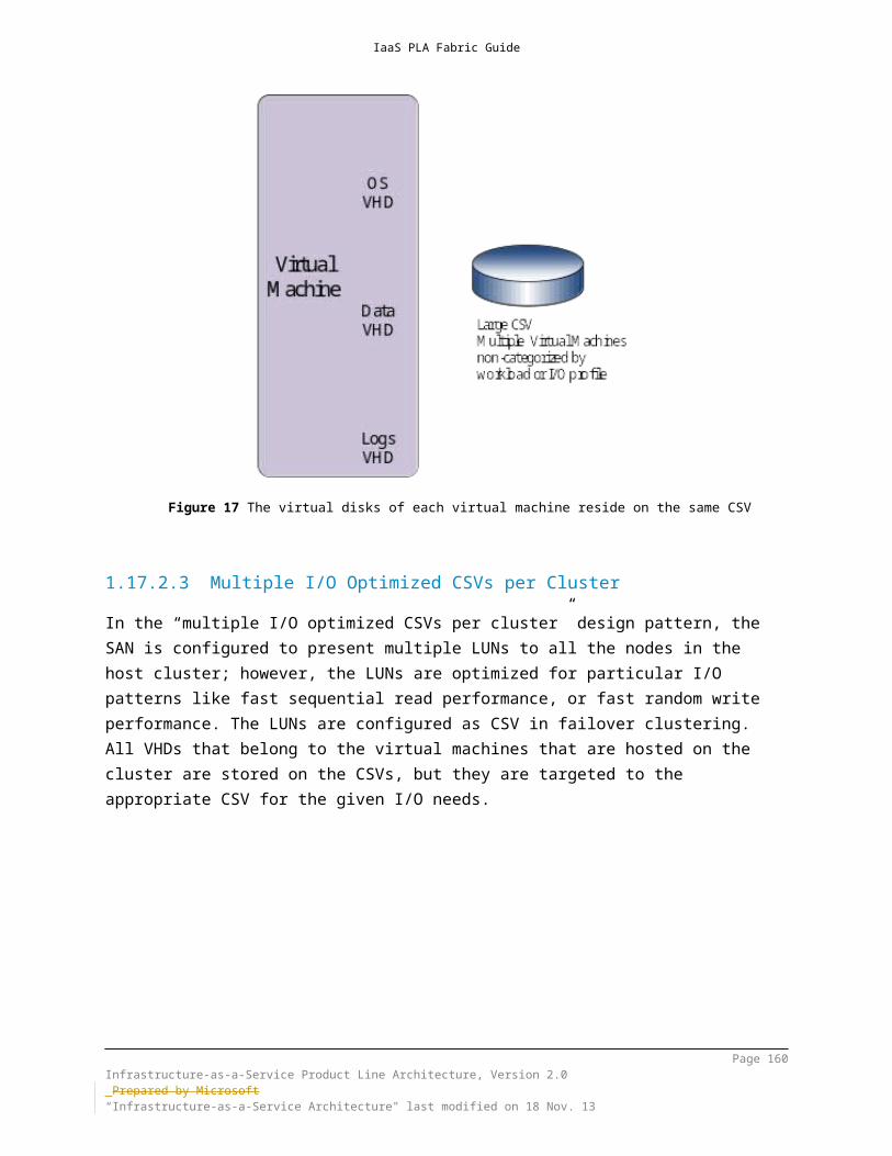
IaaS PLA Fabric Guide
Design Guidance
http://technet.microsoft.com/library/hh831389.aspx http://blogs.msdn.com/b/virtual_pc_guy/archive/2013/10/14/figuring-out-your-
numa-topology-with-hyper-v.aspx
10.1.9 Dynamic MemoryDynamic Memory, which was introduced in Windows Server 2008 R2 SP1, helps you use physical memory more efficiently. By using Dynamic Memory, Hyper-V treats memory as a shared resource that can be automatically reallocated among running virtual machines. Dynamic Memory adjusts the amount of memory that is available to a virtual machine, based on changes in memory demand and on the values that you specify.In Windows Server 2012 R2, Dynamic Memory has a new configuration item called “minimum memory.” Minimum memory lets Hyper-V reclaim the unused memory from the virtual machines. This can result in increased virtual machine consolidation numbers, especially in VDI environments.Windows Server 2012 also introduces Hyper-V Smart Paging for robust restart of virtual machines. Although minimum memory increases virtual machine consolidation numbers, it also brings a challenge. If a virtual machine has a smaller amount of memory than its startup memory and it is restarted, Hyper-V needs additional memory to restart the virtual machine. Because of host memory pressure or the states of the virtual machines, Hyper-V might not always have additional memory available, which can cause sporadic virtual machine restart failures in customer environments. In Windows Server 2012, Hyper-V Smart Paging is used to bridge the memory gap between minimum memory and startup memory and to let virtual machines restart more reliably.
Page 160Infrastructure-as-a-Service Product Line Architecture, Version 2.0 Prepared by Microsoft“Infrastructure-as-a-Service Architecture" last modified on 4 Dec. 13

IaaS PLA Fabric Guide
In Windows Server 2012 R2 Dynamic Memory for Hyper-V allows for the following: Configuration of a lower minimum memory for virtual machines and have an
effective restart experience. Increasing the maximum memory and decreasing the minimum memory on
virtual machines that are running. Also you can increase the memory buffer.
Design GuidanceIt is recommended to use dynamic memory with specific values as configuration changes can be made to Dynamic Memory when the virtual machine is running, however this is not the case when static memory settings are used. Ensure that virtual machines are running a guest operating system that provides support for the Dynamic Memory feature. Also consult with applications vendors on Dynamic Memory compatibility. Complicated database applications like SQL Server or Exchange Server implement their own memory managers. Specific guidance exists on dynamic memory compatibility for such applications. .NET applications are generally known to consume as many memory as possible, however this is not always the case.References: http://technet.microsoft.com/en-us/library/hh831766.aspx
10.1.10 Hyper-V ReplicaYou can use failover clustering to create high availability virtual machines, but this does not protect businesses from outage of an entire data center without the use of hardware-based SAN replication across data centers. Hyper-V Replica fills an important need by providing an affordable failure recovery solution from an entire site, down to a single virtual machine. It provides asynchronous, unlimited replication of your virtual machines over a network link from one Hyper-V host at a primary site to another Hyper-V host at a replica site, without relying on storage arrays or other software replication technologies. Windows Server 2012 R2 Hyper-V Replica supports replication between a source and target Hyper-V server and can further support extending replication from the target server to a third server (extended replication). The servers can be physically co-located or geographically separated.Hyper-V Replica tracks the write operations on the primary virtual machine and replicates these changes to the replica server efficiently over a WAN. The network connection between servers using the HTTP or HTTPS protocol and supports integrated and certificate-based authentication. Connections configured to use integrated authentication are not encrypted. For an encrypted connection, use certificate-based authentication. Windows Server 2012 R2 Hyper-V Replica provides support for replication frequencies of 15 minutes, 5 minutes or 30 seconds. In Windows Server 2012 R2, recovery points can be configured to be accessed up to
Page 161Infrastructure-as-a-Service Product Line Architecture, Version 2.0 Prepared by Microsoft“Infrastructure-as-a-Service Architecture" last modified on 4 Dec. 13
IaaS PLA Fabric Guide
24 hours old where Windows Server 2012 allowed access to recovery points up to 15 hours old. Hyper-V Replica is closely integrated with Windows failover clustering and provides seamless replication across migration scenarios in the primary and replica servers. PLA Rule Set – All Patterns
Mandatory: Support for Hyper-V Replica is mandatory. Additional OEM DR solutions can also be enabled, provided they do not prohibit Hyper-V Replica.
Design GuidanceFrom the perspective of the storage of the primary (source) server, changes are tracked against the defined replication interval and then sent on the wire while the next sets of changes are tracked. In a correctly provisioned environment, one should expect the primary storage to take up twice the churn (per replicating virtual hard disk).From the perspective of the storage on the replica (destination) server, the IOPS impact is expected to be 3-5 times the write IOPS on the primary. This is in part due to the IO required to receive the changes, un-compress, write temporarily to disk, read from disk and write to the VHD.From the perspective of replica disk growth, it is important to account for space for the base disk. Every recovery point is stored as a recovery snapshot whose storage requirements are dependent on the read/write pattern of the workload. Internal tests have revealed a wide range between 2-20% of the disk.From the perspective of replica disk IOPS, the VHDX virtual hard disk format is better due to the optimization of the differencing disk format, allowing for more efficient growth and zeroing out of sectors.References:
http://technet.microsoft.com/library/jj134172.aspx http://technet.microsoft.com/library/hh831716.aspx
10.1.11 Resource MeteringWindows Server 2012 R2 Hyper-V supports resource metering, which is a technology that helps you track historical data on the use of virtual machines and gain insight into the resource use of specific servers. In Windows Server 2012 R2 resource metering provides accountability for CPU, Memory and Network and Storage IOPS. You can use this data to perform capacity planning, monitor consumption by different business units or customers, or capture data that is necessary to help redistribute the costs of running a workload. You could also use
Page 162Infrastructure-as-a-Service Product Line Architecture, Version 2.0 Prepared by Microsoft“Infrastructure-as-a-Service Architecture" last modified on 4 Dec. 13
IaaS PLA Fabric Guide
the information that this feature provides to help build a billing solution, so that you can charge customers of your hosting services appropriately for their usage of resources.
PLA Rule Set – All Patterns
Optional: Resource metering is optional.
Design GuidanceMovement of virtual machines between Hyper-V hosts (such as through live, offline, or storage migration) does not affect the data collection process.Having resource metering enabled and just capturing utilization data per your billing cycle has no noticeable performance impact. There will be some negligible disk and CPU activity as data is written to the configuration file.Enabling, configuring and measuring resource metering can be performed through PowerShell using the following commands:
Get-VM –ComputerName <Name> | Enable-VMResourceMetering
Set-VMHost –ComputerName <Name> -ResourceMeteringSaveInterval <TimeSpan> { 00:00:00 }
Get-VM –ComputerName <Name> | Measure-VM
In Windows Server 2012, resource pools can be created to act as an intermediary layer between the virtual machine and the hardware. In previous versions of Windows Server Hyper-V these pools existed but were limited to the primordial pools created within the OS and did not support assignment of host resources to pool instances. Windows Server 2012 allows for a hierarchy of resource pools may be supported in order to partition or provide varying administrative controls over a set of host resources. In these advanced configurations resource metering and chargeback analysis can occur within a given resource pool just as it can within the base resource pools References:
http://technet.microsoft.com/library/hh831661.aspx http://blogs.technet.com/b/virtualization/archive/2012/08/16/introduction-to-
resource-metering.aspx, http://code.msdn.microsoft.com/windowsdesktop/Hyper-V-resource-pool-
df906d95
Page 163Infrastructure-as-a-Service Product Line Architecture, Version 2.0 Prepared by Microsoft“Infrastructure-as-a-Service Architecture" last modified on 4 Dec. 13
IaaS PLA Fabric Guide
10.1.12 Enhanced Session ModeEnhanced session mode allows redirection of devices, clipboard and printers from clients using the Virtual Machine Connection tool. The enhanced session mode connection uses a Remote Desktop Connection session via the virtual machine bus (VMBus) which does not require an active network connection to the virtual machine as would be required for a traditional Remote Desktop Protocol connection. Enhanced session mode connections provide additional capabilities beyond simple mouse, keyboard and monitor redirection and supports capabilities typically associated with Remote Desktop Protocol session such as display configuration, audio devices, printers, clipboards, smart card, USB devices, drives and supported Plug and Play devices. Enhanced session mode requires a supported guest operating system such as Windows Server 2012 R2 and Windows 8.1 and may require additional configuration inside the virtual machine. By default Enhanced session mode is disabled in Windows Server 2012 R2, but can be enabled through the Hyper-V Server settings.
PLA Rule Set – All Patterns
Optional: Enabling enhanced session mode is recommended.
Design GuidanceWhen Use enhanced session mode is enabled, device redirection will take place when the following conditions are met:
Allow enhanced session mode is enabled on the server running Hyper-V. The virtual machine is running an operating system which supports enhanced session
mode. The Remote Desktop Service is running in the virtual machine.
Enhanced session mode can be enabled through the following Hyper-V Server setting:
Page 164Infrastructure-as-a-Service Product Line Architecture, Version 2.0 Prepared by Microsoft“Infrastructure-as-a-Service Architecture" last modified on 4 Dec. 13

IaaS PLA Fabric Guide
Design Guidance
Basic Session Mode (current through VMConnect):
Enhanced Session Mode:
Page 165Infrastructure-as-a-Service Product Line Architecture, Version 2.0 Prepared by Microsoft“Infrastructure-as-a-Service Architecture" last modified on 4 Dec. 13

IaaS PLA Fabric Guide
Design Guidance
References: http://technet.microsoft.com/library/dn282274.aspx
10.2 Hyper-V Guest Virtual Machine DesignStandardization is a key tenet of private cloud architectures and virtual machines. A standardized collection of virtual machine templates can drive predictable performance and greatly improve capacity planning capabilities. As an example, the following table illustrates the composition of a basic virtual machine template library. Note, this should not replace proper template planning using System Center Virtual Machine Manager.
Template Specifications Network Operating system
Unit cost
Template 1—Small
2 vCPU, 4 GB memory,
50 GB disk
VLAN 20 Windows Server 2008 R2
1
Template 2—Medium
8 vCPU, 16 GB memory, 100 GB disk
VLAN 20 Windows Server 2012 R2
2
Template 3—X-Large
24 vCPU, 64 GB memory, 200 GB disk
VLAN 20 Windows Server 2012 R2
4
Page 166Infrastructure-as-a-Service Product Line Architecture, Version 2.0 Prepared by Microsoft“Infrastructure-as-a-Service Architecture" last modified on 4 Dec. 13

IaaS PLA Fabric Guide
Table 11 Template specification
10.2.1 Virtual Machine Storage10.2.1.1 Dynamically Expanding DisksDynamically expanding VHDs provide storage capacity as needed to store data. The size of the VHD file is small when the disk is created and grows as data is added to the disk. The size of the VHD file does not shrink automatically when data is deleted from the virtual hard disk; however, you can use the Edit Virtual Hard Disk Wizard to make the disk more compact and decrease the file size after data is deleted.
10.2.1.2 Fixed-Size DisksFixed-size VHDs provide storage capacity by using a VHDX file that is in the size that is specified for the virtual hard disk when the disk is created. The size of the VHDX file remains fixed, regardless of the amount of data that is stored. However, you can use the Edit Virtual Hard Disk Wizard to increase the size of the VHDX, which in turn increases the size of the VHDX file. By allocating the full capacity at the time of creation, fragmentation at the host level is not an issue. (Fragmentation inside the VHDX itself must be managed within the guest.)
10.2.1.3 Differencing DisksDifferencing VHDs provide storage to help you make changes to a parent VHD without changing the disk. The size of the VHD file for a differencing disk grows as changes are stored to the disk.
10.2.1.4 Pass-Through DisksWhile not recommended, pass-through disks allows Hyper-V virtual machine guests directly access local disks or SAN LUNs that are attached to the physical server, without requiring the volume to be presented to the host server. The virtual machine guest accesses the disk directly (by utilizing the GUID of the disk) without having to utilize the file system of the host. Given that the performance difference between fixed-disk and pass-through disks is now negligible, the decision is based on manageability. For instance, a VHDX is hardly portable if the data on the volume will be very large (hundreds of gigabytes), given the extreme amounts of time it takes to copy. For a backup scheme with pass-through disks the data can be backed up only from within the guest.When you are utilizing pass-through disks, no VHDX file is created, because the LUN is used directly by the guest. Because there is no VHDX file, there is no dynamic sizing or snapshot capability. These disks are not subject to migration with the virtual machine and are only applicable to standalone Hyper-V configurations, and
Page 167Infrastructure-as-a-Service Product Line Architecture, Version 2.0 Prepared by Microsoft“Infrastructure-as-a-Service Architecture" last modified on 4 Dec. 13

IaaS PLA Fabric Guide
therefore are not recommended for common, large scale Hyper-V configurations. In many cases virtual fibre channel capabilities supersede the need to leverage pass-through disks when working with fibre channel SANs.
10.2.1.5 In-guest iSCSI InitiatorHyper-V can also utilize iSCSI storage by directly connecting to iSCSI LUNs that are utilizing the virtual network adapters of the guest. This is mainly used for access to large volumes on SANs to which the Hyper-V host itself is not connected or for guest clustering. Guests cannot boot from iSCSI LUNs that are accessed through the virtual network adapters without utilizing the iSCSI initiator.
10.2.1.6 Storage Quality of ServiceWindows Server 2012 R2 Storage quality of service (QoS) provides the ability to specify a maximum input/output operations per second (IOPS) value for a virtual hard disk in Hyper-V, protecting tenants in a multitenant Hyper-V infrastructure from consuming excessive storage resources that may impact other tenants (often referred to as a “noisy neighbor”). Maximum and minimum values are specified in terms of normalized IOPS where every 8 K of data is counted as an I/O. Administrators can configure Storage QoS for a given virtual hard disk attached to a virtual machine. Configurations include setting both maximum and minimum values for the IOPS given virtual hard disk. Maximum values are enforced while minimum values generate administrative notifications.
Design GuidanceDynamically expanding disks are also a viable option for production use; however, they carry other risks such as storage oversubscription and fragmentation, so use with caution and monitor virtual to physical storage utilization.Differencing disks are not recommended for production server workloads but can be used for VDI workloads.Use pass-through disks only in cases in which absolute maximum performance is required and the loss of features such as snapshots and portability is acceptable. Since the performance difference between pass-through and fixed-disks is minimal, there should be very few scenarios in which pass-through disks are required.For in-guest iSCSI, make sure that a separate virtual network is utilized for access to the iSCSI storage to obtain acceptable performance. If the virtual machine iSCSI network is shared with Ethernet traffic, utilize QoS to provide performance assurances to the different networks. Consider using jumbo frames within the guest to improve iSCSI performance.Limits and Reserves are configured in terms of number of IOPS. Any virtual hard disk that does not have a minimum or maximum IOPS limit defined defaults to 0. Valid range [0 - 1,000,000,000].In Windows Server 2012 R2 PowerShell MaximumIOPS and MinimumIOPS are settings on the VMHardDiskDrive object. Storage QoS can be configured using the following commands:
Page 168Infrastructure-as-a-Service Product Line Architecture, Version 2.0 Prepared by Microsoft“Infrastructure-as-a-Service Architecture" last modified on 4 Dec. 13

IaaS PLA Fabric Guide
Design GuidanceAdd-VMHardDiskDrive -vmname VM1 -path 'D:\VM1.vhdx' -MinimumIOPS 2000 –MaximumIOPS 700000
Add-VMHardDiskDrive -vmname VM1 -path 'D:\VM1.vhdx' -MinimumIOPS 3000
Get-VMHardDiskDrive -vmname VM1 | ?{$_.path -eq 'D:\VM1.vhdx'} | Set-VMHardDiskDrive -MinimumIOPS 10000 -MaximumIOPS 100000
Event ID 32930 is raised if the IOPSMinimum value is not met, however once throughput values are met Event ID 32931 is generated.
References: http://technet.microsoft.com/library/hh831446.aspx http://blogs.technet.com/b/meamcs/archive/2013/10/03/windows-server-
2012-r2-preview-hyper-v-shared-vhdx-and-storage-qos.aspx http://technet.microsoft.com/library/dn282281.aspx
10.2.2 Virtual Machine NetworkingHyper-V guests support two types of virtual switch adapters: synthetic and emulated. Synthetic adapters make use of the Hyper-V VMBus architecture, and they are the high-performance, native devices. Synthetic devices require that the Hyper-V integration services be installed within the guest. Emulated adapters are available to all guests, even if integration services are not available. They perform much more slowly and should be used only if synthetic devices are unavailable. You can create many virtual networks on the server running Hyper-V to provide a variety of communications channels. For example, you can create virtual switches to provide the following:
Communications between virtual machines only. This type of virtual network is called a private network.
Communications between the host server and virtual machines. This type of virtual network is called an internal network.
Communications between a virtual machine and a physical network by creating an association to a physical network adapter on the host server. This type of virtual network is called an external network.
PLA Rule Set – All Patterns
Recommended: When possible, use synthetic virtual network adapters. Use Generation 2 virtual machines or emulated network adapters in
Generation 1 virtual machines when the guest must pre-boot execution environment (PXE) boot.
Page 169Infrastructure-as-a-Service Product Line Architecture, Version 2.0 Prepared by Microsoft“Infrastructure-as-a-Service Architecture" last modified on 4 Dec. 13

IaaS PLA Fabric Guide
For the private cloud scenario, the recommendation is to use one or more external networks per virtual machine, and segregate the networks with VLANs and other network security infrastructure, as needed.
Design GuidanceWhile listed here, note that Private and Internal network types are not supported under Virtual Machine Manager networking.
10.2.3 Virtual Machine Compute10.2.3.1 Virtual Machine GenerationWindows Server 2012 R2 Hyper-V virtual machine generation is a new feature which determines the virtual hardware and functionality that is presented to the virtual machine. Windows Server 2012 R2 Hyper-V supports two virtual machine generation types: generation 1 and generation 2. Generation 1 virtual machines represent the same virtual hardware and functionality available in previous versions of Hyper-V, which provides BIOS-based firmware and a series of emulated devices. Generation 2 VMs provide the platform capability to support advanced virtual features and deprecates legacy BIOS and emulators from virtual machines which can potentially increase security and performance. Generation 2 virtual machines provides a simplified virtual hardware model including Unified Extensible Firmware Interface (UEFI) firmware. Several legacy devices are removed from generation 2 virtual machines. Generation 2 virtual machines have a simplified virtual hardware model provided through the VMBus as synthetic devices (networking, storage, video, graphic) supporting Secure Boot, boot from a SCSI virtual hard disk or virtual DVD, PXE boot by using a standard network adapter as well as supporting Unified Extensible Firmware Interface (UEFI) firmware.Additionally, several legacy devices are removed from generation 2 virtual machines including IDE drives and legacy network adapter support. Generation 2 virtual machines are only supported on the Windows Server 2012, Windows Server 2012 R2, and Windows 8 and 8.1 (64-bit versions).
PLA Rule Set – All Patterns
Optional: The use of Generation 2 virtual machines is optional, however this is recommended for all new virtual machines running compatible Guest operating systems.
Page 170Infrastructure-as-a-Service Product Line Architecture, Version 2.0 Prepared by Microsoft“Infrastructure-as-a-Service Architecture" last modified on 4 Dec. 13
IaaS PLA Fabric Guide
Design GuidanceReferences: http://technet.microsoft.com/library/dn282285.aspx
10.2.3.2 Virtual Processors and Fabric DensityProviding sufficient CPU density is a matter of identifying the required number of physical cores to serve as virtual processors for the fabric. When performing capacity planning, it is proper to plan against cores and not hyperthreads or symmetric multithreads (SMT). Although SMT can boost performance (approximately 10 to 20 percent), SMT threads are not equivalent to cores.A minimum of two CPU sockets is required for product line architecture (PLA) pattern configurations. Combined with a minimum 6-core CPU model, 12 physical cores per scale unit host are available to the virtualization layer of the fabric. Most modern server class processors support a minimum of six cores, with some families supporting up to 10 cores. Given the average virtual machine requirement of two virtual CPUs (vCPUs), a two-socket server that has midrange six-core CPUs provides 12 logical CPUs. This provides a potential density of between 96 and 192 virtual CPUs on a single host.As an example, table 13 outlines the estimated virtual machine density based on a two-socket, six-core processor that uses a pre-determined processor ratio. Note, however, that CPU ration assumptions are highly dependent on workload analysis and planning and should be factored into any calculations. For this example, the processor ratio would have been defined through workload testing and an estimation of potential density, and required reserve capacity, could then be calculated.
Nodes
Sockets
Cores
Total Cores
Logical CPU
pCPU/vCPU Ratio
Available vCPU
Average vCPUWorkload
Estimated Raw Virtual Machine Density
Virtual Machine Density Less Reserve Capacity
1 2 6 12 12 8 96 2 48 N/A
4 2 6 12 48 8 384 2 192 144
8 2 6 12 96 8 768 2 384 336
12 2 6 12 144 8 1152 2 576 528
16 2 6 12 192 8 1536 2 768 720
Page 171Infrastructure-as-a-Service Product Line Architecture, Version 2.0 Prepared by Microsoft“Infrastructure-as-a-Service Architecture" last modified on 4 Dec. 13

IaaS PLA Fabric Guide
Nodes
Sockets
Cores
Total Cores
Logical CPU
pCPU/vCPU Ratio
Available vCPU
Average vCPUWorkload
Estimated Raw Virtual Machine Density
Virtual Machine Density Less Reserve Capacity
32 2 6 12 384 8 3072 2 1536 1344
64 2 6 12 768 8 6144 2 3072 2688
1 2 8 16 16 8 128 2 64 N/A
4 2 8 16 64 8 512 2 256 192
8 2 8 16 128 8 1024 2 512 448
12 2 8 16 192 8 1536 2 768 704
16 2 8 16 256 8 2048 2 1024 960
32 2 8 16 512 8 4096 2 2048 1792
64 2 8 16 1024 8 8192 2 4096 3584
1 2 10 20 20 8 160 2 80 N/A
4 2 10 20 80 8 640 2 320 240
8 2 10 20 160 8 1280 2 640 560
12 2 10 20 240 8 1920 2 960 880
16 2 10 20 320 8 2560 2 1280 1200
32 2 10 20 640 8 5120 2 2560 2240
64 2 10 20 1280 8 10240 2 5120 4480
Table 12 Example virtual machine density chart
Note that there are also supported numbers of virtual processors in a specific Hyper-V guest operating system. For more information, please see Hyper-V Overview on Microsoft TechNet (http://technet.microsoft.com/library/hh831531.aspx).
Design GuidancePreviously, Windows Server 2008 R2 SP1 supported CPU ratios of 8:1 for server workloads and 12:1 for client workloads; however, vCPU ratio is now dependent on the supportability
Page 172Infrastructure-as-a-Service Product Line Architecture, Version 2.0 Prepared by Microsoft“Infrastructure-as-a-Service Architecture" last modified on 4 Dec. 13

IaaS PLA Fabric Guide
Design Guidancestatements of the workloads that are running on the fabric infrastructure. Given that Windows Server 2012 R2 no longer has support limitations on virtual or physical processor ratios, you should follow workload analysis and supportability requirements to determine the supported physical CPU (pCPU) and vCPU limits.Workload vCPU limits are outlined by OS. These can be found at the Hyper-V Overview reference listed below in the “Software requirements (for supported guest operating systems)” section. At the time of writing, scalability for each operating system can be found in the Software requirements for supported guest operating systems section of the Hyper-V Overview TechNet article (http://technet.microsoft.com/library/hh831531.aspx).References: http://technet.microsoft.com/library/hh831531
10.2.4 Linux-Based Virtual MachinesLinux virtual machine support in Windows Server 2012 R2 and System Center 2012 R2 is focused at providing more parity with the Windows based virtual machines. The Linux Integration Services (LIS) are now part of the Linux Kernel version 3.x.9 and higher. This means that it is no longer a requirement to install LIS as part of the image build process. Information on Linux kernels can be found at https://kernel.org Linux virtual machines can natively take advantage of the following:
Dynamic Memory. Linux VMs are now able to take advantage of the increased density and resource usage efficiency of Dynamic Memory. Memory ballooning and hot add are supported.
Support for online snapshots. Linux VMs can be backed up live, with consistent memory and file systems. Note that this is not app aware consistency similar to what would be achieved with Volume Snapshot Services in Windows.
Online resizing of VHDs. Linux VMs can have attached iSCSI VHD(x)s expanded while the VM is running.
Synthetic 2D frame buffer driver. Improves display performance within graphical apps.
This can be performed on Windows Server 2012 or Windows Server 2012 R2 Hyper-V.
PLA Rule Set – All Patterns
Page 173Infrastructure-as-a-Service Product Line Architecture, Version 2.0 Prepared by Microsoft“Infrastructure-as-a-Service Architecture" last modified on 4 Dec. 13
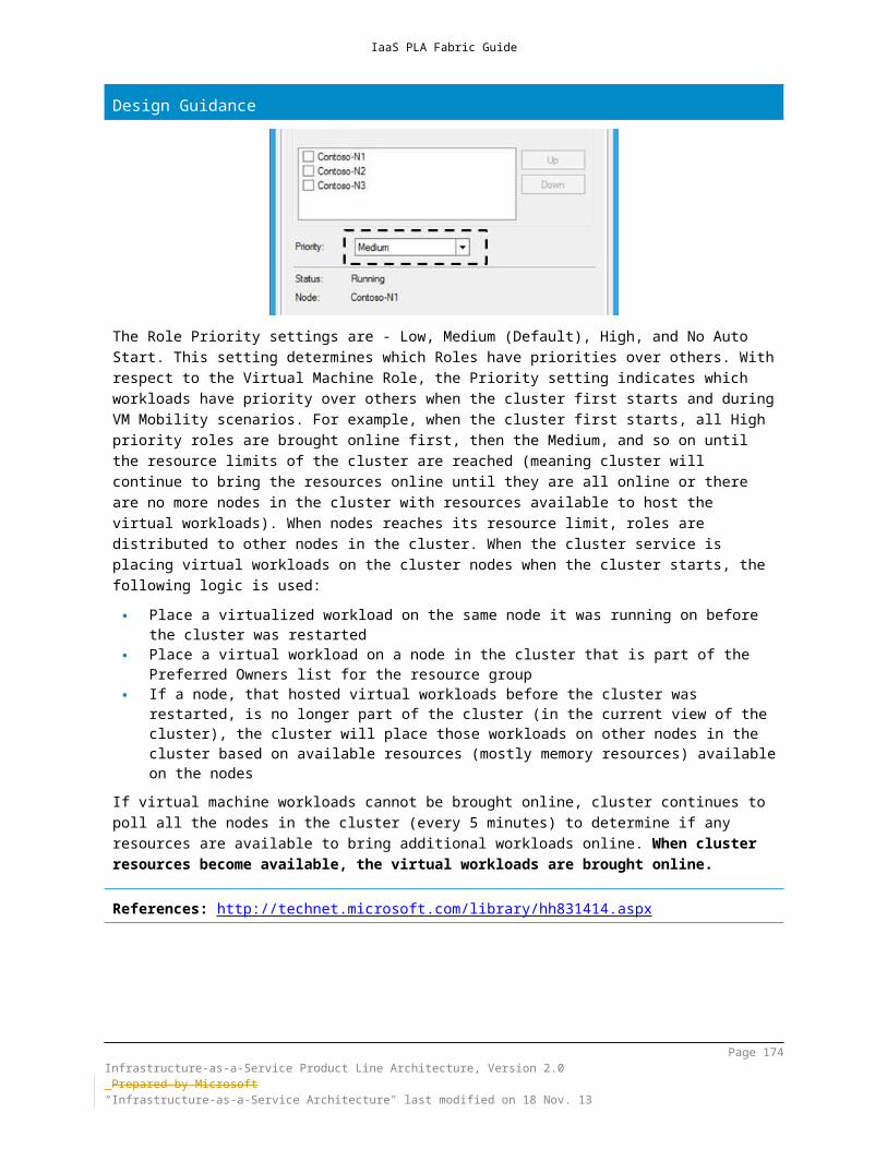
IaaS PLA Fabric Guide
Mandatory: Support for Linux-based virtual machines is included when using the proper Linux distributions.
Design GuidanceWhen building a Linux VM for deploying with VMM 2012 R2 you must install the Linux VMM agent prior to copying the VHDx into the VMM library or creating a templateOnline backup of Linux virtual machines may require that no user is interactively logged onto the VM at the time of backupVerify that the Linux distribution that you are currently using has the proper kernel for the Linux Integration Services to be included. Without the integrated LIS components, the advanced features listed above will not be available.Inside the Linux VM, run cat /proc/version and verify the Linux version is version 3.x.9 or higher.Inside the Linux VM, run dmesg | grep Hyper-V and verify the vmbus version is 2.4 or higher.To verify dynamic memory, inside the Linux VM, run dmesg | grep Memory and verify the memory usage matches the data in the Hyper-V consoleTo support online backups for Linux machines, the VHDx has to be stored on local storage and cannot be stored on a remote SMB share and the backup location must be on a different drive than the original VHDx
References: http://blogs.technet.com/b/virtualization/archive/2013/07/24/enabling-linux-
support-on-windows-server-2012-r2-hyper-v.aspx http://technet.microsoft.com/library/jj860438.aspx
10.2.5 Automatic Virtual Machine ActivationAutomatic Virtual Machine Activation (AVMA) is a new feature in Windows Server 2012 R2 that makes it easier for service providers and large IT organizations to use the licensing advantages accorded by Windows Server Datacenter. Specifically, Windows Server Datacenter provides unlimited virtual machine instances of Windows Server for a licensed system. This allows our customers to simply license the server, provide as much resources as desired, and run as many instances of Windows Server as the system can deliver. With automatic virtual machine activation, Windows Server 2012 R2 guests will automatically activate themselves when running on a Windows Server 2012 R2 Datacenter host making it easier and faster to deploy cloud solutions based on Windows Server 2012 R2 Datacenter.Requirements:
Page 174Infrastructure-as-a-Service Product Line Architecture, Version 2.0 Prepared by Microsoft“Infrastructure-as-a-Service Architecture" last modified on 4 Dec. 13

IaaS PLA Fabric Guide
Automatic Virtual Machine Activation (AVMA) requires that the host operating system (running on the bare metal) is Windows Server 2012 R2 Datacenter with Hyper-V and the supported guest operating systems (running within the virtual machine) are:
Windows Server 2012 R2 Standard Windows Server 2012 R2 Datacenter Windows Server 2012 R2 Essentials
PLA Rule Set – All Patterns
Recommended: Enabling Automatic Virtual Machine Activation is recommended.
Design GuidanceFor AVMA support, a complete list of Microsoft Server 2012 R2 SKUs and their compatibility is provided:
Windows SKU - AVMA Guest Microsoft Hyper-V Server - No (1) Windows Server Foundation – No (1) Windows Server Essentials - Yes Windows Server Standard - Yes Windows Server Standard Eval – No (2) Windows Server Datacenter - Yes Windows Server Datacenter Eval – No (2) Windows Storage Server Standard – No (3) Windows Storage Server Standard Eval – No (2) Windows Storage Server Workgroup – No (1) Windows Storage Server Workgroup Eval – No (2) Windows MultiPoint Server – No
Legend:1 = this product is not a supported guest in a Hyper-V virtual machine and thus AVMA isn’t appropriate2 = this product is an evaluation version and thus isn’t activated using AVMA3 = this product is an OEM specific SKU and downgrade rights do not apply and thus AVMA isn’t appropriate
References: http://technet.microsoft.com/library/dn303421.aspx http://www.microsoft.com/licensing/activation/existing-customers/product-
activation.aspx
Page 175Infrastructure-as-a-Service Product Line Architecture, Version 2.0 Prepared by Microsoft“Infrastructure-as-a-Service Architecture" last modified on 4 Dec. 13

IaaS PLA Fabric Guide
Page 176Infrastructure-as-a-Service Product Line Architecture, Version 2.0 Prepared by Microsoft“Infrastructure-as-a-Service Architecture" last modified on 4 Dec. 13
IaaS PLA Fabric Guide
11 Windows Azure IaaS ArchitectureWindows Azure is the Microsoft platform for the public cloud. You can use this platform in many different ways. For instance, you can use Windows Azure to build a web application that runs and stores its data in Microsoft data centers. You can use Windows Azure just to store data, with the applications that use this data running on-premises (that is, outside the public cloud). You can use Windows Azure to create virtual machines for development and test or to run production deployments of SharePoint and other applications. You can use Windows Azure to build massively scalable applications that have thousands or millions of users. A detailed description of the Windows Azure services can be found at this link: http://www.windowsazure.com/en-us/services/Windows Azure provides public-cloud platform as a service (PaaS) and infrastructure as a service (IaaS) with the addition of Windows Azure virtual machines. With the IaaS capability, Windows Azure becomes a core part of the Cloud OS vision. It is critical to have a deep understanding of Windows Azure services and architecture to be able to create hybrid cloud architectures.
Figure 22 Windows Azure http://www.microsoft.com/en-us/download/confirmation.aspx?id=35473
Page 177Infrastructure-as-a-Service Product Line Architecture, Version 2.0 Prepared by Microsoft“Infrastructure-as-a-Service Architecture" last modified on 4 Dec. 13

IaaS PLA Fabric Guide
11.1 Windows Azure Services11.1.1 Windows Azure Compute ServicesVirtual MachinesWindows Azure Virtual Machines enable you to deploy a Windows Server or Linux image in the cloud. You can select images from a gallery or bring your own customized images.Cloud ServicesWindows Azure Cloud Services remove the need to manage server infrastructure. With Web and Worker roles, they enable you to quickly build, deploy and manage modern applications.Web SitesWindows Azure Web Sites enables you to deploy web applications on a scalable and reliable cloud infrastructure. You can quickly scale up and out or even scale automatically to meet your application needs.Mobile Services Windows Azure Mobile Services provides a scalable cloud backend for building Windows Store, Windows Phone, Apple iOS, Android, and HTML/JavaScript applications. Store data in the cloud, authenticate users, and send push notifications to your application within minutes.
11.1.2 Windows Azure Data ServicesStorageWindows Azure Storage offers non-relational data storage including Blob, Table, Queue and Drive storage.SQL DatabaseWindows Azure SQL Database is a relational database service that enables you to rapidly create, extend, and scale relational applications into the cloud.SQL ReportingWindows Azure SQL Reporting allows you to build easily accessible reporting capabilities into your Windows Azure application. You can get up and running in hours versus days at a lower upfront cost without the hassle of maintaining your own reporting infrastructure.Backup
Page 178Infrastructure-as-a-Service Product Line Architecture, Version 2.0 Prepared by Microsoft“Infrastructure-as-a-Service Architecture" last modified on 4 Dec. 13

IaaS PLA Fabric Guide
Windows Azure Backup manages cloud backups through familiar tools in Windows Server 2012, Windows Server 2012 Essentials, or System Center 2012 Data Protection Manager.CacheWindows Azure Cache is a distributed, in-memory, scalable solution that enables you to build highly scalable and responsive applications by providing super-fast access to data.HDInsightWindows Azure HDInsight Service is a Hadoop-based service that brings an Apache Hadoop solution to the cloud. Gain full value of Big Data with a cloud-based data platform that manages data of any type and any size.Hyper-V Recovery ManagerHyper-V Recovery Manager helps to protect your important services by coordinating the replication and recovery of System Center 2012 private clouds at a secondary location.
11.1.3 Windows Azure Network ServicesVirtual NetworkWindows Azure Virtual Network enables you to create Virtual Private Networks (VPN) within Windows Azure and securely link these with on-premises IT infrastructure.Traffic Manager Windows Azure Traffic Manager allows you to load balance incoming traffic across multiple hosted Windows Azure services whether they’re running in the same datacenter or across different datacenters around the world.
11.1.4 Windows Azure Application ServicesActive DirectoryWindows Azure Active Directory provides identity management and access control capabilities for your cloud applications. You can synchronize your on-premises identities and enable single sign-on to simplify user access to cloud applications.Multi-Factor AuthenticationWindows Azure Multi-Factor Authentication helps prevent unauthorized access to on-premises and cloud applications by providing an additional layer of authentication. Follow organizational security and compliance standards while also addressing user demand for convenient access.
Page 179Infrastructure-as-a-Service Product Line Architecture, Version 2.0 Prepared by Microsoft“Infrastructure-as-a-Service Architecture" last modified on 4 Dec. 13

IaaS PLA Fabric Guide
Service BusWindows Azure Service Bus is a messaging infrastructure that sits between applications allowing them to exchange messages for improved scale and resiliencyNotification HubsNotification Hubs provide a highly scalable, cross-platform push notification infrastructure that enables you to either broadcast push notifications to millions of users at once or tailor notifications to individual users.BizTalk ServicesWindows Azure BizTalk Services is a powerful and extensible cloud-based integration service that provides Business-to-Business (B2B) and Enterprise Application Integration (EAI) capabilities for delivering cloud and hybrid integration solutions.Media ServicesWindows Azure Media Services offer cloud-based media solutions from many existing technologies including ingest, encoding, format conversion, content protection and both on-demand and live streaming capabilities.Windows Azure provides a robust set of training and documentation in the Windows Azure Training kit:
Windows Azure Training Kit website available at the following Link. Windows Azure Training Kit presentations are available at the following Link. Windows Azure Training Kit demos are available at the following Link.
11.2 Windows Azure Accounts and Subscriptionshttp://msdn.microsoft.com/en-us/library/windowsazure/hh531793.aspxA Windows Azure subscription grants you access to Windows Azure services and to the Windows Azure Management Portal. The terms of the Windows Azure account, which is acquired through the Windows Azure Account Portal, determine the scope of activities that you can perform in the Management Portal and describe the limits on available storage, network, and compute resources.In the Management Portal, you see only the services that are created by using a subscription for which you are an administrator. The billing account sets the number of compute units (virtual machines), hosted services, and storage that can be used. You can view usage information for a service by clicking the service in the Management Portal.
Page 180Infrastructure-as-a-Service Product Line Architecture, Version 2.0 Prepared by Microsoft“Infrastructure-as-a-Service Architecture" last modified on 4 Dec. 13

IaaS PLA Fabric Guide
A Windows Azure subscription has two aspects: The Windows Azure account, through which resource usage is reported and
services are billed. Each account is identified by a Windows Live ID or corporate email account and is associated with at least one subscription. The account owner monitors usage and manages billings through the Windows Azure Account Center.
The subscription itself, which governs access to and use of the Windows Azure subscribed service. The subscription holder uses the Management Portal to manage services.
The account and the subscription can be managed by the same individual or by different individuals or groups. In a corporate enrollment, an account owner might create multiple subscriptions to give members of the technical staff access to services. Because resource usage within an account billing is reported for each subscription, an organization can use subscriptions to track expenses for projects, departments, regional offices, and so forth. In this scenario, the account owner uses the Windows Live ID that is associated with the account to sign in to the Windows Azure Account Center; however, this individual does not have access to the Management Portal unless he or she has created a subscription for him- or herself.Subscriptions that are created through a corporate enrollment are based on credentials that the organization provides. In this scenario, the subscription holder—who uses the services but is not responsible for billings—has access to the Management Portal but not to the Windows Azure Account Center. By contrast, the personal account holder—who performs both duties—can sign in to either portal by using the Windows Live ID that is associated with the account.By default, Windows Azure subscriptions have the following boundaries:
20 storage accounts (soft limit) 200 terabytes (TB) per storage account 50 virtual machines in cloud service 25 PaaS roles in cloud service (soft limit) 20 cloud services per subscription (soft limit) 250 endpoints per cloud service 1,024 virtual machines in a virtual network
11.2.1 Sharing Service Management by Adding Co-AdministratorsWhen a Windows Azure subscription is created, a service administrator is assigned. The default service administrator is the contact person for the subscription. For an individual subscription, this is the person who holds the Windows Live ID that identifies the subscription. The Windows Azure account owner can assign a different service administrator by editing the subscription in the Windows Azure Account Center.
Page 181Infrastructure-as-a-Service Product Line Architecture, Version 2.0 Prepared by Microsoft“Infrastructure-as-a-Service Architecture" last modified on 4 Dec. 13

IaaS PLA Fabric Guide
The service administrator for a subscription has full administrator rights to all Windows Azure services that are subscribed to and all hosted services that are deployed under the subscription. The service administrator also can perform administrative tasks for the subscription itself in the Management Portal. For example, the service administrator can manage storage accounts, affinity groups, and management certificates for the subscription.To share management of hosted services, the service administrator can add co-administrators to the subscription. To be added as a co-administrator, a person needs only a Windows Live ID.Subscription co-administrators share the same administrator rights as the service administrator, with one exception: a co-administrator cannot remove the service administrator from a subscription. Only the Windows Azure account owner can change the service administrator for a subscription, by editing the subscription in the Windows Azure Account Center.Important: Because service administrators and co-administrators in Windows Azure have broad Administrator rights for Windows Azure services, you should assign strong passwords for the Windows Live IDs that identify the subscribers and ensure that the credentials are not shared with unauthorized users.Note that in the Management Portal, the enterprise account owner only has the rights that are granted to any subscription holder. To sign in to the Management Portal, the account owner must be an administrator for a subscription. As soon as an account owner has signed in to the Management Portal, the account owner will be able to see and manage only those hosted services that have been created under subscriptions for which he or she is an administrator. Enterprise account owners cannot see hosted services for subscriptions that they create for other people. To gain visibility into service management under subscriptions that they create, enterprise account owners can ask the subscription holders to add them as co-administrators.
11.2.2 Manage Storage Accounts for Your SubscriptionAdd storage accounts to a Windows Azure subscription to provide access to Windows Azure storage services. The storage account represents the highest level of the namespace for accessing each of the storage-service components: Blob services, Queue services, and Table services. Each storage account provides access to storage in a specific geographic region or affinity group.
11.2.3 Create Affinity Groups to Use with Storage Accounts and Hosted Services
By using affinity groups, you can co-locate storage and hosted services within the same data center. To use an affinity group with a hosted service, assign an affinity
Page 182Infrastructure-as-a-Service Product Line Architecture, Version 2.0 Prepared by Microsoft“Infrastructure-as-a-Service Architecture" last modified on 4 Dec. 13
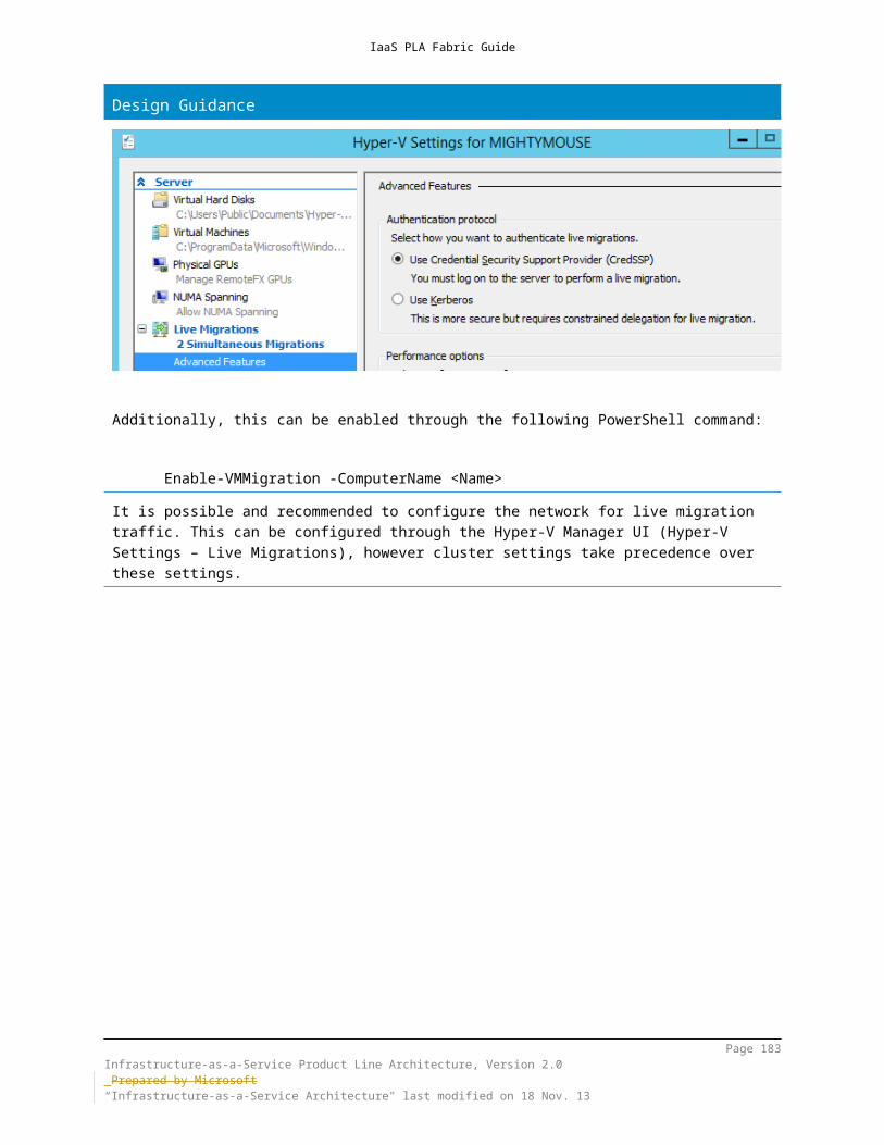
IaaS PLA Fabric Guide
group instead of a geographic region when you create the service. The same option is available when you create a storage account. You cannot change the affinity group for an existing hosted service or storage account.
11.2.4 Add Management Certificates to a Windows Azure Subscription
Management certificates enable client access to Windows Azure resources when using the Windows Azure SDK tools, the Windows Azure Tools for Microsoft Visual Studio, or the Windows Azure Service Management REST API. For example, a management certificate is used to authenticate the user when creating and managing hosted services by using Visual Studio tools or when deploying virtual machine role images by using Windows PowerShell or command-line tools.Management certificates are not required when you work in the Management Portal. In the Management Portal, authentication is performed by using the credentials of the administrator who is performing the operation.
11.2.5 Creating and Managing Windows Azure EnvironmentsGetting started with Windows Azure is relatively straightforward on an individual or small-business basis; however, for enterprise scenarios, proper management and utilization of the preceding constructs is critical from security, administration, and billing standpoints. As an example, the following diagram illustrates a simple scenario in which the Finance department utilizes a combination of billing accounts, Windows Azure subscriptions, Windows Azure Service Administrators, and Windows Azure Co-Administrators to model development, test, and production environments in Windows Azure:
Finance Cost Center – Azure Billing Account
Finance Dev Finance Prod
App1Dev – Azure Subscription
App2 Dev – Azure Subscription
Dev1 – Azure Service Admin
Dev2 – Azure Co-Admin
Dev3 – Azure Service Admin
Dev4 – Azure Co-Admin
App1 Prod – Azure Subscription
App2 Prod – Azure Subscription
Ops1 – Azure Service Admin
Ops2 – Azure Co-Admin
Ops3 – Azure Service Admin
Ops4 – Azure Co-Admin
Test – Azure Subscription
Test1 – Azure Service Admin
Test2 – Azure Co-Admin
Finance Test
During creation of Windows Azure environments for medium and large-size organizations, careful planning of the billing and administration scope is required. The preceding diagram outlines an example of how to model an organization that wants centralized billing but with different organizational units to manage and track its Windows Azure usage.
Page 183Infrastructure-as-a-Service Product Line Architecture, Version 2.0 Prepared by Microsoft“Infrastructure-as-a-Service Architecture" last modified on 4 Dec. 13

IaaS PLA Fabric Guide
It is important to realize that in many areas, a Windows Azure subscription and the resources (networks, virtual machines, and so on) within that subscription have access boundaries. Communication between resources in two different subscriptions is not possible except by configuring publicly accessible endpoints or utilizing Windows Azure virtual private network (VPN) functionality to connect the on-premises data center to each subscription and routing traffic between the two. (This will be covered in more detail throughout this document.)Related to billing accounts and subscriptions, administrator and co-administrator management is also a key consideration in designing Windows Azure environments. While use of a Microsoft account and Windows Live ID represents the default scenario, there are also options for federating an on-premises instance of Active Directory with Windows Azure Active Directory for a variety of scenarios, including management of administrative access to Windows Azure subscriptions.If the customer uses an on-premises directory service, you can integrate it with their Windows Azure Active Directory tenant to automate cloud-based administrative tasks and provide users with a more streamlined sign-in experience. Windows Azure Active Directory supports the following two directory-integration capabilities:
Directory synchronization—used to synchronize on-premises directory objects (such as users, groups, and contacts) to the cloud to help reduce administrative overhead. Directory synchronization is also referred to as directory sync.
After directory synchronization has been set up, administrators will be able to provision directory objects from the on-premises instance of Active Directory into their tenant.
Single sign-on (SSO)—used to provide users with a more seamless authentication experience as they access Microsoft cloud services while they are logged on to the corporate network. To set up SSO, organizations must deploy a security-token service on premises. After SSO has been set up, users will be able to use their Active Directory corporate credentials (user name and password) to access the services in the cloud and in their existing on-premises resources.
Design Guidance
Example of how to use Windows Azure accounts and subscriptions for a development scenario:http://www.infosys.com/cloud/resource-center/documents/practicing-agile-software-development.pdfDevelopment and Test on Windows Azure Virtual Machineshttps://campus.partners.extranet.microsoft.com/sites/TEyjFXq/mod/Modernization_Blog/Lists/Posts/Post.aspx?ID=8
Page 184Infrastructure-as-a-Service Product Line Architecture, Version 2.0 Prepared by Microsoft“Infrastructure-as-a-Service Architecture" last modified on 4 Dec. 13
IaaS PLA Fabric Guide
11.3 Windows Azure Service-Level Agreements (SLAs)For the most up-to-date information on Windows Azure service-level agreements (SLAs), refer to the following link:http://www.windowsazure.com/en-us/support/legal/sla/
11.3.1 CachingWe guarantee at least 99.9% of the time that customers will have connectivity between the Caching endpoints and our Internet gateway. SLA calculations will be based on an average over a monthly billing cycle, with 5-minute time intervals. Download Caching SLA.
11.3.2 CDNWe guarantee that at least 99.9% of the time CDN will respond to client requests and deliver the requested content without error. We will review and accept data from any commercially reasonable independent measurement system that you choose to monitor your content. You must select a set of agents from the measurement system’s list of standard agents that are generally available and represent at least five geographically diverse locations in major worldwide metropolitan areas (excluding PR of China). Download CDN SLA.
11.3.3 Cloud Services, Virtual Machines and Virtual NetworkFor Cloud Services, we guarantee that when you deploy two or more role instances in different fault and upgrade domains, your Internet facing roles will have external connectivity at least 99.95% of the time.For all Internet facing Virtual Machines that have two or more instances deployed in the same Availability Set, we guarantee you will have external connectivity at least 99.95% of the time.For Virtual Network, we guarantee a 99.9% Virtual Network Gateway availability.Download Cloud Services, Virtual Machines, and Virtual Network SLA.
11.3.4 Media ServicesWe guarantee 99.9% availability of REST API transactions for Media Services Encoding. On-Demand Streaming will successfully service requests with a 99.9% availability guarantee for existing media content when at least one On-Demand Streaming Reserved Unit is purchased. Availability is calculated over a monthly
Page 185Infrastructure-as-a-Service Product Line Architecture, Version 2.0 Prepared by Microsoft“Infrastructure-as-a-Service Architecture" last modified on 4 Dec. 13

IaaS PLA Fabric Guide
billing cycle. Download Media Services SLA.
11.3.5 Mobile ServicesWe guarantee 99.9% availability of REST API calls to all provisioned Windows Azure Mobile Services running in Standard and Premium tiers in a customer subscription. No SLA is provided for the Free tier of Mobile Services. Availability is calculated over a monthly billing cycle. Download Mobile Services SLA.
11.3.6 Multi-Factor AuthenticationWe guarantee 99.9% availability of Windows Azure Multi-Factor Authentication. The service is considered unavailable when it is unable to receive or process authentication requests for the Multi-Factor authentication provider deployed in a customer subscription. Availability is calculated over a monthly billing cycle. Download Multi-Factor Authentication SLA.
11.3.7 Service BusFor Service Bus Relays, we guarantee that at least 99.9% of the time, properly configured applications will be able to establish a connection to a deployed Relay.For Service Bus Queues and Topics, we guarantee that at least 99.9% of the time, properly configured applications will be able to send or receive messages or perform other operations on a deployed Queue or Topic.For Service Bus Basic and Standard Notification Hub tiers, we guarantee that at least 99.9% of the time, properly configured applications will be able to send notifications or perform registration management operations with respect to a Notification Hub deployed within a Basic or Standard Notification Hub Tier.
Download Service Bus SLA.
11.3.8 SQL DatabaseSQL Database customers will have connectivity between the database and our Internet gateway. SQL Database will maintain a “Monthly Availability” of 99.9% during a billing month. “Monthly Availability Percentage” for a specific customer database is the ratio of the time the database was available to customer to the total time in the billing month. Time is measured in 5-minute intervals in a 30-day monthly cycle. Availability is always calculated for a full billing month. An interval is marked as unavailable if the customer’s attempts to connect to a database are rejected by the SQL Database gateway. Download SQL Database SLA.
Page 186Infrastructure-as-a-Service Product Line Architecture, Version 2.0 Prepared by Microsoft“Infrastructure-as-a-Service Architecture" last modified on 4 Dec. 13

IaaS PLA Fabric Guide
11.3.9 SQL ReportingSQL Reporting will maintain a “Monthly Availability” of 99.9% during a billing month. “Monthly Availability Percentage” is the ratio of the total time the customer’s SQL Reporting instances were available to the total time the instances were deployed in the billing month. Time is measured in 5-minute intervals. Availability is always calculated for a full billing month. An interval is marked as unavailable if the customer’s initiated attempts to upload, execute or delete reports fail to ever complete due to circumstances within Microsoft’s control. Download SQL Reporting SLA.
11.3.10 StorageWe guarantee that at least 99.9% of the time we will successfully process correctly formatted requests that we receive to add, update, read and delete data. We also guarantee that your storage accounts will have connectivity to our Internet gateway. Download Storage SLA.
11.3.11 Web SitesWindows Azure Web Sites running in the Standard tier will respond to client requests 99.9% of the time for a given billing month. Monthly availability is calculated as the ratio of the total time the customer’s Standard web sites were available to the total time the web sites were deployed in the billing month. The web site is deemed unavailable if the web site fails to respond due to circumstances within Microsoft’s control.Download Web Sites SLA.
11.4 Windows Azure PricingWindows Azure pricing is based on utilization, with different metrics and pricing, and depending on the Windows Azure service or resource (storage, virtual machines, and so on). For details on pricing and pricing calculators, refer to the following link:http://www.windowsazure.com/en-us/pricing/overview/There are different payment models, from pay-as-you-go to prepaid plans.
PLA Rule Set – All Patterns
Page 187Infrastructure-as-a-Service Product Line Architecture, Version 2.0 Prepared by Microsoft“Infrastructure-as-a-Service Architecture" last modified on 4 Dec. 13
IaaS PLA Fabric Guide
Recommended: As early as possible in the project, begin modelling the pricing of all of the planned usage of Windows Azure.
Design Guidance
Internal Microsoft Pricing http://sharepoint/sites/windowsazure/windowsazureinternal/Pages/InternalPricing.aspx
11.5 Extending the Datacenter Fabric to Windows AzureAs customers move to a hybrid cloud architecture, a primary scenario is extending their datacenter fabric (compute, storage, or network) to the cloud. There are technical (burst capacity, backup and DR, and so on) and financial (usage-based costing) reasons for doing so. Extending the fabric to the cloud can be performed in a number of different ways, such as utilizing Windows Azure, a Microsoft hosting partner, or a competitor’s cloud services (such as from Amazon or Google). Over time, it will also be quite common for large customers to use a mix of all of these approaches.For the purposes of this document, the two approaches that will be covered will extend to Windows Azure or Microsoft hosting partners.
11.5.1 Storage—Windows Azure StorageThis section provides information about using Windows Azure Storage Services to store and access data. The Windows Azure Storage services consist of the following:
Blobs - Used to store unstructured binary and text data Queues - Used to store messages that may be accessed by a client and
provide reliable messaging between role instances Tables - Used to store non-relational structured data Windows Azure drives - Used to mount an NTFS file-system volume that is
accessible to code that is running in your Windows Azure serviceIn addition to the Windows Azure storage services, Microsoft’s acquisition of StorSimple provides a new hybrid cloud storage solution that integrates on-premises storage with Windows Azure storage services. Additionally, multiple Microsoft partners and independent software vendors (ISVs) such as CommVault and STEALTH also deliver solutions that integrate with Windows Azure.
Page 188Infrastructure-as-a-Service Product Line Architecture, Version 2.0 Prepared by Microsoft“Infrastructure-as-a-Service Architecture" last modified on 4 Dec. 13

IaaS PLA Fabric Guide
11.5.1.1 Storage—Windows Azure Storage ServicesWindows Azure storage services underpin all of the PaaS and IaaS storage needs in Windows Azure. While the Windows Azure storage services are typically used in PaaS scenarios by application developers, they are relevant to IaaS, because all Windows Azure disks and images (including virtual machine VHD files) utilize the underlying Windows Azure storage services, such as blob storage and storage accounts.Windows Azure Blob storage is a service for storing large amounts of unstructured data that can be accessed from anywhere in the world via HTTP or HTTPS. A single blob can be hundreds of gigabytes in size, and a single storage account can contain up to 100 TB of blobs. Common uses of Blob storage include:
Serving images or documents directly to a browser. Storing files for distributed access. Streaming video and audio. Performing secure backup and disaster recovery. Storing data for analysis by an on-premises or Windows Azure–hosted
service.You can use Blob storage to expose data publicly to the world or privately for internal application storage. The Blob service contains the following components:
Storage Account: All access to Windows Azure Storage is done through a storage account. This is the highest level of the namespace for accessing blobs. An account can contain an unlimited number of containers, as long as their total size is under 100 TB.
Container: A container provides a grouping of a set of blobs. All blobs must be in a container. An account can contain an unlimited number of containers. A container can store an unlimited number of blobs within the 100-TB storage-account limit.
Blob: A file of any type and size within the overall size limits that are outlined in this section. You can store two types of blobs in Windows Azure Storage: block blobs and page blobs. Most files are block blobs. A single block blob can be up to 200 GB in size. Page blobs can be up to 1 TB in size and are more efficient when ranges of bytes in a file are modified frequently. For more information about blobs, see Migrating Data to Windows Azure Blob Storage.
URL format: Blobs are addressable by using the following URL format: http://<storage account>.blob.core.windows.net/<container>/<blob>
For a detailed view of the Windows Azure storage-service architecture, the following resources are highly recommended:
Windows Azure Storage: A Highly Available Cloud Storage Service with Strong Consistency
Page 189Infrastructure-as-a-Service Product Line Architecture, Version 2.0 Prepared by Microsoft“Infrastructure-as-a-Service Architecture" last modified on 4 Dec. 13
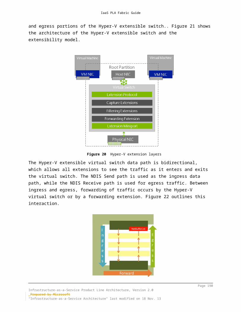
IaaS PLA Fabric Guide
Paper: http://sigops.org/sosp/sosp11/current/2011-Cascais/printable/11-calder.pdfSlides: http://sigops.org/sosp/sosp11/current/2011-Cascais/11-calder.pptxRecording: http://www.youtube.com/watch?v=QnYdbQO0yj4
Windows Azure storage services are critical in a hybrid cloud scenario because all data that is stored in Windows Azure, including IaaS virtual machine VHD files, utilizes the underlying Windows Azure storage services, which distribute data across multiple disks and data centers that are transparent to the running virtual machines.Each individual storage account has the following scalability targets:
Capacity – Up to 200 TBs Transactions – Up to 20,000 entities/messages/blobs per second Bandwidth for a Geo Redundant storage account
Ingress - up to 5 gigabits per second Egress - up to 10 gigabits per second
Bandwidth for a Locally Redundant storage account Ingress - up to 10 gigabits per second Egress - up to 15 gigabits per second
Note: The actual transaction and bandwidth targets that are achieved by your storage account will very much depend upon the size of objects, access patterns, and the type of workload that your application exhibits. To go above these targets, a service should be built to use multiple storage accounts and partition the blob containers, tables, queues, and objects across those storage accounts. By default, a single Windows Azure subscription gets 20 storage accounts. However, you can contact customer support to get more storage accounts if you have to store more data than that—for example, petabytes of data.Planning the usage of storage accounts for deployed virtual machines and services is a key design consideration.Virtual Hard Drives (VHDs)Drives, disks, and images are all virtual hard drives (VHDs) that are stored as page blobs within your storage account. There are actually several slightly different VHD formats: fixed, dynamic, and differencing. Currently, Windows Azure supports only the format that is named “fixed”. This format lays out the logical disk linearly within the file format, so that disk offset X is stored at blob offset X. At the end of the blob, a small footer describes the properties of the VHD. All of this, which is stored in the page blob, adheres to the standard VHD format, so that you can take this VHD and mount it on your server on-premises if you choose to. Often, the fixed format wastes space, because most disks have large unused ranges in them. However, we store our “fixed” VHDs as a page blob, which is a sparse format, so that we get the benefits of both the “fixed” and the “expandable” disks at the same time.
Page 190Infrastructure-as-a-Service Product Line Architecture, Version 2.0 Prepared by Microsoft“Infrastructure-as-a-Service Architecture" last modified on 4 Dec. 13

IaaS PLA Fabric Guide
Storage ReplicationWindows Azure storage services provide several options—some of which are enabled by default and included in the base pricing—for data redundancy and replication. For storage pricing information, refer to http://www.windowsazure.com/en-us/pricing/details/storage/.Locally Redundant Storage (LRS)Locally redundant storage provides highly durable and available storage within a single location (sub-region). Windows Azure maintains an equivalent of three copies (replicas) of your data within the primary location, as described in the previously linked Symposium on Operating Systems Principles (SOSP) paper; this ensures that Windows Azure can recover from common failures (disk, node, rack) without affecting your storage account’s availability and durability. All storage writes are performed synchronously across three replicas in three separate fault domains before success is returned to the client. If there were to be a major data center disaster, in which part of a data center were lost, Microsoft would contact customers about potential data loss for LRS by using the customer’s subscription contact information.Geo Redundant Storage (GRS)Geo Redundant Storage provides Windows Azure’s highest level of durability by additionally storing your data in a second location (sub region) within the same region hundreds of miles away from the primary location. All Windows Azure Blob and Table data is geo-replicated; however, Queue data is not geo-replicated at this time. With Geo Redundant Storage, Windows Azure maintains three copies (replicas) of the data in both the primary location and the secondary location. This ensures that each data center can recover from common failures on its own and provides a geo-replicated copy of the data in case of a major disaster. As in LRS, data updates are committed to the primary location before success is returned to the client. After this has been completed with GRS, these updates will be geo-replicated asynchronously to the secondary location.
Page 191Infrastructure-as-a-Service Product Line Architecture, Version 2.0 Prepared by Microsoft“Infrastructure-as-a-Service Architecture" last modified on 4 Dec. 13

IaaS PLA Fabric Guide
Primary Region Secondary Region
North Central US South Central US
South Central US North Central US
East US West US
West US East US
North Europe West Europe
West Europe North Europe
South East Asia East Asia
East Asia South East Asia
GRS is enabled by default for all storage accounts that are in production today. You can choose to disable this default state by turning off geo-replication in the Windows Azure portal for your accounts. You can also configure your redundant storage option when you create a new account via the Windows Azure Portal. For further details on GRS, see the following blog post: http://blogs.msdn.com/b/windowsazurestorage/archive/2011/09/15/introducing-geo-replication-for-windows-azure-storage.aspx
IMPORTANT: Geo-redundant storage is not compatible or supported when OS disk striping is utilized. For example, if you are using 16 1-TB disks in a virtual machine and using operating system striping to create a single 16-TB volume in the virtual machine, the storage must be locally redundant only. http://msdn.microsoft.com/en-us/library/windowsazure/dn133151.aspx
11.5.1.2 Storage – StorSimpleStorSimple, a Microsoft company, is the leading vendor of cloud-integrated storage. StorSimple solutions combine the data-management functions of primary storage, backup, archive, and disaster recovery (DR) with Windows Azure integration, enabling customers to optimize storage costs, data protection, and service agility. With its unique cloud-snapshot capability, StorSimple automatically protects and rapidly restores production data by using Windows Azure storage.The StorSimple solution combines a number of storage technologies, including Internet SCSI (iSCSI) Storage Area Network (SAN), snapshot, backup, deduplication, and compression with storage services that are offered by cloud service providers. StorSimple solutions seamlessly integrate advanced SAN technologies such as SSDs, SAS, automated storage tiering, deduplication, compression, and encryption
Page 192Infrastructure-as-a-Service Product Line Architecture, Version 2.0 Prepared by Microsoft“Infrastructure-as-a-Service Architecture" last modified on 4 Dec. 13
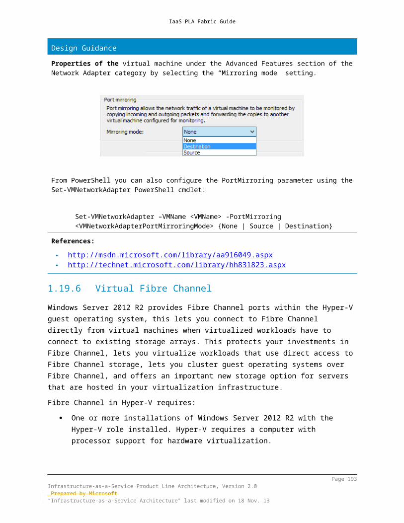
IaaS PLA Fabric Guide
with cloud storage to reduce the storage footprint significantly and lower both capital expenditure (CapEx) and operating expenditure (OpEx).With StorSimple, Microsoft has a strong solution for storage tiering (optimizing usage of different cost or performance storage options that are based automatically on data usage) that is also integrated tightly with Windows Azure storage. This significant new competitive advantage opens up a large number of architecture scenarios.NOTE: StorSimple is currently a hardware storage appliance available from Microsoft/StorSimple. The appliance acts as an iSCSI target for on-premises servers and provides several tiers of on-premises storage (SSD, SAS) while also natively integrating with Windows Azure storage.StorSimple consolidates primary storage, archive, backup, and DR through seamless integration with the cloud. By combining StorSimple software and a custom-designed enterprise-grade hardware platform, StorSimple solutions provide high performance for primary storage and enable revolutionary speed, simplicity, and reliability for backup and recovery.
ApplicationServers
Inactive Data + Backup Copies in Cloud
Speed of SSD/SAN + Elasticityof Cloud
SAS Local Tier
Most Active Data on SSD
StorSimple CiS
Azure Storage
Infrastructure consolidation. StorSimple solutions consolidate primary storage, archival, backup and disaster recovery through seamless integration with the cloud.
Simpler, faster backup & recovery. StorSimple cloud-based snapshots enable revolutionary speed, simplicity & reliability for backup and recovery.
Page 193Infrastructure-as-a-Service Product Line Architecture, Version 2.0 Prepared by Microsoft“Infrastructure-as-a-Service Architecture" last modified on 4 Dec. 13

IaaS PLA Fabric Guide
Users can achieve up to 100x faster data recovery vs. traditional backup methods used in the cloud.
Secure data storage. StorSimple applies AES-256 encryption for all data transferred and stored in the cloud using a private key that is known only to customers.
Lower overall storage costs. By integrating the cloud with local enterprise storage, StorSimple can reduce total storage costs by 60 to 80 percent.
StorSimple solutions use cloud storage as an automated storage tier, offloading capacity-management burdens and ongoing capital costs. Using local and cloud snapshots, application-consistent backups complete in a fraction of the time that traditional backup systems require, while reducing the amount of data that is transferred and stored in the cloud.Cloud-based and location-independent DR allows customers to recover their data from virtually any location that has an Internet connection and test their DR plans without affecting production systems and applications. Thin restore from data in the cloud enables users to resume operations after a disaster much faster than possible with physical or cloud-based tape.
Appliance Model* 5020 7020 5520 7520CapacityUsable local hard-drive capacity 2 TB 4 TB 10 TB 20 TB
SSD (Enterprise MLC [eMLC]) physical capacity 400 GB 600 GB 1.2 TB 2 TB
Effective local capacity** 4–10 TB 8–20 TB 20–50 TB 40–100 TB
Maximum capacity 100 TB 200 TB 300 TB 500 TB
High-Availability FeaturesDual, redundant, hot-swappable power-cooling modules (PCMs)
2 × 764 W PCMs, 100–240 VAC 2 × 764 W and 2 × 580 W PCMs, 100–240 VAC
Network interfaces 4 × 1 gigabit per second (Gbps) copper
Controllers Dual, redundant, hot-swappable, active or hot-standby controllers with automatic failover
RAID protection Yes, including SAS hot-spare
Storage FeaturesiSCSI with multipath IO support Yes
Primary data reduction Yes
Acceleration Nonvolatile random-access memory (NVRAM), SSD, cloud-storage acceleration
Microsoft certification Microsoft Windows Hardware Quality Labs (WHQL)
VMware certification Yes, VMware vSphere versions 4.1 and 5.1
Support for VMware vStorage APIs for Array Integration (VAAI)
Yes (pending future certification)
Automatic storage tiering SSD, SAS, and cloud storage
Adaptive I/O processing Yes, optimizes IO performance of mixed-pattern workloads
Data portability Yes, access data sets across StorSimple appliances
Data-Protection FeaturesLocal backups Yes, by using snapshots
Page 194Infrastructure-as-a-Service Product Line Architecture, Version 2.0 Prepared by Microsoft“Infrastructure-as-a-Service Architecture" last modified on 4 Dec. 13

IaaS PLA Fabric Guide
Offsite backups or tape elimination Yes, by using cloud snapshots and cloud clones
Microsoft VSS application-consistent backups Yes, by using Data Protection Console and hardware VSS provider
Windows Cluster Shared Volumes (CSV) and dynamic disk support
Yes; backup CSV, mirrored dynamic disks, multi-partition disks
Protected storage migration By using Windows host-side mirroring; allows online backups and nondisruptive cutover
Security FeaturesVirtual private storage Yes
Data-in-motion encryption HTTPS/Secure Socket Layer (SSL)
Data-at-rest encryption AES-256-CBC
Volume access control IQN, CHAP
Additional security features Multiple user accounts (local and Active Directory), role-based access, secure web proxy support
Manageability and ServiceabilityNondisruptive software upgrade Yes, updates and new releases
Hot-swappable components Controllers, power and cooling modules, NVRAM batteries, SSD and SAS drives
Management and monitoring Integrated web GUI, email alerts with call-home, Simple Network Management Protocol (SNMP) v1/v2c
Hardware FootprintForm factor 2U rack-mountable appliance 4U rack-
mountable appliance
Dimensions (L × W × H [in inches]) 24.8” × 19” × 3.46” 24.8” × 19” × 6.96”
The StorSimple solution uses the industry-standard iSCSI SAN protocol to connect to servers. ISCSI is easily configured for use with both Microsoft and VMware servers and is widely understood by storage administrators.StorSimple is intended to run as primary storage for enterprise tier 2 applications, including email, file shares, Microsoft SharePoint, content management systems, virtual machines and large unstructured data repositories. It is not built for latency-sensitive applications such as online transaction processing.The StorSimple solution uses three different types of storage: performance-oriented flash SSDs, capacity-oriented SAS disk drives and cloud storage. Data is moved from one type of storage to another according to its relative activity level and customer-chosen policies. Data that becomes more active is moved to a faster type of storage and data that becomes less active is moved to a higher capacity type of storage.There are four logical tiers in the system, two at the SSD level and one each in the SAS and cloud storage levels:Tier Name Storage Type Data Activity Reduction
AppliedNative SSD New, most active NoneHot SSD Existing, most
activeDeduplication
Warm SAS Between hot and Full
Page 195Infrastructure-as-a-Service Product Line Architecture, Version 2.0 Prepared by Microsoft“Infrastructure-as-a-Service Architecture" last modified on 4 Dec. 13

IaaS PLA Fabric Guide
coolCool Cloud Least active Full
The fourth column in the preceding table indicates the type of data-reduction technology that is used in the various tiers. The native tier has none, the hot tier uses deduplication (or “dedupe”), and the warm and cool tiers use full reduction, which means that data is both compressed and deduped. Notice that the progression from native tier to warm tier implies that data is first deduped before it is compressed.Dedupe reduces the amount of data stored in the system by identifying data duplicates and removing excess copies. Dedupe is particularly effective in virtual server environments. Compression reduces the amount of data stored in the system by identifying strings of repeated data values and replacing them with encoded shorthandAnother capacity-conserving technology in the StorSimple solution is thin provisioning, which allocates storage capacity as it is needed, as opposed to reserving capacity in advance. All storage in StorSimlpe is thinly provisioned.StorSimple provides a broad set of data-management tools that enable customers to use Windows Azure cloud storage in ways that are familiar to them, including archive and backup storage.Cloud snapshots are point-in-time copies of data that are stored in cool tiers in the cloud. All cloud snapshots are fully reduced (deduped and compressed) to minimize the amount of storage that is consumed.Cloud data reduction and cloud storage wide-area network (WAN) optimization refers to the fact that data that is transferred and stored in the cloud by a StorSimple solution already has been fully reduced. This minimizes the cost of cloud storage and the transaction costs and WAN bandwidth that are associated with storing data in the cloud.“Cloud tier” refers to the automated use of cloud storage as the “cool” tier in a StorSimple system. Data that is ranked lowest is sent to a cool tier in the cloud, where it remains until it is accessed again and promoted to the warm tier.StorSimple systems provide volume-level cloud mapping between storage volumes on StorSimple systems and the Windows Azure public cloud. Different volumes can have cool tiers on the same or different Windows Azure storage. Every StorSimple system keeps a metadata map that describes the state of the system and provides an image of the volume’s contents at the time that a snapshot is taken. This map is typically .1% the size of the stored data.AES-256 encryption is applied to all data that is transmitted and stored in the cloud by the StorSimple solution to ensure its security.
Page 196Infrastructure-as-a-Service Product Line Architecture, Version 2.0 Prepared by Microsoft“Infrastructure-as-a-Service Architecture" last modified on 4 Dec. 13

IaaS PLA Fabric Guide
SHA-256 hashing is applied to all data that is transmitted and stored in the cloud as a means to guarantee data integrity.Cloud clones are the equivalent of a synthetic full backup that have all of the current data for a volume at the time of the last snapshot. They are stored in the cool tier for use in disaster-recovery scenarios, but they occupy separate repositories from cloud snapshots and can reside within the same or a different cloud service as the volume’s cloud snapshots. The following figure shows that cloud clones are located in different repositories from cloud snapshots and that they can use the same or a different cloud service.
A thin restore is a disaster-recovery process whereby a StorSimple system downloads data from the cloud. The first thing that is downloaded is the metadata map, after which users and applications can start accessing their working sets and download them. As data is downloaded, it is ranked and placed in the appropriate tier.
Page 197Infrastructure-as-a-Service Product Line Architecture, Version 2.0 Prepared by Microsoft“Infrastructure-as-a-Service Architecture" last modified on 4 Dec. 13

IaaS PLA Fabric Guide
Thin restores tend to have extremely short Recovery Time Objectives (RTOs), because systems can begin accessing data after the metadata map has been downloaded. Thin restores do not restore cool data that does not belong to any working sets.Location-independent recovery refers to the ability to perform thin restores from any location that has a suitable Internet connection. This differs from legacy DR operations, which are restricted to having to run at specific recovery sites. Location independence adds an additional level of redundancy to the recovery process and does not require the capital investment that traditional replication solutions do. A customer that has multiple data-center locations can use StorSimple systems running in any of those locations to recover from disasters in any of the other sites. Similarly, a single StorSimple system can act as a spare for any of the others, providing an extremely cost-effective DR implementation.
PLA Rule Set – All Patterns
Mandatory: Consider cloud-integrated storage in the overall storage architecture for hybrid cloud.
Design Guidance
Overview of Hybrid Cloud Storage: https://microsoft.sharepoint.com/teams/Hybrid_Cloud_Storage/SitePages/
Page 198Infrastructure-as-a-Service Product Line Architecture, Version 2.0 Prepared by Microsoft“Infrastructure-as-a-Service Architecture" last modified on 4 Dec. 13

IaaS PLA Fabric Guide
Home.aspxSales and Planning Materials: https://microsoft.sharepoint.com/teams/Hybrid_Cloud_Storage/SitePages/Customer-Seller-Materials.aspx
Be aware of the StorSimple Azure Storage Acceleration Program (ASAP), which is a sales program whereby a customer that attaches $50,000 worth of Windows Azure to its enterprise agreement (EA) gets a free StorSimple appliance. For larger commitments, the customer can get the larger appliances. This program might or might not be available at the time of your engagement, but it should be explored. http://sharepoint/sites/windowsazureplatform/SitePages/WindowsAzureOffers.aspx
Internal Resources: http://infopedia/pages/cis.aspx
TechReady 16: https://tr16.techreadytv.com/sessions/AZR207
StorSimple data is encrypted on-premises prior to being stored in Windows Azure. The customer controls the encryption process and keys. Microsoft does not have access to the keys or the ability to decrypt the data. This is a major differentiating feature of this storage architecture.
11.5.2 Compute – Windows Azure IaaSThere are a number of compute-related services in Windows Azure, including web and worker roles, cloud services, and HD Insight. The focus of this paper is hybrid cloud IaaS. Although some of the other compute capabilities will be covered briefly, the focus will be on Windows Azure IaaS virtual machines.
11.5.2.1 Windows Azure Cloud ServiceWhen you create a virtual machine or application and run it in Windows Azure, the virtual machine or the code and configuration together are called a Windows Azure cloud service.By creating a cloud service, you can deploy multiple virtual machines or a multi-tier application in Windows Azure, defining multiple roles to distribute processing and allow flexible scaling of your application. A cloud service can consist of one or more virtual machines or web roles and worker roles, each of which has its own application files and configuration.Windows Azure virtual machines must be contained within cloud services. A single Windows Azure subscription by default is limited to 20 cloud services, and each cloud service can include up to 50 virtual machines.
Page 199Infrastructure-as-a-Service Product Line Architecture, Version 2.0 Prepared by Microsoft“Infrastructure-as-a-Service Architecture" last modified on 4 Dec. 13

IaaS PLA Fabric Guide
11.5.2.2 Windows Azure Virtual MachineAn IaaS virtual machine in Windows Azure is a persistent virtual machine in the cloud that you can control and manage. After you create a virtual machine in Windows Azure, you can delete and re-create it whenever you have to, and you can access the virtual machine just like any other server. Virtual hard disks (.vhd files) are used to create a virtual machine. You can use the following types of virtual hard disks to create a virtual machine:
Image—a template that you use to create a new virtual machine. An image does not have specific settings—such as the computer name and user account settings—that a running virtual machine has. If you use an image to create a virtual machine, an operating system disk is created automatically for the new virtual machine.
Disk—a VHD that you can start and mount as a running version of an operating system. After an image has been provisioned, it becomes a disk. A disk is always created when you use an image to create a virtual machine. Any VHD that is attached to virtualized hardware and running as part of a service is a disk.
You can use the following options to create a virtual machine from an image: Create a virtual machine by using a platform image from the Windows Azure
Management Portal. Create and upload a .vhd file that contains an image to Windows Azure, and
then use the uploaded image to create a virtual machine.Windows Azure provides specific combinations of central processing unit (CPU) cores and memory for IaaS virtual machines. These combinations are known as virtual machine sizes. When you create a virtual machine, you select a specific size. This size can be changed after deployment. The sizes that are available for virtual machines are the following:
Virtual Machine Size
CPU Cores
Memory
Disk Space for Cloud Services
Disk Space for Virtual Machines
Maximum Data Disks (1 TB Each)
Maximum IOPS (500 Maximum per Disk)
ExtraSmall
Shared
768 MB 19 GB 20 GB 1 1 × 500
Small 1 1.75 GB
224 GB 70 GB 2 2 × 500
Medium 2 3.5 GB 489 GB 135 GB 4 4 × 500
Page 200Infrastructure-as-a-Service Product Line Architecture, Version 2.0 Prepared by Microsoft“Infrastructure-as-a-Service Architecture" last modified on 4 Dec. 13

IaaS PLA Fabric Guide
Large 4 7 GB 999 GB 285 GB 8 8 × 500
ExtraLarge
8 14 GB 2,039 GB
605 GB 16 16 × 500
A5 2 14 GB 4 4 x 500
A6 4 28 GB 999 GB 285 GB 8 8 × 500
A7 8 56 GB 2,039 GB
605 GB 16 16 × 500
Source: Virtual Machine Sizes http://msdn.microsoft.com/en-us/library/windowsazure/dn197896.aspx
IMPORTANT: Note that virtual machines will begin to incur cost as soon as they are provisioned, regardless of whether or not they are turned on.
Page 201Infrastructure-as-a-Service Product Line Architecture, Version 2.0 Prepared by Microsoft“Infrastructure-as-a-Service Architecture" last modified on 4 Dec. 13
IaaS PLA Fabric Guide
PLA Rule Set – All Patterns
Mandatory: When you are creating Windows Azure virtual machines, be sure to use very complex passwords and non-default ports for common traffic such as Remote Desktop Protocol (RDP). Generic ports and passwords will be guessed, and virtual machines will be compromised.
Recommended: Use non-default ports for RDP access to Windows Azure virtual machines, or consider using Windows Azure virtual networks and VPN, so that only virtual machines that require inbound access from the Internet are configured with publically accessible endpoints.
Design Guidance
Small is the smallest size that is recommended for production workloads.
Select a virtual machine that has 4 or 8 CPU cores when you are using SQL Server Enterprise Edition.
The ExtraSmall virtual machine size is available only by using Windows Azure SDK version 1.3 or higher.
Cloud services require more disk space than a virtual machine because of system requirements. For the web and worker roles, the system files reserve 4 GB of space for the Windows page file and 2 GB of space for the Windows dump file.
11.5.2.3 Windows Azure Virtual Machine StorageA Windows Azure virtual machine is created from an image or a disk. All virtual machines use one operating system disk, a temporary local disk, and possibly multiple data disks. All images and disks, except for the temporary local disk, are created from VHDs, which are .vhd files that are stored as page blobs in a storage account in Windows Azure. You can use platform images that are available in Windows Azure to create virtual machines, or you can upload your own images to create customized virtual machines. The disks that are created from images are also stored in Windows Azure storage. You can create new virtual machines easily by using existing disks.VHD FilesA .vhd file is stored as a page blob in Windows Azure storage and can be used for creating images, operating system disks, or data disks in Windows Azure. You can upload a .vhd file to Windows Azure and manage it just as you would any other
Page 202Infrastructure-as-a-Service Product Line Architecture, Version 2.0 Prepared by Microsoft“Infrastructure-as-a-Service Architecture" last modified on 4 Dec. 13

IaaS PLA Fabric Guide
page blob. The .vhd files can be copied or moved, and they can be deleted as long as a lease does not exist on the VHD.A VHD can be in either a fixed format or a dynamic format; currently, however, only the fixed format of .vhd files is supported in Windows Azure. The fixed format lays out the logical disk linearly within the file, so that disk offset X is stored at blob offset X. At the end of the blob, a small footer describes the properties of the VHD. Often, the fixed format wastes space because most disks contain large unused ranges. However, in Windows Azure, fixed .vhd files are stored in a sparse format, so that you receive the benefits of both the fixed and dynamic disks at the same time.When you create a virtual machine from an image, a disk is created for the virtual machine, which is a copy of the original .vhd file. To protect against accidental deletion, a lease is created if you create an image, an operating system disk, or a data disk from a .vhd file.Before you can delete the original .vhd file, you must first delete the disk or image to remove the lease. To delete a .vhd file that is being used by a virtual machine as an operating system disk, you must delete the virtual machine, delete the operating system disk, and then delete the original .vhd file. To delete a .vhd file that is used as a source for a data disk, you must detach the disk from the virtual machine, delete the disk, and then delete the .vhd file.
Design Guidance
Note that Windows Azure virtual machines do not support the VHDX format. Ensure that any virtual machines or images that are planned for use in or migration to Windows Azure use the VHD format.
Note that if a VHD file on-premises is a dynamic VHD, it is converted to “fixed” when it is uploaded to Windows Azure.
VHD files can be created on-premises by using Hyper-V or Disk Manager and uploaded to Windows Azure. Uploaded VHDs can then be added as disks.
ImagesAn image is a .vhd file that you can use as a template to create a new virtual machine. An image is a template because it does not have specific settings—such as the computer name and user account settings—that a configured virtual machine does. You can use images from the Image Gallery to create virtual machines, or you can create your own images.The Windows Azure Management Portal enables you to choose from several platform images to create a virtual machine. These images contain the Windows Server 2008 R2 operating system, Windows Server 2012 operating system, and
Page 203Infrastructure-as-a-Service Product Line Architecture, Version 2.0 Prepared by Microsoft“Infrastructure-as-a-Service Architecture" last modified on 4 Dec. 13

IaaS PLA Fabric Guide
several distributions of the Linux operating system. A platform image can also contain applications, such as SQL Server.To create a Windows Server image, you must run the Sysprep command on your development server to generalize and shut it down before you can upload the .vhd file that contains the operating system.
Design Guidance
Custom operating system images for Windows or Linux can be created on-premises and uploaded to Windows Azure. Customer base images can be utilized if they have been “sysprepped” and are using operating systems that are supported in Windows Azure.
Virtual machine images can be made to domain-join Windows Azure–hosted or VPN-connected Active Directory domains.
Consider the storage locations of images in Windows Azure in terms of where virtual machines will be provisioned, so that images do not have to be copied across data centers.
DisksYou use disks in different ways with a virtual machine in Windows Azure. An operating system disk is a VHD that you use to provide an operating system for a virtual machine. A data disk is a VHD that you attach to a virtual machine to store application data. You can create and delete disks whenever you have to.You choose from among multiple ways to create disks, depending on the needs of your application. For example, a typical way to create an operating system disk is to use an image from the Image Gallery when you create a virtual machine, and an operating system disk is created for you. You can create a data disk by attaching an empty disk to a virtual machine, and a new data disk is created for you. You can also create a disk by using a VHD file that has been uploaded or copied to a storage account in your subscription. You cannot use the portal to upload VHD files, but you can use other tools that work with Windows Azure storage—including the Windows Azure PowerShell cmdlets—to upload or copy the file.
Operating System DiskEvery virtual machine has one operating system disk. You can upload a VHD that can be used as an operating system disk, or you can create a virtual machine from an image, and a disk is created for you. An operating system disk is a VHD that you can start and mount as a running version of an operating system. Any VHD that is attached to virtualized hardware and running as part of a service is an operating system disk. The maximum size of an operating system disk can be 127 GB. When an operating system disk is created in Windows Azure, three copies of the disk are
Page 204Infrastructure-as-a-Service Product Line Architecture, Version 2.0 Prepared by Microsoft“Infrastructure-as-a-Service Architecture" last modified on 4 Dec. 13

IaaS PLA Fabric Guide
created for high durability. Additionally, if you choose to use DR that is geo-replication–based, your VHD is also replicated at a distance of more than 400 miles away. Operating system disks are registered as Serial Advanced Technology Attachment (SATA) drives and labeled as drive C.Data DiskA data disk is a VHD that can be attached to a running virtual machine to store application data persistently. You can upload and attach to the virtual machine a data disk that already contains data, or you can use the Windows Azure Management Portal to attach an empty disk to the virtual machine. The maximum size of a data disk is 1 TB; you are limited in the number of disks that you can attach to a virtual machine, based on the size of the virtual machine. Data disks are registered as SCSI drives, and you can make them available for use within the operating system by using the Disk Manager in Windows. The maximum number of data disks per virtual machine size was shown in the preceding table.If multiple data disks are attached to a virtual machine, striping inside the virtual machine operating system can be utilized to create a single volume on the multiple attached disks (a volume of up to 16 TB that consists of a stripe of 16 1-TB data disks). As mentioned previously, use of operating system striping is not possible with geo-redundant data disks.
Temporary Local DiskEach virtual machine that you create has a temporary local disk, which is labeled as drive D. This disk exists only on the physical host server on which the virtual machine is running; it is not stored in blobs on Windows Azure storage. This disk is used by applications and processes that are running in the virtual machine for transient and temporary storage of data. It is used also to store page files for the operating system. Note that any data will not survive a host-machine failure or any other operation that requires moving the virtual machine to another piece of hardware.Use of the letter D for the drive is by default. You can change the letter by using the following workaround:
1. Deploy the virtual machine normally, with or without the second data disk attached. (The data disk initially will be drive E, if it is a formatted volume.)
2. Move the pagefile from drive D to drive C.3. Reboot the virtual machine.4. Swap the drive letters on the current drives D and E.5. Optionally, move the pagefile back to the resource drive (now drive E).
Page 205Infrastructure-as-a-Service Product Line Architecture, Version 2.0 Prepared by Microsoft“Infrastructure-as-a-Service Architecture" last modified on 4 Dec. 13

IaaS PLA Fabric Guide
If the virtual machine is resized or moved to new hardware for service healing, the drive naming will stay in place. The data disk will stay at drive D, and the resource disk will always be the first available drive letter (which would be E, in this example).
Host CachingThe operating system disk and data disk has a host-caching setting (sometimes called host-cache mode) that enables improved performance under some circumstances. However, these settings can have a negative effect on performance in other circumstances, depending on the application. By default, host caching is OFF for both read operations and write operations for data disks. Host caching is ON by default for read and write operations for operating system disks.RDP and Remote Windows PowerShellNew virtual machines that are created through the Windows Azure Management portal will have both RDP and Remote Windows PowerShell available.
11.5.2.4 Windows Azure Virtual Machine Placement and Affinity GroupsUsing affinity groups is how you group the services in your Windows Azure subscription that must work together to achieve optimal performance. When you create an affinity group, it lets Windows Azure know to keep all of the services that belong to your affinity group running at the same data-center cluster. For example, if you wanted to keep different virtual machines close together (within the same data center), you would specify the same affinity group for those virtual machines and associated storage. That way, when you deploy those virtual machines, Windows Azure will locate them in a data center as close to each other as possible. This reduces latency and increases performance, while potentially lowering costs.Affinity groups are defined at the subscription level, and the name of each affinity group has to be unique within the subscription. When you create a new resource, you can either use an affinity group that you previously created or create a new one.PLA Rule Set – All Patterns
Recommended: For related virtual machines (such as two tiers within an application), utilize affinity groups to ensure that they are placed in the same data center or cluster in Windows Azure.
Page 206Infrastructure-as-a-Service Product Line Architecture, Version 2.0 Prepared by Microsoft“Infrastructure-as-a-Service Architecture" last modified on 4 Dec. 13

IaaS PLA Fabric Guide
11.5.2.5 Windows Azure Endpoints and ACLsWhen you create a virtual machine, it is fully accessible from any of your other virtual machines that are within the Windows Azure virtual network to which it is connected. All protocols—such as TCP, UDP, and Internet Control Message Protocol (ICMP)—are supported within the local virtual network. Virtual machines on your virtual network are automatically given an internal IP address from a private range (RFC 1918) that you defined when you created the network.To provide access to your virtual machines from outside of your virtual network, you will have to use the external IP address and configure public endpoints. These endpoints are similar to firewall and port forwarding rules and can be configured in the Windows Azure portal. By default, when they are created by using the Windows Azure Management Portal, ports for both RDP and Remote Windows PowerShell are opened. These ports use random public-port addresses, which are mapped to the correct ports on the virtual machines. You can remove these preconfigured endpoints if you have network connectivity via a VPN.
PLA Rule Set – All Patterns
Recommended: Utilize least-privilege and least-required access strategies for virtual machines. Verify that the default endpoints such as RDP are required, and enable new endpoints only for required application or workload functionality.
A Network Access Control List (ACL) is a security enhancement available for your Windows Azure deployment. An ACL provides the ability to selectively permit or deny traffic for a virtual machine endpoint. This packet filtering capability provides an additional layer of security. Currently, you can specify network ACLs for virtual machines endpoints only. You cannot specify an ACL for a virtual network or a specific subnet contained in a virtual networkUsing Network ACLs, you can do the following:
Selectively permit or deny incoming traffic based on remote subnet IPv4 address range to a virtual machine input endpoint.
Blacklist IP addresses Create multiple rules per virtual machine endpoint Specify up to 50 ACL rules per virtual machine endpoint Use rule ordering to ensure the correct set of rules are applied on a given
virtual machine endpoint (lowest to highest) Specify an ACL for a specific remote subnet IPv4 address.
An ACL is an object that contains a list of rules. When you create an ACL and apply it to a virtual machine endpoint, packet filtering takes place on the host node of your VM. This means the traffic from remote IP addresses is filtered by the host
Page 207Infrastructure-as-a-Service Product Line Architecture, Version 2.0 Prepared by Microsoft“Infrastructure-as-a-Service Architecture" last modified on 4 Dec. 13

IaaS PLA Fabric Guide
node for matching ACL rules instead of on your VM. This prevents your VM from spending the precious CPU cycles on packet filtering.When a virtual machine is created, a default ACL is put in place to block all incoming traffic. However, if an endpoint is created for (port 3389), then the default ACL is modified to allow all inbound traffic for that endpoint. Inbound traffic from any remote subnet is then allowed to that endpoint and no firewall provisioning is required. All other ports are blocked for inbound traffic unless endpoints are created for those ports. Outbound traffic is allowed by default.You can selectively permit or deny network traffic for a virtual machine input endpoint by creating rules that specify “permit” or “deny”. It’s important to note that by default, when an endpoint is created, all traffic is denied to the endpoint. For that reason, it’s important to understand how to create permit/deny rules and place them in the proper order of precedence if you want granular control over the network traffic that you choose to allow to reach the virtual machine endpoint.Points to consider:
1. No ACL – By default when an endpoint is created, we permit all for the endpoint.
2. Permit - When you add one or more “permit” ranges, you are denying all other ranges by default. Only packets from the permitted IP range will be able to communicate with the virtual machine endpoint.
3. Deny - When you add one or more “deny” ranges, you are permitting all other ranges of traffic by default.
4. Combination of Permit and Deny - You can use a combination of “permit” and “deny” when you want to carve out a specific IP range to be permitted or denied.
Network ACLs can be set up on specific virtual machine endpoints. For example, you can specify a network ACL for an RDP endpoint created on a virtual machine which locks down access for certain IP addresses. The table below shows a way to grant access to public virtual IPs (VIPs) of a certain range to permit access for RDP. All other remote IPs are denied. We follow a lowest takes precedence rule order.Network ACLs can be specified on a Load balanced set (LB Set) endpoint. If an ACL is specified for a LB Set, the Network ACL is applied to all Virtual Machines in that LB Set. For example, if a LB Set is created with “Port 80” and the LB Set contains 3 VMs, the Network ACL created on endpoint “Port 80” of one VM will automatically apply to the other VMs.
Page 208Infrastructure-as-a-Service Product Line Architecture, Version 2.0 Prepared by Microsoft“Infrastructure-as-a-Service Architecture" last modified on 4 Dec. 13

IaaS PLA Fabric Guide
11.5.2.6 Windows Azure Virtual Machine High Availability (HA)You can ensure the availability of your application by using multiple Windows Azure virtual machines. By using multiple virtual machines in your application, you can make sure that your application is available during local network failures, local disk-hardware failures, and any planned downtime that the platform might require.You manage the availability of your application that uses multiple virtual machines by adding the virtual machines to an availability set. Availability sets are directly related to fault domains and update domains. A fault domain in Windows Azure is defined by avoiding single points of failure, like the network switch or power unit of a rack of servers. In fact, a fault domain is closely equivalent to a rack of physical servers. When multiple virtual machines are connected together in a cloud service, an availability set can be used to ensure that the virtual machines are located in different fault domains. The following diagram shows two availability sets, each of which contains two virtual machines.
Page 209Infrastructure-as-a-Service Product Line Architecture, Version 2.0 Prepared by Microsoft“Infrastructure-as-a-Service Architecture" last modified on 4 Dec. 13

IaaS PLA Fabric Guide
Windows Azure periodically updates the operating system that hosts the instances of an application. A virtual machine is shut down when an update is applied. An update domain is used to ensure that not all of the virtual machine instances are updated at the same time. When you assign multiple virtual machines to an availability set, Windows Azure ensures that the virtual machines are assigned to different update domains. The previous diagram shows two virtual machines running Internet Information Services (IIS) in separate update domains and two virtual machines running SQL Server also in separate update domains.
IMPORTANT: The Windows Azure virtual machine high availability (HA) concepts are not the same as on-premises Hyper-V. Windows Azure does not support live migration or movement of running virtual machines. For HA, multiple virtual machines per application or role must be created, and Windows Azure constructs such as availability groups and load balancing must be utilized. Each application that is being considered for deployment must be analyzed to determine how HA features of Windows Azure can be utilized. If a given application cannot use multiple roles or instances for HA (meaning that a single virtual machine that is running the application must be online at all times), Windows Azure cannot support that requirement.
You should use a combination of availability sets and load-balancing endpoints (discussed in subsequent sections) to help ensure that your application is always available and running efficiently.
Page 210Infrastructure-as-a-Service Product Line Architecture, Version 2.0 Prepared by Microsoft“Infrastructure-as-a-Service Architecture" last modified on 4 Dec. 13

IaaS PLA Fabric Guide
PLA Rule Set – All Patterns
Mandatory: To qualify for the Windows Azure virtual machine availability SLA, two or more virtual machines in the same availability group are required. The Windows Azure SLA does not apply to single virtual machines.
Recommended: Production workloads should be provisioned with two or more virtual machines in an availability group.
For more information on Windows Azure host updates and how they affect virtual machines and services, refer to the following:
Windows Azure Host Updateshttp://blogs.technet.com/b/markrussinovich/archive/2012/08/22/3515679.aspx
Design Guidance
For each workload that is deployed in Windows Azure virtual machines and each tier of that workload, strongly consider deploying an availability set for each tier and two or more virtual machines for the tier that is within that availability set. This provides virtual machine HA through host updates and other scheduled fabric-level maintenance.
For data-center and geographic resiliency, ensure that geo-replication is enabled for storage.
Consider the use of affinity groups to ensure that related virtual machines and resources are located within the same data center, while using geo-replication for availability across data centers.
Remember that host maintenance activities can take down any individual virtual machine, so that workloads that are hosted in Windows Azure likely will require workload-level HA, such as load balancing.
11.5.2.7 Windows Azure Virtual Machine Load BalancingExternal communication with virtual machines can occur through Windows Azure endpoints. These endpoints are used for different purposes, such as load-balanced traffic or direct virtual machine connectivity like RDP or SSH. You define endpoints
Page 211Infrastructure-as-a-Service Product Line Architecture, Version 2.0 Prepared by Microsoft“Infrastructure-as-a-Service Architecture" last modified on 4 Dec. 13
IaaS PLA Fabric Guide
that are associated with specific ports and are assigned a specific communication protocol. An endpoint can be assigned a protocol of TCP or UDP (the TCP protocol includes HTTP and HTTPS traffic). Each endpoint that is defined for a virtual machine is assigned a public and private port for communication. The private port is defined for setting up communication rules on the virtual machine, and the public port is used by Windows Azure to communicate with the virtual machine from external resources.If you configure it, Windows Azure provides round-robin load balancing of network traffic to publicly defined ports of a cloud service. When your cloud service contains instances of web roles or worker roles, you enable this load balancing by setting the number of instances that are running in the service to greater than or equal to two and by defining a public endpoint in the service definition. For virtual machines, you can set up load balancing by creating new virtual machines, connecting them under a cloud service, and adding load-balanced endpoints to the virtual machines.A load-balanced endpoint is a specific TCP or UDP endpoint that is used by all virtual machines that are contained in a cloud service. The following image shows a load-balanced endpoint that is shared among three virtual machines and uses a public and private port of 80:
A virtual machine must be in a healthy state to receive network traffic. You can optionally define your own method for determining the health of the virtual machine by adding a load-balancing probe to the load-balanced endpoint. Windows Azure probes for a response from the virtual machine every 15 seconds and takes a virtual machine out of the rotation if no response has been received after two probes. You must use Windows PowerShell to define probes on the load balancer.
Page 212Infrastructure-as-a-Service Product Line Architecture, Version 2.0 Prepared by Microsoft“Infrastructure-as-a-Service Architecture" last modified on 4 Dec. 13

IaaS PLA Fabric Guide
Design Guidance
Load balancing is required for any workload or service that must remain online through host or virtual machine maintenance.
LoadBalancerProbe Schema http://msdn.microsoft.com/en-us/library/windowsazure/jj151530.aspx
11.5.2.8 Limitations of Windows Azure IaaS Virtual MachinesWhile Windows Azure IaaS virtual machines are full running instances of Windows or Linux from an operating system perspective, in some cases—because they are virtual machines or are running on a cloud infrastructure—some operating system features and capabilities might not be supported. The following table provides examples of Windows operating system features that are not supported in Windows Azure virtual machines:
OS Roles/Features Not Supported in Azure IaaS VMs
Explanation
Hyper-V It is not supported to run Hyper-V within a virtual machine that is already running on Hyper-V.
Dynamic Host Configuration Protocol (DHCP)
Windows Azure virtual machines do not support broadcast traffic to other virtual machines.
Failover clustering Windows Azure does not handle clustering’s “virtual” or floating IP addressing for network resources.
BitLocker on operating system disk
Windows Azure does not support Trusted Platform Module (TPM).
Client operating systems Windows Azure licensing does not support client operating systems.
Virtual Desktop Infrastructure (VDI) using RDS
Windows Azure licensing does not support the running of VDI virtual machines through RDS.
Additionally, over time, more Microsoft applications are being tested and supported for deployment in Windows Azure virtual machines. The following Microsoft
Page 213Infrastructure-as-a-Service Product Line Architecture, Version 2.0 Prepared by Microsoft“Infrastructure-as-a-Service Architecture" last modified on 4 Dec. 13
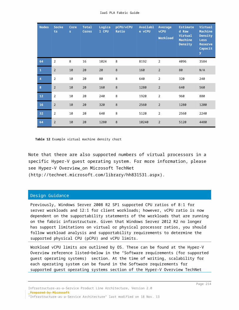
IaaS PLA Fabric Guide
Knowledge Base (KB) article contains the list of Microsoft software that is supported in Windows Azure virtual machines.
Microsoft Software Supported in Windows Azure Virtual Machineshttp://support.microsoft.com/kb/2721672
PLA Rule Set – All Patterns
Mandatory: Verify that any Microsoft or third-party software that you intend to deploy in Windows Azure is supported on Windows Azure.
11.5.3 Network - Windows Azure NetworkingThe Windows Azure network service provides a variety of solutions for network connectivity within Windows Azure, as well as between on-premises infrastructure and Windows Azure. In calendar year 2012, Windows Azure made substantial upgrades to the Windows Azure fabric and network architecture to flatten the design and significantly increase the horizontal (or node-to-node) bandwidth that is available.These upgrades have been described publically and, along with software improvements, provide significant bandwidth between compute and storage that uses a flat-network topology. The specific implementation of the flat network for Windows Azure is referred to as the “Quantum 10” (Q10) network architecture. Q10 provides a fully non-blocking 10 Gbps–based fully meshed network, providing an aggregate backplane in excess of 50 terabytes per second (Tbps) of bandwidth for each Windows Azure data center. Another major improvement in reliability and throughput is moving from a hardware load balancer to a software load balancer. After these upgrades, the storage architecture and design that were described in previous sections was tuned to leverage the new Q10 network fully to provide flat-network storage for Windows Azure Storage. For architectural details of the Q10 design, see VL2: A Scalable and Flexible Data Center Network (link)
11.5.3.1 Windows Azure Virtual NetworkWindows Azure Virtual Network enables you to create secure site-to-site connectivity and protected private virtual networks in the cloud. You can specify the address space that will be used for both your virtual network and the virtual network gateway. Additionally, new name-resolution features allow you to connect directly to role instances and virtual machines by host name. These features allow
Page 214Infrastructure-as-a-Service Product Line Architecture, Version 2.0 Prepared by Microsoft“Infrastructure-as-a-Service Architecture" last modified on 4 Dec. 13
IaaS PLA Fabric Guide
you to use Windows Azure as you would a branch office or as a protected private virtual network in the cloud.Before you configure Windows Azure Virtual Network, you should carefully consider possible scenarios. For this release, it can be difficult to make changes after your virtual network has been created and you have deployed role instances and virtual machines. After this stage of deployment, you cannot easily modify the baseline network configuration, and many values cannot be modified without pulling back roles and virtual machines and then reconfiguring. Therefore, you should not attempt to create a virtual network and then try to adapt the scenario to fit the network. Scenarios that are enabled by Windows Azure virtual networks include:
Create secure site-to-site network connectivity between Windows Azure and your on-premises network, effectively creating a virtual branch office or data center in the cloud. This is possible by using a hosted VPN gateway and a supported VPN gateway device (including Windows Server 2012 RRAS).
Extend your enterprise networks into Windows Azure. Migrate existing applications and services to Windows Azure. Hostname resolution. You can specify your own on-premises Domain Name
System (DNS) server or a dedicated DNS server that is running elsewhere. Persistent dynamic IP addresses for virtual machines. This means that the
internal IP address of your virtual machines will remain persistent and will not change, even when you restart a virtual machine.
Join virtual machines that are running in Windows Azure to your domain that is running on-premises.
Create point-to-site virtual networks, enabling individual workstations to establish VPN connectivity to Windows Azure virtual networks—for example for developers in a remote site to be able to connect to Windows Azure networks.
Windows Azure virtual networks have the following properties: Virtual machines can have only one IP address (or one IP plus a virtual IP, if
they are load-balanced). Every virtual machine gets an IP from DHCP; static IP addresses are not
supported. Virtual machines on the same virtual network can communicate. Virtual machines on different virtual networks cannot communicate directly. Egress traffic from Windows Azure is charged. Ingress traffic to Windows Azure is free (not charged). All virtual machines by default have Internet access. There is currently no
official way to force Internet traffic to go through on-premises devices, such as proxies.
There is only one virtual gateway per virtual network.As mentioned previously, virtual networks and subnets in Windows Azure must utilize private (RFC 1918) IP-address ranges.
Page 215Infrastructure-as-a-Service Product Line Architecture, Version 2.0 Prepared by Microsoft“Infrastructure-as-a-Service Architecture" last modified on 4 Dec. 13

IaaS PLA Fabric Guide
11.5.3.2 Windows Azure VPN (Site-to-Site)You can link your Windows Azure virtual network to an on-premises network via site-to-site VPN connection.
To create a secure VPN connection, the person who will configure the VPN device must coordinate with the person who will create the Management Portal configuration. This coordination is required, because the Management Portal requires IP-address information from the VPN device to start the VPN connection and create the shared key. The shared key is then exported to configure the VPN gateway device and complete the connection.Sample configuration scripts are available for many, but not all, VPN devices. If your VPN device is in the list of supported devices, you can download the corresponding sample configuration script to help you configure the device. If you do not see your VPN device in the list, your device still might work with Windows Azure virtual network if it satisfies the requirements. For more information, see Requirements for VPN devices.
PLA Rule Set – All Patterns
Mandatory: Use a Windows Azure–approved VPN device or Windows Server 2012 R2 RRAS.
11.5.3.3 Windows Azure VPN (Point-to-Site)The Windows Azure point-to-site VPN allows you to set up VPN connections between individual computers and a Windows Azure virtual network without the need for a VPN device. This feature is called Point-to-Site Virtual Private Networking. It greatly
Page 216Infrastructure-as-a-Service Product Line Architecture, Version 2.0 Prepared by Microsoft“Infrastructure-as-a-Service Architecture" last modified on 4 Dec. 13

IaaS PLA Fabric Guide
simplifies the setup of secure connections between Windows Azure and client computers, whether from an office environment or from remote locations.It is especially useful for developers who want to connect to a Windows Azure virtual network (and to the individual virtual machines within it) from either behind a corporate firewall or a remote location. Because the connection is point-to-site, they do not need their IT staff to perform any activities to enable it, and no VPN hardware must be installed or configured. Instead, you can just use the built-in Windows VPN client to tunnel to your virtual network in Windows Azure. This tunnel uses the Secure Sockets Tunneling Protocol (SSTP) and can traverse firewalls and proxies automatically, while giving you complete security.Here’s a visual representation of the point-to-site scenarios enabled:
11.5.3.4 Affinity Groups
After you have created a virtual network, an affinity group will also be created. When you create resources (such as storage accounts) in Windows Azure, an affinity group will let Window Azure know that you want to keep these resources located together. When you have an affinity group, you should reference this always when you are creating related resources.
Page 217Infrastructure-as-a-Service Product Line Architecture, Version 2.0 Prepared by Microsoft“Infrastructure-as-a-Service Architecture" last modified on 4 Dec. 13

IaaS PLA Fabric Guide
11.5.3.5 Name ResolutionTo refer to virtual machines and role instances within a cloud service by host name directly, Windows Azure provides a name-resolution service. This service is used for internal host-name resolution within a cloud service. The name-resolution service that is provided by Windows Azure is a completely separate service from that which is used to access your public endpoints on the Internet.Before you deploy role instances or virtual machines, you must consider how you want name resolution to be handled. Two options are available: you can either use internal name resolution that is provided by Windows Azure or choose to specify a DNS server that is not maintained by Windows Azure. Not all configuration options are available for every deployment type. Carefully consider your deployment scenario before you make this choice.
11.5.3.6 DNS ConsiderationsName resolution is an important consideration for virtual network design. Even though you may create a secure site-to-site VPN connection, communication by host name is not possible without name resolution. There are multiple ways to provide name resolution for your Windows Azure virtual network. You can use the name resolution that Windows Azure has provided, or you can use your own DNS server.When you define a virtual network, Windows Azure will provide a DNS service; however, if you want to use your existing DNS infrastructure, or you have a dependency on Active Directory you need to define your own. Defining your own in the virtual network configuration doesn’t actually create a DNS server; instead you are configuring the DHCP service to include the DNS server IP that you define. This DNS server could be a reference to an existing on-premises DNS server, or a new DNS server that you will provision in the cloud.Configuring your virtual network to use Windows Azure-provided name resolution is a relatively simple option. However, you may require a more full-featured DNS solution in order to support virtual machines or complex configurations. Your choice of name resolution method should be based on the scenario that it will support.
Scenario Name Resolution
Points to Consider
Cross-premises: Name resolution between role instances or virtual machines in Windows Azure and on-premises computers
DNS solution of your choice (Not Windows Azure-provided)
Name resolution (DNS) design
Address space
Supported VPN gateway
Page 218Infrastructure-as-a-Service Product Line Architecture, Version 2.0 Prepared by Microsoft“Infrastructure-as-a-Service Architecture" last modified on 4 Dec. 13

IaaS PLA Fabric Guide
device
Internet-accessible IP address for your VPN gateway device
Cross-premises: Name resolution between on-premises computers and role instances or virtual machines in Windows Azure
DNS solution of your choice (Not Windows Azure-provided)
Name resolution (DNS) design
Address space
Supported VPN gateway device
Internet-accessible IP address for your VPN gateway device
Name resolution between role instances located in the same cloud service
Windows Azure name resolution (internal)
Name resolution (DNS) design
Name resolution between virtual machines located in the same cloud service
Windows Azure name resolution (internal)
Name resolution (DNS) design
Name resolution between virtual machines and role instances located in the same Virtual Network, but different cloud services
DNS solution of your choice (Not Windows Azure-provided)
Name resolution (DNS) design
Address space
Supported VPN gateway device
Internet-accessible IP address for your VPN gateway device
Name resolution between virtual machines and role instances that are located in the same cloud services but not in a Windows Azure virtual network.
Not applicable Virtual machines and role instances cannot be deployed in the same cloud service.
Name resolution between role instances that are located in different cloud services but not in a Windows Azure virtual network.
Not applicable Connectivity between virtual machines or role instances in different cloud services is not supported outside a virtual network.
Page 219Infrastructure-as-a-Service Product Line Architecture, Version 2.0 Prepared by Microsoft“Infrastructure-as-a-Service Architecture" last modified on 4 Dec. 13

IaaS PLA Fabric Guide
Name resolution between virtual machines that are located in the same Windows Azure virtual network.
DNS solution of your choice (not Windows Azure–provided)
Name-resolution (DNS) design.
Address space.
Supported VPN gateway device.
Internet-accessible IP address for your VPN gateway device.
Use name resolution to direct traffic between data centers.
See Traffic Manager.
Control the distribution of user traffic to Windows–Azure hosted services.
See Traffic Manager.
Although Windows Azure–provided name resolution requires very little configuration, it is not the appropriate choice for all deployments. If your network requires name resolution across cloud services or across premises, you must use your own DNS server. If you want to register additional DNS records of your own, you will have to use a DNS solution that is not Windows Azure–provided.
Design Guidance
Windows Azure–provided DNS considerations
Host-name resolution is not available between virtual machines or role instances that are distributed across multiple cloud services.
Name resolution between virtual networks is not available.
Use of multiple host names for the same virtual machine or role instance is not supported.
Cross-premises name resolution is not available.
Reverse lookups (PTR) records are not available.
The Windows Azure–created DNS suffix cannot be modified.
You cannot register your own records in Windows Azure–provided DNS manually.
WINS and NetBIOS are not supported. (You cannot list your virtual machines in the network browser in Windows Explorer.)”
Page 220Infrastructure-as-a-Service Product Line Architecture, Version 2.0 Prepared by Microsoft“Infrastructure-as-a-Service Architecture" last modified on 4 Dec. 13

IaaS PLA Fabric Guide
Host names must be DNS-compatible. (They must use only numbers 0–9, letters a–z, and the dash (-), and they cannot start or end with a dash. See RFC 3696 section 2.)
DNS query traffic is throttled per virtual machine. If your application performs frequent DNS queries on multiple target names, it is possible for some queries to time out. A possible workaround is to reduce DNS query traffic from each virtual machine and retry the lookup.
11.5.3.7 Windows Azure Traffic ManagerThe Windows Azure Traffic Manager allows you to control the distribution of user traffic to Windows Azure–hosted services. The hosted services can be running in the same data center or in different centers around the world. Traffic Manager works by applying an intelligent policy engine to the DNS queries on your domain name(s).The following conceptual diagram demonstrates Traffic Manager routing. The user uses the www.contoso.com company domain and eventually reaches a hosted service to service the request. The Traffic Manager policy dictates which hosted service receives the request. Although Traffic Manager conceptually routes traffic to a given hosted service, the actual process is slightly different because it uses DNS. No actual service traffic routes through Traffic Manager. The user computer calls the hosted service directly when Traffic Manager resolves the DNS entry for the company domain to the IP address of a hosted service.
Page 221Infrastructure-as-a-Service Product Line Architecture, Version 2.0 Prepared by Microsoft“Infrastructure-as-a-Service Architecture" last modified on 4 Dec. 13

IaaS PLA Fabric Guide
The numbers in the preceding diagram correspond to the numbered descriptions in the following list:
1. User traffic to company domain: the user requests information by using the company domain name. The typical process to resolve a DNS name to an IP address begins. Company domains must be reserved through normal Internet domain-name registration processes and are maintained outside of Traffic Manager. In this diagram, the company domain is www.contoso.com.
2. Company domain to Traffic Manager domain: the DNS resource record for the company domain points to a Traffic Manager domain that is maintained in Windows Azure Traffic Manager. In the example, the Traffic Manager domain is contoso.trafficmanager.net.
3. Traffic Manager domain and policy: the Traffic Manager domain is part of the Traffic Manager policy. Traffic enters through the domain. The policy dictates how to route that traffic.
4. Traffic Manager policy rules processed: the Traffic Manager policy uses the chosen load-balance method and monitoring status to determine which Windows Azure–hosted service should service the request.
Page 222Infrastructure-as-a-Service Product Line Architecture, Version 2.0 Prepared by Microsoft“Infrastructure-as-a-Service Architecture" last modified on 4 Dec. 13

IaaS PLA Fabric Guide
5. Hosted-service domain name sent to user: Traffic Manager returns the DNS name of the hosted service to the IP address of a chosen hosted service to the user. The user’s local DNS resolver resolves the domain to the IP address of a chosen hosted service.
6. User calls hosted service: the user calls the chosen hosted service directly by using the returned IP address. Because the company domain and resolved IP address are cached on the client computer, the user continues to interact with the chosen hosted service until its local DNS cache expires. It is important to note that the client resolver in Windows caches DNS host entries for the duration of their time-to-live (TTL). Whenever you evaluate Traffic Manager policies, retrieving host entries from the cache bypasses the policy, and you can observe unexpected behavior. If the TTL of a DNS host entry in the cache expires, new requests for the same host name should result in the client resolver running a fresh DNS query. However, browsers typically cache these entries for longer periods, even after their TTL has expired. To reflect the behavior of a Traffic Manager policy accurately when accessing the application through a browser, it is necessary to force the browser to clear its DNS cache before each request.
7. Repeat: the process repeats itself when the client’s DNS cache expires. The user might receive the IP address of a different hosted service, depending on the load-balancing method that is applied to the policy and the health of the hosted service at the time of the request.
The following items include additional details about this process: Load-balancing methods in Windows Azure Traffic Manager Monitoring hosted services in Windows Azure Traffic Manager Best practices for hosted services and policies when using Windows Azure
Traffic Manager Operations for Traffic Manager
Design Guidance
For highly available Windows Azure applications and servers that span multiple data centers, utilize Traffic Manager for global load-balancing capability.
11.5.3.8 Windows Azure Content Delivery Network (CDN)For awareness purposes, this section describes the Windows Azure Content Delivery Network (CDN).The Windows Azure CDN offers developers a global solution for delivering high-bandwidth content by caching blobs and static content of compute instances at
Page 223Infrastructure-as-a-Service Product Line Architecture, Version 2.0 Prepared by Microsoft“Infrastructure-as-a-Service Architecture" last modified on 4 Dec. 13

IaaS PLA Fabric Guide
physical nodes in the United States, Europe, Asia, Australia, and South America. For a current list of CDN node locations, see Windows Azure CDN Node Locations.The benefits of using CDN to cache Windows Azure data include:
Better performance and user experience for users who are far from a content source and are using applications for which many “Internet trips” are required to load content.
Large distributed scale to handle instantaneous high load better—say, at the start of an event such as a product launch.
To use the Windows Azure CDN, you must have a Windows Azure subscription and enable the feature on the storage account or hosted service in the Windows Azure Management Portal. The CDN is an add-on feature to your subscription and has a separate billing plan.
Page 224Infrastructure-as-a-Service Product Line Architecture, Version 2.0 Prepared by Microsoft“Infrastructure-as-a-Service Architecture" last modified on 4 Dec. 13

IaaS PLA Fabric Guide
12 Fabric and Fabric ManagementThe PLA patterns at a high level include the concepts of compute, storage, and network fabrics. This is logically and physically independent from components, such as the components in System Center 2012 R2 that provides management of the underlying fabric.
Fabric Management(System Center)
Fabric(Hyper-V/Compute/Storage/Network)
Figure 23: Fabric and fabric management components
Design GuidanceWhenever possible the fabric management and fabric infrastructures should be logically and physically separate with a dedicated Fabric Management host infrastructure sized to manage the expected scale of the Fabric. This separation enables each to be scaled independently and ensures that increased fabric utilization does not negatively impact fabric management functions.
12.1 FabricThe definition of the fabric is all of the physical and virtual resources under the scope of management of the fabric management infrastructure. The fabric is typically the entire compute, storage, and network infrastructure—usually implemented as Hyper-V host clusters—being managed by the System Center infrastructure.For private cloud infrastructures, the fabric constitutes a resource pool that consists of one of more scale units. In a modular architecture, the concept of a scale unit refers to the point to which a module in the architecture can scale before another module is required. For example, an individual server is a scale unit, because it can be expanded to a certain point in terms of CPU and RAM; however, once it reaches its maximum scalability, an additional server is required to continue scaling. Each
Page 225Infrastructure-as-a-Service Product Line Architecture, Version 2.0 Prepared by Microsoft“Infrastructure-as-a-Service Architecture" last modified on 4 Dec. 13
IaaS PLA Fabric Guide
scale unit also has an associated amount of physical installation and configuration labor. With large scale units, like a preconfigured full rack of servers, the labor overhead can be minimized.It is critical to know the scale limits of all hardware and software components when determining the optimum scale units for the overall architecture. Scale units enable the documentation of all the requirements (for example, space, power, HVAC, or connectivity) needed for implementation.
Design GuidanceThe fabric architecture consisting of resource pools and scale units should take into consideration the major characteristics of the workloads expected to be hosted by the fabric. In many cases, workload requirements such has high IO, or use of GPU, and other considerations which may or may not be compatible will require the fabric to be subdivided into different resource pools with different characteristics.Examples could include a high IO resource pool where the host clusters have additional network or storage adapters, or a VDI resource pool where the hosts in the host clusters have physical GPUs to enable features such as RemoteFX.Each of the resource pools required in the fabric should be designed using scale-units, which are pre-designed modules of compute, storage, and network capacity. Workload requirements will drive how many scale-units within each resource pool are required and thresholds defined for when new scale-units should be added.
12.2 Fabric ManagementFabric management is the concept of treating discrete capacity pools of servers, storage, and networks as a single fabric. The fabric is then subdivided into capacity clouds, or resource pools, which carry characteristics like delegation of access and administration, service-level agreements (SLAs), and cost metering. Fabric management enables the centralization and automation of complex management functions that can be carried out in a highly standardized, repeatable fashion to increase availability and lower operational costs.
12.2.1 Fabric Management Host ArchitectureIn a private cloud infrastructure, it is recommended that the systems that make up the fabric resource pools be physically separate from the systems that provide fabric management. Much like the concept of having a top-of-rack (ToR) switch, it is recommended to provide separate fabric management hosts to manage the underlying services that provide capacity to the private cloud infrastructure. This model helps make sure that the availability of the fabric is separated from fabric management, and regardless of the state of the underlying fabric resource pools, management of the infrastructure and its workloads is maintained at all times.
Page 226Infrastructure-as-a-Service Product Line Architecture, Version 2.0 Prepared by Microsoft“Infrastructure-as-a-Service Architecture" last modified on 4 Dec. 13

IaaS PLA Fabric Guide
To support this level of availability and separation, private cloud architectures should contain a separate set of hosts (minimum of two) configured as a failover cluster in which the Hyper-V role is enabled. Furthermore, these hosts should contain high availability virtualized instances of the management infrastructure (System Center) to support fabric management operations that are stored on dedicated CSVs.
PLA Rule Set – All Patterns
Mandatory: PLA infrastructures will provide a minimum of two hosts configured
as a failover cluster, with the Hyper-V role enabled to support fabric management operations.
PLA infrastructures will provide logical or rack-level diagrams that depict the separation of fabric and fabric management host-cluster infrastructures.
Design GuidanceSizing and high availability of the fabric management host infrastructure is critical to the overall performance of the private cloud infrastructure. Early in the design process, determine whether multi-site scenarios are in scope and the level of availability required for management services during a site outage.Two to four fabric management hosts are typically recommended for most single site scenarios.If multi-site fabric management or site resilience is required, additional time should be planned for fabric management design as each System Center component has different options and architecture requirements for multi-site design.
Page 227Infrastructure-as-a-Service Product Line Architecture, Version 2.0 Prepared by Microsoft“Infrastructure-as-a-Service Architecture" last modified on 4 Dec. 13

IaaS PLA Fabric Guide
13 Non-Converged Architecture PatternThis section contains an architectural example that is based on the non-converged pattern validation requirements that were outlined in the previous sections. This example provides guidance about the hardware that is required to build the non-converged pattern reference architecture by using high-level, non-OEM–specific system models.As explained earlier, the non-converged pattern comprises traditional blade or non-blade servers that utilize a standard network and storage-network infrastructure to support a high availability Hyper-V failover-cluster fabric infrastructure. This infrastructure pattern provides the performance of a large-scale Hyper-V host infrastructure and the flexibility of utilizing existing infrastructure investments at a lower cost than a converged architecture.Figure 24 outlines a logical structure of components that follow this architectural pattern.
Page 228Infrastructure-as-a-Service Product Line Architecture, Version 2.0 Prepared by Microsoft“Infrastructure-as-a-Service Architecture" last modified on 4 Dec. 13

IaaS PLA Fabric Guide
Figure 24 Non-converged architecture pattern
Design GuidanceThe non-converged pattern is most applicable to customers with a large investment in Fiber Channel or iSCSI SAN and dedicated storage network infrastructure in parallel to the LAN infrastructure. For these cases where customers want to leverage the existing SAN investment, particularly in cases where the customer has large or recent purchases of server/blade hardware with HBAs, the non-converged pattern can be optimal.
13.1 ComputeThe compute infrastructure is one of the primary elements that must scale to support a large number of workloads. In a non-converged fabric infrastructure, a set of hosts that have the Hyper-V role enabled provide the fabric with the capability to achieve scale in the form of a large-scale failover cluster.
Page 229Infrastructure-as-a-Service Product Line Architecture, Version 2.0 Prepared by Microsoft“Infrastructure-as-a-Service Architecture" last modified on 4 Dec. 13

IaaS PLA Fabric Guide
Figure 25 provides an overview of the compute layer of the private cloud fabric infrastructure.
Figure 25 Compute minimum configuration
13.1.1 Hyper-V Host InfrastructureThe server infrastructure is comprised of a minimum of four hosts and a maximum of 64 hosts in a single Hyper-V failover-cluster instance. Although Windows Server 2012 R2 failover clustering supports a minimum of two nodes, a configuration at that scale does not provide a sufficient reserve capacity to achieve cloud attributes such as elasticity and resource pooling. As with any failover-cluster configuration, reserve capacity must be accounted for in the host infrastructure. Adopting a simple n-1 methodology does not always provide a sufficient amount of reserve capacity to support the workloads that are running on the fabric infrastructure. For true resilience to outages, we recommend that you size the reserve capacity within a single scale unit to one or more hosts. This is critical for delivering availability within a private cloud infrastructure and it is a key consideration when you are advertising the potential workload capacity of the fabric infrastructure.Equally important to the overall density of the fabric is the amount of physical memory that is available for each fabric host. For service provider and enterprise configurations, a minimum of 192 GB of memory is required. As the demand for memory within workloads increases, this becomes the second largest factor for scale and density in the compute fabric architecture. As discussed earlier, Hyper-V provides Dynamic Memory to support higher densities of workloads through a planned oversubscription model. Although it is safe to assume that this feature will provide increased density for the fabric, a private cloud infrastructure should carefully consider the use of Hyper-V Dynamic Memory as part of the compute design due to supportability limitations and performance requirements in certain workloads. Always refer to the vendor workload recommendations and support guidelines when enabling Hyper-V Dynamic Memory.Additional considerations that should be accounted for in density calculations include:
The amount of startup RAM that is required for each operating system
Page 230Infrastructure-as-a-Service Product Line Architecture, Version 2.0 Prepared by Microsoft“Infrastructure-as-a-Service Architecture" last modified on 4 Dec. 13

IaaS PLA Fabric Guide
The minimum RAM that is allocated to the virtual machine after startup for normal operations
The maximum RAM that is assigned to the system to prevent oversubscription scenarios when memory demand is high
The Hyper-V parent partition (host) must have sufficient memory to provide services such as I/O virtualization, snapshot, and management to support the child partitions (guests). Previous guidance was provided to tune the parent partition reserve; however; when Dynamic Memory is used, root reserve is calculated automatically (based on the root physical memory and NUMA architecture of the hosts) and no longer requires manual configuration.Although guidance about network connectivity that uses onboard network connections is provided in the following section, you should help make sure that out-of-band (OOB) network-management connectivity is provided to support the remote management and provisioning capabilities that are found within System Center. To address these capabilities, the compute infrastructure should support a minimum of one OOB management interface, with support for Intelligent Platform Management Interface (IPMI) 1.5/Data Center Management Interface (DCMI) 1.0 or Systems Management Architecture for Server Hardware (SMASH) 1.0 over WS-Man. Failure to include this component will result in a compute infrastructure that cannot utilize automated provisioning and management capabilities in the private cloud solution.It should be assumed that customers will also require multiple types (or classifications) of resource pools to support a number of scenarios and associated workloads. These types of resource pool are expected to be evaluated as part of the capabilities that the resulting fabric will be required to provide. For example, a resource pool that is intended for VDI resources might have different hardware, such as specialized graphics cards, to support RemoteFX capabilities within Hyper-V. For these reasons, options for a compute infrastructure that provide advanced resource pool capabilities, such as the RemoteFX resource pool, should be available to address these needs and provide a complete solution.
Design GuidanceEarly in the design process determine what Windows Server 2012 R2, Hyper-V, and Failover Clustering features will be utilized and verify using previous sections of this document that all required features can be used together. Running applications outside of Hyper-V workloads on the parent partition is not supported.With respect to dynamic memory and parent partition reserve, previous guidance was provided around tuning this using the “Memory Reserve” DWORD value found in HKLM\SOFTWARE\Microsoft\Windows NT\CurrentVersion\Virtualization. This guidance no longer applies to Windows Server 2012 and there is no need to manually override the default
Page 231Infrastructure-as-a-Service Product Line Architecture, Version 2.0 Prepared by Microsoft“Infrastructure-as-a-Service Architecture" last modified on 4 Dec. 13

IaaS PLA Fabric Guide
Design Guidanceconfiguration since the automatic root reserve algorithm takes into account previous considerations. However, a new key has been introduced for internal Windows use that allows Windows to reserve memory for applications that require this when needed. Applications can be defined using the HKLM\SOFTWARE\Microsoft\Windows NT\CurrentVersion\Virtualization\AdditionalMemoryReserve key. Additional keys can be created based on the binary name (e.g. – app.exe) and associated DWORD values can be used to define memory reserve for this application. As stated before, running of applications on the host is not supported in Hyper-V configurations, so this key was designed for internal use by Windows features, roles and applications that must run in the parent partition and make large, unexpected memory allocations. It was designed to safely inform Hyper-V of additional memory requirements used by these.
13.2 NetworkWhen you are designing the fabric network for the Hyper-V failover cluster in Windows Server 2012 R2, it is important to provide the necessary hardware and network throughput to provide resiliency and quality of service (QoS). Resiliency can be achieved through availability mechanisms, and QoS can be provided through dedicated network interfaces or through a combination of hardware and software QoS capabilities.
Page 232Infrastructure-as-a-Service Product Line Architecture, Version 2.0 Prepared by Microsoft“Infrastructure-as-a-Service Architecture" last modified on 4 Dec. 13

IaaS PLA Fabric Guide
Figure 26 provides an overview of the network layer of the private cloud fabric infrastructure.
Figure 26 Network minimum configuration
Design GuidanceThe fabric network architecture is a key design area. Similar to the fabric host infrastructure that may result in different resource pools providing different workload hosting characteristics, the same may be required for the network architecture. A key consideration is the nature of expected network traffic, whether the primary requirement is for high bandwidth in and out of the fabric infrastructure (commonly referred to as north/south traffic) or between hosts and VMs within the fabric (east/west traffic) or a balance between both. Again, this can vary by resources pool so a fabric may have multiple resource pools to accommodate all of those scenarios. The decision determines whether oversubscription of uplinks between switch layers and the degree of oversubscription allowed. Given the extreme consolidation density now enabled by Windows Server 2012 R2 and Hyper-V, network design will become an even more critical design element. When considering individual hosts were several hundred VMs may be running, the network requirements of that host may be much larger than previously designed.If Windows Server 2012 R2 Hyper-V Network Virtualization (HNV) will be utilized, the network virtualization design should be done in conjunction with the physical network design.References: http://social.technet.microsoft.com/wiki/contents/articles/11524.windows-server-2012-hyper-v-network-virtualization-survival-guide.aspx
13.2.1 Host ConnectivityDuring the design of the network topology and associated network components of the private cloud infrastructure, the following key considerations apply:
Provide adequate network port density: Designs should contain top-of-rack switches with sufficient density to support all host network interfaces.
Page 233Infrastructure-as-a-Service Product Line Architecture, Version 2.0 Prepared by Microsoft“Infrastructure-as-a-Service Architecture" last modified on 4 Dec. 13

IaaS PLA Fabric Guide
Provide adequate interfaces to support network resiliency: Designs should contain a sufficient number of network interfaces to establish redundancy through NIC Teaming.
Provide network quality of service: Although dedicated cluster networks is an acceptable way to achieve quality of service, utilizing high-speed network connections in combination with hardware- or software-defined network QoS policies provides a more flexible solution.
For PLA pattern designs, a minimum of two 10 GbE network interfaces and one OOB management connection is assumed a minimum baseline of network connectivity for the fabric architecture. Two interfaces are used for cluster traffic, and the third is available as a management interface. To provide resiliency, additional interfaces can be added and teamed by using the NIC Teaming feature in Windows Server 2012 R2. It is recommended to have redundant network communication between all private cloud cluster nodes. As previously described, host connectivity in a private cloud infrastructure should support the following types of communication that are required by the Hyper-V clusters that make up the fabric:
Host management Virtual machine Live migration iSCSI (if required) Intracluster communication and CSV
Host management consists of isolated network traffic to manage the parent partition (host), and virtual machine traffic is on an accessible network for clients to access the virtual machines. The usage of the virtual machine traffic is highly dependent on the running workload and the interaction of the client with that application or service. Live migration traffic is intermittent and used during virtual machine mobility scenarios such as planned failover events. This has the potential to generate a large amount of network traffic over short periods during transition between nodes. Live migration will default to the second lowest metric if three or more networks are configured in failover clustering. When iSCSI is used, a dedicated storage network should be deployed within the fabric (as this is the non-converged pattern where storage traffic has a dedicated network). These interfaces should be disabled for cluster use, because cluster traffic can contribute to storage latency. Intracluster communication and CSV traffic consist of the following traffic types:
Network health monitoring Intracluster communication CSV I/O redirection
Network health monitoring traffic consists of heartbeats that are sent to monitor the health status of network interfaces in a full mesh manner. This lightweight unicast
Page 234Infrastructure-as-a-Service Product Line Architecture, Version 2.0 Prepared by Microsoft“Infrastructure-as-a-Service Architecture" last modified on 4 Dec. 13

IaaS PLA Fabric Guide
traffic (approximately 134 bytes) is sent between cluster nodes over all cluster-enabled networks. Because of its sensitivity to latency, bandwidth is important, as opposed to quality of service, because if heartbeat traffic becomes blocked due to network saturation, fabric nodes could be removed from cluster membership. By default, nodes exchange these heartbeats every one second, and they are considered to be down if they do not respond to five heartbeats.Intracluster communication is variable (based on workload), and it is responsible for sending database updates and state synchronization between the nodes in the fabric cluster. This lightweight traffic communicates over a single interface. As with network health monitoring, bandwidth is the primary concern, because this type of traffic is sensitive to latency during state changes, such as failover.CSV I/O redirection traffic consists of lightweight metadata updates, and it can communicate over the same interface as intracluster communication mentioned previously. It requires a defined quality of service to function properly. CSV routes I/O over the network between nodes over SMB during failover events, so sufficient bandwidth is required to handle the forwarded I/O between cluster nodes. Additionally, CSV traffic will utilize SMB multichannel and advanced network adapter capabilities such as RDMA; however, use of Jumbo Frames has shown little increase in performance.
Design GuidanceIn a highly available private cloud infrastructure, single points of failure should be avoided. Redundancy can be achieved through multiple independent networks or in combination with NIC Teaming. Network quality of service can be achieved through VLAN configurations, QoS and through multiple network cards.Identical NICs, firmware, and driver versions as strongly recommended (though NIC teaming can be used across disparate NICs)Consideration of networking requirements such as various offloads and other on-NIC technology should be evaluated before hardware is purchased if possible.Host connectivity design should be done in conjunction with network design (so that port types, counts, and oversubscription are aligned) or pre-designed solutions such as Private Cloud Fast Track SKUs should be utilized.
13.3 StorageStorage provides the final component for workload scaling, and as for any workload, storage must be designed properly to provide the required performance and capacity for overall fabric scale. In a non-converged fabric infrastructure, traditional
Page 235Infrastructure-as-a-Service Product Line Architecture, Version 2.0 Prepared by Microsoft“Infrastructure-as-a-Service Architecture" last modified on 4 Dec. 13
IaaS PLA Fabric Guide
SAN infrastructures that are connected over Fibre Channel, or iSCSI provide fabric with sufficient capacity to achieve storage scale.Figure 27 provides an overview of the storage infrastructure for the non-converged pattern.
Figure 27 Storage minimum configuration
Design GuidanceSince the non-converged pattern is most common in scenarios where a customer already has a large SAN investment, storage design will more likely be an assessment and upgrade process as opposed to a green field design process. If existing SAN is to be leveraged, a detailed analysis of the current design and capacity utilization is required.Given the extreme consolidation density now enabled by Windows Server 2012 and Hyper-V, storage design will become an even more critical design element. When considering individual hosts were several hundred VMs may be running, the storage requirements of that host may be much larger than previously designed.The introduction of guest Fiber Channel in Windows Server 2012 is also a primary driver for some customer choosing the non-converged pattern. This mean that servers that may not have been able to be virtualized before due to SAN requirements may now be able to. This also may increase the storage capacity required on the SAN and the host connectivity to the SAN.
13.3.1 Storage ConnectivityFor the operating system volume of the parent partition that is using direct attached storage to the host, an internal Serial Advanced Technology Attachment (SATA) or SAS controller is required, unless the design utilizes SAN for all system storage requirements, including boot from SAN for the host operating system (Fibre Channel and iSCSI boot are supported in Windows Server 2012 R2). Depending on the storage protocol and devices that are used in the non-converged storage design, the following adapters are required to allow shared storage access:
If using Fibre Channel SAN, two or more host bus adapters (HBAs) If using iSCSI, two or more 10 GbE network adapters or HBAs
As described earlier, Hyper-V in Windows Server 2012 R2 supports the ability to present SAN storage to the guest workloads that are hosted on the fabric
Page 236Infrastructure-as-a-Service Product Line Architecture, Version 2.0 Prepared by Microsoft“Infrastructure-as-a-Service Architecture" last modified on 4 Dec. 13

IaaS PLA Fabric Guide
infrastructure by using virtual Fibre Channel adapters. Virtual SANs are logical equivalents of virtual network switches within Hyper-V, and each Virtual SAN maps to a single physical Fibre Channel uplink. To support multiple HBAs, a separate Virtual SAN must be created per physical Fibre Channel HBA and mapped exactly to its corresponding physical topology. When configurations use multiple HBAs, MPIO must be enabled within the virtual machine workload. A virtual SAN assignment should follow a similar pattern as a Hyper-V virtual switch assignment, in that if there are different classifications of service within the SAN, it should be reflected within the fabric.As discussed in earlier sections, all physical Fibre Channel equipment must support NPIV. Hardware vendors must also provide WHQL-certified drivers for all Fibre Channel HBAs, unless the WHQL drivers are provided in Windows Server 2012 R2. If zoning that is based on physical Fibre Channel switch ports is part of the fabric design, all physical ports must be added to allow for virtual machine mobility scenarios across hosts in the fabric cluster. Although virtual machines can support iSCSI boot, boot from SAN is not supported over the virtual Fibre Channel adapter and should not be considered as part of workload design.
Design GuidanceIf zoning and/or mapping based on WWNs is used, this zoning/masking should not be based on based on physical host WWPNs and should instead leverage the virtual machine virtual Fiber channel adapter WWNs (two per adapter to support Live Migration) and both should be configured for zoning/masking configurations. Virtual Fiber channel adapter WWNs are generated automatically and while they can be configured manually, there are few reasons to do so and by definition must be unique across the entire physical storage fabric.Careful evaluation of the in-box MPIO DSM and 3rd party DSM should be performed to determine if the benefits of a 3rd party solution outweigh the added management complexity.
13.3.2 Storage InfrastructureThe key attribute of the storage infrastructure for the non-converged pattern is the use of a traditional SAN infrastructure to provide access to storage to the fabric, fabric management, and workload layers. As discussed earlier, the primary reasons to adopt or maintain this design are to preserve existing investments in SAN or to maintain the current level of flexibility and capabilities that a SAN-based storage-array architecture provides.For Hyper-V failover cluster and workload operations in a non-converged infrastructure, the fabric components utilize the following types of storage:
Page 237Infrastructure-as-a-Service Product Line Architecture, Version 2.0 Prepared by Microsoft“Infrastructure-as-a-Service Architecture" last modified on 4 Dec. 13

IaaS PLA Fabric Guide
Operating system: Non-shared physical boot disks (DAS or SAN) for the fabric management host servers
Cluster witness: Shared witness disk or file share to support the failover cluster quorum
Cluster Shared Volumes (CSV): One or more shared CSV LUNs for virtual machines (Fibre Channel or iSCSI), as presented by the SAN
Guest clustering [optional]: Shared Fibre Channel, Shared VHDX or iSCSI LUNs for guest clustering
Figure 28 provides a conceptual view of the storage architecture for the non-converged pattern.
FC HBA FC HBA
Hyper-V Failover Cluster Node 1
Cluster Shared Volumes (CSV v2) + CSV Cache
VHDs
FC Port
FC Port
FC Port
FC Port
FC HBA FC HBA
FC Port
FC Port
FC Port
FC Port
VHDs
Hyper-V Failover Cluster Node n
SAN Disk Array
SAN Controller
SAN Controller
10Gb-E Port
10Gb-E Port
10Gb-E Port
10Gb-E Port
Fibre Channel Infrastructure
Figure 28 Non-converged architecture pattern
As outlined in the overview, fabric and fabric management host controllers require sufficient storage to account for the operating system and paging files. In Windows Server 2012 R2, we recommend that virtual memory be configured as “Automatically manage paging file size for all drives.” Although boot from SAN from Fibre Channel or from iSCSI storage is supported in Windows Server 2012 R2, it is widely accepted to have onboard storage configured locally per server to provide these capabilities for each server given the configuration of standard non-converged servers. In these cases, local storage
Page 238Infrastructure-as-a-Service Product Line Architecture, Version 2.0 Prepared by Microsoft“Infrastructure-as-a-Service Architecture" last modified on 4 Dec. 13

IaaS PLA Fabric Guide
should include two disks that are configured as RAID—one mirror (as a minimum) with an optional global hot spare is sufficient.To provide quorum for the server infrastructure, it is recommended to utilize a quorum configuration of Node and Disk Majority. To support this, a cluster witness disk is required to support this quorum model. In non-converged pattern configurations, it is recommended that a 1 GB disk witness formatted as NTFS be provided for all fabric and fabric management clusters to provide resiliency and prevent partition in time scenarios within the cluster.As described in earlier sections, Windows Server 2012 R2 provides multiple host access to a shared disk infrastructure through CSV. For non-converged patterns, the SAN should be configured to provide adequate storage for virtual machine workloads. Given that workload, virtual disks often exceed multiple gigabytes, so it is recommended that where supported by the workload, dynamically expanding disks be used to provide higher density and more efficient use of storage. Additional SAN capabilities such as thin provisioning of LUNs can assist with the consumption of physical space; however, this functionality should be evaluated to help make sure that workload performance is not adequately affected.For the purposes of Hyper-V failover clustering, CSVs must be configured in Windows as a basic disk formatted as NTFS (FAT and FAT32 are not supported for CSV), cannot be used as a witness disk, and cannot have Windows data deduplication enabled. While supported, ReFS should not be used in conjunction with a CSV with Hyper-V workloads. A CSV has no restrictions in the number of virtual machines that it can support on an individual CSV volume because metadata updates on a CSV volume are orchestrated on the server side, and they run in parallel to provide no interruption and increased scalability. Performance considerations fall primarily on the IOPS that SAN provides, given that multiple servers from the Hyper-V failover cluster stream I/O to a commonly shared LUN. Providing more than one CSV to the Hyper-V failover cluster within the fabric can increase performance, depending on the SAN configuration.To support guest clustering, LUNs can be presented to the guest operating system through iSCSI or Fibre Channel. Configurations for the non-converged pattern should include sufficient space on the SAN to support the number of LUNs needed for workloads with high-availability requirements that must be satisfied within the guest virtual machines and associated applications.
Page 239Infrastructure-as-a-Service Product Line Architecture, Version 2.0 Prepared by Microsoft“Infrastructure-as-a-Service Architecture" last modified on 4 Dec. 13

IaaS PLA Fabric Guide
14 Converged Architecture PatternThis section contains an architectural example that is based on the converged-pattern validation requirements that were previously outlined. This example will provide guidance on the hardware that is required to build the converged pattern reference architecture by using high-level, non-OEM–specific system models.As explained earlier, the converged pattern comprises advanced blade servers that utilize a converged-network and storage-network infrastructure (often referred to as converged-network architecture) to support a highly available Hyper-V failover-cluster fabric infrastructure. This infrastructure pattern provides the performance of a large-scale Hyper-V host infrastructure and the flexibility of utilizing software-defined networking capabilities at a higher system density than can be achieved through traditional non-converged architectures.Although many aspects of converged architectures are the same, this section will outline the key differences between these two patterns. The following diagram outlines an example logical structure of components that follow the converged architectural pattern.
Page 240Infrastructure-as-a-Service Product Line Architecture, Version 2.0 Prepared by Microsoft“Infrastructure-as-a-Service Architecture" last modified on 4 Dec. 13

IaaS PLA Fabric Guide
Figure 29 Converged architecture pattern
In the converged pattern, the physical converged-network adapters (CNAs) are teamed and present NICs and Fibre Channel HBAs to the parent operating system. From the perspective of the parent operating system, it appears that NICs and Fibre Channel HBAs are installed. The configuration of teaming and other settings are performed at the hardware level.
14.1 ComputeAs identified in the non-converged pattern, compute infrastructure remains as the primary element that provides fabric scale to support a large number of workloads. Identical to the non-converged pattern, the converged fabric infrastructure consists of an array of hosts that have the Hyper-V role enabled to provide the fabric with the capability to achieve scale in the form of a large-scale failover cluster.The diagram showed in Figure 30 provides an overview of the compute layer of the private cloud fabric infrastructure.
COMPUTEMinimum Configuration:- Servers: 4-64 Servers (Cluster nodes)- CPU: Dual Socket: Minimum 6 core per socket, 12 cores total- RAM: Minimum of 192 GB RAM per node- On-Board Storage: Minimum of 2 - 300GB Local HDD (none if boot from SAN is utilized)- Host Connectivity:
- Storage and network connectivity as outlined in the Storage and Network sections below - 1 dedicated out-of-Band (OOB) management interface (IPMI/DCMI or SMASH over WS-Man)
Figure 30 Compute minimum configuration
With the exception of storage connectivity, the compute infrastructure of the converged pattern is similar to the infrastructure of the non-converged pattern, because the Hyper-V host clusters utilize FCoE or iSCSI to connect to storage over a high-speed converged-network architecture.
14.1.1 Hyper-V Host InfrastructureAs in non-converged infrastructures, the server infrastructure comprises a minimum of four hosts and a maximum of 64 hosts in a single Hyper-V failover-cluster instance. Although Windows Server 2012 R2 failover clustering supports a minimum of two nodes, a configuration at that scale does not provide sufficient reserve capacity to achieve cloud attributes such as elasticity and resource pooling. Converged infrastructures typically utilize blade servers and enclosures to provide compute capacity. In large-scale deployments in which multiple resource pools exist across multiple blade enclosures, a guideline of containing no more than 25 percent of a single cluster in a blade enclosure is recommended.
Page 241Infrastructure-as-a-Service Product Line Architecture, Version 2.0 Prepared by Microsoft“Infrastructure-as-a-Service Architecture" last modified on 4 Dec. 13

IaaS PLA Fabric Guide
Design GuidanceEarly in the design process determine what Windows Server 2012 R2, Hyper-V, and Failover Clustering features will be utilized and verify using previous sections of this document that all required features can be used together. Running applications outside of Hyper-V workloads on the parent partition is not supported.With respect to dynamic memory and parent partition reserve, previous guidance was provided around tuning this using the “Memory Reserve” DWORD value found in HKLM\SOFTWARE\Microsoft\Windows NT\CurrentVersion\Virtualization. This guidance no longer applies to Windows Server 2012 and there is no need to manually override the default configuration since the automatic root reserve algorithm takes into account previous considerations. However, a new key has been introduced for internal Windows use, which allows Windows to reserve memory for applications that require this when needed. Applications can be defined using the HKLM\SOFTWARE\Microsoft\Windows NT\CurrentVersion\Virtualization\AdditionalMemoryReserve key. Additional keys can be created based on the binary name (e.g. – app.exe) and associated DWORD values can be used to define memory reserve for this application. As stated before, running of applications on the host is not supported in Hyper-V configurations, so this key was designed for internal use by Windows features, roles and applications that must run in the parent partition and make large, unexpected memory allocations. It was designed to safely inform Hyper-V of additional memory requirements used by these.
14.2 NetworkWhen you are designing the fabric network for the Windows Server 2012 R2 Hyper-V failover cluster, it is important to provide the necessary hardware and network throughput to provide resiliency and quality of service (QoS). Resiliency can be achieved through availability mechanisms, while QoS can be provided either through dedicated network interfaces or through a combination of hardware and software QoS capabilities. The diagram showed in Figure 31 provides an overview of the network layer of the private cloud fabric infrastructure.
NETWORKMinimum Configuration:- Network Switch Infrastructure: Sufficient 10GbE connectivity/port density to support connectivity for all hosts with host and switch redundancy, support for VLANs (tagging, trunking, etc)- Host Network Connectivity
- Minimum 2 converged network adapters (CNAs) per host
Figure 31 Network minimum configuration
Design GuidanceThe fabric network architecture is a key design area. Similar to the fabric host
Page 242Infrastructure-as-a-Service Product Line Architecture, Version 2.0 Prepared by Microsoft“Infrastructure-as-a-Service Architecture" last modified on 4 Dec. 13

IaaS PLA Fabric Guide
Design Guidanceinfrastructure, which may result in different resource pools providing different workload hosting characteristics, the same may be required for the network architecture. A key consideration is the nature of expected network traffic, whether the primary requirement is for high bandwidth in and out of the fabric infrastructure (commonly referred to as north/south traffic) or between hosts and VMs within the fabric (east/west traffic) or a balance between both. Again, this can vary by resources pool so a fabric may have multiple resource pools to accommodate all of those scenarios. The decision determines whether oversubscription of uplinks between switch layers and the degree of oversubscription allowed. Given the extreme consolidation density now enabled by Windows Server 2012 R2 and Hyper-V, network design will become an even more critical design element. When considering individual hosts were several hundred VMs may be running, the network requirements of that host may be much larger than previously designed.If Windows Server 2012 network virtualization will be utilized, the network virtualization design should be done in conjunction with the physical network design.References: http://social.technet.microsoft.com/wiki/contents/articles/11524.windows-server-2012-hyper-v-network-virtualization-survival-guide.aspx
14.2.1 Host ConnectivityDuring the design of the network topology and associated network components of the private cloud infrastructure, the following key considerations apply:
Provide adequate network port density—Designs should contain top-of-rack switches with sufficient density to support all host network interfaces.
Provide adequate interfaces to support network resiliency—Designs should contain a sufficient number of network interfaces to establish redundancy through NIC teaming.
Provide network quality of service— Having dedicated cluster networks is an acceptable way to achieve QoS, however the use of high-speed network connections in combination with either hardware-defined or software-defined network QoS policies provide a more flexible solution.
For PLA pattern designs, a minimum of two 10 GbE converged-network adapters (CNAs) and one OOB management connection is assumed a minimum baseline of network connectivity for the fabric architecture. Two interfaces are used for cluster traffic, and the third is available as a management interface. To provide resiliency, additional interfaces can be added and teamed using the OEM hardware NIC teaming solution. It is recommended to have redundant network communication between all private cluster nodes. As previously described, host connectivity in a private cloud infrastructure should support the following types of communication that are required by the Hyper-V clusters that make up the fabric:
Page 243Infrastructure-as-a-Service Product Line Architecture, Version 2.0 Prepared by Microsoft“Infrastructure-as-a-Service Architecture" last modified on 4 Dec. 13

IaaS PLA Fabric Guide
Host management Virtual machine Live migration FCoE or iSCSI Intra-cluster communication and CSV
In a converged-network architecture, LAN and storage traffic utilize Ethernet as the transport. Fibre Channel and iSCSI are possible choices for the converged-infrastructure pattern. Although CA over SMB could also be considered a converged architecture, it is broken out into a separate design pattern.The converged pattern refers to either FCoE or iSCSI approaches. Proper network planning is critical in a converged design. Use of quality of service (QoS), VLANs, and other isolation or reservation approaches is strongly recommended, so that storage and LAN traffic is appropriately balanced.
Design GuidanceIn a highly available private cloud infrastructure, single points of failure should be avoided. Redundancy can be achieved through multiple independent networks or in combination with NIC Teaming. Network quality of service can be achieved through VLAN configurations, QoS and through multiple network cards.Identical NICs, firmware, and driver versions as strongly recommended (though NIC teaming can be used across disparate NICs)Consideration of networking requirements such as various offloads and other on-NIC technology should be evaluated before hardware is purchased if possible.Host connectivity design should be done in conjunction with network design (so that port types, counts, and oversubscription are aligned) or pre-designed solutions such as Private Cloud Fast Track SKUs should be utilized.References: http://msdn.microsoft.com/en-us/library/hh536346(prot.20).aspx
14.3 StorageStorage provides the final component for workload scaling and, as with any workload, must be designed properly to provide the required performance and capacity for overall fabric scale. In a converged fabric infrastructure, connectivity to the storage uses an Ethernet-based approach such as iSCSI or FCoE.The diagram showed in Figure 32 provides an overview of the storage infrastructure for the converged pattern.
Page 244Infrastructure-as-a-Service Product Line Architecture, Version 2.0 Prepared by Microsoft“Infrastructure-as-a-Service Architecture" last modified on 4 Dec. 13

IaaS PLA Fabric Guide
STORAGEMinimum Configuration:- Array: Shared storage array with cloud Fabric, with capacity to support all Fabric and Fabric Management workloads
(2 TB minimum reserve for Fabric Management plus additional capacity for Fabric workloads)- Storage Connectivity: Sufficient connectivity for all hosts with host and switch redundancy
- Minimum 2 converged network adapters (CNAs) per host
Figure 32 Network minimum configuration
14.3.1 Storage ConnectivityFor the operating system volume of the parent partition that is using direct attached storage to the host, an internal SATA or SAS controller is required, unless the design utilizes SAN for all system-storage requirements, including boot from SAN for the host operating system (both Fibre Channel and iSCSI boot are now supported in Windows Server 2012R2). Depending on the storage protocol and devices that are used in the converged storage design, the following adapters are required to allow shared storage access:
If using Fibre Channel SAN, two or more converged-network adapters (CNAs) If using iSCSI, two or more 10-gigabit (GB) Ethernet NICs or iSCSI HBAs
As described earlier, Windows Server 2012 R2 Hyper-V supports the ability to present SAN storage to the guest workloads that are hosted on the fabric infrastructure by using virtual Fibre Channel adapters. Virtual SANs are logical equivalents of virtual network switches within Hyper-V, and each Virtual SAN maps to a single physical Fibre Channel uplink. To support multiple CNAs, a separate Virtual SAN must be created per physical Fibre Channel CNA and mapped exactly to its corresponding physical topology. When configurations use multiple CNAs, MPIO must be enabled within the virtual machine workload itself. Virtual SAN assignment should follow a similar pattern as Hyper-V virtual switch assignment in that, if there are different classifications of service within the SAN, it should be reflected within the fabric.As discussed in earlier sections, all physical Fibre Channel equipment must support NPIV. Hardware vendors must also provide Windows Server 2012 R2 WHQL-certified drivers for all Fibre Channel CNAs, unless WHQL drivers are provided in-box. If zoning that is based on physical Fibre Channel switch ports is part of the fabric design, all physical ports must be added to allow for virtual machine mobility scenarios across hosts in the fabric cluster. Although virtual machines can support iSCSI boot, boot from SAN is not supported over the virtual Fibre Channel adapter and should not be considered as part of workload design.
Design GuidanceIf zoning and/or mapping based on WWNs is used, this zoning/masking should not be based on based on physical host WWPNs and should instead leverage the virtual machine virtual Fiber channel adapter WWNs (two per adapter to support Live Migration) and both
Page 245Infrastructure-as-a-Service Product Line Architecture, Version 2.0 Prepared by Microsoft“Infrastructure-as-a-Service Architecture" last modified on 4 Dec. 13

IaaS PLA Fabric Guide
Design Guidanceshould be configured for zoning/masking configurations. Virtual Fiber channel adapter WWNs are generated automatically and while they can be configured manually, there are few reasons to do so and by definition must be unique across the entire physical storage fabric.Careful evaluation of the in-box MPIO DSM and 3rd party DSM should be performed to determine if the benefits of a 3rd party solution outweigh the added management complexity.
14.3.2 Storage InfrastructureThe key attribute of the storage infrastructure for the converged pattern is the use of a traditional SAN infrastructure but accessed through an Ethernet transport for the fabric, fabric management, and workload layers. As discussed earlier, the primary reason to adopt or maintain this design is either to preserve existing investments in SAN or to maintain the current level of flexibility and capabilities that a SAN-based storage-array architecture provides, while consolidating to a single network infrastructure: Ethernet.For Hyper-V failover-cluster and workload operations in a converged infrastructure, the fabric components utilize the following types of storage:
Operating system—Non-shared physical boot disks (DAS or SAN) for the fabric management host servers (unless using boot from SAN)
Cluster witness—Shared witness disk or file share to support the failover-cluster quorum
Cluster Shared Volumes (CSV)—One or more shared CSV LUN(s) for virtual machines (Fibre Channel or iSCSI), as presented by the SAN
Guest clustering [optional]—Shared Fibre Channel, Shared VHDX or iSCSI LUNs for guest clustering
The diagram showed in Figure 33 provides a conceptual view of this architecture for the converged pattern.
Page 246Infrastructure-as-a-Service Product Line Architecture, Version 2.0 Prepared by Microsoft“Infrastructure-as-a-Service Architecture" last modified on 4 Dec. 13

IaaS PLA Fabric Guide
CNA CNA
Hyper-V Failover Cluster Node 1
Cluster Shared Volumes (CSV v2) + CSV Cache
VHDs
CNA Port
CNA Port
CNA Port
CNA Port
CNA CNA
CNA Port
CNA Port
CNA Port
CNA Port
VHDs
Hyper-V Failover Cluster Node n
SAN Disk Array
FC/iSCSI Gateway / SAN Controller
FC/iSCSI Gateway / SAN Controller
10Gb-E Port
10Gb-E Port
10Gb-E Port
10Gb-E Port
Ethernet Infrastructure
Figure 33 Converged architecture pattern
As outlined in the overview, fabric and fabric management host controllers require sufficient storage to account for the operating system and paging files. In Windows Server 2012 RR, we recommend that virtual memory be configured as “Automatically manage paging file size for all drives.”Although boot from SAN from either Fibre Channel and iSCSI storage is supported in Windows Server 2012, it is widely accepted to have onboard storage configured locally per server to provide these capabilities for each server, given the configuration of standard non-converged servers. In these cases, local storage should include two disks that are configured as RAID 1 (mirror) as a minimum, with an optional global hot spare being sufficient.To provide quorum for the server infrastructure, it is recommended to utilize a quorum configuration of Node and Disk Majority. To support this, a cluster witness disk is required to support this quorum model. In converged pattern configurations, it is recommended that a 1-GB disk witness formatted as NTFS be provided for all fabric and fabric management clusters to provide resiliency and prevent partition in time scenarios within the cluster.As described in earlier sections, Windows Server 2012 R2 provides multiple-host access to a shared disk infrastructure through CSV. For converged patterns, the SAN should be configured to provide adequate storage for virtual machine workloads.
Page 247Infrastructure-as-a-Service Product Line Architecture, Version 2.0 Prepared by Microsoft“Infrastructure-as-a-Service Architecture" last modified on 4 Dec. 13

IaaS PLA Fabric Guide
Given that workload virtual disks often exceed multiple gigabytes, it is recommended that—where it is supported by the workload—dynamically expanding disks be used to provide higher density and more efficient use of storage. Additional SAN capabilities such as thin provisioning of LUNs can assist with the consumption of physical space; however, this functionality should be evaluated to help make sure that workload performance is not adequately affected.For the purposes of Hyper-V failover clustering, CSVs must be configured in Windows as a basic disk formatted as NTFS (FAT and FAT32 are not supported for CSV), cannot be used as a witness disk, and cannot have Windows data deduplication enabled. While supported, ReFS should not be used in conjunction with a CSV with Hyper-V workloads. A CSV has no restrictions in the number of virtual machines that it can support on an individual CSV volume, as metadata updates on a CSV volume are orchestrated on the server side and parallelized for no interruption and increased scalability. Performance considerations fall primarily on the IOPS that the SAN provides, given that multiple servers from the Hyper-V failover-cluster stream I/O to a commonly shared LUN. Providing more than one CSV to the Hyper-V failover cluster within the fabric can increase performance, depending on the SAN configuration.To support guest clustering, LUNs can be presented to the guest operating system through iSCSI or Fibre Channel. Configurations for the converged pattern should include sufficient space on the SAN to support a small number of LUNs to support workloads with high availability requirements that must be satisfied within the guest virtual machines and associated applications.
Design GuidanceFor many customers, guest clustering will be a requirement or recommendation for some workloads. The storage design should take into account this requirement. In a converged architecture, this would require either iSCSI or Fibre Channel storage to be provided to the guest virtual machines. This should be considered from the start of the design process.Windows Server 2012 R2 provides the new Hyper-V replica feature, which has a significant impact on storage design depending on how many VMs will be replicated. While the replication traffic happens over the LAN, both sides must have enough storage bandwidth and capacity to run the specified VMs.Storage design should also be performed using the concept of scale-units. If the scale-unit is a host cluster of a certain size, that design should include storage connectivity and port requirements as well as an expected capacity utilization profile to ensure that the storage infrastructure can accommodate additional scale-units in the future, or have the ability to be expanded without a full re-architecture.
Page 248Infrastructure-as-a-Service Product Line Architecture, Version 2.0 Prepared by Microsoft“Infrastructure-as-a-Service Architecture" last modified on 4 Dec. 13

IaaS PLA Fabric Guide
15 Software Defined Infrastructure Architecture Pattern
Key attributes of the Software Defined Infrastructure pattern (previously called the Continuous Availability over SMB Storage pattern) include the use of the SMB 3.02 protocol, and in the case of Variation A, the implementation of the new Scale-Out File Server cluster design pattern in Windows Server 2012 R2.This section outlines a finished example of a software defined infrastructure design that uses Variation A. As illustrated previously, the following diagram shows the high-level architecture.
Figure 34 Software Defined Infrastructure Storage architecture pattern
The design consists of one or more Windows Server 2012 R2 Scale-Out File Server clusters (left) combined with one or more Hyper-V host clusters (right). In this sample design, a shared SAS storage architecture is utilized by the Scale-Out File Server clusters, and the Hyper-V hosts store their virtual machines on SMB shares on the file cluster, built on top of Storage Spaces and Cluster Shared Volumes.A key choice in the Software Defined Infrastructure pattern is whether to use InfiniBand or Ethernet as the network transport between the Hyper-V clusters and
Page 249Infrastructure-as-a-Service Product Line Architecture, Version 2.0 Prepared by Microsoft“Infrastructure-as-a-Service Architecture" last modified on 4 Dec. 13

IaaS PLA Fabric Guide
the Scale-Out File Server clusters. Currently, InfiniBand provides higher speeds per port than Ethernet (56 Gbps for InfiniBand, compared to 10 or 40 GbE), but it requires a separate switching infrastructure, whereas a purely Ethernet-based approach can utilize a single physical network infrastructure.
Design GuidanceThe key component in the Software Defined Infrastructure design is that there is one or more Hyper-V host clusters consuming storage presented by one or more scale-out file server clusters (or SMB3 enabled storage device). This results in two different cluster designs being required, each optimized for different purposes.The network infrastructure (Ethernet or Infiniband) between the Hyper-V servers and file servers is a crucial part of the overall design. Both current and future expected needs should be considered when making the technology and equipment choices. RDMA capable NICs and network infrastructure are strongly recommended for performance and low latency.Use of storage spaces in a clustered and high availability scenario has a number of pre-requisites outlined in the storage section of this document. All of these must be in place in order for clustered storage spaces to be utilized.Being a relatively new technology, testing of storage spaces performance and IO profiles should be performed during the design process to confirm that the chosen design will provide the required performance. Tuning areas include the number of SAS connections per host, the design of the storage pools and spaces, SAS disk types, and SAS enclosure design, etc.).
15.1 ComputeThe compute infrastructure is one of the primary elements that provides fabric scale to support a large number of workloads. In a Software Defined Infrastructure pattern fabric infrastructure, an array of hosts that have the Hyper-V role enabled provide the fabric with the capability to achieve scale in the form of a large-scale failover cluster.Figure 35 provides an overview of the compute layer of the private cloud fabric infrastructure.
Figure 35: Compute minimum configuration
Page 250Infrastructure-as-a-Service Product Line Architecture, Version 2.0 Prepared by Microsoft“Infrastructure-as-a-Service Architecture" last modified on 4 Dec. 13
IaaS PLA Fabric Guide
With the exception of storage connectivity, the compute infrastructure of this design pattern is similar to the infrastructure of the converged and non-converged patterns, however the Hyper-V host clusters utilize the SMB protocol over Ethernet or InfiniBand to connect to storage.
15.1.1 Hyper-V Host InfrastructureThe server infrastructure comprises a minimum of four hosts and a maximum of 64 hosts in a single Hyper-V failover cluster instance. Although a minimum of two nodes is supported by Windows Server 2012 R2 failover clustering, a configuration at that scale does not provide sufficient reserve capacity to achieve cloud attributes such as elasticity and resource pooling.Note The same sizing and availability guidance that is provided in the Hyper-V Host Infrastructure subsection (in the Non-Converged Architecture Pattern section) applies to this pattern.Figure 36 provides a conceptual view of this architecture for the Software Defined Infrastructure pattern.
Page 251Infrastructure-as-a-Service Product Line Architecture, Version 2.0 Prepared by Microsoft“Infrastructure-as-a-Service Architecture" last modified on 4 Dec. 13

IaaS PLA Fabric Guide
10Gb-E
10Gb-E
NIC Teaming / LBFO / VLAN Trunk(s)
Hyper-V
Live Migration
Cluster /CSV
VM VLAN Trunk iSCSI
Virtual Switches
OOB/Base
Board Mgmt
Non-Clustered VM
Guest Cluster Node
Guest Cluster Node
VLAN TrunkVM LAN(s), LM, CSV, iSCSI, Host Mgmt
Parent Partition (Host OS)
Scale-Out File Cluster with Shared SAS JBOD
10Gb-E with RDMA
10Gb-E with RDMA
SMB Multi-Channel / Transparent Failover
Figure 36: Software Defined Infrastructure pattern
A key factor in the computer infrastructure is a determination from the storage design as to whether Ethernet or InfiniBand will be utilized as the transport between the Hyper-V host clusters and the Scale-Out File Server clusters. The other consideration is how RDMA (recommended) will be deployed to support the design. As outlined in previous sections, RDMA cannot be used in conjunction with NIC Teaming. Therefore, in this design, which utilizes a 10 GbE network fabric, each Hyper-V host server in the compute layer contains four 10 GbE network adapters. One pair is for virtual machine and cluster traffic, and it utilizes NIC Teaming. The other pair is for storage connectivity to the Scale-Out File Server clusters, and it is RDMA-capable.
Design GuidanceEarly in the design process determine what Windows Server 2012 R2, Hyper-V, and
Page 252Infrastructure-as-a-Service Product Line Architecture, Version 2.0 Prepared by Microsoft“Infrastructure-as-a-Service Architecture" last modified on 4 Dec. 13

IaaS PLA Fabric Guide
Design GuidanceFailover Clustering features will be utilized and verify using previous sections of this document that all required features can be used together. The key factor in the software defined infrastructure design pattern is that there is one or more Hyper-V host clusters consuming storage presented by one or more scale-out file server clusters (or SMB3 enabled storage device). This results in two different cluster designs being required, each optimized for different purposes. The Hyper-V hosts will likely require more CPU capacity than the scale-out file servers. Both will require high speed LAN connectivity.Running applications outside of Hyper-V workloads on the parent partition is not supported.With respect to dynamic memory and parent partition reserve, previous guidance was provided around tuning this using the “Memory Reserve” DWORD value found in HKLM\SOFTWARE\Microsoft\Windows NT\CurrentVersion\Virtualization. This guidance no longer applies to Windows Server 2012 and there is no need to manually override the default configuration since the automatic root reserve algorithm takes into account previous considerations. However, a new key has been introduced for internal Windows use which allows Windows to reserve memory for applications which require this when needed. Applications can be defined using the HKLM\SOFTWARE\Microsoft\Windows NT\CurrentVersion\Virtualization\AdditionalMemoryReserve key. Additional keys can be created based on the binary name (e.g. – app.exe) and associated DWORD values can be used to define memory reserve for this application. As stated before, running of applications on the host is not supported in Hyper-V configurations, so this key was designed for internal use by Windows features, roles and applications that must run in the parent partition and make large, unexpected memory allocations. It was designed to safely inform Hyper-V of additional memory requirements used by these.
15.2 NetworkWhen designing the fabric network for the Windows Server 2012 R2 Hyper-V failover cluster, it is important to provide the necessary hardware and network throughput to provide resiliency and quality of service (QoS). Resiliency can be achieved through availability mechanisms, while QoS can be provided through dedicated network interfaces or through a combination of hardware and software QoS capabilities.Figure 37 provides an overview of the network layer of the private cloud fabric infrastructure.
Page 253Infrastructure-as-a-Service Product Line Architecture, Version 2.0 Prepared by Microsoft“Infrastructure-as-a-Service Architecture" last modified on 4 Dec. 13

IaaS PLA Fabric Guide
NETWORKMinimum Configuration:- Network Switch Infrastructure: Sufficient 1GbE or 10GbE connectivity/port density for all hosts with host and switch redundancy, support for VLANs (tagging, trunking, etc) and support for RDMA.- Host Network Connectivity:
- If 10 GbE – 2 or 4 Dedicated Connections plus 1 Out of Band management connection- If Infiniband – 2 Infiniband Connections plus 2 10 GbE Connections, plus 1 Out of Band management connection - If 1 GbE (not recommended) – 8 Total Dedicated Connections- RDMA required for all 10GbE adapters (if using 1GbE, the adapters for storage connectivity must be RDMA capable
Figure 35 Network minimum configuration
Design GuidanceThe fabric network architecture is a key design area. Similar to the fabric host infrastructure, which may result in different resource pools providing different workload hosting characteristics, the same may be required for the network architecture. A key consideration is the nature of expected network traffic, whether the primary requirement is for high bandwidth in and out of the fabric infrastructure (commonly referred to as north/south traffic) or between hosts and VMs within the fabric (east/west traffic) or a balance between both. Again, this can vary by resources pool so a fabric may have multiple resource pools to accommodate all of those scenarios. The decision determines whether oversubscription of uplinks between switch layers and the degree of oversubscription allowed. Given the extreme consolidation density now enabled by Windows Server 2012 and Hyper-V, network design will become an even more critical design element. When considering individual hosts were several hundred VMs may be running, the network requirements of that host may be much larger than previously designed.If Windows Server 2012 network virtualization will be utilized, the network virtualization design should be done in conjunction with the physical network design.References: http://social.technet.microsoft.com/wiki/contents/articles/11524.windows-server-2012-hyper-v-network-virtualization-survival-guide.aspx
15.2.1 Host ConnectivityWhen you are designing the network topology and associated network components of the private cloud infrastructure, certain key considerations apply. You should provide:
Adequate network port density: Designs should contain top-of-rack switches that have sufficient density to support all host network interfaces.
Adequate interfaces to support network resiliency: Designs should contain a sufficient number of network interfaces to establish redundancy through NIC Teaming.
Network quality of service: Although the use of dedicated cluster networks is an acceptable way to achieve quality of service, utilizing high-
Page 254Infrastructure-as-a-Service Product Line Architecture, Version 2.0 Prepared by Microsoft“Infrastructure-as-a-Service Architecture" last modified on 4 Dec. 13

IaaS PLA Fabric Guide
speed network connections in combination with hardware- or software-defined network QoS policies provides a more flexible solution.
RDMA support: For the adapters (InfiniBand or Ethernet) that will be used for storage (SMB) traffic, RDMA support is required.
The network architecture for this design pattern is critical because all storage traffic will traverse a network (Ethernet or InfiniBand) between the Hyper-V host clusters and the Scale-Out File Server clusters.
Design GuidanceIn a highly available private cloud infrastructure, single points of failure should be avoided. Redundancy can be achieved through multiple independent networks or in combination with NIC Teaming. Network quality of service can be achieved through VLAN configurations, QoS and through multiple network cards.For higher performance and scale scenarios, the Hyper-V host servers will likely include four or more NICs, with two or more being dedicated to SMB/RDMA storage connectivity (with HA provided by SMB multichannel) and the other two or more dedicated to VM LAN connectivity (with HA provided by NIC teaming). Identical NICs, firmware, and driver versions as strongly recommended (though NIC teaming can be used across disparate NICs)Consideration of networking requirements such as various offloads and other on-NIC technology should be evaluated before hardware is purchased if possible.Host connectivity design should be done in conjunction with network design (so that port types, counts, and oversubscription are aligned) or pre-designed solutions such as Private Cloud Fast Track SKUs should be utilized.
15.3 Storage15.3.1 Storage ConnectivityFor the operating system volume of the parent partition that is using direct attached storage to the host, an internal SATA or SAS controller is required—unless the design utilizes SAN for all system-storage requirements, including boot from SAN for the host operating system. (Fibre Channel and iSCSI boot are supported in Windows Server 2012.)Depending on the storage transport that is utilized for the Software Defined Infrastructure design pattern, the following adapters are required to allow shared storage access:
Page 255Infrastructure-as-a-Service Product Line Architecture, Version 2.0 Prepared by Microsoft“Infrastructure-as-a-Service Architecture" last modified on 4 Dec. 13

IaaS PLA Fabric Guide
Hyper-V host clusters: 10 GbE adapters that support RDMA InfiniBand adapters that support RDMA
Scale-Out File Server clusters: 10 GbE adapters that support RDMA InfiniBand adapters that support RDMA SAS Controllers (host bus adapters) for access to shared SAS storage
The number of adapters and ports that are required for storage connectivity between the Hyper-V host clusters and the Scale-Out File Server clusters depends on a variety of sizing- and density-planning factors. The larger the clusters and the higher the number of virtual machines that are to be hosted, the more bandwidth and IOPS capacity will be required between the clusters.
Design GuidanceThe connectivity between the file servers and the storage are critical to overall performance. The requirements for clustered storage spaces using SAS were documented earlier. For the software defined infrastructure design pattern, performance and high availability of storage is a key design factor. Many SAS cards are multi-port so two or more cards with two or more ports should be used per file server.Depending on the scale of the deployment, a two or four node scale out file server cluster may be able to be directly attached to one or more SAS disk trays. If large scale is required, use of a SAS switch infrastructure is an option. References: http://blogs.technet.com/b/josebda/archive/2012/05/13/the-basics-of-smb-multichannel-a-feature-of-windows-server-2012-and-smb-3-0.aspx
15.3.2 Scale-Out File Server Cluster ArchitectureThe key attribute of Variation A and B of the Software Defined Infrastructure design pattern is the usage of Scale-Out File Server clusters in Windows Server 2012 R2 as the “front end” or access point to storage. The Hyper-V host clusters that run virtual machines have no direct storage connectivity. Instead, they have SMB Direct (RDMA)–enabled network adapters, and they store their virtual machines on file shares that are presented by the Scale-Out File Server clusters.For the PLA patterns, there are two options for the Scale-Out File Server clusters that are required for Variations A and B. The first is the Fast Track “small” SKU, or “Cluster-in-a-Box,” which can serve as the storage cluster. Any validated “small” SKU can be used as the storage tier for the “medium” IaaS PLA Software Defined Infrastructure Storage pattern. The “small” SKU would have to be combined with one or more dedicated Hyper-V host clusters for the fabric.
Page 256Infrastructure-as-a-Service Product Line Architecture, Version 2.0 Prepared by Microsoft“Infrastructure-as-a-Service Architecture" last modified on 4 Dec. 13

IaaS PLA Fabric Guide
The second option is a larger, dedicated Scale-Out File Server cluster that meets all of the validation requirements that are outlined in the Software Defined Infrastructure Storage Storage section. Figures 38, 39, and 40 illustrate these options.
Fabric ManagementCluster (2 – 4 nodes)
FabricHyper-V Host Clusters (x 2 – 64 nodes)
Scale-out File Server Cluster(2 – 8 nodes) Shared SAS Storage
Figure 36 Software Defined Infrastructure Storage options
In the preceding design, a dedicated fabric management cluster and one or more fabric clusters use a Scale-Out File Server cluster as the storage infrastructure.
Fabric ManagementCluster (2 – 4 nodes)
FabricHyper-V Host Clusters (x 2 – 64 nodes)
Fast Track R͞Small͞S(Cluster in a Box)
Figure 37 Another option for fabric management design
In the preceding design, a dedicated fabric management cluster and one or more fabric clusters use a Fast Track “small” (or “Cluster-in-a-Box”) SKU as the storage infrastructure.
Page 257Infrastructure-as-a-Service Product Line Architecture, Version 2.0 Prepared by Microsoft“Infrastructure-as-a-Service Architecture" last modified on 4 Dec. 13

IaaS PLA Fabric Guide
Design GuidanceThe Fast Track “small” (or “Cluster-in-a-Box”) SKUs are good choices given their pre-configured design and testing done by OEMs.For larger scale scenarios, custom designed scale-out file clusters are appropriate.
References: http://channel9.msdn.com/Events/TechEd/NorthAmerica/2012/VIR306
15.3.2.1 Cluster-in-a-BoxAs part of the Fast Track program, Microsoft has been working with server industry customers to create a new generation of simpler, high-availability solutions that deliver small implementations as a “Cluster-in-a-Box” or as consolidation appliance solutions at a lower price.In this scenario, the solution is designed as a storage “building block” for the data center, such as a dedicated storage appliance. Examples of this scenario are cloud solution builders and enterprise data centers. For example, suppose that the solution supported Server Message Block (SMB) 3.0 file shares for Hyper-V or SQL Server. In this case, the solution would enable the transfer of data from the drives to the network at bus and wire speeds with CPU utilization that is comparable to Fibre Channel.In this scenario, the file server is enabled in an office environment in an enterprise equipment room that provides access to a switched network. As a high-performance file server, the solution can support variable workloads, hosted line-of-business (LOB) applications, and data.The “Cluster-in-a-Box” design pattern requires a minimum of two clustered server nodes and shared storage that can be housed within a single enclosure design or a multiple enclosure design, as shown in Figure 41.
Page 258Infrastructure-as-a-Service Product Line Architecture, Version 2.0 Prepared by Microsoft“Infrastructure-as-a-Service Architecture" last modified on 4 Dec. 13

IaaS PLA Fabric Guide
NetworkNetwork
CPUCPU
Storage Controller
Storage Controller
Shared Storage
Server EnclosureServer A Server B
1 GbE 1 GbE
1 GbE Ethernet Cluster Connect
x8 PCIe x8 PCIe
x8 PCIe x8 PCIe
Figure 38 Cluster-in-box design pattern
15.3.2.2 Fast Track Medium Scale-Out File Server ClusterFor higher end scenarios in which larger capacity I/O or performance is required, larger multi-node Scale-Out File Server clusters can be utilized. Higher performing networks (such as 10 GbE or 56 GbE InfiniBand) between the file cluster and the Hyper-V clusters can be utilized.The Scale-Out File Server cluster design is scaled out by adding additional file servers to the cluster. By using CSV 2.0, administrators can create file shares that provide simultaneous access to data files, with direct I/O, through all nodes in a file-server cluster. This provides better utilization of network bandwidth and load balancing of the file server clients (Hyper-V hosts).Additional nodes also provide additional storage connectivity, which enables further load balancing between a larger number of servers and disks.In many cases, the scaling out of the file server cluster when you use SAS JBOD runs into limits in terms of how many adapters and individual disk trays can be attached to the same cluster. You can avoid these limitations and achieve additional scale by using a switched SAS infrastructure, as described in previous sections. Figure 42 illustrates this approach. For simplicity, only file-cluster nodes are diagrammed; however, this could easily be four nodes or eight nodes for scale-out.
Page 259Infrastructure-as-a-Service Product Line Architecture, Version 2.0 Prepared by Microsoft“Infrastructure-as-a-Service Architecture" last modified on 4 Dec. 13

IaaS PLA Fabric Guide
SAS Disks
SAS HBA SAS HBA
Scale-Out File Server Cluster Node
Storage Spaces
Cluster Shared Volumes (CSV v2) + CSV Cache
VHDs
SAS Port
SAS Port
SAS Port
SAS Port
SAS HBA SAS HBA
SAS Port
SAS Port
SAS Port
SAS Port
VHDs
Scale-Out File Server Cluster Node
SAS Switch SAS Switch
SAS JBOD Array with Dual Expander/Dual Port Drives
Storage Pool(s)
SAS Expander
SAS Expander
SAS Disks
SAS JBOD Array with Dual Expander/Dual Port Drives
SAS Expander
SAS Expander
10Gb-E RDMA Port
10Gb-E RDMA Port
10Gb-E RDMA Port
10Gb-E RDMA Port
SAS Disks
SAS JBOD Array with Dual Expander/Dual Port Drives
SAS Expander
SAS Expander
Figure 39 Medium Scale-Out File Server cluster
Highlights of this design include the SAS switches, which allow a significantly larger number of disk trays and paths between all hosts and the storage. This approach can enable hundreds of disks and many connections per server (for instance, two or more four-port SAS cards per server).To have resiliency against the failure of one SAS enclosure, you can use two-way mirroring (minimum of three disks in the mirror for failover clustering/CSV) and Enclosure Awareness, which requires three physical enclosures. Two-way mirror spaces must use three or more physical disks, therefore three enclosures are required to have one disk in each enclosure and to have the storage pool be resilient to one enclosure failure. For this design, the pool must be configured with the IsEnclosureAware flag, and the enclosures must be certified to use the Storage Spaces feature in Windows Server 2012 R2.For enclosure awareness, Storage Spaces leverage the array’s failure and identify/locate lights to indicate drive failure or a specific drive’s location within the disk tray. The array or enclosure must support SCSI Enclosure Services (SES) 3.0. Enclosure Awareness is independent of an SAS switch or the number of compute nodes.This design also illustrates a 10 GbE with RDMA design for the file server cluster to provide high bandwidth and low latency for SMB traffic. This could also be InfiniBand
Page 260Infrastructure-as-a-Service Product Line Architecture, Version 2.0 Prepared by Microsoft“Infrastructure-as-a-Service Architecture" last modified on 4 Dec. 13

IaaS PLA Fabric Guide
if requirements dictate that. Balancing the available storage IO capacity through the SAS infrastructure to the demands of the Hyper-V clusters that will be utilizing the file cluster for their storage is key to a good design. An extremely high-performance InfiniBand infrastructure does not make sense if the file servers will have only two SAS connections to storage.
Design GuidanceThe scale-out file cluster(s) are effectively the “SAN” for the CA pattern, so careful design and performance testing should be completed to ensure performance of the storage infrastructure meets all requirements.If switched SAS will be utilized, ensure that there is redundancy in the switch infrastructure.A new feature of Windows Server 2012 is CSV Cache which enables you to use file server RAM as a cache for frequently read files. For Hyper-V scenarios, this would typically be VHD libraries or other read intensive scenarios. If that feature will be utilized, it may make sense to have more RAM in the file servers than would be designed otherwise.Scale-out file clusters will typically include between two and eight nodes. Additional clusters can be utilized to increase capacity. Be sure to use SAS enclosures certified for Storage Spaces and supporting Enclosure Awareness.The various resiliency levels when using SAS Enclosure Awareness within Storage Spaces are as follows:
Storage Space Configuration Enclosure or JBOD Count / Failure CoverageAll Configurations are enclosure aware Two JBODs Three JBODs Four JBODs2-way Mirror 1 Disk 1 Enclosure 1 Enclosure3-way Mirror 2 Disks 1 Enclosure + 1 Disk 1 Enclosure + 1 DiskDual Parity 2 Disks 2 Disks 1 Enclosure + 1 Disk
References: http://technet.microsoft.com/library/hh831738.aspx http://blogs.technet.com/b/josebda/archive/2012/05/17/the-basics-of-smb-
powershell-a-feature-of-windows-server-2012-and-smb-3-0.aspx
15.3.3 Storage InfrastructureFor Hyper-V failover-cluster and workload operations in a continuous availability infrastructure, the fabric components utilize the following types of storage:
Operating system: Non-shared physical boot disks (DAS or SAN) for the file servers and Hyper-V host servers.
Page 261Infrastructure-as-a-Service Product Line Architecture, Version 2.0 Prepared by Microsoft“Infrastructure-as-a-Service Architecture" last modified on 4 Dec. 13

IaaS PLA Fabric Guide
Cluster witness: File share to support the failover cluster quorum for the file server clusters and the Hyper-V host clusters (a shared witness disk is also supported).
Cluster Shared Volumes (CSV): One or more shared CSV LUNs for virtual machines on Storage Spaces that are backed by SAS JBOD.
Guest clustering [optional]: Requires iSCSI or Shared VHDX. For this pattern, adding the iSCSI target to the file server cluster nodes can enable iSCSI shared storage for guest clustering, however Shared VHDX is the recommended approach as it maintains separation between the consumer and virtualization infrastructure supplied by the provider.
As outlined in the overview, fabric and fabric management host controllers require sufficient storage to account for the operating system and paging files. However in Windows Server 2012 R2, we recommend that virtual memory be configured as “Automatically manage paging file size for all drives.”Sizing of the physical storage architecture for this design pattern is highly dependent on the quantity and type of virtual machine workloads that are to be hosted.Given that workload virtual disks often exceed multiple gigabytes, where it is supported by the workload, it is recommended to use dynamically expanding disks to provide higher density and more efficient use of storage. CSVs on the Scale-Out File Server clusters must be configured in Windows as a basic disk that is formatted as NTFS (FAT, FAT32, and ReFS are not supported for CSV). They cannot be used as a witness disk, and they cannot have Windows data deduplication enabled. A CSV has no restrictions in the number of virtual machines that it can support on an individual CSV volume, because metadata updates on a CSV volume are orchestrated on the server side, and they run in parallel for no interruption and increased scalability. Performance considerations fall primarily on the IOPS that the file cluster provides, given that multiple servers from the Hyper-V failover cluster connect through SMB to a commonly shared CSV on the file cluster. Providing more than one CSV to the Hyper-V failover cluster within the fabric can increase performance, depending on the file cluster configuration.
Design GuidanceFor many customers, guest clustering will be a requirement or recommendation for some workloads. The storage design should take into account this requirement. In a Software Defined Infrastructure Storage Storage pattern, this would require either iSCSI storage to be provided to the guest virtual machines. The Windows Server 2012 scale-out file server clusters that provide the storage infrastructure can also enable the iSCSI target feature that enables the storage spaces or SMB based storage to be presented as iSCSI LUNs to servers or VMs for shared storage. This requirement should be considered from the start
Page 262Infrastructure-as-a-Service Product Line Architecture, Version 2.0 Prepared by Microsoft“Infrastructure-as-a-Service Architecture" last modified on 4 Dec. 13
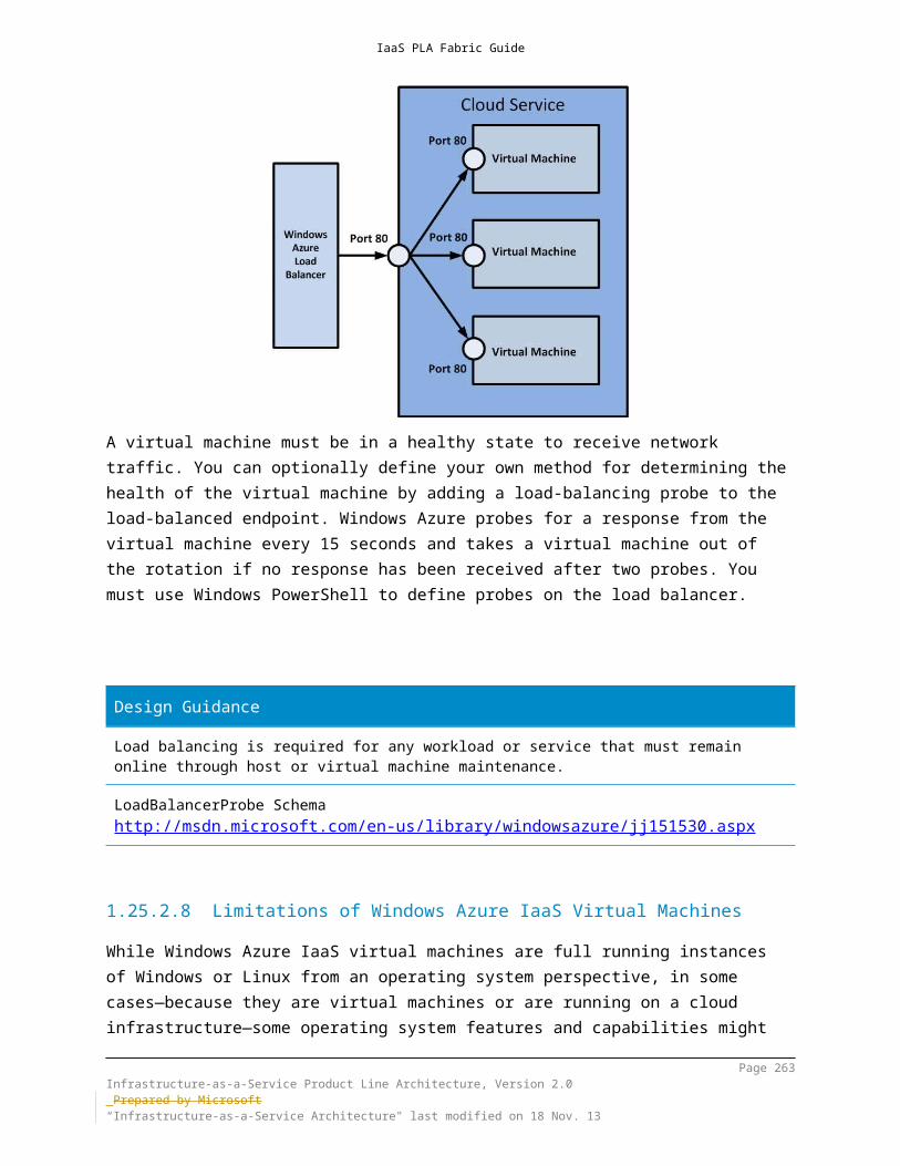
IaaS PLA Fabric Guide
Design Guidanceof the design process.Windows Server 2012 R2 provides the new Hyper-V replica feature, which has a significant impact on storage design depending on how many VMs will be replicated. While the replication traffic happens over the LAN, both sides must have enough storage bandwidth and capacity to run the specified VMs.Storage design should also be performed using the concept of scale-units. If the scale-unit is a host cluster of a certain size, that design should include storage connectivity and port requirements as well as an expected capacity utilization profile to ensure that the storage infrastructure (the Windows scale-out file clusters) can accommodate additional scale-units in the future, or have the ability to be expanded without a full re-architecture.References:
http://blogs.technet.com/b/josebda/archive/2012/08/26/updated-links-on- windows-server-2012-file-server-and-smb-3-0.aspx
http://blogs.technet.com/b/josebda/archive/2012/10/08/windows-server-2012- file-servers-and-smb-3-0-simpler-and-easier-by-design.aspx
Page 263Infrastructure-as-a-Service Product Line Architecture, Version 2.0 Prepared by Microsoft“Infrastructure-as-a-Service Architecture" last modified on 4 Dec. 13

IaaS PLA Fabric Guide
16 Multi-Tenant DesignsIn many private cloud scenarios, and nearly all hosting scenarios, a multi-tenant infrastructure is required. This section illustrates how a multi-tenant fabric infrastructure can be created by using Windows Server 2012 R2 and the technologies described in the fabric architecture guide. The term “multi-tenant” is fairly general. In general, multi-tenancy implies multiple non-related consumers or customers of a set of services. Within a single organization, this could be multiple business units with resources and data that must remain separate for legal or compliance reasons. Most hosting companies require multi-tenancy as a core attribute of their business model. This might include a dedicated physical infrastructure for each hosted customer or a logical segmentation of a shared infrastructure by using software-defined technologies.
16.1 Requirements GatheringThe design of a multi-tenant fabric must begin with a careful analysis of the business requirements, which will drive the design. In many cases, legal or compliance requirements drive the design approach, which means that a team of several disciplines (for example, business, technical, and legal) should participate in the requirements gathering phase. If specific legal or compliance regimes are required, a plan to ensure compliance and ongoing auditing (internal or third party) should be implemented.To organize the requirements gathering process, an “outside in” approach can be helpful. For hosted services, the end customer or consumer is outside of the hosting organization. Requirements gathering can begin by taking on the persona of the consumer and determining how the consumer will become aware of and be able to request access hosted services. Then consider multiple consumers, and ask the following questions:
Will consumers use accounts that the host creates or accounts that they use internally to access services?
Is one consumer allowed to be aware of other consumer’s identities, or is a separation required?
Moving further into the “outside in” process, determine whether legal or compliance concerns require dedicated resources for each consumer:
Can multiple consumers share a physical infrastructure? Can traffic from multiple consumers share a common network? Can software-defined isolation meet the requirements?
Page 264Infrastructure-as-a-Service Product Line Architecture, Version 2.0 Prepared by Microsoft“Infrastructure-as-a-Service Architecture" last modified on 4 Dec. 13

IaaS PLA Fabric Guide
How far into the infrastructure must authentication, authorization, and accounting be maintained for each consumer (for example, only at the database level, or including the disks and LUNs that are used by the consumer in the infrastructure)?
The following list provides a sample of the types of design and segmentation options that might be considered as part of a multi-tenant infrastructure:
Physical separation by customer (dedicated hosts, network, storage) Logical separation by customer (shared physical infrastructure with logical
segmentation) Data separation (such as dedicated databases and LUNs) Network separation (VLANs or private VLANs) Performance separation by customer (shared infrastructure but guaranteed
capacity or QoS)The remainder of this section describes multi-tenancy options at the fabric level and how those technologies can be combined to enable a multi-tenant fabric.
16.2 Infrastructure RequirementsThe aforementioned requirements gathering process should result in a clear direction and set of mandatory attributes that the fabric architecture must contain. The first key decision is whether a shared storage infrastructure or dedicated storage per tenant is required. For a host, driving toward as much shared infrastructure as possible is typically a business imperative, but there can be cases where it is prohibited.As mentioned in the previous storage sections in the fabric architecture guide, Windows Server 2012 R2 supports a range of traditional storage technologies such as JBOD, iSCSI/Fiber Channel SAN, and converged technologies such as FCOE. In addition, the new capabilities of storage spaces, cluster shared volumes, storage spaces tiering and scale-out file clusters present a potentially lower cost solution for advanced storage infrastructures. The shared versus dedicated storage infrastructure requirement drives a significant portion of the design process. If dedicated storage infrastructures per tenant are required, appropriate sizing and minimization of cost are paramount. It can be difficult to scale down traditional SAN approaches to a large number of small- or medium-sized tenants. In this case, the Scale-Out File Cluster and Storage Spaces approach, which uses shared SAS JBOD, can scale down cost effectively to a pair of file servers and a single SAS tray.
Page 265Infrastructure-as-a-Service Product Line Architecture, Version 2.0 Prepared by Microsoft“Infrastructure-as-a-Service Architecture" last modified on 4 Dec. 13

IaaS PLA Fabric Guide
Figure 40 Shared SAS storage
On the other end of the spectrum, if shared but logically segmented storage is an option, nearly all storage options become potentially relevant. Traditional Fiber Channel and iSCSI SANs have evolved to provide a range of capabilities to support multi-tenant environments through technologies such as zoning, masking, and virtual SANs. With the scalability enhancements in Windows Server 2012 R2 in the storage stack, large-scale shared storage infrastructures that use the Scale-Out File Cluster and Storage Spaces can also be a cost effective choice.Although previous sections discussed architecture and scalability, the section highlights technologies for storage security and isolation in multi-tenant environments.
16.3 Multi-Tenant Storage Considerations16.3.1 SMB 3.0The Server Message Block (SMB) protocol is a network file sharing protocol that allows applications on a computer to read and write to files and to request services from server programs in a computer network. The SMB protocol can be used on top of its TCP/IP protocol or other network protocols. By using the SMB protocol, an application (or the user of an application) can access files or other resources on a remote server. This allows users to read, create, and update files on the remote server. The application can also communicate with any server program that is set up to receive an SMB client request. Windows Server 2012 R2 provides the following practical ways to use the SMB 3.0 protocol:
Page 266Infrastructure-as-a-Service Product Line Architecture, Version 2.0 Prepared by Microsoft“Infrastructure-as-a-Service Architecture" last modified on 4 Dec. 13

IaaS PLA Fabric Guide
File storage for virtualization (Hyper-V over SMB): Hyper-V can store virtual machine files (such as configuration files, virtual hard disk (VHD) files, and snapshots) in file shares over the SMB 3.0 protocol. This can be used for stand-alone file servers and for clustered file servers that use Hyper-V with shared file storage for the cluster.
Microsoft SQL Server over SMB: SQL Server can store user database files on SMB file shares. Currently, this is supported with SQL Server 2008 R2 for stand-alone servers.
Traditional storage for end-user data: The SMB 3.0 protocol provides enhancements to the information worker (client) workloads. These enhancements include reducing the application latencies experienced by branch office users when accessing data over wide area networks (WAN) and protecting data from eavesdropping attacks.
16.3.1.1 SMB Encryption A security concern for data that traverses untrusted networks is that it is prone to eavesdropping attacks. Existing solutions for this issue typically use IPsec, WAN accelerators, or other dedicated hardware solutions. However, these solutions are expensive to set up and maintain. Windows Server 2012 R2 includes encryption that is built-in to the SMB protocol. This allows end-to-end data protection from snooping attacks with no additional deployment costs. You have the flexibility to decide whether the entire server or only specific shares should be enabled for encryption. SMB Encryption is also relevant to server application workloads if the application data is on a file server and it traverses untrusted networks. With this feature, data security is maintained while it is on the wire.
16.3.1.2 Cluster Shared Volumes By using Cluster Shared Volumes (CSVs), you can unify storage access into a single namespace for ease of management. A common namespace folder that contains all the CSVs in the failover cluster is created at the path C:\ClusterStorage\. All cluster nodes can access a CSV at the same time, regardless of the number of servers, the number of JBOD enclosures, or the number of provisioned virtual disks. This unified namespace enables high availability workloads to transparently fail over to another server if a server failure occurs. It also enables you to easily take a server offline for maintenance.Clustered storage spaces can help protect against the following risks:
Physical disk failures: When you deploy a clustered storage space, protection against physical disk failures is provided by creating storage spaces with the mirror resiliency type. Additionally, mirror spaces use “dirty region tracking” to track modifications to the disks in the pool. When the
Page 267Infrastructure-as-a-Service Product Line Architecture, Version 2.0 Prepared by Microsoft“Infrastructure-as-a-Service Architecture" last modified on 4 Dec. 13

IaaS PLA Fabric Guide
system resumes from a power fault or a hard reset event and the spaces are brought back online, dirty region tracking creates consistency among the disks in the pool.
Data access failures: If you have redundancy at all levels, you can protect against failed components, such as a failed cable from the enclosure to the server, a failed SAS adapter, power faults, or failure of a JBOD enclosure. For example, in an enterprise deployment, you should have redundant SAS adapters, SAS I/O modules, and power supplies. To protect against complete disk enclosure failure, you can use redundant JBOD enclosures.
Data corruptions and volume unavailability: The NTFS file system and the Resilient File System (ReFS) help protect against corruption. For NTFS, improvements to the Chkdsk tool in Windows Server 2012 R2 can greatly improve availability. If you deploy highly available file servers, you can use ReFS to enable high levels of scalability and data integrity regardless of hardware or software failures.
Server node failures: Through the Failover Clustering feature in Windows Server 2012 R2, you can provide high availability for the underlying storage and workloads. This helps protect against server failure and enables you to take a server offline for maintenance without service interruption.
The following are some of the technologies in Windows Server 2012 R2 that can enable multi-tenant architectures.
File storage for virtualization (Hyper-V over SMB): Hyper-V can store virtual machine files (such as configuration files, virtual hard disk (VHD) files, and snapshots) in file shares over the SMB 3.0 protocol. This can be used for stand-alone file servers and for clustered file servers that use Hyper-V with shared file storage for the cluster.
Microsoft SQL Server over SMB: SQL Server can store user database files on SMB file shares. Currently, this is supported with SQL Server 2008 R2 for stand-alone servers.
Storage can be made visible to only a subset of nodes: Enables cluster deployments that contain application and data nodes.
Integration with Storage Spaces: Allows virtualization of cluster storage on groups of inexpensive disks. The Storage Spaces feature in Windows Server 2012 R2 can integrate with CSVs to permit scale-out access to data.
16.3.1.3 Security and Storage Access ControlA solution that uses file clusters, storage spaces, and SMB 3.0 in Windows Server 2012 R2 eases the management of large scale storage solutions because nearly all the setup and configuration is Windows based with associated Windows PowerShell support. If desired, particular storage can be made visible to only a subset of nodes in the file cluster. This can be used in some scenarios to leverage the cost and
Page 268Infrastructure-as-a-Service Product Line Architecture, Version 2.0 Prepared by Microsoft“Infrastructure-as-a-Service Architecture" last modified on 4 Dec. 13
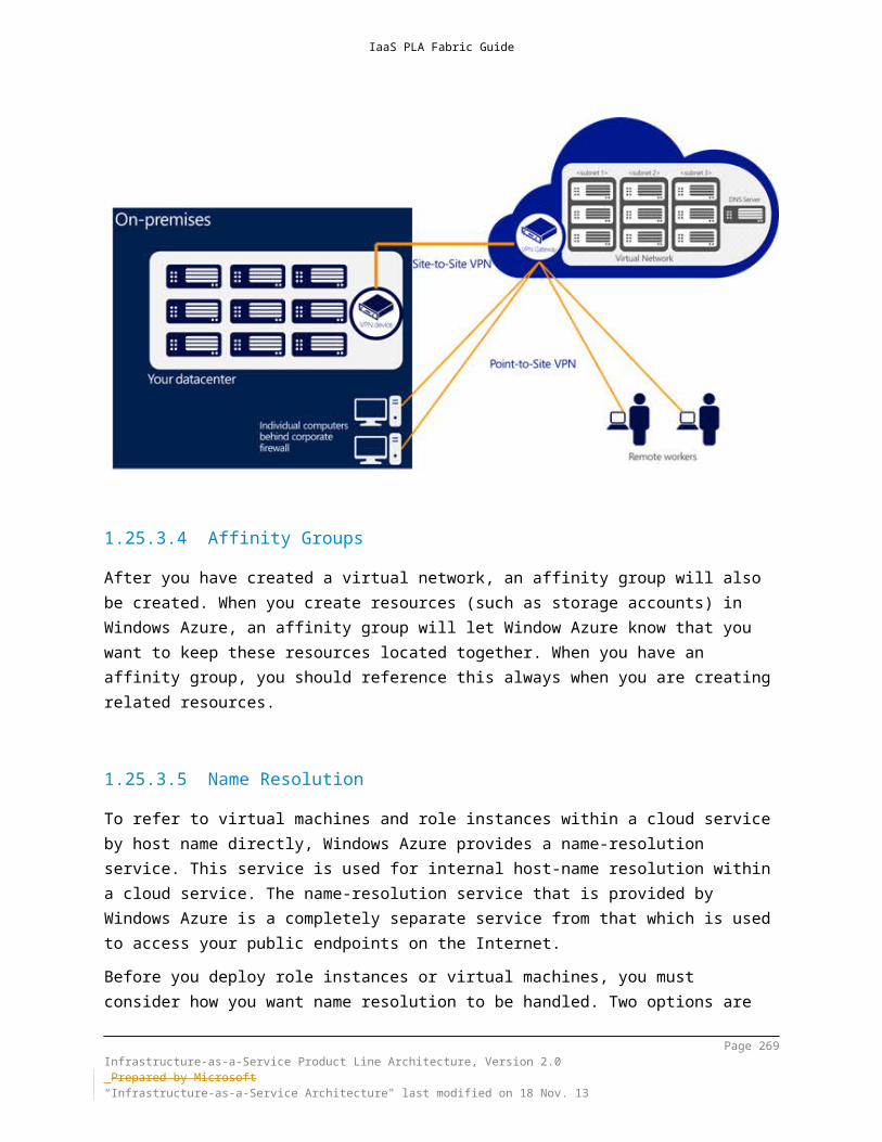
IaaS PLA Fabric Guide
management advantage of larger shared clusters, and to segment those clusters for performance or access purposes. Additionally, at various levels of the storage stack (for example, shares, CSVs, and storage spaces), access control lists can be applied. In a multi-tenant scenario, this means that the full storage infrastructure can be shared and managed centrally and that dedicated and controlled access to segments of the storage infrastructure can be designed. A particular customer could have LUNs, storage pools, storage spaces, cluster shared volumes, and shares dedicated to them, and access control lists can ensure that only that tenant has access to them.Additionally, by using SMB Encryption, all access to the file-based storage can be encrypted to protect against tampering and eavesdropping attacks. The biggest benefit of using SMB Encryption over more general solutions (such as IPSec) is that there are no deployment requirements or costs beyond changing the SMB server settings. The encryption algorithm used is AES-CCM, which also provides data integrity validation (signing).
16.4 Multi-Tenant Network ConsiderationsThe network infrastructure is one of the most common and critical layers of the fabric where multi-tenant design is implemented. It is also an area of rapid innovation because the traditional methods of traffic segmentation, such as VLANs and port ACLs, are beginning to show their age, and they are unable to keep up with highly virtualized, large scale hosting data centers and hybrid cloud scenarios.The following sections describe the range of technologies that are provided in Windows Server 2012 R2 for building modern, secure, multi-tenant network infrastructures.
16.4.1 Windows Network VirtualizationHyper-V Network Virtualization provides the concept of a virtual network that is independent of the underlying physical network. With this concept of virtual networks, which are composed of one or more virtual subnets, the exact physical location of an IP subnet is decoupled from the virtual network topology.As a result, customers can easily move their subnets to the cloud while preserving their existing IP addresses and topology in the cloud so that existing services continue to work unaware of the physical location of the subnets.Hyper-V Network Virtualization provides policy-based, software-controlled network virtualization that reduces the management overhead that is faced by enterprises when they expand dedicated IaaS clouds, and it provides cloud hosts with better flexibility and scalability for managing virtual machines to achieve higher resource utilization.
Page 269Infrastructure-as-a-Service Product Line Architecture, Version 2.0 Prepared by Microsoft“Infrastructure-as-a-Service Architecture" last modified on 4 Dec. 13

IaaS PLA Fabric Guide
An IaaS scenario that has multiple virtual machines from different organizational divisions (dedicated cloud) or different customers (hosted cloud) requires secure isolation. Virtual local area networks (VLANs), can present significant disadvantages in this scenario.For more information, see Hyper-V Network Virtualization Overview in the TechNet Library.VLANs Currently, VLANs are the mechanism that most organizations use to support address space reuse and tenant isolation. A VLAN uses explicit tagging (VLAN ID) in the Ethernet frame headers, and it relies on Ethernet switches to enforce isolation and restrict traffic to network nodes with the same VLAN ID. As described before, there are disadvantages with VLANs which introduce challenges in large-scale multi-tenant environments.IP address assignment In addition to the disadvantages that are presented by VLANs, virtual machine IP address assignment presents issues, which include:
Physical locations in data center network infrastructure determine virtual machine IP addresses. As a result, moving to the cloud typically requires rationalizing and possibly IP addresses across workloads and tenants.
Policies are tied to IP addresses, such as firewall rules, resource discovery, and directory services. Changing IP addresses requires updating all the associated policies.
Virtual machine deployment and traffic isolation are dependent on the topology.
When data center network administrators plan the physical layout of the data center, they must make decisions about where subnets will be physically placed and routed. These decisions are based on IP and Ethernet technology that influence the potential IP addresses that are allowed for virtual machines running on a given server or a blade that is connected to a particular rack in the data center. When a virtual machine is provisioned and placed in the data center, it must adhere to these choices and restrictions regarding the IP address. Therefore, the typical result is that the data center administrators assign new IP addresses to the virtual machines.The issue with this requirement is that in addition to being an address, there is semantic information associated with an IP address. For instance, one subnet may contain given services or be in a distinct physical location. Firewall rules, access control policies, and IPsec security associations are commonly associated with IP addresses. Changing IP addresses forces the virtual machine owners to adjust all their policies that were based on the original IP address. This renumbering overhead is so high that many enterprises choose to deploy only new services to the cloud, leaving legacy applications alone.Hyper-V Network Virtualization decouples virtual networks for customer virtual machines from the physical network infrastructure. As a result, it enables customer
Page 270Infrastructure-as-a-Service Product Line Architecture, Version 2.0 Prepared by Microsoft“Infrastructure-as-a-Service Architecture" last modified on 4 Dec. 13

IaaS PLA Fabric Guide
virtual machines to maintain their original IP addresses, while allowing data center administrators to provision customer virtual machines anywhere in the data center without reconfiguring physical IP addresses or VLAN IDs.Each virtual network adapter in Hyper-V Network Virtualization is associated with two IP addresses:
Customer Address (CA): The IP address that is assigned by the customer, based on their intranet infrastructure. This address enables the customer to exchange network traffic with the virtual machine as if it had not been moved to a public or private cloud. The CA is visible to the virtual machine and reachable by the customer.
Provider Address (PA): The IP address that is assigned by the host or the data center administrators, based on their physical network infrastructure. The PA appears in the packets on the network that are exchanged with the Hyper-V server that is hosting the virtual machine. The PA is visible on the physical network, but not to the virtual machine.
The CAs maintain the customer's network topology, which is virtualized and decoupled from the actual underlying physical network topology and addresses, as implemented by the PAs. Figure 44 shows the conceptual relationship between virtual machine CAs and network infrastructure PAs as a result of network virtualization.
Figure 41 Conceptual relationship between CAs and PAs
Key aspects of network virtualization in this scenario includes: Each virtual machine CA is mapped to a physical host PA. Virtual machines send data packets in the CA spaces, which are put into an
“envelope” with a PA source and destination pair based on the mapping.
Page 271Infrastructure-as-a-Service Product Line Architecture, Version 2.0 Prepared by Microsoft“Infrastructure-as-a-Service Architecture" last modified on 4 Dec. 13

IaaS PLA Fabric Guide
The CA-PA mappings must allow the hosts to differentiate packets for different customer virtual machines.
As a result, the mechanism used to virtualize the network is to virtualize the network addresses used by the virtual machines. Hyper-V Network Virtualization supports the following modes to virtualize the IP address:
Generic Routing Encapsulation The network virtualization generic routing encapsulation (NVGRE) is part of the tunnel header. This mode is intended for the majority of data centers that deploy Hyper-V Network Virtualization. In NVGRE, the virtual machine’s packet is encapsulated inside another packet. The header of this new packet has the appropriate source and destination PA IP addresses in addition to the virtual subnet ID, which is stored in the Key field of the GRE header.
IP Rewrite In this mode, the source and the destination CA IP addresses are rewritten with the corresponding PA addresses as the packets leave the end host. Similarly, when virtual subnet packets enter the end host, the PA IP addresses are rewritten with appropriate CA addresses before being delivered to the virtual machines. IP Rewrite is targeted for special scenarios where the virtual machine workloads require or consume very high bandwidth throughput (~10 Gbps) on existing hardware. IP Rewrite is intended for special scenarios where virtual machines require ~10 Gbps bandwidth today, and the customer cannot wait for NVGRE-aware hardware.
16.4.2 Hyper-V Extensible SwitchThe Hyper-V Virtual Switch is a software-based, layer-2 network switch that is available in Hyper-V Manager when you install the Hyper-V server role. The switch includes programmatically managed and extensible capabilities to connect virtual machines to virtual networks and to the physical network. In addition, Hyper-V Virtual Switch provides policy enforcement for security, isolation, and service levels. The Hyper-V Virtual Switch in Windows Server 2012 R2 introduces several features and enhanced capabilities for tenant isolation, traffic shaping, protection against malicious virtual machines, and simplified troubleshooting.With built-in support for Network Device Interface Specification (NDIS) filter drivers and Windows Filtering Platform (WFP) callout drivers, the Hyper-V virtual switch enables independent software vendors (ISVs) to create extensible plug-ins (known as virtual switch extensions) that can provide enhanced networking and security capabilities. Virtual switch extensions that you add to the Hyper-V virtual switch are listed in the Virtual Switch Manager feature of Hyper-V Manager.The capabilities provided in the Hyper-V virtual switch mean that organizations have more options to enforce tenant isolation, to shape and control network traffic, and to employ protective measures against malicious virtual machines.
Page 272Infrastructure-as-a-Service Product Line Architecture, Version 2.0 Prepared by Microsoft“Infrastructure-as-a-Service Architecture" last modified on 4 Dec. 13

IaaS PLA Fabric Guide
Some of the principal features that are included in the Hyper-V virtual switch are: ARP and Neighbor Discovery spoofing protection: Provides protection
against a malicious virtual machine by sing Address Resolution Protocol (ARP) spoofing to steal IP addresses from other virtual machines. Provides protection against attacks that can be launched for IPv6 by using Neighbor Discovery spoofing.
DHCP Guard protection: Protects against a malicious virtual machine representing itself as a Dynamic Host Configuration Protocol (DHCP) server for man-in-the-middle attacks.
Port ACLs: Provides traffic filtering, based on Media Access Control (MAC) or Internet Protocol (IP) addresses and ranges, which enables you to set up virtual network isolation.
Trunk mode to virtual machines: Enables administrators to set up a specific virtual machine as a virtual appliance, and then direct traffic from various VLANs to that virtual machine.
Network traffic monitoring: Enables administrators to review traffic that is traversing the network switch.
Isolated (private) VLAN: Enables administrators to segregate traffic on multiple VLANs, to more easily establish isolated tenant communities.
The features listed above can be combined to deliver a complete multi-tenant network design.
16.4.3 Example Network DesignIn Hyper-V Network Virtualization, a customer is defined as the owner of a group of virtual machines that are deployed in a data center. A customer can be a corporation or enterprise in a multi-tenant public data center, or a division or business unit within a private data center. Each customer can have one or more customer networks in the data center, and each customer network consists of one or more customer networks with virtual subnets.Customer network
Each customer network consists of one or more virtual subnets. A customer network forms an isolation boundary where the virtual machines within a customer network can communicate with each other. As a result, virtual subnets in the same customer network must not use overlapping IP address prefixes.
Each customer network has a routing domain, which identifies the customer network. The routing domain ID, which identifies the customer network, is assigned by data center administrators or data center management software, such as System Center Virtual Machine Manager (VMM). The routing domain ID has a GUID format, for example, “{11111111-2222-3333-4444-000000000000}”.
Page 273Infrastructure-as-a-Service Product Line Architecture, Version 2.0 Prepared by Microsoft“Infrastructure-as-a-Service Architecture" last modified on 4 Dec. 13

IaaS PLA Fabric Guide
Virtual subnets A virtual subnet implements the Layer 3 IP subnet semantics for the virtual
machines in the same virtual subnet. The virtual subnet is a broadcast domain (similar to a VLAN). Virtual machines in the same virtual subnet must use the same IP prefix, although a single virtual subnet can accommodate an IPv4 and an IPv6 prefix simultaneously.
Each virtual subnet belongs to a single customer network (with a routing domain ID), and it is assigned a unique virtual subnet ID (VSID). The VSID is universally unique and may be in the range 4096 to 2^24-2).
A key advantage of the customer network and routing domain is that it allows customers to bring their network topologies to the cloud. The following diagram shows an example where the Blue Corp has two separate networks, the R&D Net and the Sales Net. Because these networks have different routing domain IDs, they cannot interact with each other. That is, Blue R&D Net is isolated from Blue Sales Net, even though both are owned by Blue Corp. Blue R&D Net contains three virtual subnets. Note that the routing domain ID and VSID are unique within a data center.
Figure 42 Example Hoster/Service Provider data center network design
In this example, the virtual machines with VSID 5001 can have their packets routed or forwarded by Hyper-V Network Virtualization to virtual machines with VSID 5002 or VSID 5003. Before delivering the packet to the virtual switch, Hyper-V Network Virtualization will update the VSID of the incoming packet to the VSID of the destination virtual machine. This will only happen if both VSIDs are in the same routing domain ID. If the VSID that is associated with the packet does not match the VSID of the destination virtual machine, the packet will be dropped. Therefore, virtual network adapters with RDID1 cannot send packets to virtual network adapters with RDID2.
Page 274Infrastructure-as-a-Service Product Line Architecture, Version 2.0 Prepared by Microsoft“Infrastructure-as-a-Service Architecture" last modified on 4 Dec. 13

IaaS PLA Fabric Guide
Each virtual subnet defines a Layer 3 IP subnet and a Layer 2 (L2) broadcast domain boundary similar to a VLAN. When a virtual machine broadcasts a packet, this broadcast is limited to the virtual machines that are attached to switch ports with the same VSID. Each VSID can be associated with a multicast address in the PA. All broadcast traffic for a VSID is sent on this multicast address.In addition to being a broadcast domain, the VSID provides isolation. A virtual network adapter in Hyper-V Network Virtualization is connected to a Hyper-V switch port that has a VSID ACL. If a packet arrives on this Hyper-V virtual switch port with a different VSID, the packet is dropped. Packets will only be delivered on a Hyper-V virtual switch port if the VSID of the packet matches the VSID of the virtual switch port. This is the reason that packets flowing from VSID 5001 to 5003 must modify the VSID in the packet before delivery to the destination virtual machine.If the Hyper-V virtual switch port does not have a VSID ACL, the virtual network adapter that is attached to that virtual switch port is not part of a Hyper-V Network Virtualization virtual subnet. Packets that are sent from a virtual network adapter that does not have a VSID ACL will pass unmodified through the Hyper-V Network Virtualization.When a virtual machine sends a packet, the VSID of the Hyper-V virtual switch port is associated with this packet in the out-of-band (OOB) data. If generic routing encapsulation (GRE) is the IP virtualization mechanism, the GRE Key field of the encapsulated packet contains the VSID. On the receiving side, Hyper-V Network Virtualization delivers the VSID in the OOB and the de-capsulated packet to the Hyper-V virtual switch. If IP Rewrite is the IP virtualization mechanism, and the packet is destined for a different physical host, the IP addresses are changed from CA addresses to PA addresses, and the VSID in the OOB is dropped. Hyper-V Network Virtualization verifies a policy and adds the VSID to the OOB data before the packet is passed to the Hyper-V virtual switch.
16.5 Multi-Tenant Compute ConsiderationsSimilar to storage and network, the compute layer of the fabric can be dedicated per tenant or shared across multiple tenants. That decision greatly impacts the design of the compute layer. Two primary decisions are required to begin the design process:
Will the compute layer be shared between multiple tenants? Will the compute infrastructure provide high availability by using failover
clustering?This leads to four high-level design options:
Dedicated stand-alone Hyper-V servers Shared stand-along Hyper-V servers Dedicated Hyper-V failover clusters
Page 275Infrastructure-as-a-Service Product Line Architecture, Version 2.0 Prepared by Microsoft“Infrastructure-as-a-Service Architecture" last modified on 4 Dec. 13

IaaS PLA Fabric Guide
Shared Hyper-V failover clustersShared-nothing live migration in Windows Server 2012 R2 enables stand-alone Hyper-V servers to be a viable option when high availability of the running virtual machines is not a requirement. Shared-nothing live migration enables virtual machines to be moved from any Hyper-V host running Windows Server 2012 R2 to another, with nothing but a network connection required—it does not require shared storage. For hosts that are delivering stateless application and web hosting services, this may be an option. The shared-nothing live migration feature would enable the host to move virtual machines and evacuate hosts for patching without causing downtime to the running virtual machines. However, stand-alone hosts do not provide virtual machine high availability, so if the host fails, the virtual machines are not automatically started on another host.The decision of using a dedicated vs. a shared Hyper-V host is primarily driven by the compliance or business model requirements discussed previously.
16.5.1 Hyper-V The Hyper-V role enables you to create and manage a virtualized computing environment by using the virtualization technology that is built in to Windows Server 2012 R2. Installing the Hyper-V role installs the required components and optionally installs management tools. The required components include the Windows hypervisor, Hyper-V Virtual Machine Management Service, the virtualization WMI provider, and other virtualization components such as the virtual machine bus (VMbus), virtualization service provider (VSP) and virtual infrastructure driver (VID). The management tools for the Hyper-V role consist of:
GUI-based management tools: Hyper-V Manager, a Microsoft Management Console (MMC) snap-in, and Virtual Machine Connection, which provides access to the video output of a virtual machine so you can interact with the virtual machine.
Hyper-V-specific cmdlets for Windows PowerShell. Windows Server 2012 includes a Hyper-V module, which provides command-line access to all the functionality that is available in the GUI, in addition to functionality that is not available through the GUI.
The scalability and availability improvements in Hyper-V allow for significantly larger clusters and greater consolidation ratios, which are key to the cost of ownership for enterprises and hosts. Hyper-V in Windows Server 2012 R2 supports significantly larger configurations of virtual and physical components than in previous releases of Hyper-V. This increased capacity enables you to run Hyper-V on large physical computers and to virtualize high-performance, scale-up workloads.
Page 276Infrastructure-as-a-Service Product Line Architecture, Version 2.0 Prepared by Microsoft“Infrastructure-as-a-Service Architecture" last modified on 4 Dec. 13

IaaS PLA Fabric Guide
Hyper-V provides a multitude of options for segmentation and isolation of virtual machines that are running on the same server. This is critical for shared Hyper-V server and cluster scenarios where multiple tenants will host their virtual machines on the same servers. By design, Hyper-V ensures isolation of memory, VMBus, and other system and hypervisor constructs between all virtual machines on a host.
16.5.2 Failover ClusteringFailover clusters provide high availability and scalability to many server workloads. Failover Clustering in Windows Server 2012 R2 supports increased scalability, continuously available file-based server application storage, easier management, faster failover, automatic rebalancing and more flexible architectures for failover clusters. For the purposes of a multi-tenant design, Hyper-V clusters can be used in conjunction with the aforementioned scale-out file server clusters for an end-to-end Microsoft solution for storage, network, and compute architectures.
16.5.3 Resource MeteringService Providers and enterprises deploying private clouds need tools to charge back business units that they support while providing the business units with the right amount of resources to match their needs. For hosting providers, it is equally important to issue chargebacks based on the amount of usage by each customer.To implement advanced billing strategies that measure the assigned capacity of a resource and its actual usage, earlier versions of Hyper-V required users to develop their own chargeback solutions that polled and aggregated performance counters. These solutions could be expensive to develop and sometimes led to loss of historical data.To assist with more accurate, streamlined chargebacks while protecting historical information, Hyper-V in Windows Server 2012 supports Resource Metering, a feature that allows customers to create cost-effective, usage-based billing solutions. With this feature, service providers can choose the best billing strategy for their business model, and independent software vendors can develop more reliable, end-to-end chargeback solutions on top of Hyper-V.
16.5.4 ManagementAlthough this guide deals only with fabric architecture and not the more comprehensive topic of fabric management by using System Center 2012 R2, there are significant management and automation of multi-server, multi-tenant environments enabled by Windows Server 2012 R2 technologies.Windows Server 2012 R2 delivers significant management efficiency with broader automation of common management tasks and a path toward full out-of-band
Page 277Infrastructure-as-a-Service Product Line Architecture, Version 2.0 Prepared by Microsoft“Infrastructure-as-a-Service Architecture" last modified on 4 Dec. 13

IaaS PLA Fabric Guide
management automation. For example, Server Manager in Windows Server 2012 R2 enables multiple servers on the network to be managed effectively from a single computer. With the Windows PowerShell 3.0 command-line interface, Windows Server 2012 R2 provides a platform for robust, multi-machine automation for all elements of a data center, including servers, Windows operating systems, storage, and networking. It also provides centralized administration and management capabilities such as deploying roles and features remotely to physical and virtual servers, and deploying roles and features to virtual hard disks, even when they are offline.
Page 278Infrastructure-as-a-Service Product Line Architecture, Version 2.0 Prepared by Microsoft“Infrastructure-as-a-Service Architecture" last modified on 4 Dec. 13