infrared thermometers also known as pyrometers
TRANSCRIPT

15 Minute Break

Components of a Temperature Sensor
• The Optics collect & focus the emitted energy onto a detector. Types of lenses include glass, quartz, achromat, germanium, and zinc.
• The Filters optimize the operation of the sensor to selected energy wavelengths.
• The Detector converts the infrared energy signal into an electrical signal. Common detectors include Ge, Si, InGaAs, Thermopile, PbS, PbSe, InAs.
Temperature RangeSensor Type
OpticsWavelength
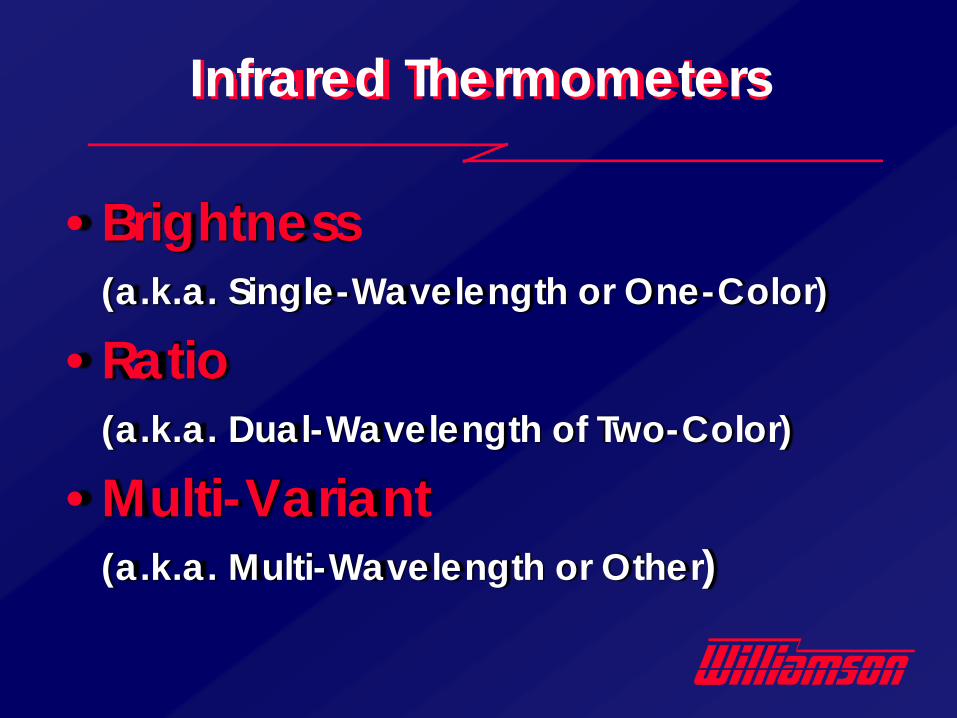
Infrared Thermometers
•Brightness(a.k.a. Single-Wavelength or One-Color)
•Ratio(a.k.a. Dual-Wavelength of Two-Color)
•Multi-Variant(a.k.a. Multi-Wavelength or Other)
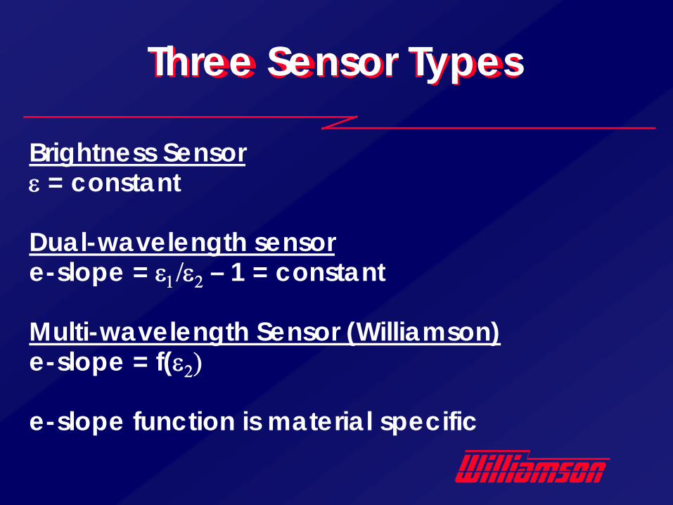
Three Sensor Types
Brightness Sensorε = constant
Dual-wavelength sensore-slope = ε1/ε2 – 1 = constant
Multi-wavelength Sensor (Williamson)e-slope = f(ε2)
e-slope function is material specific
Brightness Sensors
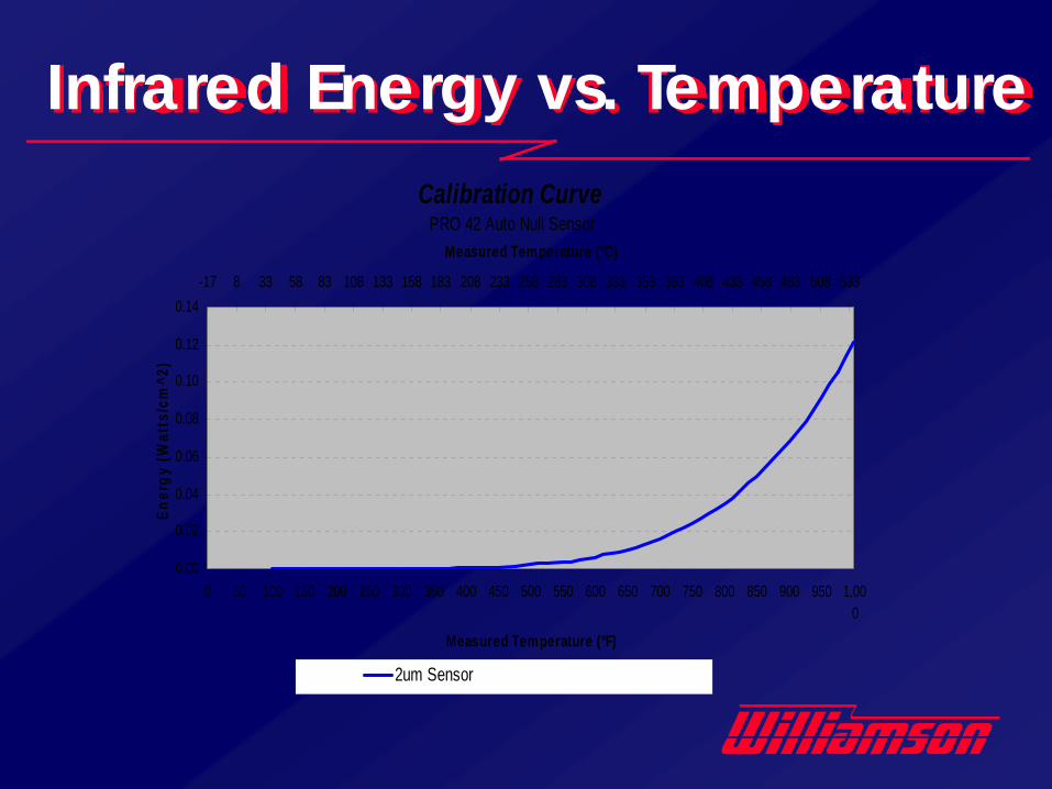
Infrared Energy vs. TemperatureCalibration Curve
PRO 42 Auto Null Sensor
0.00
0.02
0.04
0.06
0.08
0.10
0.12
0.14
0 50 100 150 200 250 300 350 400 450 500 550 600 650 700 750 800 850 900 950 1,000
Measured Temperature (°F)
Ener
gy (W
atts
/cm
^2)
-17 8 33 58 83 108 133 158 183 208 233 258 283 308 333 358 383 408 433 458 483 508 533
Measured Temperature (°C)
2um Sensor

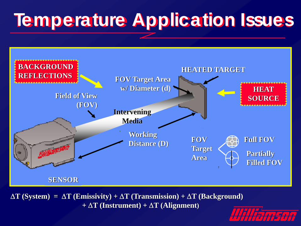
Temperature Application Issues
FOV TargetArea
Full FOV
Partially Filled FOV
FOV Target Areaw/ Diameter (d)
HEATED TARGETBACKGROUNDREFLECTIONS
Working Distance (D)
HEAT SOURCE
InterveningMedia
Field of View (FOV)
SENSOR
ΔT (System) = ΔT (Emissivity) + ΔT (Transmission) + ΔT (Background) + ΔT (Instrument) + ΔT (Alignment)
Brightness Sensors
• Tend to measure an average temperature value
• Are affected by changes in emissivity, optical obstruction & stray background energy
• Wavelength Matters!

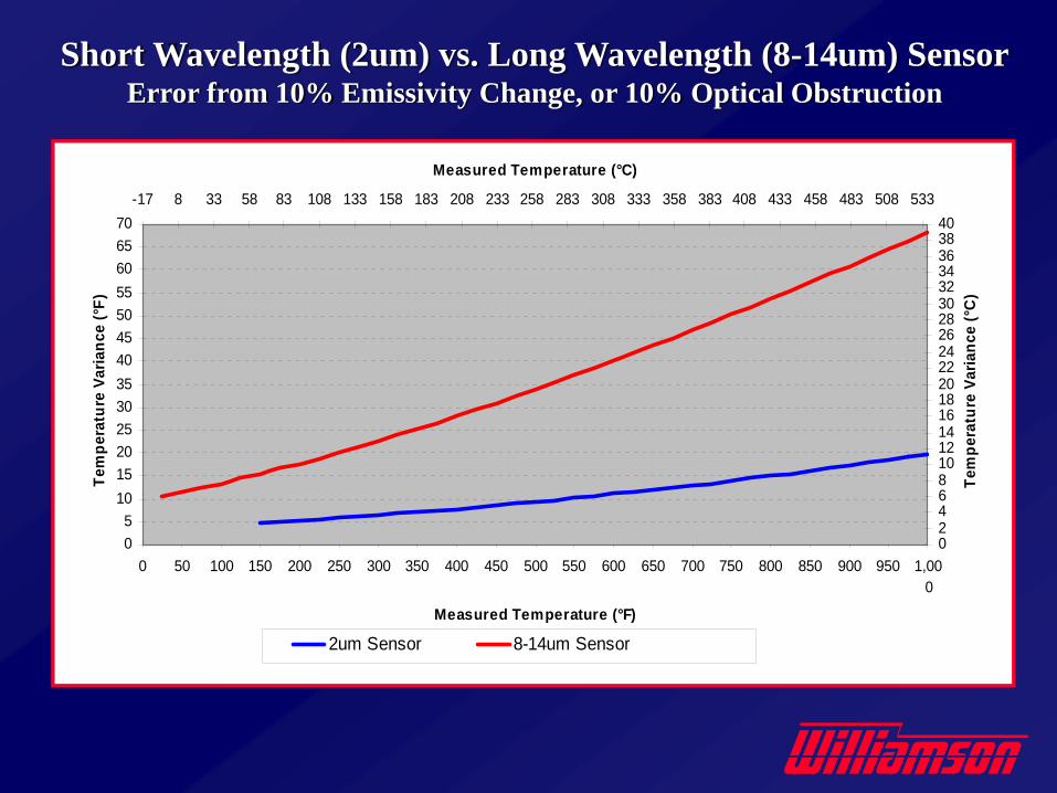
• Shorter Wavelengths are less sensitive to emissivity variation and optical obstruction.
• Shorter wavelength readings are more highly weighted towards the hottest temperature viewed & longer wavelengths are less sensitive to hot reflections.
• For low-emissivity materials, the emissivity is higher at a shorter wavelength, further reducing errors.
• Wavelength selection is critical for viewing through steam, flames and products of combustion, for avoiding IR heater interference, and for measuring coated products.
Why Wavelength Matters
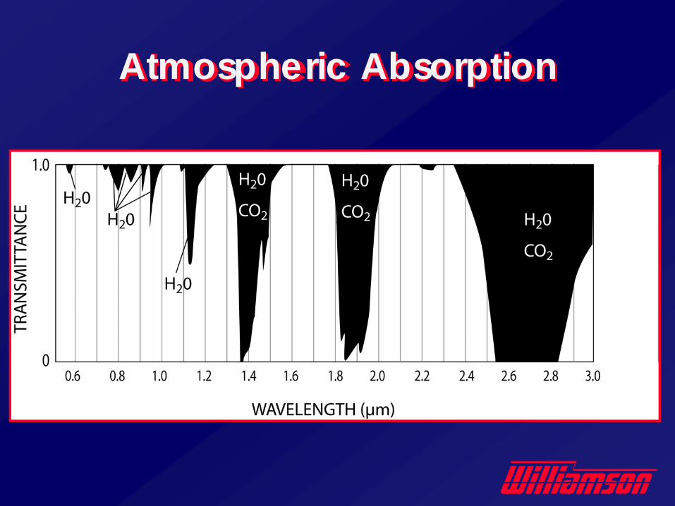
Atmospheric Absorption
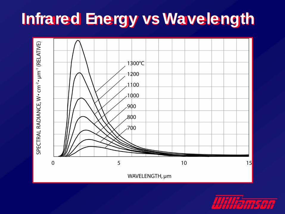
Infrared Energy vs Wavelength
05
10152025303540455055606570
0 50 100 150 200 250 300 350 400 450 500 550 600 650 700 750 800 850 900 950 1,000
Measured Temperature (°F)
Tem
pera
ture
Var
ianc
e (°
F)
0246810121416182022242628303234363840
-17 8 33 58 83 108 133 158 183 208 233 258 283 308 333 358 383 408 433 458 483 508 533
Measured Temperature (°C)
Tem
pera
ture
Var
ianc
e (°
C)
2um Sensor 8-14um Sensor
Short Wavelength (2um) vs. Long Wavelength (8-14um) SensorError from 10% Emissivity Change, or 10% Optical Obstruction
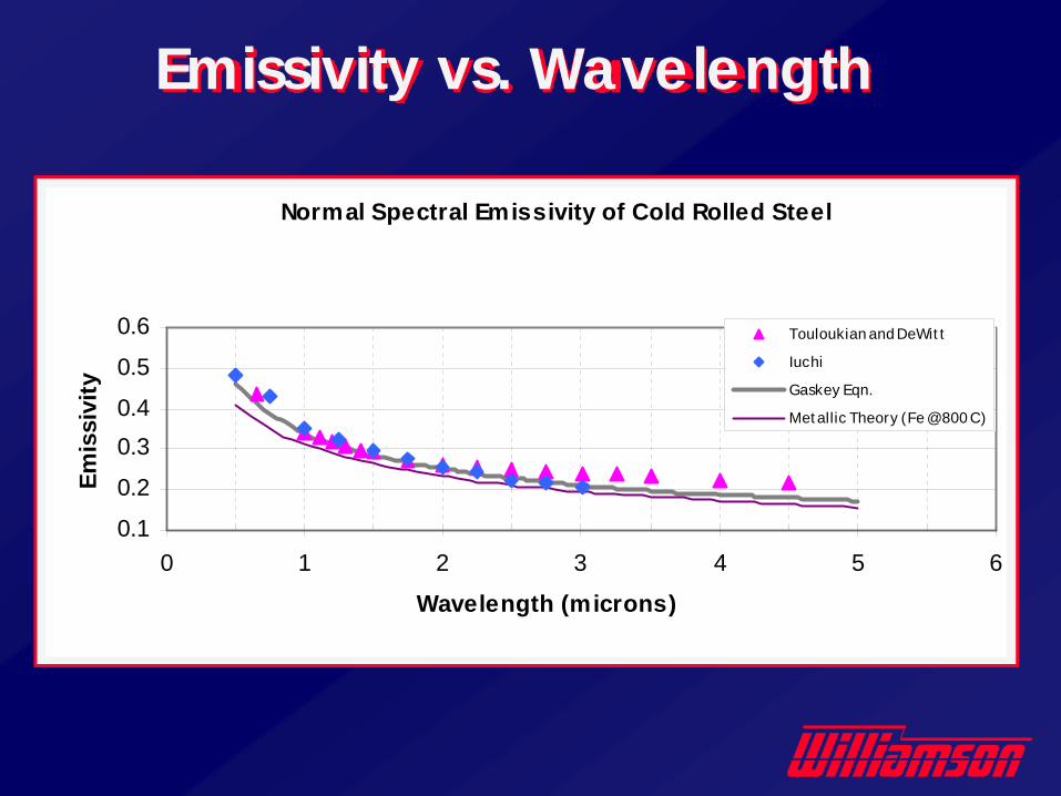
Normal Spectral Emissivity of Cold Rolled Steel
0.1
0.2
0.30.4
0.5
0.6
0 1 2 3 4 5 6
Wavelength (microns)
Emis
sivi
ty
Touloukian and DeWit t
Iuchi
Gaskey Eqn.
Met allic Theory (Fe @800 C)
Emissivity vs. Wavelength
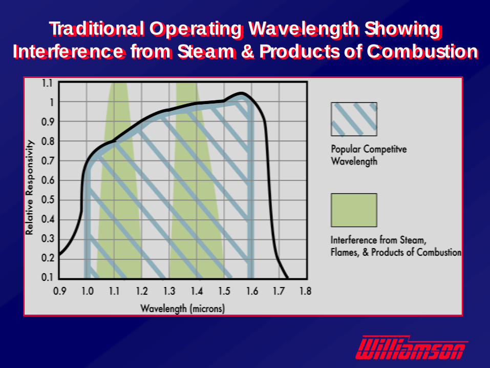
Traditional Operating Wavelength Showing Interference from Steam & Products of Combustion
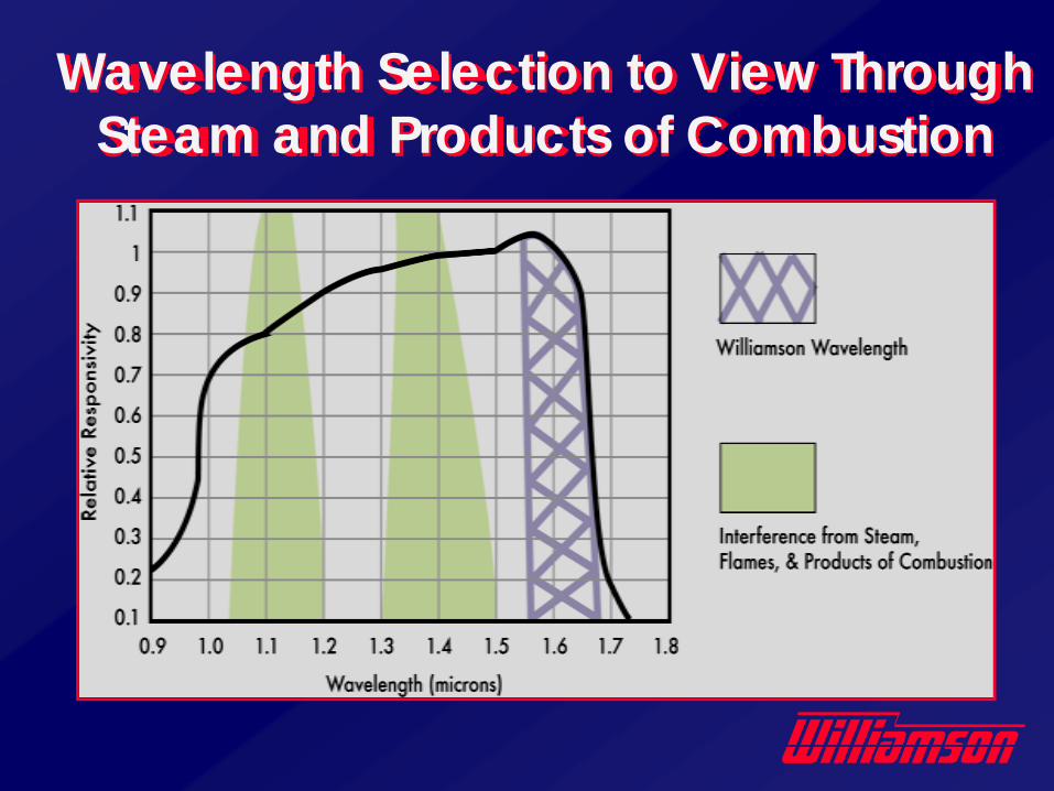
Wavelength Selection to View Through Steam and Products of Combustion
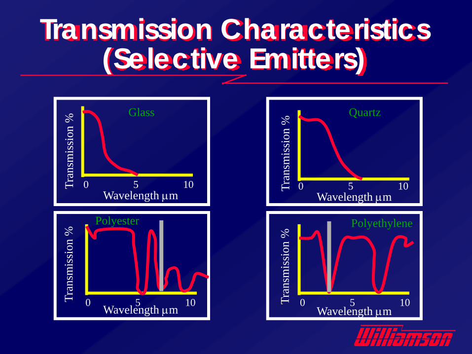
Transmission Characteristics (Selective Emitters)
Wavelength μm
Wavelength μm
Wavelength μm
Wavelength μm
Glass Quartz
Polyester Polyethylene
0 5 10
0 5 10
0 5 10
0 5 10
Tran
smis
sion
%Tr
ansm
issi
on %
Tran
smis
sion
%Tr
ansm
issi
on %
Brightness Wavelength Selection
• Use the shortest practical wavelength for most applications to minimize sensitivity to emissivity variance & optical obstruction.
• Use a specific wavelength to eliminate or minimize transmission or reflection issues (i.e. coatings, flames, products of combustion, water vapor, steam, water spray, plastics, glass, crystalline materials).
Compensation for Emissivity
• Single-wavelength sensors require a constant emissivity
• Select the shortest possible wavelength(1-2um) to minimize errors due to changes in emissivity
• An emissivity adjustment compensates for different emissivity values
• Many applications require repeatability, not absolute accuracy
Brightness Sensor Summary
• Short wavelengths minimize errors due to emissivity variation, optical obstruction & misalignment.
• Wavelength may be optimized to view through steam, flames & products of combustion.
• Wavelength may be optimized to view flames or gasses.
The Advantage of Auto Null• The Auto Null Sensors provide greater
accuracy & repeatability for low emissivityapplications at temperatures as low as100°F / 35°C– A Short wavelength of 2µm minimizes sensitivity
to emissivity variation.– The Patented Design provides automatic
calibration 20 times / second to eliminate noise & drift common for this type of sensor
• Used to measure low temperature metals.• Views through steam & common windows.
• Coke Conveyor Protection• CO Flame Monitor• Ladle / Refractory Preheat• Reheat Furnace Heating Zones• Dual-Phase Steel Quench• Low-Temperature Strip or Bar (Cold Mill,
Coating Lines)• Heat Treat Furnaces• Hot Metal Detector
Sample Brightness Sensor Wavelength-Critical Applications
Ratio Sensors
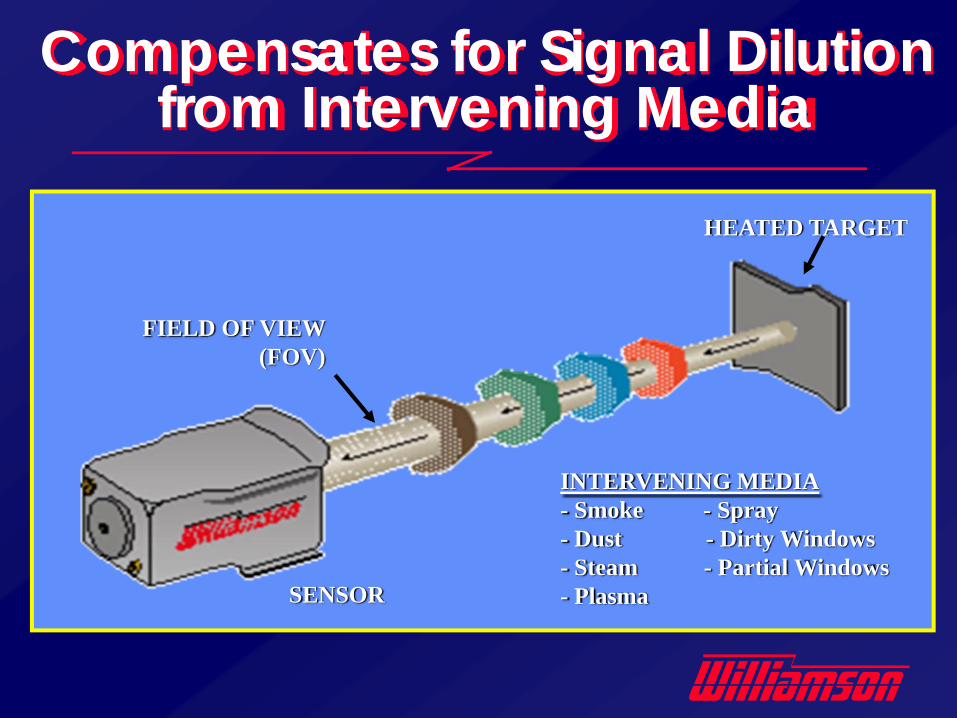
Compensates for Signal Dilution from Intervening Media
HEATED TARGET
FIELD OF VIEW (FOV)
SENSOR
INTERVENING MEDIA- Smoke - Spray- Dust - Dirty Windows- Steam - Partial Windows- Plasma
• Compensate for emissivity variation, and tend to measure the hottest temperature viewed.
• Are affected by changes in e-slope, wavelength-selective optical obstruction and excessively hot background reflections.
• Wavelength Matters!
Ratio Sensors
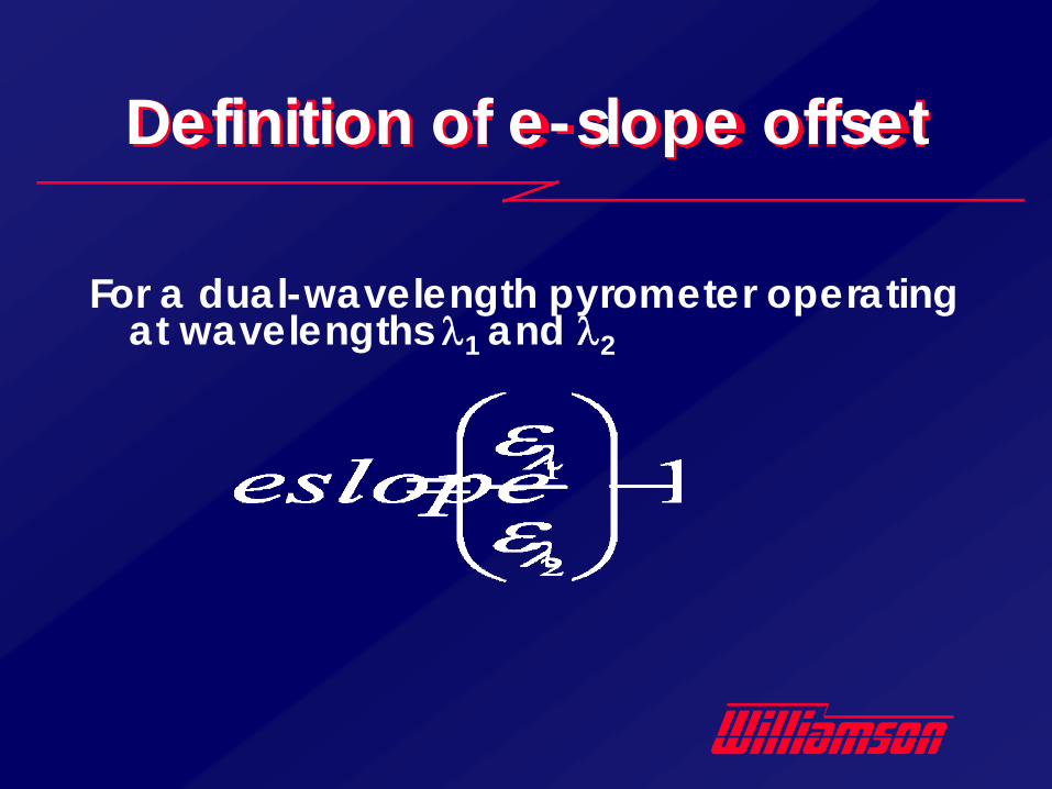
Definition of e-slope offset
For a dual-wavelength pyrometer operating at wavelengths λ1 and λ2
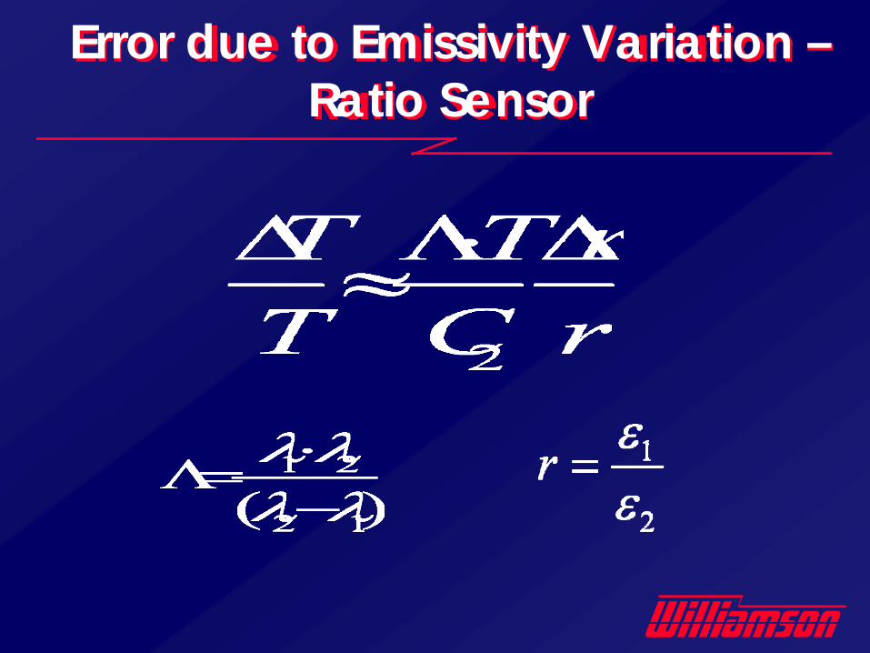
Error due to Emissivity Variation –Ratio Sensor
• Both measured wavelengths must be equally influenced by any optical obstruction or emissivity variation.
• Greater wavelength separation reduces sensitivity to e-slope variation and reduces sensitivity to warm interferences (scale / temperature gradients).
• Wavelength affects low temperature performance (available as low as 95 C/200 F).
Why Wavelength Matters
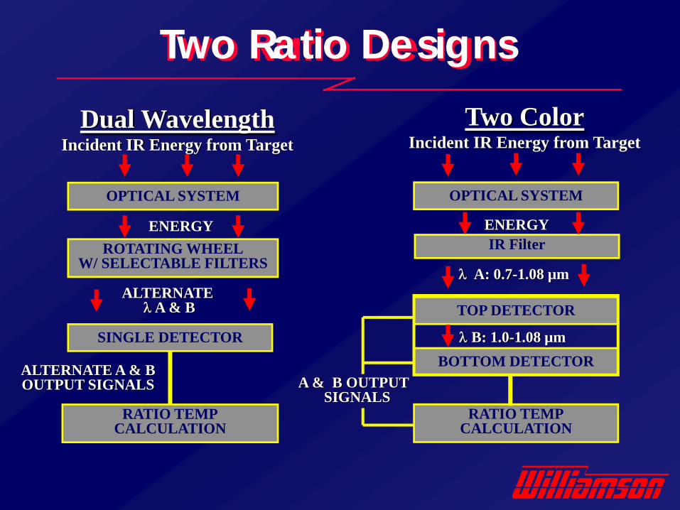
Dual WavelengthIncident IR Energy from Target
Two ColorIncident IR Energy from Target
OPTICAL SYSTEM
ENERGYROTATING WHEEL
W/ SELECTABLE FILTERS
ALTERNATEλA & B
SINGLE DETECTOR
RATIO TEMPCALCULATION
ALTERNATE A & B OUTPUT SIGNALS
OPTICAL SYSTEM
IR Filter
λ A: 0.7-1.08 µm
TOP DETECTOR
RATIO TEMPCALCULATION
A & B OUTPUT SIGNALS
BOTTOM DETECTORλ B: 1.0-1.08 µm
Two Ratio Designs
ENERGY
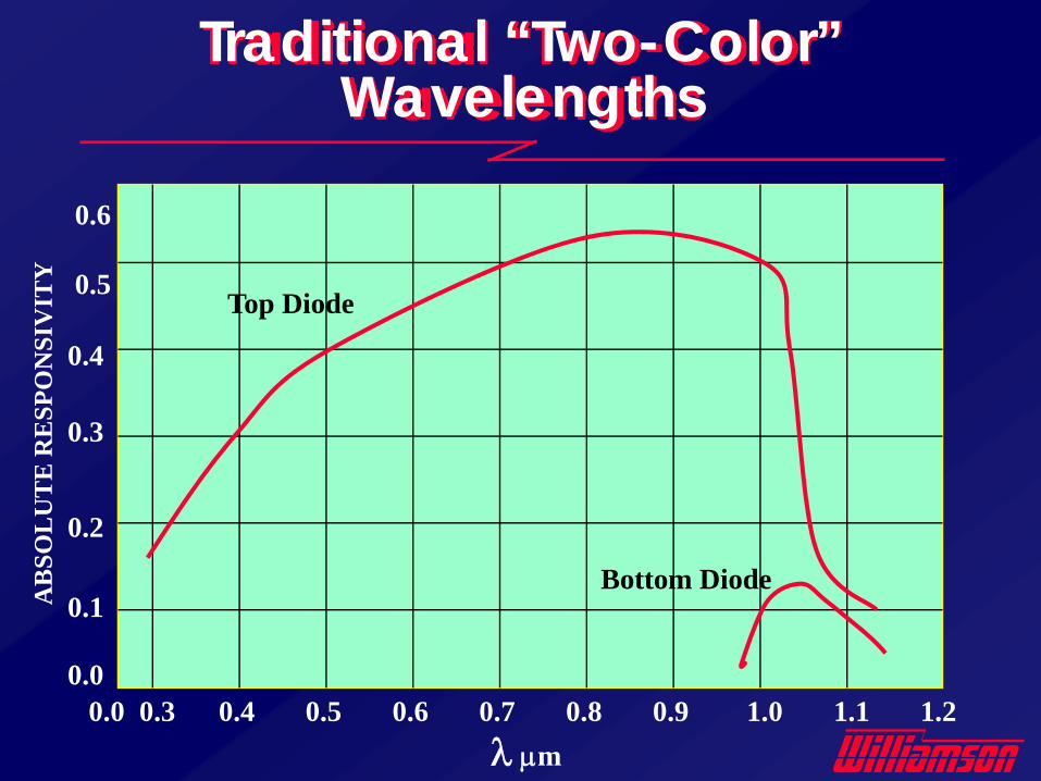
λ μm
0.6
0.5
0.4
0.3
0.2
0.1
0.00.0 0.3 0.4 0.5 0.6 0.7 0.8 0.9 1.0 1.1 1.2
Top Diode
Bottom DiodeAB
SOL
UT
E R
ESP
ON
SIV
ITY
Traditional “Two-Color” Wavelengths

Viewing Through Steam & Products of Combustion
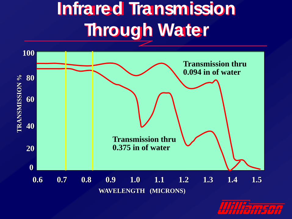
100
80
60
40
20
00.6 0.7 0.8 0.9 1.0 1.1 1.2 1.3 1.4 1.5
WAVELENGTH (MICRONS)
TR
AN
SMIS
SIO
N %
Transmission thru 0.094 in of water
Transmission thru 0.375 in of water
Infrared TransmissionThrough Water
Signal Dilution
• A measure of infrared energy compared to the amount of energy required to make a reading. 50:1 means that the sensor is collecting 50 times the energy required to make a reading.
• Typical application factors that dilute the energy signal level are– Misalignment, low emissivity, dirty optics,
water spray, dust, scale, small targets.
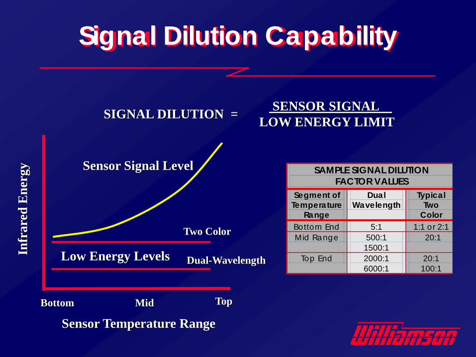
Signal Dilution Capability
Sensor Temperature Range
Infr
ared
Ene
rgy
Low Energy Levels
Two Color
Dual-Wavelength
SENSOR SIGNAL LOW ENERGY LIMITSIGNAL DILUTION =
Bottom Mid Top
SAMPLE SIGNAL DILUTION FACTOR VALUES
Segment of Temperature
Range
Dual Wavelength
Typical Two
Color Bottom End 5:1 1:1 or 2:1 Mid Range 500:1
1500:1 20:1
Top End 2000:1 6000:1
20:1 100:1
Sensor Signal Level
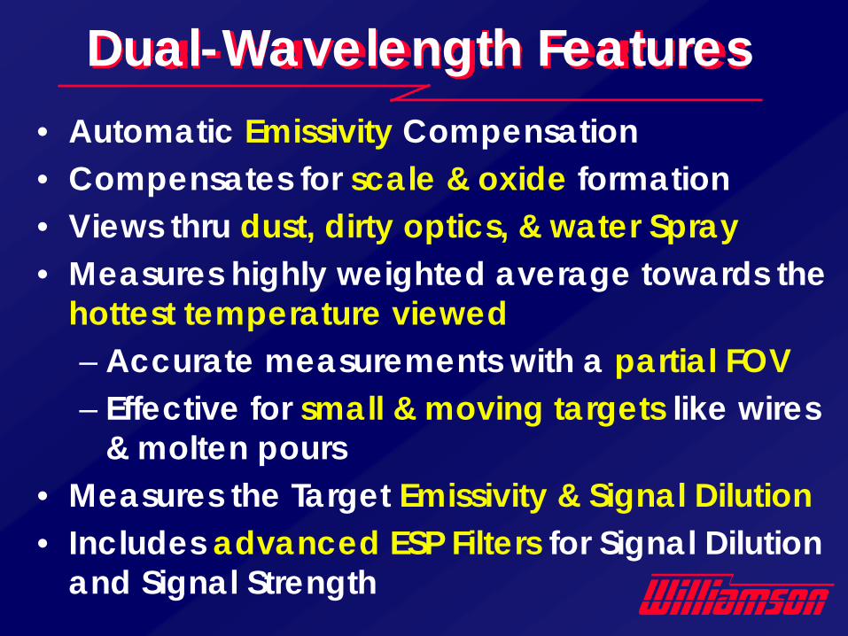
Dual-Wavelength Features• Automatic Emissivity Compensation• Compensates for scale & oxide formation• Views thru dust, dirty optics, & water Spray• Measures highly weighted average towards the
hottest temperature viewed– Accurate measurements with a partial FOV– Effective for small & moving targets like wires
& molten pours • Measures the Target Emissivity & Signal Dilution• Includes advanced ESP Filters for Signal Dilution
and Signal Strength
Ratio Sensor Summary
• Wavelength separation optimizes stability and the ability to tolerate scale & other temperature gradients.
• Ability to tolerate optical obstruction is measured by Signal Dilution.
• Selective wavelengths tolerate water, steam, flames & products of combustion.
• Difficult to measure applications in demanding industrial environments
• Applications where single wavelength sensors can not meet requirements– surfaces with low or varying emissivity– View thru obstructions or intervening media– Compensate for dirty optics, & oxide or scale
formation– Measure small or wandering targets that do
not fill the sensors field of view (FOV)
Dual Wavelength Temperature Applications
• Coke Guide• Sintered Briquette• Molten Iron Stream / Vacuum Melter• Caster Containment Zone• HSM Re-Heat Furnace Soaking Zone• Hot Mill (Scale, Water & Steam)• Weld Temperature• Heat Treat Furnaces
Sample Ratio Sensor Wavelength-Critical Applications
Multi-Variant Sensors
Multi-Variant Sensors
• Are used whenever traditional sensors are not appropriate.
• Use multiple wavelengths to characterize the emissive nature of the measurement.
• Multi-Variant algorithms are developed for each application type (usually the same from one plant to the next) to address specific emissivity or interference issues.
• Designed for difficult materials and challenging applications.
• Used where single- & dual-wavelength sensors can’t meet requirements
• Common measurements include Aluminum, Brass, Copper, Zinc, Galvanneal, Stainless Steel, Electrical Steel, High Strength Steel, Cold Rolled Steel, Magnesium, Chrome, etc… .
Multi-Wavelength Infrared Thermometers
Temperature Application Issues
FOV TargetArea
Full FOV
Partially Filled FOV
FOV Target Areaw/ Diameter (d)
HEATED TARGETBACKGROUNDREFLECTIONS
Working Distance (D)
HEAT SOURCE
InterveningMedia
Field of View (FOV)
SENSOR
ΔT (System) = ΔT (Emissivity) + ΔT (Transmission) + ΔT (Background) + ΔT (Instrument) + ΔT (Alignment)
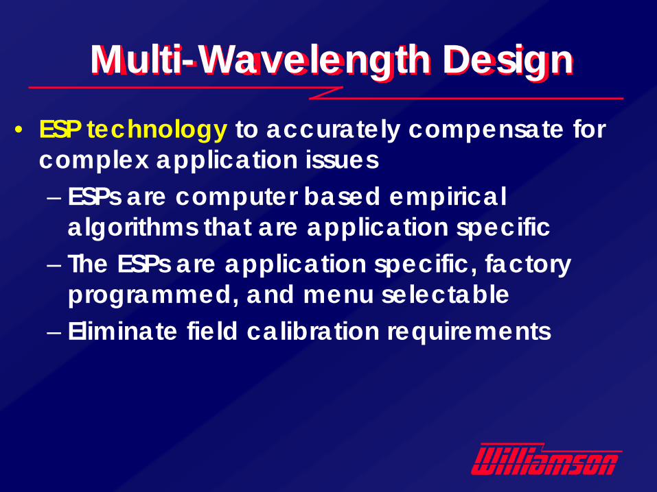
Multi-Wavelength Design• ESP technology to accurately compensate for
complex application issues– ESPs are computer based empirical
algorithms that are application specific– The ESPs are application specific, factory
programmed, and menu selectable– Eliminate field calibration requirements
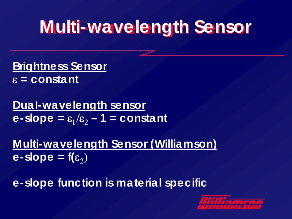
Multi-wavelength Sensor
Brightness Sensorε = constant
Dual-wavelength sensore-slope = ε1/ε2 – 1 = constant
Multi-wavelength Sensor (Williamson)e-slope = f(ε2)
e-slope function is material specific
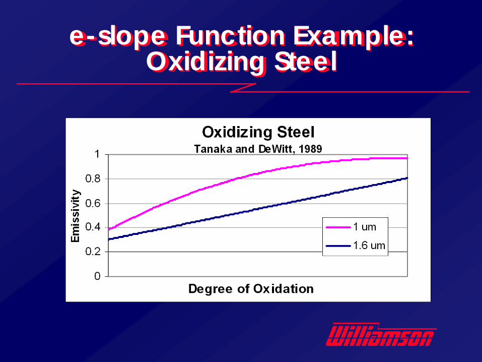
e-slope Function Example: Oxidizing Steel
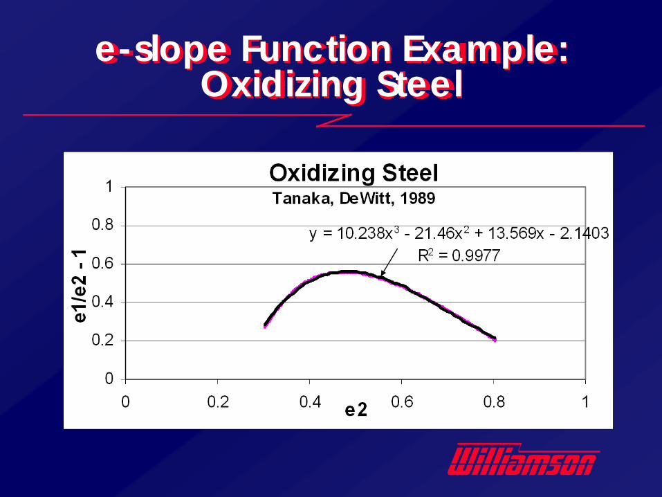
e-slope Function Example: Oxidizing Steel
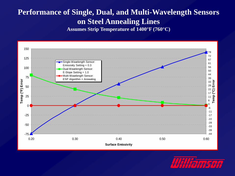
Performance of Single, Dual, and Multi-Wavelength Sensorson Steel Annealing Lines
Assumes Strip Temperature of 1400°F (760°C)
-75
-50
-25
0
25
50
75
100
125
150
0.20 0.30 0.40 0.50 0.60
Surface Emissivity
Tem
p (°F
) Err
or
-44-39-33-28-22-17-11-60611172228333944505661677278
Tem
p (°
C) E
rror
Single-Wavelength Sensor: Emissivity Setting = 0.3Dual-Wavelength Sensor: E-Slope Setting = 1.0Multi-Wavelength Sensor: ESP Algorithm = Annealing
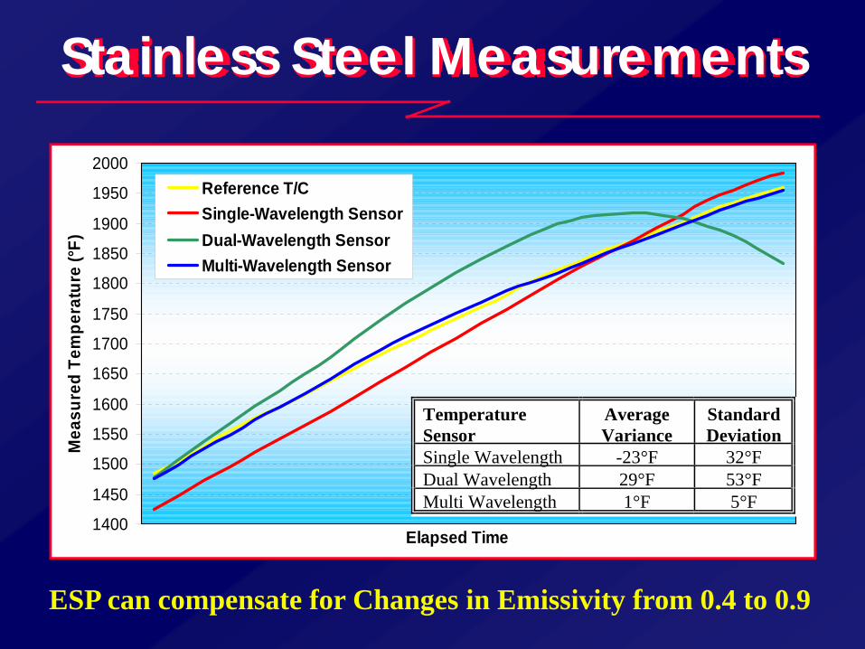
Stainless Steel Measurements
1400
1450
1500
1550
1600
1650
1700
1750
1800
1850
1900
1950
2000
Elapsed Time
Mea
sure
d Te
mpe
ratu
re (°
F)
Reference T/CSingle-Wavelength SensorDual-Wavelength SensorMulti-Wavelength Sensor
TemperatureSensor
AverageVariance
StandardDeviation
Single Wavelength -23°F 32°FDual Wavelength 29°F 53°FMulti Wavelength 1°F 5°F
ESP can compensate for Changes in Emissivity from 0.4 to 0.9
700710720730740750760770780790800810820830840850860870880890900
Tem
pera
ture
(°F)
0
0.2
0.4
0.6
0.8
1
1.2
1.4
1.6
1.8
2
Emis
sivi
ty
Reference T/C (°F)
Emissivity
Dual Wavelength (°F)
Single Wavelength (°F)
Multi Wavelength (°F)
TEST PROFILE TEST RESULTS
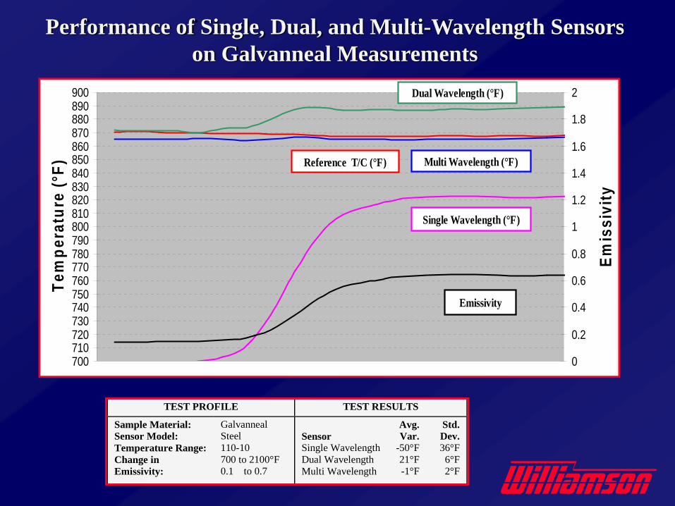
Sample Material:Sensor Model:Temperature Range:Change inEmissivity:
GalvannealSteel110-10700 to 2100°F0.1 to 0.7
SensorSingle WavelengthDual WavelengthMulti Wavelength
Avg.Var.
-50°F 21°F -1°F
Std.Dev.36°F 6°F 2°F
Performance of Single, Dual, and Multi-Wavelength Sensorson Galvanneal Measurements
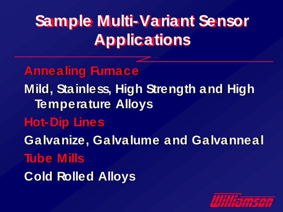
Annealing FurnaceMild, Stainless, High Strength and High
Temperature AlloysHot-Dip LinesGalvanize, Galvalume and GalvannealTube MillsCold Rolled Alloys
Sample Multi-Variant Sensor Applications
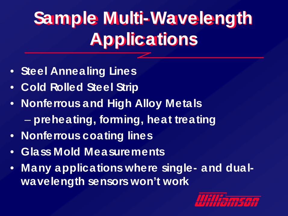
• Steel Annealing Lines• Cold Rolled Steel Strip• Nonferrous and High Alloy Metals
– preheating, forming, heat treating• Nonferrous coating lines• Glass Mold Measurements• Many applications where single- and dual-
wavelength sensors won’t work
Sample Multi-Wavelength Applications
Alignment Issues

Defining the Sensor FOVSpot Size (d) @ Working Distance (D)
d = D/F• d = Focal Diameter• D = Focal Distance• F = Optical Resolution Factor
(Formula applies to English and metric units of measurement)
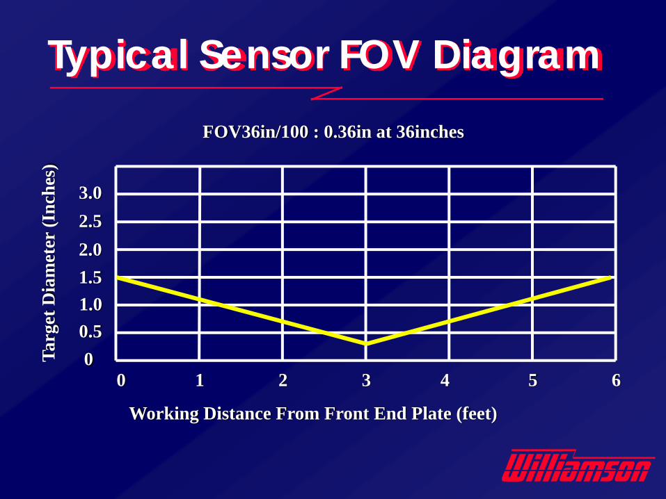
Typical Sensor FOV Diagram
00.51.01.52.02.53.0
0 1 2 3 4 5 6
Working Distance From Front End Plate (feet)
Targ
et D
iam
eter
(Inc
hes)
FOV36in/100 : 0.36in at 36inches
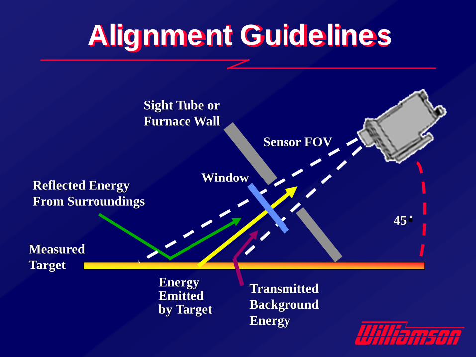
Alignment Guidelines
Measured Target
Reflected EnergyFrom Surroundings
Transmitted Background Energy
45�
Energy Emittedby Target
Sight Tube orFurnace Wall
Window
Sensor FOV
Alignment Guidelines • FOV must clear sight tubes & obstacles
• Windows must be transparent at the sensor operating wavelength
• Position & align to eliminate interference from background & reflected energy
• Rule of thumb for angle of incidence from normal : generally up to 60°, rough surfaces up to 85 °
• Provide access to tight spaces• Some operate in strong magnetic fields.• Survive hostile environments.
• Glass / Quartz• Small diameter, non-conductive mono-filament• Standard mono-coil multi-strand• Stainless Steel Braid• ArmorGuard• Rigid Light Guides
Fiber Optic Systems
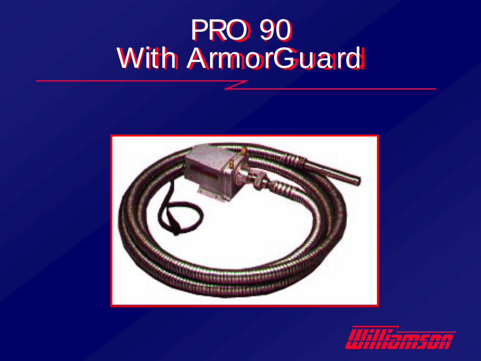
PRO 90 With ArmorGuard
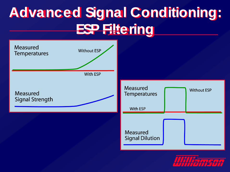
Advanced Signal Conditioning:ESP Filtering
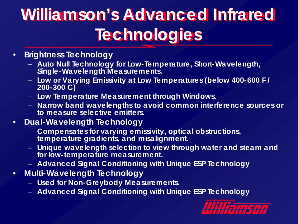
• Brightness Technology– Auto Null Technology for Low-Temperature, Short-Wavelength,
Single-Wavelength Measurements. – Low or Varying Emissivity at Low Temperatures (below 400-600 F /
200-300 C)– Low Temperature Measurement through Windows. – Narrow band wavelengths to avoid common interference sources or
to measure selective emitters.• Dual-Wavelength Technology
– Compensates for varying emissivity, optical obstructions, temperature gradients, and misalignment.
– Unique wavelength selection to view through water and steam and for low-temperature measurement.
– Advanced Signal Conditioning with Unique ESP Technology• Multi-Wavelength Technology
– Used for Non-Greybody Measurements.– Advanced Signal Conditioning with Unique ESP Technology
Williamson’s Advanced Infrared Technologies
• Line Scanners• Thermal Imaging Cameras• Flame Detectors• Hot Metal Detectors• Two-Component Background
Compensation System• Laser Reflection Multi-Variant Type
Other Infrared Technologies