infrared aviation lighting red lighting.pdf · and intensity where helipad lighting is most needed...
TRANSCRIPT

Infrared Aviation Lightingfor NVGs & Heads Up Displays
Yes, We can approve a “Standard”
Yes, We will “Innovate”
2017 USHST Infrastructure SummitWashington, D.C.

Heliport Lighting
• Relevant Reference Documents• USA, FAA
• Advisory Circular 150-5390-2• Engineering Brief - 87 • FAA Order 8900.1, Vol. 4, Ch. 9, Section 1, Fig. 4-68• Radio Technical Commission for Aeronautics, RTCA DO 275:2001 Minimum Operational
Performance Standards for Integrated Night Vison Imaging Systems Equipment• ICAO
• Annex 14 Volume II, Heliports• United Kingdom - Cap 437• Canadian Aviation Regulations (CARs) 2017-1 Standard 325.33 – Heliport
Requirements – Lights• Australian Civil Aviation Advisory Publication CAAP-92-2, & Night Helicopter
operations with Night Vison Goggles, CAAP-174- 1 (1)• Australian Military has adapted CASA MOS Part 139 - Aerodromes Section 9.4 with additional
IR requirements.

Brief Introduction and Evolution of FAA Engineering Brief 87
• What aforementioned advisory circulars have in common is the established visual beam directionality and intensity where helipad lighting is most needed to be seen by a pilot at a distance approaching the FATO under various VMC.
• These agencies have all published the data how the light must perform to be effective for the pilot to use the visual information.
• The following slide shows a comparison of the beam angles and intensities expected to be emitted for the agencies listed .
• In addition the slide also has an overlay of typical beam patterns and intensities of some non-compliant lighting available in the market place.

FAA EB-87 is the Photometric recipe standard for heliport lighting in the USA. • Common to all the advisories is the peak
angular vertical beam pattern that is Omni-direction and closely held to ground level horizon reference at maximum intensity.
• Vertical light is minimized from +16° to +90°, so that once a pilot is over the TLOF, the glare is reduced to a minimum. • The most common sign of non-
conforming lights are easily visible, that vertical light has higher intensity than side emitted light.
• How does this help for non-visible applications?• Understanding the principal of the visible
light patterns, we need to apply this concept to Infrared light in the same manner, so that visual disparity in minimized.

Comparison of FAA EB-87 compliant light on left to Non-Compliant light on the right
Performance Per FAA EB 87, Vertical and azimuth properly aligned, 36 cd on approach at 8° above horizon to less than 10 cd looking down (0°) from directly overhead.
Non-Conforming Vertical Aimed source, Vertical intensity falls off rapidly as elevation changes from directly looking down (0°) ~32 cd, to looking from the side on approach at 8°angle between 2-4 cd.

Situational Awareness• How do these visual aids help us?
• All have definite design criteria from multiple authorities from around the globe, for safe operations.
• These purpose built lights are specified and backed by years of studies and experience in the aviation industry
• Yet among the multitude of products available that do meet aviation photometric guide lines, there are some that don’t.
• How can these deficient products be identified by using just our eyes?
And exactly where did you want me to land….?

How to Improve Safety with NVG• Ample technology exists today to provide True NVG compatible both
inside and outside the cockpit.
• By True we mean not only the fact that IR sources are part of the system but that these following guidelines are met:Improved Visual Disparity for enhanced situational awareness
An image in googles must have corresponding relationship to the distance to the source. The Cosine law of intensity applies also to IR wavelengths. An overly bright source might give a false impression of nearness to an obstruction, when it could be much further away.
The proper beam shape and equivalent intensity with respect to the established visual aids so no confusion can exist in critical operations, between visual aids and NVG visualization.
The Australian Military has specified such an application for IR Obstruction Lights.

H&P Current production of a IR Beacon for the Australian Military• Obstacle lights should comply with CASA Manual of Standards (MOS)
Part 139-Aerodromes Section 9.4.
• The characteristics of the infrared sources provided on the data sheets were:• Typical Intensity 300 mW/sr
• Wavelength Infrared 850 nm
• Horizontal radiation 360 degrees
• Vertical radiation pattern:• – 15∘ to +30 ∘
• Monitoring is critical to detect failure
• Sensitivity of NVG – Relationship?
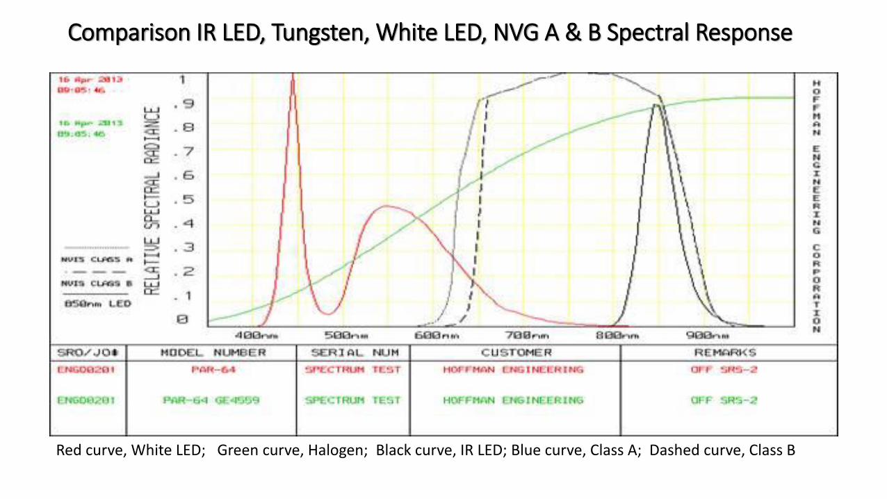
Comparison IR LED, Tungsten, White LED, NVG A & B Spectral Response
Red curve, White LED; Green curve, Halogen; Black curve, IR LED; Blue curve, Class A; Dashed curve, Class B

The Visible & Non-Visible Spectrum
Short Infrared Long Wave Infrared
310°K, 98.6°F~9.34 µm
306°K, 91.4°F,~9.47 µm
304°K, 87.7°F,~9.53 µm
308°K 95°F~9.4 µm
Infrared spans wavelengths from 700 nm to 1,000,000 nm, All objects emit light, hotter shorter wavelengths & cooler longer
1,335°K, 1,943°F~2.17 µmm
1,270°K, 1,826°F~2.28 µm
1,160°K, 1,628°F~2.50 µm
1,020°K, 1,376°F~2.84 um
770°K, 926°F~3.76 µm

Enhanced Flight Vision Systems, Short Wave Infrared Camera
0.9 mm to 1.7 mm, Indium Gallium Arsenide (InGaAs) sensors.Images reprinted from http://www.sensorsinc.com, Sensors Unlimited, UTC Aerospace Systems
Visible Naked Eye, Low Light, & Atmospheric Contaminants, Fog, Smoke
Viewed through Short Wave Infrared Camera

What is Needed in the FAA Market
• One Sizes Fits All (Nope, All Independent) Aircraft & Sensors• Waiflike comparisons (Goggles versus heads-up)• Established Priorities• First Priority Establish path for certification of visible light products for Helipad Lighting
• EP-87 is 98% Completed-Need to identify test protocols & publish in advisory circular to get product certified
• Second Priority establish new baseline protocols for non-visual aids• Critical Path: Precise spectral requirements for the two major applications; Goggles & Heads-up• Goggle wavelengths 665 nm to a 1000 nm
• Must include directionality and beam performance with respect to wavelength to insure visual disparity as compared to visual lighting products.
• Wavelength from 3,000 nm to 10,500 nm or longer for use with other IR sensor technology and heads-up display• Must also include directionality and beam performance with respect to wavelength to insure visual
disparity as compared to visual lighting products

Questions & Presenter
•Hughey & Phillips LLC •http://www.hugheyandphillips.com
•Urbana, Ohio, US
• Jerry Ehlers, Presenter•Director of Sales
• [email protected]•+1 (937) 508-8023

Headquarter – Urbana, Ohio US