infrared
TRANSCRIPT

UNIVERSITY OF QUEENSLANDDEPARTMENT OF ELECTRICAL AND
COMPUTER ENGINEERINGUNDERGRADUATE THESIS
By:
Davin Briner
Supervisor:
Dr. M. Majewski
Submission Date:
16 October 1998


16 October 1998
Davin Briner51 Kildare StreetCarina Heights QLD 4152Tel. (07) 3398 2772October 16, 1998
The DeanSchool of EngineeringUniversity of QueenslandSt Lucia, Queensland, 4072
Dear Sir,
In accordance with the requirements of the degree of Bachelor of Engineering
(Honours) in the division of Electrical and Electronic Engineering, I present the
following thesis entitled “Infrared Alarm Security System”. This work was performed
under the supervision of Dr M. Majewski.
I declare that the work submitted in this thesis is my own, except as acknowledged in
the text and footnotes, and has not been previously submitted for a degree at the
University of Queensland or any other institution.
Yours sincerely
Davin Briner

i
ACKNOWLEDGEMENTS
The author wishes to sincerely thank his project supervisor, Dr. M. Majewski, and the
Microwave and Optics Laboratories Manager, Aleksandar Rakic, for their great
guidance, encouragement and assistance during the course of this thesis.
Thanks must be given to the Hawken Electronics Workshop Team for the use of their
facilities and the high quality printed circuit boards they produced. The author also
wishes to thank Mr V. Borris, Dr. Y. Ryan and his parents for the grammatical checking
of this document.

ABSTRACT
The aim of this thesis is to design and test a prototyped infrared alarm security system.
It was decided to construct an active system over its passive counterpart, because the
active system is unaffected by the Doppler effect and is thus more versatile and
effective in hotter, wetter, windier and more humid environments. The system is very
commercially attractive and only costs $191.84.
The thesis is concerned with the analysis and design of the basic elements of the optical
and electrical systems of an active alarm system and uses an optical source never used
before in such an application. The source is a Vertical Cavity Surface Emitting Laser
(VCSEL), and possesses outstanding electrical and optical properties that may ensure its
place in the future as the only choice for an active alarm source.
A battery-powered VCSEL driver that modulates a constant current at 1kHz, a detector
and Alerting Apparatus have been constructed. The alarm proved to be very efficient; it
had a noise equivalent power of 0.5473 µW and could monitor a maximum distance of
950 m with very low power consumption. An optimal optical design has also been
achieved using Gaussian theory.
The organisation of this thesis is as follows. It begins with a brief overview of existing
active alarm security systems, states the disadvantages of each and identifies a gap in
the commercial market that can be exploited. Australian Standards are discussed for
allowable radiation limits and alarm systems. The specifications of the system are then
given. There is an overview of Vertical Cavity Surface Emitting Laser (VCSEL)
operation, and a comparison is made between this and the edge-emitting laser - a source
that is used commercially today.
A method for optimal optical design is presented, followed by the electrical modules
used for this system. Finally, a critical system evaluation is completed.
ii

iii
TABLE OF CONTENTSU
ACKNOWLEDGEMENTS.................................................................................................................. i
ABSTRACT.......................................................................................................................................... ii
GLOSSARY: LIST OF SYMBOLS .................................................................................................... x
CHAPTER ONE: INTRODUCTION ................................................................................................. 1
1.1 CHAPTER OBJECTIVES........................................................................................................ 1
1.2 IMPORTANCE OF INFRARED ALARM SECURITY SYSTEM............................................ 1
1.3 OBJECTIVES OF MY SECURITY SYSTEM.......................................................................... 1
1.4 ACTIVE INFRARED: THE ONLY SOLUTION...................................................................... 2
1.5 MOTIVATION FOR DESIGN................................................................................................. 3
1.5.1 Understanding of Commercial Market and relevant Standards ...................................... 3
1.5.2 Optoelectronic Exercise.................................................................................................. 4
1.6 BREAKDOWN OF THESIS.................................................................................................... 4
1.7 CONCLUSION........................................................................................................................ 5
CHAPTER TWO: COMMERCIALLY AVAILABLE ACTIVE INFRARED ALARM SECURITY
SYSTEMS.......................................................................................................... 6
2.1 CHAPTER OBJECTIVES........................................................................................................ 6
2.2 IPID RAPID DEPLOYMENT INTRUSION DETECTION SYSTEM (RDIDS)....................... 6
2.2.1 Operational Concept ...................................................................................................... 7
2.2.2 Operational Characteristics............................................................................................ 7
2.2.3 Technical Characteristics............................................................................................... 7
2.2.4 Cost and Applications..................................................................................................... 8
2.2.5 Commentary on RDIDS ................................................................................................. 8
2.3 COMMERCIALLY AVAILABLE PULNIX PRODUCTS ....................................................... 8
2.3.1 Pulnix Photoelectric Beam Receivers and Sensors ......................................................... 8
2.3.2 Indoor and Outdoor Applications................................................................................... 8
2.3.3 Setup .............................................................................................................................. 9
2.3.4 Features and Specifications ........................................................................................... 9

2.3.5 Commentary on Pulnix Range ..................................................................................... 10
2.4 CONCLUSION...................................................................................................................... 10
CHAPTER THREE:AUSTRALIAN LASER AND INTRUDER ALARM SYSTEM
STANDARDS................................................................................................... 12
3.1 CHAPTER OBJECTIVES...................................................................................................... 12
3.2 LASER SAFETY – AS/NZS 2211.1:1997.............................................................................. 12
3.2.1 Laser Classification...................................................................................................... 12
3.2.2 Required Warning Labels............................................................................................. 13
3.2.3 Accessible Emission Limits for Class 3B Laser Products ............................................. 13
3.2.4 Maximum Permissible Exposures (MPE)..................................................................... 14
3.2.4.1 MPE at cornea for direct ocular exposure.................................................................................14
3.2.4.2 MPE of skin to laser radiation..................................................................................................15
3.3 INTRUDER ALARM SYSTEM REQUIREMENTS .............................................................. 15
3.3.1 Requirements for Beam Interruption Detectors – AS 2201.3-1991 .............................. 15
3.3.2 Classification of Systems: AS 2201.4 – 1990 ................................................................ 16
3.3.3 Monitoring of System: AS 2201.5-1992 ........................................................................ 17
3.3.3.1 Transmission Characteristics and Requirements .......................................................................17
3.3.3.2 Performance of System ...........................................................................................................18
3.4 CONCLUSION...................................................................................................................... 18
CHAPTER FOUR: SYSTEM SPECIFICATION............................................................................. 19
4.1 CHAPTER OBJECTIVES...................................................................................................... 19
4.2 SPECIFICATIONS BASED ON THE DISADVANTAGES OF COMMERCIAL ACTIVE
INFRARED SECURITY SYSTEMS...................................................................................... 19
4.3 SPECIFICATIONS BASED ON IMPORTANT ISSUES OF RELEVANT AUSTRALIAN
STANDARDS ....................................................................................................................... 20
4.4 SPECIFICATIONS BASED ON CHAPTER ONE OBJECTIVES.......................................... 21
4.5 SUMMARY OF SYSTEM COMPONENTS TO MEET SPECIFICATIONS......................... 23
4.6 CONCLUSION...................................................................................................................... 25
CHAPTER FIVE: OPTICAL DESIGN THEORY AND OPTIMISATION METHODS................ 26
5.1 CHAPTER OBJECTIVES...................................................................................................... 26
5.2 INFRARED LIGHT AND THE ELECTROMAGNETIC SPECTRUM.................................. 26
5.3 INTRODUCTION TO VERTICAL CAVITY SURFACE EMITTING LASERS ................... 28
iv

5.3.1 Solid State Lasers .............................................................................................................. 28
5.3.2 Shortcomings of the edge emitting laser ............................................................................ 31
5.3.3 VCSELs: Overcoming the shortcomings ........................................................................... 32
5.3.4 Comparison between VCSELs and Edge Emitting Lasers ................................................. 34
5.4 OPTICAL OPTIMISATION .................................................................................................. 35
5.4.1 Goal One: Beam Collimation ............................................................................................ 35
5.4.2 Goal Two: Optimising system’s performance .................................................................... 36
5.4.3 ABCD Matrix Method: Achieving the goals ...................................................................... 37
5.5 ATTENUATORS................................................................................................................... 40
5.6 THEORETICAL POWER NEEDED TO EXTEND BEAM LENGTH.................................... 41
5.7 CONCLUSION...................................................................................................................... 43
CHAPTER SIX: ELECTRICAL DESIGN ....................................................................................... 44
6.1 CHAPTER OBJECTIVES...................................................................................................... 44
6.2 IMPORTANCE OF CIRCUIT SIMULATION ....................................................................... 44
6.2.1 PSPICE............................................................................................................................. 44
6.2.2 LogicWorks ....................................................................................................................... 45
6.3 VCSEL DRIVER ................................................................................................................... 45
6.3.1 Timer Chip ........................................................................................................................ 46
6.3.2 Constant Current Source................................................................................................... 47
6.4 RECEIVER CIRCUIT ........................................................................................................... 48
6.4.1 Silicon IR Light-to-Voltage Sensor.................................................................................... 49
6.4.2 Precision Full-Wave Rectifier ........................................................................................... 49
6.4.3 Inverter with Schmitt Trigger Input .................................................................................. 51
6.5 BATTERY POWER SUPPLY FOR VCSEL DRIVER AND RECEIVER .............................. 52
6.6 ALERTING APPARATUS .................................................................................................... 52
6.7 CONCLUSION...................................................................................................................... 53
CHAPTER SEVEN: RESULTS AND DISCUSSION....................................................................... 54
7.1 CHAPTER OBJECTIVES...................................................................................................... 54
7.2 VCSEL PERFORMANCE ..................................................................................................... 54
7.2.1 Far Field Distribution and associated full angle beam divergence .................................... 54
7.2.2 DC Electrical and Optical Characteristics ......................................................................... 56
7.2.3 Spectrum Analysis ............................................................................................................. 57
7.3 SYSTEM AND RECEIVER PERFORMANCE...................................................................... 59
7.3.1 Noise Equivalent Power: Determining the Limts............................................................... 59
v

7.3.2 Responsivity of Detector .................................................................................................... 61
7.3.3 Width of Monitoring Beam................................................................................................ 62
7.3.4 Response Time .................................................................................................................. 62
7.3.5 Safety Criteria ................................................................................................................... 62
7.3.6 System’s Durability ........................................................................................................... 63
7.3.7 System’s Costing ............................................................................................................... 63
7.4 CONCLUSION...................................................................................................................... 63
CHAPTER EIGHT: CONCLUSION................................................................................................ 65
8.1 SUMMARY........................................................................................................................... 65
8.2 FUTURE WORK................................................................................................................... 67
REFERENCES................................................................................................................................... 69
APPENDIX ONE: SYSTEM COSTING.................................................................................................72
A1.1 VCSEL DRIVER ...................................................................................................................... 72
A1.2 RECEIVER................................................................................................................................ 72
A1.3 ALERTING APPARATUS ............................................................................................................ 73
A1.4 BATTERY SUPPLY .................................................................................................................... 73
A1.5 OPTICAL COMPONENTS............................................................................................................ 73
APPENDIX TWO: SCHEMATICS .................................................................................................. 75
A2.1 VCSEL DRIVER ...................................................................................................................... 75
A2.2 RECEIVER................................................................................................................................ 76
A2.3. BATTERY POWER SUPPLY ....................................................................................................... 77
A2.4 ALERTING APPARATUS ............................................................................................................ 78
APPENDIX THREE: GAUSSIAN BEAMS...................................................................................... 79
A3.1 THE WAVE EQUATION ............................................................................................................. 79
A3.1.1 Amplitude of Field .......................................................................................................... 80
A3.1.2 Longitudinal Phase Factor ............................................................................................. 81
A3.1.3 Spot Size of Beam ........................................................................................................... 81
A3.1.4 Divergence angle ............................................................................................................ 81
A3.1.5 Higher order Gaussian modes ........................................................................................ 82
vi

A3.1.6 Q parameter.................................................................................................................... 82
A3.1.7 ABCD Law for Gaussian Beams..................................................................................... 83
APPENDIX FOUR: MATHEMATICA CODE ................................................................................ 85
APPENDIX FIVE: DATA SHEETS ................................................................................................. 86
A5.1 VCSEL DATASHEET ............................................................................................................... 86
A5.2 SILICON DETECTOR DATASHEET .............................................................................................. 87
APPENDIX SIX: PSPICE CODE ..................................................................................................... 88
A6.1 VCSEL DRIVER CODE............................................................................................................. 88
A6.2 DETECTOR CODE ..................................................................................................................... 88
APPENDIX SEVEN : RECEIVER FLOW CHART DIAGRAM .................................................... 90
APPENDIX EIGHT: ACCOMPANYING DISK.............................................................................. 91
vii

viii
LIST OF FIGURESS
FIGURE 2.1: ACTIVE INFRARED INTRUSION DETECTION SYSTEM 6
FIGURE 2.2: PULNIX INFRARED SECURITY SYSTEM 9
FIGURE 3.1: WARNING LABEL 14
FIGURE 3.2: EXPLANATORY LABEL 14
FIGURE 3.3: ALARM TRANSMISSION SYSTEM 17
FIGURE 4.1: INFRARED ALARM SECURITY SYSTEM SETUP WITHOUT ALERTING
APPARATUS 24
FIGURE 4.2: PHOTOGRAPH OF SYSTEM 24
FIGURE 5.1: CLASSICAL VIEW OF AN ELECTROMAGNETIC WAVE 27
FIGURE 5.2: THE ELECTROMAGNETIC SPECTRUM 27
FIGURE 5.3: BASIC LASER OPERATION 28
FIGURE 5.4: POPULATION INVERSION PROCESS 29
FIGURE 5.5: GAIN THRESHOLD FOR OSCILLATIONS 30
FIGURE 5.6: ELLIPTICAL BEAM SHAPE OF EDGE EMITTING LASER 31
FIGURE 5.7: PHYSICAL STRUCTURE OF VCSEL 33
FIGURE 5.8: OUTPUT BEAM OF VCSEL 34
FIGURE 5.9: APPROXIMATE RELATIONSHIP BETWEEN SOURCE AND LENS 1 35
FIGURE 5.10: INTENSITY PROFILE OF GAUSSIAN BEAM 37
FIGURE 5.11: 1D OPTICAL SYSTEM 38
FIGURE 6.1: PHOTOGRAPH OF DRIVER CIRCUIT 46
FIGURE 6.2: CURRENT OUTPUT WAVEFORM OF VCSEL DRIVER 48
FIGURE 6.3: PHOTOGRAPH OF RECEIVER CIRCUITRY 49
FIGURE 6.4: BREAKUP OF PRECISION FULL-WAVE RECTIFIER 50
FIGURE 6.5: PSPICE SIMULATION OF FULL-WAVE PRECISION RECTIFIER 50
FIGURE 6.6: TRANSFER CHARACTERISTIC DISPLAYING HYSTERISIS 51
FIGURE 6.7: DURABLE CASING OF ALERTING APPARATUS 53
FIGURE 7.1: SETUP FOR MEASURING THE FAR FIELD DISTRIBUTION 55
FIGURE 7.2: POLAR PLOT OF THE FAR FIELD DISTRIBUTION 55
FIGURE 7.3: VCSELS V-I-L-ηWP RELATIONSHIP 56
FIGURE 7.4: EXPERIMENTAL SETUP FOR SPECTRUM ANALYSIS 57
FIGURE 7.5: VCSEL’S SPECTRUM 58
FIGURE 7.6: MODE PATTERNS 58
FIGURE A3.1: ORIGIN OF THE PHASE FRONT CURVATURE 80
FIGURE A3.2: GAUSSIAN BEAM PROFILE OF A TEM0,0 MODE. 80

ix
LIST OF TABLESTABLE 2.1: TECHNICAL CHARACTERISTICS OF THE RDIDS SYSTEM 7
TABLE 2.2: SPECIFICATIONS OF VARIOUS PHOTOELECTRIC BEAM SENSORS 10
TABLE 4.1: ALARM SYSTEM COMPONENTS AND THEIR ASSOCIATED ROLES 23
TABLE 5.1: VCSEL VS EDGE EMITTING LASER 34
TABLE 5.2: KNOWN AND UNKNOWN PARAMETERS 37
TABLE 5.3 METHOD OF CALCULATING VCSEL’S ELECTRICAL POWER FOR INCREASED
BEAM LENGTH 42
TABLE 6.1: RECEIVER’S LOGIC 51
TABLE A1.1: COMPONENTS AND COSTING OF VCSEL DRIVER 72
TABLE A1.2: COMPONENTS AND COSTING OF RECEIVER 73
TABLE A1.3: COMPONENTS AND COSTING OF ALERTING APPARATUS 73
TABLE A1.4: COMPONENTS AND COSTING OF BATTERY-POWER SUPPLY 73
TABLE A1.5: COMPONENTS AND COSTING OF OPTICAL SYSTEM 74

x
GLOSSARY: LIST OF SYMBOLS
Symbol Meaning
D Duty cycle (%)d1 Distance between source and lens 1 (m)d2 Distance between lenses (m)d3 Distance between lens 2 and detector (m)E Irradiance (mW/mm2)FL Fresnel LossF Frequency (Hz)f Focal length (m)Hm Hermite polynomialH Radiant exposure (J/m2)k Wave NumberL Output Optical power (mW)MPE Maximum Permissable ExposurePelec Input electrical power (mW)R Responsivity (A/W)R(z) Radius of spherical equiphase surfacesRL Reflective LossT Transmission Matrixw0 Beam width at source (m)w1 Beam width at detector (m)τoxygen Absorption coefficient of oxygenτWV Absorption coefficient of water vapourθ Beam divergence (°)φR Radial phase factorφL Longitudinal phase factorηwp Wall plug efficiency (%)

Infrared Alarm Security System 1
CHAPTER ONE
INTRODUCTION
1.1 CHAPTER OBJECTIVES:
• Outline the importance of infrared alarm security systems
• Define the objectives of the system
• Explain why only an active system can satisfy objectives
• Discuss the motivation for designing an infrared security system
• Show the logical breakdown of this thesis.
1.2 IMPORTANCE OF INFRARED ALARM SECURITY
SYSTEM
There is enormous commercial potential in industry and business for infrared security
applications. Today we live in a dangerous world – protecting one`s family’s
business(es), possessions is of prime concern. Security systems are ubiquitous and have
become an integral part of society. The demand for security systems will increase in the
future. Improvements to these systems are inevitable as technology advances with time.
1.3 OBJECTIVES OF MY SECURITY SYSTEM
The objectives of the my security system are to:
1 Monitor the perimeter of a factory or military installation
2 Achieve a high system efficiency
3 Achieve a competitive system cost (see Appendix One)

Infrared Alarm Security System 2
4 Exceed industry’s maximum beam monitoring length of 600 metres [S2]
5 Achieve a low power consumption for a monitoring distance of at least 160
metres
6 Determine the system limits obtained when the system’s signal is equal to
the system’s noise
7 Produce a prototyped product that is durable and can withstand harsh
environmental conditions such as excessive heat, fog and humidity
8 To integrate special casing into the system to protect the receiver, detector
and their associated circuitry, from these harsh elements
9 Ensure that the monitoring beam can not be seen by the naked eye; thus, the
source must generate an infrared wave
10 Alert the intruder that the alarm has activated when the beam is broken.
1.4 ACTIVE INFRARED: THE ONLY SOLUTION
Infrared alarms can be classified as either active or passive. A passive system detects
the infrared rays that are emitted from a moving object. In contrast, an active infrared
system is triggered when the beam, emitted from a source and detected at the receiver,
is broken.
Active systems are the only choice to fulfil the objectives of Section 1.3. Active
systems are much more versatile than their passive counterparts, and can be
implemented in excessive heat and humidity. The active systems are not subject to
difficulties arising from the Doppler Effect1 [S2]. This makes the active system much
more appealing to the commercial market.
1 The Doppler effect was named after Chrsitan Doppler (1803-1853) and states that the frequency at pointB will be different to that at Point A relative to the viewer. Consider when an atom in a low-pressure gasemits radiation, a sharp monochromatic line at frequency F0 is emitted in the atom’s rest frame. If theatom is moving at a relative velocity v towards or away from the viewer, the observer will see a
frequency
±=
c
vFF 10 .

Infrared Alarm Security System 3
1.5 MOTIVATION FOR DESIGN
This section deals with the reasons for undertaking the design of an infrared alarm
security system.
1.5.1 Understanding of Commercial Market and relevant Standards
One of the goals of this thesis is to understand and gain an appreciation of the
methodology used to produce a commercial product. It is intended that the prototyped
infrared security system should overcome the weaknesses of existing commercial
products.
The steps involved in the methodology used to produce a commercial product are:
1. Choose product field – in this case, Active Infrared Alarm Security Systems.
Realise the industrial potential for this field
2. Analyse commercial Active Infrared products and note drawbacks
3. Consider relevant Australian Standards
4. Define system’s specifications; ensure that the system:
a) Capitalises on the disadvantages of existing commercial products
b) Pertains to all relevant Australian Standards
5. Build a prototype of the system
6. Expand the prototype system for commercial use. It is intended that the final
product would incorporate two beams instead of one. This would overcome
the problem of small insects intercepting a beam and triggering a false alarm.
The two transmitters and receivers would be concealed so the intruder is
unaware of the monitoring region.

Infrared Alarm Security System 4
1.5.2 Optoelectronic Exercise
The construction of an infrared alarm security system is also an exercise in
Optoelectronics. It is fascinating to integrate physical and optical principles into a
useable state of the art detection apparatus.
1.6 BREAKDOWN OF THESIS
This thesis shows the logical steps involved in understanding and gaining an
appreciation of the methodology used to produce an active infrared alarm security
system prototype that overcomes the drawbacks of commercial designs.
The breakdown of the thesis is as follows:
Chapter Two: Analyses the drawbacks of existing commercial active infrared alarm
systems
Chapter Three: Discusses the relevant Australian Standards of active infrared alarm
security systems; maximum permissable exposure levels and intruder
alarm system requirements are examined
Chapter Four : Defines the system’s specifications that:
1. Capitalise on the drawbacks of commercial products reviewed
in Chapter Two
2. Satisfy the relevant Australian Standards of Chapter Three
Chapter Five: Discusses the optical theory needed to satisfy system’s specifications
Chapter Six: Discusses the electrical design needed to satisfy system’s
specifications
Chapter Seven: Gives a critical analysis of the system; a determination is made on
whether the system’s objectives have been met
Chapter Eight: Gives a summary of the thesis and recommends future work.
Infrared Alarm Security System 5
1.7 CONCLUSION
This Chapter has outlined the importance of infrared alarm security systems. An active
system was chosen over its passive counterpart because of its versatility and its capacity
to operate in harsher environments. In comparison, the passive system is less effective
in these conditions and is affected by the Doppler Effect. The most important goal of
the prototype system is to improve on weaknesses of current existing technology.
Infrared Alarm Security System 6
CHAPTER TWO
COMMERCIALLY AVAILABLE ACTIVE
INFRARED ALARM SECURITY SYSTEMS
2.1 CHAPTER OBJECTIVES:
• Review Commercially available Pulnix and EAG Elektronik products
• Focus on the leading active infrared military system, the IPID Rapid
Deployment Intrusion Detection System (RDIDS)
• Analyse the shortcomings, cost, advantages and applications of each device
2.2 IPID RAPID DEPLOYMENT INTRUSION DETECTION
SYSTEM (RDIDS)
The American Company, Cooperative Monitoring Center (CMC) specialises in active
infrared security systems for military applications. The RDIDS utilises infrared break
beam sensor technology [T1]. The system consists of six sources and six detectors and
is shown in Figure 2.1
Figure 2.1: Active Infrared Intrusion Detection System
Infrared Alarm Security System 7
2.2.1 Operational Concept
The operational concept of the detection system is akin to all active infrared security
systems. The active infrared transmitter transmits modulated pulses of infrared energy
from the focal point of a transmitter lens to the focal point of a receiver lens. If an
intruder breaks this beam of energy, the signal strength monitored at the receiver lens is
reduced. The sensor then triggers the alarm. This system has a 100-metre long
perimeter detection zone in the shape of a vertical plane.
2.2.2 Operational Characteristics
The RDIDS has a variety of features that makes it attractive for security applications.
Features include:
• a high intruder detection accuracy − the probability of triggering a false
alarm is small
• high system durability to withstand harsh temperature, wet and foggy
conditions; this is to be expected from a military-intended security system.
• a choice between a fixed or portable security system [T1].
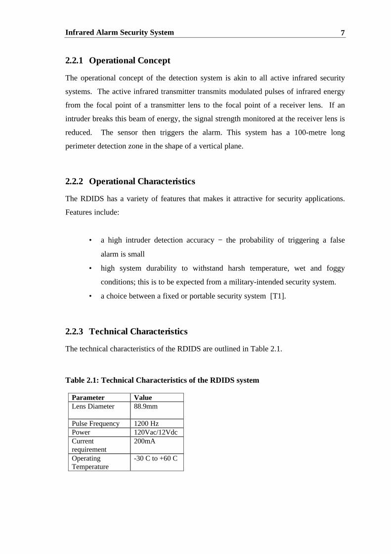
2.2.3 Technical Characteristics
The technical characteristics of the RDIDS are outlined in Table 2.1.
Table 2.1: Technical Characteristics of the RDIDS system
Parameter ValueLens Diameter 88.9mm
Pulse Frequency 1200 HzPower 120Vac/12VdcCurrentrequirement
200mA
OperatingTemperature
-30 C to +60 C

Infrared Alarm Security System 8
2.2.4 Cost and Applications
The portable sensor can be set up quickly across road and paths and around the
perimeter of a facility to detect people and vehicles. The base model of the RDIDS is
capable of covering a zone of approximately 100m. This system detects the crawling,
running or walking of intruders and costs approximately $10,000.
2.2.5 Commentary on RDIDS
The IPID Rapid Deployment Intrusion Detection System possesses all the qualities of
an excellent security system. The purpose of the RDIDS is to monitor military
institutions such as air bases and weapon factories. Because of this, the RDIDS is
designed to withstand harsh environments, has a wide operating temperature range and
can monitor a 100m perimeter zone. The only drawback of this system is its high cost
of $10 000.
2.3 COMMERCIALLY AVAILABLE PULNIX PRODUCTS
2.3.1 Pulnix Photoelectric Beam Receivers and Sensors
Pulnix caters for indoor and outdoor applications. The principle of operation is
identical to the RDIDS system and the infrared security system designed for this thesis.
2.3.2 Indoor and Outdoor Applications
Pulnix infrared security systems designed for indoor applications monitor:
• entrances and exits
• corridors
• staircases
• bank counters.
Pulnix infrared security systems designed for outdoor applications monitor building
perimeters (such as in factories or prisons), and can work efficiently in harsh

Infrared Alarm Security System 9
environments. A special hood is attached on the sensor cover to protect the system
against frost and dew.
2.3.3 Setup
Pulnix utilises twin beam technology. The beams are synchronised to work together to
reinforce the range and stability in severe weather conditions [P1].
For outdoor applications, the synchronised twin beams reduce the probability of
triggering false alarms caused by flying birds and falling leaves. Figure 2.2 shows a
graphical representation of the system.
Beam
Beam
Figure 2.2: PULNiX Infrared security System
2.3.4 Features and Specifications
The specifications of the various Pulnix products are outlined in Table 2.2. The features
that are common to all Pulnix products are as follows:
1. Rotary Optical System - the optical system of both transmitter and receiver can
be rotated a full 180 degrees to allow for side aiming
2. Insect Protection - sealed optical system prevents intrusion and interference by
insects
3. External light protection - the filter cuts out visible rays; the system has
excellent tolerance of sunlight, automobile head light, fluorescent light and
mercury light.
DetectorEmitter

Infrared Alarm Security System 10
Table 2.2: Specifications of various Photoelectric Beam Sensors
Model PR-5B PB-2OTE PB-40TE PB-60TEDetectionSystem
Breaking of 1 beam Simultaneousbreaking of 2beams
Infrared beam LEDλ=940nmModulation: 500Hz
LED pulsedbeam, Doublemodulation
Response Time 50ms or more 50msec to700msec(Variable atpot)
Supply voltage 10.5 V- 26 V (non-polarity)
12 to 30 V DC(non-polarity)
Currentconsumption
- 55mA or less 75mA orless
80mA or less
Ambienttemperaturerange
(-20 to +50) degreesCelsius
(-25 to +60)degrees Celsius
Application Indoor Indoor Outdoor OutdoorCost ($) 160.00 364.00 383.00 403.00DistanceCoverage (m)
5 40 80 120
2.3.5 Commentary on Pulnix Range
The Pulnix products are very attractive commercially. The products are relatively
cheap, minimise the probability of false alarms through an insect protection mechanism
and have external light protection. Pulnix also offers a wide range of systems to suit the
consumer market.
The drawbacks of the Pulnix products include the average efficiency that is atypical of
Light Emitting Diodes. The flimsy protective plastic coating surrounding the Pulnix
emitters and detectors also raises doubts about the durability and effectiveness of the
system operating in harsh outdoor environments.
2.4 CONCLUSION
The RDIDS and the various Pulnix systems were discussed. The main disadvantage of
the RDIDS is its cost; in comparison the Pulnix products lacked durability. It is clearly

Infrared Alarm Security System 11
evident that a niche exists in the commercial market for an active infrared alarm system
that is cheap and durable.

Infrared Alarm Security System 12
CHAPTER THREE
AUSTRALIAN LASER AND INTRUDER
ALARM SYSTEM STANDARDS
3.1 CHAPTER OBJECTIVES:
• Discuss Laser Safety pertaining to active infrared alarm security systems;
focus on issues such as manufacturing requirements, labelling, accessible
emission limits and maximum permissible exposure (MPE) at the cornea for
direct ocular exposure to laser radiation.
• Specify intruder alarm system requirements such as system classification,
requirements for beam interrupted detectors and an overview of monitoring
procedures.
3.2 LASER SAFETY – AS/NZS 2211.1:1997
Laser safety requirements are specified by the Australian Standard 2211.1:1997. The
source of the infrared alarm security system is a Vertical Cavity Surface Emitting Laser
(VCSEL). This section discusses the regulations that pertain to their use.
3.2.1 Laser Classification
Laser and laser product manufacturers must certify and label lasers [A5]. The lasers are
classified into four classes – Class 1, Class 2, Class 3A and 3B and Class 4.
The class boundaries are defined by:

Infrared Alarm Security System 13
1. The laser’s optical output power
2. The wavelength of the laser
3. The potential hazard of the laser to the human eye and skin.
The higher the Class, the more potentially dangerous the laser is. There are four classes
- Class 1, Class 2, Class 3A and 3B and Class 4. The VCSEL is a Class 3B laser. All
Class 3 lasers that emit invisible radiation are classified as Class 3B [A5]. VCSELs
operate at 850 nm (i.e. within the infrared range) and satisfy this condition.
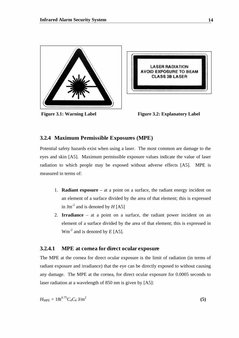
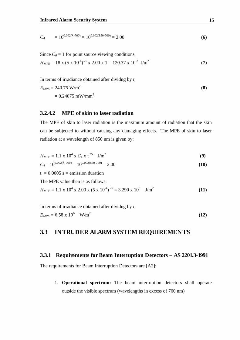
3.2.2 Required Warning Labels
Clause 5.5 of AS/NZS 2211.1:1997 states that each class 3B laser product shall have
affixed a warning label and an explanatory label shown in Figure 3.1 and 3.2
respectively [A5].
3.2.3 Accessible Emission Limits for Class 3B Laser Products
The Accessible Emission Limit is defined as the safe maximum optical output power of
a laser. This limit is determined by the emission duration of the laser’s radiation.
The accessible emission limits for the VCSEL for an emission duration of t = 0.0005
seconds is given by [A5]:
EMPE = 0.03C4 J (1)
C4 = 100.002(λ-700) = 100.002(850-700) = 2.00 (2)
Substituting numbers into equation (2),
EMPE = 0.03*2.00 = 0.06 J (3)
In terms of power obtained after dividing by t,
PMPE = 120 W (4)
Infrared Alarm Security System 14
Figure 3.1: Warning Label Figure 3.2: Explanatory Label
3.2.4 Maximum Permissible Exposures (MPE)
Potential safety hazards exist when using a laser. The most common are damage to the
eyes and skin [A5]. Maximum permissible exposure values indicate the value of laser
radiation to which people may be exposed without adverse effects [A5]. MPE is
measured in terms of:
1. Radiant exposure – at a point on a surface, the radiant energy incident on
an element of a surface divided by the area of that element; this is expressed
in Jm-2 and is denoted by H [A5]
2. Irradiance – at a point on a surface, the radiant power incident on an
element of a surface divided by the area of that element; this is expressed in
Wm-2 and is denoted by E [A5].
3.2.4.1 MPE at cornea for direct ocular exposure
The MPE at the cornea for direct ocular exposure is the limit of radiation (in terms of
radiant exposure and irradiance) that the eye can be directly exposed to without causing
any damage. The MPE at the cornea, for direct ocular exposure for 0.0005 seconds to
laser radiation at a wavelength of 850 nm is given by [A5]:
HMPE = 18t0.75C4C6 J/m2 (5)
Infrared Alarm Security System 15
C4 = 100.002(λ-700) = 100.002(850-700) = 2.00 (6)
Since C6 = 1 for point source viewing conditions,
HMPE = 18 x (5 x 10-4).75 x 2.00 x 1 = 120.37 x 10⁻³ J/m2 (7)
In terms of irradiance obtained after dividng by t,
EMPE = 240.75 W/m2 (8)
= 0.24075 mW/mm2
3.2.4.2 MPE of skin to laser radiation
The MPE of skin to laser radiation is the maximum amount of radiation that the skin
can be subjected to without causing any damaging effects. The MPE of skin to laser
radiation at a wavelength of 850 nm is given by:
HMPE = 1.1 x 10⁴ x C4 x t.25 J/m2 (9)
C4 = 100.002(λ-700) = 100.002(850-700) = 2.00 (10)
t = 0.0005 s = emission duration
The MPE value then is as follows:
HMPE = 1.1 x 104 x 2.00 x (5 x 10-4) 25 = 3.290 x 10³ J/m2 (11)
In terms of irradiance obtained after dividng by t,
EMPE = 6.58 x 10⁶ W/m2 (12)
3.3 INTRUDER ALARM SYSTEM REQUIREMENTS
3.3.1 Requirements for Beam Interruption Detectors – AS 2201.3-1991
The requirements for Beam Interruption Detectors are [A2]:
1. Operational spectrum: The beam interruption detectors shall operate
outside the visible spectrum (wavelengths in excess of 760 nm)

Infrared Alarm Security System 16
2. Maximum range: The manufacturer shall state the maximum range of the
detector as the greatest separation between the transmitter and the receiver at
which an alarm condition is not initiated as a result of a 3dB reduction in the
power level of the signal received
3. Modulation: The detector shall incorporate some method of modulation so
that the introduction of an unmodulated source of wavelength comparable
with that of the transmitter shall neither:
a) prevent an alarm condition being initiated; nor
b) initiate an alarm condition
4. Sensitivity: The detector shall initiate an alarm condition as a result of the
complete interruption of the signal received for any period longer than 40ms;
the detector shall not initiate an alarm condition as a result of the complete
interruption of the signal for any period shorter than 20ms.
3.3.2 Classification of Systems: AS 2201.4 – 1990
This standard classifies the degree to which wire-free systems are monitored, from
Class One to Class Five. Although no monitoring system will be implemented for this
thesis, this standard is of great importance; it must be followed if the product is to be
developed for the commercial market.
The graduation for these classes is determined by [A4]:
• Transmission type of the signal
• The degree to which a system distinguishes between an alarm and a fault
signal
• The method of coding to minimise the possibility of interference occcuring
between systems
The degree of complexity increases with Classes.

Infrared Alarm Security System 17
The commercial product would be best suited to Class One. The advantage of this
would be a cheaper system that would be more attractive to the consumer. In no
instance is the safety of a Class One wire-free system jeopardised. This is because
Class One requirements are very stringent. ‘The Class 1 system provides the following:
1. Transmission of a signal when a detector has gone into an alarm
condition
2. A means to distinguish between an alarm and a fault signal
3. A method of coding to give a minimum of 16 different system
identifications’ [A3].
3.3.3 Monitoring of System: AS 2201.5-1992
This Australian Standard discusses the communication that occurs between the
supervised premises and the monitoring station. Transmission Requirements and
Performance are discussed in this section.
3.3.3.1 Transmission Characteristics and Requirements
If the security system were to be upgraded for commercial purposes, it would have a
continuous and periodic transmission between the supervised premises and the central
station. Figure 3.3 illustrates how the supervised premises would be networked to the
central station.
SUPERVISED PREMISES CENTRAL STATION
Alarm Alarm Alarm Annunciation System Transmission Equipment Equipment
Alarm system interface Terminal Interface
Figure 3.3: Alarm Transmission System

Infrared Alarm Security System 18
3.3.3.2 Performance of System
It is required that the transmission system shall communicate information about the
state of the alarm system to the designated central station. The transmission system
response delay is defined as the time taken for a signal to be sent from the supervised
premises to the monitoring station. This time delay is 240 seconds for a Class 1 system.
3.4 CONCLUSION
In this chapter, four standards were reviewed:
1. AS/NZS 2211.1:1997 dealt with laser safety requirements. This standard
specified the compulsory use of warning labels and gave MPE values at the
cornea and to skin of 0.24075 mW/mm2 and 6.58 MW/m2 respectively.
2. AS2201.3 –1991 gave the requirements for Beam Interruption Detectors in
terms of operational spectrum, maximum range, modulation and sensitivity. The
prototyped system must initiate an alarm condition as a result of the beam
breaking for any period longer than 40ms.
3. AS 2201.4 –1990 gave classifications for active alarm systems. A class one
system was given for the commercial expansion of the designed prototype
system.
4. AS2201.5 –1992 discussed the conditions for an alarm transmission system that
would be implemented in the final product. The time delay between the
supervised premises and the monitoring station is 240 seconds.

Infrared Alarm Security System 19
CHAPTER FOUR
SYSTEM SPECIFICATION
4.1 CHAPTER OBJECTIVES:
• To clearly define the system’s specifications based on:
1. The disadvantages of commercial active infrared security systems
2. The relevant Australian Standards for Laser Emission and Security
Systems
3. Objectives of the prototyped security system outlined in Chapter
One.
4.2 SPECIFICATIONS BASED ON THE DISADVANTAGES
OF COMMERCIAL ACTIVE INFRARED SECURITY
SYSTEMS
The downfalls of commercial active infrared security systems analysed in Chapter Two
are given below:
• The IPID Rapid Deployment Intrusion Detection System’s high cost of
$10,000
• The Pulnix’s average efficiency atypical of Light Emitting Diodes
• The Pulnix’s lack of durability and effectiveness operating in harsh outdoor
environments due to its flimsy plastic emitter and detector casing

Infrared Alarm Security System 20
To counter these downfalls, the active security system prototype should be cost-
effective and have durable casing surrounding its modules. The system should also
implement the most effective and power-efficient laser source. This laser source is a
Vertical Cavity Surface Emitting Laser that possesses a respectable optimal wall-plug
efficiency of 11.4%.
4.3 SPECIFICATIONS BASED ON IMPORTANT ISSUES OF
RELEVANT AUSTRALIAN STANDARDS
The system must satisfy both laser safety and intruder alarm system requirements. The
maximum permissible exposure to the skin and at the cornea for direct ocular exposure
must be satisfied for the system to be considered safe. Therefore, the laser source must
possess a low input electrical power and low output optical power. The VCSEL
possesses a low threshold voltage and current of 1.45 V and 3.65 mA and has a typical
optical output Power of 2.5 mA. This reinforces the need for a Vertical Cavity Surface
Emitting Laser as the system’s source.
A highly sensitive receiver is required to detect the low optical output power of the
VCSEL. The TSL261 is an excellent detector that has an in-built amplifier and filter to
harness out any unwanted signals. The TSL261 will be discussed further in Chapter
Six.
Next, one must consider the requirements for beam interruption detectors, specified by
Australian Standard AS 2201.3-1991. According to this standard, the detector must
prevent an alarm condition being initiated by a signal other than the modulation signal.
This indicates that two system specifications are needed:
1. The VCSEL must be driven at a modulated frequency; 1kHz was arbitrarily
chosen.
2. The detector must have an in-built filter in its internal setup.

Infrared Alarm Security System 21
The TSL261 satisfies this latter condition, and reinforces this excellent choice of
detectors.
Another issue relevant to AS 2201.3-1991 is the system’s sensitivity. The system must
only initiate an alarm condition as a result of the complete interruption of the signal
received for any period longer than 40ms. Hence, one must carefully examine the
sensitivity of the detector to ensure that it is not over sensitive. The TSL261 will be
tested thoroughly to ensure that this alerting condition is satisfied.
4.4 SPECIFICATIONS BASED ON CHAPTER ONE
OBJECTIVES
This section outlines the objectives of Chapter One and the methods, and electrical
and/or optical equipment needed to achieve these objectives. Further information
regarding optical theory and electrical components can be found in Chapters Five and
Six respectively.
Objective 1: Monitor the perimeter of a factory or military Institution.
Proposed Solution 1: Mirrors should be utilised to minimise the number of sources
and detectors used. Two lenses should be used to collimate the
beam and then focus the beam on the detector.
Objective 2: Achieve a high system efficiency.
Proposed Solution 2: A very efficient source should be used. A VCSEL is ideal for
this. A highly sensitive detector should also be incorporated
into the design. The TSL261 satisfies this condition.
Objective 3: Achieve a competitive system cost.
Proposed Solution 3: Electrical and Optical components must be chosen that achieve
the task at hand. Cost must not be sacrificed for durability and
system’s effectiveness.

Infrared Alarm Security System 22
Objective 4: Exceed industry’s maximum beam monitoring length of 600
metres.
Proposed Solution 4 The source’s beam divergence should be as small as possible.
The VCSEL satisfies this condition. A good choice of lenses to
collimate the beam effectively at the laser and to focus it on the
detector is also required.
Objective 5: Achieve a low power consumption for a monitoring distance of
at least 160 metres.
Proposed Solution 5: Simulate 160 metres with the use of attenuators.
Objective 6: Produce a prototyped product that is durable and can withstand
harsh environmental conditions such as excessive heat,
humidity and cyclonic conditions.
Proposed Solution 6: Design Special casing to protect the receiver, detector and their
associated circuitry. Choose components that can function to
their full capacity under excessive temperature changes.
Objective 7: Ensure that the monitoring beam can not be seen by the naked
eye.
Proposed Solution 7: The VCSEL must emit infrared radiation. The VCSEL being
used operates at 850nm and is unseen by the naked eye. An
appropriate detector must be chosen that works efficiently at
this wavelength. Here, a Silicon detector is the best option.
Objective 8: Alert the intruder that the alarm has activated when the beam is
broken.
Proposed Solution 8: Design alerting apparatus that activates the buzzer for at least
six seconds.

Infrared Alarm Security System 23
4.5 SUMMARY OF SYSTEM COMPONENTS TO MEET
SPECIFICATIONS
The components, objectives and their associated uses are summarised in Table 4.1. The
infrared alarm security setup is shown in Figure 4.1. A photograph of the system can be
seen in Figure 4.2.
Table 4.1: Alarm System Components and their associated roles
Alarm System Component Purpose Objective Number2 Attenuators • Simulates real conditions
• Increases monitoringdistance from 1.6m to 160m.
• 5
1 Laser Driver • Modulates VCSEL at 1kHz • 1,2Vertical Cavity Surface EmittingLaser (VCSEL)
• Efficient laser (11.4% wallplug efficiency)
• Operates at wavelength of850nm
• 2,5,7
3 mirrors • Minimises number ofemitter and detector arrays
• Reflects beam 90 degrees
• 1
Lens A • Collimates beam• Increases monitoring beam’s
diameter
• 4
Lens B • Focuses beam onto Silicondetector
• 4
1 Silicon Detector • Receives beam• Silicon most efficient at
850nm.
• 2,3,4
Detector Circuitry • Filters out unwanted signals• Activates buzzer only when
beam is not received atdetector.
• 2
Alarm Buzzer • Acts as deterrent for intruder• Active when alarm triggers
• 8

Infrared Alarm Security System 24
Figure 4.1: Infrared Alarm Security System Setup without Alerting Apparatus
Figure 4.2: Photograph of System
Mirror
Lens
Detector
Attenuators
VCSEL
VCSEL
Driver
Infrared Alarm Security System 25
4.6 CONCLUSION
This chapter has clearly defined the prototype system’s specifications by considering
relevant Australian Standards and capitalising on the disadvantages of commercial
systems. Thus the new system is intended to be durable and cost-efficient. It has been
decided to use a VCSEL as the laser source because of its low divergent beam, its
invisible output spectrum, its respectable wall-plug efficiency, its low input electrical
power and its low output optical power. A highly sensitive Silicon Detector was chosen
due to its high sensitivity and its capacity to filter out unwanted signals.

Infrared Alarm Security System 26
CHAPTER FIVE
OPTICAL DESIGN THEORY AND
OPTIMISATION METHODS
5.1 CHAPTER OBJECTIVES:
• Define infrared light and the electromagnetic spectrum
• Introduce operational and physical characteristics of Vertical Cavity Surface
Emitting Lasers (VCSELs)
• Compare VCSELs to edge-emitting lasers
• Show that VCSELs are the better laser source for an active infrared security
system
• Discuss Gaussian beams, the ABCD matrix and optical principles of lenses
and atteunuators
• Examine optimisation design methods for the security system.
5.2 INFRARED LIGHT AND THE ELECTROMAGNETIC
SPECTRUM
Electromagnetic waves are related patterns of electric and magnetic force [F2]. The
direction of the electric and magnetic fields and the direction of the wave's motion are
perpendicular to one another. Figure 5.1 shows a classical view of an electromagnetic
wave.

Infrared Alarm Security System 27
Figure 5.1: Classical view of an Electromagnetic Wave
These waves are generated by the oscillation of electric charges and travel through free
space at the speed of light, 2.998*108 m/s [F2].
Infrared light is an invisible band in the electromagnetic spectrum. This is shown in
Figure 5.2. It is invisible to the human eye and possesses identical properties to visible
light. The light can be reflected (bounced back), collimated (directed in a straight line),
diffracted (broken up) and refracted (bent). The propagation of infrared light through
free space using traditional optical elements has been modelled using Gaussian Theory
(see Appendix Three). Thus, infrared light is ideal to use in a security system.
Figure 5.2: The Electromagnetic Spectrum

Infrared Alarm Security System 28
5.3 INTRODUCTION TO VERTICAL CAVITY SURFACE
EMITTING LASERS
The VCSEL is a solid state laser device. In contrast to the conventional edge-emitting
lasers, VCSELs present unique optical and electrical properties which make these
devices very attractive. These include a 99% device yield, low threshold voltage
(1.45V), low threshold current (3.68 mA), a respectable wall-plug efficiency2 (ηeff =
11.4%), single-longitudinal mode emission and a low-divergence circular output beam
[V1].
This section will introduce the basic concepts of the solid state laser. The shortcomings
of the edge-emitting laser will be discussed and it will be shown how VCSELs can
overcome these shortcomings. The importance of VCSELs over edge-emitting lasers
for an active infrared security system is also examined.
5.3.1 Solid State Lasers
The basic operation of a solid state laser is shown in Figure 5.3. Two mirrors are used
to form a cavity. Optical radiation is confined by the mirrors and causes the photons to
reflect back and forth inside the cavity. The light is then forced to pass through an
optical gain medium many times, each time the field being amplified [S3].
Figure 5.3: Basic Laser Operation
2 Wall-plug efficiency is a measure of the ratio of the optical output power to the supplied electricalpower.

Infrared Alarm Security System 29
Only certain wavelengths are allowed to resonate within the cavity. The resonant wave
must fit in the cavity with an integer number of half-wavelengths. Thus:
where: q is an integer
d is the cavity length
∆F is the change of frequency within the laser cavity (Hz) [D1].
From (14), the spacing of the resonant frequencies is inversely proportional to the cavity
length. That is, a small d gives widely spaced frequency modes and a large d gives
narrowly spaced frequency modes.
Optical gain within the cavity is due to the state transition between two energy bands in
the gain medium [K1]. This is shown in Figure 5.4. There is not an exact quantity in
energy difference between the two energy bands. This means that there is a range of
energies due to the finite smearing of energy levels in the crystal [C2]. Thus, different
frequencies can cause optical gain.
Figure 5.4: Population Inversion process
(13)
(14)
f
cqqd
∆==
22
λ
d
cf
2=∆∴

Infrared Alarm Security System 30
The frequencies that have the potential to resonate with the cavity mode are those where
the optical gain of the medium exceeds the losses encountered by the cavity. Therefore,
there are two basic conditions that the laser requires for oscillation:
(a) the optical gain of the material exceeds the losses in the cavity at the
frequency of interest
(b) the frequency of interest satisfies one of the cavity modes.
This is shown by Figure 5.5. The arrows show the cavity modes whilst the hatched area
is where the gain is higher than losses and laser action can occur. L is the cavity loss in
dB [C2].
Figure 5.5: Gain threshold for oscillations
Stimulated emission is a mechanism whereby the electromagnetic field couples to the
quantum-mechanical energy states in the gain medium [E1]. Figure 5.4 illustrates this
point.
The mechanism of stimulated emission is central to the gain medium providing optical
gain. This is attributed to the fact that some photons generate excited atoms in the gain
medium to undergo a decay into a lower energy state which releases a photon of exactly
the same energy as the initiating photon.

Infrared Alarm Security System 31
Atoms are raised from the ground state into some energy state E2 via the pumping
process. This effect lasts a long time. Photons create stimulated emission, exciting the
atoms to decay into an ephemeral intermediate energy level E1. Atoms from level E1 are
decayed to the ground state by a process called spontaneous emission. If E1 has a much
shorter life than E2, the atoms will be emptied at a fast enough rate to ensure that the
population of E2 exceeds that of E1. Population inversion is the name given to this
occurrence. It is the basic requirement for stimulated emission to be more dominant
than the natural absorption mechanism in the material [C2][A1].
5.3.2 Shortcomings of the edge emitting laser
There are three main shortcomings of the edge emitting laser. The first is the elliptical
beam shape of this laser. This is shown in Figure 5.6. The beam shape implies that to
obtain a good coupling to a fibre, an astigmatic lens is required which has exactly the
correct focal length. This is very hard to achieve in practice because of the wide range
of edge emitting lasers, each requiring its own astigmatic lens [C2].
Figure 5.6: Elliptical Beam Shape of Edge Emitting Laser
The second problem is the large divergence angle of the beam (60°)[S3]. This is
because the depletion layer of the pn junction (i.e. the active region) is very thin,
resulting in a very small output aperture [C2][S3]. A hetero-junction can reduce this
problem.3
3 A Hetero-Junction is a junction with a number of layers of varying doping. It increases the depletionregion width and consequently widens the aperture [C2].
Output
Beam
Output
Beam
Infrared Alarm Security System 32
The third problem concerns the long cavity length (many wavelengths long). From
equation (14), a large cavity length results in narrowly spaced longitudinal frequency
modes. This increases the likelihood of many more modes fitting into the lasing
frequency range [S3][C2]. Ideally, a short cavity length would allow only a few modes
within the lasing frequency range as these modes would be spaced widely apart.
5.3.3 VCSELs: Overcoming the shortcomings
VCSELs overcome the shortcoming of the edge emitting laser by using a micro-cavity.
A micro-cavity is a very short cavity that results in a widely spaced frequency range.
The use of the micro-cavity is two-fold: to reduce the number of the longitudinal modes
the laser may support, and to increase the coherence length of the VCSEL [C2][S1]. A
large aperture is also needed to increase the coupling efficiency. This is achieved by a
device called a Vertical Cavity Surface Emitting Laser. The VCSEL mirrors are grown
on the substrate and are not cleaved [C2]. Thus VCSELs may be constructed in arrays
and may be easily integrated with other electronics [S3][C2].
Band-gap engineering techniques such as molecular beam epitaxy and metal organic
vapour phase epitaxy are employed for the construction of the VCSEL [C2]. Both
methods allow the growth of many thin layers of semiconductor materials with atomic
precision [C2][S1]. This way, the band-gap energies of the resultant material can be
altered as desired and the desired electrical and optical properties of the material may be
specified [S3].
The structure of the VCSEL can be seen in Figure 5.7.
Infrared Alarm Security System 33
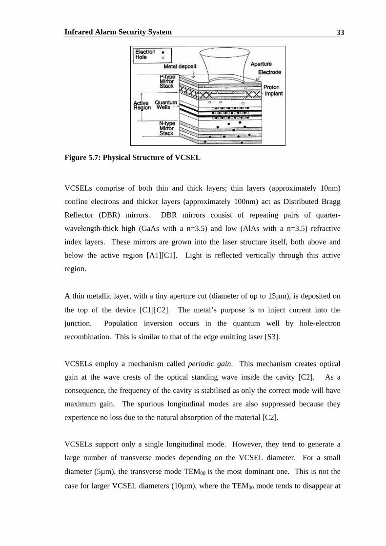
Figure 5.7: Physical Structure of VCSEL
VCSELs comprise of both thin and thick layers; thin layers (approximately 10nm)
confine electrons and thicker layers (approximately 100nm) act as Distributed Bragg
Reflector (DBR) mirrors. DBR mirrors consist of repeating pairs of quarter-
wavelength-thick high (GaAs with a n=3.5) and low (AlAs with a n=3.5) refractive
index layers. These mirrors are grown into the laser structure itself, both above and
below the active region [A1][C1]. Light is reflected vertically through this active
region.
A thin metallic layer, with a tiny aperture cut (diameter of up to 15µm), is deposited on
the top of the device [C1][C2]. The metal’s purpose is to inject current into the
junction. Population inversion occurs in the quantum well by hole-electron
recombination. This is similar to that of the edge emitting laser [S3].
VCSELs employ a mechanism called periodic gain. This mechanism creates optical
gain at the wave crests of the optical standing wave inside the cavity [C2]. As a
consequence, the frequency of the cavity is stabilised as only the correct mode will have
maximum gain. The spurious longitudinal modes are also suppressed because they
experience no loss due to the natural absorption of the material [C2].
VCSELs support only a single longitudinal mode. However, they tend to generate a
large number of transverse modes depending on the VCSEL diameter. For a small
diameter (5µm), the transverse mode TEM00 is the most dominant one. This is not the
case for larger VCSEL diameters (10µm), where the TEM00 mode tends to disappear at

Infrared Alarm Security System 34
bias currents above threshold. This is due to a process called hole burning where a
mode has depleted the gain in a specific spatial position over the gain medium, due to
its large amplitude at that particular spot [C2] .
5.3.4 Comparison between VCSELs and Edge Emitting Lasers
VCSELs are superior to edge emitting lasers as a source for an active infrared security
system. This is because VCSELs are much cheaper to manufacture than edge emitting
lasers as the VCSEL mirrors do not have to be cleaved. The VCSEL’s output beam is
also circular rather than elliptical (shown in Figure 5.8), and its divergence angle is very
small (approximately 6°) compared to that of the edge-emitting laser (approximately 60
degrees). Obviously, a less divergent, circular beam is easier to work with and to
manipulate according to the designer’s needs. Table 5.1 shows a comparison between
the VCSEL and the Edge Emitting Laser [C1].
Figure 5.8: Output beam of VCSEL
Table 5.1: VCSEL VS Edge Emitting Laser
Edge Emitting Laser VCSELs1. Very divergent beam. Harder to
manipulate beam.2. Astigmatic beam; hard to correct3. Emission parallel to surface4. Large cavity length. Supports multi-
modes. May cause chromaticaberration in imaging systems
5. More expensive to manufacture6. Same Driver Voltage (1.8V) as VCSEL
but higher Current (40-60mA). Lasernot power efficient.
1. Small divergent beam due to largeraperture. Easier to work with.
2. Symmetric Beam – easy to workwith
3. Emission perpendicular to surface4. Short cavity length. Supports only a
few longitudinal modes. Has manytransverse modes.
5. Cheaper to manufacture.6. Low Driver Voltage (1.8V) and
Current (15mA) makes for a morepower efficient laser
Infrared Alarm Security System 35
5.4 OPTICAL OPTIMISATION
This section deals with the ABCD Matrix Method employed to optimise the optical
design. Optimisation is a very broad term and must be defined exactly to ensure that the
optimisation goals are achieved.
5.4.1 Goal One: Beam Collimation
The first goal is to achieve a collimated beam to monitor the system and to determine its
maximum spot size using optical theory.
To collimate a Gaussian Beam, the divergence of the source should be as small as
possible. Thus, the maximum distance between the source and Lens 1 and the detector
and Lens 2 should equal that of the lenses’ focal length [O1][N1].
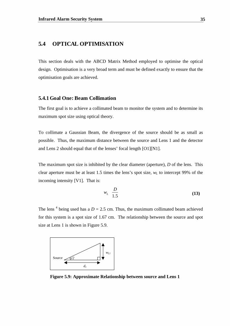
The maximum spot size is inhibited by the clear diameter (aperture), D of the lens. This
clear aperture must be at least 1.5 times the lens’s spot size, wL to intercept 99% of the
incoming intensity [V1]. That is:
The lens 4 being used has a D = 2.5 cm. Thus, the maximum collimated beam achieved
for this system is a spot size of 1.67 cm. The relationship between the source and spot
size at Lens 1 is shown in Figure 5.9.
5.1
DwL ⟨ (13)
Source
wL1
d1
θ/2
Figure 5.9: Approximate Relationship between source and Lens 1

Infrared Alarm Security System 36
The approximate distance from the source to Lens 1 (d1) is calculated using the
tangential rule. Thus:
where: θ/2 is the half-divergence angle = 7.255°
Using equation (14), d1 equals 13.1 cm. This exceeds the focal length of the lens and
thus does not satisfy the condition for a collimated beam. Hence, the largest possible
distance between the source and the lens is 10cm that results in a beam spot size of
1.27cm.
5.4.2 Goal Two: Optimising system’s performance
The second goal is to achieve an optimal system performance by focussing the beam on
to ninety per cent of the detector.
The Gaussian’s intensity beam profile is infinite, as shown in Figure 5.10. However,
most of the profile falls between the 1/e2 points. Thus, the Gaussian beam’s irradiance
profile should focus on at least 1-1/e2 = 86.47% (90% is used) of the detector.
Therefore, the beam width at the detector is 0.9 * 2mm = 1.8mm.
4 There was no choice of lenses due to the department’s tight financial situation. A better lens could havebeen chosen which would have given a large spot size at Lens 1 and thus have increased the monitoringdiameter of the beam
=∴
=
2tan
2tan
11
1
1
θ
θ
L
L
wd
d
w
(14)

Infrared Alarm Security System 37
Figure 5.10: Intensity profile of Gaussian Beam
5.4.3 ABCD Matrix Method: Achieving the goals
The ABCD Matrix Method is used to calculate the system parameters to satisfy the two
optimisation goals of 5.3.1 and 5.3.2. The known and unknown parameters of the
system can be found below in Table 5.2:
Table 5.2: Known and Unknown Parameters
Parameter Meaning of Parameter Value KnownValue?
UnknownValue?
w0 Beam width at source 6µm yesw1 Beam width at detector 0.0018m yesλ0 Laser Beam Wavelength 850nm yesd1 Distance from source to Lens 1 0.1m yesd2 Distance from Lens 1 to Lens 2 yesd3 Distance from Len 2 to detector yesf Focal Length of Lens 1 and Lens
20.1m yes
The two optimisation goals specified crucial information needed to solve the unknown
parameters of the system. Goal one, beam collimation specified the distance d1 between
the source and Lens 1 whilst goal two, optimising the system’s performance specified
the beam width at the detector.
The ABCD matrix method incorporates Gaussian Beam Theory and relates the q
parameter of one point of the optical system to the other (see Appendix Three). Using
the ABCD Matrix approach, the optical system is transformed from a two dimensional

Infrared Alarm Security System 38
(x-y-axis) to a one dimensional system (x-axis). The two dimensional system was
presented as Figure 4.1 in the previous chapter. The one dimensional optical system is
shown in Figure 5.11. The planar mirrors used have no effect on the beam’s profile.
Therefore, they are not incorporated in this analysis.
Figure 5.11: 1D Optical System
The system consists of five building blocks:
1. Block One: free space of distance d1
2. Block Two: collimating lens of focal length f1
3. Block Three: free space of distance d2
4. Block Four: converging lens of focal length f2
5. Block Five: Free space of distance d3.
A relationship exists between the VCSEL laser source and the detector based on the
following two assumptions:
1. The laser beam emitted from the source is a Gaussian Beam
2. The VCSEL transverse mode is a basic TEM00 mode and other higher order
modes are ignored.
The combined ABCD matrix known as the combined transmission matrix is:
(15)
−++−
+−
+−+−+−−
−+−−
=
−
−
=
=
f
d
f
dd
f
d
f
d
f
df
ddd
f
dd
f
ddd
f
dd
f
ddd
f
d
f
dd
f
d
f
d
ff
TTTTTDC
BABLOCKBLOCKBLOCKBLOCKBLOCK
COMBINED
22211
22
221
331
23212131
13
23223
123
12345
122
1
10
d11
101
10
d11
101
10
d1
Infrared Alarm Security System 39
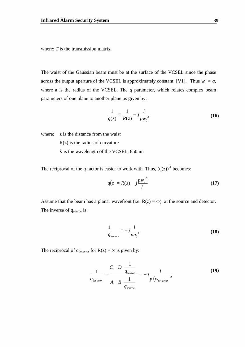
where: T is the transmission matrix.
The waist of the Gaussian beam must be at the surface of the VCSEL since the phase
across the output aperture of the VCSEL is approximately constant [V1]. Thus w0 ≈ a,
where a is the radius of the VCSEL. The q parameter, which relates complex beam
parameters of one plane to another plane ,is given by:
where: z is the distance from the waist
R(z) is the radius of curvature
λ is the wavelength of the VCSEL, 850nm
The reciprocal of the q factor is easier to work with. Thus, (q(z))-1 becomes:
Assume that the beam has a planar wavefront (i.e. R(z) = ∞) at the source and detector.
The inverse of qsource is:
The reciprocal of qdetector for R(z) = ∞ is given by:
(16)
(17)
(18)
(19)
( )λ
π 20)(
wjzRzq +=
20)(
1
)(
1
wj
zRzq πλ
−=
20
1
aj
q source πλ
−=
( )2detdet 1
1
1
ector
source
source
ector wj
qBA
qDC
q πλ
−=
+
+
=

Infrared Alarm Security System 40
The left and right hand side of (19) are separated into their real and imaginary
components and then equated. Two equations and two unknowns, d2 and d3 are
obtained. It is expected that d3 should be less than the focal length of the lens. If d3
were to equal this focal length, the beam width at the detector would only be a point.
The specified width set by optimisation goal 2 and the system’s optimal performance
would not be achieved. Consequently, the system’s performance would not be
satisfied..
A program called Mathematica is used to solve for d2 and d3. The Mathematica code
can be found in Appendix Four. The resulting parameters calculated using Mathematica
are:
d2 = 1.51m
d3 = 0.085m
These results are valid since d3 is less than the focal length of the lens and d2 is
mathematically determined by d1, f, d2, w0 and w1.
5.5 ATTENUATORS
Attenuators are used to simulate an increase in the monitoring distance of the alarm
system without physically expanding the system. The attenuators accomplishes this by
limiting the amount of light passing through the device. The direct relationship between
transmission percent and monitoring distance is:
where: MD is monitoring distance (metres)
TP is the overall transmission percent (%)
(20)
TPMD
%1005.1 ×=

Infrared Alarm Security System 41
Light transmission through the attenuator is directly proportional to the wedge distance
of the device. Transmission percentages less than 5% are obtained by placing two
attenuators in series. The overall transmission percentage is then:
where:TP1 and TP2 are the transmission percentages of attenuators one and two
respectively.
5.6 THEORETICAL POWER NEEDED TO EXTEND BEAM
LENGTH
The electrical input power of the VCSEL required to extend the system’s Beam Length
is calculated by analysing the system’s components in a backward fashion, starting from
the detector and progressing through to the source [W2]. The steps undertaken are
outlined below in Table 5.3. The absorption of oxygen and water vapour are also
included for a monitoring distance of 600m [H2]. This ensures that the calculation is
accurate for conditions in harsh wet environments.
(21)21 TPTPTP ×=
Infrared Alarm Security System 42
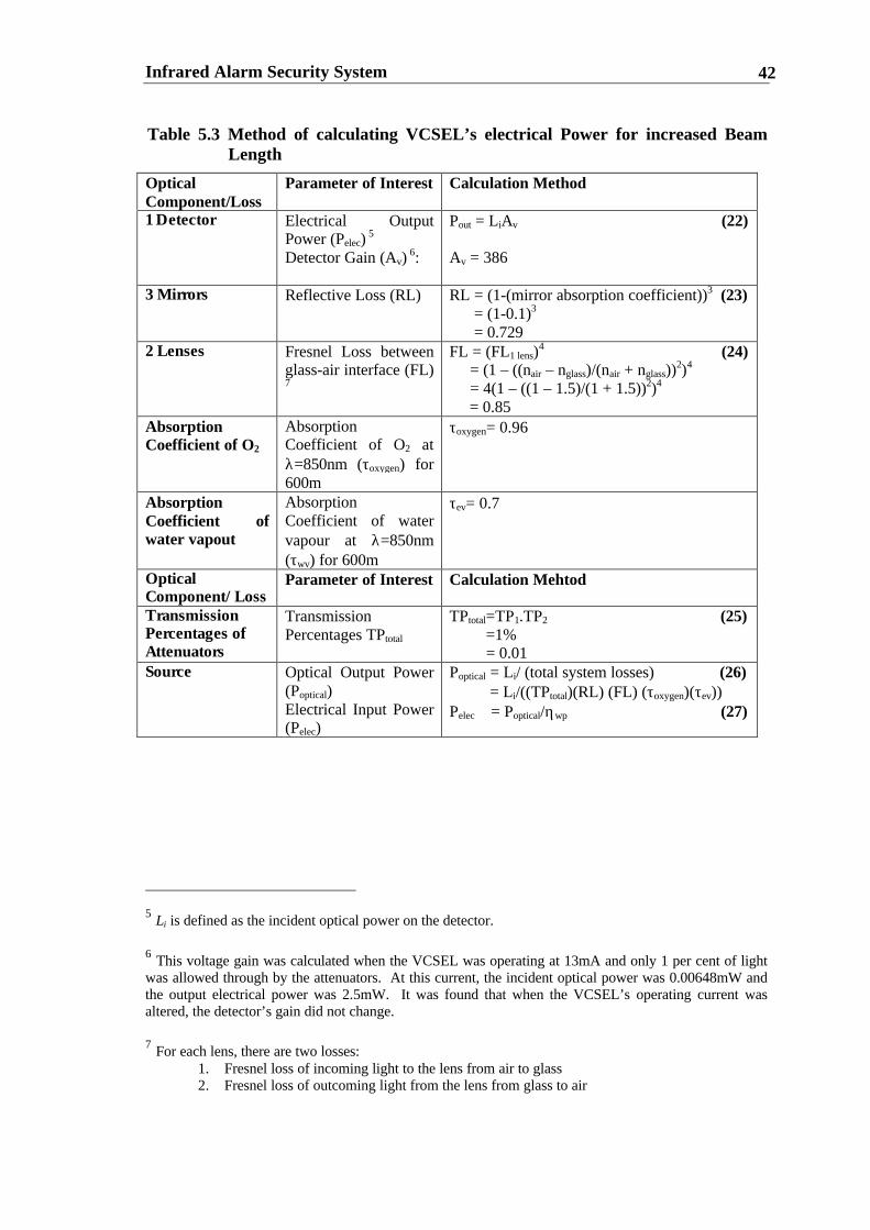
Table 5.3 Method of calculating VCSEL’s electrical Power for increased BeamLength
OpticalComponent/Loss
Parameter of Interest Calculation Method
1 Detector Electrical OutputPower (Pelec)
5
Detector Gain (Av) 6:
Pout = LiAv (22)
Av = 386
3 Mirrors Reflective Loss (RL) RL = (1-(mirror absorption coefficient))3 (23) = (1-0.1)3
= 0.7292 Lenses Fresnel Loss between
glass-air interface (FL)7
FL = (FL1 lens)4 (24)
= (1 – ((nair – nglass)/(nair + nglass))2)4
= 4(1 – ((1 – 1.5)/(1 + 1.5))2)4
= 0.85AbsorptionCoefficient of O2
AbsorptionCoefficient of O2 atλ=850nm (τoxygen) for600m
τoxygen= 0.96
AbsorptionCoefficient ofwater vapout
AbsorptionCoefficient of watervapour at λ=850nm(τwv) for 600m
τev= 0.7
OpticalComponent/Loss
Parameter of Interest Calculation Mehtod
TransmissionPercentages ofAttenuators
TransmissionPercentages TPtotal
TPtotal=TP1.TP2 (25) =1% = 0.01
Source Optical Output Power(Poptical)Electrical Input Power(Pelec)
Poptical = Li/ (total system losses) (26) = Li/((TPtotal)(RL) (FL) (τoxygen)(τev))Pelec = Poptical/ηwp (27)
5 Li is defined as the incident optical power on the detector.
6 This voltage gain was calculated when the VCSEL was operating at 13mA and only 1 per cent of lightwas allowed through by the attenuators. At this current, the incident optical power was 0.00648mW andthe output electrical power was 2.5mW. It was found that when the VCSEL’s operating current wasaltered, the detector’s gain did not change.
7 For each lens, there are two losses:1. Fresnel loss of incoming light to the lens from air to glass2. Fresnel loss of outcoming light from the lens from glass to air

Infrared Alarm Security System 43
The theoretical electrical VCSEL input Power required to monitor 600 metres and
surpass conventional monitoring distances is 14.14mW.8 This power is remarkably low
due to the extremely high sensitivity of the receiver (see Section 7.3).
5.7 CONCLUSION
This Chapter has outlined the optical design theory and optimisation methods involved
for an infrared alarm security system. It showed the advantages of VCSELs over edge
emitting lasers. These advantages included smaller beam divergence, high power
efficiency and cheaper manufacturing costs. The ABCD Matrix method was introduced
to calculate the optimal beam parameters. It was found that d1 was 10cm, d2 was 1.51m
and d3 was 8.5cm. These values were to be expected. The chapter also outlined the
procedure used to calculate the VCSELs electrical input power for a monitoring
distance of 600 metres. It was found to be 14.14mW, a remarkably low input power.
8 This value was calculated using a wall-plug efficiency of 11% (see Section 7.2) and an Li of0.00648mW.

Infrared Alarm Security System 44
CHAPTER SIX
ELECTRICAL DESIGN
6.1 CHAPTER OBJECTIVES:
• Explain the electrical components of the active infrared alarm security
system specified in Chapter Four
• Stress the importance of the electrical simulation programs PSPICE and
LogicWorks in the design process
• Discuss the VCSEL Driver, Receiver Circuit, Power Supply and Alerting
Apparatus.
6.2 IMPORTANCE OF CIRCUIT SIMULATION
6.2.1 PSPICE
SPICE is an acronym for Simulation Program with Integrated Circuit Emphasis. The
program was developed by the Electronics Research Laboratory at the University of
California in the early 1970s [H1]. An enhanced version, called PSPICE Version 8, by
Microsim, is used for this thesis.
The simulation of an electronic circuit using PSPICE is a crucial step in the design
process for analogue circuits. It can save hours of time and money otherwise spent in
prototyping. However, PSPICE should not be used as a substitute for traditional circuit
design.
A Pspice program consists of the following [H1]:

Infrared Alarm Security System 45
1. Program Title
2. Comment statements denoted by *
3. Component statements that describe the circuit topology
4. Model statements that give device parameters
5. Analysis requests
6. Output requests
7. End Statement
6.2.2 LogicWorks
LogicWorks is designed by Capilano Computing Systems Limited. Version 3.0.2 was
used for the simulation. LogicWorks is a simulation program for digital circuits. The
circuit’s operation can be observed by placing logic probes at both inputs and outputs of
the circuit. It is an imperative design tool and can save hours of time otherwise spent
breadboarding.
6.3 VCSEL DRIVER
The VCSEL Driver Circuit is shown in Appendix Two. A photograph of the circuit can
be found in Figure 6.1. The circuit is designed to drive a VCSEL at 1.85V and 13 mA
from a five volt battery power supply. A potentiometer is used to vary the constant
output current. The laser driver consists of a modulator cascaded with a constant
current source.
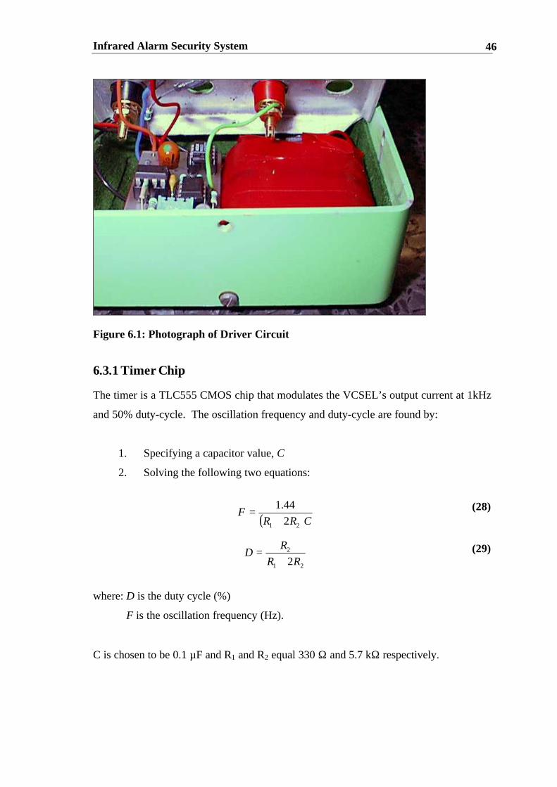
Infrared Alarm Security System 46
Figure 6.1: Photograph of Driver Circuit
6.3.1 Timer Chip
The timer is a TLC555 CMOS chip that modulates the VCSEL’s output current at 1kHz
and 50% duty-cycle. The oscillation frequency and duty-cycle are found by:
1. Specifying a capacitor value, C
2. Solving the following two equations:
where: D is the duty cycle (%)
F is the oscillation frequency (Hz).
C is chosen to be 0.1 µF and R1 and R2 equal 330 Ω and 5.7 kΩ respectively.
(28)
(29)
( )CRRF
21 2
44.1
+=
21
2
2RR
RD
+=

Infrared Alarm Security System 47
6.3.2 Constant Current Source
An operational amplifier configuration is used as the constant current source. The
summing-point constraint, v- = v+ is used to obtain the constant current expression. The
steps taken to arrive at this expression are outlined below:
where: Rsh = Pot1A (from Figure 5.1),
Vsh is the voltage at the transistor’s base
Vcc is the +5V Power Supply
V- is the inverting input of the opamp
V= is the non-inverting input of the opamp
Thus, by varying the potentiometer, a current range from eight to thirty milliamperes is
obtained.
The PSPICE program can be found in Appendix Seven. The output current waveform
is depicted in Figure 6.2 for 15 mA of current.
(31)
(30)
(32)
(33)
(34)
( )
( )5
4
4
5
87
8
54
4
54
5
,
RV
VVRi
R
RVR
vvEquating
R
VVi
RR
RVv
RR
RVV
RR
RVv
i
shccout
ish
sh
shccout
cc
shccin
−=∴
=
=
−=
+=
+−
++
=
+−
+
−

Infrared Alarm Security System 48
6.4 RECEIVER CIRCUIT
The Receiver Circuit comprises of three components:
1. a Silicon IR Light-to-Voltage Sensor
2. a Precision full-phase wave rectifier
3. an Inverter with Schmitt Trigger input.
Figure 6.2: Current Output Waveform of VCSEL driver
An additional fourth component, the battery power supply has also been designed and
prototyped successfully9.
A flow chart of the receiver’s operation is shown in Appendix Seven. The receiver
circuit is shown in Appendix Two. A photograph of this circuit can be seen in Figure
6.3.
9 The battery power supply has not been placed on the final receiver PCB due to time constraints.
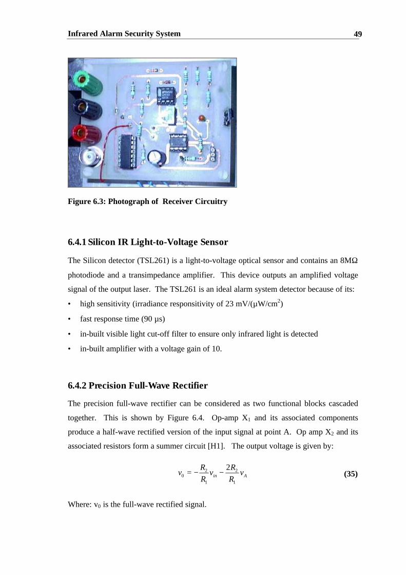
Infrared Alarm Security System 49
Figure 6.3: Photograph of Receiver Circuitry
6.4.1 Silicon IR Light-to-Voltage Sensor
The Silicon detector (TSL261) is a light-to-voltage optical sensor and contains an 8MΩ
photodiode and a transimpedance amplifier. This device outputs an amplified voltage
signal of the output laser. The TSL261 is an ideal alarm system detector because of its:
• high sensitivity (irradiance responsitivity of 23 mV/(µW/cm2)
• fast response time (90 µs)
• in-built visible light cut-off filter to ensure only infrared light is detected
• in-built amplifier with a voltage gain of 10.
6.4.2 Precision Full-Wave Rectifier
The precision full-wave rectifier can be considered as two functional blocks cascaded
together. This is shown by Figure 6.4. Op-amp X1 and its associated components
produce a half-wave rectified version of the input signal at point A. Op amp X2 and its
associated resistors form a summer circuit [H1]. The output voltage is given by:
Where: v0 is the full-wave rectified signal.
(35)Ain vR
Rv
R
Rv
1
2
1
20
2−−=

Infrared Alarm Security System 50
Figure 6.4: Breakup of Precision full-wave rectifier
The precision full-wave rectifier converts the voltage square wave into a constant DC
voltage output. This is shown by the PSPICE simulation in Figure 6.5 when the peak
input voltage equals 2 V. Note that the DC voltage is only half the peak modulation
voltage. Increasing the resistance of the potentiometer, R8 (refer to schematic in
Appendix Two), boosts the DC voltage.
Figure 6.5: PSPICE simulation of full-wave precision rectifier
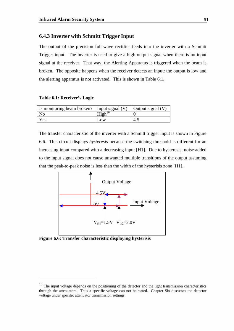
Infrared Alarm Security System 51
6.4.3 Inverter with Schmitt Trigger Input
The output of the precision full-wave rectifier feeds into the inverter with a Schmitt
Trigger input. The inverter is used to give a high output signal when there is no input
signal at the receiver. That way, the Alerting Apparatus is triggered when the beam is
broken. The opposite happens when the receiver detects an input: the output is low and
the alerting apparatus is not activated. This is shown in Table 6.1.
Table 6.1: Receiver’s Logic
Is monitoring beam broken? Input signal (V) Output signal (V)No High10 0Yes Low 4.5
The transfer characteristic of the inverter with a Schmitt trigger input is shown in Figure
6.6. This circuit displays hysteresis because the switching threshold is different for an
increasing input compared with a decreasing input [H1]. Due to hysteresis, noise added
to the input signal does not cause unwanted multiple transitions of the output assuming
that the peak-to-peak noise is less than the width of the hysterisis zone [H1].
Figure 6.6: Transfer characteristic displaying hysterisis
10 The input voltage depends on the positioning of the detector and the light transmission characteristicsthrough the attenuators. Thus a specific voltage can not be stated. Chapter Six discusses the detectorvoltage under specific attenuator transmission settings.
Input Voltage
Output Voltage
+4.5V
0V
Vth1=1.5V Vth2=2.0V

Infrared Alarm Security System 52
6.5 BATTERY POWER SUPPLY FOR VCSEL DRIVER AND
RECEIVER
The Battery Power Supply is shown in Appendix Two. The MAXIM 631, a step-up
converter, is used to boost 3 V input Voltage from two C batteries in series to 5 V @
100 mA. The laser driver draws 88 mA, whilst the receiver and Alerting Apparatus
only draw 50 mA. Due to this low current consumption, the battery life is prolonged
(7750 mA hours [F1]). An ON/OFF switch is used to activate the power supply. The
LED power indicator light is activated when the Power Switch is turned on. Both the
laser driver and receiver draw currents less than 100mA.
6.6 ALERTING APPARATUS
The alerting apparatus is a digital circuit that drives a buzzer when the beam is broken.
The buzzer’s output is 76 dB at 30 cm away from the source. Once the beam refocusses
on the detector, a counter is activated.11 This ensures that the buzzer is active for an
additional amount of time (the delay time), to warn the intruder and others that a break-
in has occurred. The delay time is determined by the clock frequency, 0.375 Hz and is
given by:
)(16)( HzfrequencysTimeDelay ×=
The alerting apparatus is shown in Appendix Two. A photograph of the durable casing
of the alerting apparatus can be found in Figure 6.7.
11 The counter was simulated using a program called LogicWorks. The disk containing the file a:\countercan be found in Appendix Seven.
(36)

Infrared Alarm Security System 53
Figure 6.7: Durable Casing of Alerting Apparatus
6.7 CONCLUSION
This chapter has dealt with the electrical design of the alarm security system. The
transmitter consisted of a modulator cascaded to a constant current source. The receiver
rectified the input modulation signal by using a full-wave precision rectifier. The
alerting apparatus was a digital circuit that had a specified delay time to alert the
intruder that the beam had been broken. A power supply was also presented that
regulated 3V DC to 5V DC. Throughout the design process, the importance of PSPICE
and LogicWorks were shown as imperative simulation tools in the prototyping stage of
electrical design. The utilisation of these tools maximised time efficiency.

Infrared Alarm Security System 54
CHAPTER SEVEN
RESULTS AND DISCUSSION
7.1 CHAPTER OBJECTIVES:
• Present an analysis of the security alarm system and its components
• Analyse the performance of the VCSEL and detector
• Determine the system’s maximum monitoring distance by evaluating the
detector’s noise equivalent power for an operational VCSEL current of
13mA12
• Determine if the system’s specifications were achieved.
7.2 VCSEL PERFORMANCE
7.2.1 Far Field Distribution and associated full angle beam divergence
The Far Field Distribution of the VCSEL (driven at 13mA) is used to calculate the
divergence of the laser beam. The VCSEL is placed on a rotating stand and its beam is
directed towards the pinhole. The angle positioning of the VCSEL and the laser’s
output power behind the pinhole are then measured13. This setup is shown in Figure 7.1.
12 13mA was chosen as it gave the maximum allowable current at the detector of 10mA.
13 The pinhole ensures that the optical wattmeter detects the beam’s maximum irradiance.
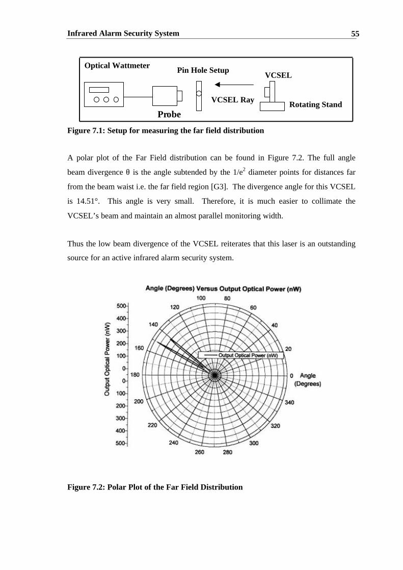
Infrared Alarm Security System 55
Figure 7.1: Setup for measuring the far field distribution
A polar plot of the Far Field distribution can be found in Figure 7.2. The full angle
beam divergence θ is the angle subtended by the 1/e2 diameter points for distances far
from the beam waist i.e. the far field region [G3]. The divergence angle for this VCSEL
is 14.51°. This angle is very small. Therefore, it is much easier to collimate the
VCSEL’s beam and maintain an almost parallel monitoring width.
Thus the low beam divergence of the VCSEL reiterates that this laser is an outstanding
source for an active infrared alarm security system.
Figure 7.2: Polar Plot of the Far Field Distribution
Optical Wattmeter
Probe
VCSEL RayRotating Stand
VCSELPin Hole Setup

Infrared Alarm Security System 56
7.2.2 DC Electrical and Optical Characteristics
The electrical and optical characteristics of the VCSEL measured were:
1. output Voltage, V (V)
2. output Current, I (mA)
3. output Optical Power, L (mW)
4. wall-plug efficiency, ηwp (%)
They are shown in Figure 7.3. The V-I-L curve was measured by recording the voltage
across the VCSEL as the current was varied; the L was obtained by placing an optical
power metre (ANDO AQ-135E) as close as possible to the VCSEL. The optical power
readings were then taken as the current was varied.
The wall plug efficiency was calculated using the following formula:
Figure 7.3: VCSELs V-I-L-ηηwp relationship
(37)
ηwp
L
V
DC I-V-L-Wallplug Efficiency
0
2
4
6
8
10
12
0 5 10 15 20 25
Current (mA)
Volta
ge (V
)W
allp
lug
Effic
ienc
y (%
)
0
0.5
1
1.5
2
2.5
3
3.5
4
4.5
Opt
ical
Out
put P
ower
(mW
)
V
ηwp
L
I-V-L-ηηwp VCSEL Characteristics
%100
%100
×=
×=
VI
L
PowerinputElectrical
Lwpη

Infrared Alarm Security System 57
From the graph, an optimal wall-plug efficiency of 11.4% was obtained at 14mA drive
current. This is a quite a respectable efficiency for lasers today [S3] The threshold
current and voltages14 are 3.6mA and 1.45V. These small threshold values indicate the
beauty of the VCSEL’s low input electrical power capacity and demonstrate why this
laser is such a superb alarm source.
7.2.3 Spectrum Analysis
A spectrum analysis was taken for the VCSEL. The set up is shown in figure 7.4. The
spectrum can be found in figure 7.5. The laser was driven at 13mA constant current.
The output signal from the amplifier was taken to an RF Spectrum analyser, the
ADVANTEST R4131D.
Figure 7.4: Experimental setup for Spectrum Analysis
14 The threshold values are the minimum values required for lasing to occur.

Infrared Alarm Security System 58
Figure 7.5: VCSEL’s Spectrum
Two TEM (transverse electric and magnetic) modes exist in the VCSEL’s spectrum:
1. The fundamental mode – TEM00 at a wavelength of 858.14nm;
2. The first transverse mode – TEM10 at a wavelength of 858.29nm.
The mode patterns are shown in Figure 7.6.
Figure 7.6: Mode Patterns
Thus, the laser is multimode.
Spectrum Analysis
0
2000
4000
6000
8000
10000
12000
14000
16000
18000
856.5 857 857.5 858 858.5 859 859.5 860 860.5
Wavelength (nm)
Sp
ectr
al In
ten
sity
(A
rbit
rary
Un
its)

Infrared Alarm Security System 59
7.3 SYSTEM AND RECEIVER PERFORMANCE
The infrared system is designed around the characteristics of the infrared detector. This
section discusses seven issues pertaining to the effectiveness of the system’s and
receiver’s performance. The results were taken for a driver VCSEL current of 13mA, a
room temperature of 22°C and a monitoring distance of 160m15. The issues are:
Issue One: The system’s limits that results when the VCSELs’ signal voltage
is equal to the detector’s noise voltage
Issue Two: The signal obtained per unit radiant power falling on the detector
Issue Three: The width of the monitoring beam
Issue Four: The system’s response time
Issue Five: The safety of the system
Issue Six: System’s Durability
Issue Seven: System’s Cost
7.3.1 Noise Equivalent Power: Determining the Limts
The Noise Equivalent Power, NEP, is used to calculate the system’s monitoring limit.
The NEP is the input optical power at the detector when the detector’s Signal to Noise
Ratio is equal to 1 [I1] [K1][G2].
The noise equivalent power, NEP, is given by:
15 The results taken in this section were for a simulated monitoring distance of 160m. This monitoringdistance is due to the series combination of attenuators that only allow 1% of light transmission throughfrom the laser to the detector.
( )1-mW.Hz 1
fV
VEANEP
S
ND
∆
= (38)

Infrared Alarm Security System 60
where: Ad is the area of the detector = 0.5 mm2
VN is the noise voltage = 0.25nV @ 1 kHz
VS is the VCSEL DC signal voltage = 1.85 V @ 13 mA
∆f is the bandwidth = 1000 Hz
E is the irradiance (mW/mm2) = 0.01296 mW/mm2
Thus, by substituting these values into equation (38), the NEP is equal to 0.5473µW.
This NEP value is very good and indicates that only a small amount of incident optical
power is required at the receiver to effectively detect a signal.
The maximum monitoring distance is calculated by considering the system losses and
the absorption coefficients of oxygen and water vapour. The calculation assumes an
input VCSEL current of 13mA. It is based on the same methodology used in Section
5.6.
The maximum VCSEL input electrical power at 13mA driver current is 24.05 mW (i.e.
Operating Current multiplied by output Voltage). The VCSEL’s output optical power
is calculated by multiplying the laser’s incident electrical power by its wall-plug
efficiency, 11% at 13mA. This gives an output optical power of 2.645 mW.
Alternatively, this value could be interpolated from Figure 7.3
Now that the optical power of the source and the incident power of the detector are
known, the total losses throughout the system (System Losses) can be calculated. This
is shown in (39).
0.0002 645.2
5437.0
=
=
=
mW
W
LaserOfPowerOpticalOutput
DetectorOfPowerElectricalInputLossesSysteml
µ (39)
Infrared Alarm Security System 61
This value is to be expected. It incorporates losses associated with the attenuators (loss
of 1%), absorption coefficients and optical components.
Next, the system losses neglecting absorption by oxygen and water vapour are
considered. They can be calculated from Table 5.3. These losses are:
1. Reflective losses of the mirror = 0.729
2. Fresnel losses associated with the thin lenses = 0.85
3. Transmission losses associated with the attenuators = 0.01.
All three losses are multiplied together to give system losses ex absorption of 0.0062.
Finally, the absorption losses can be calculated. This is done by realising that the
system losses are equal to the system loss ex absorption multiplied by absorption losses.
An absorption loss of 32% is calculated. This results in a staggering maximum
monitoring distance of approximately 950 metres with only 24.05mW of electrical
power supplied to the VCSEL. 16.
7.3.2 Responsivity of Detector
The responsivity, R of the detector is defined as the rms signal current Is per unit rms
radiant power P incident upon the detector. It is given by:
The responsivity is extremely high and is a strong player in the outstanding performance
of the system.
16 Fog and dust intervention have been neglected for this calculation
mWAmW
mA
L
IR
i
s
/2 00648.0
13
=
=
=
(40)

Infrared Alarm Security System 62
7.3.3 Width of Monitoring Beam
The monitoring beam width was obtained by viewing the collimated laser beam on an
infrared card and measuring its diameter. It was found to be 1.5cm. Even though this
is a reasonable size, the beam’s diameter could be increased by using a lens with a
larger focal length.
7.3.4 Response Time
The response time is the time taken for the Alerting Apparatus to activate when the
beam is cut. The system’s response time is in adherance with the Australian Standard
2201.3-1991. That is, the detector initiates an alarm as a result of the complete
interruption of the signal received for any period longer than 40ms and does not activate
the alarm for a period shorter than 20ms.
7.3.5 Safety Criteria
The allowable MPE to the eye is 0.24075 mW/mm2 according to AS/NZS 2211.1:1997 .
Working on the formula irradiance = input optical power (mW)/ocular surface area
(mm2), the calculation based on the premise of a cornea17 gives the following result for
a laser operating at 13mA:
Thus, if the laser beam intercepted a cornea, it would cause no problem to the eye. The
system would not harm the skin as its MPE does not exceed the skin’s MPE specified
by the Australian Standard AS/NZS 2211.1:1997.
17 The area of a cornea is 13.2mm2[W1]
MPE allowable
/189.0
2.13
5.2
2
⟨=
=
=
mmmW
mm
mW
A
pMPE
surfaceocular
laser
(41)

Infrared Alarm Security System 63
7.3.6 System’s Durability
The system’s durability is judged on:
1. Its overall sturdiness
2. It’s effectiveness in hot and wet environments
Addressing Issue One: The system’s shielding components for the laser driver and
alerting apparatus are made of a sturdy tough metal. This has been shown in the
Electrical Design Chapter. Due to time constraints, it was not possible to make a
similar casing for the detector. However, the receiver must incorporate a hard metal
casing if the prototyped product is to be developed to the commercial level.
Addressing Issue Two: It was impossible to expose the system to extreme weather
temperatures. However, the components used for this system were all capable of
functioning to their fall capacity under extreme temperature variations, from–10 to 65
degrees Celsius. Based on this, the system is expected to be highly resilient to dramatic
temperature changes and should work effectively. Dust particles from a dirty cloth were
used to simulate the beam intervention that small rain drops may have on the system..
The system was unaffected by these dust particles.
7.3.7 System’s Costing
The system’s cost can be found in Appendix One. The cost of the complete system is
$191.84. This is an extremely competitive price for a system that has low power
consumption and can monitor a distance of 950 metres.
7.4 CONCLUSION
All system’s specifications were met. The system improved on existing technology
through its durability and cost-effectiveness. The system also performed well under

Infrared Alarm Security System 64
simulated conditions of dust intervention and light transmission limitations imposed by
the attenuators. An excellent monitoring distance of 950 metres was achieved with a
low input power of 24.05 mW.

Infrared Alarm Security System 65
CHAPTER EIGHT
CONCLUSION
8.1 SUMMARY
This thesis has focussed on the design and implementation of an active infrared alarm
security system. The active infrared system was chosen over its passive counterpart
because it could operate in harsher environments. The system was measured to have an
excellent noise equivalent power, NEP of 0.5473 µW. This meant that only 0.5473 µW
of incident optical power on the detector was required to detect the VCSEL’s signal.
The system was capable of monitoring a distance of 950m (excluding fog intervention).
The system built consisted of Vertical Cavity Surface Emitting Laesr (6µm diameter)
driver circuitry, a system of mirrors, lenses and attenuators, a receiver circuit (Silicon
detector with a detection area of 0.5mm2) and alerting apparatus.
The thesis first considered the motivation for undertaking the design of an active
infrared alarm security system:
1. To realise the system’s industrial potential
2. To understand the commercial market and relevant Australian Laser and
Alarm Standards
3. To rise to the challenge of setting goals and successfully achieving them
4. For the fascination of integrating physical and optical principles into a usable
state of the art detection apparatus.
5. To capitalise on the drawbakcs of commercial systems
The thesis then reviewed current existing technology, and found that a niche existed in
the market that the active alarm system could exploit. It was found that existing
Infrared Alarm Security System 66
systems were very expensive and lacked durability. The new system is very cheap
($191.84) and has been designed to operate in very hot, wet, windy and humid
environments. This is because the system is an active infrared one and has strong
casing surrounding the vital components.18
Relevant Australian Laser Safety and Alarm Standards were reviewed. Specifications
were then set based on the system’s objectives, relevant Australian Standards and
drawbacks that exist in commercial active infrared systems. The maximum permissable
exposure to the cornea, 0.24075 mW/mm2 and the skin, 6580 mW/mm2 was not
exceeded by the system. Thus, the system design was safe.
The response time of the system adhered to the Australian Standard 2201.3-1991. That
is, the detector successfully initiated an alarm as a result of the complete interruption of
the signal received for any period longer than 40 ms and did not activate the alarm for a
period shorter than 20 ms.
Optical Design Theory and optimisation methods were presented. VCSELs were
compared to edge emitting lasers. VCSELs had a smaller divergent and symmetric
beam, were cheaper to manufacture and had a much lower power consumption than
their edge-emitting counterparts.
Optical Optimisation methods incorporated the use of the ABCD matrix law to calculate
the beam’s parameters. Optical optimisation dealt with beam collimation and optimising
the system’s performance. The beam was said to be collimated when the maximum
distance between the source and Lens 1 and the detector and Lens 2 equalled the lens’s
focal length. The system’s performance was optimised by focussing the beam on to
ninety per cent of the detector. In this section, a method was presented to calculate the
monitoring distance of 600 metres and surpass conventional monitoring distances.
System losses and absorption losses of oxygen and waver vapour were taken into
consideration.
18 A hard casing was not designed for the prototype detector circuit for this thesis. However, for the finalproduct, the hard case would be implemented with ease.
Infrared Alarm Security System 67
The system’s electrical design was discussed. Chapter Five stressed the importance of
circuit simulation programs such as PSPICE and LogicWorksas tools that maximised
time efficiency. in the design process. The VCSEL driver, receiver and alerting
apparatus circuitry were discussed in detail. A battery-powered supply for all three
modules was designed.
Chapter Six dealt with the system’s analysis. It was found that the VCSEL had a full
angle beam divergence of 14.51°. The threshold voltage and current of the VCSEL
were 1.45 V and 3.6 mA respectively. An optimal wall-plug efficiency of 11.4% was
achieved at 14 mA. The system was also analysed and a maximum monitoring distance
of 950 m was calculated when the Signal to Noise Ratio equalled one. The monitoring
distance of the prototype security system far exceeded the maximum limit of 600 m of
of commercial conventional systems.
In conclusion, the active infrared alarm security system was a success. It satisifed all
objectives and worked very effectively.
8.2 FUTURE WORK
Despite the success of the project, further work is possible to extend the capabilities of
the system.
A) Design an intelligent active alarm system that activates various alarm tones
based on the interruption time of the signal and distinguishes between pets
and intruders
B) Design hardware and software that constantly monitors the alarm system and
informs a host computer of its current status
C) Evaluate the extent to which dust particles, leaves, and loose soil particles
hinder the performance of the system and incorporate this into the maximum
monitoring distance of the system

Infrared Alarm Security System 68
D) Analyse and model the effect that varying detector size and VCSEL
diameters have on system performance
E) Design a flashing light that informs intruders that the system is activated.

Infrared Alarm Security System 69
REFERENCES
A1. Aronson, L.B., Lernoff, B.E., Giboney, K.S., “The Ideal Light Source for Data
Nets”, IEEE Spectrum, Feb., 1998, pp 43-53.
A2. AS 2201.3 – 1991, Intruder alarm system—Part 3: Detection devices for internal
use.
A3. AS 2201.4 – 1990, Intruder alarm system—Part 4: Wire-free systems installed in
client’s premises.
A4. AS 2201.5 – 1992, Intruder alarm systems—Part 5: Alarm transmission systems.
A5. AS/NZS 2211.1: 1997, Laser Safety—Part 1: Equipment classification,
reuirements and user’s guide.
C1. Choquette, K.D., Hou, H.Q., “Vertical Cavity Surface Emitting Lasers: Moving
from Research to Manufacturing”, Proc. IEEE, vol. 85, No. 11, Nov. 1997, pp
1730-1939.
C2. Cohen, M., Vertical cavity surface emitting lasers and their applications to
optical computing, Brisbane: [St. Lucia, Qld.], 1995.
D1. Desmarais, L., Applied electro-optics, Upper Saddle River, N.J. : Prentice Hall,
1998.
E1. Ebeling, K.J., Integrated optoelectronics : waveguide optics, photonics,
semiconductors, Berlin ; New York : Springer-Verlag, 1993.
F1. Farnell Electronics Catalogue, pp 4, 1998.

Infrared Alarm Security System 70
F2. Feinberg, G., “The Electromagnetic Spectrum,” The World Book Encyclopedia,
Field Enterprises , pp158-159, 1975.
G1. Gerrard, A., Introduction to matrix methods in optics, London ; New York :
Wiley, 1975.
G2. Gopel, W., Hesse, J., Zemel, J.N., Sensors : a comprehensive survey, Weinheim,
Germany ; New York, NY, USA : VCH, 1989.
G3. Guenther, R.D., Modern optics, New York : Wiley, 1990.
H1. Hambley, A.R., Electronics : a top-down approach to computer-aided circuit
design, Englewood Cliffs, N.J. : Prentice Hall, 1994.
H2. Hellwege K.H., Madelung O., “Physical and Chemical Properties of the Air,”
Landolt-Bornstein, vol 4-b, pp 138-142, 1998.
I1. Infrared Information and Analysis (IRIA) Center, The infrared handbook,
Washington : The Office, 1978.
K1. Kruse, P. W., Elements of infrared technology : generation, transmission, and
detection, New York : Wiley, 1962.
N1. Nussbaum, A., Geometric Optics : an introduction, Reading, Mass. : Addison-
Wesley Pub. Co, 1968.
O1. O'Shea, D.C., Elements of modern optical design, New York : Wiley, c1985.
P1. Pulnix America Inc., Unit 16, 35 Garden Road, Clayton, 3168 Victoria, Australia.
R1 RS Components Catalogue, July 1998.
Infrared Alarm Security System 71
S1. Sale, T. E., Vertical cavity surface emitting lasers, Taunton, Somerset, England :
Research Studies Press ; New York : Wiley, 1995.
S2. Saunders, G., retired army alarm system security specialist.
S3. Senior, J., Optical Fibre Communications, New York : McGraw-Hill Book,
1981.
T1. Tech Logistics, Inc. 955 Belmont Avenue, North Haledon, NJ 07508. Email:
V1. Verdeyen, J.T., Laser Electronics, Englewood Cliffs, N.J. : Prentice-Hall, 1995.
W1. Wolf T., The Anatomy of the eye and Orbit, New York: Prentice Hall, 1965.
W2. Wright, H.C., Infrared techniques, Oxford : Clarendon Press, 1973.

Infrared Alarm Security System 72
Appendix One: System Costing
A1.1 VCSEL Driver
DeviceDescription
Device Model Cost/Item ($) Supplier Number ofItems
Totalcost($)
VCSEL HFE4081 80.00 Honeywell 1 80.00Op-Amp 1 UA741 1.04 RS 1 1.04Modulator Chip TLC555 1.24 RS 1 1.24NPN Transistor 2N222A 0.74 RS 1 0.74Resistor 330 Ohm 0.14 RS 1 0.14Resistor 1k 0.14 RS 1 0.14Resistor 4.7k 0.14 RS 1 0.14Resistor 100 Ohm 0.14 RS 2 0.28Resistor 100k 0.14 RS 1 0.14Resistor 1k Pot 1.95 RS 1 1.95Resistor 47 Ohm 0.14 RS 1 0.14Diode 1N748A 0.75 RS 1 0.75Capacitor non-polarised
0.01µF 0.48 RS 1 0.48
Capacitor non-polarised
0.01µF 0.48 RS 1 0.48
TOTALCOST
$87.40
Table A1.1: Components and Costing of VCSEL driver
A1.2 Receiver
DeviceDescription
DeviceModel
Cost/Item($)
Supplier Number ofItems
Total cost($)
SiliconDetector
TSL261 5.55 RS 1 5.55
Op-Amp 2 LMC6042 4.99 RS 1 4.99SchmittTrigger
74LS14 0.90 RS 1 0.90
Resistor 1k 0.14 RS 3 0.42Resistor 33 Ohm 0.14 RS 1 0.14Resistor 47 Ohm 0.14 RS 1 0.14Resistor 1M Pot 1.95 RS 1 1.95Capcitorpolarised
100µF 0.48 RS 1 0.48
TOTALCOST
$14.57

Infrared Alarm Security System 73
Table A1.2: Components and Costing of Receiver
A1.3 Alerting Apparatus
DeviceDescription
DeviceModel
Cost/Item($)
Supplier Number ofItems
Total cost($)
Buzzer Pico Buzzer 8.00 RSComponents
1 8.00
ModulatorChip
TLC555 1.24 RS 1 1.24
OR gates 74LS32 0.87 RS 1 0.87AND gates 74LS08 0.99 RS 1 0.99Inverter 74LS04 0.87 RS 1 0.87Counter 74LS161 1.77 RS 1 1.77
TOTALCOST
$13.74
Table A1.3: Components and Costing of Alerting Apparatus
A1.4 Battery Supply
DeviceDescription
DeviceModel
Cost/Item($)
Supplier Number ofItems
Total cost($)
Step-Up DCto DCConverter
Maxim 631 12.25 Farnell 3 36.75
2 C batteries DuracellBattery
2.00 CrazyClarks
3 6.00
LED 3mm LED 0.282 Farnell 3 0.85ON/OFFSwitch
Double PoleDoubleThrow
2.50 Dick Smith 3 7.50
CapacitorPolarised
100nF 0.45 RS 3 1.35
Inductor 33µH 1.42 Farnell 3 4.26Resistor 47 Ohm 0.14 RS 3 0.42
TOTALCOST
$57.13
Table A1.4: Components and Costing of Battery-Power Supply
A1.5 Optical Components
DeviceDescription
DeviceModel
Cost/Item($)
Supplier Number ofItems
Total cost($)
Mirror PlanarMirror
3.00 EngineeringOptics Lab
3 9.00
Thin Lens Focal lengthof 10cm
2.00 EngineeringOptics Lab
2 4.00

Infrared Alarm Security System 74
Holders Holders 6.00 EngineeringOptics Lab
1 6.00
TOTAL
COST
$19.00
Table A1.5: Components and Costing of Optical System
Total System Cost = $191.84

Infrared Alarm Security System 75
Appendix Two: Schematics
A2.1 VCSEL Driver

Infrared Alarm Security System 76
A2.2 Receiver

Infrared Alarm Security System 77
A2.3. Battery Power Supply

Infrared Alarm Security System 78
A2.4 Alerting Apparatus

Infrared Alarm Security System 79
Appendix Three: Gaussian Beams
A3.1 The Wave Equation
The Gaussian Beam concept arises from solving the time independent Helmholz Wave
Equation given by:
where: ψ is the Wave Function
k is the wave number
r is a cylindrical co-ordinate
One solution is:
where
where w0 is the minimum beam width of the Gaussian Beam
R(z) denotes the radius of the spherical equiphase surfaces.
k, is the wave number
(42)
(43)
(44)
(45)
(46)
02)(1
=∂∂
−∂∂
∂∂
zkj
rr
rr
ψψ
phase radial )(2
exp
phase allongitudin )(tanexp
factor amplitude )(
exp),,(
2
0
1
2
20
0
×
×
−
=
zR
kr-j
z
zkz--j
zw
r
w(z)
w
E
zyxE
-
( )
0
20
0
2
0
2
0
20
2
z
1
1)(
λπnw
z
zzzR
z
zwzw
=
+=
+=

Infrared Alarm Security System 80
z is distance from the waist of the beam
A3.1.1 Amplitude of Field
The amplitude of the field changes as the beam propagates along z. The 1/e point is
defined by w0/2, where w(z) is known as the beam width [V1]. Figure A1.1 shows the
origin of the phase front curvature. In this diagram, z is the distance from the waist of
the beam. Figure A1.2 shows the Gaussian beam profile of a TEM0,0 mode.
Figure A3.1: Origin of the phase front curvature
Figure A3.2: Gaussian beam profile of a TEM0,0 mode.

Infrared Alarm Security System 81
A3.1.2 Longitudinal Phase Factor
The Longitudinal Phase Factor shows that the phase of the wave travelling in the
positive Z direction is not constant. It is given by:
where k, the wave number of a uniform plane wave = wn/c.
The radial phase factor indicates that the lines of constant phase are spheres [C2]. Thus
for a plane perpendicular to the z axis, the phase is always varying. It is given by:
where R(z) denotes the radius of the spherical equiphase surfaces.
A3.1.3 Spot Size of Beam
The beam width, w(z), increases directly with the magnitude of z. The Spot size of the
beam occurs when w is at its smallest value. This is where z is defined to be zero. This
is illustrated in Figure A1.1.
A3.1.4 Divergence angle
The divergence angle is shown also in Figure A1.1 As the width grows as the wave
propagates, in the limit as z approaches to infinity, w(z) has a linear asymptote given by
[V1]:
where θ0 is called the Divergence or far field angle of the beam.
(47)
(48)
(49)
−=
0
1-tanz
zkzLφ
)(2/2 zRkrR =φ
nw00
2
πλ
θ =
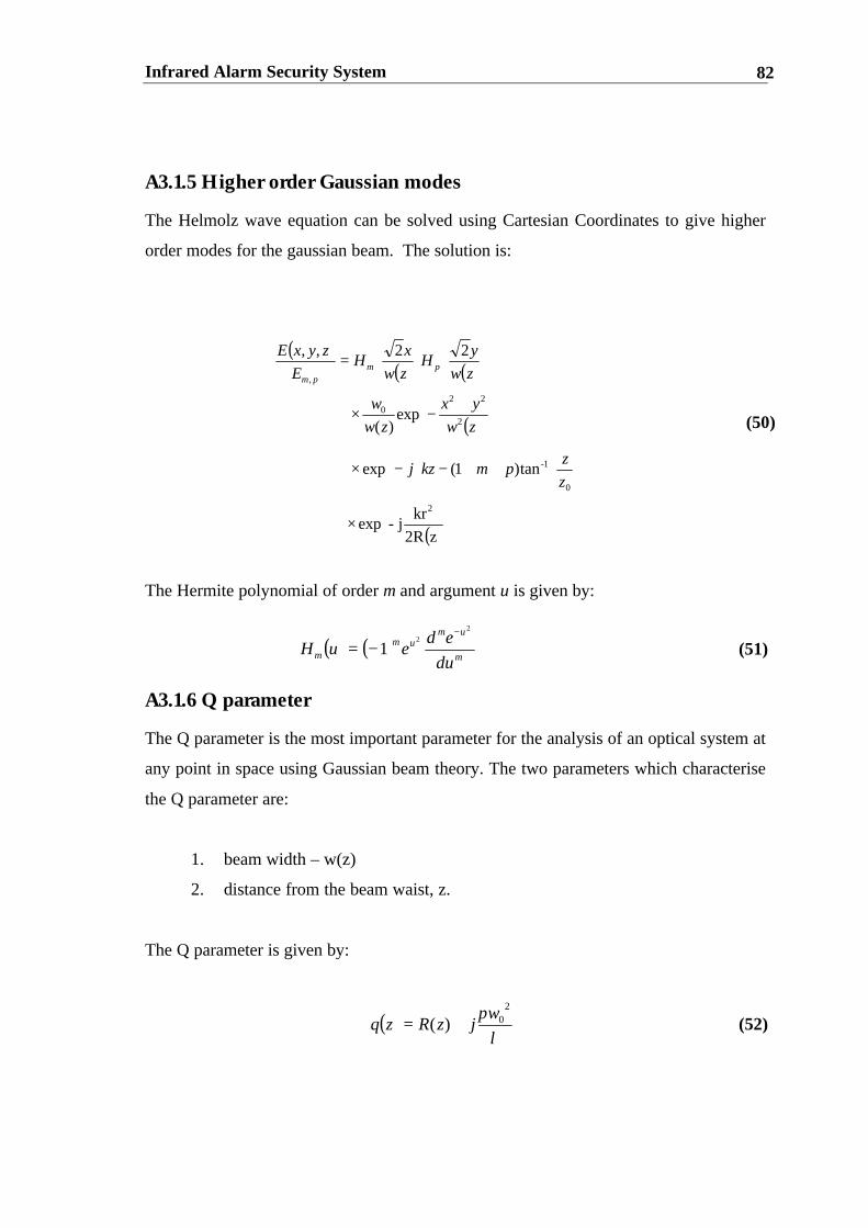
Infrared Alarm Security System 82
A3.1.5 Higher order Gaussian modes
The Helmolz wave equation can be solved using Cartesian Coordinates to give higher
order modes for the gaussian beam. The solution is:
The Hermite polynomial of order m and argument u is given by:
A3.1.6 Q parameter
The Q parameter is the most important parameter for the analysis of an optical system at
any point in space using Gaussian beam theory. The two parameters which characterise
the Q parameter are:
1. beam width – w(z)
2. distance from the beam waist, z.
The Q parameter is given by:
(50)
(51)
(52)
( )( ) ( )
( )
( )
×
++−−×
+−×
=
z2R
krj-exp
tan)1(exp
exp)(
22,,
2
0
1-
2
220
,
z
zpmkzj
zw
yx
zw
w
zw
yH
zw
xH
E
zyxEpm
pm
( ) ( )m
umum
mdu
edeuH
2
2
1−
−=
( )λ
π 20)(
wjzRzq +=

Infrared Alarm Security System 83
A3.1.7 ABCD Law for Gaussian Beams
The ABCD Law for Gaussian Beams is an excellent tool for calculating parameters
such as beam width, lens focal length and spacing dimensions for an optical system.
The ABCD law relates the complex beam parameters q2 of a Gaussian beam at plane 2
to the value q1 at plane 1[V1]. Thus,
Consider the optical system shown in Figure A1.2. The system has one input ray and
one output ray. The input and output rays are specified by their heights y1 and y2 and
slopes y11 and y2
1 respectively measured relative to the optical axes [V1].
The output ray is a function of the input ray such that:
A Taylor series expansion is done on the above equation and only the linear terms are
kept. The constant terms disappear by choosing the correct optical axes orientations and
positions [G1]. Thus:
The ABCD matrix is called the transmission matrix. The ABCD matrix for free space of
length z is given by:
(53)
(54)
(55)
(56)
DCq
BAqq
++
=1
12
( )( )1
1121
2
11112
,
,
yyfy
yyfy
=
=
=
1
1
11
2
2
y
y
DC
BA
y
y
=
10
1
space free
z
DC
BA

Infrared Alarm Security System 84
The ABCD matrix for a thin lens of focal length f is given by:
The thin lens’ power, P is given by:
(57)
(58)
−=
1
101
lensthin fDC
BA
fP
1=

Infrared Alarm Security System 85
Appendix Four: Mathematica Code
*clears past entries*Clear[w0,w1,d1,z1,z,y,x,q0,lamda]
*Initialisation**sets d1 to 10cm*d1=0.1*sets lamda to 850nm*lamda=850 10^-9*beam width of VCSEL is 6um*w0=6 10^-6*beam width at detector is 1.8mm*w1=0.0018q0=-I lamda/pi w0^2pi = N[Pi,3]*focal length of lens is 10cm*f=0.1
*specify abcd matrix*a=1-d3/f-d2/f+(d2 d3)/(f f)-d3/fb=d1 - (d1 d3)/f - (d1 d2)/f + (d1 d2 d3)/(f f) - (d1 d3)/f + d3 - (d1 d2)/f + d2c=-2/f + d2/(f^2)d=-(2 d)/f + (d1 d2)/(f f) + 1 - d2/f
*define functions for q parameter*F[d1_,d2_,d3_,q0_,f_]:=c + d/q0G[d1_,d2_,d3_,q0_,f_]:= a + b/q0H[d1_,d2_,d3_,q0_,f_] := F[d1,d2,d3,q0,f]/G[d1,d2,d3,q0,f]Together[H[d1,d2,d3,q0,f]]x=ComplexExpand[H[d1,d2,d3,q0,f]]
*separate equation into its real part*MyRe[x_] := ComplexExpand[x /. I r_ -> 0]y=MyRe[x]
*separate equation into its imaginary part*z=x-yz1=Together[z/I]
*solve the equation*Solve [ y == 0, z1 == -pi w1^2/lamda, d2,d3 ]

Infrared Alarm Security System 86
Appendix Five: Data Sheets
A5.1 VCSEL Datasheet

Infrared Alarm Security System 87
A5.2 Silicon Detector Datasheet
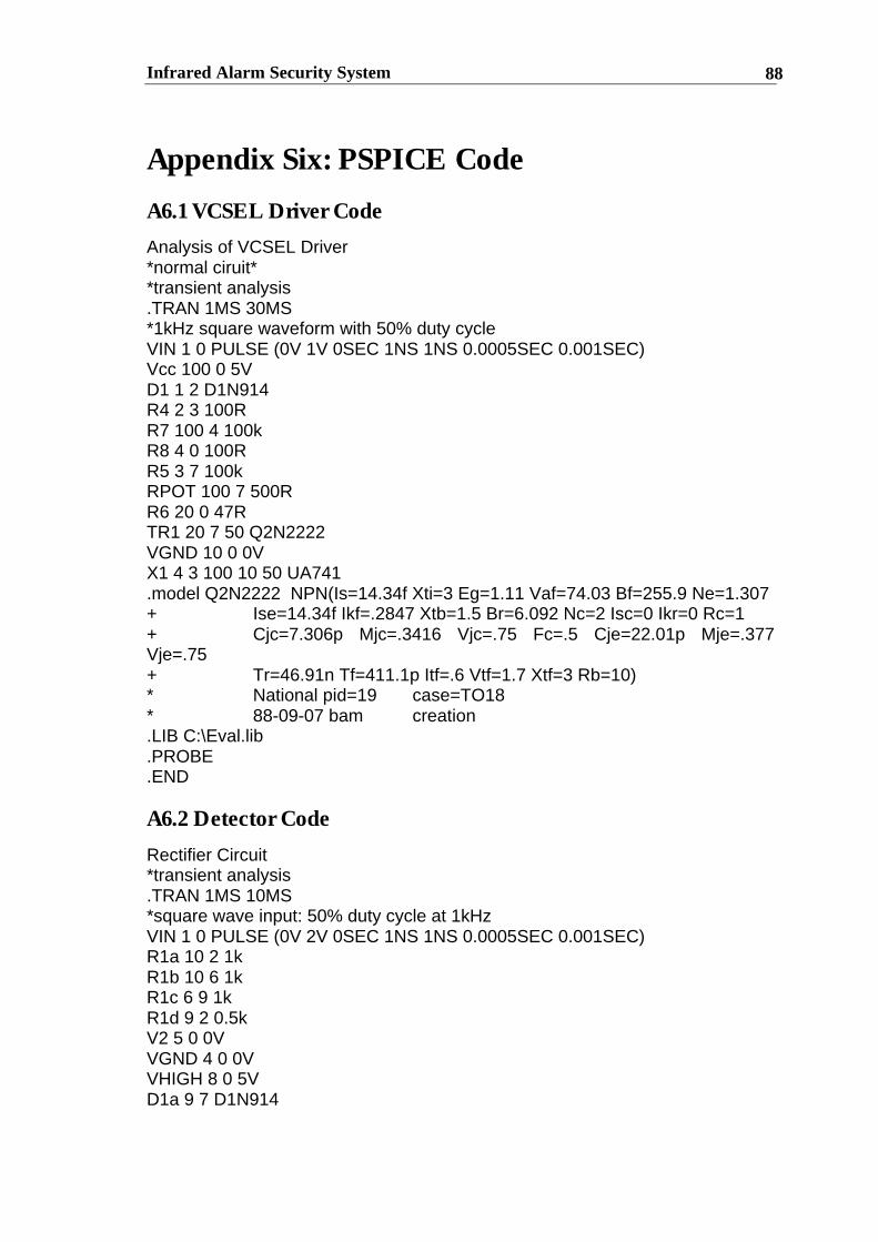
Infrared Alarm Security System 88
Appendix Six: PSPICE Code
A6.1 VCSEL Driver Code
Analysis of VCSEL Driver*normal ciruit**transient analysis.TRAN 1MS 30MS*1kHz square waveform with 50% duty cycleVIN 1 0 PULSE (0V 1V 0SEC 1NS 1NS 0.0005SEC 0.001SEC)Vcc 100 0 5VD1 1 2 D1N914R4 2 3 100RR7 100 4 100kR8 4 0 100RR5 3 7 100kRPOT 100 7 500RR6 20 0 47RTR1 20 7 50 Q2N2222VGND 10 0 0VX1 4 3 100 10 50 UA741.model Q2N2222 NPN(Is=14.34f Xti=3 Eg=1.11 Vaf=74.03 Bf=255.9 Ne=1.307+ Ise=14.34f Ikf=.2847 Xtb=1.5 Br=6.092 Nc=2 Isc=0 Ikr=0 Rc=1+ Cjc=7.306p Mjc=.3416 Vjc=.75 Fc=.5 Cje=22.01p Mje=.377Vje=.75+ Tr=46.91n Tf=411.1p Itf=.6 Vtf=1.7 Xtf=3 Rb=10)* National pid=19 case=TO18* 88-09-07 bam creation.LIB C:\Eval.lib.PROBE.END
A6.2 Detector Code
Rectifier Circuit*transient analysis.TRAN 1MS 10MS*square wave input: 50% duty cycle at 1kHzVIN 1 0 PULSE (0V 2V 0SEC 1NS 1NS 0.0005SEC 0.001SEC)R1a 10 2 1kR1b 10 6 1kR1c 6 9 1kR1d 9 2 0.5kV2 5 0 0VVGND 4 0 0VVHIGH 8 0 5VD1a 9 7 D1N914
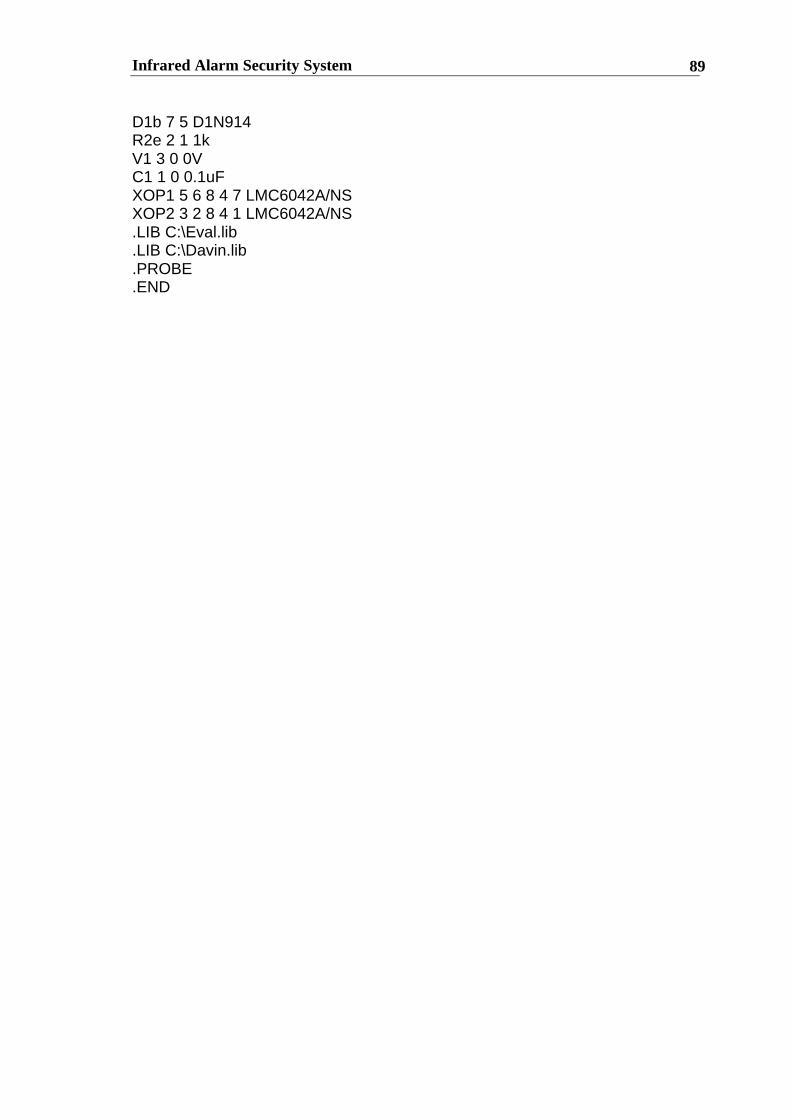
Infrared Alarm Security System 89
D1b 7 5 D1N914R2e 2 1 1kV1 3 0 0VC1 1 0 0.1uFXOP1 5 6 8 4 7 LMC6042A/NSXOP2 3 2 8 4 1 LMC6042A/NS.LIB C:\Eval.lib.LIB C:\Davin.lib.PROBE.END

Infrared Alarm Security System 90
Appendix Seven : Receiver Flow Chart Diagram
Turn Detector On
Is the receivedsignal high?
Yes
Rectify square wavesignal using a full-
wave rectifier
Limit rectified DCVoltage to 2V by
adjustingPotentiometer
Send 2V to inverterinput
Send low (0V) output ofInverter to input of Alerting
Apparatus
NoSend Low signal to
inverter input
Send High (4.5V) output ofInverter to input of Alerting
Apparatus

Infrared Alarm Security System 91
Appendix Eight: Accompanying Disk
This disk contains the counter that can be simulated in LogicWorks. The filename is
counter.cct.