informe de ensayo nº 9/le/ seguridad … · informe de ensayo nº 9/le/ seguridad elÉctrica...
TRANSCRIPT
Albert Marginet Morales Technical Manager
Electrical & Electronic Center LGAI Technological Center, S.A.
The results reported in this document relate only to the sample, product or item submitted to the Laboratory and described above, having been tested under the conditions established in this document. The reproduction of this document is only authorised if it’s made in its totality. The document has 51 pages from which 1 is appendix.
LGAI Technological Center,S.A. Inscrita en el Registro Mercantil de Barcelona, Tomo 35.803, Folio 1, Hoja Nº B-266.627 Inscripción 1ª.C.I.F. A-63207492
LGAI Technological Center, S.A. Campus de la UAB. Ronda de la Font del Carme, s/n. 08193 Bellaterra (Barcelona) T +34 93 567 20 00 / F +34 93 520 20 01 www.appluslaboratories.com
Expediente número 16/31702939
Página 1/51
INFORME DE ENSAYO SEGURIDAD ELÉCTRICA
Referencia del peticionario: HUMITAT-STOP S.L.
Dirección Vía Bellavista 80
08753 Pallejá Barcelona
Equipo ensayado: Sistema Micronizador
Marca: HUMITAT-STOP S.L. Modelo: DC-301
Número serie: 0301 N. ident. interna: 3868/1
Resultado:
Ha sido ensayado y es conforme con las especificaciones aplicadas* de la/s norma/s
* Ver especificaciones aplicadas en la página 4
Normas aplicadas:
UNE-EN 61010-1: 2011 Requisitos de seguridad de equipos eléctricos de medida, control y uso en laboratorio. Parte 1: requisitos generales
Características Nominales:
Tensión de alimentación (V) ....................... : 12 Vdc
Potencia asignada (W) ................................. : 1
Frecuencia (Hz) ........................................... : NA
Clase de equipo ........................................... : Clase III
Condición de operación ................................ : Continua
Fecha de emisión: Bellaterra, 03 de Mayo de 2016
Nº 9/LE/894
LGAI Technological Center, S.A.
UNE-EN 61010-1: 2011
Test report Nº: 16/31702939 Page 2 of 51
UNE-EN 61010-1: 2011
“REQUISITOS DE SEGURIDAD DE EQUIPOS ELÉCTRICOS DE MEDIDA, CONTROL Y USO EN
LABORATORIO”
PARTE 1: REQUISITOS GENERALES
Expediente número ........................ : 16/31702939
Fecha de recepción ........................ : 26/04/2016
Fecha de inicio de los ensayos ........ : 03/05/2016
Fecha de final de los ensayos ......... : 06/05/2016
Laboratorio de ensayos ................. : LGAI Technological Center, S.A.
Dirección ...................................... : Campus de la UAB. Ronda de la Font del Carme, s/n.
08193 Bellaterra (Barcelona)
Peticionario .................................. : HUMITAT-STOP S.L.
Dirección ...................................... : Vía Bellavista 80
08753 Pallejá
Barcelona
Descripción del material recibido ... : Sistema Micronizador
Fabricante .................................... : HUMITAT-STOP S.L.
Marca .......................................... : HUMITAT-STOP SL
Modelo ......................................... : DC-301
Número de serie ........................... : 0301
Número de identificación interna .... : 3868/1
UNE-EN 61010-1: 2011
Test report Nº: 16/31702939 Page 3 of 51
Características del equipo ensayado
Equipo sometido a ensayo ................. : Sistema Micronizador
Descripción de la función del equipo .. : El sistema emite un campo electromagnético al agua que entra en la vivienda el cual destruye los grumos en suspensión en el agua,
dejándolos de tamaño microscópico
Tensión asignada .............................. : 12 VDC (alimentado desde adaptador AC/DC externo)
Potencia asignada ............................. : 1 W
Corriente asignada ............................ : 2 A
Frecuencia asignada ......................... : Sin conexión directa a la red de alimentación
Instalación/categoría de sobretensión : II
Grado de polución ............................. : 2
Protección contra el choque eléctrico . : Equipo clase III
Características ambientales ............. : Estándar
Movilidad del equipo ....................... : fijo
Conexión a la red de alimentación ... : Sin conexión a la red de alimentación (alimentado desde adaptador
AC/DC externo)
Condiciones de operación ................. : continuo
Medidas (Largo x Ancho x profundo) ...................... : 130x95x65mm
Peso del equipo (g) ........................ : 500
Grado de protección según IEC 60529 ................... : IP65
Accesorios y partes amovibles incluidas en la evaluación ................ :
Sin accesorio o partes amovibles
Opciones ........................................ : NA
Condiciones ambientales durante la realización de los ensayos
Temperatura (ºC) ............................ :
Humedad relativa (%) ..................... :
UNE-EN 61010-1: 2011
Test report Nº: 16/31702939 Page 4 of 51
Información general del producto:
El sistema emite un campo electromagnético al agua que entra en la vivienda el cual destruye los grumos en
suspensión en el agua, dejándolos de tamaño microscópico
Apartados no evaluados:
5.4.1e). El análisis de riesgos no ha sido evaluado.
16. El análisis de riesgos no ha sido evaluado.
17. El análisis de riesgos no ha sido evaluado.
Condiciones de aceptabilidad:
- Se han considerado las siguientes características para la alimentación del equipo:
- Sin conexión directa a la red de alimentación
- Alimentado desde un adaptador AC/DC externo.
- La salida del alimentador externo se considera a muy baja tensión de seguridad de acuerdo a los
límites del apartado 6.3
- La salida del alimentador se considerada limitada en potencia de acuerdo al apartado 9.4.
- Todos los circuitos internos se considera que trabajan a muy baja tensión de seguridad según apartado 6.3 y están alimentados a potencia limitada según apartado 9.4.
- Se ha evaluado el equipo para una temperatura máxima de utilización de +60ºC
- Se ha evaluado el equipo para una altura máxima de funcionamiento inferior a 2000 metros.
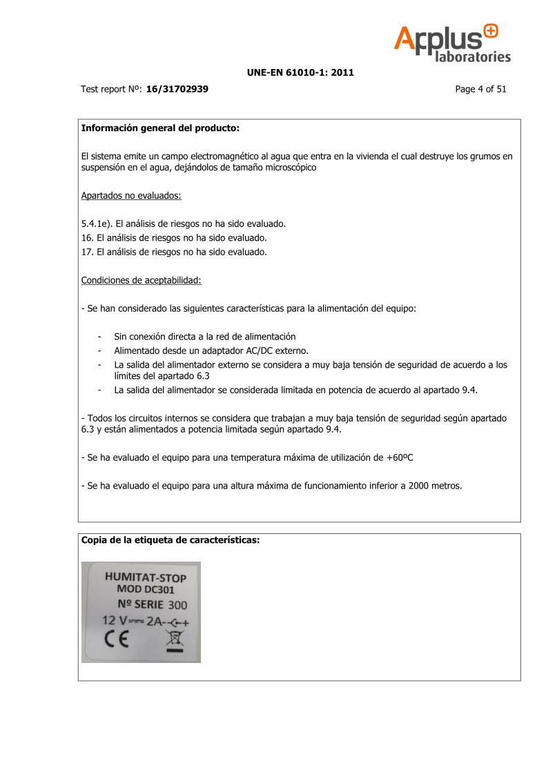
Copia de la etiqueta de características:
UNE-EN 61010-1: 2011
Test report Nº: 16/31702939 Page 5 of 51
Incertidumbres en las medidas
Las incertidumbres de medida han sido calculadas y están a disposición del cliente bajo petición.
Veredictos de los apartados:
El apartado no se aplica a la muestra ensayada ......... : N(o)A(plica)
La muestra cumple con los requisitos del apartado .... : P(asa)
La muestra no cumple con los requisitos del apartado : F(alla)
Los requisitos del apartado no han podido evaluarse . : N(o)T(esteado)
Observación sobre los resultados del apartado (Núm) : OBS(ervación)
Observaciones generales
Los resultados que se indican se refieren, exclusivamente, a la muestra, producto, o material entregado al Laboratorio, tal y como se indica en el apartado de material recibido, y ensayada en las condiciones indicadas
en la/s norma/s o procedimientos nombrados en el presente documento.
Garantía de Calidad de Servicio
Applus+, garantiza que este trabajo se ha realizado dentro de lo exigido por nuestro Sistema de Calidad y
Sostenibilidad, habiéndose cumplido las condiciones contractuales y la normativa legal.
En el marco de nuestro programa de mejora les agradecemos nos transmitan cualquier comentario que
consideren oportuno, dirigiéndose al responsable que firma este escrito, o bien, al Director de Calidad de Applus+, en la dirección: [email protected]
UNE-EN 61010-1: 2011
Test report Nº: 16/31702939 Page 6 of 51
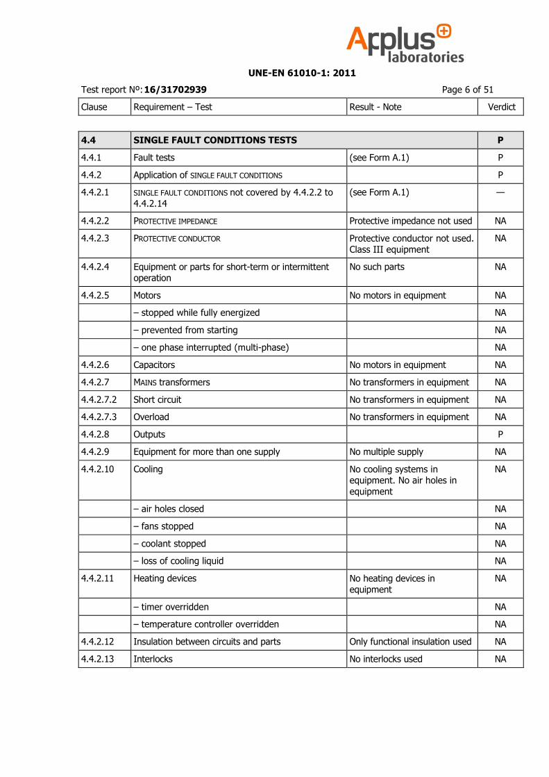
Clause Requirement – Test Result - Note Verdict
4.4 SINGLE FAULT CONDITIONS TESTS P
4.4.1 Fault tests (see Form A.1) P
4.4.2 Application of SINGLE FAULT CONDITIONS P
4.4.2.1 SINGLE FAULT CONDITIONS not covered by 4.4.2.2 to
4.4.2.14
(see Form A.1) —
4.4.2.2 PROTECTIVE IMPEDANCE Protective impedance not used NA
4.4.2.3 PROTECTIVE CONDUCTOR Protective conductor not used. Class III equipment
NA
4.4.2.4 Equipment or parts for short-term or intermittent operation
No such parts NA
4.4.2.5 Motors No motors in equipment NA
– stopped while fully energized NA
– prevented from starting NA
– one phase interrupted (multi-phase) NA
4.4.2.6 Capacitors No motors in equipment NA
4.4.2.7 MAINS transformers No transformers in equipment NA
4.4.2.7.2 Short circuit No transformers in equipment NA
4.4.2.7.3 Overload No transformers in equipment NA
4.4.2.8 Outputs P
4.4.2.9 Equipment for more than one supply No multiple supply NA
4.4.2.10 Cooling No cooling systems in equipment. No air holes in
equipment
NA
– air holes closed NA
– fans stopped NA
– coolant stopped NA
– loss of cooling liquid NA
4.4.2.11 Heating devices No heating devices in equipment
NA
– timer overridden NA
– temperature controller overridden NA
4.4.2.12 Insulation between circuits and parts Only functional insulation used NA
4.4.2.13 Interlocks No interlocks used NA
UNE-EN 61010-1: 2011
Test report Nº: 16/31702939 Page 7 of 51
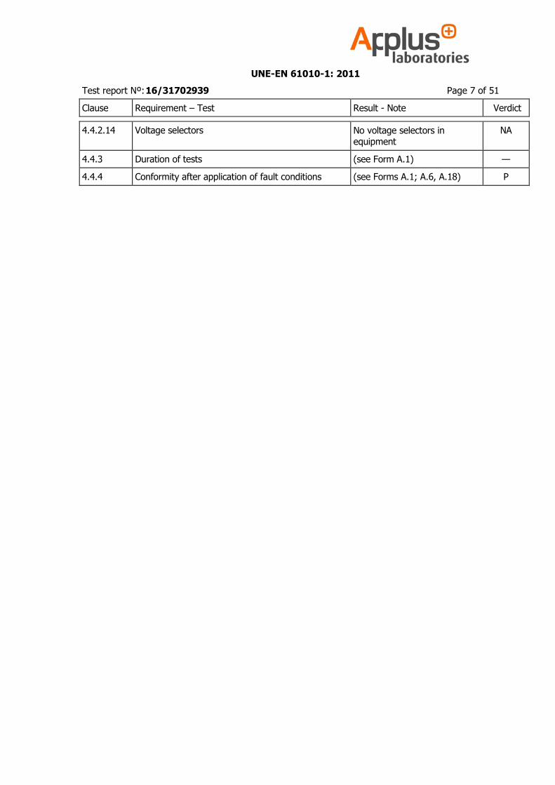
Clause Requirement – Test Result - Note Verdict
4.4.2.14 Voltage selectors No voltage selectors in equipment
NA
4.4.3 Duration of tests (see Form A.1) —
4.4.4 Conformity after application of fault conditions (see Forms A.1; A.6, A.18) P
UNE-EN 61010-1: 2011
Test report Nº: 16/31702939 Page 8 of 51
UNE - EN 61010-1
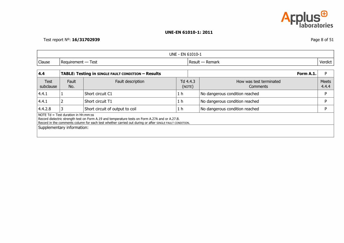
Clause Requirement — Test Result — Remark Verdict
4.4 TABLE: Testing in SINGLE FAULT CONDITION – Results Form A.1. P
Test
subclause
Fault
No.
Fault description Td 4.4.3
(NOTE)
How was test terminated
Comments
Meets
4.4.4
4.4.1 1 Short circuit C1 1 h No dangerous condition reached P
4.4.1 2 Short circuit T1 1 h No dangerous condition reached P
4.4.2.8 3 Short circuit of output to coil 1 h No dangerous condition reached P
NOTE Td = Test duration in hh:mm:ss Record dielectric strength test on Form A.19 and temperature tests on Form A.27A and or A.27.B. Record in the comments column for each test whether carried out during or after SINGLE FAULT CONDITION.
Supplementary information:
UNE-EN 61010-1: 2011
Test report Nº: 16/31702939 Page 9 of 51
Clause Requirement – Test Result - Note Verdict
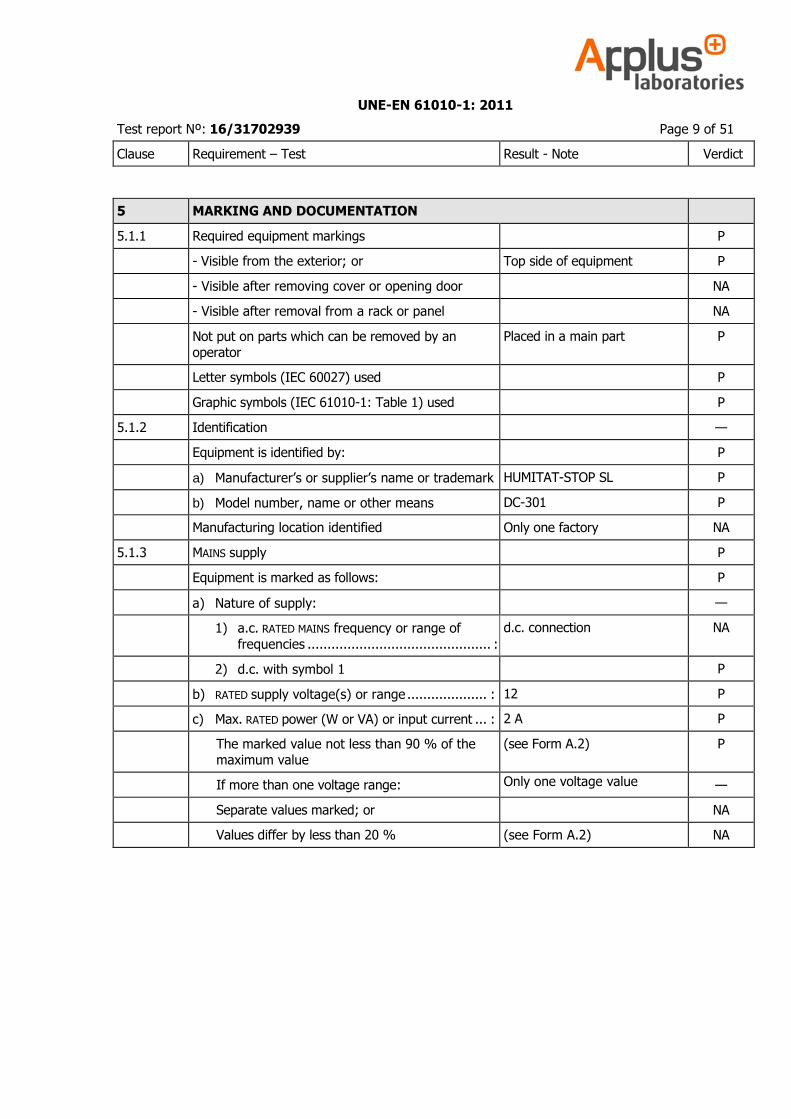
5 MARKING AND DOCUMENTATION
5.1.1 Required equipment markings P
- Visible from the exterior; or Top side of equipment P
- Visible after removing cover or opening door NA
- Visible after removal from a rack or panel NA
Not put on parts which can be removed by an operator
Placed in a main part P
Letter symbols (IEC 60027) used P
Graphic symbols (IEC 61010-1: Table 1) used P
5.1.2 Identification —
Equipment is identified by: P
a) Manufacturer’s or supplier’s name or trademark HUMITAT-STOP SL P
b) Model number, name or other means DC-301 P
Manufacturing location identified Only one factory NA
5.1.3 MAINS supply P
Equipment is marked as follows: P
a) Nature of supply: —
1) a.c. RATED MAINS frequency or range of
frequencies .............................................. :
d.c. connection NA
2) d.c. with symbol 1 P
b) RATED supply voltage(s) or range .................... : 12 P
c) Max. RATED power (W or VA) or input current ... : 2 A P
The marked value not less than 90 % of the maximum value
(see Form A.2) P
If more than one voltage range: Only one voltage value —
Separate values marked; or NA
Values differ by less than 20 % (see Form A.2) NA
UNE-EN 61010-1: 2011
Test report Nº: 16/31702939 Page 10 of 51
Clause Requirement – Test Result - Note Verdict
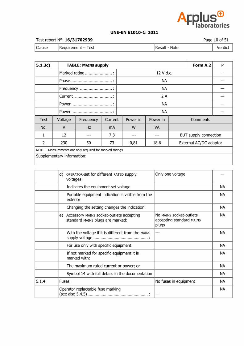
5.1.3c) TABLE: MAINS supply Form A.2 P
Marked rating ...................... : 12 V d.c. —
Phase .................................. : NA —
Frequency .......................... : NA —
Current .............................. : 2 A —
Power ................................ : NA —
Power ................................ : NA —
Test Voltage Frequency Current Power in Power in Comments
No. V Hz mA W VA
1 12 --- 7,3 --- --- EUT supply connection
2 230 50 73 0,81 18,6 External AC/DC adaptor
NOTE – Measurements are only required for marked ratings
Supplementary information:
d) OPERATOR-set for different RATED supply
voltages:
Only one voltage —
Indicates the equipment set voltage NA
Portable equipment indication is visible from the exterior
NA
Changing the setting changes the indication NA
e) Accessory MAINS socket-outlets accepting
standard MAINS plugs are marked:
No MAINS socket-outlets accepting standard MAINS
plugs
NA
With the voltage if it is different from the MAINS supply voltage .............................................. :
--- NA
For use only with specific equipment NA
If not marked for specific equipment it is marked with:
NA
The maximum rated current or power; or NA
Symbol 14 with full details in the documentation NA
5.1.4 Fuses No fuses in equipment NA
Operator replaceable fuse marking (see also 5.4.5) ................................................... : ---
NA
UNE-EN 61010-1: 2011
Test report Nº: 16/31702939 Page 11 of 51
Clause Requirement – Test Result - Note Verdict
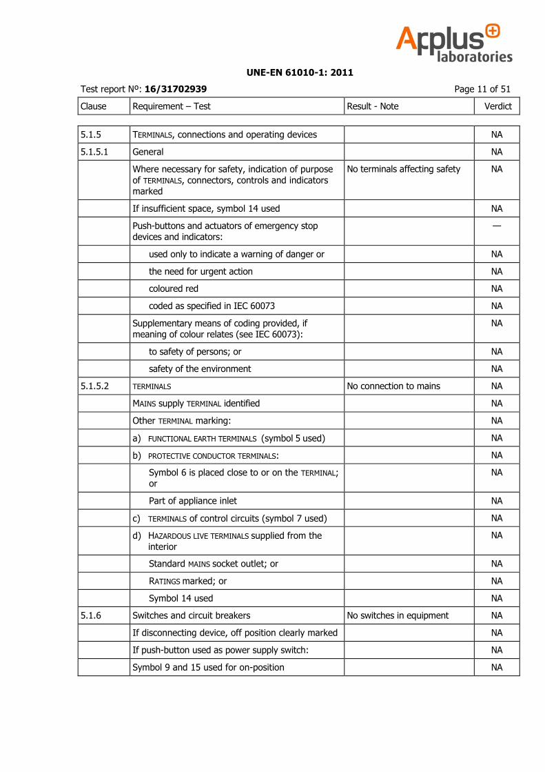
5.1.5 TERMINALS, connections and operating devices NA
5.1.5.1 General NA
Where necessary for safety, indication of purpose
of TERMINALS, connectors, controls and indicators marked
No terminals affecting safety NA
If insufficient space, symbol 14 used NA
Push-buttons and actuators of emergency stop devices and indicators:
—
used only to indicate a warning of danger or NA
the need for urgent action NA
coloured red NA
coded as specified in IEC 60073 NA
Supplementary means of coding provided, if meaning of colour relates (see IEC 60073):
NA
to safety of persons; or NA
safety of the environment NA
5.1.5.2 TERMINALS No connection to mains NA
MAINS supply TERMINAL identified NA
Other TERMINAL marking: NA
a) FUNCTIONAL EARTH TERMINALS (symbol 5 used) NA
b) PROTECTIVE CONDUCTOR TERMINALS: NA
Symbol 6 is placed close to or on the TERMINAL; or
NA
Part of appliance inlet NA
c) TERMINALS of control circuits (symbol 7 used) NA
d) HAZARDOUS LIVE TERMINALS supplied from the
interior
NA
Standard MAINS socket outlet; or NA
RATINGS marked; or NA
Symbol 14 used NA
5.1.6 Switches and circuit breakers No switches in equipment NA
If disconnecting device, off position clearly marked NA
If push-button used as power supply switch: NA
Symbol 9 and 15 used for on-position NA
UNE-EN 61010-1: 2011
Test report Nº: 16/31702939 Page 12 of 51
Clause Requirement – Test Result - Note Verdict
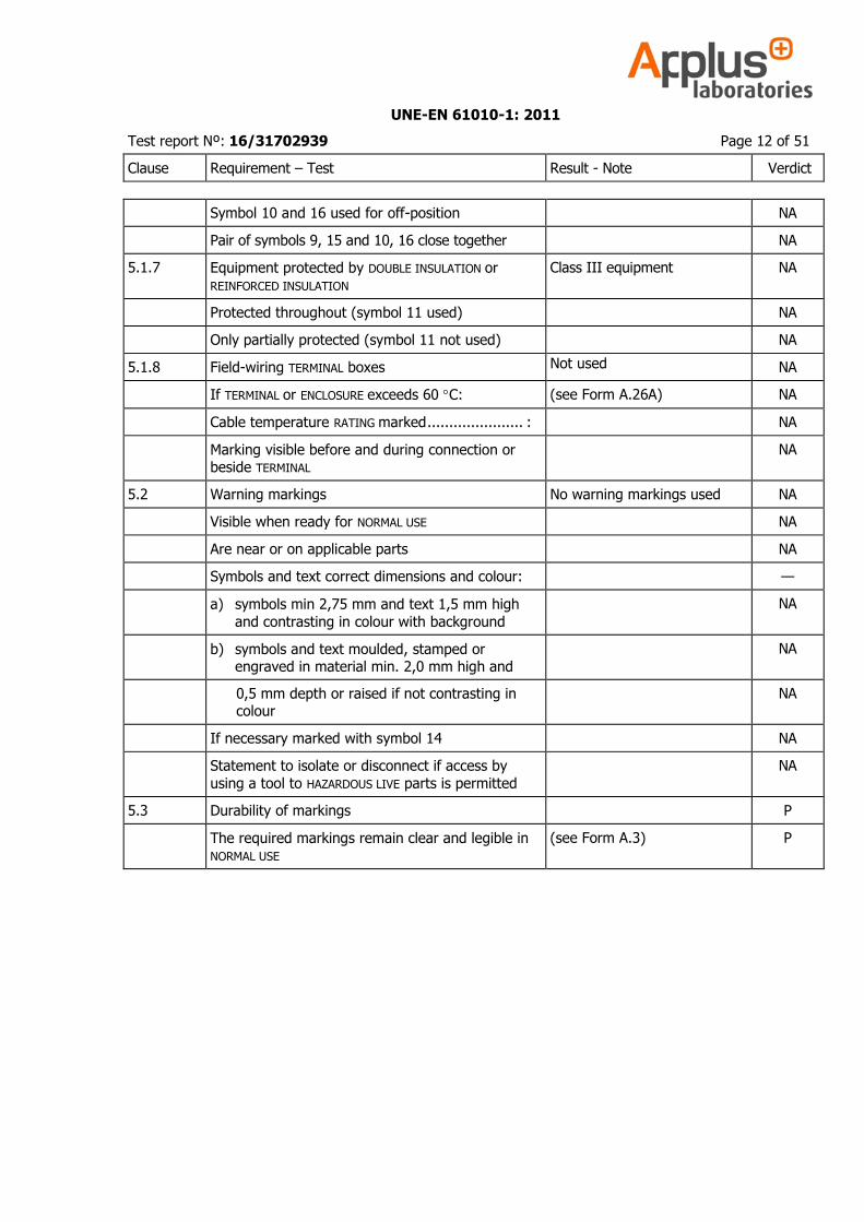
Symbol 10 and 16 used for off-position NA
Pair of symbols 9, 15 and 10, 16 close together NA
5.1.7 Equipment protected by DOUBLE INSULATION or
REINFORCED INSULATION
Class III equipment NA
Protected throughout (symbol 11 used) NA
Only partially protected (symbol 11 not used) NA
5.1.8 Field-wiring TERMINAL boxes Not used NA
If TERMINAL or ENCLOSURE exceeds 60 C: (see Form A.26A) NA
Cable temperature RATING marked ...................... : NA
Marking visible before and during connection or beside TERMINAL
NA
5.2 Warning markings No warning markings used NA
Visible when ready for NORMAL USE NA
Are near or on applicable parts NA
Symbols and text correct dimensions and colour: —
a) symbols min 2,75 mm and text 1,5 mm high
and contrasting in colour with background
NA
b) symbols and text moulded, stamped or engraved in material min. 2,0 mm high and
NA
0,5 mm depth or raised if not contrasting in colour
NA
If necessary marked with symbol 14 NA
Statement to isolate or disconnect if access by
using a tool to HAZARDOUS LIVE parts is permitted
NA
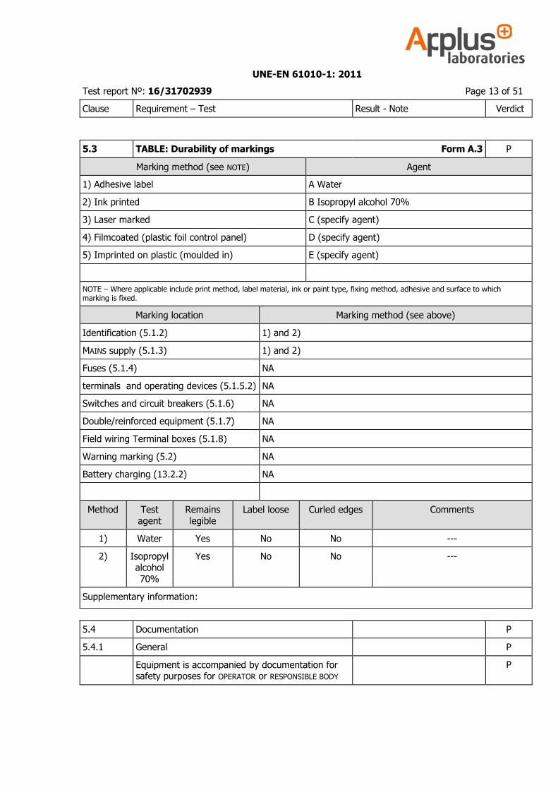
5.3 Durability of markings P
The required markings remain clear and legible in NORMAL USE
(see Form A.3) P
UNE-EN 61010-1: 2011
Test report Nº: 16/31702939 Page 13 of 51
Clause Requirement – Test Result - Note Verdict
5.3 TABLE: Durability of markings Form A.3 P
Marking method (see NOTE) Agent
1) Adhesive label A Water
2) Ink printed B Isopropyl alcohol 70%
3) Laser marked C (specify agent)
4) Filmcoated (plastic foil control panel) D (specify agent)
5) Imprinted on plastic (moulded in) E (specify agent)
NOTE – Where applicable include print method, label material, ink or paint type, fixing method, adhesive and surface to which marking is fixed.
Marking location Marking method (see above)
Identification (5.1.2) 1) and 2)
MAINS supply (5.1.3) 1) and 2)
Fuses (5.1.4) NA
terminals and operating devices (5.1.5.2) NA
Switches and circuit breakers (5.1.6) NA
Double/reinforced equipment (5.1.7) NA
Field wiring Terminal boxes (5.1.8) NA
Warning marking (5.2) NA
Battery charging (13.2.2) NA
Method Test
agent
Remains
legible
Label loose Curled edges Comments
1) Water Yes No No ---
2) Isopropyl alcohol
70%
Yes No No ---
Supplementary information:
5.4 Documentation P
5.4.1 General P
Equipment is accompanied by documentation for safety purposes for OPERATOR or RESPONSIBLE BODY
P
UNE-EN 61010-1: 2011
Test report Nº: 16/31702939 Page 14 of 51
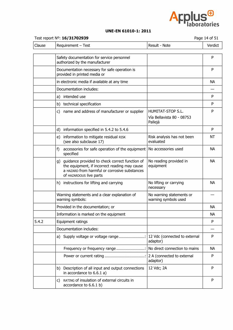
Clause Requirement – Test Result - Note Verdict
Safety documentation for service personnel authorized by the manufacturer
P
Documentation necessary for safe operation is provided in printed media or
P
in electronic media if available at any time NA
Documentation includes: —
a) intended use P
b) technical specification P
c) name and address of manufacturer or supplier HUMITAT-STOP S.L.
Vía Bellavista 80 - 08753 Pallejá
P
d) information specified in 5.4.2 to 5.4.6 P
e) information to mitigate residual RISK
(see also subclause 17)
Risk analysis has not been evaluated
NT
f) accessories for safe operation of the equipment specified
No accessories used NA
g) guidance provided to check correct function of
the equipment, if incorrect reading may cause a HAZARD from harmful or corrosive substances
of HAZARDOUS live parts
No reading provided in equipment
NA
h) instructions for lifting and carrying No lifting or carrying necessary
NA
Warning statements and a clear explanation of warning symbols:
No warning statements or warning symbols used
—
Provided in the documentation; or NA
Information is marked on the equipment NA
5.4.2 Equipment ratings P
Documentation includes: —
a) Supply voltage or voltage range ...................... : 12 Vdc (connected to external adaptor)
P
Frequency or frequency range ........................ : No direct connection to mains NA
Power or current rating .................................. : 2 A (connected to external adaptor)
P
b) Description of all input and output connections in accordance to 6.6.1 a)
12 Vdc; 2A P
c) RATING of insulation of external circuits in
accordance to 6.6.1 b)
P
UNE-EN 61010-1: 2011
Test report Nº: 16/31702939 Page 15 of 51
Clause Requirement – Test Result - Note Verdict
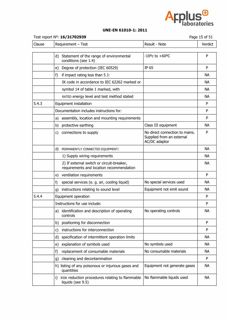
d) Statement of the range of environmental conditions (see 1.4)
-10ºc to +60ºC P
e) Degree of protection (IEC 60529) IP 65 P
f) if impact rating less than 5 J: NA
IK code in accordance to IEC 62262 marked or NA
symbol 14 of table 1 marked, with NA
RATED energy level and test method stated NA
5.4.3 Equipment installation P
Documentation includes instructions for: P
a) assembly, location and mounting requirements P
b) protective earthing Class III equipment NA
c) connections to supply No direct connection to mains. Supplied from an external AC/DC adaptor
P
d) PERMANENTLY CONNECTED EQUIPMENT: NA
1) Supply wiring requirements NA
2) If external switch or circuit-breaker,
requirements and location recommendation
NA
e) ventilation requirements P
f) special services (e. g. air, cooling liquid) No special services used NA
g) instructions relating to sound level Equipment not emit sound NA
5.4.4 Equipment operation P
Instructions for use include: P
a) identification and description of operating
controls
No operating controls NA
b) positioning for disconnection P
c) instructions for interconnection P
d) specification of intermittent operation limits NA
e) explanation of symbols used No symbols used NA
f) replacement of consumable materials No consumable materials NA
g) cleaning and decontamination P
h) listing of any poisonous or injurious gases and
quantities
Equipment not generate gases NA
i) RISK reduction procedures relating to flammable liquids (see 9.5)
No flammable liquids used NA
UNE-EN 61010-1: 2011
Test report Nº: 16/31702939 Page 16 of 51
Clause Requirement – Test Result - Note Verdict
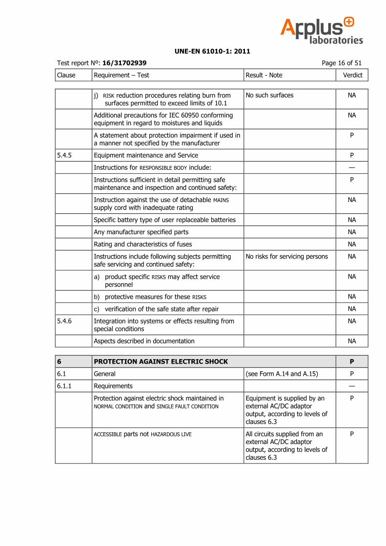
j) RISK reduction procedures relating burn from surfaces permitted to exceed limits of 10.1
No such surfaces NA
Additional precautions for IEC 60950 conforming equipment in regard to moistures and liquids
NA
A statement about protection impairment if used in a manner not specified by the manufacturer
P
5.4.5 Equipment maintenance and Service P
Instructions for RESPONSIBLE BODY include: —
Instructions sufficient in detail permitting safe maintenance and inspection and continued safety:
P
Instruction against the use of detachable MAINS supply cord with inadequate rating
NA
Specific battery type of user replaceable batteries NA
Any manufacturer specified parts NA
Rating and characteristics of fuses NA
Instructions include following subjects permitting safe servicing and continued safety:
No risks for servicing persons NA
a) product specific RISKS may affect service personnel
NA
b) protective measures for these RISKS NA
c) verification of the safe state after repair NA
5.4.6 Integration into systems or effects resulting from special conditions
NA
Aspects described in documentation NA
6 PROTECTION AGAINST ELECTRIC SHOCK P
6.1 General (see Form A.14 and A.15) P
6.1.1 Requirements —
Protection against electric shock maintained in NORMAL CONDITION and SINGLE FAULT CONDITION
Equipment is supplied by an external AC/DC adaptor
output, according to levels of clauses 6.3
P
ACCESSIBLE parts not HAZARDOUS LIVE All circuits supplied from an external AC/DC adaptor output, according to levels of
clauses 6.3
P
UNE-EN 61010-1: 2011
Test report Nº: 16/31702939 Page 17 of 51
Clause Requirement – Test Result - Note Verdict
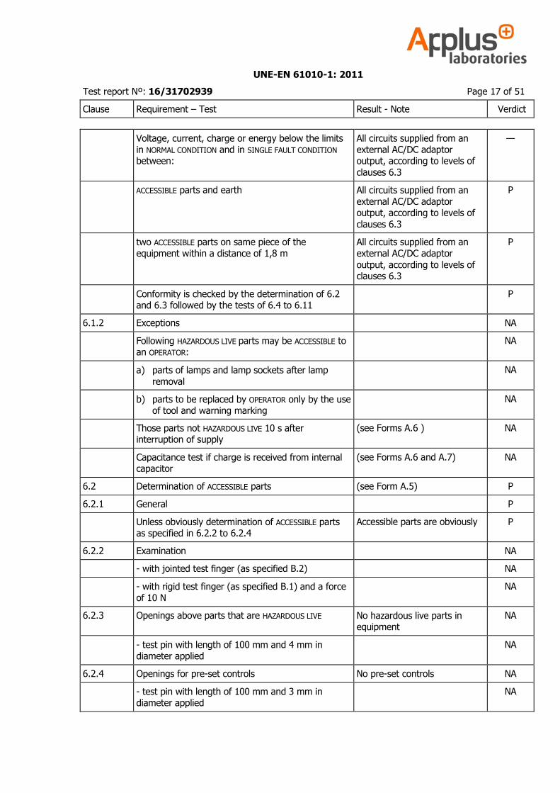
Voltage, current, charge or energy below the limits in NORMAL CONDITION and in SINGLE FAULT CONDITION
between:
All circuits supplied from an external AC/DC adaptor output, according to levels of
clauses 6.3
—
ACCESSIBLE parts and earth All circuits supplied from an
external AC/DC adaptor output, according to levels of
clauses 6.3
P
two ACCESSIBLE parts on same piece of the equipment within a distance of 1,8 m
All circuits supplied from an external AC/DC adaptor
output, according to levels of clauses 6.3
P
Conformity is checked by the determination of 6.2 and 6.3 followed by the tests of 6.4 to 6.11
P
6.1.2 Exceptions NA
Following HAZARDOUS LIVE parts may be ACCESSIBLE to an OPERATOR:
NA
a) parts of lamps and lamp sockets after lamp
removal
NA
b) parts to be replaced by OPERATOR only by the use of tool and warning marking
NA
Those parts not HAZARDOUS LIVE 10 s after interruption of supply
(see Forms A.6 ) NA
Capacitance test if charge is received from internal capacitor
(see Forms A.6 and A.7) NA
6.2 Determination of ACCESSIBLE parts (see Form A.5) P
6.2.1 General P
Unless obviously determination of ACCESSIBLE parts as specified in 6.2.2 to 6.2.4
Accessible parts are obviously P
6.2.2 Examination NA
- with jointed test finger (as specified B.2) NA
- with rigid test finger (as specified B.1) and a force of 10 N
NA
6.2.3 Openings above parts that are HAZARDOUS LIVE No hazardous live parts in equipment
NA
- test pin with length of 100 mm and 4 mm in diameter applied
NA
6.2.4 Openings for pre-set controls No pre-set controls NA
- test pin with length of 100 mm and 3 mm in diameter applied
NA
UNE-EN 61010-1: 2011
Test report Nº: 16/31702939 Page 18 of 51
Clause Requirement – Test Result - Note Verdict
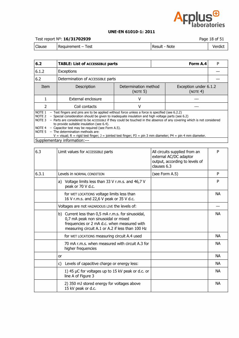
6.2 TABLE: List of ACCESSIBLE parts Form A.4 P
6.1.2 Exceptions —
6.2 Determination of ACCESSIBLE parts —
Item Description Determination method
(NOTE 5)
Exception under 6.1.2
(NOTE 4)
1 External enclosure V ---
2 Coil contacts V ---
NOTE 1 – Test fingers and pins are to be applied without force unless a force is specified (see 6.2.2) NOTE 2 – Special consideration should be given to inadequate insulation and high voltage parts (see 6.2) NOTE 3 – Parts are considered to be ACCESSIBLE if they could be touched in the absence of any covering which is not considered to provide suitable insulation (see 6.4). NOTE 4 – Capacitor test may be required (see Form A.5). NOTE 5 – The determination methods are: V = visual; R = rigid test finger; J = jointed test finger; P3 = pin 3 mm diameter; P4 = pin 4 mm diameter.
Supplementary information:---
6.3 Limit values for ACCESSIBLE parts All circuits supplied from an external AC/DC adaptor
output, according to levels of clauses 6.3
P
6.3.1 Levels in NORMAL CONDITION (see Form A.5) P
a) Voltage limits less than 33 V r.m.s. and 46,7 V peak or 70 V d.c.
P
for WET LOCATIONS voltage limits less than
16 V r.m.s. and 22,6 V peak or 35 V d.c.
NA
Voltages are not HAZARDOUS LIVE the levels of: —
b) Current less than 0,5 mA r.m.s. for sinusoidal,
0,7 mA peak non sinusoidal or mixed frequencies or 2 mA d.c. when measured with
measuring circuit A.1 or A.2 if less than 100 Hz
NA
for WET LOCATIONS measuring circuit A.4 used NA
70 mA r.m.s. when measured with circuit A.3 for higher frequencies
NA
or NA
c) Levels of capacitive charge or energy less: NA
1) 45 µC for voltages up to 15 kV peak or d.c. or line A of Figure 3
NA
2) 350 mJ stored energy for voltages above
15 kV peak or d.c.
NA
UNE-EN 61010-1: 2011
Test report Nº: 16/31702939 Page 19 of 51
Clause Requirement – Test Result - Note Verdict
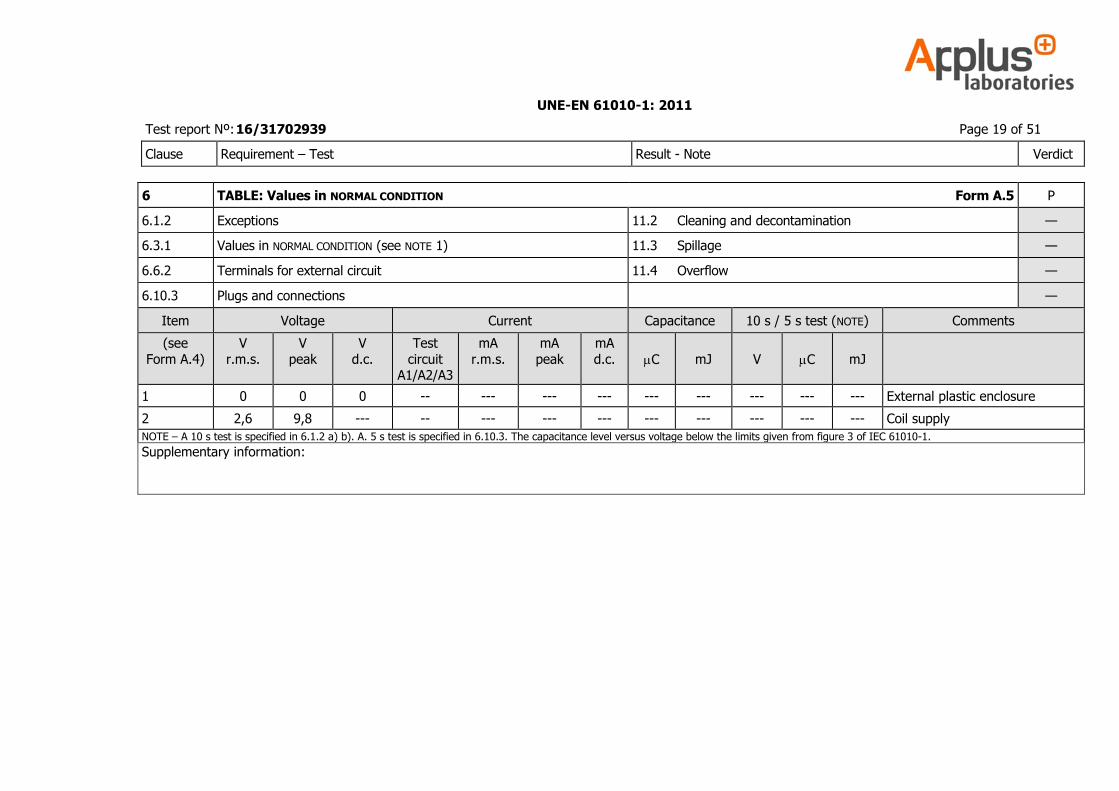
6 TABLE: Values in NORMAL CONDITION Form A.5 P
6.1.2 Exceptions 11.2 Cleaning and decontamination —
6.3.1 Values in NORMAL CONDITION (see NOTE 1) 11.3 Spillage —
6.6.2 Terminals for external circuit 11.4 Overflow —
6.10.3 Plugs and connections —
Item Voltage Current Capacitance 10 s / 5 s test (NOTE) Comments
(see
Form A.4)
V
r.m.s.
V
peak
V
d.c.
Test
circuit A1/A2/A3
mA
r.m.s.
mA
peak
mA
d.c.
C
mJ
V
C
mJ
1 0 0 0 -- --- --- --- --- --- --- --- --- External plastic enclosure
2 2,6 9,8 --- -- --- --- --- --- --- --- --- --- Coil supply
NOTE – A 10 s test is specified in 6.1.2 a) b). A. 5 s test is specified in 6.10.3. The capacitance level versus voltage below the limits given from figure 3 of IEC 61010-1.
Supplementary information:
UNE-EN 61010-1: 2011
Test report Nº: 16/31702939 Page 20 of 51
Clause Requirement – Test Result - Note Verdict
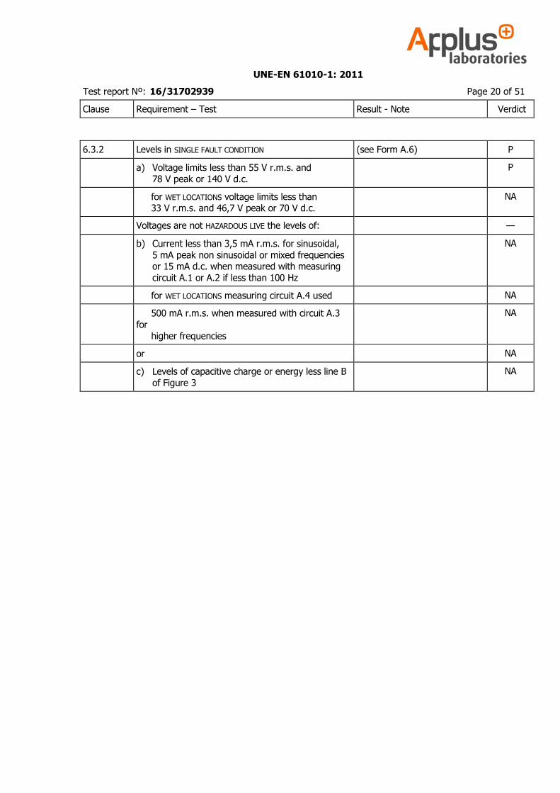
6.3.2 Levels in SINGLE FAULT CONDITION (see Form A.6) P
a) Voltage limits less than 55 V r.m.s. and
78 V peak or 140 V d.c.
P
for WET LOCATIONS voltage limits less than 33 V r.m.s. and 46,7 V peak or 70 V d.c.
NA
Voltages are not HAZARDOUS LIVE the levels of: —
b) Current less than 3,5 mA r.m.s. for sinusoidal,
5 mA peak non sinusoidal or mixed frequencies or 15 mA d.c. when measured with measuring
circuit A.1 or A.2 if less than 100 Hz
NA
for WET LOCATIONS measuring circuit A.4 used NA
500 mA r.m.s. when measured with circuit A.3
for
higher frequencies
NA
or NA
c) Levels of capacitive charge or energy less line B
of Figure 3
NA
UNE-EN 61010-1: 2011
Test report Nº: 16/31702939 Page 21 of 51
Clause Requirement – Test Result - Note Verdict
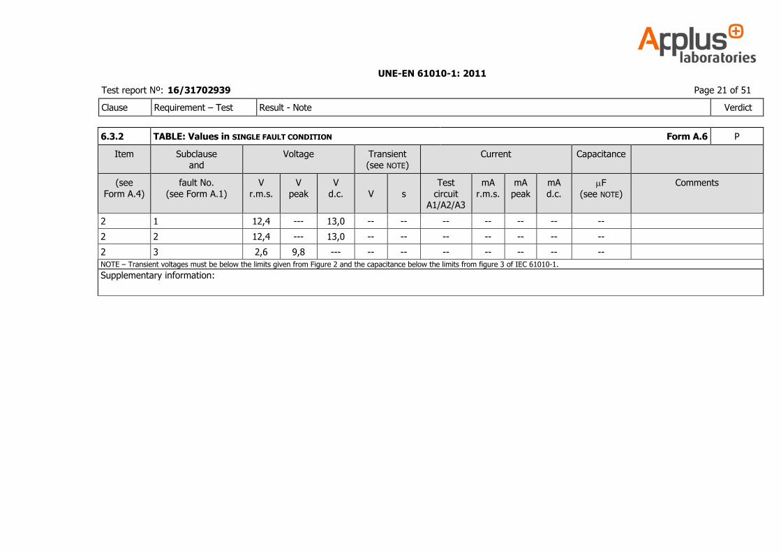
6.3.2 TABLE: Values in SINGLE FAULT CONDITION Form A.6 P
Item Subclause and
Voltage Transient (see NOTE)
Current Capacitance
(see
Form A.4)
fault No.
(see Form A.1)
V
r.m.s.
V
peak
V
d.c.
V
s
Test
circuit A1/A2/A3
mA
r.m.s.
mA
peak
mA
d.c. F
(see NOTE)
Comments
2 1 12,4 --- 13,0 -- -- -- -- -- -- --
2 2 12,4 --- 13,0 -- -- -- -- -- -- --
2 3 2,6 9,8 --- -- -- -- -- -- -- --
NOTE – Transient voltages must be below the limits given from Figure 2 and the capacitance below the limits from figure 3 of IEC 61010-1.
Supplementary information:
UNE-EN 61010-1: 2011
Test report Nº: 16/31702939 Page 22 of 51
Clause Requirement – Test Result - Note Verdict
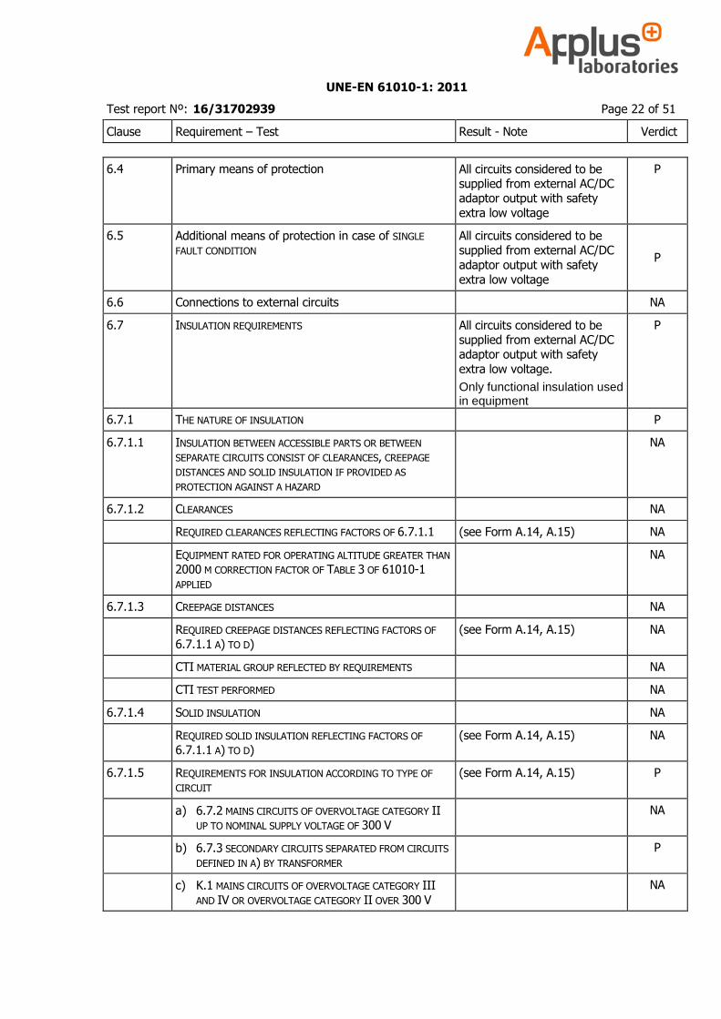
6.4 Primary means of protection All circuits considered to be supplied from external AC/DC adaptor output with safety
extra low voltage
P
6.5 Additional means of protection in case of SINGLE
FAULT CONDITION All circuits considered to be supplied from external AC/DC
adaptor output with safety
extra low voltage
P
6.6 Connections to external circuits NA
6.7 INSULATION REQUIREMENTS All circuits considered to be supplied from external AC/DC adaptor output with safety
extra low voltage.
Only functional insulation used in equipment
P
6.7.1 THE NATURE OF INSULATION P
6.7.1.1 INSULATION BETWEEN ACCESSIBLE PARTS OR BETWEEN
SEPARATE CIRCUITS CONSIST OF CLEARANCES, CREEPAGE
DISTANCES AND SOLID INSULATION IF PROVIDED AS
PROTECTION AGAINST A HAZARD
NA
6.7.1.2 CLEARANCES NA
REQUIRED CLEARANCES REFLECTING FACTORS OF 6.7.1.1 (see Form A.14, A.15) NA
EQUIPMENT RATED FOR OPERATING ALTITUDE GREATER THAN
2000 M CORRECTION FACTOR OF TABLE 3 OF 61010-1
APPLIED
NA
6.7.1.3 CREEPAGE DISTANCES NA
REQUIRED CREEPAGE DISTANCES REFLECTING FACTORS OF
6.7.1.1 A) TO D)
(see Form A.14, A.15) NA
CTI MATERIAL GROUP REFLECTED BY REQUIREMENTS NA
CTI TEST PERFORMED NA
6.7.1.4 SOLID INSULATION NA
REQUIRED SOLID INSULATION REFLECTING FACTORS OF 6.7.1.1 A) TO D)
(see Form A.14, A.15) NA
6.7.1.5 REQUIREMENTS FOR INSULATION ACCORDING TO TYPE OF
CIRCUIT
(see Form A.14, A.15) P
a) 6.7.2 MAINS CIRCUITS OF OVERVOLTAGE CATEGORY II UP TO NOMINAL SUPPLY VOLTAGE OF 300 V
NA
b) 6.7.3 SECONDARY CIRCUITS SEPARATED FROM CIRCUITS
DEFINED IN A) BY TRANSFORMER
P
c) K.1 MAINS CIRCUITS OF OVERVOLTAGE CATEGORY III
AND IV OR OVERVOLTAGE CATEGORY II OVER 300 V
NA
UNE-EN 61010-1: 2011
Test report Nº: 16/31702939 Page 23 of 51
Clause Requirement – Test Result - Note Verdict
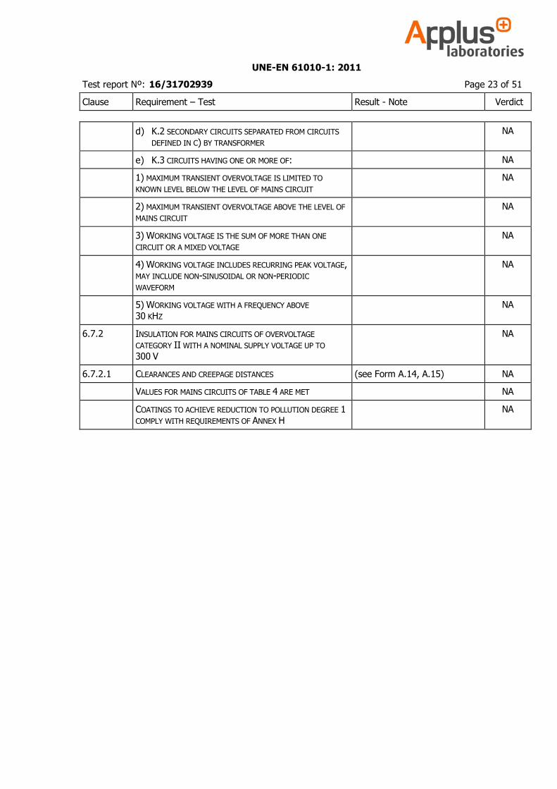
d) K.2 SECONDARY CIRCUITS SEPARATED FROM CIRCUITS
DEFINED IN C) BY TRANSFORMER
NA
e) K.3 CIRCUITS HAVING ONE OR MORE OF: NA
1) MAXIMUM TRANSIENT OVERVOLTAGE IS LIMITED TO
KNOWN LEVEL BELOW THE LEVEL OF MAINS CIRCUIT
NA
2) MAXIMUM TRANSIENT OVERVOLTAGE ABOVE THE LEVEL OF
MAINS CIRCUIT
NA
3) WORKING VOLTAGE IS THE SUM OF MORE THAN ONE
CIRCUIT OR A MIXED VOLTAGE
NA
4) WORKING VOLTAGE INCLUDES RECURRING PEAK VOLTAGE, MAY INCLUDE NON-SINUSOIDAL OR NON-PERIODIC
WAVEFORM
NA
5) WORKING VOLTAGE WITH A FREQUENCY ABOVE 30 KHZ
NA
6.7.2 INSULATION FOR MAINS CIRCUITS OF OVERVOLTAGE
CATEGORY II WITH A NOMINAL SUPPLY VOLTAGE UP TO 300 V
NA
6.7.2.1 CLEARANCES AND CREEPAGE DISTANCES (see Form A.14, A.15) NA
VALUES FOR MAINS CIRCUITS OF TABLE 4 ARE MET NA
COATINGS TO ACHIEVE REDUCTION TO POLLUTION DEGREE 1
COMPLY WITH REQUIREMENTS OF ANNEX H
NA
UNE-EN 61010-1: 2011
Test report Nº: 16/31702939 Page 24 of 51
Clause Requirement – Test Result - Note Verdict
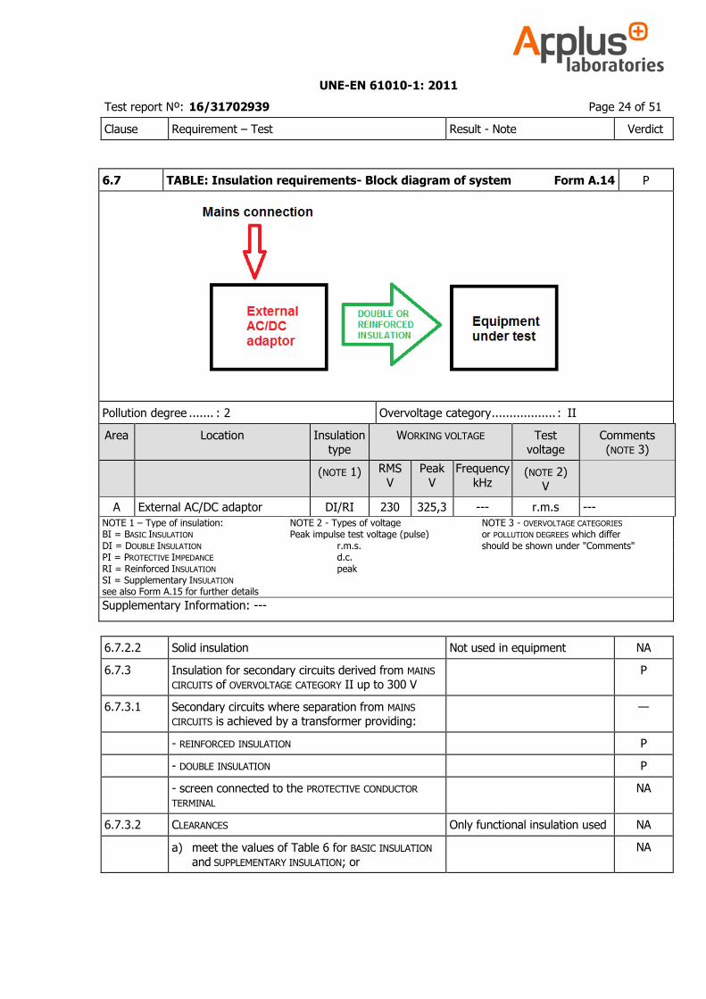
6.7 TABLE: Insulation requirements- Block diagram of system Form A.14 P
Pollution degree ....... : 2 Overvoltage category .................. : II
Area Location Insulation type
WORKING VOLTAGE Test voltage
Comments (NOTE 3)
(NOTE 1) RMS
V
Peak
V
Frequency
kHz (NOTE 2)
V
A External AC/DC adaptor DI/RI 230 325,3 --- r.m.s ---
NOTE 1 – Type of insulation: NOTE 2 - Types of voltage NOTE 3 - OVERVOLTAGE CATEGORIES BI = BASIC INSULATION Peak impulse test voltage (pulse) or POLLUTION DEGREES which differ DI = DOUBLE INSULATION r.m.s. should be shown under "Comments" PI = PROTECTIVE IMPEDANCE d.c. RI = Reinforced INSULATION peak SI = Supplementary INSULATION see also Form A.15 for further details
Supplementary Information: ---
6.7.2.2 Solid insulation Not used in equipment NA
6.7.3 Insulation for secondary circuits derived from MAINS CIRCUITS of OVERVOLTAGE CATEGORY II up to 300 V
P
6.7.3.1 Secondary circuits where separation from MAINS CIRCUITS is achieved by a transformer providing:
—
- REINFORCED INSULATION P
- DOUBLE INSULATION P
- screen connected to the PROTECTIVE CONDUCTOR TERMINAL
NA
6.7.3.2 CLEARANCES Only functional insulation used NA
a) meet the values of Table 6 for BASIC INSULATION
and SUPPLEMENTARY INSULATION; or
NA

UNE-EN 61010-1: 2011
Test report Nº: 16/31702939 Page 25 of 51
Clause Requirement – Test Result - Note Verdict
twice the values of Table 6 for REINFORCED INSULATION
NA
b) pass the voltage tests of 6.8 with values of
Table 6; with following adjustments:
(see Form A.18) NA
1) values for REINFORCED INSULATION are 1,6 times the values for BASIC INSULATION
NA
2) if operating altitude is greater than 2000 m values of CLEARANCES multiplied with factor of
Table 3
NA
3) minimum CLEARANCE is 0,2 mm for POLLUTION DEGREE 2 and 0,8 mm for POLLUTION DEGREE 3
NA
6.7.3.3 CREEPAGE DISTANCES Only functional insulation used NA
Based on WORKING VOLTAGE meets the values of Table 7 for BASIC and SUPPLEMENTARY INSULATION
NA
Values for REINFORCED INSULATION are twice the values of BASIC INSULATION
NA
Coatings to achieve reduction to POLLUTION DEGREE 1 comply with requirements of Annex H
NA
6.7.3.4 Solid insulation Not used in equipment NA
6.7.3.4.1 Withstands electrical and mechanical stresses in normal use and all RATED environmental conditions
of 1.4
NA
a) Equipment passed voltage test of 6.8.3.1 for 5 s
with VALUES of Table 6 for BASIC and SUPPLEMENTARY INSULATION
(see Form A.18) NA
values for REINFORCED INSULATION are 1,6 times the values of BASIC INSULATION
NA
b) if WORKING VOLTAGE exceeds 300 V, equipment passed voltage test of 6.8.3.1 for 1 min with a
test voltage of 1,5 times working voltage for BASIC or SUPPLEMENTARY INSULATION
(see Form A.18) NA
value for REINFORCED INSULATION are twice the WORKING VOLTAGE
NA
Complies as applicable: NA
1) ENCLOSURE or PROTECTIVE BARRIER of Clause 8 NA
2) moulded and potted parts requirements of
6.7.3.4.2
NA
3) inner layers of printed wiring boards requirements of 6.7.3.4.3
NA
4) thin-film insulation requirements of 6.7.3.4.4 NA

UNE-EN 61010-1: 2011
Test report Nº: 16/31702939 Page 26 of 51
Clause Requirement – Test Result - Note Verdict
6.7.3.4.2 Moulded and potted parts NA
Conductors between same two layers are separated
by applicable distances of Table 8
NA
6.7.3.4.3 Inner insulation layers of printed wiring boards NA
Separated by at least by applicable distances of Table 8 between same two layers
NA
REINFORCED INSULATION have adequate electric strength; one of following methods used:
NA
a) thickness at least applicable distance of Table 8 NA
b) insulation is assembled of minimum two
separate layers, each RATED for test voltage of
Table 6 for BASIC INSULATION
NA
c) insulation is assembled of min two separate
layers, where the combination is RATED for 1,6
times the test voltage of Table 6
NA
6.7.3.4.4 Thin-film insulation NA
Conductors between same two layers are separated by applicable CLEARANCES and CREEPAGE DISTANCE
of 6.7.3.2 and 6.7.3.3
NA
REINFORCED INSULATION have adequate electric strength; one of following methods used:
NA
a) thickness at least applicable distance of Table 8 NA
b) insulation is assembled of min two separate layers, each RATED for test voltage of Table 6 for
BASIC INSULATION
NA
c) insulation is assembled of min three separate layers, where the combination of two layers
passed voltage tests with 1,6 time values of Table 6:
NA
a.c. test of 6.8.3.1; or NA
d.c. test of 6.8.3.2 for circuits stressed only by d.c. voltages
NA
6.8 Procedure for dielectric strength tests NA
UNE-EN 61010-1: 2011
Test report Nº: 16/31702939 Page 27 of 51
Clause Requirement – Test Result - Note Verdict
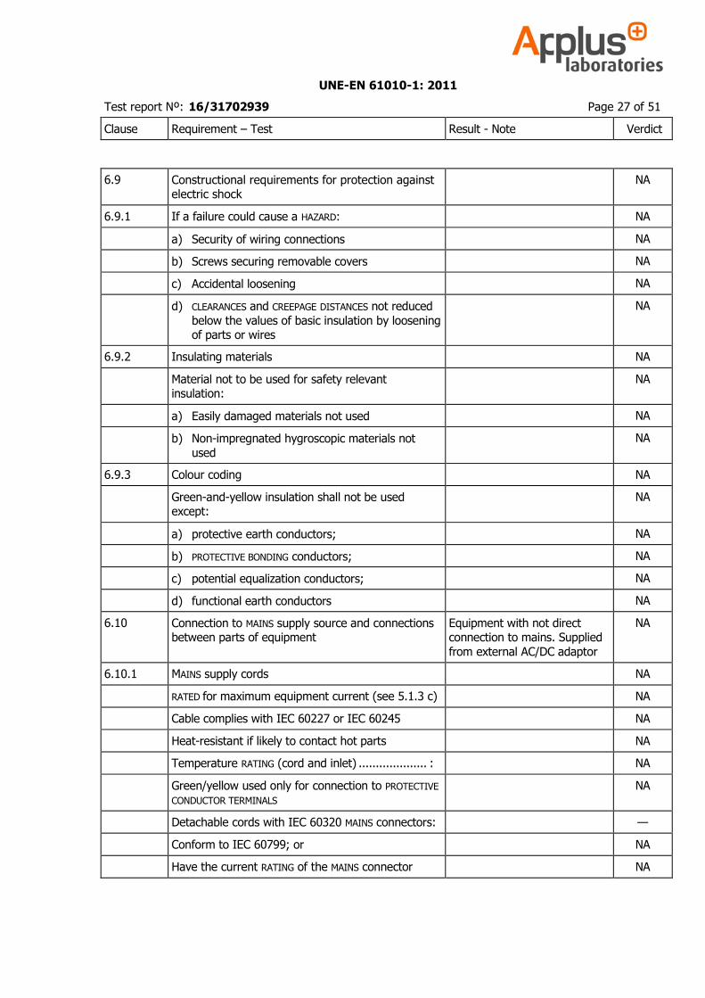
6.9 Constructional requirements for protection against electric shock
NA
6.9.1 If a failure could cause a HAZARD: NA
a) Security of wiring connections NA
b) Screws securing removable covers NA
c) Accidental loosening NA
d) CLEARANCES and CREEPAGE DISTANCES not reduced
below the values of basic insulation by loosening of parts or wires
NA
6.9.2 Insulating materials NA
Material not to be used for safety relevant insulation:
NA
a) Easily damaged materials not used NA
b) Non-impregnated hygroscopic materials not
used
NA
6.9.3 Colour coding NA
Green-and-yellow insulation shall not be used except:
NA
a) protective earth conductors; NA
b) PROTECTIVE BONDING conductors; NA
c) potential equalization conductors; NA
d) functional earth conductors NA
6.10 Connection to MAINS supply source and connections between parts of equipment
Equipment with not direct connection to mains. Supplied
from external AC/DC adaptor
NA
6.10.1 MAINS supply cords NA
RATED for maximum equipment current (see 5.1.3 c) NA
Cable complies with IEC 60227 or IEC 60245 NA
Heat-resistant if likely to contact hot parts NA
Temperature RATING (cord and inlet) .................... : NA
Green/yellow used only for connection to PROTECTIVE
CONDUCTOR TERMINALS
NA
Detachable cords with IEC 60320 MAINS connectors: —
Conform to IEC 60799; or NA
Have the current RATING of the MAINS connector NA
UNE-EN 61010-1: 2011
Test report Nº: 16/31702939 Page 28 of 51
Clause Requirement – Test Result - Note Verdict
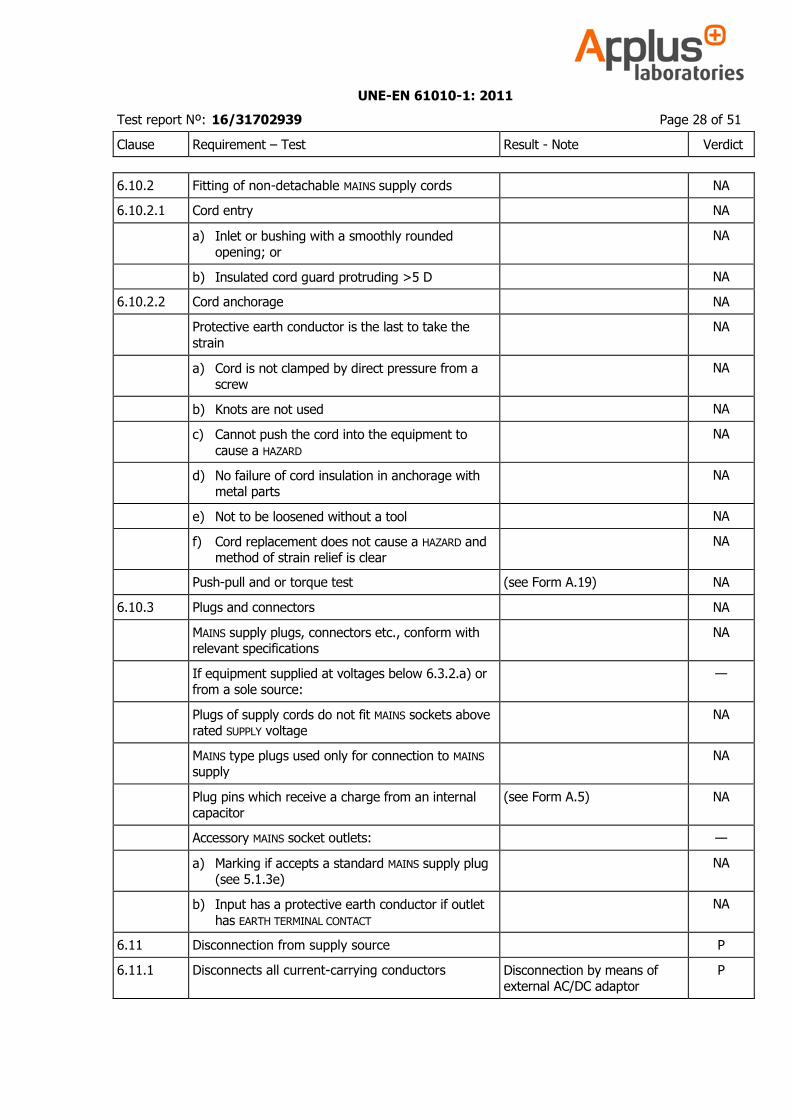
6.10.2 Fitting of non-detachable MAINS supply cords NA
6.10.2.1 Cord entry NA
a) Inlet or bushing with a smoothly rounded
opening; or
NA
b) Insulated cord guard protruding >5 D NA
6.10.2.2 Cord anchorage NA
Protective earth conductor is the last to take the
strain
NA
a) Cord is not clamped by direct pressure from a screw
NA
b) Knots are not used NA
c) Cannot push the cord into the equipment to
cause a HAZARD
NA
d) No failure of cord insulation in anchorage with metal parts
NA
e) Not to be loosened without a tool NA
f) Cord replacement does not cause a HAZARD and method of strain relief is clear
NA
Push-pull and or torque test (see Form A.19) NA
6.10.3 Plugs and connectors NA
MAINS supply plugs, connectors etc., conform with relevant specifications
NA
If equipment supplied at voltages below 6.3.2.a) or from a sole source:
—
Plugs of supply cords do not fit MAINS sockets above rated SUPPLY voltage
NA
MAINS type plugs used only for connection to MAINS supply
NA
Plug pins which receive a charge from an internal capacitor
(see Form A.5) NA
Accessory MAINS socket outlets: —
a) Marking if accepts a standard MAINS supply plug (see 5.1.3e)
NA
b) Input has a protective earth conductor if outlet
has EARTH TERMINAL CONTACT
NA
6.11 Disconnection from supply source P
6.11.1 Disconnects all current-carrying conductors Disconnection by means of external AC/DC adaptor
P
UNE-EN 61010-1: 2011
Test report Nº: 16/31702939 Page 29 of 51
Clause Requirement – Test Result - Note Verdict
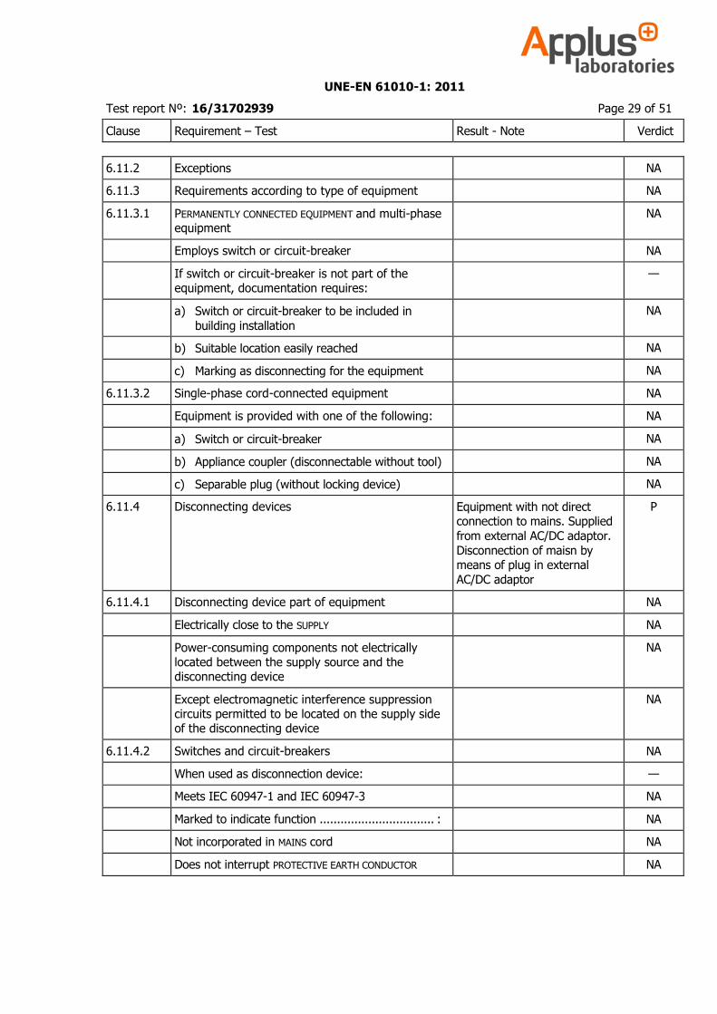
6.11.2 Exceptions NA
6.11.3 Requirements according to type of equipment NA
6.11.3.1 PERMANENTLY CONNECTED EQUIPMENT and multi-phase equipment
NA
Employs switch or circuit-breaker NA
If switch or circuit-breaker is not part of the equipment, documentation requires:
—
a) Switch or circuit-breaker to be included in
building installation
NA
b) Suitable location easily reached NA
c) Marking as disconnecting for the equipment NA
6.11.3.2 Single-phase cord-connected equipment NA
Equipment is provided with one of the following: NA
a) Switch or circuit-breaker NA
b) Appliance coupler (disconnectable without tool) NA
c) Separable plug (without locking device) NA
6.11.4 Disconnecting devices Equipment with not direct connection to mains. Supplied
from external AC/DC adaptor.
Disconnection of maisn by means of plug in external
AC/DC adaptor
P
6.11.4.1 Disconnecting device part of equipment NA
Electrically close to the SUPPLY NA
Power-consuming components not electrically located between the supply source and the disconnecting device
NA
Except electromagnetic interference suppression circuits permitted to be located on the supply side of the disconnecting device
NA
6.11.4.2 Switches and circuit-breakers NA
When used as disconnection device: —
Meets IEC 60947-1 and IEC 60947-3 NA
Marked to indicate function ................................. : NA
Not incorporated in MAINS cord NA
Does not interrupt PROTECTIVE EARTH CONDUCTOR NA
UNE-EN 61010-1: 2011
Test report Nº: 16/31702939 Page 30 of 51
Clause Requirement – Test Result - Note Verdict
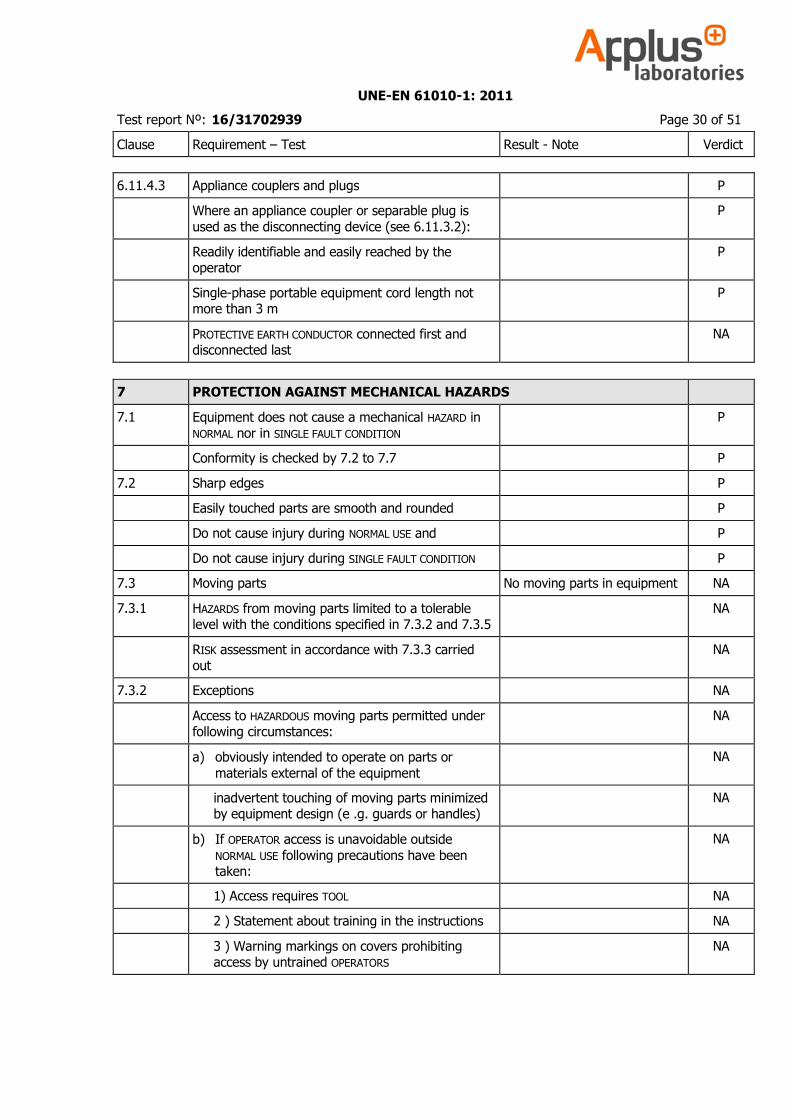
6.11.4.3 Appliance couplers and plugs P
Where an appliance coupler or separable plug is
used as the disconnecting device (see 6.11.3.2):
P
Readily identifiable and easily reached by the operator
P
Single-phase portable equipment cord length not more than 3 m
P
PROTECTIVE EARTH CONDUCTOR connected first and disconnected last
NA
7 PROTECTION AGAINST MECHANICAL HAZARDS
7.1 Equipment does not cause a mechanical HAZARD in NORMAL nor in SINGLE FAULT CONDITION
P
Conformity is checked by 7.2 to 7.7 P
7.2 Sharp edges P
Easily touched parts are smooth and rounded P
Do not cause injury during NORMAL USE and P
Do not cause injury during SINGLE FAULT CONDITION P
7.3 Moving parts No moving parts in equipment NA
7.3.1 HAZARDS from moving parts limited to a tolerable level with the conditions specified in 7.3.2 and 7.3.5
NA
RISK assessment in accordance with 7.3.3 carried out
NA
7.3.2 Exceptions NA
Access to HAZARDOUS moving parts permitted under following circumstances:
NA
a) obviously intended to operate on parts or
materials external of the equipment
NA
inadvertent touching of moving parts minimized by equipment design (e .g. guards or handles)
NA
b) If OPERATOR access is unavoidable outside
NORMAL USE following precautions have been taken:
NA
1) Access requires TOOL NA
2 ) Statement about training in the instructions NA
3 ) Warning markings on covers prohibiting access by untrained OPERATORS
NA
UNE-EN 61010-1: 2011
Test report Nº: 16/31702939 Page 31 of 51
Clause Requirement – Test Result - Note Verdict
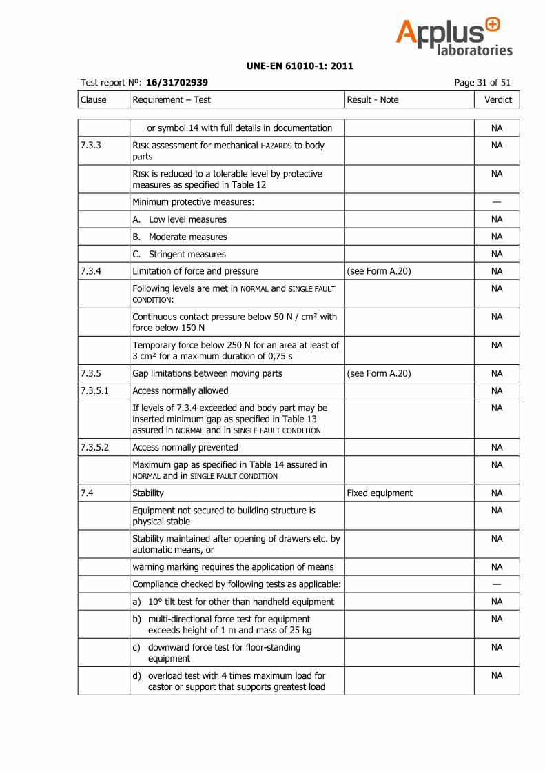
or symbol 14 with full details in documentation NA
7.3.3 RISK assessment for mechanical HAZARDS to body
parts
NA
RISK is reduced to a tolerable level by protective measures as specified in Table 12
NA
Minimum protective measures: —
A. Low level measures NA
B. Moderate measures NA
C. Stringent measures NA
7.3.4 Limitation of force and pressure (see Form A.20) NA
Following levels are met in NORMAL and SINGLE FAULT CONDITION:
NA
Continuous contact pressure below 50 N / cm² with force below 150 N
NA
Temporary force below 250 N for an area at least of 3 cm² for a maximum duration of 0,75 s
NA
7.3.5 Gap limitations between moving parts (see Form A.20) NA
7.3.5.1 Access normally allowed NA
If levels of 7.3.4 exceeded and body part may be
inserted minimum gap as specified in Table 13 assured in NORMAL and in SINGLE FAULT CONDITION
NA
7.3.5.2 Access normally prevented NA
Maximum gap as specified in Table 14 assured in NORMAL and in SINGLE FAULT CONDITION
NA
7.4 Stability Fixed equipment NA
Equipment not secured to building structure is physical stable
NA
Stability maintained after opening of drawers etc. by automatic means, or
NA
warning marking requires the application of means NA
Compliance checked by following tests as applicable: —
a) 10° tilt test for other than handheld equipment NA
b) multi-directional force test for equipment exceeds height of 1 m and mass of 25 kg
NA
c) downward force test for floor-standing
equipment
NA
d) overload test with 4 times maximum load for castor or support that supports greatest load
NA
UNE-EN 61010-1: 2011
Test report Nº: 16/31702939 Page 32 of 51
Clause Requirement – Test Result - Note Verdict
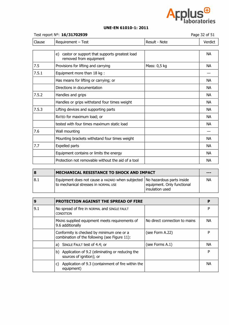
e) castor or support that supports greatest load removed from equipment
NA
7.5 Provisions for lifting and carrying Mass: 0,5 kg NA
7.5.1 Equipment more than 18 kg : —
Has means for lifting or carrying; or NA
Directions in documentation NA
7.5.2 Handles and grips NA
Handles or grips withstand four times weight NA
7.5.3 Lifting devices and supporting parts NA
RATED for maximum load; or NA
tested with four times maximum static load NA
7.6 Wall mounting —
Mounting brackets withstand four times weight NA
7.7 Expelled parts NA
Equipment contains or limits the energy NA
Protection not removable without the aid of a tool NA
8 MECHANICAL RESISTANCE TO SHOCK AND IMPACT ---
8.1 Equipment does not cause a HAZARD when subjected
to mechanical stresses in NORMAL USE
No hazardous parts inside
equipment. Only functional insulation used
NA
9 PROTECTION AGAINST THE SPREAD OF FIRE P
9.1 No spread of fire in NORMAL and SINGLE FAULT
CONDITION
P
MAINS supplied equipment meets requirements of 9.6 additionally
No direct connection to mains NA
Conformity is checked by minimum one or a combination of the following (see Figure 11):
(see Form A.22) P
a) SINGLE FAULT test of 4.4; or (see Forms A.1) NA
b) Application of 9.2 (eliminating or reducing the
sources of ignition); or
P
c) Application of 9.3 (containment of fire within the equipment)
NA
UNE-EN 61010-1: 2011
Test report Nº: 16/31702939 Page 33 of 51
Clause Requirement – Test Result - Note Verdict
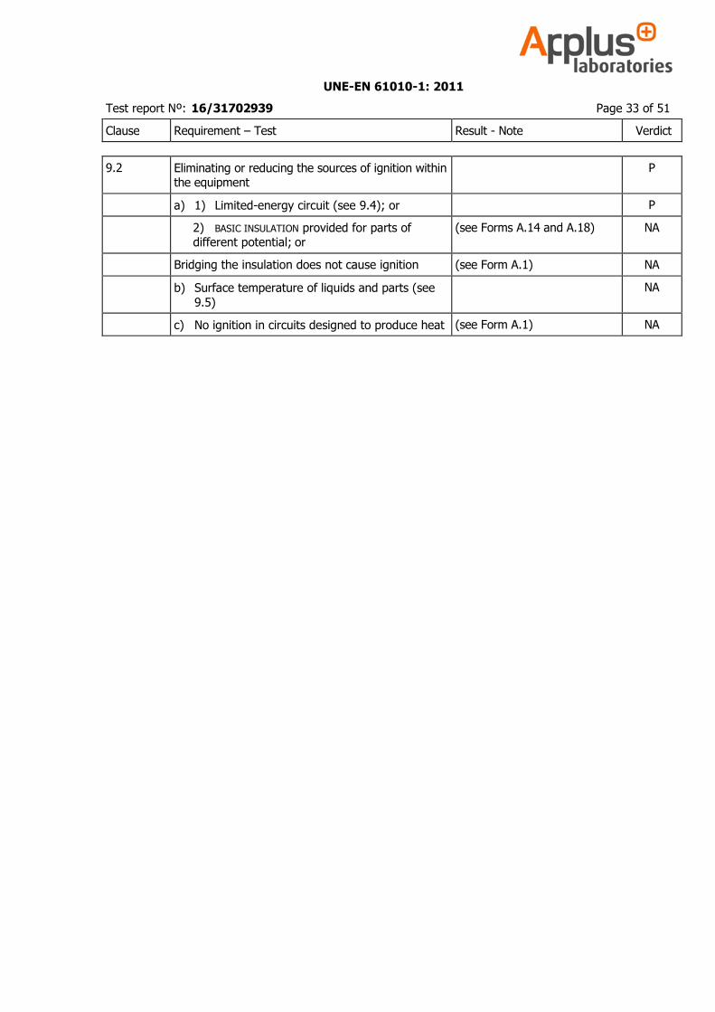
9.2 Eliminating or reducing the sources of ignition within the equipment
P
a) 1) Limited-energy circuit (see 9.4); or P
2) BASIC INSULATION provided for parts of different potential; or
(see Forms A.14 and A.18) NA
Bridging the insulation does not cause ignition (see Form A.1) NA
b) Surface temperature of liquids and parts (see
9.5)
NA
c) No ignition in circuits designed to produce heat (see Form A.1) NA
UNE-EN 61010-1: 2011
Test report Nº: 16/31702939 Page 34 of 51
Clause Requirement – Test Result - Note Verdict
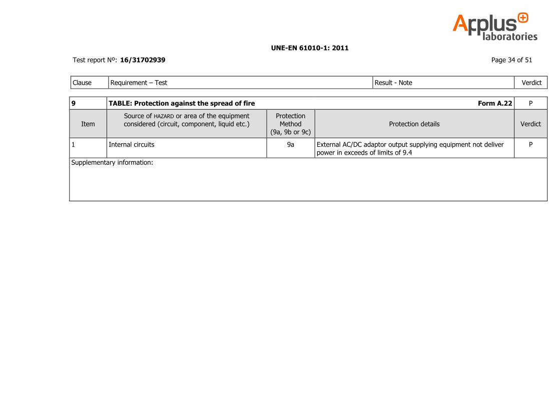
9 TABLE: Protection against the spread of fire Form A.22 P
Item
Source of HAZARD or area of the equipment
considered (circuit, component, liquid etc.)
Protection
Method (9a, 9b or 9c)
Protection details
Verdict
1 Internal circuits 9a External AC/DC adaptor output supplying equipment not deliver
power in exceeds of limits of 9.4
P
Supplementary information:
UNE-EN 61010-1: 2011
Test report Nº: 16/31702939 Page 35 of 51
Clause Requirement – Test Result - Note Verdict
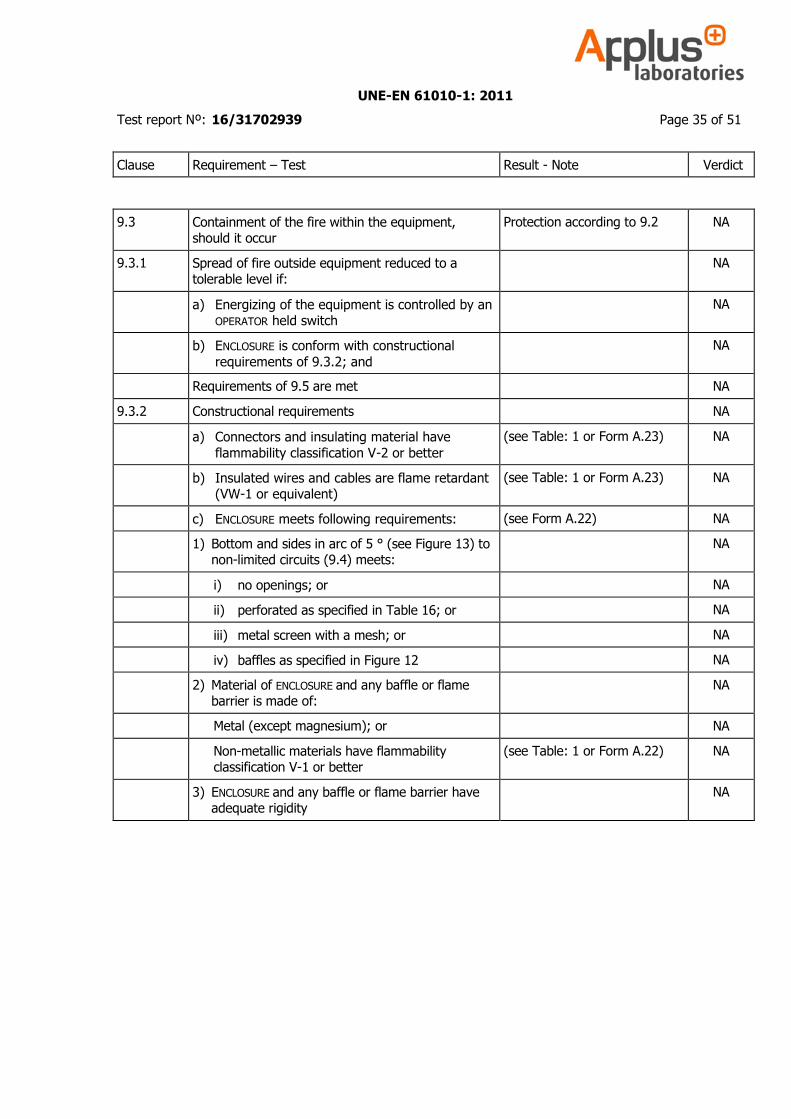
9.3 Containment of the fire within the equipment, should it occur
Protection according to 9.2 NA
9.3.1 Spread of fire outside equipment reduced to a tolerable level if:
NA
a) Energizing of the equipment is controlled by an OPERATOR held switch
NA
b) ENCLOSURE is conform with constructional
requirements of 9.3.2; and
NA
Requirements of 9.5 are met NA
9.3.2 Constructional requirements NA
a) Connectors and insulating material have
flammability classification V-2 or better
(see Table: 1 or Form A.23) NA
b) Insulated wires and cables are flame retardant (VW-1 or equivalent)
(see Table: 1 or Form A.23) NA
c) ENCLOSURE meets following requirements: (see Form A.22) NA
1) Bottom and sides in arc of 5 ° (see Figure 13) to non-limited circuits (9.4) meets:
NA
i) no openings; or NA
ii) perforated as specified in Table 16; or NA
iii) metal screen with a mesh; or NA
iv) baffles as specified in Figure 12 NA
2) Material of ENCLOSURE and any baffle or flame barrier is made of:
NA
Metal (except magnesium); or NA
Non-metallic materials have flammability classification V-1 or better
(see Table: 1 or Form A.22) NA
3) ENCLOSURE and any baffle or flame barrier have adequate rigidity
NA
UNE-EN 61010-1: 2011
Test report Nº: 16/31702939 Page 36 of 51
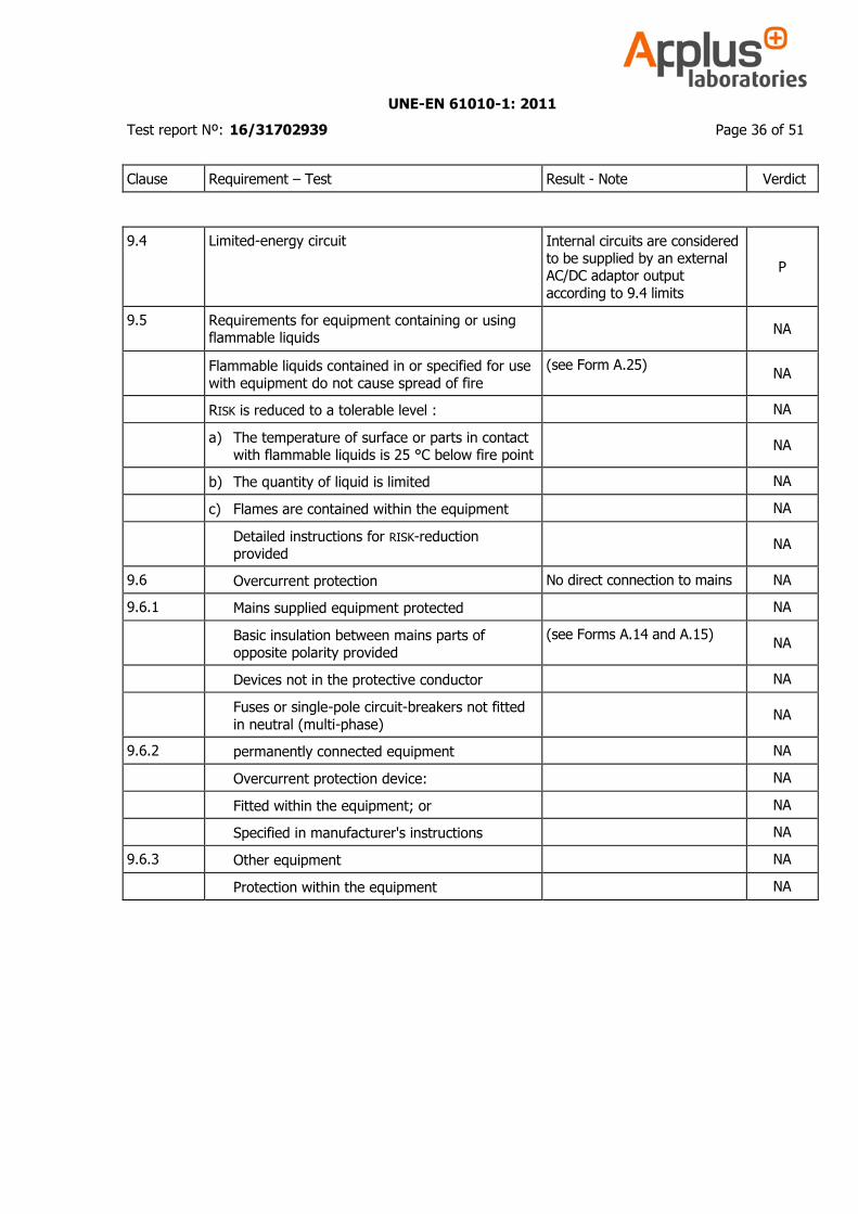
Clause Requirement – Test Result - Note Verdict
9.4 Limited-energy circuit Internal circuits are considered to be supplied by an external AC/DC adaptor output
according to 9.4 limits
P
9.5 Requirements for equipment containing or using flammable liquids
NA
Flammable liquids contained in or specified for use with equipment do not cause spread of fire
(see Form A.25) NA
RISK is reduced to a tolerable level : NA
a) The temperature of surface or parts in contact with flammable liquids is 25 °C below fire point
NA
b) The quantity of liquid is limited NA
c) Flames are contained within the equipment NA
Detailed instructions for RISK-reduction provided
NA
9.6 Overcurrent protection No direct connection to mains NA
9.6.1 Mains supplied equipment protected NA
Basic insulation between mains parts of opposite polarity provided
(see Forms A.14 and A.15) NA
Devices not in the protective conductor NA
Fuses or single-pole circuit-breakers not fitted
in neutral (multi-phase)
NA
9.6.2 permanently connected equipment NA
Overcurrent protection device: NA
Fitted within the equipment; or NA
Specified in manufacturer's instructions NA
9.6.3 Other equipment NA
Protection within the equipment NA
UNE-EN 61010-1: 2011
Test report Nº: 16/31702939 Page 37 of 51
Clause Requirement – Test Result - Note Verdict
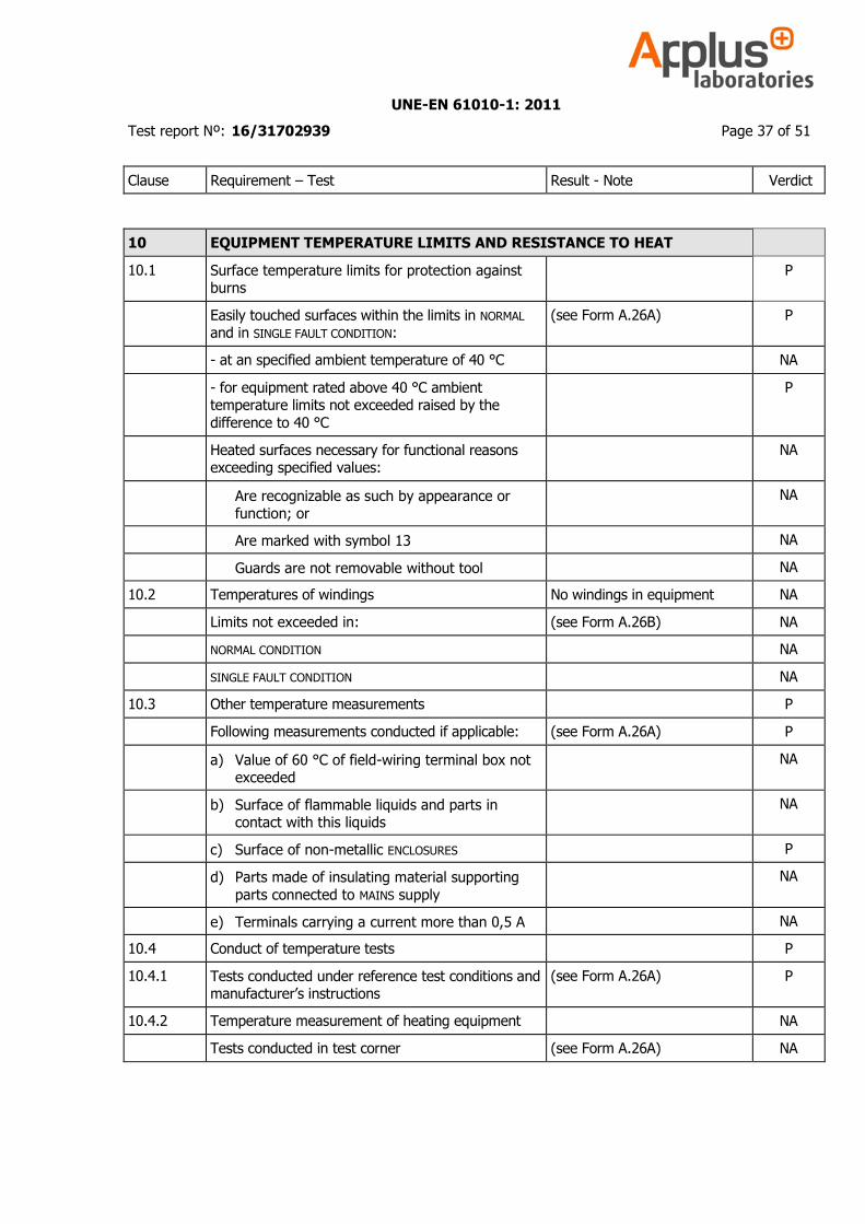
10 EQUIPMENT TEMPERATURE LIMITS AND RESISTANCE TO HEAT
10.1 Surface temperature limits for protection against burns
P
Easily touched surfaces within the limits in NORMAL and in SINGLE FAULT CONDITION:
(see Form A.26A) P
- at an specified ambient temperature of 40 °C NA
- for equipment rated above 40 °C ambient temperature limits not exceeded raised by the
difference to 40 °C
P
Heated surfaces necessary for functional reasons exceeding specified values:
NA
Are recognizable as such by appearance or function; or
NA
Are marked with symbol 13 NA
Guards are not removable without tool NA
10.2 Temperatures of windings No windings in equipment NA
Limits not exceeded in: (see Form A.26B) NA
NORMAL CONDITION NA
SINGLE FAULT CONDITION NA
10.3 Other temperature measurements P
Following measurements conducted if applicable: (see Form A.26A) P
a) Value of 60 °C of field-wiring terminal box not exceeded
NA
b) Surface of flammable liquids and parts in contact with this liquids
NA
c) Surface of non-metallic ENCLOSURES P
d) Parts made of insulating material supporting
parts connected to MAINS supply
NA
e) Terminals carrying a current more than 0,5 A NA
10.4 Conduct of temperature tests P
10.4.1 Tests conducted under reference test conditions and manufacturer’s instructions
(see Form A.26A) P
10.4.2 Temperature measurement of heating equipment NA
Tests conducted in test corner (see Form A.26A) NA
UNE-EN 61010-1: 2011
Test report Nº: 16/31702939 Page 38 of 51
Clause Requirement – Test Result - Note Verdict
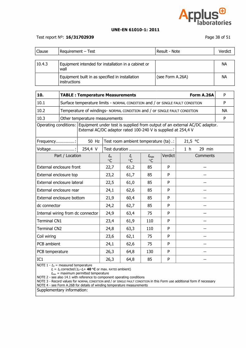
10.4.3 Equipment intended for installation in a cabinet or wall
NA
Equipment built in as specified in installation instructions
(see Form A.26A) NA
10. TABLE : Temperature Measurements Form A.26A P
10.1 Surface temperature limits - NORMAL CONDITION and / or SINGLE FAULT CONDITION P
10.2 Temperature of windings- NORMAL CONDITION and / or SINGLE FAULT CONDITION NA
10.3 Other temperature measurements P
Operating conditions: Equipment under test is supplied from output of an external AC/DC adaptor.
External AC/DC adaptor rated 100-240 V is supplied at 254,4 V
Frequency............... : 50 Hz Test room ambient temperature (ta) . : 21,5 °C
Voltage ................... : 254,4 V Test duration ................................... : 1 h 29 min
Part / Location tm
C
tc
C
tmax
C
Verdict Comments
External enclosure front 22,7 61,2 85 P --
External enclosure top 23,2 61,7 85 P --
External enclosure lateral 22,5 61,0 85 P --
External enclosure rear 24,1 62,6 85 P --
External enclosure bottom 21,9 60,4 85 P --
dc connector 24,2 62,7 85 P --
Internal wiring from dc connector 24,9 63,4 75 P --
Terminal CN1 23,4 61,9 110 P --
Terminal CN2 24,8 63,3 110 P --
Coil wiring 23,6 62,1 75 P --
PCB ambient 24,1 62,6 75 P --
PCB temperature 26,3 64,8 130 P --
IC1 26,3 64,8 85 P --
NOTE 1 - tm = measured temperature tc = tm corrected (tm–ta+ 40 C or max. RATED ambient) tmax = maximum permitted temperature NOTE 2 - see also 14.1 with reference to component operating conditions NOTE 3 - Record values for NORMAL CONDITION and / or SINGLE FAULT CONDITION in this Form use additional form if necessary NOTE 4 - see Form A.26B for details of winding temperature measurements
Supplementary information:
UNE-EN 61010-1: 2011
Test report Nº: 16/31702939 Page 39 of 51
Clause Requirement – Test Result - Note Verdict
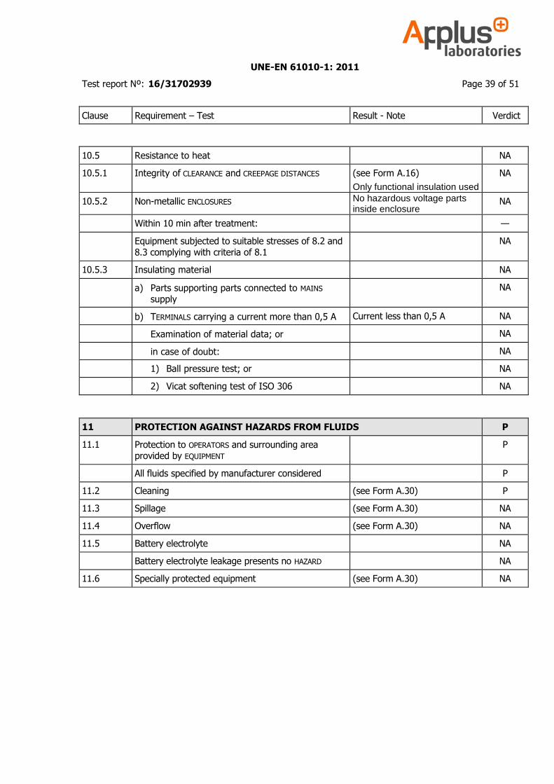
10.5 Resistance to heat NA
10.5.1 Integrity of CLEARANCE and CREEPAGE DISTANCES (see Form A.16)
Only functional insulation used
NA
10.5.2 Non-metallic ENCLOSURES No hazardous voltage parts inside enclosure
NA
Within 10 min after treatment: —
Equipment subjected to suitable stresses of 8.2 and 8.3 complying with criteria of 8.1
NA
10.5.3 Insulating material NA
a) Parts supporting parts connected to MAINS supply
NA
b) TERMINALS carrying a current more than 0,5 A Current less than 0,5 A NA
Examination of material data; or NA
in case of doubt: NA
1) Ball pressure test; or NA
2) Vicat softening test of ISO 306 NA
11 PROTECTION AGAINST HAZARDS FROM FLUIDS P
11.1 Protection to OPERATORS and surrounding area provided by EQUIPMENT
P
All fluids specified by manufacturer considered P
11.2 Cleaning (see Form A.30) P
11.3 Spillage (see Form A.30) NA
11.4 Overflow (see Form A.30) NA
11.5 Battery electrolyte NA
Battery electrolyte leakage presents no HAZARD NA
11.6 Specially protected equipment (see Form A.30) NA
UNE-EN 61010-1: 2011
Test report Nº: 16/31702939 Page 40 of 51
Clause Requirement – Test Result - Note Verdict
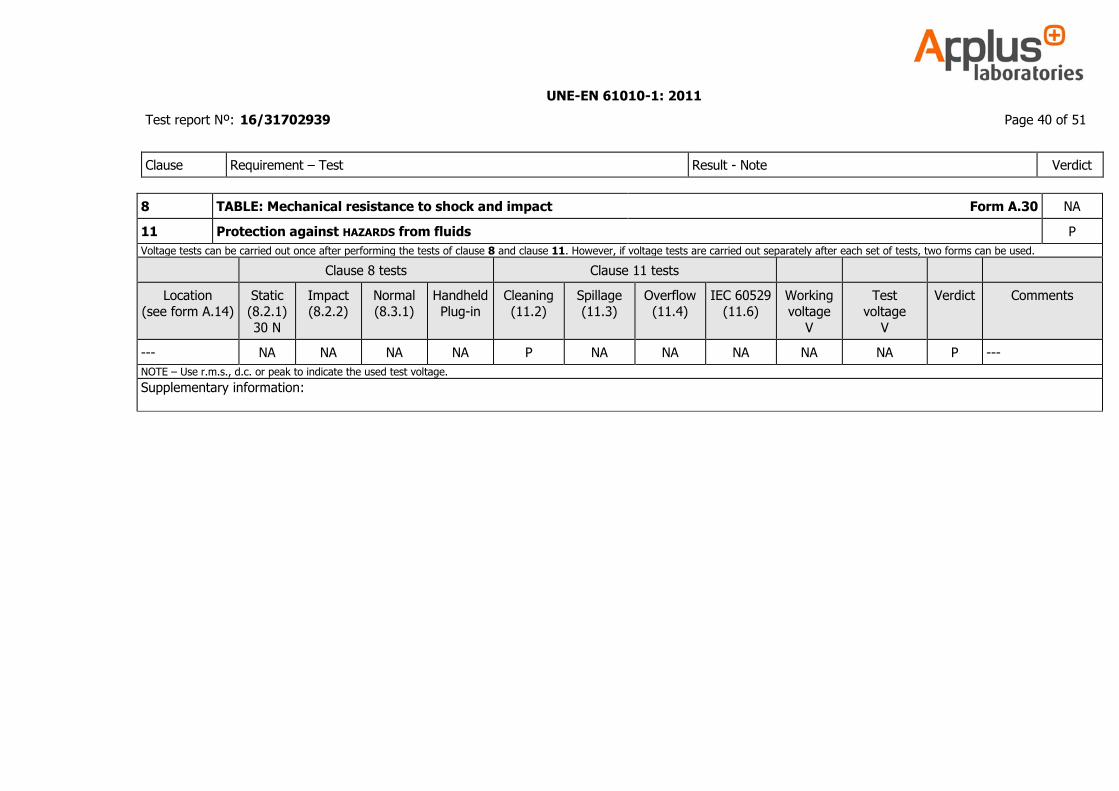
8 TABLE: Mechanical resistance to shock and impact Form A.30 NA
11 Protection against HAZARDS from fluids P
Voltage tests can be carried out once after performing the tests of clause 8 and clause 11. However, if voltage tests are carried out separately after each set of tests, two forms can be used.
Clause 8 tests Clause 11 tests
Location
(see form A.14)
Static
(8.2.1)
30 N
Impact
(8.2.2)
Normal
(8.3.1)
Handheld
Plug-in
Cleaning
(11.2)
Spillage
(11.3)
Overflow
(11.4)
IEC 60529
(11.6)
Working
voltage
V
Test
voltage
V
Verdict Comments
--- NA NA NA NA P NA NA NA NA NA P ---
NOTE – Use r.m.s., d.c. or peak to indicate the used test voltage.
Supplementary information:
UNE-EN 61010-1: 2011
Test report Nº: 16/31702939 Page 41 of 51
Clause Requirement – Test Result - Note Verdict
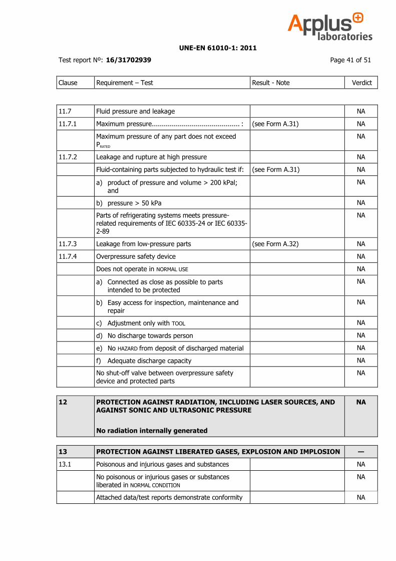
11.7 Fluid pressure and leakage NA
11.7.1 Maximum pressure............................................ : (see Form A.31) NA
Maximum pressure of any part does not exceed
PRATED
NA
11.7.2 Leakage and rupture at high pressure NA
Fluid-containing parts subjected to hydraulic test if: (see Form A.31) NA
a) product of pressure and volume > 200 kPal; and
NA
b) pressure > 50 kPa NA
Parts of refrigerating systems meets pressure-related requirements of IEC 60335-24 or IEC 60335-2-89
NA
11.7.3 Leakage from low-pressure parts (see Form A.32) NA
11.7.4 Overpressure safety device NA
Does not operate in NORMAL USE NA
a) Connected as close as possible to parts intended to be protected
NA
b) Easy access for inspection, maintenance and repair
NA
c) Adjustment only with TOOL NA
d) No discharge towards person NA
e) No HAZARD from deposit of discharged material NA
f) Adequate discharge capacity NA
No shut-off valve between overpressure safety
device and protected parts
NA
12 PROTECTION AGAINST RADIATION, INCLUDING LASER SOURCES, AND AGAINST SONIC AND ULTRASONIC PRESSURE
No radiation internally generated
NA
13 PROTECTION AGAINST LIBERATED GASES, EXPLOSION AND IMPLOSION —
13.1 Poisonous and injurious gases and substances NA
No poisonous or injurious gases or substances liberated in NORMAL CONDITION
NA
Attached data/test reports demonstrate conformity NA
UNE-EN 61010-1: 2011
Test report Nº: 16/31702939 Page 42 of 51
Clause Requirement – Test Result - Note Verdict
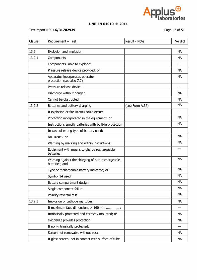
13.2 Explosion and implosion NA
13.2.1 Components NA
Components liable to explode: —
Pressure release device provided; or NA
Apparatus incorporates operator protection (see also 7.7)
NA
Pressure release device: —
Discharge without danger NA
Cannot be obstructed NA
13.2.2 Batteries and battery charging (see Form A.37) NA
If explosion or fire HAZARD could occur: —
Protection incorporated in the equipment; or NA
Instructions specify batteries with built-in protection NA
In case of wrong type of battery used: —
No HAZARD; or NA
Warning by marking and within instructions NA
Equipment with means to charge rechargeable batteries:
—
Warning against the charging of non-rechargeable batteries; and
NA
Type of rechargeable battery indicated; or NA
Symbol 14 used NA
Battery compartment design NA
Single component failure NA
Polarity reversal test NA
13.2.3 Implosion of cathode ray tubes NA
If maximum face dimensions > 160 mm .............. : —
Intrinsically protected and correctly mounted; or NA
ENCLOSURE provides protection: NA
If non-intrinsically protected: —
Screen not removable without TOOL NA
If glass screen, not in contact with surface of tube NA
UNE-EN 61010-1: 2011
Test report Nº: 16/31702939 Page 43 of 51
Clause Requirement – Test Result - Note Verdict
14 COMPONENTS P
14.1 Where safety is involved, components and subassemblies meet relevant requirements
(see Table 1) P
UNE-EN 61010-1: 2011
Test report Nº: 16/31702939 Page 44 of 51
Clause Requirement – Test Result - Note Verdict
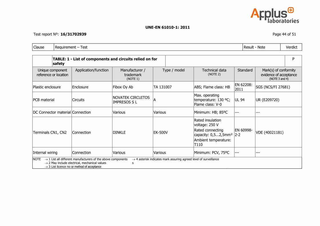
TABLE: 1 - List of components and circuits relied on for safety
P
Unique component
reference or location
Application/function Manufacturer /
trademark (NOTE 1)
Type / model Technical data
(NOTE 2) Standard
Mark(s) of conformity
evidence of acceptance (NOTE 3 and 4)
Plastic enclosure Enclosure Fibox Oy Ab TA 131007 ABS; Flame class: HB EN 62208: 2011
SGS (NCS/FI 27681)
PCB material Circuits NOVATEK CIRCUITOS IMPRESOS S L
A Max. operating temperature: 130 ºC;
Flame class: V-0
UL 94 UR (E209720)
DC Connector material Connection Various Various Minimum: HB; 85ºC --- ---
Terminals CN1, CN2 Connection DINKLE EK-500V
Rated insulation
voltage: 250 V
Rated connecting
capacity: 0,5...2,5mm²
Ambient temperature:
T110
EN 60998-
2-2 VDE (40021181)
Internal wiring Connection Various Various Minimum: PCV, 75ºC --- ---
NOTE 1 List all different manufacturers of the above components 4 asterisk indicates mark assuring agreed level of surveillance
2 May include electrical, mechanical values s
3 List licence no or method of acceptance
UNE-EN 61010-1: 2011
Test report Nº: 16/31702939 Page 45 of 51
Clause Requirement – Test Result - Note Verdict
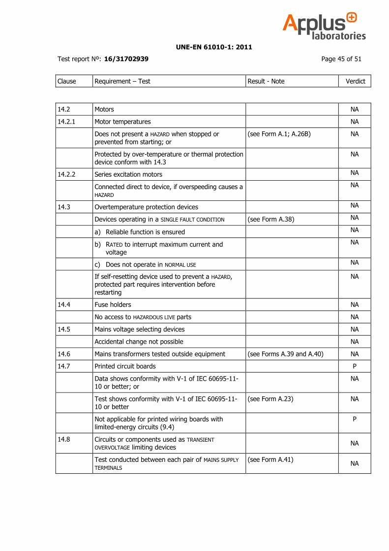
14.2 Motors NA
14.2.1 Motor temperatures NA
Does not present a HAZARD when stopped or
prevented from starting; or
(see Form A.1; A.26B) NA
Protected by over-temperature or thermal protection device conform with 14.3
NA
14.2.2 Series excitation motors NA
Connected direct to device, if overspeeding causes a HAZARD
NA
14.3 Overtemperature protection devices NA
Devices operating in a SINGLE FAULT CONDITION (see Form A.38) NA
a) Reliable function is ensured NA
b) RATED to interrupt maximum current and voltage
NA
c) Does not operate in NORMAL USE NA
If self-resetting device used to prevent a HAZARD, protected part requires intervention before
restarting
NA
14.4 Fuse holders NA
No access to HAZARDOUS LIVE parts NA
14.5 Mains voltage selecting devices NA
Accidental change not possible NA
14.6 Mains transformers tested outside equipment (see Forms A.39 and A.40) NA
14.7 Printed circuit boards P
Data shows conformity with V-1 of IEC 60695-11-10 or better; or
NA
Test shows conformity with V-1 of IEC 60695-11-10 or better
(see Form A.23) NA
Not applicable for printed wiring boards with limited-energy circuits (9.4)
P
14.8 Circuits or components used as TRANSIENT OVERVOLTAGE limiting devices
NA
Test conducted between each pair of MAINS SUPPLY
TERMINALS
(see Form A.41) NA
UNE-EN 61010-1: 2011
Test report Nº: 16/31702939 Page 46 of 51
Clause Requirement – Test Result - Note Verdict
No HAZARD resulting from rupture or overheating of the component:
NA
- no bridging of safety relevant insulation NA
- no heat to other parts above the self-ignition
points
—
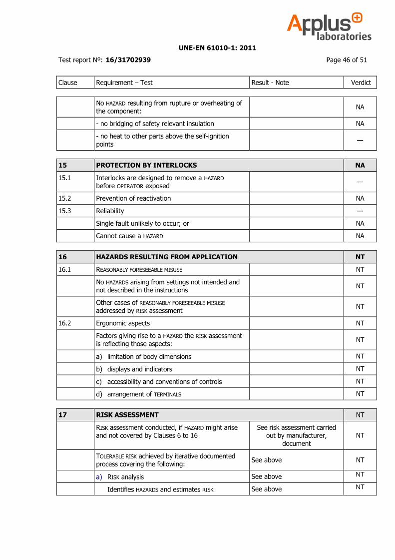
15 PROTECTION BY INTERLOCKS NA
15.1 Interlocks are designed to remove a HAZARD before OPERATOR exposed
—
15.2 Prevention of reactivation NA
15.3 Reliability —
Single fault unlikely to occur; or NA
Cannot cause a HAZARD NA
16 HAZARDS RESULTING FROM APPLICATION NT
16.1 REASONABLY FORESEEABLE MISUSE NT
No HAZARDS arising from settings not intended and not described in the instructions
NT
Other cases of REASONABLY FORESEEABLE MISUSE addressed by RISK assessment
NT
16.2 Ergonomic aspects NT
Factors giving rise to a HAZARD the RISK assessment
is reflecting those aspects: NT
a) limitation of body dimensions NT
b) displays and indicators NT
c) accessibility and conventions of controls NT
d) arrangement of TERMINALS NT
17 RISK ASSESSMENT NT
RISK assessment conducted, if HAZARD might arise and not covered by Clauses 6 to 16
See risk assessment carried out by manufacturer,
document
NT
TOLERABLE RISK achieved by iterative documented process covering the following:
See above NT
a) RISK analysis See above NT
Identifies HAZARDS and estimates RISK See above NT
UNE-EN 61010-1: 2011
Test report Nº: 16/31702939 Page 47 of 51
Clause Requirement – Test Result - Note Verdict
b) RISK evaluation See above NT
Plan to judge acceptability of resulting RISK level based on the estimated severity and likelihood
of a RISK
See above NT
c) RISK reduction See above NT
Initial RISK reduced by counter measures; See above NT
Repeated RISK evaluation without new RISKS introduced
See above NT
RISKS remaining after RISK assessment addressed in instructions to RESPONSIBLE BODY:
See above NT
Information contained how to mitigate these RISKS See above NT
Following principles in methods of RISK reduction applied by manufacturer in given order:
See above NT
1) RISKS eliminated or reduced as far as possible See above NT
2) Protective measures taken for RISKS that cannot be eliminated
See above NT
3) User information about residual RISK due to any defect of the protective measures
See above NT
Indication of particular training is required See above NT
Specification of the need for personal protective equipment
See above NT
Conformity checked by evaluation of the RISK assessment documentation
See above NT
ANNEX F ROUTINE TESTS NA
Manufacturer’s declaration NA

UNE-EN 61010-1: 2011
Test report Nº: 16/31702939 Page 48 of 51
ANNEX A: PICTURES
External view of EUT
Marking in equipment
UNE-EN 61010-1: 2011
Test report Nº: 16/31702939 Page 49 of 51
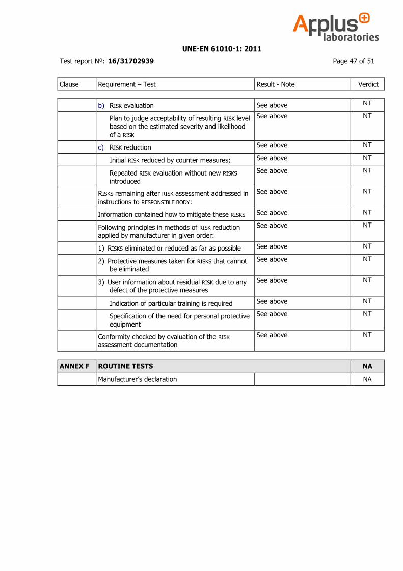
Lateral view of equipment
Rear view of equipment
UNE-EN 61010-1: 2011
Test report Nº: 16/31702939 Page 50 of 51
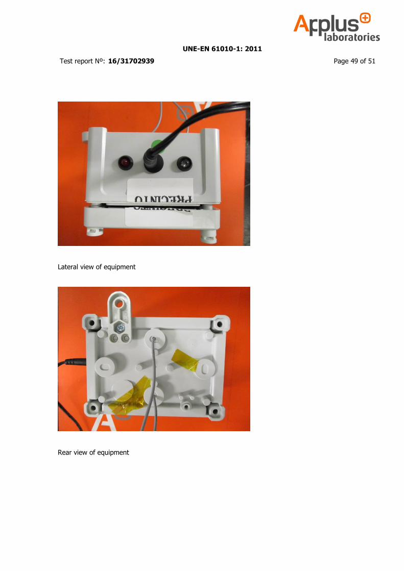
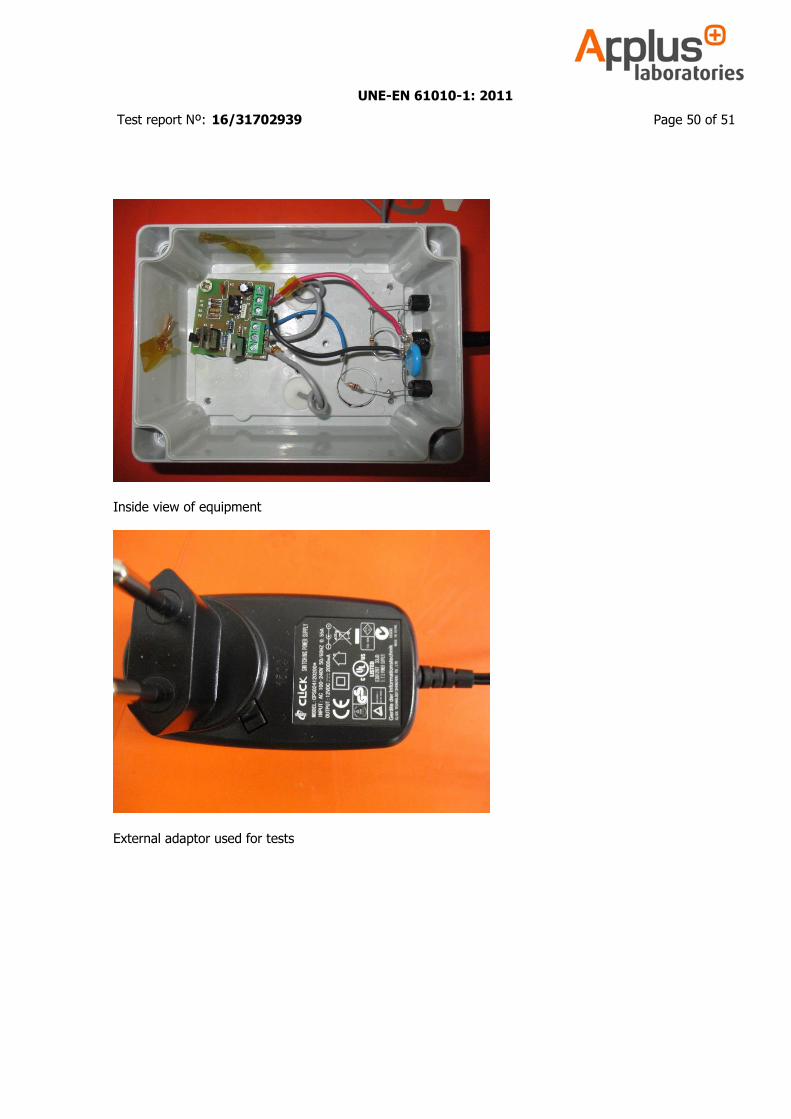
Inside view of equipment
External adaptor used for tests

UNE-EN 61010-1: 2011
Test report Nº: 16/31702939 Page 51 of 51
PCB top view
PCB bottom view