informational proposal - nebraska3).pdf · informational proposal ... asphalt raker .....$ 11 ......
TRANSCRIPT
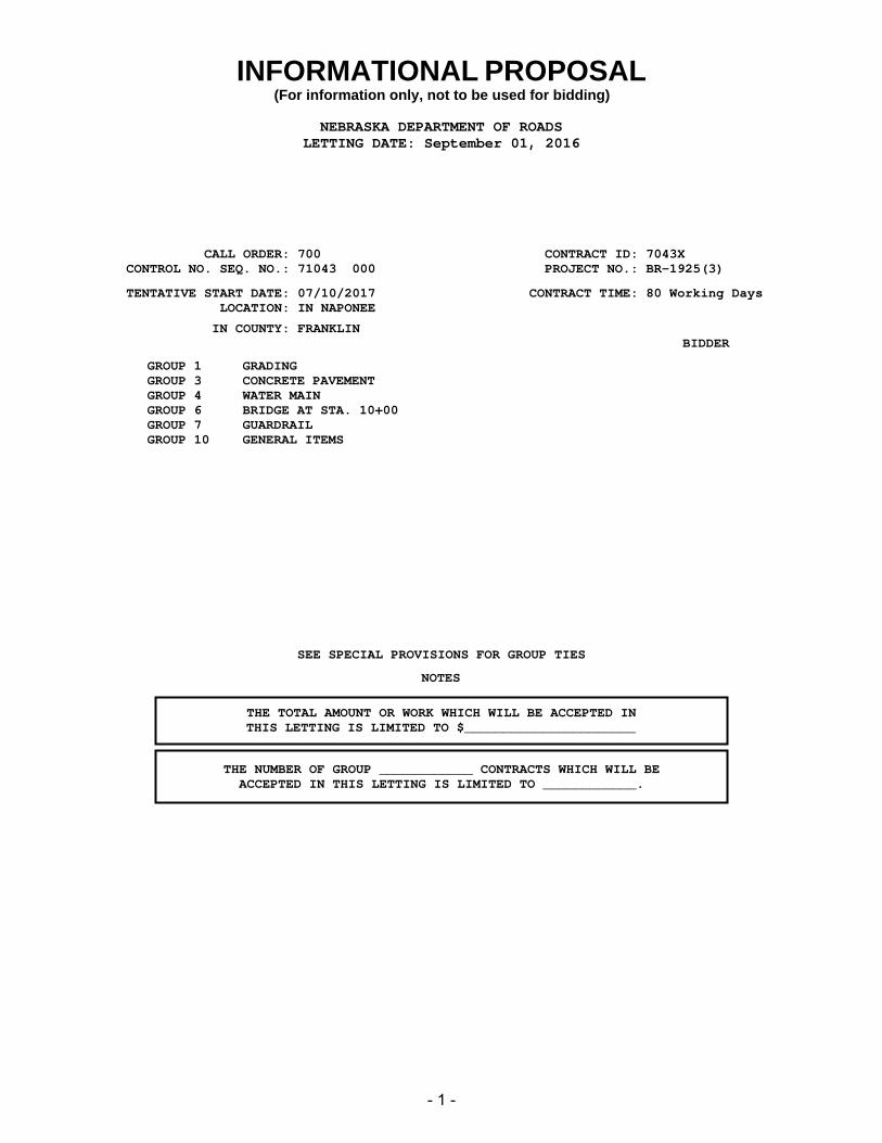
INFORMATIONAL PROPOSAL(For information only, not to be used for bidding)
NEBRASKA DEPARTMENT OF ROADSLETTING DATE: September 01, 2016
CALL ORDER: 700 CONTRACT ID: 7043XCONTROL NO. SEQ. NO.: 71043 000 PROJECT NO.: BR-1925(3)
TENTATIVE START DATE: 07/10/2017 CONTRACT TIME: 80 Working DaysLOCATION: IN NAPONEE
IN COUNTY: FRANKLINBIDDER
GROUP 1GROUP 3GROUP 4GROUP 6GROUP 7GROUP 10
GRADING CONCRETE PAVEMENT WATER MAIN BRIDGE AT STA. 10+00 GUARDRAIL GENERAL ITEMS
SEE SPECIAL PROVISIONS FOR GROUP TIES
THE TOTAL AMOUNT OR WORK WHICH WILL BE ACCEPTED INTHIS LETTING IS LIMITED TO $______________________
THE NUMBER OF GROUP ____________ CONTRACTS WHICH WILL BEACCEPTED IN THIS LETTING IS LIMITED TO ____________.
NOTES
- 1 -

Project No. BR-1925(3)
- 2 -
NOTICE TO ALL BIDDERS To report bid rigging activities, call: 1-800-424-9071 The U.S. Department of Transportation (DOT) operates the above toll-free “hotline” Monday through Friday, 8:00 a.m. to 5:00 p.m. eastern time. Anyone with knowledge of possible bid rigging, bidder collusion, or other fraudulent activities should use the “hotline” to report such activities. The “hotline” is part of the DOT’s continuing effort to identify and investigate highway construction contract fraud and abuse and is operated under the direction of the DOT Inspector General. All information will be treated confidentially and caller anonymity will be respected.
LETTING QUESTIONS
Prior to the letting, any questions pertaining to the Special Provisions or the Plans for this project should be submitted to NDOR in a written format through the Bid Express (BidX) website at https://www.bidx.com/ne/lettings. Likewise, NDOR will post answers exclusively to the BidX website. All official answers will be identified as “Authorized by NDOR.” Questions will not be answered verbally.
Project No. BR-1925(3)
- 3 -
Project No. BR-1925(3)
- 4 -

Project No. BR-1925(3)
- 5 -
Project No. BR-1925(3)
- 6 -

Project No. BR-1925(3)
- 7 -

Project No. BR-1925(3)
- 8 -

Project No. BR-1925(3)
- 9 -

Project No. BR-1925(3)
- 10 -
Project No. BR-1925(3)
- 11 -

Project No. BR-1925(3)
- 12 -

Project No. BR-1925(3)
- 13 -

Project No. BR-1925(3)
- 14 -

Project No. BR-1925(3)
- 15 -

Project No. BR-1925(3)
- 16 -
Project No. BR-1925(3)
- 17 -

Project No. BR-1925(3)
- 18 -
Project No. BR-1925(3)
- 19 -
Project No. BR-1925(3)
- 20 -
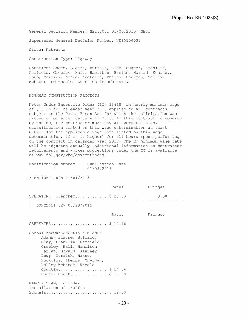
General Decision Number: NE160031 01/08/2016 NE31 Superseded General Decision Number: NE20150031 State: Nebraska Construction Type: Highway Counties: Adams, Blaine, Buffalo, Clay, Custer, Franklin, Garfield, Greeley, Hall, Hamilton, Harlan, Howard, Kearney, Loup, Merrick, Nance, Nuckolls, Phelps, Sherman, Valley, Webster and Wheeler Counties in Nebraska. HIGHWAY CONSTRUCTION PROJECTS Note: Under Executive Order (EO) 13658, an hourly minimum wage of $10.15 for calendar year 2016 applies to all contracts subject to the Davis-Bacon Act for which the solicitation was issued on or after January 1, 2015. If this contract is covered by the EO, the contractor must pay all workers in any classification listed on this wage determination at least $10.15 (or the applicable wage rate listed on this wage determination, if it is higher) for all hours spent performing on the contract in calendar year 2016. The EO minimum wage rate will be adjusted annually. Additional information on contractor requirements and worker protections under the EO is available at www.dol.gov/whd/govcontracts. Modification Number Publication Date 0 01/08/2016 * ENGI0571-005 01/01/2013 Rates Fringes OPERATOR: Trencher..............$ 20.83 9.60 ---------------------------------------------------------------- * SUNE2011-027 08/29/2011 Rates Fringes CARPENTER........................$ 17.16 CEMENT MASON/CONCRETE FINISHER Adams, Blaine, Buffalo, Clay, Franklin, Garfield, Greeley, Hall, Hamilton, Harlan, Howard, Kearney, Loup, Merrick, Nance, Nuckolls, Phelps, Sherman, Valley Webster, Wheele Counties....................$ 14.06 Custer County...............$ 15.38 ELECTRICIAN, Includes Installation of Traffic Signals..........................$ 19.00
Project No. BR-1925(3)
- 21 -
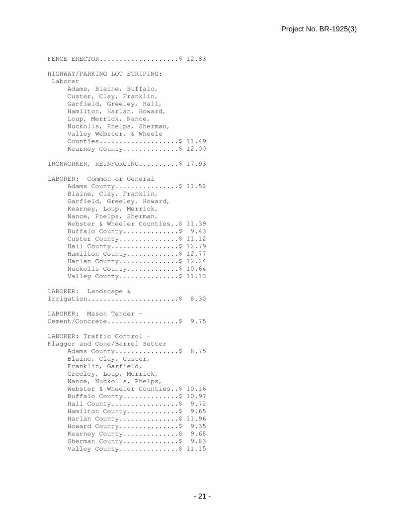
FENCE ERECTOR....................$ 12.83 HIGHWAY/PARKING LOT STRIPING: Laborer Adams, Blaine, Buffalo, Custer, Clay, Franklin, Garfield, Greeley, Hall, Hamilton, Harlan, Howard, Loup, Merrick, Nance, Nuckolls, Phelps, Sherman, Valley Webster, & Wheele Counties....................$ 11.49 Kearney County..............$ 12.00 IRONWORKER, REINFORCING..........$ 17.93 LABORER: Common or General Adams County................$ 11.52 Blaine, Clay, Franklin, Garfield, Greeley, Howard, Kearney, Loup, Merrick, Nance, Phelps, Sherman, Webster & Wheeler Counties..$ 11.39 Buffalo County..............$ 9.43 Custer County...............$ 11.12 Hall County.................$ 12.79 Hamilton County.............$ 12.77 Harlan County...............$ 12.24 Nuckolls County.............$ 10.64 Valley County...............$ 11.13 LABORER: Landscape & Irrigation.......................$ 8.30 LABORER: Mason Tender - Cement/Concrete..................$ 9.75 LABORER: Traffic Control - Flagger and Cone/Barrel Setter Adams County................$ 8.75 Blaine, Clay, Custer, Franklin, Garfield, Greeley, Loup, Merrick, Nance, Nuckolls, Phelps, Webster & Wheeler Counties..$ 10.16 Buffalo County..............$ 10.97 Hall County.................$ 9.72 Hamilton County.............$ 9.65 Harlan County...............$ 11.96 Howard County...............$ 9.35 Kearney County..............$ 9.68 Sherman County..............$ 9.83 Valley County...............$ 11.15
Project No. BR-1925(3)
- 22 -
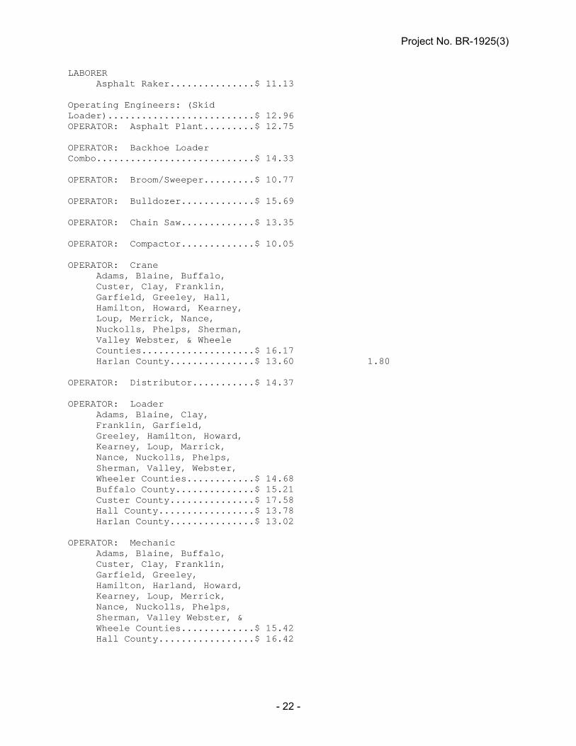
LABORER Asphalt Raker...............$ 11.13 Operating Engineers: (Skid Loader)..........................$ 12.96 OPERATOR: Asphalt Plant.........$ 12.75 OPERATOR: Backhoe Loader Combo............................$ 14.33 OPERATOR: Broom/Sweeper.........$ 10.77 OPERATOR: Bulldozer.............$ 15.69 OPERATOR: Chain Saw.............$ 13.35 OPERATOR: Compactor.............$ 10.05 OPERATOR: Crane Adams, Blaine, Buffalo, Custer, Clay, Franklin, Garfield, Greeley, Hall, Hamilton, Howard, Kearney, Loup, Merrick, Nance, Nuckolls, Phelps, Sherman, Valley Webster, & Wheele Counties....................$ 16.17 Harlan County...............$ 13.60 1.80 OPERATOR: Distributor...........$ 14.37 OPERATOR: Loader Adams, Blaine, Clay, Franklin, Garfield, Greeley, Hamilton, Howard, Kearney, Loup, Marrick, Nance, Nuckolls, Phelps, Sherman, Valley, Webster, Wheeler Counties............$ 14.68 Buffalo County..............$ 15.21 Custer County...............$ 17.58 Hall County.................$ 13.78 Harlan County...............$ 13.02 OPERATOR: Mechanic Adams, Blaine, Buffalo, Custer, Clay, Franklin, Garfield, Greeley, Hamilton, Harland, Howard, Kearney, Loup, Merrick, Nance, Nuckolls, Phelps, Sherman, Valley Webster, & Wheele Counties.............$ 15.42 Hall County.................$ 16.42
Project No. BR-1925(3)
- 23 -
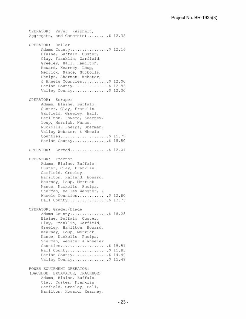
OPERATOR: Paver (Asphalt, Aggregate, and Concrete).........$ 12.35 OPERATOR: Roller Adams County................$ 12.16 Blaine, Buffalo, Custer, Clay, Franklin, Garfield, Greeley, Hall, Hamilton, Howard, Kearney, Loup, Merrick, Nance, Nuckolls, Phelps, Sherman, Webster, & Wheele Counties...........$ 12.00 Harlan County...............$ 12.86 Valley County...............$ 12.30 OPERATOR: Scraper Adams, Blaine, Buffalo, Custer, Clay, Franklin, Garfield, Greeley, Hall, Hamilton, Howard, Kearney, Loup, Merrick, Nance, Nuckolls, Phelps, Sherman, Valley Webster, & Wheele Counties....................$ 15.79 Harlan County...............$ 15.50 OPERATOR: Screed................$ 12.01 OPERATOR: Tractor Adams, Blaine, Buffalo, Custer, Clay, Franklin, Garfield, Greeley, Hamilton, Harland, Howard, Kearney, Loup, Merrick, Nance, Nuckolls, Phelps, Sherman, Valley Webster, & Wheele Counties.............$ 12.80 Hall County.................$ 13.73 OPERATOR: Grader/Blade Adams County................$ 18.25 Blaine, Buffalo, Custer, Clay, Franklin, Garfield, Greeley, Hamilton, Howard, Kearney, Loup, Merrick, Nance, Nuckolls, Phelps, Sherman, Webster & Wheeler Counties....................$ 15.51 Hall County.................$ 15.85 Harlan County...............$ 14.49 Valley County...............$ 15.48 POWER EQUIPMENT OPERATOR: (BACKHOE, EXCAVATOR, TRACKHOE) Adams, Blaine, Buffalo, Clay, Custer, Franklin, Garfield, Greeley, Hall, Hamilton, Howard, Kearney,
Project No. BR-1925(3)
- 24 -
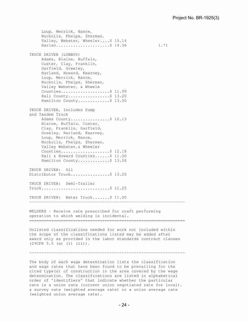
Loup, Merrick, Nance, Nuckolls, Phelps, Sherman, Valley, Webster, Wheeler....$ 15.14 Harlan......................$ 14.36 1.71 TRUCK DRIVER (LOWBOY) Adams, Blaine, Buffalo, Custer, Clay, Franklin, Garfield, Greeley, Harland, Howard, Kearney, Loup, Merrick, Nance, Nuckolls, Phelps, Sherman, Valley Webster, & Wheele Counties....................$ 11.99 Hall County.................$ 13.20 Hamilton County.............$ 13.50 TRUCK DRIVER, Includes Dump and Tandem Truck Adams County................$ 12.13 Blaine, Buffalo, Custer, Clay, Franklin, Garfield, Greeley, Harland, Kearney, Loup, Merrick, Nance, Nuckolls, Phelps, Sherman, Valley Webster,& Wheeler Counties....................$ 12.18 Hall & Howard Counties......$ 11.00 Hamilton County.............$ 13.58 TRUCK DRIVER: Oil Distributor Truck................$ 13.25 TRUCK DRIVER: Semi-Trailer Truck............................$ 11.25 TRUCK DRIVER: Water Truck.......$ 11.00 ---------------------------------------------------------------- WELDERS - Receive rate prescribed for craft performing operation to which welding is incidental. ================================================================ Unlisted classifications needed for work not included within the scope of the classifications listed may be added after award only as provided in the labor standards contract clauses (29CFR 5.5 (a) (1) (ii)). ---------------------------------------------------------------- The body of each wage determination lists the classification and wage rates that have been found to be prevailing for the cited type(s) of construction in the area covered by the wage determination. The classifications are listed in alphabetical order of "identifiers" that indicate whether the particular rate is a union rate (current union negotiated rate for local), a survey rate (weighted average rate) or a union average rate (weighted union average rate).

Project No. BR-1925(3)
- 25 -
Union Rate Identifiers A four letter classification abbreviation identifier enclosed in dotted lines beginning with characters other than "SU" or "UAVG" denotes that the union classification and rate were prevailing for that classification in the survey. Example: PLUM0198-005 07/01/2014. PLUM is an abbreviation identifier of the union which prevailed in the survey for this classification, which in this example would be Plumbers. 0198 indicates the local union number or district council number where applicable, i.e., Plumbers Local 0198. The next number, 005 in the example, is an internal number used in processing the wage determination. 07/01/2014 is the effective date of the most current negotiated rate, which in this example is July 1, 2014. Union prevailing wage rates are updated to reflect all rate changes in the collective bargaining agreement (CBA) governing this classification and rate. Survey Rate Identifiers Classifications listed under the "SU" identifier indicate that no one rate prevailed for this classification in the survey and the published rate is derived by computing a weighted average rate based on all the rates reported in the survey for that classification. As this weighted average rate includes all rates reported in the survey, it may include both union and non-union rates. Example: SULA2012-007 5/13/2014. SU indicates the rates are survey rates based on a weighted average calculation of rates and are not majority rates. LA indicates the State of Louisiana. 2012 is the year of survey on which these classifications and rates are based. The next number, 007 in the example, is an internal number used in producing the wage determination. 5/13/2014 indicates the survey completion date for the classifications and rates under that identifier. Survey wage rates are not updated and remain in effect until a new survey is conducted. Union Average Rate Identifiers Classification(s) listed under the UAVG identifier indicate that no single majority rate prevailed for those classifications; however, 100% of the data reported for the classifications was union data. EXAMPLE: UAVG-OH-0010 08/29/2014. UAVG indicates that the rate is a weighted union average rate. OH indicates the state. The next number, 0010 in the example, is an internal number used in producing the wage determination. 08/29/2014 indicates the survey completion date for the classifications and rates under that identifier. A UAVG rate will be updated once a year, usually in January of each year, to reflect a weighted average of the current negotiated/CBA rate of the union locals from which the rate is based. ----------------------------------------------------------------

Project No. BR-1925(3)
- 26 -
WAGE DETERMINATION APPEALS PROCESS 1.) Has there been an initial decision in the matter? This can be: * an existing published wage determination * a survey underlying a wage determination * a Wage and Hour Division letter setting forth a position on a wage determination matter * a conformance (additional classification and rate) ruling On survey related matters, initial contact, including requests for summaries of surveys, should be with the Wage and Hour Regional Office for the area in which the survey was conducted because those Regional Offices have responsibility for the Davis-Bacon survey program. If the response from this initial contact is not satisfactory, then the process described in 2.) and 3.) should be followed. With regard to any other matter not yet ripe for the formal process described here, initial contact should be with the Branch of Construction Wage Determinations. Write to: Branch of Construction Wage Determinations Wage and Hour Division U.S. Department of Labor 200 Constitution Avenue, N.W. Washington, DC 20210 2.) If the answer to the question in 1.) is yes, then an interested party (those affected by the action) can request review and reconsideration from the Wage and Hour Administrator (See 29 CFR Part 1.8 and 29 CFR Part 7). Write to: Wage and Hour Administrator U.S. Department of Labor 200 Constitution Avenue, N.W. Washington, DC 20210 The request should be accompanied by a full statement of the interested party's position and by any information (wage payment data, project description, area practice material, etc.) that the requestor considers relevant to the issue. 3.) If the decision of the Administrator is not favorable, an interested party may appeal directly to the Administrative Review Board (formerly the Wage Appeals Board). Write to: Administrative Review Board U.S. Department of Labor 200 Constitution Avenue, N.W. Washington, DC 20210 4.) All decisions by the Administrative Review Board are final. ================================================================ END OF GENERAL DECISION
Project No. BR-1925(3)
- 27 -
SPECIAL PROVISIONS FOR
FEDERAL-AID PROJECT NO. BR-1925(3)
GENERAL CONDITIONS
Bids for the work contemplated in this proposal form will be received by the Department of Roads of the State of Nebraska, for the County of Franklin, Nebraska, at the office of the Nebraska Department of Roads in Room 104 of the Central Office Building at 1500 Highway 2 at Lincoln, Nebraska on September 1, 2016, until 1:30 P.M. a. Bids submitted by mail should be addressed to the Nebraska Department of Roads,
c/o Contract Lettings Section, P.O. Box 94759, Lincoln, NE 68509-4759. b. Bids submitted electronically over the internet, shall be submitted using www.bidx.com. The 2007 Edition of the Standard Specifications for Highway Construction, including all amendments and additions thereto effective at the date of the contract, are made a part of these Special Provisions, through reference. The Required Contract Provisions, Form FHWA 1273, (Rev. 5-12), and the Notice of Requirement for Affirmative Action to Ensure Equal Employment Opportunity and Standard Federal Equal Employment Opportunity Construction Contract Specifications dated November 3, 1980, are attached to and are a part of this proposal form. The Standard Labor Classifications and Descriptions for Highway Construction dated September 1, 1996, are made a part of these Special Provisions, through reference. The General Wage Decision issued under the Davis-Bacon and Related Acts is attached to and is a part of this proposal form. The attention of bidders is directed to the Required Contract Provisions covering subletting or assigning the contract. GROUPS 1, 3, 4, 6, 7 & 10 ARE TIED TOGETHER AND BIDDING PROPOSAL FORMS FOR THIS WORK WILL BE ISSUED AND A CONTRACT AWARDED TO A CONTRACTOR WHO IS QUALIFIED FOR BRIDGE.
DISADVANTAGED BUSINESS ENTERPRISES (A-8-0507)
A. Policy The Contractor agrees to ensure that Disadvantaged Business Enterprises as defined in
49 CFR Part 26 shall have a “level playing field” and equal opportunity to participate in the performance of contracts financed in whole or in part with Federal funds under this contract. Consequently, the Disadvantaged Business requirements of 49 CFR Part 26 are hereby made a part of and incorporated by this reference into this contract.
Project No. BR-1925(3)
- 28 -
B. Disadvantaged Business Enterprises Obligation The Contractor agrees to ensure that Disadvantaged Business Enterprises as defined in
49 CFR Part 26 have a “level playing field” and equal opportunity to participate in the performance of contracts and subcontracts financed in whole or in part with Federal funds provided under this agreement. In this regard, the Contractor shall take all necessary and reasonable steps in accordance with 49 CFR Part 26 to ensure that Disadvantaged Business Enterprises have a “level playing field” and equal opportunity to compete for and perform contracts. The Contractor shall not discriminate on the basis of race, color, national origin, or sex in the award and performance of FHWA assisted contracts.
Failure of the Contractor to carry out the requirements set forth above shall constitute breach of contract and, after the notification of the FHWA, may result in termination of the agreement or contract by the State or such remedy as the State deems appropriate.
DISADVANTAGED BUSINESS ENTERPRISES (Prime Contractor Reporting of DBE Payments)
(A-8-1110) This project is funded with Federal Funds and NDOR is required by law to collect DBE payment data from the Contractor. The Prime Contractor shall complete the DBE Total Paid To Date portion on the Monthly Employment Report. This report can be found by using the “Contractor Reports” link at www.nebraskatransportation.org/letting/index.htm. All reports must be completed by the Prime Contractor no later than the 10th day of the following month. No estimates/invoices will be processed until this information is received.
TRAINING SPECIAL PROVISIONS This On-the-Job Training (OJT) Program was created by the Federal Highway Administration (FHWA) and the Nebraska Department of Roads (NDOR) to fulfill the Training Special Provisions requirements of federal-aid construction contracts (23 CFR 230, Appendix B to Subpart A). The purpose of the provision is to address the under-representation of minority and female workers in the construction trades through the assignment of OJT training goals. Therefore, the training and upgrading of minorities and women toward journeyman status is a primary objective of this Training Special Provision. Accordingly, the Contractor shall make every effort to enroll minority and women trainees (e.g., by conducting systematic and direct recruitment through public and private sources likely to yield minority and women trainees) to the extent that such persons are available within a reasonable area of recruitment. All Contractors will be responsible for demonstrating the steps that they have taken to recruit minority and women trainees prior to a determination as to whether the Contractor is in compliance with this Training Special Provision. This training commitment is not intended, and shall not be used, to discriminate against any applicant for training, whether a member of a minority group or not. The Contractor shall provide on-the-job training aimed at developing full journey-level status in the type of trade or job classification involved. The number of training hours under this Training Special Provision will be assigned to each Contractor as set forth below.

Project No. BR-1925(3)
- 29 -
1. Under the NDOR Contractor-Specific On-the-Job Training (OJT) Program, OJT hours
will be assigned to Contractors and will not be contract or project specific, except as noted in paragraph “a.” below.
a. Contractors who have not received an OJT assignment and are awarded a
federally funded project let by NDOR will be required to fulfill the number of OJT hours as identified in each contract. The number of training hours to be provided under this contract shall be: 500 hours.
A Contractor who has received an OJT assignment will be allowed to provide
training on any NDOR-let project on which the Contractor is working as either a Prime Contractor or a subcontractor. A Contractor will have the flexibility to transfer trainees from one project to another after providing notification of the transfer to NDOR.
2. In January each year, NDOR will allocate OJT assignments to Contractors based on the
total average dollar amount of all work performed by a Contractor on NDOR-let projects during the previous three (3) calendar years. The total dollar amount will consist of:
a. The total dollar amount of the Contractor’s prime contracts let by NDOR (both
federal and state funded) minus the total dollar amount of the work subcontracted out to others, and
b. The total dollar amount of the subcontract work the Contractor performed for
others on NDOR-let projects. The Contractor’s average dollar amount for the previous three calendar years will be
calculated, and training hours will then be assigned as follows: Three Year Average Training Assignments Under $2,500,000 0 hours $2,500,000 to 5,000,000 1,000 hours Over $5,000,000 to 7,500,000 1,500 hours Over $7,500,000 to 10,000,000 2,000 hours Over $10,000,000 to 15,000,000 3,000 hours Over $15,000,000 to 20,000,000 4,000 hours Over $20,000,000 to 25,000,000 5,000 hours Over $25,000,000 to 30,000,000 6,000 hours Over $30,000,000 to 40,000,000 8,000 hours Over $40,000,000 to 50,000,000 10,000 hours Over $50,000,000 to 60,000,000 12,000 hours Over $60,000,000 15,000 hours

Project No. BR-1925(3)
- 30 -
Example: Contractor A, who averaged $28.66 million, would be assigned 6,000 hours of OJT. Contractor B, who averaged $10.33 million, would be assigned 3,000 hours of OJT. Contractor C, who averaged $2.26 million, would not be assigned any OJT hours.
2011 2012 2013 3 Year
Average 2014 OJT Assignment
Contractor A 24.3 33.4 28.3 28.66 6,000 hours Contractor B 9.3 11.9 9.8 10.33 3,000 hours Contractor C 2.3 1.4 3.1 2.26 0 hours
3. The OJT hours assigned to a Contractor in January are to be completed during that
calendar year (e.g., OJT hours assigned in January of 2014 are to be completed during the period of January 1, 2014 thru December 31, 2014).
a. If a Contractor exceeds the number of OJT hours assigned for a calendar year,
the Contractor may request to bank up to 30 percent of the excess hours. Banked hours may then be credited toward the Contractor’s OJT assignment for the next calendar year.
4. A Contractor who has not received an annual OJT assignment and is required to provide
OJT on a contract-specific basis cannot receive credit for any OJT hours provided by any other Contractor working on the project who has received a Contractor-specific OJT assignment.
5. Completion of the annual OJT assignment is the Contractor’s responsibility. The
Contractor is not allowed to assign any of the OJT hours to any other Contractor. The Contractor must make a Good Faith Effort to enroll an adequate number of trainees and provide the trainees a sufficient number of hours training to achieve the Contractor’s annual OJT assignment.
6. While trainees may be assigned to NDOR-let federally or state funded projects, the
Contractor should attempt to schedule and assign trainees so that at least 50 percent of a trainee’s hours are earned on federally funded projects - unless otherwise approved in advance by NDOR.
7. The Contractor must use an OJT program approved by NDOR and/or the FHWA. An
OJT program shall be approved if it is reasonably calculated to meet the equal employment opportunity obligations of the Contractor and qualify the average trainee for journey-level status in the job classification concerned by the end of the training period. An approved OJT program must specify the number of hours required for a trainee to achieve journey-level status in each job classification. Furthermore, apprenticeship programs registered with the U.S. Department of Labor, Bureau of Apprenticeship and Training, or with a State apprenticeship agency recognized by the Bureau and training programs approved but not necessarily sponsored by the U.S. Department of Labor, Manpower Administration, Bureau of Apprenticeship and Training, shall also be considered acceptable provided they are being administered in a manner consistent with the equal employment obligations of federal-aid highway construction contracts.
8. The Contractor shall furnish each trainee a copy of the OJT Program he/she will follow in
providing the training. The Contractor shall also provide each trainee with a certification showing the type and length of training satisfactorily completed.

Project No. BR-1925(3)
- 31 -
9. The Contractor’s Equal Employment Opportunity (EEO) Officer shall be responsible for
administering the Contractor’s OJT and monitoring the trainees’ progress. The EEO Officer shall serve as the point of contact for NDOR regarding OJT information, documentation, and conflict resolution. If necessary, the EEO Officer may designate another individual to assist with the OJT monitoring responsibilities. NDOR must be provided the name and contact information for any such designee.
10. At least seven (7) days prior to commencing training, the Contractor must submit a
“Request for Trainee Approval” form to NDOR for each individual to be enrolled as a trainee and a tentative list of the projects to which the trainee will be assigned. Requests for Trainee Approval may be submitted by mail, fax, or email.
11. If the Contractor submits a “Request for Trainee Approval” form to NDOR for an
individual who is not a minority or female, or cannot replace departing trainees with minorities or females, the Contractor must also produce sufficient Good Faith Efforts documentation of the type set forth below. NDOR may reject non-minority male trainees for entry into the program if it determines that a Contractor failed to make sufficient Good Faith Efforts to hire minorities or female trainees and/or the Contractor failed to document or submit evidence of its Good Faith Efforts to do so.
12. Any training hours provided to a trainee prior to the Contractor receiving approval from
NDOR will not be credited toward the Contractor’s annual OJT assignment. 13. When an individual is first enrolled as a trainee, the individual will be approved for the
number of hours of OJT required to achieve journey-level status in the classification for which the individual is to receive training. (A Contractor will not be penalized if a trainee does not achieve the full number of hours for which the trainee is approved.)
14. If the Contractor is unable to provide a trainee the full number of training hours required
to achieve journey-level status on one project, the trainee should be transferred to other NDOR-let projects on which the Contractor is working.
15. At least one (1) day before all such transfers of trainees are made, the Contractor must
provide NDOR in writing the name of the trainee and current project, the project to which the trainee will be transferred, and when the transfer is to take place. Notifications of trainee transfers may be submitted by mail, fax, or email.
16. Any training hours provided to a transferred trainee prior to the Contractor having
notified NDOR of the transfer will not be credited toward the Contractor’s annual OJT assignment.
17. No individual may be employed as a trainee in any classification in which they have
successfully completed training leading to journey-level status or in which they have been employed at journey-level. No individual may be employed as a trainee in any classification with a lower skill level than any classification in which they have successfully completed training leading to journey-level status or in which they have been employed at journey-level (e.g., an individual who has achieved journey-level status as an equipment operator may not be trained as a laborer). The Contractor should satisfy this requirement by including appropriate questions in the employee application or by other suitable means. Regardless of the method used, the Contractor's records should document the findings in each case.
Project No. BR-1925(3)
- 32 -
An individual may be trained in multiple classifications that require relatively equal skill
levels but different skill sets (e.g., an individual who has received training as a milling machine operator may also receive training as a roller operator, or a scraper operator, etc.). Preferably, an individual should have achieved journey-level status in a classification before beginning training in another classification.
The Contractor must request and receive approval from NDOR for an individual to
receive training in a classification other than the classification for which the individual was originally approved. Any training hours provided prior to receiving approval from NDOR will not be credited toward the Contractor’s annual OJT assignment.
18. Training shall be provided in construction crafts rather than clerk-typist or secretarial-
type positions. Training is permissible in positions that are not assigned to a specific project such as office engineers, estimators, timekeepers, shop mechanics, etc., if the selected OJT program includes these classifications. Training in such positions will not be eligible for reimbursement, but will be eligible to be credited toward the Contractor’s annual OJT assignment.
19. Some off-site training is permissible as long as the training is an integral part of an
approved OJT program and does not comprise a significant part of the overall training (e.g., 16 hours training per trainee per year in areas such as jobsite safety or accident response would be permissible). A copy of a training certificate, agenda, or curriculum must be provided to verify off-site training.
20. The Contractor will be reimbursed $2.00 per each hour of training provided in
accordance with an approved OJT program and the NDOR Training Special Provisions. 21. Contractors shall be allowed to transfer trainees or utilize trainees on other NDOR-let
projects which do not contain the Training Special Provisions. NDOR will utilize a Change Order / Supplemental Agreement to incorporate the Training Special Provisions and the appropriate pay item into the contracts of such projects.
22. On all federally funded NDOR-let projects, trainees must be paid at least 60 percent of
the appropriate minimum journey-level rate specified in the contract for the first half of the training period, 75 percent for the third quarter, and 90 percent for the last quarter of the training period - or the appropriate rates approved by the U.S. Department of Labor or the U.S. Department of Transportation in connection with the program in which the trainee is enrolled.
23. In order to document and evaluate a trainee’s progress toward journey-level status, the
Contractor must provide NDOR at the end of each month a “Special Training Provision Monthly On-The-Job Training Report” listing each trainee, the number of hours trained during the month, and the total number of hours trained as of the date of the report. NOTE: The monthly reporting requirements may change if/when on-line reporting is implemented by NDOR.
24. If a trainee’s employment is terminated for any reason prior to completion of the number
of OJT hours for which the individual was approved, the Contractor must make Good Faith Efforts to replace the trainee with another minority or female.
Project No. BR-1925(3)
- 33 -
25. Contractors must submit an annual summary report to NDOR by January 15th each year giving an account of all trainee hours provided during the previous year. The report shall show a breakdown of training provided on each project and/or contract.
26. Contractors will have fulfilled their OJT responsibilities if they have provided acceptable
training for the number of hours assigned, or have demonstrated that they made a Good Faith Effort to provide the number of OJT hours assigned. Where a Contractor cannot meet his or her annual training hour goal with females and minorities, the Contractor remains responsible for demonstrating the Good Faith Efforts taken in pursuance of the goal. Examples of what actions constitute Good Faith Efforts are set forth below. NDOR will make compliance determinations regarding the Training Special Provisions based upon either attainment of the annual goal or Good Faith Efforts to meet it.
27. Good Faith Efforts are those designed to achieve equal opportunity through positive,
aggressive, and continuous results-oriented measures (23 CFR § 230.409(g)(4)). Good Faith Efforts should be taken as trainee hiring opportunities arise and when minorities and women are under-represented in the Contractor’s workforce. NDOR will consider all Contractors’ documentation of Good Faith Efforts on a case-by-case basis and take into account the following:
a. Availability of minorities, females, and disadvantaged persons for training; b. The potential for effective training; c. Duration of the contract; d. Dollar value of the contract; e. Total normal work force that the average Contractor could be expected to use; f. Geographic location; g. Type of work; h. The need for journey level individuals in the area. Good Faith Efforts may include, but are not limited to, documentation of efforts to:
Contact minority and female employees to gain referrals on other minority and female applicants;
Refer specific minorities and females to training programs and specifically
request these trainees by name in the future;
Upgrade minority and female unskilled workers into the skilled classifications when possible;
Accept applications at the project site or at the Contractor’s home office;
Review and follow up on previously received applications from minorities and
females when hiring opportunities arise;

Project No. BR-1925(3)
- 34 -
Maintain monthly evaluations that monitor efforts made to achieve diversity in the Contractor’s workforce in general (i.e., significant numbers of minorities and females employed on a company-wide basis);
Provide incentives for project management personnel or superintendents when
hiring goals are met on a project (i.e., similar to performance bonuses paid when a job is completed in a timely manner and under budget).
28. Liquidated damages will be assessed the Contractor for failure to demonstrate a Good
Faith Effort to achieve their full OJT assignment or for failure to demonstrate a Good Faith Effort to achieve their full OJT assignment with minority and women trainees.
Liquidated damages will be assessed at the rate of $4.00 per hour for the number of OJT hours not achieved or, even if achieved, the number of OJT hours in which the Contractor fails to demonstrate Good Faith Efforts to hire minorities and women. (e.g., if the Contractor was assigned 3,000 hours but only achieved 2,000 hours and did not demonstrate a Good Faith Effort, the liquidated damages would be assessed at 1,000 hours x $4.00 = $4,000.00.)
29. NDOR will invoice a Contractor for liquidated damages assessed as a result of the
Contractor’s failure to demonstrate a Good Faith Effort to achieve the number of OJT hours assigned.
The Contractor’s failure to promptly pay any invoice for liquidated damages may result in
the Contractor being disqualified to bid work with NDOR for a time period determined by the Director/State Engineer.
30. At the end of the calendar year, if the dollar amount of work the Contractor performed on
NDOR-let projects is substantially below the three-year average upon which the Contractor’s OJT assignment was based, the Contractor’s OJT goal for that year may be adjusted according to the table in Paragraph 2. above.
31. The established per hour unit price for the item “Training” shall be full compensation for
all costs incurred, which includes but is not limited to providing the necessary supervision, labor, equipment, tools and material. Any additional costs due to payment of wages in excess of the minimum rates specified and for the payment of any fringe benefits shall not be paid for directly, but shall be considered subsidiary to the items for which direct payment is made.
AMENDMENT TO CONSTRUCTION TRAINING REPORT REQUIREMENTS The last sentence under Paragraph C., on Page 5 of the Standard Federal Equal Employment Opportunity Construction Contract Specifications, dated November 3, 1980, is void. FHWA Form 1409 “Federal-aid Highway Construction Contractor’s Semi-Annual Training Report” is not required.
Project No. BR-1925(3)
- 35 -
CERTIFICATION FOR FEDERAL-AID CONTRACTS (A-11-0307)
The bidder certifies, by signing and submitting this bid, to the best of his or her knowledge and belief, that: (1) No Federal appropriated funds have been paid or will be paid, by or on behalf of the
undersigned, to any person for influencing or attempting to influence an officer or employee of any Federal agency, a Member of Congress, an officer or employee of Congress, or an employee of a Member of Congress in connection with the awarding of any Federal contract, the making of any Federal grant, the making of any Federal loan, the entering into of any cooperative agreement, and the extension, continuation, renewal, amendment, or modification of any Federal contract, grant, loan, or cooperative agreement.
(2) If any funds other than Federal appropriated funds have been paid or will be paid to any
person for influencing or attempting to influence an officer or employee of any Federal agency, a Member of Congress, an officer or employee of Congress, or an employee of a Member of Congress in connection with this Federal contract, grant, loan, or cooperative agreement, the undersigned shall complete and submit Standard Form-LLL, "Disclosure Form to Report Lobbying," in accordance with its instructions.
This certification is a material representation of fact upon which reliance was placed when this transaction was made or entered into. Submission of this certification is a prerequisite for making or entering into this transaction imposed by Section 1352, Title 31, U.S. Code. Any person who fails to file the required certification shall be subject to a civil penalty of not less than $10,000 and not more than $100,000 for each such failure. The bidder also agrees by submitting his or her bid that he or she shall require that the language of this certification be included in all lower tier subcontracts, which exceed $100,000 and that all such subrecipients shall certify and disclose accordingly.
STATUS OF UTILITIES The following information is current as of June 22, 2016. Aerial and/or underground utilities may exist within the limits of this project. The Contractor shall determine to their satisfaction the extent of occupancy of any utility facilities located within the project construction areas and the extent of conflict with the proposed work under this contract. Any utility adjustments or interruption of service for the convenience of the Contractor shall be the sole responsibility of the Contractor. To arrange for utilities to locate and flag their underground facilities, contact Diggers Hotline of Nebraska at 1-800-331-5666, or dial 811.

Project No. BR-1925(3)
- 36 -
The following utilities have known facilities within the project area: Name of Utility: Black Hills Energy
610 Central Ave. Kearney, NE 68847
Underground natural gas line is buried along the west side of the bridge and to the northern part of the project, crosses the road to the east and goes back south, then crosses the road again just north of the bridge, connecting the houses on east and west. Kent Tobler, Construction Coordinator 308-249-6290 [email protected]
Name of Utility: Frontier Communications
2302 1st Ave Kearney, NE 68847
Phone line; running from north end of project to south. Line is overhead at current time, to be buried, for project. Dennis Clapper
308)236-6458 [email protected]
Name of Utility: Southern Public Power 4550 W Husker Hwy Grand Island, NE 68801
Power lines run from North end of project to houses north of the bridge. Currently are overhead, will be buried underground on east side of road for project and terminate north of bridge. Rick Dean, Franklin office 308-470-0180
Name of Utility: Private Electrical lines Electrician: Josh Johnson
Johnson Electric 1929 31 Rd
Upland, NE 68981 308-991-4590 There will be two private electrical lines buried from the SPD meter pole to the two houses beside the bridges. The preceding is for the contractor’s information only. It is the contractor’s responsibility to verify the accuracy of the information. All utility rehabilitation will be accomplished prior to or concurrent with construction.

Project No. BR-1925(3)
- 37 -
It is the responsibility of the contractor to cooperate and coordinate his/her work with any utility work to be done concurrent with construction in an effort to complete both promptly. The contractor shall determine to his/her satisfaction the extent of utility occupancy and utility conflict for facilities located within the construction areas, including determining impacts and timeframes for completion.
STATUS OF RIGHT OF WAY (A-16-1215)
All necessary right-of-way has been acquired for this project.
SPECIAL PROSECUTION AND PROGRESS (Migratory Bird Responsibility)
The Contractor will be responsible for preventing migratory birds from nesting on this project until the Tentative Start date or an approved, earlier, Contractor-requested start date, whichever occurs first and throughout the duration of the project, in accordance with other provisions contained in the contract. The Department will issue the Contractor a Notice to Proceed for this migratory bird-related work, but the work can be performed without the charge of Working/Calendar Days prior to the tentative starting date shown in the Proposal or other mutually agreed upon date for the remainder of the work to commence --- or the actual date the remainder of the work commences --- whichever occurs first.
SPECIAL PROSECUTION AND PROGRESS (General Requirements)
The Department will not accept any start date before March 27, 2017.

Project No. BR-1925(3)
- 38 -
ENVIRONMENTAL COMMITMENT
Project No.: BR1925(3) Control No.: 71043
Project Name: In Naponee

Project No. BR-1925(3)
- 39 -

Project No. BR-1925(3)
- 40 -

Project No. BR-1925(3)
- 41 -
Project No. BR-1925(3)
- 42 -
River Otter Survey Protocol Nebraska Game and Parks Commission
Background River otters were historically found in all major waterways of Nebraska. Unregulated trapping was the likely factor leading to the complete disappearance of otters from Nebraska in the early 1900’s. From 1986 to 1991, river otters were reintroduced at seven locations: South Loup River, Calamus River, North Platte River, Platte River, Cedar River, Elkhorn River and Niobrara River (Andelt 1992). Their populations have become established and have expanded from these locations.
River otters are very adaptable. They typically live along wooded rivers and streams with sloughs and backwater areas and ponds. Ideal habitat has year-round open water with a plentiful food supply. Otters have been referred to as a “flagship species” for wetlands and aquatic habitats and are an indicator of wetlands with ample and high quality water (Foster-Turley 1996 and Polechla 2000) and often select sites with the least amount of human disturbance (Wilson 1959, Tabor and Wight 1977, Polechla 1990, Testa et al. 1994). Suitable habitat must also have a sufficient food source available. River otters are generalists. The primary component of their diet is fish but crustaceans are a major component of their diet in Nebraska. Fallen trees, logjams, rock piles, and other structures in the water make good habitat for the otter’s prey species and thus good habitat for the otter. Beaver dams create deep pools and slow currents that otters frequently utilize for hunting.
River otters are a highly mobile species and require large amount of space to meet their annual requirements. They are active throughout the year and may occupy 50 or more miles of stream course annually (Andelt 1992) and will often move from one area to another. A single day movement was documented of 42 km (Melquist and Hornocker 1983) but daily movements are more likely less than 10km/day (Melquest et al. 2003). The social structure of river otters is not well defined and appears to vary across its geographic range (Gorman et al. 2006a), so local densities are highly variable as otters may be solitary or in small groups. While on land, otters will utilize “slides” on steep muddy or snowy banks where they slide down into the water on their bellies. When traveling any distance on a slippery surface otters are known to take a running start and then slide up to six meters (twenty feet). River otters use dens that were dug by other species such as beaver and will also utilize upland dens such as rock, brush and log piles, hollow logs, or tree root structures. They will use a variety of temporary dens and resting sites and appear to prefer sheltered sites that provide protection and seclusion (Melquist et al. 2003). A female with young pups will typically only use one natal den until the pups are sufficiently mobile and self-sufficient which may take 10 weeks. Gorman et al. 2006b found that natal dens were located in areas protected from rapid changes in water levels. Many of the dens in this study were not in the bank, but rather a distance overland and were most often located below the ground. In Nebraska, female otters enter the natal den beginning in late February through April.

Project No. BR-1925(3)
- 43 -
Purpose River otter surveys are designed to ensure awareness and resolution to any potential conflicts between the river otters and potentially disruptive human activities. This is a highly mobile species, and if present, is likely to leave during disturbance. However, otters are especially susceptible to disturbance when they have young pups in the natal den. Den surveys, which include presence/absence surveys, are recommended and, upon consultation with the Nebraska Game and Parks Commission, may be modified from this protocol depending on the situation. These should be considered when a disturbance will be within 0.5 miles of a river, pond, sandpit, or wetland area where river otters are known to exist or are likely to be present. Den Surveys River otter dens are notoriously difficult to find and identify, as they will use dens excavated by other animals as well as brush piles, log piles and uprooted tree structures. For this reason, a den survey should begin by establishing presence/absence for the designated area. If river otters are present, a more thorough search for dens is necessary. Otters are highly mobile, and therefore, presence/absence and den surveys should be done within 10 days of the initiation of the construction activities or disturbance. It may be desirable to conduct two sets of surveys, one month or a season in advance and one within 10 days of the project beginning. Generally the survey area must include: 1. The entire area of disturbance which includes construction areas, equipment staging areas, temporary roads, etc. 2. An additional 100 yards up and down stream from the edge of the area of disturbance 3. At least 0.5 miles from the edge of the riparian/wetland area upland across the entire area of disturbance. Additional survey area may be necessary depending on the landscape context of the site. Tributaries, wetland complexes, sloughs or ponds may increase the necessary survey area.
Survey area Disturbance
100 yd up and downstream 0.5 miles from riparian area
Presence/absence can be established by identifying sign (scat, tracks, runs, rolls etc.), by finding slides or latrine sites. Otter scat will vary in size, but can generally be distinguished by fish scales. They often disintegrate into a pile of fish scales and reek of fish (Elbroch 2003). In Nebraska, scat is likely to have crayfish shells and may have bones of mammals, birds, or amphibians. Ideal latrine sites for otters in Nebraska tend to be higher areas near the edge of the water and may include sandbars, bank protrusions, rocks or logs which stick out into waterways or sites where tributaries meet a main stream or body of water. They can often be found right near the water’s edge but can also be located higher up on a bank, especially if water levels change throughout the year. Often a latrine will be located near a potential den site. Since otters repeatedly use the same latrine sites, scats will usually be abundant in one site, making them easier to find. Otter tracks are 5 to 7.5 cm (2 to 3 inches) across (Elbroch 2003).

Project No. BR-1925(3)
- 44 -
Otter slide marks can be an easy way to identify the presence or absence of river otters. They will slip down the steep banks of a body of water and also when they travel overland across snow, ice, or mud. Bridge surveys or aerial surveys after a fresh snow are especially good times to find evidence of otter activity because the snow provides a slippery surface for an otter to slide and slides imprints can be seen in fresh snow. Otters can take a few running steps and then slide up to six meters (20 feet) on the right surfaces and slopes. Winter otter slides can be an easy way to find if otters are in the area; however, presence or absence in the winter will not preclude additional surveys immediately prior to construction (within 10 days) for these highly mobile animals. In some cases, if otters are present there may be preventative measures that can be used to prevent them from using the area prior to construction. If otters are established in the area, a thorough survey for potential den sites should be conducted. Any potential dens should be monitored to determine which species inhabits the den. Since they are highly mobile, potential dens should be re-checked 24 hours prior to initiating groundbreaking construction. If a river otter den is found in the area of the den survey, disturbance activities should not proceed or should cease and the Nebraska Game and Parks Commission should be contacted immediately. Michelle Koch, Environmental Analyst Supervisor, 402-471-5438 Sam Wilson, Furbearer Biologist, 402-471-5174 Note: River otter research is currently underway. This protocol is only valid for 1 year. If it has expired, contact the Environmental Analyst Supervisor for any updated protocols. References Andelt, R. 1992. Nebraska’s Threatened and Endangered Species: River Otter. Nebraskaland, Nebraska Game and Parks Commission, Lincoln, Nebraska. Elbroch, M. 2003. Mammal Tracks and Sign: A guide to North American species. Stackpole Books, Mechanicsburg, PA. Foster-Turley, P. 1996. Making biodiversity conservation happen: The role of environment education and communication. Environmental Education and Communication Project, U.S. Agency for International Development, Washington, DC. Gorman, T. A., J. D. Erb, B. R. McMillan and D. J. Martin. 2006a. Space use and sociality of river otters (Lontra Canadensis) in Minnesota. Journal of Mammalogy 87 (4): 740-747. Gorman, T. A., J. E. Erb, B. R. McMillan, D. J. Martin and J. A. Homyack. 2006b. Site characteristics of river otter (Lontra canadensis) natal dens in Minnesota. American Midland Naturalist 156:109-117. Melquist, W. E. and M. G. Hornocker. 1983. Ecology of river otters in west central Idaho. Wildlife Monographs 83:1-60. Melquist, W. E., P. J. Polechla, D. Toweill. 2003, River otter. Pages 708-734. In G. A. Feldhamer, B. C. Thompson and J. A. Chapman Eds., Wild Mammals of North America. John Hopkins University Press, London. Polechla, P. J. Jr. 1987. Status of the river otter (Lutra canadensis) population in Arkansas with special reference to reproductive biology. Ph.D. Dissertation, University of Arkansas, Fayetteville, Arkansas.
Project No. BR-1925(3)
- 45 -
Poechla, P. 1990. Action plan for North American otters. Pages 74-79 in P. Foster-Turley, S. MKacdonald and C. Mason, Eds. Otters: An action plan for their conservation . Kelvyn Press, Broadview, IL. Tabor, J. E. 1977. Population status of river otter in western Oregon. Journal of Wildlife Management 41:692-699. Testa, J. W., D. F. Holleman, R. T. Bowyer, and J. B. Faro. 1994. Estimating populations of marine river otters in Prince William Sound, Alaska, using radio-tracer implants. Journal of Mammalogy 75:1021-1032. Wilson, K. A. 1959. The role of mink and otter as muskrat predators in northeastern North Carolina. Journal of Wildlife Management 18: 199-207.

Project No. BR-1925(3)
- 46 -
WETLAND 404 PERMIT

Project No. BR-1925(3)
- 47 -

Project No. BR-1925(3)
- 48 -

Project No. BR-1925(3)
- 49 -
Project No. BR-1925(3)
- 50 -

Project No. BR-1925(3)
- 51 -

Project No. BR-1925(3)
- 52 -

Project No. BR-1925(3)
- 53 -

Project No. BR-1925(3)
- 54 -
Project No. BR-1925(3)
- 55 -

Project No. BR-1925(3)
- 56 -

Project No. BR-1925(3)
- 57 -

Project No. BR-1925(3)
- 58 -
FLOODPLAIN PERMIT
Project No. BR-1925(3)
- 59 -
NOTICE TO BIDDERS (Storm Water Pollution Prevention Plan)
(A-20-0307)
The Contractor shall understand the terms and conditions of the general National Pollutant Discharge Elimination System (NPDES) permit that authorizes the storm water discharges associated with industrial activity from the construction site. For reference, the general permit is posted on the Department's website. Additionally, the Contractor, as evidenced by their signature on this proposal, agrees and understands that, if awarded the contract on this project, he/she:
1) becomes a co-permittee, along with the owner(s), to the Nebraska Department of Environmental Quality NPDES General Permit for Storm Water Discharges from construction sites on this project;
2) is legally bound to comply with the Clean Water Act to ensure compliance
with the terms and conditions of the storm water pollution prevention plan developed under the NPDES permit and the terms of the NPDES permit; and
3) will hold the owners harmless for damages or fines arising as a result of
noncompliance with the terms of the storm water permits and authorizations associated with the work on this project.
SPECIAL PROSECUTION AND PROGRESS (Migratory Birds)
(A-42-1112) The Department of Roads will, to the extent practicable, schedule the letting of projects such that clearing and grubbing can occur outside of the primary nesting season in Nebraska which has been determined to generally occur between April 1 and September 1. Work on structures, such as but not limited to bridges and culverts, should occur outside the primary swallow nesting season, April 15 to September 30, unless approved methods of avoiding nesting have been taken on the bridge and/or culvert structures. The nesting dates above are a guide only, nesting can occur outside of those dates. Work outside of those dates is not exempt from compliance with the Migratory Bird Treaty Act. The Contractor shall, to the extent possible, schedule work on structures, such as but not limited to bridges and culverts, and clearing and grubbing activities to occur outside the primary nesting season in Nebraska. However, if circumstances dictate that project construction or demolition must be done when nesting migratory birds may be present, a survey of the number of active nests and species of birds shall be conducted by qualified personnel representing the Contractor, and assisted by the Project Manager (PM), NDOR Environmental Section staff, or the United States Department of Agriculture (USDA) Animal and Plant Health Inspection Service (APHIS) - Wildlife Services Office. If the survey finds that nests will be impacted by the proposed construction, the Contractor may be responsible for delays.

Project No. BR-1925(3)
- 60 -
The following guidance is provided for compliance with the Migratory Bird Treaty Act for construction of NDOR projects:
1. The Contractor shall submit a plan to the NDOR regarding how he intends to
accomplish bridge demolition or clearing and grubbing of the project to avoid conflict with nesting migratory birds.
2. The Contractor must submit a temporary erosion control plan tailored to fit the
plan for clearing and grubbing. 3. If construction operations result in unavoidable conflict with nesting migratory
bird's eggs or young, which will result in "taking" nests and their contents, the Contractor should notify the NDOR Project Manager (PM). The PM shall notify the Environmental Section of Planning and Project Development by telephone at 402-479-4766.
4. The NDOR Environmental Section will then determine if assistance in conducting
the survey will be provided by the NDOR Environmental Section (if available) or from the USDA APHIS - Wildlife Services Office and arrange for assistance with the survey of nest numbers, bird species, etc. Results of the survey shall be maintained by the NDOR until project completion.
5. If the nesting survey is required, and the project was awarded prior to the nesting
season, and the Contractor did not accomplish clearing/grubbing and/or work on bridge/culvert structures outside the nesting season, the Contractor will reimburse the Department of Roads for each survey required at $1,000 per survey. If the project was awarded during the nesting season, and construction activities are such that clearing/grubbing and/or work on bridge/culvert structures must be accomplished prior to any other activity on the project, then there will be no charge assessed for the initial survey. The Contractor is responsible for removing all trees surveyed, that do not contain active nests, and for taking appropriate measures on bridge/culvert structures, within 3 days of the survey. Reimbursement for additional surveys may be charged if the Contractor fails to remove the trees within 3 days of the survey, and requires an additional survey. Survey reimbursement will be determined on a project specific basis, considering the project timeline and associated activities.
6. If an active nest is found during the survey, the Contractor should do everything
possible to restructure his activities and leave the nest undisturbed until the young fledge. Fledging could occur within a week, or up to a month, after the survey depending on the species of bird and whether the nest contained eggs or young. Also depending on the species of bird and their sensitivity to disturbance, a buffer of up to 30 feet surrounding the tree with the active nest could be required.
7. If construction cannot be rescheduled to allow the birds to fledge, and it is
determined as an unavoidable "take" circumstance, the Contractor shall stop all work within 30 feet of the active nest and coordinate with the Construction Project Manager to determine how to proceed. The Construction Project Manager will then coordinate with the NDOR Environmental Section and they will facilitate coordination with the US Fish and Wildlife Service and the Federal Highway Administration (for projects using Federal-aid) to determine the

Project No. BR-1925(3)
- 61 -
appropriate way to address the active nest. No work shall occur within 30 feet of the active nest until US Fish and Wildlife Service coordination is complete and the requirements of the Migratory Bird Treaty Act are satisfied.
8. It is the Contractor’s responsibility to schedule his work to accommodate the
process of conducting a survey(s) and submitting the necessary documentation if avoidance is not practicable. The Contractor shall be responsible for using any legal and practical method to prevent the nesting of birds in order to prevent the need for any survey and prevent the need for additional surveys. It is understood and agreed that the Contractor has considered in the bid all of the pertinent requirements concerning migratory birds (including endangered species) and that no additional compensation, other than time extensions if warranted, will be allowed for any delays or inconvenience resulting in these requirements.
STORM WATER DISCHARGES (A-43-0408)
In compliance with the Federal Water Pollution Control Act, authorization to discharge storm water on this project has been granted under National Pollutant Discharge Elimination System (NPDES) General NPDES Permit Number NER110000 for Storm Water Discharges from Construction Sites to Waters of the State of Nebraska. This permit became effective on January 1, 2008. Contractors are advised that, under the Construction Storm Water General Permit, plant sites, camp sites, storage sites, and borrow or waste sites not shown on the plans may be subject to separate NPDES permit authorization requirements for stormwater discharges from those locations. Contractors shall be responsible for verifying the need for NPDES permit coverage with the Nebraska Department of Environmental Quality (NDEQ). When required for these locations, the filing of a "Notice of lntent" shall be made by the Contractor directly to the NDEQ. Additionally, asphalt (SIC Code 2951) or concrete (SIC Code 3273) batch plants that are owned by a private contractor and are operated on a contract-for-service basis to perform work for the Contractor completing the project may be subject to NPDES General Permit Number NER000000 for Industrial Storm Water Discharges. While the plant may be required for completion of the project, it is not under the control of the Department (or other project owner); and the filing of a "Notice of Intent" shall be made by the Contractor directly to the NDEQ. The NDEQ may be contacted at 402-471-4220 for additional information.
REQUIRED SUBCONTRACTOR/SUPPLIER QUOTATIONS LIST (A-43-0307)
All bidders must provide to the NDOR the identity of all firms who provided quotations on all projects, including both DBEs and non-DBEs. This information must be on a form provided by the NDOR Contracts Office. If no quotations were received, the bidder must indicate this in the space provided. Each bidder will be required to submit one list per letting to cover all projects bid.

Project No. BR-1925(3)
- 62 -
PROPOSAL GUARANTY BID BOND (A-43-0307)
Paragraphs 1.a. and 1.b. of Subsection 102.15 in the Standard Specifications are void and superseded by the following: a. OPTION 1 - (Project Specific Paper Bid Bond). The Bid Bond shall be executed
on an original Department Bid Bond Form, which may be obtained from the Department. The original Bid Bond shall be delivered to the Department with the bid. A reproduction or a copy of the original form will not be accepted and will cause the bid not to be opened and read.
b. OPTION 2 - (Annual Bid Bond). The Department at its discretion may allow a
bidder to place an "Annual Bid Bond" on file with the Department. This bond would cover all projects the bidder bids for a 12-month period shown in the bond. The bidder must indicate in the bid submittal to the Department that their "Annual Bid Bond" applies to the submitted bid. The original Annual Bid Bond shall be executed on the Department of Roads Bid Bond Form, which may be obtained from the Department. A reproduction or a copy of the original form will not be accepted.
WORKER VISIBILITY
(A-43-0507) Pursuant to Part 634, Title 23, Code of Federal Regulations, the following modified rule is being implemented: Effective on January 1, 2008, all workers within the right-of-way who are exposed either
to traffic (vehicles using the highway for purposes of travel) or to construction equipment within the work area shall wear high-visibility safety apparel.
High-visibility safety apparel is defined to mean personal protective safety clothing that: 1 - is intended to provide conspicuity during both daytime and nighttime
usage, and 2 - meets the Performance Class 2 or Class 3 requirements of the
ANSI/ISEA 107-2004 publication titled "American National Standards for High-Visibility Safety Apparel and Headwear."
VALUE ENGINEERING PROPOSALS (VEP) (A-43-0807)
Subsection 104.03 in the Standard Specifications is amended to include the following:
14. A VEP will not be accepted if the proposal is prepared by an Engineer or the Engineering Firm who designed the contract plans.

Project No. BR-1925(3)
- 63 -
LEGAL RELATIONS AND RESPONSIBILITY TO THE PUBLIC (A-43-0210)
Paragraph 4.a. of Subsection 107.01 in the Standard Specifications is void and superseded by the following:
4. a. Whenever the Contractor violates any governing Federal, State or Local environmental quality regulation and/or is in noncompliance with any environmental commitment, the violating activity must cease immediately until the appropriate remedy can be determined by: the Engineer, the NDOR Environmental Section, the Federal Highway Administration (for projects utilizing Federal-aid) and other agencies, as deemed appropriate. The Engineer, with assistance from the NDOR Environmental Section and the FHWA, will provide a written order confirming the appropriate corrective action to the Contractor. Work can resume to normal conditions once the Engineer determines that the violation or non-compliance has been addressed in accordance with the order for corrective action.
Subsection 107.01 in the Standard Specifications is amended to include the following two paragraphs:
5. Should the Contractor encounter any previously unidentified hazardous materials, the Engineer shall be promptly notified. The Contractor shall suspend operations in the area involved until such time that arrangements are made for their proper treatment or removal.
6. The Contractor shall prevent the transfer of invasive plant and animal species.
The Contractor shall wash equipment at the Contractor's storage facility prior to entering the construction site. The Contractor shall inspect all construction equipment and remove all attached vegetation and animals prior to leaving the construction site.
SPECIAL PROSECUTION AND PROGRESS (Federal Immigration Verification System)
(A-43-1209) The Contractor shall register with and use a Federal Immigration Verification System to determine the work eligibility status of newly hired employees physically performing services within the State of Nebraska. The Prime Contractor shall contractually require every subcontractor to register with and use a Federal Immigration Verification System to determine the work eligibility status of newly hired employees physically performing services within the State of Nebraska. The Federal Immigration Verification System shall be an electronic verification of the work authorization program of the Illegal Immigration Reform and Immigration Responsibility Act of 1996, 8 U.S.C. 1324a, known as the E-Verify Program. The Contractor may use an equivalent Federal program designated by the United States Department of Homeland Security or other Federal agency authorized to verify the work eligibility status of a newly hired employee. The equivalent program shall comply with the Immigration Reform and Control Act of 1986.

Project No. BR-1925(3)
- 64 -
The Prime Contractor shall furnish a letter to the NDOR Construction Division in Lincoln on company letterhead and signed by an officer of the company stating that documentation is on file certifying that the Contractor and all subcontractors have registered with and used a Federal Immigration Verification System. The Contractor shall maintain all records of registration and use for a period of three years and make records available upon request. The Contractor shall contractually require subcontractors to maintain all records for a period of three years and make records available upon request. Payment will not be made to the Contractor for using the Federal Immigration Verification System or the maintenance of the records. This work shall be subsidiary to the work being performed. The Contractor’s Certification shall become part of the final records of the Contract. The Department considers this document to have direct bearing to the beginning interest date and may affect the amount of interest earned.
CONTRACT TIME ALLOWANCE (A-43-0911)
Paragraph 5. of Subsection 108.02 of the Standard Specifications is void and superseded by the following: 5. Each week, the Engineer shall post on the Department’s website a report of
working days or calendar days charged. The Contractor then has 14 days from the day the Engineer’s report is posted to provide a written explanation of why he/she does not concur with the working days or calendar days as assessed.
Paragraph 6.b. of Subsection 108.02 of the Standard Specifications is amended to include the following: (4) If the time allowance for the contract has been established on a calendar day
basis, the Contractor is expected to schedule the work and assign whatever resources are necessary to complete the work in the time allowance provided regardless of the weather. Accordingly, regardless of anything to the contrary contained in these Specifications, the Department will not consider delays caused by inclement or unseasonable weather as justification for an extension of the contract time allowance unless:
i. the weather phenomena alleged to have contributed to or caused
the delay is of such magnitude that it results in the Governor issuing a Disaster Declaration, and
ii. the weather phenomena alleged to have contributed to or caused the delay can clearly be shown to have directly impacted the work on the critical path identified on the Contractor’s schedule.

Project No. BR-1925(3)
- 65 -
Paragraphs 10.b. and 10.c. of Subsection 108.02 of the Standard Specifications are void and superseded by the following: b. (1) If the extra work is not in the original contract, time extensions will be
granted by determining the actual time necessary to accomplish the extra work.
(2) If the extra work is the result of the addition of additional quantities of
existing contract items, time extensions will be granted by either: (i) determining the actual time necessary to accomplish the extra
work; or
(ii) determining the additional time to be granted by comparing the value of the additional quantities of work to the total amount of the original contract when measurement of the actual additional time is not possible or practical.
(3) In either case, only the time necessary to perform the extra work of the
additional quantities of existing contract items when the extra work or the additional quantities of existing contract items are deemed to be the current controlling operation will be granted as a time extension.
c. Increases in quantities of work associated with traffic control items measured by
the day will not be considered for extending the contract time allowance. Overruns of traffic control items that are measured by methods other than time may be considered for extending the contract time allowance, but they must be deemed to be a controlling operation when the overrun of quantities occurs.
PARTIAL PAYMENT (A-43-1110)
Paragraph 2. of Subsection 109.07 of the Standard Specifications is void and superseded by the following: 2. When the value of the work completed during a semi-monthly period exceeds
$10,000, the Contractor will receive semi-monthly progress estimates from which the Department shall make such retentions as may be allowed by the contract, provided that the nature and quality of the completed work are satisfactory and provided further that the progress of the work conforms to the requirements of Subsection 108.07.
Paragraph 3.b. of Subsection 109.07 of the Standard Specifications is void and superseded by the following: b. Under normal circumstances, the Department shall not retain any earnings on a
progress estimate. However, the Department reserves the right to retain such amounts as are necessary for material deficiencies, anticipated liquidated damages, unpaid borrow, and for other reasons to protect the Department’s interests.

Project No. BR-1925(3)
- 66 -
PARTIAL PAYMENT (A-43-0611)
Paragraph 4. of Subsection 109.07 of the Standard Specifications is void and superseded by the following: 4. a. (1) Upon presentation by the Contractor of receipted bills, billing invoices, or
such other documentation sufficient to satisfy the Engineer and verify the Contractor’s or subcontractor’s actual costs for the materials, payments may also be allowed for acceptable nonperishable materials purchased expressly to be incorporated into the work and delivered in the vicinity of the project or stored in acceptable storage places within Nebraska.
(2) Materials not delivered and stored in the immediate vicinity of or on the
actual project site must be clearly marked to identify the project on which they are to be used, must be segregated from similar materials at the storage site, and cannot be included in a supplier’s inventory of material available for sale for other purposes.
(3) All items eligible for partial payment as stored materials must be available
for verification, sampling, and measurement. b. The amount to be included in the payment will be determined by the Engineer,
but in no case shall it exceed 100 percent of the value of the materials documented. This value may not exceed the appropriate portion of the value of the contract item or items in which such materials are to be incorporated, nor shall the quantity in any case exceed the total estimated quantity required to complete the project.
c. Payment will not be approved when the documented value of such materials
amounts to less than $1,000.00, when the progress of the work is not in accordance with the requirements set forth in Subsection 108.07, or when the material can reasonably be expected to be incorporated into the work and eligible for payment as completed work on a progress estimate within 15 days of being placed into storage.
d. Deductions at rates and in amounts which are equal to the payments will be
made from estimates as the materials are incorporated into the work. e. Payment for the materials shall not in itself constitute acceptance, and any
materials which do not conform to the specifications shall be rejected in accordance with Subsection 106.05.
f. The Contractor shall be responsible for all damages and material losses until the
material is incorporated into the work and the work is accepted. g. Partial payment will not include payment for fuels, supplies, form lumber,
falsework, other materials, or temporary structures of any kind which will not become an integral part of the finished construction.
h. No partial payments will be made on living or perishable plant materials until
planted.
Project No. BR-1925(3)
- 67 -
BUY AMERICA (A-43-0212)
Subsection 106.07 in the Standard Specifications is void and superseded by the following: 106.07 -- Buy America 1. The Buy America rule requires that steel or iron materials be produced
domestically, and only those products which are brought to the construction site and permanently incorporated into the completed project are covered. Construction materials, forms, etc., which remain in place at the Contractor's convenience, but are not required by the contract, are not covered.
2. To further define the coverage, a domestic product is a manufactured steel
construction material that was produced in one of the 50 States, the District of Columbia, Puerto Rico, or in the territories and possessions of the United States.
3. All manufacturing processes to produce steel or iron materials (i.e., smelting, and
any subsequent process which alters the steel or iron material's physical form or shape, or changes its chemical composition) must occur within one of the 50 States, the District of Columbia, Puerto Rico, or in the territories and possessions of the United States, to be considered of domestic origin. This includes processes such as casting, rolling, extruding, machining, bending, grinding, drilling, and coating. Coating includes epoxy coating, galvanizing, painting, and any other coating that protects or enhances the value of the material. The manufacturer shall include a statement on the material test report or certification that all material described above except the coating material is a domestic product.
4. Raw materials used in the steel or iron materials may be imported. All
manufacturing processes to produce steel or iron materials must occur domestically. Raw materials are materials such as iron ore, limestone, waste products, etc., which are used in the manufacturing process to produce the steel products. Waste products would include scrap; i.e., steel no longer useful in its present form from old automobiles, machinery, pipe, railroad tracks and the like. Also, steel trimmings from mills or product manufacturing are considered waste. Extracting, crushing, and handling the raw materials which is customary to prepare them for transporting are exempt from Buy America. The use of pig iron and processed, pelletized, and reduced iron ore manufactured outside of the United States may be used in the domestic manufacturing process for steel and/or iron materials.
5. Notwithstanding this requirement, a minimum of foreign steel or iron materials will
be permitted if its value is less than one-tenth of one percent of the total contract cost or $2,500, whichever is greater.
6. Upon completion of all work utilizing steel or iron products, the Prime Contractor
shall furnish a letter to the State on company letterhead and signed by an officer of the company stating that documentation is on file certifying that all steel or iron materials brought to the construction site and permanently incorporated into the work complied in all respects with the Buy America requirements.

Project No. BR-1925(3)
- 68 -
BORROW, WASTE, STOCKPILE, AND PLANT SITE APPROVAL (A-43-0512)
Subsection 107.02 in the Standard Specifications is amended to include the following: 4. Site Approval: a. When borrow is obtained from a borrow site or waste excavation is placed
at sites which are not shown in the contract, or the Contractor plans to use a plant or stockpile site which is not shown in the contract, the Contractor shall be solely responsible for obtaining all necessary site approvals. The Department will provide the procedures necessary to obtain approvals from the U.S. Army Corps of Engineers, U.S. Fish and Wildlife Service, Nebraska State Historical Society, Nebraska Game and Parks Commission, and Nebraska Department of Natural Resources on the NDOR website. The Contractor shall also be responsible for obtaining a Discharge Number from the Nebraska Department of Environmental Quality (NDEQ) that allows work under the current Construction Stormwater Permit. The Contractor shall also be responsible for obtaining any and all other permits required by local governments.
b. It is anticipated that it may require 60 calendar days or more for the
Contractor to obtain the necessary approvals. The Contractor will not be allowed to begin work at borrow or waste sites until the necessary approvals are obtained. No extension of completion time will be granted due to any delays in securing approval of a borrow or disposal site unless a review of the time frames concludes that there were conditions beyond the Contractor’s control.
Paragraph 7. of Subsection 205.02 in the Standard Specifications is void and superseded by the following: 7. Borrow and Waste Site Approval: a. Borrow and waste site approvals shall be in accordance with
Section 107.02. b. Material shall not be removed from borrow sites until preliminary cross
sections and representative soil samples have been taken by the Engineer. The Contractor shall notify the Engineer a sufficient time in advance of the opening of any borrow site so that cross sections may be taken.
c. Material shall be removed in a manner that will allow accurate final cross
sections to be taken for determining the quantity of excavation. The surfaces of the borrow sites shall be bladed and shaped to drain as shown in the contract or as directed by the Engineer.
Project No. BR-1925(3)
- 69 -
SPECIAL PROSECUTION AND PROGRESS (Subletting or Assigning of Contract)
(A-43-0414) Subsection 108.01 in the Standard Specifications is void and superseded by the following: 108.01 – Subletting or Assigning of Contract 1. a. (1) The Contractor will not be allowed to sublet, assign, sell, transfer, or
otherwise dispose of any portion of the contract or any right, title, or interest therein; or to either legally or equitably assign any of the money payable under the contract or the claims without the prior written consent of the Engineer.
(2) With the Engineer’s consent, the Contractor may sublet up to 70 percent
of the work.
(3) Any items designated in the contract as “specialty items” may be performed by subcontract.
(4) The cost of any subcontracted “specialty items” may be deducted from
the total contract cost before computing the percentage of work required to be performed by the Contractor.
(5) Subcontracts, or transfer of contract, will not release the Contractor of any
liability under the contract and bonds. b. Certain items of work may be performed without a subcontract. A list of items not
requiring a subcontract is available from the Engineer. 2. The performance of any work by a subcontractor before the date of authorization
by the Department shall subject both the Contractor and subcontractor to the imposition of appropriate sanctions by the Department.
3. a. The Contractor’s request to sublet work shall be made electronically to the NDR
Construction Engineer using project management software identified by the Department. A signed subcontract agreement shall be on file in the Contractor’s office when the request is made. The subcontract agreement must provide that the subcontracted work will be completed according to the terms of the contract. The required and Special Provisions contained in the proposal shall be physically included in any subcontract.
b. On all Federal-aid projects, a scanned copy (.pdf format) of the signed
subcontract agreement shall be included with the subcontracting request. (Federal-aid projects can be identified by inclusion in the Proposal of Form FHWA-1273 (REQUIRED CONTRACT PROVISIONS FEDERAL-AID CONSTRUCTION CONTRACTS).
c. Scanned copies (.pdf format) of all executed subcontracts, written agreements,
and/or lease agreements used to meet DBE goals shall be submitted to the NDR Construction Engineer with the subcontracting request. These copies must show labor cost, material prices, overhead and profit.

Project No. BR-1925(3)
- 70 -
4. a. Second tier subcontracts will be allowed. b. If a DBE firm subcontracts work to another firm, only work subcontracted to
another DBE firm can be counted toward meeting a DBE goal. c. All requests for second tier subcontracting shall be submitted to and approved by
the Prime Contractor before they are forwarded to the NDR Construction Engineer for approval.
5. All subcontract documents relating to the contract shall be maintained during the
course of the work and preserved for a period of three years thereafter. These documents shall be available for inspection by authorized representatives of State and Federal agencies. Scanned copies (.pdf format) of the signed subcontract agreements not specifically identified elsewhere in this Subsection shall be furnished to the Department upon request.
6. The Contractor may discuss a proposed subcontract with the Engineer before
entering into a signed subcontract agreement, but final approval will not be granted until a formal request and proper certification has been received by the Department.
7. On projects requiring submittal of certified payrolls, all subcontractor payrolls
shall be checked by the Contractor before submittal to the Engineer. 8. a. The Prime Contractor, and subcontractors when subletting work to lower tier
subcontractors, shall include language which can be identified as a “Prompt Payment Clause” as a part of every subcontract for work and materials.
b. (1) The language constituting the “Prompt Payment Clause” will require
payment to all first tier subcontractors for all labor and materials --- for work completed to date --- within 20 calendar days of receipt of progress payments from the Department for said work. Similar language in a contract between a subcontractor and a lower-tier subcontractor will require payment to the lower tier subcontractor for all labor and materials --- for work completed to date --- within 10 calendar days of receipt of progress payments from the prime Contractor for said work.
(2) The language constituting the “Prompt Payment Clause” will also stipulate
the return of retainage within 30 calendar days after the satisfactory completion of the work by the subcontractor as evidenced by inclusion of the work on a progress payment.
(3) Additionally, the language constituting the “Prompt Payment Clause” may
stipulate the subcontractor’s obligation to return to the Contractor or subcontractor, as the case may be, any overpayments which result from adjustments to measured and recorded quantities as part of the preparation of subsequent progress payments or the final records. Overpayments shall be returned to the Prime Contractor or subcontractor, as the case may be, within 20 calendar days of receiving notice of the adjusted quantities and the amount of the overpayment.
Project No. BR-1925(3)
- 71 -
c. The Prime Contractor of subcontractors, as the case may be, may withhold payment only for just cause and shall not withhold, delay, or postpone payment without first receiving written approval from the Department.
d. (1) The failure by the Prime Contractor to abide by the agreements identified
in the “Prompt Payment Clause” without just cause, including the timely return of retainage, is a material breach of this contract which may result in the Department withholding the amount of payment from the prime Contractor that should have been paid to the subcontractor, termination of this contract, or other such remedy as the Department deems necessary.
(2) Additionally, the failure of any subcontractor to abide by the agreements
identified in the “Prompt Payment Clause” without just cause, including the timely return of retainage to lower tier subcontractors, or by failing to return overpayments in a timely manner when the language permitted in Paragraph 8.b.(3) above is included in the subcontract may result in the Department withholding subcontract approval for other work until the overpayments have been returned.
9. a. (1) For Davis Bacon (DBRA)-covered projects and Non-DBRA-covered
projects, a Contractor or subcontractor may wish to use another individual owner-operator or trucking company to supplement his or her hauling fleet. (The Department will not recognize multiple individuals claiming to be collectively identified as a single “owner operator.)
(2) This supplemental individual or company must either become a
subcontractor (first tier or lower tier, as the case may be) or be otherwise documented by the utilizing Contractor or subcontractor by entering into a lease agreement for the trucks and showing the driver (or drivers) from the supplemental company on the Prime Contractor’s or subcontractor’s payrolls in the manner described below.
(3) Payrolls will only be accepted from the Prime Contractor or approved
subcontractors.
b. (1) If the decision is made to subcontract the hauling, the Prime Contractor must first notify the NDOR Construction Office to request subcontract approval. As part of the subcontract approval process --- at any tier --- the proper certificates of insurance must be provided before approval will be granted.
(2) Additionally, on DBRA-covered projects, the Prime Contractor must
submit payrolls for all subcontractors --- at any tier. c. (1) Owner/Operators of trucks hired by a Contractor or subcontractor to
supplement his or her hauling fleet are not subject to Davis Bacon wage requirements. However, they must still be shown on a payroll prepared by the Contractor or subcontractor for whom they are working with the notation “owner/operator.”

Project No. BR-1925(3)
- 72 -
(2) Any other employees of the “owner/operator” must appear on the certified payroll in complete detail and must be compensated according to the wage rates established for the project.
d. In the event a Prime Contractor or subcontractor elects to not subcontract the
supplemental driver or drivers but instead chooses to “carry the workers/truckers on their payroll,” the following requirements must be met:
(1) The Prime Contractor’s or subcontractor’s certified payroll must contain
the names of all workers/truck drivers, and the payroll should identify their supervisors (including “owner-operators”).
(2) Pay checks for the workers/truckers in question must be drawn against
the Prime Contractor’s or subcontractor’s payroll or other account. (3) Owner/Operators need only be identified as such on the payroll.
Additional drivers, if any, from the “owner-operator’s” company must appear on a payroll in complete detail and be compensated according to the wage rates established for the project.
(4) The Prime Contractor or subcontractor must enter into a lease agreement
for the trucks driven by such drivers, and the lease agreement must show that the compensation for the leased equipment is on a time basis and not based on the amount of work accomplished. The lease agreements must be available for inspection by NDOR personnel.
(5) Any supplemental truckers employed under this arrangement must still
carry the minimum automobile liability coverage specified in the contract. It shall be the duty of the Prime Contractor to ensure that the supplemental truckers have such coverage in effect. Evidence of proper insurance must be presented for verification on demand.
ELECTRONIC SHOP DRAWINGS (A-43-0215)
Paragraphs 5, 6, and 7 of Subsection 105.02 of the Standard Specifications are void and superseded by the following: 5. a. The Contractor shall provide electronic working drawings in a Portable Document
Format (PDF). The PDFs shall be sized to print on an 11x17 inch sheet of paper and have a minimum resolution of 300 dpi. Each sheet of the shop drawings shall have a space provided for an electronic stamp that measures 2.5 inches x 3.5 inches when printed.
b. Electronic working drawing files shall be named with the following file naming format:
Control Number_Brief Description_Date.pdf
For example: 12345_FloorDrains_05Feb2015
12345_FloorDrainCoverLetter_05Feb2015

Project No. BR-1925(3)
- 73 -
c. The project number, control number, and project location as it appears on the plans shall be shown on the front sheet of each Shop Drawing file. Structure numbers shall be included, if applicable.
6. No electronic working drawings shall be submitted to the Engineer unless they
have been checked by the Contractor. The electronic submittal shall be accompanied by a Contractor’s letter of approval in a PDF format. This letter shall also be named with the format shown in the example above. The letter of approval shall clearly indicate that the Contractor is responsible for any errors on the working drawings.
7. a. Electronic submittals shall be submitted by email to the following address: [email protected] b. Attachments shall be limited to 25 MB of data per email. Larger files shall be
separated and sent in multiple emails. c. Electronic working drawings will only be accepted from the Prime Contractor. 8. Any reference to hard copy shop drawings in the contract shall be considered
void.

Project No. BR-1925(3)
- 74 -
NEBRASKA KANSAS COLORADO RAILWAY
WORK TO BE PERFORMED BY THE RAILROAD COMPANY
The Nebraska Kansas Colorado Railway will perform, or cause to be performed, such temporary and permanent alterations of telegraph, telephone, signal wires and signals, tracks or other facilities on its right of way as are required. According to the best information available at this time it may be necessary for the Railroad Company to perform work within the limits of the project concurrently with the highway construction work. The company agrees to furnish to the State a drawing showing the location of the existing facilities and their relocation. The Railroad Company shall provide an inspector or inspectors for any direct labor work undertaken by the Railroad Company on or in connection with the project.
RAILROAD SAFETY TRAINING (A-23-0307)
The railroad company requires that anyone working within the railroad right-of-way attend a “Rail Safety Training” class. The Contractor, or their representative, will not be allowed on railroad right-of-way until they have successfully completed the mandatory safety training. The railroad will present a certification card to everyone who completes their safety training, and construction crews will be required to have their safety training certification cards in their possession at all times when they are working on railroad right-of-way. The Contractor will be responsible for all costs associated with attending this training class.
FLAGGING PROTECTION When, for any reason, the Executive Vice President or other duly authorized representative of the Nebraska Kansas Colorado Railway shall deem it necessary to employ flagmen for the protection of train operations, such flagmen shall be furnished by the Railroad Company and all costs for such flagmen shall be borne by the Contractor. Prospective bidders shall familiarize themselves fully with the Railroad Company's requirements for flagging protection before bidding on the work.
REIMBURSEMENT TO RAILROAD COMPANY FOR FLAGGING COSTS
(A-25-0307) At all times while performing such work, flagmen shall be deemed to be employees of the Railroad Company. The Contractor shall reimburse the Railroad Company directly for this flagging protection and shall make a showing that the Railroad Company has been reimbursed for all necessary

Project No. BR-1925(3)
- 75 -
flagging required by his operations before final payment for the work contemplated in the contract is made by the State. Direct payment for flagging protection as required in these special provisions will not be made but it shall be considered that this work is subsidiary to any or all of the items for which the contract provides that direct payment shall be made.
FLAGGING CONDITIONS (A-26-0307)
Flagging and other protective services and devices will be provided by the Company to protect its facilities, property and movements of its trains or engine. In general, the Company will furnish such flagging or other protective services and devices:
(a) For any excavation below elevation of track subgrade, if, in the opinion of the Company's representative, track or other railroad facilities may be subject to settlement or movement.
(b) During any clearing, grubbing, grading or blasting in proximity to the railroad,
which, in the opinion of the Company's representative, may endanger or interfere with the railroad's facilities or operations.
(c) When any of the Contractor's operations are carried on or within the Railroad
Company's right-of-way and in the opinion of the Company's representative could endanger Company's facilities or create a hazard to the Company's operations.
PROTECTION OF UTILITIES (A-27-0307)
Before the Contractor begins his operations on the railroad right-of-way he shall confer with the official representatives of the State and the Railroad Company with regard to any underground or overhead utilities which may be on or in close proximity to the site of the work. The Contractor shall take such measures as the State or Railroad Company may direct in protecting those utilities properly throughout the period his construction operations are in progress. The party or parties owning or operating overhead or underground utilities shall perform the actual work of moving, repairing, reconditioning or revising those utilities, except as otherwise provided in the contract. Whenever and wherever such operations are undertaken by owners of utilities, the Contractor shall cooperate to the extent that ample protection of their work will be provided so that the entire work that is contemplated in the contract may be expedited to the best interests of all concerned, as judged by the Engineer for the State. The Contractor shall be responsible for any and all damages to utilities that are permitted to remain in place, or to reconstructed utilities in the vicinity, which may be due either directly or indirectly to his operations, and shall repair promptly any such damaged property to the satisfaction of the Engineer and the owner of the property, or shall make payment to such owners for repairs as may become necessary on account of damages that are due to his operations.

Project No. BR-1925(3)
- 76 -
Direct payment for this work will not be made but it shall be considered that the protection of the utilities is subsidiary to any or all of the items for which the contract provides that direct payment shall be made.
RAILROAD SPECIAL PROVISIONS Before the Contractor begins his operations on railroad right-of-way, he will contact the railroad at least 10 days in advance by telephone at (817) 571-2356 (a 24-hour number) to determine if fiber optic cable is buried anywhere on the railroad property to be used by the Contractor. The railroad will advise the Contractor if fiber optic cable exists at the location(s) being occupied and will dispatch a representative to locate, mark and protect each cable in the vicinity of the work to be performed by the Contractor. The railroad will need the Railroad Mile Post involved which is MP 228.930 on this project. The Contractor, for his own protection, should obtain and record the "Trouble Log Number" from the railroad for verification of the call made.
WRITTEN NOTICE TO RAILROAD COMPANY The Contractor shall give written notice to the Executive Vice President or to his authorized representative, at least ten days in advance of the date on which he expects to begin any work under or adjacent to any of the tracks of the Railroad Company or he expects to begin any construction work on the right-of-way of the Railroad Company. The Contractor shall also give written notice to the Executive Vice President no later than ten days after completion of all work on the Railroad Company's right-of-way.
PROTECTION OF PROPERTY (A-31-0307)
The Contractor shall use the utmost care to guard against accidents or cause the least possible interference with the operation of trains of the Railroad Company and the telephone, telegraph or signal lines of the Railroad Company or of any tenant of the Railroad Company's right-of-way. The Contractor shall use the utmost care in guarding against injury to underground and overhead public utilities and services at or near the site of the work. All work to be done under this contract shall be handled by the Contractor so as to interfere as little as is reasonably possible with the use of tracks, wires, signals and property of the Railroad Company or its tenants, and the underground or overhead services of public and private utilities, and the Contractor shall be responsible for any damages which may be sustained by the Railroad Company, its tenants, employees, passengers or freight in its care, or by the owners of any public or private overhead or underground services caused by such interferences which could have been avoided by the proper handling of said work. The Contractor shall discontinue immediately, upon request of the Engineer, any practices or actions which, in the opinion of the Engineer, are unsafe or cause damage to underground or overhead services of public or private utilities, or which might result in delays to trains, engines or cars, or damage to tracks, roadbed, telephone, telegraph or signal wires.

Project No. BR-1925(3)
- 77 -
The Contractor shall take all precautions for the purposes of protecting the embankment of all railroad tracks as may be determined necessary by the authorized representative of the Railroad Company. The Contractor agrees to affix the seal of a registered Professional Engineer licensed to practice in the State of Nebraska on all plans and calculations pertaining to details for sheeting or otherwise protecting excavations next to or adjacent to railroad tracks if necessary and noted on the State's plans. The Contractor also shall take all precautions for the protection of underground and overhead services either public or private, as may be determined by the Engineer.
PROTECTION OF PROPERTY The Contractor shall not place or permit to be placed, or remain, piles of material or other temporary obstructions closer than 12 feet (3.7 meters) to the nearest rail of any track or closer than 23 feet (7 meters) above the top of any rail except that the construction forms and scaffolding may be placed no closer than 12 feet (3.7 meters) from the centerline of any such track. Any changes necessary in the clearance set forth above shall be made only by special arrangements with the Executive Vice President of the Company or his authorized representative. The Contractor agrees to affix the seal of a registered Professional Engineer licensed to practice in the State of Nebraska on all plans and calculations pertaining to details for sheeting or otherwise protecting excavations next to or adjacent to railroad tracks if necessary and noted on the State's plans.
RAILROAD CROSSINGS (A-33-0307)
The Contractor shall use only public roadways or special crossings that are specifically shown on the plans to cross railroad tracks. If the Contractor should desire a temporary crossing for construction purposes at a location other than an existing public crossing, provisions for such crossing shall be negotiated with the railroad by the Contractor, and all costs for such crossing shall be borne by the Contractor. Prospective bidders should familiarize themselves with railroad temporary crossing and insurance requirements before bidding on the work.
INSPECTION (A-34-0307)
Subsection 105.09 in the Standard Specifications is amended to provide also that the work shall be subject to the inspection of the properly authorized representatives of the railroad and that such inspection shall in no sense make the railroad a party to this contract and will in no way interfere with the rights of either party hereunder.

Project No. BR-1925(3)
- 78 -
INSURANCE (A-35-0307)
The State shall require its Contractor or any of his subcontractors to carry regular Contractor's Public Liability and Property Damage Insurance as specified in Federal-Aid Policy Guide 23 CFR 646A providing for a limit of not less than Two Million Dollars ($2,000,000) for all damages arising out of bodily injuries to or death of one person, and subject to that limit for each person, a total limit of not less than Four Million Dollars ($4,000,000) for all damages arising out of bodily injuries to or death of two or more persons in any one accident and providing for a limit of not less than Two Million Dollars ($2,000,000) for all damages to or destruction of property in any one accident and subject to that limit a total (or aggregate) limit of not less than Four Million Dollars ($4,000,000) for all damages to or destruction of property during the policy period. A certified copy of the policy providing said Contractor's Public Liability and Property Damage Insurance executed by a corporation qualified to write the same in the State in which the work is to be performed, in form and substance satisfactory to the Railroad, shall be delivered to and approved by the Railroad prior to the entry upon or use of the Railroad's property by the Contractor. In addition to any other forms of insurance or bonds required under the terms of the contract and the specifications, the Contractor shall furnish to the Railroad a Railroad Protective Policy in the form provided by Federal-Aid Policy Guide 23 CFR 646A. The combined single limit of said policy shall not be less than Two Million Dollars ($2,000,000) for all damages arising out of bodily injuries to or death of any person or persons and for all damages arising out of loss or destruction of or injury or damage to property in any one occurrence during the policy period; and subject to that limit, a total (or aggregate) limit of not less than Six Million Dollars ($6,000,000) for all damages arising out of bodily injuries to or death of any person or persons and for all damages arising out of or loss or destruction of or injury or damage to property during the policy period. Said insurance policy executed by a corporation qualified to write the same in the State in which the work is to be performed shall be in form and substance satisfactory to the Railroad and shall be delivered to and approved by the Railroad prior to the entry upon or use of its property by the Contractor. The above mentioned insurance shall be written in accordance with the Federal-Aid Policy Guide 23 CFR 646A issued by the Federal Highway Administration, which is hereby, through reference, made a part of these provisions. The State shall require its Contractor or any of its subcontractors to carry a Business Automobile Insurance Policy or equivalent policy with minimum limits of one million dollars ($1,000,000) for bodily injury and property damage per occurrence on all vehicles which the Contractor or subcontractors, their agents or employees may use at any time in connection with the performance of the work on this project. A certified copy of the policy providing said Business Automobile Insurance executed by a corporation qualified to write the same in the state in which the work is to be performed, in form and substance satisfactory to the companies, shall be delivered to and approved by the companies prior to the entry upon or use of the companies property by the Contractor. The insurance as hereinbefore specified shall be carried by the Contractor and the Railroad covering all work performed on this project within the limits of the rights-of-way of the Railroad. Said insurance shall be carried until all work required under the terms of the contract is satisfactorily completed, as evidenced by formal acceptance by the State.

Project No. BR-1925(3)
- 79 -
The State's Contractor shall cause triplicate originals of the policy or policies covering the Railroad Protective Liability Insurance specified above to be delivered to the State for delivery to the Railroad. The Contractor shall not enter upon or perform any work upon the property or the rights-of-way of the Railroad until the specified originals of the policy or policies have been delivered to and approved by the Railroad. The Contractor shall deliver one original policy of the above described Contractor's Property Damage Liability Insurance and one copy of the Business Automobile Insurance Policy to the State prior to the beginning of any work on the Railroad's right-of-way. In addition to the above, the Contractor shall indemnify and hold the Railroad(s) harmless against and from all cost, liability, and expense whatsoever (including the Railroad attorney's fees and court costs and expenses) actually incurred arising out of or in any way contributed to by any negligent act or omission of the Contractor and its employees, for any damage to or destruction of any telecommunications system by the Contractor and its employees on the Railroad's property.
RIGHT OF WAY (A-36-0307)
The right of way and property which the public has, or will have, by ownership or easement, for the permanent construction and the prosecution of the construction operations, is indicated in the plans or will be defined upon request. Any additional ground, or working or storage space that the Contractor may require for his operations, shall be provided by the Contractor at his own expense.
RESTORATION OF RAILROAD COMPANY'S PROPERTY (A-37-0307)
In the event the Contractor shall in any manner move or disturb other property of the Railroad Company, in connection with the use of the said property, then, and in that event, the Contractor shall, as soon as possible and at its sole expense, restore such property to the same condition as it was in before such property was moved or disturbed, and the Contractor shall indemnify and save harmless the Railroad Company against and from any and all liability, loss, damages, claims, demands, costs and expenses of whatsoever nature, including court costs and attorneys' fees, which may result from injury to or death of persons whomsoever, or damage to or loss or destruction of property whatsoever, when such injury, death, damage, loss or destruction grows out of or arises from the taking down of any fence, or the moving or disturbance of any other property, of the Railroad Company.
FINAL CLEANING UP (A-38-0307)
Subsection 104.08 in the Standard Specifications is amended to provide also that upon the completion of the work contemplated in this contract, the Contractor shall remove all machinery, equipment, surplus materials, falsework, rubbish, ditches, and temporary building, furnished or erected by him from within the limits of the right of way of the Railroad Company and shall leave the said right of way in a neat condition satisfactory to the Chief Engineer of the Railroad Company, or his authorized representative.

Project No. BR-1925(3)
- 80 -
PERCENTAGE OF COST OF WORK WITHIN RAILROAD RIGHT-OF-WAY
The following information is furnished to aid in the determination of a proper premium for the Railroad Protective Liability Insurance required elsewhere in these special provisions.
RAILROAD PROTECTIVE POLICY DATA SHEET Railroad: Nebraska Kansas Colorado Railway Railroad Contact: Mr. Bryce Anderson Address: 111 Lincoln Avenue Grant, NE 69140 Telephone Number: (308) 352-4899 Project Number: BR-1925(3) Project Location: In Naponee Type of Project: Resurfacing No. of trains/day: Total: 1 Freight or Coal: 1 Speed: 25 mph Passenger: 0 Speed: N/A mph No. of Tracks: Mainline: 1 Branchline: 0 Project Over RR: No Yes Project Under Railroad: No Yes Railroad Shoo-fly Required: No Yes Project Parallel to RR: No Yes If Yes, Number of Miles: N/A Crossings on State Highway or City Street System: No Yes If Yes, Number of Crossings: N/A Pavement or Overlay up to Crossing on County or City Road: No Yes If Yes, Number of Crossings: 1 @ DOT #077146H RRMP 228.930 Work to be done by Railroad: Flagging It shall be the Contractor's responsibility to contact the railroad for additional information needed to purchase the Railroad Protective Policy.

Project No. BR-1925(3)
- 81 -
The percentage of work within railroad right of way that is within 50 feet (15.25 meters) of any railroad track shall be covered by Railroad Protective Insurance. The railroad's ownership of right of way that extends beyond 50 feet (15.25 meters) from the closest track shall be covered under regular Contractor's Public Liability and Property Damage Insurance in the amounts specified in this contract.
Group
Approximate Percent of Work Within 50 feet (15.25 meters)
of Nearest Track
Approximate Percent of Work on RR/ROW Not Within
50 feet (15.25 meters) of Nearest Track
Description of Work
All 10% ---% ---
LIABILITY INSURANCE (A-54-0414)
Subsection 107.13 in the Standard Specifications is void and superseded by the following: 107.13 – Liability Insurance
Prior to execution of the contract, the Contractor shall obtain insurance coverage to fully protect it from loss associated with the work, and have at a minimum the insurance described below:
1. General Liability: Limits of at least:
$ 1,000,000 per Occurrence $ 2,000,000 General Aggregate $ 2,000,000 Completed Operations Aggregate $ 1,000,000 Personal and Advertising Injury
a. Contractor shall be responsible for the payment of any deductibles.
b. Coverage shall be provided by a standard form Commercial General Liability Policy (CG0001 or equivalent) covering bodily injury, property damage including loss of use, and personal injury.
c. The General Aggregate shall apply on a Per Project Basis.
d. The Owner and the State of Nebraska, Department of Roads, shall be named as Additional Insureds on a primary and non-contributory basis including completed operations for three (3) years after final acceptance and payment.
e. Contractor agrees to waive its rights of recovery against the Owner and the State of Nebraska, Department of Roads. Waiver of Subrogation in favor of the Owner and the State of Nebraska, Department of Roads shall be added to the policy.
f. Contractual liability coverage shall be on a broad form basis and shall not be amended by any limiting endorsements.

Project No. BR-1925(3)
- 82 -
g. If work is being performed near a railroad track, the 50' railroad right of way exclusion must be deleted.
h. Products and completed operations coverage in the amount provided above shall be maintained for the duration of the work, and shall be further maintained for a minimum period of three years after final acceptance and payment.
i. Coverage shall be included for demolition of any building or structure, collapse, explosion, blasting, excavation and damage to property below surface of ground (XCU coverage).
j. Policy shall not contain a total or absolute pollution exclusion. Coverage shall be provided for pollution exposures arising from products and completed operations as per standard CG0001 Pollution Exclusion or equivalent. If the standard pollution exclusion as provided by CG0001 has been amended, coverage must be substituted with a separate Pollution Liability policy of $1.0 million per occurrence and $2.0 million aggregate. If coverage is provided by a “claims made” form, coverage will be maintained for three years after project completion. Any applicable deductible is the responsibility of the Contractor.
2. Automobile Liability: Limits of at least: $ 1,000,000 CSL per Accident
a. Coverage shall apply to all Owned, Hired, and Non-Owned Autos.
b. If work is being performed near a railroad track, the 50-foot railroad right-of-way exclusion must be deleted.
c. Contractor agrees to waive its rights of recovery against the Owner and the State of Nebraska, Department of Roads. Waiver of Subrogation in favor of the Owner and the State of Nebraska, Department of Roads, shall be added to the policy.
3. Workers’ Compensation: Limit: Statutory coverage for the State where the project is located.
Employer’s Liability limits: $500,000 Each Accident $500,000 Disease – Per Person $500,000 Disease – Policy Limit
a. Contractor agrees to waive its rights of recovery against the Owner and the State of Nebraska, Department of Roads. Waiver of Subrogation in favor of the Owner and the State of Nebraska, Department of Roads shall be added to the policy.
b. Where applicable, the Longshore and Harborworkers Compensation Act endorsement shall be attached to the policy.
4. Umbrella/Excess: Limits of at least: $1,000,000 per Occurrence a. Policy shall provide liability coverage in excess of the specified Employers
Liability, Commercial General Liability and Automobile Liability.

Project No. BR-1925(3)
- 83 -
b. The Owner and the State of Nebraska, Department of Roads, shall be “Additional Insureds.”
c. Contractor agrees to waive its rights of recovery against the Owner and the State of Nebraska, Department of Roads. Waiver of subrogation in favor of the Owner and the State of Nebraska, Department of Roads shall be provided.
5. Pollution Liability:
a. When “hazardous wastes” or contaminated or polluted materials must be handled and/or moved, the Contractor shall obtain Pollution Liability Coverage with minimum limits of $1,000,000 per occurrence and $2,000,000 aggregate.
b. If, during the course of construction, hazardous wastes, contaminated or polluted material are discovered on the project, the Contractor shall immediately cease any operation that may disturb these materials, and shall immediately notify the Engineer of all facts related to the discovery of these materials.
c. Unforeseen work related to the discovery of hazardous, contaminated or polluted materials on the project, and the extra cost, if any, of pollution liability coverage will be handled as “extra work.”
6. Additional Requirements:
a. The Contractor shall provide and carry any additional insurance required by the Special Provisions.
b. Except as otherwise provided herein, all insurance shall be kept in full force and effect until after the State releases the Contractor from all obligations under the contract.
c. (1) If any of the work is sublet, equivalent insurance shall be provided by or on behalf of the subcontractor or subcontractors (at any tier) to cover all operations.
(2) Approved trucking subcontractors (at any tier) who are being utilized only for the purpose of hauling materials shall be exempt from the requirements of Paragraphs 1, 4, and 5.
(3) (i) When a Contractor or subcontractor chooses to employ a trucker by carrying the driver on his or her payroll and entering into a lease agreement for the truck, the owner-operator of the truck shall be required to comply with the Automobile Liability provisions of Paragraph 2.
(ii) Furthermore, it shall be the duty of the Prime Contractor to ensure that the owner-operator of the truck has such insurance in effect. The Prime Contractor shall maintain evidence that any truckers so utilized (at any tier) are insured to the minimum limits specified and be able to furnish documentation of the same on demand.
(iii) Failure to ensure that insurance coverage exists and failure to maintain evidence thereof shall be considered a breach of the contract.

Project No. BR-1925(3)
- 84 -
d. Any insurance policy shall be written by an insurance company with a Best’s Insurance Guide Rating of A – VII or better.
e. Prior to execution of the contract, Contractor shall provide Owner and the State of Nebraska, Department of Roads, evidence of such insurance coverage in effect in the form of an Accord (or equivalent) certificate of insurance executed by a licensed representative of the participating insurer(s). Certificates of insurance shall show the Owner and Nebraska Department of Roads as the certificate holders.
f. For so long as insurance coverage is required under this agreement, the Contractor shall have a duty to notify the Owner and the State of Nebraska Department of Roads (State) when the Contractor knows, or has reason to believe, that any insurance coverage required under this agreement will lapse, or may be cancelled or terminated. The Contractor must forward any pertinent notice of cancellation or termination to both the Owner and to the State by mail (return receipt requested), hand-delivery, or facsimile transmission within 2 business days of receipt by Contractor of any such notice by an insurance carrier. Copies of notices received by the Contractor shall be sent to the Owner at the address listed for the Responsible Charge set out elsewhere in the Supplemental Provisions and to the State at the following address:
Nebraska Department of Roads Construction Division --- Insurance Section 1500 Highway 2, P.O. Box 94759 Lincoln, NE 68509-4759
Facsimile No. 402-479-4854
g. Failure of the owner or any other party to review, approve, and/or reject a certificate of insurance in whole or in part does not waive the requirements of this agreement.
h. The limits of coverage set forth in this document are suggested minimum limits of coverage. The suggested limits of coverage shall not be construed to be a limitation of the liability on the part of the Contractor or any of its subcontractors/tier subcontractors. The carrying of insurance described shall in no way be interpreted as relieving the Contractor, subcontractor, or tier subcontractors of any responsibility or liability under the contract.
i. If there is a discrepancy of coverage between this document and any other insurance specification for this project, the greater limit or coverage requirement shall prevail.

Project No. BR-1925(3)
- 85 -
NOTICE TO BIDDERS (A-54-0210)
While the plans and specifications call for and make reference to the Department of Roads and its various Divisions to make decisions and test materials for acceptance, this project has been delegated under 23 CFR 635.105 to the Local Public Agency Owner, who shall administer the project. Therefore, any reference to the Department of Roads’ responsibility to: interpretation of the plans and specifications, inspection of the work, testing and acceptance of materials, approval of the work, and final acceptance of the project, shall be delegated to the Local Public Agency Owner and their representative.
LOCAL PUBLIC AGENCY RESPONSIBLE CHARGE Upon execution of the contract, the Contractor is to direct all project related communication to the Responsible Charge (RC) designated by the project owner (Local Public Agency). Responsible Charge:
District 7 Main Office 619 Auditorium Dr McCook NE 69001 Phone (308) 345-8490 FAX (308) 345-8492
SPECIAL PROSECUTION AND PROGRESS (Project Liquidated Damages)
(A-54–0212) For this project, the formula used to determine Project Liquidated Damages, as determined in Paragraph 2. of Subsection 108.08 in the Standard Specifications, is amended to read: LD = R X C T Where: LD = Liquidated damages per working day or calendar (rounded to the nearest
dollar). C = Original contract amount (includes all work completed and unfinished). T = Original number of calendar days or working days, whichever is specified
in the contract. R = 0.12 for LPA projects.
SPECIAL PROSECUTION AND PROGRESS (Construction Signs & Barricades)
(A-54–1112) With the exception of detour route signage and any non-standard signs not shown in the plans, the Contractor shall be responsible for furnishing, installing, maintaining and removing all construction signs and barricades, in accordance with the provisions of Section 422 in the Standard Specifications.

Project No. BR-1925(3)
- 86 -
CONSTRUCTION DETAILS
FUEL COST ADJUSTMENT PAYMENT (B-1-0708)
Paragraph 16.a. of Subsection 205.05 in the Standard Specifications is amended to provide that the references to fuel cost fluctuation will be 5% instead of the 10% shown. The fuel use factor, "F", shown in Paragraph 16.c. of Subsection 205.05 is void and superseded by the following:
F = English
The fuel use factor for diesel fuel, in gallons per cubic yard. For the items of work "Excavation", "Excavation, Borrow", and "Excavation, Established Quantity", "F" shall be equal to 0.20. For the item of work "Earthwork Measured in Embankment", "F" shall be equal to 0.27.
Metric The fuel use factor for diesel fuel, in liters per cubic meter. For the items of work "Excavation", "Excavation, Borrow", and "Excavation, Established Quantity", "F" shall be equal to 0.99. For the item of work "Earthwork Measured in Embankment", "F" shall be equal to 1.32.
Paragraph 16.d. of Subsection 205.05 is void and superseded by the following:
d. The allowable price differential, "D", for the current estimate will be computed
according to the following formula: When the current price, P, is greater than the base price, P(b). D = P - 1.05P(b), but not less than zero. When the current price, P, is less than the base price, P(b). D = P - 0.95P(b), but not greater than zero.
WATER (B-1-0307)
Paragraph 4.a. of Subsection 205.04 in the Standard Specifications is amended to include the following: Payment shall be made at the established contract unit price.
Project No. BR-1925(3)
- 87 -
EXCAVATION AND EMBANKMENT (B-1-0212)
Paragraph 6. of Subsection 205.02 in the Standard Specifications is void and superseded by the following: 6. Frozen Layers:
a. Thin Frozen Layer. A thin soil layer that freezes during the construction of an embankment may remain provided that the layer:
(i) had proper density and moisture prior to freezing, (ii) can be readily broke up by a single pass of a tamping
(sheepsfoot) roller or track mounted excavator, (iii) is thoroughly scarified into pieces having a single dimension of 3 inches or less, and a second dimension of ½ inch or less, and (iv) is not within 10 inches (measured vertically) of any thin frozen
layer that was previously scarified and left in place. b. Thick Frozen Layer. A soil layer that freezes during the construction of an
embankment, but does not meet the Thin Frozen Layer requirements:
(i) may remain in the embankment provided that the layer is thawed and has proper density and moisture after thawing, or
(ii) shall be completely removed from the embankment prior to
placing any additional embankment material.
TEMPORARY WATER POLLUTION CONTROL (B-3-1014)
Section 204 in the Standard Specifications is void.
CONSTRUCTION STORMWATER MANAGEMENT CONTROL (B-3-1014)
A. General
1. This Section defines some best management practices (BMPs) for erosion and sediment control measures and construction practices the Contractor shall use to prevent soil erosion and avoid water pollution.
2. a. The Department and the Contractor are co-permittees of the NPDES
Construction Storm Water General Permit.
b. The Contractor shall comply with all conditions required by the current NPDES Construction Storm Water General Permit.

Project No. BR-1925(3)
- 88 -
3. The Contractor shall exercise every reasonable precaution throughout the life of the contract to prevent silting of the waters of the state, the project site, and adjacent property. Construction of drainage facilities, as well as performance of other contract work which will contribute to the control of siltation, shall be carried out in conjunction with earthwork operations or as soon thereafter as is practicable.
4. a. The Contractor shall take sufficient precautions to prevent pollution of the
waters of the state, the project site, and adjacent property from construction debris, petroleum products, chemicals, or other harmful materials.
The Contractor shall conduct and schedule the operations to avoid
interference with any protected species. b. The Contractor shall comply with all applicable statutes relating to
pollution of the waters of the state and fish and game regulations.
5. All construction debris shall be disposed in a manner that it cannot enter any waterway. Excavation shall be deposited as to protect the waters of the state from siltation.
6. All erosion and sediment control measures shall be properly installed and
maintained by the Contractor until all permanent drainage facilities have been constructed, and all slopes are sufficiently vegetated to be an effective erosion deterrent; or until tentative acceptance of the work.
7. All erosion and sedimentation resulting from the Contractor's operations and the
weather conditions must be corrected by the Contractor.
LIMITATION OF OPERATIONS (B-3-1014)
A. General
1. The maximum exposed surface area for the Contractor's operations in excavation, borrow, and embankment is 18 acres (72,800 m2) plus an equal area of clearing and grubbing/large tree removal. A written request for an increase in the maximum exposed surface area may be approved by the Engineer. This approval will be based on the soil, moisture, seasonal conditions, the Contractor’s operation, or other conditions.
2. The Engineer shall have the authority to reduce the maximum exposed surface
area when any of the following conditions warrant:
a. Soil and moisture conditions are such that erosion is probable.
b. Seasonal conditions may force extended delays.
c. Proximity to the waters of the state requires more stringent controls.

Project No. BR-1925(3)
- 89 -
d. Equipment and personnel available on the job is not sufficient to properly maintain erosion and dust control measures.
e. Any other environmental condition in the area that may exist which would
be affected by erosion from the project. 3. Construction operations in rivers, streams, wetlands, and impoundments shall be
restricted to those areas specifically shown in the contract. Rivers, streams, wetlands, and impoundments shall be promptly cleared of all false work, piling, debris, or other obstructions placed therein or caused by the construction operations.
4. Fording and operation of construction equipment within streams and wetlands
will not be allowed, unless explicitly allowed in the contract. Streams are defined as any area between the high banks, regardless of the flow conditions.
CONSTRUCTION METHODS (B-3-1014)
A. General
1. The Contractor shall conduct all construction activities and install temporary erosion control measures, as necessary, to control sediment and avoid soil erosion during construction.
2. The Contractor shall incorporate all permanent erosion control features into the
project at the earliest practicable time. 3. Construction stormwater management control measures for Contractor obtained
work areas located outside the right-of-way, such as borrow site operations, haul roads, plant sites, staging sites, waste sites, equipment storage sites, etc. are the sole responsibility of the Contractor. All construction stormwater management control measures for these areas are at the Contractor’s expense. The Contractor is responsible for securing all required permits for use of these sites.
4. The construction stormwater management procedures contained herein shall be
coordinated with any permanent erosion control measures specified elsewhere in the contract to the extent practical to assure economical, effective, and continuous erosion and sediment control throughout the construction period.
5. The Contractor shall be responsible to limit erosion and prevent siltation into the
waters of the state during the construction period, as well as during the times that work may be suspended.
6. a. All erosion and sediment control items shall be installed by personnel who
are knowledgeable in the principles and practice of various BMP installations.
b. The installation of all erosion and sediment control items shall be done
under the direct supervision of the Contractor’s employee who has successfully completed training provided by the Department and has
Project No. BR-1925(3)
- 90 -
been certified as an Erosion and Sediment Control Inspector (Inspector). The Contractor’s Inspector shall be present at each site during installation to direct and inspect all erosion and sediment control BMP installations.
i. The NDOR Erosion and Sediment Control Inspector Certification
is obtained by completing an Erosion and Sediment Control Inspector Training Course provided by the Nebraska Department of Roads and passing the examination that accompanies the training.
c. The Contractor shall notify the Engineer of all employees, who have been
certified as Inspectors, who will be on the project to direct and inspect all erosion and sediment control BMP installations.
d. No payment will be made for any erosion and sediment control item
unless a Contractor’s Inspector was present to directly supervise and inspect the work.
e. No payment will be made for any erosion and sediment control item that
is not properly installed. All erosion and sediment control items shall be installed as per the contract.
ENVIRONMENTAL COMMITMENT DOCUMENT (B-3-1014)
A. Environmental Commitment Document 1. a. An Environmental Commitment Document will be created by the
Department to identify all project specific environmental commitments and will be included in the Contract.
b. The Department will provide information for the following, when
applicable: i. Storm Water Pollution Prevention Plan (SWPPP) ii. U.S. Army Corps of Engineers (USACE) Section 404 Permit iii. Nebraska Department of Environmental Quality 401 Water Quality
Certification iv. State Title 117 Waters (USACE Non-Jurisdictional) v. Floodplain Permit vi. Historic Clearance vii. Endangered Species Act Clearance viii. Nebraska Nongame and Endangered Species Conservation Act
Clearance ix. National Environmental Policy Act Compliance x. NPDES Construction Stormwater Permit (within Right-of-Way
limits, only) xi. Conservation Measures xii Migratory Bird Treaty Act
Project No. BR-1925(3)
- 91 -
xiii. Bald and Golden Eagle Protection Act Compliance xiv. Other pertinent issues
c. The Contractor shall provide information for the following, when applicable:
i. Temporary Erosion Control Plan ii. Spill Prevention and Control Plan iii. Migratory Bird Treaty Act Compliance Plan iv. Name and telephone number of the Contractor’s representative
responsible for the Environmental Commitments v. Name and telephone number of the employees that are NDOR-
Certified Erosion and Sediment Control Inspectors vi. Critical Path Construction Schedule vii. Other items as defined elsewhere in the contract
STORM WATER POLLUTION PREVENTION PLAN (SWPPP) (B-3-1014)
A. General 1. A SWPPP is required for projects that construction activities will cause a land
disturbance of one (1) acre or more. The Department will prepare the SWPPP for the areas within the Right-of-Way, temporary easements and permanent easements.
2. For projects not requiring a SWPPP, the Contractor shall comply with the
requirements of Environmental Commitment Document, Paragraph 1.b. of this Special Provision, as applicable.
3. Contractor obtained work areas, located on private property, are not included in
the NDOR Project SWPPP. B. Temporary Erosion Control Plan 1. The Contractor shall prepare and submit the Temporary Erosion Control Plan
prior to the start of any work. The Contractor shall not begin work until the Temporary Erosion Control Plan has been submitted to the Engineer and appropriate erosion control measures are in place. Payment for any work on the contract will be withheld if erosion control measures are not in place or properly maintained.
2. The Temporary Erosion Control Plan will be reviewed at project progress
meetings. All active Contractors shall have their Inspectors present and work in cooperation to determine any necessary changes. Necessary changes will be documented on the Temporary Erosion Control Plan by the Engineer.
3. Payment for preparing the Temporary Erosion Control Plan, inspections and
meeting reviews are subsidiary to items that direct payment is made.
Project No. BR-1925(3)
- 92 -
C. Spill Prevention and Control Plan 1. All project activities shall be addressed in the Spill Prevention and Control Plan.
The Contractor shall prepare and submit the plan to the Engineer and install all appropriate spill prevention and control measures prior to the start of any work.
2. The Spill Prevention and Control Plan shall clearly state measures to prevent,
contain, document and clean up a spill. It shall state measures for disposal of the contaminated material, disposal documentation and incident review to train personnel to prevent spills from reoccurring.
3. Spill Prevention and Control Plans are applicable to construction sites where
hazardous materials are stored, used and/or generated onsite. Hazardous materials include, but not limited to: hazardous wastes, pesticides, paints, cleaners, petroleum products, fertilizers, solvents and porta-potty wastes.
4. Direct payment will not be made for the Spill Prevention and Control Plan. D. Migratory Bird Treaty Act Compliance Plan 1. The Contractor shall not begin work until a Migratory Bird Treaty Act Compliance
Plan has been submitted to the Engineer and appropriate nesting migratory bird avoidance measures are in place.
2. a. The Contractor shall clearly state the necessary measures they intend to
use to avoid a “Take” of nesting migratory birds in the Migratory Bird Treaty Act Compliance Plan. Measures may include but are not limited to:
i. Clearing and grubbing prior to April 1st or after September 1st
ii. Tree removal prior to April 1st or after September 1st
iii. Clearing empty nests on structures prior to April 1st
iv. Maintaining clear structures until commencement and throughout the duration of work on structures
v. Netting structures to prevent nesting vi. Commitment to perform surveys according to protocol vii. Hire a biologist to survey areas to be disturbed prior to
commencement of work during the nesting season viii. Submittal of required bird survey reports ix. Training of Contractor Personnel to insure compliance 3. a. The Migratory Bird Treaty Act Compliance Plan is applicable to the entire
project site to avoid the “Take” of migratory birds protected under the Migratory Bird Treaty Act.
b. “Take” is defined as: pursuit, hunt, shoot, wound, kill, trap, capture,
collect, or attempt to pursue, hunt, shoot, wound, kill, trap, capture, or collect.

Project No. BR-1925(3)
- 93 -
4. The Migratory Bird Treaty Act Compliance Plan shall adhere to the NDOR’s Avian Protection Plan located at:
http://www.transportation.nebraska.gov/environment/guides/avian-protection-
plan.pdf Direct payment will not be made for the Migratory Bird Treaty Act Compliance
Plan. E. SWPPP Inspection 1. The Contractor shall accompany the Engineer on inspections in accordance with
the NPDES Construction Storm Water General Permit. 2. The SWPPP will be maintained and updated by the Engineer as work progresses
and site conditions change to accurately describe the BMPs that are currently in place.
3. The Contractor’s participation in SWPPP inspections, maintenance and updates
shall begin on the first day construction activities cause land disturbance and end on the date of project completion as evidenced as the completion date in the District Engineer’s Letter of Tentative Acceptance.
4. a. The Contractor’s Inspector shall be responsible for ensuring that all BMPs
are installed in accordance with the contract or the manufacturers’ recommendations. The Contractor’s Inspector shall be capable of reading and interpreting these documents.
b. The Contractor’s Inspector shall be familiar with product and structural
BMPs. The Contractor’s Inspector shall inspect, assess, and supervise the maintenance of erosion and sediment control BMPs to ensure compliance with the NPDES Construction Storm Water General Permit while preserving BMP functionality.
5. Payment for project inspection is subsidiary to items that direct payment is made.
ENVIRONMENTAL COMMITMENT ENFORCEMENT (B-3-1215)
A. General 1. This specification establishes payment and disincentive assessment for the
Contractor’s performance in complying with Contract Environmental Commitments.
2. Deficiencies are described but not limited to: a. Failure to install pollution prevention control BMPs as work progresses or
as described in the SWPPP. b. Failure to maintain existing pollution prevention control BMPs.

Project No. BR-1925(3)
- 94 -
c. Failure to remove non-functioning pollution prevention control BMPs. d. Failure to comply with USACE Section 404 Permit requirements. e. Failure to comply with NPDES Construction Storm Water General Permit
requirements. f. Failure to comply with all applicable statutes relating to pollution of the
waters of the state. g. Exceeding the maximum exposed surface area for excavation of 18 Acres
without written request for permission and written approval. h. Failure to comply with wildlife species specific conservation conditions. i. Failure to comply with the Contract. j. Failure to comply with the Engineers directives. B. SWPPP Deficiency Notification 1. The Engineer will document and direct the Contractor to correct deficiencies. 2. a. The Contractor shall commence correcting deficiencies, provide adequate
equipment and personnel, and diligently pursue correcting deficiencies without cessation until all deficiencies have been corrected.
b. The count of Working Days and/or Calendar Days will continue during the
time period that corrective work is being performed. c. Delays to the project as a result of the Contractor conducting corrective
actions for the Contract Environmental Commitments will not constitute a valid reason for an extension of the contract time allowance.
3. Deficiencies shall be corrected within seven (7) calendar days of notification or
within an approved extension. When deficiencies are not corrected within seven (7) calendar days or within an approved extension, the Engineer will make a disincentive assessment to the contract as stated herein.
4. a. If soil, weather, or other conditions prevent the Contractor from
completing the corrective actions within seven (7) calendar days, the Contractor shall notify the Engineer in writing. The Contractor’s letter shall state the reasons preventing corrective action within the time allowed. The Contractor shall propose a written Corrective Action Plan within 48 hours. Corrective work shall continue while the Corrective Action Plan is developed. The Contractor’s Corrective Action Plan must contain a course of action and a time frame for completion. If the reasons and the Corrective Action Plan are acceptable, the Engineer may extend the time in which to complete the corrective work.
Project No. BR-1925(3)
- 95 -
b. The Contractor will be allowed to proceed with the plan as proposed without incurring a disincentive assessment. If all corrective work is completed within the time allowance shown in the Notification or within an approved extension, a disincentive assessment will not be imposed upon the Contractor.
c. Storm events or soil and weather conditions occurring on other projects,
which interfere with a Contractor completing corrective actions on the project within seven (7) calendar days, will not be justification for a time extension to complete the corrective work.
5. If all corrective work identified in the Notification has not been completed at the
end of the seventh (7th) calendar day after the Initial Notice Date or within an approved extension, a Shut-Down Notice will be issued on the eighth (8th) calendar day after the Initial Notice Date or on the calendar day following the last day of an approved extension.
6. All operations shall cease as of the date and time cited in the Shut-Down Notice.
The Contractor shall work, exclusively, on the deficiencies until all have been corrected or as directed by the Engineer. Upon issuance of the Shut-Down Notice, a disincentive of $500.00 per deficiency per calendar day will be assessed thru the day the corrective work is completed, inclusive.
7. The Engineer may require the Contractor to provide a written Procedures Plan
that describes the process to prevent reoccurrence of deficiencies. The written Procedures Plan shall be provided within two (2) calendar days of the request. Failure to correct all deficiencies and provide a Procedures Plan may result in payments being withheld until such time that procedures are outlined.
a. Payment for preparing a written Procedures Plan is subsidiary to items
that direct payment is made. C. Storm Event Restoration – Incentive and Disincentive 1. The Department will pay “Storm Event Restoration - Incentive” when the
Contractor completes the restoration work to eliminate the pollution prevention control deficiencies within seven (7) calendar days of Notification or within an approved extension. Multiple deficiencies may be included in one notification. If the restoration work has not been completed within seven (7) calendar days after the Initial Notice or within an approved extension, payment for the item of “Storm Event Restoration - Incentive” will not be made.
2. A storm event is defined as a storm exceeding 0.50 inch of rain in a 24 hour
period. 3. The Department will notify the Contractor of pollution prevention control
deficiencies. 4. a. Payment for the item of “Storm Event Restoration - Incentive” may not be
made when the Contractor is notified to correct pollution prevention devices not installed in accordance with the contract or the manufacturer’s recommended installation instructions.

Project No. BR-1925(3)
- 96 -
5. If the restoration work is not completed within seven (7) calendar days or within
an approved extension, a disincentive assessment of $500.00 per deficiency per calendar day will be assessed. The disincentive assessment will begin on the eighth (8th) calendar day after the issuance of the Initial Notice Date or on the calendar day following the last day of an approved extension(s) and continue through the day that the restoration work is completed, inclusive.
D. Method of Measurement 1. a. “Storm Event Restoration – Incentive” will be measured by the each upon
completion of restoration of all deficiencies included in a notification within the allowed time and only one payment per notification is allowed when multiple deficiencies are included on the notification.
b. If deficiencies from multiple notifications are restored during the same
restoration operation, only one (1) incentive is eligible for payment. c. If multiple notifications are the result of successive storm events and
deficiencies are transferred to ensuing notifications, incentive payment is only eligible for the latest notification.
2. “Storm Event Restoration – Disincentive” will be measured by the calendar day in
accordance with Paragraph C.5. above. E. Basis of Payment 1. Pay Item Pay Unit Storm Event Restoration – Incentive Each Storm Event Restoration – Disincentive Calendar Day 2. All equipment, materials, etc. used in the restoration work will be paid for in
accordance with Division 800 of the Standard Specifications. 3. Payment is full compensation for all other incidentals required to complete the
restoration work included in the notification within the allowed time. F. Environmental Commitments – Contractor Compliance 1. To provide payment for all plans, inspections, surveys, reports, travel, qualified
inspection person’s, carrion removal, and any other subsidiary activities for the work of implementing threatened and endangered species commitments, temporary erosion control or any other environmental commitments prescribed in the contract.
2. Multiple visits to the project may be required to comply with environmental
commitments prescribed in the contract. G. Method of Measurement 1. No measurement is required.
Project No. BR-1925(3)
- 97 -
H. Basis of Payment 1. Pay Item Pay Unit Environmental Commitments – Contractor Compliance Lump Sum 2. Partial payments will be made as follows: a. The Department will pay 50 percent of the total amount bid for the item
Environmental Commitments – Contractor Compliance within seven (7) calendar days after the Notice to Proceed Date.
b. Upon completion of 50 percent of the Original Contract Amount, the
Department will pay 30 percent of the amount bid for the item Environmental Commitments – Contractor Compliance.
c. Upon completion of 75 percent of the Original Contract Amount, the
Department will pay the remaining 20 percent of the amount bid for the item Environmental Commitments – Contractor Compliance.
d. Failure to comply with any or all of the contract requirements, included for
payment under the item of Environmental Commitments – Contractor Compliance, will preclude all payment for the item, including any previous payment.
3. Payment is full compensation for all work prescribed in the contract. I. Immediate Action Deficiencies 1. Deficiencies that pose an imminent threat to the environment are considered an
emergency situation. These deficiencies will be identified in the Immediate Action Deficiencies Section of the Environmental Commitment Deficiency Notification Form. The corrective work for Immediate Action Deficiencies shall begin immediately and continue without cessation until completed.
2. The Engineer will issue a shut-down notice. All work on the contract shall cease
until the corrective work has been completed. The Engineer may allow the Contractor to continue working in areas unaffected by the Immediate Action Deficiency, provided corrective actions are being actively performed on the deficiency.
3. Immediate Action Deficiencies are not eligible for an incentive payment. 4. The Contractor will be assessed a disincentive assessment of $1,000.00 per
deficiency per calendar day for failure to begin corrective actions or failing to continue to completion as directed by the Engineer or by the regulatory agency with jurisdiction.
5. Examples of Immediate Action Deficiencies include but are not limited to: a. Threatened & Endangered Species habitat protection deficiencies b. USACE Section 404 Permit Noncompliance

Project No. BR-1925(3)
- 98 -
c. Petroleum Spills/Tank Leakage d. Hazardous Material Spills J. Rights Reserved 1. The Department reserves the right to initiate and perform corrective action on
any deficiencies which result from the Contractors’ actions, inactions, or for failure to comply with the NPDES Construction Stormwater General Permit, USACE Section 404 Permit, or any other applicable permit.
2. The Contractor shall be liable to the Department for any and all costs incurred by
the Department for corrective actions taken by the Department. 3. It is expressly understood that the provisions of this specification shall not relieve
the Contractor of their responsibilities nor shall it relieve the Surety of its obligation for and concerning any just claim.
4. The Contractor shall indemnify and save harmless the Department and all of its
representatives from any and all actions or claims brought because of the Contractor’s actions, inactions, or for failure to comply with the NPDES Construction Storm Water General Permit, USACE Section 404 Permit, or any other applicable permit.
ACCEPTANCE TESTING OF SOILS BY USE OF THE LIGHT WEIGHT DEFLECTOMETER (LWD) SCOPE
(B-4-0915) This test method covers the in-place measurement of deflection and moisture content of Class III embankments, subgrade preparation, granular fill and backfill for acceptance testing on Nebraska Department of Roads Projects. Refer to Subsection 205.03 of the NDOR Standard Specifications for Highway Construction for a definition of Class III embankments. Refer to NDR Test Method T 2835 for the proper operation of the LWD. The deflection test measurement shall be the average measured deflection of the fourth, fifth, and sixth drops of the falling weight of the LWD. The first three drops are to be used to seat the LWD. The Deflection Target Value (DTV) is the deflection value of each soil determined by using a test strip or from correlation with the Nebraska Group Index for an individual Soil. Option 1 A. Determination of DTV using a Test Strip 1. A test strip shall be constructed for each soil type to determine the deflection
target value. 2. A new test strip shall be constructed when there is an observed change in
material or as determined by the Engineer.

Project No. BR-1925(3)
- 99 -
3. The test strip dimensions for roadway embankment and subgrades shall have a minimum length of 200 feet and a width equal to the embankment or roadway. The total thickness shall be no less than 6 inches for roadway subgrade and no less than 1 foot and no more than 3 feet for roadway embankment.
4. The test strip dimensions for trenches, culverts, and structures shall have a
minimum length of 10 feet and a width equal to that of the excavation. The total thickness shall be no less than 1 foot and no more than 3 feet.
5. The optimum moisture of fine grained soils shall either be determined in the
NDOR Branch Lab or Central Lab, and shall be based on a correlation with the Plastic Limit or determined from AASHTO T-99. A 10-lb sample of proposed material shall be submitted to the NDOR Branch Lab or Central Lab a minimum of 14 days prior to grading operations.
6. The moisture content for granular soils shall be “as necessary” to achieve proper
compaction. 7. The moisture content limits of the soil shall follow the requirements provided in
Table 1. 8. The test strip area construction shall be incidental to the embankment
construction. 9. The testing rate during the test strip construction is provided in Table 2.
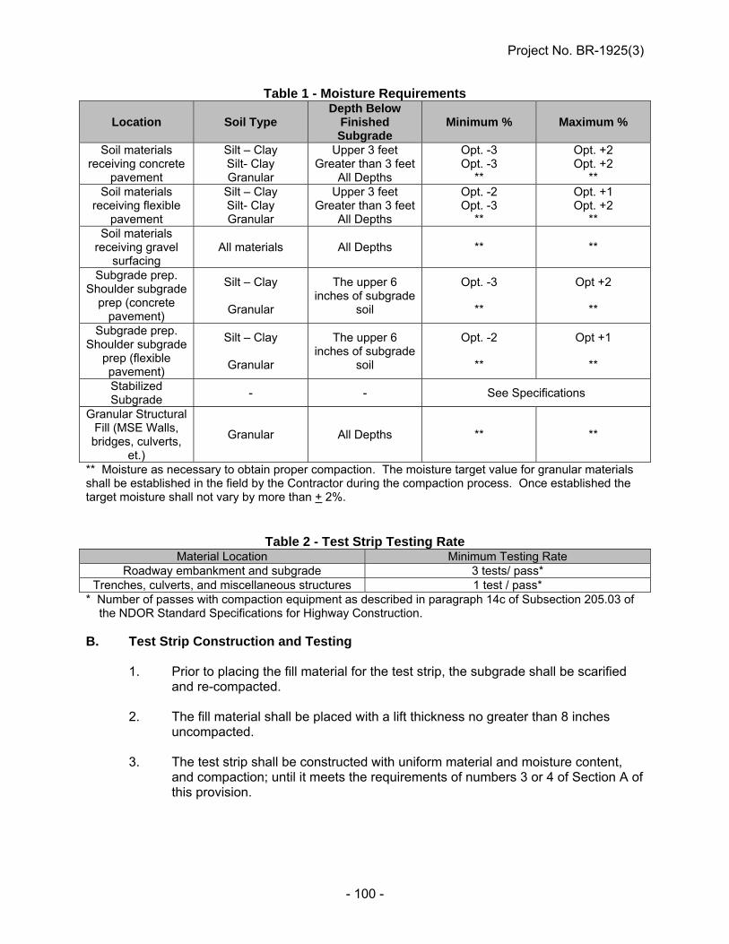
Project No. BR-1925(3)
- 100 -
Table 1 - Moisture Requirements
Location Soil Type Depth Below
Finished Subgrade
Minimum % Maximum %
Soil materials receiving concrete
pavement
Silt – Clay Silt- Clay Granular
Upper 3 feet Greater than 3 feet
All Depths
Opt. -3 Opt. -3
**
Opt. +2 Opt. +2
** Soil materials
receiving flexible pavement
Silt – Clay Silt- Clay Granular
Upper 3 feet Greater than 3 feet
All Depths
Opt. -2 Opt. -3
**
Opt. +1 Opt. +2
** Soil materials
receiving gravel surfacing
All materials All Depths ** **
Subgrade prep. Shoulder subgrade
prep (concrete pavement)
Silt – Clay
Granular
The upper 6 inches of subgrade
soil
Opt. -3
**
Opt +2
**
Subgrade prep. Shoulder subgrade
prep (flexible pavement)
Silt – Clay
Granular
The upper 6 inches of subgrade
soil
Opt. -2
**
Opt +1
**
Stabilized Subgrade
- - See Specifications
Granular Structural Fill (MSE Walls, bridges, culverts,
et.)
Granular All Depths ** **
** Moisture as necessary to obtain proper compaction. The moisture target value for granular materials shall be established in the field by the Contractor during the compaction process. Once established the target moisture shall not vary by more than + 2%.
Table 2 - Test Strip Testing Rate Material Location Minimum Testing Rate
Roadway embankment and subgrade 3 tests/ pass* Trenches, culverts, and miscellaneous structures 1 test / pass*
* Number of passes with compaction equipment as described in paragraph 14c of Subsection 205.03 of the NDOR Standard Specifications for Highway Construction. B. Test Strip Construction and Testing 1. Prior to placing the fill material for the test strip, the subgrade shall be scarified
and re-compacted. 2. The fill material shall be placed with a lift thickness no greater than 8 inches
uncompacted. 3. The test strip shall be constructed with uniform material and moisture content,
and compaction; until it meets the requirements of numbers 3 or 4 of Section A of this provision.
Project No. BR-1925(3)
- 101 -
4. The deflection target value is obtained when: i. The moisture content is within the acceptable range.
ii. The average of the deflection test measurements for three consecutive passes of compaction equipment does not change by more than 10% with additional compaction. The DTV shall be based on the lowest average deflection test measurement from these passes.
5. A 10-lb sample of the test strip material shall be submitted to the NDOR Branch
Lab or Materials and Research Soil Lab for index testing. 6. The DTV shall be re-evaluated when: i. Deflection test measurements are consistently less than the DTV. (3 out
of 5 consecutive deflection test measurements are less than 0.80 of the DTV).
ii. Failing test results are consistently occurring and adequate compaction is observed.
Option 2 C. Determination of Deflection Target Values based on the Nebraska Group Index
(NGI) 1. Prior to construction a 10-lb bag of representative material shall be submitted to
the nearest NDOR Branch Lab or Materials and Research Soil Lab for each different soil type no less than 21 days prior to grading operations.
2. From the laboratory testing NDOR will determine the Nebraska Group Index
(NGI) for each soil type submitted and provide a correlated minimum DTV and optimum moisture content.
3. If no correlation data is available for an individual NGI, a test strip shall be used
to determine the DTV as discussed in parts A and B in this provision. 4. The DTV shall be re-evaluated when: i. Deflection test measurements are consistently less than the DTV. (More
than 20% of the deflection test measurements are less than 0.80 of the DTV.
ii. Failing test results are consistently occurring and adequate compaction is observed.
Project No. BR-1925(3)
- 102 -
Acceptance Testing 1. The Deflection Target Value for use as acceptance testing shall be: DTV ≤ 1.10 x average deflection value determined from Option 1, Part B,
of this provision
DTV ≤ Correlated DTV determined from the NGI correlation, Option 2, Part C
2. The testing frequency for moisture and deflection shall follow the NDOR
Materials Sampling Guide. 3. The moisture content of soil shall be performed using NDOR’s approved
equipment and methods. Approved equipment includes: 1) hot plates, stove, or microwave, 2) Speedy Moisture Method, or 3) Laboratory oven method.
4. Moisture content results shall be reported to the nearest tenth of a percent.
SUBGRADE PREPARATION (C-1-0307)
Paragraph 2.a. of Subsection 302.03 in the Standard Specifications is amended to include that trimming on narrow, irregular or roadway grading of 1/2 mile (0.8 km) or less may be accomplished using conventional methods.
TYPE B HIGH INTENSITY WARNING LIGHTS (D-6-0307)
All references in the plans to Type B High Intensity Warning Lights shall be considered void. The plans will not be revised to reflect this change.
TEMPORARY TRAFFIC CONTROL DEVICES (Type II Barricades, Reflectorized Drums, 42" (1070 mm) Reflective Cones, and
Vertical Panels) (D-6-1112)
Paragraph 2.d. of Subsection 422.03 in the Standard Specifications is void and superseded by the following:
d. (1) Reflectorized drums used for traffic warning or channelization shall be constructed of lightweight, flexible, and deformable materials, be a minimum of 36 inches (900 mm) in height, and have a minimum width of 18 inches (450 mm), regardless of orientation. The predominant color of the drum shall be orange.
(2) Steel drums shall not be used.
Project No. BR-1925(3)
- 103 -
(3) The markings on drums shall be horizontal, shall be circumferential, and shall display four 6-inch (150 mm) wide bands of retroreflective sheeting, alternating fluorescent orange - white – fluorescent orange - white. The fluorescent orange sheeting shall meet the luminance requirements of the following table.
FHWA Luminance Factor
Luminance Factor YT
Sheeting Type Min Max Fluorescence Luminance
Factor Limit, YF Fluorescent Orange 25 None 15
e. When approved by the Engineer or shown in the plans, 42" (1070 mm) reflective
cones may be used in lieu of Type II Barricades or Reflectorized Drums. 42" (1070 mm) reflective cones shall include a 30-pound (14 kg) rubber base and display four 6-inch (150 mm) wide bands of retroreflective sheeting, alternating fluorescent orange - white - fluorescent orange - white. 42" (1070 mm) reflective cones shall not be used for lane-closure tapers or shifts.
f. Rubber base-mounted 36-inch vertical panels shall not be used for
channelization when the speed limit exceeds 40 miles per hour. Paragraph 2.b. of Subsection 422.04 of the Standard Specifications is void and superseded by the following:
b. (i) Type II Barricades, Reflectorized Drums, and 42" (1070 mm) Reflective Cones shall be counted as "Barricades, Type II" and measured for payment by the number of calendar days each is in place and positioned as shown in the plans or as directed by the Engineer.
(ii) Vertical Panels shall be measured for payment as permanent "Sign Days" (by the
each) by the number of calendar days each vertical panel unit is in place and positioned as shown in the plans or as directed by the Engineer.
Paragraph 2.c. of Subsection 422.04 of the Standard Specifications is amended to include Reflectorized Drums. Paragraphs 3. and 4. of Subsection 422.05 of the Standard Specifications are void and superseded by the following: 3. a. The pay item "Barricade, Type II" is used to pay for three items ("Barricades,
Type II", "42" (1070 mm) Reflectorized Cones", and "Reflectorized Drums"). b. "Barricades, Type II", which includes "42" (1070 mm) Reflectorized Cones", and
"Reflectorized Drums", is paid for as an "established" contract unit price item. The established unit price is identified on the "Schedule of Items" shown in the Proposal.
4. Payment for vertical panels includes all posts, brackets, or hardware necessary
to install and maintain the vertical panel units.
Project No. BR-1925(3)
- 104 -
WORK ZONE TRAFFIC CONTROL SIGNS (D-6-1212)
The Department has adopted the FHWA 2009 Manual of Uniform Traffic Control (MUTCD) and the 2011 Nebraska Supplement to the MUTCD as the official guidance for work zone traffic control signs. Many work zone traffic control signs have been revised, redesigned, or replaced in the 2009 MUTCD (and 2011 Nebraska Supplement). Accordingly, all work zone signs shall comply with the following: 1 - All signs, regardless of age, shall meet the design standards of the 2009 MUTCD
(and 2011 Nebraska Supplement).
TEMPORARY TRAFFIC CONTROL FOR PERMANENT PAVEMENT MARKING (D-13-1007)
Paragraph 4. of Subsection 423.04 in the Standard Specifications is void.
CONCRETE PAVEMENT CORING (F-17-0110)
Paragraphs 3. a. and 3.b. of Subsection 603.05 of the Standard Specifications are void and superseded by the following:
3. a. (1) A pay factor will be applied to each unit based on the compressive strength of 1 core per unit tested in accordance with AASHTO T 24.
(2) Concrete cores must have a minimum age of 28 days before testing. (3) The paved area shall be divided into units, and each unit will be considered
separately. (4) Units are 750 linear feet (230 m) of pavement for each separately placed width
or width of each class of concrete whether or not placed separately starting at the beginning of the pavement.
b. (1) When any unit core fails to have the required minimum compressive strength,
the Contractor will have the option to obtain, at no cost to the Department, two additional cores from that unit provided that:
(i) The cores shall be cut by the Contractor (the cutting to be witnessed by
the Engineer) (ii) The cores shall be cut within seven (7) days of being notified of the
strength deficiency, and (iii) The cores shall be cut within 6 inches of the original unit core in the
longitudinal direction.
(2) The Engineer will take possession of the cores and have them tested within 24 hours at the Materials and Research laboratory.
Project No. BR-1925(3)
- 105 -
(3) The results of all three cores sampled at the location will be averaged for the final compressive strength calculation and pay factor.
(4) The Department may agree to cut the additional cores if requested to do so by
the Contractor, but will do so only if the Department's coring crew is available on the project and has sufficient time to cut and transport the cores for testing during normal working hours within seven (7) days of the Contractor being notified of the strength deficiency.
Paragraph 4.a.(4) of Section 603.05 in the Standard Specifications is void and replaced by the following: A separately placed width is the width between field constructed longitudinal joints,
between a longitudinal construction joint and the edge, or between two pavement edges. A separately placed width may include more than one pay class of concrete, such as doweled and non-doweled.
PORTLAND CEMENT CONCRETE PAVEMENTS GENERAL REQUIREMENTS
(F-20-0611) Paragraph 7.b. of Subsection 601.02 in the Standard Specifications is void and superseded by the following:
b. The finishing machine shall travel at a controlled speed such that it produces a uniform, well consolidated pavement that does not contain large voids.
Paragraph 10.d. of Subsection 601.02 is void and superseded by the following:
d. The Contractor shall always have a tachometer available to monitor vibrator
frequency. The vibrator frequency shall be within the manufacturer’s specifications not to exceed 9,000 vpm.
Paragraph 12.d.(1) of Subsection 601.02 is void and superseded by the following: (1) The mechanical joint saw shall have an adjustable guide to insure a true line is
cut. The mechanical joint saw blade shall be water-cooled, or specifically designed for early-entry sawing if air cooled.
Paragraph 12.d.(2) of Subsection 601.02 is void. Paragraph 12.d.(3) of Subsection 601.02 is void and superseded by the following:
d. (3) The joint cut shall be made with a diamond-toothed blade.

Project No. BR-1925(3)
- 106 -
CONCRETE PAVEMENT (F-21-0516)
Paragraph 2.a. of Subsection 603.03 in the Standard Specifications is amended to include the following: (6) The base material shall be moistened through a uniform, lightly applied spray
pattern prior to concrete placement as directed by the Engineer. Paragraphs 2.d. and e. of Subsection 603.03 are void and superseded by the following: d. After being consolidated with internal mechanical vibration, the concrete shall be
struck off to a uniform height approximately 0.5 inch (12 mm) above the finished surface and then finished to the final elevation by means of a vibrating mechanical or vibrating hand operated screed.
e. Finished concrete shall be of uniform density with no segregation,
honeycombing, or large voids. Paragraph 3.f. of Subsection 603.03 is void and superseded by the following: f. (1) A wet burlap, carpet, or canvas drag will be drawn over the entire surface in a
longitudinal direction for a final finish, dampening of this drag material will be accomplished through a uniform, lightly applied spray pattern.
(2) The drag shall be suspended from a mandrel, or similar device, to insure a
uniform texture. (3) The drag shall be lifted from the surface of the concrete pavement when the
paving train is not in motion for 30 minutes or more and carefully reset before resuming the dragging operations.
(4) Drags shall be rinsed or washed as necessary to obtain a uniform surface.
Drags that cannot be cleaned shall be replaced. Paragraphs 4.e., f., g., and h. of Subsection 603.03 are void and superseded by the following: e. For areas with pavement widening, dowel baskets shall be placed in all
transverse contraction joints which are 6 feet (1.8 mm) or wider. f. If normal vibration is found inadequate to thoroughly consolidate the plastic
concrete within and around the dowel basket assemblies, adjustments to the material and/or operations shall be made.
g. Precautions shall be taken to assure that the sawed contraction joint is located
directly over the center of the dowel bars. h. Transverse cracks which form in the concrete pavement panels between load
transfer joints shall be stitched as shown in the plans, described in the Special Provision or repaired as directed by the Engineer. No payment will be made for this work.
Project No. BR-1925(3)
- 107 -
Paragraph 6.b.(7)(i) of Subsection 603.03 is void and superseded by the following: (7) (i) The concrete shall be textured by dragging a wet burlap, carpet, or canvas belt
over the full width of the surface in a longitudinal direction. Dampening of this drag material will be accomplished through a uniform, lightly applied spray pattern.
Paragraph 6.c.(4)(i) of Subsection 603.03 is void and superseded by the following: (4) (i) The concrete shall be textured by dragging a wet burlap, carpet, or canvas belt
over the full width of the surface in a longitudinal direction. Dampening of this drag material will be accomplished through a uniform, lightly applied spray pattern.
Paragraph 7.a.(3) of Subsection 603.03 is void and superseded by the following: (3) (i) The curing compound shall be applied in 2 equal applications immediately
following each other or other methods approved by the Engineer. (ii) The total rate of applications shall be at a minimum of 1 Gal/100 SF (0.3 L/m2) of
surface area for tined surfaces or 1 Gal/150 SF (0.2 L/m2) of surface area for all other finishes.
Paragraph 8.a.(6) of Subsection 603.03 is voided and superseded by the following: (6) Any panels that contain random cracking will be considered unacceptable. The
Engineer will decide whether to replace or repair the panel. The Contractor shall replace or repair these panels at the direction of the Engineer at no cost to the Department. A 20% deduction will be assessed on any repaired panel. Any panel that is replaced will not be assessed a 20% deduction.
Paragraph 8.d.(3) of Subsection 603.03 is void. Paragraphs 8.d.(4), (5) and (6) of Subsection 603.03 are void and superseded by the following: (4) Before sealing, the joint wall (not the bottom of joint) surfaces shall be
sandblasted or water-blasted to remove all dirt, curing compound residue, laitance, and any other foreign material. After sandblasting, the entire joint shall be cleaned with compressed air having a minimum pressure of 90 psi (620 kPa). The compressed air shall be free of oil, water, and other contaminants. The joints shall be dry at the time of sealing.
(5) (i) Transverse contraction joints in Portland cement concrete pavements shall be
sealed so that the joint is filled to approximately 1/8” to 3/8” (3 to 9 mm) below the top of the joint with an approved hot poured sealant.
(ii) All overflow material shall be removed from the surface of the pavement. (iii) If adhesion is not satisfactory, the material shall be rejected. (6) The Contractor shall give the Engineer one copy of the hot pour manufacturer’s
sealing recommendations.
Project No. BR-1925(3)
- 108 -
Paragraph 9.b. of Subsection 603.03 in the 2007 edition of the NDOR Standard Specifications for Highway Construction is void and superseded by: b. When the pay item “Portland Cement Concrete Smoothness Testing” is not
included in the contract, the Contractor shall test the hardened concrete for surface irregularities with a California Profilograph. Areas showing high spots (bumps) in excess of 0.30 inches in a 25 foot span will be plainly marked on the pavement and on the printed pavement profile trace. All identified high spots shall be ground to the required profile. The grinding shall be performed so that the cement-aggregate bond is not broken. The equipment and profilograph test procedure requirements of Section 602 of the Standard Specifications for Highway Construction shall apply to this surface testing.
Paragraph 9.c of Subsection 603.03 is amended to include: c. At the Engineer’s option, the use of a 10 foot straightedge to locate high spots in
excess of 1/8 inch may be allowed in lieu of bump detection using a profilograph testing.
Paragraphs 11.c., d. and e. of Subsection 603.03 are void and superseded by the following:
c. The Contractor’s forces may be allowed on the concrete pavement when the concrete has reached a minimum age of 14 days or when the concrete has reached a compressive strength of 3000 psi (24 MPa) when tested in accordance with ASTM C 39.
d. With the approval of the Engineer, the Contractor may elect to increase the early
strength of the concrete by adding cement and/or reducing the water/cement ratio, and then the pavement may be opened to traffic provided it has attained a compressive strength of 3500 psi (24 MPa). The concrete in the area where the early strength is required shall be paid for at the bid price.
e. When required by the Special Provisions or when requested by the Contractor,
the maturity method, as provided for in ASTM C 1074, may be used in lieu of the requirements of Subsection 603.03, Paragraph 10.c. and d. to determine the strength of concrete pavement for the purpose of early opening to traffic. Requests by the Contractor for use of the maturity method shall be on a project basis and shall be made in writing to the Materials and Research Engineer. The Contractor shall be responsible to coordinate with the Materials & Research Division to develop the maturity curve.
Paragraph 3.a. and b. of Subsection 603.05 is void and superseded by the following:
3. a. A pay factor will be applied to each unit based on the compressive strength of 1 core per unit tested in accordance with AASHTO T 24. Concrete cores must have a minimum age of 28 days before testing. The Contractor will have the option to obtain two additional cores for any unit core that fail to have the required minimum compressive strength provided that the cores are:
(1) Obtained and tested within seven (7) days of being notified of the strength
deficiency, under the supervision of the Engineer. (2) Cut within 6 inches of the original unit core in the longitudinal direction.

Project No. BR-1925(3)
- 109 -
The results of all three cores sampled at the location will be averaged for the final compressive strength calculation and pay factor.
b. The paved area shall be divided into units. Each unit will be considered separately. Units are 750 linear feet (230 m) of pavement for each separately placed width, or width of each class of concrete whether or not placed separately starting at the beginning of the pavement.
Paragraph 4.a.(4) of Subsection 603.05 in the Standard Specifications is void and replaced by the following: A separately placed width is the width between field constructed longitudinal joints,
between a longitudinal construction joint and the edge, or between two pavement edges. A separately placed width may include more than one pay class of concrete, such as doweled and non-doweled.
Paragraph 4.a.(7) of Subsection 603.05 is void and superseded by the following: (7) A the option of the Engineer, cores may not be required from irregular areas with
widths less than 8 feet (2.4 m) or from an individual pavement type that involve less than 5,000 square yards (4200 m2) of pavement.
Paragraph 4.c.(4) of Subsection 603.05 is void and superseded by the following: (4) If the average thickness of the cores is deficient by more than 0.25 inch (6 mm)
but not more than 0.50 inch (12.5 mm) an adjusted unit price will be paid in accordance with Table 603.04. Cores deficient by more than 0.50 inch (12.5 mm) will be treated as prescribed in Paragraph 4.d. of this Subsection.
CONCRETE CONSTRUCTION (G-5-1015)
Section 704 in the Standard Specifications is amended to include the following: All concrete rails on bridges and approach slabs shall be cast-in-place. Slip-forming will
not be permitted for concrete rails on bridges and approach slabs. Paragraph 8. of Subsection 704.03 is amended to provide that forms for 42 inch bridge rails shall be made of steel. Wood forms that are commercially manufactured to the specific shape of the 42 inch rail shall be permitted. Forms shall be capable of producing a uniform surface, texture and appearance equal to that obtained by using steel panels in good condition. The fourth subparagraph of Paragraph 8.j. of Subsection 704.03 is void and superseded by the following:
Steel stay-in-place form material shall conform to the requirements of ASTM A 653/A 653M Coating Designation G165/Z500.

Project No. BR-1925(3)
- 110 -
Paragraphs 8.a., b. and c. of Subsection 704.05 are void and superseded by the following: 8. Payment Deductions:
a. The 28-day compressive strength is determined by the average strength of all cylinders made on a specific day to determine the 28-day compressive strength of all of a group’s class of concrete poured that day. Concrete with a 28-day compressive strength not meeting the design compressive strength is subject to removal.
b. If the 28-day compressive strength is less than the design compressive
strength, cores may be taken, at the discretion of the Engineer, within 45 days after the concrete was poured. The average of the cores will be used to determine the compressive strength.
c. If either the 28-day compressive strength or the average core strength is
less than the design strength and the Engineer determines that the concrete is acceptable for use, the concrete is subject to a payment deduction. The pay deduction is shown below:
2 x (Design Compressive Strength – 28-day Compressive Strength) = Percent Reduction
Design Compressive Strength
Or 2 x (Design Compressive Strength – Average Core Compressive Strength) = Percent Reduction
Design Compressive Strength
CONCRETE BRIDGE FLOORS (10-DAY WET CURE)
(G-5-0916) The following Special Provision applies to concrete decks and approaches on girder and slab bridges for new bridges and complete deck replacements. Bridge deck widenings, partial deck replacements, and deck and joint repairs shall be cured in accordance with Section 706 of the specifications. Approaches that are not part of a new bridge or complete deck replacement shall be cured in accordance with Section 706 of the specifications. Paragraph 8.i of Subsection 704.03 in the Standard Specifications is amended to include the following: 8.i.(4) Reinforcing steel and form work for bridge curbs and bridge rails shall not be
placed until after the 10-day wet curing. Paragraph 14 of Subsection 704.03 in the Standard Specifications is void and superseded by the following: 14. Bridge Deck Curing in Cold Weather a. The following requirements shall govern the placement of bridge deck
concrete when the temperature will be less than 40⁰F during the 10-day wet curing period.
Project No. BR-1925(3)
- 111 -
(1) The temperature of the concrete shall not be less than 50⁰F immediately after being placed.
(2) The Contractor shall furnish heating equipment and/or enclose and protect the structure in such a way that the concrete shall be maintained at a temperature between 50⁰F and 100⁰F for the first 72 hours after the concrete has been placed, and at a temperature of between 40⁰F and 100⁰F for the next 168 hours.
(3) After 240 hours of curing is complete, the concrete temperature shall not decrease at a rate faster than 5⁰F/hour.
b. The Contractor shall assume all risk connected with the placing of
concrete during freezing weather, and permission given by the Engineer to place concrete during such time will not relieve the Contractor of the responsibility for satisfactory results. Any concrete showing damage from freezing shall be rejected.
Paragraph 5 of Subsection 706.03 in the Standard Specifications is void and superseded by the following: 5. No work shall be performed on the bridge deck, including forming and placing
reinforcement for concrete curbs or railing until the concrete deck has cured for 10 days. Only equipment necessary for forming and pouring the bridge rail shall be allowed on the deck during the 7 days of white pigment curing.
Paragraphs 8, 9, and 10 of Subsection 706.03 in the Standard Specifications are void and superseded by the following: 8. a. Finishing (1) Immediately following the finishing machine, the Contractor shall give the
bridge floor surface a drag finish with wet burlap, carpet or a soft bristled broom. The drag finish shall create a uniform, fine-grained finish on the sealed concrete surface.
b. Grooving (1) Transverse tining in plastic concrete of bridge decks (and approaches on
new bridges and bridge deck replacements) will not be allowed unless otherwise stated in the contract documents.
(2) The Contractor shall cut longitudinal grooves into hardened concrete
surfaces using a mechanical cutting device. The Contractor shall perform longitudinal grooving after surface correction grinding.

Project No. BR-1925(3)
- 112 -
(3) The longitudinal grooves shall be: (i) 1/8 inch ± 1/64 inch wide,
(ii) 1/8 inch to 1/4 inch (3 mm to 6 mm) deep, and
(iii) Uniformly spaced at 3/4 inch intervals measured center to center of groove.
(4) Longitudinal grooving shall include both bridge and paving approaches.
Grooving shall terminate approximately 6 inches (150 mm) from bridge expansion joints.
(5) Longitudinal grooving on the bridge deck and approach sections shall be
discontinued 3 feet from the bridge curb, rail, raised medians, or barriers unless otherwise indicated on the plans.
(6) For phased bridge and bridge approach construction: (i) The Contractor may cut longitudinal grooves in the hardened
concrete at the end of each phase of construction or wait until all phases have been completed. If the Contractor elects to delay cutting of the longitudinal grooves until completion of all phases, apply an interim broom finish on the concrete deck and bridge approach during placement for all phases opened to traffic.
(ii) The Contractor shall finish all longitudinal grooving for all phases within 30 calendar days following completion of the last phase of the bridge.
(iii) The interim broom finish will not be allowed as a surface texture when opened to traffic over a winter season. If the interim broom texture is present and the Contractor is not in a position to finish all phases of the bridge, the Contractor shall cut longitudinal grooving into the hardened concrete in order to establish an acceptable driving surface texture for the winter season.
(7) Grooves shall be constructed using multi-blade saw cutting equipment,
fitted with diamond-tipped circular saw blades. Before grooving operations, two approved gauges to verify groove depth
shall be supplied. The gauges shall be accompanied by the manufacturer’s instructions for their use.
During grooving operations, the groove dimensions will be checked at
random. If the minimum groove depth has not been achieved, grooving operations shall stop and the necessary adjustments shall be made.
(8) Sidewalks and top of curbs shall not be grooved and shall receive a final
finish with a fine – bristle broom.

Project No. BR-1925(3)
- 113 -
9. Curing a. For this Specification, the bridge deck is defined as the concrete deck and
pavement cast between the bridge grade beams. Approaches outside the grade beams are excluded.
b. The Contractor shall cure the concrete deck with wet burlap for at least
240 hours. Burlap with Polyethylene backing will not be allowed on decks unless allowed by the Engineer.
(1) The Contractor shall place uniformly saturated wet burlap on the
concrete no later than 20 minutes after the finishing machine passes.
(2) The burlap shall be thoroughly wetted prior to placing it on the concrete. The burlap shall be kept continuously wet by means of a sprinkling or wetting system for the 10 days.
(3) The wet burlap shall be secured or weighed down so that it remains in contact with the concrete surface.
(4) After 96 hours, the Contractor may place white opaque polyethylene film over the wet burlap to reduce the amount of water needed.
c. After the 10 day wet cure, the Contractor shall apply an approved white
pigment curing compound within 45 minutes of removing the wet burlap. (1) The total rate of combined applications shall be a minimum of 1
Gal/150 SF of surface area.
(2) The Contractor shall cure the deck with the white pigment curing membrane for an additional 7 days. The Contractor may work on the bridge concrete rail during the 7 days provided caution is used to limit damage to the membrane.
(3) Curing compound shall not be applied to construction joints or reinforcing steel.
d. The Contractor must provide a list of equipment, equipment certification,
and the number of personnel that will be dedicated to the curing operation at least 24 hours before the actual casting date.
e. The Contractor shall be responsible for the repair of all visible cracks
more than 3 inches (75 mm) in length that develop on the bridge deck up to the time the project is accepted at no additional cost to the Department.
f. Cracks shall be repaired with an approved bridge deck crack sealant
(methacrylate). Crack sealants shall be installed in accordance with the manufacturer’s recommendations.
g. Concrete Bridge curbs and rails shall be cured in accordance with
Subsection 704.03.

Project No. BR-1925(3)
- 114 -
10. Grinding a. The grinding and grooving shall not be done until after the 17 days of
curing is complete. b. Bridge decks shall be ground for smoothness in accordance with
Section 733. (1) For bridge decks and approaches that are not covered by
Section 733: i. The Contractor shall test the cured concrete for surface
irregularities with either a 10 foot straightedge placed or operated parallel to the centerline of the roadway or some other device for measuring deviations from a plane. Variations greater than 1/8th inch shall be plainly marked for removal, except that for decks which are to receive a subsequent overlay course greater than 1 inch thick, where ¼ inch variations are allowed.
ii. The Contractor shall grind or cut irregularities that exceed the above limits. Bush hammering or other impact methods are not allowed.
Paragraph 15 of Subsection 706.03 in the Standard Specifications is void and superseded by the following: 15. Time for Opening Bridge Floor to Traffic a. The Contractor shall not open the bridge floor to traffic until approval has
been given by the Engineer. The Engineer may open the bridge when the concrete has reached a minimum age of 17 days and has developed a compressive strength of at least 3500 psi.
b. Construction equipment will not be allowed on the deck until after the 10 day wet curing period. Vehicles needed for construction activities and weighing less than 4.0 kips, and comparable materials and equipment loads, shall be allowed on any span only after the last placed deck concrete has attained a compressive strength of at least 2.4 ksi. Loads in excess of the above shall not be carried on bridge decks until the deck concrete has reached 80% of the minimum compressive strength prescribed elsewhere in these Special Provisions and after the 10 days wet curing period.
Paragraph 1 of Subsection 706.05 in the Standard Specifications is amended to include the following: 1. Pay Item Pay Unit Bridge Deck Grooving Square Yards (SY)

Project No. BR-1925(3)
- 115 -
PILES AND PILE DRIVING (G-6-1014)
Paragraph 1.m.(1) of Subsection 703.03 of the Standard Specifications for Highway Construction is void and superseded by the following: All welding to be done on steel piles shall be in accordance with the plans and the
applicable requirements of Section 708 in the Standard Specifications. Welder qualification certification is required and must be submitted to the Bridge Fabrication Manager for approval prior to any welding.
All field welding on steel piles shall be done in the SMAW process using
electrode E7018. For bridges with design live load “HL-93”, the tables in paragraph 4.c. of
Subsection 703.03 (on pages 444 and 445) in the Standard Specifications are void and superseded by the following:
Dynamic Formulas (English and Metric)
Diesel Hammers:
P = 4.0 E S+0.5
For all piles driven from the top with a single-acting diesel hammers (English)
P = 3.27 E S+12.7
For all piles driven from the top with a single-acting diesel hammers (Metric)
Where:
P = the bearing capacity, in kips (English) or kN (Metric)
W = the mass of the ram, in kips (English) or kg (Metric)
M = the mass of the pile and driving cap, in kips (English) or kg (Metric)
S = the average penetration per blow, in inches (English) or millimeters (Metric), of the last 10 blows for diesel hammers
H = the height of fall of the ram, in feet (English) or meters (Metric) (less twice the height of bounce for gravity and steam hammers)
E = the energy per blow in foot-kips (English) or meter-kilogram (Metric). For single-acting diesel hammers, E = W x H
Unless permitted by the NDR Geotechnical Section, all piles driven with hammers other than single-acting diesel hammers shall be tested with the Pile Driving Analyzer to verify capacity.
P = 4.9 WH S+0.35
X W W+M
For gravity hammers
P = 4.9 E S+0.1
X W W+M
For steam hammers
P = 2.2 E S+0.1
For driving mandrel driven pile shells

Project No. BR-1925(3)
- 116 -
Paragraph 7.a. of Subsection 703.03 is void and superseded by the following: a. “Practical Refusal” occurs when actual bearing capacity is 2.0 times the Design
Pile Bearing. Paragraph 2. of Subsection 703.05 is void and superseded by the following: 2. a. (1) Provided that the Contractor furnishes the Engineer signed purchase
orders for bearing and sheet piling, authorized “cutoff” of bearing and sheet piling shall be made at the invoice price per linear foot (meter) of bearing piling, and per square foot (meter) of sheet piling.
(2) The signed purchase orders shall be furnished at the pre-construction conference.
b. In those cases where signed purchase orders for bearing and sheet piling are not
furnished at the pre-construction conference, authorized “cutoff” of bearing and sheet piling shall be made at 60 percent of the piling's contract unit price.
c. No payment is made for "cutoff' beyond the order length. d. When bearing or sheet pile are authorized for cutoff and are suitable for use as
spliced material for the same purpose on the project, the length of material subsequently driven as service piling shall be deducted from the payment for cutoff. No piece of piling can qualify for more than one measurement as pay cutoff.
Paragraph 3. of Subsection 703.05 is void and superseded by the following: 3. Splices ordered by the Engineer shall be paid for at 5 times the unit bid price
(2 times the unit bid price for Metric projects) for HP steel piling, pipe, piling, and cast-in-place piling; and at 20 times the unit bid price (7 times the unit bid price for Metric projects) for driving and build-up splices for precast/prestressed concrete piling.
REINFORCING STEEL SUPPORTS (G-8-1114)
Paragraph 3.b.(2) of Subsection 707.03 of the Standard Specifications is void and superseded by the following: Reinforcing steel in concrete decks and slabs shall be positioned on plastic coated
supports or chairs to accurately maintain the specified clearance to the surface of the concrete. Supports shall be spaced at distances not greater than 3 feet for #4 top bars or 4 feet for all other reinforcing.

Project No. BR-1925(3)
- 117 -
PILE CUTOFF ELEVATIONS (G-9-0508)
Table 203.01 of the Standard Specifications is void and superseded by the following:
Table 203.01 – Pile Cutoff Elevation
Excavation or Embankment Areas 2 feet (600 mm) below finished grade
Stream Channels (between high banks) 2 feet (600 mm) below defined flowline elevation
All other areas 2 feet (600 mm) below natural ground
CONTRACTOR’S ACCESS CROSSING
It will be the Contractor’s option to use an access crossing to construct the bridge on this project. Bidders must submit a bid for the item “Access Crossing ___” in the schedule of items. The item “Access Crossing ___” will be paid for as a lump sum. The bid price shall be considered full compensation for all work required for the Contractor to construct and remove the access crossing. The Contractor will only be paid for this item if they construct the access crossing. The Contractor will be paid 90% of the lump sum when the access crossing is installed. The remaining 10% of the lump sum will be paid when the access crossing is removed. If the Contractor does not plan to utilize an access crossing, they shall bid the item “Access Crossing ___” at 0$. If the Contractor bids this item at 0$ and later decides to utilize an access crossing, it will be at the Contractor’s expense. No change orders will be approved to increase the cost of the “Access Crossing ___” item after award of the contract.
Project No. BR-1925(3)
- 118 -
SPECIAL PROVISIONS Water Main, Valves, Hydrants and Appurtenances 3.00 SCOPE - This specification is intended to define and/or limit the required quality standards of the materials furnished and the workmanship performed in connection with the herein specified items of piping, fittings, valves and hydrants with all the required accessories and/or appurtenances, including in part; all labor, tools, materials and equipment for the complete work of this project which are in accordance with this specification and the applicable drawings. 3.10 GENERAL - The Contractor shall remove paving, as may be required, excavate the trenches and pits to the required dimensions; excavate the bell holes; construct and maintain all bridges for traffic control; sheet, brace and support the adjoining ground or structures where necessary; handle all drainage or groundwater; provide barricades guards and warning lights; lay and test the pipe, castings, fittings, valves, hydrants and accessories; backfill and consolidate the trenches and pits; restore the roadway surface unless otherwise stipulated; supply required or remove surplus excavated material; and clean the site of the work. The latest revisions of the standards referred to herein existing at the time of the bid opening shall prevail. Although such work is not specifically shown or specified, all supplementary or miscellaneous items, appurtenances and devices incidental to or necessary for a sound, secure, complete and compatible installation shall be furnished and installed as part of this work. The Drawings show sizes and general arrangements of all pipes and appurtenances. Responsibility for handling and/or cutting exact lengths of the various sizes of pipe for proper make-up rests with the Contractor. The work shall comply with the current requirements of the American Water Works Association (AWWA) at the time of the Bid opening. Water distribution system installation must comply with State of Nebraska Department of Health and Human Services Standards. All chemicals utilized for water main construction shall be NSF 60 approved, and all materials shall be NSF 61 approved. 3.20 MATERIALS 3.21 WATER MAIN MATERIAL 3.21a POLYVINYL CHLORIDE (PVC) PLASTIC PIPE - The pipe shall meet the requirements of AWWA Standard Specification C900 and C900 RJ (Restrained Joint), with a dimension ratio of 18. The pipe shall be joined by means of a rubber gasket-integral bell joint. Gaskets will conform to the requirements of ASTM F-477. Joints for plastic pressure pipes shall conform to ASTM D-3139 using flexible elastomeric seals. All pipe shall have a gasket bell section or coupling at least as strong as the pipe wall. The outside pipe diameters shall be cast iron pipe equivalent. Pipe lengths shall be nominal 20 ft. (6.10 m). If pipe is to be stored for periods longer than 90 days, the pipe must be covered in a manner approved by the Engineer. Install pipe in accordance with manufacturer’s recommendations.

Project No. BR-1925(3)
- 119 -
3.22 WATER MAIN LOCATING WIRE – The Contractor shall install 12 gauge coated Tracer Wire attached to the water main during installation. No separate payment will be made for the installation of the wire but shall be considered incidental to the water main installation. The tracer wire shall be copper wire or copper clad steel wire with a minimum of 30 mil polyethylene coated jacket, which shall be laid on top of and along entire length of all new pipes and shall be extended to the surface at all valve locations and fire hydrants. Tracer wire shall be Copperhead CCS high strength or pro-trace HD-CCS PE45. For termination, tracer wire shall extend into a junction box which is designed for tracer wire termination with surface connectors with blue top color. Fasten the wire to the top of the pipe so as not to be displaced by backfilling procedure (one method of accomplishing this is to affix the wire to the top of the pipe with duct tape at approximately 10 feet intervals). Connections to new wire spools or splices shall be made with a direct bury lug or silicon filled twist connectors. Tracer wires shall be tested to verify if water main can be located. All wires failing to provide location shall be repaired or replaced at the Contractor’s expense. This item is incidental to water main installation unit bid price 3.24 FITTINGS - Fittings shall be mechanical joint conforming to AWWA Standard Specification C-153, C-104 and C-111. Fittings shall be formed from ductile iron and rated for 350 psi working pressure. Caps, plugs and miscellaneous fitting shall be provided conforming to AWWA Standard Specification C-110. Bolts and nuts shall be carbon and alloy steel conforming to ASTM A194. 3.25 FIRE HYDRANTS - Hydrants furnished shall conform to the requirements of the AWWA Standard Specification C-502. Hydrants shall open to the left (counter-clockwise) unless otherwise specified. Hydrants shall be designed to operate under 150 psi (10.5 kg/sq. cm) working pressure and tested at 300 psi (21.0 kg/sq. cm). All fire hydrants shall be red. All water passages shall be of such form and size as to permit the full flow of water without undue loss by friction. Hydrants must have a positive drain, which will allow the water to escape readily from the standpipe when the hydrant valve is closed, but said drain opening must be closed as soon as the hydrant valve is partially opened. The valve stem and valve shall be removed without the necessity of exposure of the hydrant by excavation. Hydrants shall be suitable for the depth of the trench. Bury Depth of fire hydrants shall be 5 1/2 feet unless otherwise specified. Hydrant shall have two 2 1/2 inch (6.3 cm) hose nozzles with the National Standard hose coupling thread, 6 inch (15.2 cm) mechanical joint inlet, and shall be Mueller Cat. No. A423, American Darling B-84-B or approved equal. 3.26 VALVES - Valves shall be furnished as follows:
(1) Valves 12 in. diameter and smaller to be gate valves
(2) Valves 14 in. diameter and larger to be butterfly valves
(3) End connections as shown or Drawings which are compatible with connection joint
(4) Shop drawing indicating valve pressure, flange rating valve body material valve trim, operator, internal lining material, dimensions, class, flow coefficients, etc.
(5) Handwheels for all exposed piping, valves with arrow and "OPEN" work casting impression.

Project No. BR-1925(3)
- 120 -
Valves shall be installed according to manufacturer's directions. Valves shall be supported in such a way to minimize bending of the end connections. Operating wrench shall be able to free operating valve. 3.26a GATE VALVES - Valves shall be resilient seat valves and shall comply with the requirements of the AWWA Standard Specification C-509 or C-515. Valves shall have ends to fit the pipe for which they are to be used. An adjustable valve box of sufficient length for the depth of trench shall be furnished complete. All gate valves shall have a clear waterway of the full diameter of the valve and shall be opened by turning to the left. The operating nut shall have cast thereon an arrow indicating the direction of the opening. The minimum design working pressure for the valve shall be 200 psig for 3- through 12-inch sizes and 150 psig for 16- through 30-inch sizes. Prior to shipment from the factory, each valve shall be tested by hydraulic pressure equal to twice the working pressure. Unless otherwise specified, valves shall be resilient seat non-rising stem. Valves shall have "O" Ring packing and a 2 inch (5.1 cm) operating nut. Valve disc and entire inside of valve body shall be coated with two part thermosetting epoxy coating, complying to AWWA C550. 3.26b VALVE BOXES - Valve boxes shall be constructed of cast iron or metal with a 3/16 inch (0.05 cm) minimum thickness at any point. The cover shall have cast thereon the word "water". Two piece, Buffalo Type valve boxes shall be equivalent to Mueller screw type H-10360. Screw valve boxes shall be Type size 666-S or approved equal provided with extensions to grade. All valve boxes shall be furnished with 4” thick mud plugs and flexible polypropylene handle tested at 300 lb. force with hard hat plug manufactured by Infact or approved equal. 3.28 COUPLINGS - Compression Sleeve Coupling. Furnish and install flexible compression-sleeve type coupling. Incorporate units conforming to following criteria.
(1) Use compression sleeve couplings equal to Ford Style FC 1-ESH, Dresser Style 38, or Romac Macro.
(2) Provide sleeves constructed of carbon steel having a minimum yield of 30,000 psi. Insure ends are smooth inside tapered for uniform gasket seating.
(3) Provide followers made of malleable iron ASTM A47 Grade 35018 or 32510 or Ductile Iron ASTM A536.
(4) Provide gaskets of special compounded natural or GRS rubber with no reclaimed materials and with good resistance ratings for service intended.
(5) Install stainless steel nuts and bolts.
(6) Finish cast parts with epoxy coating finish coating.
Install coupling to allow space of not less than 1/4 inch but not more than 1 inch. 3.29 WATER SERVICES 3.29a POLYETHYLENE PLASTIC PIPE (IPS) – High Density Polyethylene (HDPE) plastic pipe shall conform to the material requirements of HDPE 3608 (Formerly 3408) cell class 345464C per ASTM D3035 and shall comply with ANSI, NSF Standard 14/61 and AWWA C901.
Project No. BR-1925(3)
- 121 -
Pipe shall conform to ASTM 2239 for iron pipe size (IPS) inside diameter (ID) controlled, SIDR 7 (200 psi). Insert stiffeners shall be used with all fittings and polyethylene pipe (PEP) and shall be solid 304 tubular stainless steel. 3.29b CORPORATION STOPS - Corporation stops shall comply with AWWA Standard Specification C-800. Corporation stops shall have AWWA taper or Mueller thread on the inlet end, with copper service couplings for connections to the service lines. The corporation stops shall be rated to 300 psi and shall be a ball type corporation stop Ford FB1001 for IPS and FB1000 for CTS or equal, and eighth bends shall be Mueller H-15010 110 compression connection, or approved equal. All connections to the main shall be electrically insulated by means of approved insulating fitting if specified. Teflon tape shall be used on corporation stop threads when installed. 3.29c TAPPING SADDLES - Tapping saddles shall be with threads compatible with corporation stops. Saddles for C900 PVC shall be Ford 202BS, Mueller H13000 Series, Mueller BR2S with controlled OD band. All saddles shall have a maximum working pressure rating of 200 psi and shall be used on all pipe. 3.29d CURB STOPS AND BOXES - Service stops shall comply with AWWA Standard Specification C-800. The stops shall be equal to Mueller Oriseal 110 conductive compression connection B-25209 or H-15209 or approved equal. Service boxes shall be of cast iron with arch pattern base; extension service boxes of the required length and having either screw or slide type adjustment, shall be installed at all service box locations. The boxes shall have housing of sufficient size to completely cover the service stop and shall be complete with identifying covers. The box shall be equal to Mueller H-10316 for service sizes to 1” and H-10336 for services larger than 1” up to 2” or approved equal. The box shall rest on a cast iron foot piece, brick or other solid support and contain stationary rods. 3.29e SERVICE LINE FITTINGS – All fittings used during the installation or reconnection of services, meters, meter pits, etc shall be brass or stainless steel such as inserts. Proper insulators shall be used in the transition between the existing service lines and the brass fittings. 3.30 CONSTRUCTION METHODS - The installation of the water main shall conform to the piping manufacturer’s recommendations and according to the latest revisions of the AWWA C605 for PVC. Pipeline shall be constructed in a trench which allows 6 foot (1.83 m) minimum cover or as indicated on the Drawings, between the top of the pipe and finished grade. At ditch crossings there shall be 5 foot (1.53 m) of cover at the flow line of the ditch. The size of pipe to be installed shall be indicated on the Drawings. Pipe, fittings, valves and accessories shall be handled in such a manner to insure installation of materials in a sound and undamaged condition, and will conform in all respects to specified requirements. Equipment, tools and methods used in unloading, reloading, hauling and laying pipe and fittings shall be such that no damage is done thereto or to lining therein. Hooks used for insertion in ends of pipe shall have broad, well-padded contact surfaces and shall be of such design and length that they will provide uniform support for a distance back from the end of the pipe of not less than one-third of the internal pipe diameter.
Project No. BR-1925(3)
- 122 -
All pipe which is damaged shall be removed from the site at the Contractor's expense. 3.31 EXCAVATION, TRENCHING, BEDDING AND BACKFILLING - Excavation, trenching, bedding and backfilling shall conform to Section 6 of this specification. 3.32 WATER MAIN INSTALLATION 3.32a LOWERING OF WATER MAIN MATERIAL INTO TRENCH - Proper implements, tools and facilities satisfactory to the Engineer shall be provided and used by the Contractor for the safe and convenient performance of the work. All pipe, fittings, valves and hydrants shall be carefully lowered into the trench piece- by-piece by means of a derrick, ropes or other suitable tools or equipment, in such a manner as to prevent damage to water main materials and protective coatings and linings. Under no circumstances shall water main materials be dropped or dumped into the trench. If damage occurs to any pipe, fittings, valves, hydrants or water main accessories in handling, the damage shall be immediately brought to the attention of the Engineer. The Engineer shall prescribe corrective repairs or rejection of damaged items. 3.32b INSPECTION BEFORE INSTALLATION - All pipe and fittings shall be carefully examined for cracks and other defects while suspended above the trench immediately before installation into final position. Spigot ends shall be examined as this area is most vulnerable to damage from handling. Defective pipe or fittings shall be laid aside for inspection by the Engineer, who will prescribe corrective repairs or rejection. 3.32c CLEANING OF PIPE AND FITTINGS - All lumps, blisters and excess coating shall be removed from the bell and spigot end of each pipe, and the outside of the spigot and the inside of the bell shall be wire brushed and wiped clean, dry, and free from oil and grease before the pipe is laid. Dirt and any other foreign material must be removed from barrel of pipe before laying. 3.32d PLACEMENT OF PIPE - Every precaution shall be taken to prevent foreign material from entering the pipe while it is being placed in the line. The Engineer shall require a heavy, tightly woven canvas bag of suitable size to be placed over each end of the pipe section if placement is hampered by the entrance of soil into the pipe barrel. Canvas bags shall be removed at the time of connection to adjacent pipe. During laying operations, no debris, tools, clothing or other materials shall be placed in the pipe. Pipe lines or runs intended to be straight shall be so laid. Deflections from a straight line or grade, made necessary by vertical curves or horizontal curves or offsets, shall not exceed the amount of deflection recommended by the pipe manufacturer. If an obstruction is encountered, the water main shall be lowered with fitting, if the grade change is in excess of 2 vertical feet. Such work shall be paid for at the unit price of fitting. A grade change of less than 2 vertical feet shall be corrected by installing pipes at uniform grades with high and low areas located at fire hydrant locations. If the specified or required alignment requires deflections in excess of those stipulated above, the Contractor shall provide either special bends as approved by the Engineer, or pipes in shorter lengths; in such length and number, that the angular deflections at any joint, as represented by the specified maximum deflections, are not exceeded.

Project No. BR-1925(3)
- 123 -
As each length of pipe is placed in the trench, the spigot end shall be centered in the bell and the pipe forced into place with a slow steady pressure without jerky or jolting movements and brought to correct line and grade. The pipe shall be secured into place with approved backfill material tamped under it except at the bells. Precautions shall be taken to prevent dirt from entering the joint space. No wooden blocking shall be left at any point under the pipeline. At times when pipe laying is not in progress, the open ends of pipe shall be closed by a watertight plug or other means approved by the Engineer. 3.32e CUTTING OF PIPE - The cutting of pipe for fittings and closure pieces shall be done in a neat and workmanlike manner without damage to the pipe or cement lining to leave a smooth end at right angles to the horizontal axis of the pipe. The cutting method used shall be approved by the Engineer prior to any cuts. 3.32f BELL ENDS TO FACE DIRECTION OF LAYING - Pipe shall be laid with the bell ends facing in the direction of laying, unless directed otherwise by the Engineer. Where pipe is laid on a grade of 10% or greater, the laying shall start at the bottom and shall proceed upward with the bell ends of the pipe upgrade. 3.32g UNSUITABLE CONDITIONS FOR LAYING PIPE - No pipe shall be laid when, in the opinion of the Engineer, trench conditions are unsuitable. Under no circumstances shall the pipe be laid in water. The Contractor shall furnish all necessary equipment, labor and materials for pumping or otherwise removing any water that may enter or accumulate in the trenches or other excavations and keep them free from water until work is constructed and set for sufficient time so water will not damage work in any way. 3.32h BRIDGING OF PIPE - Concrete bridging may be required by the Engineer under certain conditions. The Engineer shall determine the size and location of concrete bridging to avoid settlement of pipe being installed or settlement of existing underground utility pipes. This condition shall also apply to other underground utilities being installed over existing water mains. In certain instances, the Engineer may require the complete encasement of water mains by concrete. The size and location of these encasements shall be determined by the Engineer. 3.32i INSULATION BETWEEN DIFFERENT METALLIC PIPE MATERIALS - Wherever it is necessary to join cast iron pipe with pipe or fittings of dissimilar metal, a method of insulating against the passage of electric current shall be provided and shall be approved by the Engineer. 3.34 GENERAL REQUIREMENTS OF PIPE JOINTING - The requirements already set forth shall apply in addition to installation of joints in accordance with the pipe manufacturer recommendations approved by the Engineer. 3.34a PUSH-ON JOINTS - The general requirements already set forth shall apply except that, where the terms "bell" and "spigot" are there used, they shall be considered to refer to the bell and spigot of the lengths of push-on joint pipe. There is only one nominal dimension of the spigot outside diameter and the bell inside diameter for each size of push-on joint pipe. Similar dimensions of the caulked-joint bell-and-spigot pipe may vary with the class of pipe for each size in existing lines. Therefore, care should be taken that the outside diameter of the existing line is the same as the outside diameter of the push-on joint pipe being installed, otherwise a special adapter to join the two lines may be necessary.
Project No. BR-1925(3)
- 124 -
The inside of the bell and the outside of the spigot end shall be thoroughly cleaned to remove oil, grit, excess coating and other foreign matter. The circular rubber gasket shall be flexed inward and inserted in the gasket recess of the bell. Since different types of pipe take different types of rubber gaskets, it shall be the responsibility of the Contractor to see that the proper type gaskets are installed. Sufficient lubricant shall be furnished with each order to provide a thin coat on each spigot end. The lubricant shall be non-toxic, shall impart no taste or odor to the conveyed liquid, and shall have no deleterious effect on the rubber pipe or gasket. The lubricant shall be of such consistency that it can be easily applied to the pipe in hot or cold weather and shall adhere to either wet or dry pipe. The spigot end of the pipe shall be entered into the bell with care used to keep the joint from contacting the ground. The joint shall then be completed by forcing the plain end to the bottom of the bell with a forked tool or jack-type tool or other device approved by the Engineer. Pipe that is not furnished with a depth mark shall be marked before assembly to assure that the spigot end is inserted to the full depth of the joint. Field-cut pipe lengths shall be filed or ground to resemble the spigot end of such pipe as manufactured. Complete assembly instructions are available from the pipe manufacturer. If pipe is pushed home with backhoe bucket, a wooden shield must be placed between the backhoe bucket and the end of the pipe. 3.34b RESTRAINED JOINTS - Where specified or indicated upon Drawings, install restrained joints of following types:
(1) Pipe 24 inches and smaller. For polyvinyl chloride pipe use Ford Series 1500-CA, U.S. Pipe Field Lok, Megalug Series 2000 PVC.
Design joints for working pressure of 250 psi. Insure that samples of restrained push-on joints have successfully been tested to 500 psi by manufacturer without leakage or joint separation in accordance with AWWA C101. 3.35 CONNECTIONS WITH EXISTING PIPE LINES - It shall be the Contractor's responsibility to verify the existence and location of all water mains along the route of this work. The omission from or the inclusion of locations on the Drawings is not to be considered as the non-existence of or a definite location of existing utilities. The Contractor shall take the necessary precautions to protect the existing water mains from damage due to this operation, and any damage to or abuse of the water mains encountered shall be repaired by the Contractor at his expense. Relocation of water main in conflict with construction operations will be the responsibility of the Contractor in accordance with the details as shown on the Drawings. The Contractor shall coordinate all such conflicts with the Owner and the Engineer to insure restoration of line as soon as possible. The Contractor shall furnish, install and remove all necessary valves, fittings, caps, etc. to keep the new and existing water main in service. The Contractor shall notify the Owner 24 hours prior to disturbance of any service. Water mains not in direct conflict with the sewer pipe cross-section shall be protected by the Contractor until his construction operations are a sufficient distance from such conflict to insure no damage thereto. Water mains not in direct conflict with construction damaged by the Contractor shall be repaired and restored at the Contractors expense.
Project No. BR-1925(3)
- 125 -
Where connections are made between new work and existing piping, such connections shall be made in a thorough and workmanlike manner, using suitable and proper fittings to suit the conditions encountered. Each connection with an existing water pipe shall be made at a time and under conditions which will least interfere with water service to customers affected thereby and as authorized by the Owner. Suitable facilities shall be provided for proper dewatering, drainage, and disposal of all water removed from the dewatered lines and excavations, without damage to adjacent property. 3.35a CONNECTION - A connection to an existing water main that is not under pressure will be made with fitting and compression sleeve couplings. The Contractor shall be responsible for controlling and disposing of the water in the trench, removal of plugs, fittings, thrust blocks, anchors, cutting of existing mains, installation coupling and/or sleeves, etc. 3.35b PRESSURE CONNECTION - A pressure connection shall include all necessary tapping tees, gate valves, and fittings needed to connect to the existing water mains. Pressure connections are to an existing water main that is under pressure. The Contractor shall be responsible for controlling and disposing of the water in the trench. A thrust block will be required. 3.36 RELATION TO OTHER WATERMAINS 3.36a PARALLEL INSTALLATION - Water mains shall be laid at least 10 feet (3.05 m) horizontally from any existing or proposed sewer. The distance shall be measured edge to edge. 3.36b CROSSINGS - Water mains crossing sewers shall be laid to provide a minimum vertical distance of 18 inches (45.7 cm) between the outside of the water main and the outside of the sewer. This shall be the case where the water main is either above or below the sewer. At crossings, one full length of water pipe shall be located so both joints will be as far from the sewer as possible. 3.37 SETTING OF VALVES AND FITTINGS - Valves and fittings installed in trenches shall be located where indicated by the Drawings and as directed by the Engineer. Valves, fittings, plugs and caps shall be set and joined to pipe in the manner specified above for cleaning, laying and joining pipe. Fittings will be blocked using only cast-in-place concrete blocks. No wood or precast concrete blocking shall be allowed. All valves installed on P.V.C. pipe shall be installed in accordance with the Standard Blocking Detail. The valve box shall not transmit shock or stress to the valve and shall be centered and plumb over the wrench nut of the valve, with the box cover flush with the surface of the finished pavement or such other level as may be directed. 3.38 SETTING OF FIRE HYDRANTS - Fire hydrants shall be installed in accordance with the Standard Fire Hydrant Setting Detail. Hydrants are to be set at such an elevation that the connecting pipe and the distributing mains will have the same depth of cover. All hydrants shall stand plumb and shall have their steamer nozzle facing the curb or street. Around the base of the hydrant 10 cubic feet (0.3 cu. m.) of crushed rock or gravel shall be placed so that the hydrant will completely drain when closed. Backfill around the hydrant shall be firmly tamped to the surface of the ground and to a distance of 5 feet (1.52 m) in front of the hydrant. Before placing any hydrant, care shall be taken to see that all foreign material is removed from within the body or barrel. The stuffing boxes shall be tightened and the hydrant or valve opened and closed to see that all parts are in first-class working condition.

Project No. BR-1925(3)
- 126 -
3.39 INSTALLATION OF BRACING, SUPPORTING AND ANCHORING - Blocking, bracing, anchoring, or other acceptable means for the prevention of movement, shall be installed. All blocking, bracing, supporting and anchoring shall be in accordance with the Standard Blocking Detail and the Fire Hydrant Detail with the use of concrete of not less than 3,000 psi (211 kg/sq. cm) compressive strength at twenty-eight days. 3.39a ANCHORAGE FOR FIRE HYDRANTS - The bowl of each hydrant shall be well braced against the undisturbed natural earth at the end of the trench with placed concrete anchor behind and a precast block beneath the bowl. The fire hydrant valve shall be tied to the fire hydrant tee with anchor pipe or with two (2) 3/4 inch (1.91 cm) or larger all-thread rods as shown on the Fire Hydrant Detail and Tie and Rod Assembly Detail. If a valve is not included, the Contractor shall tie the fire hydrant as directed by the Engineer. Whenever a fire hydrant is the means of terminating a water main (such as in a cul-de-sac); then tie rods and concrete reverse anchors will be required for both the fire hydrant valve (which in this case is also a line valve on the main) and the fire hydrant lateral of branch feeder pipe connected directly to the fire hydrant. Additional concrete anchors shall be as directed by the Engineer. 3.39b ANCHORAGE FOR PLUGS, CAPS, TEES, TAPS AND BENDS - Plugs, caps, tees and bends shall be provided with a reaction backing in accordance with the Standard Blocking Detail. Reverse concrete anchor and tie backs are acceptable. Blocking shall be placed between solid ground and the fitting to be anchored; the area of bearing on the pipe and on the ground, in each instance, shall be shown or directed by the Engineer. No wood or precast blocks shall be used as a permanent blocking. Temporary blocking may be used as directed by the Engineer. Blocking will be required regardless of whether a tapping tee or tapping saddle is used. Such blocking will in all cases be sized and placed in a manner that will adequately transfer thrust reaction to solid undisturbed ground or the equivalent thereof. 3.39c FORMING FOR CONCRETE THRUST BLOCKS AND ANCHORS - All forming for concrete thrust blocks and anchors will be done by bulkheading around the shape of thrust block or anchor with burlap or reinforced paper sacks which have been filled with sand or earth, or other Engineer approved forming method. Filled sacks used to form concrete blocks will be left in place in the trench and backfill will be placed around and over them in the usual manner. Any bolt head or fittings must be left accessible when pouring concrete about them. If the fitting is to be covered completely upon direction of the Engineer, then the joint must be wrapped with suitable polyethylene. Minimum curing time for concrete anchors regardless of additives shall be thirty-six (36) hours for anchors containing 2 cubic yards (1.53 cu. m) or less, forty-eight hours for anchors containing more than 2 cubic yards (1.53 cu. m) but less than 6 cubic yards (4.59 cu. m) and seventy-two (72) hours for anchors containing more than 6 cubic yards (4.59 cu. m) but less than 12 cubic yards (9.17 cu. m). Anchors containing more than 12 cubic yards (9.17 cu. m) will be cured as directed by the Engineer. Curing time for anchors having flanged rods or other accessories embedded in them for the purpose of tying pipe and/or fittings directly to the anchor will require approximately 25% additional curing time.

Project No. BR-1925(3)
- 127 -
3.40 SERVICE CONNECTIONS 3.41 WATER SERVICES - Installation shall be in accordance with the Standard Service Connection Detail. Materials for and construction of water service relocation shall be in accordance with the previously specified appurtenances and all material shall be new and furnished by the Contractor. Water services shall remain in service and shall be protected by the Contractor, and shall not be considered as a pay item. Service lines shall be laid perpendicular to the line of the main or as shown on the Drawings. No service shall be installed between the fire hydrant and the fire hydrant control valve. The connection to the main for 2 inch (5.1 cm) service lines and smaller in diameter shall consist of a corporation stop and a service stop below the frost line. Where more than one gooseneck connection to the main is required for an individual service, such connection shall be made with standard quality branch connections in conformance with recognized standard practice. The total clear area of the branches shall be at least equal to the clear area of the service which they are to apply. All new services, relocation and/or restoration of existing water services encountered along the route of the Contractor's work shall be the responsibility of the Contractor at his expense. Existing services are not to be connected to new water mains until disinfection tests have been approved by the Engineer. The Contractor shall keep an accurate record of the location of all plugged services. On completion of said job the Contractor shall provide a copy of the list to the Engineer. 3.42 SANITARY SEWER SERVICES - The Contractor shall restore and/or relocate all existing sanitary sewer services encountered during his pipe laying operations which are in direct conflict with his operations. Materials for and construction of said services shall be in accordance with General Specifications and be accomplished in a workmanlike manner. The size and material of service to be restored shall be compatible with the service so encountered, and no reduction in size shall be allowed unless so directed by the Engineer. Where marginal clearances are encountered to restore the service to the existing lateral or main, encasement or cradling shall be performed as directed by the Engineer. The Contractor shall furnish all material to complete this item and all materials shall be new. Sanitary sewer services above or below the line of the pipe cross-section shall remain in service and shall be protected by the Contractor, and shall not be considered as a pay item. Damage to any such services not in conflict with construction shall be restored by the Contractor at his expense. 3.50 QUALITY CONTROL TESTING 3.51 DISINFECTION - After favorable performance of pressure test, thoroughly flush the entire potable water piping system with a velocity of not less than 3 feet per second. Drain flushed water to location approved by the Owner. Each unit of completed system shall be disinfected with chlorine before acceptance for domestic operation. All disinfection performed shall be accomplished under the supervision of the Engineer. No separate payment will be made for this item, and all cost in connection therewith shall be included in the contract unit price for the items or structures to which the work pertains. 3.51a METHOD - Disinfection shall be accomplished as described below by the AWWA Standard Specification C-651. The amount of chlorine applied shall be such as to provide a dosage of not less than fifty (50) mg/L. The chlorinating material shall be introduced to the waterlines and distribution system in an approved manner. The chlorine concentration shall be

Project No. BR-1925(3)
- 128 -
10 mg/L after a 24-hour period. If possible to do so, the lines shall be thoroughly flushed before introduction of the chlorinating materials. After a contact period of not less than 24 hours, the heavily chlorinated water shall be flushed from the system with clean water until the residual chlorine content is not greater than two-tenths (0.2) mg/L. All valves in the lines being disinfected shall be opened and closed several times during the contact period. All chlorinated compounds shall conform to AWWA Standard Specifications B-300, B-301 and B-302. 3.51b TESTING - After final flushing and before water main is placed into service, two sets of consecutive water samples, free of chlorine, taken at least 24 hours apart, shall be submitted to the State Department of Health and Human Services Laboratory for the detection of coliform and non-coliform bacteria. The results shall be submitted to the Engineer. If the laboratory analysis shows the water is unsafe to use, (presence of any coliform bacteria) disinfection and analysis shall be repeated until a zero coliform and non-coliform count is obtained. The Contractor shall collect and test for chlorine concentration prior to flushing and upon termination of flushing. The number of samples required shall be as indicated in AWWA C651 which is as follows:
"Standard Condition After final flushing and before the new water main is connected to the distribution system, two consecutive sets of acceptable samples, taken at least 24 hours apart, shall be collected from the new main. At least one set of samples shall be collected from every 1200 ft (366 m) of the new water main, plus one set from the end of the line and at least one set from each branch. All samples shall be tested for bacteriological quality in accordance with Standard Methods for the examination of Water and Wastewater, and shall show the absence of coliform organisms. A standard heterotrophic plate count may be required at the option of the owner (or owner’s representative). Special Conditions If trench water has entered the new main during construction or, if in the opinion of the owner (or owner’s representative), quantities of dirt or debris have entered the new main, bacteriological samples shall be taken at intervals of approximately 200 ft (61 m) and shall be identified by location. Samples shall be taken of water that has stood in the new main for at least 16 h after final flushing has been completed."
3.52 PRESSURE AND LEAKAGE TESTS - The pipeline shall be subjected to pressure and leakage tests as specified herein and completed in accordance with latest edition of AWWA Standards. The required pressure and leakage tests shall be made after all pipe laying and backfilling work has been completed. All concrete reaction blocks and bracing or restraining facilities shall be in place at least 7 days before the initial filling of the line, except where tension joints are used at bends. No direct payment will be made for pressure and leakage tests. All costs in connection with such tests shall be included in the unit prices named in the BID form for pipeline construction. The pressure and leakage tests shall be applied to the entire line and end plugs. The Contractor shall be solely responsible for any and all damage to the pipeline, and to public and private property, which results from defective material or workmanship.

Project No. BR-1925(3)
- 129 -
3.52a TEST EQUIPMENT AND FACILITIES - The Contractor shall perform the necessary work to fill the pipeline with test water, as specified. The Contractor shall furnish all pumping equipment, water meter, pressure gauge, and all equipment, materials, and facilities required for the tests. Test pressures shall be applied by means of a force pump of such design and capacity that the required pressure can be applied and maintained without interruption for the duration of each test. The water meter and pressure gauge shall be accurately calibrated and shall be subject to the approval of the Engineer. 3.52b PRESSURE TEST - The low point in the pipeline for each test section shall be subjected to a test pressure of 150 psi (10.56 kg/ sq. cm). Test pressure shall not exceed the rated pressure of the valves, pipe or appurtenances when the pressure boundary of the test section includes closed, resilient-seated gate valves or butterfly valves. After the section of the line to be tested has been filled with water, the specified test pressure shall be applied and maintained for a period of not less than 2 hours and for whatever longer period as may be necessary for the Engineer to complete the inspection of the line under test or for the Contractor to locate any and all defective joints and pipeline materials. If repairs are needed, such repair shall be made, the line refilled, and the test pressure applied as before; this operation shall be repeated until the line and all parts thereof withstand the test pressure in a satisfactory manner. 3.52c LEAKAGE TESTS - After the specified pressure test has been completed, the line being tested shall be subjected to a leakage test under a hydrostatic pressure of 150 psi (10.56 kg/sq. cm) for a minimum of 2 hours. The pressure shall be maintained constant (within a maximum variation, plus or minus, of 5 psi) during the entire time that line leakage measurements are being made, so that the allowable leakage rate may be determined accurately from the leakage rate formula. Leakage shall not be started until a constant test pressure has been established. Compression of air trapped in un-vented pipes or fittings will give false leakage readings under changing pressure conditions. After the test pressure has been established and stabilized, the line leakage shall be measured by means of a water meter installed on the line side of the force pump. Line leakage is defined as the total amount of water introduced into the line as measured by the meter during the leakage test. The pipeline, or tested section thereof, will not be accepted if and while it has a leakage rate in excess of that rate determined by the following formula for the specified type of pipe: Ductile Iron & PVC Pipe L = SD (P) 1/2 148,000 L = Testing Allowance (makeup water), in gallons per hour S = Length of pipe tested, in feet D = Nominal diameter of the pipe, in inches P = Average test pressure during the hydrostatic test, in pounds per square inch (gauge)
Project No. BR-1925(3)
- 130 -
Where the leakage test shows a leakage rate in excess of the permissible maximum, the Contractor shall make all necessary surveys in connection with the location and repair of leaking joints to the extent required to reduce the total leakage to an acceptable amount. All joints in piping and closed valves shall be watertight and free from visible leaks during the prescribed tests. Each and every leak which may be discovered at any time prior to the expiration of one year from and after the date of final acceptance of the work by the Owner shall be located and repaired by and at the expense of the Contractor, regardless of any amount that the total line leakage rate during the specified leakage test may be below the specified maximum rate. 3.60 MEASUREMENT AND PAYMENT - All measurements for unit cost items will be based on completed work performed in strict accordance with the Drawings and specifications. Payment will be made for bid items only. BID item amounts shall subsidize for subsidiary items such as excavation, trenching, backfilling, anchorage structures, pipe jointing and all other materials, equipment and labor necessary to complete the work. All excessive fill or required fill shall be disposed of or supplied by the Contractor. 3.61 WATER MAINS - The length of water mains to be paid for will be measured along the centerline of the various sizes of pipe furnished and installed, from center of fitting to center of fitting. No deduction will be made for the space occupied by valves or fittings. Payment for water mains will be made at the unit price bid per linear foot of the various sizes, complete in place. The item “Directional Drilling For Water Main” will be measured and paid for by the linear foot. The water main pipe shall be measured and paid for separately from the directional drilling. When specified, Polyethylene Encasement shall be included in the unit BID price for water main. 3.62 PIPELINE SPECIALS - Where specific units of construction are included in the BID form for gate valves and boxes, fittings, fire hydrants, valve manholes and other pipeline specials, payment will be made at the unit price bid per each, based on the number of such pipeline specials, complete in place. 3.63 FIRE HYDRANTS - Payment for hydrants shall be at the bid unit price and shall include the tie rod assembly between the gate valve and fitting on the main, backing blocks and crushed rock. If gate valves and boxes are installed at the hydrant locations, they shall be paid for separately as set forth in the BID. The pipe run from the main to the hydrant will be measured and paid for under the respective bid item for water main in place. 3.64 CONNECTIONS - Direct payment for connections will be paid for on an each basis, and shall include all labor and materials, including coupling to hook-up the existing water mains to the new water main. Fittings and pipe shall be paid for as set forth in the Bid Schedule. Items not specifically indicated in the BID will be considered subsidiary to the items for which direct payment is made. 3.67 SERVICE LINES - Payment for the length of the service lines shall be measured horizontally along the centerline of the various sizes of pipe furnished and installed, from the near edge of the water main to the termination of the service line. Payment for the service lines will be made at the unit price bid per lineal foot of the various sizes, complete in place.
Project No. BR-1925(3)
- 131 -
3.80 SUBMITTALS 3.81 CERTIFICATION BY MANUFACTURER - The Contractor shall furnish a statement from the manufacturer that the inspection and all the specified tests have been made and the results thereof comply with the requirements of the applicable standards herein specified for all materials furnished. 3.82 QUALITY CONTROL TESTING - The Contractor shall submit but not be limited to the following: A. Chlorine Concentration Testing
B. Bacteriological Quality Testing
C. Pressure and Leak Testing
3.83 SHOP DRAWINGS - The Contractor shall submit sufficient data and information to allow an evaluation of "or equal materials". If required, samples with detailed technical data shall be furnished. Shop drawings for, but not limited to, water main, fire hydrants, valves and boxes, meters, meter pits, service lines, curb stops, curb boxes, fittings, tapping tees, corporation stops, couplings, shall be submitted.
Sanitary Sewers 4.00 SCOPE - The work covered by this section of the specification consists of furnishing all labor, equipment, tools, appliances, and materials, and of performing all operations in connection with the construction of the sewers including appurtenant structures complete in accordance with this section of the specifications and the applicable drawings. 4.10 GENERAL - The Contractor shall remove paving, as may be required, excavate the trenches and pits to the required dimensions; excavate the bell holes; construct and maintain all bridges for traffic control; sheet, brace and support the adjoining ground or structures where necessary; handle all drainage or groundwater; provide barricades guards and warning lights; lay and test the pipe, castings, fittings, manhole, valves and accessories; backfill and consolidate the trenches and pits; restore the roadway surface unless otherwise stipulated; supply required or remove surplus excavated material; and clean the site of the work. The latest revisions of the standards referred to herein existing at the time of the bid opening shall prevail. Although such work is not specifically shown or specified, all supplementary or miscellaneous items, appurtenances and devices incidental to or necessary for a sound, secure, complete and compatible installation shall be furnished and installed as part of this work. The drawings show sizes and general arrangements of all pipes and appurtenances. Responsibility for handling and/or cutting exact lengths of the various sizes of pipe for proper make-up rests with the Contractor. 4.20 MATERIALS 4.21 GRAVITY SEWERS - The Contractor shall furnish the Owner with certified records of the tests required herein made by the manufacturer or by a reliable commercial laboratory.

Project No. BR-1925(3)
- 132 -
4.21d POLYVINYL CHLORIDE (PVC) SDR 35 SEWER PIPE - PVC sewer pipe shall conform to the requirements of ASTM Standard Specification Type PSM Polyvinyl Chloride (PVC), Designation D-3034 with a minimum dimension ratio of 35 (PS46) for pipe diameter 15 inches or less. Pipe diameters over 15 inches shall meet ASTM F-679 (T-1). Pipe shall be furnished in minimum 12.5 feet lengths, and shall not exceed 20 feet. PVC sewer pipe shall be single rubber gasket joint. The gaskets shall conform to ASTM F-477. 4.30 CONSTRUCTION METHODS 4.31 EXCAVATION, TRENCHING AND BACKFILLING - Sanitary sewers shall conform to the requirements of Section 6, "Excavation, Trenching, Bedding and Backfilling". 4.32 PIPE INSTALLATION –PVC shall be installed in accordance with ASTM D2321 or with the manufacturer's recommendations and approval of the Engineer. Pipe installation shall be in Class B bedding unless otherwise specified. Pipe laying shall proceed upgrade so that the spigot ends point in the direction flow. All pipes shall be laid with ends abutting and true to line and grade. The pipe shall be matched so that when laid, they will form a sewer with a smooth, uniform invert. Sockets shall be carefully cleaned before pipes are lowered into trenches. All joints shall be watertight, root resistant, durable, and any leaks or defects discovered shall be immediately repaired. Any pipe which has been disturbed after being laid shall be taken up, the joints cleaned and the pipe properly re-laid. 4.32c FURNISH AND INSTALL GRANULAR BEDDING – The Contractor shall include furnishing, placing and compacting granular pipe bedding as per the Detail. Bedding material will be paid per lineal foot installed in place. The granular material shall be gravel. Gravel bedding shall also be provided for service reconnections. Bedding for service reconnections shall be incidental to the Bid. Gradation for gravel bedding shall be the following:
Total Percent Retained On Minimum Maximum 1-inch sieve 0 No. 4 sieve 5 39 No. 10 sieve 69 100 No. 200 sieve 94 100
4.33 PLUGGING OF PIPE DURING INSTALLATION - Each time pipe laying work is stopped; the sewer shall be closed with a suitable plug to exclude water, foreign material and other objects. If any water, mud or foreign material should enter the new sewer, or any existing sewer connected thereto, the Contractor shall remove same at his expense and he shall be liable for any damage that may result thereby. Mud, water, etc.; to be removed, shall be pumped out of the sewer and shall not be flushed down into another sewer line or municipal utility. 4.34 DEWATERING IN PIPE INSTALLATION - The Contractor shall furnish all necessary equipment, labor and materials for pumping or otherwise removing any water that may enter or accumulate in the trenches or other excavations and keep them free from water until work is constructed and set for sufficient time so water will not damage the work in any way. Water shall not be allowed to flow through any sewer until joints are sufficiently set and the trench backfill is made to a point where pipe settlement will not occur. Also water shall not be allowed to flow through any sewer where the flooding of basements or other damage is possible.

Project No. BR-1925(3)
- 133 -
4.40 SEWER APPURTENANCES - All sewer appurtenances shall be of the same type of material as the sewer pipe used and specified. All appurtenances shall conform to the drawings. 4.41 MANHOLES - Manholes shall be installed at the location shown on the drawings or as located and directed by the Engineer. Standard manholes shall be constructed in accordance with "Standard Manhole Detail", while drop manholes when required shall be constructed in accordance with the "Standard Drop Manhole Detail". All manholes shall be constructed with covers, ladder steps, etc. Manholes above foundations, unless otherwise required by the drawings, shall be constructed of precast concrete sections or if approved by the Engineer monolithic concrete manholes. Precast concrete rings shall be in accordance with ASTM Standard Specification, Designation C-478. Precast concrete sections shall be jointed tightly using mastic joint sealing compound or other methods approved by the Engineer. Manhole inverts shall be carefully constructed to maintain the proper velocities through the manhole, and in no case shall the invert sections through the manhole be greater than the outgoing pipe. The shape of the invert shall conform to the lower half of the pipe it connects. Pipes joining the main sewer shall be connected with as large a radius of curve as practicable. The main sewer shall be carried through manholes by split pipe whenever practicable. The sewer should be laid continuously through the manhole locations with a pipe joint just outside the manhole whenever grade and alignment permit and the manhole built later. The foundation shall be laid and carried up approximately to the center of the pipe. From the center of the pipe to the walls of the manhole the floor shall have a minimum slope of 1 inch per foot (8.33 cm/m). After the manhole is built, the upper half of the pipe shall be cut out. Cement mortar, if required shall be used to provide a smooth clean surface. Where it is not practicable to use split pipe through manholes because of breaks in grade or elevation of incoming sewers, the sewer invert shall be made of concrete deposited between forms. The shape of the invert shall exactly conform to the lower half of the pipe in connects. Inverts shall be plastered with cement mortar if required to provide a smooth clean surface. Manholes with A-Lok gasket system have been shown on the Drawings. Manhole with a positive seal gasket system as manufactured by Pre-seal Gasket Corporation are considered to be equal and accepted as an approved equal. 4.46 RELATION OF WATER MAINS TO SEWERS - Sewers shall be separated from water mains according to "Recommended Standards for Sewage Works", by the Committee of the Great Lakes-Upper Mississippi River Board of State Sanitary Engineer, (10 State Standard). Horizontal separation shall be 10 feet (3.05 m). Vertical separation where a sewer crosses a water main shall not be less than 18 inches (45.7 cm), clear. 4.47 ADAPTOR COUPLINGS - All connections to existing sewer, new sewers, stubouts, dissimilar types of new and old pipes shall be by means of a properly sized neoprene adaptor. The adaptor shall be encased in concrete. 4.50 FIELD QUALITY CONTROL - All work performed under this specification shall be inspected, tested and approved. Tests shall be made in the presence of the Engineer. The Contractor shall provide all necessary equipment and shall perform all work required in connection with the tests at the expense of the Contractor.

Project No. BR-1925(3)
- 134 -
4.51 TESTING GRAVITY SEWERS 4.51a LIGHT TEST - A light test shall be performed on all lines as follows. A light held in a pipe at one manhole shall be visible from the next manhole as a full circle of light. Sewer line sections not meeting the above test shall be relaid and the test repeated. 4.51b INFILTRATION AND AIR TEST - All lines shall be tested for tightness by one of the following methods. If the ground water table is at least two feet above the top of the pipe, the infiltration test shall be used. Otherwise, the air test shall be used. In all cases if leakage is above the specified amount, the sewer line or manhole shall be repaired and retested at the expense of the Contractor. 4.51c INFILTRATION TEST - The allowable leakage shall not exceed 100 gallons per inch diameter per mile of pipe (185 liters per centimeter diameter per kilometer of pipe) per 24 hours. 4.51d AIR TEST - This test will be performed according to ASTM C-828 for VCP and ASTM 1417 for PVC pipe, stated procedures and under the supervision of the Engineer for gasket type joint pipe. If leakage is above the specified amount, the sewer shall be repaired, replaced and retested at the expense of the Contractor. Equipment used shall meet the following minimum requirements: a) Pneumatic plugs shall have a sealing length equal to or greater than the diameter of the pipe to be tested. b) Pneumatic plugs shall resist internal testing pressure without requiring external bracing or blocking. c) All air used shall pass through a single control unit. d) These individual hoses shall be used for the following connections: (1) From control unit to pneumatic plugs for inflation (2) From control unit to scaled line for introducing low pressure air (3) From sealed line to control unit for continually monitoring the air pressure inside the pipe being tested. Procedures: All pneumatic plugs shall be seal tested before being used in the actual test installation. One length of pipe shall be laid on the ground and sealed at both ends with the pneumatic plugs to be checked. Air shall be pressurized to 25 psig. The sealed pipe shall be pressurized to 5 psig. The plugs shall hold against this pressure without movement of the plugs out of the pipe. After a manhole to manhole reach of the pipe has been backfilled to final grade and cleaned and the pneumatic plugs are checked by the above procedures, the plugs shall be placed in the line and inflated to 25 psig. Low pressure air shall be introduced into this sealed line until the internal air pressure reaches 4 psig greater than the average back pressure of any ground water that may be over the pipe. At least two minutes shall be allowed for the air pressure to stabilize. After the stabilization period (3.5 psig minimum pressure in the pipe), the air hose from the control unit to the air supply shall be disconnected. The portion of the line being tested shall be termed "acceptable" if the time required in minutes for the pressure to decrease from 3.5 psig to 2.5 psig (greater than average back pressure of any ground water that may be over the pipe) shall not be less than the time shown for the given diameters in the following table:

Project No. BR-1925(3)
- 135 -
SPECIFICATION TIME REQUIRED FOR A 1.0 PSIG PRESSURE DROP FOR SIZE AND LENGTH OF PVC PIPE INDICATED FOR Q=0.0015*
1
Pipe Diameter
(in)
2
Minimum Time (min: sec)
3 Length
for Minimum
Time (ft)
4
Time for Longer Length (sec)
Specified Minimum for Length (L) Shown (min:sec)
100 ft 150 ft 200 ft 250 ft 300 ft 350 ft 400 ft 450 ft
4 3:46 597 .380 L 3:46 3:46 3:46 3:46 3:46 3:46 3:46 3:46 6 5:40 398 .854 L 5:40 5:40 5:40 5:40 5:40 5:40 5:42 6:24 8 7:34 298 1.520 L 7:34 7:34 7:34 7:34 7:36 8:52 10:08 11:24
10 9:26 239 2.374 L 9:26 9:26 9:26 9:53 11:52 13:51 15:49 17:48 12 11:20 199 3.418 L 11:20 11:20 11:24 14:15 17:05 19:56 22:47 25:38 15 14:10 159 5.342 L 14:10 14:10 17:48 22:15 26:42 31:09 35:36 40:04 18 17:00 133 7.692 L 17:00 19:13 25:38 32:03 38:27 44:52 51:16 57:41 21 19:50 114 10.470 L 19:50 26:10 34:54 43:37 52:21 61:00 69:48 78:31 24 22:40 99 13.674 L 22:47 34:11 45:34 56:58 68:22 79:46 91:10 102:33 27 25:30 88 17.306 L 28:51 43:16 57:41 72:07 86:32 100:57 115:22 129:48 30 28:20 80 21.366 L 35:37 53:25 71:13 89:02 106:50 124:38 142:26 160:15 33 31:10 72 25.852 L 43:05 64:38 86:10 107:43 129:16 150:43 172:21 193:53 36 34:00 66 30.768 L 51:17 76:55 102:34 128:12 153:50 179:29 205:07 230:46 42 39:48 57 41.883 L 69:48 104:42 139:37 174:30 209:24 244:19 279:13 314:07 48 45:34 50 54.705 L 91:10 136:45 182:21 227:55 273:31 319:06 364:42 410:17 54 51:02 44 69.236 L 115:24 173:05 230:47 288:29 346:11 403:53 461:34 519:16 60 65:40 40 85.476 L 142:28 213:41 284:55 356:09 427:23 498:37 569:50 641:04
Note: If there has been no leakage (zero psig drop) after one hour of testing, the test section shall be accepted and the test complete. *Q is the allowable leakage rate in ft3/min/ft2 of inside surface area of pipe. In areas where groundwater is known to exist, the Contractor shall determine the water elevation prior to running the test. The height of water over the invert of the pipe shall be divided by 2.3 to establish the pounds of pressure that will be added to all readings. (For example, if the height of the water is 11 1/2 foot, then the added pressure will be 5 psig. This increases the 3.5 psig to 8.5 psig, and the 2.5 psig to 7.5 psig. The allowable drop of one pound and the timing will remain the same.)
Project No. BR-1925(3)
- 136 -
If the pressure drops more than 1.0 psi during the test time, line is presumed to have failed. The Contractor shall, at his own expense, determine the source of leakage. He shall then repair or replace all defective materials and/or workmanship. Air testing shall then be performed on the repaired line to meet the above specifications. 4.51e DEFLECTION TEST - After all backfill is in place, PVC Pipe and ABS Composite Pipe shall be measured for vertical deflection by passing a "Go/No Go" gauge sized at a minus 5% average diameter through the pipe. The test shall be repeated 6 months after the backfill has been placed, a maximum deflection of 5% of the internal pipe diameter will be allowed. All pipe exceeding the allowable deflection shall be replaced by the Contractor at his expense. 4.60 METHOD OF MEASUREMENT AND PAYMENT - All measurements for unit cost items will be based on completed work performed in strict accordance to the drawings and specifications. Payment will be made for BID items only. BID item amounts shall subsidize for subsidiary items such as excavation, trenching, backfilling, anchorage structures, pipe jointing and all other materials, equipment and labor necessary to complete the work. All excessive backfill or required backfill material shall be disposed of or supplied by the Contractor. 4.60a SEWER PIPE - Sewer pipe will be measured on the surface of the ground along the centerline of the sewer. Measurement on sewer line will be continuous through manholes, fittings, etc. but not continuous through special water and sewer crossing. A 20 L.F. deduct shall be made for these crossings. Payment will be made at unit price as set forth in the BID for the measured number of lineal feet of complete sanitary sewer in place. Costs for jointing all pipe shall be included in the BID for the applicable type of pipe. No additional payment will be made for underground pipes or other utility structures encountered. 4.60b STANDARD MANHOLES - Standard manholes shall be paid at the unit price per each. Excavation, Trenching, Bedding and Backfilling 6.00 SCOPE - The work covered by this specification consists of furnishing all labor, tools, materials, equipment and performing all operations in connection with excavation, trenching, bedding and backfilling for all underground utilities including in part; sanitary sewers, sewer stubouts, storm sewers, culverts, water mains, water services, gas mains, gas services and all other underground structures unless otherwise provided for on the drawings or in the detailed specifications. 6.10 GENERAL - The Contractor shall be responsible for the protection of the pipe during construction and preserving the existing street surfaces. Unless otherwise specified herewithin or specified as a Bid item, no separate payment will be made for excavation, trenching, bedding, backfilling and incidental work as they are considered subsidiary to the items of the Bid. Where construction of utilities requires cutting and replacing sidewalk, rigid pavement, or asphalt concrete pavement, the cutting shall be accomplished by the use of a concrete saw. The minimum depth of vertical saw cut shall be one inch or 1/6 of the thickness of the pavement, whichever is greater. The remaining depth of the pavement section may be removed as the Contractor elects, subject to the approval of the Engineer. Any damage done outside removal areas by the Contractor shall be repaired at the expense of the Contractor. The location of cuts and the extent of removal will be as directed by the Engineer, or as indicated on the drawings. Waste will be disposed of at a site approved by the Engineer. Direct payment will not be made for sawing, but it shall be considered subsidiary to the items in the BID for which

Project No. BR-1925(3)
- 137 -
payment is made. Extra widths of pavement removal without authorization of the Engineer, shall not be a pay item. The Contractor shall be responsible for removing, replacing, relocating or maintaining all street signs, traffic signs and mailboxes and providing prior notice to the Owner. No trees shall be removed without written instructions from the Engineer unless tree removal is indicated on the Drawings. No separate payment will be made for tree removal and the cost shall be included in the BID. Comply to local requirements and specific requirements of State of Nebraska. Special attention is directed to Title 29 Labor, Part 1518 - "Safety and Health Regulations for Constructions" and detailed requirements of Subpart P "Excavations, Trenching and Shoring." 6.20 PROTECTION OF EXISTING UTILITIES AND PROPERTIES - Verify existence, location and elevation of all underground and overhead utilities along the route of the work. Omissions from or inclusion of locations on the drawings is not to be considered as the nonexistence of or a definite location of existing utilities. Take the necessary precautions to protect existing utilities from damage due to his operations. Any damage to utilities will be repaired at the Contractor's expense. The Contractor shall not interrupt service for utilities unnecessarily. If utilities need to be interrupted, 24-hour notification to the Owner of the utility shall be given. Excavated material shall be kept trimmed in such a manner to be of as little inconvenience as possible to the public and the adjoining property owners. Any damage shall be immediately corrected by the Contractor. At street crossings, sidewalks, and other points where necessary, trenches shall be bridged in a secure manner so as to prevent serious interruption of travel, and to provide access to fire hydrants, public land and private premises. 6.21 ABANDONMENT OF UTILITIES - Where indicated on the drawings, all utilities to be abandoned such as water and sewer shall be sealed and plugged with concrete plugs unless special detailed drawings are prepared. Concrete plugs are subsidiary to the water or sewer pipe being abandoned. 6.22 REFERENCE PROTECTION - Protect and maintain bench marks, monuments or other established points and reference points. If disturbed or destroyed, replace items to full satisfaction of Owner and Controlling Agency. 6.30 TRENCH EXCAVATION - Trench excavation shall be open cut to the depth shown on the drawings. Topsoil shall be stockpiled. The amount of open or unfilled or uncompacted trench shall not exceed 300 lineal feet (91.5m), unless otherwise instructed by the Engineer, and failure to comply with this requirement shall be cause for shutdown of the entire project until such backfilling is performed. Do not open greater length of trench than can be effectively utilized under existing conditions and with the forces at hand. Once trench is opened, proceed immediately and with dispatch to place specified materials in trench, or to otherwise utilize trench for intended purpose. Schedule work and order materials so that trenches are not left open for a longer period than is reasonably necessary. Any trench or portion of trench, which is opened and remains idle for longer than one calendar day, as determined by the Owner, may be directed to be immediately refilled, without completion of work, at no additional cost to the Owner. Said trench may not be

Project No. BR-1925(3)
- 138 -
reopened until Owner is satisfied that work associated with trench will be prosecuted with dispatch. 6.30a EXCAVATION, APPURTENANCES - Excavate for appurtenant structures to provide at least 12 in. (minimum) clear distance between outer surface and embankment and in full observation to Safety Rules. 6.31 TRENCH WIDTH - Trenches shall be excavated only to a width sufficient to provide a free working space on each side of the pipe at the bottom for backfilling and compacting around the pipe. Widths shall comply with State requirements for trenching, provide adequate working space and pipe clearances for proper pipe installation, jointing, and embedment. However, cut trench walls vertically from bottom of trench to 1 foot above top of pipe. In no case shall trench width at top of pipe or conduit exceed outside diameter of utility service by the following dimensions:
Pipe Diameter Size Excess Dimension 33 inches and less 18 inches
more than 33 inches 24 inches Cutting trench banks on slopes to reduce earth load to prevent sliding and caving will be permitted only in areas where the increased trench width will not interfere with surface features, encroach on right-of-way limits or require additional removal and replacements. Slopes shall not extend lower than one foot above the top of the pipe. Where, for any reason, the width of the lower portion of the trench as excavated at any point exceeds the maximum permitted in the foregoing tables, either pipe of adequate strength, special pipe embedment, or arch concrete encasement, as required by loading conditions and as determined by the Engineer, shall be furnished and installed by and at the expense of the Contractor. 6.32 DEWATERING - Trenches shall be kept free from water. Unless dewatering is specified in the BID, no separate payment will be made for dewatering as it will be included in the BID for pipe installation. 6.33 SHEETING, SHORING, AND BRACING - Trenches shall be sheeted, shored, and braced as necessary to comply with all applicable laws, codes, ordinances, rules and regulations. Compliance with this requirement shall rest solely with the Contractor. Such sheeting, shoring and bracing shall not be removed until backfilling has progressed to such a stage that no damage to utilities or structures will result from its removal. Brace trenches running near walls or columns, to prevent any settlement or other disturbance of walls or columns. Make trench excavation that runs parallel to footing bottom with maximum slope of one to one. 6.34 TUNNELING - Permission for tunnel work may be granted by the Engineer for crossing under crosswalks, driveways, or existing utility lines, but such tunnels shall not exceed twenty (20) feet (6.0m) in length.
Project No. BR-1925(3)
- 139 -
6.35 COMMON EXCAVATION - Excavation shall comprise of and include the satisfactory removal and disposal of all materials not classified as unclassified excavation, and shall include clay, silt, sand, gravel, hard pan, loose shale, and other loose stone in masses and boulders measuring less than one-half cubic yard in volume. 6.36 UNCLASSIFIED EXCAVATION - Excavation shall comprise of and include the satisfactory removal and disposition of all boulders measuring one-half cubic yard or more in volume, rock material in ledges, bedded deposits, and unstratified masses which cannot be removed without systematic drilling or blasting, concrete or masonry structures, unless otherwise specified, and conglomerate deposits which cannot be removed without systematic drilling or blasting. Dispose of material at site approved by Owner. Separate payment will be made for this item according to the unit price per lineal foot of trench as in the BID or as negotiated or agreed upon. 6.40 BEDDING - The type of bedding shall be as specified or Class C (see Standard Bedding Detail) unless specifically modified in the Detailed Specifications or as noted on the drawings. 6.41 GENERAL PREPARATION OF SUBGRADE - When the excavation is in firm earth, care shall be taken to avoid excavations below the established grade. If this should occur, the area so excavated shall be backfilled in two-inch lifts and thoroughly compacted with approved mechanical tampers to the required densities. In case of unclassified excavation or unstable trench conditions, the excavation shall be carried to a minimum depth of 6 inches (15.3 cm) below grade and backfilled to grade with approved fill, free from rocks, roots, sod or vegetable matter, and shall be firmly tamped in place in two-inch lifts to the required densities. Formed bell holes in trench such that only barrel of pipe is supported by bedding material. 6.42 CLASSES OF BEDDING - The Contractor shall use special care in placing this portion of the backfill so as to avoid injuring or moving the pipe. Embedment material must be placed and compacted uniformly on each side of the pipe to prevent lateral displacement. The Engineer will determine in the field, following excavation, which sections of pipe shall receive granular bedding. The earth shall be thoroughly compacted in and around the pipe and joints with hand tamping bars and approved mechanical tampers. 6.42a CONCRETE CRADLE BEDDING, CLASS A - The Contractor shall provide for the bedding of a ditch conduit in which the lower part of the conduit is bedded in a cradle constructed of 2000 psi (140.7 kg/sq cm) concrete or better, having a minimum thickness under the pipe of one-fourth its outside diameter. The cradle shall be poured as a unit without horizontal construction joints. The remainder of the conduit is entirely surrounded to a height of 12 inches (30.5 cm) above its top by densely compacted backfill placed in lifts not exceeding 4 inches (10.2 cm) in thickness. 6.42b FIRST CLASS BEDDING, CLASS B - The Contractor shall provide for the bedding of a ditch conduit in which the pipe is carefully bedded on fine granular materials in an earth foundation that is carefully shaped to fit the lower part of the pipe for a width of at least 60% of its breadth, and in which the remainder of the conduit is entirely surrounded to a height of 12 inches (30.5 cm) above its top by densely compacted backfill that is carefully placed to fill completely all spaces under and adjacent to the pipe in lifts not exceeding 4 inches (10.2 cm) in thickness.

Project No. BR-1925(3)
- 140 -
6.42c ORDINARY BEDDING, CLASS C - The Contractor shall provide for the bedding of a ditch conduit in which the pipe is bedded with "ordinary" care in an earth foundation shaped to fit the lower part of the pipe. The lower 50% of outside breadth shall be to 95% of Standard density, ASTM D-698 or 75% Relative density, D-2049 and in which the remainder of the pipe is surrounded to a height of at least 12 inches (30.5 cm) above its top by compacted backfill at above specified density. Carefully place and fill all spaces under and adjacent to the pipe in lifts not exceeding 8 inches (20 cm) loose measurement in thickness. 6.42d SPECIAL BEDDING, CLASS D - This is a method of bedding a ditch conduit in which little or no care is exercised to shape the foundation to fit the lower part of the pipe. The trench bottom should be true and even so that the barrel of the pipe will have soil support for its full length. No bell holes are required. 6.50 BACKFILLING - All backfill, unless otherwise specified shall be compacted to a minimum of 95% of Standard density ASTM D-698 at optimum moisture, plus or minus 3% or a minimum of 75% Relative density, ASTM D-2049. Backfilling shall be carefully performed to restore the original surface to the satisfaction of the Engineer. No backfilling will be allowed until all tests have been performed and until the system installed conforms to the specific requirements. The Engineer, at his option, may authorize backfilling before all tests have been completed. All backfill shall be done in accordance with approved mechanical methods. All backfill around new and existing sanitary manholes, storm manholes, curb inlets, fire hydrants and valve boxes shall be performed in maximum 8” lifts by an Engineer approved hand operated mechanical device. 6.50a COMPACTED BACKFILL UNDER PAVEMENTS - Trench backfill shall be compacted for the full depth of trench under street, parking, road, driveway, and sidewalk pavements. The remainder of the backfill material above the top of the conduit bedding shall be deposited in approximately 8 inch (20 cm) layers, loose measurement and compacted to the required densities. The Contractor is responsible for restoring any pavement or surfacing disturbed by his work in accordance with these contract documents. Observe specific pipe or conduit manufacturer's recommendations regarding methods of backfilling and compaction. 6.50b COMMON TRENCH BACKFILL - Perform remaining backfill in accordance with drawings and for particular locations described. Place backfill in lift thicknesses capable of being compacted to densities specified. Maximum lift thickness shall be 2 feet (0.6m) but shall be a minimum of 3 feet (0.9 m) above top of pipe. Observe specific pipe or conduit manufacturer's recommendations regarding methods of backfilling minimum cover above pipe and compaction methods. Exercise extreme care in backfilling operations to avoid displacing joints and appurtenances or causing any horizontal or vertical misalignment, separation, or distortion. Repair damages, distortions or misalignments to full satisfaction of Engineer. 6.50c SPECIAL BACKFILL METHODS - Water flushing for consolidation of backfill is not permitted.

Project No. BR-1925(3)
- 141 -
6.51 BACKFILL MATERIAL - All backfill material shall be free from frozen earth, large clods or stones, cinders, ashes, refuse, vegetable or organic material or other foreign material that is, in the opinion of the Engineer, unsuitable. 6.51a BACKFILL MOISTURE CONTROL - Where subgrade or layer of soil material must be moisture conditioned before compaction, uniformly apply water to surface of subgrade, or layer of soil material, to prevent free water appearing on surface during or subsequent to compaction operations. Remove and replace, or scarify and air dry, soil material that is too wet to permit compaction to specified density. Soil material that has been removed because it is too wet to permit compaction may be stockpiled or spread and allowed to dry. Assist drying by disking, harrowing or pulverizing until moisture content is reduced to a satisfactory value. 6.51b BACKFILL EXCAVATED MATERIAL - When the type of backfill material is not specified, backfill with the excavated material, provided that such material consists of loam, clay, sand, gravel or other materials that in the opinion of the Engineer, are suitable for backfilling. All differing soil types shall be separated during excavation. Additional tests, specified in Section 6.50, shall be provided by the Contractor for mixed soil. 6.51c BACKFILL GRAVEL - All gravel used for backfill shall consist of natural bank gravel having durable particles graded from fine to coarse in a reasonable uniform combination with no boulders or stones larger than 2 inches (5 cm) in size. It shall not contain a total of more than 10% by weight of loam or clay. No more than 15% shall pass a No. 200 sieve. 6.52 CONDUIT TRENCH BACKFILL 6.52a SANITARY SEWER TRENCH BACKFILL - Backfilling of sanitary sewers shall be in accordance with Sections 6.40 and 6.50 of this Specification. 6.52b WATER AND GAS LINE TRENCH BACKFILL - Backfilling for water and gas lines shall be in accordance with the latest revisions of the AWWA Standards, or Sections 6.40 and 6.50 of this Specification when applicable. 6.52c STORM SEWER TRENCH BACKFILL - Backfilling for storm sewer pipe shall be in accordance with Section 6.40 and 6.50 of this Specification. 6.53 STRUCTURE BACKFILL - No backfill shall be made until the concrete in any structure has set sufficiently to prevent damage to the structure. At such time backfill shall be in accordance with Section 6.50 and 6.50a of the Specification. 6.54 EXCESS EXCAVATED MATERIALS DISPOSAL - Except as otherwise permitted, all excess excavated materials shall be disposed at a site approved of by the Owner. Broken concrete and other debris resulting from pavement or sidewalk removal, excavated rock, junk, and debris encountered in excavation work and other similar waste materials, shall be disposed of away from the site of the work. The disposal of waste, debris and excess excavated materials, including hauling, handling, grading, and surfacing shall be a subsidiary obligation of the Contractor and no separate payment will be made thereof.
Project No. BR-1925(3)
- 142 -
6.55 BORROW - Borrow required to bring trench to original grade shall be supplied by the Contractor. The borrow shall be approved by the Engineer. 6.56 FINAL GRADING AND TOPSOILING - After other outside work has been finished, and backfilling and embankments completed and compacted, all areas on the site of the work which are to be graded shall be established to grade at indicated elevations, slopes, and contours. If elevations are not indicated, existing elevations shall be matched. After areas to be topsoiled have been approved for final grading, the surface shall be loosened and made ariable by cross-discing or other approved methods, to a full depth of at least 2 inches (5 cm) to permit blending of topsoil to the subgrade. Rake all stones and debris 2 inches (5 cm) or more in any dimension and remove from site after discing. Spread topsoil at least to a depth of 6 inches (15 cm) to the top surface being at final grade. When finished, surface shall be free of stones and debris 1 inch (2.5 cm) or more in any direction. Use of graders or other power equipment will be permitted for final grading and dressing of slopes, provided the result is uniform and equivalent to hand work. All surfaces shall be graded to secure effective drainage. If additional soil is required to be supplemented or disposed, it shall be a subsidiary obligation of the Contractor. 6.59 SETTLEMENT - The Contractor shall be responsible for all settlement of backfill, fills, and embankments which may occur within one year after final completion of the contract under which the work was performed. The Contractor shall make, or cause to be made, all repairs or replacements made necessary by settlement within 10 days after notice from the Engineer or Owner. 6.60 CLEAN-UP - Upon completion of the installation of the utility, all debris and surplus resulting from the work shall be removed. The Contractor shall restore all damaged gravel surfaced drives, storm drains, fences, signs, mailboxes, etc., to a condition equal to or better than original. 6.61 CONSTRUCTION RIGHT-OF-WAY - The Contractor shall contain his work to public street and highway right-of-ways, and easements or shall be liable to damage claims for any damages resulting from his operation. 6.70 MEASUREMENT AND PAYMENT - Unless otherwise specified, no separate payment will be made for Excavation, Trenching, Bedding, Backfilling and related work as they are included in the Bid for pipe installation. Removing and replacing or maintaining street signs, traffic signs and mail boxes shall not be paid directly but shall be considered subsidiary to any or all items. Water lines to be abandoned will be measured and paid for by the linear foot for the item “Abandon Water Main”. 6.71 PAVEMENT, DRIVEWAYS AND SIDEWALKS - Pavement, driveways and sidewalks shall be measured for removal and replacement according to the widths and lengths shown on the drawings or as designated by the Engineer. Payment for removal and replacement of pavement shall be at the contract unit price per square yard of the material removed and replaced and shall be at the specified thickness indicated on the drawings. Payment for removal and replacement of driveways and sidewalks shall be at the contract unit price per

Project No. BR-1925(3)
- 143 -
square foot of the material removed and shall be at the thickness indicated on the drawings. No payment will be made for pavement, driveways and sidewalks removed beyond the width indicated on the drawings or designated by the Engineer. Widths removed in excess of the removal areas detailed by the Engineer, shall be at the Contractor's expense. All concrete sawing shall not be paid for directly, but shall be considered subsidiary to the contract replacements in the Bid.
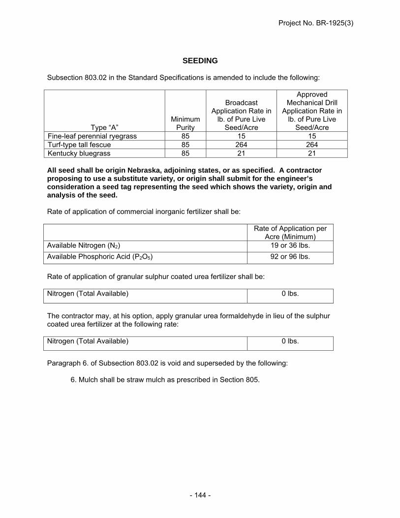
Project No. BR-1925(3)
- 144 -
SEEDING
Subsection 803.02 in the Standard Specifications is amended to include the following:
Type “A” Minimum
Purity
Broadcast
Application Rate in lb. of Pure Live
Seed/Acre
Approved Mechanical Drill
Application Rate in lb. of Pure Live
Seed/Acre Fine-leaf perennial ryegrass 85 15 15 Turf-type tall fescue 85 264 264 Kentucky bluegrass 85 21 21 All seed shall be origin Nebraska, adjoining states, or as specified. A contractor proposing to use a substitute variety, or origin shall submit for the engineer’s consideration a seed tag representing the seed which shows the variety, origin and analysis of the seed. Rate of application of commercial inorganic fertilizer shall be: Rate of Application per
Acre (Minimum) Available Nitrogen (N2) 19 or 36 lbs.
Available Phosphoric Acid (P2O5) 92 or 96 lbs.
Rate of application of granular sulphur coated urea fertilizer shall be: Nitrogen (Total Available) 0 lbs.
The contractor may, at his option, apply granular urea formaldehyde in lieu of the sulphur coated urea fertilizer at the following rate: Nitrogen (Total Available) 0 lbs.
Paragraph 6. of Subsection 803.02 is void and superseded by the following: 6. Mulch shall be straw mulch as prescribed in Section 805.

Project No. BR-1925(3)
- 145 -
EROSION CONTROL Subsection 807.01 in the Standard Specifications is void and superseded by the following: This work shall consist of the preparation of slopes and waterways and the furnishing
and application of soil retention blankets at the locations shown in the plans. Paragraphs 2., 2.a., 2.b. and 2.c. of Subsection 807.02 are void and superseded by the
following: Wire staples shall be used for anchoring the soil retention blanket. The staples shall be
a minimum of 13 gauge U-shaped steel wire with a 1 inch or larger throat with at least 6 inch long legs.
Paragraph 5. of Subsection 807.02 is void. Subsection 807.02 is amended to include the following:
Minimum Purity (%)
Application rate in lb. of Pure Live Seed/1000 yd.²
Perennial ryegrass – Linn 85 1.25 Thickspike wheatgrass – Critana 85 0.75 Slender wheatgrass 85 1 Western wheatgrass – Flintlock, Barton, Arriba 85 1.5 Switchgrass – Blackwell, Pathfinder 90 0.25 Sideoats grama – Trailway, Butte 75 1 Sand lovegrass (Eragrostis trichodes) 85 0.2 Little bluestem – Blaze, Camper, Aldous 60 0.6 Purple prairie clover – Kaneb, inoculated 85 0.05 Oats/Wheat* 90 4 All seeds shall be origin Nebraska, adjoining states, or as specified. A Contractor proposing to use a substitute variety or origin shall submit for the Engineer’s consideration a seed tag representing the seed, which shows the variety, origin and analysis of the seed. Rate of application of inorganic fertilizer shall be:
Rate of Application
Per 1000 yd.² (Min.)
Available Nitrogen (N2) --------------------------------- 4 or 9 lb.
Available Phosphoric Acid (P2O5) -------------------- 23 or 24 lb.

Project No. BR-1925(3)
- 146 -
Rate of application of granular sulphur coated urea fertilizer or urea-formaldehyde fertilizer shall be:
Rate of Application
Per 1000 yd.² (Min.)
Nitrogen (Total Available) ------------------------------ 0 lb.
Paragraph 6.c. of Subsection 807.03 is void. Paragraphs 7.a.i. and 7.a.ii. of Subsection 807.03 are void. Paragraph 8. of Subsection 807.03 is void. Paragraph 1. of Subsection 807.05 is amended to include the following: Pay Item Pay Unit Erosion Control, Class ____ Square Yard (SY)
COVERCROP SEEDING (H-14-0515)
Subsection 812.01 Paragraph 2. is void and superseded by the following: Cover crop seeding shall be applied to any disturbed area requiring erosion
protection. It is intended to be used in staged construction areas, surcharge areas, or other disturbed areas that have not been permanently seeded.
Subsection 812.02 Paragraph 4. is void. Subsection 812.04 is void and superseded by the following: Subsection 812.04 1. Cover crop seeding is measured by the acre of ground surface seeded. The
areas will be calculated from surface measurements of the length and width + 1 yard (+ 900 mm).
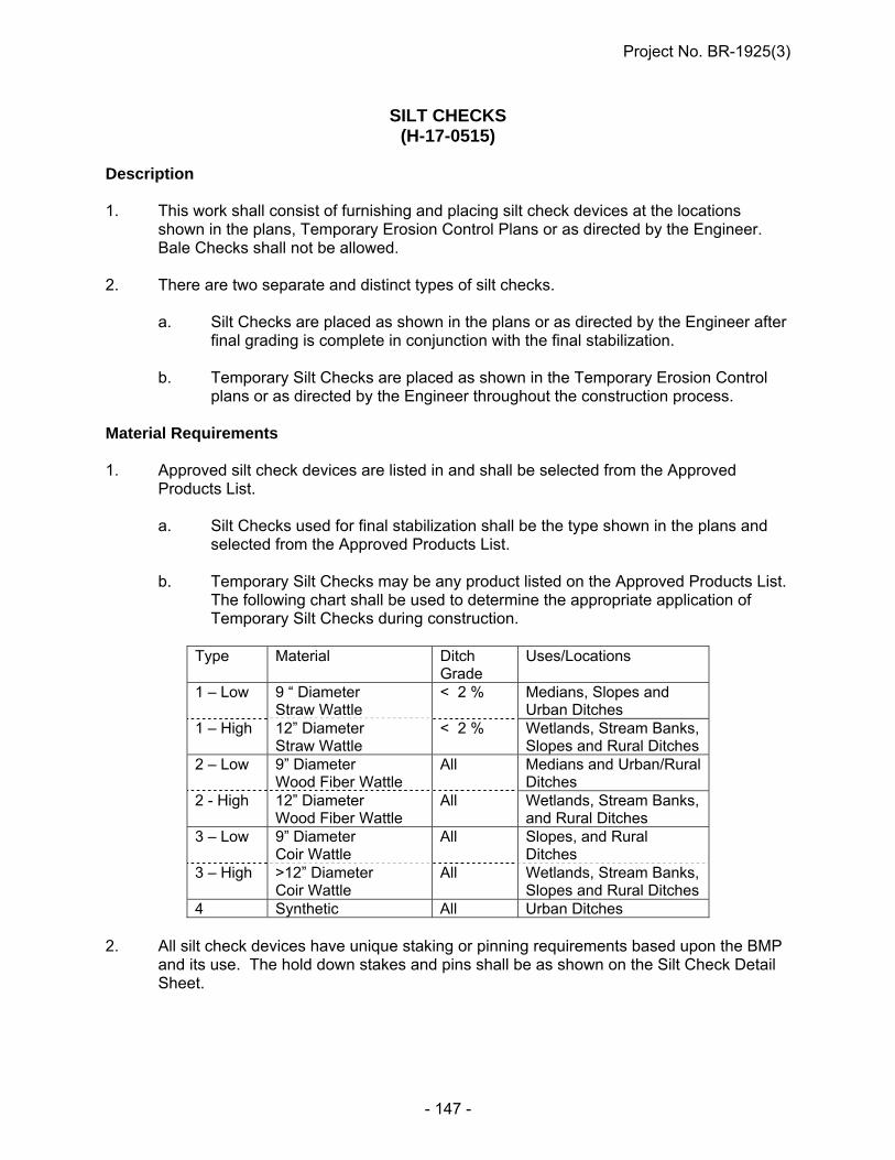
Project No. BR-1925(3)
- 147 -
SILT CHECKS (H-17-0515)
Description 1. This work shall consist of furnishing and placing silt check devices at the locations
shown in the plans, Temporary Erosion Control Plans or as directed by the Engineer. Bale Checks shall not be allowed.
2. There are two separate and distinct types of silt checks. a. Silt Checks are placed as shown in the plans or as directed by the Engineer after
final grading is complete in conjunction with the final stabilization. b. Temporary Silt Checks are placed as shown in the Temporary Erosion Control
plans or as directed by the Engineer throughout the construction process. Material Requirements 1. Approved silt check devices are listed in and shall be selected from the Approved
Products List. a. Silt Checks used for final stabilization shall be the type shown in the plans and
selected from the Approved Products List. b. Temporary Silt Checks may be any product listed on the Approved Products List.
The following chart shall be used to determine the appropriate application of Temporary Silt Checks during construction.
Type Material Ditch
Grade Uses/Locations
1 – Low
9 “ Diameter Straw Wattle
< 2 % Medians, Slopes and Urban Ditches
1 – High
12” Diameter Straw Wattle
< 2 % Wetlands, Stream Banks, Slopes and Rural Ditches
2 – Low 9” Diameter Wood Fiber Wattle
All Medians and Urban/Rural Ditches
2 - High 12” Diameter Wood Fiber Wattle
All Wetlands, Stream Banks, and Rural Ditches
3 – Low
9” Diameter Coir Wattle
All Slopes, and Rural Ditches
3 – High
>12” Diameter Coir Wattle
All Wetlands, Stream Banks, Slopes and Rural Ditches
4 Synthetic All Urban Ditches 2. All silt check devices have unique staking or pinning requirements based upon the BMP
and its use. The hold down stakes and pins shall be as shown on the Silt Check Detail Sheet.

Project No. BR-1925(3)
- 148 -
Construction Methods 1. The silt checks shall be placed as shown in the plans or as directed by the Engineer and
secured in accordance with the plans. 2. The limits of the completed silt check shall extend up the foreslope and backslope of the
ditch to effectively contain the run-off and prevent erosion and washout at the edges of the installation as shown on the Silt Check Detail Sheet.
3. Temporary Silt Checks a. The “Temporary Silt Checks” shall be installed at the locations shown in the
plans, Temporary Erosion Control Plan and as directed by the Engineer. b. The “Temporary Silt Checks” shall be installed immediately after the rough
grading is completed in an area. c. The “Temporary Silt Check” shall be left in place until the finish grading begins.
Reinstall the “Temporary Silt Checks” as soon as finish grading is done unless the permanent erosion control is initiated immediately after finish grading. “Temporary Silt Checks” should be in place at all times after finish grading until permanent “Silt Check,” are in place.
d. The Temporary Silt Check shall be removed and remain the property of the
Contractor when it is no longer functional or needed. Method of Measurement 1. All work involved in constructing silt checks as described above will be included and paid
for per linear feet of devices used in the silt checks. 2. “Temporary Silt Checks” shall be measured by the linear foot (meter) for the initial
installation. The removing or replacing of the temporary silt checks will not be measured for payment, but will be considered subsidiary to the initial installation.
3. Removal of sediment will be measured based on equipment rental. All incidentals
associated with the cleanout shall be subsidiary to the equipment rental items. Basis of Payment 1. Pay Item Pay Unit Silt Check, Type _____ Linear Foot Temporary Silt Check Linear Foot Rental of Skid Loader, Fully Operated Hour Rental of Loader, Fully Operated Hour Rental of Crawler Mounted Hydraulic Excavator, Fully Operated Hour Rental of Dump Truck, Fully Operated Hour 2. Payment is full compensation for all work prescribed in this Section.
Project No. BR-1925(3)
- 149 -
SILT FENCE (H-18-0515)
Section 809 of the Standard Specifications is void and superseded with the following: Description This work shall consist of installing the silt fence at locations shown in the plans and at locations as approved or determined by the Engineer. The installation shall be in accordance with these Specifications, the special provisions, and the plans. Material Requirements 1. All silt fence material shall be selected from the NDR Approved Products List. a. Low Porosity Silt Fence is typically used for perimeter control. b. High Porosity Silt Fence is used for velocity control. c. Low Profile Silt Fence is used for perimeter control and inlet protection. d. Coir Silt Fence is used for perimeter control of wetlands and locations specified
to use a biodegradable silt fence. e. Temporary Silt Fence shall be any product from the silt fence category of the
Approved Products List with a use appropriate to the situation. 2. Silt Fence Posts a. The silt fence posts shall be Studded “T” Steel Posts with a minimum weight of
1.25 lbs/foot (37 Kg/m). b. Used Studded “T” Steel Posts are acceptable. c. Coir Silt Fence shall be installed with wooden posts, derived from hardwood tree
species. The posts shall only be driven until firm. 3. Wire staples shall be used for anchoring the silt fence. 4. Silt Fence shall be attached to the posts with black zip ties. Zip ties shall be UV
stabilized, black with a 50 lb (22 Kg) minimum tensile strength. Construction Methods 1. The silt fence shall be installed and in good working condition prior any grading or
excavation operations and as needed throughout the construction process. The silt fence installation shall not exceed the amount required for the current construction season.

Project No. BR-1925(3)
- 150 -
2. Silt Fence may be installed in the ground by either of the two methods listed below. a. Trenching Method (i) The Contractor shall excavate a trench to the depth, width, and length
shown in the plans.
(ii) The Contractor shall place the silt fence in the trench and pin it as shown in the plans.
(iii) The Contractor shall backfill the trench, compact the soil, and attach the fabric to the posts as shown in the plans.
b. Slicing Method (i) The Contractor shall install silt fence by mechanically slicing the material
into the soil.
(ii) The Contractor shall compact the soil and attach the fabric to the posts as shown in the plans.
3. Fabric Silt Fence installed in a wetland or below water conditions. a. Trenching is not required. Fold a 6 inch (150 mm) flap toward the sediment
source and pin as shown in the plans. Install the stakes as for a dry installation. Attach the fabric to the posts with zip ties or other approved methods and secure from slipping down the post. For a wetland or below water installation, the sediment shall be left in place.
4. All silt fence splice joints shall be overlapped a minimum of 6 feet (1.8 m). 5. The Contractor shall remove sediment that accumulates near the silt fence during
construction and dispose it in an upland location. a. Sediment removal shall be initiated when sediment depth has reached one-half
the height of the above ground portion of the silt fence or as directed by the Engineer in conjunction with silt fence repairs.
b. Sediment shall be removed to approximately 6 inches (150 mm) from the silt
fence. c. Each time sediment is removed, the silt fence shall be repaired to a good working
condition. Good working condition includes fabric repair, retrenching, post repair, tie replacement, and any associated hand work.
6. The Contractor shall maintain the silt fence in good working condition throughout the life
of the construction project. Upon completion of the project silt fence shall remain in place in good working condition, in locations specified in the plans or at locations specified by the Engineer.
a. Silt fence may be removed from locations during construction or upon completion
of the project as directed by the Engineer.

Project No. BR-1925(3)
- 151 -
b. Silt fence that has been determined to be unnecessary and is subject to removal shall be cut off at ground level and shall remain the property of the Contractor for disposal. Any accumulated sediment shall be removed to an upland location.
c. Silt fence posts from removed fence shall remain the property of the Contractor
and may be reused on other installations. d. Temporary Silt Fence shall be removed at the completion of the project or when
it is no longer functional. Method of Measurement 1. Fabric silt fence is measured by the length of the silt fence in linear feet (meter). 2. Removal of sediment from the silt fence will be measured based on equipment rental. 3. All silt fence repairs, such as fabric repair, tie replacement, retrenching, and splicing and
associated handwork are subsidiary to the appropriate silt fence item. 4. Removal of silt fence and all of its components is subsidiary to the silt fence item. Basis of Payment 1. Pay Item Pay Unit
Fabric Silt Fence “Low Porosity” Linear Foot (LF) [Meter (m)] Fabric Silt Fence “High Porosity” Linear Foot (LF) [Meter (m)] Fabric Silt Fence “Low Profile” Linear Foot (LF) [Meter (m)] Fabric Silt Fence “Coir Fiber” Linear Foot (LF) [Meter (m)] Temporary Silt Fence Linear Foot (LF) [Meter (m)] Rental of Skid Loader, Fully Operated Hour (h) Rental of Loader, Fully Operated Hour (h) Rental of Dump Truck, Fully Operated Hour (h) Rental of Crawler Mounted Hydraulic Excavator, Fully Operated Hour (h) 2. Payment is full compensation for all work prescribed in this Section.
GUARDRAIL END TREATMENT, TYPE II (I-2-0414)
Section 902 in the Standard Specifications is amended to include “Guardrail End Treatment, Type II”. This work consists of furnishing and installing a guardrail end treatment system according to the details and at the locations shown in the plans.

Project No. BR-1925(3)
- 152 -
The Contractor has the option of installing one of the following systems:
1.) SRT-31 Manufactured by Trinity Industries, Inc. 2525 N. Stemmons Freeway Dallas, TX 75207 (800) 644-7976
2.) FLEAT-SP-MGS Manufactured by Road Systems, Inc. 3616 Old Howard County Airport Big Springs, TX 79720 (915) 263-2435
3.) X-LITE (Flared) Manufactured by Lindsay Manufacturing 505 Crown Point Ave. Omaha, NE 68110 (402) 210-4593
The lengths of manufacturers’ end treatments vary; the Contractor must install a total length of 53’-1.5”, including the end treatment, to last post with curved end or rectangular “head” beyond the last post. The additional length required will be W-beam guardrail with the Midwest Guardrail System 31” design. The Contractor will be required to furnish two sets of shop plans to the Department of the system to be installed. The guardrail end treatment shall be installed in accordance with the recommendations of the manufacturer. Payment shall be full compensation for all work required to provide and install the system.
TIMBER AND LUMBER (J-5-0711)
Paragraphs 2.a. and 2.b. of Subsection 1075.02 in the Standard Specifications are void and superseded by the following: 2. a. The creosote, pentachlorophenol and copper naphthenate preservative treatment
for timber and lumber shall be by the Empty-cell (Rueping) Process; and, where allowed, the ammoniacal copper arsenate (ACA), chromated copper arsenate (CCA), and ammoniacal copper zinc arsenate (ACZA) preservative treatment for timber and lumber shall be by the Full-cell (Bethel) Process. Treatment shall conform to the requirements as specified in T1-Use Category System: User Specification for Treated Wood of the American Wood-Preservers' Association Standards and AASHTO M 133. Preservatives shall meet the requirements of Section 1076.
b. Preservative Treatment. The preservative treatment and minimum retentions for
timber and lumber shall conform to the requirements as specified in U1-Use Category System: User Specification for Treated Wood of the American Wood Preservers’ Association Standards as amended herein. Minimum retentions for all timber and lumber shall conform to Use Category UC4C. Minimum retentions for fence posts shall conform to Use Category UC4A. Timber and lumber to be
Project No. BR-1925(3)
- 153 -
treated with ammoniacal copper arsenate or ammoniacal copper zinc arsenate shall be dried to the fiber saturation point required to put the timber into satisfactory condition to accept the preservative and attain the required preservative retention and penetration. After treatment, with the exception of offset blocks and posts for guardrail terminals systems, the material shall be redried and have a moisture content of not more than 30 percent at the time or shipment to the job site.
Paragraph 1.b. of Subsection 1075.05 is void and superseded by the following: b. Species. Unless otherwise specified, sawn wood guardrail posts shall be either
Douglas Fir (Coast Region) or Southern Yellow Pine. Wood offset blocks shall be either Douglas Fir (Coast Region), Southern Yellow
Pine (major or minor species), or Ponderosa Pine.
PORTLAND CEMENT CONCRETE (J-15-0216)
Paragraph 1. of Subsection 1002.02 in the Standard Specifications is amended to include the following: Concrete mixes will be in accordance of Table 1002.02. Paragraph 3. of Subsection 1002.02 is void and superseded by the following:
3. Type IP, IS and IT Interground/Blended cement shall be used for all classes of concrete except for pavement repair. Type IP, IS and IT Interground/Blended cement shall meet all requirements of ASTM C 595. Pavement repair shall include Type I/II Portland Cement for Class PR1 Concrete and Type III Portland Cement shall be used in Class PR3 Concrete.
Tables 1002.02 and 1002.03 in Subsection 1002.02 are void and superseded by the following:

Project No. BR-1925(3)
- 154 -
ENGLISH TABLE 1002.02
Class of Concrete
(1)
Base Cement
Type
Total Cementitious
Materials Min. lb/cy
Total Aggregate
Air Content % Min.-Max.
(2)
Coarse Aggregate
(%)
Water/Cement Ratio Max.
(3)
Required Strength Min. psi
Min. lb/cy Max. lb/cy
47B**
IP/IS/IT*
564 2850 3150 6.5 - 9.0 - 0.45 3500
47B*** 564 2850 3150 6.0 - 8.5 - 0.45 3500
47BD 658 2500 3000 6.0 - 8.5 30+3 0.42 4000
47B-HE 752 2500 3000 6.0 - 8.5 30+3 0.40 3500
BX(4) 564 2850 3150 6.0 - 8.5 - 0.45 3500
47B-OL**** 564 2850 3200 5.0 - 7.0 30+3 0.36 4000
PR1 I/II 752 2500 2950 6.0 - 8.5 30+3 0.36 3500
PR3 III 799 2500 2950 6.0 - 8.5 30+3 0.45 3500
SF(5) I/II 589 2850 3200 6.0 - 8.5 50+3 0.36 4000
(1) Each class of concrete shall identify the minimum strength requirement, per plans and specifications. All classes of concrete shall be air-entrained and a water-reducing admixture shall be used per manufacture’s recommendations.
• Class R Combined Aggregate shall use a mid-range water reducer admixture. The dosage shall be at the manufacture’s recommendation and the Engineer may approve a low-range water reducer admixture.
(2) As determined by ASTM C 138 or ASTM C 231. FOR INFORMATION ONLY. The Contractor may develop a Quality Control Program to check the quantity of air content on any given project; such as,
checking the air content behind the paver. (3) The Contractor is responsible to adjust the water/cement ratio so that the concrete supplied achieves the required compressive strength
without exceeding the maximum water/cement ratio. The minimum water/cement ratio for any slip form concrete pavement is 0.38, unless the Contractor requests approval from the Engineer in writing to change the minimum water/cement ratio to 0.36.
(4) For temporary surfacing, Type I/II cement is allowed. (5) Minimum Portland Cement shall be 564 lbs/cyds and the total Silica Fume added shall be 25 lbs/cyds.
(*) Refer to Subsection 1004.02 for material characteristics. Lithium Nitrate may be used in place of Supplemental Cementitious Materials (SCMs), see Section 1007 of the Standard Specifications as modified in these Special Provisions. (**) For slip form applications. (***) For hand-pours and substructures applications. (****) When IP using Class N pozzolan, the maximum water/cement ratio is 0.41.
Project No. BR-1925(3)
- 155 -
Table 1002.03 Table of Acceptable Concrete Class Substitutions Class Specified Acceptable Class for Substitution
BX 47B, 47BD or 47B-HE 47B 47BD or 47B-HE
Paragraphs 5., 6., 7., 8., 9. and 10. of Subsection 1002.02 are void and superseded by the following:
5. Class PR1 and PR3 Concrete:
a. The calcium chloride for use in PR concrete shall be either:
(1) A commercially prepared solution with a concentration of approximately 32 percent by weight.
(2) A Contractor prepared solution made by dissolving 4.5 pounds of
Grade 2 or 6.2 pounds of Grade 1 calcium chloride per gallon of water to provide a solution of approximately 32 percent by weight.
b. The 7.4 pounds of water in each gallon of solution shall be considered part
of the total water per batch of concrete.
c. The calcium chloride solution shall be added, just prior to placement, at a rate of 0.375 gallons/100 pounds of cement (1.4 lb. calcium chloride per
100 lb. cement).
d. Class A, Flaked or Pellet Calcium Chloride shall be added at a rate not to exceed 2.0 percent of the weight of the cement for Grade 1, or 1.6 percent of the weight of the cement for Grade 2. Grade 1 Calcium Chloride purity is between 70 and 90 percent and Grade 2 Calcium Chloride is between 91 and 100 percent.
e. Where mixing trucks are used:
(1) For Class PR3 Concrete, calcium chloride shall be thoroughly mixed
into the concrete before placement. The minimum mixing time is 2 minutes.
(2) For Class PR1 Concrete, calcium chloride shall be added first and
then the concrete mixed at least 2 minutes or as required by manufacturer. Next, the Type F high range water-reducer admixture is added and the concrete is mixed an additional 5 minutes.
6. Class High Early (47B-HE) Concrete
a. High Early (47B-HE) concrete shall be cured as prescribed in
Subsection 603.03, Paragraph 7. The Contractor shall take necessary curing measures so the required strength is achieved.

Project No. BR-1925(3)
- 156 -
b. High Early concrete shall achieve a compressive strength of 3,500 psi at 48 hours after placement.
c. The 48-hour compressive strengths shall be used to determine pay factor
deductions for high early concrete in accordance with Table 603.03.
d. A non-calcium chloride accelerator shall be used when the ambient temperature at the time of the placement of concrete is 70°F or less.
e. When requested by the Contractor, the maturity method, as provided in NDR C 1074, may be used in lieu of the requirements of Subsection 603.03,
Paragraphs 11.c. and d. to determine the strength of concrete pavement for the purpose of early opening to traffic and acceptance. Requests by the Contractor for use of the maturity method shall be on a project basis and shall be made in writing to the Engineer.
7. The yield of the concrete proportions shall be determined and adjusted by the
Producer. 8. All Classes of Concrete with the exception of PR1 and PR3 shall have a Durability
Factor not less than 70 and a mass loss not greater than five percent after 300 freeze/thaw cycles when tested in accordance with ASTM C 666. The freeze/thaw testing shall be conducted according to Procedure A.
Paragraphs 1. & 2. of Subsection 1002.03 are void and superseded by the following: 1. The Contractor shall identify the plant that will supply the concrete 14 days before
use and be entirely responsible for its calibration, batching of concrete, aggregate and sampling of cement per NDR Sampling Guide.
a. The Contractor shall be responsible for the following: 1) Batching concrete. 2) Contractor shall sample aggregate from the conveyor belt or
stockpile. Gradations from a split sample shall be tested in accordance to Section 1033 and reported to the Engineer at the frequency required by the Materials Sampling Guide.
i. Contractor shall retain possession of the split samples on-site at the Contractor’s facility until such a time as determined by the Engineer.
a. At the pre-construction meeting: 1) Contractor shall determine the location of
testing and report the names of the technician performing the sampling and testing.
2) Engineer will notify the Contractor of the retrieval of the split samples.
Project No. BR-1925(3)
- 157 -
ii. The Contractor shall split the sample, place the Department’s split sample into a cloth bag and immediately seal the split sample with the provided security seal. The cloth sample bag shall be supplied by the Department.
iii. The sampling splitting and placement of the security seal of
aggregate samples shall be witnessed by certified Department personnel.
iv. Contractor shall secure the split sample using a consecutively
numbered security seal of 75 pounds breaking strength provided by the Department. The Contractor shall use the consecutively numbered security seals to identify and track each Aggregate Class. Samples that are not consecutively numbered will be investigated for custody of the sample and the Engineer may cease production until it is determined what action will be required.
a. The Contractor shall report the security seal tracking
number with the split sample gradation. b. The following training shall be required for personnel
who oversee the batching of the concrete: 1) Concrete Technician Personnel i. Concrete Plant Technician 2) Portland Cement Sampler i. NDR Portland Cement Sampler 2. Portland Cement Concrete shall be supplied by certified Ready Mix Plants that are
in compliance with the requirements in the Quality Control Manual, Section 3, -- Certification of Ready Mixed Concrete Production Facilities published by the National Ready Mixed Concrete Association. Refer to NDR Material Sampling Guide for the policy on stationary and portable plants.
Paragraph 4. of Subsection 1002.03 is void and superseded by the following: 4. a. Mix times shall meet the requirements of ASTM C 94. Mixing time tests shall
be repeated whenever the concrete appearance indicates that mixing was inadequate.
b. Batch plants that are transporting the concrete in non-agitating trucks, the
mixing time will not be less than 60 seconds, and for agitating trucks, the mixing time will not be less than 45 seconds.
c. The Certification of stationary and portable ready mix plants will conform to
the tests that are required in the NDR Materials Sampling Guide.
Project No. BR-1925(3)
- 158 -
Paragraph 6. of Subsection 1002.03 is void and superseded by the following: 6. Batch tickets shall be prepared as prescribed in the National Ready Mixed Concrete
Association's Quality Control Manual. The Contractor shall keep all gradations and batch tickets until final acceptance by the Department. Projects that have less than 200 cubic yards of concrete placed will be allowed to have hand written tickets. For projects greater than 200 cubic yards, hand written tickets will be at the Engineer’s discretion. The concrete batch tickets shall show batch weights, aggregate moisture (shall be tested daily and moisture probes are allowed), admixtures used, water, and mix design calculations. A copy of the batch ticket shall be given to the Engineer upon delivery of concrete.
Paragraph 8. of Subsection 1002.03 is void and superseded by the following: 8. Coarse aggregate from a dry pit shall be uniformly saturated with water before it is
used. The wetting shall begin 24 hours prior to the concrete mixing to allow complete saturation.
Paragraph 13.a. of Subsection 1002.03 is void and superseded by the following: 13. a. The quantity of water shall be determined by the Contractor. The minimum quantity
of water should be used which will produce required workability. Any additional water used to rinse the charging hopper and fins after the batching of concrete is allowed. This water must be estimated and recorded on the batch ticket.
Subsection 1002.04 is void and superseded by the following: 1. Class 47B Concrete Mix Design Submittal: a. The Contractor shall submit the Concrete Mix Design Worksheet consisting
of design mix proportions, testing of mix design from a minimum of 4 cubic yards and aggregate data for 47B class of concrete being placed on the project.
(1) All testing must be performed by a qualified laboratory found on the
NDR’s Material and Research website, under the Nebraska Qualified Consultant & LPA Laboratories and submitted to the Engineer.
(2) The Concrete Mix Design shall be submitted to the Engineer 4 weeks
prior to any concrete being placed on the project. (3) The Concrete Mix Design shall not be paid for directly by the
Department and shall be subsidiary to items which direct payment is made.
(4) Concrete shall not be placed on the project before the Concrete Mix
Design Worksheet has been reviewed and approved by the Engineer.

Project No. BR-1925(3)
- 159 -
b. The Contractor shall submit the Concrete Mix Design Worksheet to the Engineer. Email submissions are preferred but will be accepted by fax or postal mail.
(1) Contractor’s Mix Design Worksheet can be found on the Materials
and Research website. The submitted Mix Design Worksheet shall include the following:
Contractor Name Project Number Date Location of ready mix or central mix plant Date submitted Signature of Contractor representative
(2) Material Source Information.
Cement Manufacturer Type of Interground/Blended Cement Type of Admixtures Aggregate Pit and Quarry location
(3) Specific Gravity of each individual aggregate source.
(4) Sand Equivalent for dry pit sand-gravel aggregate.
(5) Combined Aggregate percent passing as described on
Table 1033.03C.
(6) Contractor’s Target combined aggregate gradation percent passing. (i) The Contractor’s required worksheet can be found on the
Materials and Research website.
(7) Testing of Mix Design:
The mix design shall show the weights of all ingredients including Interground/Blended cements, aggregates, water, admixtures types and water cement ratio.
Temperature of concrete at time of sampling,
ASTM C 1064.
The air content of plastic concrete, ASTM C 231.
Weight per cubic foot, Yield, ASTM C 138. The relative Yield shall be a minimum of 97%.

Project No. BR-1925(3)
- 160 -
Compressive strength shall be performed with a minimum of three averaged specimens at 7-day and 28-day, ASTM C 39. The minimum 28-day compressive strength shall be 3500 psi.
(8) Traditional 47B Mix Design is defined as a 70 percent Class B
Aggregate and 30 percent Class E Aggregate may be exempt from the concrete testing described in Paragraph 1.(b)(7). All other requirements shall be included in the Concrete Mix Design Report.
c. The PCC Engineer will notify the Contractor of the mix design approval for
Class 47B Concrete. Approval of the mix design does not alleviate the Contractor of the responsibility of the in-place concrete. The Contractor may adjust admixtures, water cement ratio, vibrator frequency, etc., as needed in accordance to the specifications.
d. The Contractor shall submit a new concrete mix design worksheet meeting
the above requirements when a change occurs in the source, type, or proportions of cements or aggregates; unless otherwise approved by the Engineer.
2. The quantity of water to be used shall be determined by the Contractor. It shall not
be varied without the Engineer's consent. 3. If the concrete mixture is excessively wet causing segregation, excessive bleeding,
excessively dry or any other undesirable condition, the concrete shall be rejected. At the option of the Engineer, slump tests may be performed to determine the consistency.
4. Concrete which has developed initial set before it is consolidated and finished shall
be rejected. 5. a. If false set is encountered, the batching operation shall be stopped until the
problem is resolved. b. Each batch must be mixed or agitated for at least 3 additional minutes after
observing the false set and the concrete must be of satisfactory consistency. 6. Compressive strength tests shall be made in accordance with ASTM C 39. 7. Concrete shall be sampled as prescribed in the NDR Materials Sampling Guide.
Samples shall be taken at the point of placement, never before the discharge from the last conveyance.
8. Aggregate Acceptance, Verification, Sampling and Testing: a. The aggregate will be accepted based on the Contractor’s testing results
except as noted below.
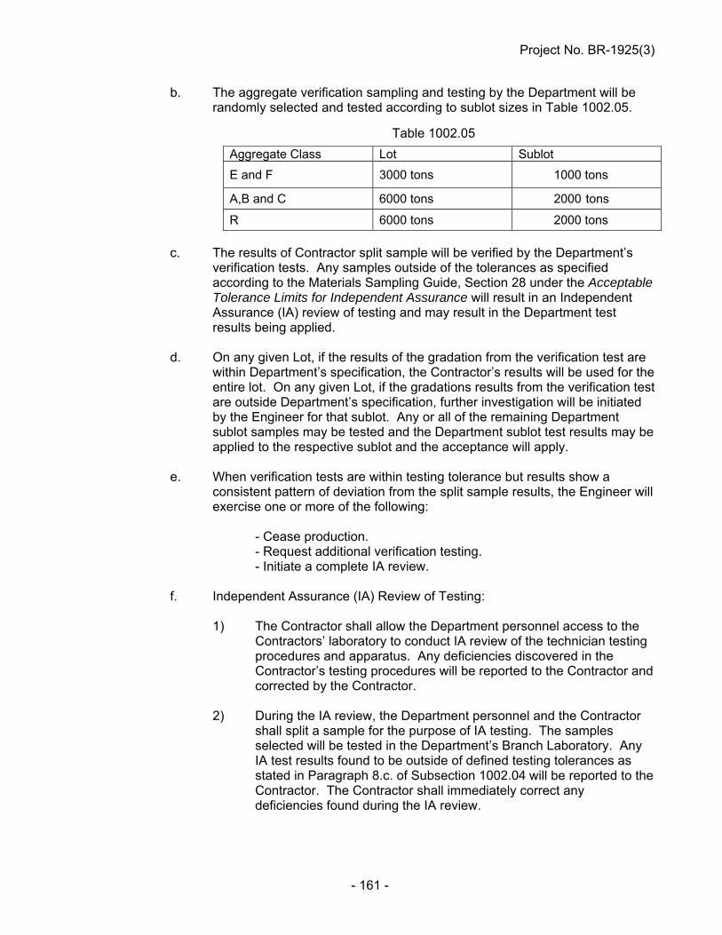
Project No. BR-1925(3)
- 161 -
b. The aggregate verification sampling and testing by the Department will be randomly selected and tested according to sublot sizes in Table 1002.05.
Table 1002.05
c. The results of Contractor split sample will be verified by the Department’s verification tests. Any samples outside of the tolerances as specified according to the Materials Sampling Guide, Section 28 under the Acceptable Tolerance Limits for Independent Assurance will result in an Independent Assurance (IA) review of testing and may result in the Department test results being applied.
d. On any given Lot, if the results of the gradation from the verification test are
within Department’s specification, the Contractor’s results will be used for the entire lot. On any given Lot, if the gradations results from the verification test are outside Department’s specification, further investigation will be initiated by the Engineer for that sublot. Any or all of the remaining Department sublot samples may be tested and the Department sublot test results may be applied to the respective sublot and the acceptance will apply.
e. When verification tests are within testing tolerance but results show a
consistent pattern of deviation from the split sample results, the Engineer will exercise one or more of the following:
- Cease production. - Request additional verification testing. - Initiate a complete IA review.
f. Independent Assurance (IA) Review of Testing: 1) The Contractor shall allow the Department personnel access to the
Contractors’ laboratory to conduct IA review of the technician testing procedures and apparatus. Any deficiencies discovered in the Contractor’s testing procedures will be reported to the Contractor and corrected by the Contractor.
2) During the IA review, the Department personnel and the Contractor
shall split a sample for the purpose of IA testing. The samples selected will be tested in the Department’s Branch Laboratory. Any IA test results found to be outside of defined testing tolerances as stated in Paragraph 8.c. of Subsection 1002.04 will be reported to the Contractor. The Contractor shall immediately correct any deficiencies found during the IA review.
Aggregate Class Lot Sublot
E and F 3000 tons 1000 tons
A,B and C 6000 tons 2000 tons
R 6000 tons 2000 tons
Project No. BR-1925(3)
- 162 -
3) If the project personnel and the Contractor cannot reach agreement on the accuracy of the test results, the Department Central Laboratory will be asked to resolve the dispute, which will be final. All dispute resolutions will be in accordance with the Quality Assurance Program requirements in the NDR’s Materials Sampling Guide.
PORTLAND AND INTERGROUND/BLENDED CEMENT (J-15-0216)
Section 1004 in the Standard Specifications is void and superseded by the following: 1004.01 – Description 1. Portland cement is the binder in concrete, locking the aggregate into a solid structure. It is
manufactured from Lime, Silica, and Alumina (with a small amount of plaster of Gypsum). 2. Equivalent alkali referred to herein is hereby defined as the sum of the Sodium Oxide
(Na20) and the Potassium Oxide (K20) calculated as Equivalent Alkali Na20e = Na20+ 0.658 K20.
3. Interground and Blended cements consist of intimate and uniform intergrinding or blending
of Portland cement clinker, Slag cement, Pozzolan and/or Limestone. 1004.02 – Material Characteristics 1. Type I, Type II, Type I/II and Type III Portland cement shall conform to the requirements in
ASTM C 150 with the following additional requirements:
a. Portland cement shall not contain more than 0.60 percent equivalent alkali. 2. Interground and Blended Cement shall conform to the requirements in ASTM C 595 with
the following additional requirements: a. Interground/Blended cement (Type IP) (1) For Type IP(25) shall be composed of Class F fly ash or Class N pozzolan
replacement shall be 25% + 2%. (2) For Type IP(20) shall be composed of Class F fly ash or Class N pozzolan
replacement shall be 20% + 2%. b. Interground/Blended cement (Type IS)
(1) For Slag Cement, the maximum replacement shall be 35% +5 when incorporated into the final Interground/Blended cement.
Project No. BR-1925(3)
- 163 -
c. Interground/Blended cement (Type IT)
(1) For SCMs, Slag cement and Limestone, the maximum replacement by weight shall be 40%. The manufacturer has a production tolerance of + 2% from the proposed replacement.
(2) For Limestone cement, the replacement range shall be from 5.1% to 10.0%
when incorporated into the final Interground/Blended cement.
d. No additional SCMs, Slag cement and Limestone will be added at the batch plant. 1004.03 – Procedures 1. The Contractor shall provide adequate protection for the Portland and Interground/Blended
cement against dampness. a. Portland and Interground/Blended cement shall be hauled or stored in railroad cars,
dry bulk trailers or in suitable moisture-proof buildings. b. The use of tarpaulins for the protection of the Portland and Interground/Blended
cement against moisture will not be allowed. 2. No Portland and Interground/Blended cement which has become caked or lumpy shall be
used. 3. Portland and Interground/Blended cement which has been spilled shall not be used. 4. Accepted Portland and Interground/Blended cement which has been held in storage at the
concrete mix plant more than 90 days shall be retested. 5. Portland and Interground/Blended cement coming directly from the manufacturer shall not
be used until the temperature is 150°F or less. 6. Portland cement having false set when tested in accordance with in ASTM C 150 will not be
used. 1004.04 – Acceptance Requirements 1. For Department projects, Portland and Interground/Blended cements must be on the NDR
Approved Product List (APL). 2. The Contractor shall submit any new Portland and Interground/Blended cements to the
Engineer to be approved for the APL with the following: a. Material source information: 1) Mill Location 2) Type of Portland and Interground/Blended cements 3) Grinding Period

Project No. BR-1925(3)
- 164 -
4) Associated Manufacture Product Name 5) Provide source and type of each SCMs and/or Slag Cement used for final
product. (i) The Department will allow the use of ASTM C 1697. a. When two or more SCMs and/or Slag Cement are pre-
blended, the Contractor shall report chemical composition analysis of the final blend.
b. The final blend shall be reported as per ASTM C 1697,
Paragraph 4. 6) Portland cement shall conform to ASTM C 150. 7) Interground/blended cements shall conform to ASTM C 595. 8) Provide total cementitious materials replacement per ASTM C 595. 9) Report test results per ASTM C 1567 at 28-days. 3. Alkali Silica Reaction Requirements and Testing: a. Interground/Blended cement shall be tested according to the provisions of ASTM C 1567. (1) The mortar bars shall be composed of Type IP, IS or IT Interground/blended
cement and sand and gravel from an approved Platte River Valley-Saunders County source.
i. When Elkhorn River-Madison County source or an out of state
aggregate source is being used on a project, the Elkhorn River or an out of state aggregate source shall be used in lieu of the Platte River Valley-Saunders County source.
ii. When Contractor proposes a change of aggregate source, then the
new aggregate source shall be tested by ASTM C 1567. (2) The mortar bars for the ASTM C 1567 shall not exceed 0.10% expansion at
28 days. 4. Portland and Interground/Blended cements will be placed on NDR’s APL based on the
conformance with the NDR’s Acceptance Policy Portland and Interground/Blended Cements.
Project No. BR-1925(3)
- 165 -
1004.05 - Sampling and Testing Requirements 1. All Portland and Interground/Blended cements shall be sampled and tested at the rate as
described in the NDR’s Materials Sampling Guide. a. The Department will inform the Contractor when a sample is required. b. A sample shall be taken by a Contractor’s Certified Portland Cement Sampler and
must be under the supervision of Department certified personnel. c. The sample shall be taken at the plant from a bulk shipment of a rail car, dry bulk
trailer, batch plant silo or from the line between the bulk truck and the silo. Upon sampling, the Department will take immediate custody of the sample.
2. Noncompliant material shall be tested in accordance with ASTM C 1567 and in accordance
with Section 1004.04, Paragraph 3.a. (1). i. The mortar bars for the ASTM C 1567 shall not exceed 0.10% expansion at
28 days. ii. If the expansion is greater than 0.10% at 28 days, then the Interground/Blended
cement shall be subject to removal, 40% pay and/or removal from NDR’s APL in accordance with NDR’s Acceptance Policy on Portland and Interground/Blended Cements.
3. Noncompliant material from the mill, terminal or project will be temporarily removed from
the Approved Products List pending further investigation. 4. If the noncompliant Portland or Interground/Blended cement is removed from the Approval
Products List, all shipments from the supplier will be held until the investigation of the failing samples have been completed by the NDR Materials and Research Division.
WATER FOR CONCRETE (J-15-0214)
Section 1005 in the Standard Specifications is void and superseded by the following: 1005.01 – Description 1. Water shall be free from objectionable quantities of oil, acid, alkali, salt, organic matter, or
other deleterious materials and shall not be used until the source of supply has been approved.
2. Wash water from the mixer washout may be used only with the Engineer’s approval. Use
of wash water will be discontinued if undesirable reaction with admixtures or aggregates occurs.
Project No. BR-1925(3)
- 166 -
1005.02 – Material Characteristics 1. Water which contains more than 0.25 percent total solids by weight shall not be used. 2. When required by the Engineer, the quality of mixing water shall be determined by NDR C
114, NDR T 290, NDR D 512, NDR C 1602, ASTM C 31, ASTM C 109, ASTM C 191, and ASTM C 1603.
3. Upon written request by the concrete producer and approval by Materials and Research,
the concrete producer may utilize up to 10% wash water for batching all classes of concrete with the following conditions:
a. Wash water shall conform to the requirements in NDR’s Material Sampling Guide
under Policy for Certification of Ready Mix Plants. b. Wash water must be clarified wash water that has been passed through a settling
pond system. c. Wash water must be scalped off of a settling basin that has been undisturbed for a
minimum of 12 hours. d. Wash water must be metered into each load. e. Wash water quantities shall be shown on the batch ticket.
CALCIUM CHLORIDE (J-15-0214)
Section 1006 of the Standard Specifications is void and superseded by the following: 1006.01 – Description Calcium Chloride shall be Type S (Solid) or Type L (Liquid). Calcium Chloride can be used for; but not limited to, dust control and acceleration of the set of concrete. 1006.02 – Material Characteristics The requirements for calcium chloride shall be tested in accordance with ASTM D 98. 1006.03 – Acceptance Requirements Acceptance shall be based on requirements contained in the NDR Materials Sampling Guide.
Project No. BR-1925(3)
- 167 -
SECTION 1007 -- CHEMICAL ADMIXTURES (J-15-0214)
Section 1007 in the Standard Specifications is void and superseded by the following: 1007.01 -- Description 1. Admixtures are materials added to Portland cement concrete to change characteristics
such as workability, strength, permeability, freezing point, and curing. 2. The Department's concrete admixture types are: a. Type A - Water-Reducing Admixture - An admixture that reduces the quantity of
mixing water required to produce concrete of a given slump. b. Type B - Retarding Admixture - An admixture that slows the setting of concrete. c. Type C - Accelerating Admixture - An admixture that speeds the setting and early
strength development of concrete. d. Type D - Water-Reducing and Retarding Admixture - An admixture that reduces the
quantity of mixing water required to produce concrete of a given slump and slows the setting of concrete.
e. Type E - Water-Reducing and Accelerating Admixture - An admixture that reduces
the quantity of mixing water required to produce concrete of a given slump and speeds the setting and early strength development of concrete.
f. Type F - Water-Reducing, High Range Admixture - An admixture that reduces the
quantity of mixing water required to produce concrete of a given slump by 12 percent or greater.
g. Type G - Water-Reducing, High Range and Retarding Admixture - An admixture that
reduces the quantity of mixing water required to produce concrete of a given slump by 12 percent or greater and slows the setting of concrete.
h. Air-Entraining - An admixture that encapsulates air in the concrete. i. Lithium Nitrate – An admixture used to control the Akali Silica Reaction (ASR) in
concrete. 1007.02 -- Material Characteristics 1. Type A through G admixtures shall meet the requirements in ASTM C 494. 2. Air-entraining admixtures shall meet the requirements in ASTM C 260. 3. Use of admixtures other than those cited may be requested by the Contractor. 4. Admixtures shall not contain more than 1 percent of chlorides calculated as calcium
chloride unless specified otherwise in the Specification.

Project No. BR-1925(3)
- 168 -
5. Admixtures shall be used at the manufacturer's recommended dosage rates. 6. The air-entraining admixture characteristics shall produce concrete with satisfactory
workability and total air content as prescribed in Table 1002.02. 7. a. When using the Lithium Nitrate admixture, the Contractor shall submit to the
Engineer: (i) A five pound sample of Portland cement that will be used on the project. (ii) The Manufacturer’s method for determining the recommendation for the
required dose rate based on the equivalent alkali content. (iii) Water content of the Lithium Nitrate admixture solution. b. The Engineer will report the equivalent alkali content to the Contractor. The
Contractor shall use the reported equivalent alkali content to determine the required dose rate based on the manufacturer’s recommendation.
1007.03 -- Procedures 1. The process for adding admixtures to a ready mix truck on the project site involves
positioning the load of concrete up to the truck chute, stopping short of discharge. a. The admixture is then poured over the surface of the concrete and mixed for at least
5 minutes. b. No more than 1.3 gallons of water shall be used to rinse the admixture from the fins
and top chute. This water must be shown on the proportioning report and shall not exceed the water cement ratio.
c. When Lithium Nitrate is used, the portion of the admixture that is water will be
shown on the proportioning report and shall not exceed the water cement ratio. d. The Contractor is responsible for the addition of the admixture. 2. a. If the air content is less than the minimum specified, addition of air-entraining
admixtures is allowed. b. The Contractor shall take measures based on manufacturer’s recommendations that
are within compliance of NDR Specifications, to bring the load of concrete into NDR prescribed limits according to Table 1002.02.
c. If the air content is then outside the limits in Table 1002.02, the load of concrete
shall be rejected.
Project No. BR-1925(3)
- 169 -
1007.04 -- Acceptance Requirements 1. a. Approved chemical admixtures are shown on the NDR Approved Products List. b. Admixture approval shall be based upon annual certifications and certified test
results submitted to the NDR Materials and Research Division. 2. The admixture must be essentially identical in concentration, composition, and performance
to the admixture tested for certification. 3. Admixtures not identified on the NDR Approved Products List may be used under the
following conditions: a. A certificate of compliance and certified test results must be submitted to the NDR
Materials and Research Division and approval for use must be given by the NDR Materials and Research Division.
SILICA FUME (J-15-0307)
Paragraph 2 of Subsection 1009.03 in the Standard Specifications is void and superseded by the following:
2. Silica fume shall be protected from temperatures in excess of 90°F (32°C).
LIQUID MEMBRANE-FORMING COMPOUNDS FOR CURING CONCRETE (J-15-0307)
Subsection 1012.03 in the Standard Specifications is void and superseded by the following: 1012.03 – Acceptance Requirements 1. All curing compounds to be approved must be from the current calendar year with no carry-
over from the previous years. 2. Approved compounds are on the NDR Approved Products List. 3. Products not on the NDR Approved Products List shall be sampled and tested in
accordance with requirements of the NDR Materials Sampling Guide.

Project No. BR-1925(3)
- 170 -
BITUMINOUS LIQUID COMPOUNDS FOR CURING CONCRETE (J-15-0515)
Section 1013 in the Standard Specifications is void and superseded by the following: 1013.01 – Description The compound shall consist essentially of an asphaltic base and shall be of a consistency suitable for spraying at temperatures existing at the time of construction operations. It shall form a continuous, uniform film. It shall be free of precipitated matter caused by conditions of storage or temperature. The compounds shall be relatively nontoxic. 1013.02 – Material Characteristics
a. When tested in accordance with AASHTO T 155, the loss of water shall not be more than 0.11 lb/ft2 (0.55 kg/m2) of surface area at 3 days, unless otherwise specified by the Engineer.
b. The Contractor has the option of using bituminous tack coat. The tack coat shall
conform to all requirements of Section 504.
c. The base material shall conform to Sections 1030, 1031 and 1032. 1013.03 – Acceptance Requirements Products shall be sampled and tested in accordance with requirements of the NDR Materials Sampling Guide.
JOINT AND CRACK SEALING FILLER (J-15-0813)
Section 1014 in the Standard Specifications is void and superseded by the following: 1014.01 – Description Joint sealing filler shall be either a cold applied silicone product or an asphalt product (hot pour) conforming to the requirements of this Section. The type of joint filler to be used shall be as specified in the plans or special provisions. If not specified, any of the joint sealing fillers in this Section may be used. Crack sealing filler shall be a hot pour sealer conforming to the requirements of this Section.

Project No. BR-1925(3)
- 171 -
1014.02 -- Material Characteristics 1. NE-3405 and NE-3405LM (hot pour) a. NE-3405 joint and crack sealer shall conform to the requirements of ASTM D6690,
Type II. The material shall conform to the requirements of Table 1 with the following exception:
(i) The test of Bond, non-immersed, ASTM D5329, 3 specimens through
3 cycles shall be run at 0F (-18oC), 100% extension. b. NE-3405LM (Low Modulus) joint and crack sealer shall conform to the requirements
of ASTM D6690, Type IV. The material shall conform to the requirements of Table 1.
c. The test of Bond, non-immersed, ASTM-D5329, will be tested on concrete blocks
that will be constructed by the NDR Concrete Laboratory. The concrete blocks will be made of a 47B concrete mixture as prescribed in Section 1002 in the NDR Standard Specifications. The design is amended so that no fly ash is used in the mixture. All other specifications for Portland Cement Concrete apply.
d. Sample conditioning, preparation and heating shall be in accordance with ASTM D
5167 with the following exceptions: (i) The following sentence of Section 8.1.2, “Also, if present, remove container
liner by cutting it away”, is void and superseded by the following: “Also, if present, as much of the polyethylene bag as possible, shall
be removed by cutting it away. Wholly-meltable type container in contact with the sample section shall be left in place.”
(ii) The last sentence of Section 8.1.2 “Solid Materials” is void and superseded
by the following: The entire vertical section which has been cut, shall be placed into
the pot for melting. (iii) The Section of 8.2.2.1 “Solid Materials” is void. (iv) The Section of 8.2.3 is void and superseded by the following: After the solid segment is added to the melter, the material shall be
allowed to minimally melt to a uniform viscous state suitable for the installation of the stirrer or paddle. The sample shall then be stirred for one full hour. The oil bath temperature shall be regulated to bring the material to the maximum heating temperature within the one hour of stirring.

Project No. BR-1925(3)
- 172 -
(v) The Section of 8.2.4.1 is void and superseded by the following:
During the one full hour of stirring, check the temperature of the material at maximum 15 minute intervals using a Type K thermocouple with the calibration verified in accordance with Section 6.1.7 to ensure conformance with specified temperature requirements. Stop the mechanical stirrer when measuring temperatures. If material temperatures ever exceed the maximum heating temperature, or ever drop below the minimum application temperature after the maximum heating temperature was reached, discard the sample and re-do the heating. Maintain appropriate records of times and temperatures to verify conformance with specification requirements.
(vi) The Section of 8.2.4.2 is void. e. ASTM D 5329 shall include the following changes: (i) Sections 6.4 and 12.4 “Specimen Preparation” shall have the reference of
“177 ml (6 oz.)” replaced with “3 oz.” (ii) Section 6 “Cone Penetration, Non-Immersed” shall be superseded with the
following exceptions: 1. Section 6.5 “Procedure” is void and superseded by the following:
Place the specimen in a water bath maintained at 77 +/- 0.2°F (25 +/- 0.1C) for two hours immediately before testing. Remove the specimen from the bath and dry the surface by shaking gently to remove free water from the surface of the specimen. Using the apparatus described in Section 6.3, make one determination at or near the center of the specimen. Take care to ensure the cone point is placed on a point in the specimen that is representative of the material itself, and is free of dust, water, bubbles, or other foreign material.
2. Section 6.6 “Report” is void and superseded by the following: Record the value as penetration of the specimen in dmm
units. (iii) Section 12 “Resilience” shall be superseded with the following exceptions: 1. Section 12.5 “Procedure”, void the sentence “Make determinations at
three points equally spaced from each other and less than 13mm (½ inch) from the container rim” and supersede with the sentence “Make one determination at or near the center of the tin.”
2. Section 12.6 “Report” is void.

Project No. BR-1925(3)
- 173 -
2. Silicone Joint Sealer (cold applied) a. Silicone joint sealers may be either self-leveling or non-sag and shall meet the
requirements in Table 1014.01.
Table 1014.01 Silicone Joint Sealer Requirement
Property Requirement Test As supplied: Specific Gravity Work Time, minimum Tack-Free, at 25°C Cure Time, at 25°C, maximum Full Adhesion, maximum
1.010-1.515 10 minutes 20-360 minutes 14 days 21 days
ASTM D792
As cured, at 25°C + 1.5 Elongation, minimum Durometer Non-Sag, Shore A Self-Leveling, Shore 00, minimum Joint Movement Capacity Tensile Stress, at 150% Elongation
800% 10-25 40 +100% to -50% 45 psi
ASTM D412 ASTM D2240 ASTM D2240 ASTM C719 ASTM D412
1014.03 -- Packaging 1. NE-3405 and NE-3405LM a. The joint and crack sealer can be packaged in either cardboard box of wholly-
meltable type containers. (i) Cardboard box containers shall be manufactured from double wall kraft
board producing a minimum bursting test certification of 350 PSI (241 N/cm2) and using water-resistant adhesives. The use of metal staples or fasteners of any kind will be prohibited for closing the lids of the boxes. Tape or other like material is acceptable.
a. The joint and crack sealer shall be in meltable [300°F (149C)]
polyethylene bag(s). (ii) Wholly-meltable type containers, and any of their components, shall be fully
meltable and integrational with the joint and crack sealer by the time the manufacturer’s minimum application temperature is reached.
a. The wholly-melted and integrated container must not adversely affect
the test specifications of the joint and crack sealer. 2. Silicone Joint Sealer
a. Each container shall include information regarding manufacturer and product name.

Project No. BR-1925(3)
- 174 -
1014.04 -- Acceptance Requirements
1. NE-3405 and NE-3405LM a. Acceptance of the manufactured material is based on pre-approval by either on or
off-site sampling. Acceptable hot pour sealant lots are listed on the NDR Approved Products List.
(i) NDR on-site field sampling shall be in accordance with the NDR Materials
Sampling Guide. (ii) Off-site (Proxy) sampling shall be in accordance with ASTM D 6690. 1. Proxy sampling shall be overseen by an outside party approved by
the NDR, preferably another DOT Agency. Proxy samples shall include a manufacturer’s Certificate of Compliance. Proxy samples shall also include a dated signature of origin by the Representative that is not affiliated with the manufacturer, and can either be on the Certificate of Compliance, or separate letter.
2. For convenience in both sampling and shipping samples, sample
containers smaller than a manufacturer’s usual production containers are allowed, as long as the sample is 1500 grams min.
3. Samples shall be sent to the NDR Bituminous Laboratory, or
alternatively, sent to an NDR-approved independent laboratory for testing which will be at no cost to the Department. If a NDR-approved independent laboratory will be used for testing purposes, the NDR Bituminous Laboratory must be notified so that NDR concrete blocks for Bond testing can be sent to it.
2. Silicone Joint Sealer
a. Acceptance of applied silicone joint sealers shall be in accordance with the NDR Materials Sampling Guide.
b. Acceptable silicone joint sealer manufacturer products are listed on the NDR
Approved Products List. (i) For products that are not listed, approval may be based upon test results
from an independent laboratory submitted to the NDR Concrete Materials Section by the manufacturer, and testing by the NDR. Approval must be made prior to product use.
Project No. BR-1925(3)
- 175 -
EPOXY COMPOUNDS AND ADHESIVES (J-15-0308)
Section 1018 in the Standard Specifications is void and superseded by the following: 1018.01 – Description This specification provides requirements for two-component, epoxy-resin bonding systems for use in non-load bearing applications and resin adhesives for application to Portland cement concrete. 1018.02 – Material Characteristics 1. Epoxy-resin bonding systems shall conform to the requirements of ASTM C 881. Approved
systems are shown on the NDR Approved Products List. 2. The classification of Epoxy-Resin Bonding Systems is as follows: a. Type I For use in non-load bearing applications for bonding hardened
concrete and other material to hardened concrete. Type II For use in non-load bearing applications for bonding freshly mixed
concrete to hardened concrete. Type III For use in bonding skid resistant materials to hardened concrete, and
as a binder in epoxy mortars or epoxy concretes. b. Grade 1 Low viscosity. Grade 2 Medium viscosity. Grade 3 Non-sagging consistency. c. Class A For use below 40°F (4°C); the lowest allowable temperature to be
defined by the manufacturer of the product. Class B For use between 40°F and 60°F (4°C and 15°C). Class C For use above 60°F (15°C); the highest allowable temperature to be
defined by the manufacturer of the product. Class D For use between 40°F and 65°F (4°C and 18° C). Class E For use between 60°F and 80°F (15°C and 26°C). Class F For use between 75°F and 90°F (24°C and 32°C).

Project No. BR-1925(3)
- 176 -
1018.03 – Procedures 1. The compounds shall be of the type and grade specified in the plans or as directed by the
Engineer. 2. The class of the compounds shall be selected for use according to climatic conditions at the
time of application. 3. All bonding surfaces shall be clean and free of all oil, dirt, grease, or any other materials
which would prevent bonding. 4. Mixing and application shall be in strict accordance with the manufacturer’s instructions. 1018.04 – Acceptance Requirements 1. Epoxy-resin bonding systems and resin adhesives approved for use are shown on the NDR
Approved Products List. 2. Epoxy-resin bonding systems that are not on the NDR Approved Products List may be
accepted based on a manufacturer’s certificate of compliance.
DEFORMED METAL CENTER JOINT AND METAL KEYWAY (J-15-0307)
Paragraph 1 a. of Subsection 1027.01 in the Standard Specifications is void and superseded by the following:
a. Metal Center Joint:
Metal center joint sections shall be manufactured from sheets no less than 18 gauge [0.05 inch (1.3 mm)] thick and shall be of the size and trapezoidal shape shown in the plans. The sections shall be punched along the centerline of the narrow face of the trapezoid to admit the tie bars required by the plans and also at intervals of not greater than 2 feet (600 mm) to receive pins that are driven vertically into the subgrade to support the metal center joint.
AGGREGATES (J-15-0616)
Subsection 1033.01 is amended to include the following paragraphs and Subsection 1033.02, Paragraphs 1., 2. and 3. of the Standard Specifications are void and superseded by the following: 1033.01 – Description This combined aggregate gradation using Class R aggregate is to optimize aggregate blends utilizing more locally available materials.

Project No. BR-1925(3)
- 177 -
Achieving a uniform gradation for Class R may require the use of two or more different aggregates. It is the responsibility of the contractor to consider additional material characteristics; such as, but not limited to particle shape, cubicity, angularity, etc., when designing a mix. 1033.02 -- Material Characteristics 1. Sampling and Testing Procedures:
All materials shall be sampled and tested in accordance with Table 1033.01. All material source locations and quarries must be approved by the Department for prior to use.
Table 1033.01
Sampling and Testing Procedures Procedure Method Sampling NDR T 2 Sieve Analysis NDR T 27 Clay Lumps, Shale, and Soft Particles NDR T 504 Abrasion AASHTO T 96 Freeze and Thaw Soundness NDR T 103 Specific Gravity and Absorption (course aggregate)
AASHTO T 85
Specific Gravity and Absorption (fine aggregate)
AASHTO T 84
Total Evaporable Moisture Content of Aggregates by Drying Plastic Fines in Graded Aggregates and Soils by Use of the Sand Equivalent Test
AASTHO T 255 AASTHO T 176
Sodium Sulfate Soundness AASHTO T 104 Calcium Carbonate NDR C 25 Organic Impurities AASHTO T 21 Mortar-Making Properties AASHTO T 71 Reducing Field Samples of Aggregate to Testing Size
AASHTO T 248
Lightweight Pieces in Aggregates NDR T 113 2. General Aggregate Properties: a. Aggregates shall be free from injurious quantities of dust, soft or flaky particles,
loams, alkali, organic matter, paper, wood or other deleterious matter as determined by the Engineer.
b. Dolomite as herein defined is a magnesium limestone containing calcium carbonate
and magnesium carbonate in approximately a 4 to 3 ratio. c. The calcium carbonate content of limestone shall be at least 80 percent (computed
as CaCO3 from the value determined for CaO). d. Fine Sand shall have at least 95 percent of its particles pass the No. 10 (2.0 mm)
sieve and no more than 25 percent pass the No. 200 (75 µm) sieve. This definition applies to sodium sulfate soundness test.
Project No. BR-1925(3)
- 178 -
e. Once an aggregate’s soundness and abrasion quality has been determined, additional quality testing for soundness and abrasion loss will be at the Engineer’s discretion.
f. All aggregates or combine aggregates that have been washed or coming from a wet
pit shall be stockpiled for a minimum of 48 hours before being introduced into concrete.
3. Portland Cement Concrete Aggregates:
a. Fine Aggregate:
(1) Aggregate shall be washed and composed of clean, hard, durable and uncoated particles.
(2) Aggregates produced from wet pits by pumping must be adequately washed
by means approved by the Department. (3) Aggregates from dry pits shall be adequately washed by means approved by
the Department and have a Sand Equivalent value not less than 90 in accordance with AASTHO T 176.
(i) If the Sand Equivalent is less than 90, the Engineer may elect to stop aggregate production until such a time ASTM C 109 has been completed. The aggregate, when subjected to the test for mortar-making properties, shall produce a mortar having a compressive strength at the age of 7 days equal to or greater than that developed by mortar of the same proportions and consistency made of the same cement and aggregate after the aggregate has been washed to a sand equivalent greater than 90. Materials failing to produce equal or greater strength shall be unacceptable.
(4) Aggregate for concrete shall have a soundness loss of not more than 10%
by weight at the end of 5 cycles using Sodium Sulfate Soundness test AASHTO T 104.
(5) The weight of the aggregate shall not contain more than 0.5% clay lumps.
(6) Aggregate subjected to the colorimetric test for organic impurities which produces a color darker than the standard shall be further tested for its mortar-making properties in accordance with AASHTO T 71. The Engineer may elect to stop aggregate production until such a time AASHTO T 71 testing has been completed.
(i) Aggregate, when subjected to the test for mortar-making properties, shall produce a mortar having a compressive strength at the age of 7 days equal to or greater than that developed by mortar of the same proportions and consistency made of the same cement and aggregate after the aggregate has been treated in a 3% solution of sodium hydroxide. Materials failing to produce equal or greater strength shall be unacceptable, except when determined to be acceptable under the provisions of Subsection 105.03.

Project No. BR-1925(3)
- 179 -
(7) Aggregate shall meet the requirement in Tables 1033.02A, 1033.02B and 1033.03C.
(8) Lightweight pieces (measured by percent by volume values) shall not
exceed 3.5%. For Class R aggregate, fine aggregate is defined as any material passing a No. 4 sieve.
Table 1033.02A
Percentage
Percent Passing 1½” 1” ¾” ½” 3/8 No.4 No.10 No.20 No.30 No.200
AGGREGATE SPECIFICATION RANGE
Class A Max Min
-- -- -- -- 100 100 92
90 64
-- 40 10
3 0
Class B Max Min
-- 100 -- -- -- 97 77
70 50
-- 40 16
3 0
Class C Max Min -- 100 -- -- --
88 44
50 24
-- 20 4
3 0
Table 1033.02B Aggregate Classes and Uses
Aggregate Class Concrete Description A Overlay Concrete SF B 47BD, 47B-HE, 47B-OL, PR 1 and PR 3 C BX
b. Coarse Aggregate: (1) Aggregate shall consist of Limestone, Quartzite, Dolomite, Gravel and
Granite composed of clean, hard, durable, and uncoated particles. (2) The percent of clay lumps, shale, soft particles or lightweight pieces shall not
exceed the following amounts:
Clay Lumps .......................... 0.5% Shale ................................... 1.0% Soft Particles ....................... 3.5% Lightweight Pieces .............. 3.5%
(3) Any combination of clay lumps, shale and soft particles (all percent by weight
values), plus the lightweight pieces (a percent by volume value) shall not exceed 3.5%. For Class R aggregate, coarse aggregate is defined as any materials retained on a No. 4 sieve.
(4) Aggregate for concrete shall be free of coatings that will inhibit bond and free
of injurious quantities of loam, alkali, organic matter, thin or laminated pieces, chert, or other deleterious substances as determined by the Engineer.
(5) Aggregate for concrete shall not have a soundness loss greater than 8.0%
by weight at the completion of 16 cycles of alternate freezing and thawing. (6) Aggregates for concrete shall have a Los Angeles Abrasion loss percentage
of not more than 40.
Project No. BR-1925(3)
- 180 -
(7) All fractions passing the No.4 sieve shall meet quality requirement of soundness loss of not more than 10% by weight at the end of 5 cycles using sodium sulfate solution.
(8) The coarse aggregate shall be tested according to ASTM C 1260. (a) The mortar bars for the ASTM C 1260 shall not exceed 0.10%
expansion at 28 days.
(i) If the proposed coarse aggregate exceeds 0.10% expansion at 28 days, the aggregate proportions used on the project shall be tested in accordance to ASTM C 1567.
a. The ASTM C 1567 mortar bars shall be composed of Interground/blended cement being used on the project.
b. If the expansion is greater than 0.10%, the coarse aggregate shall not be used.
(9) Aggregate shall meet the requirements in Tables 1033.03A, B, and C.
Table 1033.03A
Percent Percent Passing
1 ½” 1” ¾” ½” 3/8 No.4 No.10 No.20 No.30 No.200
AGGREGATE SPECIFICATION RANGE
Class E Max Min
100 100 92
90 66
-- 45 15
12 0
-- *4 0
-- 3 0
Class F Max Min
-- -- 100 100 96
90 40
30 4
8 0
-- -- 3 0
*If the No. 200 sieve is less than 1.5% passing the No.20 sieve could be increased to maximum of 6% passing.
Table 1033.03B
Aggregate Classes and Uses Aggregate Class
Concrete Description
E 47BD, 47B-HE, PR 1 and PR 3
F 47B-OL, Overlay Concrete SF c. Combined Aggregates: (1) The Contractor shall design and meet the specification requirements. It is the
Contractor’s responsibility to provide desirable mix properties; such as, but not limited to, workability, resistance to segregation, stable air void system, good finishing properties and good consolidation properties.
(2) The combined blended aggregate shall meet the requirement in
Table 1033.03C and 1033.03D.
Table 1033.03C
* Refer to Subsection 1002.04, Paragraph 1.b.(8) for the traditional 47B Mix Design
*Class R - Combined Aggregate Gradation Limits (Percent Passing) Sieve Size 1 ½ inch 1 inch 3/4 inch No.4 No.10 No.30 No. 50 No.200 Max 100 100 98.0 70.0 50.0 30.0 12.0 3.0 Min - 92.0 85.0 45.0 31.0 8.0 2.0 0
Project No. BR-1925(3)
- 181 -
Table 1033.03D Aggregate Classes and Uses
Aggregate Class Concrete Description R 47B
d. Aggregate Production and Testing: (1) Any change greater than 3% in the original verified constituent percentage of
the combined aggregates gradation will be considered non-compliant. Any change of the combined gradation targets must remain within the Combined Aggregate Gradation Limits in Table 1033.03C. The Contractor shall resubmit a new mix design if the material is deemed non-compliant in accordance with Subsection 1002.04, Paragraph 1.
(2) The blended gradation tolerance ranges from the approved mix design are
established in Table 1033.03E. (i) The Contractor shall assume the responsibility to cease operations
when the specifications are not met. Production shall not be started again without the approval of the Engineer.
Table 1033.03E Blended Aggregate Production Tolerances
Sieve Size Tolerances No. 4 or greater + 5% No. 10 to No. 30 + 4% No. 50 + 3% Minus No. 200 + 1%
(3) Coarse aggregate from a dry pit shall be uniformly saturated with water
before it is used. The wetting shall begin 24 hours before concrete mixing to allow complete saturation.
DOWEL BARS (J-15-0812)
Paragraph 1.c. of Subsection 1022.01 in the Standard Specifications is void and superseded by the following: 1. c. Both Type A and Type B coated dowel bars shall be coated with a bond breaker
shown on the NDR Approved Products List, dipped in asphalt or paraffin, or greased in accordance with the specified requirements as shown in the Standard Plans.

Project No. BR-1925(3)
- 182 -
EPOXY COATED REINFORCING STEEL (J-15-0509)
Paragraph 5. of Subsection 1021.03 in the Standard Specifications is void and superseded by the following: 5. In order to protect the coated reinforcement from damage, the Contractor shall use
padded or nonmetallic slings and padded straps. Bundled bars shall be handled in a manner which will prevent excessive sagging of bars which will damage the coating. If circumstances require storing coated steel reinforcing bars outdoors for more than two months, protective storage measures shall be implemented to protect the material from sunlight, salt spray and weather exposure. Coated steel reinforcing bars, whether individual bars or bundles of bars, or both, shall be covered with opaque polyethylene sheeting or other suitable opaque protective material. For stacked bundles, the protective covering shall be draped around the perimeter of the stack. The covering shall be secured adequately, and allow for air circulation around the bars to minimize condensation under the covering. Coated steel reinforcing bars, whether individual bars or bundles of bars, or both, shall be stored off the ground on protective cribbing. The bundled bars shall not be dropped or dragged. If, in the opinion of the Engineer, the coated bars have been extensively damaged, the material will be rejected. The Contractor may propose, for the approval of the Engineer, alternate precautionary measures.
PROPOSAL GUARANTY (A-40-0307)
As an evidence of good faith in submitting a bid for this work, the bidder shall indicate the type of bid bond applied to this project in accordance with the Proposal Guaranty Bid Bond Section of these Special Provisions.
* * * * * 700INFSEP16

Project No. BR-1925(3)
- 183 -
INDEX ACCEPTANCE TESTING OF SOILS BY USE OF THE LIGHT WEIGHT DEFLECTOMETER
(LWD) SCOPE ............................................................................................................................. 98 AGGREGATES ............................................................................................................................. 176 BITUMINOUS LIQUID COMPOUNDS FOR CURING CONCRETE ............................................. 170 BORROW, WASTE, STOCKPILE, AND PLANT SITE APPROVAL .............................................. 68 BUY AMERICA ................................................................................................................................ 67 CALCIUM CHLORIDE ................................................................................................................... 166 CERTIFICATION FOR FEDERAL-AID CONTRACTS .................................................................... 35 CONCRETE BRIDGE FLOORS
(10-DAY WET CURE) ................................................................................................................ 110 CONCRETE CONSTRUCTION ..................................................................................................... 109 CONCRETE PAVEMENT .............................................................................................................. 106 CONCRETE PAVEMENT CORING .............................................................................................. 104 CONSTRUCTION DETAILS ............................................................................................................ 86 CONSTRUCTION METHODS ......................................................................................................... 89 CONSTRUCTION STORMWATER MANAGEMENT CONTROL ................................................... 87 CONTRACT TIME ALLOWANCE ................................................................................................... 64 CONTRACTOR’S ACCESS CROSSING ...................................................................................... 117 COVERCROP SEEDING ............................................................................................................... 146 DEFORMED METAL CENTER JOINT AND METAL KEYWAY ................................................... 176 DISADVANTAGED BUSINESS ENTERPRISES ............................................................................ 27 DISADVANTAGED BUSINESS ENTERPRISES
(Prime Contractor Reporting of DBE Payments) ..................................................................... 28 DOWEL BARS .............................................................................................................................. 181 ELECTRONIC SHOP DRAWINGS ................................................................................................. 72 ENVIRONMENTAL COMMITMENT ................................................................................................ 38 ENVIRONMENTAL COMMITMENT DOCUMENT .......................................................................... 90 ENVIRONMENTAL COMMITMENT ENFORCEMENT ................................................................... 93 EPOXY COATED REINFORCING STEEL .................................................................................... 182 EPOXY COMPOUNDS AND ADHESIVES ................................................................................... 175 EROSION CONTROL .................................................................................................................... 145 EXCAVATION AND EMBANKMENT .............................................................................................. 87 FINAL CLEANING UP ..................................................................................................................... 79 FLAGGING CONDITIONS .............................................................................................................. 75 FLAGGING PROTECTION ............................................................................................................. 74 FLOODPLAIN PERMIT ................................................................................................................... 58 FUEL COST ADJUSTMENT PAYMENT ........................................................................................ 86 GENERAL CONDITIONS ................................................................................................................ 27 GUARDRAIL END TREATMENT, TYPE II ................................................................................... 151 INSPECTION ................................................................................................................................... 77 INSURANCE .................................................................................................................................... 78
Project No. BR-1925(3)
- 184 -
JOINT AND CRACK SEALING FILLER ....................................................................................... 170 LEGAL RELATIONS AND RESPONSIBILITY TO THE PUBLIC ................................................... 63 LIABILITY INSURANCE ................................................................................................................. 81 LIMITATION OF OPERATIONS ...................................................................................................... 88 LIQUID MEMBRANE-FORMING COMPOUNDS FOR CURING CONCRETE ............................. 169 LOCAL PUBLIC AGENCY RESPONSIBLE CHARGE................................................................... 85 NEBRASKA KANSAS COLORADO RAILWAY ............................................................................. 74 NOTICE TO BIDDERS .................................................................................................................... 85 NOTICE TO BIDDERS (Storm Water Pollution Prevention Plan) ............................................... 59 PARTIAL PAYMENT ................................................................................................................. 65, 66 PERCENTAGE OF COST OF WORK WITHIN RAILROAD RIGHT-OF-WAY ............................... 80 PILE CUTOFF ELEVATIONS ....................................................................................................... 117 PILES AND PILE DRIVING ........................................................................................................... 115 PORTLAND AND INTERGROUND/BLENDED CEMENT ............................................................ 162 PORTLAND CEMENT CONCRETE .............................................................................................. 153 PORTLAND CEMENT CONCRETE PAVEMENTS
GENERAL REQUIREMENTS .................................................................................................... 105 PROPOSAL GUARANTY ............................................................................................................. 182 PROPOSAL GUARANTY BID BOND ............................................................................................. 62 PROTECTION OF PROPERTY ................................................................................................. 76, 77 PROTECTION OF UTILITIES ......................................................................................................... 75 RAILROAD CROSSINGS ............................................................................................................... 77 RAILROAD PROTECTIVE POLICY DATA SHEET ........................................................................ 80 RAILROAD SAFETY TRAINING .................................................................................................... 74 RAILROAD SPECIAL PROVISIONS .............................................................................................. 76 REIMBURSEMENT TO RAILROAD COMPANY FOR FLAGGING COSTS .................................. 74 REINFORCING STEEL SUPPORTS ............................................................................................ 116 REQUIRED SUBCONTRACTOR/SUPPLIER QUOTATIONS LIST ............................................... 61 RESTORATION OF RAILROAD COMPANY'S PROPERTY ......................................................... 79 RIGHT OF WAY .............................................................................................................................. 79 SECTION 1007 -- CHEMICAL ADMIXTURES .............................................................................. 167 SEEDING ....................................................................................................................................... 144 SILICA FUME ................................................................................................................................ 169 SILT CHECKS ............................................................................................................................... 147 SILT FENCE .................................................................................................................................. 149 SPECIAL PROSECUTION AND PROGRESS
(Construction Signs & Barricades) ........................................................................................... 85 (Federal Immigration Verification System) .............................................................................. 63 (General Requirements) ............................................................................................................. 37 (Migratory Bird Responsibility) ................................................................................................. 37 (Migratory Birds) ........................................................................................................................ 59 (Project Liquidated Damages) ................................................................................................... 85 (Subletting or Assigning of Contract) ...................................................................................... 69

Project No. BR-1925(3)
- 185 -
SPECIAL PROVISIONS ................................................................................................................ 118 STATUS OF RIGHT OF WAY ......................................................................................................... 37 STATUS OF UTILITIES ................................................................................................................... 35 STORM WATER DISCHARGES ..................................................................................................... 61 STORM WATER POLLUTION PREVENTION PLAN (SWPPP) ..................................................... 91 SUBGRADE PREPARATION ....................................................................................................... 102 TEMPORARY TRAFFIC CONTROL DEVICES
(Type II Barricades, Reflectorized Drums, 42" (1070 mm) Reflective Cones, and Vertical Panels) ................................................................................................................................... 102
TEMPORARY TRAFFIC CONTROL FOR PERMANENT PAVEMENT MARKING ..................... 104 TEMPORARY WATER POLLUTION CONTROL ........................................................................... 87 TIMBER AND LUMBER ................................................................................................................ 152 TRAINING SPECIAL PROVISIONS ................................................................................................ 28
AMENDMENT TO CONSTRUCTION TRAINING REPORT REQUIREMENTS .......................... 34 TYPE B HIGH INTENSITY WARNING LIGHTS............................................................................ 102 VALUE ENGINEERING PROPOSALS (VEP) ................................................................................ 62 WATER ............................................................................................................................................ 86 WATER FOR CONCRETE ............................................................................................................ 165 WETLAND 404 PERMIT ................................................................................................................. 46 WORK TO BE PERFORMED BY THE RAILROAD COMPANY .................................................... 74 WORK ZONE TRAFFIC CONTROL SIGNS ................................................................................. 104 WORKER VISIBILITY ..................................................................................................................... 62 WRITTEN NOTICE TO RAILROAD COMPANY ............................................................................. 76

CONTRACT ID: 7043X PROJECT(S): BR-1925(3)
CALL ORDER NO.: 700
LINENO
ITEMDESCRIPTION
APPROX.QUANTITYAND UNITS
UNIT PRICE BID AMOUNT
DOLLARS CTS DOLLARS CTS
SECTION 1 GROUP 1 GRADING
0001 0030.10 MOBILIZATIONLUMP LUMP .
0002 1000.00 LARGE TREE REMOVAL3.000
EACH . .
0003 1009.00 GENERAL CLEARING AND GRUBBINGLUMP LUMP .
0004 1010.00 EXCAVATION1463.000
CY . .
0005 1011.00 WATER15.000
MGAL 30.00000 450.00
0006 1102.00 REMOVE ASPHALT SURFACE1450.000
SY . .
0007 1320.1818" CORRUGATED METAL PIPE FOR DRIVEWAY CULVERT PIPE
60.000LF . .
0008 1320.2424" CORRUGATED METAL PIPE FOR DRIVEWAY CULVERT PIPE
56.000LF . .
0009 4360.18 18" METAL FLARED-END SECTION2.000
EACH . .
0010 4360.24 24" METAL FLARED-END SECTION2.000
EACH . .
0011 L006.00 COVER CROP SEEDING1.000
ACRE . .
0012 L019.13 EROSION CONTROL, CLASS 1D2670.000
SY . .
0013 L022.11 FABRIC SILT FENCE-LOW POROSITY771.000
LF . .
0014 L022.83 SILT CHECK, TYPE 2-HIGH90.000
LF . .
SECTION 1 TOTAL.
SCHEDULE OF ITEMS PAGE 1

CONTRACT ID: 7043X PROJECT(S): BR-1925(3)
CALL ORDER NO.: 700
LINENO
ITEMDESCRIPTION
APPROX.QUANTITYAND UNITS
UNIT PRICE BID AMOUNT
DOLLARS CTS DOLLARS CTS
SECTION 2 GROUP 3 CONCRETE PAVEMENT
0015 0002.76 PERMANENT PAVEMENT MARKING, PAINT1600.000
LF . .
0016 0030.30 MOBILIZATIONLUMP LUMP .
0017 3075.32 8" CONCRETE PAVEMENT, CLASS 47B-35001321.000
SY . .
0018 9111.00 WATER7.000
MGAL . .
0019 9170.00 EARTH SHOULDER CONSTRUCTION9.637
STA . .
0020 9173.20 SUBGRADE PREPARATION1321.000
SY . .
0021 L001.01 SEEDING, TYPE A1.000
ACRE . .
0022 L032.75 MULCH2.000
TON . .
SECTION 2 TOTAL.
SECTION 3 GROUP 4 WATER MAIN
0023 0030.40 MOBILIZATIONLUMP LUMP .
0024 1043.50 RIPRAP FILTER FABRIC32.000
SY . .
0025 1117.00 REMOVE MANHOLE1.000
EACH . .
0026 4005.00 CAST IRON RING AND COVER700.000
LB . .
0027 4043.51 REMOVE SANITARY SEWER PIPE42.000
LF . .
SCHEDULE OF ITEMS PAGE 2

CONTRACT ID: 7043X PROJECT(S): BR-1925(3)
CALL ORDER NO.: 700
LINENO
ITEMDESCRIPTION
APPROX.QUANTITYAND UNITS
UNIT PRICE BID AMOUNT
DOLLARS CTS DOLLARS CTS
0028 4732.08 8" P.V.C. SANITARY SEWER PIPE32.000
LF . .
0029 4790.10SANITARY MANHOLE AT STA. 10+83.12 RT.
1.000EACH . .
0030 4790.11SANITARY MANHOLE AT STA. 10+59.03 RT.
1.000EACH . .
0031 6105.01 ROCK RIPRAP, TYPE A10.000
TON . .
0032 W100.00 CURB STOP AND BOX 1"1.000
EACH . .
0033 W175.01 1" CORPORATION STOP2.000
EACH . .
0034 W176.26 1" WATER SERVICE20.000
LF . .
0035 W205.04 4" WATER MAIN PIPE18.000
LF . .
0036 W205.06 6" WATER MAIN PIPE361.000
LF . .
0037 W219.64 4" GATE VALVE AND BOX2.000
EACH . .
0038 W219.66 6" GATE VALVE AND BOX2.000
EACH . .
0039 W222.06 6" FIRE HYDRANT1.000
EACH . .
0040 W356.12 6" X 6" TEE1.000
EACH . .
0041 W357.14 4" - 45 DEGREE BEND2.000
EACH . .
0042 W357.16 6"- 45 DEGREE BEND2.000
EACH . .
0043 W358.16 6" X 4" REDUCER2.000
EACH . .
SCHEDULE OF ITEMS PAGE 3

CONTRACT ID: 7043X PROJECT(S): BR-1925(3)
CALL ORDER NO.: 700
LINENO
ITEMDESCRIPTION
APPROX.QUANTITYAND UNITS
UNIT PRICE BID AMOUNT
DOLLARS CTS DOLLARS CTS
0044 W722.05 DIRECTIONAL DRILLING FOR WATER MAIN190.000
LF . .
0045 W722.51 ABANDON WATER MAIN356.000
LF . .
0046 W724.74 CONNECT TO 4" WATER MAIN2.000
EACH . .
0047 W725.00 RECONNECT WATER SERVICE2.000
EACH . .
0048 W800.00 REMOVE CURB STOP AND BOX1.000
EACH . .
SECTION 3 TOTAL.
SECTION 4 GROUP 6 BRIDGE AT STA. 10+00
0049 0030.60 MOBILIZATIONLUMP LUMP .
0050 1043.50 RIPRAP FILTER FABRIC235.000
SY . .
0051 3050.15CONCRETE FOR PAVEMENT APPROACHES CLASS 47BD-4000
128.000CY . .
0052 3051.10EPOXY COATED REINFORCING STEEL FOR PAVEMENT APPROACHES
27100.000LB . .
0053 6000.10 ABUTMENT NO.1 EXCAVATIONLUMP LUMP .
0054 6000.11 ABUTMENT NO.2 EXCAVATIONLUMP LUMP .
0055 6001.50 BENT NO.1 EXCAVATIONLUMP LUMP .
0056 6001.51 BENT NO.2 EXCAVATIONLUMP LUMP .
0057 6010.22 CLASS 47B-3000 CONCRETE FOR BRIDGE173.400
CY . .
SCHEDULE OF ITEMS PAGE 4

CONTRACT ID: 7043X PROJECT(S): BR-1925(3)
CALL ORDER NO.: 700
LINENO
ITEMDESCRIPTION
APPROX.QUANTITYAND UNITS
UNIT PRICE BID AMOUNT
DOLLARS CTS DOLLARS CTS
0058 6010.26 CLASS 47BD-4000 CONCRETE FOR BRIDGE241.800
CY . .
0059 6020.00 REINFORCING STEEL FOR BRIDGE68120.000
LB . .
0060 6040.00 REMOVE STRUCTURE AT STA 10+001.000
EACH . .
0061 6052.55 ACCESS CROSSINGLUMP LUMP .
0062 6080.00 STRUCTURAL STEEL FOR SUBSTRUCTURE734.000
LB . .
0063 6105.02 ROCK RIPRAP, TYPE B220.000
TON . .
0064 6210.14 HP 12 INCH X 53 LB STEEL PILING1610.000
LF . .
SECTION 4 TOTAL.
SECTION 5 GROUP 7 GUARDRAIL
0065 0030.70 MOBILIZATIONLUMP LUMP .
0066 7011.20 W-BEAM GUARDRAIL50.000
LF . .
0067 7020.00 BRIDGE APPROACH SECTIONS4.000
EACH . .
0068 7024.27 GUARDRAIL END TREATMENT, TYPE II4.000
EACH . .
SECTION 5 TOTAL.
SECTION 6 GROUP 10 GENERAL ITEMS
0069 0001.20 BARRICADE, TYPE III2044.000
EACH . .
SCHEDULE OF ITEMS PAGE 5

CONTRACT ID: 7043X PROJECT(S): BR-1925(3)
CALL ORDER NO.: 700
LINENO
ITEMDESCRIPTION
APPROX.QUANTITYAND UNITS
UNIT PRICE BID AMOUNT
DOLLARS CTS DOLLARS CTS
0070 0001.90 SIGN DAY2628.000
EACH . .
0071 0001.99 CONTRACTOR FURNISHED SIGN DAY584.000
EACH . .
0072 0020.00 TRAINING500.000
HOUR 2.00000 1,000.00
0073 0030.00 MOBILIZATIONLUMP LUMP .
0074 9110.01 RENTAL OF LOADER, FULLY OPERATED10.000
HOUR . .
0075 9110.03 RENTAL OF DUMP TRUCK, FULLY OPERATED10.000
HOUR . .
0076 9110.07RENTAL OF SKID LOADER, FULLY OPERATED
10.000HOUR . .
0077 9110.27RENTAL OF CRAWLER MOUNTED HYDRAULIC EXCAVATOR, FULLY OPERATED
10.000HOUR . .
0078 L022.75 TEMPORARY SILT CHECK300.000
LF . .
0079 L022.90 TEMPORARY SILT FENCE300.000
LF . .
0080 L860.24 STORM EVENT RESTORATION - INCENTIVE10.000
EACH . .
0081 L860.50ENVIRONMENTAL COMMITMENTS - CONTRACTOR COMPLIANCE LUMP LUMP .
SECTION 6 TOTAL.
TOTAL BID.
SCHEDULE OF ITEMS PAGE 6