information support of the computer-aided fixture design ...ceur-ws.org/vol-1614/paper_37.pdf ·...
TRANSCRIPT
Information Support of the Computer-aided
Fixture Design System
Vitalii Ivanov1, Svitlana Vashchenko
1, and Yiming (Kevin) Rong
2
1 Sumy State University
[email protected], [email protected] 2 South University of Science and Technology of China
Abstract. The article contains the rationale for the development of the comput-
er-aided fixture design system (CAFD). The place of the CAFD among other
automated systems is considered and the data flows are found between them.
The structure of the CAFD system is suggested, which is distinguished by the
module of optimization and allows to select the optimal fixture for the given
production conditions. The purpose and place of each module in the structure of
the CAFD system is grounded. The database of the CAFD system is a collec-
tion of libraries connected by logical connections. The database includes 15 li-
braries of engineering and design, general engineering, regulatory, reference,
and optimization and calculation character. The classifications for the support-
ing, locating and clamping elements, locating charts and the clamping charts of
the workpieces are developed.
Keywords: Computer-aided fixture design, production planning, optimal fix-
ture, module of database management
KeyTerms: Development, SoftwareEngineeringProcess, Integration
1 Introduction
In modern manufacturing engineering a major challenge is the contradiction between
the need to reduce the time required to design and manufacture the products and the
increasing complexity of product design. Over the past 15 years the product range has
increased more than 2 times, constantly increasing their complexity, the demands for
the accuracy and product quality are increasing [1,2]. Today's market requires more
varieties of products, and consequently the equipment and processes should be more
flexible to meet the needs of the market and reduce the amount of time to appear on
the market. This necessitates the development and implementation of the innovative
production solutions for the implementation of the processes which should be aimed
at the intensification and automation of production. Integrated CAD / CAE / CAPP /
CAM technologies provide a solution to problems of design, analysis and optimiza-
tion, development of the technology of manufacturing products, production process
automation and inspection. This can increase the productivity and quality of the de-
veloped production solutions.
ICTERI 2016, Kyiv, Ukraine, June 21-24, 2016 Copyright © 2016 by the paper authors

One of the promising areas of the intensification of the manufacturing production
planning is the development and implementation of the computer-aided fixture design
(CAFD) technologies which allow, in the automatic mode, to design fixtures, evaluate
their effectiveness and develop the necessary design and production documentation.
These systems can be integrated with CAD / CAE / CAPP / CAM systems, and thus
perform a full cycle of design, analysis, synthesis and manufacture of fixtures.
Fixtures are an integral part of a closed loop technological system "machine tool –
fixture – workpiece – cutting tool" and are designed for accurate locating and reliable
clamping of the workpieces during the machining on the metal-cutting machine tools.
Fixtures affect the production of the competitive manufacturing engineering products,
as evidenced by the following data: fixtures constitute 70–80% of the total tooling [3];
the proportion of fixtures is 10–20% of the total manufacturing system cost [4];
80–90% of the time required for the production planning correspond to the design and
manufacturing of fixtures [3]; 40% of rejected parts are due to dimensioning errors
that are attributed to poor fixture design [5]; 70% of the new fixtures are a modifica-
tion of the existing [6].
In today's manufacturing engineering, which is characterized by the instability of the
range and volume of manufacturing capacity, a rational choice of the fixtures is actu-
al, which put forward the following demands: flexibility, sufficient for machining of
the parts within the machine tool specification; assurance of the specified accuracy of
the machining; mechanized or automated changeovers when switching to a machining
of the parts of different size; high stiffness of the parts and assembly units, which can
take considerable cutting forces and ensure maximum use of the equipment power;
tool availability to handle the maximum number of surfaces in one setup; high unifi-
cation of the parts and assembly units, providing cost reduction of fixtures; high func-
tional and production reliability of a fixture and its elements; economy [7]. The basic
requirements for the creation of the fixtures are reduced to six groups, including the
physical requirements, tolerance, constraining requirements, affordability, collision
prevention, usability [8].
Therefore the main objective of this article is to present the conceptual structure of the
CAFD system and to develop the information support for the entire fixture design
process including analysis, synthesis, optimization, and verification procedures in
order to ensure the effectiveness of production planning.
2 Related Work
Today people have many years of experience of developing and implementing of the
CAFD systems which considerably accelerated and improved the process of fixture
design, allowing the designers, at the design stage, comprehensively analyze the
properties of the future fixture before its manufacture.
According to their purpose the CAFD are divided into systems designed for
dedicated [9], modular [6], [10,11], and adjustable fixtures [9], [12]. CAFD systems
for dedicated fixtures are meant for detail design of all fixture functional elements
with the following assembling to meet the requirements of the specific sizes of the
- 74 -

workpieces. CAFD systems for modular fixtures are meant for fixture design process
by means of assembling of fixtures from the set of prefabricated functional elements.
The use of adjustable fixtures supposes locating and clamping the workpieces in spe-
cific range of sizes. Therefore such CAFD systems provide manufacturing engineers
with design and assembly tools for fixture design from original and standardized fix-
ture elements. A thorough review of the existing CAT and CAFD systems is consid-
ered in works [4], [8,9], [13,14,15,16].
According to the level of automation the CAFD systems are traditionally classified
into interactive (I-CAFD), semi-automated (Semi-AFD), and automated (AFCD) [12].
The analysis of the existing CAFD systems showed that the typical structure [16]
consists of four modules which provide a step-by-step solution of setup planning,
fixture planning, fixture unit design, and verification of the fixture (Fig. 1). Verifica-
tion is the essential stage in fixture design allows evaluation the designed fixture to
draft proposal and production conditions.
Fig. 1. The typical structure of the CAFD system (adapted from [16])
Today there is the problem of choosing the optimal fixtures. A variety of fixtures
which are used for the machining of similar parts, on the one hand, provides many
variants, on the other – significantly complicates the task of determining the optimal
fixture for specific production conditions. Existing CAFD systems doesn’t allow the
execution of optimization procedures according to production conditions.
- 75 -

Taking into account that the fixtures are complex technical systems that differ accord-
ing to different parameters (accuracy, flexibility, cost, reliability, performance, steel
intensity, etc.) the effective choice of the best among the set of competitive variants is
advisable to carry out by means of multicriteria optimization. Considering the com-
plexity of the analysis and calculation of all the parameters necessary for the design of
the fixtures, it is advisable to automate the process.
3 The Structure of the CAFD
3.1 The Place of the CAFD Among Other Automated systems
CAFD is one of the elements of computer integrated manufacturing, along with
CAD / CAE / CAPP / CAM systems. This approach allows you to implement the
fixture life cycle from design to its manufacturing, actualizing the geometric model-
ing and engineering analysis, process planning and automation of the manufacturing.
The analysis of the data flows (Fig. 2) confirms that the CAFD structure must be built
taking into account the integration of these systems.
Fig. 2. The place of the CAFD among other automated systems
- 76 -

3.2 CAFD Structure
3.2.1 General Information
The suggested structure of CAFD system (Fig. 3) is the five modules that operate
according to the developed algorithm in stages. The information support of the de-
signing stages is provided by the database. The implementation of the mathematical
models of all the necessary calculations is performed in the CAFD working modules
which include module of the database management. The provision of the visualization
of the results of the CAFD design involves integration with the three-dimensional
solid design package Autodesk Inventor that allows working with solid state 3D mod-
els of functional elements of the fixtures which are contained in the relevant libraries.
3.2.2 Module of Input Data
Input data when designing are: the design parameters of a workpiece (geometry, over-
all dimensions, weight, material, workpiece stiffness, etc.); technological parameters
(type of manufacturing operation, metal-cutting equipment, cutting tools, etc.); manu-
facturing parameters (type of manufacturing, batch size, etc.); other factors (econom-
ic, ergonomic, aesthetic, etc.).
3.2.3 Module of the Manufacturing Analysis of the Workpiece
The analysis of a 3D model allows determining the functional surfaces of the work-
piece, which can be: work; locating; clamping. The work surfaces (one or more) – are
surfaces that require machining on a given manufacturing operation. Locating surfac-
es (usually a combination of surfaces) – are surfaces that determine the position of the
workpiece in three-dimensional space, constraining the workpiece a certain number of
degrees of freedom (maximum six – three movements, three rotations). The clamping
surfaces (one or more) – are designed for applying certain clamping force to ensure
the permanent position of the workpiece during the process of forming surfaces.
The analysis of the above mentioned surfaces allows to determine from 3D model of
the part: geometry (shape) of the surfaces; spatial relationship of the surfaces relative-
ly to other surfaces; dimensional characteristics of the surfaces (length, width, height,
diameter). From the drawing (or other accompanying documentation) it is necessary
to get information: tolerance range for each of the surfaces; surface roughness; mate-
rial; hardness of the workpiece material; type of heat treatment; other technical re-
quirements.
Having information about the machining surfaces, the plan of the machining is
formed. At this stage we distinguish: a schematic diagram of the surfaces machining;
cutting conditions (cutting depth, feed, cutting speed); cutting force; required power
of the machine tool.
The set of locating surfaces implement a theoretical locating chart with the definition
of the points of contact of the workpiece with the locating elements of the fixtures.
The analysis of surfaces for clamps allows to select one of the typical clamping chart,
as well as the points of contact of the workpiece with the clamping elements.
Based on the plan of machining, locating and clamping charts of the workpiece the
setup and machining plan is formed, indicating the values and the direction of the
cutting and clamping forces in a particular coordinate system.
- 77 -

Fig. 3. The proposed CAFD system structure
- 78 -

3.2.4 Module of the Synthesis of the Fixtures Competitive Vatiants of the Fix-
tures
Based on the developed rules, including the selected locating chart and a clamping
chart of the workpiece the locating and clamping elements are selected which corre-
spond to the specified parameters. According to the overall dimensions of the work-
piece, the selected locating and clamping charts the choice of the supporting elements
is carried out. This allows to form a set of competing options of the supporting, locat-
ing and clamping elements. Then on their basis and taking into account the previously
created fixtures contained in the library of the fixtures, the competitive variants of the
fixtures are formed according to the developed algorithm [17].
3.2.5 Module of Optimization
The implementation of the module of optimization allows to choose the optimal fix-
ture for the specific manufacturing conditions on the basis of the multicriteria optimi-
zation. The first step in this module is the choice of the fixtures that satisfy the system
of technical constraints, based on a mathematical model and also reference data. For
the fixtures that remained due to the imposition of technical constraints, the calcula-
tion of the parameters according to each criterion of optimality is performed. Then a
multicriteria optimization according to the method of successive concessions is car-
ried out [18]. As a result of the optimization an optimal fixture is found with identi-
fied criteria evaluations.
3.2.6 Module of Verification
The engineering analysis is a very important step because it allows you to control the
basic parameters of the fixture. At this stage, the possibility to perform calculations on
the accuracy of the workpiece machining, the research of the system "fixture – work-
piece" on the deflected mode analysis, modal analysis, harmonic analysis is provided.
3.2.7 Output Data
The results of the CAFD system are: 3D-model of the fixture and specification of the
elements, that are part of it; the list of the optimality criteria and calculated criteria
evaluations for the selected fixture; the results of the engineering calculations; the
information about the conditions of production.
4 Database
4.1 General Information
An important condition for the effective functioning of any CAFD system is the data-
base that provides information support of the design process of the fixture, the accu-
mulation and the storage of reference, design and technological and methodological
information. The developed database is a collection of individual libraries-tables, in
which the information necessary for the performance of the design is systematized
according to the purpose. The detail of a conceptual database scheme is shown
in Fig. 4. Between the respective tables and CAFD modules of the fixture the connec-
tions are identified (Fig. 5) that implements data flows which ensure the design pro-
cess.
- 79 -

Fig. 4. Conceptual scheme of the data presentation (fragment)
4.2 Libraries
In general, the system provides 15 libraries used for full information support of the
design process of the fixture (Fig. 5).
The library of the design parameters of the parts contains information about structural
elements of the parts, their variety, standard sizes and so on.
The library of the technological information includes the list of data about the types of
workpieces and the rational conditions of their use, types of the heat treatment and the
typical processes of its implementation, methods of machining, classification of the
manufacturing operations and steps, the typical structures of the manufacturing opera-
tions, the recommended parameters of the size accuracy and the quality of the surfac-
es.
The library of the manufacturing parameters of the machining contains information
about the type of manufacturing, manufacturing capacity, batch size, level of flexibil-
ity, and the level of machining efficiency.
The library of the metal-cutting equipment contains information about the equipment
for the drilling-milling-boring manufacturing operations. All the elements of the given
library are systematized according to various parameters: the level of automation; the
type of the layout of a machine tool; manufacturing capabilities; workspace overall
dimensions; the type and a set of a tool magazine; the frequency of the spindle rota-
tion; the power of the force actuator and so on. The library contains information about
1075 machine tools of vertical and horizontal layouts of more than 30 world manufac-
turers.
The library of the cutting tools contains technical information and manufacturers’
recommendations about the cutting mode for drills, core drills, reamers, boring heads,
spotfacers, chamfer bits, taps and also face-milling, end-milling, keyway-milling,
plain-milling and disk cutters that are used for drilling-milling-boring manufacturing
operations.
- 80 -

Fig. 5. The scheme of the interaction of the libraries of the database
with the modules of the computer-aided fixtures design system
The library of the materials contains information about the physical, mechanical and
technological properties, chemical composition of the manufacturable materials. In
order to maximize the coverage of a large number of possible options for the produc-
- 81 -

tion of the machining workpieces, the library contains data on ferrous metals and
alloys; nonferrous metals and alloys; non-metals.
The library of reference data includes information about tolerances and fits, quality
class, tolerances of the form and position, processing errors, roughness of the surfac-
es, information on the cutting modes of the materials, standard time for machining of
the surfaces, standard time for the fixture assembling.
The library of the locating charts of the workpieces contains classification of the typi-
cal locating charts (Fig. 6) of the prismatic parts, rotational parts (shafts, shaft-collars,
flanges etc.), flat parts, and complex parts (levers, connecting rods, brackets, cantile-
vers, etc.). According to the library information it is possible to provide a defined
locating of 90% of the workpieces that are machined on the machine tools of the drill-
ing-milling-boring group.
Fig. 6. Classification of the locating charts of the workpieces
The library of the clamping charts contains information about the most rational ways
of workpieces clamping, based on the principles of the equilibrium position of the
workpiece, and also take into account the sequence of the clamping of the workpieces
in the charts with many clamping elements.
The library of the supporting elements includes a wide range of supporting ele-
ments (plates, cubes, angular plates, tombstones, etc.) that are the basis for creating of
the fixtures.
The library of the locating elements contains a variety of locating elements (support
plates, supports, V-blocks, locating pins), intended to implement theoretical locating
charts.
The library of the clamping elements has a large selection of clamping ele-
ments (swing clamps, cam clamps, lever clamps, clamping straps, etc.) to ensure reli-
able clamping of the workpiece in the fixture during the cutting process.
The libraries of the supporting, locating and clamping elements provide basic tech-
nical characteristics of each element, including code, dimensions, mounting dimen-
- 82 -

sions, weight, material, size of the work surfaces, adjustment range, clamping force,
etc., and links to related 3D models. Also the practical advice is given on the effective
scope for different production conditions.
For the convenience of the identification of the functional elements in the proposed
CAFD system a coding system is developed. These codes are unique for each ele-
ments. Such codes help the designer, looking only at the code, to make conclusions
about the element. According to the developed classifier it is advisable to code all the
functional elements with the help of the code from letters and numbers (Fig. 7), where
the first letter indicates the purpose of the functional element (supporting – S; locat-
ing – L; clamping – C), the second sign – sort of the element, the third – type, the
fourth – standard size (Fig. 8).
Fig. 7. Structural formula of the functional elements of the fixtures
Fig. 8. Detailing of the structural formula according to the example
of the supporting elements
The library of the fixtures is designed for the storage of the information about finished
structural solutions which can be implemented with the help of the libraries of the
supporting, locating and clamping elements for the typical parts of manufacturing
engineering. In fact, the library is an archive of the finished project solutions obtained
in CAFD before, with the definition of the object of machining, production conditions
and technical specifications of the fixture.
The library of the optimization calculations is developed for the information support
when choosing the optimal fixture for the given production conditions and provides a
list of optimality criteria with the objective functions and technical constraints.
The library of engineering calculations contains information about reference data,
calculation models, calculation templates that help to investigate the fixtures.
- 83 -
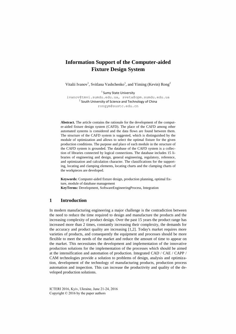
4.3 Working With the Libraries
The main functions of the developed database are the accumulation, updating, storage
and provision of information to implement the design stages. A physical model of the
proposed database is implemented with the help of the database management system
MySQL. Working with database within the frames of the proposed CAFD is conduct-
ed both at the program level (provision with the information on the needs from the
calculation modules), and at the level of user interface (editing data in the tables). The
latter is implemented using a separate module of the database management, which is a
part of the program complex of the CAFD system (Fig. 9).
Fig. 9. The module of database management
The main module of the entire complex is made according to the MDI-interface tech-
nology that provides the ability to open several documents. The call of commands that
allow the user to work with the information is through the main menu. The windows
- 84 -

for the work with the individual libraries are implemented in the form of the subordi-
nated forms that are created within the container – the main form. The user interface
provides access to the database online.
Each command of the submenu provides access to the screen forms, which provide
the users of navigation means in the database, view and editing of the available in-
formation.
When designing the user interface of the screen forms of the control module of the
database, standard components for Windows are used, that provides an intuitive inter-
face.
5 Conclusions
According to the results of the study the necessity of developing CAFD with optimi-
zation procedures is grounded, the use of which will shorten the term for the produc-
tion planning.
The structure of the developed CAFD includes not only conventional design stages,
which are implemented as individual modules. The key difference of the proposed
structure is the module of optimization, the implementation of which will generate the
most advantageous variants for the fixtures.
The information support of the design process is performed by the developed data-
base, the model of which covers the whole range of relevant information: of produc-
tion, general engineering, regulatory, reference, and optimization and calculation
character. According to the results of the analysis the connections of the calculation
modules are established with the tables of the database.
The further work is directed to replenish the information storage of the databases,
rank and improve data flows and logical relationships between them in the function-
ing of CAFD, the development of algorithms and methods of the automated synthesis
of the fixtures and their multicriteria optimization that would ensure effective interac-
tion with the computer-aided systems of the design and production orientation.
References
1. The Future of Manufacturing: Bringing the real and virtual world together,
http://w3.siemens.com/topics/global/en/industry/future-of-manufacturing/Documents/
feature-infografik/all/en/index.html?stc=wwcg102138#/conclusions/469.
2. Bi, Z.M., Lang, S.Y.T., Verner, M., Orban, P.: Development of Reconfigurable Machines.
Int J. Adv Manuf Techol, 39, 1227–1251 (2008).
3. Karpus, V.E., Ivanov, V.O., Kotliar, O.V., Minenko, D.O., Ivanova, M.S.: Intensification
of Manufacturing Processes. Sumy State University, Sumy (2012) [in Ukrainian].
4. Bi, Z.M., Zhang, W.J.: Flexible Fixture Design and Automation: Review, Issues and Fu-
ture Directions. Int. J. Prod Res, 39, 2867–2894 (2001).
5. Nixon, F.: Managing to Achieve Quality and Reliability. McGraw Hill, Maidenhead
(1971).
6. Rong, Y., Zhu, Y.: Computer-Aided Fixture Design. Marcel Dekker, New York (1999).
- 85 -

7. Karpus, V.E., Ivanov, V.A.: Universal-Composite Adjustable Machine-Tool Attachments.
J. Rus Eng Res, 28, 1077–1083 (2008).
8. Boyle, I., Rong, Y., Brown, D.: A Review and Analysis of Current Computer-Aided Fix-
ture Design Approaches. Int. J. Robotics and Computer-Integrated Manufacturing, 27, 1–
12 (2011).
9. Rong, Y., Huang, S.H., Hou, Z.: Advanced Computer-aided Fixture Design. Elsevier Aca-
demic Press, New York (2005).
10. Nee, A.Y.C., Senthil Kumar, A., Tao, Z.J.: An Advance Treatise on Fixture Design and
Planning. World Scientific, Singapore (2004).
11. Rong, Y.: Chapter 4. Computer-Aided Modular Fixture Design. In: Leondes, C.T. (ed.)
Computer Aided and Integrated Manufacturing Systems. Vol. 4: Computer-Aided Design /
Computer-Aided Manufacturing (CAD/CAM), pp. 103–170. World Scientific, Singapore
(2003).
12. Nee, A.Y.C., Whybrew, K., Senthil Kumar, A.: Advanced Fixture Design for FMS.
Springer-Verlag, London (1995).
13. Hargrove, S.K., Kusiak, A.: Computer-aided Fixture Design: A Review. Int. J. Prod Res,
32, 733–753 (1994).
14. Zholtkevych, G.: Computer-aided Tooling: Theory and Practice. Tehnica, Kyiv (1998) [in
Ukrainian].
15. Kang, X., Peng, Q.: Recent Research on Computer-Aided Fixture Planning. J. Recent Pa-
tents on Mechanical Engineering, 2, 8–18 (2009).
16. Wang, H., Rong, Y., Li, H., Price, S.: Computer-Aided Fixture Design: Recent Research
and Trends. J. Computer-Aided Design, 42 (2010), 1085–1094.
17. Karpus, V.E., Ivanov, V.A.: Choice of Optimal Construction of Modular Reusable Fix-
tures. J. Rus Eng Res, 32, 213–219 (2012).
18. Karpus, V.E., Kotliar, O.V., Ivanov, V.O. Optimization of Manufacturing Processes of Ro-
tational Parts, NTMT, Kharkiv (2012) [in Ukrainian].
- 86 -