information architecture design for the electricity … faculteit...information architecture design...
TRANSCRIPT

Delft University of TechnologyMSc Engineering and Policy Analysis
EPA 2941 Master ThesisAugust 2009
St.Nr. 1385216
Irelia Hiromi Valenzo Aoki
Information Architecture Design for the Electricity Distribution Network


Dr. Rolf KünnekeDr. Theo FensDr. Jan van den Berg
Chairman:First Supervisor:
Second Supervisor:

Outline
Page
List of Figures ...................................................................................................................................i List of Acronyms ..............................................................................................................................i Preface ...................................................................................................................................ii Executive Summary...................................................................................................................... iii Chapter 1. Problem Description .......................................................................................... 1 1.1. Problem Definition ...................................................................................................... 1
1.1.1. Background .............................................................................................. 1
1.1.2. Problem Statement ............................................................................... 2
1.1.3. Demarcation of the Problem ................................................................ 3 1.2. Relevance of the Problem .......................................................................................... 4 1.3. Research Objective and Research Question........................................................ 5 1.4. Research Methodology............................................................................................... 5
Chapter 2. The IA as a Guideline in a Transformation Process ............................... 7 2.1. General Concept of Enterprise Architecture........................................................ 7 2.2. Enterprise Architecture Frameworks ..................................................................... 9 2.3. The Required Elements to Build the Information Architecture .................. 10
2.4. Conclusions ................................................................................................................. 12 Chapter 3. Overview of the Electricity System .............................................................. 13 3.1. The Electricity Value Chain ................................................................................... 13 3.2. The Technical and Economic Subsystems of the Electricity System ........ 14
3.3. Conclusions ................................................................................................................. 15 Chapter 4. The Transition in the Distribution Network ............................................ 16 4.1. Technological and Institutional Context ............................................................ 16
4.1.1. Distributed Generation ...................................................................... 16
4.1.2. Ownership Unbundling ..................................................................... 20
4.1.3. Relationship between Distributed Generation and Unbundling ...... 21 4.2. Enabling Technologies in the TO-BE DN........................................................ 22
4.2.1. Smart Metering................................................................................... 22
4.2.2. Other Enabling Technologies............................................................ 24
4.3. AS-IS Situation: The Passive Distribution Network ....................................... 25
4.3.1. Physical Sub-System of the AS-IS Network....................................... 25
4.3.2. Economic Sub-System of the AS-IS Network.................................... 29
4.3.3. Information in the AS-IS Network..................................................... 30 4.4. TO-BE Situation: The Active Distribution Network ...................................... 30
4.4.1. The Concept of a Smart Grid ............................................................. 30
4.4.3. The Active Network ........................................................................... 32
4.4.4. Physical Sub-system of the TO-BE DN ............................................ 33
4.4.5. Economic Sub-system of the TO-BE DN ......................................... 35
4.4.6. Information in the TO-BE DN.......................................................... 36 4.5. Conclusions ................................................................................................................. 37
Chapter 5. Design of the IA for the Distribution Network........................................ 40 5.1. Preliminary Phase ...................................................................................................... 40
5.2. Phase A: The Architecture Vision for the Distribution Network................. 41 5.3. Phase B: The Business Architecture of the Distribution Network ............. 42
5.3.1. Entities that shape the electricity system .......................................... 42
5.3.2. Functions in the Distribution Network ............................................. 44

5.4. Phase C: The Information Systems Architecture ............................................. 46
5.4.1. Information Architecture ................................................................... 47
5.4.2. Applications Architecture................................................................... 50 5.5. Conclusions ................................................................................................................. 51
Chapter 6. Reflection ............................................................................................................ 53 6.1. Contribution ................................................................................................................ 53 6.2. Assumptions ................................................................................................................ 54 6.3. Constraints ................................................................................................................... 54 6.4. Further Development................................................................................................ 54
Chapter 7. Conclusions and Recommendations........................................................... 56 7.1. Conclusions ................................................................................................................. 56
7.1.1. The Value of an Information Architecture......................................... 56
7.1.2. The Elements to Deduct the Relevant Information in the System ... 56
7.1.3. Using the IA Concept in the Case of the Distribution Network ....... 56
7.1.4. The Design Principles for the IA ....................................................... 57
7.1.5. Entities as Building Blocks for the Information Architecture........... 57
7.1.6. Functions as Building Blocks for the Information Architecture ....... 57
7.1.7. Depiction of Information Used in the Distribution Network ........... 58
7.1.8. Information Applications ................................................................... 58 7.2. Recommendations ..................................................................................................... 58 7.2.1. General Recommendations for the Development of an Information-
Architecture ....................................................................................................... 58
7.2.2. Recommendation for DSOs ............................................................... 59
7.2.3. Recommendation for Policy Makers and Regulators ........................ 60 References ................................................................................................................................ 61 Appendix I. The ADM Development Cycle......................................................................... I Appendix II. Institutional Design of the Liberalised Electricity System.................... II Appendix III. General Description of the Electricity System in the Netherlands ....III Appendix IV. Technical Characteristics of the Distributed Generation Technologies IV Appendix V. Transactions in the Electricity System with the Presence of Distributed Generation.................................................................................................................V Appendix VI. Analysis of the DG Capabilities to Provide Network Services ............VI Appendix VII. Business Model in the TO-BE DN .................................................. VII Appendix VIII. Critical Technical Functions of the Electricity System .............VIII Appendix IX. Questionnaire for Validation .........................................................................IX

i
List of Figures
Page
Figure 1: Thesis Structure............................................................................................................... 6 Figure 2: Positioning of this thesis in the enterprise architecture model. ............................... 8 Figure 3: ADM Development Cycle (TOGAF 2009).............................................................. 10 Figure 4: Schematic representation of the problem and position of the Information-Architecture ..................................................................................................................................... 11 Figure 5:The Value Chain Approach and the Liberalisation Process (Fens 2008-2009) .... 13 Figure 6: Flows within the value Chain (Fens 2008-2009)...................................................... 14 Figure 7: Basic Installation of the Meter (Netherlands-Standardization-Institute 2007).... 22 Figure 8: The Electricity System (Gomez-Exposito 2009) ..................................................... 26 Figure 9: The elements o fan automation system (Strauss 2003) ........................................... 28 Figure 10: Strauss Basic architecture of the electricity system automation.......................... 29 Figure 11: Representation of the AS-IS Automation System.................................................. 29 Figure 12: Structure of an Active Network. Modified from (Advisory_Council 2008) ...... 34 Figure 13: Representation of the Automation System in the TO-BE DN. The elements are extended towards the low voltage network................................................................................. 35 Figure 14: Entities of the system in the AS-IS situation.......................................................... 42 Figure 15: Entities in the system in the TO-BE situation ....................................................... 43 Figure 16: Functions of the Distribution Network in the AS-IS and in the TO-BE situation ............................................................................................................................................ 46 Figure 17: Information Exchange in the AS-IS situation (energy billing)............................. 49 Figure 18: Information exchange in the TO-BE situation (Use-of-system charges)........... 49 Figure 19: Components of the ICT System............................................................................... 50 Figure 20: Transactions within the electricity market in presence of distributed generation including the Balancing Market (van Werven and Scheepers 2005)..........................................V Figure 21: Overview of the transactions in the electricity market including the balancing and the ancillary services market ....................................................................................................V Figure 22: Business model of the TO-BE DN. The DSO creates new revenue sources and reduces expenditures through active network management................................................... VII List of Acronyms ADM Architecture Development Method DG Distributed Generation DN Distribution Network DSO Distribution System Operator IA Information Architecture ICT Information and Communication Technology RES Renewable Energy Resources TOGAF The Open Group Architectural Framework TSO Transmission System Operator VPP Virtual Power Plant

ii
Preface
This master thesis is the result of a work of five months in the section of Economics of Infrastructures, in the Faculty of Technology, Policy, and Management of the Technical University of Delft. The idea of designing an IA for the electricity distribution network came form my curiosity in combining different fields and the current research work of Dr. Theo Fens and Dr. Rolf Künneke. I am really enthusiastic in trying the interfaces of different areas of knowledge, and even though ICT and electricity are not very distant fields, they are not combined that often. Besides, my bachelor studies were purely technical, and the idea of trying a research in the Economics of Infrastructures department was challenging for me. Again, I decided to do so because it was interesting to try more in depth a different field of study. This thesis also represents the finalization of my master studies on Engineering and Policy Analysis. Therefore, I would like to acknowledge the people that contributed to the fulfillment of this project, and also to all the people that supported me during these two years of study. First of all, I would like to thank the advice, patience and great willingness to help of my graduation committee. Dr. Theo Fens, who was my first supervisor, devoted valuable time making detailed reviews of my thesis. I appreciate his knowledge in the subject, but moreover his advices on how to perform my work. His advices helped me during the elaboration of this thesis, and I am sure they will help me in my entire professional life. Dr. Rolf Künneke, the chairman of my committee, was really helpful during the initial stage of my research, while searching for the topic and clarifying initial concepts. His orientation at that stage was decisive for the success of my project. Dr. Jan van den Berg, who was my second supervisor, encouraged me all the time to abstract the real essence of the things I was researching, and showed me the great value of making the things simple and concise. Besides, I would like to thank the illustrative discussions I had with other professors and PhD students of the university, especially during the initial stages of my research. They helped me a lot to structure my ideas, to generate new ones, and to find valuable bibliography. I want also to thank all my EPA classmates. They were a great support both during the courses and during the thesis development. Especially during the thesis time, Shahnaz helped me a lot to organize my activities, and cheer me up all the time. Fokke always showed interest on my topic, and sometimes, he even renewed my motivation and curiosity on my own work. I also want to thank Anders for his great contribution making my thesis more beautiful. Apart from mentioning the persons who directly contributed to my thesis, I want to take the opportunity to thank my friends for their affection and support. During my master studies, I learned a lot from them. They encourage me, and provided me very nice experiences that I will always keep in my mind. Last but not least, I want to thank to my family. Gracias papá, mamá, Yukiko y Naomi por todo su amor y apoyo incondicional. Gracias a los tíos y tías que siempre me hicieron sentir querida y recordada, y gracias a las primas por animarme aun estando lejos.

iii
Executive Summary
Problem Definition Policy goals of sustainability, security, and competitiveness are driving a major transformation in the electricity sector in Europe. In this transformation, numerous institutional and technological changes are taking place, and are challenging the present characteristics of electricity infrastructure. To accommodate all these changes, electricity networks might evolve towards a more “intelligent” way of operation. Intelligence in this context refers to the capacity of using information to make decision, and to develop new functionalities. In other words, in the future, electricity networks might increase their usage of information, and might add an information-layer to their current infrastructure. In this thesis we focus on two specific events: the process of unbundling, which is an institutional change, and the integration of distributed generation (DG), which is a technological change. As mentioned before, these events require the utilization of more information because more transactions are carried out in the system. As information is not tangible, it is useful to conceptualize and represent it in order to manage it. For instance, in the case of electricity network operators, a clear depiction of the information needed to develop new functionalities might guide a better deployment of supporting Information and Communication Technology (ICT) infrastructure. At this point is useful to introduce the concept of Information-Architecture, as a “formal description and structuring of the information and the ICT systems that support the activities of an organization”. This concept has been developed after many enterprises integrated ICT systems in their activities. This thesis proposes to apply the concept of IA to the case of the electricity networks. The context around in the electricity networks is diverse. For instance, unbundling between large energy producers and transmission networks has been already implemented in different places; conversely, unbundling between retail activities and distribution networks is rarer. On the other hand, DG is already largely present at high voltage levels, but practically inexistent in the low voltage distribution network (DN). As we may infer, in the near future, if ownership unbundling and distributed generation keep progressing, the segment of the networks that will suffer major changes is the low voltage distribution network. In comparison to higher voltages networks, where already some usage of information exists, the low voltage network will require the integration of more information systems, because by now there is any information infrastructure there. The visualized distribution network, which adds “intelligence” to accommodate DG is named an “active network”. A development of an IA for this segment would be useful to reach this active network state. This leads us to the formulation of the main research question of this thesis: Research Question: What high level IA for the electricity distribution network fulfills the design requirements imposed by distributed generation and ownership unbundling? Analysis In order to solve this question, we have to understand four elements in the process of transformation of the electricity distribution networks: 1) The baseline (AS-IS) situation of

iv
the network, which corresponds to a passive, vertically integrated into one utility, DN. 2) The target (TO-BE) situation of the network, which corresponds to an active DN. 3) The specific institutional and technology changes which imposes the information requirements, in this case, ownership unbundling and DG. 4) The enabling technologies in a transition towards an active network. Of special importance is the analysis of Smart Metering technology. Once these elements are analyzed, the construction of an Information Architecture (IA) may rely on an architecture framework. In this thesis we based our process design on The Open Group Architectural Framework (TOGAF) recommendations. An architecture framework is a collection of detailed methods and a set of supporting tools that describes the process to develop an architecture. TOGAF includes an Architecture Development Method (ADM) consisting on eight phases. We describe up to the third phase of this cycle to design the process for building an IA for the electricity DN. Process Design Before starting the ADM, it is important to plan the architectural work to be performed. The development of an IA should be shared among different actors with interests in a good performance of the DN in the future. These actors are the Distribution System Operator (DSO), the Transmission System Operator (TSO), Metering Services Companies, Retailers, DG operators, and Regulator. An early consensus among these actors would favor the acceptability and robustness of the architecture. Already in this preliminary phase we can observe some disagreements between the recommendations proposed by TOGAF and the nature of the DSO enterprise. The first step in de design of an IA consists on generating a vision for the DN. This vision should include goals, general principles, stakeholders, and drivers. The business goals are the ones established by policy makers, like preserving security of supply, providing a good quality of service, and favoring competition. The general principles are specific institutional arrangements created to regulate the performance of the DSO. The drivers are the events of ownership unbundling and integration of DG in the low voltage network. The stakeholders are the actors that interact with the DN. The second step consists on defining the organization and structure of the distribution business. Here, the basic building blocks to depict functions of the DN are defined. These building blocks are the entities and the critical functions. An entity is an actor or group of actors that perform a single function within the market institution of electricity, actors from the legal institutions, or actors in charge of administrating information. The critical functions are those performed within the DN to preserve the flow of electricity and the economic flow to sustain the system. The last step consists on identifying the information flows, information sources, and types of information utilized by the DSO to support its critical functions. Information flows are mainly present between market entities: TSO, DSO, Metering Services Entities, Retail Companies, DG Operators, and consumers. But there is also an information loop between the customers, regulator and the regulated entities. The main information sources are the metering devices; an important development and an enabler for future functions is the Smart Meter, which provides disaggregated information near the customer end. The types of information can be classified in three categories: information related to the physical flow of electricity, information related to economic transactions, and information to identify entities and devices in the system.

v
Conclusions • The IA is a valuable representation, which favors communication between
stakeholders, supports management of information, and assists the transformation process towards an active network
• There is a discrepancy between the focus of architecture frameworks and the nature of DN business. This brings some discrepancies in applying IA concept.
• DG and ownership unbundling determine the design principles for the IA. Regarding DG, it is imperative to know specific technical characteristics (type, amount, location). In the case of unbundling, is important to know how information can affect the already established institutions in this sector.
• The basic building blocks for an IA are entities forming the electricity sector and functions required by the DN
• For defining entities, a functional approach is useful to deduct information flows. • Market, legal, and information administration entities should be included in the IA. • A major difference between the AS-IS and TO-BE situation is the additional
functions that the DSO must perform. These additional functions are less critical in terms of time constraints, but still necessary in terms of technical scope.
• A formal methodology for depicting information flows, information sources and types of information must be employed to generate the IA
• Information systems should provide governance into the system. For this, is important to maintain a proper interaction between economic and physical transactions facilitated by the DSO.
• Different types of information, requires different communication links. The ones with higher time criticality require a real-time communication technology, while non-time critical functions allow for a “slower” communication technology.
Recommendations For building an IA • Enrich the suggestions given by architectural frameworks with best practices in
similar (network) infrastructures. • In addition to a process-oriented architecture, an output-oriented architecture
should be used to formulate a clear depiction of information. • Early confrontation of the architectural design with the relevant actors (DSO, TSO,
Metering Services, Retailers, DG operator, and Regulator) favors a more robust design
For DSOs • Develop an IA to contribute to a better (and more cost-effective) functioning of
the whole system • Elaborate an early and high level planning of the DG to be connected to the
network, as information supporting infrastructure depends on it. • Share the IA with regulator to develop information codes that support other
institutional arrangements. • Use an IA to optimize the exchange of information, and to anticipate problems
related to security, incompatibility or access to information. For Regulators and Policy Makers
• Prepare for the transition towards an active network by clearly defining entities in the system and by developing information institutional arrangements.
• Put special attention on the deployment of Smart Metering. Access rules should be clear and adequate communication links to this device should be developed.
• Favor standardization of information exchange, so the costs incurred by unbundling are minimized

1
Chapter 1. Problem Description
Nowadays, electricity systems are under a major process of change, pursuing for secure, sustainable and competitive energy provision. Liberalisation-which includes unbundling of utilities-, larger proportion of renewable energy technology, and a tendency towards more decentralized generation technologies, are clear trends in the transformation process of this industry. In this transforming environment, it is expected a higher integration of Information and Communications Technology (ICT) to make the operation of the electricity systems suitable for the expected future conditions. The focus of this thesis is the Distribution Network (DN), particularly the low voltage part, because the integration of ICT will be of special importance in this segment of the system. We analyze the DN functioning, its expected transformation, and its future information requirements. To make this analysis, we propose to employ the concept of Information Architecture (IA). This brings the main idea to be tacked in this thesis: how to apply the concept of IA and how to apply it to the DN case. To develop this idea, this first chapter has the intention to clarify the problem under study: the design of an IA for the low voltage electricity DN. For this purpose, this chapter is composed by four sections. In the first section (section 1.1), we present the problem statement (“what the problem is”), and delimitate the problem. In section 1.2, we discuss the relevance of the problem (“why it is important”). In section 1.3, we state the objective and the research question to be solved. And finally, in section 1.4, we explain the methodology to be followed (“how are we going to tackle the problem”). 1.1. Problem Definition
1.1.1. Background
Nowadays, policy goals for energy provision are driving a transformation of the electricity sector, in which big technical, economical, and social challenges are present. This thesis is focused on the Distribution Network (DN), because relevant technological and institutional changes are currently being carried out around it. One relevant event is the technological change caused by the appearance of Distributed Generation (DG)1. Usually, DNs were designed as passive, radial networks with a structure that reflected the need of conducting electricity (together with the transmission network) from centralized, large scale energy generators towards end users in a top-down fashion. However, with the increasing number of DG and renewable energy sources (RES) directly connected to the DN (i.e. large Combined Heat and Power (CHP) plants, and wind farms) the traditional conception of energy production is being modified. In consequence, the operation of the DNs is expected also to be adapted to cope with this different energy production that resembles more a network fashion. Specifically talking about the DN, the tendency of installing DG is likely to reach the low voltage segment. Technical developments suggest the possibility that a large share of electricity is generated by micro-generator systems at the consumer end (i.e. systems comprising micro CHP and photovoltaic cells at households). This would imply feeding
1 This term will be elaborated on in section 4.1.1

2
electricity at the most external end of the network. This new structure would completely reverse the top-down conception of energy generation and oppose centralized management scheme, confronting the traditional designs of DNs. Another relevant event is the institutional changes produced within the liberalization process, which implies unbundling of utilities. Unbundling entails the separation of -originally fully integrated- electricity utilities into “functional segments” managed by independent actors. The main intention of unbundling is to make a differentiation between segments with characteristics of natural monopolies that must be regulated (the networks) form those with a commercial nature that must be operated under market environments. Thus, the implication of unbundling is that DN operation must be separated from generation, trade and retail activities. Besides, unbundling incorporates a clear separation between the transmission network and DNs, although they jointly compound the physical core of the electricity system, “the network”. Evidently, the fully unbundled envisaged future of the electricity sector implies that the operation of the DN and its role within the electricity system is modified.
1.1.2. Problem Statement Technical and institutional changes impose new challenges for the operation of the DN. As a response to these challenges, many conceptualizations of how the future DN should be in the future have been developed. One generalized vision is the one of an “active” network2, in which active management of the elements of the network is performed to achieve higher control, coordination, and to develop new functionalities. Active management implies the handling of more and different information. For example, the future Distributed System Operator (DSO)3 should have, at least, a registry of the DG connected to the network and should use this information to ensure the proper functioning of the whole system. Active management is possible thanks to the existence of enabling technologies that allow a different use of information. ICT technologies that makes feasible the exchange and processing of information, and advances in metering and sensors devices that generate the necessary data to analyze the system, are examples of today’s enabling technologies. Restating the previous reasoning, we can say that a main difference between the traditional DN and the future conceived DN is the type of information used, and the way it is handled. To improve the functioning of the DN different (and more) information will arise with the integration of new elements in the network; the way of using this information will allow for creating new functions, new modes of operation, and new transactions among different actors. Evidently, in order to arrive at the conceptualized future DN, the necessary “information sources” in the network, and the ICT systems that facilitates information exchange should be deployed. In this deployment, a high-level guideline representing the information required in the future DN would be a useful tool to effectively steer the transformation of the DN.
2 This term reflects the opposition to the traditional passive characteristic of the distribution network. This concept will be further elaborated on section 4.4 3 The DSO is the actor in charge of the DN

3
Here, it is useful to introduce the concept of Architecture, as described in the American National Standards Institute/Institute of Electrical and Electronics Engineers (ANSI/IEEE) Std 1471-2000. “Architecture is the fundamental organization of a system, embodied in its components, their relationships to each other and the environment, and the principles governing its design and evolution.” Using the previous idea, and applied to the case of the electricity system, we can say that an IA would be a useful tool to conceptualize the information elements of the electricity system, and to assists in the transformation process of this system. We can understand the concept of IA as a formal description of how the information is structured and organized between different actors/elements involved in the operation of the energy value chain in which the DN is one of the actors. It is a conceptualization of DN elements, their inter-relationships, and the principles and guidelines governing ICT systems used for the management of this network. This led us to the problem statement of this thesis: It is necessary the design of an IA for the future DN, which is the one operating in presence of DG connected to the low voltage (LV) network and under ownership unbundling, to favor its evolution.
1.1.3. Demarcation of the Problem This thesis is limited to analyze at high-level how the concept of IA can be applied to the DN operations. Although the terms used refer to general concepts of electricity systems, it is necessary to constraint the object-under-study to support the assumptions made. First of all, the analysis will be centered on the information flows in the electricity system. Specifically, on the information between functional segments to accomplish the distribution function. A second consideration is that the vision of the “future” DN corresponds with the current visions formulated in Europe. It is of special importance the vision formulated in the Strategic Deployment Document for Europe’s Electricity Networks of the Future (Advisory_Council 2008), specifically regarding “Deployment Priority #5: Active Distribution Networks”. This vision depicts the DN in a timeframe of 10 years between 2010 and 2020. A third consideration is that we will use the specific case of the Netherlands to support some specific assumptions. This delimitation is useful to give a practical basis to some ideas and concepts, and, in further research, it may facilitate the validation of the proposed. A fourth consideration is regarding the technological and institutional context. DG and unbundling are important events in the Netherlands, and are in an advanced state in this country compared to other EU countries that are under a similar reform process. For this reason, these two events are the ones considered in the analysis of the context. Finally, we will be centered in the low voltage segment of the DN, because deep differences compared to the present situation are expected there. By now, certain degree of active management has been deployed up to the medium voltage network, to handle the already significant amount of DG connected at this level. In contrast, today, at the low voltage level, there is any system with DG connected4, and therefore, there are no active 4 With the exception of test facilities or prototype projects

4
management systems at all, even though many enabling technologies, like smart metering, are already present. 1.2. Relevance of the Problem
Based on the above description, and on literature on the design of Enterprise Architecture (Minoli 2008), we can list the following reasons to consider the design of an Information Architecture:
1) It enables communication among stakeholders; 2) It creates a transferable abstraction of the system and an environment description; 3) It facilitates an early design description; 4) It is an instrument that assists the governance of the transformation process.
In the next paragraphs, these reasons are explained, and it is important to note that these motivations are interrelated. It enables communication among stakeholders Electricity networks are the core of the electricity infrastructure, and therefore the meeting point of many actors. Indeed, the operation of the network has huge impact on the overall performance of the industry; therefore, an optimal operation is highly desirable. For instance, depending on the design of the distribution network, larger entrance of DG could be favored or prevented; this influences the degree of competitiveness and sustainability of the overall sector. An IA may become an accepted representation of required information exchange between stakeholders to support distribution of electricity. In this case, this accepted representation would unify visions and concepts. Moreover, it would help the stakeholders to understand the information present in the system, and use it to take a decision that complies with the overall strategy of the sector. An accepted representation would also provide useful insights for policy makers. It creates a transferable abstraction of the system and an environment description The final deliverable in the process of developing an IA for the DN is a concrete, transferable representation of the desired state of the DN in the future. It is important that this representation is transferable because then many stakeholders can check the adequacy of the design based on its compliance with defined objectives, interests, and with the environment. This checking is of vital importance before the actual implementation of ICT systems is carried out. It facilitates an early design description An IA can be used as a guideline for implementing the ICT systems in the electricity networks. Having a guideline always reduces uncertainty and, therefore, helps in managing costs. Besides, an early design description is a useful tool for making better decisions regarding investments or changes in the infrastructure. It is an instrument that assists the governance of the transformation process

5
It is explained in the previous paragraphs that the IA can enable communication among stakeholders, can create a valid representation for the desired state on the DN, and can support investment and implementation decisions. Consequently, the IA can be used as a roadmap to reach the target state, assist the transformation process, and therefore increase the possibilities of achieving the visualized DN. This reason is the most important one to develop an Information-Architecture. 1.3. Research Objective and Research Question
Objective
To apply the IA concept to the analysis of the low voltage electricity distribution network, when it operates under an environment of ownership unbundling and distributed generation of electricity.
Research Questions
The main research question to solve in this thesis is:
What high level IA for the electricity distribution networks fulfills the design requirements imposed by distributed generation and ownership unbundling?
To solve this question, the following sub-questions are formulated:
• What are the approaches to describe the technical and institutional characteristics of electricity networks?
• How can the concept of IA be applied for analyzing the information of future electricity distribution network?
• What are the design requirements for an IA that supports the operation of distribution networks, under the conditions of decentralized generation and ownership unbundling?
• How can an IA for the electricity distribution network, which fulfills the design requirements imposed by distributed generation and ownership unbundling, be designed?
1.4. Research Methodology
The methodology used was desk research. The procedure followed during this research is reproduced in the structure of this thesis, and each chapter answer different sub-questions posted in this first chapter. First of all, in Chapter 2, we structure the problem based on the IA concept. Then, in Chapter 3, we provide an overview of the electricity system in order to illustrate the context of the analysis, and to establish the basic concepts used in further chapters. In Chapter 4, we elaborate on the necessary elements to be analyzed in order to conceptualize the information used in the electricity systems. In Chapter 5, we describe the design process to construct the Information-Architecture. In 0 we present the reflections on the research done, and we suggest further developments to enhance the analysis. Finally, in Chapter 7, we conclude, and provide the answer to the main research question. In the Figure 1 below, we provide a schematic representation of the previously described outline. The research phases are listed in the fist column; the thesis chapters associated to each research phases are presented in the second column; finally, the research questions

6
related to the corresponding thesis chapters and research phases are presented in the last column.
Thesis Chapter Research Question
Problem Description
Information-
Architecture Concept
Overview of the
Electricity System
The Transition in the
Distribution Network
Design of an
Information-
Architecture for the
Distribution Network
Conclusions and
Recommendations
Analysis
Problem formulation
Conceptualization
Conclusions
1
2
3
4
5
6
7
Reflection
How can the concept of Information Architecture be applied for analyzing the information of future
electricity distribution network?
Research Phase
Process Design
What are the design requirements imposed by ownership unbundling and distributed generation for an information-architecture of the electricity
distribution networks?
What are the approaches to describe the technical and institutional characteristics of electricity
networks?
How can an information-architecture for the electricity distribution network, which fulfills the design requirements imposed by distributed
generation and ownership unbundling, be designed?
How is the overall result of this research?Reflection
Figure 1: Thesis Structure

7
Chapter 2. The IA as a Guideline in a Transformation Process
In the future, Distribution Networks (DNs) will need to handle different information and to integrate ICT to confront the challenges imposed by institutional and technological changes. This need for including an “information layer” in the electricity infrastructure presupposes a transformation of the system. And a useful tool in this transformation is an Information-Architecture, which is intended to represent the information in the future distribution infrastructure. As we can see, we are dealing with a complex problem: how can the concept of IA be applied for analyzing the information of the future electricity DN? In order to solve this question, we have to clarify the concept of Information-Architecture, and to situate it among the necessary elements related to the distribution network transformation process. This helps us to structure our research, and, that is why, this chapter is considered the conceptualization phase. As the concept of IA is not unique and is very abstract, we support its definition with the explanation of the broader notion of “Enterprise Architecture” and with the explanation of “Enterprise Architecture Frameworks” that support the construction of different architectures. This will be made in sections 2.1 and 2.2. In the last section, section 2.3, the general process for constructing an IA is explained, and is linked to the case of the electricity DN. This section structures our problem under research, and provides a basic framework illustration on the elements that must be analyzed in subsequent chapters. 2.1. General Concept of Enterprise Architecture
The following definition of Architecture is given by The Open Group’s Architectural Framework (TOGAF): “Architecture has two meanings depending upon its contextual usage: (1) A formal description of a system, or a detailed plan of the system, at component level to guide its implementation; (2) The structure of components, their interrelationships, and the principles and guidelines governing their design and evolution over time.” The concept of “Enterprise Architecture”, as it name suggests, deals with the description and structuring of an enterprise, but is mainly focused on the analysis of the Information and Communication Technology (ICT) systems that supports the activities of that enterprise. The concept “enterprise-architecture” was developed as a management tool that helped to confront nowadays challenges. For instance, a fast changing environment, and the inclusion of many stakeholders, usually adds a lot of complexity in the operations of enterprises. In these circumstances, the function of the “enterprise architecture” is to provide insights on the enterprise structure and on the way in which information and ICT systems can be used to support new functions. Therefore, the enterprise architecture, is a guideline that helps in the transformation processes that the enterprises require to adapt to its environment (Op't Land, Proper et al. 2009).

8
In the literature related to “enterprise architecture”, the enterprise is referred as any collection of organizations that has a common set of goals (TOGAF 2009). In this thesis, the aim is to apply the concept of enterprise-architecture to the electricity system case, where an electricity system can be seen as a collection of many actors that pursue common goals of affordability, accessibility, acceptability, and reliability of energy provision. Thus, in this perspective, the electricity system is analogous to an enterprise. The electricity system is immersed in a changing environment; liberalization processes and the rapid evolution of technology are driving a transformation. Within this transformation, integration of ICT systems to facilitate both physical and economical flows is imperative. An enterprise-architecture would function as a blueprint for integrating necessary ICT to support electricity system operations. An enterprise-architecture performs different functions, which can be described (formulated) in corresponding (sub) architectures: business architecture, information architecture, (systems/applications) solution architecture, and technology infrastructure architecture (Minoli 2008). This is represented in Figure 2.
Business
Business Architecture
Information Architecture
Solution Architecture
Technology Architecture
Development and/or
Engineering
Operations
Business Requirements
Architecutres/Roadmaps
Architecture Standards
Design Specs
Engineering Specs
Operational Specs
Figure 2: Positioning of this thesis in the enterprise architecture model.
Figure based on Enterprise Architecture Model (Minoli 2008)
According to (Minoli 2008)the business function is a description of all business elements and structures that are covered by the enterprise; the information function is a comprehensive identification of the data, the data flows, and the data interrelations required to support the business function; the (systems/application) solution function aims at delivering/supplying computerized ICT systems required to support the plethora of specific functions needed by the business function; and finally, technology infrastructure function is the complete technology environment required to support the information function and the (systems/application) solution function. The scope of this thesis is limited to develop the enterprise architecture up to the information function. Therefore, the objective is to identify the data, data flows, and data interrelations of the DN, and represent them to build an information-architecture.

9
2.2. Enterprise Architecture Frameworks
There is not a unified definition of what an enterprise-architecture is, nor is there a single method to develop one. Nonetheless, there exist “detailed methods and a set of supporting tools” to develop an architecture, which are called “architecture frameworks”(Minoli 2008). Architecture frameworks help in different aspects of the creation of an enterprise-architecture, either by specifying methods to represent the outputs or by guiding the process to develop them. Nowadays, there are a many architecture frameworks. The top four enterprise-architecture methodologies are the Zachman Framework for Enterprise Architectures, The Open Group Architectural Framework (TOGAF), The Federal Enterprise Architecture, and The Gartner Methodology (Roger 2007). In this thesis, we employ the TOGAF framework because it defines a process methodology which can be directly linked to the definition of enterprise architecture used. This will be explained in the following paragraphs. The core of TOGAF is the Architecture Development Method (ADM) which defines a process to develop an enterprise-architecture; that is, ADM describes how to develop the business architecture, providing guidelines and best practices, but it doesn’t specify the output to be formulated (Op't Land, Proper et al. 2009). The TOGAF/ADM cycle is depicted in Figure 3. In this figure, the various phases composing the development cycle are represented with circles, and these phases can be applied iteratively depending on management requirements (the core of the cycle, represented by the central circle). The description of each specific phase can be found in the Appendix I. This figure also helps us to position this thesis in one of the phases: the Phase C, development of the “Information Systems Architecture”. This phase is elaborated on in Chapter 5. As we may observe, there is a direct correspondence between the notion of enterprise architecture (Figure 2) and the process defined by TOGAF/ADM (Figure 3). This association is the reason to use TOGAF as the architectural framework in this thesis.

10
Figure 3: ADM Development Cycle (TOGAF 2009)
2.3. The Required Elements to Build the Information Architecture
Regardless of the architectural framework used, according to Op’t Land, Proper et al. (2009), the process of developing an IA requires a shared conceptualization among stake holders about: • The as-is situation, which is a baseline or reference situation; • A to-be situation, which is a target situation; • Any constraints that should be met; • Purposes of the enterprise architecture. Translated to our problem under research, the AS-IS situation is the description of the traditional passive DN (prior liberalization process). The TO-BE situation corresponds to the future active DN. The constraints that should be met are the requirements imposed by entrance of DG in the low voltage distribution network and ownership unbundling. Finally, the main purpose of an IA is to assists the transition from the AS-IS network to the TO-BE network. Figure 4 represents the IA role within the problem under research. It schematizes the necessary elements to be considered to create this architecture. This scheme can be interpreted as the conceptualization of our problem.

11
Figure 4: Schematic representation of the problem and position of the Information-Architecture
The main elements around the construction of the IA are:
1. The context: It comprises institutional and technological events having direct impact on the DN. Specifically, the events considered are entrance of DG at the low voltage level of the DN, and ownership unbundling. This context is the driver for a transformation of the DN; consequently, these events frame the information requirements to be fulfilled by the TO-BE DN.
2. The enabling technologies: They are technologies that would make the implementation of an active network feasible. Among them, Smart Metering is especially important.
3. The AS-IS situation of the DN is to be a passive network. For this thesis, we chose this situation that coincides with the traditional design of the electricity system, in which the distribution network conducts passively the electricity coming from the transmission network to the end customers, and is vertically integrated in one utility. Even though this situation is not anymore the nowadays’ situation, we use it as the baseline reference because it was a stable situation during a long time. The characteristics of this as-is situation provide simplicity to the analysis of information changes.
4. The TO-BE situation of the DN is to be an active network, which is the network that integrates DG making use of “active management”, and operates in a fully unbundled environment. This active management presupposes the inclusion of an information layer to the AS-IS infrastructure that allows performing informed decisions, and improving physically and economically the operation of the DN. Even though the future is uncertain, this is a possibility that is found in the literature (European_Communities 1995-2009; Advisory_Council 2008; McDonald 2008).

12
From this conceptualization, it is important to remark that the transition comes from the change in the functions performed, and the way that the critical technical functions are maintained in the TO-BE situation, in contrast with the AS-IS situation. One major difference is the information managed, and functions supported by this information. Besides, the IA is represented as a central element in the conceptual scheme. This is because the IA is considered to be a guideline for implementing the ICT systems of the future (TO-BE) DN. As a consequence, the IA forms the foundation for the transition towards the visualized “TO-BE” state. The IA should be constructed based on the current design of the DN (AS-IS situation), and on an accurate conceptualization of the TO-BE DN. It must be in agreement with the institutional and technical context, and must take into account the enabling technologies that allow the “TO-BE” situation. 2.4. Conclusions
How can the concept of Information Architecture be applied for analyzing the information of future electricity distribution network? The information architecture concept, understood as an element of an “enterprise -architecture”, can be used to conceptualize the relevant information, information flows, information sources and information interrelations of the electricity DN. To use this concept, we can picture the electricity system as an enterprise, and the distribution function as one of the enterprise functions that must be transformed. To build an information-architecture, there are architecture frameworks that provide support either by defining the construction process or by defining the output product. The framework chosen in this thesis is the TOGAF framework, and specifically the ADM development cycle, which gives recommendations on how to build the information architecture. This framework was chosen because the process is fully compatible with the working definition of enterprise architecture used here. The analysis to build and IA for the future distribution network, should include the next elements: The context (the drivers for change), the enabling technologies (those that make the evolution feasible), the AS-IS situation (baseline description of the distribution network), and the TO-BE situation (target description of the future distribution network). These elements provide the indispensable insight of the distribution network situation, and therefore it is possible to deduct the design requirements from them. By linking the definition of information-architecture, the development process given by TOGAF/ADM, and the electricity system situation, we can make a conceptualization of the problem and build an Information-Architecture.

13
Chapter 3. Overview of the Electricity System
At the end of Chapter 2, the elements facilitating the development of an IA were presented. However, before elaborating on these elements, is worthy to present a general overview of the field in which the problem is recognized: the electricity system. With this, the question to be solved in this chapter is “What are the approaches to describe the technical and institutional characteristics of electricity networks?” Presenting the useful approaches to describe the electricity networks, we can define the basic terms used in the following chapters, and provide a panorama of the system described. This chapter is divided in three sections. In section 3.1, the electricity value chain approach is introduced. In section 3.2, the general structure of a liberalized electricity system is explained. Finally, in section 3.3 a general description of the regulatory framework in which the electricity system operates is provided. In this thesis, specific assumptions are based on the Dutch electricity system; therefore, some comments regarding this system are added. 3.1. The Electricity Value Chain
The electricity sector can be depicted using a value chain approach. In this approach, the electricity system can be separated in seven fundamental elements: Production, Trade/PRP, Transmission, Distribution, Metering, Sales, and the final customer. From a regulatory point of view, these elements are the more granular decomposition of the electricity value chain, because further separation would imply significant market distortions; therefore, they can be considered as the basic building blocks for a market design irrespective of utility jurisdiction (Fens, IJsbrandy et al. 2005). In the Figure 5 below, we represent the electricity value chain before and after liberalization of the energy utilities.
Figure 5:The Value Chain Approach and the Liberalisation Process (Fens 2008-2009)
As it can be observed in the previous figure, prior to liberalisation, the electricity utilities were vertically integrated; this means, that all the functions of the value chain were performed by one utility company. After the liberalization, the elements of the value chain are decoupled (or unbundled, see section 4.2.2), mainly to separate the commercial, market based functions (Production, Trade, Metering and Sales) from the regulated monopolistic functions (Transmission and Distribution).

14
For the adequate functioning of the energy value chain, three main flows travel across the entire chain: a physical flow, a monetary flow, and an information flow. The physical flow starts with the production of electricity and ends with the delivery of electricity at the customer site. The monetary flow travels in the opposite direction: it starts with the customer payments, and then covers the upper segments up to the production of electricity, remunerating the service provided in each segment. The information flow does not have a defined structure; it is indeed the purpose of this thesis to represent the information flow under the described conditions. The information flow can be considered as to be an auxiliary flow in order to maintain the other two main flows: the physical and the monetary, as it travels between and within the segments of the value chain, facilitating the proper integration of functions in the value chain. This is represented in Figure 6 below.
Figure 6: Flows within the value Chain (Fens 2008-2009)
3.2. The Technical and Economic Subsystems of the Electricity System
The liberalization process has increased the complexity of the electricity sector. For the proper operation of an electricity system under this regime, new actors, new transactions, and new information flows have appeared throughout the entire value chain. De Vries et al. (2006), describe the basic structure of an electricity system5 as being composed by a technical subsystem, an economic subsystem, and a legal framework which regulates both subsystems and their interactions. In the Appendix II, a conceptual model of the liberalized electricity system is presented.
• The technical subsystem consists of the hardware that physically produces and transports electric energy to customers, as well as the equipment in which energy is consumed: power stations, networks, and consumer equipment. It also comprises the organizations that build, maintain, operate and control the equipment: producers, system operator, network operators, and consumers.
• The core of the economic subsystem is the market, which design varies form country to country to be an organized wholesale market or an over-the-counter market. In general, the market includes bilateral contracts and power exchanges. Also, it includes balancing markets, interconnection and congestion management, and provision of ancillary services, where it is necessary the participation of the system operator and the transmission network managers in these activities.
The legal framework exists at different levels. At regional level, the EU imposes directives (that must be adopted at national level to have effect), regulations (that affect
5 An electric power system is defined as the one controlled by one Transmission System Operator, and usually coincides with the definition of one control area.

15
directly to actors in the electricity industry), and guidelines (both binding and non-mandatory). The government, through the regulator, can create rules for the TSO and the market and network operators (De Vries, De Jong et al. 2006). At national level, in the Netherlands, the Office of Energy Regulation (Energiekamer) is charged with regulating the Electricity Act 1998 and Gas Act. This regulatory body comes under the Ministry of Economic Affairs and operates as a chamber within the Netherlands Competition Authority (NMa) (Energiekamer 2009). Following the EU Directives, the Dutch energy market was liberalized on 1st of July of 2004, under the Electricity Act 1998. Under Dutch laws, from 2011 onwards ownership unbundling of both the TSO and DSO networks will be applied; with this, network operators may not belong to a company that also supplies or produces energy (EnergieNed and Netbeheer-Netherlands 2008). A scheme of the legal framework can be found on Appendix II. As mentioned before, our research takes some assumptions from the specific case of the Dutch electricity system. Hence, it is worthy to have a general overview of the electricity industry in this country. A comprehensive description of this system can be found in the publication from EnergieNed and Netberheer Nederlands (2008). In this thesis, a brief summary is included in Appendix III. 3.3. Conclusions
What are the approaches to describe the technical and institutional characteristics of electricity networks? Today’s electricity network is under a transition process, both regarding technical and institutional aspects. A very useful abstraction of the system, that allows us to understand the situation of the electricity networks at a high level, is the value chain approach. In this approach the electricity system is broken down in functional segments: production, trade, transmission, distribution, metering, sales, and consumption. The value chain as a whole facilitates the flow of electricity (physical flow) and of money (monetary flow). However, an important difference for the institutional design is the characteristics of the segments in which competition can be introduced (production, trade, metering, sales) and the ones that must remain as regulated entities (transmission and distribution). Another approach to conceptualize how the electricity system works breaks it down in a physical sub-system and an economic sub-system. Each sub-system is responsible for maintaining the correspondent electricity flows and economic transactions. It is useful to notice the difference between these two subsystems, because supporting infrastructure should be designed taking into account this. Still, we can associate both approaches by understanding that each segment of the value chain comprises specific economic and physical elements. For instance, consumption is performed physically by the load connected to the network, and economically by the retailers and consumers (customers). As the functional perspective used in the value chain approach provides a high level of abstraction adequate to explain the physical and the monetary flow, we assume that is also useful to explain the third main flow in the system: the information flow. However, in the value chain representation, only the market actors are considered. Then, the consideration of the legal framework in the technical-economic approach enriches the information analysis, as some other institutions (like legislation) are considered. Policy makers and regulators are also relevant actors in the information exchange.

16
Chapter 4. The Transition in the Distribution Network
In Chapter 2 we presented a conceptual view of the elements to construct the Information-Architecture. The objective of this chapter is to explain in detail each of these elements, and, with this, give insights on the problem under research. This chapter forms the first part of the analysis, and provides the basis to deduct information flows in the electricity DN in the next chapter. At the end of this chapter we want to understand what the design requirements for an IA (IA) that supports the operation of distribution networks, under the conditions of decentralized generation and ownership unbundling are. For this purpose, this chapter follows the scheme presented in the Figure 4 in the previous chapter. In section 4.1 we explain the context of the DN. This context encompasses driving events for the transformation of the DN, and therefore imposes the requirements to be met in the future DN. In section 4.2, we present the enabling technologies that make feasible the future vision of the DN. Here, special emphasis is put in the Smart Meter concept as defined in the Netherlands Technical Agreement (NTA) 8130. In section 4.3 we provide a description of the AS-IS situation, which corresponds to a “passive” DN. In section 4.4 we explain the TO-BE vision for the DN, which is based on the one provided by the Advisory Council for European Commission, in its Strategic Deployment Document for Smart Grids. 4.1. Technological and Institutional Context
The first element to analyze is the institutional and technological context that “recently” confronts the long-established design of the DN. It is expected that this context impulses a transition towards a more “intelligent”6 electricity network. In this thesis two events are considered to form the context: the connection of distributed generation (DG) in the low voltage network, as a technological change, and ownership unbundling, as an institutional change. Ownership unbundling and DG may produce important changes in the electricity system, especially in terms of information. As distribution is an embedded actor in a chain, an alteration of information in this segment has also repercussions in the entire value chain. Indeed, the analysis of this information changes is the focus of this thesis.
4.1.1. Distributed Generation The first important event for the DN is the inclusion of DG in the system. In the case of the Netherlands, this event is relevant because it had a great expansion during the last decades7, causing that DG accounts for an important portion of the energy production in this country nowadays. DG is defined as an electric power source connected directly to the distribution network or on the customer site of the meter (Ackermann, Andersson et al. 2001). Pepermans, Driesen et al. (2005), in agreement with the previous definition, identify current generation technologies that can be used for DG: Reciprocating engines, gas turbines, micro turbines, fuel cells, photovoltaic, wind, and other renewable (thermal solar, small hydro, geothermal
6 The notion of intelligence will be further elaborated in section 4.4
7 Here, we refer to the large DG, which is the one connected to the medium voltage network

17
and ocean). A detailed description of the DG technologies can be found in the Appendix III. Based on the connection point, and the capacity, we can classify DG on two groups:
• Large DG: The one connected to the medium voltage (MV) network. • Small DG: The one situated on the customer site of the meter; this is, the DG
connected to the low voltage (LV) network. At present, only large DG has been significantly integrated in the electricity systems, so certain degree of automation is already reached to integrate this type of DG. Optimization processes via forecasts and active control, and the consequent inclusion of information systems, are becoming usual at the MV level. In contrast, small DG is emerging but still is not significantly present, and there is almost no active8 infrastructure at all in the LV network. Only pilot installations for new control systems like the “Am Steinweg” (Germany), “Supply Center East” (Germany), and the “Technology Demonstration Centre” (San Agustin del Guadalix, Spain) are present today (Degner, Schmid et al. 2006). However, the potential value that new functionalities in the LV network provides strong incentive to extend the information systems up to this level. For this reason, the focus of this thesis is the LV segment of the network. In the Netherlands, the development of DG has been largely achieved by installation of CHP at industrial sites, connected to the MV network. This type of generation represents a significant portion of the generation capacity of this country. At the moment, the Netherlands has a larger share of energy generated in a decentralized way, compared to other countries in the EU. In 2007, 30.9 billion KWh were produced in cogeneration plants, this is approximately 26% of the total energy consumed (EnergieNed and Netbeheer-Netherlands 2008). Government policies were determinant for the expansion of DG in the Netherlands. The growth of CHP goes back to the 1970s and 1980s, when connection of industrial CHP to the electricity grid was allowed without charges, and these industries were provided with cheap natural gas for cogeneration (Verbong and Geels 2007). From 1989 to 2004, major changes in the formal rules favored a faster expansion of DG. The Electricity Law at that time enforced separation of production and distribution, introduced market mechanisms for the supply side, and created energy distribution companies, which were allowed to generate electricity on a small scale. DG came mainly from industrial CHP, but also from district heating and horticulture(Verbong and Geels 2007). Later on, environmental concerns also promoted CHP diffusion. Dutch policies considered CHP as an important instrument for CO2 reductions. In consequence, large part of the energy was produced outside the centralized scheme, although some difficulties appeared to allow energy feedback into the grid(Verbong and Geels 2007). It is important to note, as in the case of the CHP expansion in the Netherlands, the decisive role that governmental policies and formal rules had in the inclusion of DG in the electricity system. Current European directives for promoting renewable energy sources and energy efficiency improvements (i.e. RES directive and CHP directive) suggest the desirability of expanding DG, and therefore it is likely its inclusion in the LV network in the future.
8 The notion of active network will be extended in section 4.4

18
In the following paragraphs we explain different impacts that DG may have in the DN. This analysis is useful to deduct the functionalities that should be added (or kept) in the future in the DN.
4.1.1.1.Technical Impacts of DG in DN Because the DN was not designed to accommodate electricity generation, DG may have different positive or negative impacts on the performance of the DN. This largely depends on the structure of the distribution system and the characteristics of the DG connected. The effects of large DG and small DG may be different, and the level of impact varies depending on the penetration level. As large DG is the one already under higher development, most of the studies are centered on this type of generation. In the literature, mainly five effects are analyzed while studying the inclusion of DG into the network: voltage level, anti-islanding/loss of main protection, fault level, power quality, and network stability. The first effect is on the voltage level of the DN, which should be maintained within certain limits. For instance, in the residential networks in the Netherlands, the voltage should stay in a range of 230V +/-5% during normal operation (System and Network Codes developed and uphold by the Energiekamer). Large DG may have significant effects on the voltage level (Bayod-Rújula ; Hadjsaid, Canard et al. 1999; Pepermans, Driesen et al. 2005; Lopes, Hatziargyriou et al. 2007). This may be alleviated if the generation of power by DG is smaller than the consumption in this power grid (Landsbergen 2009), or by upgrading transformers for improved voltage control(Bayod-Rújula). However, in the case of small DG (specifically mCHP), many studies indicate that large penetration can be accommodated in the LV network without causing voltage rise effects; only negative effects are expected if energy is exported during low demand, in rural networks or very high concentration of mCHP (Landsbergen 2009). As a result of the concerns on voltage level, we can deduct that this parameter is an important one to measure in a network with DG connected to it, especially during peak and low loads. Besides, in order to manage DG, and make the production to follow the electrical load, it is important to have disaggregated information about the power produced and the consumption at every moment within the network. These measurements are new information to be managed in the network. The second recognized effect is the islanding effect/loss of main (LOM) protection. Islanding is defined as “any situation where a section of electricity network containing generation becomes physically disconnected from the distribution network or user’s distribution network, and one or more generators maintain a supply of electrical energy in that isolated network (PV-Upsale 2007)“. This islanding effect can be intentional (when it is desired a self-sufficient operation) or unintentional (if the network is disconnected because of a network fault, but the DGs continue operating). Unintentional islanding may be dangerous and unsafe for personnel, equipment, and may produce problems in overall operation of the network (Landsbergen 2009). To prevent unintentional islanding, loss of main protection should be installed in the DN to prevent DG from accidentally energizing an electrically isolated section of network. Nonetheless, it should be considered that disconnection of DG, even if it is as a response of an electricity fault, may produce other undesirable effects. For instance, protection

19
mechanisms may also brings tripping of heating services (provided by micro CHP) and may prevent VPP (Virtual Power Plant) operation (Landsbergen 2009). Therefore, it is important to develop information mechanisms that help on discerning the correct moments to disconnect and reconnect DG, taking into account the different affected elements in the network. The third technical impact is related to the fault level. Protection systems are designed for specific fault currents. In the MV DN, synchronous and induction generators directly connected to the grid may significantly affect the network fault levels. Hadjsaid, Canard et al (1999) explain that the fault current is changed because the rotating generators modify the characteristics of the distribution network. This change in fault current also affects the selectivity of protection devices. However, according to Landsbergen (2009), no major issues regarding fault levels are expected in the LV DN, as power electronic interfaced DG units and mCHP contribution to fault levels is small. The fourth technical impact is on power quality. Power quality refers to the degree to which power characteristics align with the ideal sinusoidal voltage and current waveforms, with current and voltage in balance. Thus, strictly speaking, power quality encompasses reliability (Pepermans, Driesen et al. 2005). The main issues of power quality related to the connection of DG are: voltage unbalance (produced if a large amount of mCHPs is connected to one phase of the three phase power system), voltage sags/dips, voltage fluctuation and voltage flicker (may be caused by start/stop operation of the units), harmonics (produced by converter-based DG), and transients (Landsbergen 2009). With the use of advanced power electronics (i.e. IGBT converters, and filters) harmonic issues can be prevented. The last technical impact is on the network stability. Network stability is the capability of the system to return to steady state operation when a disturbance or large changes in the power demand occur. Landsbergen (2009) concludes that mCHP can have negative effects on the network stability, because these systems are not equipped with voltage and frequency control, and they contribute very little to the power system inertia. However, it may only occur if very large amounts of mCHP will be connected and will replace a very large part of the central power supply.
4.1.1.2. Other Impacts of DG in DN In addition to the technical complications that the connection of DG may bring, there are other (non-technical) issues that should be taken into account. First of all, DG has relatively high capital costs per kW installed compared to large central plants (Strachan and Dowlatabadi 2002; Pepermans, Driesen et al. 2005), but DG economic performance can be improved when more DG units are installed in the same region; that is, DG presents economies of geographic concentration (Strachan and Dowlatabadi 2002). Besides, large entrance of DG has consequences on Distribution System Operator’s (DSOs) revenues and expenditures, and it may cause a change in their business models (van Werven and Scheepers 2005).On the one hand, DG may reduce the net electricity flow of the networks, as generation is closer to the end consumer; in this case, DSO could delay the need for investments in the network (van Werven and Scheepers 2005; Cossent,

20
Gomez et al. 2009). On the other hand, DG may imply higher costs for the DSO, as network reinforcements may need to be done in the DN in order to provide open access for DG (van Werven and Scheepers 2005; Lopes, Hatziargyriou et al. 2007)9. Here, information systems should be the reconciling tool for the joint planning of DG and DN in a way that is beneficial for the overall system. Finally, DG adds more transactions to the system operation. Van Werven and Scheepers (2005) depict the transactions in the electricity system in presence of DG, and represent them by adding a new actor, the “DG operator”. This new actor has effects in both physical and economic sub-systems (see section 3.2). In the physical subsystem, new transactions are present between the DG operator and the DSO, and between the DG operator and the energy consumers. In the economic subsystem, economic transactions are present between the DG operator (for large DG or VPP) and the wholesale market, between the DG operator (large DG or VPP) and the balancing market, and between the DG operator (especially for small DG) and the suppliers. van Werven and Scheepers (2005) even suggest the inclusion of DG to provide ancillary services. The diagrams developed by these authors are added in Appendix V. These transactions need to be supported by ICT systems.
4.1.2. Ownership Unbundling The second important event to be analyzed in the context of the DN is ownership unbundling. This event is relevant in the Netherlands, as it was recently enforced by law. With this, unbundling in this country is in a more advanced state in comparison with other EU countries. As the networks have characteristics of natural monopolies, and they are fundamental to the well functioning of electricity markets, it desirable to separate their operation from the operation of competitive commercial segments. The separation between network segments (transmission and distribution) and the production/trade/metering/sales segments in the electricity value chain is often referred as unbundling (Künneke and Fens 2007). There are different degrees of unbundling, depending on the level economic and legal separation. In increasing order of magnitude, Künneke and Fens (2007), list unbundling “types” as follows: administrative unbundling, management unbundling, legal unbundling, ownership unbundling. In Europe there is an ongoing debate about the desirability of enforcing ownership unbundling, which is unbundling type where network operates under different ownership from production and sales, and thus there is no all-encompassing holding and no shared operational activities(Künneke and Fens 2007). In the Netherlands, ownership unbundling has been enforced by law and therefore, separation between distribution and supply functions in formerly unified companies was carried out (EnergieNed and Netbeheer-Netherlands 2008). In addition to separation from the competitive segments, strict definition of the different networks was made. As unbundling is a recent process, its effects are not still clear. An example of a practical effect of unbundling observed in the Netherlands is the high political controversy that it
9 The case of network reinforcements mainly refers to the large DG case.

21
brought (Künneke and Fens 2007). Another example is the need to transfer a large amount of assets from the DN to the Transmission System Operator (TenneT 2008). This transfer, evidently, brought disturbances for the operation of both utilities. There are many other theoretical effects of unbundling, and still it is not conclusive if the benefits exceed the costs. Pollitt ( 2007) discusses different aspects on which unbundling have an (expected) impact in the overall electricity system: competition, regulation, privatization, security of supply, transaction costs, costs of capital/investment, synergy/focus effects, double marginalization, foreign takeovers, and government intervention. If we analyze the above mentioned effects, we can deduct that information systems have a decisive position to determine the overall result of unbundling. For instance, information systems provide the new means for coordination between actors that were previously integrated in the value chain. Evidently, the more effective the information systems are to achieve this coordination, the less the transaction costs to be incurred in the new unbundled scheme. Another example is related to security of supply, where information systems are decisive to achieve proper coordination between generators, networks, and consumers. A third example comes from the benefits that a clear depiction of the information systems (i.e. by the creation of an Information-Architecture) may bring. A clear depiction of the information exchange between actors may add transparency to the system; therefore, reducing regulatory costs. Another important function that information may perform is to solve the disagreement between different objectives of different actors in the electricity system. With unbundling, more independent actors are participating in the provision of energy; for some of them (i.e. generators and suppliers) competitiveness is a clear policy directive, while for others (i.e. networks) security of supply is the major concern. Without distorting market functioning, information should be exchanged among different actors to provide the required overview of the system.
4.1.3. Relationship between Distributed Generation and Unbundling From the previous section, we can observe that the inclusion of DG in an unbundled environment is more difficult. Both DG and unbundling presupposes more transactions and more actors in the system. This makes a complex system in which conflict of interests between actors should be solved. For instance, unbundling is desirable to provide non-discriminatory access for DG; however, the DSO may have incentives to prevent larger entrance of DG or to participate in the planning of DG units, which would be a clear interference to the market. DG can be helpful in reducing line losses, avoiding network reinforcements or extensions, or for ancillary services (van Werven and Scheepers 2005); however, unbundling prevents DSOs from owning generation capacity, and therefore, may prevent to take part of the planning of DG installation. van Werven and Scheepers (2005) suggest that this can be solved if the DSO gives right financial incentives for installing and operating the DG in the most beneficial way for the system. A way to do that is to perform centralized controlled (by the government) active management in the networks.

22
4.2. Enabling Technologies in the TO-BE DN The second element for analysis is the enabling technologies that allow a different visualization of the DN in the future. As the focus of this thesis is the information flow in the TO-BE Active Network, we want to highlight one specific enabling technology, which extends the possibilities of information exchange in the electricity system towards the consumption side: the Smart Meter. Other important enabling technologies include advances in power electronics, energy storage, information and communications technologies, and forecasting techniques, which we will not treat extensively. All of the enabling technologies are sources of information that may be worthy to include in the operation of the DN. The intention of analyzing these technologies is to understand the type of information that they handle, and the type of functionalities that they may facilitate.
4.2.1. Smart Metering
In the Netherlands, the functionality of the Smart Meter is specified in the Netherlands Technical Agreement NTA 8130. We assume that this technical agreement establishes the characteristics to be installed in the TO-BE DN. The basic installation of this meter is represented in the Figure 7 below (Netherlands-Standardization-Institute 2007):
Figure 7: Basic Installation of the Meter (Netherlands-Standardization-Institute 2007)
Port 0 is created for communication with external devices during installation or on-site maintenance. P1 is to connect auxiliary equipment. P2 is the communication port between the metering system and other devises
such as gas and water meters. Port 3 is for communication with the Central Access Server (CAS). Port 4 is for communication between CAS and service providers, suppliers, grid companies
The metering system specified contemplates the connection of electricity, gas, heat-cold, and water installations. Evidently, for the purposes of this thesis, we will only consider the functionalities developed for the electricity equipment (E-metering). However, it is interesting to notice that the smart meter may become a convergence point for different infrastructures. The E-equipment comprises a Measuring and Switching equipment (M&S) and a communications equipment (SCom). Besides, the meter can control “host” equipments that operate in a Master-Slave mode.
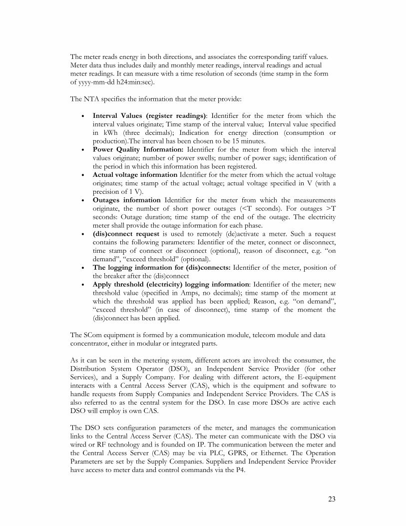
23
The meter reads energy in both directions, and associates the corresponding tariff values. Meter data thus includes daily and monthly meter readings, interval readings and actual meter readings. It can measure with a time resolution of seconds (time stamp in the form of yyyy-mm-dd h24:min:sec). The NTA specifies the information that the meter provide:
• Interval Values (register readings): Identifier for the meter from which the interval values originate; Time stamp of the interval value; Interval value specified in kWh (three decimals); Indication for energy direction (consumption or production).The interval has been chosen to be 15 minutes.
• Power Quality Information: Identifier for the meter from which the interval values originate; number of power swells; number of power sags; identification of the period in which this information has been registered.
• Actual voltage information Identifier for the meter from which the actual voltage originates; time stamp of the actual voltage; actual voltage specified in V (with a precision of 1 V).
• Outages information Identifier for the meter from which the measurements originate, the number of short power outages (<T seconds). For outages >T seconds: Outage duration; time stamp of the end of the outage. The electricity meter shall provide the outage information for each phase.
• (dis)connect request is used to remotely (de)activate a meter. Such a request contains the following parameters: Identifier of the meter, connect or disconnect, time stamp of connect or disconnect (optional), reason of disconnect, e.g. “on demand”, “exceed threshold” (optional).
• The logging information for (dis)connects: Identifier of the meter, position of the breaker after the (dis)connect
• Apply threshold (electricity) logging information: Identifier of the meter; new threshold value (specified in Amps, no decimals); time stamp of the moment at which the threshold was applied has been applied; Reason, e.g. “on demand”, “exceed threshold” (in case of disconnect), time stamp of the moment the (dis)connect has been applied.
The SCom equipment is formed by a communication module, telecom module and data concentrator, either in modular or integrated parts. As it can be seen in the metering system, different actors are involved: the consumer, the Distribution System Operator (DSO), an Independent Service Provider (for other Services), and a Supply Company. For dealing with different actors, the E-equipment interacts with a Central Access Server (CAS), which is the equipment and software to handle requests from Supply Companies and Independent Service Providers. The CAS is also referred to as the central system for the DSO. In case more DSOs are active each DSO will employ is own CAS. The DSO sets configuration parameters of the meter, and manages the communication links to the Central Access Server (CAS). The meter can communicate with the DSO via wired or RF technology and is founded on IP. The communication between the meter and the Central Access Server (CAS) may be via PLC, GPRS, or Ethernet. The Operation Parameters are set by the Supply Companies. Suppliers and Independent Service Provider have access to meter data and control commands via the P4.

24
As the CAS is a shared resource, the person or legal entity that controls it can only have access to the entitled functions. This makes us understand that identification, authorization, authentication, and encryption aspects are important. These aspects are responsibilities of the DSO. In summary, we can say that the Smart Meter provides information regarding energy, times, tariffs, and identity of infrastructure elements. It also manages control information to connect and disconnect equipment. The Smart Meter is also a device that allows the interaction of different infrastructures, and that allow the entrance of external service providers that may use the data generated and/or concentrated to develop additional services. An important element in the Smart Meter infrastructure is the Central Access Server, because it allows the interaction of the different actors requiring data. In this complex system, the legal arrangements of the data are important, and should be in agreement with the institutional design; for instance, allocation or responsibilities regarding ownership and management of data are of high relevance.
4.2.2. Other Enabling Technologies
There are other enabling technologies, including more demand-side resources10. However, we can make a differentiation on the nature of the support that they provide. There are technologies that directly support the physical and economic flow of electricity, while others support the information flow, which is an auxiliary flow. Examples of the first type of enabling technologies are advanced power electronics, energy storage and forecasting techniques. Advanced power electronics allows for a more flexible operation, and a higher quality of supply. They allow the integration of different types of interfaces in the network, and the variable-speed operation of electric generators and motors. Besides, it makes possible higher degree of control; for instance, in voltage regulation. Flexible Alternating Current Transmission Systems (FACTS) are part of power electronics advances, which enhances the controllability of AC transmission systems. Energy Storage is another important aspect of the technologies that can contribute for the TO-BE DN, and it represents a very important strategic value for energy networks in the future. Nevertheless, at the moment capacity/price ratios do not yet justify abundant application of electricity storage technologies. Different types of energy storage technologies exists, including (flow) batteries, flywheels, superconducting magnetic energy storage, compressed air energy storage, ultra-capacitors, etc (Bayod-Rújula). Finally, Forecasting Techniques make possible more effective management of renewable resources that have a variable nature; for instance, wind and solar energy.
10
According to Ackermann et al. Ackermann, T., G. Andersson, et al. (2001). "Distributed generation: A definition." Electric Power Systems Research 57(3): 195-204., demand-side resources are resources such as load management systems, which provide energy efficiency options (i.e., to reduce peak electricity demand), and are not only based on local generation within the electrical system on the customer’s side of the meter, but also on means that reduce overall demand. Examples of demand-side resources are smart meters, heat storage, load limiters, programmable thermostats, etc.

25
The previously described technologies, which are physical and economic facilitators, come with the need of an ICT infrastructure for its integration. For instance, the additional control that may be provided by advanced power electronics is useful, only if there is sufficient information to develop additional functionalities. Energy storage can be beneficial to the system only if its capabilities are used accordingly to production and demand needs. Finally, forecasts may improve the planning in the system only if they are communicated timely and to the correct actors. For this reason, Information and Communications Technologies are very important, even though they indirectly support the energy and monetary flow, by supporting the information flow. ICT create the means for more complicated transactions and interactions between elements in the system. Wired and wireless technologies provide means for more innovative applications. Clearly Power Line Communications (PLC) is broadly contemplated both for the internal communications of the active system, and for providing additional services, like internet access. In the field of software structures, agent-based technology provides an option to develop local intelligence and decentralized architectures. 4.3. AS-IS Situation: The Passive Distribution Network
This AS-IS situation is the third element to be analyzed11. The electricity infrastructure lived a period of relative stability before policy measures for sustainable energy and liberalisation were pursued. This period of stability favoured the evolution of the electricity industry as we conceived it for a long time: large, integrated utilities in charge of generation, transport and commercialising energy. That is, in the AS-IS situation, the electricity value chain was completely integrated into one utility, and the transmission and distribution networks had a coordinated operation with all the other segments in the value chain. Following the technical and economic approach (section 3.2) the subsections 4.3.1 and 4.3.2 describe the sub-systems of the AS-IS network. These physical and technical subsystems are intended to facilitate the physical and monetary flows in the value chain. As described in previous sections, an information flow appears as an auxiliary flow. The information in the AS-IS network is described in section 4.3.3
4.3.1. Physical Sub-System of the AS-IS Network
Until now, electricity networks are conceived as the infrastructure that moves electricity from the generation points to the consumers. Due to economics of scale electricity generation is performed habitually in large centralized plants. From these places, the generated electricity needs to be transferred in HV over long distances to HV substations, making use of high voltages and via overhead lines (as it results more economical and minimise transport losses); this is called electricity transmission. The transmission grid is web-like, and is densely connected to achieve redundancy for a high reliability. From the high voltage substations, electricity is transferred to main distribution substations. The DN at its interface with the transmission grid has an open web or loop structure. Here, transmission lines feed the main distribution sub-stations, which step down the voltage to MV levels. From these sub-stations, the electricity distribution has (or operates as) a radial structure in which further voltage conversions are done in secondary
11
Probably a more-appropriate name is AS-WAS situation. However, the AS-IS only corresponds to a reference situation to visualize the intended changes. For this reason, a useful baseline is the passive, integrated electricity distribution network.

26
substations and LV substations, until the voltages to be supplied to final consumers are reached. The specific voltages in the DN vary depending on each country (Gomez-Exposito 2009). Figure 8 is based on the one presented by (Gomez-Exposito 2009), and illustrates the previously described electricity networks.
Figure 8: The Electricity System (Gomez-Exposito 2009)
In the Netherlands, the transmission network is defined as comprising the lines of 110 kV or higher, while the distribution network comprises all the other voltages under this value. For this thesis, the definition of different voltage levels is presented in the next table: Transmission National high-voltage network: networks intended to transmit
electricity at a voltage of 220 kV or higher and that are operated as such, and also cross-border connections with a voltage of 500 kV or higher
Transmission High-voltage network: networks intended to transmit electricity at a voltage of 110 kV or higher, but lower than 220 kV and that are operated as such
Distribution Medium-voltage network: networks intended to transmit electricity at a voltage of 1 kV or higher, but lower than 110 kV and that are operated as such
Distribution Low-voltage network: networks intended to transmit electricity at a voltage lower than 1 kV and that are operated as such.
4.3.1.1. Passive Elements in the Distribution Network
27
In broad terms, electricity networks are constituted by conductors (cables) and other line equipment. When the conductors are installed in overhead lines, the system also includes supports and insulators. Also, the conductors can be vested in an underground construction, where protective coverings for the conductors, ducts and markers are also installed. The transmission of electricity is mostly carried out using overhead lines. This requires the construction of supports that may be towers, poles, or other, which have cross arms and pole pins to support and separate the conductors. Insulators are non-conductive elements that isolate the conductors form each other as well as from the pole or tower. Other smaller elements for refined technical functions like tie wires and connectors are also present. Mainly, distribution of electricity is made through underground construction, in which conductors are buried in the ground. This is more expensive and more difficult to maintain than conventional overhead lines, but improvements in construction practices have made it economically possible for urban areas. In addition to conductor elements and its associated infrastructure, line equipment is necessary to enable transmission and distribution of electricity. This line equipment comprises transformers, which perform the step down of voltages, and other elements like fuses, arresters, voltage regulators, capacitors, switches, and reclosers.
4.3.1.2. Automation Systems In the AS-IS network, the main objective is to facilitate a reliable supply of energy to the consumers. For this purpose, in addition to the passive elements, there is a need for automation systems for managing, controlling and protecting the network. Automation systems constitute the “intelligence” of the AS-IS electricity network, and the information to be handled is mainly intended for this system. This will be further explained the section 4.3.3, Information in the AS-IS Network, but before that, is important to understand the functionality and the physical structure of these systems. At this point, it is important to remark that automation systems constitute the present “intelligence12” of the AS-IS electricity network. By now, this system is primarily installed in the transmission network, reaching only the higher voltage parts of the distribution network. At the lower voltage consumer end very little intelligence is currently present; however, it is fair to state that the advent of decentralize generation is cascading down the intelligence towards the consumer ends. For example, the recent connection of CHP and wind energy in the MV, requires automation of the system at that level of the DN. Decentralized generation and other electric loads connected in the LV DN (for instance, the inclusion of micro-grids, and electric cars) will require further deployment of “intelligence” at this level in the DN. This phenomenon, the change in information requirements in the DN, is precisely the subject of this MSc thesis.
12
Intelligence in this context refers to the capacity of the network to perform informed decisions de Boo,
R. (2008). The Dutch Electricity Sector. Research Assignment. Delft, EWI, Delft University of
Technology. In this particular case of intelligence is interpreted as the functions performed by the
automation systems.

28
Functional Description of the Automation System
According to Strauss (Strauss 2003), the electricity system automation is formed by the following components: electrical protection, control, measurement, monitoring, and data communications. The next Figure 9 is based on the representation of this author of the functional structure of the electricity system automation.
Figure 9: The elements o fan automation system (Strauss 2003)
Strauss (2003), explains the functions of the automation systems as follows. The electrical protection objective is to look after the personnel and equipment, and to limit the damage in case of an electrical fault. The control component includes local and remote operation, and is related to switching operations, bay interlocking, and synchronizing checks. Local control refers to actions that a device can logically take by itself; remote control is closely related to the SCADA (Supervisory control and data acquisition) system functions. The measurement component consists on collecting electrical (voltage, currents, power factors, etc), analogue (transformer and motors temperatures), and disturbance recordings in order to make network studies. These measurements provide real-time information, that is used for the central control, and that is stored in a central database. The monitoring component consists of collecting information like sequence-of-event recordings, status and condition of the system including maintenance information, to assist in fault analysis and therefore improve the efficiency of the electricity system. Finally, the data communication component is the core of the automation system, as it provides the means for the other components to function, and to interoperate.
Physical Description of the Automation System
According to Strauss (Strauss 2003) a common basic structure of today’s automation system (installed in a previously unified electricity network comprising transmission and distribution) is composed by a SCADA system, a communications network, and an object division. This is represented in the Figure 10 below.
• The SCADA system consists on at least one master station, and is the central control of the automation system, as it receives information from the remote devices, processes it, and makes decisions;
• The communication network provides the channels to ensure that the information exchanged between different devices arrives in a timely, effectively and error-free way;
• The object division is the input/output part, and the local intelligence. It is localized in the substations, and therefore, provide remote access to it. We can say that the object division comprises two parts: 1) the process level, which is formed by current transformers, voltage transformers, different transducers, etc, and 2) the

29
bay level, which is the local intelligence formed by intelligent electronic devices (IEDs), microprocessor based relays, remote terminal units (RTUs), and programmable logic controllers (PLC).
Figure 10: Strauss Basic architecture of the electricity system automation
In general SCADA master stations are installed only in large generation or high-voltage transmission substations, while smaller distribution substations will only justify a shared SCADA master. In the latter case, only a SCADA interface is part of the substation control and automation system. This is exemplified in the next Figure 11:
Figure 11: Representation of the AS-IS Automation System
4.3.2. Economic Sub-System of the AS-IS Network
The AS-IS situation corresponds to an electricity system vertically integrated, where all the functions are performed by one utility. In this situation, transmission and distribution work jointly, and they do not need to facilitate competitive activities in the adjacent segments, as no market mechanisms are introduced in the system. With this, there is any tension

30
between regulated and competitive segments, and the approach is to remunerate the Distribution System Operator (DSO) is with cost of service or rate of return regulation, based on actual audited distribution costs (Cossent, Gomez et al. 2009). Following this reasoning, we can say that in the AS-IS situation, the electricity networks do not individually support any economic sub-system.
4.3.3. Information in the AS-IS Network
In the AS-IS (distribution) network only physical functions are performed, and the coordination between segments in the value chain is not necessary because all is operated as a single unit. In these conditions, the most critical functions13 are performed by the automation system, and the information flows important to recognize are the ones related to this system. From the functional description of the automation system, we can observe that the monitoring and measurement components are the sources of information; the control and electrical protection process this information and operate in consequence of it; the data-communications component provides the means for information flow. Indeed, the type of information from the monitoring, measurement, control and electrical protection, will dictate the necessary structure to deploy the data communications component. For instance, the communication links, the technology used, etc. depends on the type of information to be managed. In the case of the AS-IS network, protection of local elements requires real-time communication in case of a fault, and the response action also should be communicated as fast as possible; therefore, the adequate infrastructure to support this information is a dedicated link for signals transmission. In the AS-IS system, the rules and codes of this information, only depends on the needs imposed by the physical infrastructure. That is, the standards and codes for the automation systems are designed based on the needs of the physical sub-system. 4.4. TO-BE Situation: The Active Distribution Network
The TO-BE situation is the fourth element to be analyzed to construct an Information-Architecture. Environmental concerns, structural changes in the electricity system, and renewal of network assets are some of the motivations for devising a different electricity network. In response, several visions have been formulated about the possible futures; we take one of these visions to conceptualize the TO-BE DN14. The objective of this section is to explain several visions formulated around the future electricity networks. First, we explain the notion of a “smart grid” as a generalized notion existent for the whole sector. Then, we focus on the DN, and we describe three visions. At the end, we chose one of these visions to form the TO-BE situation for this thesis. This vision is the active network situation, and we explain more in depth the physical and economic elements included on it.
4.4.1. The Concept of a Smart Grid
13 The concept of a critical function is provided in the section 5.3.2 14 The TO-BE situation is only a possible situation. This description is not a forecast of the future, but a target visualization of the network that is useful to construct an information-architecture

31
It is a widespread vision for the electricity networks to become “smarter”. For instance, in Europe the approach to this idea is the development of the “SmartGrid” concept; in US the approach is named “GridWise” (Coll-Mayor, Paget et al. 2007). As a working definition to use in this thesis, we use the definition of a Smart Grid provided by the Advisory Council of the SmartGrid European Technology Platform (Advisory_Council 2008) as “an electricity network that can intelligently integrate the actions of all users connected to it- generators, consumers and those that do both- in order to efficiently deliver sustainable, economic and secure electricity supplies”. In this definition, still the notion of “intelligent” is not clarified. We use the idea of “intelligent” provided by de Boo(2008) as making informed decisions. The notion of “intelligence” (used indifferently from “smart” or “wise”) also comprises the inclusion of innovative products and services together with monitoring, control, communication, and self-healing technologies to facilitate the connection of all types of generators, to allow consumers to participate in the optimization of the operation of the system, to provide more information and a choice of supply for the customers, to reduce the environmental impact, and to enhance the reliability and security of supply levels (Advisory_Council 2008).
4.4.2. The Visions of a Smart Distribution Network
The additional integration of “intelligence” on the grid is especially desirable on the distribution segment, because it is there where less automation infrastructure is developed, and where more potential changes will take place. For instance, the Advisory Council for European Commission, in its Strategic Deployment Document for SmartGrids (Advisory_Council 2008)has considered six priorities; the only segment contemplated in all of them is the DN. Because of the important role of DN, three conceptual models of a “smart” future have been developed around it: Microgrids, Active Network Supported by ICT, and the Internet Model (European_Communities 1995-2009). The first model is the Microgrid. A microgrid is a small-scale power supply that is designed for a small community; for instance, a housing estate, isolated rural communities, universities, commercial areas, etc (Abu-Sharkh, Arnold et al. 2006). This concept assumes a cluster of electrical and thermal loads together with small scale sources of electrical power and heat (Lasseter 2002). The microgrid is responsible for serving its consumers, and it can possibly control non-critical loads. Besides, the connection between these locally constrained networks and the electrical power network is through a well defined and controlled interface. These characteristics make a microgrid to act as a well behaved load or generator (Abu-Sharkh, Arnold et al. 2006). The second model is the Active Network. Active Networks are envisaged as the possible evolution of current passive distribution networks into one using active management for its operation. “Active Management means real time control and management of Distributed Generation units and distribution network devices based on real time measurements of primary system parameters (voltage and current)” (Currie, Ault et al. 2004). Also McDonald (2008) explains that active network management contrasts with the straightforward connection of distributed generation, and instead aims to integrate it with higher control

32
and coordination for the entire power system operation. He also recognizes active management to make use of other distributed resources to relieve network constraints. The third model is the Internet Model. This model extends the concept of an active network to a global scale but distributes the control around the system. In this view, the energy could flow from suppliers to customers like data packets do in the Internet (Tsoukalas and Gao 2008). In this context, like in the internet, the flow of information uses the concept of distributed control where each node (element) acts autonomously under a global protocol. As an analogy, in the electricity system every supply point, consumer, and switching facility corresponds to a node in the network (European_Communities 1995-2009). We can see that the three previous models differ on their “spatial” and “time” scope. In terms of “spatial” scope, Microgrids are conceptualized for small areas independently form the transmission and DN; Active Networks are conceptualized as an evolution of nowadays distribution infrastructure; the Internet Model is a joint evolution of transmission and distribution networks. In terms of the “time” scope, Microgrids and Active Networks are visualized in a closer future than the Internet Model. In that sense, Active Networks and Microgrids might be complementary parts of a near future “smart grid”. On the other hand, the Internet Model is a more futuristic view that does not necessarily come from the evolution of the two previously mentioned models. The Advisory Council for the European Commission (Advisory_Council 2008) recognizes the deployment of Active Distribution Networks as a priority in their Strategic Plan for the Europe’s Electricity Networks of the Future in a timeline from 2010-2020.
4.4.3. The Active Network The “active” term appears in opposition to the traditional conceptualization of a passive network, in which the power flow is unidirectional from the HV to the LV. The “active” nature of the network also contrasts to the so-called “fit and forget” policy, that consists on using the former methods to operate the network irrespective if distributed resources are connected or not. There are some reasons that motivate an “active network”. The first reason is to react to the large penetration of DG. McDonald (2008) defends the relevance of active management methods in the integration of DG, saying that with them DNs can accommodate about three times more DG connections than equivalent networks without active management (In this case McDonald refers to DG connected in both MV and LV). In the section 4.1.1 we explained that some degree of active management is already present in the MV DN; but it is likely that this “intelligence” is spread closer to the end-user if small DG increases its presence in the networks. The second reason is related to investment in network assets. It would be likely that network elements need to be reinforced in order to accommodate higher and different electricity flows. If active management is functioning optimally, the required investments for upgrading the network may be reduced, because electricity could be administrated in a way that energy production is closer to the consumers. Moreover, local generation may support the local network at times of stress on the main grid.

33
The third reason is to allow for new functionalities that may make the demand side more participative (demand side management), and overall energy distribution more efficient causing energy savings. In addition to these three reasons, there are other less generic motivations for having an active network: the emergence of intelligent building services in both residential and commercial premises, and to anticipate on wide usage of electrical transportation vehicles (Advisory_Council 2008). Nonetheless, is out of the scope of this thesis to address these topics. For the purposes of this thesis, we will consider the concept of Active Network as the TO-BE situation of the DN. In the TO-BE DN, we can still recognize the three main flows in the value chain: physical, monetary and information flows. However, the information flow in the TO-BE DN acquires higher importance than in the AS-IS situation, given that both physical and economic sub-systems become more complex. In the next sections, we describe the physical sub-system, the economic sub-system, and the information flows as consequences of this new structure. Although in the common visions about the active network, the issue of unbundling is not related, in this thesis, the TO-BE situation includes this condition.
4.4.4. Physical Sub-system of the TO-BE DN
The European Communities website, McDonald, and Currie, Ault et al. (European_Communities 1995-2009; Currie, Ault et al. 2004; McDonald 2008) coincides on some desired characteristics for the DN.
• Different grid design: An Active Network requires novel grid designs; it would have increased interconnections, opposed to the current mostly linear or radial structure of the current DN. One important aspect to consider is the bi-directional nature of the active network design.
• More measurement, control and communication facilities: Different communication technologies might have to be included in order to fulfill different types of functions. The inclusion of sensor elements and communication links facilitates to monitor the state of the system, and must be in agreement with the communication technology used.
• More control and management of different elements on the network: Power flow management, voltage control, power quality management, load management, demand side management, and fault level control.
• Management of different interfaces: Different types of generators (synchronous, asynchronous, dc) will be connected in the DN; therefore, the management of their interfaces should be established. Note that all DG will have local interfaces that will allow adaptation to the AC 50/60 Hz nature of the DN.
• Higher protection mechanisms: Faster protection mechanisms and automatic reconfiguration is necessary to avoid high fault levels and domino effects (the self healing concept). These mechanisms require handling and processing real-time data and pervasive communication systems, and even to include network simulation for fast decisions (the real-time data gathering will require SCADA).
• Coordination and interaction over a wider area: The Active Network should be able to negotiate with neighboring areas for power exchange, it should be

34
coordinated between local control centers, and it should allow for higher interaction with the customer.
• Capability to cope with islanding operation. The Active Network should allow for the safe operation of the DN in an “isolated” mode (disconnected from the transmission grid)
The Advisory Council for the European Commission (Advisory_Council 2008) describes a typical active distribution networks’ structure, in which three layers can be recognized: 1) copper-based energy infrastructure, which is the actual energy grids that must be adapted 2) a communications layer, that should be implemented above the energy layer in order to facilitate overall connectivity of elements 3) a software layer that would add new functionalities and coordinated execution of operations. The Advisory council also provides a conceptualization of the infrastructure of an Active Network. This is represented in the figure above. In this figure, we can distinguish two new aspects regarding the information and communication systems, in general terms:
• The automation systems are extended to the edges of the DN, in order to provide support for the transient operational control. That is, a SCADA-type system is deployed towards the LV DN. This is represented in the left part of Figure 12, and it is represented in a more detailed way in the Figure 13
• New applications need an additional ICT infrastructure, and this depends on the speed required for the information flow. For instance governance systems can be added, and be IP-based. This is represented in the right part of Figure 12.
Figure 12: Structure of an Active Network. Modified from (Advisory_Council 2008)

35
Figure 13: Representation of the Automation System in the TO-BE DN. The elements are extended
towards the low voltage network
It is out of the scope of this research to analyze how the information is structured within the elements connected to the DN; for instance, a microgrid can be considered a load connected to the DN and we will not explain the IA within it. Besides, from the broad range of demand side resources, only the Smart Meter will be considered as being part of the active management system of this network. Demand-side management and self-healing mechanisms will not be included in our visualization of the active network, even though their importance is not neglected. It is suggested that these concepts are taken into account in further research.
4.4.5. Economic Sub-system of the TO-BE DN In the TO-BE DN not only the physical sub-system has to be adapted to the entrance of DG and to an unbundled environment, but also the economic sub-system needs to be adjusted. In the TO-BE situation, economic transactions are introduced for the overall functioning of the system and the institutional design in a liberalized market become more complex (see section 3.2). In this new situation, the role of DSO is to facilitate commercial activities of the segments linked to it: it needs to favor DG entrance in a way that is beneficial for the entire system and at the same time work under the institutional arrangements framed by the unbundled environment.

36
Still, the DN has characteristics of a natural monopoly, and therefore, the DSO should remain as a regulated entity. However, to act as a market facilitator, the DSO requires an adjustment of its business philosophy from a passive to an active one, in its business activities are expanded. Active management is the tool that the DSO may use to increment its business activities. For instance, several studies confirm that DG has capabilities to provide additional network services (two examples of are added in Appendix VI). The DSO may use these capabilities to improve the economic performance of its business. Technologies for small DG have a good potential to provide different services. Micro CHP in high penetrations is able to provide reserve services and network support. Solar PV also can contribute to provision of reserve, and to provide reactive power in the network (Degner, Schmid et al. 2006). Van Werven and Scheepers (2005) suggest that a DSO, in presence of DG, can develop active management to provide additional reliability, system information, local balancing, storage, and congestion management. These additional services would bring extra revenue streams necessary to sustain the DSO business15. The diagram developed by these authors representing the revenue and expenses stream in the DSO is in Appendix VII. In this change on the economic activities of the DSO, it is worthy to remark the significance of adequate regulation. Regulation has to incentivize the DSO to increase efficiency, to maintain a good quality of service, to innovate, and to favor competition providing a non-discriminatory network access and use. For this, regulation should contemplate a correct remuneration for the DSO, and to ensure a compatible business model that does not conflict with the other segments of the value chain. Particularly, the DSO should receive enough incentives to adopt active management in its operations. In our case, it is important that to avoid conflicts between DG and DSO. The goals determined for the DN (to allow non-discriminatory access) and its financial performance (having more expenses for the inclusion of DG) may contradict, and here, the institutional design is decisive to solve these conflicts. In conclusion, the adherence of economic activities produces a need of increasing the functions and services provided by the DSO. The role of regulation is fundamental for the correct inclusion of DG, and for the correct compensation of the DN activities. Institutional arrangements should be adequate to solve the conflict between the regulated nature of the DN and the competitive nature of the production segment DG.
4.4.6. Information in the TO-BE DN
Both DG and ownership unbundling bring more transactions into the system, and therefore, they call for more intelligence to manage the network. As a result, information becomes more important in the TO-BE situation than in the AS-IS situation. Differently form the case of the AS-IS DN, in addition to the technical functions to preserve the flow of electricity, the TO-BE DN needs also to support the economic
15 It is, however, questionable if the proposed business model by van Werven and Shceepers (2007) are in
opposition with the strong public utility characteristics of the networks in the Netherlands by Künneke, R.
and T. Fens (2007).

37
transactions brought with the inclusion of market mechanisms. The DN is a regulated entity but it needs to adequately cope with its adjacent competitive segments. For this reason, in addition to the traditionally technical functions performed in the AS-IS situation, the TO-BE DN adds some economic functions (or “economic-supporting” functions). An important characteristic in the TO-BE situation is that information should support a higher number of functions. A second characteristic in the TO-BE situation is that the inclusion of DG pushes for more intelligence at the customer end of the network. Automation systems, previously developed in the transmission network up to the main distribution substations, are likely to reach the low voltage network. The reason is not only to extend the protection mechanisms, but to control the elements connected to the network to operate in a more economic efficient way. Other source of data expected to be installed near the customer is the Smart Meter, which is clearly an important element in the development of an active network. This device is able to provide disaggregated information that can be processed to achieve an active management. A third characteristic is that the availability of data sources should agree with the presence of physical and monetary flows, in order to track them. In the AS-IS situation, the customer is out of the utility, and there is only need of data in an aggregated way. In the TO-BE situation, the customer becomes somehow part of the utility, and therefore, is imperative to keep track of specific production/consumption generated on it. This brings two consequences: the extension of data sources towards the customer16, and higher degree of detail17 in the data managed. The information in the TO-BE network is indeed the core part of this thesis. In the following chapter, this subject will be further developed. 4.5. Conclusions
What are the design requirements imposed by distributed generation for an IA of the electricity distribution networks? The design requirements for an IA are deducted under the assumption that the objective is to represent the information characteristics in a DN that appropriately accommodate DG. First of all, information should support both physical and economic flows generated by DG inclusion into the system. Landsbergen (2009) explains that up to approximately 75% of small DG penetration, there isn’t any major technical impact in the network. So, in principle, for the physical integration, any relevant change in the automation system infrastructure needs to be done. However, in the economic integration, it is desirable that DG participates in different markets, and favors a more efficient electricity use for the overall system. For these activities, information systems do require to be developed. A second requirement for an IA is that it should allow for a flexible and expandable design. DG presents economies of geographic concentration, which makes attractive more
16
This is clearly exemplified by the Smart Meter concept, where the production of valuable data is situated in the customer end of the network. 17 For instance, before, the measurement of energy could be done in a monthly basis, and for some
functions, only regional aggregated indicators were enough. In the TO-BE situation, customer id,
location, time, are important information.

38
installation of DG in the same area, but the process may be gradual. In this sense, the IA should consider that different levels of DG have different effects; in broad terms, the higher the levels of DG, the higher the complexity of the information systems that needs to be integrated. A third requirement that the IA should consider, especially for the case of a large amount of DG in one area, is the extension of “intelligence” towards the edge of the network, and, the resultant inclusion of new elements at this level. This “intelligence” comprises the development of all the areas of the nowadays automation system: control, protection, monitoring, measurement and communications.
• Protection and control: To prevent network stability and unintentional islanding (in case of large amounts of DG)
• Control: For providing ancillary services and participate in balancing markets. • Measurement: For having specific information of the physical state of the DG
installation (i.e. with transducers), for having detailed information of energy produced/consumed at different times (i.e. with Smart Meter), and for understanding the interaction with other infrastructures (i.e. with a Smart Meter).
• Monitoring and control: to concentrate and interpret the measurements performed, and to provide governance to the system.
• Communications: to establish adequate links to support different types of transactions; for instance, real-time communications technology for protection functions and near-real time for economic functions.
A fourth requirement for the IA is that it should contemplate the already existent infrastructure. The (new) infrastructure supporting economic transactions and the (previous) one supporting physical transactions should have a coherent interconnection: the information effects that economic transactions have on the physical sub-system should be clearly depicted. Finally, it is important to re-state the importance of policies in the development of large DG. The IA needs to be designed not only based on physical and economic functionalities, but also on the institutional agreements around DG. For instance, as policies and regulation are determinant for the behavior of the DSO, the information exchange between actors from legal institutions is important to be considered in the architecture. What are the design requirements imposed by ownership unbundling for an IA of the electricity distribution network? Unbundling imposes challenges for the operation of a previously unified entity. The coordination achieved in the AS-IS situation by a common management, is achieved by ICT systems in the TO-BE situation. For instance, in the expected business model of an active DSO, more information need to be exchanged between DSO-DG Operator, DSO-TSO, DSO-Retailer, and DSO-Customer. Therefore, the first requirement for an IA is to be comprehensive; that is, it should cover all the relevant segments to which the DN has physical or economic connections. Besides, to meet proper coordination, ICT systems should be compatible among the relevant actors. For instance, metering systems should provide information in a format that different actors can process and interpret. In other words, interoperability of the systems deployed by the DSO with the information sources provided by DG, customers, retailers and TSO should be guaranteed.

39
Moreover, in an unbundled environment, each actor has an independent planning, and information can help in the compatibility of this planning. For this, information should be consistent for all the actors. On the other hand, unbundling is considered beneficial for the electricity sector in the Netherlands, because it favors the proper operation of competitive segments under a “commodity model” and the operation of networks under a “public utility model” (Künneke and Fens 2007). Even with this separation, it is expected that the DSO needs to incorporate more functions to cope with the competitive environment that surrounds it. To be able to develop more functionalities, the DSO needs more detailed information regarding energy consumption and production, which by now, is only available in an aggregated level in terms of time and location. More detailed information of the end part of the network is needed. Ownership unbundling also implies that in addition to the required information for its own functions, each segment in the value chain will need to share information with other actors to have adequate visibility of the overall system. In our specific case, there should be a proper differentiation between the information used internally by DSO, and the one that may be shared with other actors, because the DSO may handle sensitive information for the market functioning. For instance, rules for access, and use of metering information should be designed in a way that do not interfere with the proper market functioning. Lastly, unbundling it is believed to provide economic-efficiency to the system. However, if the installation of the ICT systems necessary to operate in an unbundled environment is very expensive, the benefits of unbundling may be covered. The IA should be design in a way that facilitates a cost-effective deployment of the ICT systems. In general, simplicity is a consequent desirable characteristic.

40
Chapter 5. Design of the IA for the Distribution Network
This chapter is the second part of the analysis phase of this thesis. In chapter 4, we explained four elements needed to understand the problem under study: the context (distributed generation DG and ownership unbundling), the enabling technologies (Smart meter), the AS-IS distribution network (DN), and the TO-BE DN. This chapter uses the elements developed in the previous chapter to give a concrete example on how IA may be depicted. Thus, the main question to solve in this chapter is “how can an IA for the electricity distribution network, which fulfills the design requirements imposed by distributed generation and ownership unbundling, be designed?” To solve this question, we employ TOGAF/ADM development cycle introduced in Chapter 2. Accordingly, this chapter is divided in 4 sections, which correspond to the first four phases of the ADM development cycle. In section 5.1, we describe a preliminary phase, which aims to provide a description on how the architectural work for the DN would be done. In section 5.2, we address phase A “the Architecture Vision”, which is intended to define the scope, clarify the vision, and to identify the stakeholders. In section 5.3, phase B “Business Architecture”, we give insights on the baseline and the target “business” organization, functions, and information. Finally, in section 5.4, we describe phase C “Information Systems Architecture”, where we define the necessary data, and data sources to support business functions. 5.1. Preliminary Phase
The preliminary phase of the TOGAF/ADM is intended to prepare the enterprise for a successful “architectural work18”, which is the design of an information-architecture. The main objective of this phase is to delineate how this design work will be done. Approach of the Enterprise Architecture The concept of Enterprise Architecture, as used by TOGAF in the ADM cycle, refers to a work made for the internal use of an enterprise in order to guide the development of their ICT assets. Therefore, an important part of the Enterprise-Architecture construction is devoted to connect the architectural work to the internal organization of the enterprise, in order to ensure adequate support. This approach is different from the one suggested in this thesis, in mainly in two aspects: 1) The TO-BE electricity utility is not one enterprise, but a collection of “new”
organizations that manage the unbundled functional parts of the electricity system. In other words, the electricity system is not an enterprise, but a complete sector.
2) The design of the “Information Architecture” intends to contribute to the development of a whole energy system (for instance, to the national energy system of the Netherlands), and not necessarily to the internal deployment plans of a distribution company.
18 In the wording of TOGAF, the architectural work is the project which objective is the design of an
enterprise-architecture. In this case, the architectural work is the design of an IA for the electricity
distribution system (see the definition and purpose of the architectural work).

41
These differences cause discrepancies on the application of ADM development cycle, and on the scope of the architectural work. For instance, internal specific issues like resources, approvals, sponsoring, are neglected in the following phases. Definition and purpose of the architectural work The architectural work consists on building an IA for an electricity distribution network (DN). Specific assumptions used for this construction are based the case of the electricity system in the Netherlands. The IA to be constructed is a high level representation of the information handled by the electricity system, specifically regarding the distribution function, which is performed by the Distribution System Operator (DSO). The IA purpose is to represent the information needed for the adoption of active management by the DSO. This information is the one required to adjust DSO’s activities to the ongoing process of liberalization and integration of distributed generation in the low voltage network. Therefore, these two events determine the requirements for the architecture. This IA may be useful for policy makers, regulators, and distribution companies to conceptualize the information changes due to institutional and technological transformations in the sector. 5.2. Phase A: The Architecture Vision for the Distribution Network
This is the fist phase of the ADM cycle, and the main objective is to define a clear vision for the architectural work to fulfill the purposes defined in the preliminary phase. In our case, the architecture vision must mention that the scope is to develop only up to the IA phase. Other elements of the architectural vision can be deducted from section 2.3. Important elements to build an architecture vision are: The business goals In the case of the electricity industry, the goals are established in the European directives as to achieve sustainable, secure and competitive energy (Comission_for_the_European_Communities 2007). Policy makers pursue these goals by designing the structure of the institutions and rules for the industry. In the case of the DSO, business goals are imposed directly by policy makers, and preserved by regulators, as the distribution activity follows the “public utility model”. Therefore, the most important goals for the DSO include guaranteeing security of supply, to maintain a good quality of service, to innovate, and to favor competition by providing a non-discriminatory network access and use. The strategic drivers It is assumed that to achieve the energy policy goals established, ownership unbundling and large entrance of distributed generation are desirable events, and drivers for change of the overall system. The main strategic driver of change for the DSO is the need to cope with these two events. The principles These are “general rules and guidelines that support the way in which an organization sets about fulfilling its mission”(TOGAF 2009). In the case of the electricity networks, the

42
general rules and guidelines are dictated by the national regulation; therefore, legal institutions establish how the operation of the DN should be. Stakeholders: There are the “entities” with some interest in the development of an IA for the TO-BE DN. In the strategic development plan for the smart grids (Advisory_Council 2008), for instance, the stakeholders are defined as the “prime movers who must make happen the deployment of active networks”. They are the end users and communities becoming producers and service providers, DSOs and their associations, research institutions and universities, industry in general (with emphasis on power systems components industry, which design the enabling technologies for making the active network feasible). 5.3. Phase B: The Business Architecture of the Distribution Network
The construction of a Business Architecture is the second phase of the ADM cycle. This phase consists on describing the DSO “business”, which is embedded on the electricity utility. The business architecture includes baseline (AS-IS) and target (TO-BE) organizational, functional, process, information, and geographic aspects of the electricity system, with focus on the distribution function. The description provided in Chapter 3 (Overview of the electricity system) and in sections 4.3 (AS-IS situation) and 4.4 (TO-BE situation) are useful to define the business architecture.
In the next paragraphs, we present the entities and the functions in the DN. They form the basic elements for the business description.
5.3.1. Entities that shape the electricity system
The “entities” are high-level components of the electricity system. To define an entity, it is useful the functional approach taken in the electricity value chain representation. We can define an entity as an actor or group of actors performing a similar function in the electricity industry. In section 4.3 we described the AS-IS situation of the DN, in which the whole system was unified, and its main task was facilitating the physical flow of electricity. In this situation the electricity utility does not integrates consumption on its operations; the customers are receivers of the services provided by the utility. From this description we can depict the AS-IS situation as formed by two entities: the vertically integrated utility, and the consumers. This is illustrated in the Figure 14 below. Function Production, Trade, Transmission, Distribution, Metering, Sales Consumption Entity
Customer
Figure 14: Entities of the system in the AS-IS situation
In the TO-BE situation, the effects of ownership unbundling and DG appear. As described in section 4.4 these events increase the complexity of the system, and maintaining economic flows acquires higher importance. From this description, we can deduct that the relevant “entities” are the ones composing the electricity value chain: large producers,

43
traders, TSO, DSO, metering service entities, retail companies, and consumers, plus the DG Operator19. Clearly, the main entity is the DSO, which manages and operates the DN. In the Electricity Directive (2003/54/EC), a distribution system operator is defined as: “(…) a natural or legal person responsible for operating, ensuring the maintenance of and, if necessary, developing the distribution system in a given area and, where applicable, its inter-connections with other systems and for ensuring the long term ability of the
system to meet reasonable demands for the distribution of electricity”(van Werven and Scheepers 2005). In the next figure (Figure 15), we depict the relevant entities: Function Production Trade Transmission Distribution Metering Sales Consumption Entity
Consumers
Figure 15: Entities in the system in the TO-BE situation
In contrast to the AS-IS situation, in the TO-BE situation the customer is more participative in the operations of the system. We could still name a separate entity “customer”, but, in this case, the customer performs both consumption and production of electricity. To agree with the functional approach taken to define entities, we divide the customer in two: a “consumer” and a “DG Operator”20. This fact makes the last entity to be different from the others, this is the reason of representing with a different (a rounded square) figure these entities in our illustration. From the previous definition of entity, we can see that as all entities are physically linked, the boundaries require to be defined by institutional arrangements. These arrangements should also determine the interaction between entities. By now, all our analysis contemplates only market actors. In addition to the entities associated to the value chain functions, in section 4.5, we highlighted the role of the legal institutions (i.e. regulator) in the TO-BE situation. Therefore, we should consider entities from this institution in our IA construction. In addition to the regulator, Fens (Fens 2009) recognizes the government, policy makers, regulator, and an energy data service entity as relevant entities in his depiction of the IA for the whole sector. These four entities are also relevant for the case of the DN.
• Government: Is the authority of the country. In general terms it has the power to make and enforce the law.
• Policy makers: Design the policies concerning to energy to be followed within the country.
19
DG Operator controls and aggregates the energy produced by various distributed generators. Strictly,
the operator does not generates electricity, but for simplicity, we can depict is a producer of the
aggregated energy generated by many customers. 20 As the energy produced by one consumer is very small, it is useful to have a DG Operator, who can manage and make decisions based on information at aggregated level (as suggested by van Werven and Shceepers van Werven, M. J. N. and M. J. J. Scheepers (2005). "The changing role of distribution system operators in liberalised and decentralising electricity markets." Proceedings 2005 International Conference on Future Power Systems..

44
• Regulator: Is the entity that monitors the performance of the industry • Energy data service: Is a functional entity in charge of administrating the
data/information. This can be integrated with other functional entities in one company; for instance, distribution and energy data service can be performed by the DSO.
5.3.2. Functions in the Distribution Network
To describe the business of electricity distribution, we have to recognize its main functions. Of special importance is to recognize the functions that are critical for safeguarding its technical performance, in order to preserve them even in times of change. This technical performance is expected to include reliability of the service (availability of energy for al customers connected at every time), safety (that does not put in danger the users and non-users of the electricity infrastructure), and security of supply (ability of sustaining the activities in the foreseeable future) (Kunneke, Groenewegen et al. 2009). Künneke and Groenewegen (2009) mention two important criteria to define the criticality of the functions:
• The technical scope of control. If a function is unique in the system, it is essential for the overall functioning of the system, and any other element or mechanism cannot replace its task, then, it can be considered as critical;
• The strength of time constraints involved. The shorter and more specific the times that a function requires to be activated, the more critical the function is.
Künneke en Groenewegen (2009) say that “technology imposes critical functions and that the benign neglect of this issue in reforms of infrastructures is reflected in misalignments of modes of organization with the requirements of the critical technical functions”. This clearly explains the importance of recognizing the critical technical functions in the DN, as we are foreseeing that they will suffer important transformations in the coming years. Besides, the institutional arrangements should be aligned and support this critical functions. Künneke and Finger (2007), identify the critical technical functions for the overall electricity system: capacity management (divided in operational, tactical and strategic), interconnection management, and interoperability management. The overview of their analysis is presented in the Appendix VIII From the description made in Chapter 4, we can conclude that in the TO-BE situation, more functions are required by the DN. The main difference comes from the inclusion of economic transactions supported by the DN (described in 4.4.5). The desirability of economic-supporting functions is reflected on an interest to increase physical infrastructure and to add more technical functions to the operation of the DSO. For instance, one function to be performed in the TO-BE DN is to incorporate control systems21. By comparing the physical sub-system in the AS-IS network and in the TO-BE network, we can see that an expected change is the extension of automation systems towards the end consumer. More control is not required due to the technical impact of
21 To incorporate control systems is the first additional function listed in the table. We use this function to exemplify how the information in the previous chapter is used to deduct the functionalities in the TO-BE situation.

45
connecting small DG (as it was explained in section 4.1.1), but is motivated by the economic-desirability of additional services provided by DG (4.4.5), and by the DG economics of geographic concentration (4.1.1). Doing a similar analysis, and based on the critical technical functions for the system defined by Künneke and Finger (2007), we developed the next table, which makes an inventory of the functions in the AS-IS and in the TO-BE situation. In this table, criticality is mainly determined by the strength of time constraints.
Function Description Critical
Provide Electric Protection
To install overcurrent protection, earth fault protection, leakage protection differential protection, systems in the low voltage distribution network.
YES
Perform Network Studies Analysis of the normal and emergency operating conditions for quality of supply reviews. These studies include: Load flow studies to optimize the distribution network design, calculate correct fault levels to determine relay trigger settings, stability studies for the system.
NO
Execute Corrective Maintenance
Faster reconfiguration and activities to repair an outage.
YES
Execute Preventive and Predictive Maintenance
Applied to network equipment to reduce the frequency of failures.
YES
Grid development and planning
Design new connections or enlargement of the existing ones consistent with existing demand, estimation of future demand, residential and industrial developments, environmental impacts, efficiency plans, generation facilities installed and design of the higher voltages grid
YES
Maintain and operate the physical interconnection with the TSO
Maintain adequate interconnection with the transmission network, so the service is reliable.
YES, as soon as DG does not account for the overall main generation means.
Develop Grid Codes for connecting users
Suggest the technical requirements to develop grid connection codes
YES
Metering at substations Metering of interconnection points for flow control.
NO
Calculation of Use of System Charges for users
Calculation of energy consumed from the grid
YES
AS-IS Distribution Network
Calculation of Connection Charges for users
Calculation of the connection costs for users NO
Incorporate control systems
Integrate voltage and frequency regulation in the distribution network
Only with very large entrance of DG
Provide local disturbance response (Balancing)
To match demand and supply energy locally, so the need for energy transportation is
4.1.1reduced
Only with very large entrance of DG
TO-BE Distribution Network
Provide Reserve Services Develop the necessary infrastructure to allow Only with

46
for TSO DG (mCHP) providing reserve services for the TSO
very large entrance of DG
Provide ancillary services (locally or to the TSO)
Develop the infrastructure so DG can provide compensation for power losses, frequency control, voltage support, reactive power, black start.
Only with very large entrance of DG
Provide system information services
Provide information about the system to DG Operators and suppliers that is valuable to improve their operations (i.e. flows in the network, demand, etc)
NO
Calculation of Use of System Charges for DG
Calculation of energy injected in the grid NO
Calculation of Connection Charges for DG
Calculation of connection and reinforcements needed
NO
Additional Reliability Providing extra reliability to customers with special needs; for instance, companies in ICT sector
NO
Planning for new DG Participate in the regulation for Distributed Generation installation, by communicating the location and characteristics for these generators that result optimal for the system, especially for reducing necessary investments on the grid.
NO
Maintain interconnection within the DSO
Design and maintain adequate interconnection within the distribution network, so the DG can import energy into the grid, and this energy can be consumed locally or exported to the transmission network. Also to develop adequate connection/disconnection mechanisms in case of intentional islanding operation
YES, as soon as DG does not account for the overall main generation means.
Administrate ICT systems for communicating with different actors
Administrate the dedicated communication networks with retailers, consumers, TSO, metering companies, etc.
YES
Develop Grid Codes for Distributed Generation Connected to the low voltage network
Grid codes specifying type, capacity and general characteristics of the DG connected. Also specify technical requirements for providing local ancillary services; for instance, automatic voltage regulator, resynchronization facilities, communication facilities, etc.
Only with very large entrance of DG
Administrate access to information systems
Access of detailed information regarding energy flows, DG production and consumption
NO
Metering load Monitoring data regarding consumption NO Metering production of DG
Monitoring data regarding DG production NO
Figure 16: Functions of the Distribution Network in the AS-IS and in the TO-BE situation
5.4. Phase C: The Information Systems Architecture
The third phase in ADM cycle is Phase C, “Information Systems Architecture”. This phase is divided in two: Information-Architecture, and Applications-Architecture. These architectures analyze functions requiring the support of ICT systems. The main objective this thesis is to explain the information-architecture; however, some general ideas will be added to contribute to the Applications Architecture.
47
5.4.1. Information Architecture
The objective of the IA is to “define major types and sources of data necessary to support the business”(TOGAF 2009). For this, section 4.2 (enabling technologies), and the elements and functions defined in section 5.3 (phase B, business architecture) are used.
5.4.1.1. Principles In the phase A “Architecture Vision”, some general principles governing the DSO activities are clarified. For the Information-Architecture, these specific principles should “provide guidance on the use and deployment of all ICT resources and assets across the enterprise”. Here, requirements imposed by DG and ownership unbundling can be applied. Restating some of the conclusions drawn in the last chapter, we can say that the Information-Architecture, to cope with DG, should be flexible, expandable, should provide a connection between physical and economic transactions to conciliate some undesirable discrepancies. In an unbundled environment, the design should be comprehensive for the relevant actors, should facilitate interoperability, and should promote information consistency. It should give more detailed information for the DSO to understand the behavior of production and consumption, should differentiate the information for internal use and the one adequate to be released to market actors, and should favor a cost-effective implementation.
5.4.1.2. Relevant Entities for the Distribution Function The next elements are the ones to which the DSO exchanges information:
• TSO: Manages the transmission network and operates the system for proper match between generation and load. DN and transmission networks are physically connected, and therefore is imperative their coordination. In the TO-BE situation, they need communication for local balancing, ancillary services, and use-of-system charges functions.
• Consumer: It is physically connected to the DN, and its functions are to consume electricity from the system, and from its own production of energy. The consumer interacts with the DG Operator, the retailer, with other service providers, and with the government (Fens 2009).
• DG Operator: We consider DG as the one physically connected to the LV DN; therefore, in the TO-BE situation, each consumer is also a producer of energy. These DGs are aggregated and coordinated by an additional actor, the DG Operator, because in this scheme they can provide different services like exporting electricity back to the grid, and participating in a market under a VPP scheme. There are different possibilities for vertical integration between this DG Operator and other entities, but for the purpose of illustrating information flows, we consider DG Operator as a separate entity that only produces energy.
• Retailer: Is the entity in charge of buying energy in the wholesale market and selling it to the customers. It can also provide additional services, and can be integrated with other functional entities.
• Metering Services Entity: Metering consists of measuring energy at certain points in the system. Depending on the location of these points, metering generates data that is owned by different users: In-feed meters are located at production sites, and

48
can be assigned to producers; interconnection-meters are located in the DN for energy flow control, and generate data for the DSO; usage meters are located at the end customer site, and the data is owned by retail units. In the DG scheme at LV level, the Smart-Meter can be considered as both in-feed meter and usage meter.
• Regulator: It is an entity form the legal institution and therefore a functional definition within the physical infrastructure is not possible. We can simplify the more elaborated nature of this entity by saying that its function is to oversee the performance of the other entities in the system.
5.4.1.3. Main Data Flows
In the electricity system, the information flow is a supporting flow for the physical (electricity) and economic (monetary) flows between functional segments. For this reason, information flows, in broader terms, represents the other main flows, and the entities associated in the exchange of electricity and/or money. For instance, information to be exchange includes: prices, power flows, capacity restrictions, dispatch instructions, demand forecast, load forecasts, intermittent generation forecast, contracted energy, contracted ancillary services, user identification data, connection identification data, etc. As we can see, each of these types of information can be categorized as measurements of energy, economic information, or entity-related information. The corresponding information sources are metering systems, forecasts studies (i.e. weather forecasts), network studies, costs from superior grid, grid utilization costs; laws (i.e. feed-in law, subsidies), and registries (i.e. users registries, connection registries, meter registries). It is interesting to mention again here that another difference between the AS-IS and the TO-BE situation is the level of detail of the data. In the TO-BE situation, the Smart Meter allows for more detailed information at customer level. This information was obtained only at aggregated level in the AS-IS situation. In the section 4.3.5, the exact information that can be obtained from the Smart Meter is provided.
5.4.1.4. Changes in the Information to perform distribution functions As a result of the technical and institutional changes, the IA between the AS-IS and the TO-BE DN is different. Here, we illustrate these differences with one example: the information flow to perform the function of “calculation of use-of-system chargers for users. This example 1) only illustrates the physical flow and the information flow; 2) only takes into account the flows that are relevant for the DSO; 3) the “building blocks” are the entities defined in section 5.3.1 In the next figures (Figure 17 and Figure 18), the physical flows are represented with yellow arrows, while the information flows are represented with orange arrows. The direction of the arrow represents the direction in which the information flows. The numbering is used to explain the different flows, but these flows are not necessarily following that temporal sequence; for instance, some flows may happen simultaneously. Information in the AS-IS situation In the AS-IS situation the overall cost to provide energy was charged to the customers in a cost-of-service scheme. Here, there was no need to make a differentiation between energy and transport costs for the customer. The energy was delivered to the customer (1), the

49
measurement of the energy consumed was received by the company (2), and the company informed the customer the charge for the use of the energy system and energy consumption (3). This can be visualized in Figure 17:
Figure 17: Information Exchange in the AS-IS situation (energy billing)
Information in the TO-BE situation In the TO-BE situation, the electricity system is under the condition of presence of ownership unbundling and DG. This is represented in the Figure 18 below.
Figure 18 Information exchange in the TO-BE situation (Use-of-system charges)
In this diagram we can observe that the metering services provide information about energy flow from/to transmission network to the DSO (1a), information about energy flow to the customers to the Retailer (1b), and information about energy injected to the DN to the DG Operator (1c). It is assumed that DSO has also access to 1b and 1c, information provided by smart metering at customer sites, and therefore, they can calculate the energy consumed from the grid, and the energy generated to the grid. As a result, 1b and 1c are useful to calculate the use-of-system charges which are different depending of the direction of the energy flow. The use-of-system information is passed to the retailer (2), which considers this for the overall billing for the customer (3). Besides, from 1a the use-of-system charges regarding transmission costs can be calculated. This information should be shared with the TSO (4). Finally, in all this process for the final billing calculation, the regulator defines the tariffs to be paid to the DSOs, based on the information of use-of system and other parameters like quality of service to cover the expenses of the services provided by DSO (5). Changes in the information From the previous exercise, we can deduct the main information differences between the AS-IS and the TO-BE situation of the DN. The first obvious difference is the presence of more information and the interaction of independent entities. Clearly, information in the TO-BE situation is more critical to perform a function.
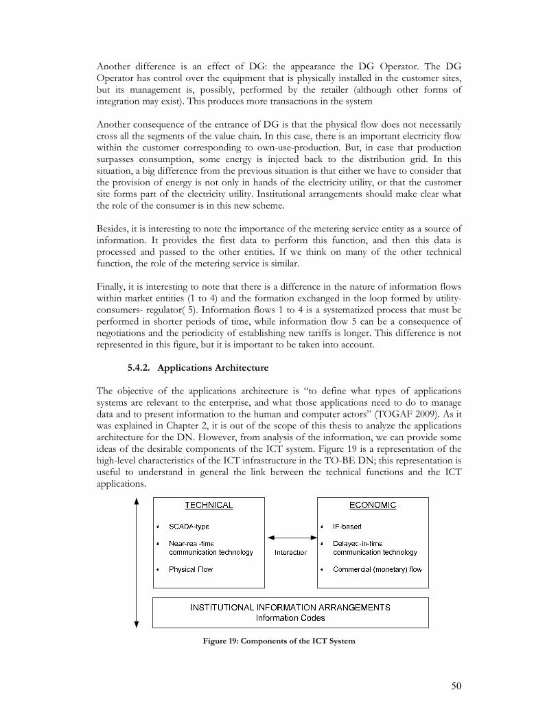
50
Another difference is an effect of DG: the appearance the DG Operator. The DG Operator has control over the equipment that is physically installed in the customer sites, but its management is, possibly, performed by the retailer (although other forms of integration may exist). This produces more transactions in the system Another consequence of the entrance of DG is that the physical flow does not necessarily cross all the segments of the value chain. In this case, there is an important electricity flow within the customer corresponding to own-use-production. But, in case that production surpasses consumption, some energy is injected back to the distribution grid. In this situation, a big difference from the previous situation is that either we have to consider that the provision of energy is not only in hands of the electricity utility, or that the customer site forms part of the electricity utility. Institutional arrangements should make clear what the role of the consumer is in this new scheme. Besides, it is interesting to note the importance of the metering service entity as a source of information. It provides the first data to perform this function, and then this data is processed and passed to the other entities. If we think on many of the other technical function, the role of the metering service is similar. Finally, it is interesting to note that there is a difference in the nature of information flows within market entities (1 to 4) and the formation exchanged in the loop formed by utility-consumers- regulator( 5). Information flows 1 to 4 is a systematized process that must be performed in shorter periods of time, while information flow 5 can be a consequence of negotiations and the periodicity of establishing new tariffs is longer. This difference is not represented in this figure, but it is important to be taken into account.
5.4.2. Applications Architecture The objective of the applications architecture is “to define what types of applications systems are relevant to the enterprise, and what those applications need to do to manage data and to present information to the human and computer actors” (TOGAF 2009). As it was explained in Chapter 2, it is out of the scope of this thesis to analyze the applications architecture for the DN. However, from analysis of the information, we can provide some ideas of the desirable components of the ICT system. Figure 19 is a representation of the high-level characteristics of the ICT infrastructure in the TO-BE DN; this representation is useful to understand in general the link between the technical functions and the ICT applications.
Figure 19: Components of the ICT System

51
In the upper part of the figure we can observe two main components: the “technical” and the “economic” components. In the electricity networks, physical and economic flows are present and they are related; in the same way, the functions for preserving a correct physical and economic flow in the DN are connected. For instance, if the payment of network costs is not carried out, provision of energy is unfeasible. In this sense, there should be a unique supporting information system that takes into account both types of flows in the system, and the interaction between technical and economic functions. On the other hand, if criticality is measured in terms of time constraints, functions with an economic-base are less critical. This produces an important qualitative difference between the type of information supporting physical flow and the one supporting economic flow: the information supporting economic (non-critical) functions allows for slight time delay. From this logic, we can depict the information needs in two categories:
• The first category is the information supporting critical functions, which needed real-time communication of lower level functions. An extension of the SCADA system deployed at transmission level towards the end-users is an option for this category.
• The second category is the information supporting non-critical functions, where
the communication allows for certain delays, but that is intended for developing “higher level” applications. For this information infrastructure, a key element is the Smart Metering.
As an addition to the representation of the technical and economic supporting applications, we must take into account the role of institutional arrangements in the design of information systems. This is represented in the lower part of the figure. With the inclusion of an information layer (and their increasing relevance in the functioning of the entire system) specific institutional arrangements for information should be developed in order to preserve the institutional design of the electricity system. Information codes that regulate the exchange of information, codes defining data formats, access rules, and ownership of information should be designed to favor the transformation of the DN, and to keep coherence with other market and social institutions. For instance, information codes must be aligned –and fame- information systems to reinforce only the desired effects of unbundling (i.e. diminish the transaction costs and to favor market functioning). In conclusion, it is very important that the design of technical and economic supporting infrastructure and the design of institutional information arrangements are aligned. 5.5. Conclusions
How can an IA for the electricity distribution network, which fulfills the design requirements imposed by distributed generation and ownership unbundling, be designed? First of all, it is useful to support the design of an IA with an architecture framework. In this thesis, we used TOGAF/ADM development cycle as a supporting tool. However, the concept of Information-Architecture, as employed on this methodology, can not be fully adapted to the case of the electricity system, because of the difference between the enterprises’ scope, taken in architecture frameworks, and the whole sector’s scope, needed for the case of electricity distribution.

52
Based on TOGAF/ADM recommendations, the first step to develop and IA for the DN is to scope and define the architectural work. This favors in an earlier stage consensus between relevant actors (DSO, TSO, Metering Services Companies, Retailers, DG operators, Regulator, etc.) on the development of an Information-Architecture. The second step is to formulate an architectural vision presenting a clear description of the IA to be developed. In this vision, goals, general principles, and assumptions have to be specified. The architectural vision can be confronted to check if there is agreement among different actors’ vision about the future system. One initial drawback in formulating a vision for the electricity sector is that regulated and competitive segments have inherently different goals. The architectural vision should be formed in a way that discrepancies between segments are solved. The third step is to build a Business-Architecture, where abstract ideas from the previous phases are settled down into a concise depiction of elements and functions relevant for the operation of the DN. Entities and functions become the “building blocks” for the Information-Architecture. The last step is to develop an Information-Architecture. This architecture is a concrete representation of the type of information, information flows, and information sources that the DN needs to support its business functions. The principles that must be followed to develop the IA are based on the specific requirements imposed by DG and ownership unbundling (the context). Based on a simple exercise of the depiction of information in the TO-BE DN, we can say that information flows are more critical, they support higher number of functions, provide higher degree of detail, and that information sources are closer to the customers. Additionally, some ideas for the construction of an Applications–Architecture were included. The TO-BE information infrastructure should include information supporting technical transactions, and information supporting economic transactions. These two parts of the infrastructure are different because the former requires a real-time communication technology, while the later allows for a “delayed in time”22 communications technology. Evidently, these two parts of should be interconnected reflecting the effects that economic transactions have on physical transactions. These two components should be aligned with institutional arrangements created for information.
22 These are technologies where the information suffers latency in the communications mean.

53
Chapter 6. Reflection
In this chapter, we present an assessment of the research performed for this thesis. This reflection was performed after almost all the analysis was completed, and is intended to provide insights on the overall result achieved. The main objective of making a reflection is to deduct what can be learned from the process of making the research itself, and this knowledge can contribute for a better continuation on this topic. For this purpose, this chapter is divided in four sections. In section 6.1, we reflect on the contribution made by this thesis; in section 6.2 we discuss some of the assumptions taken through this thesis; in section6.3 we mention the main constraints found while doing this research; and finally, in 6.4 we suggest the further development on this topic. 6.1. Contribution
Independently from specific assumptions made to formulate a vision for the future DN, it is generally recognized the increasing importance of information on the operations of electricity networks. This thesis recognizes the value of information in the electricity infrastructure, and stresses the importance of making an early, high level representation of this information to assist the transformation of current DN infrastructure. The representation information used in the future electricity networks is complicated because there isn’t any definitive target structure to follow. Even more, the current system is changing so fast that is difficult to depict a baseline stable reference. Besides, the liberalisation of this industry is an ongoing process, and the consequences of adopted policies are still uncertain. DG is only emerging, and the smart meter characteristics are not universally agreed In conclusion, the nature of this system is complex: there are many actors involved, many considerations, and many approaches that can be taken. This thesis proposed a design process to conceptualize the information in this complex system. Is not the intention to make an extensive analysis of all the possible elements that can be included, but to show how under certain assumptions, the representation of information can be made. For instance, this work can be enriched by including self-healing concepts, demand side management, other information sources, communication technologies, data processing techniques, etc. To integrate these concepts, we may follow a similar approach of analysis as the one developed for the elements in this thesis. Finally, many ICT advances can be integrated to improve the electricity system, but if there is not a high-level understanding of the overall system and its information needs, the adoption of such technologies may not contribute to the achievements of established goals for the sector, or the potential benefits offered by them may not be fully attained. For instance, Smart Meters can be installed, and provide economic signals to improve customers response. However, if the Smart Meter installed in the system is not compatible with the ICT infrastructure of the DSO, other economic-supporting functions can not be developed using this technology. Moreover, if the Smart Meter is not designed to interoperate with the information systems of other infrastructures, a great potential to develop combined services may be lost. Therefore, this thesis intends to guide the construction of a high-level Information-Architecture, so the electricity infrastructure can take the most of adding information infrastructure on its operations.
54
6.2. Assumptions The terms “AS-IS” and “TO-BE” give the impression of a single possible situation in the present and in the future. However, the situations described under these names are only based on assumptions. In the one hand, the AS-IS situation does not corresponds to the present situation of the electricity system in the Netherlands, but to a situation a decade before. This AS-IS situation was taken as a reference because it was a stable state of the system. After this situation, the electricity system has been under a continuous process of transformation; indeed, the present situation may be considered a transitional stage. On the other hand, the TO-BE situation is highly uncertain. The TO-BE description given in this thesis does not pretend to be a forecast, but a description of a feasible future. The development of a visualization for the future DN was not the scope of this thesis; therefore, the TO-BE situation is based on ideas found on the literature. It is important to say that this depiction is not absolute, nor universally accepted. Even with these limitations, the depiction of and as AS-IS (reference) and a TO-BE (target) situation is very important to give structure to a complex situation like the case of our problem under analysis: the transition in the electricity networks. 6.3. Constraints
For the scope defined for this research, desk research methodology was adequate. However, there were some disadvantages encountered on this methodology: there is a lack of confrontation with the real actors, and in is possible to incur on a bias produced by the reachable written (published) information. Another important constraint was the available time to make this research. Due to this time constraint, the design process could not be validated. However, further research on this topic must consider a validation for the ideas presented here. Especially, the TO-BE vision, the entities, the functions, and the principles followed by the DSO must be confirmed. An expert validation for the process design of an IA proposed is a good option to perform an adequate architectural work. A possible questionnaire to perform interviews for validation was elaborated, and is attached in Appendix IX. 6.4. Further Development
The whole analysis presented in this thesis is more concentrated on the technical dimension than on the social dimension of the complex problem under analysis. Confrontation with different actors is likely to reveal additional interesting aspects that must be considered for the design of an Information-Architecture. Inclusion of other relevant actors’ vision on critical functions, information exchange, and future DSO role would also contribute to a more acceptable design. After a proper validation, the next step would be to develop an appropriate representation of the information used by the DSO. In this thesis, the information was only depicted for one of the functions of the DN, but this exercise has to be replicated on all the other critical functions deducted. To represent the information considering all the technical functions is recommended to use a formal methodology that facilitates a clear and simpler

55
depiction. Indeed, there are many architectural frameworks that support an “output” development, and they may be used in this step. In this respect, it is necessary to evaluate a suitable tool to represent the information flows, type of information, and information sources for this case. Once an appropriate tool is found, all the functions can be integrated and used as a guideline. Finally, a scenario analysis may be desirable in order to develop more robust architectural principles, and, in consequence, a more robust Information-Architecture.

56
Chapter 7. Conclusions and Recommendations
This is the final chapter of this thesis, and the main objective is to summarize the main findings of this research and to answer to the main research question proposed at the beginning of this thesis: What high level IA for the electricity distribution networks fulfills the design requirements imposed by distributed generation and ownership unbundling? For this objective, this chapter is divided in two. In section 7.1, we present the main conclusions of the thesis, and in section 7.2 we formulate policy recommendations. 7.1. Conclusions
In following subsections we mention the most important characteristics that have to be considered for designing a high level IA for the electricity DN.
7.1.1. The Value of an Information Architecture Many businesses have added ICT systems to their operations as a response to the increasing need to administrate and use information. This is also the case of electricity systems, and the use of information will be especially important in the DN in the near future, because technical and institutional changes are taking place there. In this situation, an IA for the DN would favor an effective transformation process of this infrastructure, would facilitate communication among stakeholders, and would contribute to an adequate integration of ICT.
7.1.2. The Elements to Deduct the Relevant Information in the System In order to deduct the relevant information flows in the electricity DN (and construct the Information-Architecture) four elements are important to analyze: the context, which include technical and institutional changes, the AS-IS situation (a reference description), the TO-BE situation (the target description), and the enabling technologies. In this thesis, the relevant context includes the process of ownership unbundling and the inclusion of DG into the low voltage segment of the DN. The AS-IS situation corresponds to a passive DN operated by a vertically integrated utility. The TO-BE situation is an active network which presupposes the inclusion of an information layer in the operations of the DN. The most important enabling technology is the Smart-Meter, which is an important source of disaggregated data located close to the customer end.
7.1.3. Using the IA Concept in the Case of the Distribution Network
The concept of IA, within the broader concept of Enterprise Architecture, is directed to single enterprises. In the case of the DN, it is unavoidable to include in the analysis of information the interaction among actors across the whole sector. This difference produces that not all the steps suggested by architectural frameworks like TOGAF/ADM are possible to be applied.
57
7.1.4. The Design Principles for the IA An important aspect to consider formulating general design principles for the IA is that the DN follows a “public utility model”, but is an enabler of competitive activities. This characteristic contrasts with the common enterprise notion assumed. Differently from the case in which information only supports internal processes of an organization, in the case of the DN, information is intended to diminish discrepancies between commercial and network activities. Other design principles for the IA come from the analysis of DG and ownership unbundling. Regarding DG, the specific technical conditions (i.e. type of technology, amount and location) determine the additional functions that can be implemented by the DSO, and the required information infrastructure to support those functions. As a result, an early planning of the technical characteristics of DG to be installed in a DN is very important to deduct the information flows that will arise. Regarding ownership unbundling, we can say that it brings about an increasing dependence on information by the electricity system. In other words, under the circumstances of unbundling, the functioning of the system and the achievement of policy goals depends on the way information is used. Therefore, is important to create information institutional arrangements that are aligned with desired formal institutions in the electricity sector. The specific design principles that have to be considered for an IA are:
• flexibility and expandability to accommodate different proportions of DG; • unified system to conciliate technical and economic functions, and to include the
effects that economic transactions on physical transactions; • alignment with institutional arrangements; • inclusion of interfaces between relevant entities interacting with the DSO; • interoperability with the information systems of other entities; • consistency on the information for different entities; • contemplates detailed and disaggregated information; • simplicity to facilitate a cost-effective deployment.
7.1.5. Entities as Building Blocks for the Information Architecture
Entities are the first important building blocks for the construction of an IA. In the case of the DN, and its operation within the electricity system, a functional definition of entities is useful; that is, to define an entity as an actor or group of actors performing only one task in the system. In the first instance, it is important to include entities comprised by market institutions. These entities are the ones defined with a functional approach. In addition to them, entities belonging to legal institution should also be taken into account; for instance, policy makers, regulator and government. It is important to note that the type of information that is exchanged with these legal entities is different. Finally, entities created for information administration and management should also be considered.
7.1.6. Functions as Building Blocks for the Information Architecture
Functions are the second type of relevant building blocks for the IA. In contrast with the AS-IS situation, in the TO-BE situation, the DSO needs to perform more functions.
58
The functions in the AS-IS situation are mainly to preserve the physical flow of electricity in the system, so, they are more critical in terms of the strength of time constraints. The functions in the TO-BE situation are the result of economic transactions supported by the DN. In terms of time constraints, these economic-supporting functions are less critical.
7.1.7. Depiction of Information Used in the Distribution Network
In an IA for the DN is important to clearly represent three main aspects:
• Information flows: Movement of information from a generating entity to a receiving entity;
• Information sources: Internal process or devices that generate data; • Type of information: The characteristics of information to be exchanged.
Regarding the type of information, in general we can classify information in three categories: information related to the physical flow of electricity (i.e. power measurements, dispatch instructions, generation forecasts, etc), information related to economic flow (i.e. prices, contracts, etc), and information related to the identity of entities (i.e. customer identification data, meter ID, etc).
7.1.8. Information Applications
Two important aspects to be considered in the design of information applications: the type of information exchanged and their criticality of the supported function in terms of time. These two characteristics determine the type of communications infrastructure to be deployed. For instance, protection mechanisms need a real-time response, so an extension of automation system, similar to the one already present at higher voltages, towards the edge of the DN is likely to occur. On the other hand, economic-transactions do not need real-time response, so a “slower” communication technology like IP may install to support them. Although different functions require different types of ICT infrastructure, a coherent interconnection between all the functions is crucial. The interaction between physical and economic transactions should be considered in a single information system. This is because information is the way to achieve an adequate governance of the entire system. At the same time, information and institutional arrangements should be aligned, in a way that they properly steer the transformation of the networks towards the fulfillment of goals established for the sector. 7.2. Recommendations 7.2.1. General Recommendations for the Development of an Information-
Architecture
Architectural frameworks provide valuable orientation for the development of an IA. However, these frameworks are directed to a different type of enterprises, so not all the recommended steps can be applied to the DN case. Best practices taken from experiences in similar industries (i.e. network infrastructures) would provide additional valuable insights for the electricity system, so further research on these practices is recommended.

59
A process-defining framework, like TOGAF was used to in this thesis. A complementary use of an output-defining framework is recommended. A suitable technique to represent information should to keep the relevant aspects of the electricity networks (i.e. keep the characteristics explained in section 7.1.7) Finally, a robust development of an IA requires that principles, visions and building blocks are confronted with different actors: DSO, TSO, Metering Services, Retailers, DG operator, and Regulator.
7.2.2. Recommendation for DSOs The first immediate recommendation is to develop an IA because it brings the next benefits:
• Better understanding of the drivers for change, and of the internal functions that need to be developed.
• Better understanding on the characteristics that information should have in order to preserve at maximum the critical technical functions.
• Improved communication between the DSO and regulator, so the later can better understand the interaction between the former and other actors in the industry.
• Identification of information resources for internal use and information resources to be shared with other actors.
• A guideline that orientate better investments • Support for a more cost-effective ICT system deployment
A second recommendation is to make a general planning of the DG to be installed in the LV network. This is important because it determines the necessary information infrastructure, and the possibilities to develop additional functions. A third recommendation is to use the IA to enhance communication with the regulator, and to develop jointly adequate information institution arrangements for the whole sector. A fourth recommendation is to share the development of an IA with the relevant entities, so consequent information systems will help to diminish the existent conflict between activities of the DSO and competitive segments. A fifth recommendation is to make use of the IA for the management of information. As information is not a tangible resource, its management can be complex, moreover if it is a necessary resource to be share among different actors. In this case a depiction of information is the way to improve the efficiency of its use, and avoid counter effects of including it in the operation of the network. For instance, the benefits of unbundling can be obscured by installation of expensive ICT systems that does not perform coordination in a proper way, and if security of supply is highly affected. Information systems may make the system more prone to failures if the security is not appropriately designed. Bad usage of information may distort the market functioning if sensitive information is not adequately regulated. In all this cases, a depiction of the possibilities before the implementation of the systems may help to anticipate future problems. A final recommendation is to use the IA to design ways of improving and optimizing ICT resources that are used for communication between entities in the system. For instance, if huge amount of information need to be exchanged with a specific actor, a common

60
database could simplify the transactions; if large amount of information needs to be analyzed but not stored, specific processing techniques can be adopted, etc.
7.2.3. Recommendation for Policy Makers and Regulators
The first recommendation is to develop institutional arrangements for information aligned with policy goals formulated for the sector. Participation on the development of an IA would be a worthy activity to develop consistent information codes. A second recommendation is related to the definition of entities. Regulators should clearly define the role of customers within the electricity utility. A clear definition of this role would bring a better integration of DG in the operations of the system. The clearer the definition of entities, the simpler the identification of information links, and the simpler the development of rules for information. A third recommendation is related to Smart Metering. As showed in the analysis, a source of information with the potential of providing higher level of detail, and closer to the customer interface is required. The Smart Meter provides this valuable source of information, and therefore proper access rules and ways of usage of this device should be defined. Besides, communication links between Smart Meters and entities that may be benefit from the usage of this data should be planned. A fourth recommendation is to use the IA to standardize the information exchange. Standardization will help on reducing the transaction costs produced by unbundling. A final recommendation is that an IA should be the base to develop information institutional arrangements that reinforces formal institutions formed around the electricity system. For instance, information should support the desired market development in the sector.

61
References
Abu-Sharkh, S., R. J. Arnold, et al. (2006). "Can microgrids make a major contribution to
UK energy supply?" Renewable and Sustainable Energy Reviews 10(2): 78-127. Ackermann, T., G. Andersson, et al. (2001). "Distributed generation: A definition." Electric
Power Systems Research 57(3): 195-204. Advisory_Council (2008). Strategic Deployment document for the Europes's Electricity
Networks of the Future. T. P. f. E. s. E. Networks and E. Comission. Baarsma, B., M. de Nooij, et al. (2007). "Divide and rule. The economic and legal
implications of the proposed ownership unbundling of distribution and supply companies in the Dutch electricity sector." Energy Policy 35(3): 1785-1794.
Bayod-Rújula, A. A. "Future development of the electricity systems with distributed generation." Energy.
Coll-Mayor, D., M. Paget, et al. (2007). "Future intelligent power grids: Analysis of the vision in the European Union and the United States." Energy Policy 35(4): 2453-2465.
Comission_for_the_European_Communities (2007). An Energy Policy for Europe. Brussels.
Cossent, R., T. Gomez, et al. (2009). "Towards a future with large penetration of distributed generation: Is the current regulation of electricity distribution ready? Regulatory recommendations under a European perspective." Energy Policy 37(3): 1145-1155.
Currie, R. A. F., G. W. Ault, et al. (2004). "Fundamental research challenges for active management of distribution networks with high levels of renewable generation." Proceedings of universities power engineering conference.
de Boo, R. (2008). The Dutch Electricity Sector. Research Assignment. Delft, EWI, Delft University of Technology.
de Vries, L., A. Correljé, et al. (2007). Electricity and Gas, Market Design and Policy Choices. TU Delft Course Reader, Technical University of Delft.
De Vries, L. J., H. M. De Jong, et al. (2006). Liberalisation and Internationalisation of the European Electricity Supply System. Critical Infrastructures at Risk, Springer Netherlands. 9.
Degner, T., J. Schmid, et al. (2006). Dispower Project Final Report. D. G. w. H. P. o. R. E. Sources. Kassel, ISET-Institut fur Solare Energieversorgungstechnik e.V.
Energiekamer, N. (2009). "Netherlands Competition Authority (NMa) and the Energiekamer." from http://www.energiekamer.nl/engels/home/index.asp.
EnergieNed and Netbeheer-Netherlands (2008). "Energy in the Netherlands." European_Communities. (1995-2009). "Distributed Generation." Retrieved April 1, 2009,
from http://ec.europa.eu/research/energy/nn/nn_rt/nn_rt_dg/article_1158_en.htm.
Fens, T. (2008-2009). EPA 1231Economics of Inrastructures Course. TU Delft Lecture on Economics of Infrastructures.
Fens, T. (2009). The Impact of Unbundling on the Information Architecture Behind Commercial and Technical Functions in the Energy Value Chain. UNECOM workshop "Vertical Integrations in Energy Markets". Vienna University of Economics and Business, UNECOM.
Fens, T. (2009). Personal Communication.

62
Fens, T., C. IJsbrandy, et al. (2005). "Utility value chain optimization." Trends in Energy 2005.
Gomez-Exposito, A. C., Antonio Canizares, Claudio (2009). Electric Energy Systems: analysis and operation. Electric power engineering series, Boca Raton: CRC Press, 2009.
Hadjsaid, N., J.-F. Canard, et al. (1999). "Dispersed generation impact on distribution networks." IEEE Computer Applications in Power 12(2): 22-28.
Künneke, R. and T. Fens (2007). "Ownership unbundling in electricity distribution: The case of The Netherlands." Energy Policy 35(3): 1920-1930.
Kunneke, R. and M. Finger (2007). "Technology Matters: The cases of the Liberalization of Electricity and Railways." Competition and Regulation in the Network Industries 8(3).
Kunneke, R., J. Groenewegen, et al. (2009). Aligning Institutions with Technology: Critical Transactions in the Reform of Infrastuctures. Seminaire EPIO 2008-09. Universite Paris 1 (Pantheon Sorbonne).
Landsbergen, P. (2009). Feasibility, beneficiality, and institutional compatibility of a micro-CHP virtual power plant in the Netherlands (working version 4), Delft University of Technology. Master in Systems Engineering, Policy Analysis and Management.
Lasseter, R. H. (2002). MicroGrids. Proceedings of the IEEE Power Engineering Society Transmission and Distribution Conference.
Lopes, J. A. P., N. Hatziargyriou, et al. (2007). "Integrating distributed generation into electric power systems: A review of drivers, challenges and opportunities." Electric Power Systems Research 77(9): 1189-1203.
McDonald, J. (2008). "Adaptive intelligent power systems: Active distribution networks." Energy Policy 36(12): 4346-4351.
Minoli, D. (2008). Enterprise Architecture A to Z: frameworks, business process modeling, SOA, infrastructure technology. Boca Raton:, CRC Press.
Netherlands-Standardization-Institute (2007). NTA 8130. Netherlands Tecnical Agreement.
NMa. (2009). "Rapport Tariefregulering." Retrieved May 13, 2009, from http://www.energiekamer.nl/images/Rapport_Algemene_Rekenkamer_Tariefregulering_energienetbeheer_tcm7-125436.pdf.
Op't Land, M., E. Proper, et al. (2009). Enterprise Architecture, Creating Value by Informed Governance. Berlin, Springer.
Pepermans, G., J. Driesen, et al. (2005). "Distributed generation: Definition, benefits and issues." Energy Policy 33(6): 787-798.
Pollitt, M. (2007). "The arguments for and against ownership unbundling of energy transmission networks." Energy Policy(36): 704-713.
PV-Upsale (2007). "WP4 Deliverable 4.2: Utilities Experience and Perception of PV Distributed Generation- Annexe."
Roger, S. (2007). "A Comparison of the Top Four Enterprise-Architecture Methodologies." from http://msdn.microsoft.com/en-us/library/bb466232.aspx.
Strachan, N. and H. Dowlatabadi (2002). "Distributed generation and distribution utilities." Energy Policy 30(8): 649-661.
Strauss, C. (2003). Practical Electrical Network Automation and Communication Systems. Oxford, Newness
TenneT. (2008). "Wet Onafhandelijk Netbeheer ", from http://www.tennet.org/projecten/tennext/WON.aspx.
TOGAF (2009). Togaf version 9e Evaluation Copy. Tsoukalas, L. H. and R. Gao (2008). "From Smart Grids to an Energy Internet:
Assumptions, Architectures and Requirements." Proc. of IEEE DRPT.

63
van Werven, M. J. N. and M. J. J. Scheepers (2005). "The changing role of distribution system operators in liberalised and decentralising electricity markets." Proceedings 2005 International Conference on Future Power Systems.
van Werven, M. J. N. and M. J. J. Scheepers (2005). Dispower The Changing Role of Energy Suppliers and Distribution System Operators in the
Deployment of Distributed Generation in Liberalised Electricity Markets, Energy research Centre of the Netherlands: 48.
Verbong, G. and F. Geels (2007). "The ongoing energy transition: Lessons from a socio-technical, multi-level analysis of the Dutch electricity system (1960-2004)." Energy Policy 35(2): 1025-1037.

Appendix I. The ADM Development Cycle In TOGAF (TOGAF 2009), each phase of the ADM development cycle is described as follows: The Preliminary Phase describes the preparation and initiation activities required to prepare to meet the business directive for new enterprise architecture, including the definition of an Organization-Specific Architecture framework and the definition of principles.
• Phase A: Architecture Vision describes the initial phase of an architecture development cycle. It includes information about defining the scope, identifying the stakeholders, creating the Architecture Vision, and obtaining approvals.
• Phase B: Business Architecture describes the development of a Business Architecture to support an agreed Architecture Vision.
• Phase C: Information Systems Architectures describes the development of Information Systems Architectures for an architecture project, including the development of Data and Application Architectures.
• Phase D: Technology Architecture describes the development of the Technology Architecture for an architecture project.
• Phase E: Opportunities & Solutions conducts initial implementation planning and the identification of deliver y vehicles for the architecture defined in the previous phases.
• Phase F: Migration Planning addresses the formulation of a set of detailed sequence of transition architectures with a supporting Implementation and Migration Plan.
• Phase G: Implementation Governance provides an architectural oversight of the implementation.
• Phase H: Architecture Change Management establishes procedures for managing change to the new architecture.
• Requirements Management examines the process of managing architecture requirements throughout the ADM.

Appendix II. Institutional Design of the Liberalised Electricity System
• Technical and Economic Subsystem Representation
Conceptual Model of a Single Power Electric System (De Vries, De Jong et al. 2006)
• Regulatory Framework
The legal framework (De Vries, De Jong et al. 2006)

Appendix III. General Description of the Electricity System in the Netherlands Power Generation In 2007, 121.5 billions KWh of electricity were produced in the Netherlands (EnergieNed and Netbeheer-Netherlands 2008). The large energy production companies are Essent (with 20% of market share), Electrabel Netherland (20%ms), Nuon (20%ms) (Baarsma, de Nooij et al. 2007). Other smaller producers account for approximately 20% of the market share, and the rest of the energy come from imports (approx. 20%)(Baarsma, de Nooij et al. 2007). Energy Networks The Transmission System Operator is TenneT T.S.O. B.V. The Distribution System Operators are RENDO Netwerken, Cogas Infra en beheer, Liander (formerly Continuon Network), Stedin (Formerly Eneco Network), Westland Infra, ONS Netbeheer (from March 1, 2007 part of Stedin), Delta Network, NRE Network, Enexis (formerly Essent Network)(NMa 2009). The Energy Market Approximately, 85% of the electricity in the Netherlands is traded in the bilateral market (de Vries, Correljé et al. 2007). However, increasingly, trading of electricity takes place in the Amsterdam Power Exchange (APX), the Dutch energy exchange. Energy Retailers Historically, before the onset of liberalisation and the accompanying unbundling, the retailing companies (Essent, ContinuonNuon, and Eneco) were part of distribution companies. Now, there is an increasing appearance of new market participants as Oxxio (Baarsma, de Nooij et al. 2007). Consumers Approximately 50 large consumers are connected to the transmission grid, while all the other end users (companies and households) are connected to the distribution grid (Baarsma, de Nooij et al. 2007). The household market is responsible for approximately 22% of electricity consumption, while industrial users consume 32% (EnergieNed and Netbeheer-Netherlands 2008).

Appendix IV. Technical Characteristics of the Distributed Generation Technologies Type Connection
point Technology Application
Range Application Other
Information Reciprocating Engines
Diesel: 20kWe–10+Mwe(2)
Gas: 5kWe–5+Mwe(2) CHP, Emergency or standby services
By far most common technology below 1MWe
Gas Turbines 1–20MWe(2)
CHP
Micro Turbines 30kWe–200kWe(2) 35kWe–1MWe(3)
Power generation, possible with CHP added
Fuel Cells MCFC 50kWe–1+MWe (2), 250kWe–2MW e(3) PAFC: 200kWe–2MWe PEMFC: 1kWe–250kWe (3) SOFC: 1kWe–5MWe (3)
CHP, power generation and transport use
Only PAFC is currently commercially available
Wind 200W–3MW(3) Photovoltaic 20+kW(3) Every range
possible when using more cells
Large (5kW-20MW)
MV Network (1kV-110kV)
Other Renewable Solar Thermal solar Small hydro Geothermal Solar
Micro-Turbines Small-scale applications up to 1kWe
Domestic scale CHP (mCHP)
Fuel Cell1 Domestic scale CHP(mCHP)
Internal Combustion Engine1
Domestic scale CHP(mCHP)
Stirling Engine1 Domestic scale CHP
Small (<5kW)
LV Network (<1kV)
Photovoltaic 1+kW(2) Household and small commercial applications
Every range possible when using more cells
1. (Abu-Sharkh, Arnold et al. 2006) 2. IEA, 2002. Distributed Generation in Liberalised Electricity Markets, Paris, p. 128. 3. (Ackermann, Andersson et al. 2001)

Appendix V. Transactions in the Electricity System with the Presence of Distributed Generation
Figure 20: Transactions within the electricity market in presence of distributed generation including
the Balancing Market (van Werven and Scheepers 2005)
Figure 21: Overview of the transactions in the electricity market including the balancing and the
ancillary services market

Appendix VI. Analysis of the DG Capabilities to Provide Network Services In the Final Public Report of Dispower (Degner, Schmid et al. 2006), a summary of DG capabilities to provide ancillary services are presented. This summary is presented in the next table:
Also van Werven and Scheepers (van Werven and Scheepers 2005) present the possible suppliers of ancillary services on a distribution level.

Appendix VII. Business Model in the TO-BE DN
Figure 22: Business model of the TO-BE DN. The DSO creates new revenue sources and reduces
expenditures through active network management

Appendix VIII. Critical Technical Functions of the Electricity System

Appendix IX. Questionnaire for Validation
Questionnaire for the Distribution System Operator
Entities 1) In a high level, I visualized the DN to be composed by the next “entities”: Large producers,
traders, TSO, DSO, Metering Services Companies, Retail Companies, and consumers. With which entities needs the DSO communication and/or exchange of information for its operations?
Is there any relevant entity missing? __________________________________________ 2) What kind of information do you exchange with other “entities” of the electricity system?
a. TSO_______________________________________________________ b. Metering___________________________________________________ c. Retail______________________________________________________ d. Consumers__________________________________________________ e. Regulator___________________________________________________
3) How do you communicate with other entities of the electricity system? a. TSO_______________________________________________________ b. Metering___________________________________________________ c. Retail______________________________________________________ d. Consumers__________________________________________________ e. Regulator___________________________________________________
4) What information do you have to communicate and receive from the TSO? ____________________________________________________________________________________________________________________________________________ 5) Do you perform metering activities?_______ What information do you get from these
activities?______________________________________________________________________________________________________________________________
6) Do you have information about the users connected to the DN?__________ What kind of information?________________________________________________________How do you use this information/ What for do you store this information? _______________________________________________
7) Do you have information about the retailing companies that serve the customer connected to the DN? ________. How do you use this information? ___________________________________________________________________
8) Do you exchange information with retailing companies? ______________What type of information?
AS-IS functions of the DN 9) What are the main functions performed by DN companies; for instance, what are the main
departments in the company? __________________________________________________________________________________________________________________________________________________________________________________________________________________ 10) What functions are considered to be critical in the company? __________________________________________________________________________________________________________________________________________________________________________________________________________________

11) What type of information is considered to be critical in the company? __________________________________________________________________________________________________________________________________________________________________________________________________________________ Context 12) There are a lot of expected changes in the electricity system driven by environmental and
economical concerns. For instance, in Europe Energy policies are driving the development of new policies, new technologies, and new institutions. In your opinion, what are the major changes affecting the DSO business now?
__________________________________________________________________________________________________________________________________________________________________________________________________________________ 13) What are the major challenges that the Distribution Network will face in the future (2010-
2020)? __________________________________________________________________________________________________________________________________________________________________________________________________________________ Small Distributed Generation 14) It is expected that in the future, distributed generation is connected to the low voltage grids.
Which technologies do you consider will be dominant in the future? __________________________________________________________________________________________________________________________________________________________________________________________________________________ 15) Do you think that the connection of distributed generation the low voltage network will affect
the operations of the Distribution Network? __________In which way? __________________________________________________________________________________________________________________________________________________________________________________________________________________ 16) What do you think should be adapted in the future (2010-2010) in the distribution network in
order to favor distributed generation in the LV? __________________________________________________________________________________________________________________________________________________________________________________________________________________ Ownership Unbundling 17) Wet Onafhankelijk Netberheer 2008 gave the legal basis for unbundling. What effects has had
this law in the operation of the distribution networks? 18) Have any internal changes taken place in the distribution company due to this law?
__________ what kind of changes? __________________________________________________________________________________________________________________________________________________________________________________________________________________ Smart Metering 19) Are you familiar with the NTA 8130, the Dutch Smart Meter Standard? ______________________________________________________________________ 20) What benefits do you think that the inclusion of Smart Meter into the system can bring for the
DN Company?

__________________________________________________________________________________________________________________________________________________________________________________________________________________ 21) What problems or drawback do you think the inclusion of Smart Meter into the system can
bring for the DN Company? __________________________________________________________________________________________________________________________________________________________________________________________________________________ 22) What information provided by a Smart Meter can be useful for the distribution network? __________________________________________________________________________________________________________________________________________________________________________________________________________________ TO-BE functions of the DN 23) What kind of information would be desirable to be available for the DN in the future to
improve its operations? __________________________________________________________________________________________________________________________________________________________________________________________________________________ 24) What innovation projects are you investing in? __________________________________________________________________________________________________________________________________________________________________________________________________________________ 25) Do you think that protections systems like the ones installed in the transmission network will
need to be installed in the low voltage distribution network? __________________________________________________________________________________________________________________________________________________________________________________________________________________ 26) Do you think that in the future, with a large inclusion of DG in the low voltage networks, the
distribution network will need to integrate control systems (i.e. frequency and voltage regulation)?
__________________________________________________________________________________________________________________________________________________________________________________________________________________ 27) Do you expect important grid reinforcements in the future? __________________________________________________________________________________________________________________________________________________________________________________________________________________ 28) Do you think that the way in which connection and use-of-system charges to remunerate the
DSO are correctly established? If not, how can this be improved? __________________________________________________________________________________________________________________________________________________________________________________________________________________ 29) Do you think that the DSO need to be active in the distributed generation (in low voltage
network) planning? How can the DSO achieve this? __________________________________________________________________________________________________________________________________________________________________________________________________________________ 30) What do you think is the main information required to connect distributed generation in the
low voltage network? __________________________________________________________________________________________________________________________________________________________________________________________________________________

31) The next table makes and inventory of current and future services (functions) that may be
provided by the distribution network. Please mark the functions that you consider are provided now and the ones that will be provided by the distribution network in the future. Add if any relevant function is missing.
Function Example Are
provided Will be provided
Provide Electric Protection Overcurrent protection, fault protection, differential protection, etc.
Perform Network Studies Load flow studies to optimize the distribution network, calculate the correct fault levels, stability studies
Execute Corrective Maintenance
Repairing after a network failure or an outage
Execute Preventive and Predictive Maintenance
Applied to network equipment to reduce the frequency of failures
Invest in grid reinforcements
Maintain and operate the physical interconnection with the TSO
Develop Grid Codes for connecting users
Suggest the technical requirements to develop grid connection codes
Meter voltage at substations
Include control systems Voltage and frequency regulation
Provide local disturbance response (Balancing)
To match demand and supply energy locally, so the need for energy transportation is reduced
Provide Reserve Services for TSO
Develop the necessary infrastructure to allow DG (mCHP) to provide reserve services for the TSO
Provide ancillary services (locally or to the TSO)
Develop the infrastructure so DG can provide compensation for power losses, frequency control, voltage support, reactive power, black start.
System information Services Provide information about the system to DG Operators and suppliers that is valuable to improve its operations (i.e. flows in the network, demand, etc)
Calculation of Use of System Charges for users
Calculation of energy consumed from the grid
Calculation of Connection Charges for users
Calculation of the connection costs itself
Calculation of Use of System Charges for DG
Calculation of energy injected in the grid
Calculation of Connection Charges for DG
Calculation of connection and reinforcements needed
Additional Reliability Providing extra reliability to customers with special needs; for instance, companies in ICT sector
Planning for new DG Communicating location and characteristics, as it can substitute investment in the grid. Participating in regulation of DG
Interconnection within the DSO, so DG can export energy
Administrating ICT systems for communicating with different actors
Dedicated communication networks with retailers, consumers, TSO, etc

Develop Grid Codes for Distributed Generation Connected to the low voltage network
Grid codes specifying type, capacity and general characteristics of the DG connected
Administrate the access to information systems
Access of detailed information regarding energy flows, DG production and consumption
Specify and plan DG characteristics for providing Ancillary Services
Development of technical requirements for the DG connected to the grid. For example, automatic voltage regulators, resynchronization facilities, communication facilities
Metering load Monitoring the data regarding consumption Metering production of DG Monitoring the data regarding consumption Other:
