influence of third-degree geometric nonlinearities on … · questions concerning the degree to...
TRANSCRIPT

- --;V/1:";)f1- I rrt- V I - -,
NASA Technical Memorandum 87307 i NASA-TM-87307 19860022448
~ Influence of Third-Degree Geometric Nonlinearities on the Vibration and Stability of Pretwisted, Preconed, Rotating Blades
K.B. Subrahmanyam and K.R.V. Kaza Lewis Research Center Cleveland, Ohio
May 1986'
-NI\S/\ 111111111111111111111111111111111111111111111 '
NF01521
https://ntrs.nasa.gov/search.jsp?R=19860022448 2018-07-28T09:01:28+00:00Z
OJ OJ 0'1 N
I W
3 117601365 3762
INFLUENC~ OF THIRD-DEGREl GEOMETRIC NONLINlARITI~S ON THE VIBRATION
AND STABILITY OF PRETWIST~D, PRECONED, ROlATING BLADES
K.B. Subrahmanyam* and K.R.V. Kaza National Aeronautics and Space Administration
Lewis Research Center Cleveland, Ohio 44135
SUMMARY
This report is concerned with the study of the influence of third degree geometric nonlinear terms on the vibration and stability characteristics of rotating, pretwisted, and preconed blades. The governing coupled flapwise bending, edgewise bending, and torsional equations are derived including jhir~~ g~gT_ee geometric;. nonJinear elastic terms by making use of the geometric non-linear theory of elasticity in which the elongations and shears are negligible compared to unity. These equations are specialized for blades of doubly symmetric cross section with linear variation of pretwist over the blade length. The nonlinear steady state equations and the linearized perturbation equations are solved by using the Galerkin method, and by utilizing the nonrotating normal modes for the shape functions. Parametric results obtained for various cases of rotating blades from the present theoretical formulation are compared to those produced from the finite element code MSC/NAS1RAN, and also to those produced from an in-house experimental test rig. It is shown that the spurious instabilities, observed for thin, rotating blades when second degree geometric nonlinearities are used, can be eliminated by including the third-degree elastic nonlinear terms. Furthermore, inclusion of third degree terms improves the correlation between the theory and experiment.
INTRODUC110N
Considerable work has been done in the area of helicopter rotor blade dynamics to date. Several investigators have derived the governing equations of motion for the helicopter rotor blades incorporating various degrees of complexity (refs. 1 to 3). It is now established beyond any doubt that geometric nonlinearities must be included in the analysis for a fair prediction of rotating blade frequencies and stability boundaries. However, there remain certain questions concerning the degree to which the geometric nonlinearities should be retained, and concerning the initial assumptions in prescribing an ordering scheme (refs. 4 and 5).
*On leave from NBKR Institute of Science and Technology, Mechanical Engineering Department, Vidyanagar 524413, India, and presently Senior Research Associate, University of Toledo, Mechanical Engineering Department, Toledo, Oh-io 43606.
_. fA I J. __ ... #=:-
Another area, somewhat similar to the helicopter rotor blade dynamics but further complicated due to the geometry, is the advanced turboprop blade dynamics (refs. 6 and 7). Unlike helicopter rotor blades, the turboprop blades are more shel1- like, possess variable sweep (a component of which may be considered as blade precone and typically of the order of 50° at blade tip for the turboprop blade) along their span, and are subjected to considerable rotational speeds which can cause large steady state deformations. Because of the complex geometry of the advanced turboprop blades, finite element methods are well suited for their vibration analysis. However, when finite element methods are used, it is not practical to conduct parametric studies to obtain a physical insight into the various complicating effects.
An investigation was therefore undertaken by the present authors to assess the individual and combined influence of such complicating effects as sweep, Coriolis forces, pretwist, geometric nonlinearitles, and rotation on the coupled frequencies for blade configurations that are representative of advanced turboprop blades. The blades were modelled as beams having constant, but large, precone and linear pretwist. A preliminary study of this beam model for torsionally rigid blades (refs. 8 and 9) showed that both the linear and nonlinear Coriolis forces must be retained in analyzing thick blades while the Coriolis effects can safely be ignored in analyzing thin blades. For a fair prediction of stability boundaries however, inclusion of the torsional degree of freedom was found necessary. Thus, the coupled f1apwise bending, edgewise bending, torsion, and extension equations were addressed in reference 10. It was shown that for small precones and moderate rotational speeds, the frequencies produced by the beam theory with geometric nonlinearities up through second degree are in excellent agreement with those produced by MSC/NAS1~AN. However, for large precones and large rotational speeds, the beam theory with second degree geometric nonlinearities was found to be inadequate generally, particularly so in the case of thin blades for which an early torsional divergence was noticed in comparison to MSC/NAS1RAN predictions. It may be stated that the beam theory used in reference 10 and also the finite element code MSC/NASIRAN, use the geometric nonlinear theory of elasticity in which the deflections are treated as large and the strains as small. However, the nonlinear terms greater than second degree were explicitly discarded in the beam theory used in reference 10, while no such simplification is implicit in MSC/NAS1RAN.
Since it has been shown in reference 10 that the addition of second degree elastic terms, often referred to as Mills terms (ref. 11), is responsible for creating an early torsional divergence in the case of thin blades, it is proposed to derive the appropriate third degree elastic terms in the coupled f1apwise bending, edgewise bending and torsion equations of pretwisted, preconed blades. By introducing the additional, third degree, geometric nonlinear terms into the solution procedure outlined in reference 10, it is proposed to establish that the spurious instabilities can be removed, and that reliable steady state deflections and frequencies can be obtained for complex blade configurations. Finally, it is proposed to present and discuss the effects of secondand third-degree geometric nonlinearities on thin and thick blades, and to establish the limits of reliability of the present beam theory calculations.
2

EQUATIONS OF MOTION AND METHOD OF SOLUTION
Figure' shows a linearly pretwisted, preconed, and rotating blade of uniform rectangular cross section. The coupled flapwise bending, edgewise bending and torsional equations of motion for such a blade with large precone were derived in reference 10 including second degree geometric nonlinearities and Coriolis effects. By including the additional elastic terms up through third degree geometric nonlinearity as given in appendix A, the resulting final equations can be shown to be of the following form (a list of notation is given in appendh C):
Flapwise bending:
mW t 2mQ sin -(lw ')' 2 ~2n -. mQ s ,n IJ w pc
t mQ2 cos 2Bpc (v' sin 0 cos 0)'
t mQ2 cos 2Bpc [W'(k~2 sin2 0 t k~l cos
2 0)]' t mQ2 (k~2 - k~,) sin Bpc cos Bpc (cp sin 20)'
t 2Q cos Bpc [~(mk~2 sin2
0 t mk~, cos2
0)]'
+ {w. [uoo cos2
0 + Ei" s1n2
0 + ~ ([1" -Uo") s1n 20J
+ v· [(EI" - EIO")(sln 0 cos e + ~ cos 20)J - ~'v' GJ}"+ {HI}
2 2 {,2 2 2 ;: - mQ sin Bpc cos Bpc (x - uF) - Q sin Bpc cos Bpc ~km2 sin 0 t mk m1
3

Edgewlse bendlng:
·t 2Q cos Bpc [~(mk~2 -- mk~l) s1n 0 cos OJ
I
t mQ2 (k~2 - k~l) cos 2Bpc (WI s1n 0 cos 0) I
t mQ2 (k~2 - k~l) sin Bpc cos Bpc(cp cos 20) I
VI [(k~2 cos2
0 t k~l s1n2
0)J'
EI )(s1n 0 cos 0 t cp cos 20)] nn
+ v" [E1nn(5In2 0 + ~ sIn 20) + E1~~ (e052
0 - ~ sIn 20)]}, + {H2}
= _Q2 [Sin Bpc cos Bpc (mk~2 - mk~l) sin 0 cos oJ I
Torsion:
cos2
Bpc (k~2- k~l) cos 20
+ 2~ cos Ope {(k~2 - V I S 1 n 0 cos 0
(2 )
+ w' ~~2 51n2
0 + k~l e052 o)} + (Eel ~,)" - [EAk~ u' (O~t + ~')
t EB1o~icp' t GJcpl - vlw" GJ] I t (mk~Q2 cos2
BpCcp') I
t (EI~~ - Elnn)[V"W" cos 20 t (w,,2 - v,,2) sin 0 cos 0]
_ mQ2 sin Bpc cos f3 (2 k2 ) VI cos 20 pc ~ m2 - ml
mQ2 s1n Bpc cos Bpc (k~2 k~l) WI sin 20 t {H3}
- mQ2 cos2
Bpc (k~2 - k~l) sin 0 cos 0 (3)
4

Where:
- Q2(R + x - uF) cos 2 Bpc - UF] dx (4)
u F = ~ IX (v I 2 + Wi 2) d x ( 5 ) o
and
m = ffpdYdZ, A = ffdYdZ, I~~ =ff y2dydZ, Inn =ffz
2dYdZ,
Ak! =ff (it- l) dydz, 61 = ff(it- z2)2dydZ, C1 = ff ~2dydz, J ~~~ {<Y - ,z)2 • <z • 'y)2}dYdZ. mk~l ~~~ PZ2dydz.
mk~2 = ff pidydZ, k~ ~ k~l + k~2' () I = ~x (), ~y = ~~, ~z E~ (.) az'
a at (). (7)
It should be noted here that 1n writing equat10ns (1) to (3), the geometric pitch angle Opt 1s replaced by 0 for the sake of convenience 1n writing the equations. This definition of e(= a + yn) 1n the main body of the text should not be confused with the different def1nition for the same parameter used in appendix A while deriving the curvatures and additional nonlinear terms. Furthermore, the additional third degree geometric nonlinear terms of elastic origin, represented by Hl, H2, and H3 and in the flatwise, edgewise, and torsion equations, are given in appendix A. In the absence of these additional third degree geometric nonlinear terms, equations (1) and (2) contain terms up to 0(e 4) in the elastic forces (see ref. 3 for the ordering scheme followed for various parameters. For example, W, V, ~ are of the order O(e); WI~ is of the order 0(e2) etc.), and 0(e 2) in the inertial forces, while equation (3), contains elastic force terms up to the order 0(e 5) and inertial force terms up to the order 0(e3). It was shown in reference 10 that the addition of any further higher order terms, either linear or second degree geometrically nonlinear, does not alter the quality of the final results. Thus, when the present third degree geometric nonlinear elastic terms are added to the second degree equations of reference 10, it is obvious that the order of the elastic terms in the bending and torsion equations has increased by at least one. order of magnitude. For consistency of retaining the terms of appropriate magnitudes in the equations, one should, in principle, retain several other elastic terms discarded formerly in the second degree equations. However in view of the observations made in reference 10, the terms other than those
5
reta1ned 1n equations (1) to (3) produce neg11g1ble var1ations on the frequenc1es and stability boundaries, and therefore are discarded even in the presence of the third degree geometric non11near terms.
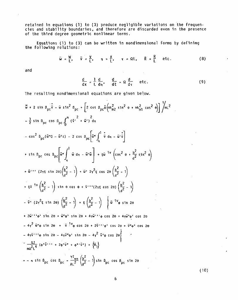
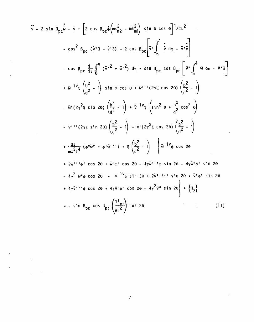
Equat10ns (1) to (3) can be written in nond1mens1onal forms by defin1ng the following relations:
- w w = L'
v v = L'
x n = L' -r = Qt,
R R = L etc.
and
d 1!L dx L dn'
!L t"\L t dt ~'d-r e c.
The resulting nond1mensional equat10ns are g1ven below.
~ , , ,'n Bpe ij - " ,'n' Bpe ' [, co, Bpe. ~k;, ,'n' • , -,;, co,, .)] /-L' TJ 2 2 - t s1n Ilpc cos Ilpc f (v' + w') dTJ
o
- cos2
B (w"Q - w's) - 2 cos B ~w"fl ~ dTJ - w,~] pc pc 11
, "n Bpe co, Bpe[w, £' " d. - w,,,] ,~W ,y (co,' • , :: '.1n' .)
+ w, " (2y~ s1n 2e)(:~ - 1) + wIt 2i~ cos 2e (:~ - 1)
+ ~v 1v (:~ _ 1) s1n e cos e + v"'(2y~ cos 2e) (:~ - ~
- v' (,i~ ,'n ,.) (:~ - ~ ,~(: ~ - ~ I w ,y. "n 2.
+ 2w" 'tf>' s1n 2e + W"tf>" s1n 2e + 4yW" 'tf> cos 2e + 4yW"tf> , cos 2e
2 -". - 1v - -- 4y w tf> s,n 2e + v· tf> cos 2e + 2v' "tf>' cos 2e + V"tf>" cos 2e
- 2 -- 4yv" 'tf> s1n 2e - 4yv"tf> , s1n 2e - 4y v"tf> cos
11 s1n Ilpc cos Ilpc - :)11 (:~ - ~ s1n Ilpc cos Bpc s1n 2e
6
( 8)
(9)
(10)
oJ 1 ImL 2
cos 2 Bpc (ij"Q - ij'S) - 2 cos . ·1 ij dn - v' vJ
- cos Bpe ~, f (v,2 + w,2) dn + sl" Bpe cos Bpe [V" £' w dn - v'w]
+ ;;, 1v~ (:! _ ~ sl" 6 COS 6 + WOO '(2y~ COS 26) (:! -~
- w"(2i~ sl" 26) (:~ - 1) + V 1v~ (Sl"2 6 + :! eos2 ~
( b2 ~ 2 cos 20) (db22 _ l~ - v'" (2yl; s 1 n 20) ,d 2 - } - v" (2y I; ')
+ ~~L4 (~"w· + ~'w"') + ( (:~ - ~ I w 1v~ cos 26
+ 2w" 'cp' cos 20 .. W"cpll cos 20 - 4yW"'cp s1n 20 - 4yw"cp' s1n 20
2 - - 1v - -4y W"cp cos 20 - v cp s1n 20 .. 2v" 'cp' sin 20 + V"cp" sin 20
- - 2- {- } .. 4yv"'cp cos 20 + 4yv"cp' cos 20 - 4y v" s1n 20 .. H2
- sin B cos B (:I2nrr\ cos 20 (11) pc pc AL )
7

~ + f, COS2 Bpc{~ cos 20) + 2f, cos BpC~' sin 0 cos 0 + 2 cos BpC~' (f2 sin2 0
+ f3 cos20) + f4~lV + sln Bpc cos apc I~"t w dn - ~·w - yW
- cos2
Bpc WQ - ~'S) - 2 cos Bpct" t ~ dn - ~.~ - y~)
- f 1 sin Bpc cos BpcWI sin 20 + f V"W" 9
cos 20 + f (W" 2 9
= - f, 2
Bpc sin 0 cos 0 - yS 2 Bpc cos cos ( 12)
where
Q = R{ 1 11) O. 5{ 1 2 S (R + 11), - + - 11 ),
2 _d2 __ ~L_ __Eb2_~ __ . __ .
f3 = km1
= f4 k2 b2 2' m~lk2L 4 12pQ2L \ b2 + d2) + d m m
EAk4 ill.2 + d2} EB 0 12
E 2b4 f5
__ A_ f6
1 ~t _ __ -.n _____ mQ2k2L4
= 12pL 4Q2 mQ2k2L2
= 15pQ2L4{b2 + d2)
m m
_ --.1.§12 4
_J!~!_2 _____ f7
_G.L __ f8
mk}., =
mQ2k2L2 =
pQ2L2{b2 d 2) , k2L2 =
12L2{b2 + d2)
, + m m m
8
fg E(l~~ - I!l!l) E(b2 _ d2}
flO ~ =
~lL2(I + =
p~lL2(b2 + d2)' =
mSlL2' I nn) p ~~
fll ~ (:~ - ~ f 12 EBl Eb4
= pAQ2L6
= 180 pQ2L6 '
EI ~
!l!l pAL4Q2
, a = ~ + Yn, apt = y,
w d (w) and w d (w) = dn = dT ( 13)
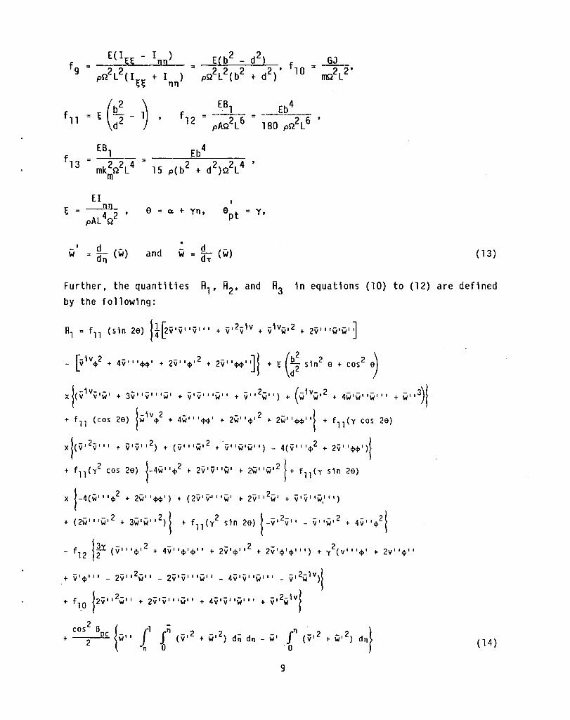
Further, the quant1t1es R1, R2, and R3 1n equat10ns (10) to (12) are def1ned by the follow1ng:
- - - - 2- (-1V- 2 - - -+ v' v' , 'w" + v" w") + w w' + 4w' w' 'w' , ,
- - 2 - ~ 4w' , '<1><1>' + 2w" <1>' + 2w" <1><1>' , ~
X{(V,2VII ' + v'vll2) + (v" 'w,2 + -V"W'W") _ 4(v' "<1>2 + 2V II <l><l>')}
+ f ll (i cos 26) {_4W"<I>2 + 2v'v"w' + 2w"w,2 } + fll
(Y s1n 26)
x {-4(W II '<1>2 + 2W"<I><I>') + (2V'y.II 'w' + 2v" 2W' + V'V"W."')
- - 2 - - 2 ~ 2 j - 2- - - 2 + (2w"'w' + 3w'w" )~ + fll (y s1n 26) 1-v' v" - v"w' - 2~
+ 4v" <I> ~
j3 v - 2 - 2 - 2 f12 12 (v" '<I>' + 4v' '<1>'<1>" + 2ii'<I>" + 2v'<I>'<I>"') + y (v" '<I>' + 2v' '<1>"
+ v' 4>' " - 2 ii' ,2 w" - 2 ii ' ii' , 'w" _ 4 v ' ii' 'w' " _ ii' 2w 1 v)}
+ flO 12ii,,2w" + 2ii'ii"'w" + 4ii'ii"w'" + ii'2w1V}
9
(14)

A j-1V 2 - - 2 - I ! 2 = -fll(cos 20) v 4> + 4V"'4>4>' + 2V"4>' + 2V' 4>4>11
11 - 2-1 v - - - - 3 (.:. - - 3 - I 2- I I + fll (s1n 20) 4 (Wi w + 6W 'W' IWI I I + 2W' I ) + 2V' IVI I IWI + 2' v I W
3 -1-1 I-I I I . + 2v I ii I I IWI I + 2' v v W
+, (:: 5\n2 0' C05
2 0){v",,"2, 3ii'w"w'" 'v"w'w'" ,v'w,wlY}
+ fll(y cos 20) 13v,,2w' + 4V'V"'W' + 5V'V"W" .. v,2w'" ~ 4(W"' 4>2 + 2W"4>4>')
+ (w,2w'" + 2W 'W,,2)! + fll(y2 cos 20) 14VIl4>2 - 2V"V ,2 + 2V 'W'WII!
+ f 11 (y sin 20)14V ' 114>2 + 8v ' 14>4>1 - 3V ' V,,2 2v ,2V' I I .. 2V 'W' 12 t 2V'W'W" I
'V"W'w"! ,fll(i 51n 20) 1-4v'ii"w' , 4w,,~2 - w"ii,2 - w"w,2\
+ f12j(y2)(W'II4>' t W"4>11 - Vl w" 2 - 2VIW"WII) .. ~..Y (W" I4>1 2 .. 2W I 4>I4>")!
f 10 Iv "w" 2 , 2ii 'w"w" 'I ' ~05:~ I Ii" - ii' ,r" (ii,2 , w,2) d"1
H3 = f9 ~4>(WI 12 - Vi 12) cos 20 - 24>V"W" sin 20}
- 2 - 2 -(v I t Wi) dn dn
f h 4>14>1 I + 3Y4>'4>' I - 3y(v ' IWI 14>1 + VIWIII4>1 + VIWII4>II) 1312
(15 )
( 16)
It may be noted here that the last 1ntegral quantit1es 1n equat10ns (14) and (15) ar1se due to the consideration of the third degree terms arising from foreshortening, uF, 1n the tens10n coupl1ng terms (Tw') I and (Tv') I 1n the flapw1se and edgew1se equat1ons, respectively. The terms that are premult1-plied by flO are the third degree non11near terms result1ng 1n the flapwise
10
and edgewise bending equations respectively from consideration of shearing strains in the strain energy variation. Finally, the terms that are premultiplied by f12 in the two bending equations, and those premultiplied by f13 in the torsion equation are the nonlinear terms associated with the sectional constant, EB1. The rest of the terms in equations (14) to (16) are the nonlinear structural terms of third degree, representing the kinematic pitch coupling in the bending and torsion equations (Mills terms).
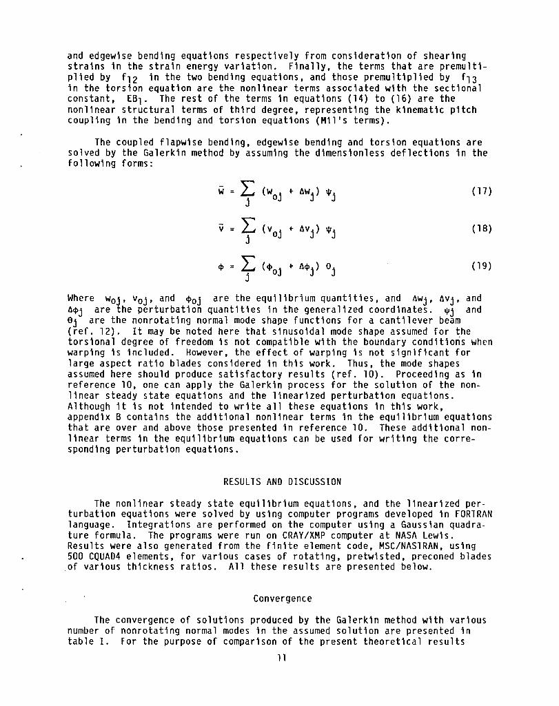
The coupled flapwise bending, edgewise bending and torsion equations are solved by the Galerkin method by assuming the dimensionless deflections in the following forms:
- L (woj + flWj ) "'j w j
( 17)
v = L: (v oj + flV j ) "'j j
( 18)
<I> = L: (<I>oj + ~<I>j) 9j j
(19 )
Where Woj, Voj, and <l>oj are the equilibrium quantities, and ~Wj, ~Vj, and ~<I>j are the perturbation quantities in the generalized coordinates. "'j and 9j are the nonrotating normal mode shape functions for a cantilever beam (ref. 12). It may be noted here that sinusoidal mode shape assumed for the torsional degree of freedom is not compatible with the boundary conditions when warping is included. However, the effect of warping is not significant for large aspect ratio blades considered in this work. Thus, the mode shapes assumed here should produce satisfactory results (ref. 10). Proceeding as in reference 10, one can apply the Galerkin process for the solution of the nonlinear steady state equations and the linearized perturbation equations. Although it is not intended to write all these equations in this work, appendix B contains the additional nonlinear terms in the equilibrium equations that are over and above those presented in reference 10. These additional nonlinear terms in the equilibrium equations can be used for writing the corresponding perturbation equations.
RESULTS AND DISCUSSION
The nonlinear steady state equilibrium equations, and the linearized perturbation equations were solved by using computer programs developed in FORTRAN language. Integrations are performed on the computer using a Gaussian quadrature formula. The programs were run on CRAY/XMP computer at NASA Lewis. Results were also generated from the finite element code, MSC/NASTRAN, using 500 CQUAD4 elements, for various cases of rotating, pretwisted, preconed blades of various thickness ratios. All these results are presented below.
Convergence
The convergence of solutions produced by the Galerkin method with various number of nonrotating normal modes in the assumed solution are presented in table 1. For the purpose of comparison of the present theoretical results
11

obtained from the third degree equations, included in this table are the results from the second degree equations from reference 10, and those obtained from MSC/NASTRAN. In MSC/NAS1RAN calculations 250 or 500 CQUA04 elements were used to model the blade. Furthermore, the centrifugal softening effects were incorporated through suitable OMAP/AL1ER procedures, solution 64 which accounts for differential stiffness effects was used to determine the steady state deflections, and subsequently, solution 63 was used to determine the normal modes and frequencies.
From the convergence pattern of the frequency ratios presented in table I, it can be seen that a five-mode Galerkin solution produces the lowest five coupled mode frequencies that show reasonable agreement with MSC/NASTRAN calculations, and that the accuracy of higher mode frequencies can be increased by increasing the number of nonrotating normal modes in the assumed solutions. Furthermore, a comparison of the results from the third degree equations to those from second degree equations indicates that the accuracy of the third and fourth mode coupled frequencies, (corresponding to predominantly first mode torsional and third mode flatwise bending frequencies, respectively, that are closely coupled for this particular blade configuration) is improved to a considerable extent when the present third degree equations are used.
The convergence pattern of the steady state tip deflections produced by the present beam theory is shown in table II. The agreement of present theoretical results to the corresponding ones from MSC/NAS1RAN is close here also.
Since a five mode solution (n = 5) is found to produce the lowest five coupled mode frequencies and steady state deflections that are in reasonable agreement with the corresponding finite element calculations, further results are generated by using a five-mode Galerkin method solution. Such results are presented and discussed in what follows.
Comparison With Experimental Results
In order to confirm the accuracy of the present theoretical formulation including third degree geometric nonlinearities, results pertaining to typical untwisted and preconed blade cases of thin rotating blades (corresponding to the experimental results reported in ref. 10) are generated. These results are presented in table III together with those obtained from the solution of second degree geometric nonlinear equations and also those from experiment. It should be mentioned here that the elastic modulii used in the theoretical calculations are calibrated values (see ref. 10). A mutual comparison of the three sets of results presented in table III indicates that the results produced by the present, third degree, beam equations are in closer agreement with experimental results than those given by the second degree equations in all cases. Considering the torsional mode frequency (mode 2), it can be seen that the frequency produced by second degree equations for a 22.5° preconed blade with 60° setting angle, and rotating at 3600 rpm, is 489.9 Hz. Corresponding frequency given by the present third degree equations is 563.8 Hz, while the experimental value is 561 Hz. This example illustrates the nature of the third degree geometrically nonlinear elastic terms that are included in the present work. In conclusion, one can state that the results produced by the present set of nonlinear equations are in closer agreement with experimental results than those produced by the second degree equations. Furthermore. a comparison of the results in table III for the particular case of 90° setting angle (blade
12

chord at root section parallel to the axis of rotation) shows that the effect of geometric nonlinearities for this case of setting angle is not significant, confirming the conclusions drawn in references 9 and 10.
Vibration and Stability of Pretwisted, Preconed, Rotating Blades
In order to ascertain the influence of second and third degree geometric nonlinear elastic terms on the coupled frequencies and steady state deflections, parametric studies are conducted for rotating, pretwisted, preconed blades of various thickness ratio. A typical set of such results are presented in table IV(a) for cases of thin blades, and in table IV(b) for cases of thick blades. The variation of frequency ratio with the rotational speed is shown in figure 2 for a 15° preconed, thin, blade.
From an examination of the results presented in table IV(a), it can be seen that the spurious instabilities observed for the case of thin, preconed blades, when only the second degree geometric nonlinearities are included in the equations, are absent when the third degree geometrically nonlinear elastic terms are included to the second degree equations. Furthermore, the quality of results is more accurate when the present third degree equations are used than is the case with those obtained from the second degree equations, even for the stable configurations in both sets of equations.
In order to acquire a further insight into the nature of the third degree geometric nonlinear terms in coupling the modes, one particular case of rota- . ting, untwisted, thin blade with 15° precone is considered. The variation of the frequency ratios of the lowest five coupled modes with a variation of the rotational parameter, Q/wl, is presented in graphical form in figure 2. The curves representing the frequency ratio variations corresponding to predomi-nantly flapwise bending mode frequencies are marked Fl, F2 and F3; and those corresponding to the first torsion mode and the first edgewise bending mode are marked Tl and Sl respectively. A second subscript is used to identify the degree of nonlinearity retained in the equations that produced the corresponding results. Thus, the subscript S denotes the second degree equations and the subscript t denotes third degree equations. From an examination of the results presented in figure 2, it can be seen that the flapwise mode frequencies produced by the second, and the third degree equations are quite close (the differences are not apparent in the graphical representation). For this particular case of thin, untwisted blade, a clear-cut coupling trend of the first torsional and first edgewise modes can be seen in figure 2. When a further comparison of these results is made to those produced by MSC/NASTRAN (shown in figure 2 for discrete values of Q/wl, by the symbol h), it is observed that the third degree equations produce correct coupling trends, and eliminate the torsional instability that is shown by the second degree equations (refer to the curves marked Tl s and Tlt). The edgewise mode frequency predicted by the present third degree equations (Slt) is closer to MSC/NASTRAN results than that predicted by the second degree equations (S1s)-
An examination of the results presented in table IV(b) corresponding to blades of high thickness ratio indicates that the second degree equations have produced the coupled frequencies that are stable for wide ranges of precones, pretwists, and rotational speeds, unlike those in the case of thin blades. However, the accuracy of results obtained by using the present third degree equations is seen to be much superior. It is interesting to note that while
13

reporting the results in reference 10, it was believed that the instability predicted by MSC/NASTRAN for the case of the thick blade (d/b = 0.2, Y = 30°, Bpc = 45°, Q/w1 = 1.0) was a true static instability since the second degree equations also predicted an instability at a similar blade rotational speed. However, while the present third degree equations are used, it is found that there is no such instability at this rotational speed. This observation led the authors to re-examine the results of MSC/NAS1RAN, and re-run the code with different values for the inplane stiffening parameters assigned to the inplane nodes of CQUAD4 elements for eliminating the inplane rotations. It was found that the spurious instability predicted by the solution sequence 64 could be eliminated by an appropriate selection of the in--plane stiffening parameter. The converged set of results from the present beam theory and MSC/NAS1RAN are thus reported in table IV (b) with an appropriate note being made at the bottom of this table. In summary, while MSC/NASTRAN helped in identifying the limitations of second degree geometric nonlinear equations, the third degree geometric nonlinear equations helped in explaining the spurious instabilities, predicted by MSC/NASTRAN in certain cases.
From the mutual comparison of the results produced by the second degree equations, present third degree equations and the corresponding ones from MSC/ NAS1RAN, presented in tables IV(a) and (b), it can be concluded that the spurious instabilities observed in the case of thin blades while using the second degree equations can be removed by incorporating the third degree elastic terms into the equations. Furthermore, the quality and reliability of the results produced by the present third degree equations are much superior to those obtained from second degree equations even in the case of thick blades. For configurations that are more complex than those considered in this work, it may however be necessary to include further nonlinear terms, since it appears from the present investigation (refer tables III and IV), that the second degree elastic terms have a softening effect (or stiffening effect depending on the setting angle and precone) on the torsional modes while the third degree terms have a stiffening (or softening) effect on the torsional modes (thus eliminating the spurious torsional instabilities as shown in table IV(a». While it can be contended from the present investigation that the range of applicability of the nonlinear equations is extended to practical rotor blade operating conditions by the inclusion of the third degree elastic terms, these are by no means, the ultimate form of the equations. Further studies are therefore necessary for making the beam theory equations applicable for more extreme blade configurations.
Finally, it is believed useful to determine the relative importance of the various nonlinear elastic terms of third degree that enter into the equations from the consideration of various primary sources in the variational formulation, such as the normal strain or shearing strains, coupling between tension and bending or torsion etc. Such a study will help in identifying the more important nonlinear terms and in eliminating the relatively less important terms, depending on the type of problem being addressed. To accomplish this objective, results are produced by solving the present beam theory equations by successively discarding one key effect each time, for a few, typical, preconed blade configurations. These results are shown in table V, together with corresponding results from MSC/NASTRAN. Thus, the results presented under the column marked case (1) are obtained from the solution of the third degree nonlinear equations shown by equations (10) to (12). The results presented under the column marked case (2) are obtained by ignoring the third degree nonlinear
14

terms ar1s1ng from the tens10n terms (Tw')' and (Tv')' 1n the two bend1ng equat10ns. It may be noted here, by 1nspect1ng equat10n (4), that these th1rd degree elast1c terms result from the cons1derat1on of foreshorten1ng due to bend1ng, uF, in the tens10n express1on. Results shown under the column marked case (3) are obta1ned by further neglect1ng the th1rd degree nonlinear terms that ar1se from the shearing stra1ns. These terms can be 1dent1fied in equations (A24) and (A25) as those which are associated w1th GJ. Next, by inspecting equations (A24) to (A26) of append1x A, one can find a group of terms 1n each of these equat10ns premult1p11ed by the sectional constant, EB1' These terms were addressed in reference 15, and subsequently 1n reference 16, for spec1alized cases of torsional motion completely uncoupled from bending motions of pretwisted blades. It was established that, under the conditions of completely uncoupled torsional motion, the non11near terms contain1ng the torsional deformation ~ and associated with EB1, are very important. However, their effect in the presence of the kinematic p1tch coup11ng terms 1s not completely understood. In order to ver1fy the 1mportance of the nonlinear terms associated with the sectional constant EB1 1n the presence of Mills terms, results are f1rst produced by 19nor1ng the nonlinear EB1 terms in the two bendlng equations together with those already discarded in case (3). These are presented under the column marked case (4). The results obtained by ignoring all the nonlinear terms assoc1ated w1th EBl 1n the tors1on equation, over and above those d1scarded 1n the previous case, are presented under the column, case (5). F1nally, the results obtained by further d1scarding M1l ' s terms of th1rd degree 1n the two bend1ng equat10ns but retain1ng them 1n the tors10n equation, are presented under the column marked case (6). The last column of table V shows the results produced by the second degree equations addressed in reference 10.
From an exam1nation of these results presented in table V, one can observe that for the blade conf1gurat1ons addressed 1n th1s work, the 1nfluence of th1rd degree elast1c terms ar1s1ng from the foreshorten1ng due to bend1ng, uF, in the bend1ng equat10ns 1s of the order of one to two percent on the steady state deflect10ns and frequencies. These third degree terms are seen to produce a softening effect on the lowest four coupled frequenc1es. Since the correspond1ng nonlinear terms are not 1ncluded in the definition of the tens10n, given 1n equat10n (A28) and used for e11minating ul , in the torsion equation, the exact effect of all these terms 1s not known. However, in v1ew of the close agreement of theoretical results and NASTRAN generated results, (compare results of MSC/NASTRAN to corresponding ones under cases (1) and (2», it is be11eved that the third degree terms arising from tension coupling can safely be 19nored in all the equations consistently. Further, from a comparison of results presented under cases (3) to (5) with the corresponding ones from case (2) and MSC/NAS1RAN, 1t 1s seen that the third degree nonlinear terms arising from shearing stra1ns, and also the nonlinear terms associated with the sectional constant, EB1, produce insign1f1cant changes on the steady-state deflect10ns and on the coupled frequencies. Thus, these nonlinear terms can be discarded for blade configurations addressed in this work. Next, the influence of discarding third degree Mills terms in the bending equations is seen to be quite significant on the steady state deflections and frequencies of pretwisted blades. However, the results pertaining to untwisted blades obtained by discarding third degree Mills terms in bending equations but retaining in the torsion equation are not affected, and remain identical to those obtained from consideration of these terms in all equat10ns. The reason for this would become clear by inspect1ng the steady state deflections for th1s particular case. It can be seen that for th1s particular case of untwisted blade with
15

y = a = 0°, the only significant steady state deflection is w. This gives rise to significant equilibrium coordinates wok and trivial values for vok and ~ok. Furthermore, since a = y = 0, most of the terms in the equations (A24) to (A26) vanish, and the majority of the still remaining terms of third degree will vanish in the perturbation equations due to multiplication of wok with vok or ~ok. However, there appears to be a need for caution in discarding Mil's terms, since, in the presence of aerodynamic forces (which are not addressed in this work), the equilibrium coordinates vok and ~ok may not be trivial. In these or similar circumstances, it would be desirable to retain third degree Mil's terms in all the equations, whether or not the blade is pretwisted.
After identifying the necessity and the importance of the third degree elastic terms as discussed above, there remain certain questions concerning the rationale of the ordering scheme in discarding the inertial terms. As stated in the introduction to this work,and also in appendix A, several nonlinear inertial terms were discarded in reference 10 based upon the ordering scheme followed therein. For consistency of retaining terms when the third degree elastic terms are added to the second degree equations of reference 10, one has to consider the influence of the several inertial terms that were discarded earlier, before any attempts are made to discard these terms in the presence of the third degree elastic terms. In order to answer these questions, at least partially, several inertial terms that were discarded previously of order 0(c 4 ), and arising due to rotational effects (which are not involved with any time derivatives), are added to the present torsion equation. On solving the resulting coupled equations, it is found that the changes in the frequencies were at the fifth significant figure level for alS o preconed, 30 0 pretwisted, rotating, thin blade (d/b = 0.05, Q/wl = 1.0, a = 00
). In view of this observation, it appears rational to discard the large number of higher order inertial terms without losing any appreciable accuracy on the final results.
CONCLUDING REMARKS
The coupled flapwise bending, edgewise bending and torsion equations of dynamic motion of rotating, linearly pretwisted, and large preconed blades of symmetriC cross section including third degree elastic, geometrically nonlinear terms arc derived. These equations are solved by using the Galerkin method and a linear perturbation procedure. Parametric results are generated to ascertain the necessity and the influence of third degree elastic terms. Comparisons of present theoretical results are made to those produced by the finite element code, MSC/NASTRAN, allowing for geometric nonlinear effects; and to those produced from an in-house experimental test rig. Close agreement of the present theoretical results to the corresponding results from other methods is observed for the parametric range studied. The following specific conclusions have emerged in the course of this investigation:
(1) For the dynamic analysis of large preconed blades, the second degree geometric nonlinear equations are not adequate. The validity of beam theory equations can be extended to cover large precones and practical rotational speeds by adding the third degree elastic terms involving the kinematic pitch coupling to the existing second degree equations. It is found that third degree Mills terms counteract the influence of the corresponding second degree terms, and thus, the spurious instabilities that one might observe in the case
16
of th1n, rotat1ng blades wh11e us1ng the second degree ,equations can be suppressed by considering third degree Mills terms. It can thus be concluded that inclusion of at least third degree M11 ls terms 1nto the equations is absolutely necessary. -
(2) For the blade configurat1ons addressed 1n th1s work, the third degree nonlinear elast1c terms resulting from the normal strain are found to be 1mportanto The third degree non11near terms resulting from the shearing strains produce in~ign1ficant changes on the coupled frequencies. Thus, the nonlinear terms of third degree that result from the variation of shearing strains may be neglected 1n the equations of motion. Furthermore, the nonlinear terms associated with the sectional constant, E61, are also found to produce insignif1-cant changes in the steady state deflections and coupled frequencies. In the presence of the third degree Mills terms in the equat10ns, these nonlinear terms may also be discarded.
(3) The present approximation used for defining the tension (only in terms of linear parameters in the equation for T) appears to be adequate. Thus, defining the tension in all the equations consistently in terms of linear variables does not result in any great loss of accuracy in the final iesults.
(4) The influence of higher order inertial terms, other than those retained in the present equations, appears to be insignificant on the final results.
17

APPENDIX A - NONLINEAR CURVATURE EXPRESSIONS AND EQUATIONS OF MOTION
In order to der1ve geometr1c non11near equat10ns, 1t 1s necessary to d1fferent1ate between the deformed and undeformed conf1gurat10ns, and to 1nclude nonlinear terms 1n the stra1n displacement relations. If non11near terms up to third degree are to be cons1dred 1n the equations, one has to der1ve the curvature expressions hav1ng terms up through th1rd degree in the deformation variables and also the th1rd degree nonlinear transformat10n matr1x between the deformed and undeformed blade-fixed coordinates. In arriving at the deformed configuration, one starts with the undeformed configuration and imposes a sequence of rotional transformations on the blade-fixed coord1nates. Thus, deformations u, v, w and ~ d1splace the undeformed blade-fixed coordinate system xoYozo to xyz (fig. 3), and rotate xyz to x3Y3z3 where x3 is tangent to the deformed elastic ax1s. The rotat10n of the tr1ad xyz to the f1nal pos1tion x3Y3z3 may be expressed in terms of the Eulerian type angles. Of the several poss1ble rotat10nal transformation sequences, the one employed here is the flap- lag-p1tch rotat10nal transformation sequence. Further details on the rotational transformation sequences can be found in reference 13. Thus, following an approach identical to that given in reference 13, and retaining terms up through third degree in u, v, w and ~, the non11near curvature expressions are der1ved for a twisted rotor blade underg01ng transverse bend1ng in two planes (flapw1se along the z-zxis, edgewise along the y-axis), extension (u) and torsion (~). In what follows, we present the f1nal equations dispensing w1th all the intermed1ate and lengthy algebra.
When no assumptions are made on the magn1tude of deformat10n the transformat10n matrix between the deformed and undeformed blade fixed coordinates is g1ven by the following equation if nonlinear terms up through th1rd degree are reta1ned:
x y (A 1 )
z
where
_V,2_+ w,2_ 2 2 0.1 " , - 2 + u' (v' + W' ) (A2)
v' - u'v' - v' (v,2 + w,2 2u' ) m, 2 (A3)
w' - u 'WI -w' (v,2 + w,2 2u,2) n, 2 (A4 )
0. 2 -cos Opt {V' . u'v' + ~w' - u'w'~ - d + v' t'2 - v,2 w'2)} 2 2
-. s 1 n e {W' - u 'WI - ~v' + u'v'~ - d + w' (u'2 . w~2)} pt 2 \
(M)
18

Opt {l ,2 £ + u,v,2} sIn Opt {~ - y~ - ~} m2 :. cos '1-- (A6) 2 2 - 2
{~ - v'w' + 2u'v'w' -2
- ~} n2 = cos apt ~ 2
+ sIn Opt {l - w~2 _ ~ + v'w'~ + u'w,2} (Al)
l3 - cos Opt {-w' + v'~ + "'W' _ u'v'~ _ w'u,2 + w;3 + w;./}
v'u,2 ,3
v'w,2 _ ~~} + sIn ° {V' - u'v' + w'~ - u'w'~ + v
(AB) pt 3
{ 2 3} { ,2
+ u'v,2 - ~} m3 v'~ ~ v
(A9) -cos apt ~ - -Z - 6 - s1n apt 1- 2
{l -w,2 2 + u'w,2 + v'W'~} cos apt ~ n3 2 2
+ sin a -~ + v'w' + ~ + p- - 2u'v'w' {
,2 3 } pt 2 6 (A 10)
The d1rect10n cosines given by equations (2) to (10) obey the orthogonality normality cond1tions up to th1rd degree terms.
and
If assumptions correspond1ng to the case of small deformat10ns I discussed in reference 13 are imposed, and terms up through third degree are retained, one obtains the transformation matrix between the deformed and undeformed coor· dinate systems as follows:
x
y
19

In obta1n1ng equat10n (11), 1t 1s assumed that the elongat10ns and shears are negl1g1ble compared to un1ty, and the squares of der1vative of the extens10nal deformat10n of the elast1c axis is negligible compared to the square of bending slopes. The d1rection cosines g1ven 1n equat10n (11) obey the normality and orthogonality cond1t10ns to th1rd degree terms. It may also be noted that the torsion variable, a, is the sum of pretw1st and elast1c twist of the blade at any section. Thus, for a linearly pretw1sted blade w1th total pretwist over the length L of the blade, a at any distance x from the root sect10n 1s g1ven by
a = a + yn + ~ = apt + $
where a 1s the blade setting angle and n = x/L.
(A 12)
The bend1ng curvatures c..>y3 and c..>z3, and the torsional curvature c..>x3 can be obta1ned by using e1ther the direction cosines given earlier, or by using the project10ns of the space derivatives of the rotation angles with respect to the deformed coordinate $3 along the elastic axis of blade. For the case of small deformation level I (ref. 13), the resulting curvature express10ns w1th terms up through third degree in u,v,w, and $, and for flap-lagp1tch transformation sequence of rotations are:
,4,.1 +,4,.1 _ VIWI I c..> x3= 't' pt 't'
cos a _Wi I + $Vll -- VIVI IWI - ---- + ~ {
W"W,2 w112} pt 2 2
+ s 1 n a {v I I pt
+ sin a Wi I - Vll$ t VIVIIW I + --- - -~ {
W"W,2 w,,21 pt 2 2
(A13)
(A14)
(A15 )
If ro and r1 are the undeformed and deformed posit10n vectors of an arb1-trary point on the blade cross section, then the Green's stra1n tensor, Cij, can be obtained from the following equation:
dr1• dr1 - dr 0 • dr 0 = 2 [dS d~ d~j] [c ij ] I:; (A16) d~
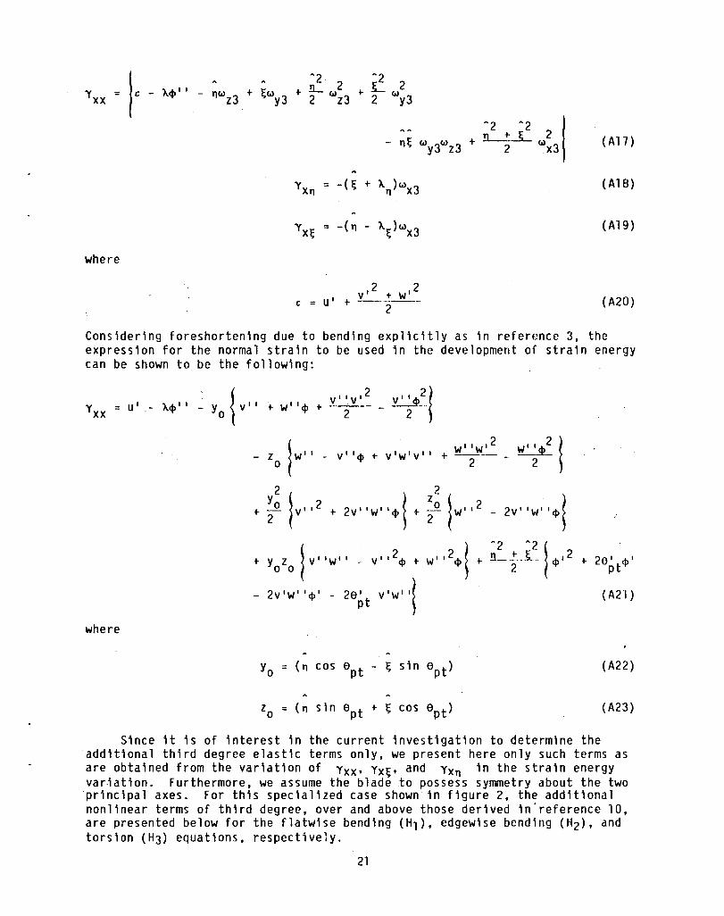
Proceeding on the same l1nes as presented in reference 14, one can obtain the normal strain Yxx and the shear1ng strains YXn and Yx~' In terms of the curvature express10ns, the normal stra1n Yxx, and shearing strains Yx~ and ~xn can be shown as
20
Yxx =
(Al7 )
(AlB)
(A19)
where
2 2 v' -I- W' C = u' -I- --.-----.
2 (A20)
Cons1der1ng foreshortening due to bending explicitly as in reference 3, the expression for the normal stra1n to be used in the development of stra1n energy can be shown to be the following:
where
w"w' Wi' 2 2 ! v"cp -I- v'w'v" -I- -2--- - -2~-
2 2
+ ~o !v,,2 + 2V"W"~! + ~o !w,,2 _ 2v"w' '~!
+ YO'O !v"w" - v,,2~ + w"2~! + ~~;Z!~'2 +
- 2v'w l 'cp' - 2a' v'w' ,i . pt ~
Zo = (n sin apt -I- ~ cos apt)
2e' .pI pt
(A2"1)
(A22)
( A23)
Since it is of interest in the current invest1gation to determ1ne the addit10nal third degree elastic terms only, we present here only such terms as are obtained from the variation of Yxx' yx~, and YXn in the strain energy var.iation. Furthermore, we assume the blade to possess symmetry about the two principal axes. For this specialized case shown 1n figure 2, the additional nonlinear terms of third degree, over and above those derived in'reference 10, are presented below for the flatw1se bend1ng (H1)' edgew1se bend1ng (H2)' and torsion (H3) equat10ns, respectively.
21

Add1t10nal elast1c terms in flapwise bending equation:
Hl [( EIH - E Inn) {-v' '<1,2 v' , 2
t w,2) s1n 6pt = sin 26pt t --2-- (v' cos 6pt
t w' '<1>2 cos 26pt ! t (El~~ sin2 6 t t EI cos2
6 t) (v'v' 'w' p nn p t w,2w' ')
_ ~.:l {36pt V'<I>,2 t 2 6,2
pt (v' <1>' - v' 2w' , ) }] t [GJv' 2w' , ] , ,
- [( EI~~ - EI ) sin 6 cos 6 I v'v,,2 t V"w,w,.! t (El~~ 2 s1n apt nn pt pt
(A24)
Edgewise bendin~
H2 = [(EI~~ - [Inn) I-v' '<1>2 cos 26pt t v'v' 'w' sin 26pt - w, '<1>2 s1n 26pt
t w;~ (v,2 t w,2) sin 6pt cos 6Pd t (ElH cos 2 6pt t El
nn sin2 6pt ) V,2V'II
, , t EI COS
2 6) V'w'w"] - [GJv'w,,2]' nn pt
t Einn sin2 6pt) v'v' ,2 t (EI~~ sin2 6pt t [Inn cos 2 6pt) v' 'w'w"
- E:1 12.p~ w' '010' • 3.pt w' '010,2 - 2.p~ v'w' ,21J - cos~ [V" LL uFdx - v'UF]
(A25)
Torsion:
22
It may be noted that the integral quantities associated with foreshortening, uF, in equations (A24) and (A25) are the third degree nonlinear terms arising from (Tw')' and (Tv')'. Furthermore, the underlined terms in equation (A26)
. 2 are not of third degree. While the term 2a~t ~I was considered in the equa-
tions of reference 10, the term 3a ' pt ~'2 was omitted based upon the ordering scheme followed therein. These terms are rewritten here for the sake of avoiding any confusion. Furthermore, these torsional terms, together with ~'3. were discussed by Houbolt and Brooks (ref. 15). Furthermore, it should be pointed out here that the effect of higher order terms in the kinetic energy on the frequencies and steady state deflections was shown to be of trivial importance in reference 10. Thus, no attempts are made here to obtain the third degree nonlinear expressions pertaining to the variation of the kinetic energy.
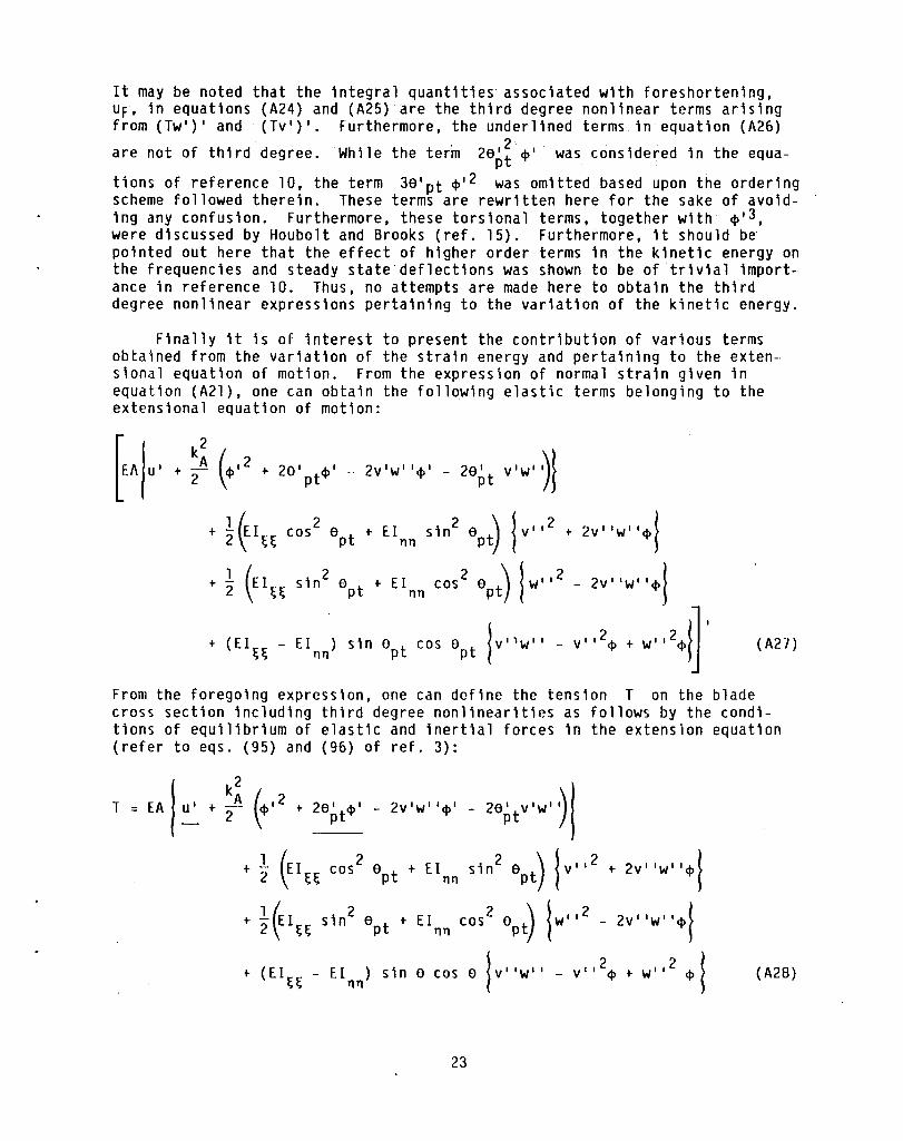
Finally it is of interest to present the contribution of various terms obtained from the variation of the strain energy and pertaining to the extensional equation of motion. From the expression of normal strain given in equation (A21), one can obtain the following elastic terms belonging to the extensional equation of motion:
2V'W' I~I - 2a~t v'w')l
... ~~I~~ cos2
apt'" EInn sin2
apt) {v112 ... 2V' IWII~}
... ~ (EI~~ sin2
apt'" EInn cos2
apt) {w1l2 - 2VIIWII~~
+ (Ei~~ - Ei .. ) sl" Opt cos Opt lv",w" - v' ,2$ + w' ,2$1]' (A21)
From the foregoing expression, one can define the tension T on the blade cross section including third degree nonlinearities as follows by the conditions of equilibrium of elastic and inertial forces in the extension equation (refer to eqs. (95) and (96) of ref. 3):
T - EA 1-"-'- + :~ ($,2 + ~O;'t$ , - 2v 'w' '$' - 20;'t v 'w' )
... ~ (El~~ cos2
Opt'" EInn sin2
apt) {v,,2
... 2v"w"~1 1 f. 2
+ 2\EI~~ sin a + EI cos 2 a ) jW ll2 - 2V I W"",( pt nn pt l ~~
... (EI~~ - EInn) sin a cos a {VIIWII - v1l2~ + W"2 ~} (A28)
23

However, wh1le solv1ng the second degree equat10ns 1n reference 10, only the under11ned terms were reta1ned 1n equat10n (A28) to def1ne the tens1on,and the rest of the second degree geometric nonlinear terms were discarded based upon the ordering scheme employed therein. The resulting equation was used to eliminate u' from the tors10n equation. Even with the inclusion of the 11near term EA k~ e'pt~' in the tension equation, several nonlinear terms result in the torsion equation due to the tension coupling. The effect of all such nonlinear terms was found to be neg11gible on the steady state deflections and the coupled frequencies. In v1ew of th1s observation of reference 10, it is believed that all the nonlinear terms 1n equation (A28) can be safely discarded without affecting the final results to any appreciable extent.
24
APPENDIX B - ADDITIONAL NONLINEAR TERMS IN THE EQUILIBRIUM EQUATlONS
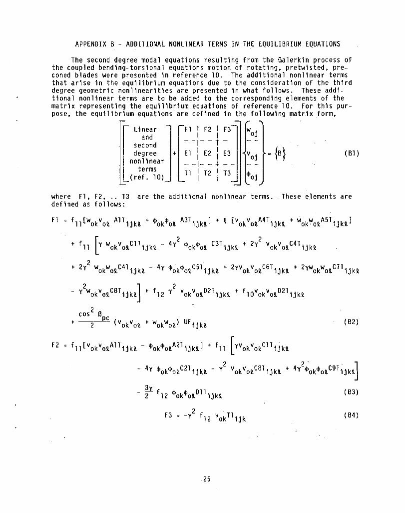
The second degree modal equations resulting from the Galerkin process of the coupled bending-torsional equations motion of rotating. pretwisted. preconed blades were preserited in reference 10. The additional nonlinear terms that arise in the equilibrium equations due to the consideration of the third degree geometric nonlinearities are presented in what follows. These additional nonlinear terms are to be added to the corresponding elements of the matrix representing the equilibrium equations of reference 10. For this purpose. the equilibrium equations are defined in the following matrix form.
Linear Fl I F2 I F3 woj and I I second - --1- - 1 -
degree + El I E2 I E3 voj = {B} ( B1 ) nonlinear I 1
- -1- - -l terms
T1 I T2 1T3 <Poj (ref. 10) I I
where Fl , F2 • .. 13 are the additional nonlinear terms. These elements are defined as follows:
Fl f11[wokVot All ijkt + <Pok<Pot A3T ijkt ] + ~ [vokVotA4Tijkt + wokWotA5Tijkt]
+ fll [Y wokVotC1Tijkt - 4y2 <Pok<Pot C3T ijkt + 2y2 vokVotC41ijkt
2 + 2y wokWotC4Tijkt - 4y <Pok<PotC51ijkt + 2YVokVotC6T;jkt + 2yWokWotC7Tijkt
- y2WokVotCBT;jkt] + f12 y2 vOkVotD2Tijkt + fl0vokVotD21ijkt
cos 2 f3
+ --2.J~ (vokvot + wokwot ) UF ijkt (B2)
F2 fll[vokVotA1Tijkt - <Pok<PotA21ijkt] + fll [YVOkVotC1Tijkt
- 4y <Pok<PotC21ijkt - y2 vokVotCBlijkt + 4y2~Ok<PotC9T1jkt]
h - 2 f12 <Pok<PotDllijkt (B3)
2 F3 = -y f12 VokTlijk (B4 )
25

El = fll [WOkWotA7T;jkt - ~Ok~otA2T;jkt] + fll [_y2 WokwotC8T;jkt
+ 4y2 ~ok~otC9T;jkt - 4Y~ok~otC2T;jkt + y WOkWotD8T;jk~
h + 2 f12~ok~otD6T;jkt (6S)
E2 = fll [4Y ~ok~otCST;jkt - 2y vokvotC7T;jkt + 2y wokwotC6T;jkt
2 2 - y vokwotD3T;jkt + y vokwot04T;jkt + 4y ~ok~otC3T;jkt
- 2y2 vok votC41;jkt + 2y2 WOkWOtC4T;jkt] - y2 f12 WokWotDS1;jkt
2 cos ~
- flO wokwotOST;jkt + ----2 (VokVot t WokWot ) UF;jkt
+ fll [-~ok~otA3T;jkt t VokWotA6T;jkt] + ~ [vokVotA8T;jkt t WOkWotA9Tijk~]
(66)
2 E3 = y f12 WokT4;jk (67)
Tl = 0 (68)
1·2 2 f T8 = y 13 wok ijk (B9)
13
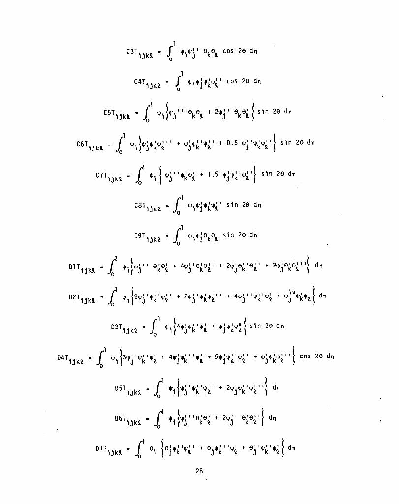
1he integral quantities A1T ijkt ... 08T;jkt appearing in the equations shown
above are defined below.
26

A4Tijkn
= I~ 1\1 ~l\1ll\1ll\1iV + 31\111\11111\111 + 1\1111\11111\11 + 1\1111\1111\111l x. 0 i1 j k i, j k i, j k i, j k i, f
A5T £1 ,I,I,.,iV .. ,I,.,1 + 4,1,1,1,11 • .,111 + .. ,II."II."I.t~b2 sin2 a + cos 2 at d", ijki, = 0 Ti Tj TkTi, TjTk Ti, Tj Tk Ti, f1d 2 f "
A9T I~ . ., 1,.,11 .. ,11 • .,1 I + 3 • .,1 .. ,1 I 1 • .,1 I + .. ,11 • .,1 • .,1 I I .L 'hl,.,I,.,ivt ijki, = 0 Ti Tj Tk Ti, TjTk Ti, Tj TkTi, T TjTkTi, f
ClTijki, = £' 0
C2T ijki, l
a a 1\1 11 1\1 1 I cos 2e dn i j k i,
1\1 11\1 11\1 11\1 1 I I i j k i, + 1\1 11\1 11 1\1 1 I t cos j k i, 2a dn
l\1il"'j 1.lakai, + 21\1j laka~ Icos 2a dn
27
C61 = I~ 1\1 11\1 11\1 11\1 1 I I t 1\111\1111\111 t 0 5 1\1 11 1\1 11\1 1 I} s1n 2a dn 1jk9. 0 ; j k 9. j k 9. • j k 2.
1\1 1\1 11\1 11\1 1 I s1n 2a dn ; j k 9.
DlT;jkll = I~ 1\1 11\1 1 I I alai t 41\1 1 lala l I t 21\1 1a l la l I t 21\11alal I It dn ~ 0 1 j k 9. j k 9. j k 9. j k 9. ~
D41;jkll = £1 1\1 j31\11 11\1 1 11\1 1 t 41\1 11\1 1 I 11\1 1 t 51\111\1111\1 1 I t 1\1 11\1 11\1 1 I I t cos 2a dn ~ 0 i1 j k 9. j k 9. j k 9. j k 9. ~
D51;jkll. I~ 1\1 ~I\II 11\1 11 1\1 1 1 t 21\1 11\1 11 1\1 1 I It dn o ;1 j k II. j k 9. ~
D61;jkll. - f~ 1\1 ~I\II I lala l t 21\1 1 I alai It dn - 0 ;} j k II. j k II. ~
28

~
Uf = i 1\11\111
ijkl 0 1 j [~.l f.~ (1\Ill\Ildn) k l
1\1 lell\ll I I + 2e l 11\1 1 I .. e l I 11\1 1 t do 1 j k j k j kf
1\1 (e"l\l" + ell\llll) do 1 j k j k
The perturbation equations can now be written by inspecting the equilibrium equations presented above and by proceeding as in reference 10.
29

A
{B}
B1
b,d
d/b
E
F 1 ,F 2 •.• T3
1,j,k,i.
L
m
n
O(c)
P
R
S,S3
T
APPENDIX C - NOMENCLATURE
cross-sectional area of blade
vector
section constant
breadth and thickness of blade
thickness rat10
Young's modulus
elements of matrix representing equilibrium equations (see appendix B)
coefficients (see eq. (13»
modulus of r1gidity
area moments of inertia about major and minor princ1pal centroidal axes
dummy indices
tors10nal stiffness constant
blade cross-sectional polar radius of gyration
blade cross-sectional mass radius of gyration
length of blade
direction cosines
mass of blade per un~t length
number of nonrotat1ng normal modes for each of the flapwise bending, edgewise bend1ng, and tors10nal deflections
small parameter of the order of bend1ng slopes (= W, V or ~)
natural radian frequency
radius of disc
position vectors of a point on the blade elastic ax1s, before and after deformation, respectively
coordinate along the elastic axis before and after deformation, respect'lvely
blade tension
30

t t1me
u,v,W d1splacements of arb1trary p01nt on the elast1c ax1s 1n x,y,z d1rect1ons, respect1vely
uF foreshorten1ng due to bend1ng (see equat10n 5)
VOj,Woj,toj steady-state ~qu1l1br1um quant1t1es
v,w,t steady-state d1mens1onless equ1libr1um d1splacements
x runn1ng coord1nate along x-ax1s
xoyozo blade-f1xed ax1s system at arb1trary p01nt on elast1c ax1s before deformation
XVZ coord1nate system w1th or1g1n at hub (d1sc) center l1ne which rotates with blade such that x-axis l1es along the undeformed position of the elast1c ax1s
xyz blade-f1xed axis system which translates w1th respect to xoyozo
y,z centroidal principal axis of beam cross section
x3Y3z3 blade-fixed orthogonal axis system in deformed configuration obta1ned by rotating xyz; x3 axis 1s tangent to the deformed elastic axis
Q setting angle (collective pitch)
Bpc precone angle
Y total pretw1st of the blade over its length
Yxx'Yxn'Yx~ engineering strain components
~Vj,~Wj,~tj perturbation quant1ties
c extensional component of Green's strain tensor
Cij Green's stra1n tensor
n dimens10nless length coordinate, x/L
n,~ sectional coordinates along major andminor principal axes for a given point, respectively
a Euler1an-type rotation angle in appendix A, eq. (A12), where a = Q + Yn + t = apt + t
a geometr1c pitch angle 1n equations (1) to (16) and in append1x B (a = apt = Q + yn)
31
p
T
( ) I
( )
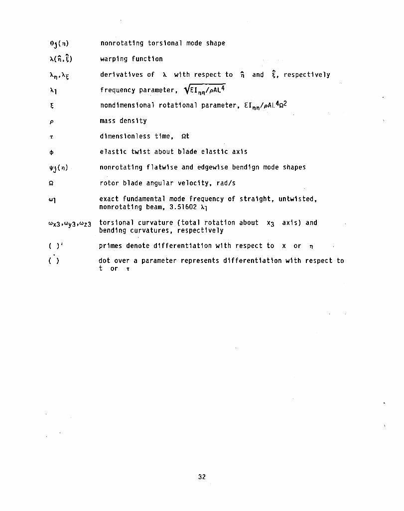
nonrotating torsional mode shape
warping function
derivatives of ~ with respect to nand ,.. ~, respectively
frequency parameter, 1{El nn /pAL4
nondimensional rotational parameter, El nn /pAl.4Q2
mass dens Hy
dimensionless time, Qt
elastic twist about blade elastic axis
nonrotating flatwise and edgewise bendign mode shapes
rotor blade angular velocity, rad/s
exact fundamental mode frequency of straight, untwisted, nonrotating beam, 3.51602 ~1
torsional curvature (total rotation about bending curvatures, respectively
x3 axis) and
primes denote differentiation with respect to x or n
dot over a parameter represents differentiation with respect to t or T
32

REFERENCES
1. Hodges, D.H.; and Dowell, E.H.: Nonlinear Equations of Motion for theElastic Bending and Torsion of Twisted Nonuniform Rotor Blades. NASA TN 0-7818, 1974.
2. Rosen, A.; and Friedmann, P.P.: Nonlinear Equations of Equilibrium for Elastic Helicopter or Wind Turbine Blades Undergoing Moderate Deformation. (UCLA-ENG-77l8, University of California, Los Angeles; NASA Grant NSG-3082) NASA CR-159478, 1978.
3. Kala, K.R.V.; and Kvaternik, R.G.: Nonlinear Aeroelastic Equations for Combined Flapwise Bending, Chordwise Bending, Torsion, and Extension of Twisted Nonuniform Rotor Blades in Forward Flight. NASA TM-74059, 1977.
4. Crespo da Silva, M.R.M.: Flap-Lag-Torsional Dynamic Modeling of Rotor Blades in Hover and in Forward Flight, Including the Effect of Cubic Nonlinearities. (ASD-81-6-1, Cincinnati University; NASA Grant NAG2-38) NASA CR-166194, 1981.
5. Hodges, D.H.: Nonlinear Equations for Dynamics of Pretwisted Beams Undergoing Small Strains and Large Rotations. NASA TP-2470, 1985.
6. Mehmed, 0., et al.: Bending-Torsion FLutter of a Highly Swept Advanced Turboprop. NASA TM-82975, 1981.
7. Srinivasan, A.V.; Kielb, R.E.; and Lawrence, C.: Dynamic Characteristics of an Assembly of Prop-Fan Blades. ASME Paper No. 85-G1-134, Mar. 1985.
8. Subrahmanyam, K.B.; and Kala, K.R.V.: Vibration and Buckling of Rotating, Pretwisted, Preconed Beams Including Coriolis Effects. Vibration of Blades and Bladed Disk Assemblies, R.E. Kielb and N.F. Rieger, eds., ASME, 1985, pp. 75-87.
9. Subrahmanyam, K.B.; and Kala, K.R.V.: Nonlinear FLap-Lag-Extensional Vibrations of Rotating, Pretwisted, Preconed Beams Including Coriolis Effects. Developments in Mechanics, vol. 13, Proceedings of 19th Midwestern Mechanics Conference, The Ohio State UniverSity, Columbus, Ohio, 1985, pp. 110-112.
10. Subrahmanyam, K.B., et al.: Nonlinear Bending-Torsional Vibration and Stability of Rotating, Pretwisted, Preconed Blades Including Coriolis Effects. NASA TM-87207, 1986.
11. Mil, M.L.: Helicopters: Calculation and Design, Vol. I, Aerodynamics. NASA Tl-F-494, 1967, pp. 430-432.
12. Chang, Tish-Chun; and Craig, R.R., Jr.: On Normal Modes of Uniform Beams. University of Texas, Engineering Mechanics Laboratory, EMRL-1068, 1969.
13 .. Kvaternik, R.G.; and Kala, K.R.V.: Nonlinear Curvature Expressions for Combined Flapwise Bending, Chordwise Bending, Torsion and Extension of Twisted Rotor Blades. NASA TM-X-73997, 1976.
33

14. Kaza, K.R.V.: Non11near Aeroe1ast1c Equat10ns of Mot10n of Tw1sted, Nonun1form, Flexible Horizontal-Axis Wind Turb1ne Blades. NASA CR-159502, 1980.
15. Houbo1t, J.C.; and Brooks, G.W.: Differential Equations of Motion for Combined F1apwise Bending, Chordwise Bending, and Torsion of Twisted Nonuniform Rotor Blades. NACA Report 1346, 1958.
16. White, W.F. Jr.: The Influence of High Twist on the Dynamics of Rotat1ng Blades. Fourth European Rotocraft and Powered Lift Aircraft Forum, Associaz10ne Ita1iana di Aeronautica ed Astronautica, Italy, 1985, pp. 25-1 to 25- 13.
34

TABLE I. - CONVERGENCE PATTERN OF FREQUENCY RATIOS (PIAl) OF PRETWISTED, PRECONED, ROTATING BLADE INCLUDING THIRD DEGREE GEOMETRIC NONLINEARITIES AND CORIOLIS EFFECTS
[d 0 0 0 - L !l J b = 0.05, Bpc = 15 , y = 30 , tt = 0 , R = 0, d = 200, ;1 = 0.50.
Mode Results from perturbation solution: Galerkin method number (Third degree equations)
tn = 1 n = 2 n = 3 n = 4 n = 5 n = 6 n = 7 n = 8
1 6.7837 4.0123 3.9880 3.9820 3.9813 3.9802 3.9804 3.9805 2 65.0281 40.0635 20.4535 20.1407 20.0567 20.0226 20.0116 20.0073 3 74.0808 63.7502 60.0351 57.6998 57.2708 57.0335 56.9803 56.9702 4 ------- 89.2954 85.0776 63.6660 63.0034 62.9864 62.9480 62.9221 5 ------- 216.1802 137.8281 86.8464 86.3469 86.3378 86.2964 86.2841 6 ------- 438.2073 214.4627 214.0674 124.1565 121.6039 121.2614 120.9963 7 ------- -------- 351.9987 275.0052 214.0269 204.4178 200.0460 199.5745 8 ------- -------- 457.2028 350.2601 249.5374 214.1014 213.9084 213.9329
tn represents the number of nonrotating normal modes used in the generalized coordinates.
TABLE II. - CONVERGENCE PATTERN OF STEADY STATE TIP
DEFLECTIONS FROM BEAM THEORY INCLUDING THIRD
DEGREE GEOMETRIC NONLINEARITIES, AND
COMPARISON WITH MSC/NASTRAN RESULTS
[d 0 0 0 - !l J -b = 0.05, B = 15 , y = 30 , tt = 0 , R = 0, -- = 0.50. pc w1
Method Number of Steady state tip deflection assumed (centerline deflection)
modes or CQUAD4 - -elements w v ~
n = 1 -0.018444 0.00182864 -0.00429201 n = 2 -.0547506 .00661266 -.00088087 n = 3 -.0545014 .00585071 -.00086910
Galerkin n = 4 -.0547382 .00587672 -.00081777 n = 5 -.0547296 .00584699 -.00081642 n = 6 -.0547554 .00584616 -.00083679 n = 7 -.0547519 .00584231 -.00083540 n = 8 -.0547560 .00584234 -.000831394
MSC/ 500 CQUAD4 -.0543090 .00583720 -.000902900 NASTRAN Elements
Second MSC/NASTRAN degree (500 CQUAD4
equations elements) (Ref. 10)
n = 8
3.9699 3.9923 19.9823 20.0707 51. 6155 57.7069 60.1018 64.5911 85.5334 86.1357
120.8147 121.1038 199.2196 199.4268 204.6820 219.5793

TABLE III. - COMPARISON OF THEORETICAL AND EXPERIMENTAL RESULTS
[~= 0.05, ~ = 60, y = 0·, L = 152.4 mm (6.0 in), E = 222.7 GPa, G = 95.1477 GPa,
p = 2.02728x10⁻⁸ k9/ mm3]
Precone Sett in9 Rotational Method Natural frequency, Hz angl e angle speed !lpc' a, n,
degree degree rpm Mode 1 Mode 2 Mode 3 Mode 4
0 30 3600 (a) 126.4 582.2 623.9 1683.4 (b) 126.5 576.2 625.7 1689.3 (c) 129.0 570.0 630.0 1688.0
4800 (a) 146.5 588.7 647.0 1700.4
~~~ 146.6 578.4 651.9 1717.0 146.0 582.0 665.0 1716.0
6000 (a) 168.6 597.0 673.4 1714.1 (b) 168.9 581.5 684.0 1751. 3 (c) 166.0 587.0 706.0 ------
22.5 60 1200 (a) 96.5 572.5 593.4 1655.3 ~b ) 96.5 573.3 593.6 1656.2 c) 97.0 574.0 ----- ------
3600 (a) 111.5 489.9 625.2 1569.0 (b) 114.4 563.8 622.9 1625.7 (c) 124.4 561.0 626.0 -----
45 0 870 (a) 94.8 570.2 591.0 1653.1 ~b ) 94.9 573.7 591.3 1653.9 c) 95.9 574.0 588.0 1655.0
1506 (a) 96.3 541.0 593.0 1655.0 (b) 96.5 572.7 593.8 1657.3 (c) 98.6 569.0 589.0 1662.0
22.5 90 2400 (a) 101.4 574.3 603.5 1665.4 (b) 101.5 574.1 603.7 1666.0 (c) 101.9 571.4 602.9 1664.0
4800 (a) 120.1 573.3 644.2 1700.6 (b) 120.0 573.2 644.4 1701.2 (c) 121.2 562.0 654.0 1684.0
6000 (a) 131.8 572.3 673.3 1721.9 ~b ) 131.7 572.2 673.4 1722.5 c) 134.5 553.0 688.0 1695.0
«a))Theoretical results excluding third degree geometric nonlinearities (Ref. 10).
(b) Present theoretical results incuding third degree geometric nonlinearities. c Experimental results (Reference 10).
Mode 5
1825.8 1813.0 1807.0
1837.4 1815.8 1817.0
1853.3 1819.9 ------
1796.3 1796.2 1798.0
1684.5 1696.7 ------
1780.5 1783.6 1799.0
1675.0 1696.8 1803.0
1815.8 1815.3 1799.0
1836.1 1835.7 1826.0
1855.1 1854.7 1854.0

TABLE IV(a). - COMPARISON OF FREQUENCY RATIOS OF PRECONED, ROTATING BLADES OF LOW THICKNESS RATIO
[ 0 - L ]
a = 0 , R = 0, b = 10.
d y, Ilpc, n Method Frequency ratio, 0 degree degree wI
Mode 1 Mode 2 Mode 3
0.05 0 15 1.0 (a) unstable ------- -------(b) 5.1562 23.9231 42.5942 (c) 5.1781 23.7926 44.2514
, 2.0 ( a) unstable ------- -------
~~~ 8.2498 28.5806 37.0869 8.3385 28.3445 39.0512
0.05 30 15 0.8 (a) unstable ------- -------(b) 4.6283 20.4636 50.6977 (c) 4.6363 20.5566 52.6995
1.0 ( a) unstable ------- -------
~b) 5.1485 20.7221 47.2311 c) 5.1656 20.9982 49.2750
0.05 30 45 0.3 (a) 3.5517 19.7350 54.1394 (b) 3.5652 19.7493 57.4509 (c) 3.5762 19.7675 57.6886
0.5 (a) Unstable ------- -------
~b) 3.6965 19.3873 46.4173 c) 3.7167 19.7195 48.1580
0.06 0 45 0.3 (a) 3.5438 22.1084 50.2454 (b) 3.5541 22.1433 52.2279 (c) 3.5665 22.1613 52.9289
0.5 ( a) Unstable ------- -------
~b ) 3.7123 22.4986 39.1497 c) 3.7055 22.2822 40.7961
1.0 (a) Unstable ------- -------(b) 4.8283 20.6450 24.8709 (c) 4.8169 22.2298 23.0175
((a))Beam theory including second degree qeometric nonlinearities.
(b) Beam theory including third dgree geometric nonlinearities. c Results from MSC/NASTRAN.
pIAl
Mode 4
-------64.0009 63.4078
-------69.5140 68.0883
-------61.8649 61.7111
------62.3392 61.8346
60.3105 63.2751 65.1148
-------60.6038 60.3879
61.7771 61.8699 61.8449
-------62.5760 61. 7824
-------67.6783 61.1692
Mode 5
-------90.3709 88.2218
-------89.9382 87.6030
-------91.1574 91.3101
-------92.4586 92.8652
84.9439 85.8371 85.5516
-------94.1009 94.5271
72.2320 74.9998 74.6194
-------86.6498 85.4823
-------94.9696 94.4257

TABLE IV(b). - COMPARISON OF FREQUENCY RATIOS OF PRECONED, ROTATING BLADES OF HIGH THICKNESS RATIO
o - L [a = 0 , R = 0, b = 10.]
d y, Spc, rl Method Frequency ratio, 0 degree degree wI
Mode 1 Mode 2 Mode 3
0.10 30 15 2.0 (a) 8.2940 19.6256 29.0720 (b) 8.2418 22.1184 35.5968 (c) 8.3177 22.8858 35.5153
0.20 30 15 1.0 (a) 5.1411 15.4978 26.0439 ~b) 5.1538 15.5377 26.3139 c) 5.1619 15.5424 26.0745
0.20 30 45 1.0 (a) 0.1533 7.2997 19.0724 (b) 4.8045 13.1377 26.5609 (c)t 4.8128 13.5546 24.5559
0.25 0 45 1.0 (a) 4.6184 10.6218 23.2097 (b) 4.8283 12.2162 24.8709 (c) 4.8122 12.3085 23.0257
0.25 30 45 1.0 (a) 4.5877 10.5075 23.2236 ~b ) 4.8175 11. 7024 25.9483 c) 4.8046 11.8666 23.9928
((a))Beam theory including second degree geometric nonlinearities.
(b) Beam theory including third d9ree geometric nonlinearities. c Results from MSC/NASTRAN.
pIAl
Mode 4
64.0094 67.5836 64.3812
60.8242 61.3437 60.7458
54.6244 62.3999 58.1445
59.4123 67.6783 61.0894
56.6582 61.1655 57.2734
tSpurious instability was shown by MSC/NASTRAN in reference 10 due to inadequate inplane fixing stiffness parameter value.
Mode 5
72.7573 78.0812 77.5158
67.1784 69.0699 70.4579
63.4657 75.6008 74.3679
62.8856 68.7724 67.1483
63.7352 71.9986 70.3849
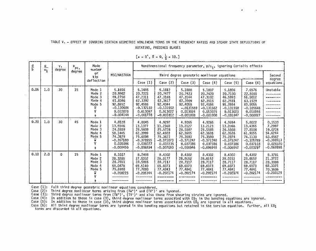
TABLE V. - EFFECT OF IGNORING CERTAIN GEOMETRIC NONLINEAR TERMS ON THE FREQUENCY RATIOS AND STEADY STATE DEFLECTIONS OF ROTATING, PRECONED BLADES
[a = 0', ~ = 0, ~ = 10.]
d 1'1 y, Ilpc, Mode Nondimensional frequency parameter, p/~l' ignoring Coriolis effects b wI degree degree number
or MSC/NASTRAN Third degree geometric nonlinear equations tip deflection Case (1) Case (2) Case (3) Case (4) Case (5) Case (6)
0.05 1.0 30 15 Mode 1 5.1656 5.1485 5.1812 5.1808 5.1807 5.1806 7.0576 Mode 2 20.9982 20.7221 20.7477 20.7423 20.7420 20.7130 22.5000 Mode 3 49.2750 47.2311 47.3168 47.3144 47.3102 46.5993 51.5012 Mode 4 61.8346 62.3392 62.3617 62.3509 62.3515 62.2591 63.1529 Mode 5 92.8652 92.4586 92.4044 92.4058 92.4084 91.0954 89.9055
W -0.130684 -0.132132 -0.131552 -.0131559 -0.131562 -0.131558 -0.105646 v 0.012878 0.013097 0.013022 0.013024 0.013025 0.013023 0.010946 ~ -0.004148 -0.001778 -0.001812 -0.001808 -0.001808 -0.001847 -0.000827
0.20 1.0 30 45 Mode 1 4.8128 4.8045 4.9297 4.9265 4.9265 4.9264 5.8022 Mode 2 13.5546 13.1377 13.2568 13.2127 13.2123 13.2066 13.4365 Mode 3 24.5559 26.5609 25.5728 26.5587 26.5585 26.5568 27.8104 Mode 4 58.1445 62.3999 62.4503 62.3605 62.3606 62.3526 61.9055 Mode 5 74.3679 75.6008 75.3623 75.3583 75.3590 75.2874 74.1130
W -0.357180 -0.378955 -0.371073 -0.371247 -0.371248 -0.371247 -0.321789 Ii 0.035096 0.038377 0.037235 0.037386 0.037386 0.037386 0.037118 ~ -0.009450 -0.006834 -0.007093 -0.006946 -0.006945 -0.006942 -0.000297
0.10 2.0 0 15 Mode 1 8.3327 8.2498 8.4302 8.4302 8.4302 8.4302 8.4302 Mode 2 28.3285 27.8202 28.0177 28.0152 28.0152 28.0152 28.0152 Mode 3 28.7811 28.5806 28.7117 28.7117 28.7117 28.7117 28.7117 Mode 4 68.0478 69.5140 69.6073 69.6073 69.6073 69.6073 69.6073 Mode 5 75.6988 77.7080 77.4843 77.4841 77.4841 77.4841 77.4841
W -0.200225 -0.205344 -0.202174 -0.202174 -0.202174 -0.202174 -0.202174 Ii --------- --------- --------- --------- --------- --------- ---------~ --------- --------- --------- --------- --------- --------- ---------
--------- ----- ----
Case (1): Full third degree geometric nonlinear equations considered. Case (2): Third degree nonlinear terms arising from (TW')' and (TV')' are ignored. Case (3): Third degree nonlinear terms from (TW')', (TV')' and also those from shearing strains are ignored.
Second degree
equations
Unstable --------------------------------------------------------
0.1533 7.2997
19.0724 54.6244 63.4567 -0.398513
0.028370 -0.069898
8.3781 21.3722 28.3088 68.3325 70.3606 -0.203129 ------------------
-
Case (4): In addition to those in case (3), third degree nonlinear terms associ ted with EB1 in the bending equations are ignored. Case (5): In addition to those in case (3), third degree nonlinear terms associated with EB1 are ignored in all equations. Case (6): All third degree nonlinear terms are ignored in the bending equations but retained in the torsion equation. Further, all EB1
terms are discarded in all equations.

\ I Q \ \j) \ I \ ~Pc I y-J \ I \ I \ I
/ /
/
/ /
/
IY
/ ~ -.;;;;;: -.:, x
........ "-\ ---___ ~Precone
, --- angle, ~P L Undeformed -_ c
blade
Figure 1. - Blade coordinate system and definition of blade parameters.
100
60 '\
g 50 \ \ c..
.~ .. ~ ,., u c: '" ::l
~ u...
\ 40 \ ------.t::>Tlt
\ 30
1" 30 ~-Tl 28 \ s
26 24 \ 22 \ -;-10 \ 8 6
\
4
2 0 .4 .8 1.2
Rotational parameter, Q/IJI
Figure 2. - Comparison of frequency ratios predicted by various methods
(~= 0 05 a = II> = ao "'" = 150 if = 0\ \b . . , "rC ' 'j Fl, F2' F3 are flatwise modes (subscript s denotes solution of second degree equations and t denotes solution of third degree equations), and Tl and 51 are first torsional and edgewise bending modes, respectively; Do indicates the result produced by M5C/NA5TRAN.

z
z
y
\ X'Xo \~Undeformed
blade
Figure 3. - Schematic representation of undeformed and deformed blade for flap-Iagpitch rotational transformation sequence.

1. Report No. 2. Government Accession No.
NASA TM-87307 4. Title and Subtitle
Influence of Th1rd-Degree Geometric Nonlinearities on the Vibration and Stab11ity of Pretwisted. Preconed. Rotating Blades
7. Author(s)
K.B. Subrahmanyam and K.R.V. Kaza
9. Performing Organization Name and Address
Nat10na1 Aeronautics and Space Admin1stration Lewis Research Center Cleveland. Ohio 44135
12. Sponsoring Agency Name and Address
Nat10na1 Aeronautics and Space Administration Washington. D.C. 20546
15. Supplementary Notes
3. Recipient's Catalog No.
5. Report Date
May 1986 6. Performing Organization Code
505-63-11 8. Performing Organization Report No.
E-2988
10. Work Unit No.
11. Contract or Grant No.
13. Type of Report and Period Covered
Techn1ca1 Memorandum
14. Sponsoring Agency Code
K.B. Subrahmanyam. on leave from NBKR Institute of Science and Technology. mechanical Engineering Dept .• Vidyanagar 524413. India and presently Senior Research Associate. University of Toledo. Mechanical Engineering Dept .• Toledo. Ohio 43606; K.R.V. Kaza. NASA Lewis Research Center.
16. Abstract
This report is concerned with the study of the influence of third degree geometric nonlinear terms on the vibration and stability characteristics of rotating. pretwisted. and preconed blades. The govern1ng coupled f1apwise bending. edgewise bending. and torsional equations are derived including third-degree geometr1c nonlinear elastic terms by making use of the geometric nonlinear theory of elasticity in which the elongations and shears are negligible compared to unity. These equations are specialized for blades of doubly symmetric cross section with linear variation of pretwist over the blade length. The nonlinear steady state equations and the linearized perturbation equations are solved by using the Galerkin method. and by utilizing the nonrotating normal modes for the shape functions. Parametric results obtained for various cases of rotating blades from the present theoretical formulation are compared to those produced from the finite element code MSC/NASTRAN. and also to those produced from an in-house experimental test rig. It is shown that the spurious instab1lities. observed for thin. rotating blades when second degree geometric nonlinearities are used. can be elim1nated by including the third-degree elastic nonlinear terms. Furthermore. inclusion of third degree terms improves the correlation between the theory and experiment.
17. Key Words (Suggested by Author(s»
Nonlinear bending-torsional vibration; Stability; Third-degree geometric non~inearities. Pretwist; Precone; Rotation
18. Distribution Statement
Unclassified - un11mited STAR Category 39
19. Security Classif. (of this report)
Unclassified 20. Security Classif. (of this page)
Unclassified 21. No. of pages
"For sale by the National Technical Information Service, Springfield, Virginia 22161
22. Price"

End of Document