influence of pile rake angle on the seismic response of...
TRANSCRIPT
Proceedings of the 9th International Conference on Structural Dynamics, EURODYN 2014
Porto, Portugal, 30 June - 2 July 2014
A. Cunha, E. Caetano, P. Ribeiro, G. Müller (eds.)
ISSN: 2311-9020; ISBN: 978-972-752-165-4
733
ABSTRACT: Even though inclined piles have traditionally been used to withstand large horizontal loads, the lack of
understanding about their response under seismic loads (or under associated loads derived, for instance, from soil settlement or
liquefaction) have prevented their use in seismic regions. However, several authors have showed that inclined piles may provide
potential benefits with respect to the seismic response of the superstructure and of the foundation itself. For this reason, the
dynamic response of this type of foundations is now being studied. The kinematic interaction factors of pile foundations with
inclined elements is one of the aspects that have not received enough attention. The influence of pile rake angle on the seismic
response of the superstructure is another aspect that still needs more research. These are precisely the two aspects on which this
paper will focus. In order to compute kinematic interaction factors, a three-dimensional boundary element – finite element
coupling formulation is used. The system is excited by harmonic vertically-incident shear waves. The paper presents kinematic
interaction factors corresponding to inclined single piles, and square 2 by 2 and 3 by 3 pile groups in ready-to-use dimensionless
format. It is shown that, while the kinematic response of inclined single piles is rather independent of the rake angle, the
kinematic restriction of the pile cap produces a significant dependence on that factor: horizontal displacements are reduced with
the rake angle, while rotation changes sign for a certain configuration and increases significantly afterwards. These results can
be used to compute the response of a superstructure by substructuring in order to study further the influence of rake angle on it.
KEY WORDS: Pile Group; Battered Piles; Kinematic Interaction Factors; Soil-Structure Interaction.
1 INTRODUCTION
Inclined piles have traditionally been used in foundations
when lateral resistance is required to transmit horizontal loads.
However, the lack of understanding about their response
under seismic loads have prevented their use in seismic
regions and many codes require that such piles be avoided
[1][2]. Nevertheless, several authors have showed that
inclined piles may provide potential benefits with respect to
the seismic response of the superstructure and of the
foundation itself [3][4][5]. Furthermore, field evidences
suggesting relevant beneficial effects concerning the use of
raked piles has been recollected [6][7].
The beneficial or detrimental role of foundations including
inclined piles has not been yet clarified. For this reason, the
dynamic response of this type of foundations needs further
research. The kinematic interaction factors of foundations
consisting of vertical piles have been broadly studied
[8][9][10][11][12][13]. However, the kinematic interaction
factors of pile foundations with inclined elements have not
received enough attention. On the other hand, the influence of
pile rake angle on the seismic response of the superstructure is
another aspect that still needs more research. This paper
focuses on these two aspects and provide kinematic
interaction factors needed to carry out substructuring analyses.
Some authors have performed analysis of the kinematic
interaction factors of deep foundations with vertical piles (e.
g. [14][15]). However, up to the authors’ knowledge, only
Giannakou [16] has presented kinematic interaction factors of
inclined piles for groups of 2 x 1 piles.
In this line, this paper presents kinematic interaction factors
of single raked piles, as well as those of 2 x 2 and 3 x 3 groups
with battered elements. In order to obtain these results, a
three-dimensional boundary element (BEM) – finite element
(FEM) coupling formulation is used where the soil is modeled
as a homogeneous viscoelastic isotropic half spaced by
boundary elements, and the piles are modeled as Euler-
Bernoulli beams, embedded in the soil, by monodimensional
finite elements. Coupling is performed by equilibrium and
compatibility conditions. The system is excited by harmonic
vertically-incident shear waves. The main trends of the
influence of the rake angle on the kinematic interaction factors
are deduced from the presented results. Moreover, a procedure
based on a substructuring methodology [20] is used herein to
analyze the influence of the rake angle on the maximum
response value of a superstructure supported on piles.
2 METHODOLOGY
2.1 BEM-FEM model
In this work, the kinematic interaction factors of pile
foundations are numerically obtained by using a BEM-FEM
coupling model [18][19].
The boundary element method is used herein to model the
dynamic response of the soil region taking into account the
internal loads arising from the pile-soil interaction. The piles
rigidity is introduced later into the system by using finite
elements. The whole approach is depicted in Figure 1.
The soil is considered as a linear, homogeneous, isotropic,
viscoelastic half-space. The boundary integral equation for a
time-harmonic elastodynamic state defined in this region with
Influence of pile rake angle on the seismic response of pile foundations
and piled structures
Cristina Medina, Juan José Aznárez, Luis A. Padrón, Orlando Maeso
Instituto Universitario de Sistemas Inteligentes y Aplicaciones Numéricas en Ingeniería (IUSIANI), Universidad de Las
Palmas de Gran Canaria, Edificio Central de Parque Científico y Tecnológico del Campus Universitario de Tafira, 35017, Las
Palmas de Gran Canaria, Spain.
e-mail: {cmedina, jjaznarez, lpadron, omaeso}@siani.es, web: http://www.siani.es
Proceedings of the 9th International Conference on Structural Dynamics, EURODYN 2014
734
boundary can be written in a condensed and general form
as
(1)
where is the local free term matrix at collocation point ‘k’,
and represent the displacement and the traction fields in
the three directions of space, and are the elastodynamic
fundamental solution tensors due to a time-harmonic
concentrated load at point ‘k’, is the number of piles, and
represents the pile-soil interface along the load-line . In
Equation (1), the two terms between brackets represent the
contribution of the internal loads, being a point load
placed at the tip of the pile and the distribution of
interaction loads, along the pile shaft, applied on a line
defined by the pile axis. On the other hand, represents the
corresponding tensor computed at the tip of the pile.
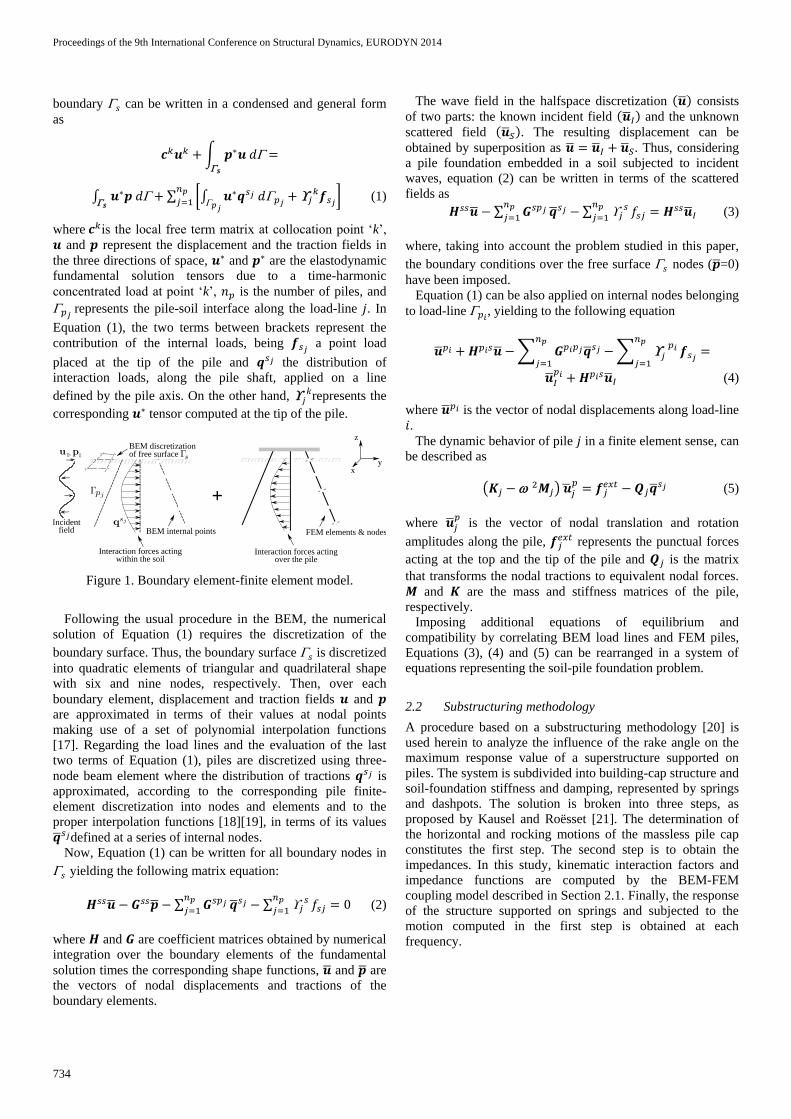
Figure 1. Boundary element-finite element model.
Following the usual procedure in the BEM, the numerical
solution of Equation (1) requires the discretization of the
boundary surface. Thus, the boundary surface is discretized
into quadratic elements of triangular and quadrilateral shape
with six and nine nodes, respectively. Then, over each
boundary element, displacement and traction fields and
are approximated in terms of their values at nodal points
making use of a set of polynomial interpolation functions
[17]. Regarding the load lines and the evaluation of the last
two terms of Equation (1), piles are discretized using three-
node beam element where the distribution of tractions is
approximated, according to the corresponding pile finite-
element discretization into nodes and elements and to the
proper interpolation functions [18][19], in terms of its values
defined at a series of internal nodes.
Now, Equation (1) can be written for all boundary nodes in
yielding the following matrix equation:
(2)
where and are coefficient matrices obtained by numerical
integration over the boundary elements of the fundamental
solution times the corresponding shape functions, and are
the vectors of nodal displacements and tractions of the
boundary elements.
The wave field in the halfspace discretization consists
of two parts: the known incident field and the unknown
scattered field . The resulting displacement can be
obtained by superposition as . Thus, considering
a pile foundation embedded in a soil subjected to incident
waves, equation (2) can be written in terms of the scattered
fields as
(3)
where, taking into account the problem studied in this paper,
the boundary conditions over the free surface nodes ( =0)
have been imposed.
Equation (1) can be also applied on internal nodes belonging
to load-line , yielding to the following equation
(4)
where is the vector of nodal displacements along load-line
. The dynamic behavior of pile in a finite element sense, can
be described as
(5)
where is the vector of nodal translation and rotation
amplitudes along the pile, represents the punctual forces
acting at the top and the tip of the pile and is the matrix
that transforms the nodal tractions to equivalent nodal forces.
and are the mass and stiffness matrices of the pile,
respectively.
Imposing additional equations of equilibrium and
compatibility by correlating BEM load lines and FEM piles,
Equations (3), (4) and (5) can be rearranged in a system of
equations representing the soil-pile foundation problem.
2.2 Substructuring methodology
A procedure based on a substructuring methodology [20] is
used herein to analyze the influence of the rake angle on the
maximum response value of a superstructure supported on
piles. The system is subdivided into building-cap structure and
soil-foundation stiffness and damping, represented by springs
and dashpots. The solution is broken into three steps, as
proposed by Kausel and Roësset [21]. The determination of
the horizontal and rocking motions of the massless pile cap
constitutes the first step. The second step is to obtain the
impedances. In this study, kinematic interaction factors and
impedance functions are computed by the BEM-FEM
coupling model described in Section 2.1. Finally, the response
of the structure supported on springs and subjected to the
motion computed in the first step is obtained at each
frequency.
Proceedings of the 9th International Conference on Structural Dynamics, EURODYN 2014
735
3 RESULTS
3.1 Problem description
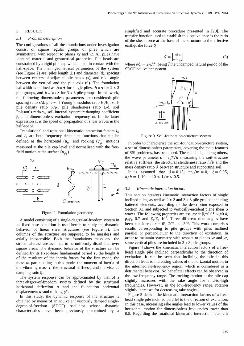
The configurations of all the foundations under investigation
consist of square regular groups of piles which are
symmetrical with respect to planes xy and yz. All piles have
identical material and geometrical properties. Pile heads are
constrained by a rigid pile-cap which is not in contact with the
half-space. The main geometrical parameters of the system
(see Figure 2) are: piles length (L) and diameter (d), spacing
between centers of adjacent pile heads (s), and rake angle
between the vertical and the pile axis (). The foundation
halfwidth is defined as b = d for single piles, b = s for 2 x 2
pile groups, and 2/3sb for 3 x 3 pile groups. In this work,
the following dimensionless parameters are considered: pile
spacing ratio s/d, pile-soil Young’s modulus ratio Ep/Es, soil-
pile density ratio ρs/ρp, pile slenderness ratio L/d, soil
Poisson’s ratio νs, soil internal hysteretic damping coefficient
βs and dimensionless excitation frequency ω. In the latter
expression cs is the speed of propagation of shear waves in the
half-space.
Translational and rotational kinematic interaction factors
and are both frequency dependent functions that can be
defined as the horizontal ( ) and rocking (
) motions
measured at the pile cap level and normalized with the free-
field motion at the surface ( ).
Figure 2. Foundation geometry.
A model consisting of a single-degree-of-freedom system in
its fixed-base condition is used herein to study the dynamic
behavior of linear shear structures (see Figure 3). The
columns of the structure are supposed to be massless and
axially inextensible. Both the foundations mass and the
structural mass are assumed to be uniformly distributed over
square areas. The dynamic behavior of the structure can be
defined by its fixed-base fundamental period , the height
of the resultant of the inertia forces for the first mode, the
mass participating in this mode, the moment of inertia of
the vibrating mass , the structural stiffness, and the viscous
damping ratio .
The system response can be approximated by that of a
three-degree-of-freedom system defined by the structural
horizontal deflection and the foundation horizontal
displacement and rocking In this study, the dynamic response of the structure is
obtained by means of an equivalent viscously damped single-
degree-of-freedom (SDOF) oscillator whose dynamic
characteristics have been previously determined by a
simplified and accurate procedure presented in [20]. The
transfer function used to establish this equivalence is the ratio
of the shear force at the base of the structure to the effective
earthquake force
(6)
where , being the undamped natural period of the
SDOF equivalent system.
Figure 3. Soil-foundation-structure system.
In order to characterize the soil-foundation-structure system,
a set of dimensionless parameters, covering the main features
of SSI problems, has been used. These include, among others,
the wave parameter measuring the soil-structure
relative stiffness, the structural slenderness ratio and the
mass density ratio between structure and supporting soil.
It is assumed that , , ,
and .
3.2 Kinematic interaction factors
This section presents kinematic interaction factors of single
inclined piles, as well as 2 x 2 and 3 x 3 pile groups including
battered elements, according to the description exposed in
Section 3.1 and subjected to vertically-incident plane shear S
waves. The following properties are assumed: βs=0.05, νs=0.4,
ρs/ρp=0.7 and Ep/Es=103. Three different rake angles have
been considered: =10º, 20º and 30º. This work comprises
results corresponding to pile groups with piles inclined
parallel or perpendicular to the direction of excitation. In
order to maintain symmetry with respect to planes xz and yz,
some vertical piles are included in 3 x 3 pile groups.
Figure 4 shows the kinematic interaction factors of a free-
head single pile inclined perpendicular to the direction of
excitation. It can be seen that inclining the pile in this
direction leads to increasing values of the horizontal motion in
the intermediate-frequency region, which is considered as a
detrimental behavior. No beneficial effects can be observed in
the low-frequency range. The rocking motion at the pile cap
slightly increases with the rake angle for mid-to-high
frequencies. However, in the low-frequency range, rotation
slightly increases for decreasing rake angles.
Figure 5 depicts the kinematic interaction factors of a free-
head single pile inclined parallel to the direction of excitation.
In this case, increasing rake angles lead to lower values of the
horizontal motion for dimensionless frequencies lower than
0.5. Regarding the rotational kinematic interaction factor, it

Proceedings of the 9th International Conference on Structural Dynamics, EURODYN 2014
736
can be seen that there are no significant differences with
respect to the results shown in Figure 4 indicating that, in the
case of single piles, this factor is almost independent of the
direction of inclination.
Figure 6 and Figure 8 illustrate the influence of the rake
angle on the kinematic interaction factors of a 2 x 2 and a 3 x
3 pile group, respectively, with piles inclined perpendicular to
the direction of excitation. In both cases, it can be seen that
inclining piles in this direction leads generally to higher
values of the translational kinematic interaction factor in
comparison with those obtained with vertical piles. A modest
increase of rotation with the rake angle is observed in the
intermediate frequency range.
Figure 4. Kinematic interaction factors of a single pile
inclined perpendicular to the direction of excitation with
different rake angles , L/d=15 and L/b=15. Ep/Es=103.
Figure 7 and Figure 9 shows the influence of the rake angle
on the kinematic interaction factors of a 2 x 2 and a 3 x 3 pile
group, respectively, with piles inclined parallel to the
direction of excitation. The use of piles inclined in this
direction results in a reduction of the horizontal motion in the
low-to-mid frequency range. However, rotation increases with
the rake angle. It should be noted that when pile groups
include piles inclined parallel to the direction of excitation,
horizontal free-field ground motion and cap rotation become
out of phase.
Figure 10 shows the rotational kinematic interaction factor
of a 3 x 3 pile group with piles inclined parallel to the
direction of excitation for two different values of the pile-soil
Young’s modulus ratio. Opposite to what occurs with vertical
piles, higher stiffness ratios Ep/Es yields smaller cap rotations.
In order to illustrate the influence of the pile slenderness
ratio on the rotation at pile cap, Figure 11 depicts the
rotational kinematic interaction factor of a 3 x 3 pile group
with piles inclined parallel to the direction of excitation for
three different values of L/d. It can be seen that, in contrast to
what occurs for vertical piles, lower pile slenderness ratios
lead to decreasing rocking motions at the pile cap in a low-
frequency range.
Figure 5. Kinematic interaction factors of single piles inclined
parallel to the direction of excitation with different rake angles
, L/d=15 and L/b=15. Ep/Es=103.

Proceedings of the 9th International Conference on Structural Dynamics, EURODYN 2014
737
Figure 6. Kinematic interaction factors of 2 x 2 pile groups
with piles inclined perpendicular to the direction of excitation
with different rake angles , s/d=7.5, L/d=15 and L/b=2.
Ep/Es=103.
Figure 7. Kinematic interaction factors of 2 x 2 pile groups
with piles inclined parallel to the direction of excitation with
different rake angles , s/d=7.5, L/d=15 and L/b=15.
Ep/Es=103.
Figure 8. Kinematic interaction factors of 3 x 3 pile groups
with piles inclined perpendicular to the direction of excitation
with different rake angles , s/d=5, L/d=15 and L/b=2.
Ep/Es=103.
Figure 9. Kinematic interaction factors of 3 x 3 pile groups
with piles inclined parallel to the direction of excitation with
different rake angles , s/d=5, L/d=15 and L/b=2. Ep/Es=103.

Proceedings of the 9th International Conference on Structural Dynamics, EURODYN 2014
738
Figure 10. Influence of the pile-soil modulus ratio Ep/Es on the
rotational kinematic interaction factor of a 3 x 3 pile group
with s/d=5, L/d=15, L/b=2 and piles inclined parallel to the
direction of excitation.
Figure 11. Influence of the pile slenderness ratio L/d on the
rotational kinematic interaction factor of a 3 x 3 pile group
with L/b=2 and piles inclined parallel to the direction of
excitation. Ep/Es=103.

Proceedings of the 9th International Conference on Structural Dynamics, EURODYN 2014
739
3.3 Maximum structural shear forces
Figure 12 illustrates the influence of the rake angle on the
maximum structural response value for a 2 x 2 pile group with
piles inclined parallel to the direction of excitation. It should
be noted that, for short and squat buildings with h/b=1, the
value of decreases as the rake angle increases due to the
reduction of the translational kinematic interaction factor,
which predominates in this case. However, for high buildings
with h/b=10, the controlling factor is that associated to
rotation which increases with the rake angle and consequently
leads to higher values of .
Figure 12. Maximum structural response value for 2 x 2
pile groups with piles inclined parallel to the direction of
excitation with different rake angles , s/d=7.5, L/d=15 and
L/b=2. Ep/Es=103.
4 CONCLUSIONS
In this paper, an analysis of the influence of using pile groups
with inclined piles, in two different directions and with three
different rake angles, is accomplished. For this purpose,
kinematic interaction factors of single piles, as well as 2 x 2
and 3 x 3 pile groups has been obtained using a boundary
element-finite element methodology in which piles have been
considered to be embedded in a homogeneous half-space and
subjected to vertically incident plane shear S waves.
The main conclusions extracted from the analysis of the
results shown in Section 3 are summarized below.
The influence of the rake angle on the kinematic
interaction factors strongly depends on the direction of
inclination of piles except in the case of single battered
piles where the rotational kinematic interaction factor is
almost independent of pile inclination.
Deep foundations including piles inclined parallel to
the direction of excitation have a beneficial role in the
low-to-mid frequency range leading to lower values of
the horizontal displacement. The opposite occurs when
piles are inclined perpendicular to the direction of
excitation.
Cap rotation increases with the rake angle and becomes
out of phase with the horizontal free-field ground
motion when inclining piles parallel to the direction of
excitation.
Opposite to what occurs with vertical piles, higher
stiffness ratios Ep/Es yields smaller cap rotations when
considering configurations with elements inclined
parallel to the direction of excitation.
In contrast to what occurs for vertical piles, when
considering deep foundations including piles inclined
parallel to the direction of excitation, lower pile
slenderness ratios lead to decreasing values of the
rocking motion at the pile cap in a low-frequency
range.
The influence of the rake angle on the maximum
structural shear force depends on the structural
slenderness ratio. For high buildings (h/b=10) it
increases with the rake angle. The opposite occurs for
short and squat building (h/b=1).
Results in terms of translational and rotational kinematic
interaction factors are provided for the purpose of allowing
to compute the response of a superstructure by
substructuring in order to study further the influence of rake
angle on it.
ACKNOWLEDGMENTS
This work was supported by the Subdirección General de
proyectos de Investigación of the Ministerio de Economía y
Competitividad (MINECO) of Spain and FEDER through
research project BIA2010-21399-C02-01 and also by the
Agencia Canaria de Investigación, Innovación y Sociedad de
la información (ACIISI) of the Government of the Canary
Islands and FEDER through research project ProID20100224.
Cristina Medina is a recipient of a fellowship from de
Program of predoctoral fellowships of the University of Las
Palmas de Gran Canaria (ULPGC). The authors are grateful
for this support.
REFERENCES
[1] Association Française du Génie Parasismique. Recommandations AFPS
90 pour la rédaction de règles relatives aux ouvrages et installations à
réaliser dans les régions sujettes aux séismes, Presses de l’Ecole
National des Ponts et Chaussées, Vol.1, Chapters 1-9, Paris, 1990.
[2] European Committee for Standardization, Eurocode 8: Design of
structures for earthquake resistance. Part 5: Foundations, retaining
structures and geotechnical aspects, Brussels, 2004.
[3] J. Guin, Advances in soil-pile-structure interaction and non-linear pile
behavior, Ph.D. Thesis. State University of New York at Buffalo, 1997.
[4] M. Sadek and I. Shahrour, Three-dimensional finite element analysis of
the seismic behavior of inclined micropiles. Soil Dynamics and
Earthquake Engineering, Vol. 24(6), pp. 473-485, 2004.
[5] N. Gerolymos, A. Giannakou, I. Anastasopoulos and G. Gazetas,
Evidence of beneficial role of inclined piles: observations and summary
of numerical analyses. Bulletin of Earthquake Engineering, Vol. 6(4),
pp. 705-722, 2008.
[6] G. Gazetas and G. Mylonakis, Seismic soil-structure interaction: new
evidence and emerging issues. In Geotechnical Earthquake Engineering
and Soil Dynamics III ASCE, Geotechnical Special Publication II, pp.
1119-1174, 1998.
[7] J.B. Berrill, S.A. Christensen, R.P. Keenan, W. Okada and J.R. Pettinga,
Case study of lateral spreading forces on a piles foundation.
Géotechnique, Vol. 51(6), pp. 501-517, 2001.
[8] G. Gazetas, K. Fan, T. Tazoh, K. Shimizu, M. Kavvadas and N. Makris,
Seismic pile-group-structure interaction. Geotechnical Special
Publication ASCE, Vol. 34, pp. 56-93, 1992.
[9] S. M. Mamoon and S. Ahmad, Seismic response of pile to obliquely
incident SH, SV and P waves, Journal of Geotechnical Engineering,
Vol. 116, pp. 186-204, 1990.
[10] S. M. Mamoon and P. K. Banerjee, Response of piles and pile groups to
travelling SH-waves, Earthquake Engineering and Structural Dynamics,
Vol. 19, pp. 597-610, 1990.
[11] K. Fan, G. Gazetas, A. M. Kaynia, E. Kausel and S. Ahmad, Kinematic
seismic response of single piles and pile groups, J Geothec Eng Div,
ASCE, Vol. 117(12), pp. 1860-1879, 1991.
Proceedings of the 9th International Conference on Structural Dynamics, EURODYN 2014
740
[12] M. Kavvadas and G. Gazetas, Kinematic seismic response and bending
of free-head piles in layered soil. Géotechnique, Vol. 43, pp. 207-222,
1993.
[13] A. M. Kaynia and E. Kausel, Dynamic stiffness and seismic response of
pile groups. Technical Report R83-03, MIT, Cambridge, MA, 1982.
[14] M. Sadek and I. Shahrour, Influence of the head and tip connection on
the seismic performance of micropiles. Soil Dynamics and Earthquake
Engineering, Vol. 26, pp. 461-468, 2006.
[15] N. Deng, R. Kulesza and F. Ostadan, Seismic soil-pile group interaction
analysis of a battered pile group. In Proceedings of the 4th International
Conference on Earthquake Geotechnical Engineering, Thessaloniki, in
CD-ROM, 2007.
[16] A. Giannakou, Seismic behavior of inclined piles. Ph.D. Thesis,
National Technical University of Athens, 2007.
[17] J. Domínguez. Boundary elements in dynamics. Computational
Mechanics Publications & Elsevier Applied Science Southampton, NY,
1993.
[18] L. A. Padrón, J. J. Aznárez and O. Maeso. BEM-FEM coupling model
for the dynamic analysis of piles and pile groups. Engineering Analysis
with Boundary Elements, Vol. 31, pp. 473-484, 2007.
[19] L. A. Padrón. Numerical model for the dynamic analysis of pile
foundations. Ph. D. Thesis, University of Las Palmas de Gran Canaria.
(available for download at http://hdl.handle.net/10553/2841)
[20] C. Medina, J. J. Aznárez, L. A. Padrón and O. Maeso, Effects of soil-
structure interaction on the dynamic properties and seismic response of
piled structures. Soil Dynamics and Earthquake Engineering, Vol. 53,
pp. 160-175, 2013.
[21] E. Kausel and J. M. Roësset, Soil-structure interaction for nuclear
containment, in: Electric Power and Civil Engineer. Power Div. ASCE
Specialty Conf, Boulder, Colorado, pp. 469-498, 1974.