influence of niobium on mechanical properties and hot
TRANSCRIPT

Influence of Niobium on mechanical properties and hot crack susceptibility of Nickel-base cored-wire weld metal type 70/20 and 70/15
G. Posch1, R. Vallant2, W. Klagges1, H. Cerjak 2
1Böhler Schweißtechnik Austria GmbH, Kapfenberg, Austria
2 Institute for Materials Science, Welding and Forming, Graz University of Technology, Austria
ABSTRACT In the last years new types of welding electrodes are strongly evolving on the market: Flux-cored wires (FCW) and Metal-cored Wires (MCW) as replacement for the solid wire in the standard gas metal arc welding (GMAW) process. These new types are produced by filling in various metal and/or mineral powders into a tube or a rolled strip before drawing to diameters equivalent to those of solid wires used for GMAW. Using this technique the benefits of slag systems process and easy variation of alloying concepts known from the shielded metal arc welding (SMAW) process can be applied to the very economic GMAW welding process with additional advantages in the welding behaviour. This paper explains in short the production technology and possibilities of nickel base cored wires and deals with the influence of different Nb/C-ratios on the hot cracking susceptibility and mechanical properties especially in nickel base 70/20 and 70/15 weld metals. Using the PVR-hot cracking test facility and tensile testing an optimum Nb/C-ratio could be found to minimize the hot cracking susceptibility at requested mechanical properties. At least the achieved results of different nickel-base cored wire weld metals will be set into relation to weld metals achieved with the SMAW and the solid wire GMAW process.
Welding
Common used welding processes The most often used welding processes are Manual Metal Arc (MMA), Metal Inert Gas/ Metal Active Gas (MIG/MAG); Flux Cored Wire (FCW) and Submerged Arc Welding (SAW). All these welding processes use an electric arc to melt base and filler metal. MMA and SAW use beside solid wire as filler material also slag and shielding gas-forming components to optimise metallurgy, welding characteristics and for protecting the arc and weld surface. But they are limited in their use by low efficiency or restrictions in the possible welding position. MIG/MAG uses a solid wire as filler and external provided shielding gases for protecting the arc. This process is known as a highly economic, all position weldable process. But due to missing slag forming components many benefits can not be applied to this process. FCW as the “latest” development of the standard welding processes combines the benefits of slag forming components and the high efficiency of the MIG/MAG process by using tubular wires which are filled with slag forming components. As it can be seen in the market survey of Europe from 1975-2000 (Fig. 1) the market share of MMA is continuously decreasing while MIG/MAG increases, FCW is slightly increasing. Comparing the European market with US and Japan, the tendency is similar, only the market share of FCW is much more important in US and Japan.
Flux- and Metal Cored wires As already mentioned FCW combines the benefits of welding processes which use slag forming components and the high efficiency of the MIG/MAG process by using tubular wires which are filled with slag forming compounds and special alloying powders. If only alloying elements and no slag forming compounds in the filling are used, the tubular wire is known as metal cored wire (MCW). In this case the easy modification of the alloying concept is mandatory. In Fig. 2 the production technology of FCW and MCW is shown.
Principles of Welding The main principle of welding is melting the base materials to form a common melt pool. To improve the joint or to fill up the joint filler metal can be added. After solidification of the weld pool the joint is formed. Due to the fact that welding is a process with a localized high heat input caused by an electric arc or another high energetic source (e.g. laser), an inhomogeneous temperature field is build up near heat source (Fig. 3). This temperature field affects also the base material near the joint and metallurgical effects in the base metal can take place. If the temperatures are high enough to cause microstructural changes in the base metal the region is called “heat affected zone”. Beside various microstructural effects also high internal stresses are built up by the temperature field caused by welding.
Cracking in Nickelbasis-weldments
Solidification cracking All metals show a typical dependence between ductility and temperature (Fig. 4): increasing temperature in the solid state up to the solidus temperature (TS) leads to a higher ductility. But above TS a sharp decrease in ductility due to the presence of a second, liquid phase occurs. This region is called the Brittle Temperature Range (BTR). If stresses are applied within the BTR, solidification cracking can take place. To minimize the BTR and in further consequence to prevent solidification cracking the presence of elements, which can form phases with low melting points should be avoided. Such elements are for example sulphur, phosphorus, bismuth and antimony. During cooling from the liquid weld pool these critical phases remain as a liquid at the solidification front (Fig. 5). Additional stresses, caused by the inhomogeneous welding temperature field can lead to hot cracking. Comprehensive investigations [2] have shown, that the solubility of these critical elements at high temperatures is higher in cubic body-centered lattices compared to cubic face-centered structures. This explains the high hot cracking sensitivity of nickel-base alloys.
Liquification cracking Liquification cracking can occur, if hot cracking sensitive materials are heated up to temperatures above the melting point of the low melting critical phases but below the “main” solidification temperature of the alloy. Also in this case, stresses can lead to cracking.
Ductility dip cracking High chromium nickel-base alloys show in a temperature range between 0,6 - 0,8xTS a solid-state grain boundary embrittlement phenomenon which is called Ductility Dip Cracking (DDC) (Fig. 6).

The mechanism of Ductility Dip Cracking (DDC) is till now not completely understood, but various investigations [3] have shown, that fine particles at the grain boundaries, especially carbides of type M23C6 can prevent grain boundary gliding and in further consequence the formation of voids and small cracks along grain boundaries (Fig. 7).
Testing of hot cracking behaviour For the quantification of the hot crack susceptible of weld metals the controlled deformation crack test or controlled flat tension test (PVR-test) was developed [4, 5, 6]. The test procedure of the PVR-test uses flat specimens of base metal or all-weld metal, clamped into a special tension fixture of a horizontal servohydraulic tensile test equipment (Fig. 8). The specimen is loaded by a linear increased tension speed (Fig. 9). This tensioning is superposed by a constant moving welding arc. The standard PVR-test procedure is carried out with tension rates linearly increasing from zero to 60mm/min, using bead-on-plate TIG-welding with Argon shielding gas at various heat inputs.
For quantification of the hot cracking susceptibility the critical tension speed (vcr) or critical elongation speed (CES) is determined. The CES should correspond to the first hot crack, detected visually at a specified magnification. It can be determined for each of the hot crack types: Solidification cracks (SC), Liquation cracks (LC) and Ductility Dip Cracks (DDC). In Fig. 10 the surface of a PVR test specimen after testing is shown. The different types of hot cracks can easily be dedected.
Experimental procedures
Design of filler material The aim of this work was to determine the appropriate Niobium- and carbon content for flux- and metal cored wires. Because of the novelty of this kind of filler material no standards are available till now from which the chemistry of the weld metal can be derived. In Fig. 11 various standards for filler metals and different welding processes of type 70/15 and 70/20 are listed. It can be seen, that the specifications regarding carbon and niobium content are different depending on the applied welding process. And compared to the base metal the specification is also not exactly comparable. To investigate the influence of different Niobium- and Carbon contents in the weld metal, various cored wires with different chemical composition were produced, welded and compared with the results of already on the market existing flux-cored wires and fillers for other welding processes. To evaluate the influence of Nb and C the other alloying elements (Cr, Mn, Mo) were kept constant in the laboratory-produced cored wires (Fig. 12). Thereby Cr was at about 20%, Mn was around 3% and no Mo was added.
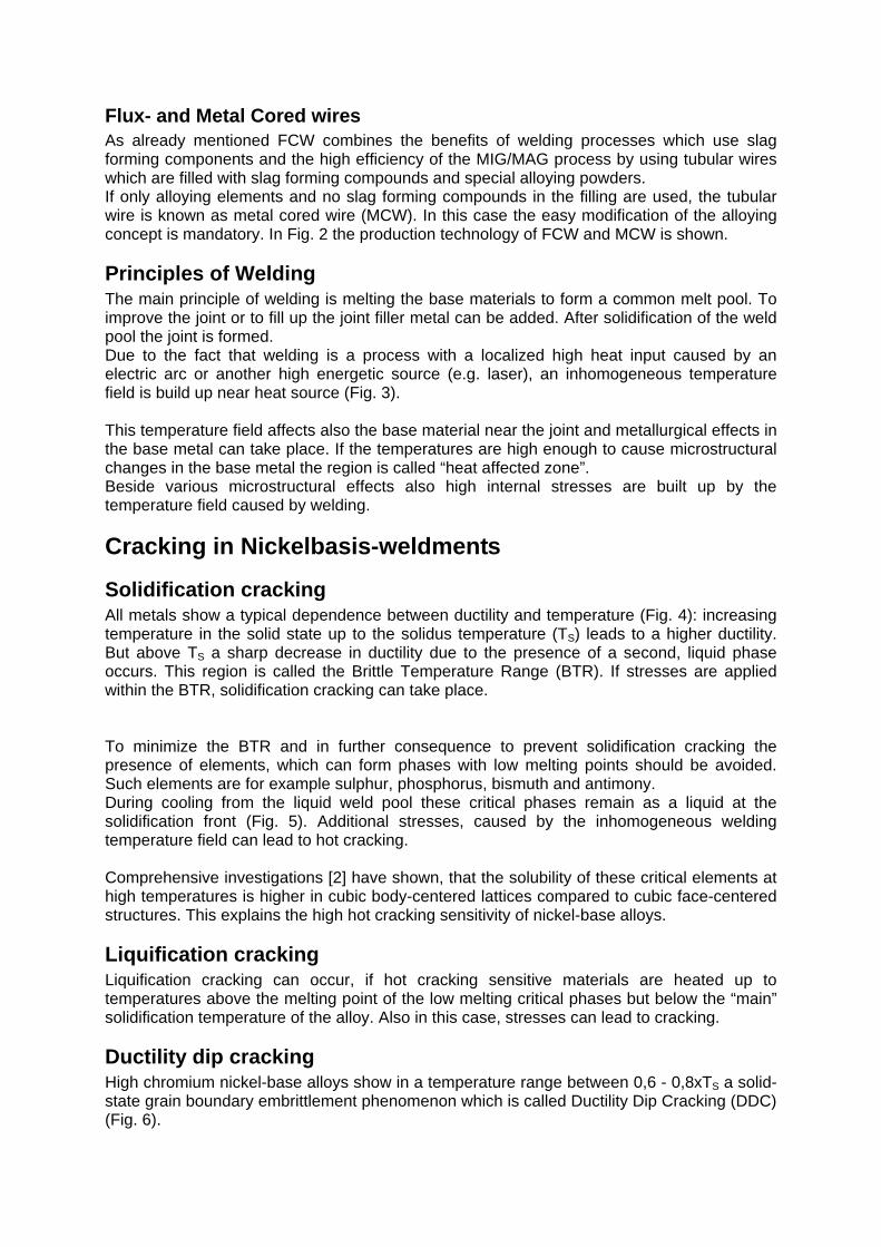
Welding of test specimens To evaluate the mechanical properties and the hot cracking susceptibility all weld metal test specimens (AWM) and plate deposits (PD) were established (Fig. 13) [7]. The making of all weld metal specimen is exact defined in the European standard EN 1579-1. In principle it can be seen as an approx. 20 cm long joint with an approx. 20 mm broad and 20mm high gap. Both sides of the gap have the same chemical composition as the filler

metal to prevent dilution effects. In practical use this is achieved by buffering the plates which are used for establishing the joint with the same filler material. This procedure guarantees test specimen which consist of almost “pure” weld metal. Plate deposits are a kind of multilayer cladding. To create samples of pure weld metal it must be secured, that the first two overlays are not taken into account by preparing the samples. To establish a more or less 20 cm long bar with a rectangular 20mmx25mm cross section copper moulds are used. With these two procedures macro-sized specimen for determination of chemical analysis, hot cracking sensitivity and mechanical properties can be established. Nevertheless it must be taken into account that the distribution of the internal stresses within the samples is completely different: In case of all weld metal sample preparation free shrinkage of the plates is possible; internal stresses caused by the welding process are reduced by plastic deformation of the already existing weld. In contrast plastic deformation is hindered in case of plate deposits. This leads to a much higher level of internal stresses within the specimen.
Tensile properties In longitudinal direction of the all weld and the plate deposit test specimen tensile test samples were worked out and tested using a tensile testing machine. In Fig. 14 and Fig. 15 the results of the tensile testing is shown. The beneficial effect of Niobium addition can clearly be seen. Increasing Niobium content increases fracture elongation and tensile strength. In case of flux-cored weld metal (Fig. 15) it must be taken into account, that also slag systems have an additional influence on the mechanical properties. Commercial available flux-cored wires have in general different slag systems – more basic systems with better mechanical properties, but worse welding properties or rutile systems with superior welding characteristics but lower mechanical properties. Beside alloying concept and slag system also the heat input seams to have an influence on the mechanical properties as it can be seen in Fig. 15 for FCW 18. After the tensile testing the broken specimens were visually inspected. Beside the main fracture more or less minor cracks were found on the surface of the broken test specimen. Due to their appearance they were called “hook cracks” (Fig. 16). The formation of these hook crack can be explained by defects which already exist in the tensile test specimen before testing. By applying the tensile stresses these defects get bigger a will be opened so that they easily can be seen on the surface. In case of nickelbase-alloys such defects are often small hot cracks, especially ductily dip cracks (DDC). These Hook cracks on the broken tensile test specimen can be counted and related to results of the tensile test. A clear correlation between the Hook cracks and the reduction of area can be found for metal cored filler metal (Fig. 17). In Fig. 17 it can also be seen, that in case of the plate deposit (PD) always more Hook cracks were detected compared to the all weld metal specimen. And bringing together with the actual Niobium content of the weld metal, there is also a correlation regarding the Hook cracks: the more Niobium, the less Hook cracks and the higher the reduction of area. In principal same results can also be found for flux-cored filler metal but it must be mentioned that there´s an additional significant influence of the type and basicity of the slag on the number of Hook cracks and reduction of area. In Fig. 18 fractographs of broken tensile test specimens of all weld metal flux-cored wires with different Niobium contents are shown. Beside oxides increasing amounts of small NbC with increasing Nb in the weldmetal can be found. Also a positive influence of Niobium on the grain size appears.

Toughness properties Beside tensile testing also ISO-V toughness testing at -196°C was done. As it can be seen from the results, in case of metal-cored wires Niobium-contents above approx. 2% decrease the toughness of the weld metal. In case of flux-cored wires similar effects could not be detected (Fig. 19). Beside Niobium also Carbon has an influence on the toughness properties: a higher Carbon content leads to lower toughness values compared to weld metal with lower carbon.
Hot cracking sensitivity To determine the hot cracking sensitivity PVR-testing was done on different all weld metal samples established by MMA-, FCW- and solid wire-welding. During testing the specimens were remelted using TIG with a heat input of 6,8kJ/cm. The results show, that Ductility Dip Cracking (DDC), Liquidation Cracking (LC) and the 1st Micro-Solidification Crack (1st Micro-SC) appear at almost the same critical elongation speed (CES). In comparison Solidification Cracking (SC) occurs at higher CES (Fig. 20). In the tests all weld metal of solid wire welding shows a higher hot cracking resistance; fillers with slag systems have nearly the same, but slightly lower CES. Compared to the all weld metal the base metal has the lowest hot cracking sensitivity [7].
Conclusions This investigation has clearly shown, that Niobium is improving the hot cracking resistance of nickel-base filler metals of type NiCr15 and NiCr20. The formation of Niobium carbides plays thereby an important role which cause finer subgrain structures and carbides formation at grain boundaries which improves ductility and lowering the hot crack susceptibility, especially ductility dip cracking. The optimum Niobium content was found to be around 2 - 2,5%. Higher Niobium contents decrease toughness and promote solidification cracking. This investigation also pointed out a lower hot cracking resistance of the filler metals compared to the base metal caused by higher amounts of critical hot-cracking-promoting elements in the weld metal. Comparing different filler metals, the solid wire welding shows the best behaviour, but it must be stated that the welding of the other welding processes exhibits a better performance. But Nickel-base flux-cored wires with optimised slag systems show the best welding behaviour, highest efficiency at acceptable hot cracking susceptibility.
Acknowledgment The authors thank Niobium Company and the Materials Center Leoben (Kplus program of the Austrian government) for financing this investigation and Prof. Herold, Mrs.Streitenberger and Mr. Pchennikov from the Institute of Joining and Beam Technology at TU Magdeburg for performing and evaluation of the PVR-tests. At least a special thank to the senior welding metallurgists Mr. Tösch from Böhler Schweißtechnik Austria and Mr. Heinemann, UTP-Schweißmaterial for their helpful advices.
Literature [1] European Welding Association (EWA); June 2001 [2] E. Folkhard et al.: „Welding metallugry of Stainless Steels”, Springer Verlag, Wien,
1988 [3] J. Lippold: “Further Investigations of Ductility-Dip Cracking in High Chromium, Ni-base
Filler Metals FM52 and FM52M”; IIW-Doc. II-C 326-06 (2006)

[4] E. Folkhard et al: „Der PVR-Test, ein neues Verfahren zur Ermittlung der Rißsicherheit von Schweißwerkstoffen mit hoher quantitativer Aussagekraft“; Sonderdruck aus Jubiläumsschrift "50 Jahre BÖHLER-Schweißtechnik". (Nov. 1977)
[5] G. Rabensteiner, J. Tösch, H. Schabereiter: „Hot Cracking Problems in Different Fully Austenitic Weld Metals“; Welding Journal, (Jan. 1983)
[6] T. Kobayashi et al.: Hot Cracking Susceptibility Evaluation of Austenitic Stainless Steel Weld Metals. The Japan Welding Engineering Society, IIW Doc. II-1068-86/IX-1395-86 (1986)
[7] R. Vallant, H. Cerjak: “Investigation on the mechanical values and the hot crack susceptibility of Ni-base weld metals type 70/20 and 70/15 of different Nb contents”; IIW Doc. II-1535-04 (2004)
Fig. 1: Market share of welding consumables in Europe (1975-2000) [1]
Fig. 2: Production of Flux-cored wires

Fig. 3: Temperature field of a welding cycle
Fig. 4: Dependence between ductility and temperature [3]
Fig. 5: Solidification front of a weldment [3]

Fig. 6: Appearance of Ductility Dip [3]
Fig. 7: Mechanism of DDC [3]
Fig. 8: PVR-test equipment

Fig. 9: principle of PVR-testing
Fig. 10: Surface of PVR-test specimen with different kinds of detected hot cracks [7]

Fig. 11: Standardized chemical composition of various filler metals of type 70/15 and 70/20 [7]
Fig. 12: Variation of Nb and C in the laboratory produced cored wires [7]
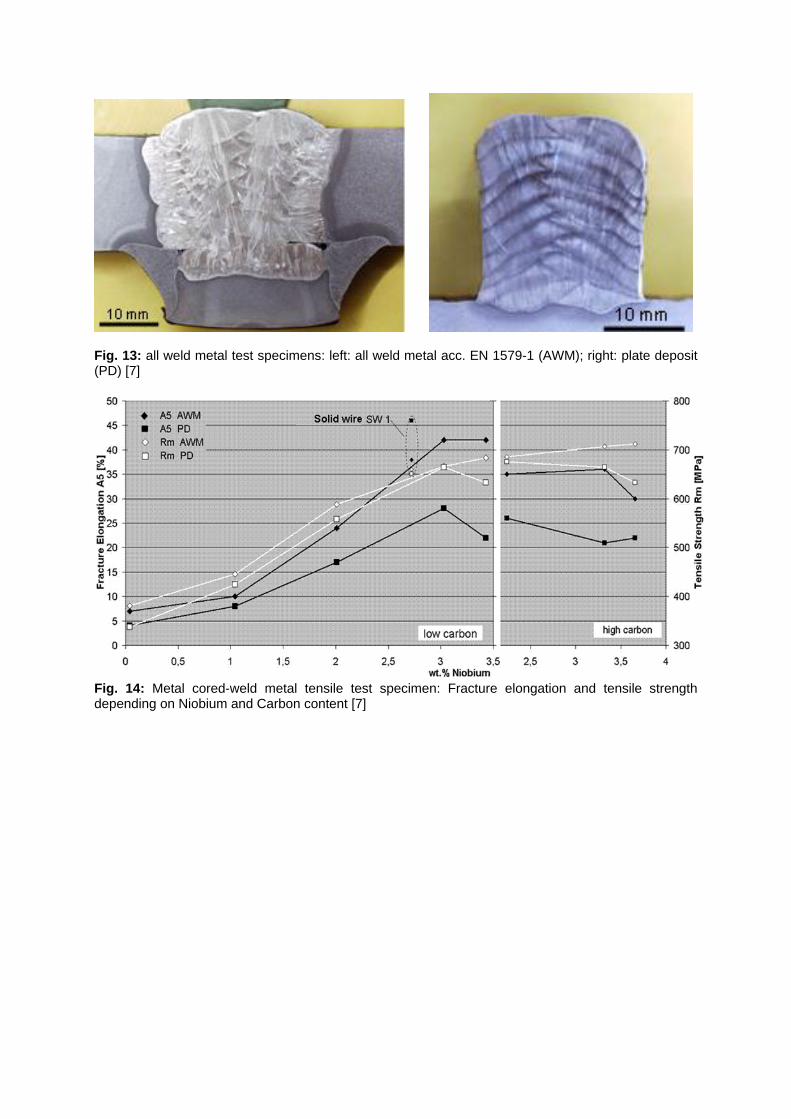
Fig. 13: all weld metal test specimens: left: all weld metal acc. EN 1579-1 (AWM); right: plate deposit (PD) [7]
Fig. 14: Metal cored-weld metal tensile test specimen: Fracture elongation and tensile strength depending on Niobium and Carbon content [7]

Fig. 15: Flux cored-weld metal tensile test specimen: Fracture elongation and tensile strength depending on Niobium content [7]
Fig. 16: „Hook cracks“ on the surface of a broken tensile test specimen [7]
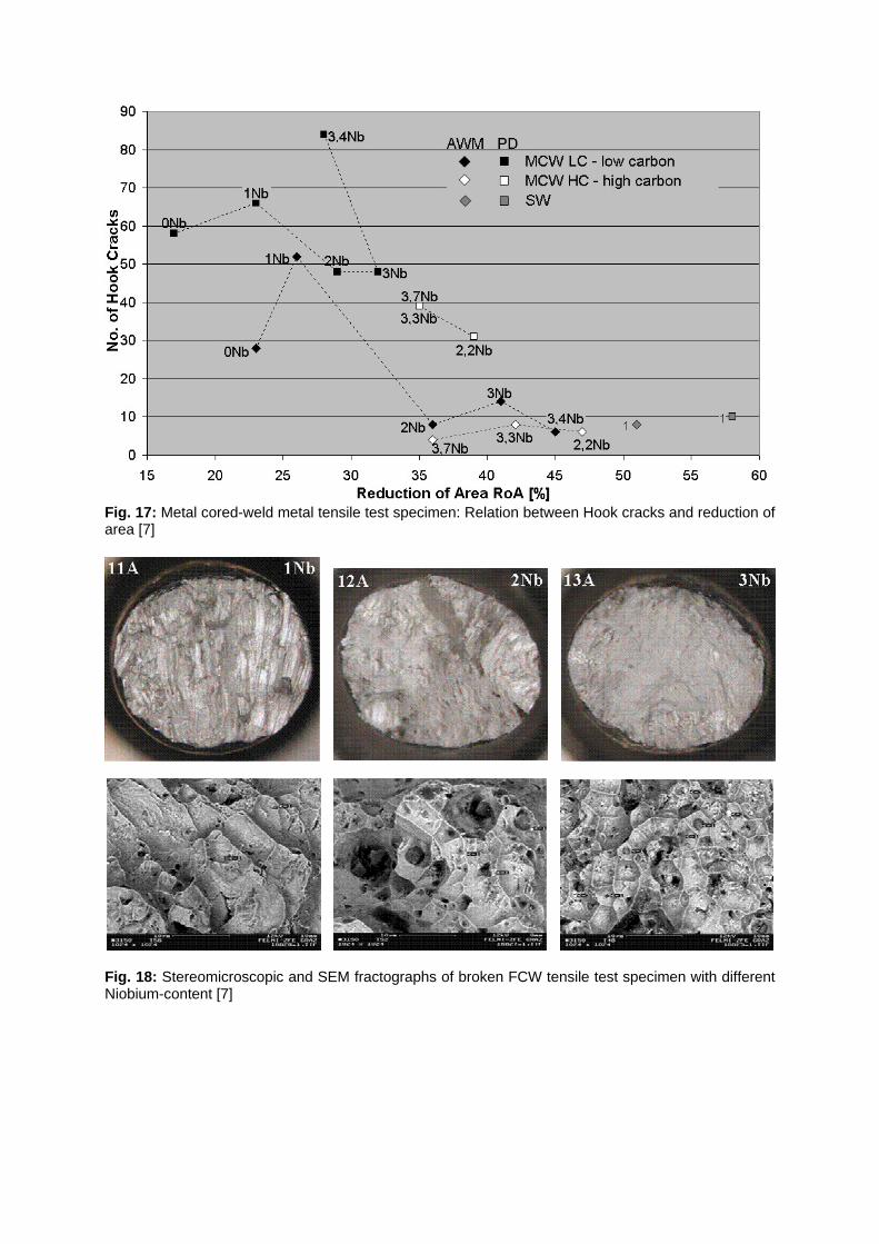
Fig. 17: Metal cored-weld metal tensile test specimen: Relation between Hook cracks and reduction of area [7]
Fig. 18: Stereomicroscopic and SEM fractographs of broken FCW tensile test specimen with different Niobium-content [7]

0
20
40
60
80
100
120
140
160
0 0,5 1 1,5 2 2,5 3 3,5 4
wt % Niobium
Av
(-196
°C) [
J]
MCW (C: 0,05%)MCW (C: 0,1%)FCW (C: 0,05%)
Fig. 19: Toughness at -196°C depending on Niobium and Carbon content
Fig. 20: PVR-test results: all weld metal of MMA, FCW and solid wire compared to base metal TIG –remelted (6,8kJ/cm)