influence of electron-electron collisions on electron energy
TRANSCRIPT

INFLUENCE OF ELECTRON-ELECTRON COLLISIONS ON ELECTRON ENERGY DISTRIBUTIONS AND
TRANSPORT IN INDUCTIVELY COUPLED PLASMAS*
Alex V. Vasenkov and Mark J. KushnerUniversity of Illinois
Department of Electrical and Computer EngineeringUrbana, IL 61801
E-mail: [email protected]@uiuc.edu
URL: http://uigelz.ece.uiuc.edu
May 2002
*Work supported by CFD Research Corp., NSF,Applied Materials, Inc. and the SRC

AGENDA
• Modeling of non-local electron kinetics in ICPs
• Description of the model
• Validation of the model for ICPs in Ar
• Stochastic heating in ICPs
• Modeling of electron transport for ICPs in CF4
• Summary
University of IllinoisOptical and Discharge PhysicsICOPS-2002-02

ELECTRON KINETICS IN ICPs• The trend towards using high-plasma density (>1011cm-3), low gas
pressure (< 10s mTorr) sources in materials processing has resulted in renewed interest in electron kinetics in ICPs.
• Owing to the electron energy distribution (EED) is generally non-Maxwellian, a kinetic approach is required for modeling ICPs.
PUMP PORT
DOME
GAS INJECTORS
BULK PLASMA
WAFER
30 30 0 RADIUS (cm)
HEI
GH
T (c
m)
0
26
sCOILS
s
rf BIASED SUBSTRATE
SOLENOID
POWER SUPPLY
POWER SUPPLY
University of IllinoisOptical and Discharge PhysicsICOPS-2002-03

ELECTRON KINETICS IN ICPs
• One of the basic problems in the kinetic simulation of ICPs is the consideration of e-e collisions, which significantly influence the thermal motion of electrons.
• There are at least three approaches to resolve e-e collisions:
(i) Particle-in-cell simulations (Nanbu et al, 1997, 2000)
(ii) Direct solution of Boltzmann’s equation (Kolobov et al, 1997)
(iii) Electron Monte Carlo simulation (Weng et al, 1990)
University of IllinoisOptical and Discharge PhysicsICOPS-2002-04

HYBRID PLASMA EQUIPMENT MODEL
MATCH BOX-COIL CIRCUIT MODEL
ELECTRO- MAGNETICS
FREQUENCY DOMAIN
ELECTRO-MAGNETICS
FDTD
MAGNETO- STATICS MODULE
ELECTRONMONTE CARLO
SIMULATION
ELECTRONBEAM MODULE
ELECTRON ENERGY
EQUATION
BOLTZMANN MODULE
NON-COLLISIONAL
HEATING
ON-THE-FLY FREQUENCY
DOMAIN EXTERNALCIRCUITMODULE
PLASMACHEMISTRY
MONTE CARLOSIMULATION
MESO-SCALEMODULE
SURFACECHEMISTRY
MODULE
CONTINUITY
MOMENTUM
ENERGY
SHEATH MODULE
LONG MEANFREE PATH
(MONTE CARLO)
SIMPLE CIRCUIT MODULE
POISSON ELECTRO- STATICS
AMBIPOLAR ELECTRO- STATICS
SPUTTER MODULE
E(r,θ,z,φ)
B(r,θ,z,φ)
B(r,z)
S(r,z,φ)
Te(r,z,φ)
µ(r,z,φ)
Es(r,z,φ) N(r,z)
σ(r,z)
V(rf),V(dc)
Φ(r,z,φ)
Φ(r,z,φ)
s(r,z)
Es(r,z,φ)
S(r,z,φ)
J(r,z,φ)ID(coils)
MONTE CARLO FEATUREPROFILE MODEL
IAD(r,z) IED(r,z)
VPEM: SENSORS, CONTROLLERS, ACTUATORS
University of IllinoisOptical and Discharge PhysicsICOPS-2002-05

ALGORITHM FOR E-E COLLISIONS
• The basis of the algorithm for e-e collisions is “particle-mesh”.
• Statistics on the EEDs are collected according to spatial location.
• An energy of collision target is randomly selected from the EED at this location
= ∑i
iiiitrtrtrtr ∆t∆εε)f(ε∆t/∆εε)f(ε)P(ε
• Since, the number of energy bins is usually large (400-500), quick lookup techniques are used for the energy of collision targets.
• In this technique the lth cumulative probability is determined from
∑∑≤≤−
=i
iε'εε'
jl )P(ε)/P(εΠljl 1
University of IllinoisOptical and Discharge PhysicsICOPS-2002-06
ALGORITHM FOR E-E COLLISIONS
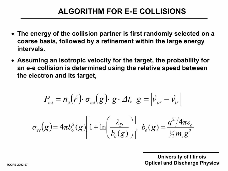
• The energy of the collision partner is first randomly selected on a coarse basis, followed by a refinement within the large energy intervals.
• Assuming an isotropic velocity for the target, the probability for an e-e collision is determined using the relative speed between the electron and its target,
( ) ( ) trpreeeee vvg∆t,ggσrnP rrr−=⋅⋅⋅=
( ) 22
1
22 4)(
)(ln1)(4
gmπεqgb,
gbλgπbgσ
e
oo
o
Doee =
+=
University of IllinoisOptical and Discharge PhysicsICOPS-2002-07

ALGORITHM FOR E-E COLLISIONS
)πr(r| g|'g
)πr(r|g|', g|rg|'g
y
xz
22
1
22
11
2sin1
2cos1
−=
−=±=r
rr
• If a collision occurs, then a post collision relative velocity is randomly determined as,
• Finally, the velocity of the pseudo-electron is updated with,
)vv(.v ' g.vv prtrRRfrrrrrr
+=+= 5050
• The change in velocity of the collision partner is disregarded; e-e collisions are treated as collisions between pseudo-electrons and energy resolved electron fluid.
• The consequences of e-e collisions on the targets are obtained by continuously updating the stored EEDs.
University of IllinoisOptical and Discharge PhysicsICOPS-2002-08

ICP CELL FOR VALIDATION AND INVESTIGATION
ICOPS-2002-09
• Experiments by Godyak et al (1998) are used for validation.
• The experimental cell is an ICP reactor with a Faraday shield to minimize capacitive coupling.
University of IllinoisOptical and Discharge Physics

University of IllinoisOptical and Discharge Physics
ELECTRON DENSITY FOR STANDARD CASE
ICOPS-2002-10
)3cm10(10 [e] −
• Electron density is largest in the middle of reactor where the electric potential is maximum.
• Ar, 10 mTorr, 100 W, 6.78 MHz

IONIZATION SOURCE FOR STANDARD CASE
University of IllinoisOptical and Discharge PhysicsICOPS-2002-11
)1s3cm14(10 iS −−
• The ionization source reaches a maximum at the edge of the classical skin depth where the amplitude of the electromagnetic field decays to 1/e of its edge value.
• Ar, 10 mTorr, 100 W, 6.78 MHz

University of IllinoisOptical and Discharge Physics
Te FOR STANDARD CASE: Ar, 10 mTorr, 100 W, 6.78 MHz
ICOPS-2002-12
• The first major peak occurs in the skin depth owing to collisionless electron heating by the large electric field.
• The second minor peak corresponds to the position where the electron density reaches the maximum.
(eV) eT

University of IllinoisOptical and Discharge PhysicsICOPS-2002-13
• The ion temperature reaches a maximum near the walls where ions gain energy due to acceleration in the presheath.
• In the middle of reactor the ion temperature is lower owing to thermalization with neutral species.
Ti FOR STANDARD CASE: Ar, 10 mTorr, 100 W, 6.78 MHz
(eV) iT

• The maximum of electron density is displaced from the center due to the axial location of the source function.
• The high thermal conductivity and redistribution of energy by e-e collisions produce nearly uniform electron temperatures.
100
101
102
2
3
4
5
6
7
0 2 4 6 8 10
n e (1010
cm-3
)
Height (cm)
Te (eV)
ne
Te
symbols, Exp., Godyak (1998)curves, Model
Te and ne ALONG THE CENTERLINE OF THE REACTOR
• Ar, 10 mTorr, 100 W, 6.78 MHz, r=0
University of IllinoisOptical and Discharge PhysicsICOPS-2002-14

EFFECT OF E-E COLLISIONS ON THE EEDs
• Low energy electrons want to “pool” at the peak in plasma potential in the center of the reactor.
• When including e-e collisions, the fraction of low-energy electrons is smaller due to energy transfer between low-energy and high-energy electrons.
ICOPS-2002-15
10-2
10-1
100
101
without e-e collisions
with e-e collisions
EED
(eV-3
/2)
r=1 cmz=3 cm
10-2
10-1
100
0 2 4 6 8 10Energy (eV)
EED
(eV-3
/2) without e-e collisions
with e-e collisions
r=4 cmz=3 cm
• Ar, 10 mTorr, 100 W, 6.78 MHz
University of IllinoisOptical and Discharge Physics
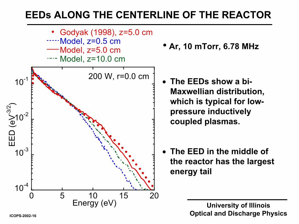
EEDs ALONG THE CENTERLINE OF THE REACTOR
• The EEDs show a bi-Maxwellian distribution, which is typical for low-pressure inductively coupled plasmas.
• The EED in the middle of the reactor has the largest energy tail
10-4
10-3
10-2
10-1
0 5 10 15 20
Godyak (1998), z=5.0 cmModel, z=0.5 cmModel, z=5.0 cmModel, z=10.0 cm
Energy (eV)
EED
(eV-3
/2)
200 W, r=0.0 cm
• Ar, 10 mTorr, 6.78 MHz
University of IllinoisOptical and Discharge PhysicsICOPS-2002-16

EEDs ALONG THE CENTERLINE OF THE REACTOR
ICOPS-2002-17
• In the skin layer the EED is depleted at low energies.
• EEDs near the peak plasma potential (z = 5.0 cm) have larger a low energy component.
10-4
10-3
10-2
10-1
Godyak (1998), z=5.0 cmModel, z=0.5 cmModel, z=5.0 cmModel, z=10.0 cm
0 5 10 15 20
EED
(eV-3
/2)
50 W, r=0.0 cm
Energy (eV)
• Ar, 10 mTorr, 6.78 MHz
University of IllinoisOptical and Discharge Physics

University of IllinoisOptical and Discharge Physics
EEDs IN SKIN LAYER AND BULK PLASMA
ICOPS-2002-18

EFFECT OF PRESSURE ON THE EEDs
ICOPS-2002-19
10-6
10-5
10-4
10-3
10-2
10-1
z=0.5 cmz=5.0 cm
0 5 10 15 20 25 30
EED
(eV-3
/2)
1 mTorr
10-6
10-5
10-4
10-3
10-2
10-1
z=0.5 cmz=5.0 cmz=10.0 cm
0 5 10 15 20 25 30
EED
(eV-3
/2)
30 mTorr
Energy (eV)
• At 1 mTorr the EEDs are dominated by collisionless heating and by non-linearLorentz forces, which provide an axial acceleration.
• The EEDs at 30 mTorr are in a collisional regime and therefore they resemble aDruyvesteyn distribution.
• Ar, 100 W, 6.78 MHz
z=10.0 cm
University of IllinoisOptical and Discharge Physics

EXPERIMENTAL CELL FOR INVESTIGATION OF ICPs IN CF4
• Modeling of ICPs in CF4 involves complex surface and gas-phase chemistry.
• It is particularly challenging due to only limited data is available for electron–CFx and CFx-CFx radical collisions.
• Experiments by Singh, Coburn, and Graves [J. Vac. Sci. Technol. A v. 19, 718 (2001)] are used for a comparison.
University of IllinoisOptical and Discharge PhysicsICOPS-2002-20
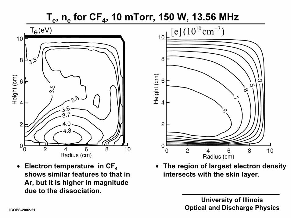
Te, ne for CF4, 10 mTorr, 150 W, 13.56 MHz)cm(10 [e] 310 −
• The region of largest electron density intersects with the skin layer.
• Electron temperature in CF4shows similar features to that in Ar, but it is higher in magnitude due to the dissociation.
(eV)eT
University of IllinoisOptical and Discharge PhysicsICOPS-2002-21

EXPERIMENTAL AND COMPUTED EEDs
10-3
10-2
10-1
0 3 6 9 12 15
Exp., Singh et al (2001) Model
EED
(eV-3
/2)
Energy (eV)
n e= 5 1010 cm-3 n
e= 7 1010 cm-3
• Model yields the same slope as experiment.
• A peak in the computed EED occurs at about 3 eV.
• CF4, 10 mTorr, 150 W, 13.56 MHz, r=0, z=7.6 cm
University of IllinoisOptical and Discharge PhysicsICOPS-2002-22

• EED is well represented by a Maxwellian distribution in the sheath
• In the bulk plasma the position of the peak shifts to higher energies approaching the skin layer.
• EED in the skin layer shows usual bi-Maxwellian features.
10-2
10-1
0 2 4 6 8 10
Model, z=10 cmModel, z=9 cmModel, z=7 cmModel, z=5 cm
EED
(eV-3
/2)
Energy (eV)
r=0.5 cm
COMPUTED EDDs IN CF4 AT DIFFERENT HEIGHTS
• CF4, 10 mTorr, 150 W, 13.56 MHz
Model, z=1 cm
University of IllinoisOptical and Discharge PhysicsICOPS-2002-23

10-2
10-1
Model, r=0 cmModel, r=1 cmModel, r=2 cmModel, r=5 cmModel, r=9 cm
0 2 4 6 8 10
z=7.6 cm
EED
(eV-3
/2)
Energy (eV)
• CF4 , 10 mTorr, 150 W, 13.56 MHz
• A peak occurs in the EEDs for radii < 2 cm.
• This peak is formed due to the flux of electrons which collisionlessly propagates from the coils to the opposite wall.
• This flux is formed as a result of interaction between the skin layer and the region of largest electron density.
EDDs IN CF4 AT DIFFERENT RADII
University of IllinoisOptical and Discharge PhysicsICOPS-2002-24

EXPERIMENTAL AND COMPUTED EEDs
• The energy exchange between electrons is eliminated by excluding e-e collisions.
• RF fields do not propagate beyond the normal skin layer when the cold plasma approximation is used.
• In both these cases the thermal electron motion is significantly affected.
• CF4, 3 mTorr, 150 W, 13.56 MHz
10-3
10-2
10-1
0 3 6 9 12 15
Exp., Singh et al (2001)ModelModel, without e-e collisionsModel, cold plasma
EED
(eV-3
/2)
Energy (eV)
Exp., n e
= 5 1010 cm-3
Model, n e
= 7 1010 cm-3
University of IllinoisOptical and Discharge PhysicsICOPS-2002-25

SUMMARY
• We present a new method for modeling e-e collisions in which Coulomb collisions are treated using a test particle approach and, so can be readily included in Monte Carlo simulations of low-pressure and high-density plasma systems.
• The method was validated by comparing calculated and measured electron densities, temperatures, and electron distributions in inductively coupled argon plasma.
• The EEDs are significantly depleted at low energies in regimes dominated by non-collisional heating.
• A maximum in the computed EEDs in CF4 depends on the thermal motion of electrons.
University of IllinoisOptical and Discharge PhysicsICOPS-2002-26

University of IllinoisOptical and Discharge Physics
NET CURRENT FOR CF4 , 10 mTorr, 150 W, 13.56 MHz
ICOPS-2002-a1