influence of column shear failure on pushover based
TRANSCRIPT
This is a repository copy of Influence of column shear failure on pushover based assessment of masonry infilled reinforced concrete framed structures: A case study.
White Rose Research Online URL for this paper:http://eprints.whiterose.ac.uk/144588/
Version: Accepted Version
Article:
Cavaleri, L, Di Trapani, F, Asteris, PG et al. (1 more author) (2017) Influence of column shear failure on pushover based assessment of masonry infilled reinforced concrete framed structures: A case study. Soil Dynamics and Earthquake Engineering, 100. pp. 98-112. ISSN 0267-7261
https://doi.org/10.1016/j.soildyn.2017.05.032
© 2017 Elsevier Ltd. This manuscript version is made available under the CC-BY-NC-ND 4.0 license http://creativecommons.org/licenses/by-nc-nd/4.0/.
[email protected]://eprints.whiterose.ac.uk/
Reuse
This article is distributed under the terms of the Creative Commons Attribution-NonCommercial-NoDerivs (CC BY-NC-ND) licence. This licence only allows you to download this work and share it with others as long as you credit the authors, but you can’t change the article in any way or use it commercially. More information and the full terms of the licence here: https://creativecommons.org/licenses/
Takedown
If you consider content in White Rose Research Online to be in breach of UK law, please notify us by emailing [email protected] including the URL of the record and the reason for the withdrawal request.
1
Influence of column shear failure on pushover based assessment of masonry 1
infilled reinforced concrete framed structures: a case study 2
Liborio Cavaleri (Corresponding Author) 3
Department of Civil, Environmental, Aerospace and Materials Engineering (DICAM), University of Palermo, Viale delle Scienze, 4
90128, Palermo, Italy 5
Email: [email protected] 6
Fabio Di Trapani 7
Department of Civil, Environmental, Aerospace and Materials Engineering (DICAM), University of Palermo, Viale delle Scienze, 8
90128, Palermo, Italy 9
Email: [email protected] 10
Panagiotis G. Asteris 11
Computational Mechanics Laboratory, School of Pedagogical and Technological Education, Heraklion, GR 14121, Athens, Greece. 12
Email: [email protected] 13
Vasilis Sarhosis 14
School of Civil Engineering and Geosciences, Newcastle University, Newcastle upon Tyne, NE1 7RU, UK 15
Email: [email protected] 16
17
Abstract: Structural frames, constructed either of steel or reinforced concrete (RC), are often infilled with 18
masonry panels. However, during the analysis of the structural frames, it has become common practice to 19
disregard the existence of infills because of the complexity in modeling. This omission should not be allowed 20
because the two contributions (of infills and of frames) complement each other in providing a so different 21
structural system. The use of different modeling assumptions significantly affects the capacity as well as the 22
inelastic demand and safety assessment. In specific, the adoption of equivalent diagonal pin-jointed struts 23
leaves open the problem of the evaluation of the additional shear on columns and consequently of the choice 24
of a proper eccentricity for the diagonal struts. In this context, this paper presents the results of a real case 25
study. The seismic performance of the RC structure of a school is evaluated by using concentric equivalent 26
struts for modeling infills and the level of the additional shear on the columns is fixed as a rate of the axial 27
force on them in agreement to a strong correlation obtained after a numerical experimentation. Hence, the 28
applicability of the correlation mentioned before is shown and the form in which the results can be provided 29
is presented. The characteristics of the new approach, first time applied to a real case, are highlighted by a 30
comparison between the performance obtainable with different modeling detail levels of the infills. Through 31
the paper, it is proved that the simplified evaluation of the additional shear demand produced by infills just 32
for the base columns is sufficient to warn that a simplified model disregarding infills or based on the use of 33
concentric struts for the infills may considerably overestimate the structural capacity. Further, by the study of 34
a real case, the paper provides an overview of the models developed by the authors to obtain the capacity of 35
reinforced concrete framed structure for the practical applications. 36

2
Keywords: Masonry infill wall panels; RC frames; pushover analysis; local shear action. 37
1. Introduction 38
Building frames are usually infilled with masonry walls as a natural consequence of the necessity of 39
separating the internal spaces from the external environment. Although masonry infills are not 40
designed as structural elements per se, their interaction with the RC frames significantly influences 41
the structural behavior of a building in terms of stiffness, strength and overall ductility . During an 42
earthquake, infill walls may increase or not the lateral earthquake load resistance significantly, may 43
undergo a premature damage, developing diagonal tension and compression failures or out-of-plane 44
failures. The degree of lateral load resistance depends on the amount of masonry infill walls used 45
and their direction and position within the structure. Negative effects are often associated with 46
irregularities in the distribution of infills in plan and elevation. This stiffness asymmetry may cause 47
torsion which magnifies the lateral displacement response of the structure while the abrupt change 48
in stiffness in elevation may cause “soft story” mechanisms (Figure 1). Besides these mechanisms, 49
which involve the overall structural response, the infill – frame interaction occurs also locally. 50
Infills, because of their high stiffness, attract a large amount of lateral force, that is transferred to the 51
surrounding frames in the proximity of the ends of RC beams and columns as an additional shear 52
force. The further shear demand may be not supported by these regions if adequate shear 53
reinforcement is not present, and may have as a consequence a brittle failure localized in most of 54
the cases in joints or the ends of columns (Figure 2). Due to the design and methodological 55
complexity of masonry infilled RC framed structures, the numerical analysis for their structural 56
assessment is necessary. 57
Over the last three decades, different computational modeling strategies have been developed 58
aiming to address different levels of complexity. Among the modeling strategies, the most common 59
one is that of the macro-modeling approach, which consists of the replacement of the infill by an 60
equivalent pinned strut made of the same material and having the same thickness as the infill panel. 61

3
The macro-modelling approach is mainly used for the assessment of the stiffening and 62
strengthening effects in non-linear static or dynamic analyses (Holmes, 1961; Stafford Smith , 63
1966; Stafford Smith & Carter C, 1969, Mainstone, 1971,1974; Papia, Cavaleri, & Fossetti, 2003; 64
Saneinejad, & Hobbs, 1995; Asteris, Cavaleri L, Di Trapani F, & Sarhosis, 2015). In this 65
approach, the selection of a constitutive law for the strut able to represent accurately the mechanical 66
behavior of the masonry wall is essential. Available models for the definition of a force – 67
displacement curve for the strut are based on preliminary hypotheses about the modality of failure 68
of the infill – frame system (Bertoldi, Decanini, & Gavarini, 1993; Panagiotakos, & Fardis, 1996; 69
Žarnić R, & Gostič, 1997). In addition, for the assessment of the dynamic seismic response of the 70
masonry infilled RC framed structures, several experimental studies (e.g. Klingner, & Bertero, 71
1978; Doudoumis, & Mitsopoulou, 1986; Cavaleri, Fossetti & Papia M, 2005; Kakaletsis, & 72
Karayannis, 2009; Cavaleri , Di Trapani, Macaluso, Papia, & Colajanni, 2014; Cavaleri, & Di 73
Trapani, 2014; Lima et al., 2014; Madan et al., 2015; Himaja et al., 2015) have been undertaken and 74
simplified modeling rules have been identified in order to predict the hysteretic behavior of the 75
structure. A radically different approach makes use of FE micro-models to simulate the mechanical 76
behavior of both infills and RC frames (e.g. Mehrabi, & Shing, 1997; Shing, & Mehrabi, 2002; 77
Asteris, 2003, Koutromanos, Stavridis, Shing, & Willam, 2011; Koutromanos, & Shing, 2012). In 78
this case, infills are modeled generally by 2-D finite elements. maintaining the geometry as it is. 79
The surrounding frame is modeled by beam elements and ad hoc finite elements are used for the 80
interface frame-infill able to simulate the detachment occurring between frame and infill during the 81
application of a lateral load. This choice surely represents the most accurate solution, being the 82
closest to the actual physical system under investigation. However, any analysis with this level of 83
refinement requires a large computational effort. Focusing the attention on macro-modeling 84
approach it constitutes an attractive solution, despite the fact that a conspicuous number of 85
uncertainties affect the identification of the equivalent geometrical and mechanical properties be 86

4
attributed to the struts. Recent studies (e.g. Dolšek, & Fajfar, 2008; Uva, Porco, & Fiore, 2012) 87
demonstrate that the resulting structural response (mainly determined by means of static pushover 88
analyses) may be sensitive to the imprecise or incorrect identification of some key parameters such 89
as equivalent strut width or panel strength. The major difficulties regarding the identification of 90
governing parameters are mainly related to: 91
uncertainty in the identification of mechanical characteristics of existing masonry due to the 92
variability of materials, differences in arrangements techniques and aging; 93
uncertainty in the identification of actual ultimate strength capacity of the masonry wall 94
panel including the influence of vertical loads, panel – frame effective contact lengths and 95
possible failure mechanisms; 96
variability of equivalent properties depending on the aspect ratio of the frame and on infill – 97
frame strength and stiffness ratios; 98
contact issues between the infill and the frame which control the transfer of shear force. 99
Further uncertainties arise when concentric braced macro-models are adopted, configuring the 100
impossibility to predict the additional shear demand at the ends of RC beams and columns due to 101
the local interaction with infills. To circumvent this limit, multiple strut macro-models have been 102
developed (e.g. Crisafulli, 1997; Chrysostomou, & Gergely, 2002; El-Dakhakhni, Elgaaly, & 103
Hamid, 2003). According to these models, the additional shear demand is determined as result of a 104
non-concentric disposition of two or more equivalent struts. However, the calibration of an 105
adequate nonlinear constitutive law, which is needed for each strut, determines new unknowns. An 106
alternative solution has been proposed by Cavaleri L, & Di Trapani (2015) in which the use of 107
concentric single struts is maintained, determining shear demand in critical sections as a rate of the 108
axial load acting on them. A similar approach is used by Celarec and Dolšec (2013) with a different 109
strategy in the estimation of the rate of the axial force in the strut that contributes to the additional 110
shear in the critical frame member sections. Differently from Celerac and Dolšec (2013) that use an 111

5
iterative pushover analysis procedure, the determination of the entity of the axial load transferred as 112
shear to each section is obtained by Cavaleri and Di Trapani (2015) through the use of shear 113
distribution coefficients (found after an extended numerical experimentation on infilled frames with 114
different characteristics) that are analytically correlated to the geometrical and mechanical features 115
of the infill – frame system. A review of the modeling strategies to be adopted to model the infill-116
frame interaction can be found in Di Trapani, Macaluso, Cavaleri, & Papia (2015). As regards to 117
pushover based procedures for the assessment of infilled frames, a number of studies (Dolšek, & 118
Fajfar, 2004; 2005; 2008) have proposed alternatives demand spectra to be used in the N2 method, 119
which however are calibrated on the weak-infill / strong-frame collapse mechanism, neglecting also 120
the potential premature shear failure of the frame. In other cases (e.g. Martinelli et al. 2015) 121
simplified procedures have been proposed to adjust the results deriving from the use of typical 122
demand spectra which are more proper for bare frame systems. The need to accurately assess the 123
seismic behavior and structural capacity of existing buildings is nowadays increasing so that several 124
local governments have required seismic assessment of buildings which have strategic regional 125
roles (hospitals, barracks, city halls) or attract large crowds (schools, universities). Unfortunately, 126
when investigating masonry infilled RC framed structures, the choices made in the identification of 127
the structural models largely affect the outcomes which in many cases are also conflicting. 128
Although in the engineering profession large simplifications are often required to overcome 129
really complex problems, engineers should be aware of the reliability bounds and the limits of the 130
tools they are utilizing, especially when they are called to express themselves on the safety of 131
buildings having a crucial importance in post-earthquake scenarios. Significant questions include 132
the following: What are the different outcomes to expect under the different modeling hypotheses? 133
Which is the reliability of the safety assessments carried out by each of them? For the reasons 134
presented in the previous paragraphs, this paper discusses the results of different possible choices in 135
the identification of framed struts with masonry infills and the relative impact on the resultant 136
6
overall capacity in terms of strength, stiffness, and ductility. The interest is focused on the problem 137
of the evaluation of the additional shear on columns produced by infills that may anticipate the 138
collapse and on how can be solved maintaining the simple approach of substituting infill by a 139
concentric diagonal strut. To this aim a case study is discussed in which, first time, a) the procedure 140
proposed in Cavaleri, & Di Trapani (2015) is experimented, b) which strategy has to be used for its 141
application its applicability is tested and c) a strategy for presenting the results is provided. 142
In order to highlight the approach presented a comparison between the results coming from 143
different assumptions is provided: a) neglecting of infills contribution, b) concentric macro-144
modeling and c) concentric macro-modeling with the prediction of local interaction effects. 145
As a case study an existing three-storey RC building, infilled with hollow clay block masonry wall 146
panels, has been studied. The building serves as a school and has been built in Avezzano (Italy) in 147
the 1950s. The building was recently subjected to a structural quick inspection and assessment of its 148
structural vulnerability due to the high seismicity of the area, as reported in Colajanni, Cucchiara, & 149
Papia (2012). The structural model developed utilized SAP 2000 NL simulating beam elements 150
with lumped plasticity for beams and columns and a pair of diagonal multi-linear plastic links for 151
the equivalents struts. The effect of the differential structural identification is discussed by 152
analyzing the results of the pushover curves obtained by considering the results obtained from 153
different modeling approaches within the framework of the N2 method whose applicability is better 154
explained in Section 4. 155
2. Description of the building and adopted mechanical parameters 156
The building under investigation is an RC framed structure constructed in the 1950s. It is composed 157
of three stories and it is L-shaped. The first two have an area of 520 m2 while the third one has an 158
area of 330 m2. The front face of the building has a span of 40 m. The floors of the building have 159
been constructed as one-way ribbed concrete slabs. Plan views of each level of the building are 160

7
shown in Figure 3. Specimens of steel smooth rebars (everywhere rebars were bounded by end 161
hook) and concrete cores were obtained from the building and tested in the laboratory as per the 162
Italian code D.M. 14/01/2008 (2008). From the experimental testing, it was found that the average 163
value of steel yielding stress (fym) is equal to 300 MPa (Cv=0.015) while the average concrete peak 164
strength (fcm) is 15 MPa (Cv=0.2). Considering the experimental results, for the analysis, an elastic-165
perfectly plastic law was assumed for steel, with Young modulus (Es) equal to 200.000 MPa and an 166
ultimate strain (su) equal to 8%. Taking into account the low transversal reinforcement ratio of 167
concrete elements (stirrups 8 with a 25 cm spacing for beams and columns), and consequently the 168
low level of confinement, the constitutive relationship developed by Hognestad (1951) was adopted 169
to simulate the mechanical behavior of the concrete of the structural elements. The latter is 170
characterized by a parabolic branch up to c0 equal to 0.002 followed by a linear softening branch 171
up to the ultimate strain cu equal to 0.0035, corresponding to a strength reduction of -15%. Also, 172
the Young modulus of concrete (Ecm) was estimated according to the expression provided by the 173
Italian code as 22000 (fcm /10)0.3 and found to be equal to 24830 MPa. Details of reinforcement of 174
beam and columns are reported in Tables 1 and 2. The infill panels were made of clay bricks and 175
were 30 cm thick and 3.40 m high. The infills, made overall with the same masonry, have been 176
classified by four different typologies (T1, T2, T3, T4) according to their aspect ratio (Table 3) and 177
considering the presence of openings. Infills T1, T2, T4 are characterized by openings, further, the 178
label T1 was attributed to the infills having the smallest length while the label T3 and T4 to infills 179
having the highest height. In order to not have too many typologies infills having a length in a fixed 180
length range were considered belonging to the same class. In Table 4 the elastic characteristics 181
(Young modulus Em and rigidity modulus Gm ) of the infill masonry are inserted. The Young 182
modulus was obtained by the correlation available in the Italian code between the strength of 183
masonry fk and its Young modulus (Em= 1000 fk). While the strength fk was obtained by the 184
correlation provided by the Italian code in form of table with the strengths of bricks and mortar. In 185
8
this case, similar characteristics were obtained along the vertical and the horizontal directions for 186
bricks (about 15 Mpa) while for the mortar a mean strength of 10 Mpa was derived, hence the value 187
for Em inserted in Table 4 represents a value to be applied to the two directions above mentioned. 188
The value for Gm was estimated, as proposed by different codes (included MSJC), as 0.4 of Em. 189
Starting from the strength of bricks (15 Mpa) and of mortar (10 Mpa) used for the infills, it was 190
possible the estimation of the shear strength fv0m by using a specific correlation provided by the 191
Italian code in form of table. 192
193
3. Definition of the mechanical nonlinearities 194
3.1 RC beams and columns 195
Beams and columns were modeled by means of lumped plasticity hinges at their ends while the 196
joint panels were considered rigid. A moment – rotation rigid-plastic law was assigned to the 197
hinges. The interaction between axial force and bending moments was taken into account. In 198
details, ultimate and yielding rotations (u and y) were calculated according to the expressions 199
reported by Italian Technical Code (2008) as functions of the respective ultimate and yielding 200
curvatures (u and y). For the columns, strength values (i.e. P-Mx-My) were numerically calculated 201
by means of an ad hoc code. Consistently with the findings described in Campione, Cavaleri, Di 202
Trapani, Macaluso, & Scaduto (2016), the biaxial deformation capacity of the hinges was defined 203
by tracing specific P-u,x-u,y domains, whose 3D surfaces were determined calculating ultimate 204
rotations associated with different axial load levels and bending directions. The relationship 205
between ultimate rotations in biaxial bending (u,x, u,y) and those along principal axes (uo,x, uo,y ) 206
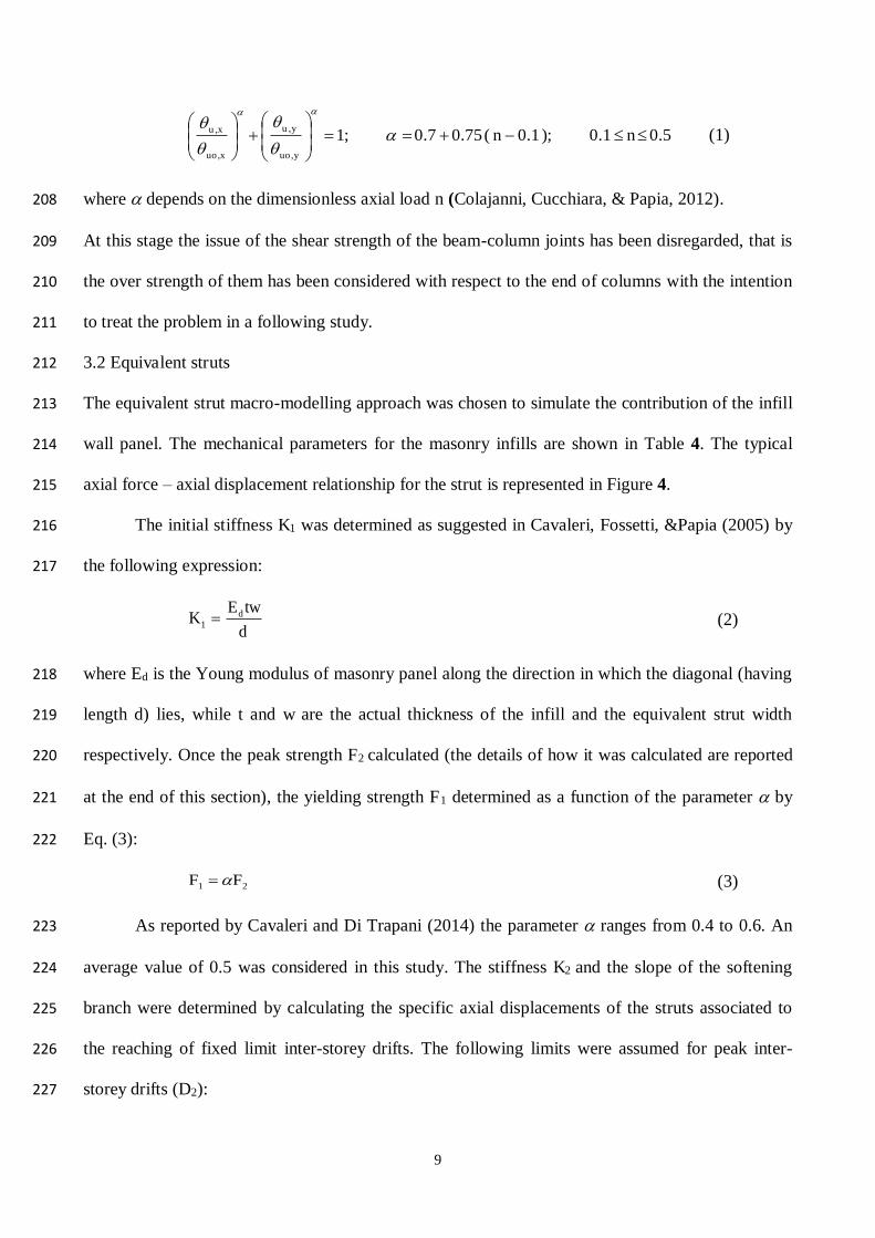
have been described by Eq. (1): 207
9
5.0n1.0);1.0n(75.07.0;1y,uo
y,u
x,uo
x,u
(1)
where depends on the dimensionless axial load n (Colajanni, Cucchiara, & Papia, 2012). 208
At this stage the issue of the shear strength of the beam-column joints has been disregarded, that is 209
the over strength of them has been considered with respect to the end of columns with the intention 210
to treat the problem in a following study. 211
3.2 Equivalent struts 212
The equivalent strut macro-modelling approach was chosen to simulate the contribution of the infill 213
wall panel. The mechanical parameters for the masonry infills are shown in Table 4. The typical 214
axial force – axial displacement relationship for the strut is represented in Figure 4. 215
The initial stiffness K1 was determined as suggested in Cavaleri, Fossetti, &Papia (2005) by 216
the following expression: 217
d
twEK d
1 (2)
where Ed is the Young modulus of masonry panel along the direction in which the diagonal (having 218
length d) lies, while t and w are the actual thickness of the infill and the equivalent strut width 219
respectively. Once the peak strength F2 calculated (the details of how it was calculated are reported 220
at the end of this section), the yielding strength F1 determined as a function of the parameter by 221
Eq. (3): 222
21 FF (3)
As reported by Cavaleri and Di Trapani (2014) the parameter ranges from 0.4 to 0.6. An 223
average value of 0.5 was considered in this study. The stiffness K2 and the slope of the softening 224
branch were determined by calculating the specific axial displacements of the struts associated to 225
the reaching of fixed limit inter-storey drifts. The following limits were assumed for peak inter-226
storey drifts (D2): 227

10
%15.0D2 (infills with openings);
%30.0D2 (infills without openings) (4)
The slope of the softening branch was determined by setting fixed ratio between ultimate 228
drifts (at zero strength of infill, Du) and peak drifts as follows: 229
230
231
0.8
D
D
2
u (infills with openings );
0.10D
D
2
u (infills without openings)
(5)
Values reported in Eqs. (4-5) are in the same order of magnitude as those suggested by 232
Dolšek, & Fajfar (2008) and Uva, Porco, & Fiore (2012), except for solid infills for which slightly 233
larger values are adopted considering the experimental results presented in Cavaleri, & Di Trapani 234
(2014). Based on the geometry of the infill-frame system (Figure 5), the equivalent strut widths (w) 235
calculated using the procedure proposed by Papia, Cavaleri, & Fossetti (2003): 236
)(
1
z
cdw
*
(6)
where c and depend on Poisson’s ratio d of the infill along the diagonal direction and are 237
evaluated by the following expressions: 238
2
2
126.00073.0146.0
567.00116.0249.0
dd
ddc
(7)
The coefficient z depends on the aspect ratio of the infill and is equal to 1.0 in the case of 239
square infills (/h=1). The coefficient depends on the magnitude of the vertical loads acting on 240
the columns and varies from 1.0 to 1.5. The coefficient is calculated according to the procedure 241
reported by Campione, Cavaleri, Macaluso, Amato, & Di Trapani (2015). Finally, the parameter * 242
is evaluated as: 243

11
'
'
2'
2''*
4
1
hA
Ah
A
th
E
E
b
c
cf
d
(8)
where Ef is the Young modulus of the concrete frame, and Ac and Ab, the areas of the cross-sections 244
of columns and beams. 245
The Young modulus and Poisson’s ratio (Ed and d) along the diagonal direction have been 246
obtained by the procedure reported in Cavaleri, Papia, Di Trapani, Macaluso, Colajanni (2014). The 247
stiffness reduction due to the presence of the openings was included using the expression in Papia, 248
Cavaleri, & Fossetti (2003) where the reduction factor ( 1r ), is determined by the following 249
expression 250
v7.124.1r
(9)
and v being: 251
/vv
(10)
which represents the ratio between the horizontal length of the opening v and the length of the 252
panel . If openings are not present, the coefficient r is equal to 1. The peak strength of the 253
equivalent strut F2 was determined as a function of the shear strength of the panels and the infill-254
frame contact surface. To account for the presence of the openings, the coefficient r was also used 255
as a strength reduction factor. The peak strength was then determined by the following expression: 256
tfrF m0v2
(11)
being a further reduction factor used to consider the major influence of the infill-frame 257
detachment length for infills characterized by high values of the aspect ratio h/ as follows: 258
)2h/(75.0
)2h/1()h/(25.025.1
)1h/(1
(12)

12
In Eq. (11) fv0m is the masonry shear strength at zero compression. The shear strength is modified 259
by the coefficient taking implicitly into account the possible failure mechanisms of infills (local 260
at the corners, global with diagonal cracks). In fact, the failure mechanism is strongly affected by 261
the characteristics of the detachment between frame and infill during lateral loading to which 262
explicitly is connected the parameters . 263
Results from the identification procedure for the equivalent strut constitutive laws are 264
summarized in Table 5. For the different cases and typologies considered, the force-drift curves 265
adopted are shown in Figure 6. 266
267
3.3 Structural model overall features 268
A numerical model has been developed by SAP 2000 NL. The RC members have been modeled 269
using 1D beams with lumped plasticity hinges at their ends. For the equivalent struts, the multi-270
linear plastic link elements were used. The force – displacement relationships previously 271
determined and shown in Table 5 were assigned to these elements. The floors were considered as 272
rigid diaphragms. In order to maintain the simplicity of the model also when the attention was 273
focused on the structural shear capacity, shear hinges were not inserted in the model because it 274
would request the use of eccentric struts for the infills. However, the possibility to evaluate the 275
additional shear demand, and/or the possibility to know if shear collapse may anticipate flexural 276
collapse because of infills, was guaranteed by the procedure described in the next sections. An 277
overall view of the structural model is shown in Figure 7. 278
4. Analysis method 279
The N2 method, introduced by Fajfar (2000) and provided as standard procedure in Eurocode 8 280
(2004) and in the Italian Technical Code (2008) was used for the aim of this study. The validity of 281
this approach for infilled frame structures is discussed hereinafter. 282
13
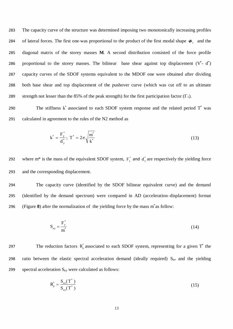
The capacity curve of the structure was determined imposing two monotonically increasing profiles 283
of lateral forces. The first one was proportional to the product of the first modal shape 1ĭ and the 284
diagonal matrix of the storey masses M. A second distribution consisted of the force profile 285
proportional to the storey masses. The bilinear base shear against top displacement (V*- d*) 286
capacity curves of the SDOF systems equivalent to the MDOF one were obtained after dividing 287
both base shear and top displacement of the pushover curve (which was cut off to an ultimate 288
strength not lesser than the 85% of the peak strength) for the first participation factor (1). 289
The stiffness k* associated to each SDOF system response and the related period T* was 290
calculated in agreement to the rules of the N2 method as 291
*
**
*y
*y*
k
m2T;
d
Fk
(13)
where m* is the mass of the equivalent SDOF system, *yF and
*yd are respectively the yielding force 292
and the corresponding displacement. 293
The capacity curve (identified by the SDOF bilinear equivalent curve) and the demand 294
(identified by the demand spectrum) were compared in AD (acceleration–displacement) format 295
(Figure 8) after the normalization of the yielding force by the mass m*as follow: 296
*
*y
ay m
FS
(14)
The reduction factors *R associated to each SDOF system, representing for a given T* the 297
ratio between the elastic spectral acceleration demand (ideally required) Sae and the yielding 298
spectral acceleration Say were calculated as follows: 299
)T(S
)T(SR
*ay
*ae*
(15)

14
Also, the ductility demand r was determined by setting a R--T relationship and 300
substituting the quantities *R and T* previously calculated. The R--T relationships used in N2 301
procedure refers to Miranda & Bertero (1994) and are shown below: 302
)TT(1
T
T)1R( C
Cr
(16)
)TT(R Cr (17)
303
In the original form the N2 method provides the evaluation of the constant ductility demand 304
inelastic spectrum by the use of the above-mentioned R--T relationship to be applied to the 305
elastic spectrum. The relationship in question derives from the observation of the response of SDOF 306
elastic-plastic systems without a reduction in strength in the plastic stage. Unfortunately, several 307
systems cannot be assimilated to an elastic-plastic SDOF system like this because their strength 308
undergoes a not negligible reduction in the post peak stage. Hence the R--T relationship 309
mentioned above is not suitable for the evaluation of the inelastic demand spectrum and, 310
consequently, for the evaluation of the displacement demand. Appropriate R--T relationships for 311
the case of systems that reduce the strength in the plastic stage have been obtained by Dolsek and 312
Fajfar (2004). The shape of these relationships, obtained for different reductions of the ultimate 313
strength, is shown in Fig. 9 and compared with the R--T relationship used by the N2 method in 314
the original form. 315
However, if the capacity of a system is limited to the stage in which a negligible reduction of 316
strength occurs, then the R--T relationship by Miranda and Bertero (1994) becomes more than 317
suitable for the calculation of the performance point. 318
In the case here discussed, a comparison of the displacement capacity with that given by the 319
demand inelastic spectrum obtained the R--T relationship by Miranda and Bertero (1994) is 320
15
possible because the displacement capacity itself is fixed at an ultimate strength not lesser than the 321
85% of the peak strength. This strategy is normally suggested by the current codes. 322
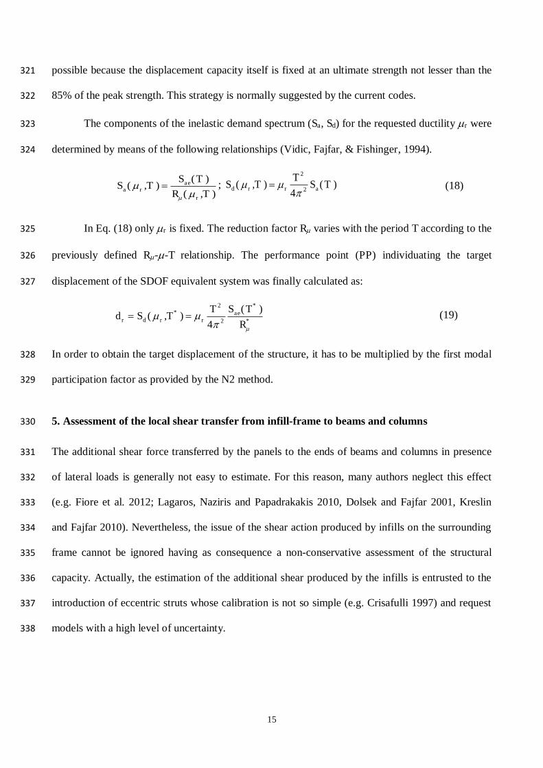
The components of the inelastic demand spectrum (Sa, Sd) for the requested ductility r were 323
determined by means of the following relationships (Vidic, Fajfar, & Fishinger, 1994). 324
)T,(R
)T(S)T,(S
r
aera
; )T(S4
T)T,(S a2
2
rrd
(18)
In Eq. (18) only r is fixed. The reduction factor R varies with the period T according to the 325
previously defined R--T relationship. The performance point (PP) individuating the target 326
displacement of the SDOF equivalent system was finally calculated as: 327
*
*ae
2
2
r*
rdr R
)T(S
4
T)T,(Sd
(19)
In order to obtain the target displacement of the structure, it has to be multiplied by the first modal 328
participation factor as provided by the N2 method. 329
5. Assessment of the local shear transfer from infill-frame to beams and columns 330
The additional shear force transferred by the panels to the ends of beams and columns in presence 331
of lateral loads is generally not easy to estimate. For this reason, many authors neglect this effect 332
(e.g. Fiore et al. 2012; Lagaros, Naziris and Papadrakakis 2010, Dolsek and Fajfar 2001, Kreslin 333
and Fajfar 2010). Nevertheless, the issue of the shear action produced by infills on the surrounding 334
frame cannot be ignored having as consequence a non-conservative assessment of the structural 335
capacity. Actually, the estimation of the additional shear produced by the infills is entrusted to the 336
introduction of eccentric struts whose calibration is not so simple (e.g. Crisafulli 1997) and request 337
models with a high level of uncertainty. 338
16
The idea developed in this paper is that the modeling of infills should be done by concentric struts 339
because of the simplicity of this approach. Further, the additional shear produced by infills in the 340
surrounding frame elements should be calculated by a specific strategy. 341
The focus of this study specifically regards the evaluation of the actual shear transfer to columns, in 342
particular in the base columns, which have also to support the maximum level of shear. Through the 343
paper, it is shown that a shear capacity not sufficient can be simply highlighted by the evaluation of 344
the shear demand in the base columns disregarding the additional shear demand in the upper 345
columns and in the beams. This is consistent with a simplified approach to evaluate if the additional 346
shear demand produced by infills may be a problem. The single strut concentric model has been 347
adopted taking advantage of the procedure provided by Cavaleri & Di Trapani (2015) for the 348
evaluation of the actual shear action in critical sections. The latter makes use of specific correlation 349
coefficients used to determine the rate of axial force on the equivalent strut that is transferred as 350
shear in frame nodal regions. This correlation has been found by a numerical experimental 351
campaign carried out on single infilled frames under lateral loads modeled by using the 352
micromodelling and the macromodelling approaches. The former approach has allowed to evaluate 353
the rate of shear transferred from the infills to the surrounding frame members while the latter has 354
allowed to evaluate the axial force in the equivalent strut. In this experimentation, a very high 355
number of single infilled frames has been analyzed varying the characteristics of frame and infill 356
(weak frame with strong infill, strong frame with weak infill and so on). As a result of the numerical 357
experimentation, a parameter characterizing the single infilled frame has been found. 358
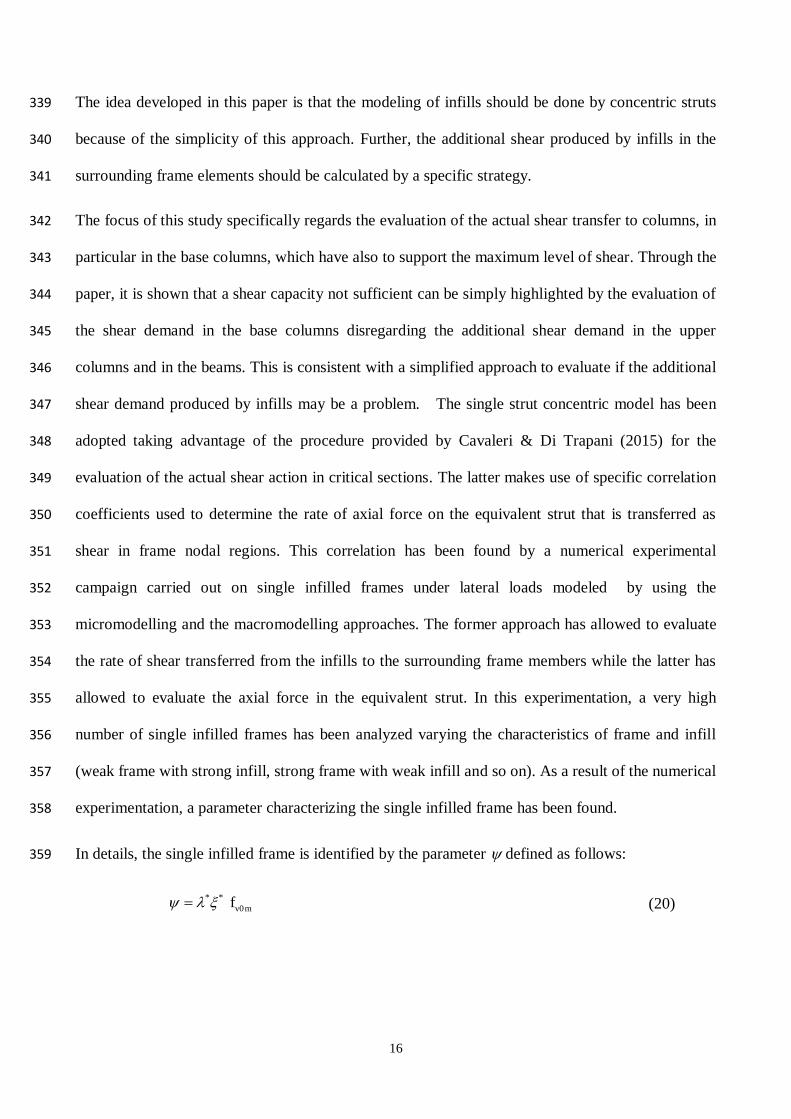
In details, the single infilled frame is identified by the parameter defined as follows: 359
* *v0mf (20)
17
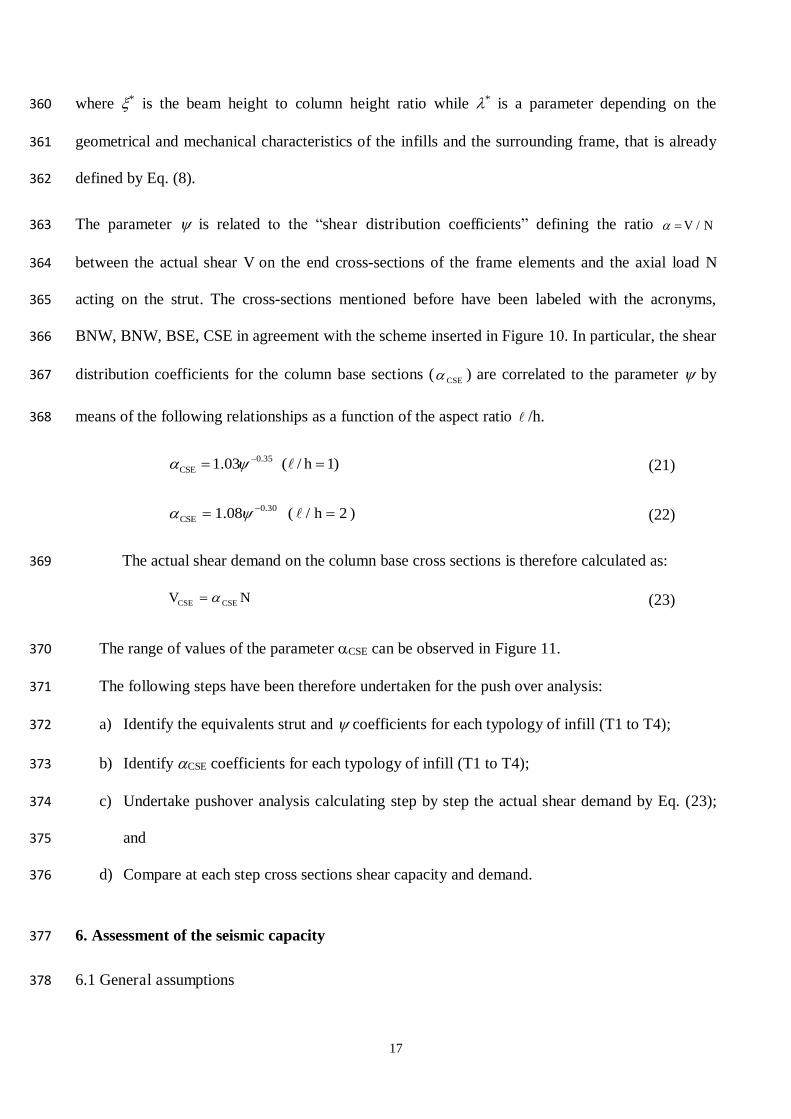
where * is the beam height to column height ratio while * is a parameter depending on the 360
geometrical and mechanical characteristics of the infills and the surrounding frame, that is already 361
defined by Eq. (8). 362
The parameter is related to the “shear distribution coefficients” defining the ratio N/V 363
between the actual shear V on the end cross-sections of the frame elements and the axial load N 364
acting on the strut. The cross-sections mentioned before have been labeled with the acronyms, 365
BNW, BNW, BSE, CSE in agreement with the scheme inserted in Figure 10. In particular, the shear 366
distribution coefficients for the column base sections ( CSE ) are correlated to the parameter by 367
means of the following relationships as a function of the aspect ratio /h. 368
)1/(03.1 35.0 hCSE (21)
)2h/(08.1 30.0CSE (22)
The actual shear demand on the column base cross sections is therefore calculated as: 369
NV CSECSE
(23)
The range of values of the parameter CSE can be observed in Figure 11. 370
The following steps have been therefore undertaken for the push over analysis: 371
a) Identify the equivalents strut and coefficients for each typology of infill (T1 to T4); 372
b) Identify CSE coefficients for each typology of infill (T1 to T4); 373
c) Undertake pushover analysis calculating step by step the actual shear demand by Eq. (23); 374
and 375
d) Compare at each step cross sections shear capacity and demand. 376
6. Assessment of the seismic capacity 377
6.1 General assumptions 378
18
The effect of different levels of modelling of the structure chosen as case study has been 379
highlighted in order to show that as is not enough the modeling of frames neglecting infills, it is not 380
enough the modeling of infills by concentric struts neglecting the additional shear produced by 381
infills on frame members. The effect of different types of structural models for the case study 382
structure has been discussed in order to highlight not only that a modeling neglecting the infills is 383
not appropriate, but also that a modeling considering infills by equivalent concentric struts lead to a 384
strongly not reliable assessment of the safety level. Also, it is shown that the simplicity of the 385
approach based on concentric struts can be maintained if a proper strategy for the assessment of the 386
additional shear is adopted. Finally, how to apply a new strategy for the assessment of the additional 387
shear based on a correlation with the axial force in the equivalent strut is shown. 388
The static pushover analysis (in X and Y direction) and the N2 assessment method has been used. 389
In particular, the following cases were analyzed and compared: 390
BF: No infills (Bare frames) 391
IF: Inclusion of infills by concentric equivalent struts (in this case the model is not able to 392
make the additional shear on columns produced by infills) 393
IF + Local: Inclusion of infills by concentric equivalent struts with the application of an 394
additional new strategy for the evaluation of local shear action 395
The near collapse (NC) limit state, corresponding to a 1463 years return period (0.359 g) has 396
been considered as a reference point (this is consistent with the fact that the building under study 397
serves as a school). The spectral parameters are shown in Table 6. These have been considered 398
based on the seismicity of the area and the subsoil properties. The near collapse (NC) elastic 399
response spectrum is reported in Figure 12 in the acceleration versus displacement (AD) format. 400
6.2 Dynamic characterization 401
A modal analysis has been performed for both BF and IF models. Comparing the results from the 402
BF and IF analysis, a reduction of approximately -75% of the periods of each mode has been found 403
19
(Figure 13(a)) for the IF case, as result of the significant stiffening effect exerted by the masonry 404
wall panels. The reduction of periods is consistent with the fact that an infill may increment the 405
initial stiffness of a frame of over 15 times that means a growing of the stiffness-mass ratio of over 406
15 times and a reduction of 75% of the period. As regards to the level of stiffness increment, the 407
experimental campaign carried out by Cavaleri et al (2005) on infilled frames characterized by clay 408
tile masonry infills shows that this increment is possible (bare frame 17000 N/mm, infilled frame 409
245.000 N/mm). 410
On the other hand, the participating mass ratios in fundamental modes in the X and Y directions 411
found to increase for the IF model (Fig. 13(b)). Such trend reflects a regular distribution of infills in 412
plan and elevation. In the current case, the increase of the participating mass ratios was 413
approximately +50% in both directions. 414
6.3 Pushover analysis (IF and BF models) 415
The pushover analyses performed in X and Y directions for modal and uniform distributions (Figure 416
14), revealed substantial differences in the structural response for the BF and IF cases. In Figure 14, 417
the curve ends represent the near collapse limit state in one or more cross sections, corresponding to 418
their ultimate rotation capacity. Only the responses of the infilled structure along the Y direction 419
exibithed a non negligible reduction of strength in the post peak stage. In details, in the case of 420
modal distribution of the forces, the ultimate strength associated with the ultimate cross section 421
rotation capacity was lesser than the 85% of the peak strength while in the case of uniform 422
distribution of the forces the ultimate strength reached the 90% of the peak strength. Due to the 423
presence of the infills, the increase in stiffness was +700% in the X direction and +500% in the Y 424
direction. A simultaneous increase of overall strength (in the order of +100%) was also recognized 425
due to the presence of the infills. Despite the development of large base shear, a significant 426
reduction of the displacement at the top of the structure was observed (-45% on average). Local 427
ultimate rotations occurred at the base of columns, which suffered a significant axial load variation 428

20
due to the overturning action generated by the presence of the equivalent struts and significantly 429
affecting their ultimate deformation capacity. 430
Also, the collapse mechanisms were significantly different for the IF and BF cases studied. The 431
presence of the infills induced concentration of structural damage on the lower floors and in 432
particular on the ground floor. This can be observed from the drift demand diagrams reported in 433
Figure 15 for all the force profiles considered. The pushover analyses on the BF model showed a 434
different distribution of the damage that generally increases with the height. This is due to the 435
reduction of lateral stiffness from the second to the third floor as it is evident in particular from the 436
pushover analyses carried out in X direction where a large damage (approximately 3%) at the top 437
inter-storey was observed. 438
The seismic performance assessment of the models has been performed in the acceleration-439
displacement diagram by the standard N2 procedure. First, the equivalent SDOF bilinear responses 440
were determined (Figure 16) by the parameters included in Table 7. To this aim the pushover curve 441
of the infilled structure obtained under a modal distribution of the forces (the only one characterized 442
by a ultimate strength lesser than the 85% of the peak strength) was stopped to a value of the 443
ultimate strength of the 85% of the peak strength (see triangle marker in Figure 15-a). In this way 444
the equivalent bilinear response was made consistent with the use of the R--T relationship by 445
Miranda and Bertero (1994) for the determination of the inelastic demand spectrum and the 446
performance point. The bilinear responses (capacity) were compared to the inelastic demand spectra 447
associated each time to the specific values R* ,R , and T* (Figure 17). 448
From the results of the analyses it was found that for the bare frame (BF) model, a lack of 449
deformation capacity was noticeable along Y direction for both modal and uniform profiles. On the 450
other hand, the inclusion of the infills by means of the equivalent struts (IF model) resulted 451
favorably in any case providing positive outcomes for all the loading conditions considered. This 452
result seems to be apparently conflicting with the reduction of the overall deformation capacity 453
21
recognized for the infilled structure but is, however, consistent because of the lower target 454
displacement required by the inelastic demand spectrum as a result of the large increase of strength 455
and stiffness of the system. It should be also noted that within the N2 procedure, the definition of 456
the bilinear equivalent curve follows the rule to interrupt the capacity curve of the SDOF system in 457
correspondence of a loss of strength not greater than 15%. This is consistent with bare systems for 458
which the structural damage largely develops after the peak strength. On the contrary, the large loss 459
of strength, commonly occurring in the post peak branch of infilled RC struts capacity curves (as in 460
IF model), is mainly due to the progressive collapse of infills. The actual ultimate displacement 461
capacity of the RC frame, in the most of experimental cases presented in the literature (e.g. Cavaleri 462
and Di Trapani 2014, Mehrabi and Shing 1996), is typically achieved in correspondence of an 463
overall strength reduction ranging between -20% and -40%. 464
465
6.4 Effects of the infill-frame local shear interaction in pushover analysis (IF+Local model) 466
With reference to the procedure described in Section 5, the results of the pushover analysis for IF 467
model have been processed in order to determine the actual shear demanded to the column base 468
cross sections (IF+Local model). This allowed comparing the shear demand on columns at different 469
steps and their capacity within the same diagram. This kind of approach permitted to identify the 470
step, and then the displacement, at which an eventual shear failure of columns occurred, localizing 471
this event on the overall capacity curve. The shear distribution coefficients used to convert the axial 472
force acting on the equivalent struts into shear demand using Eq. (23), have been calculated 473
according to the expressions provided in Cavaleri & Di Trapani (2015) for the four infilled frame 474
typologies (T1 to T4) recognized and reported in Table 8. 475
The shear capacity of the columns (VR) has been determined according to the following 476
expression provided by the Italian technical code (2008): 477
22
RsRcR VVV (24)
in which RcV and RsV are respectively the contribution to the strength given by the concrete and by 478
the transversal reinforcement. The concrete contribution is evaluated as: 479
db15.0)f100(
k18.0V cp
c
3/1cm1
Rc
with 2d
2001k (25)
where b and d are the base and the effective height of the cross section, c is a safety factor (here 480
assigned equal to 1), 1 is the ratio between the total longitudinal reinforcement and the product b x 481
d and cp is the average compression stress on the column, here calculated as the ratio between the 482
axial force and the area of the cross section. The transversal reinforcement contribution has been 483
obtained using the expression: 484
gcotdi
Af9.0V s
ymRs (26)
in which As / i is the transversal reinforcement area per unit length and cotg is assumed to be equal 485
to 1 in the hypothesis of an inclination of 45° of the concrete resisting strut. The geometrical 486
features of the ground level columns are reported in Table 9. 487
The actual distribution of the shear strength demand (VD), found by the IF+Local procedure 488
has been represented for each of the ground floor columns in terms of base shear against the 489
pushover loading steps (Figure 18). Within the same diagram, the shear capacity curve of the 490
columns VR superimposed. The variability of both the demand and capacity curves at each step 491
depends on the damage state reached by the system and on the compression level acting on each 492
column (cp) accordingly. 493
From the intersection of the curves, the loading step at which the shear demand equals the 494
capacity and consequently the associated displacement corresponding to the first shear failure event 495
23
has been determined. From Figure 18, the shear demand is exceeds the capacity in several cases for 496
the columns which are adjacent to the infills. The same fact cannot be observed in Figures 19 and 497
20 where the shear demand referred to the models IF and BF results lower than the shear capacity. 498
As regards to the model IF+local, the overcoming of the shear capacity of the base columns occurs 499
at really early displacements and before the achievement of the maximum base shear capacity (-50 500
to -40%) detected by the IF model (Figure 21). Thus, failure of the system initiates in the pseudo-501
elastic phase of the capacity curve in correspondence of a base shear level greater than the one 502
associated with the bare frame but followed supposedly by a really limited deformation capacity 503
and load carrying capacity drop. The IF+Local model, by its definition, is able to predict the 504
overcoming of the shear capacity but not how the system evolves beyond this point. Despite this 505
limitation, that can be overcame only by the implementation of shear non-linear hinges 506
appropriately calibrated, the use of IF+Local model permits to detect if and where the presence of 507
the infills may affect the structural response of the system with the occurrence of potential shear 508
failures giving an important warning in all the cases in which shear critical elements surround 509
masonry infills. 510
It is true that pushover analysis is a tool that loses the complex dynamic phenomenon in terms of 511
general degrading and hysteretic behaviour but it gives information about the structural capacity 512
without the need to fix the dynamical parameters (cyclic laws for the materials, for the cross-513
sections, etc,) to which the response is strongly sensitive with risk of much higher errors. 514
Obviously, the possibility to carry out reliable dynamic analysis remain a primary goal of the 515
seismic engineering as also prove the new orientations in the literature (e.g. Dolšek 2012, 2016). 516
7. Conclusions 517
In the paper the assessment of the capacity of the framed r.c. structure of a real school facility is 518
discussed. The aim of the work was to show 519

24
a) the need to not neglect the demand of shear produced by infills as often done when a macro-520
modelling approach for the infills is used, 521
b) the possibility to evaluate in a simple way the additional shear on columns produced by infills 522
even if concentric struts are used thanks to a correlation between equivalent strut axial force and 523
additional shear on columns, 524
c) the applicability in the practice of the correlation above mentioned, 525
d) to prove that the shear collapse can occur even before the reaching of the flexural strength, 526
e) to prove that, in the frame of the simplified approaches, in order to obtain a warning about the not 527
sufficient shear capacity, focusing the attention on the structure base columns and disregarding the 528
additional shear demand in the upper columns and in the beams may be a solution. 529
Different modelling approaches were used for the structure in question, namely: (a) bare frame 530
model (BF model); (b) frames with concentric struts for the infills (IF model); and (c) frames with 531
concentric struts for the infills with prediction of local shear action (IF+Local model). 532
The N2 method was used for the assessment of the structural capacity. The analyses highlighted 533
that 1) the presence of the infill masonry walls (modeled by a concentric equivalent strut) as 534
expected increases the overall strength and stiffness of the system and decreases displacement 535
capacity because of the anticipated achievement of the ultimate rotation of column cross-sections 536
caused by the strong axial load variation arising; 537
2) the use of concentric struts fails in the assessment of the safety level because the additional shear 538
demand on columns due to infills is not provided; 539
3) concentric struts can provide more realistic assessments only in the cases in which the columns 540
of the RC frames have an adequate shear strength; otherwise, shear failures may occur and the 541
actual capacity can be appraised only by implementing shear inelastic response at column ends; 542
25
4) the additional shear in the columns may produce a strong reduction of the capacity as in the case 543
discussed here so to make absolutely unrealistic the evaluation of the structural capacity when the 544
modeling of infills is done by concentric struts; 545
5) this result is often not be expected as the fact that many authors disregard the additional shear 546
when they use concentric struts in the assessment of structure capacity proves; 547
6) the hypothesis of concentric equivalent strut, very simple from the modeling point of view, is, 548
however, possible if a strategy for the evaluation of the additional shear on columns is coupled; 549
7) a simple but strong correlation between the additional shear demand and the strut axial force 550
given in an analytical form, obtained after a numerical experimentation on a very high number of 551
infilled frame types, is available and usable for the practical applications as that here presented; 552
8) the above correlation allowed, maintaining the model simplicity, to recognize a capacity of the 553
structure, different from that obtainable in general by using concentric struts, without any 554
complication in the analyses; 555
9) for the aim to obtain a warning about an insufficient shear capacity, as here proved, the attention 556
may be focused on the additional shear demand to the base columns disregarding the additional 557
shear demand to the upper columns and the beams, this being consistent with an approach 558
simplified to the problem. 559
References 560
Asteris, P.G., Cavaleri, L., Di Trapani, F., and Sarhosis, V. (2015). A macro-modelling approach 561
for the analysis of infilled frame structures considering the effects of openings and vertical loads. 562
Structure and Infrastructure Engineering, DOI: 10.1080/15732479.2015.1030761. 563
Asteris, P.G. (2003). Lateral stiffness of brick masonry infilled plane frames. ASCE Journal of 564
Structural Engineering, 129, 1071 –1079. 565
Bertoldi, S.H., Decanini, L.D., and Gavarini, C. (1993). Telai tamponati soggetti ad azioni sismiche, 566
un modello semplificato: confronto sperimentale e numerico. Proceedigs of 6th ANIDIS 567
Conference, Perugia, Italy. 568

26
Campione, G., Cavaleri, L., Macaluso, G., Amato, G., and Di Trapani, F. (2015). Evaluation of 569
infilled frames: an updated in-plane-stiffness macro-model considering the effects of vertical 570
loads. Bullettin of Earthquake Engineering, 13(8): 2265-2281. 571
Campione, G., Cavaleri, L., Di Trapani, F., Macaluso, G., and Scaduto (2016). G. Biaxial 572
deformation and ductility domains for engineered rectangular RC cross-sections: A parametric 573
study highlighting the positive roles of axial load, geometry and materials. Engineering 574
Structures, 107: 116-134. 575
Cavaleri, L., and Di Trapani, F., (2014). Cyclic response of masonry infilled RC frames: 576
Experimental results and simplified modelling. Soil Dynamics and Earthquake Engineering, 577
65, 224-242. 578
Cavaleri, L., and Di Trapani. F. (2015). Prediction of the additional shear action on frame members 579
due to infills. Bulletin of Earthquake Engineering, 13(5): 1425-1454. 580
Cavaleri, L., Fossetti, M., and Papia, M. (2005). Infilled frames: developments in the evaluation of 581
cyclic behavior under lateral loads. Structural Engineering and Mechanics, 21(4), 469-94. 582
Cavaleri, L., Papia, M., Di Trapani, F., Macaluso, G., and Colajanni, P. (2014). Definition of 583
diagonal Poisson's ratio and elastic modulus for infill masonry walls. Mat. and Struct, 47(1-2): 584
239-262. 585
Celarec, D., Dolšek, M. (2013). Practice-oriented probabilistic seismic performance assessment of 586
infilled frames with consideration of shear failure of columns. Earthquake Engng Struct. Dyn. 587
42:1339–1360. 588
Chrysostomou, C.Z., Gergely, P., and Abel, J.F. (2002). A six-strut model for nonlinear dynamic 589
analysis of steel infilled frames. Int. J. Struct. Stab. Dyn., 2(3): 335–353. 590
Colajanni, P., Cucchiara, C., and Papia, M. (2012). Sostenibilità di interventi di miglioramento 591
sismico di strutture in c.a. non danneggiate. Editors G. Manfredi, C. Nuti. Aracne, Rome, 2012. 592
Crisafulli, F.J. (1997). Seismic behaviour of reinforced concrete structures with masonry infills. 593
PhD Thesis, University of Canterbury, New Zealand. 594
D.M. LL. PP. 14 Gennaio 2008. (2008). Nuove norme tecniche per le costruzioni. 595
Di Trapani, F., Macaluso, G., Cavaleri, L., and Papia, M. (2015). Masonry infills and RC frames 596
interaction: literature overview and state of the art of macromodeling approach. European 597
Journal of Environmental and Civil Engineering, 19(9):1059-1095. 598
Dolšek, M. (2012). Simplified method for seismic risk assessment of buildings with consideration 599
of aleatory and epistemic uncertainty. Structure and Infrastructure Engineering, 8:10, 939-953. 600
27
Dolšek, M. (2016). Analytic Fragility and Limit States [P(EDP|IM)]: Nonlinear static procedures. In 601
Encyclopaedia of Earthquake Engineering, Beer M, Kougioumtzoglou IA, Patelli E, Au IS-K 602
Eds., 87-94. 603
Dolšek, M., and Fajfar, P. (2004). Inelastic spectra for infilled reinforced concrete frames. 604
Earthquake Engng Struct. Dyn., 33:1395–1416. 605
Dolšek, M., and Fajfar, P. (2005).Simplified non-linear seismic analysis of infilled reinforced 606
concrete frames. Earthquake Engng Struct. Dyn., 34:49–66. 607
Dolšek, M., and Fajfar, P. (2008).The effect of masonry infills on the seismic response of four 608
storey reinforced concrete frame - a deterministic assessment. Engineering Structures, 609
30(7):1991-2001. 610
Doudoumis, I.N. and Mitsopoulou, E.N. (1986). Non-linear analysis of multi-storey infilled frames 611
for unilateral contact condition. Proc of 8th European Conference on Earthquake Engineering, 612
Lisbon. 613
El-Dakhakhni, W., Elgaaly, M., and Hamid, A. (2003). Three-Strut Model for Concrete Masonry-614
Infilled Steel Frames. J. Struct. Eng. (ASCE), 129(2), 177–185 615
Eurocode 8 (2004). Design of structures for earthquake resistance—Part 1: General rules, seismic 616
actions and rules for buildings. European Committee for Standardization, Brussels. 617
Fajfar, P. (2000). A nonlinear analysis method for performance-based seismic design. Earthquake 618
Spectra, 16: 573–92. 619
Himaja G.V. S., Ashwini, L. K., Jayaramappa, N. (2015). Comparative Study on Non-Linear 620
Analysis of Infilled Frames for Vertically Irregular Buildings. International Journal of 621
Engineering Science Invention, 4: 42-51. 622
Hognestad, E. (1951). A study of combined bending and axial load in reinforced concrete members. 623
Bulletin Series No. 399, University of Illinois Engineering Experiment Station. 624
Holmes, M. (1961). Steel frames with brickwork and concrete infilling. Proc. of Institution of Civil 625
Engineers, Paper No.6501:473-478. 626
Kakaletsis, D.J., and Karayannis, C.G. (2009). Experimental investigation of infilled reinforced 627
concrete frames with openings. Struct J (ACI), 106(2):132-141. 628
Klingner, R.E., and Bertero, V.V. (1978). Earthquake resistance of infilled frames. J Struct Eng 629
(ASCE), 1978;104(6):973-89. 630
Koutromanos, I., and Shing, P.B. (2012). A Cohesive Crack Model to Simulate Cyclic Response of 631
Concrete and Masonry Structures. ACI Structural Journal, 109(3): 349-358. 632
28
Koutromanos, I., Stavridis, A., Shing, P.B., and Willam, K. (2011). Numerical modelling of 633
masonry-infilled RC frames subjected to seismic loads. Computers and Structures 89, 1026-634
1037. 635
Lima, C., De Stefano, G., Martinelli, E. (2014). Seismic response of masonry infilled RC frames: 636
practice-oriented models and open issues. Earthquakes and Structures, 6:409-436 637
Madan, A., Gupta, A., Hashmi, A. K. (2015). Pushover Analysis of Masonry Infilled Reinforced 638
Concrete Frames for Performance Based Design for Near Field Earthquakes. International 639
Journal of Civil, Environmental, Structural, Construction and Architectural Engineering, 640
9:1101-1107 641
Mainstone, R.J. (1971). On the stiffness and strength of infilled frames. Proc Inst Civil Eng, Suppl 642
(IV), Lond, Paper 7360S:57–89. 643
Mainstone, R.J. (1974). Supplementary note on the stiffness and strength of infilled frames. Current 644
Paper CP 13/74, Building Research Station, UK. 645
Martinelli, E., Lima, C. and De Stefano, G. (2015). A simplified procedure for Nonlinear Static 646
Analysis of masonry infilled RC frames. Engineering Structures, 101:591-608. 647
Mehrabi A.B., Shing P.B., Schuler, .M.P., and Noland, J.L. (1996). Experimental evaluation of 648
masonry-infilled RC frames. J Struct Eng (ASCE), 122(3):228-37. 649
Mehrabi A.B., and Shing P.B., Finite element modelling of masonry-infilled RC frames”, J. Struct. 650
Eng., Vol. 123, No. 5, 1997, p. 604-13. 651
Miranda, E., and Bertero VV. (1994). Evaluation of strength reduction factors for earthquake 652
resistant design. Earthquake Spectra, 10: 357-379, 1994. 653
Panagiotakos, T.B., and Fardis, M.N. (1996). Seismic response of infilled RC frames structures. 654
Proc. of XXI WCEE, Acapulco, Mexico. 655
Papia, M., Cavaleri, L., and Fossetti, M. (2003). Infilled frames: developments in the evaluation of 656
the stiffening effect of infills. Structural engineering and mechanics, 16(6), 675-93. 657
Saneinejad, A., and Hobbs, B. (1995). Inelastic design of infilled frames. J Struct Eng (ASCE); 658
121(4): 634-50. 659
Shing P.B., and Mehrabi A.B., (2002). Behavior and analysis of masonry-infilled frames. Prog. 660
Struct. Eng. Mater., (3): 320-31. 661
Stafford Smith, B. (1966). Behavior of the square infilled frames. Struct. Div. (ASCE), 92(1), 381-662
403. 663
Stafford Smith, B., and Carter, C. (1969). A method for analysis for infilled frames. Proc. of 664
Institution of Civil Engineers, Paper No.7218, 31-48. 665

29
Uva, G., Porco, F., and Fiore, A. (2012). Appraisal of masonry infill walls effect in the seismic 666
response of RC framed buildings: a case study. Engineering Structures, 34:514–26. 667
Vidic, T., Fajfar, P., and Fishinger, M. (1994). Consistent inelastic design spectra: strength and 668
displacement: Evaluation of strength reduction factors for earthquake resistant design. 669
Earthquake Spectra, 10: 357-379. 670
Žarnić, R., and Gostič, S. (1997). Masonry infilled frames as an effective structural subassemblage. 671
Seismic design methodologies for the next generation of codes (Fajfar, Krawinkler, editors), 672
Rotterdam. 673
674