influence of chunky graphite on latent heatmit.imt.si/revija/izvodi/mit181/pokopec.pdf · adjusted...
TRANSCRIPT

I. MIHALIC POKOPEC et al.: INFLUENCE OF CHUNKY GRAPHITE ON LATENT HEAT59–65
INFLUENCE OF CHUNKY GRAPHITE ON LATENT HEAT
VPLIV CHUNKY GRAFITA NA LATENTNO TOPLOTO
Ivana Mihalic Pokopec1, Primo` Mrvar2, Branko Bauer1
1University of Zagreb, Faculty of Mechanical Engineering and Naval Architecture, Ivana Lucica 5, 10002 Zagreb, Croatia2University of Ljubljana, Faculty of Natural Science and Engineering, Lepi pot 1, 1000 Ljubljana, Slovenia
Prejem rokopisa – received: 2017-07-21; sprejem za objavo – accepted for publication: 2017-10-02
doi:10.17222/mit.2017.122
The study presents the results of investigations of the thermal effects that take place during the heating and cooling of samplesof the spheroidal graphite cast iron with different amounts of chunky graphite (CHG) in the microstructure. In order to obtain adifferent amount of CHG, cone blocks � 300 mm × 350 mm were casted. Two different test melts, EN-GJS-400-18 with 0.7 %of the mass fraction of Ni and EN-GJS-400-15 with 3.5 % of the mass fraction of Si were used. From each block three samples,with different cooling rates, were prepared. For studies of phase transformations, the technique of differential scanningcalorimetry (DSC) was used. The microstructure was examined before and after DSC by optical microscopy. The obtainedvalues of the enthalpy of melting and solidification differ and depend on the initial microstructure of the examined samples. Theremelting of samples results in magnesium oxidation and significant changes in the eutectic morphology, which, at roomtemperature, consists of fine and/or coarse undercooled types of graphite with a lamellar morphology.
Keywords: chunky graphite, DSC, graphite morphology, heating and cooling
Raziskava predstavlja rezultate toplotnih efektov med segrevanjem in hlajenjem vzorcev iz sive litine s kroglastim grafitom zrazli~nimi dele`i chunky grafita (CHG). Z namenom pridobitve razli~nih dele`ev chunky grafita, so bili vliti ulitki sto`~asteoblike z zgornjim premerom 300 mm in vi{ino 350 mm. Uporabljeni sta bili dve razli~ni talini, EN-GJS-400-18, z 0,7 masnega% Ni in EN-GJS-400-15, s 3,5 masnimi % Si. Iz vsakega bloka so bili pripravljeni trije vzorci z razli~nimi ohlajevalnimihitrostmi. Za raziskave faznih transformacij je bila uporabljena diferen~na vrsti~na kalorimetrija (DSC). Vzorci so bili preiskaniz opti~no metalografijo pred in po DSC analizi. Izmerjene vrednosti entalpij taljenja in strjevanja se razlikujejo in so odvisne odmikrostrukture preiskanih vzorcev. Posledica pretaljevanja vzorcev je oksidacija magnezija in posledi~no spremembe vmorfologiji evtektika, ki pri sobni temperaturi vsebuje fine in/ali grobe oblike podhlajenega lamelnega grafita.
Klju~ne besede: chunky grafit, DSC, morfolgija grafita, segrevanje in ohlajanje
1 INTRODUCTION
The manufacture of thick-walled castings of sphe-roidal graphite cast iron represents an area of continuinggrowth, and this trend is set to continue at least over thenext 20 years. This refers primarily to the manufacture ofcastings for wind farms, manufacture of containers forthe permanent storage of nuclear waste and the industryfor heavy-duty vehicles.1–6 Future applications of thick-walled castings of spheroidal graphite cast irons willrequire increasingly thicker walls. In parallel, the re-quirements for mechanical properties will grow too, thusleading to a growing importance of the high-qualityspheroidal morphology of the graphite. Every dege-neration of graphite, which is a frequent and undesirablephenomenon in the manufacture of thick-walled castings,leads to a decrease of the mechanical properties and veryoften results in the discarding of such castings.7 Themost detrimental among these deteriorations is chunkygraphite. This defect mainly occurs in the thermal centreof the thick-walled cast parts and causes a decrease inthe mechanical properties, especially tensile strength,elongation and fatigue strength.3–10
The main causes for the occurrence of CHG are slowcooling rate and chemical composition. The slower the
cooling rate, the greater, the fewer and more irregular thenodules. These conditions favour the formation of CHG.As for the chemical composition, numerous studies haveestablished that Ce, Si, Ni and Ca promote the formationof chunky graphite.1,3,5,6,9
It is well-known that chunky graphite forms during aeutectic reaction. However, there is a disagreement aboutwhether chunky graphite forms in the melt during theearly phase of eutectic solidification or on locations ofthe remaining melt towards the end of the eutectic solidi-fication. Likewise, it is not known whether the sphero-idal or chunky graphite forms first.
According to H. Itofuji and H. Uchikava11 the for-mation and growth of chunky graphite occurs in the laterphase of eutectic solidification, when the growth of thenodule is almost in its final phase. The formation ofchunky graphite in the later phase of eutectic solidifica-tion is in line with H. Nakae et al.12 According to Z.Zhang et al.13 chunky graphite forms in the middle ortowards the end of eutectic solidification at the auste-nite/liquid interface and continues to grow towards therest of the melt. On the other hand, according to J.Zhou,14,15 chunky graphite forms in the initial phase ofeutectic solidification.
Materiali in tehnologije / Materials and technology 52 (2018) 1, 59–65 59
UDK 620.1/.2:669.131.6:621.78.08 ISSN 1580-2949Original scientific article/Izvirni znanstveni ~lanek MTAEC9, 52(1)59(2018)

The DSC method enables us to follow the phasetransformations during the heating and cooling of sam-ples and the enthalpies with reference to reactions duringmelting and solidification and transformation in the solidstate.16,17 In this paper, the DSC method was used todetermine the characteristic temperatures and enthalpiesduring heating and cooling. By using samples with adifferent share of CHG, an attempt was made to identifya relation to solidification enthalpy and the influence ofCHG content on newly formed microstructure. In orderto analyse more easily and precisely the DSC coolingcurves of samples, a metallographic analysis was per-formed before and after the analysis by an optical micro-scope.
2 EXPERIMENTAL PROCEDURE
Two different test melts were used: EN-GJS-400-18with 0.7 % of the mass fraction of Ni and EN-GJS-400-15 with 3.5 % of the mass fraction of Si.
The test castings used in this study were cone blockswith diameter of 300 mm and a height of 350 mm, Fig-ure 1, to enable investigation of the influence of differentcooling rates on chunky-graphite formation.
Two moulds (M1, M2) were produced from sodiumsilicate bonded sand. For both moulds, KALPUR directpouring process was used.
Both test melts were produced in a 5.6 t capacitymedium frequency induction furnace. The charge mate-rial consisted of grey pig iron (Sorelmetal®), steel scrapand returns as listed in Table 1. In order to increasecarbon and silicon contents and the nucleation ability ofthe melt, SiC (~92 % of the mass fraction of SiC) wasadded into the furnace with the metallic charge. Also, forincreasing Si content, in the second melt 2.3 % of themass fraction of FeSi was added. Once melting wasfinished, the chemical composition of the metal wasadjusted according to carbon and silicon evaluation givenby thermal analysis and spectrometric analysis on thecoupon for the other elements.
For both moulds, the spheroidising treatment wascarried out in a dedicated ladle of 200 kg capacity byadding ~ 1.8 % of the mass fraction of FeSiMg alloy(44–48 % of the mass fraction of Si, 3.5–3.8 % of themass fraction of Mg, 0.9–1.1 % of the mass fraction ofCa, 0.5–1.2 % of the mass fraction of Al, 0.6–0.8 % ofthe mass fraction of RE, Fe bal.) and 0.2 % of the massfraction of cover alloy (46–50 % of the mass fraction ofSi, 1.8–2.2 % of the mass fraction of Ba, 0.4-0.6 % ofthe mass fraction of Ca, 0.5–1.0 % of the mass fraction
of Al, Fe bal.) using the sandwich method at ~1480 °C.The FeSiMg alloy was positioned at the bottom of thecasting ladle and then covered by cover alloy beforepouring the iron from the furnace. In first casting ladle0.7 % of the mass fraction of Ni and in the secondcasting ladle 0.7 % of the mass fraction of FeSi wasadded on the bottom before pouring the iron from thefurnace.
After the treatment, slag was removed from the meltsurface and the melt was poured into the mould. Holdingtime was ~3 min. Second inoculation (in-stream) duringpouring in the mould was performed by adding 0.45 %of the mass fraction of inoculant containing Ce (70–76 %of the mass fraction of Si, 1.5–2.0 % of the mass fractionof Ce, 0.75–1.25 % of the mass fraction of Al, > 1 % ofthe mass fraction of O and S, Fe bal.). Pouring tem-perature for both moulds was 1380 °C and pouring time27 s.
Just before pouring the melt in the mould, the chilledcoupon was analysed by optical emission spectrometer(ARL 3460). C and Si contents were determined fromthe results of thermal analysis using the ATAS® system.Chemical composition is listed in Table 2.
Each cylindrical block was afterwards sectionedalong the vertical symmetry plane to evaluate the zoneaffected by CHG, and then one half of each block wassectioned along the horizontal symmetry plane 50 mmfrom the base of the cone. From the bottom part of thesectioned cone, the slice of 10 mm thickness was thentaken for sample preparation.
I. MIHALIC POKOPEC et al.: INFLUENCE OF CHUNKY GRAPHITE ON LATENT HEAT
60 Materiali in tehnologije / Materials and technology 52 (2018) 1, 59–65
Figure 1: Pattern used in experiment
Table 1: Charge materials used for melting, in mass fractions
TotalSorel-metal®
(w/%)
Returns(w/%)
Steelscrap(w/%)
SiC(w/%)
FeSi(w/%)
5.6 t 70 21 9 0.1 0.2*
*2,3 (w/%) for 2nd melt
Table 2: Chemical composition of the melts
ConeNo.
In mass fractions, (w/%)C Si Mn S P Mg Co Ni Cr Cu Sn Mo Ti Al ACEL*
1 3.25 1.75 0.160 0.011 0.032 0.036 0.017 0.720 0.030 0.016 0.004 0.003 0.007 0.0095 4.172 2.91 3.46 0.162 0.006 0.034 0.059 0.016 0.026 0.030 0.016 0.006 0.003 0.011 0.0247 4.24
For DSC, three samples with three different coolingrates (from the edge to the centre) from each slice wereprepared, Figure 2. Cooling rates were: 0.036, 0.022 and0.016 °C/s. The sampling locations were determined bysimulation of the casting and solidification processes.Samples were � 5 mm × 4 mm in size. Samples of cone1 were marked as 1-D1, 2-D2 and 3-D3, and of cone 2 as2-D1, 2-D2 and 2-D3.
Differential scanning calorimetry or DSC with ther-mogravimetry was carried out using a simultaneousthermal analyser NETZSCH STA 449 F3 Jupiter® at acooling/heating rate of 10 K/min, Figure 3. Holdingtemperature was 1400 °C and holding time 1 minute.
The metallographic analysis was done by opticalmicroscope (Olympus BX 61) which was equipped witha system for automatic image processing (Analysis®
Materials Research Lab). The samples were etched in a3 % nital solution. Metallographic analysis was carriedout on the same samples for DSC, before and after thecalorimetric measurements.
3 RESULTS
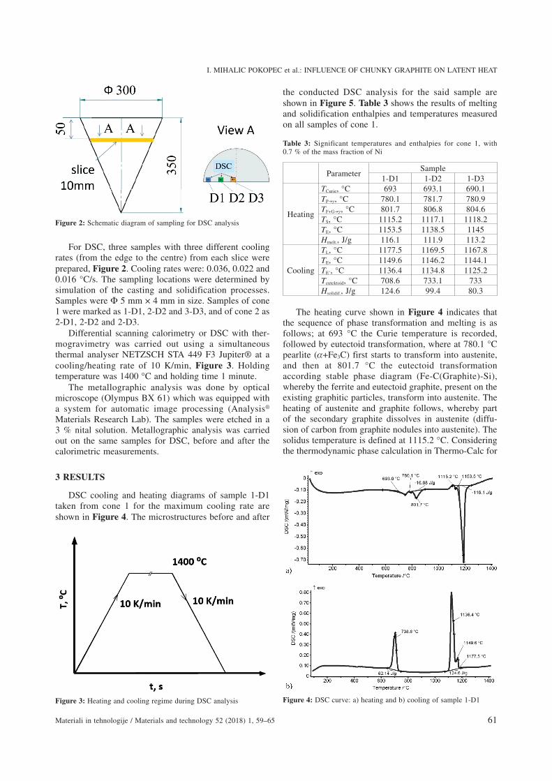
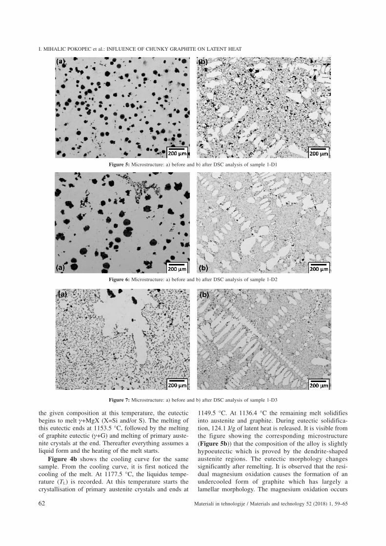
DSC cooling and heating diagrams of sample 1-D1taken from cone 1 for the maximum cooling rate areshown in Figure 4. The microstructures before and after
the conducted DSC analysis for the said sample areshown in Figure 5. Table 3 shows the results of meltingand solidification enthalpies and temperatures measuredon all samples of cone 1.
Table 3: Significant temperatures and enthalpies for cone 1, with0.7 % of the mass fraction of Ni
ParameterSample
1-D1 1-D2 1-D3
Heating
TCurie, °C 693 693.1 690.1TP� , °C 780.1 781.7 780.9TF+G� , °C 801.7 806.8 804.6TS, °C 1115.2 1117.1 1118.2TE, °C 1153.5 1138.5 1145Hmelt., J/g 116.1 111.9 113.2
Cooling
TL, °C 1177.5 1169.5 1167.8TE, °C 1149.6 1146.2 1144.1TE’, °C 1136.4 1134.8 1125.2Teutektoid, °C 708.6 733.1 733Hsolidif., J/g 124.6 99.4 80.3
The heating curve shown in Figure 4 indicates thatthe sequence of phase transformation and melting is asfollows; at 693 °C the Curie temperature is recorded,followed by eutectoid transformation, where at 780.1 °Cpearlite (+Fe3C) first starts to transform into austenite,and then at 801.7 °C the eutectoid transformationaccording stable phase diagram (Fe-C(Graphite)-Si),whereby the ferrite and eutectoid graphite, present on theexisting graphitic particles, transform into austenite. Theheating of austenite and graphite follows, whereby partof the secondary graphite dissolves in austenite (diffu-sion of carbon from graphite nodules into austenite). Thesolidus temperature is defined at 1115.2 °C. Consideringthe thermodynamic phase calculation in Thermo-Calc for
I. MIHALIC POKOPEC et al.: INFLUENCE OF CHUNKY GRAPHITE ON LATENT HEAT
Materiali in tehnologije / Materials and technology 52 (2018) 1, 59–65 61
Figure 4: DSC curve: a) heating and b) cooling of sample 1-D1Figure 3: Heating and cooling regime during DSC analysis
Figure 2: Schematic diagram of sampling for DSC analysis
the given composition at this temperature, the eutecticbegins to melt +MgX (X=Si and/or S). The melting ofthis eutectic ends at 1153.5 °C, followed by the meltingof graphite eutectic ( +G) and melting of primary auste-nite crystals at the end. Thereafter everything assumes aliquid form and the heating of the melt starts.
Figure 4b shows the cooling curve for the samesample. From the cooling curve, it is first noticed thecooling of the melt. At 1177.5 °C, the liquidus tempe-rature (TL) is recorded. At this temperature starts thecrystallisation of primary austenite crystals and ends at
1149.5 °C. At 1136.4 °C the remaining melt solidifiesinto austenite and graphite. During eutectic solidifica-tion, 124.1 J/g of latent heat is released. It is visible fromthe figure showing the corresponding microstructure(Figure 5b)) that the composition of the alloy is slightlyhypoeutectic which is proved by the dendrite-shapedaustenite regions. The eutectic morphology changessignificantly after remelting. It is observed that the resi-dual magnesium oxidation causes the formation of anundercooled form of graphite which has largely alamellar morphology. The magnesium oxidation occurs
I. MIHALIC POKOPEC et al.: INFLUENCE OF CHUNKY GRAPHITE ON LATENT HEAT
62 Materiali in tehnologije / Materials and technology 52 (2018) 1, 59–65
Figure 7: Microstructure: a) before and b) after DSC analysis of sample 1-D3
Figure 6: Microstructure: a) before and b) after DSC analysis of sample 1-D2
Figure 5: Microstructure: a) before and b) after DSC analysis of sample 1-D1

despite the inert atmosphere of argon in the DSC testingdevice. At the end of solidification the cooling of themicrostructure follows, which consists of primary auste-nite and eutectic ( +G). It is interesting to note that thesecond eutectic (MgX+ ) recorded on the heating curvewas not recorded during the cooling of the same sample,which proves that the MgSi decomposed in Mg whichoxidized and in Si which remained in the melt. At 708.6°C starts the eutectoid transformation of both austenites(primary and eutectic) into ferrite and graphite and/orpearlite.
The heating and cooling curves of samples 1-D2 and1-D3 are characterised by the existence of the same cha-racteristic temperatures, which means that the sequenceof phase transformations and melting/solidification ofsingle phases is the same. Images of microstructurebefore and after testing are shown in Figures 6 and 7.
The results of the DSC analysis of samples of cone 2are shown in Table 4. Beside the DSC analysis results,the images of microstructure in the initial phase and aftertesting are also shown, Figures 8 to 10.
By analysing the heating and cooling curves of cone2 samples, it has been observed that samples undergo thesame phase transformations and melting/solidificationsequence as the samples of cone 1. The main differenceto the samples of cone 1 is that the eutectoid transfor-
mation temperatures are shifted towards higher values asa result of high content of Si in cone 2. Likewise, thetransformation peaks of pearlite and ferrite in austeniteon the heating curve are less noticeable. As a matter offact, these two peaks often overlap.17 This is why it isdifficult to establish the exact temperature at the end ofeutectic transformation of pearlite in austenite and at thebeginning of the transformation of ferrite into graphiteand austenite. During heating, also in cone 2, the exis-
I. MIHALIC POKOPEC et al.: INFLUENCE OF CHUNKY GRAPHITE ON LATENT HEAT
Materiali in tehnologije / Materials and technology 52 (2018) 1, 59–65 63
Figure 9: Microstructure: a) before and b) after DSC analysis of sample 2-D2
Figure 8: Microstructure: a) before and b) after DSC analysis of sample 2-D1
Table 4: Significant temperatures and enthalpies for cone 2, with3.5 % of the mass fractions of Si
ParameterSample
2-D1 2-D2 2-D3
Heating
TCurie, °C 711.3 712.7 710.4TP� , °C 851.5 853.3 853.7TF+G� , °CTS, °C 1127.1 1126.9 1127.3TE, °C 1148.7 1148.2 1144.6Hmelt., J/g 109 107 125.4
Cooling
TL, °C 1179 1167.5 1169.6TE, °C 1150.4 1148.2 1152.7TE‘, °C 1131.8 1129.7 1131.7Teutectoid, °C 801.4 802.3 797.3Hsolidif., J/g 122 89.6 132.2

tence of the second eutectic has been noticed, which wasabsent during re-cooling.
4 DISCUSSION
From the heating results with reference to samples ofcone 1, it is visible that melting enthalpy differs slightlyamong samples with different cooling rates, Table 3. Bycomparing the cooling results for the same cone, itemerges that reference solidification temperatures shifttowards lower values as the cooling rate decreases fromthe edge towards the centre. The latent heat releasedduring solidification decreases significantly.
By examining the images of microstructure beforethe DSC analysis, it can be clearly observed that the con-tent of chunky graphite in cone 1 with 0.7 % of the massfraction of Ni increases from the edge towards thecentre. So the sample 1-D3, Figure 7a, shows practicallya 100 % of eutectic graphite with chunky graphite mor-phology, whereas the sample 1-D1, Figure 5a, has amicrostructure of regular spheroidal graphite cast iron. Inaddition, different microstructures were obtained afterthe conducted DSC analysis. Microstructure consists of aprimary dendritic austenite and a undercooled form ofgraphite with a certain content of irregularly distributedgraphite accumulations. The undercooled graphite exhi-bits a coarse morphology in sample 1-D1, a mixed mor-phology (finer more than coarser undercooled graphite)in sample 1-D2, and the finest morphology in sample1-D3. The finer the undercooled graphite, the smaller thegraphite accumulations, Figures 5 to 7b.
The difference in the microstructure of samplesbefore and after DSC analysis occurs as a result ofmagnesium oxidation during reheating, which caused theabsence of conditions for formation of the spheroidalgraphite and the growth of graphite in the form oflamellar graphite in the undercooled form. The contentof residual magnesium decreased to approximately0.01 %.18
Based on the results of DSC analysis and analysis ofmetallographic images of samples it can be concludedthat the lower the enthalpy during solidification, the finer
the undercooled graphite. In the sample 1-D3 with thefinest morphology of undercooled graphite, the value ofsolidification enthalpy amounts to 80.3 J/g, in the sample1-D2 it amounts to 99.4 J/g, and in the sample 1-D1 to124.6 J/g (spheroidal graphite before the analysis, that is,the coarsest graphite after the analysis). The same con-clusion is valid for characteristic solidification tempera-tures. Table 3 shows also the temperature at the beginn-ing of the eutectoid transformation Teutectoid. In the sample1-D1 with the lowest temperature Teutectoid = 708.6 °C, thelamellar morphology eutectic with the coarsest shapecould be observed, Figure 5 b) (diffusion paths of carbontransport from austenite to graphitic particles are moredistant compared to samples 1-D2 and 1-D3).
By comparing the heating results for samples of cone2, Table 4, it can be seen that there is not much diffe-rence between the characteristic temperatures and melt-ing enthalpy with reference to samples 2-D1 and 2-D2.The sample 2-D3 with respect to samples 2-D1 and 2-D2has a significantly lower value of TE and a higher valueof melting enthalpy.
I. MIHALIC POKOPEC et al.: INFLUENCE OF CHUNKY GRAPHITE ON LATENT HEAT
64 Materiali in tehnologije / Materials and technology 52 (2018) 1, 59–65
Figure 11: Comparison of enthalpies of melting and solidification ofsamples from cones 1 and 2
Figure 10: Microstructure: a) before and b) after DSC analysis of sample 2-D3

By examining the microstructure images before theDSC analysis, it could be clearly observed that the con-tent of chunky graphite in cone 2 with 3.5 % of the massfraction of Si does not increase from the edge towardsthe centre, but rather the opposite. In samples 2-D1 and2-D2, before the conducted testing, the graphite eutectichas an equal share of spheroidal and chunky morpho-logy, Figures 8a and 9a. In the sample 2-D3, beforetesting, graphite eutectic with spheroidal morphologyprevails, whereas chunky graphite is present with arather low share, Figure 10a, therefore the melting en-thalpy differ compared to samples 2-D1 and 2-D2. TE islower for approximately 4 °C, whereas Hmelt. is signifi-cantly higher, for approximately 16 J/g, as shown inTable 4.
By analysing the microstructure images it can beconcluded that the microstructure of samples aftercooling consists of primary austenite dendrites and gra-phite eutectic with morphology of undercooled lamellargraphite, Figures 8 to 10b, as in cone 1. It is a slightlyhypoeutectic alloy. The greater the presence of chunkygraphite in the microstructure before the DSC analysis,the finer the undercooled graphite. In sample 2-D3,before testing, spheroidal graphite prevails, thereforeafter testing, the undercooled graphite is the coarsest.
The comparison of heating and cooling enthalpies forsamples in both cones is shown in Figure 11. The valuesof enthalpies as well as the final microstructure hugelydepend on the initial microstructure. The influence of thequantity of graphite eutectic with spheroidal morphologyin the initial microstructure on melting and solidificationenthalpies is observed. After melting and solidificationof initial microstructure samples with greater content ofgraphite eutectic with spheroidal morphology a finalmicrostructure with coarser undercooled graphite prima-rily of lamellar morphology is formed. As a conse-quence, and according to results obtained by testingsamples of both cones, it follows that the solidificationenthalpy at this microstructure is greater too. The diffe-rences in solidification enthalpy values are more pro-nounced compared to differences in melting enthalpy, inrespect of changes in the graphite morphology.
5 CONCLUSION
Based on the results obtained in this study, thefollowing main conclusions can be drawn:
• the obtained values of the melting and solidificationenthalpy differ and depend on the initial micro-structure of the samples.
• the higher the content of graphite eutectic with aspheroidal morphology before the DSC analysis, thegreater the solidification enthalpy. Such a micro-structure results after remelting in the formation of acoarser undercooled graphite of primarily lamellarmorphology.
• the higher the content of chunky graphite or smallgraphite particles of irregular shape before remelting
the lower the solidification enthalpy and the finer theundercooled graphite.
Acknowledgements
This work is partially supported by the foundry MIVd.d. Vara`din.
6 REFERENCES
1 H. Löblich, Effect of nucleation conditions on the development ofchunky graphite in heavy ductile iron castings, Giessereiforschung58 (2006) 3, 28–41
2 O. Knustad, L. Magnusson Åberg, Chunky Graphite, Effects andtheories on formation and prevention, 14th Inter. Foundry Confe-rence, Opatija, Croatia, 2014
3 R. Källbom, K. Hamberg, M. Wessen, L.-E. Björkegren, On thesolidification sequence of ductile iron castings containing chunkygraphite, Materials Science and Engineering A, 413-414 (2005),346–351, doi:10.1016/j.msea.2005.08.210
4 J. Lacaze, L. Magnusson, J. Sertucha, Review of microstructuralfeatures of chunky graphite in ductile cast irons, 2013 Keith MillisSymp. on Ductile Cast Iron, Nashville, USA, 2013, 360–368
5 P. Ferro, A. Fabrizi, R. Cervo, C. Carollo: Effect of inoculant con-taining rare earth metals and bismuth on microstructure andmechanical properties of heavy-section near-eutectic ductile ironcastings, Journal of Materials Processing Technology, 213 (2013),1601–1608, doi:10.1016/j.jmatprotec.2013.03.012
6 K. Hartung, O. Knustad, K. Wardenaer, Chunky graphite in ductilecast iron castings- Theories and examples, Indian Foundry Journal,55 (2009), 25–29, doi:10.3969/j.issn.1003-8345.2009.02.010
7 R. Källbom, K. Hamberg, L. E. Björkegren: Chunky Graphite – For-mation and Influence on Mechanical Properties in Ductile Cast Iron,Proc. of the Gjutdesign 2005, Espoo, Finland, 2005
8 M. Koch: Chunky Graphite; Effects and theories on formation andprevention, 2013 Keith Millis Symp. on Ductile Cast iron, Nashville,SAD, 2013, doi:10.1007/s11661-008-9731-y
9 J. Riposan, M. Chisamera, S. Stan: Performance of heavy ductileiron castings for windmills, China Foundry, 7(2010) 2, 163–170
10 M. Gagné, C. Labrecque: Microstrustural Defects in heavy sectionductile iron castings: formation and effect on properties, AFS Tran-sactions, 117 (2009), 561–571
11 H. Itofuji, H. Uchikava: Formation Mechanism of Chunky Graphitein Heavy-section Ductile Cast Irons, AFS Transactions 90 (1990) 42,429–448
12 H. Nakae, S. Jung, H.-C. Shin: Formation mechanism of chunkygraphite and its preventive measures, Journal of Materials Science &Technology, 24 (2008), 289–295
13 Z. Zhang, H.M. Flower, Y. Niu: Classification of degenerate graphiteand its formation processes in heavy section ductile iron, MaterialsScience and Technology, 5 (1989), 657–664
14 J. Zhou: Colour Metallography of Cast Iron – Spheroidal GraphiteCast Iron- Part III, China Foundry, 7 (2010) 1, 292–307
15 J. Zhou, W. Schmitz, S. Engler. Untersuchung der Gefügebildungvon Gußeisen mit Kugelgraphit bei langsamer Erstarrung,Giesserei-Forschung, 39 (1987) 2, 55–70
16 R. Przeliorz, J. Pi¹tkowski: Investigation of phase transformations inductile cast iron of differential scanning calorimetry, MaterialsScience and Engineering, 22 (2011), 1–9
17 F. Binczyk, A. Tomaszewska, A. Smoliñski: Calorimetric analysis ofheating and cooling process of nodular cast iron, Archives ofFoundry Engineering, 7 (2007) 1, 25–30
18 P. Mrvar, M. Trbi`an, J. Medved: Investigation of cast iron solidi-fication with dilatation analysis, KZT 33 (1999) 1–2, 45–49
I. MIHALIC POKOPEC et al.: INFLUENCE OF CHUNKY GRAPHITE ON LATENT HEAT
Materiali in tehnologije / Materials and technology 52 (2018) 1, 59–65 65