infinite possibilities for your data center
TRANSCRIPT

TThhee FF--SSeerriieess TTeerraaFFrraammeeTTMM CCaabbiinneett SSyysstteemmThe F-Series TeraFrame™ Cabinet System from ChatsworthProducts, Inc. (CPI) provides configurable thermal managementsolutions to meet specific data center needs.
•• IInnffiinniitteellyy CCoonnffiigguurraabblleePersonalize cabinets by configuring the options and accessories that work best for your data center. With three widths, 12 heights and 17 depths, there are 612 standard sizes to choose from to customize your solution.
•• TThheerrmmaall MMaannaaggeemmeennttDesigned specifically to solve thermal issues in your data center using CPI Passive CoolingTM Solutions, the F-Series TeraFrame eliminates the need for expensive cooling equipment with patented thermal control.
•• CCaabbllee MMaannaaggeemmeennttProvides cable management to keep network and power cables separate, control power cord slack and support multiple power strips or PDUs for full power redundancy.
•• AAvvaaiillaabbiilliittyyArrives fast and ready to install - cutting your lead-time dramatically and keeping you on schedule.
CCPPII PPaassssiivvee CCoooolliinnggTTMM SSoolluuttiioonnss ooffffeerr::• Flexibility - Uncomplicated moves, adds and changes and
configurable to meet specific needs • Scalability - Adaptable for increasing density requirements and
achieves 2-20+ kW of cooling per cabinet• Tier IV Capability - Zero point of failure• Minimize Total Cost of Ownership - Maximizes CRAC
effectiveness and decreases ongoing maintenance costs
IInnffiinniittee ppoossssiibbiilliittiieessffoorr yyoouurr ddaattaa cceenntteerr
www.chatsworth.com or [email protected] 800-834-4969
For network switches withside-to-side airflow in a hotaisle/cold aisle layout, try thenew N-Series TeraFrame™Network Cabinet. This cabinetis designed to meet third partyspecifications for CCiissccoo®® 66550000&& 99550000 switches.
NN--SSeerriieess TTeerraaFFrraammee CCaabbiinneett
7C0002X0_s15.qxd 4/29/08 3:09 PM Page 10

SECTION 15CHATSWORTH PRODUCTS, INC.
FEATURED PRODUCTS
Electronic Locking SystemThe Electronic Locking System automates access control for the CPI TeraFrame™ Family of Cabinets withup to five access codes for each door. The basic system consists of a Communications Module, one orseveral Lock Control Modules and a Lock Upgrade Kit for each door. Each Lock Control Moduleconnects eight Lock Upgrade Kits (four cabinets) to the Communications Module. The CommunicationsModule provides the network connection and control software interface for up to 64 Lock ControlModules and 512 Lock Upgrade Kits (256 cabinets). The Electronic Locking System includes lock controlsoftware for easy configuration changes and keeps an electronic record of each cabinet access attempt. PART No. DESCRIPTION16147-050 Communications Module16147-052 Lock Control Module For 8 Lock Upgrade Kits (4 Cabinets)16147-060 Lock Upgrade Kit For TeraFrame Perforated Front Door16147-063 Lock Upgrade Kit For TeraFrame Rear Door
Note: Other lock upgrade kits available. Keypad and Proximity Card Reader Modules also available.
Remote Infrastructure Management (RIM-600) SystemThe Remote Infrastructure Management (RIM-600) System monitors and recordsenvironmental conditions (temperature, humidity, etc.) in data centers, computer rooms andequipment rooms and contacts you when sensor thresholds are crossed. Each systemconsists of one Host (base module) and up to 31 Nodes (expansion modules). EachHost/Node connects directly to the network and supports eight external sensors.Monitoring software is included with the Host for easy desktop monitoring and changes.PART No. DESCRIPTION60000-001 Host Module, 100-250 VAC, 50-60 Hz60001-002 Node Module, 100-240 VAC, 50-60 Hz60012-007 Miniature Temperature Sensor, 5°F To 140°F60052-002 Door Open/Closed Sensor For Cabinets
Note: Other sensors available.
N-Series TeraFrame™ Network Cabinet (2,500 lb Load Rating)The N-Series TeraFrame™ Network Cabinet provides the solution for placing switches that require side-to-side airflow in hot aisle/cold aisle environments. Offset doors and side panels provide extra cablemanagement space inside the cabinet. The optional Network Switch Exhaust Duct guides hot exhaust airfrom the right side of the cabinet (switch exhaust) to the rear door, maintaining front-to-rear airflowthrough the cabinet. PART No. DESCRIPTIONNF0K-113C-C42 Cabinet, No Duct, 31.5" W x 83.5" H x 44.2" D, 45 RMU, BlackNF1K-113C-C42 Cabinet, With Duct, 31.5" W x 83.5" H x 44.2" D, 45 RMU, BlackNF2K-113C-C42 Recommended For Cisco® 6506, 6509, 6513 And 9509 SwitchesNF3K-113C-C42 Recommended For Cisco® 9513 Switches
Note: Cabinets have square-punched mounting rails, perforated single front and double rear doors, two-point latches with keyed locks, solid top panel with14 cable pass-through ports and two solid side panels. Maximum mounting rail depth is 25.6" D. Other sizes and colors available.
15
7C0002X0_s15.qxd 4/29/08 3:09 PM Page 1

M-Series MegaFrame® Cabinet (2,000 lb Load Rating)
The M-Series MegaFrame® Cabinet System is a bolted aluminumcabinet used to store server, network and data storage equipmentin data centers, computer rooms and equipment rooms. The M-Series MegaFrame is available in 24 standard sizes (twowidths, three heights and four depths) and includes adjustabledepth front and rear equipment mounting rails. Choose mountingrail, door, top and side panel style and color to match yourrequirements. Thermal and cable management accessories are available.PART No. DESCRIPTIONM1033-742 Cabinet, 27.3" W x 84.9" H x 33.6" D,
19" EIA x 45 RMU x 30" D, BlackM1053-742 Cabinet, 27.3" W x 84.9" H x 39.6" D,
19" EIA x 45 RMU x 36" D, BlackM1043-742 Cabinet, 27.3" W x 84.9" H x 42.6" D,
19" EIA x 45 RMU x 39" D, BlackNote: Cabinets have square-punched mounting rails, perforated single front and rear doors,single-point latches with keyed locks, solid top panel with four cable pass-through ports, and twosolid side panels. Other styles, sizes and colors available.
F-Series TeraFrame™ Cabinet (2,500/2,000 lb Load Rating)
The F-Series TeraFrame™ Cabinet System is a welded steelcabinet used to store server and data storage equipment in datacenters, computer rooms and equipment rooms. The F-SeriesTeraFrame is available in 612 standard sizes (three widths, 12 heights and 17 depths) and includes adjustable depth frontand rear equipment mounting rails. Choose mounting rail, door,latch (lock), top and side panel style and color to match yourrequirements. Thermal, power and cable managementaccessories are available.PART No. DESCRIPTIONFF1K-113C-C22 Cabinet, 23.6" W x 83.5" H x 44.2" D,
19" EIA x 45 RMU x 37.4" D, BlackFF1K-113C-C22 Cabinet, 27.6" W x 83.5" H x 44.2" D,
19" EIA x 45 RMU x 37.4" D, BlackFF2K-113C-C22 Cabinet, 31.5" W x 83.5" H x 44.2" D,
19" EIA x 45 RMU x 37.4" D, BlackNote: Cabinets have square-punched mounting rails, perforated single front and double reardoors, two-point latches with keyed locks, solid top panel with four cable pass-through ports, andtwo solid side panels. Other styles, sizes and colors available.
Cabinet ShelvesPART No. DESCRIPTION13380-719 LCD Monitor And Shelf, 4-Post, 19" W x 2 RMU,
Includes 0.17" LCD Monitor13480-719 Keyboard And Tray, 4-Post, 19" W x 1 RMU,
Includes Keyboard With Track Pad11914-719 Sliding Shelf, 19" W x 2 RMU x 32" D,
160 lb Load Rating, For Cabinets 36" Or 39" D11913-719 Sliding Vented Shelf, 19" W x 2 RMU x 32" D,
160 lb Load Rating, For Cabinets 36" Or 39" D12610-719 Fixed Vented Shelf, 19" W x 1 RMU x
20" To 36" D, (Telescoping Depth), 100 lb Load Rating
15--2
www.chatsworth.comwww.accu-tech.com
CABINETSEnclosed Mounting Solutions
15
7C0002X0_s15.qxd 4/29/08 3:09 PM Page 2
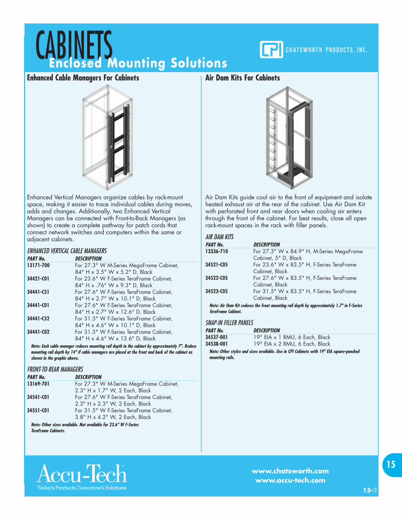
Enhanced Cable Managers For Cabinets
Enhanced Vertical Managers organize cables by rack-mountspace, making it easier to trace individual cables during moves,adds and changes. Additionally, two Enhanced VerticalManagers can be connected with Front-to-Back Managers (asshown) to create a complete pathway for patch cords thatconnect network switches and computers within the same oradjacent cabinets.
ENHANCED VERTICAL CABLE MANAGERSPART No. DESCRIPTION13171-700 For 27.3" W M-Series MegaFrame Cabinet,
84" H x 3.5" W x 5.2" D, Black34421-C01 For 23.6" W F-Series TeraFrame Cabinet,
84" H x .76" W x 9.3" D, Black34441-C51 For 27.6" W F-Series TeraFrame Cabinet,
84" H x 2.7" W x 10.1" D, Black34441-C01 For 27.6" W F-Series TeraFrame Cabinet,
84" H x 2.7" W x 12.6" D, Black34441-C52 For 31.5" W F-Series TeraFrame Cabinet,
84" H x 4.6" W x 10.1" D, Black34441-C02 For 31.5" W F-Series TeraFrame Cabinet,
84" H x 4.6" W x 12.6" D, BlackNote: Each cable manager reduces mounting rail depth in the cabinet by approximately 7". Reducemounting rail depth by 14" if cable managers are placed at the front and back of the cabinet asshown in the graphic above.
FRONT-TO-REAR MANAGERSPART No. DESCRIPTION13169-701 For 27.3" W M-Series MegaFrame Cabinet,
2.3" H x 1.7" W, 2 Each, Black34541-C01 For 27.6" W F-Series TeraFrame Cabinet,
2.3" H x 2.3" W, 2 Each, Black34551-C01 For 31.5" W F-Series TeraFrame Cabinet,
3.8" H x 4.2" W, 2 Each, BlackNote: Other sizes available. Not available for 23.6" W F-Series TeraFrame Cabinets.
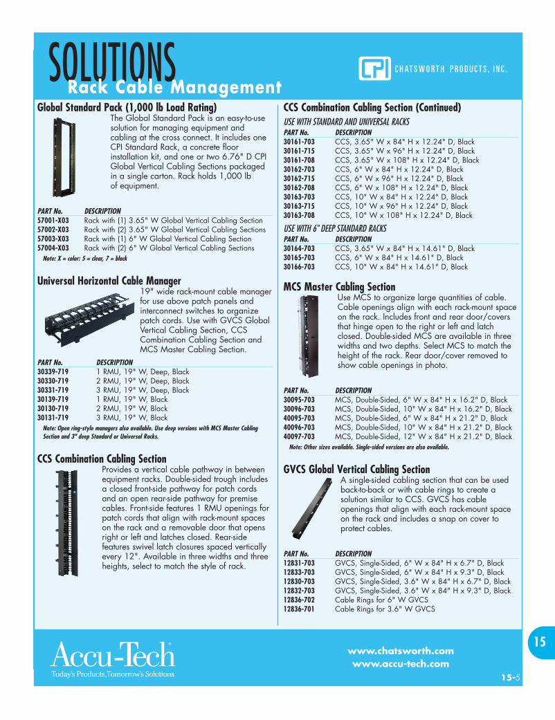
Air Dam Kits For Cabinets
Air Dam Kits guide cool air to the front of equipment and isolateheated exhaust air at the rear of the cabinet. Use Air Dam Kitwith perforated front and rear doors when cooling air entersthrough the front of the cabinet. For best results, close all openrack-mount spaces in the rack with filler panels.
AIR DAM KITSPART No. DESCRIPTION13336-710 For 27.3" W x 84.9" H, M-Series MegaFrame
Cabinet, 5" D, Black34521-C05 For 23.6" W x 83.5" H, F-Series TeraFrame
Cabinet, Black34522-C05 For 27.6" W x 83.5" H, F-Series TeraFrame
Cabinet, Black34523-C05 For 31.5" W x 83.5" H, F-Series TeraFrame
Cabinet, BlackNote: Air Dam Kit reduces the front mounting rail depth by approximately 1.7" in F-SeriesTeraFrame Cabinet.
SNAP-IN FILLER PANELSPART No. DESCRIPTION34537-001 19" EIA x 1 RMU, 6 Each, Black34538-001 19" EIA x 2 RMU, 6 Each, Black
Note: Other styles and sizes available. Use in CPI Cabinets with 19" EIA square-punchedmounting rails.
15--3
CABINETSEnclosed Mounting Solutions
www.chatsworth.comwww.accu-tech.com
15
7C0002X0_s15.qxd 4/29/08 3:09 PM Page 3

QuadraRack™ Server Frame (1,000 lb Load Rating)
QuadraRack™ 4-Post Frame (2,000 lb Load Rating)Fixed depth four-post racks that provide open front and rearsupport for large, heavy rack-mount equipment like modularnetwork switches. Choose threaded (4-Post Frame) or square-punched (Server Frame) equipment mounting holes. Cablemanagement accessories are available.PART No. DESCRIPTION50120-703 4-Post Frame, 19" W x 7' H x 29" D,
45 RMU, Black50120-715 4-Post Frame, 19" W x 8' H x 29" D,
45 RMU, Black50120-708 4-Post Frame, 19" W x 9' H x 29" D,
45 RMU, Black15053-703 Server Frame, 19" W x 7' H x 29" D,
45 RMU, Black
Adjustable QuadraRack™(2,000 lb Load Rating)
Adjustable ServerRack (2,000 lb Load Rating)
Adjustable depth four-post racks that provideopen front and rear support for large, heavyrack-mount equipment like modular networkswitches. The front and rear mountingchannels adjust in depth during assembly by.98" (25 mm) increments to match equipmentrequirements. Each rack has seven depthsettings. Choose threaded (QuadraRack™) orsquare-punched (ServerRack) equipmentmounting holes. Cable managementaccessories are available.
PART No. DESCRIPTION15215-703 QuadraRack, 19" W x 7' H, 15.75"-21.65" D,
45 RMU, Black15216-703 QuadraRack, 19" W x 7' H, 22.64"-28.54" D,
45 RMU, Black15217-703 QuadraRack, 19" W x 7' H, 29.53"-35.43"D,
45 RMU, Black15218-703 QuadraRack, 19"W x 7' H, 36.42"-42.32" D,
45 RMU, Black15211-703 ServerRack, 19" W x 7' H, 15.75"-21.65" D,
45 RMU, Black15212-703 ServerRack, 19" W x 7' H, 22.64"-28.54" D,
45 RMU, Black
Adjustable ServerRack (2,000 lb Load Rating) (Continued)PART No. DESCRIPTION15213-703 ServerRack, 19" W x 7' H, 29.53"-35.43" D,
45 RMU, Black15214-703 ServerRack, 19" W x 7' H, 36.42"-42.32" D,
45 RMU, BlackNote: Other sizes and colors available.
Standard Rack (1,000 lb Load Rating)
Universal Rack (1,500 lb Load Rating)Standard Rack and Universal Rack are two-post racks used to support patch panelsand other network equipment in datacenters, computer rooms and equipmentrooms. Aluminum racks bolt together andhave 3" or 6" deep C-shaped threadedmounting channels with marked andnumbered RMU spaces. Cablemanagement accessories are available.
PART No. DESCRIPTION48353-703 Universal Rack, 19" W x 84" H, 45 RMU, Black48353-715 Universal Rack, 19" W x 96" H, 51 RMU, Black48353-708 Universal Rack, 19" W x 108" H, 58 RMU, Black66353-703 6" Deep Standard Rack, 19" W x 84" H, 45 RMU, Black55053-703 Standard Rack, 19" W x 84" H, 45 RMU, Black55053-715 Standard Rack, 19" W x 96" H, 51 RMU, Black55053-708 Standard Rack, 19" W x 108" H, 58 RMU, Black40604-003 Installation Kit, Concrete Slab
Note: Other sizes and colors available. Racks are UL Listed.
Rack Shelves
PART No. DESCRIPTION40074-700 Single-Sided, 19" EIA x 3 RMU,
17.25" W x 14.8" D, 50 lb Load, Black
40108-719 Double-Sided, 19" EIA x 4 RMU, 17.75" W x 21.5" D, 100 lb Load, Black
11054-719 Double-Sided, 19" EIA x 5 RMU, 17.75" W x 25.8" D, 150 lb Load, Black
11164-719 Double-Sided, 19" EIA x 5 RMU, 17.75" W x 19.8" D, 200 lb Load, Black
40605-005 Mounting Screws, #12-24, 50 Each, Black
Note: Other styles, sizes and colors available. Use Double-Sided Shelves with 3" deep racks.Shelves are UL Listed.
15--4
www.chatsworth.comwww.accu-tech.com
SOLUTIONSOpen Mounting Solutions
15
7C0002X0_s15.qxd 4/29/08 3:09 PM Page 4
Global Standard Pack (1,000 lb Load Rating)The Global Standard Pack is an easy-to-usesolution for managing equipment andcabling at the cross connect. It includes oneCPI Standard Rack, a concrete floorinstallation kit, and one or two 6.76" D CPIGlobal Vertical Cabling Sections packagedin a single carton. Rack holds 1,000 lb of equipment.
PART No. DESCRIPTION57001-X03 Rack with (1) 3.65" W Global Vertical Cabling Section57002-X03 Rack with (2) 3.65" W Global Vertical Cabling Sections57003-X03 Rack with (1) 6" W Global Vertical Cabling Section57004-X03 Rack with (2) 6" W Global Vertical Cabling Sections
Note: X = color: 5 = clear, 7 = black
Universal Horizontal Cable Manager19" wide rack-mount cable managerfor use above patch panels andinterconnect switches to organizepatch cords. Use with GVCS GlobalVertical Cabling Section, CCSCombination Cabling Section andMCS Master Cabling Section.
PART No. DESCRIPTION30339-719 1 RMU, 19" W, Deep, Black30330-719 2 RMU, 19" W, Deep, Black30331-719 3 RMU, 19" W, Deep, Black30139-719 1 RMU, 19" W, Black30130-719 2 RMU, 19" W, Black30131-719 3 RMU, 19" W, Black
Note: Open ring-style managers also available. Use deep versions with MCS Master CablingSection and 3" deep Standard or Universal Racks.
CCS Combination Cabling SectionProvides a vertical cable pathway in betweenequipment racks. Double-sided trough includesa closed front-side pathway for patch cordsand an open rear-side pathway for premisecables. Front-side features 1 RMU openings forpatch cords that align with rack-mount spaceson the rack and a removable door that opensright or left and latches closed. Rear-sidefeatures swivel latch closures spaced verticallyevery 12". Available in three widths and threeheights, select to match the style of rack.
CCS Combination Cabling Section (Continued)USE WITH STANDARD AND UNIVERSAL RACKSPART No. DESCRIPTION30161-703 CCS, 3.65" W x 84" H x 12.24" D, Black30161-715 CCS, 3.65" W x 96" H x 12.24" D, Black30161-708 CCS, 3.65" W x 108" H x 12.24" D, Black30162-703 CCS, 6" W x 84" H x 12.24" D, Black30162-715 CCS, 6" W x 96" H x 12.24" D, Black30162-708 CCS, 6" W x 108" H x 12.24" D, Black30163-703 CCS, 10" W x 84" H x 12.24" D, Black30163-715 CCS, 10" W x 96" H x 12.24" D, Black30163-708 CCS, 10" W x 108" H x 12.24" D, Black
USE WITH 6" DEEP STANDARD RACKSPART No. DESCRIPTION30164-703 CCS, 3.65" W x 84" H x 14.61" D, Black30165-703 CCS, 6" W x 84" H x 14.61" D, Black30166-703 CCS, 10" W x 84" H x 14.61" D, Black
MCS Master Cabling SectionUse MCS to organize large quantities of cable.Cable openings align with each rack-mount spaceon the rack. Includes front and rear door/coversthat hinge open to the right or left and latchclosed. Double-sided MCS are available in threewidths and two depths. Select MCS to match theheight of the rack. Rear door/cover removed toshow cable openings in photo.
PART No. DESCRIPTION30095-703 MCS, Double-Sided, 6" W x 84" H x 16.2" D, Black30096-703 MCS, Double-Sided, 10" W x 84" H x 16.2" D, Black40095-703 MCS, Double-Sided, 6" W x 84" H x 21.2" D, Black40096-703 MCS, Double-Sided, 10" W x 84" H x 21.2" D, Black40097-703 MCS, Double-Sided, 12" W x 84" H x 21.2" D, Black
Note: Other sizes available. Single-sided versions are also available.
GVCS Global Vertical Cabling SectionA single-sided cabling section that can be usedback-to-back or with cable rings to create asolution similar to CCS. GVCS has cableopenings that align with each rack-mount spaceon the rack and includes a snap on cover toprotect cables.
PART No. DESCRIPTION12831-703 GVCS, Single-Sided, 6" W x 84" H x 6.7" D, Black12833-703 GVCS, Single-Sided, 6" W x 84" H x 9.3" D, Black12830-703 GVCS, Single-Sided, 3.6" W x 84" H x 6.7" D, Black12832-703 GVCS, Single-Sided, 3.6" W x 84" H x 9.3" D, Black12836-702 Cable Rings for 6" W GVCS12836-701 Cable Rings for 3.6" W GVCS
15--5
SOLUTIONSRack Cable Management
www.chatsworth.comwww.accu-tech.com
15
7C0002X0_s15.qxd 4/29/08 3:09 PM Page 5

CUBE-iT PLUS™ Cabinet System (200 lb Load Rating)
CUBE-iT Plus™ Cabinet System features a 5" deep rear panelwith eight cable entry ports (four top, four bottom). The body ofthe cabinet swings open for ease of access to the rear of rack-mounted equipment. CUBE-iT includes one pair of 19" widethreaded #12-24 equipment mounting rails that are adjustablefront-to-rear within the body of the cabinet and supports up to200 pounds of equipment. The front door and body are keyedalike, and the door is available with a solid metal or smokedplexiglass panel. Choose from three heights (24", 36", 48"), fourdepths (13", 18", 24", 30"), and two colors.PART No. DESCRIPTION13265-724 CUBE-iT PLUS, 24" W x 24" H x 13" D, 12 RMU,
Metal Door, Black13275-724 CUBE-iT PLUS, 24" W x 24" H x 13" D, 12 RMU,
Plexiglass Door, Black11890-724 CUBE-iT PLUS, 24" W x 24" H x 18" D, 12 RMU,
Metal Door, Black11901-724 CUBE-iT PLUS, 24" W x 24" H x 18" D, 12 RMU,
Plexiglass Door, Black11840-724 CUBE-iT PLUS, 24" W x 24" H x 24" D, 12 RMU,
Metal Door, Black11900-724 CUBE-iT PLUS, 24" W x 24" H x 24" D, 12 RMU,
Plexiglass Door, Black11996-724 CUBE-iT PLUS, 24" W x 24" H x 30" D, 12 RMU,
Metal Door, Black12419-724 CUBE-iT PLUS, 24" W x 24" H x 30" D, 12 RMU,
Plexiglass Door, BlackNote: Other sizes and colors available. Larger 1,000 lb capacity wall and floor-supported cabinetsare also available.
Standard Swing Gate Wall Racks (100 lb Load Rating)
Perfect for installing small quantities of equipment in confinedspaces, Swing Gate Racks are available in various sizes to meetyour networking needs. Easy to install, the frame attaches at 16"centers and the gate features spring loaded latches. Swing Gatehas C-shaped mounting rails with marked and numbered RMUspaces, threaded front and rear just like a freestanding rack, canopen to the right or left, and will support 100 pounds ofequipment in both the open and closed positions. Heavy DutySwing Gate Kit increases load bearing capacity to 150 lb.PART No. DESCRIPTION11790-718 Swing Gate, 19" W x 24.5" H x 18" D, 13 RMU, Black11791-718 Swing Gate, 19" W x 38.5" H x 18" D, 21 RMU, Black11807-718 Swing Gate, 19" W x 49.0" H x 18" D, 27 RMU, Black11792-718 Swing Gate, 19" W x 73.5" H x 18" D, 41 RMU, Black11799-001 Cable Rings, Set Of 6, Black12795-701 Heavy Duty Swing Gate Kit, Black
Note: Other sizes and colors available.
Fixed Wall-Mount Equipment Rack (200 lb Load Capacity)
Similar to the Standard Swing Gate Wall Rack but with fixedequipment mounting channels, Fixed Wall-Mount Equipment Rackdoubles the load bearing capacity to 200 pounds. Use it tosupport heavier switches and equipment. Some models can beordered with an enclosure.PART No. DESCRIPTION11960-718 Fixed, 19" W x 24.5" H x 18" D, 13 RMU, Black11961-718 Fixed, 19" W x 38.5" H x 18" D, 21 RMU, Black11962-718 Fixed, 19" W x 73.5" H x 18" D, 41 RMU, Black11799-001 Cable Rings, Set Of 6, Black
Note: Other sizes and colors available.
15--6
www.chatsworth.comwww.accu-tech.com
SOLUTIONSWall-Mount
15
7C0002X0_s15.qxd 4/29/08 3:09 PM Page 6
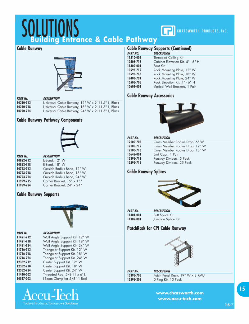
Cable Runway
PART No. DESCRIPTION10250-712 Universal Cable Runway, 12" W x 9'-11.5" L, Black10250-718 Universal Cable Runway, 18" W x 9'-11.5" L, Black10250-724 Universal Cable Runway, 24" W x 9'-11.5" L, Black
Cable Runway Pathway Components
PART No. DESCRIPTION10822-712 E-Bend, 12" W10822-718 E-Bend, 18" W10723-712 Outside Radius Bend, 12" W10723-718 Outside Radius Bend, 18" W10723-724 Outside Radius Bend, 24" W11959-715 Corner Bracket, 15" x 15"11959-724 Corner Bracket, 24" x 24"
Cable Runway Supports
PART No. DESCRIPTION11421-712 Wall Angle Support Kit, 12" W11421-718 Wall Angle Support Kit, 18" W11421-724 Wall Angle Support Kit, 24" W11746-712 Triangular Support Kit, 12" W11746-718 Triangular Support Kit, 18" W11746-724 Triangular Support Kit, 24" W12362-712 Center Support Kit, 12" W12362-718 Center Support Kit, 18" W12362-724 Center Support Kit, 24" W11440-002 Threaded Rod, 5/8-11 x 6' L10557-003 I-Beam Clamp for 5/8-11 Rod
Cable Runway Supports (Continued)PART NO. DESCRIPTION11310-003 Threaded Ceiling Kit10506-716 Cabinet Elevation Kit, 4" - 6" H11309-001 Foot Kit10595-712 Rack Mounting Plate, 12" W10595-718 Rack Mounting Plate, 18" W12408-724 Rack Mounting Plate, 24" W10506-706 Rack Elevation Kit, 4" - 6" H10608-001 Vertical Wall Brackets, 1 Pair
Cable Runway Accessories
PART No. DESCRIPTION12100-706 Cross Member Radius Drop, 6" W12100-712 Cross Member Radius Drop, 12" W12100-718 Cross Member Radius Drop, 18" W10642-001 End Caps, 1 Pair13392-711 Runway Dividers, 5 Pack13392-712 Runway Dividers, 25 Pack
Cable Runway Splices
PART No. DESCRIPTION11301-001 Butt Splice Kit11302-001 Junction Splice Kit
PatchRack for CPI Cable Runway
PART No. DESCRIPTION13395-708 Patch Panel Rack, 19" W x 8 RMU13396-208 D-Ring Kit, 10 Pack
15--7
SOLUTIONSBuilding Entrance & Cable Pathway
www.chatsworth.comwww.accu-tech.com
15
7C0002X0_s15.qxd 4/29/08 3:09 PM Page 7

FASTTRAC™ Cable Tray• Create point-to-point pathway• Use under raised floor or overhead• East to cut and form• Fast to install• Zinc electroplating allows use within
plenum space• UL classified as equipment grounding conductor
2" HEIGHTPART No. 5' LONG PART No. 10' LONG DESCRIPTION13340-004 13341-004 4" W x 2" H, Zinc13340-006 13341-006 6" W x 2" H, Zinc13340-008 13341-008 8" W x 2" H, Zinc13340-012 13341-012 12" W x 2" H, Zinc13340-016 13341-016 16" W x 2" H, Zinc13340-018 13341-018 18" W x 2" H, Zinc13340-020 13341-020 20" W x 2" H, Zinc13340-024 13341-024 24" W x 2" H, Zinc
4" HEIGHTPART No. 5' LONG PART No. 10' LONG DESCRIPTION13342-004 13343-004 4" W x 4" H, Zinc13342-006 13343-006 6" W x 4" H, Zinc13342-008 13343-008 8" W x 4" H, Zinc13342-012 13343-012 12" W x 4" H, Zinc13342-016 13343-016 16" W x 4" H, Zinc13342-018 13343-018 18" W x 4" H, Zinc13342-020 13343-020 20" W x 4" H, Zinc13342-024 13343-024 24" W x 4" H, Zinc
6" HEIGHTPART No. 5' LONG PART No. 10' LONG DESCRIPTION13342-008 13343-008 8" W x 6" H, Zinc13342-012 13343-012 12" W x 6" H, Zinc13342-016 13343-016 16" W x 6" H, Zinc13342-018 13343-018 18" W x 6" H, Zinc13342-020 13343-020 20" W x 6" H, Zinc13342-024 13343-024 24" W x 6" H, Zinc
15--8
www.chatsworth.comwww.accu-tech.com
SOLUTIONBuilding Entrance & Cable Pathway
15
SUPPORTS AND FASTENERSPART No. DESCRIPTION13354-004 Center Support Bracket, 4" W, for 3/8" Rod13354-008 Center Support Bracket, 6"-8" W, for 3/8" Rod13354-012 Center Support Bracket, 12" W, for 3/8" Rod13354-016 Center Support Bracket, 16" W, for 3/8" Rod13354-020 Center Support Bracket, 18"-20" W, for 3/8" Rod13354-024 Center Support Bracket, 24" W, for 3/8" Rod13357-008 Intersect Support Plate, 4"-8" W13357-016 Intersect Support Plate, 12"-16" W13357-024 Intersect Support Plate, 20"-24" W13356-004 Triangle Support Bracket, 4" W13356-008 Triangle Support Bracket, 6"-8" W13356-012 Triangle Support Bracket, 12" W13356-016 Triangle Support Bracket, 16" W13356-020 Triangle Support Bracket, 18"-20" W13356-024 Triangle Support Bracket, 24" W
PART No. DESCRIPTION13387-008 Wall Termination Support, 4"-8" W13387-016 Wall Termination Support, 12"-16" W13387-024 Wall Termination Support, 18"-24" W13350-020 Under Floor Support Bracket, 20" W x 3" H13351-020 Under Floor Support Bracket, 20" W x 6" H13352-020 Under Floor Support Bracket, 20" W x 9" H13367-001 Wire Shear13369-001 Wire Bender13368-001 Cable Roller13361-001 Ground Washer Kit, 50 Pack (Use Over Supports)13374-001 Pedestal Clamp13364-001 Washer Splice Kit, 50 Pack (Use Mid-span)13365-001 Splice Bars, 50 Pack (Use With Trays 12" W And Over)
Note: Other options available.
7C0002X0_s15.qxd 4/29/08 3:09 PM Page 8

15--9
SOLUTIONZone and Wireless Enclosures
www.chatsworth.comwww.accu-tech.com
15
2' x 4' Ceiling Enclosures (85 lb Load Rating)2' x 4' Ceiling Enclosures create a space within the drop ceiling for consolidation points oractive cross connects. Ceiling enclosures can be used within an air handling space. A fullyhinged access door and internal brackets provide support for 110-style blocks, patch panelsor active equipment. All models have four cable access ports that include foam sealing kits.The active equipment model includes an electrical junction box and internal fan.PART No. DESCRIPTIONA1224-LP For 110-blocks, 2 x 300-pairA1224-PP For Patch Panels, 2 x 4 RMUA1224-HR For Active Equipment, 2 x 4 RMU
Ceiling-Mounted Wireless EnclosuresWireless networks are becoming more common in office spaces. Wireless enclosures createspaces within the drop ceiling for wireless access points providing added physical securityfor the access points and the associated network connections. Wireless enclosures are easyto install and can be used in air handling spaces to support access points up to 10" W x8" D x 2" H. Antennas pass through holes on the interchangeable faceplate in the accessdoor providing maximum coverage of the workspace below. The new Universal Faceplateworks with most access points providing a 10" L x 1" W slot for antennas. Also availablewith an electrical junction box.PART No. DESCRIPTIONAAT-CAP-UNI-KIT 10" Enclosure With Universal FaceplateAAT-CAP-00-KIT 10" Enclosure With Blank FaceplateAAT-CAP-35-KIT 10" Enclosure With CISCO® 350 FaceplateAAT-CAP-12-KIT 10" Enclosure With CISCO® 1200 Faceplate
Note: Other styles and sizes available.
ThinLine™ II Wall-Mount CabinetThinLine™ II Wall-Mount Cabinet is a low profile wall-mount cabinet that projects less than12" from the wall. Equipment hangs vertically within the cabinet on adjustable mountingrails. ThinLine II provides an easy way to secure a consolidation point or a small cross-connect. ThinLine II includes an internal 2" x 4" junction box for a power outlet and willsupport 100 pounds of equipment. There are knockouts for 3/4" and 1/2" conduit andairflow louvers along the sides. The door has a keyed lock and can be hinged to open fromthe right or left side. An internal ventilation fan is available as an accessory.PART No. DESCRIPTION13050-711 Cabinet, 26" W x 26" H x 5" D, 19" EIA x 2 RMU, Black13050-712 Cabinet, 26" W x 26" H x 8.5" D, 19" EIA x 4 RMU, Black13050-713 Cabinet, 26" W x 26" H x 12" D, 19" EIA x 6 RMU, Black13051-001 Fan For 4 RMU Or 6 RMU Cabinet13051-002 Fan For 2 RMU Cabinet
Note: Other sizes and colors available.
7C0002X0_s15.qxd 4/29/08 3:09 PM Page 9