inf 05 safe erection of precast flooring - code2001
TRANSCRIPT

PRECAST FLOORING FEDERATIONC O D E O F P R A C T I C Efor the safe erection of precast concrete flooringand associated components
APRIL 2001
UNICLASS A4:C506:L342:P225

Published and distributed by the Precast Flooring Federation
60 Charles Street, Leicester LE1 1FBTelephone 0116 253 6161 Fax 0116 251 4568
Website www.pff.org.ukA product association of the British Precast Concrete Federation
This edition published 2001
A catalogue record for this book is available from the British Library
ISBN: 0 9536773 1 1
Previous Edition published 1997, ISBN 0 9500347 3 8
No part of this publication may be reproduced, stored in a retrieval system or transmittedin any form or by any means, electronic, mechanical, photocopying or otherwise,without prior written permission from the Secretary, Precast Flooring Federation,
60 Charles Street, Leicester LE1 1FB
Every effort has been made to ensure that the statements made and advice given providea safe and accurate guide; however, no liability or responsibility of any kind (including
liability for negligence) can be accepted in this respect by the publishers or the authors.
PFF APRIL 2001

PFF APRIL 2001

FOREWORD
The aim of this Code is to improve safety on sites where precast flooring products andassociated components are being used. As an industry we are committed to ensuring aconsistently high standard and common approach to Health and Safety, providing ouremployees and customers alike with clear unambiguous information about our systems ofwork and attendances required. This Code can therefore be considered to be ‘IndustryBest Practice’. Because it is monitored and updated it can be relied upon to achieve thesestandards.
Since the last revision of this Code of Practice in 1997 there have been many changes toHealth and Safety Regulations, guidance and industry practice, which has necessitated thislatest revision. The Health and Safety Executive now rely on organisations such as thePrecast Flooring Federation to develop and provide recommendations for best practice andsafe systems of work for industry.
The Precast Flooring Federation Health and Safety Committee, made up of representativesfrom the major suppliers of precast flooring products, specialist erection companies andother associated companies have attempted to deal with the latest regulations in a practicalmanner so that you will find the Code broken down into various sections for easy referenceand in a logical sequence which is easily accessible.
Installing precast flooring components is a high-risk activity, involving the use of heavyplant, such as cranes, and personnel working at height. The Code is therefore used as thecore material for the training of Erectors, Foremen and Supervisors to ensure that thisoperation is only carried out by skilled, competent personnel.
The Code is intended for use by all those involved in the design, specification, use anderection of these precast flooring products and as such we recommend that the followingread this Code: -
• Designers who are considering using these products, and planning Supervisors.
• Contractors, Principal Contractors and Clients who intend to use these products onsite.
• Those involved in the planning of erection work.
• All who are engaged in the erection of precast flooring products and associatedcomponents.
The Precast Flooring Federation gratefully acknowledges the help and guidance providedby the Health and Safety Executive in the preparation of this Code.
It is only by working together, using highly trained and competent personnel that we canachieve high standards of health and safety which can continually improve.
D J Burgess FRSH, MIOSH, MIIRSM
Chairman, Precast Flooring Federation Health and Safety Committee
PFF APRIL 2001
i

CODE OF PRACTICE DRAFTING COMMITTEE
D Burgess (Chairman) Hanson Birchwood.
C J Budge (Secretary) British Precast Concrete Federation Ltd.
M Shearon Health & Safety Executive.
M Yates Bison Concrete Products Ltd.
P Hales Bison Concrete Products Ltd.
S Clark Marshalls Flooring Ltd.
N Clark Marshalls Flooring Ltd.
M J Milbank Milbank Floors Ltd.
J Neville Tarmac Topfloor Ltd.
N McCulloch Breton Precast Ltd.
P Darrington Graceland Fixing Ltd.
A Carden Shire Precast Erection Ltd.
M C Padkin Ainscough Group Ltd.
S Cooper Hewden Crane Hire Ltd.
PFF APRIL 2001
ii

CONTENTS
Reference Title Page Number
DEFINITIONS viREFERENCES viii
SECTION 1: MANAGEMENT OF HEALTH AND SAFETY 1
1.1 Management of Health & Safety at Work1.2 Manual Handling Operations1.3 Personal Protective Equipment at Work1.4 Provision and Use of Work Equipment1.5 Workplace Health, Safety and Welfare1.6 Control of Substances Hazardous to Health (COSHH)1.7 Noise at Work
SECTION 2: SAFE WORKING METHOD STATEMENTS 11
2.1 Introduction2.2 Content of Safe Working Method Statements2.3 Communication of Safe Working Method Statements2.4 Additions to the Safe Working Method Statements2.5 Special Considerations
SECTION 3: TRAINING AND CERTIFICATION 15
3.1 Introduction3.2 Scope3.3 Responsibility3.4 General Procedure3.5 Training3.6 Audits and Verification of Training Standards3.7 Application for the PFF Training Achievement Card
SECTION 4: DESIGN STAGE CONSIDERATIONS 19
4.1 The Existing Environment4.2 Design and Planning4.3 Construction Phase4.4 Health and Safety File4.5 Lifting, Placing and Safe Handling of Units4.6 Imposed Loads During Installation4.7 Stability of Supporting Structures During Installation4.8 General
SECTION 5: GENERAL CONTRACTOR’S/PRINCIPAL CONTRACTORS 27RESPONSIBILITIES
5.1 Attendances5.2 Prevention of Damage to Precast Units
PFF APRIL 2001
iii

Reference Title Page Number
SECTION 6: COMPANY REPRESENTATIVE’S ROLE 29
6.1 Agreed Sequence of Installation6.2 Method of Lifting6.3 Site Access6.4 Attendances Liaison6.5 Supervision of Installation
SECTION 7: FOREMAN’S ROLE 31
7.1 Working to the Safe Working Method Statement and Sequence of Work7.2 Checking of Attendances7.3 Supervision of Installation
SECTION 8: TRANSPORTATION OF COMPONENTS AND ACCESS TO SITE 33
8.1 The Stacking and Making Secure of Loads8.2 Loading Sequence8.3 Site Access8.4 Unloading
SECTION 9: ON-SITE STORAGE OF COMPONENTS 35
9.1 Storage at Ground Level9.2 Storage above Ground Level
SECTION 10: CONTROL OF LIFTING OPERATIONS AND SAFE USE OF 37CRANES, FORK LIFTS AND OTHER LIFTING EQUIPMENT
10.1 Introduction10.2 Management of the Lifting Operation10.3 Control of the Lifting Operation10.4 Documentation - Certificates, Records and Registers10.5 Start of Lifting Operation10.6 Tower Cranes10.7 Use of On-Site Equipment10.8 Weather Restrictions10.9 Patent Lifting Devices10.10 Chain Slings10.11 Multiple Leg Slings10.12 Lifting Forks, Grabs and Block Handling Devices10.13 Lift Trucks
SECTION 11: MOVEMENT OF UNITS BY OTHER MEANS 57
11.1 Barring 11.2 Jacking 11.3 Bogies11.4 Chain Blocks, Tirfors etc. 11.5 Winches Poles and Beams
PFF APRIL 2001
iv

Reference Title Page Number
SECTION 12: ADDITIONAL ON SITE WORKS 61
12.1 Temporary Structural Support12.2 Propping12.3 Insitu Concrete12.4 Concrete Screeds/Toppings12.5 Grouting12.6 Forming of Holes
SECTION 13: ACCESS TO WORKING AREA, WORK AT HEIGHT, 65PROTECTION AGAINST FALLS
13.1 General Principles for Preventing Falls13.2 Safe Access to Working Area13.3 General Systems of Protection13.4 Hierarchy for Fall Protection, Prevention and Fall Arrest13.5 Safety Nets13.6 Air Bags13.7 Working Platforms13.8 Decking Systems13.9 Staging13.10 Access Platforms, Mobile Towers and Other Mobile Equipment13.11 Fall Arrest equipment13.12 Other Systems
SECTION 14: PROTECTION OF THIRD PARTIES 77
14.1 Other Trades or Persons on Site14.2 Members of the Public
SECTION 15: SUBCONTRACTOR & SUPPLIER APPROVAL 79
15.1 Introduction15.2 Assessment Application15.3 Selection Criteria for Installation Sub-contractors (Precast Concrete Installers)15.4 Selection Criteria for Suppliers/sub-contractors of Fall Protection Equipment15.5 Approved Suppliers/Sub-contractors List15.6 Records
APPENDICES
A Supplier/Sub-Contractor Assessment Form 83B Standard Health, Safety and Welfare Attendances 85C Construction Design and Management Regulations 87
PFF APRIL 2001
v

DEFINITIONS
Most of the terms used in this document are in common use. However, the followingdefinitions are intended to remove any ambiguity:
APPOINTED PERSON: The person employed by the ‘Company’ to have overall controlof the lifting operation and to act on behalf of the ‘Company’. The Appointed Person musthave adequate training and experience to ensure the implementation of a safe system ofwork.
AS INSTALLED DRAWING: The layout drawings confirming actually ‘as installed’positions of precast flooring/component positions, issued for the client’s safety file.
ATTENDANCES: The standard PFF Health, Safety & Welfare Attendances, a copy of whichis included as an Appendix to this Code.
BUILDING DESIGNER: The designer of the building or structure receiving the precastflooring components.
CERTIFICATED: Having been trained and qualified to fulfil a particular role. Generally,holding a valid licence/certificate of training gained by attending a recognised course ofinstruction for the task in question.
COMPANY: The precast concrete sub-contractor engaged in the erection of flooring orprecast components.
COMPANY REPRESENTATIVE: A travelling Supervisor/Contracts Manager in theInstallation Company’s employ with a responsibility for a number of contracts. A competentperson trained to assess all health, safety and welfare arrangements in relation to companyoperations.
COMPONENT: Any member, article, or item, which comprises of precast concrete orancillary metalwork.
CONTRACTOR: The ‘Contractor’ shall mean the precast concrete sub-contractor’s client.
CONTRACTOR’S SITE REPRESENTATIVE: The person in charge of the day to dayrunning of a particular site or project, i.e., Site Manager, Site Agent, General Foreman,Project/Contracts Manager.
CRANE OPERATOR: A competent and trained person responsible for the correctoperation of the crane in accordance with the Manufacturer’s Operating Instructions, theSafe Working Method Statement and directions from the nominated Slinger/Signaller.
CRANE SUPERVISOR: The person designated by the ‘APPOINTED PERSON’ to supervisethe lifting operations, where the APPOINTED PERSON has deemed the operations as basicor standard, as defined by BS 7121-3:2000 Section 4.8.
DESIGNER: The person or persons in the Company’s employ who actually produces,specifications, estimates, drawings, details, designs or calculations for a particular contract,or a particular type of company product. (This is not the Building Designer).
PFF APRIL 2001
vi

ERECTOR: A person who, after suitable training, is competent to carry out all functionsof Slinger and Signaller, as well as to hoist, place and secure precast concrete sections,including all plumbing/levelling and lining up, with the ability and training to work safely.Has a general understanding of structural stability issues. An ERECTOR may be employedby the Company, a specialist erection company or be self-employed.
FLOORING: The precast concrete components that form the structural element of a floorand may include associated precast components.
FOREMAN: The person in charge of the precast erection team, actually undertaking thesite work for the Company
GROUTING: Filling of voids between adjacent units to stabilise the floor and/or form astructural connection between units.
HOLLOWCORE: Precast Concrete Flooring System, which for the purposes of thisdocument is deemed to include terms such as ‘wideslab’, ‘solid planks’ etc.
PLANNING SUPERVISOR: The individual or organisation appointed by the client as thePlanning Supervisor under the Construction (Design and Management) Regulations 1994,and responsible for ensuring co-operation between all designers.
PRINCIPAL CONTRACTOR: The contractor with overall responsibility for theConstruction phase of the project. The Principal Contractor may either employ the PrecastConcrete Sub-Contractor (Company) directly or they may employ a Contractor, who in turnemploys the Precast Concrete Sub-contractor.
SIGNALLER (BANKSMAN): The person with responsibilities, after suitable certificatedtraining, for directing the safe movement of a load attached to a crane, and for themovement of the crane on site.
SLINGER: A person who has been suitably trained in the proper selection of lifting tackle,the slinging of loads to the crane attachment, taking into account the capabilities of thecrane employed.
WORK AREA: The area on a site or building where precast flooring/components arebeing erected. This includes the area covered by the radius of a crane from lifting off a lorry(or stack) to the final position.
WORKING DRAWINGS: The layout drawings, section and details, produced by the‘Designer’ and issued for client approval, production and erection purposes.
PFF APRIL 2001
vii

REFERENCES
Health & Safety at Work etc. Act. 1974
The Management of Health & Safety at Work Regulations 1999
The Highly Flammable Liquids and Liquefied Petroleum Gases Regulations 1972The Health & Safety (First Aid) Regulations 1981The Noise at Work Regulations 1989The Electricity at Work Regulations 1989The Personal Protective Equipment at Work Regulations 1992The Provision and Use of Work Equipment Regulations 1998The Lifting Operations and Lifting Equipment Regulations 1998The Manual Handling Operations Regulations 1992The Control of Substances Hazardous to Health Regulations 1999The Construction (Design & Management) Regulations 1994The Reporting of Injuries, Diseases and Dangerous Occurrences Regulations 1995The Construction (Health, Safety & Welfare) Regulations 1996
The following Health and Safety Executive Guidance Notes are also relevant:
GS 6 Avoidance of Danger from Overhead Electrical LinesHS(G) 141 Electrical Safety On Construction SitesHS(G) 144 The Safe Use of Vehicles on Construction SitesHS(G) 149 Backs For The Future – Safe Manual Handling In ConstructionHS (G) 150 Health and Safety in Construction
The following Construction Industry Advisory Committee Documents are also relevant: -
Designing for Health and Safety in Construction (A Guide for Designers on theConstruction (Design and Management) Regulations 1994
A Guide to Managing Health and Safety in Construction
Guidance notes are issued on a continuing basis and users of this Code of Practice shouldacquaint themselves with the latest updates and revisions.
BS 5975 Code of Practice for FalseworkBS 7121 Code of Practice for Safe Use of Cranes Parts 1, 2 and 3.BS 5628 Code of Practice for Use of MasonryBS 8110 Structural Use of Concrete
Part 1: 1997 : Code of Practice for design and construction
CIRIA Special Publication SP 130: Site Safety HandbookCIRIA Special Publication SP 131: Crane Stability on SiteCIRIA Report 166: CDM Regulations - Work Sector Guidance for Designers
PFF APRIL 2001
viii

1. MANAGEMENT OF HEALTH & SAFETY
The Health & Safety at Work Act places several general duties on employers, employees andothers. Regulations are made under Section 16 of the Health & Safety At Work etc. Act 1974.The Regulations referred to in the introductory notes below are a legal requirement andmust be adhered to at all times. For more information, refer to the documents themselves,listed in the References, and where necessary obtain competent, professional advice onsafety matters.
1.1 Management of Health & Safety at Work Regulations 1999 and ApprovedCode of Practice
Regulation 3 (1) of the Management of Health & Safety at Work Regulations 1999 requiresall employers and self-employed to assess the risk to the health and safety of workers andany others who may be affected by the work carried out.
Assessments will help to identify all the protective and preventative measures that need tobe taken to comply with legislation to ensure that health and safety standards aremaintained. Guidance on the procedures for risk assessment can be found in the ApprovedCode of Practice under the Management of Health & Safety at Work Regulations 1999,which includes advice on the selection of preventative and protective measures.
Before an assessment of risk can be made it is important to understand the terms used, thetwo most important being: -
Hazard - is something with the potential to cause harm,
Risk - expresses the likelihood that the harm from a particular hazard is realised.
Most employers will be capable of making the risk assessment themselves using expertisewithin their own organisations, however, where there are complex hazards or equipment,it may need to be done in conjunction with the help of external health and safety advisors,appointed under Regulation 7 of the Management of Health & Safety at Work Regulations1999.
Assessment of the risk must take account of the severity of the risk, the number of peopleexposed and the possible consequences.
The key actions to be taken can be summarised as below: -
a These regulations require an employer to make a suitable assessment of the risks tothe health and safety of employees and others who may be exposed to those risks.This includes contractors or temporary staff engaged for specific work.
b Where the risk is considered to be significant, the assessment must be recorded inwriting and identify those personnel especially at risk.
c Risk assessments must be regularly reviewed and altered if they are no longer validor circumstances/conditions have changed significantly.
d A nominated competent person (or persons if required) must be appointed to assistin complying with the regulations.
e Emergency procedures must be established, and competent people nominated toimplement them.
PFF APRIL 2001
1

f Information must be provided to the employees on the risks identified, the controlmeasures to be taken, the names of the competent persons and information on therisks identified when employers share work areas.
g Training must be given to employees in respect of the duties placed upon them bythe regulations, at induction when first employed, when transferred, or if the jobchanges. This training must be updated and repeated periodically to take accountof any changes.
PFF APRIL 2001
elbaTgnitaRksiR
ytireveS
1 2 3 4 5
1 1 2 3 4 5
2 2 4 6 8 01
3 3 6 9 21 51
4 4 8 21 61 02
5 5 01 51 02 52
deriuqernoitcaoN=1
snoitulosevisnepxenielpmisredisnoC=4,3,2
ksirehtecuderotedamebdluohsstroffE=6,5
ksirehtecuderotedamebtsumtroffeelbaredisnoC=01,9,8
dnaksirehtecuderotderiuqernoitcatnegrU=61,51,21osodotelbaliavaedamebtsumsecruoserelbaredisnoc
fosseldragerpotstsumrotratstontsumnoitarepoehT=52,02yltnacifingisdecuderneebsahksirehtlitnutsoclaicnanifyna
Lik
elih
oo
d
doohilekiLytireveS
WOL MUIDEM HGIH
WOL WOL MUIDEM HGIH
MUIDEM MUIDEM MUIDEM HGIH
HGIH HGIH HGIH HGIHYREV
An alternative method using high, medium and low ratings is used as follows: -
2

In addition employees have certain duties under the regulations: -
h To make full and proper use of anything provided by the employer in accordancewith the training given. This includes safety equipment, machinery, substances,means of transport etc.
i Employees must also inform the employer (or nominated persons) of any dangerouswork situation or any matter relating to the employer’s health & safety arrangements.
1.1.1 General Procedure for Risk Assessment
1. Identify the hazards and activities
2. Assess the risks i.e., the nature and extent of the risks
3. Assess existing control measures or precautions for adequacy, are any furthermeasures needed?
4. Check for compliance with other legal requirements
5. Record the findings and arrangements and inform as required.
1.2 Manual Handling Operations
1.2.1 Introduction
The Manual Handling Operations Regulations 1992 came into force on 1st January 1993and are made under the Health & Safety at Work etc. Act 1974.
These Regulations must not be considered in isolation, but should be read in conjunctionwith Regulation 3 (1) of the Management of Health & Safety at Work Regulations 1999which requires employers to make a suitable and sufficient assessment of the risks to the tothe Health & Safety of their employees while at work.
1.2.2 Manual Handling Assessments
Hollowcore flooring is too heavy to lift manually and therefore an assessment coveringmanoeuvring and placement should be carried out.
Handling of concrete floor elements and infill blocks can give rise to a wide range ofinjuries, including serious injuries where damage may be gradual and progressive over asubstantial period of time.
To reduce the risk of an injury, floor design, site conditions and the way the work isorganised must be properly planned. This guidance contains practical advice on thesematters and will help designers and specifiers, those managing work on site and those whohandle beams and blocks on site.
Individual companies must make their own assessment in respect of the requirements fortheir own products and employees, in compliance with these Regulations. Whereassessments indicate a possibility of risks to employees from the manual handling of loadsthe following requirements of the Regulations must be followed:
PFF APRIL 2001
3

1 Avoid hazardous manual handling operations so far as is reasonably practicable. Thismay be done by redesigning the task to avoid moving the load or by automating ormechanising the process.
2 Make a suitable and sufficient assessment of any hazardous manual handlingoperations that cannot be avoided.
3 Reduce the risk of injury from those operations so far as is reasonably practicable.Particular consideration should be given to the provision of mechanical assistancebut where this is not reasonably practical then other improvements to the task, theload and the working environment should be explored.
Risk assessments have been carried out on typical contracts including ground floor and firstfloor applications. The assessments revealed that the main risks are: -
1 a) heavy loads and poor posture leading to excessive stress and straincausing injury to muscles and tendons particularly as the handlinginvolves bending, twisting, stooping or other difficult postures;
b) slips, trips and falls, particularly when carrying loads across floor beamswhich have been laid out to receive infill blocks and which necessarily
have gaps between them; and falls from upper floor levels whereinsufficient edge protection is provided;
c) Sharp edges causing cuts and abrasions to the skin.
2. With floor beam and infill concrete block handling the risk of injury is largelydetermined by the weight of individual items - the longer the floor beam the heavierits weight; the heavier the concrete block, the higher the risk of injury.
3. Where because of site conditions, T-beams cannot be positioned by crane or othermechanical handling equipment, manual handling and carrying risks are greatlyincreased. In such cases the route between the delivery position of the beams andthe erection location must be carefully planned and prepared to minimise the riskscreated by obstacles or tripping hazards.
4. The final positioning of floor beams in ground floor situations usually permits theerector to stand below the level of the floor beam and although the movementrequired is not excessive, considerable stooping is required to grasp the load and therisk of injury is high.
5. The final positioning of floor beams in upper floors typically requires the erector tostand on the same level as that on which the floor beam is resting. In this situationthe erector is required to grasp the load at or below foot level and the risk of injuryis high.
6. When “blocking-out”, packs of blocks are placed onto pre-positioned floor beams.The blocks are then carried from the cube and laid into the floor beam recess belowfoot level.
PFF APRIL 2001
4
1.2.3 Precautions
1. Designers and specifiers should where possible minimise the length of floor beamsto keep weight as low as reasonably practicable. Typically, 150 mm floor T-beamsweigh 32kg/metre and 225 mm floor T-beams weigh 55kg/metre.
Infill blocks should be of the lightest type available within the specification requiredfor the properties of the finished floor.
2. Project Planners, Designers and Contractors should ensure that the items listedbelow are taken into account when planning the work and when devising safesystems of work. Contractors should also give instruction and exercise supervisionto ensure that workers follow these plans and systems of work.
1.2.4 The Task
The following advisory notes should be considered when writing the Company proceduresfor the handling and erecting of floor beams and infill blocks: -
Plan to off load floor beams from the delivery lorry directly onto the walls on which theywill be finally positioned using a crane or other suitable mechanical handling equipment.
Wherever reasonably practicable provide craneage of sufficient capacity to cover the wholeof the floor area being laid.
Where positioning of T-beams and blocks cannot be achieved using a crane or othermechanical handling device, trolleys or bogies should be used to convey the items. Theroute must be prepared and be clear of obstacles or tripping hazards.
Operatives should adjust their work rate to permit short breaks to be taken at regularintervals and should rotate their duties.
Ensure sufficient time is allowed for the compilation of the work allocation without theneed for undue haste.
Packs of infill blocks should be positioned as close as possible to the laying positions.
Blocks should never be thrown from one person to another.
1.2.5 The Working Environment
Prepare roads and routes around the site in advance of the delivery of the beams and blocksand if they are not to be off loaded into their laying position, prepare suitable stacking areas.
In areas where the beams and blocks are carried or handled, keep the site clear of obstacles andtripping hazards. Uneven, slippery or unstable ground conditions increase the risk of injury.
1.2.6 Training
Erectors must be given information and training on manual handling risks, their preventionand the systems of work to be used on that site to ensure safe manual handling of beamsand blocks. Suitable training will also be necessary for designers, specifiers and thosemanaging contracts.
PFF APRIL 2001
5

1.2.7 Individual Capability
Particular consideration must be given to employees who are known to have a history ofback trouble, hernia or other health problems which could affect their manual handlingcapability.
1.2.8 Health Surveillance
Employers should conduct appropriate health surveillance in order to identify at an earlystage any indications that the employee is suffering injury due to the manual handling of T-beams and blocks, thereby enabling further harm to be prevented.
1.2.9 Personal Protective Equipment
When handling beams and blocks the normal protective equipment needed for use onbuilding sites should be provided by employers and worn by individual workers; inparticular, safety helmets, safety footwear with protective toe-caps and abrasion resistantgloves.
1.3 Personal Protective Equipment At Work
1.3.1 Introduction
The Personal Protective Equipment at Work Regulations 1992 were implemented on 1January 1993 and are made under the Health & Safety at Work etc. Act 1974. TheRegulations are based on a European Community (EC) Directive requiring similar basiclaws throughout the community on the use of personal protective equipment (PPE) in theWork Place.
The Health & Safety Executive (HSE) prepared specific guidance on the regulations afterwidespread consultation with industry. Readers should refer to the guidance on theregulations produced by the Health & Safety Executive.
The document contains advice on the selection of PPE and also considers the different typesof PPE available and identifies some of the processes and activities which may require PPEto be worn.
1.3.2 Working Clothes and Personal Protective Equipment
The Personal Protective Equipment at Work Regulations (PPE Regs.) require the Employerto provide suitable personal protective equipment (PPE) necessary for the protection ofoperatives engaged in the erection of precast concrete flooring. The requirements forpersonal protective equipment must be identified on the General Risk Assessment.
All operatives, irrespective of the nature of particular site conditions, must be provided withpersonal protective equipment to meet general needs, e.g., protective footwear, gloves,weatherproof clothing and suitable head protection. All PPE must be properly stored andmaintained in accordance with manufacturers’ recommendations.
The distribution and quality of such equipment are matters of individual company policy.However, all protective equipment or clothing must carry the CE Mark, identifying theproduct as having passed certain European Standards, or be of a standard at least equal tothat set by the appropriate British Standard.
PFF APRIL 2001
6

Wherever possible the Company should consider the views and comments received fromtheir operatives when deciding upon particular types of equipment. The physical stature ofoperatives should be matched as closely as is practicable by any equipment. Personalprotective equipment must also be compatible if worn with other PPE, e.g. hearingprotection worn with head protection.
The Company must ensure that all protective clothing and equipment is fit for use andshould apply all necessary measures to ensure that their employees are using such items inproper manner. Operatives issued with such equipment have a duty under the Health andSafety at Work Act 1974 to use and look after it. The Company must ensure that operativesreceive adequate instruction regarding the proper use and storage of protective equipmentand clothing.
On certain sites the conditions or method of working will necessitate the use of specialprotective clothing and equipment. Certain items such as eye protection, respiratoryprotection, ear protection and safety harnesses should be carried by the erection team at alltimes and used as the need arises or made available to the erection team prior to thecommencement of work. The use of specific protective equipment, e.g., safety harnesses,must be identified in the method statement.
The Erectors should conduct regular inspections of all equipment and clothing and anyitems found to be missing or defective should be notified to the Company for immediatereplacement or repair.
1.4 Provision And Use Of Work Equipment Regulations 1998
1.4.1 General
The Provision and Use of Work Equipment Regulations 1998 (PUWER) lay down importanthealth & safety regulation regarding work equipment. The primary objective of PUWER isto ensure the provision of safe work equipment and its safe use. The PUWER Regulations1998 make more explicit the general duties on employers, the self-employed and personsin control to provide safe plant and equipment. The PUWER Regulations 1998 must not beconsidered in isolation, in particular, they need to be read in conjunction with theManagement of Health & Safety at Work Regulations 1999.
Although the prime duty for ensuring health & safety rests with employers, employees alsohave legal duties, particularly under Sections 7 and 8 of the Health & Safety at Work etc. Act1974. These duties have been supplemented by Regulation 14 of the Management of Health& Safety at Work Regulations 1999 which require that employees must use correctly allwork items provided by their employer in accordance with the training and instructionsthey received to enable them to use the items safely. This is particularly relevant toemployees using work equipment.
1.4.2. Vibration and Vibrating Tools
Hand Arm Vibration is vibration transmitted from work processes into workers' hands andarms. It can typically be caused by operating hand-held power tools such as portable disccutters.
Regular and frequent exposure to high levels of vibration can lead to permanent injury.This is most likely when contact with a vibrating tool or process is a regular part of aperson's job. Occasional exposure is unlikely to cause injury, although it should be avoidedby people with medical conditions such as Raynaud's Disease.
PFF APRIL 2001
7

Health and safety law requires the Company to assess the risk to the health of employees,plan for its control and manage the risk. This will include provision of suitable equipment,correct maintenance of equipment and giving employees information and training onhealth risks and safe use of the equipment.
Recognition and Control of Risk
The documentation supplied by the equipment manufacturer should warn of risks fromvibration. Regular use of hand-held power tools may give rise to potential risk.
• The risks identified following assessment can be controlled in many ways. Adviceshould be sought from a competent safety professional and the equipmentmanufacturers.
It is therefore recommended that the Company should assess the level of vibrationgenerated by hand held power tools and minimise the use of this equipment in linewith guidance.
1.5 The Construction (Health Safety And Welfare) Regulations 1996
1.5.1 Welfare FacilitiesThe provision of Welfare Facilities on the majority of sites will be on a shared welfare basis,where the Contractor provides the necessary facilities which can be used by operativesengaged in the precast flooring erection.
When no formal welfare arrangements exist, the Company should ensure that the necessaryfacilities are provided by way of an attendance, based upon the PFF Health, Safety andWelfare Attendances (Appendix B) issued at quotation stage, or alternatively, the Companymay provide facilities for use by operatives.
The ultimate responsibility for ensuring that the facilities are provided, and of a standardequal to that required by the Construction (Health, Safety and Welfare) Regulations 1996,remains with the Company, and therefore, the Company’s Representative must satisfyhimself that the facilities provided, from whatever source, are adequate.
1.6 Control Of Substances Hazardous To Health (COSHH)
1.6.1 IntroductionIn order to comply with the Control of Substances Hazardous to Health Regulations 1999,the Company must ensure the collection and issue of up to date information on thepotential hazards and toxicity of all materials and substances used by the Company incarrying out its site activities, and the control measures to be adopted.
Materials and substances include anything used or generated, for example; ready mixedconcrete, dust from cutting operations etc.
1.6.2 General Procedure
Assessment sheets for all products used on site are to be issued to the CompanyRepresentative.
PFF APRIL 2001
8

All operatives involved in the use of these materials e.g. cement, ready-mixed concrete, etc.,will be reminded of the hazards of the particular material about to be used and all necessaryprecautions and any protective equipment or clothing will be made available and put intouse before any substance is utilised on site.
All substances received on site will be stored in accordance with the instructions containedin the Assessment Sheets, and in the event of any spillage, appropriate action must be takento retrieve the material in accordance with instructions contained in the Assessment Sheet.The Company Representative should monitor these procedures.
Empty containers and waste material must be disposed of in accordance with the approvedprocedures, as noted on the Assessment Sheet for the product or products concerned.
The materials used in the erection of precast concrete floors are generally of low toxicitybut all operatives must be reminded of the hazards at all times by the Foreman. Checks thatcontrol measures are being adhered to should be made at periodic intervals by theCompany Representative.
Copies of COSHH Assessment sheets may form part of the Company’s Work MethodStatement.
The Company Representative should request the Main Contractor to supply details of anyother substances on site that could affect the Company’s employees or their sub-contractors.
1.7 Noise At Work
The Noise at Work Regulations 1989 place certain duties on employers, employees andmanufacturers. The noise created by drilling, cutting etc., may be excessive and could causea health hazard, which requires assessment and control.
Action Levels
First Action Level 85 dB (A)Second Action Level 90 dB (A)Peak Action Level 140 dB (A) (200 Pascals)
Where employees are exposed between the first and second action levels the employer isrequired to provide protectors to employees who so request.
Where employees are exposed above the second action level the wearing of ear protectionis mandatory. The employer must provide hearing protection and ensure that theprotectors are used and the employee has been trained in their correct use. At no timeshould the Peak Action Level be reached.
Drilling and/or cutting concrete flooring components on site must only be carried out byexperienced personnel, using the correct drilling and/or cutting equipment and protectiveequipment. Safe access to the work area and a safe working area are required.
PFF APRIL 2001
9

PFF APRIL 2001
10

2 SAFE WORKING METHOD STATEMENTS
2.1 Introduction
Safe Working Method Statements form part of the overall Safety Management System,covering hazardous activities, such as the erection of precast flooring and associatedcomponents. They provide the information on the arrangements and where required, theactual sequence of work necessary to manage health and safety. Basic information must beprovided and communicated to all concerned parties at the planning stage, thus allowingtime for approval or modification of the Safe Working Method Statements prior to siteerection.
Precast Flooring erection is similar in nature on many sites and therefore a Safe WorkingMethod Statement will contain common elements and activities. However the Safe WorkingMethod Statements must take account of specific site conditions/requirements, health andsafety information from the Health and Safety Plan/Design Risk Assessment and/orContractor’s requirements.
2.2 Content of Safe Working Method Statements
Safe Working Method Statements must be concise but informative and should contain thefollowing information as a minimum: -
PFF APRIL 2001
lortnoCdnatnemeganaM1traP
rotcartnoC egrahcnirotcartnoCrorotcartnoClapicnirPehtfoemaNehTetisehtfo
sserddAetiS tuodeirracebotsikrowdesoporpehthcihwtasserddaehT
/tnegA/reganaMetiStcatnoC
etisehttatcatnocfotniopehT
)tnalPdnaetiS,tcartnoC(noitamrofnIdnanoitpircseD2traP
tcartnoCfonoitpircseD edulcniyam-tuodeirracebotkrowehtfonoitpircsedfeirBehtetelpmocotyrasseceneblliwtahtstisivforebmuneht
tcartnoc
dnanoitcerEfodohteMkroWfoecneuqeS
rehtodnadenoitisopdnadetfileblliwstinuehtwoHdnaderiuqerebctegnipporplliw.g.estnemeriuqertnaveler
?ecnemmockrowlliwerehw
noitisoP/epyTenarC ,rewot,elibom,egannot.e.i,elytsdnagnitar(epytenarcehT.cteenarcehtfonoitacollareneG).cte
tnenopmoCmumixaMenarCdnasthgiew
suidaRgnikroW
tsumepyttnenopmochcaerof’suidaR/thgieW‘mumixamehTenarCehtmorfsnoitadnemmocerynadnadetatseb
detaroprocniebdluohssreilppus
etiSdnaseirevileDsseccA
eboterastnenopmocehttropsnartfomroftahwnO)gnidnatsdrah.g.e(stnemeriuqersseccaehtdnadereviled
sgniraeBdnaytilibatS3traP
sgniraeBdnaytilibatS rofelbisnopsersiohwdnasgniraebfoycauqedaehTytilibisnopserehT.gnicnemmockrowotroirpmehtgnikcehc
.desudohtemehtdnaytilibatsgnirusnerof
11

2.3 Communication of the Safe Working Method Statement
The Safe Working Method Statement must be sent to the Principal Contractor for inclusionin the Health and Safety Plan. Where the Client is not the Principal Contractor, the MethodStatement must be sent to the Client who then has the responsibility to provide a copy forthe Principal Contractor. Where changes are made these must be recorded and theappropriate amended copy sent to the Principal Contractor or Client. The current SafeWorking Method Statement must be supplied with the Working Drawings for the erectioncrew to use during the erection phase. The Foreman must monitor the adequacy of the SafeWorking Method Statement and any variations recorded and reported back the Company.
PFF APRIL 2001
lennosreP4traP
nameroF otnameroFehtgniwollatnemetatsaronwonkfiemanehT.etistalavirranonwonkflesmihekam
rellangiS/regnilSsrotcerE)namsknaB(
fogniniartdnaecnetepmocehtmrifnocottnemetatS.ctenoitcereehtnidevlovnieblliwohwsevitarepo
etiSrehtOseitraPdrihT/snoitarepO
etisrehtohtiwnoitanidro-ocdnanoitarepo-ocerehWrefeR(.detatsebtsumsihtderiuqersiseitrapdriht/snoitarepo
.)ecitcarPfoedoCehtot
serusaeMlortnoCdnatnemeganaMytefaSdnahtlaeH5traP
evitcetorPlanosrePtnempiuqE
ylpmoclliwsevitarepollatahtgniwohstnemetatslareneG.stnemeriuqeretis/tnerruchtiw
aerAkroWotsseccA otytilibisnopsers’rotcartnocniamehtdnasseccafodohteM.ctesseccayraropmet,gnidloffacsfoesuehT.ylppus
fogninoitisoPstnenopmoc
.gninoitisopfosdohtemyranidroartxednadradnatS
sthgieHtagnikroW rehtodnasliardnahfonoisivorpehtgnidragertnemetatS.noitcetorpfosnaem
noitcetorPegdEgnidaeL ,sessenrah.g.etnempiuqetserra/noitneverpllaffoesuehTeucserfosnaeM.tnemhcattafosnaemehtdna.cte,gnikced
.noitisopnellafehtmorf
seitilicaFerafleW tniojyehtera,stelioTdnadiAtsriF.g.eseitilicaffonoisivorP?seitilicaf
noitamrofnilanoitiddadnastnemdnemA6traP
ehtotstnemdnemAtnemetatSdohteM
eriuqertnemetatsdohtemsihtfotrapynadluohStnemeergarofdeifitonebtsumsiht,noitaretlarotnemdnema
.decrofnegniebtiotroirpseitraptnavelerllayb
12

2.4 Additions to the Safe Working Method Statement
The Safe Working Method Statement may be added to by attaching and/or referring to otherdocuments, for example: -
Company Site Safety BookletsCompany Procedures (e.g. Handling and Storage)Craneage Supplier site visit/Craneage ReportsCompany Representative Reports.Risk Assessments and COSHH Assessments.Addendums to the Safe Working Method Statement.Specifications and Certification of plant and equipment etc.Precast Flooring Federation Code of Practice/Attendances and Information Sheets.The Health and Safety Plan.
This list is not exhaustive and the level of information/inclusion will vary and depends onthe nature of the contract.
2.5 Special Considerations
Information must be supplied following consideration of special hazards e.g. contaminatedland, proximity hazards and internal fixing. Information must be supplied to operatives andothers who may be affected.
PFF APRIL 2001
13

PFF APRIL 2001
14

3 TRAINING AND CERTIFICATION
3.1 Introduction
The PFF is committed to ensuring suitable training for all erectors involved in erectionactivities carried out by its member companies. This is to ensure a general understandingof the objectives of the PFF Code of Practice for the Safe Erection of Precast ConcreteFlooring, determine the level of training an individual has achieved in associated areas andto assist the individual by providing them with proof of the training in a convenient format,the PFF Training Achievement Card. Training levels and acceptance are determined by thePFF Health and Safety Committee.
3.2 Scope
This procedure defines the requirements for the training that applies to Trainees, Erectors,Foremen and Supervisors.
3.3 Responsibility
Employers have a responsibility under the Health and Safety at Work etc. Act 1974,Management of Health and Safety at Work Regulations 1999, Provision and Use of WorkEquipment Regulations 1998 and the Construction (Design and Management) Regulations1994 to provide appropriate training for their employees and ensure that their subcontractors have received the appropriate training.
Section 2 of the Health and Safety at Work Act 1974 imposes a general duty on everyemployer to provide as much information, instruction, training and supervision as isnecessary to ensure, so far as is reasonably practicable, the health and safety at work of theemployees. If employees are injured at work, or are engaged in a potentially dangerousactivity for which they have been ill prepared or advised by their employer, criminalprosecution may ensue.
It is the responsibility of the Company sponsoring the individual(s) to ensure that they haveappropriate experience or training for them to carry out the tasks allocated to them and forensuring that full records of any training provided are forwarded to the PFF Health andSafety Committee for review.
3.4 General Procedure
All personnel are to be trained in the objectives of the PFF Code of Practice for the SafeErection of Precast Concrete Flooring and associated areas such as Slinger/Signaller andAbrasive Wheels. The extent of the employee’s training will depend upon the position heldwithin the member company, however the following guide levels of understanding areexpected. See Table 3.1 (Levels of Training) below: -
PFF APRIL 2001
15

Table 3.1 Levels of Training.
Trainee Should understand the aims of the PFF Code of Practice for the Safe Erectionof Precast Concrete Flooring, and have attended an approved course oftraining in Safety Awareness, (e.g. CTA/CITB) and a course in Fall Arrest andHeight Safety Equipment Appreciation by a height safety and specialist accesstraining provider.
Erector As for Trainee, plus Slinger/Signaller, Abrasive Wheels. For acceptance as anErector the employee must have at least 6 months experience in a site basedgang (under the supervision of an Erector or Foreman etc.) and must be ableto demonstrate competence to the sponsoring Manager.
Foreman In addition to the above, a Foreman must undergo special instruction in theduties of a Foreman, the CDM Regulations and must have a minimum of 2years experience as an Erector.
Supervisor A Supervisor must have the following minimum standards of training andinstruction: CDM Regulations and their application and implementation, theProvision and Use of Work Equipment Regulations 1992, the Construction(Health and Safety and Welfare) Regulations 1996, the PFF Code of Practicefor the Safe Erection of Precast Concrete Flooring and have attended anapproved CTA/CITB course of training in Safety Awareness. In addition aSupervisor must have successfully passed a course of training as an AppointedPerson for crane operations.
3.5 Training
The training of personnel at all levels is to be by competent persons or approved trainingorganisations (e.g. CTA/CITB). Courses may include those in the following list, which is notexclusive: -
• Abrasive Wheel Operation
• Slinger/Signaller
• Crane Operation
• Fork Lift/Tele-handler Operation
• MEWP (Mobile Elevated Work Platform) Scissor and Boom Operation
• PFF Code of Practice for the Safe Erection of Precast Concrete Flooring
• CDM Regulations
• Appointed Person
• Fall Arrest and Height Safety Equipment appreciation and Rescue techniques
In addition it is recommended that each team of erectors have a suitably qualified personto administer emergency aid, or a fully qualified First Aider. The employer’s duty to providefirst aid is set out in Regulation 3(1) of the Health and Safety (First-Aid) Regulations 1981 “An employer shall provide, or ensure that there are provided, such equipment andfacilities as are adequate and appropriate in the circumstances for enabling first aid to berendered to his employees if they are injured or become ill at work”.
PFF APRIL 2001
16

Note
Re-training must be regularly monitored; no employee can remember everything, especiallyif it is not an everyday part of the individual’s work. The need for re-training is an essentialrequirement to satisfactorily meet the requirements of the current regulations. Re-trainingrequirements can be monitored by expiry dates on certificates of achievement or byperiodic assessment of individuals followed by refresher training.
The above training is the responsibility of the employing company. Full records of thetraining provided are to be forwarded to the PFF Health and Safety Committee.
3.6 Audits and Verification of Training Standards
Auditors are nominated at the meeting of the PFF Health and Safety Committee. The personconducting the audit must have undergone PFF Training and be able to carry out the taskobjectively and effectively.
Companies carrying out training must notify the PFF as to the date of the training, so thatan auditor can attend the session to monitor training standards. Where training is found tobe below an acceptable level this will be reported to the Chairman of the PFF Health andSafety Committee who will suspend validation and certification of the individuals attendingthat course until they have received training to the appropriate standard.
3.7 Application for the PFF Training Achievement Card
The following steps should be followed for the applications for all cards and all levels.
1. Ensure that applicants have had sufficient training in the PFF Code of Practice.
2. Compile the applicant’s Certificates of Training achievement relevant to the levelapplied for and any other certificates to be included.
3. Complete the application form, completing all the details and clearly stating whichlevel is being applied for.
4. Endorse the application (as the sponsoring PFF Member)
5. Send the application to the Secretary of the PFF Health & Safety Committee
PFF APRIL 2001
17

PFF APRIL 2001
18

4 DESIGN STAGE CONSIDERATIONS
Installing precast concrete floors is a high-risk activity, which usually involves operativesworking at heights and the use of cranes. To assist Engineers, Designers, Contractors andPlanning Supervisors in meeting the requirements of the Construction (Design andManagement) Regulations the following detailed information is provided to assist in co-ordinating designs to achieve safe erection. In the text that follows the Precast FlooringDesigner is not the Building Designer.
4.1 The Existing Environment
• The sizes and weights of the components will determine the method of off-loadingand placing the units.
• The precast units are usually delivered to site on articulated lorries; narrow roads orrestricted access may necessitate the use of rigid lorries.
• Pedestrian and Traffic management measures should be considered, especially if thedelivery lorries are off-loaded from the public highway.
• Adequate access to the work area must be provided for cranes and lorries andhardstanding must be provided to safely support the loads imposed by the crane’soutriggers.
• Excavations, underground services, drains and basements are a hazard andstrengthening may be required.
• The presence of power lines, railway tracks, trees or overhead structuralobstructions may hinder the operation of cranes.
• On restricted sites it may be necessary for loads to be lifted over adjacent land andbuildings. In these circumstances, permission must be obtained to operate withinthe airspace of third parties.
4.2 Design and Planning
• The Regulations require that a designer’s competence has to be considered in thelight of health and safety. Members of the Precast Flooring Federation candemonstrate their experience and competence in the design and manufacture ofprecast flooring.
• To assist the Precast Flooring Designer, the following information should beprovided at Tender Stage:
✓ Pre-tender stage Health and Safety Plan.
✓ Design loads including finishes and imposed loads.
✓ Drawings showing the supporting structure for the precast units and directionof span
✓ Phasing or sequencing of the works.
4.2.1 Designers must take into account stability of the structure during theinstallation of precast units: -
• The design should allow for the removal, prior to the installation of the units, ofoverhead obstructions, such as purlins or bracing, that are likely to foul or hinderthe crane boom or suspended load.
PFF APRIL 2001
19

• Precast units are heavy. Bearings must be adequate and be robust enough towithstand normal unit fixing operations, including landing and barring.
• Lintels or steel beams must be securely fixed and have adequate safe bearing at eachend to avoid overturning, excessive deflection, or collapse when the precast unitsare placed.
• Consideration must be given to the unequal loading of unrestrained walls, steelbeams or lintels when precast units are being placed.
• The practice of erecting precast units onto temporary bearing must be avoidedwherever possible
• In cases where such measures are unavoidable the temporary structure must bedesigned and erected by a competent person.
When an order is placed for the precast concrete units, the Contractor should provide thePrecast Flooring Specialist with the following information.
• Any relevant amendments to the Health and Safety Plan.
• Fully dimensioned “Construction Issue” drawings, detailing the supportingstructure for the floors and any other aspects that may affect the floor design.
• Loadings, including type and location of partitions, types of finish, etc.
• Position and sizes of all holes, notches or rebates required in the flooring.
• Provisional sequencing and programme dates.
4.3 Construction Phase
• The installation of precast concrete units should only be undertaken by specialists.Members of the Precast Flooring Federation only employ erectors who are trained,competent and experienced in this work.
• The Principal Contractor must ensure that the Precast Flooring Federation StandardHealth, Safety and Welfare Attendances have been provided.
• Installing precast concrete floors is a high risk operation and should not beundertaken without the provision of a job specific method statement and riskassessments which may address some or all of the following activities:
✓ Manual Handling
✓ Working at heights with risk of personnel/objects falling.
✓ Working with cranes.
✓ Handling or cutting concrete products, working with wet concrete/mortar.
• The Principal Contractor must ensure that other trades and the public are kept outof the working area covered by cranes used for installing the precast units.
• A major consideration for the Building Designer and Principal Contractor should bethe stability of the structure during the installation of the precast concrete units:
• Sufficient time must be allowed for masonry mortar to achieve adequate strengthand stiffness.
PFF APRIL 2001
20

• The designer should give consideration to the provision of adequate wall thickness,particularly where shared bearings occur on lightweight masonry blocks.
• Consideration should be given to the proposed sequence of construction and theeffects of any temporary removal of parts of the structure to facilitate the safeinstallation of the precast units.
• A period of 72 hours should be allowed for a grouted floor to mature prior toloading out with materials, which should not exceed the load for which the floor hasbeen designed. Advice should be sought prior to the storage of unfixed materials onthe floors by following trades.
4.4 The Health and Safety File
• The Precast Flooring Specialist will provide “as installed” drawings at completion ofthe installation, showing any changes from the original floor layout. Thereafter thePrincipal Contractor will be responsible for recording departures from the asinstalled drawings.
• The flooring layout drawings will detail the loads for which the floors have beendesigned.
• Care should be exercised to ensure that during the Construction Phase and duringthe life of the building, the design loads are not exceeded and that further holes orchases are not made in the flooring without reference to the flooring supplier.
• Advice on demolition should be sought from a competent person, with access to theHealth and Safety File.
4.5 Lifting, Placing and Safe Handling of Units
Attention to the on-site practicalities of handling precast units and their erection sequencemust be a prime consideration at the design stage.
Areas of precast units, both collectively and individually, must be so designed and detailedas to allow for adequate and safe handling, including safe means of removing lifting tackleafter units have been placed.
Particular attention must be given where units may need to be tilted or twisted intoposition. Suitability and adequacy of supports must also be carefully considered.
Working drawings and specifications must convey any special design requirements to theinstaller, such as special fixing techniques or sequence of work, or temporary measures(e.g., braces, props).
Cantilevers do not usually present a problem. However, if units are to be installed to acantilevered area of flooring, then the design, and working drawings, must pay attention tocounterbalances, and the sequence in which these are to be installed; any propping whichmay be necessary during construction must also be clearly indicated and must be designedand erected by competent persons.
The cantilever end of any precast member must also be distinctly marked on the unit toavoid incorrect fixing.
PFF APRIL 2001
21

4.6 Imposed Loads During Installation
In addition to the self-weight of the floor units, other loads may be imposed during theerection operation. Certain of these loads can be anticipated at the design stage and mustbe considered when selecting unit types and layouts.
With beam and block systems, the weight of blocks being loaded for installation can beassessed and any prohibitions, or special requirements to accommodate such loads, must beclearly indicated by the Designer.
When screeds or structural toppings are required, the imposed loads must be anticipatedby the Designer and special provisions clearly noted.
Design loadings for the floor are stated on the drawings and must not be exceeded duringthe construction works. Advice should be sought prior to the storage of unfixed materialson floors by following trades.
4.7 Stability of supporting structures during installation
The stability of the supporting structures must not be adversely affected by the installationof precast flooring and components.
If the removal of any structural member is necessary to facilitate the installation, structuralstability must be maintained and the Building Designer must liase with relevant Engineers,Contractors and Sub-contractors. The Contractor usually carries out removal andreplacement operations by way of an Attendance.
Where it can be anticipated that stability will not be guaranteed, as in the case oftemporarily propped or jacked floors, a safe system of work must be developed to keep thestructure within the safe limits allowable. (All temporary works must be designed anderected by competent persons).
The following must also be considered: -
• When steel sections are being utilised within masonry structures, suitablearrangements must be made for securing the steel to the masonry structure prior toinstallation of the precast components.
• Sufficient curing time must be allowed for the supporting load bearing walls, i.e.adequate strength must be achieved with traditional / retarded mortars.
• The outer skin of brickwork/blockwork, as a general rule, needs to be built up towithin 225mm of the inner skin.
• All temporary works must have been sufficiently designed and installed bycompetent persons.
• When designing bearings, consideration must be given to the standard method offixing precast concrete components, particularly the method of final alignment.Construction loading arrangements/forces may be more onerous than the finalworking condition.
• The Designer must undertake an assessment of the risks during installation of theprecast flooring/component and any apparent instability issues relating to thesupporting structure should be relayed to the relevant Engineer or Contractor at theearliest opportunity.
PFF APRIL 2001
22

KEY POINTS
PFF APRIL 2001
23

GENERAL NOTES for the Building Designer: -
Traditional Mortars - Allow 3-7 days for masonry to cure before loading out.Retarded Mortars - check curing times with manufacturer/supplier.Remember in poor curing conditions adequate design strength will take longer to achieve.
PFF APRIL 2001
Temporary props or other means of bearing enhancement to be employed, designed &erected by competent persons. Props & timber runners positioned at bearing level toincrease bearing width and to give lateral support to the wall.
Props to provide lateralstability to single skinload bearing wall
Timber belowbearing level
24
140

The foregoing comments apply equally to other types of structures, with particularattention being required in the case of isolated piers and walls, or toothed walls, wheretemporary means of support may be required.
4.7.1 Poor Building Practices
The following are some of the construction practices, investigated by the Health &Safety Executive, which have been partially responsible for accidents occurring onsites where precast components had been installed: -
• Masonry support bearing details for lintels and slab/beam units which were not inaccordance with the working drawings and which had not been checked by any sitesupervisor;
• Pressed steel lintels, which had been loaded with precast units in advance of beingadequately supported.
• Masonry support bearing details where freshly laid, uncured mortar, often retardedmortar, has had loadings placed upon them;
• Unstable and inadequate masonry bearing details which were in accordance with theworking drawings but which had been poorly designed without appreciation of thetemporary condition during construction;
• Beam & block flooring units left ungrouted/unscreeded for a significant period oftime resulting in the block support bearings becoming inadequate in width (due tomovement of the beams) and a collapse occurring;
• Installers carrying out precast slab barring operations without inspecting andchecking the bearing supports onto which they were placing their components;
• Installers’ supervisors not having sufficient authority to stop their work if they wereconcerned over the adequacy of the provided bearings.
4.8 General
The principles of prevention and protection must be applied to all risks and the designshould be governed by what is reasonable and practical. Any remaining areas of risk shouldbe clearly communicated to the Company Representative.
PFF APRIL 2001
The inner skin should be proppedwhere there is insufficient masonry tocounterbalance the load imposedduring the construction phase.
Lintels should be designed with theconstruction phase loading in mind, asthis type of lintel does not achieve fullload capability until construction iscomplete
25
LINTELS (‘TOP HAT’ OR PRESSED STEEL)
Prop
Lintel

PFF APRIL 2001
26

5 PRINCIPAL CONTRACTORS/CONTRACTORS RESPONSIBILITIES
5.1 Attendances
The flooring sub-contractor will provide the Principal Contractor/Contractor with a copy ofthe PFF Health, Safety and Welfare Attendances (which form an Appendix to this Code),attached to the flooring subcontractor’s quotation. These, together with any additionalspecific requirements necessitated by the nature of the site or contract works, are to beprovided by the Contractor.
The Contractor must also maintain and upgrade these attendance items to compensate fordeterioration through usage and weather.
5.2 Prevention of Damage to Precast Units
The Principal Contractor/Contractor is deemed to accept responsibility for the protectionof precast units from the time when the physical installation of the sub-contract works orany section thereof has been completed.
At the time when the precast flooring installers leave site the grouting (where applicable)will generally be in an “uncured” condition. Whilst the grout is not always structural, it isrecommended that a curing period of 72 hours should be allowed during which time thefloor may require weather protection, the provisions of such protection being theresponsibility of the Contractor.
In most cases damage sustained by flooring units is caused by impact during theprogression of following trades. Other frequent sources are cutting and drilling the precastconcrete units and this must not occur without first consulting the flooring supplier.
PFF APRIL 2001
27

PFF APRIL 2001
28

6 COMPANY REPRESENTATIVE’S ROLE
6.1 Agreed Sequence of Installation
The Company Representative will liaise with the Contractor at the site to agree the actualsequence in which precast units are to be erected, with reference to block numbers, floorlevels, flat or house types, grid references or the like. Should it be necessary for theinstallation sequence to be varied, for whatever reason, this should only be implementedafter reference to the Company and after all safety requirements have been satisfied. Ifdeemed necessary, the Safe Working Method Statement should be amended by anaddendum to cover the revision agreed.
6.2 Method of Lifting
The Company Representative is the Appointed Person for lifting operations, based upontraining, knowledge and experience. If necessary in liaison with crane hire representatives,the Company Representative shall decide upon the type of lifting plant and equipment tobe employed in the installation of each specific contract, taking into account the weight ofcomponents to be lifted, the radius of lifting, and any special handling requirements.
As a guide to the Contractor, the Company Representative shall discuss and advise upon thetype and size of delivery lorries and craneage, in order that the Contractor may provideadequate access and hardstandings or other facilities which may be required toaccommodate delivery and lifting equipment.
The Company Representative shall also bring to the attention of the Contractor anyobstructions likely to hinder the safe working of hoisting equipment e.g. aerialobstructions, stacked materials, earth-works, in order that these may be removed or madesafe prior to the installation of precast units.
After reaching a decision upon the lifting arrangements, the Company Representativeshould leave a marked up record on site, showing the agreed hardstandings, roadways, andstorage areas, a duplicate of which should be handed to the Foreman before work iscommenced.
If at any time subsequent to the Company’s initial choice, the design is altered causingcomponent weights to vary from those originally envisaged, the Designer must liaise withthe Company Representative to ensure that the crane or lifting equipment is still adequate.
During the routine pre-contract visit the Company Representative must satisfy himself thatthe site conditions observed or anticipated at the time when the crane or lifting equipmentwas selected, have not changed, or will not change. If change has occurred or can beanticipated, the Company Representative must again ensure that the crane or liftingequipment is adequate.
In any instance where the crane or lifting equipment is changed from the original, theCompany Representative must advise the Contractor’s Site Representative of such change,in order that access, standing areas, or other measures may be amended if deemednecessary by the Company Representative.
6.3 Site Access
In addition to the access required for the method of lifting the Company must agree withthe Contractor access from the public highway onto site, the type and location of hard roads
PFF APRIL 2001
29

and hard standing areas for delivery vehicles and the need for temporary or long termremoval of any fences, walls or other obstructions. Consideration must be given to the sizesof vehicles to be used including the possibility of abnormal loads and the effect parkedvehicles may have on the site entrance. It may be necessary for the Contractor to involvethe police, local authority and others before arriving at a satisfactory solution.
The condition of the agreed access roads must at all times be maintained by the Contractorto an acceptable standard.
Whilst making these arrangements, locations of and access to stacking areas, stores,temporary buildings and lorry/trailer holding areas must be agreed.
On reaching agreement a marked record of what has been agreed must be left with theContractor. The agreed access and other arrangements must then be incorporated into theWork Method Statement, in order that all parties will have the information readily availableand to avoid misunderstandings or confusion when the floor installation commences.
Access into the building(s) as construction progresses must be agreed together withprotection on and around the flooring in accordance with the requirements of the PFFStandard Health, Safety and Welfare Attendances, issued at tender stage. Particularattention should be paid to barriers, guardrails/handrails, toe-boards, access, lighting andsimilar. The Company must monitor the provision of these Attendances during the periodof the site works.
6.4 Attendances Liaison
The Contractor will be aware of the precast concrete subcontractor’s general requirementswith regard to Attendances, having received the PFF Health, Safety and Welfare Attendancesas specified in the Appendix to this Code.
The Company Representative should discuss the general requirements with the Contractorin order to agree more specific Attendances, which reflect the nature of the site and thecontract works.
All agreements reached between the Company Representative and the Contractor’s SiteRepresentative must be confirmed either in writing or by inclusion on a marked up record,copies being held by both parties to the agreement.
Prior to commencement of the flooring installation the Company Representative mustadvise the Contractor to check the suitability of bearings provided for the flooring, so thatcorrective measures may be executed before the floor installation to that area.
6.5 Supervision of Installation
On contracts of a complex nature the Company Representative should spend time with theinstallation team, and in certain cases, where the difficulty or hazards of installationdemand, the Company Representative should oversee the complete installation.
Where the Appointed Person has determined that the General Lifting Operations arebasic or standard, the Appointed Person’s duties can be delegated. The person thatthose duties are delegated to will then assume the duties of Crane Supervisor.
PFF APRIL 2001
30

7 FOREMAN’S ROLE
7.1 Working to Sequence
Prior to the arrival of the installation team a sequence of on-site installation must have beenagreed, in the form of a Safe Working Method Statement with records kept on site and acopy handed to the Foreman.
It is the responsibility of the Foreman to ensure adherence to the agreed sequence. Incircumstances where a deviation from the sequence is unavoidable, the Foreman mustsatisfy himself that it will have no detrimental effect upon stability or safety of installation.The Foreman must seek advice before altering the sequence, either by referring back to theCompany, or to the Company Representative responsible for that contract.
7.2 Checking of Attendances
Before commencing the installation of any precast units, the Foreman must satisfy himselfthat the Attendances agreed for that contract are in fact available and of a satisfactorystandard. Where possible such a check should be conducted together with the CompanyRepresentative and the Contractor’s Site Representative.
If any item is found to be inadequate or missing, the Foreman must highlight the problemand, if necessary, delay commencement of the installation until Attendances are satisfactory.In such circumstances the Foreman must fully acquaint his head office with the situation.
7.3 Supervision of Installation
In all cases the Foreman is responsible for the actual installation of the precast units. Oncontracts where the Company Representative oversees the installation, the overallresponsibility for the installation team and their actions still remains with the Foremanthrough whom any instructions from the Company Representative should be given.
The delegation of specific tasks within the team is the responsibility of the Foreman, whomust be satisfied that the person to whom the task is assigned is competent to carry out thatwork safely.
Before placing any units the Foreman must ensure that the crane (where applicable) isoperating in a safe and proper manner, and that the crane operator is fully aware of thenature of the work and can identify and understand the Slinger/Signaller.
The Foreman must ensure by inspection prior to the commencement of the installation,that the bearings provided for the precast units (including those on steelwork) are visuallysatisfactory, such inspection being conducted together with the Contractor’s SiteRepresentative.
Unless the Foreman is sure that the bearings are satisfactory, the installation must notproceed in the area where bearings are unacceptable, and the Foreman must fully acquaintthe Company with the situation.
During the course of the installation, the Foreman must monitor the quality of bearings,and any variation or deterioration, from whatever cause, must be brought to the attentionof the Contractor’s Site Representative and work must be suspended if the bearings becomeunacceptable.
PFF APRIL 2001
31

During the actual installation of the precast units the Foreman must ensure that correcthandling and placing procedures are being adhered to, and that all aspects of the work arebeing executed in a safe and proper manner, in accordance with the Safe Working MethodStatement and Working Drawings.
The Foreman must also check the dimensional accuracy of the individual units and theaccuracy of setting out of the floor, ensuring that voids or other special features correspondwith the Working Drawings.
Any variations which occur should be referred back to the Company via the appropriatechannels by the Foreman for instructions, so that remedial measures may be safely andproperly executed to ensure the overall structural integrity and stability of the floor.
When the installation of the floor is complete or any section of the floor which that visitcovers, the Foreman together with the Contractor’s Site Representative should physicallyinspect the work. Should any damaged or improperly fixed components be present theseshould be replaced or repaired as soon as is reasonably practicable, after reference by theForeman to his Company.
PFF APRIL 2001
32

8 TRANSPORTATION OF COMPONENTS
8.1 The Stacking and Making Secure of Loads
The fundamental concerns when loading delivery vehicles must be to ensure an evenweight distribution and load stability.
When considering the loading of precast components, it is important that the loadingarrangements allow the maximum protection against damage or breaking. Componentsmust have bearers placed at correct positions along their length, in accordance with theCompany’s recommendations. Where components are stacked in layers of more than onehigh, the bearers to each layer should line through vertically, to avoid shear planes.
When loaded the units must be properly and adequately secured to the vehicle, to preventmovement during transit, particular attention being paid to loose items. In addition, blocksmust have nets or tarpaulins placed over them to prevent individual blocks or fragmentsfalling from the vehicle, and similar measures should also apply to loose items e.g. angles,timber, etc.
8.2 Loading Sequence
From the point of view of safety during the installation operation it is important thatcomponents are loaded so that unloading may be in appropriate sequence. However, thismust never be at the expense of the safe transit of the complete load and therefore somedouble handling may be required at the point of installation to achieve final sequence.
8.3 Site Access
Before a vehicle arrives on site, the access from the highway onto and around the siteshould have been agreed between the Company Representative and the Contractor. TheForeman should have checked access suitability with the Contractor’s Site Representativeupon site commencement.
A nominated member of the installation team should act as Signaller to supervise and assistin the positioning of the delivery vehicle on and off site.
Notwithstanding the above, the final acceptance of the access suitability will remain withthe vehicle driver, and in these circumstances the driver must satisfy himself before enteringsite that his vehicle can travel safely on the access provided.
In all cases the driver must not remove any securing ropes, chains, or tarpaulins, until hisvehicle is at rest in the area agreed for unloading.
8.4 Unloading
The Foreman must ensure that the correct lifting equipment is available on site to off loadcomponents and must also visually inspect cast-in fittings to ensure that no damage hasoccurred in transit.
Components must be unloaded in such a manner that the stability of the delivery vehicle isnot adversely affected. The Foreman should (when necessary) liaise with the delivery driverto ascertain the most suitable unloading sequence.
PFF APRIL 2001
33

When components are taken straight from the vehicle to their fixing position, care must betaken to ensure that any loose packing or protective materials have been removed and thatany fittings are secure.
In circumstances where components may have to be lifted or pass over the cab of a deliveryvehicle, the Foreman must ensure that the driver remains in a safe position, until advisedby the Foreman that the lifting operations have ended. The Company Representative shouldensure that delivery drivers are equipped with necessary hard-hat etc.
Where proprietary lifting systems are not provided, choke-hitched chains or slings shouldbe positioned not more than 300 mm in from the ends, unless specific permission has beenreceived from the manufacturer. Special consideration may be needed for cantilever units.Lifting chains or slings should be of sufficient length so that the included angle is notgreater than 90° (45° from vertical).
In situations where limited headroom is available the Appointed Person must ensure thatthe lift is planned so as to maintain a maximum of 90° at the included angle.
PFF APRIL 2001
34

9 ON SITE STORAGE OF COMPONENTS
9.1 Storage at Ground Level
The guidelines for stacking components will generally be similar to those contained in theprevious section of this document. In addition to the precautions to be observed whenstacking, e.g. the position of bearers, care must be taken to ensure that the ground orsurface on which the components are to be stacked is suitable.
The ground must be firm and level, and wherever possible stacking of components shouldbe on firm hard-core or oversite concrete.
The height to which components can be safely stacked on site will be greatly influenced bythe condition of the ground on which they bear. Another prime consideration should bethe height to which a man can reach to pass lifting chains or slings around the components.
Similar length beams should be stacked together.
The need to climb onto stacked components to secure chains or other means of lifting mustbe avoided. Where additional reach is required, ladders or other suitable means of accessshould be used.
If the stacking is planned, the Company’s Representative must specify the type and locationof stacking areas to the Contractor, at the time when site access is agreed. However, whenunplanned stacking arises, the Foreman should liaise with the Contractor’s SiteRepresentative to find the most suitable stacking area, or to agree other arrangements.
If the units are to be left stacked for any length of time, consideration should be given tothe practicalities and sequence of their subsequent fixing. Units should be stacked as nearas possible to their final fixed positions to avoid additional handling or transport hazards.
In instances where doubt exists concerning any aspect of site stacking, the Foreman orCompany’s Representative must refer back to the Company before allowing units to bestacked.
PFF APRIL 2001
35

9.2 Storage above Ground Level
Unfixed components should be stacked at ground level but on sites with limited space orwhere the type of construction does not allow stacking at ground level, units may have tobe stacked on top of the incomplete floor or previously fixed components.
Where this is to occur the Designers shall take due consideration of the resulting imposedloads, and the stability of the structure, especially lintels over openings. This action shall bethe subject of a design risk assessment and Safe Working Method Statement prior to thecommencement on site by the Precast Flooring Subcontractor.
When unplanned stacking occurs, the Foreman shall liaise with the Contractor’s SiteRepresentative and the Designers to agree an acceptable method of stacking.
In most circumstances the following measures should be applied to ensure minimum risk:
• All loads should be lowered gently onto the floor, avoiding sudden impact, whichmay cause damage.
• When beams are being stacked, bearers should run transverse to the span of thefloor on which they bear. Wherever possible, bearers should be placed above thewall or bearing supporting the precast flooring.
• Where infill blocks are not loaded on pallets they should be stacked on sheetplywood or similar material to prevent the fracture of fixed infill blocks. Also infillblocks should not be stacked at mid-span but should be placed above the bearingwalls, or similar, to ensure good load distribution.
• Where a number of units are to be stacked, they should be spread as far apart overthe floor as possible to avoid concentrated loading.
• The Foreman should liaise with the Contractor’s Site Representative to ensure thatno further loads are placed on floors already carrying stacked units e.g. bricks,blocks, other building materials or plant.
PFF APRIL 2001
36
10 SAFE USE OF CRANES, FORK LIFTS AND OTHER LIFTING EQUIPMENT
10.1 Introduction
The Lifting operations and Lifting Equipment Regulations 1998 (LOLER) require that liftingequipment provided for use at work is: -
• Strong, stable and marked with safe working loads.
• Correctly used.
• Used safely.
• Subject to ongoing review.
The Regulations also require that lifting operations are: -
• Planned, supervised and carried out safely by people who are competent.
• Controlled (i.e., all documents are checked and in order etc.).
LOLER covers all the work involved in handling and positioning concrete products. Theregulations refer to BS7121 Codes of Practice for the Safe Use of Cranes: Part 1 General andPart 3 Mobile Cranes. BS7121 is referenced in the Approved Code of Practice and Guidance(ACoP) as the standard that should be adopted. It is in the interests of all parties involvedin lifting operations that they are carried out efficiently and safely. The ACoP ensures thatevery one involved in a lifting operation is aware of their responsibilities.
10.2 Management of The Lifting Operation
During preliminary site visit(s) a safe system of work must be established by the CompanyRepresentative, in the form of a Safe Working Method Statement and this must be followedfor every lifting operation or a group of repetitive operations. This principle applies to alllifting operations.
The safe system of work for crane operations must include the following:a) Planning of the operation including risk assessments.
b) Ground conditions must be examined, including access, working and adjacent areas.Particular attention must be paid to: -
i) Trenches, cellars and basements
ii) Underground services
iii) Ramps, slopes, edges and uneven ground
c) Selection, provision and use of suitable crane(s) and equipment
d) Verifying that crane(s) and ancillary equipment are properly certificated.
e) Provision of properly trained and competent personnel with the necessary authoritywho have been made aware of their relevant responsibilities under the Health &Safety at Work etc. Act 1974. BS 7121 defines roles and responsibilities.
f) Effective communications between all relevant parties.
g) Preventing unauthorised use or movement of the crane.
h) The safety of persons not involved in the lifting operation.
PFF APRIL 2001
37

The lifting operation must be taken to include any necessary preparation, as well aserection and dismantling, of the crane(s).
The Safe Working Method Statement must be effectively communicated to all partiesconcerned.
10.2.1 Access and Hardstanding
Examination of ground conditions includes the condition of ground adjacent to the accessand the working area of the crane and special attention must be paid to:
a) Trenches - these may require additional shoring to prevent collapse when a cranestands or passes nearby.
b) Cellars and basements must also be considered in the same light as trenches.
c) Uncompacted fill to trenches or excavations can lead to the overturning of any cranepassing over or standing on such ground.
d) Underground services or constructions may suffer damage or collapse due to a cranepassing over or nearby, which in turn may lead to the crane itself overturning.
e) Ramps, slopes or uneven ground can seriously affect the stability of a crane andmust, therefore, be avoided, made safe or approached with extreme caution.
Following the visit of the Company Representative the Contractor must have attended toany conditions on site which could have a detrimental effect upon the safe passage andworking of a crane, but if there is any doubt as to the suitability of any aspect of the site, itmust be brought to the attention of the Contractor’s Site Representative in order thatremedial measures may be implemented. The Foreman and Crane Operator must continueto monitor ground conditions during the whole operation, paying particular attention todeterioration as a result of usage and adverse weather.
The crane must only operate from the position(s) formally agreed between the CompanyRepresentative and the Contractor’s Site Representative or such other position as may beagreed at the time by the Foreman and the Contractor’s Site Representative, provided thatthe level of safety is not reduced as a result and the Appointed Person has modified themethod statement.
10.2.2 Mobile Telescopic Cranes - General Considerations
When using mobile telescopic cranes these will normally operate on “blocked duties” i.e.,supported on outriggers. In such circumstances all outriggers must be used, and they mustbe in their extended position and locked, as recommended by the crane manufacturer’soperating instruction and duty charts.
Sound adequate packing must be used under the outriggers to spread the load from thecrane, and to give proper firm support on all types of surface. The crane must be level, bothlengthwise and across the chassis, before any lifting is attempted. The Crane Operator mustcheck the level as often as is reasonably practicable during the lifting operations.
The Slinger/Signaller is responsible for attaching the load to the crane hook and using thecorrect lifting gear and equipment in accordance with the work method statement.
PFF APRIL 2001
38

Where audio or visual methods are used, the equipment or its means of use must be suchthat the Crane Operator will immediately be aware of the instructions. Ensure radios areadequately charged and maintained prior to operation.
For example, when using radio as a means of communication, the Slinger/Signaller mustcontinuously give repeated instruction to the Crane Operator e.g. Hoist, Hoist, Hoist. Stop.Derrick in, Derrick in, Stop etc. If the Crane Operator does not receive continuousinstruction from the Slinger/Signaller, he will stop the operation. This is a safety measurewhich accounts for any failure of the radio equipment.
In some conditions mobile telescopic cranes may operate on “free on wheels duties” andmay need to travel with a suspended load. When “free on wheels duties” involving mobiletelescopic cranes are unavoidable, specialist cranes must be used and the advice of thecrane owner sought.
When travelling with a suspended load, great care must be taken and full liaison maintainedbetween Crane Operator, Company Representative or Foreman and the Contractor’s SiteRepresentative. The crane must operate on level ground and proceed at a crawl pace inaccordance with the manufacturer’s guidelines and be guided by a competent Signaller,who should watch for hazards, slopes and uneven ground which should be avoided.
Before allowing the crane to travel, the Company Representative or Foreman must ensurethat the crane operator and the signaller are aware of the route to be followed and that thecrane operator is confident that the operation can be safely undertaken. Hand lines shouldbe attached to the suspended load whilst the crane is travelling and held by one or moretrained competent persons, to prevent swinging. The load should be carried as close to theground as is reasonably practicable.
10.3 Control of the Lifting Operation
To ensure the implementation of the safe system of work one person must be appointed tohave overall control and responsibility of the lifting operation to act on behalf of thecompany.
The appointment of the person does not remove any legal responsibility from the Companybut enables them to use his expertise to better fulfil their responsibilities. The personappointed may have other duties and need not be an employee of the Company. TheAppointed Person must have adequate training and experience to enable these duties to becarried out competently.
Where the Appointed Person has determined that the General Lifting Operations arebasic or standard, the duties but not the responsibility can be delegated to acompetent person who will then assume the duties of the Crane Supervisor.
The Crane Supervisor having been delegated as being in control will have theauthority to stop the lifting operation if considered to be unsafe to continue andrefer to the Appointed Person.
10.4 Documentation - Certificates, Records and Registers
The Appointed Person, or the Crane Supervisor to be in charge of the lifting operation, isresponsible for checking all Crane Operator, crane and lifting accessories documentationbefore work commences.
PFF APRIL 2001
39

Crane OperatorThe Construction Industry Training Board (CITB) manages the Certificate of TrainingAchievement scheme (CTA) and all Operators must carry an up-to-date card.
CraneLOLER and PUWER 1998 have brought changes to the requirements and the Regulations areshort and goal setting in nature.
Owners will nominate a Competent Person to carry out the THOROUGH EXAMINATION,who has such appropriate practical and theoretical knowledge and experience of the liftingequipment to be thoroughly examined as will enable them to detect defects or weaknessesand to assess their importance in relation to the safety and continued use of the liftingequipment.
All cranes must carry documentation which confirms: -
Record of Weekly Inspections - All cranes must be inspected by the CraneOperator on a weekly basis as required andproperly recorded on an inspection sheet.
Record of Thorough Examinations - All cranes must be thoroughly examined by aCompetent Person every 12 months (six months ifcrane is for man riding).
Information (Prescribed Particulars) to be contained in a report of thoroughexamination:
(Extract from Regulation 10(1) from Approved Code of Practice and Guidance,LOLER)
A. The name and address of the employer for whom the thorough examination was made.
B. The address of the premises at which the thorough examination was made.
C. Particulars sufficient to identify the equipment including, where known, its date ofmanufacture.
D. The date of the last thorough examination.
E. The safe working load of the lifting equipment or, where its safe working loaddepends on the configuration of the lifting equipment, its safe working load for thelast configuration in which it was thoroughly examined.
F. The thorough examination must take place:
• in the case of lifting equipment for lifting persons or an accessory for lifting, atleast every 6 months.
• in the case of lifting equipment, at least every 12 months
G. In relation to every thorough examination of lifting equipment: -
• identification of any part found to have a defect which is or could become adanger to persons and a description of the defect;
• particulars of any repair, renewal or alteration required to remedy a defect foundto be a danger to persons;
PFF APRIL 2001
40

H. In the case of a defect which is not yet but could become a danger to persons: -
• the time in which it could become such a danger.
• particulars of any repair, renewal or alteration required to remedy it;
I. The latest date by which the next thorough examination must be carried out;
J. Where the thorough examination included testing, particulars of any test;
K. The date of the thorough examination.
L. The name, address and qualifications of the person making the report; that he is selfemployed or, if employed, the name and address of his/her employer.
M. The name and address of a person signing or authenticating the report on behalf ofits author.
N. The date of the report.
Prior to these Regulations, there were standard prescribed HMSO forms. These forms areno longer required to be used provided the form used includes the prescribed particularsthat are required by these Regulations. Records will vary from company to company and ifthe Appointed Person or Crane Supervisor is in any doubt, reference must be to SeniorManagement. It may be necessary for Senior Management to be familiar with the type ofrecords maintained by their crane hire supplier to avoid ‘on site’ problems.
While certain aspects of these Regulations are still being evaluated, and until ownersdevelop appropriate procedures and systems, the previous methods of test andexamination will continue. Even though replaced, the well known and understoodprinciples of testing, detailed in the Construction (Lifting Operations) Regulations 1961,will serve as a sound and practical guideline for crane owners and users.
10.4.1 Lifting Tackle Test Records
Key Points to Identify
1. Record number
2. Description of equipment e.g. type and length
3. Identification numbers of items (check against tackle)
4. Details of test carried out and Safe Working Load
5. Date of test.
6. Owner of the tackle.
7. Test company’s name and signature
8. Latest date of next thorough examination.
There may be times when more than one item of tackle is displayed on the record,particularly when tackle is purchased in batch order quantities.
PFF APRIL 2001
41

10.4.2 Lifting Tackle Examination Records
Key Points to Identify
1. Record number or letter (Formerly F91 Section J)
2. Description of tackle.
3. Identification number on item.
4. Examination date.
5. Owner of Tackle.
6. Condition of tackle e.g., ‘In Good Order’.
7. Signature of examiner
8. Last examination date.
9. Latest date of next examination.
When examinations have been carried out by an independent organisation, theexamination report may be made on that organisation’s headed record.
10.5 Operator Training Qualifications
Within the requirements of legislation and Health and Safety guidance notes, there is arequirement for Crane Operators to be trained and competent on the cranes that they areto operate.
The Construction Industry has a scheme for the certification of plant operatives and it hasarranged for the Construction Industry Training Board (CITB) to manage this scheme andkeep records of operator registration.
The scheme is commonly called the CITB CTA Scheme and this allows that all operativesregistered will be issued with a Certificate of Training Achievement (CITB CTA) Card.
Although a voluntary scheme, most crane hire companies have adopted it. On most sitesthere is a requirement for all operatives to hold a CTA card.
PFF APRIL 2001
Check the operative has a CITBCTA Card or its equivalent.Check categories and expirydate.
42

10.6 Start of Lifting Operation
The Appointed Person or Crane Supervisor, after carrying out the documentation checkand having established that all is in order, can proceed as follows: -
1. Ensure that all personnel involved are familiar with the Safe Working MethodStatement/Safe System of Work and fully briefed on their roles and responsibilities.
2. Discuss with all personnel involved the intended lifting operation and weight ofloads being lifted including the heaviest load and maximum radius of operation.
3. Before allowing the crane to enter the work area, the Crane Supervisor and theCrane Operator must ensure by joint inspection that the access, working andadjacent areas are safe and suitable, particular attention being paid to overheadobstructions, e.g. cables, trees, arches, scaffolding, etc and underground hazards e.g.trenches, cellars, basements, ramps and slopes. Recently uncompacted fill oftrenches or excavations must be avoided. All proximity hazards must be identifiedand appropriate action taken as detailed in the Safe Working Method Statement.
4. Ensure that the Crane Operator can identify and understand those who are to givesignals and that all are aware of the code of signals that are to be used. See Table ofRecommended Crane Signals.
5. Supervise the manoeuvring of the crane onto and across site and into the requiredposition ensuring that the public and other site personnel are not being put at risk.
6. Ensure that the lifting tackle is of adequate SWL of suitable sling leg length for slingangle and that a hand line is available for use if required.
7. Ensure that before lifting, site personnel have been warned of the lifting operationand clear of the working radius of the crane.
8. Ensure that during lifting and placing loads the crane is lifting within safe workingload, radius and capacity.
9. When lifting from transport off site or with the crane positioned off site, particularattention must be given to pedestrians and traffic management.
10. Ensure that the load/slings are clear of obstruction at all times.
11. Where headroom is limited back hook the chain slings into the master link.
12. Monitor the lifting operation continuously to ensure that it progresses safely.
13. Be prepared to stop the operation if personnel or the crane are working unsafely orfor any other reasons.
PFF APRIL 2001
43

PFF APRIL 2001
44

10.6.1 Electric Lines Warning
Exercise caution when working near overhead lines having long spans as they tendto swing laterally in the wind and accidental contact could occur
Warning: All overhead lines and other electrical apparatus must be treated as live unlessdeclared “dead” and “safe” by the line operator. If in doubt, seek advice. Cranes must notbe operated within 15m plus the maximum jib length of overhead lines on steel towers(9m if on wood, concrete or steel poles)
10.6.2 Slewing Clearance Warning
Fence or barricade areas in which personnel could be trapped and crushed.
PFF APRIL 2001
45
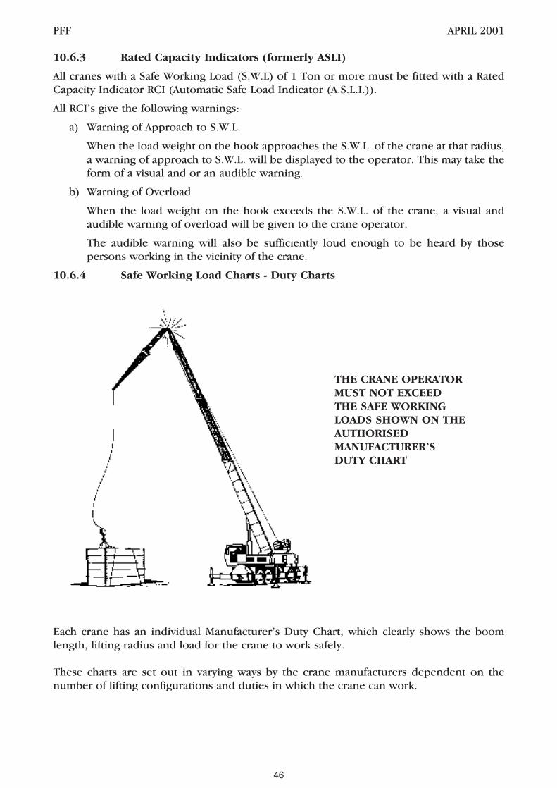
10.6.3 Rated Capacity Indicators (formerly ASLI)
All cranes with a Safe Working Load (S.W.L) of 1 Ton or more must be fitted with a RatedCapacity Indicator RCI (Automatic Safe Load Indicator (A.S.L.I.)).
All RCI’s give the following warnings:
a) Warning of Approach to S.W.L.
When the load weight on the hook approaches the S.W.L. of the crane at that radius,a warning of approach to S.W.L. will be displayed to the operator. This may take theform of a visual and or an audible warning.
b) Warning of Overload
When the load weight on the hook exceeds the S.W.L. of the crane, a visual andaudible warning of overload will be given to the crane operator.
The audible warning will also be sufficiently loud enough to be heard by thosepersons working in the vicinity of the crane.
10.6.4 Safe Working Load Charts - Duty Charts
Each crane has an individual Manufacturer’s Duty Chart, which clearly shows the boomlength, lifting radius and load for the crane to work safely.
These charts are set out in varying ways by the crane manufacturers dependent on thenumber of lifting configurations and duties in which the crane can work.
PFF APRIL 2001
THE CRANE OPERATORMUST NOT EXCEEDTHE SAFE WORKINGLOADS SHOWN ON THEAUTHORISEDMANUFACTURER’SDUTY CHART
46

10.6.5 Stability of Cranes
The stability of mobile cranes relies on the following factors.
a) That the ground is suitably compacted and levelled. Underground services orconstructions may suffer damage or collapse due to a crane passing over or nearby,which in turn may lead to the crane overturning.
b) That the outrigger beams on the crane are extended to the required lengths orpositions in accordance with the crane manufacturers specified duties anddimensions.
c) That the outrigger jacks are extended to raise the crane wheels free of weight e.g.,off the ground.
d) That adequate support material has been positioned under the outrigger jacks toprevent them sinking into the ground whilst lifting loads.
e) That the crane carries out lifting strictly in accordance with the manufacturers tablesof Safe Working Loads e.g., Duties charts.
f) The following outrigger jack loading table is for guidance only and shows themaximum theoretical loads for 4 and 10 tonne lifts and “worst case” scenario. Cranemodel specific outrigger loadings are available from the crane owner.
g) The Crane Supervisor and Crane Operator must monitor ground conditions duringthe course of erection, paying attention to deterioration as a result of usage andadverse weather.
NOTE: The crane can carry only a finite amount of timber or other support material, shouldthere be a requirement to erect the crane on a slope or ground that is not adequatelycompacted, there could be insufficient support material with the crane. This must beconsidered and designed in the planning stages of the job.
PFF APRIL 2001
1 2 3 4Crane Capacity Maximum Jack Maximum Jack Maximum Jack
load (kg) load (kg) load (kg)with 4t on with 10t on worst casethe hook 3 the hook scenario
10 tonnes 8,250 13,300 13,300 15 tonnes 13,110 15,930 16,200 20 tonnes 16,740 19,800 21,400 25 tonnes 18,410 22,740 27,500 30 tonnes 26,260 30,430 33,200 35 tonnes 28,000 29,000 33,000 40 tonnes 20,890 31,970 48,100 50 tonnes 34,000 35,000 47,000 55 tonnes 30,800 32,100 54,000 60 tonnes 36,000 45,000 55,000 70 tonnes 33,600 35,900 52,200 80 tonnes 33,500 35,000 61,700 90 tonnes Seek advice from‘and over’ the crane owner
47

10.6.6 Use of Outriggers
NOTE: In order to keep full ratings “on outriggers” all beams have to be fully extended andall wheels off the ground.Some cranes have duties for free on wheels and/or short outrigger base. For moreinformation refer to manufacturers’ duty charts.
PFF APRIL 2001
48

10.6.6 (CONTINUED)
PFF APRIL 2001
49
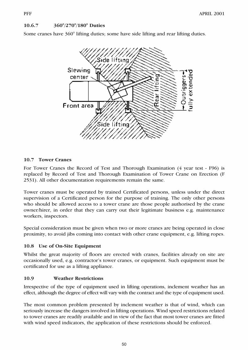
10.6.7 360°/270°/180° Duties
Some cranes have 360° lifting duties; some have side lifting and rear lifting duties.
10.7 Tower Cranes
For Tower Cranes the Record of Test and Thorough Examination (4 year test - F96) isreplaced by Record of Test and Thorough Examination of Tower Crane on Erection (F2531). All other documentation requirements remain the same.
Tower cranes must be operated by trained Certificated persons, unless under the directsupervision of a Certificated person for the purpose of training. The only other personswho should be allowed access to a tower crane are those people authorised by the craneowner/hirer, in order that they can carry out their legitimate business e.g. maintenanceworkers, inspectors.
Special consideration must be given when two or more cranes are being operated in closeproximity, to avoid jibs coming into contact with other crane equipment, e.g. lifting ropes.
10.8 Use of On-Site Equipment
Whilst the great majority of floors are erected with cranes, facilities already on site areoccasionally used, e.g. contractor’s tower cranes, or equipment. Such equipment must becertificated for use as a lifting appliance.
10.9 Weather Restrictions
Irrespective of the type of equipment used in lifting operations, inclement weather has aneffect, although the degree of effect will vary with the contract and the type of equipment used.
The most common problem presented by inclement weather is that of wind, which canseriously increase the dangers involved in lifting operations. Wind speed restrictions relatedto tower cranes are readily available and in view of the fact that most tower cranes are fittedwith wind speed indicators, the application of these restrictions should be enforced.
PFF APRIL 2001
50
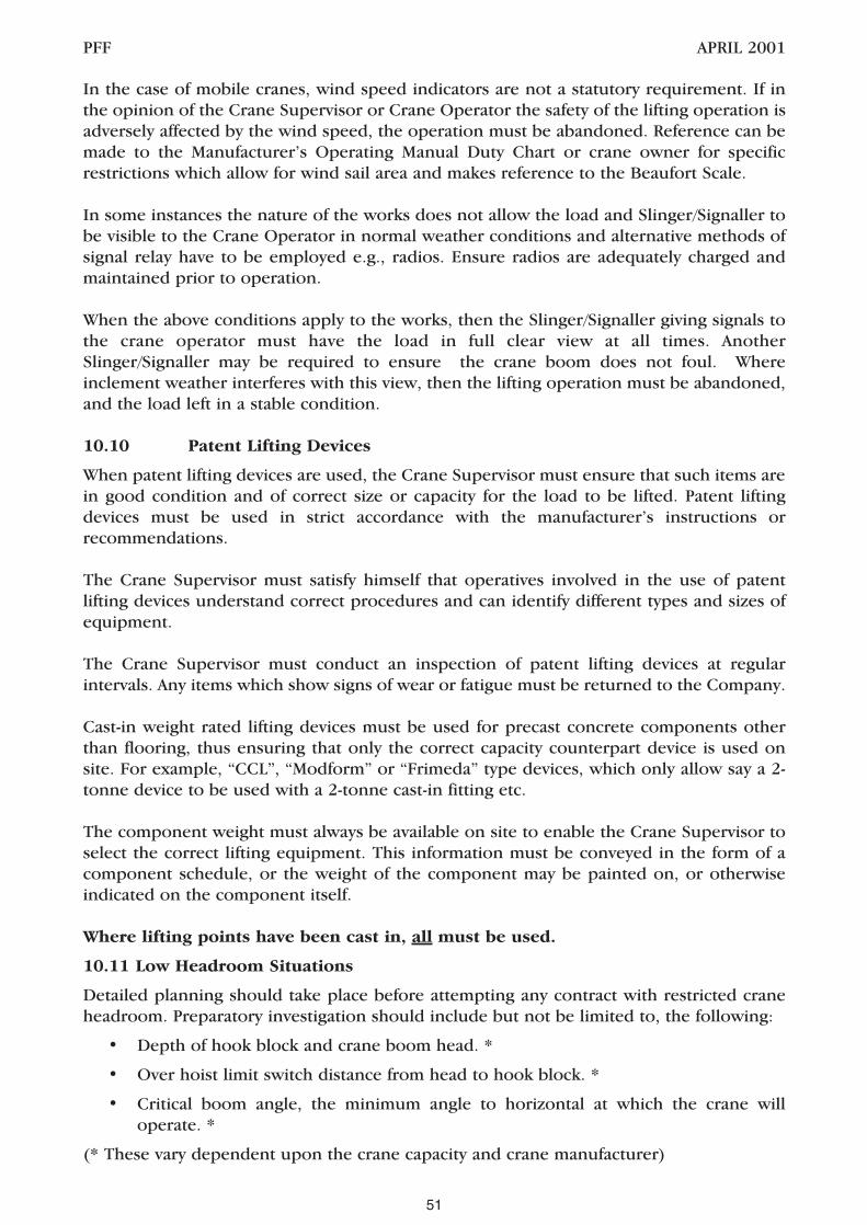
In the case of mobile cranes, wind speed indicators are not a statutory requirement. If inthe opinion of the Crane Supervisor or Crane Operator the safety of the lifting operation isadversely affected by the wind speed, the operation must be abandoned. Reference can bemade to the Manufacturer’s Operating Manual Duty Chart or crane owner for specificrestrictions which allow for wind sail area and makes reference to the Beaufort Scale.
In some instances the nature of the works does not allow the load and Slinger/Signaller tobe visible to the Crane Operator in normal weather conditions and alternative methods ofsignal relay have to be employed e.g., radios. Ensure radios are adequately charged andmaintained prior to operation.
When the above conditions apply to the works, then the Slinger/Signaller giving signals tothe crane operator must have the load in full clear view at all times. AnotherSlinger/Signaller may be required to ensure the crane boom does not foul. Whereinclement weather interferes with this view, then the lifting operation must be abandoned,and the load left in a stable condition.
10.10 Patent Lifting Devices
When patent lifting devices are used, the Crane Supervisor must ensure that such items arein good condition and of correct size or capacity for the load to be lifted. Patent liftingdevices must be used in strict accordance with the manufacturer’s instructions orrecommendations.
The Crane Supervisor must satisfy himself that operatives involved in the use of patentlifting devices understand correct procedures and can identify different types and sizes ofequipment.
The Crane Supervisor must conduct an inspection of patent lifting devices at regularintervals. Any items which show signs of wear or fatigue must be returned to the Company.
Cast-in weight rated lifting devices must be used for precast concrete components otherthan flooring, thus ensuring that only the correct capacity counterpart device is used onsite. For example, “CCL”, “Modform” or “Frimeda” type devices, which only allow say a 2-tonne device to be used with a 2-tonne cast-in fitting etc.
The component weight must always be available on site to enable the Crane Supervisor toselect the correct lifting equipment. This information must be conveyed in the form of acomponent schedule, or the weight of the component may be painted on, or otherwiseindicated on the component itself.
Where lifting points have been cast in, all must be used.
10.11 Low Headroom Situations
Detailed planning should take place before attempting any contract with restricted craneheadroom. Preparatory investigation should include but not be limited to, the following:
• Depth of hook block and crane boom head. *
• Over hoist limit switch distance from head to hook block. *
• Critical boom angle, the minimum angle to horizontal at which the crane willoperate. *
(* These vary dependent upon the crane capacity and crane manufacturer)
PFF APRIL 2001
51

The length of the units will dictate the length of chain brothers required – see diagram.Patent lifting devices can be used, which may affect the headroom. The effect of liftinginclined units should also be considered.
10.12 Lifting Inclined Pre-stressed Precast Flooring Units
Units can be lifted at an angle with the same capacity chains as described below, providedthe chain leg is always less than 45° to the vertical. Lifting inclined units is dependent upon:-
• Unit Integrity
• Grip by choke hitch
• Suitability of bearings to land angled units
e.g.
PFF APRIL 2001
Boom head
Over hoist limit switch
Hook block
Chain master link
‘H’ = Approx 0.25 x unit length
Note: Chain brothers must be rated @ 120ºor 45º – 60º to vertical.
52
‘H’60º
120º

10.13 Chain Slings
Under the LOLER Regulations 1998, slings are classified as an ‘accessory for lifting’ (R2)meaning work equipment for attaching loads to machinery for lifting. Effectively nothinghas changed and the more generic term of lifting tackle would still encompass chain slings,web slings, eyebolts, shackles etc.
All lifting tackle under the LOLER regulations should be: -
• Marked with its SWL (Safe Working Load) or WLL (Working Load Limit)
• Contain information that indicates its SWL for each configuration
• Thoroughly Examined every 6 months
• In certification either with a Declaration of Conformity, Thorough Exam Report orOriginal Test Certificate.
Chain slings used for general lifting purposes should now be manufactured to BS EN 818-4 (1996) for Grade 8 chain. This standard calls for all slings manufactured for general useto be rated in the UNIFORM method for ranges of angles from 0° to 45° to the vertical orfrom 45° up to and including 60º to the vertical as shown in the table below.
Each sling should also have relevant information on an affixed tag, which shows:
• number of chain legs
• nominal size of chain in mm
• lifting capacity at 45º to vertical, angle ß
• lifting capacity at 60º to vertical angle ß
The capacity of chains marked in the UNIFORM method cannot be increased by reducingthe included angle.
Chain slings rated in the TRIGONOMETRICAL method are no longer manufactured forgeneral-purpose use within BS EN818-4.
PFF APRIL 2001
Normal size Maximum Safe Working Load
of chain Two-leg slings
0º < ß ≤ 45º 45º < ß ≤ 60º
mm Tonne Tonne
8 2.8 2
10 4.25 3.15
13 7.5 5.3
16 11.2 8
ß
53

Although chain slings are manufactured to the new standard and rated in the UNIFORMmethod, existing slings previously rated in the TRIGONOMETRICAL method can still beused, provided they are regularly inspected have the relevant certification. The TRIGmethod provides for a variation in the WLL as the angle to the vertical varies and was acommon practice throughout the UK for multipurpose applications (LEEA). Care must begiven when using slings rated in the TRIG method as the Slinger must be provided withtables showing the SWL at various angles for each size of chain as there is an inherentdanger of overloading the sling if the angles have been misjudged.
Pre-cast concrete units are often lifted by the ‘choke hitch’ method of slinging. When thismethod is used the SWL can be reduced by up to 20% but always refer to the manufacturer’stable of SWL.
The full implications of the changes in standards (EN818-4) and legislation (LOLER &PUWER) will take time to work through to the owner and end users of the equipment.Current methods are now rated in the UNIFORM way rather than the TRIGONOMETRICALway. To avoid confusion new slings should also be stamped with the ‘CE’ mark and beissued with an EC Declaration of Conformity which replaces the more traditional TestCertificate. Slingers should be aware of these changes both with the revised rating methodand different methods of marking i.e. WLL (Working Load Limit) rather than SWL, 0º – 45º,chain angle to vertical, rather than 0º – 90º, included angle.
10.14 Multiple Leg Slings
Multiple Leg Slings are comprised of three or four legs, which are connected byintermediate links to the master link and are marked with the safe working load andidentification serial number on the master link or tag. The SWL will be calculated by usingeither the UNIFORM or the TRIGONOMETRICAL method.
When using multiple leg slings, it is important to assess the centre of gravity of a componentprior to lifting, to determine an effective slinging arrangement. If in doubt, the CraneSupervisor must refer back for technical advice on the choice of lifting slings, as multipleleg slings are rated on equal loading in each leg.
10.15 Lifting Forks, Grabs and Block Handling Devices
When beam and block floor components are to be installed, some form of lifting fork, grabor scissors may be used in handling the blocks. Block handling equipment, as describedabove, must not be used unless a suitable net is placed and secured around the load inorder that falling blocks or debris are restrained. Persons handling these lifting devicesmust be trained and competent in their use and restrictions.
The nets used must be of a suitable mesh and gauge to prevent the fall of material and mustbe inspected by the Foreman for damage at the commencement and completion of eachcontract, or more frequently on longer contracts. Any net found to be of such poorcondition that its functional ability is impaired, must not be used.
Before allowing blocks to be hoisted, the person slinging loads must ensure that the palletor cube of blocks is stable and properly packed. This is of particular importance wherescissor grabs or clamps are used.
As with other forms of lifting gear, patent block handling devices must be marked with theirSWL and identification and be tested and examined in the same way as other forms of liftinggear and should be marked with their self weight.
PFF APRIL 2001
54

10.16 Lift Trucks
Lift trucks are sometimes used to place components in conditions where reducedheadroom or access makes other forms of lifting impracticable.
When a lift truck is to be used, the Company Representative must ensure that adequateaccess and working areas are provided, in the same way as crane access and standing areasare agreed. Account should be taken of the terrain, height restrictions, noise, workingenvironment etc.
Should any attachment be used in conjunction with a lift truck, the selection andinstallation of the attachment must be carried out in consultation with the manufacturer orhirer of the lift truck and the rated SWL altered accordingly.
If it is necessary for the lift truck to travel with units, the route across site should be chosenwith care, avoiding adverse gradients, obstructions, and wherever necessary additionalhardcore or similar measures should be implemented to minimise the unevenness of thesite. Loads must be kept as low as possible to the ground to prevent the truck becomingunstable.
At all times the operation of lift trucks must be carried out in full conformity with theinstructions or recommendations of the hire company and/or the manufacturers, withparticular attention being paid to the SWL and weight/ height restrictions.
The Foreman must ensure that the person delegated to operate the lift truck is certificatedand is the only person allowed to operate the vehicle.
When handling precast components on the forks of a lift truck, it will be necessary to ensurethat the forks of the vehicle are spaced such that no damage is caused to the componentbeing handled and that stability is maintained at all times.
PFF APRIL 2001
55

PFF APRIL 2001
56

11 MOVEMENT OF UNITS BY OTHER MEANS
11.1 Barring
Components should be positioned as near as possible to their final position to minimisebarring, however, the use of pinch or crow bars to move components is common to alltypes of floor unit and all categories of contract. The bar is used to move individual unitsinto their final position, and to tighten up a floor after laying.
In whatever situation barring is carried out, there are basic precautions that must beobserved:
The ability of the structure to withstand this type of movement must be considered at thedesign stage and the erectors must satisfy themselves as to the robustness of the bearingsbefore carrying out this operation and seek professional advice if unsure. If barring cannotbe avoided and the bearings are not considered robust enough then the units must not bepositioned until the bearing is improved or some temporary measures taken such asproperly designed temporary support to the components or bracing of the bearings
The bar itself must be of sound construction and of adequate strength, and should be longenough to enable the person barring the component to stand upright.
The end of the bar should be shaped such that it can gain maximum purchase onto the unitto be moved, and the heel of the bar must be able to fully bear onto the units or structurebeing barred against.
Brickwork, blockwork or other masonry members should not be used to provide a surfaceto bar against, and where a possibility of damage to other surfaces exists, protectivemeasures should be employed to prevent spalling or fracture.
Components should not be moved by this method unless there are sufficient units or otherelements of structure to provide a suitable platform on which the person(s) carrying outthe operation can stand. Such a platform must be of sufficient size to enable the person toproperly brace himself and to ensure that in the event of bar slippage, the person will notfall through a void, or over an edge.
PFF APRIL 2001
57

When moving components by this means, care must be taken to ensure that the units arenot damaged to an extent which will impair their structural integrity.
Components must be positioned or moved by a succession of small movements. Noattempt should be made to slide or lift units for distances that would cause the person(s)involved in the operation to lose their balance, or to hold excessive weight on a bar.
11.2 Jacking
Whilst the use of jacks to move units is not common, they are in some instances suited tosuch work.
Whenever jacks are used, they must be of adequate strength and capacity to safely raise andhold the load. Steel or hardwood wedges should be used to provide an additional safeguardwhen a component is required to remain raised for some time and whenever practicable,adjustable steel props should be used. When jacking up a component, the Foreman mustensure that the jack is sited on a firm level base. If jacking from a floor, the Foreman mustensure by reference to the Company, that the floor is capable of safely supporting the jackand the weight of any load being raised.
Care must be taken to ensure that the operation does not make the bearings unstable byintroducing additional load or lateral forces to one end or leave the component in anunstable condition such that it could move whilst supported on the jack(s)
No person will be allowed access to the area above whilst jacking is taking place and onlyessential personnel will be allowed in the working area below.
Jacks are often used in conjunction with adjustable steel props to raise components to arequired level. In such circumstances, the Foreman must ensure that the adjustable prop isheld vertically and will adequately carry the load. Components must only be raised a fewmillimetres by this means; greater lifts or movement must be undertaken by liftingappliances.
Where jacks are employed to apply side thrust to components, purpose-made jacks shouldbe used and the Foreman must ensure that the component is capable of withstanding theload imposed by the jack, by reference to the Company if necessary.
In all cases, jacks must be used in compliance with the instructions and recommendationsof the manufacturer. The Foreman should conduct regular visual examinations of jackingequipment. Any defective items must not be used.
11.3 Bogies
In situations where units cannot be transported to their lifting position by crane, bogies areoften used.
The construction of bogies will vary from company to company, but their basic requirementwill be the same. They must be of sufficient strength to carry safely the weight of thecomponent and they must be so dimensioned as to allow sufficient bearing.
The units to be transported should be positioned centrally along the bogie with an evenoverhang both sides. During transportation care must be taken to avoid impact damage tothe beam and any excessive unevenness, which could cause the bogie to jump and breakthe component.
PFF APRIL 2001
58

Written confirmation must be sought of the suitability of the floor to carry the loads
The route across a floor should be carefully examined by the Foreman and additionalmeasures taken to safeguard the floor and the person(s) transporting the component andbogie. The route should run as close to the bearings as possible. Temporary propping tothe floor may be necessary and the Foreman should seek advice from the Company beforeallowing the operation to commence.
Where the floor to be protected is of a beam and block construction, the route should besuitably protected to prevent cracking or failure of infill blocks. The floor supplier’s adviceshould be sought.
During the fixing operation, bogies should be examined by the Foreman for damage ordeterioration and any defects should be remedied before further use, or the bogie scrappedif beyond repair. If manual handling is unavoidable then consideration must be given to theweight, physical dimensions, methods of carrying/ movement, distance to be carried, accessand number people necessary.
11.4 Chain Blocks, Tirfors etc.
This equipment should be anchored to a suitable safe point, which is capable ofcounteracting the weight of the component being pulled/ lifted, without risk of damage ormovement.
The Company Representative must ensure that any anchorage fits the above criteria, andshould seek professional advice as to the suitability of the anchor point.
It should be noted that the effective weight of a component to be moved will be greatlyincreased as a result of the friction between the component and the surface it is beingmoved on and technical advice should be sought. Consideration should be given tomethods of reducing the friction.
11.5 Winches Poles and Beams
Whilst these are rarely used in precast concrete erection, there may be occasions withinconfined areas when this is the only means by which components can be hoisted into place.
The company’s Representative must consider very carefully the choice of equipment andsiting. The total operation must include considerations for the temporary loadingconditions and be carefully planned and addressed within the Work Method Statement.
The elements of manual handling must also be considered and included within SafeWorking Method Statements and any Risk Assessment.
Before operating the equipment the Foreman must be fully trained in the use of andunderstand the Operators Manual with particular emphasis to the limitations and methodsof operations, maximum load and safety checks required.
PFF APRIL 2001
59

PFF APRIL 2001
60

12 ADDITIONAL ON SITE WORKS
12.1 Temporary Structural Support
The practice of erecting precast units onto temporary bearings must be avoided whereverpossible. In cases where such measures are unavoidable, the requirement to fix ontemporary bearings must be notified to the precast concrete company at the design stageof the contract and fixing must not progress until written confirmation has been obtainedby the Contractor’s Representative from a competent technical authority that the structurehas been suitably designed.
12.2 Propping
Where temporary propping is necessary to give additional support to the floor, e.g. until acomposite structural screed has matured, props must bear onto head trees and soleplatesto minimise point loads.
The Foreman must refer back to the Company Method Statement and relevant drawings forinstruction relative to the spacing and placing of props and the possible need to lace andbrace props when in position.
Propping must line through all floor levels, terminating at solid sound footing, particularcare being exercised to avoid buried pipes, channels or the like which have previously beenidentified by the Contractor’s Site Representative. Such propping must only be removed inaccordance with instructions from the Building Designer and the Principal Contractor’sMethod Statement.
12.3 Insitu Concrete
Wet concrete, mould oil and timber treatments are skin irritants and the requirements ofthe COSHH Assessment and the Personal Protective Equipment at Work Regulations mustbe applied.
Insitu concrete work must be executed in accordance with Working Drawings and SafeWorking Method Statement.
Insitu concrete can be supported either on permanent shutters, or on formwork. In thecase of permanent shutters, these should be tight fitting one to another and their sizeshould be such that the total area of concrete is supported. Permanent shutter units mustbe examined for cracking or other damage before any wet concrete is placed on them.These may need propping until the concrete is adequately cured. Where props are usedthese must be designed by a competent person with due regard to number and positionand installed as directed by the Designer.
No insitu works should be carried out without reference to the flooring supplier so that anydesign implications can be assessed and the work recorded.
When formwork is used, this must be of sufficient strength to support its own weight, andthat of the concrete, together with reinforcement and the weight of any operatives or plantengaged in the work. Formwork and steel reinforcement must be designed, constructedand erected by competent persons and should be closely examined before, during and afterthe placing of concrete, in accordance with the requirements of current recommendationsand legislation (see BS5975 - Code of Practice for Falsework).
PFF APRIL 2001
61

The contractor must ensure that adequate scaffold for safe access to the work place is madeavailable.
When using a mobile poker, care must be taken that the power unit is stood on a firm, levelbase and operated in accordance with the manufacturers instructions.
Before commencing any insitu concrete placement, the Foreman should ensure that theweather conditions are satisfactory so far as could be reasonably foreseen. Concretingshould not commence in conditions likely to cause its failure or displacement, unlessadequate measures are implemented to protect the concrete. In all cases where work is notcommenced, or doubt exists as to the suitability of weather conditions, the Company’sRepresentative must advise the Company of the situation.
GUIDANCE FOR INSITU WORK IN COLD WEATHER
Whilst insitu work is in progress, the Foreman should ensure that the area beneath thework being executed is kept clear of all personnel not engaged in this work
12.3.1 Concrete Screeds/Toppings
Concrete can be delivered to the point of placement by various methods, e.g.,
a) concrete pump
b) crane and skips
– special precautions are required for each operation.
It should be noted that any operative working a concrete pump must hold a certificate ofcompetence.
The use of cranes is covered in Section 10 and concrete skips used must be only thosespecifically designed for the purpose and fully supported with current test certificates.Particular care must be taken when passing the concrete skip through other elements of thestructure to ensure that it does not accidentally strike them or become entangled.
PFF APRIL 2001
62

Excessive heaping of the concrete must be avoided also and should be taken to preventimpact loading from the concrete, for example discharging a skip or pump from a height ofmore than 0.5m.
12.3.2 Grouting
The procedures for grouting are similar to those for insitu concrete and screeding. TheWork Method Statement and drawings must be referred to for the mix specification, jointdetails and responsibility for carrying out the work. The material can be delivered to site ina ready mixed form or alternatively mixed on site from dry materials.
Loading out of floor must be avoided until the grout has cured for not less than 72 hours.
Formwork must only be removed after the concrete has achieved sufficient strength, andthe curing time allowed should be as stated by the Designer.
12.4 Forming of Holes
Holes will normally be formed in components during manufacture. However additionalholes may be formed after reference to the precast flooring supplier.
PFF APRIL 2001
63

PFF APRIL 2001
64

13 ACCESS TO WORKING AREA, WORK AT HEIGHT & PROTECTION AGAINSTFALLS
13.1 General Principles for Preventing Falls
Regulation 6(1) of The Construction (Health, Safety and Welfare) Regulations 1996 (CHSW)requires that suitable and sufficient steps be taken to prevent, so far as is reasonablypracticable, persons falling. Where the potential fall is two metres or more, Regulation 6(3)lays down a hierarchy of control measures to be taken. Top of the hierarchy is the use ofplatforms, with guardrails and toe-boards, whilst fall arrest systems are at the bottom of thehierarchy.
Under the above Regulations, all parties including Principal Contractors, Contractors andSub-contractors have legal duties to provide suitable and sufficient measures to preventfalls from height.
There is a range of measures available. Passive systems, such as working platforms, staging,safety nets, air bags are the preferred method of protection. Active systems, such as workrestraint/fall arrest, using safety harnesses, lanyards and anchor points should only be usedwhen passive systems are not reasonably practicable. All of these should be consideredwithin a hierarchy of measures and selection will be dependent upon the type of floor beinginstalled and the structure the floor is being installed into. The hierarchy should befollowed and the system that affords the most reasonably practicable level of protectionshould be employed.
This area is under constant review and investigation by the members of the Precast FlooringFederation, from whom the latest information can be obtained.
13.2 Safe Access to the Working Area
Safe means of access to the working area requires careful planning particularly where workprogresses during installation. Typical methods are:
• Ladders;
• Independent scaffolds;
• Fixed or mobile scaffold towers;
• Mobile access equipment;
More detailed advice on the selection and use of access equipment is given in HSEguidance.
13.2.1Ladders
Temporary access onto and about the flooring will usually take the form of ladders, to ascaffold or platform provided as an Attendance by the Contractor. Ladders cannot be usedas a safe working platform whilst installing floor systems and should only be used as accessor for short duration work e.g. fixing anchor points.
PFF APRIL 2001
65

Properly constructed and secured ladders combined with the use of safety harnesses, staticlines or anchorage points may also be practicable in certain conditions where the workingheight precludes the use of mobile towers.
When ladders are used, they need to be of the right type, i.e. a suitable grade of industrialladder. They should be in good condition and effectively secured to prevent movement.Permanent means of securing ladders at identified access points can improve ladder safety.This avoids the need for footing when ladders are tied and untied. Those who use, inspectand secure ladders should be competent to do so.
Ladders may provide safe access, but their use is not always appropriate. Factors to beconsidered include:
• the length of the ladder required. Very long ladders are heavy to handle and mayneed staying to reduce flexing in use;
• the need to carry tools, equipment, materials, small components, etc.. Both handsshould be free when climbing a ladder.
The Foreman must visually inspect all ladders provided for use during the installationprocess, and any defects noted must be brought to the attention of the Company, or whereappropriate the Contractor’s Site Representative, so that the particular item can be replacedor repaired before it is used.
PFF APRIL 2001
66
Diagram 13a Diagram 13b
LADDERSAFETY –EVERYFOUR UPGO 1 OUT.
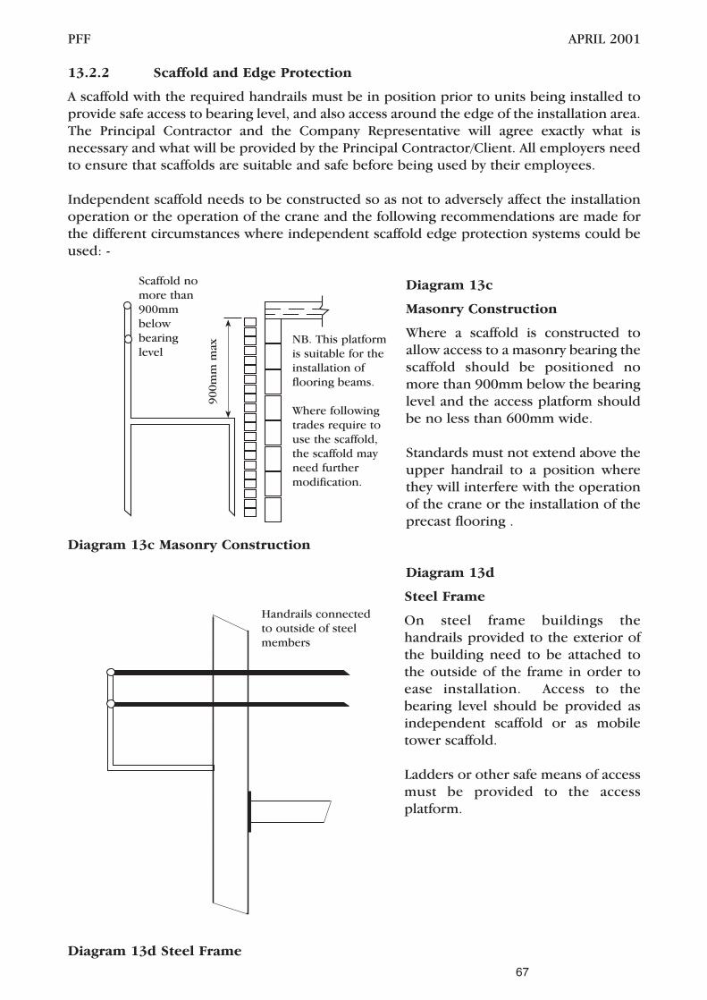
13.2.2 Scaffold and Edge Protection
A scaffold with the required handrails must be in position prior to units being installed toprovide safe access to bearing level, and also access around the edge of the installation area.The Principal Contractor and the Company Representative will agree exactly what isnecessary and what will be provided by the Principal Contractor/Client. All employers needto ensure that scaffolds are suitable and safe before being used by their employees.
Independent scaffold needs to be constructed so as not to adversely affect the installationoperation or the operation of the crane and the following recommendations are made forthe different circumstances where independent scaffold edge protection systems could beused: -
Diagram 13c
Masonry Construction
Where a scaffold is constructed toallow access to a masonry bearing thescaffold should be positioned nomore than 900mm below the bearinglevel and the access platform shouldbe no less than 600mm wide.
Standards must not extend above theupper handrail to a position wherethey will interfere with the operationof the crane or the installation of theprecast flooring .
Diagram 13d
Steel Frame
On steel frame buildings thehandrails provided to the exterior ofthe building need to be attached tothe outside of the frame in order toease installation. Access to thebearing level should be provided asindependent scaffold or as mobiletower scaffold.
Ladders or other safe means of accessmust be provided to the accessplatform.
PFF APRIL 2001
67
Scaffold nomore than900mmbelowbearinglevel
900m
m m
ax
NB. This platformis suitable for theinstallation offlooring beams.
Where followingtrades require touse the scaffold,the scaffold mayneed furthermodification.
Handrails connectedto outside of steelmembers
Diagram 13c Masonry Construction
Diagram 13d Steel Frame

Diagram 13e
Internal Fixing
When precast flooring componentsare being installed inside an existingbuilding, the headroom that thecrane can work in is severelyrestricted. See sections 8 and 10 forlow headroom situations.
The scaffold access must be designedso as to ensure that the crane willnot be adversely affected by thescaffold system.
This means that the standards mustnot extend above the bearing level ofthe beams and that the top handrailmust be level with the bearingsupport.
The provision of these types of access needs to be considered in the calculations for thecrane specification due to the increase in stand-off distance from the building.
A system of passive fall protection must be provided to the internal area of the building andany handrails must not extend above the bearing level.
13.3 General Systems of Protection
13.3.1 Beam and Block Flooring
Hazards
The main hazards associated with the installation of Beam and Block flooring at upperlevels are work at height and injury due to falling between the beams or from thesupporting structure.
Control
By definition an upper floor will normally be constructed at least 2 metres above the floorbelow. Precautions, in a practical manner, are to be taken to prevent operatives who areinstalling floors from falling, bearing in mind the following:
It will be necessary for the operatives to stand above the bearing surface to adjust theposition of the beams from their initial position to that specified in the layout drawings. Ifthe T-beams share a common staggered bearing it will be necessary to lift one set of T-beams over beams in the adjacent bay.
During construction of the Beam and Block floors it is necessary for the operatives to walkon the units to place the infill blocks from above.
Where beam and block flooring is being installed it is a requirement of this Code that thearea below the floor being installed is fully protected by a passive system of fall protection.
PFF APRIL 2001
68
The tophandrail mustnot extendabove thebearing level
Diagram 13e Internal Fixing

Diagram 13f
Beam and Block
This diagram shows theperimeter scaffold aroundthe perimeter of thebuilding, and the passiveprotection positioned tothe internal areas.
Where the installation istaking place in a steelframe building thescaffold requirement maychange to perimeterhandrails, however thepassive protectionrequirement is the same.
13.3.2 Stairs
Hazards
The main hazards associated with the installation of stairs are work at height and injury dueto falling from the incomplete staircase or into an exposed stair well.
Control
Stairs will require to be installed in such a way that access is required to each half landinglevel where the half landing is over 1.5m above the ground floor.
The diagrams below show typical examples of stair installation in steel and masonrystructures.
Diagram 13g
Stairs in Steel Frame
On steel framed structuresthe access platforms willneed to be at the bearingpositions. This will allowerectors to carry out theerection process from theplatforms and will onlyrequire them to move ontothe erected stair to removechains. During this timethe erectors will make useof fall arrest/work restraintequipment attached to theinstalled floor or thebuilding.
PFF APRIL 2001
69
Platform
Platform
Platform
Passive fall arrestsystem
Walls
Scaffold
Diagram 13f Beam and Block
Diagram 13g Stairs in Steel Frame

Diagram 13h Stairs In MasonryStructure
The first half landing can normallybe installed from the ground floor,however half landings at upperlevels will normally requireworking platforms. The erectorinstalling at first floor can beprotected by the use of workrestraint equipment so that theerector is prevented from workingbeyond the leading edge.
The formed stairwell must beprotected as soon as installation iscomplete. Stairs must not beconsidered as safe means of accessuntil they are provided withhandrails and their edges areprotected.
13.3.3 Hollowcore flooring
Hazards
The main hazard associated with the installation of Hollowcore Flooring at upper levels iswork at height.
Control
When hollowcore units are being installed, fall prevention and passive fall arrest systemssuch as safety nets, air bags and decking systems must be considered as the first option.Where such passive systems are not reasonably practicable then other active systems ofprotection (e.g. work restraint and harnesses, lanyards and anchor points) should be used.The suitability of these systems, their method of use and the limitations of use should beassessed on an individual project basis.
Diagram 13i –Hollowcore (typicaldetail) MasonryStructure
Protection to openingsand edges must beprovided. The PrincipalContractor/ Contractor isresponsible for theprovision of protection tovoids as they are formedand for the protection ofexposed edges.
PFF APRIL 2001
70
Anchor pointfor stair/landingsinstallation
Passive fallarrest system
Walls
Scaffold
1 2 3
4 5
6
Diagram 13h Stairs In Masonry Structure
Diagram 13i

PFF APRIL 2001
The independent scaffold must protect the perimeter of the building. The protection to theleading edge is provided by the use of passive fall arrest systems, such as air bags ordecking, which must be in place as shown on the diagram so that erection can start in bay1. Erectors start by working from the independent scaffold. Bay 6 is constructed similarlybut it contains the staircase opening.
Where alternative fall arrest/protection methods such as work restraint or active fall arrestsystems are used they must be validated and specified taking into account the potentialdrop height. Where such systems are employed they must offer the same or better level ofprotection than the passive system.
Diagram 13j Hollowcore (typi-cal detail) Steel Frame
The area below the floor beingerected should be protectedwherever possible by the use ofpassive fall protection systemssuch as nets or air bags.
Where the use of such systems canbe shown to be impracticableother systems such as workrestraint or fall arrest must beused. These systems must bevalidated, specified andsupervised, taking account of thepotential drop height.
13.4 Hierarchy for Fall Protection, Prevention and Arrest
The hierarchy to be used has been outlined in section 13.1 above. In practice the followingsystems are available and are categorised as follows.
Passive Systems – Systems that do not rely on the installer to operatethem and are in place prior to the first unit beinginstalled. Passive systems include nets, air bags,decking and many other systems. Passiveprotection is the top of the hierarchy of protectivemeasures to be taken. Passive systems must bevalidated and tested and appropriate for use in theapplication. Suppliers of this type of equipmentmust complete the assessment process detailed insection 15 of this Code before their products areput to use.
Active Work Restraint Systems - These systems rely on erectors to operate themand so are second in the hierarchy. Work RestraintSystems limit the access to the leading edge, sorestraining the individual and preventing the fall.These systems must be validated and the suppliersassessed as described under section 15 of thisCode.
71
Steel FrameProtectionSystem
ExternalHandrail
Formededge
Access platformor scaffold
Diagram 13j Hollowcore (typical detail)Steel Frame

Active Fall Arrest Systems – Systems for active fall arrest rely on the erector touse them and are the last item on the hierarchy ofcontrol measures. Systems involving the use ofthese systems require the calculation of themaximum drop an erector could suffer as a worstcase to ensure that the floor to floor height issufficient to prevent the fallen person coming intocontact with the floor. Rescue of the fallen personalso needs taking into account when designingsuch a system. These systems must be validatedand the suppliers assessed as described undersection 15 of this Code.
13.5 Safety Nets
Safety nets can be effectively employed to reduce potential falls and to minimise theireffects. They offer collective passive safety as they protect everyone working within theirboundary, without requiring those workers to act to be protected. They allow a broadrange of activity to continue with minimum restriction.
Safety nets have high energy absorption capability, and therefore offer a 'soft landing' thatminimises injury. THEY SHOULD ALWAYS BE FITTED AS CLOSE AS POSSIBLE TO THEUNDERSIDE OF THE WORKING LEVEL.
Safety nets overlaid with an appropriate plastic sheet, or a sufficiently fine mesh debriscover can prevent chains from snagging. Consideration should be given to the type ofmaterials likely to fall, e.g. fixings or tools, when selecting the overlay material. Safety netshave the additional advantage that materials are contained by the net and do not bounce.
13.5.1Erection Of Safety Nets
Those who erect nets should be aware of the relevant standards, trained and be competentto carry out the work safely. This may require the use of specialist installers and riggers,especially where large nets are being used.
13.6 Air Bags
Air bag systems comprise bags of varying sizes, which can be joined together at the tops toeffectively form a continuous surface. The air bags can be connected by a system of hosesand connectors, which in turn are connected to an air pump. The air pump is used toinflate the bags to the required pressure.
Prior to employing the empty air bags the whole of the area must be cleared of builders’debris, trestles etc. The air bags are then arranged to cover the desired area, connectedtogether and inflated.
Care must be taken to ensure that any openings are such as windows are covered to preventfalling objects from bouncing or rolling out of the building.
Care must also be taken to ensure that the air bags do not cause the surrounding structureto be displaced by the air pressure.
The airbags should be deflated and removed once the floor units have been installed toprevent them from becoming soiled during the grouting process.
PFF APRIL 2001
72

13.7 Working Platforms
Working platforms where provided should fully cover the internal area under thefloor installation.
Several options are available for achieving the working platform, including lightweightdecking systems and scaffolding. When scaffold systems are used care should be taken toensure that scaffold poles do not extend above the level of the deck, where they couldcause injury to a falling person or cause a trip hazard.
Details of currently available systems can be obtained form the Precast Flooring Federationat the address in this document.
13.8 Safety Decking System
Safety decking is a lightweight plastic platform system, which may form either a simplecrash deck or a working platform dependent on the method of assembly. This lightweightplatform system can be assembled to suit most internal areas. Safety decking provides asafeguard when working at heights whilst allowing full freedom of movement over theworking area. It consists of plastic panels, normally 1.2m x 1m supported on 2m lengthsof 50 mm diameter ABS plastic. These are connected by means of an ABS coupling device,which has been adapted to form a horizontal location between the panels and theirsupports. The supports are placed directly onto the existing lower floor with no positivelocation or bedding being required. The panels are then tied together using flexible ties.The floor area on which the safety decking bears must be firm and reasonably level. On siteinstallation of the safety decking is usually carried out the day before installation of theflooring and removed on completion of works.
13.9 Staging
When stagings e.g. ‘Youngman’ type boards are provided to form temporary access orworking areas, these must be secured, to prevent excessive movement or dislodgement.Should it become necessary to move staging during the course of the installation process,the Company Representative should designate a competent person(s) to carry out thiswork, and should be satisfied with the stability of the staging(s) before recommencingwork.
13.10 Access Platforms, Mobile Towers and Other Mobile Equipment
A wide range of equipment is available. For work of short duration, such as inspection andminor maintenance, it can provide excellent safe access. Risks associated with scaffolderection can often be avoided if mobile access equipment is used rather than scaffolding.However, the equipment chosen should be appropriate for the ground conditions on thesite. The manufacturer's advice on the maximum wind speed at which it can be safelyoperated should be followed.
Equipment should be maintained in a safe condition and be operated only by competentpersonnel.
Mobile towers must only be used on a firm level base and be constructed by competenterectors in strict accordance with the manufacturer’s recommendations and HSE Guidance,attention being paid to handrails, bracings, out-riggers and tying to the structure. Mobiletowers must be fitted with lockable wheels and should only be moved when unoccupied.Only those trained in tower scaffold installation should be given the task of erecting thismethod of access.
PFF APRIL 2001
73

When power operated mobile work platforms are used on site these machines must onlybe operated by a certificated operator. The ground must be firm and level and suitable forthis type of work. Particular attention must be paid to wind speed when working at height,as this will affect stability. The maximum height/wind speed data are available from theplant supplier.
The Foreman must visually inspect all such equipment provided for use during theinstallation process, and any defects noted must be brought to the attention of theCompany, or where appropriate the Contractor’s Site Representative, so that the particularitem can be replaced, or repaired, before it is used.
13.11 Active Fall Arrest Equipment – General
Work restraint can prevent a fall by restricting the movement of a person to a safe area. Itshould not be possible to reach any unprotected edge, hole or fragile material when relyingon this system.
Fall arrest is not the same as work restraint. Fall arrest aims to minimise injury once a fallhas occurred. Specialist advice should be sought from the supplier of the equipment on theprovision and location of suitable anchorage points. Supervision and training are neededto ensure that the system of work adopted is understood by all users and is maintained.
The main reason for the use of safety harnesses is to limit the distance of any fall andthereby minimise the risk of injury.
Active fall arrest systems provide valuable protection, but they are not a substitute foreffective fall prevention measures. It must be clearly understood that, where practicable,proper working platforms with guardrails and toe-boards, must be provided. Where theprovision of working platforms or the use of passive fall arrest systems is impracticable,active fall arrest systems must be provided and used.
It is imperative that a suitable secure method of fastening the lanyard to a fixed point isconsidered such that the lanyard length will prevent a fall.
In choosing a harness, care must be taken to ensure that it will give the user, as far as iscompatible with safety, maximum comfort, freedom of movement and, in the event of a fall,every possible protection to the body from the shock of sudden arrest. Proper fittings andadjustment are essential to achieve these aims. The use of lanyards fitted with shockabsorbers is recommended.
Where the erector is at risk of injury from falls, suitable and sufficient precautions must betaken to minimize the risk of injury. Practical measures to achieve this include running linesand lanyards attached to suitable anchorage points which may be incorporated into theslab. Inertia reels may be used, however assessments must be based on their designlimitations and manufacturers’ recommendations.
Where fall arrest devices are being considered, adequate training must be provided tooperatives and the equipment must be inspected by competent persons before and after use.
PFF APRIL 2001
74

PFF APRIL 2001
13.11.1 Use of Active Fall Arrest Equipment – Training Requirements
All persons who will use fall arrest equipment must be fully trained in the appreciation,inspection and use of that equipment. The training must be provided by a suitably qualifiedinstructor and the course content should include as a minimum: -
• Selection of active fall arrest equipment.
• Inspection of active fall arrest equipment.
• How to inspect the equipment and recognise significant defects.
• Use and fitting of active fall arrest equipment and how equipment works together.
• How to wear the harness and adjust it to the body.
• How to manage the lanyard and other equipment.
• How to assemble the system correctly, including recognition of the importance ofsafe anchorages.
• Selection and use of anchorage points.
• Storage and record keeping requirements for active fall arrest equipment.
• Rescue and/or Self Rescue procedure.
• How to self rescue or assist others after a fall.
Active fall arrest systems are not foolproof and their safe usage is not always common sense.Without proper training in fitting, use, maintenance, installation and equipmentlimitations, all that a fall arrest system can provide is a false sense of security.
Where special equipment is provided those using it will require additional training in itsuse and how it operates in conjunction with the standard harness. Additional specialinstructions will be needed to ensure that personnel are aware of the equipment’s normaloperating conditions and what to do if something goes wrong.
13.11.2 Use of safety harnesses and running line systems
There is still a possibility of injury in an arrested fall. The system relies on the useraccepting the discipline to ensure that the equipment is consistently and effectively used.There will be circumstances, however, when it is not reasonably practicable to providepassive measures to prevent a person falling. In such cases, a full body harness attached toa suitably anchored system incorporating some form of energy absorber may be the onlyprecaution available. This at least ensures that if a fall occurs, it is safely arrested.
Fall arrest systems come in a variety of forms. These range from a single lanyard or aretractable type fall arrester attached to a fixed anchorage point through to proprietarymulti-span cable-based systems. All should be used with full body harnesses. The systemshould incorporate some form of energy absorber or energy dissipating element to ensurethat the deceleration forces on the user do not exceed 6 g. Fall arrest systems serve aspersonal protective equipment (PPE) against falls from height.
The provision and use of active fall arrest equipment is subject to the Personal ProtectiveEquipment at Work Regulations 1992.
The safe performance of an active fall arrest system depends completely on a suitableanchorage being provided. This could be a single fixed anchorage point or a flexible
75

anchorage line. The adequacy of all anchorages, including the ability of the supportingstructure to carry the anchorage loads, should be verified by calculation or by testing. Forexample, the structural adequacy of a guardrail to resist fall arrest forces should be assessedbefore a lanyard is anchored to it. Anchorages should generally be installed as high aspossible, preferably above the user and never below foot level.
In order for a fall arrest system to function correctly there must be adequate clearancebelow. When assessing the suitability of fall arrest equipment for a given situation theCompany must take into account the potential maximum fall height and specify equipmentthat adequately protects against it.
The maximum fall height could for example be made up of the original length of thelanyard plus shock absorber; the maximum allowable extension of the shock absorber; andthe displacement of the full body harness and the clearance below the feet of the user afterthe arrest.
When a flexible anchorage line system is used, allowance must also be made for the sag ofthe line between anchorages.
Consideration should also be given to how a person would be rescued after an arrested fall,particularly from high structures.
IN ANY CASE REFERENCE MUST BE MADE TO THE MANUFACTURER OF THE FALLARREST EQUIPMENT.
13.11.3 Inspection and Routine Maintenance of Fall Arrest Equipment
The user’s life may depend upon the good working order of the fall arrest equipmentprovided and therefore the equipment must be subject to routine inspection, maintenanceand, where required, replacement.
13.12 Other Fall Protection Systems
The Health and Safety Committee and Member Companies of the Precast FlooringFederation are continually researching the latest developments and systems for fallprotection and prevention. Further details are available from the Precast FlooringFederation.
PFF APRIL 2001
76

14 PROTECTION OF THIRD PARTIES
14.1 Other Trades or Persons on Site
The Work Area associated with the flooring erection must be designated a prohibited areato all persons, other than those engaged in the erection of the floor. The Contractor mustactively enforce this prohibition, and the Foreman must co-operate with the Contractor toensure that fencing, gates and barriers remain secure and that notices are not removed orobscured.
The Contractor and Foreman must ensure that components are not hoisted over areaswhere other persons are working. This may include several levels in multi-storey work.
Operatives engaged in the erection of the flooring must at all times execute their work witha due regard for the health and safety of other workers or persons. They must observe andcomply with the Safe Working Method Statement in force on any particular contract insofaras such rules or requirements affect their operations and they must also comply with anyrules or requirements imposed by the Contractor.
The Foreman must ensure that the components are fixed in accordance with the WorkingDrawings.
The Foreman must ensure that the Work Area is kept clean and tidy so far as this isreasonably practicable and at the end of the working day the area should be left free ofdebris. Materials must be safely stacked.
14.2 Members of the Public
The lifting of components and materials may present a hazard to the public, especiallywhere the delivery vehicle is unloaded from the public highway.
The work needs to be planned and executed to take account of the needs of children,people with prams, the elderly and those with disabilities.
When unloading from the public highway, the Contractor must obtain the necessarystatutory permissions and the area used for off loading must be designated a prohibitedarea to all persons other than those engaged in the installation of the floor.
The Contractor must provide all necessary cones, warning barriers, notices, traffic signs andlighting to allow the safe passage of pedestrians and roads traffic. If deemed necessary, itmay be required that the prohibited area is policed.
On sites where the building operations are in close proximity to public places or highways,additional care must be taken to prevent materials or debris falling from the works. Wherethe Contractor has provided measures to prevent such falls, or to protect the public, theoperatives engaged in the installation of the flooring must not remove or interfere withthese measures in any way.
When the installation involves the operation of a crane in a third party’s air space, thecontractor must obtain the necessary permissions and ensure that the appropriate steps aretaken to protect third parties and the public in these areas.
PFF APRIL 2001
77

Any debris or material which falls from delivery vehicles must be removed from the publichighway or public area and the area left clean and hazard free.
During the course of the lifting operation the Slinger/Signaller must ensure that membersof the public are not in the vicinity of the suspended load or lifting equipment.
The Foreman must liaise and co-operate in all respects with the Contractor’s SiteRepresentative to ensure compliance with any measures, provisions or rules previouslyagreed with the Contractor or with any statutory provisions for the protection of the public.
PFF APRIL 2001
78

15.1 Introduction
This procedure details the system for the selection and approval of suppliers of safetyequipment for protection against falls and sub-contractors used for the installation of fallprotection systems and those for the installation of precast concrete flooring.
This procedure defines the management system in place to ensure that suppliers and sub-contractors who may be employed by precast concrete companies have satisfied theselection criteria before their product or service is used.
15.2 Supplier and Sub-Contractor Assessment Application
Suppliers and sub-contractors may apply to be considered for inclusion on the list byapplying in writing to: -
Supplier/sub-contractor AssessmentPrecast Flooring Federation60 Charles StreetLeicesterLE1 1FB
The applicant will then be sent the selection criteria and Supplier/sub-contractorAssessment Form. The applicant must enclose all of the required information to allow theassessment to proceed. Once complete the application should then be sent to the aboveaddress.
Files are held by the Precast Flooring Federation of those suppliers and sub-contractorswho have satisfied the selection criteria and these files form the basis of the Approved Listto which member companies will refer.
15.3 Selection Criteria for Installation Sub-Contractors (precast concrete installers)
A prospective installer of precast concrete flooring and stairs must provide the following: -
1. evidence of adequate insurance cover.
2. details regarding the sub-contractor’s safety arrangements e.g. Safety Policy, RiskAssessments and method statements.
3. evidence to show that the personnel involved have been adequately trained in thesafe erection of precast concrete floor and stair elements as detailed within this Codeand have suitable and sufficient training in health and safety. (Section 3 of this Codedetails the training requirements for Trainees, Erectors, Foremen and Supervisorsand this will be used for assessment purposes).
4. evidence of previous experience in the type of work being applied for.
Approval of the application will be by the Precast Flooring Federation Health and SafetyCommittee.
PFF APRIL 2001
79

15.4 Selection Criteria for Suppliers/Subcontractors of Fall Protection Equipment
The supplier must provide: -
1. evidence that the product being supplied meets the current requirements (i.e. proofof independent testing to BS or EN standards etc.),
2. written confirmation that the product to be supplied is appropriate for use duringthe installation of precast concrete flooring and stair elements,
In addition to above the fall protection sub-contractor must provide: -
1. evidence of appropriate insurance cover where sub-contract installation is beingundertaken,
2. details regarding the sub-contractor’s safety arrangements e.g. Safety Policy, RiskAssessments and method statements.
3. evidence showing that personnel who will install any product are suitably andsufficiently trained to do so.
Approval of the application will be by the Precast Flooring Federation Health and SafetyCommittee.
15.5 Approved Suppliers/Subcontractors List
The list of approved suppliers, sub-contractors and installation sub-contractors is held andmaintained by the Precast Flooring Federation. Copies of the list are issued to all membercompanies. The List includes the name of the company and their scope of approval.
These being: -
A) Approved Supplier (Fall Protection Equipment)
B) Approved Sub-contractor (Fall Protection Equipment)
C) Approved Installation Sub-contractor (Precast Concrete Flooring and Stair elements)
The list of approved suppliers and sub-contractors is updated and circulated regularly bythe PFF Health and Safety Committee following review at the committee meetings. Allrecords relating to the approval/rejection of suppliers and sub-contractors are maintainedin the files of the Precast Flooring Federation.
Suppliers and sub-contractors may be suspended from the Approved Supplier List at thedecision of the PFF Health and Safety Committee and finally removed from the ApprovedSuppliers List by the Committee, as a result of poor service or inadequateperformance/product.
15.6 Records
The records relating to this procedure kept by the Precast Flooring Federation are: -
i) The Approved Suppliers List.
PFF APRIL 2001
80

ii) Supplier and Sub-contractor files, reports of performance and any complaintsagainst the supplier or product supplied.
iii) Copies of Test certificates or evidence of independent testing issued to support thesupply of materials or installation to specific standards.
iV) The completed questionnaire, filed with the supplier/sub-contractor files.
15.7 Supplier/Sub-contractor Questionnaire
See Appendix A, page 83
PFF APRIL 2001
81

PFF APRIL 2001
82

Appendix A
SUPPLIER/SUB-CONTRACTOR ASSESSMENT FORM
PFF APRIL 2001
83
emaN
sserddA
rebmuNenohpeleT rebmuNxaF
)s(emaNtcatnoC
?tuoyrracotesoporp/tuoyrracynapmoCruoyseodkrowtahW.1
epytsihttuodeirracynapmoCruoysaH.2?erofebkrowfo ON/SEY
snoitaicossAlacinhceTroedarTynafopihsrebmeM.3
seitivitcAynapmoCruoY.4
nacuoytahtsecivrestsilaicepsynagnidulcni,seitivitcaynapmoCniamruoytsilesaelP).cte,tnempiuqessecca,yevrus.g.e(edivorp

PFF APRIL 2001
84
Appendix A
SUPPLIER/SUB-CONTRACTOR ASSESSMENT FORM
ytefaSdnahtlaeH.5
?yciloPytefaSaevahuoyoD )ypocaesolcneesaelpseyfI( ON/SEY
esolcnEesaelProselpmaxEehtfoseipoc
gniwollof.noitatnemucod
foypoC )PF(sreilppuS )PF(nocbuS )tsnICP(noc-buS
yciloPytefaSdnahtlaeH
sdroceRgniniarT
stnemetatSdohteM
sliateDecnarusnI
stnemssessAksiR
stluseRtseTtnednepednI
retteLnoitamrifnoC
stnemucoDdesolcnEfotsiL
?evahuoyodseeyolpmeynamwoH.
oN
?stnedicnidnatnediccadrocerdnatroperuoyoD)sraeyowttsalehtfosliatedesolcneesaelP( ON/SEY
?ecivdaytefasdnahtlaehotsseccaevahuoyoDON/SEY
?snoitacifilauqriehteratahwdnaecivdasihtsedivorpohW
ksirdnastnemetatsdohtemedivorpotelbauoyerAgniyrraceblliwuoytahtkrowehtrofstnemssessa
?ynapmocehtroftuo erehwtnatropmiylralucitrapsisihT()seitrapdr3rehtodnaseeyolpmefoytefasehttceffeyamkrowruoy
ON/SEY
ruoynilufplehebdluowroyrasseceneraleefuoystnemmoclanoitiddaynaddaesaelP.noitacilppa
dengiS etaD
)tnirP(emaN noitisoP
✓
✓ ✓
✓
✓
✓
✓
✓
✓ ✓
✓
✓
✓
✓

Appendix BPFF/HS – A3April 2001
STANDARD HEALTH, SAFETY AND WELFARE ATTENDANCESREQUIRED ON SUB-CONTRACTS FOR THE SUPPLY AND
FIXING OF PRECAST CONCRETE FLOORING AND COMPONENTS
This document forms part of and should be read in conjunction withthe PFF Code of Practice for Safe Erection of Precast Concrete Flooring
available from the Precast Flooring Federation, 60 Charles Street, Leicester LE1 1FB
The Attendances contained herein shall be provided on site by the Contractor for the precastflooring sub-contractor’s use, free of charge, and shall comply with the requirements of the Healthand Safety at Work etc. Act and supporting Regulations (Where no Contractor exists all referencesto the Contractor shall mean the precast concrete flooring sub-contractor’s client).
1. ACCESS AND HARDSTANDING
1.1 The Contractor shall provide and maintain hard roads, standing and stacking areas, entirelysuitable for the operations and for the safe passage and working of personnel and plantincluding levelling if necessary. Maintenance of the same should take into accountdeterioration due to adverse weather, continued use, etc. The hardstanding for the cranemust be maintained within the radius stated in the quotation, for the duration of thecontract.
For the guidance of the Contractor, the precast flooring sub-contractor shall provideinformation regarding the delivery vehicles and cranes on which their Quotations are based.
1.2 The Contractor shall provide and maintain any access on to site off the public highway,entirely suitable for the safe passage of lorries and cranes. Should road signs, bollards, etc.,or police permission be required in connection with such access, then the provision of, orapplication for them, as the case may be, shall be the responsibility of the Contractor.
1.3 Where erection operations are to be carried out from the public highway, all road signs,traffic control and the like, and necessary permissions, shall be the responsibility of theContractor.
1.4 Where craneage or any other type of lifting appliance is to be provided by the Contractor, itmust be adequate for the purpose and the precast flooring sub-contractor shall be affordedunrestricted use whenever required, including the use of a trained operator and signallerwhere applicable.
1.5 Where craneage is working the Contractor must consider the work area to be a prohibitedarea and ensure that adequate precautions are taken to protect other trades and membersof the public.
2. AERIAL OBSTRUCTIONS
2.1 The Contractor shall be responsible for the re-routing, removal and/or making safe prior tothe arrival on site of the precast flooring sub-contractor of any aerial obstructions (includingparts of the structure e.g.purlins, cross-bracing) which are likely to foul or hinder a craneboom or suspended load, and also for their subsequent replacement. He shall beresponsible also for the protection of power lines or other services and, where applicable,the issue of notifications to third parties.
2.2 Where permission is required to operate within the air space of third parties, appropriateauthority shall be obtained by the Contractor.
PFF APRIL 2001
85

3. ACCESS AND PROTECTION AGAINST FALLS
3.1 Access to working areas shall be provided by the Contractor and should be by way ofstairways, ramps, ladders or the like, properly constructed, maintained, secured andilluminated.
3.2 Scaffolding to the perimeter of working areas, together with handrails, guardrails, platformsor stages required for access and/or to prevent operatives falling more than 2 metres shallbe provided and installed by the Contractor.
3.3 When working at heights, where the potential fall is over 2 metres (e.g. upper floors and/orfloors over basements), the hierarchy of fall protection must be followed. Therefore theContractor shall provide passive fall protection, wherever reasonably practicable, beforeinstallation of all precast concrete floors. The flooring sub-contractor may at his discretionoffer this service.
Protection can be achieved by using working platforms, staging, crash decks, safety nets orair bags, and the chosen measure should protect the whole of the upper-level work area.
3.4 Any voids which are formed in the precast flooring shall be suitably covered and/orprotected by the Contractor, on completion of the work area.
4. WELFARE
4.1 All welfare facilities shall be afforded to the precast flooring sub-contractor by way of anyattendance by the Contractor.
5. STRUCTURAL STABILITY
5.1 Prior to the flooring sub-contractor’s commencement on site, adequate hard, level bearingsdesigned to take account of the construction loadings/processes shall be provided by theContractor. In addition, the Contractor shall be responsible for ensuring that:
(a) All brickwork, blockwork or concrete is adequately cured, stable and fit to receive precastconcrete units, and that steelwork is stable.
(b) Isolated piers or toothed walls are made stable and adequate by the application of temporarymeasures if necessary.
(c) Lintels, steel angles and RSJ’s etc. are bedded as necessary, securely fixed to the wall andhave adequate safe bearing at each end, to avoid collapse, displacement or the like. Proppingmaybe necessary to achieve this required stability.
(d) All walls and partitions not providing bearing to units should be left one course down fromthe soffit level to allow the units to be safely positioned.
(e) If weepholes are provided, they should be kept clear
5.2 The practice of erecting precast units onto temporary bearings shall be avoided whereverpossible. In cases where such measures are unavoidable, fixing must not progress untilwritten confirmation has been obtained by the Contractor from a competent technicalauthority that the temporary structure has been suitably designed. Permission must also beobtained from the precast flooring sub-contractor’s Technical Department.
If the Contractor shall fail to make available any of the facilities above stipulated to beprovided by him, the precast flooring sub-contractor may at his sole option suspend workon the contract until the required facility has been made available.
Any delay in the performance of the works arising from such suspension shall not bedeemed a failure on the precast flooring sub-contractor’s part to proceed with the works inaccordance with the provisions of his sub-contract, and he shall be entitled to claim againstthe Contractor in respect of any loss, damage or expense he may have suffered by reason ofthe Contractor’s default or the delay caused thereby.
PFF APRIL 2001
86

PFF APRIL 2001
87
Appendix CApril 2001

PFF APRIL 2001
88