inertia controlled strength training device
TRANSCRIPT

Proceedings of COBEM 2009 20th International Congress of Mechanical Engineering Copyright © 2009 by ABCM November 15-20, 2009, Gramado, RS, Brazil
INERTIA CONTROLLED STRENGTH TRAINING DEVICE Warner Artur Siquieroli, [email protected] Cleudmar Amaral de Araújo, [email protected] School of Mechanical Engineering, Federal University of Uberlândia, Av. João Naves de Ávila, 2160, Campus Santa Mônica, Bl.1M, Uberlândia, MG, CEP: 38400-902. Sílvio Soares dos Santos, [email protected] School of Physical Education, Federal University of Uberlândia, Rua Benjamin Constant, 1286, Uberlândia, MG, CEP:38400-678 Abstract: Conventional equipments for muscular training and physiotherapy uses passive load systems. In other words, they work without aid of external forces. This class of equipment models uses masses that slide on guides being usually pulled by cables, chains or belts for resistance generation. Such systems present some inconveniences, as for instance: cables that break during use; discreet increments of load variation; contraction speed limitation at very low values; high inertia values and high friction values. This work seeks the creation of an alternative resistance generation system for the skeletal muscle contraction to be applied in conventional machines of muscular training and physiotherapy. The proposed system uses a group spring-follower-cam to produce the resistance and it doesn't use cables, belts or chains. The cam has the function of accomplishing the biomechanical resistance adjustment, allowing the appropriate training speeds for each workout. The mechanism inertia forces effect is annulled by the cam geometry, requesting spring force more or less as the case, at the work speed selected. This system proposes a substantial safety increase, an infinitesimal load variation, a low friction production, a low inertia forces production and a better biomechanical adjustment for any wanted speed contraction, maintaining the current systems production costs. In this work, the mathematical system modeling and the numeric solution for the cam profile is presented. This profile was implemented in system modeling, through ADAM'S software, for mechanism optimization and now a real model is been assembled to be tested. Keywords: Cam, Spring, Strength Training, Physiotherapy, Inertia, Biomechanic. 1. INTRODUCTION
The importance of methods and equipment used in muscular conditioning and rehabilitation grows in proportion to increasing the social and scientific interest of physical activities influence on health improvement and human life quality.
The end of the seventies was marked by the growth of a phenomenon. The life quality valorization with the cultivation of new good habits and behaviors stimulated, and still stimulate, millions of people to start and to maintain physical activities. In this way, the economical interest in products and services related to this area also motivated the scientific progress.
This article shows the current apprenticeship of the Doctorate Thesis whose objective is to contribute to the development of the conventional equipment used in muscular development for sporting performance, aesthetic or physiotherapeutic purposes, expanding its functionality and improving safety and control.
The simple device will be projected and built, easy to be used and to adapt to the conventional fitness equipment. Mechanical elements such as cables, chains, belts, weight stacks and plates won't be used.
The new proposed system, besides the simplicity, intends to provide the accomplishment of exercise variations previously impossible in conventional equipment. The conventional systems, most of the time, use the gravity acceleration acting on masses to produce an extra resistance to the movement of skeletal muscles. This resistance either through well defined biological mechanisms or not, produces capacities and size increase on these muscles.
Biomechanics and physiology study the nature of these skeletal muscles adaptation phenomena and they suggest forms of optimizing the muscular training and physical therapy.
The gravity acceleration is present whenever the movement of beings of this planet is studied and, consequently, in the adaptation of their physical abilities. However, when masses are used for extra resistance generation to the skeletal muscles cyclical movement, the action of the inherent accelerations brings significant inertia forces to the load system. These forces commit the exercise biomechanical adjustment, condemning the conventional machines only to work with reasonable precision at very low acceleration, which allows inertia forces to be controlled.

2. PHYSIOLOGIC ASPECTS Three main types of muscles exist: skeletal muscle or striated muscle also called voluntary muscle, because it can be
controlled consciously; flat muscle also known as involuntary muscle, because it is not under conscious control; and the specialized heart muscle. Here we will just maintain our interest in the skeletal muscle.
The muscle is the only tissue capable to develop active tension. This characteristic allows to the skeletal muscle accomplish the important functions of maintaining correct posture of the body, to move members and to absorb shocks.
A single muscle fiber is a cylindrical, elongated cell. The membrane that surrounds the myofibril is called plasmalemma and the specialized cytoplasm receives the sarcoplasm designation. The sarcoplasm of each myofibril contains countless nuclei and mitochondria. Each myofiber is formed by a network of myofibrils that are aligned parallel to each other. The myofibrils, formed by the disposition in series of the sarcomeres contain two types of protein filaments whose organization produces the characteristic grooved pattern that checks to this muscle the designation of skeletal or grooved: the thick filaments of myosin and the fine filaments of actin. The myosin filaments projections, called crossed bridges, form physical links with the actin filaments during muscular contraction, with the number of those links being proportional to the load production and energy expenditure. Figure 1 shows a schematic structure of skeletal muscle.
Figure 1. The Structure of Skeletal Muscle. (www.mie.utoronto.ca)
The crossed bridges theory and the muscular fiber structural organization are responsible for concepts that demand that the load flow produced by muscular fiber be proportional to its transversal section area in a specific moment load and its prolongation capacity be proportional to amount of sarcomeres disposed in series (Hall S, 1999).
3. BIOMECHANICS ASPECTS According to well known principles of the muscular training: the gradual load principle (Gallagher, J., & Delorme,
T., 1949), where the progressive increase of loads imposition on the skeletal muscles make an adaptation that results in improve muscle strength and hypertrophy of those muscles and the principle of the specificity (McCafferty & Horvath, 1977) establishes that not only the load, but also the way it is applied, cause adaptations in the skeletal muscles that go beyond increasing strength and hypertrophy, extending to the other aspects like: muscular contraction type; movement pattern; movement area; muscular fibers recruitment; metabolism; biomechanics adaptation; flexibility; movement speed and fatigues. So, is natural to suppose that any apparatus used as a based to skeletal muscles training should allow the loads to be increased in the most gradual way possible and be precisely adjusted to the pattern of the movement. Figure 2 shows the movement and mechanical characteristics for elbow articulation.
On the other hand, the loads applied by the skeletal muscle against the resistance, always involving the body member movement around an articulation or fulcrum, doesn't stay constant during the same cyclical movement when the resistance is maintained constant (Zatsiorsky, 2004), varying according to factors like: muscle transversal section area; fibers density per traverse section area unit; mechanical lever efficiency through the articulation; speed and acceleration of the movement, among others.

Proceedings of COBEM 2009 20th International Congress of Mechanical Engineering Copyright © 2009 by ABCM November 15-20, 2009, Gramado, RS, Brazil
Figure 2. Elbow articulation mechanical characteristics.
The resistance is usually generated by masses in conventional workout machines. Inertia load of significant and variable magnitude associated to the cyclical movement accelerations makes the exercise biomechanical adjustment more difficult. It being desirable to request the muscle with a tension proportional to its capacity of generating load in each instant and in each articulation angle, a workout machine should allow this adjustment.
It is known that during the movement against the resistance, the subject can feel (feedback) that the load is altering and acts to interfere voluntarily in the process, accelerating or decelerating the movement to increase or to reduce the involved load. That is known as training of compensatory acceleration and it can be useful to alter the muscular tension or movement speed for the specific training objective to be reached (Zatsiorsky, 2004).
Owing to the magnitude of inertia loads, possible speeds and moving accelerations will always be inversely proportional to the employed loads. In other words the larger the loads the smaller possible accelerations and training speeds.
In cases whose training objective is to qualify the subject to move loads similar to those used in training, the beginning of the specificity is assisted. However, in cases that functional movement speed is fast, a workout to increase force should be accomplished in speeds similar to the one of the intended movement. In these cases the inertia forces effects, mainly in movement direction changes, are not desirable and they hinder the biomechanical training adjustment.
One of the objectives of this study is to obtain a mechanical system capable of producing dynamic resistance proportional to the skeletal muscles capacity, wherever the articulation torque produced and the movement speed variations, for a certain profile of speeds is foreseen.
4. OTHER CONSTRUCTIVE ASPECTS The proposed mechanism should, besides solving the exercise biomechanics adaptation problems, solve some
constructive problems found in the conventional machines such as: lack of an infinitesimal load adjustment; high value of friction forces, mainly in machines that use cables, pulleys and chains; lack of safety due to breaking of traction elements, that always happens during the exercise and the presence of a great number of movable parts exposed to the user's contact.
The project should still be easy and economical to industrialize. It should, therefore, to be applicable in a simple way to the project of workout and physiotherapy machines.
5. MECHANISM PROPOSAL
For mechanism design, some restrictions were imposed such as: reduced number of components; total movable mass reduced; simple operation; possibility of simplified and automated construction with reduced cost.
Based on these restrictions and the desirable biomechanical adjustment and control characteristics, the mechanism was idealized, as displayed in fig. (3). We can see only the three main components: Cam, follower and spring.
The mechanism should be capable of offering dynamic resistance to a specific movement accomplished by the user, in such a way that this resistance is proportional to the user’s capacity to maintain the movement for a specific acceleration and speed profile.

Figure 3. Mechanism project
Human movements accomplished by muscle-bone-tendon systems as they happen around an articulation and, therefore, the resistance to the same ones can be offered as a torque around an axis.
To produce this resistant torque, proportional to the capacity of the articulation motor skeletal muscle, the elastic force of the spring will be used controlled by the profile of the cam that, at the same time, varies the spring length, the elastic force normal component direction line distance with relationship to the cam rotation center and the radius of the cam with relationship to the follower contact point.
5.1. Mathematical Modeling As can be observed in fig. (3), as bigger as α angle, greater the distance between the elastic force normal component
direction and the cam center of rotation, increasing resistant torque value. And as bigger as α value, greater the variation of cam radius with regard to its proper angular displacement and bigger the displacement of spring, what also increases the resistant torque.
On the other hand, any reduction of α value causes the contrary effect. In such a way, being Tm (θ) the torque that skeletal muscle can supply at each angular position θ and Tr the resistant torque produced by the mechanism, also at each angular position θ, can be written:
TrTm =
(1) Where Tm is gotten through the accomplishment of assays in a group of individuals, measuring the maximum torque
produced in the joint by the motor muscle in each angular position and Tr can be calculated as follows, disrespecting, for the time being, the torques produced by mechanism inertia:
αα sin..cos. RFeTr = (2)
Where Fe is the elastic force accumulated by the spring displacement, given by:
yKoFeFe ∆+= )( (3)
R∆ being equal cam radius variation for each cam angular displacement around its axle and being y∆ equal R∆ in the particular case of this model, where the elastic force direction passes to the cam rotation center, through this equation could be calculated an α value for each θ cam angular position and, therefore, a cam radius for each same angular position.
The α angle is known as cam pressure angle and was intended to use its geometry study in this work to design one cam such that, to keep its movement as a definitive pattern the application of one determined torque vector was necessary. It is important to consider the pressure angle value in the project of cam-roller follower. It must be kept as small as possible and its maximum value until today is arbitrarily established at 30° (Kloomok & Muffley, 1955).
Figure (4) shows the cam and roller follower system. In the figure (4), the pressure angle OCA is called α and the cam center, “O”. One assumes the cam is stopped and the follower turns clockwise from C position until C’ according to a small ∆θ angle. So, through the geometric is possible demonstrate that,

Proceedings of COBEM 2009 20th International Congress of Mechanical Engineering Copyright © 2009 by ABCM November 15-20, 2009, Gramado, RS, Brazil
CEECtg '' 1−=α (4)
α'
α
θ
Ο
R
R
C
C'
AE
D
EθR
Cam Surface
Figure 4. Schematic representation of the follower, cam and pressure angle. When ∆θ goes to zero, OCE e ACC’ angles go to 90º. At the same time the segment CD goes to CF arc length,
equal to R ∆θ and both, CD and CF go to CE. Therefore,
1
0
1lim ' RtgRθ
αθ
−
∆ →
∆⎛ ⎞= ⎜ ⎟∆⎝ ⎠ (5)
As all the sides of α and α’ become respectively perpendicular when ∆θ goes to zero, α’ becomes equal α.
Therefore,
⎟⎠⎞
⎜⎝⎛= −
θα
ddR
Rtg 11 (6)
If the pressure angle value given by Eq. (6) into Eq (2) is applied the cam synthesis problem becomes solved using
determined spring initial force value and its constant, as well as a cam radius initial value (R) for the initial cam position in respect to follower. However, as the spring deflection ( R∆ or dR ) is closely related to α angle formulation, a transcendental problem of difficult analytical solution would be faced.
So, an iterative MATLAB algorithm for the cam profile synthesis was used, varying the α value and regulating initial values for the spring elastic constant, spring pre-load, initial cam radius (R(0) at θ=0) and pressure angle α, bringing up to date the cam radius values for each angular position θ where α was approached.
For the tests of this paper the biceps joint was chosen. A torque average characteristic curve produced for the muscle in this joint was generated by polynomial approach using the gotten values experimentally. These values are used by the algorithm in the cam synthesis itself. Figure (5) shows the cam profiles generated by the algorithm. A profile generated without taking in account the torques produced by mechanism inertia and another one considering the torques due to the inertia of mechanism movement itself. Assuming T (i) as being the sum of torques produced by cam-follower-spring mechanism displacement submitted to the accelerations imposed by the subject movement and implementing its value in the Eq. (5) is defined as,

)( sin cos iTRFeTr += αα (7)
It can be observed that if the Tr value is given by the muscle capacity to produce force in each joint position, then,
when it will have positive acceleration (that occurs in the transition of eccentric contraction for concentric contraction) and the T(i) values will be positive, the torque produced by the spring ( .cos . .sinFe Rα α ) has to be less, that implies in less values of α. On the other hand, in the transition of concentric phase to eccentric phase, the movement acceleration values are negative, as well as the values of T(i), that means that ( .cos . .sinFe Rα α ) values will have to be bigger to keep equality. This implies bigger values of α. In the intermediate phase, where the speed is constant, T (i) values will be null. Figure (6) shows the cam synthesis algorithm flowchart used to obtain the cam profile.
Figure 5. Cam profiles generated by the algorithm (Units: R[m] and θ[degrees]).
Entries1. teta vector – angle of cam/articulation
2. Torque vector available by motor muscle action3. Initial cam radius4. Initial Alfa anglel5. Spring Constant6. Spring Pre Load
7. Tolerance
Begining
Torque – Available Torque>Tolerance?
Cam Project
Torque > Available Torque ?
updateCam radius
valueAnd the Alfanew value.
Decrease
Alfa angle value
IncreaseAlfa Angle
Value
Yes
not
notYes
Figure 6. Cam synthesis algorithm flowchart.
Proceedings of COBEM 2009 20th International Congress of Mechanical Engineering Copyright © 2009 by ABCM November 15-20, 2009, Gramado, RS, Brazil
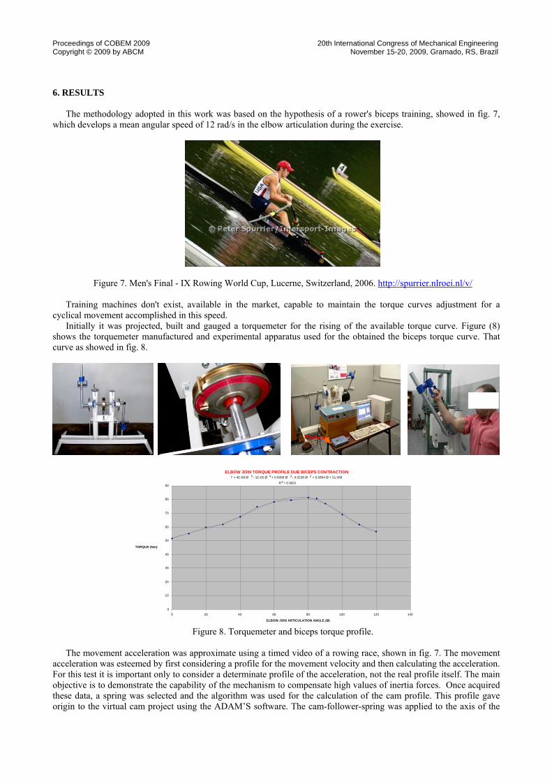
6. RESULTS
The methodology adopted in this work was based on the hypothesis of a rower's biceps training, showed in fig. 7, which develops a mean angular speed of 12 rad/s in the elbow articulation during the exercise.
Figure 7. Men's Final - IX Rowing World Cup, Lucerne, Switzerland, 2006. http://spurrier.nlroei.nl/v/
Training machines don't exist, available in the market, capable to maintain the torque curves adjustment for a cyclical movement accomplished in this speed.
Initially it was projected, built and gauged a torquemeter for the rising of the available torque curve. Figure (8) shows the torquemeter manufactured and experimental apparatus used for the obtained the biceps torque curve. That curve as showed in fig. 8.
Figure 8. Torquemeter and biceps torque profile. The movement acceleration was approximate using a timed video of a rowing race, shown in fig. 7. The movement
acceleration was esteemed by first considering a profile for the movement velocity and then calculating the acceleration. For this test it is important only to consider a determinate profile of the acceleration, not the real profile itself. The main objective is to demonstrate the capability of the mechanism to compensate high values of inertia forces. Once acquired these data, a spring was selected and the algorithm was used for the calculation of the cam profile. This profile gave origin to the virtual cam project using the ADAM’S software. The cam-follower-spring was applied to the axis of the
Entra
ELBOW JOIN TORQUE PROFILE DUE BICEPS CONTRACTIONT = 4E-08 Ø 5 - 1E-05 Ø 4 + 0.0008 Ø 3 - 0.0238 Ø 2 + 0.5864 Ø + 51.568
R2 = 0.9931
0
10
20
30
40
50
60
70
80
90
0 20 40 60 80 100 120 140 ELBOW JOIN ARTICULATION ANGLE (Ø)
TORQUE (Nm)

torquemeter, taking advantage of its knowledge moment of inertia. So, the moment of inertia of the system group can be easily determined. Figure 9 show the proposed model using the ADAM’S software.
The cam moment of inertia was previously obtaining, however, the maintenance of the moment of inertia for definitive piece by adjusting its thickness is simple.
Figure 9. The mechanism project using ADAM’S software.
Finally, the virtual project of mechanism was tested applying the available torque to the main axis and comparing the resulting acceleration with the previously adjusted acceleration, as shown in Fig. 10.
Figure 10. ADAMS test results showing the model velocity and acceleration due application of the available torque.
In the current apprenticeship, a real model of the mechanism is being built and will be set up in the torquemeter
chassis for a direct gauging. It is waited to obtain the validation of experimental model so that this can be used in future project of appropriate dispositive for any muscular group workout. Figure (11) shows the proposed device to muscle training.

Proceedings of COBEM 2009 20th International Congress of Mechanical Engineering Copyright © 2009 by ABCM November 15-20, 2009, Gramado, RS, Brazil
Figure 11. Mechanism operation outline.
7. CONCLUSIONS The mechanism was designed to prevent the inertia effect, first substituting masses by the spring-cam-follower
system of less inertia and second, modifying the cam profile to increase or to diminish the resistant torque generated by the spring according to inertia forces in a specific exercise. In such a way, the resistant torque is kept proportional to the muscle capacity during all the movement, since that the acceleration and movement speeds are maintained in accordance to the predetermined pattern of movement.
For this system, this pattern can involve high speed and acceleration for training movements that match better to each case, according to Specificity Principle.
Another advantage would be the reduction of injuries risk in transition of the eccentric phase to the concentric phase of movement.
8. ACKNOWLEDGMENTS The Mechanical Projects Laboratory Prof. Henner A. Gomide (LPM)/UFU and the CNPq and FAPEMIG for the
financial support.
9. REFERENCES Hall, Suzan, “Biomecânica Básica”, Editora Guanabara Kogan, 1999. Gallagher, J., & DeLorme, T. (1949). “The use of progressive resistance exercise in adolescence”. The Journal of Bone
and Joint Surgery. 31-A (4), 847-858. McCafferty WB, Horvath SM, “Specificity of exercise and specificity of training: a subcellular review”, 1977 May,
Research Quarterly. 48: 358-371. Zatsiorsky VM, “Biomecânica no Esporte: Performance do Desempenho e Prevenção de Lesão”, Editora Guanabara
Kogan, 2004. M. Kloomok e R. V. Muffley, “Plate Cam Design – Pressure Angle Analysis”, Prod. Eng.,Maio 1955. Guyton, a & Hall, J. E, “Tratado de Fisiologia Médica”, 9ª edição, Guanabara Koogan, 1997. Hollmann, w. & Hettinger, th., “Medicina de Esporte”. São Paulo, Manole, 1989. McArdle, William D. & Frank I. Katch & Victor L. Katch, “Fisiologia do Exercício: Energia, Nutrição e Desempenho
Humano”, Guanabara Koogan, 1996. Fox, Edward L. et ali, “Bases Fisiológicas da Educação Física e dos Desportos”, Guanabara Koogan, 1990. Roger M. Enoka, “Bases Biomecânicas da Cinesiologia”, Segunda Edição, Editora Manole, 2000. 10. RESPONSIBILITY NOTICE
The authors are the only responsible for the printed material included in this paper.