inelastic behaviour of bacterial cellulose hydrogel: … · inelastic behaviour of bacterial...
TRANSCRIPT

Loughborough UniversityInstitutional Repository
Inelastic behaviour ofbacterial cellulose hydrogel:
in aqua cyclic tests
This item was submitted to Loughborough University's Institutional Repositoryby the/an author.
Citation: GAO, X. et al., 2015. Inelastic behaviour of bacterial cellulose hy-drogel: in aqua cyclic tests. Polymer Testing, 44, pp. 82 - 92
Additional Information:
• This paper was accepted for publication in the journal Poly-mer Testing and the definitive published version is available athttp://dx.doi.org/10.1016/j.polymertesting.2015.03.021
Metadata Record: https://dspace.lboro.ac.uk/2134/17833
Version: Accepted for publication
Publisher: c© Elsevier Ltd
Rights: This work is made available according to the conditions of the Cre-ative Commons Attribution-NonCommercial-NoDerivatives 4.0 International(CC BY-NC-ND 4.0) licence. Full details of this licence are available at:https://creativecommons.org/licenses/by-nc-nd/4.0/
Please cite the published version.

Inelastic behaviour of bacterial cellulose hydrogel: In aqua cyclic tests Xing Gao 1, Zhijun Shi 2, Changqing Liu 1, Guang Yang 2, Igor Sevostianov 3 and Vadim V. Silberschmidt 1
1 Wolfson School of Mechanical and Manufacturing Engineering, Loughborough University, Loughborough, UK 2 College of Life Science and Technology, Huazhong University of Science and Technology, Wuhan, China 3 Department of Mechanical and Aerospace Engineering, New Mexico State University, Las Cruces, USA
* Corresponding author; E-mail: [email protected]
Abstract
Hydrogels are finding an increasingly broad use, especially in biomedical applications. Their complex structure – a low-density network of microfibrils – defines their non-trivial mechanical behaviour. The focus of this work is on test-based quantification of mechanical behaviour of a bacterial cellulose (BC) hydrogel exposed to cyclic loading. Specimens for the tests were produced using Gluconacetobacter xylinus ATCC 53582 and tested in aqua under uniaxial cyclic loading conditions in a displacement-controlled regime. Substantial microstructural changes were observed in the process of deformation. A combination of qualitative microstructural observations with quantitative force-displacement relations allowed identification of main deformation mechanisms, confirming inelastic behaviour of BC hydrogel under a loading-unloading-reloading regime. Elastic deformation was accompanied by non-elastic (viscoplastic) deformation in both tension and compression. This study also aims to establish a background for micromechanical modelling of overall properties of BC hydrogels.
Key words: inelastic behaviour; bacterial cellulose hydrogel; in aqua mechanical testing; deformation mechanisms; cyclic tension and compression
1. Introduction
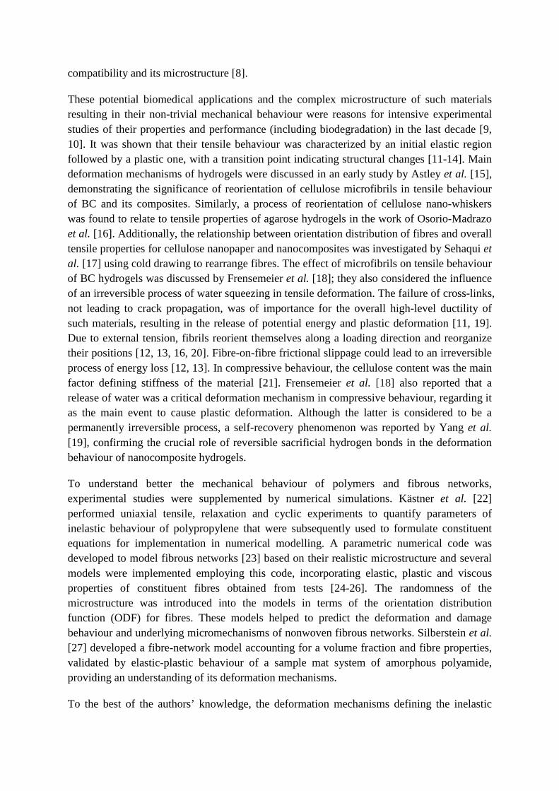
Bacterial cellulose (BC) hydrogel is obtained as a product of certain bacteria (e.g. Acetobacter, Rhizobium, Agrobacterum and Sarcina); structurally, it be can generally regarded as a multi-layer scaffold with non-woven fibrous structure absorbing large amounts of interstitial water (99 vol%), see Figs. 1a-1c. Such materials are being increasing sought for biomedical applications [1]; BC hydrogels can be used for artificial blood vessels [2], ear cartilage implants [3], encasement for tissue regeneration [4-7], etc. The main advantages of a BC hydrogel, allowing using it in these biomedical applications, are its perfect biological
compatibility and its microstructure [8].
These potential biomedical applications and the complex microstructure of such materials resulting in their non-trivial mechanical behaviour were reasons for intensive experimental studies of their properties and performance (including biodegradation) in the last decade [9, 10]. It was shown that their tensile behaviour was characterized by an initial elastic region followed by a plastic one, with a transition point indicating structural changes [11-14]. Main deformation mechanisms of hydrogels were discussed in an early study by Astley et al. [15], demonstrating the significance of reorientation of cellulose microfibrils in tensile behaviour of BC and its composites. Similarly, a process of reorientation of cellulose nano-whiskers was found to relate to tensile properties of agarose hydrogels in the work of Osorio-Madrazo et al. [16]. Additionally, the relationship between orientation distribution of fibres and overall tensile properties for cellulose nanopaper and nanocomposites was investigated by Sehaqui et al. [17] using cold drawing to rearrange fibres. The effect of microfibrils on tensile behaviour of BC hydrogels was discussed by Frensemeier et al. [18]; they also considered the influence of an irreversible process of water squeezing in tensile deformation. The failure of cross-links, not leading to crack propagation, was of importance for the overall high-level ductility of such materials, resulting in the release of potential energy and plastic deformation [11, 19]. Due to external tension, fibrils reorient themselves along a loading direction and reorganize their positions [12, 13, 16, 20]. Fibre-on-fibre frictional slippage could lead to an irreversible process of energy loss [12, 13]. In compressive behaviour, the cellulose content was the main factor defining stiffness of the material [21]. Frensemeier et al. [18] also reported that a release of water was a critical deformation mechanism in compressive behaviour, regarding it as the main event to cause plastic deformation. Although the latter is considered to be a permanently irreversible process, a self-recovery phenomenon was reported by Yang et al. [19], confirming the crucial role of reversible sacrificial hydrogen bonds in the deformation behaviour of nanocomposite hydrogels.
To understand better the mechanical behaviour of polymers and fibrous networks, experimental studies were supplemented by numerical simulations. Kästner et al. [22] performed uniaxial tensile, relaxation and cyclic experiments to quantify parameters of inelastic behaviour of polypropylene that were subsequently used to formulate constituent equations for implementation in numerical modelling. A parametric numerical code was developed to model fibrous networks [23] based on their realistic microstructure and several models were implemented employing this code, incorporating elastic, plastic and viscous properties of constituent fibres obtained from tests [24-26]. The randomness of the microstructure was introduced into the models in terms of the orientation distribution function (ODF) for fibres. These models helped to predict the deformation and damage behaviour and underlying micromechanisms of nonwoven fibrous networks. Silberstein et al. [27] developed a fibre-network model accounting for a volume fraction and fibre properties, validated by elastic-plastic behaviour of a sample mat system of amorphous polyamide, providing an understanding of its deformation mechanisms.
To the best of the authors’ knowledge, the deformation mechanisms defining the inelastic
behaviour of BC hydrogels have never been systematically studied in the literature. As a result, this hinders simulation-based assessment of their overall properties and performance and prediction mechanical behaviour of components made from hydrogels under application-relevant conditions. In this paper, the main focus is on this issue. The inelastic behaviour of the BC hydrogel was studied `by performing incremental cyclic tension and compression tests. The entire process of cyclic deformation was divided into loading, unloading and reloading regimes, with each regime discussed separately. Field-emission-gun scanning electron microscopy (FEG-SEM) was employed to identify microstructural changes induced by macroscopic deformation of the hydrogel.
2. Material and method
2.1. Synthesis of bacterial cellulose hydrogel
Figure 1: (a) Disk sample of bacterial cellulose hydrogel in natural state. SEM images (5000×) of freeze-dried BC hydrogel show a random distribution of BC fibres within fibre-layer (b) and some fibres playing a role of cross-linking to connect fibrous layers (c).
To produce a hydrogel for this study, Gluconacetobacter xylinus ATCC 53582 (American Type Culture Collection, Manassas, VA, USA) was inoculated and cultured at 30 °C in a static culture medium which contained 2% (w/v) glucose, 0.5% (w/v) yeast extract powder, 0.5% (w/v) peptone, 0.27% (w/v) disodium phosphate (Na2HPO4), and 0.115% (w/v) citric acid for 7 days. Then, samples of the BC hydrogel were treated by boiling 0.1 M NaOH for 30 min to eliminate bacterial and protein impurities. Subsequently, they were rinsed with distilled water until a pH level of 7.0 was reached. Next, the BC hydrogel was washed several times with high-purity water and stored in this water at 4°C.
2.2. Specimen preparation
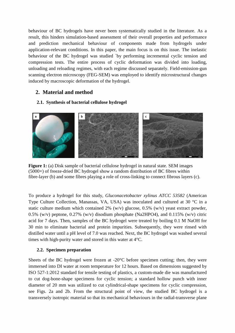
Sheets of the BC hydrogel were frozen at -20°C before specimen cutting; then, they were immersed into DI water at room temperature for 12 hours. Based on dimensions suggested by ISO 527-1:2012 standard for tensile testing of plastics, a custom-made die was manufactured to cut dog-bone-shape specimens for cyclic tension; a standard hollow punch with inner diameter of 20 mm was utilized to cut cylindrical-shape specimens for cyclic compression, see Figs. 2a and 2b. From the structural point of view, the studied BC hydrogel is a transversely isotropic material so that its mechanical behaviours in the radial-transverse plane
(in plane of layers) and out-of-plane (perpendicular to layers) are independent. Additionally, it is apparent that tensile behaviour in the out-of-plane direction and compressive behaviour in the radial-transverse plane are less important, since they can be hardly realised in applications. Hence, two main loading states – tension in the radial-transverse plane and compression along the out-of-plane direction – were used in this study, and specimens for cyclic tests were manufactured accordingly (see Fig. 2a).
Figure 2: (a) Cut BC hydrogel sheet after extraction of dog-bone-shape and cylindrical specimens; (b) dimensions of dog-bone-shape specimen for tension and cylindrical specimens for compression; (c) schematic diagram of radial, transverse and out-of-plane directions
2.3. Mechanical testing
All the tests were performed in aqua, to reproduce conditions typical for potential applications. Hence, a BioPuls system with a feedback temperature controller (Instron 3130-100 BioPuls Bath, Instron, USA) (Fig. 3a-3b) was used. It provided an aqueous testing environment at a constant temperature of 37.0±1.0°C. Matching submergible grips and custom-made compression platens were used to hold tensile specimens and to place compression specimens, respectively (Figs. 3c-3d). Due to the floppy texture of BC hydrogel, a pre-load of 0.05 N was applied both in tension and compression. An Instron 3366 testing machine (Instron 3366 Computerised Universal Testing Machine, Instron, USA) was used for quasi-static tensile and compressive tests. The forces measured with a load cell (2530 Series Low-profile Static Load Cell, Instron, USA) were in the range to 100 N in tension and 500 N in compression. A crosshead displacement sensor was utilized to provide deformation measurements.
Incremental cyclic tension and compression tests were performed at strain rate of 0.001 s-1 for both loading and unloading processes. In the case of in-aqua testing, with the liquid providing buoyancy, the grips or platens would return to their initial positions if the test-end criterion of the unloading process is chosen as a zero force, leading to buckling and producing artificial data at the end of the unloading phase. To avoid this in tensile tests, specimens (n = 5) were stretched to the nine pre-defined incremental stress levels, ranging from 5% to 80% of the ultimate stress (1.43 MPa for the studied hydrogel), then returned to a stress of 0.05 MPa at the end of unloading. In compression, since the low-density BC hydrogel cannot demonstrate the ultimate stress along the out-of-plane direction, specimens (n = 5) were compressed to the twenty pre-defined incremental levels of compressive force,

ranging from 0.5 N to 180 N, then returned in the unloading stage to a compressive force of 0.2 N.
Figure 3: (a) BioPlus system; (b) feedback temperature controller; (c) submersible grips for tensile specimens; (d) custom-made platens for compressive specimens
2.4. Microscopic morphology analysis
The real-time study of microstructural changes in the process of in-aqua testing is technically very challenging. Thus, in the present study, the residual microstructure after stretching was used to observe deformation-induced microstructural changes. The specimens were first stretched to 40% strain. Then, a custom-made fixture was used to fix the stretched specimens for microstructural analysis (Fig. 4a-ab); the specimen without fixture was used to observe the microstructure after release of a stretching load. Next, water in specimens was removed by freeze-drying (Fig. 4c). Finally, the gauge length of specimens was cut into several samples (Fig. 4d) for micro-morphology analysis using field-emission-gun scanning electron microscopy.
Figure 4: (a) custom-made fixture to fix stretched tensile specimen during tensile test to avoid elastic springback and reversed microstructural changes; (b) tensile specimen before freeze-drying; (c) tensile specimen after freeze-drying; (d) cut samples for FEG-SEM analysis
3. Results
3.1. Loading-unloading-reloading behaviour
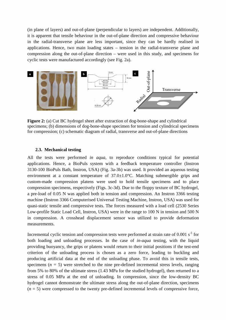
Cyclic tension An averaged stress-strain curve of the studied BC hydrogel under incremental cyclic tension presented in Fig. 5a demonstrates non-trivial mechanical behaviour. To quantify it properly, three parameters – loading modulus, unloading modulus and reloading modulus – are introduced in this study, presenting, correspondingly, tangent moduli 𝐸 in loading, unloading and reloading stages of the tests; they are calculated as the ratios of stress and
strain differentials for the obtained data points. The evolution of these parameters with strain was obtained numerically, see Fig. 5b. Since the data points of the first cycle are insufficient to demonstrate a clear tendency, the respective moduli are not shown in Fig. 5b. In order to clarify the main trends, two types of evolution of the three moduli are shown in Fig. 5c. The dependence of loading, unloading and reloading moduli on strain is presented in Figs. 5d-5f. The following observations can be made from the analysis of Fig. 5.
i. In Fig. 5a, the BC hydrogel demonstrates non-linear behaviour at all stress levels for loading, unloading and reloading regimes.
ii. The unloading curve did not return to the initial state, showing that the hydrogel demonstrated inelastic deformation even at the smallest stress level (see the inset in Fig. 5a) and, subsequently, at small strains.
iii. The difference between the unloading and reloading curves in the form of a hysteretic loop indicates viscoelastic deformational behaviour (Fig. 5a).
iv. The evolution of loading, unloading and reloading moduli shows non-linear dependence on strain (Figs. 5d-f)
v. The unloading modulus 𝐸U decreases with strain; this dependence can be approximated with a bi-linear curve (Fig. 5e).
vi. Evolution of the reloading modulus is a two-step process – increasing and then decreasing – resulted in a S-shaped reloading stress-strain curves that can be generally approximated with a tri-linear curve (Fig. 5f).
vii. The final portion of the evolution curves for the unloading and reloading moduli was approaching the levels of the loading modulus for the same strain; see marked regions in Fig. 5c.
viii. Interestingly, the overlapping parts of the curves for the unloading and reloading moduli correspond with the maximum tangent modulus in the reloading process (Fig. 5c).
Figure 5: (a) Averaged stress-strain curve for BC specimens under incremental cyclic tensile loading at strain rate of 0.001 s-1; (b) and (c) evolution of averaged unloading and reloading
moduli curve with strain; (d) evolution of loading modulus with strain; (e) evolution of unloading modulus with strain; (f) evolution of reloading modulus with strain
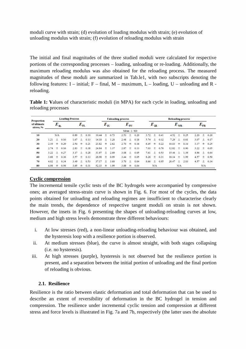
The initial and final magnitudes of the three studied moduli were calculated for respective portions of the corresponding processes – loading, unloading or re-loading. Additionally, the maximum reloading modulus was also obtained for the reloading process. The measured magnitudes of these moduli are summarized in Tab.le1, with two subscripts denoting the following features: I – initial; F – final, M – maximum, L – loading, U – unloading and R - reloading.
Table 1: Values of characteristic moduli (in MPA) for each cycle in loading, unloading and reloading processes
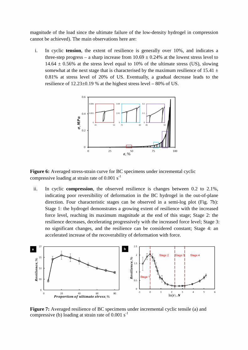
Cyclic compression The incremental tensile cyclic tests of the BC hydrogels were accompanied by compressive ones; an averaged stress-strain curve is shown in Fig. 6. For most of the cycles, the data points obtained for unloading and reloading regimes are insufficient to characterise clearly the main trends, the dependence of respective tangent moduli on strain is not shown. However, the insets in Fig. 6 presenting the shapes of unloading-reloading curves at low, medium and high stress levels demonstrate three different behaviours:
i. At low stresses (red), a non-linear unloading-reloading behaviour was obtained, and the hysteresis loop with a resilience portion is observed.
ii. At medium stresses (blue), the curve is almost straight, with both stages collapsing (i.e. no hysteresis).
iii. At high stresses (purple), hysteresis is not observed but the resilience portion is present, and a separation between the initial portion of unloading and the final portion of reloading is obvious.
2.1. Resilience
Resilience is the ratio between elastic deformation and total deformation that can be used to describe an extent of reversibility of deformation in the BC hydrogel in tension and compression. The resilience under incremental cyclic tension and compression at different stress and force levels is illustrated in Fig. 7a and 7b, respectively (the latter uses the absolute
magnitude of the load since the ultimate failure of the low-density hydrogel in compression cannot be achieved). The main observations here are:
i. In cyclic tension, the extent of resilience is generally over 10%, and indicates a three-step progress – a sharp increase from 10.69 ± 0.24% at the lowest stress level to 14.64 ± 0.56% at the stress level equal to 10% of the ultimate stress (US), slowing somewhat at the next stage that is characterised by the maximum resilience of 15.41 ± 0.81% at stress level of 20% of US. Eventually, a gradual decrease leads to the resilience of 12.23±0.19 % at the highest stress level – 80% of US.
Figure 6: Averaged stress-strain curve for BC specimens under incremental cyclic compressive loading at strain rate of 0.001 s-1
ii. In cyclic compression, the observed resilience is changes between 0.2 to 2.1%, indicating poor reversibility of deformation in the BC hydrogel in the out-of-plane direction. Four characteristic stages can be observed in a semi-log plot (Fig. 7b): Stage 1: the hydrogel demonstrates a growing extent of resilience with the increased force level, reaching its maximum magnitude at the end of this stage; Stage 2: the resilience decreases, decelerating progressively with the increased force level; Stage 3: no significant changes, and the resilience can be considered constant; Stage 4: an accelerated increase of the recoverability of deformation with force.
Figure 7: Averaged resilience of BC specimens under incremental cyclic tensile (a) and compressive (b) loading at strain rate of 0.001 s-1

2.2. Microstructural changes in tension
Microstructure of the specimen stretched to a strain level of 40% is shown in Fig. 8a. As a result of tensile loading, a number of fibres re-orientated along the loading direction compared to their random distribution in the natural (initial) state shown in Fig. 1b. However, the direction of a small group of fibres is inclined with regard to the loading direction at large angle (sometimes, they are even perpendicular to it). Noticeably, some fibres, orientated in different directions, are assembled in entanglements, with the size significantly larger than the fibre diameter (circular marks in Fig. 8a). As a result, long fibres are divided into fragments connecting by these entanglements, forming an interweaved network of cells of mostly polygonal shape (Figs. 8a-8b). After load removal, these entanglements are still present, as seen from Fig. 8c. However, a reversed process of deformation affected the microstructure by relieving some of its orientation-dependence due to the applied load: the extent of fibre-realignment is less prominent, and the polygons of the network cells became less stretched (and more round) (Fig. 8c-d).
Figure 8: SEM images (5000×) and schematic diagrams of re-arranged microstructures of BC specimen fixed ((a) and (b)) and released ((c) and (d)) after 40% strain stretching
3. Discussion
The deformation behaviour of the BC hydrogel studied under conditions of incremental cyclic tension and compression demonstrates its inelastic character effectively at all the stress levels. No yield point and pure elastic region were observed in contrast with the study by Sehaqui and Das [9, 10]. This behaviour is rather non-trivial and needs several parameters for its quantification. Such an extent of complexity is related to specific microstructure of the hydrogels and its changes in loading, unloading and reloading.
In cyclic tension, six main mechanisms of deformation (denoted with 𝑀𝑖 with a respective
index) were identified: (a) re-orientation of fibres (𝑀1); (b) interaction of fibres (𝑀2); (c) interaction between entanglements (𝑀3 ); (d) deflection of molecule chains (𝑀4 ); (e) elongation of covalent bond of molecule chains (𝑀5); (f) prevention fibre movement by interstitial water (𝑀6). In addition, in the natural (non-deformed) state, BC fibres formed a pattern of interlace weave [7]. The schematic diagram of loading-unloading-reloading process in tension is presented in Fig. 9, and the inelastic behaviour can be described as the following sequence:
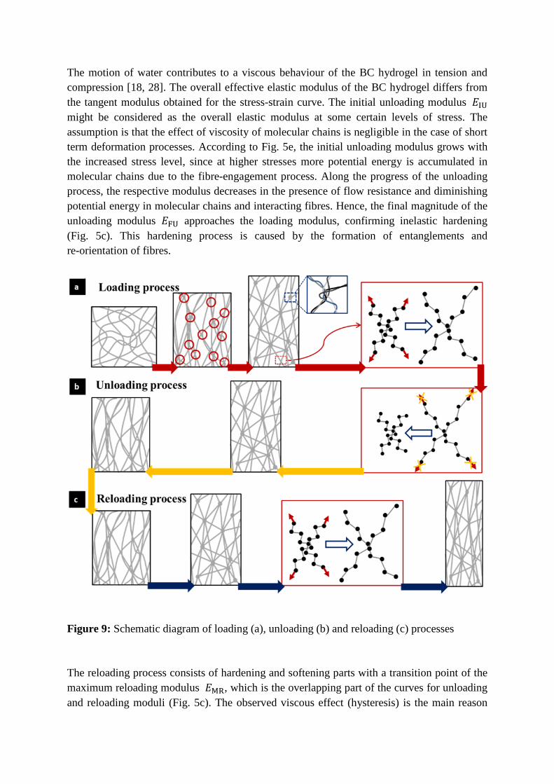
i. In the natural state, fibres in the BC hydrogel are randomly distributed and mostly free of constraints (Fig. 1b). When tensile loading is applied to a specimen, fibres attempt to re-orientate themselves towards the loading direction (𝑀1). During the re-orientation process, fibres are easily twisted and interlace with each other forming knots, termed entanglements [18], see Fig. 8a ( 𝑀2 ). Then, with increased stretching, these entanglements cause straightening of the fragments of fibres attached to them, deflecting them from the loading direction orientation (𝑀3 ). When the fragments are fully constrained, viscoelasticity of molecular chains plays the major role in load-bearing. Hence, potential energy is equivalent to the energy stored in the molecular bonds plus the energy required to change the molecular angle (𝑀4 + 𝑀5). The increasing number of fully constrained molecular chains results in a stiffer overall behaviour. Interstitial water, with its low compressibility, resists motion of fibres (𝑀6) and is squeezed out from the fibrous network in the process of lateral shrinkage.
ii. In unloading, the potential energy accumulated in molecular chains is first released (𝑀4 + 𝑀5). Kinematically, during the reverse motion of molecular chains, fully loaded fragments of fibres attempt to pull entanglements to reduce constraints (𝑀3 ), and spontaneously move to a position providing a decrease in potential energy (𝑀2). The process results in the rearrangement of fibres in the network, in the form of reorientation of fibres and changes in the shape of network cells, as shown in Fig. 8b. At the same time, water resists the reverse movement of straightened and interacted fibres (𝑀5). Once the entanglement are formed, fibres cannot reverse fully to their initial position (natural distribution) because of the knots formed (Fig. 8c). The process of formation of these entanglements is the main reason that no pure elastic region was observed in the studied hydrogel.
iii. The reloading process is mostly an inverse of the unloading one. So, the initial portion of the reloading process involves re-orientation of fragments of fibres and interaction between entanglements (𝑀2 + 𝑀3). Elongation of fibres plays the main role in the increase in deformation (𝑀4 + 𝑀5).
The positive effect on resilience in tension is the increasing number of stretched fragments. As strain increases, failure of a single fibre may occur, not leading to failure of the bulk material since the microcrack cannot propagate through a discontinuous matrix. The negative effect on resilience in tension is the increasing number of fibre failures (mcirocracking). The non-trivial realisation of resilience process in tension with the increased stress level is the result of competition of these two effects (Fig. 7a).
The motion of water contributes to a viscous behaviour of the BC hydrogel in tension and compression [18, 28]. The overall effective elastic modulus of the BC hydrogel differs from the tangent modulus obtained for the stress-strain curve. The initial unloading modulus 𝐸IU might be considered as the overall elastic modulus at some certain levels of stress. The assumption is that the effect of viscosity of molecular chains is negligible in the case of short term deformation processes. According to Fig. 5e, the initial unloading modulus grows with the increased stress level, since at higher stresses more potential energy is accumulated in molecular chains due to the fibre-engagement process. Along the progress of the unloading process, the respective modulus decreases in the presence of flow resistance and diminishing potential energy in molecular chains and interacting fibres. Hence, the final magnitude of the unloading modulus 𝐸FU approaches the loading modulus, confirming inelastic hardening (Fig. 5c). This hardening process is caused by the formation of entanglements and re-orientation of fibres.
Figure 9: Schematic diagram of loading (a), unloading (b) and reloading (c) processes
The reloading process consists of hardening and softening parts with a transition point of the maximum reloading modulus 𝐸MR, which is the overlapping part of the curves for unloading and reloading moduli (Fig. 5c). The observed viscous effect (hysteresis) is the main reason

for the initial reloading modulus 𝐸𝐼𝐼 being higher than the final unloading modulus 𝐸FU (Tab. 1). Re-orientation of fragments of fibres in reloading leads to hardening. Then, the stress-strain and modulus curves for reloading are approaching the master curve due to viscosity of fibres. The maximum reloading modulus is the point of balance of the two competing mechanisms in the reloading behaviour.
In cyclic compression, three different types of unloading-reloading behaviour were observed for low-, medium- and high-strain ranges. A high content of interstitial water is in the space between fibre layers (Fig. 1c), and it can be easily squeezed out [19, 28]. The weak cross-links are insufficient to support layers of fibres in re-absorption of squeezed water, leading to poor resilience in compression at all force levels (Fig. 7b). The main feature of deformation and related microstructural changes in three compression types are:
i. At low strains, the compressive load attempts to press interstitial water out as a result of decreasing space between the layers of fibres. At the same time, the cross-links between the layers start bearing the load in the form of bending or buckling, resulting in a hysteresis effect with a resilience part. More potential energy is stored along the progress of bending or buckling, acting as a positive effect on resilience. Since the cross-links are not fully perpendicular to the loading direction, they would re-orientate themselves towards the plane of fibre-layers, providing lower resistance to external loading and, thus, reducing resilience. Hence, a dependence of the resilience on the force level is governed by these two competing processes (Stages 1 and 2 in Fig. 7b).
ii. At medium strains, interstitial water between the layers of fibre is almost squeezed out, and the layers are compacted together with the cross-links almost in the layers’ plane. The compressive load continues compacting the fibres within the layers. In the absence of cross-links, this process is almost irreversible, with a constant minimum value of resilience, as observed on the experimental unloading-reloading curve (Stage 3 in Fig. 7b).
iii. At high strains, the fibres are already compacted together. The compressive load attempts to press fibres more, filling the gaps between them. As a result, the fibrous network becomes a thin layer. The load continuing to acts on the layer will result in a sharp increase of the measured force, the resistance of which is significantly higher than that of cross-links. As a result, a separation between the initial portion of unloading and the final portion of reloading can be observed (see the purple inset in Fig. 6). This compression of the thin layer of fibres is mostly elastic since their bulk material responds to the load. Hence, the inelastic deformation is prominent at stages preceding the high-strain range. As a result, the resilience would increase with the increased deformation corresponding to the growing force level at high strains (Stage 4 in Fig. 7b).
4. Conclusions
This work provides a thorough experimental study of the main deformation mechanisms and microstructural changes in a bacterial cellulose hydrogel exposed to in aqua cyclic tension and compression loading conditions. The main aim was to use this analysis to elucidate inelastic behaviour of the hydrogel. The obtained results demonstrate different realisations of
inelastic deformation in loading, unloading and reloading regimes; they are related to respective underpinning microstructural mechanisms. As a result of such complicated deformational behaviour, six tangential moduli were used to quantify these three regimes. Evolution of the moduli with stress (extent of stretching or compression) provides insights into the development of inelastic deformation in the hydrogel. It is enhanced by the analysis of characteristic trends for resilience both in tension and compression. The main deformation mechanisms are discussed for the loading, unloading and reloading processes separately, based on the performed mechanical tests and micro-morphological observations of various states of the hydrogel with FEG-SEM. The formation of entanglements and rearrangement of fragments of fibres connecting them was observed under external tension. Apparently, they are the main factors causing inelastic deformation even at the initial stages of loading. The studied behaviour – alongside the quantitative data for the moduli – provides the foundation for numerical modelling, which will be implemented in the future.
Acknowledgement The authors would like to acknowledge the 7th European Community Framework Programme for financial support through a Marie Curie International Research Staff Exchange Scheme (IRSES) Projects TAMER (Grant PIRSES-GA-2013-610547) and M6 (Grant No. PIRSES-GA-2010-269113). Additional support from the China-European Union technology cooperation programme (Grant No. 1110) is also acknowledged.
References
1. M. Irani, H. Ismail, Z. Ahmad. Preparation and properties of linear low-density polyethylene-g-poly (acrylic acid)/organo-montmorillonite superabsorbent hydrogel composites, Polym Test 2013;32(3):502
2. C. J.Malm, B. Risberg, A. Bodin, H. Bäckdahl, B. R. Johansson, P. Gatenholm, A. Jeppsson. Small calibre biosynthetic bacterial cellulose blood vessels: 13-months patency in a sheep model. Scand Cardiovasc J 2012;46:57
3. L. Nimeskern, H. Martínez Ávila, J. Sundberg, P. Gatenholm, R. Müller, K.S. Stok. Mechanical evaluation of bacterial nanocellulose as an implant material for ear cartilage replacement. J Mech Behav Biomed Mater 2013;22:12
4. H. Bäckdahl, M. Esguerra, D. Delbro, B. Risberg, P. Gatenholm. Engineering microporosity in bacterial cellulose scaffolds. J Tissue Eng Regen Med 2008;2(6):320
5. H. Bäckdahl, G. Helenius, A. Bodin, U. Nannmark, B. R. Johansson, B. Risberg, P. Gatenholm. Mechanical properties of bacterial cellulose and interactions with smooth muscle cells. Biomater 2006;27(9):2141
6. I. Gibas, H. Janik. Review: synthetic polymer hydrogels for biomedical applications. Chem Chem Technol 2010;4(4):297
7. K. Kowalska-Ludwicka, J. Cala, B. Grobelski, D. Sygut, D. Jesionek-Kupnicka, M. Kolodziejczyk, S. Bielecki, Z. Pasieka. Modified bacterial cellulose tubes for regeneration of damaged peripheral nerves. Arch Med Sci 2013;9:527
8. Z. Shi, Y. Zhang, G. O. Phillips, G. Yang. Utilization of bacterial cellulose in food. Food Hydrocoll 2014;35:539
9. M. Matsui, L. Ono, L. Akcelrud. Chitin/polyurethane networks and blends: Evaluation of biological application. Polym Test 2012;31(1):191
10. D. M. Correia, J. Padrão, L. R. Rodrigues, F. Dourado, S. Lanceros-Méndez, V. Sencadas, Thermal and hydrolytic degradation of electrospun fish gelatin membranes. Polym Test 2013;32(5):995
11. S. S.Nair, J. Y. Zhu, Y. Deng, A. J. Ragauskas. Hydrogels prepared from cross-linked nanofibrillated cellulose. ACS Sustain Chem Eng 2014;2:772
12. H. Sehaqui, S. Morimune, T. Nishino, L. A. Berglund. Stretchable and strong cellulose nanopaper structures based on polymer-coated nanofiber networks: An alternative to nonwoven porous membranes from electrospinning. Biomacromol 2012;13:3661
13. P. Das, T. Heuser, A. Wolf, B. Zhu, D. E. Demco, S. Ifuku, A. Walther. Tough and catalytically active hybrid biofibers wet-spun from nanochitin hydrogels. Biomacromol 2012;13:4205
14. J. Malho, P. Laaksonen, A. Walther, O. Ikkala, M. B. Linder. Facile method for stiff, tough, and strong nanocomposites by direct exfoliation of multilayered graphene into native nanocellulose matrix. Biomacromol 2012;13:1093
15. O. M. Astley, E. Chanliaud, A. M. Donald, M. J. Gidley. Tensile deformation of bacterial cellulose composites. Int J Biol Macromol 2003;32:28
16. A. Osorio-Madrazo, M. Eder, M. Rueggeberg, J. K. Pandey, M. J. Harrington, Y. Nishiyama, J. Putaux, C. Rochas, I. Burgert. Reorientation of cellulose nanowhiskers in agarose hydrogels under tensile loading. Biomacromol 2012;13:850
17. H. Sehaqui, N. E. Mushi, S. Morimune, M. Salajkova, T. Nishino, L. A. Berglund. Cellulose nanofiber orientation in nanopaper and nanocomposites by cold drawing. ACS Appl Mater Interfaces 2012;4:1043
18. M. Frensemeier, C. Koplin, R. Jaeger, F. Kramer, D. Klemm. Mechanical properties of bacterially synthesized nanocellulose hydrogels. Macromol Symp 2010;294:38
19. J. Yang, C. Han, J. Duan, F. Xu, R. Sun. Mechanical and viscoelastic properties of cellulose nanocrystals reinforced poly(ethylene glycol) nanocomposite hydrogels. ACS Appl Mater Interfaces 2013;5:3199
20. S. Naficy, H. R. Brown, J. M. Razal, G. M. Spinks, P. G. Whitten. Progress toward robust polymer hydrogels. Aust J Chem 2010;64:1007
21. A. L. Buyanov, I. V. Gofman, A. K. Khripunov, A. A. Tkachenko, E. E. Ushakova. High-strength biocompatible hydrogels based on poly(acrylamide) and cellulose:
Synthesis, mechanical properties and perspectives for use as artificial cartilage. Polym Sci Ser A 2013;55:302
22. K. Kästner, M. Obst, J. Brummund, K. Thielsch, V. Ulbricht. Inelastic material behavior of polymers – Experimental characterization, formulation and implementation of a material model. Mech Mater 2012;52:40
23. B. Sabuncuoglu, M. Acar, V. V. Silberschmidt. Finite element modelling of fibrous networks: Analysis of strain distribution in fibres under tensile load. Comput Mater Sci 2013;79:143
24. B. Sabuncuoglu, M. Acar, V. V. Silberschmidt. Parametric code for generation of finite-element model of nonwovens accounting for orientation distribution of fibres. Int J Numer Meth Engng 2013;94(5):441
25. F. Farukh, E. Demirci, B. Sabuncuoglu, M. Acar, B. Pourdeyhimi, V. V. Silberschmidt. Numerical analysis of progressive damage in nonwoven fibrous networks under tension. Int J Solids Struct 2014;51(9):1670
26. F. Farukh, E. Demirci, B. Sabuncuoglu, M. Acar, B. Pourdeyhimi, V. V. Silberschmidt. Numerical modelling of damage initiation in low-density thermally bonded nonwovens. Comp Mater Sci 2012;64:112
27. M. N. Silberstein, C. Pai, G. C. Rutledge, M. .C. Boyce, Elastic–plastic behaviour of non-woven fibrous mats, J Mech Phys Solids 2012;60:295
28. P. Lopez-Sanchez, M. Rincon, D. Wang, S. Brulhart, J. R. Stokes, M. J. Gidley. Micromechanics and poroelasticity of hydrated cellulose networks. Biomacromol 2014;15:2274