ineel/ext-o1-01318 - inel environmental restorationineel/ext-o1-01318 ... bechtel bwxt idaho, llc...
TRANSCRIPT
I

INEEL/EXT-O1-01318 Revision 0
Health and Safety Plan for INEEL CERCLA Disposal Faci I i ty 0 pe rat i o ns
February 2003
Idaho National Engineering and Environmental Laboratory Environmental Restoration Program
Idaho Falls, Idaho 83415
Prepared for the U.S. Department of Energy
Assistant Secretary for Environmental Management Under DOE Idaho Operations Office
Contract DE -ACO 7-99 I D 1 3727

ABSTRACT
This Health and Safety Plan establishes the procedures and requirements used to eliminate and/or minimize health and safety risks to persons performing operational tasks at the INEEL CERCLA Disposal Facility (ICDF) at the Idaho Nuclear Technology and Engineering Center, located at the Idaho National Engineering and Environmental Laboratory. This document has been prepared to meet Occupational Safety and Health Administration standard, 29 Code of Federal Regulations 191 0.120, “Hazardous Waste Operations and Emergency Response Requirements.”
The operational safety basis for the ICDF is further evaluated in the “ICDF Complex Hazard Classification” (HAD-1 36, in process). The unreviewed safety questions process, in accordance with applicable company policies and procedures, will evaluate additional operations.
This Health and Safety Plan contains the safety, health, radiological hazards assessment, and associated mitigation for conducting general operational tasks at the ICDF. Safety, health, and radiological professionals assigned to support ICDF operations will define the most appropriate hazard control and mitigation measures based on facility-specific conditions and shall make changes to this document and associated work control documents, as appropriate.
... 111


CONTENTS ...
ABSTRACT ................................................................................................................................................. 111
ACRONYMS ............................................................................................................................................... xi
1 . INTRODUCTION ........................................................................................................................... 1-1
1.1 Purpose .................................................................................................................................. 1-1
1.2
1.3
1.4
1.5
INEEL Site Description ........................................................................................................ 1-1
INTEC Site Description ........................................................................................................ 1-3
Background and ICDF Description ....................................................................................... 1-3
ICDF Components and Operations ....................................................................................... 1-8
1.5.1 1 5 2 Waste Receipt ........................................................................................................ 1-8 1.5.3 Weighing and Tracking ......................................................................................... 1-9 1.5.4 Waste Storage and Staging .................................................................................... 1-9 1.5.5 Waste Treatment .................................................................................................... 1-9 1.5.6 Disposal ............................................................................................................... 1-10 1.5.7 Container Storage and Staging ............................................................................ 1-10 1.5.8 Leachate Conveyance System ............................................................................. 1-10 1.5.9 Evaporation Pond ................................................................................................ 1-11 1.5.10 Additional ICDF Tasks ....................................................................................... 1-11
1.6 Program Interfaces .............................................................................................................. 1-11
HAZARD IDENTIFICATION AND MITIGATION ..................................................................... 2-1
2.1 Chemical and Radiological Hazards and Mitigation ............................................................. 2-1
2.1.1 Routes of Exposure ............................................................................................. 2-53
Initial Waste Arrival at ICDF ................................................................................ 1-8
2 .
2.2
2.3
Radiological Exposure Control ........................................................................................... 2-53
Safety and Physical Hazards and Mitigation ...................................................................... 2-55
2.3.1 2.3.2 2.3.3 2.3.4 2.3.5 2.3.6 2.3.7 2.3.8 2.3.9 2.3.10
Material Handling and Back Strain ..................................................................... 2-55 Repetitive Motion and Musculoskeletal Disorders ............................................. 2.55 Working and Walking Surfaces ........................................................................... 2-55 Elevated Work Areas ........................................................................................... 2-56 Powered Equipment and Tools ............................................................................ 2-56 Electrical Hazards and Energized Systems ......................................................... 2-56 Fire and Flammable Materials Hazards ............................................................... 2-56 Pressurized Systems ............................................................................................ 2-57 Cryogenics ........................................................................................................... 2.57 Compressed Gases ............................................................................................... 2-57
V

2.3.1 1 Heavy Equipment and Moving Machinery ......................................................... 2.57 2.3.12 Excavation, Surface Penetrations, and Outages .................................................. 2-58 2.3.13 Hoisting and Rigging of Equipment .................................................................... 2-59 2.3.14 Proper Housekeeping to Prevent Slips, Trips, and Falls ..................................... 2-59 2.3.15 Personal Protective Equipment ............................................................................ 2-60 2.3.16 Decontamination ................................................................................................. 2-60
2.4 Environmental Hazards and Mitigation .............................................................................. 2.60
2.4.1 Noise .................................................................................................................... 2-60 2.4.2 Temperature and Ultraviolet Light Hazards ........................................................ 2-61 2.4.3 Confined Spaces .................................................................................................. 2-63 2.4.4 Working on and Near Water ................................................................................ 2-63 2.4.5 Biological Hazards .............................................................................................. 2-65 2.4.6 Inclement Weather Conditions ............................................................................ 2-65
2.5 Other ICDF Hazards ........................................................................................................... 2-65
2.6 Site Inspections ................................................................................................................... 2.66
3 . EXPOSURE MONITORING AND SAMPLING ........................................................................... 3-1
3.1 Action Limits ........................................................................................................................ 3-1
3.1.1
3.1.2 3.1.3
Industrial Hygiene Area and Personal Monitoring and Instrument Calibration ............................................................................................................. 3-6 Area Radiological Monitoring and Instrument Calibration ................................... 3-6 Personnel Radiological Exposure Monitoring ....................................................... 3-6
4 . ACCIDENT AND EXPOSURE PREVENTION ............................................................................ 4-1
4.1 Voluntary Protection Program and Integrated Safety Management ..................................... 4-1
4.2 General Safe-Work Practices ................................................................................................ 4-2
4.3 Subcontractor Responsibilities .............................................................................................. 4-3
4.4 Radiological and Chemical Exposure Prevention ................................................................. 4.3
4.4.1
4.4.2
Radiological Exposure Prevention - As Low as Reasonably Achievable Principles ............................................................................................................... 4.3 Chemical and Physical Hazard Exposure Avoidance ............................................ 4.5
4.5 Buddy System ....................................................................................................................... 4.7
5 . PERSONAL PROTECTIVE EQUIPMENT ................................................................................... 5-1
5.1 Respiratory Protection ........................................................................................................... 5-3
5.2 Personal Protective Equipment Levels .................................................................................. 5-3
5.2.1 Level D Personal Protective Equipment ................................................................ 5-3
vi

5.2.2 5.2.3 5.2.4
Level C Personal Protective Equipment ................................................................ 5-3 Level B Personal Protective Equipment ................................................................ 5-5 Level A Personal Protective Equipment ................................................................ 5-5
5.3 Personal Protective Clothing Upgrading and Downgrading ................................................. 5-7
5.3.1 Upgrading Criteria for Personal Protective Equipment ......................................... 5-7 5.3.2 Downgrading Criteria ............................................................................................ 5-8
5.4 Inspection of Personal Protective Equipment ....................................................................... 5-8
6 . PERSONNEL TRAINING .............................................................................................................. 6-1
6.1 Training ................................................................................................................................. 6-1
6.2 Personnel Selection ............................................................................................................... 6-1
6.3 Qualification and Certification Processes ............................................................................. 6.1
6.4 Implementation of Training .................................................................................................. 6-2
6.5 Training Records ................................................................................................................... 6-2
6.6 Prejob/Postjob Briefings and Safety Meetings ...................................................................... 6-7
7 . SITE CONTROL AND SECURITY ............................................................................................... 7-1
7.1 Radiological Control and Release of Materials ..................................................................... 7-1
7.2 Site Security .......................................................................................................................... 7-1
7.3 Wash Facilities and Designated Eating Areas ...................................................................... 7-1
7.4 Smoking Area ....................................................................................................................... 7.2
8 . OCCUPATIONAL MEDICAL SURVEILLANCE ........................................................................ 8.1
8.1 ICDF Operations Subcontractor Workers ............................................................................. 8-2
8.2 Injuries at the ICDF ............................................................................................................... 8-2
8.3 Substance-Specific Medical Surveillance ............................................................................. 8-4
9 . ICDF PERSONNEL ROLES AND RESPONSIBILITIES ............................................................. 9-1
9.1 ICDF Complex Personnel ..................................................................................................... 9-1
9.1.1 ICDF Project Manager .......................................................................................... 9-1 9.1.2 Document Control and Records Management ....................................................... 9-3 9.1.3 Subject Matter Experts .......................................................................................... 9-3 9.1.4 Procurement ........................................................................................................... 9-4 9.1.5 Sample Management Office .................................................................................. 9-4
vii

9,1.6 Quality Engineer .................................................................................................... 9-4 ICDF Complex Facility Manager .......................................................................... 9-4 9,1.7
10 . EMERGENCY RESPONSE PLAN .............................................................................................. 10-1
10.1 Pre-Emergency Planning ..................................................................................................... 10-1
. . 10.2 Emergency Preparation and Recognition ............................................................................ 10-2
. . 10.3 Emergency Facilities and Equipment .................................................................................. 10-2
10.4 Emergency Communications .............................................................................................. 10-3
10.4.1 Notifications ........................................................................................................ 10-3
10.5 Personnel Roles. Lines of Authority. and Training ............................................................. 10-4
10.5.1
10.5.2
The Idaho National Engineering and Environmental Laboratory Emergency . . Response Organization ........................................................................................ 10-4 Role of Project Personnel in Emergencies .......................................................... 10-4
10.6 Emergency Alerting. Responses. and Sheltering ................................................................ 10-6
10.6.1 Alarms ................................................................................................................. 10-6
10.7 Evacuation Assembly Areas and Central Facilities Area Medical Facility ....................... 10-7
10.8 Medical Emergencies and Decontamination ....................................................................... 10-7
10.9 Reentry. Recovery. and Site Control ................................................................................. 10-1 1
10.9.1 Reentry .............................................................................................................. 10-11 10.9.2 Recovery ............................................................................................................ 10-1 1
10.10 Critique of Response and Follow-up ................................................................................. 10-1 1
10.1 1 Telephone and Radio Contact Reference List ................................................................... 10-1 1
1 1 . DECONTAMINATION PROCEDURES ..................................................................................... 11-1
11.1 Contamination Control and Prevention ............................................................................... 11-1
11.2 Equipment and Personnel Decontamination ....................................................................... 11-1
1 1.2.1 11.2.2 Personnel Decontamination ................................................................................. 11-2 1 1.2.3
Equipment Decontamination ............................................................................... 11-2
Decontamination in Medical Emergencies .......................................................... 11-2
1 1.3 Doffing Personal Protective Equipment and Decontamination .......................................... 11-3
1 1.3.1 1 1.3.2
Modified Level D Personal Protective Equipment Doffing and Decontamination1 1-3 Level C Personal Protective Equipment Doffing and Decontamination ............ .1 1-4
... vi11

1 1.4 Personnel Radiological Contamination Monitoring ............................................................ 1 1-4
12 .
13 .
1.1 .
1.2 .
1.3 .
1.4 .
9.1 .
10.1 .
10.2 .
10.3 .
2.1 .
2.2 .
2.3 .
2.4 .
2.5 .
2.6 .
3.1 .
3.2 .
11.5 Storage and Disposal of Operational Waste Materials ........................................................ 11-4
11.6 ICDF Sanitation and Waste Minimization .......................................................................... 11-4
RECORDKEEPING REQUIREMENTS ...................................................................................... 12-1
12.1 Industrial Hygiene and Radiological Monitoring Records ................................................. 12-1
12.2 Records Management .......................................................................................................... 12-1
REFERENCES .............................................................................................................................. 13-1
FIGURES
Map of the Idaho National Engineering and Environmental Laboratory ........................................ 1-2
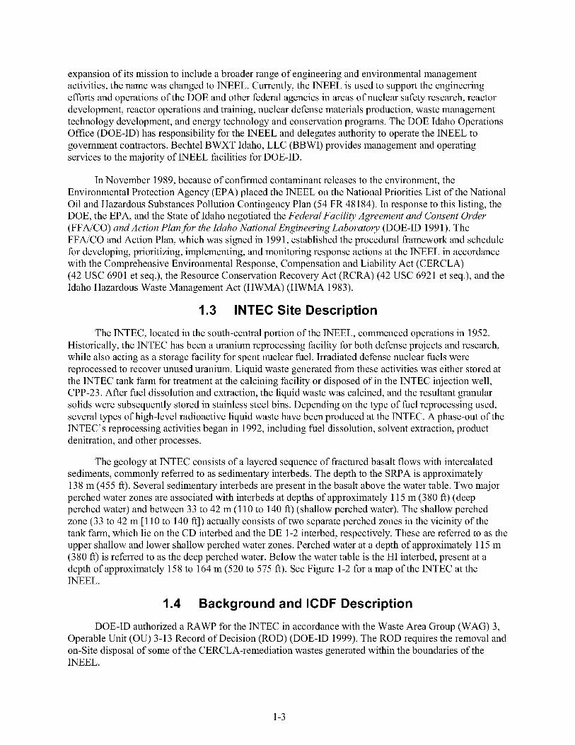
Map of the INTEC at the INEEL (topography adapted from U.S. Geological Survey Circular Butte 3SW. contour interval 10 ft. scale 1:24000) ............................................................ 1-4
WAG 3 area of contamination ......................................................................................................... 1-6
Location of the ICDF Complex components and proximity to the INTEC ..................................... 1-7
ICDF Complex organizational chart ................................................................................................ 9-2
ICDF evacuation routes and assembly area ................................................................................... 10-8
INTEC evacuation routes and assembly areas ............................................................................... 10-9
Map showing the route to the nearest medical facility (CFA-1612) ........................................... 10-10
TABLES
ICDF waste radionuclide inventory ................................................................................................. 2-2
Organic and inorganic waste inventory ........................................................................................... 2-6
Evaluation of chemical agents that may be encountered at the ICDF ........................................... 2-12
Summary of ICDF operational activities. associated hazards. and mitigation .............................. 2.49
Heat stress signs and symptoms of exposure ................................................................................. 2-62
Cold stress work and warmup schedule ........................................................................................ 2-64
Tasks and hazards to be monitored. frequency. and monitoring instrument category .................... 3-2
Monitoring instrument category and description ............................................................................. 3-3
ix

3.3 .
5.1 .
5.2 .
5.3 .
6.1 .
Action levels and associated responses for ICDF operational hazards ........................................... 3.4
Respiratory and protective clothing selection guidance .................................................................. 5.2
Levels and options of personal protective equipment ..................................................................... 5.4
Inspection checklist for personal protection equipment .................................................................. 5-6
ICDF training matrix by position .................................................................................................... 6-3
10.1 . Emergency response equipment to be maintained at the project site during operations ............... 10-3
10.2 . Responsibilities during an emergency .......................................................................................... .1 0.5
10.3 . ICDF emergency contact list ....................................................................................................... 10-12
X
ACGIH
ALARA
ANSI
anti-C
AOC
APF
APR
ASA
BBWI
CAM
CAMU
CERCLA
CFA
CFL
CFR
CPP
DAC
dBA
DOE
DOE-ID
EAM
ECC
EDF
EPA
ER
ACRONYMS
American Conference of Governmental Industrial Hygienists
as low as reasonably achievable
American National Standards Institute
anticontamination
area of contamination
assigned protection factor
air-purifying respirator
auditable safety analysis
Bechtel BWXT Idaho, LLC
continuous air monitor
Corrective Action Management Unit
Comprehensive Environmental, Response, Compensation and Liability Act
Central Facilities Area
central file location
Code of Federal Regulations
Chemical Processing Plant (now the INTEC)
derived air concentration
decibel A-weighted
Department of Energy
Department of Energy Idaho Operations Office
emergency action manager
Emergency Control Center
Engineering Design File
Environmental Protection Agency
environmental restoration
Xi

ERE
ERO
ES&H
ESH&QA
FFAiCO
FR
FTL
GFCI
GI
GM
H&R
HASP
HAS S
HAZWOPER
HEPA
HSO
HVAC
HWMA
ICDF
ICMS
IDLH
IDW
IH
INEEL
INTEC
IRT
Environmental Restoration Information System
Emergency Response Organization
environment, safety, and health
environment, safety, health, and quality assurance
Federal Facility Agreement and Consent Order
Federal Register
field team leader
ground-fault circuit interrupter
gastrointestinal
Geiger-Mueller
hoisting and rigging
Health and Safety Plan
Hazards Assessment and Sampling System
Hazardous Waste Operations and Emergency Response
high-efficiency particulate air
health and safety officer
heating, ventilating, and air conditioning
Hazardous Waste Management Act
INEEL CERCLA Disposal Facility
INEEL Chemical Management System
immediately dangerous to life or health
investigation-derived waste
industrial hygiene, industrial hygienist
Idaho National Engineering and Environmental Laboratory
Idaho Nuclear Technology and Engineering Center
Incident Response Team
x11
ISMS
ISRMS
ITP
JSA
LDR
LEL
LO/TO
MCP
MPS
MSDS
NEPA
NFPA
NIOSH
NRR
OMP
osc OSHA
ou PCB
PCM
PEL
PM
PNOC
PPE
PRD
QA
Integrated Safety Management System
INTEC Services Record Management Supervisor
individual training plan
job safety analysis
land disposal restriction
lower explosive limit
lockout/tagout
management control procedure
Material Profile Sheet
material safety data sheet
National Environmental Policy Act
National Fire Protection Association
National Institute of Occupational Safety and Health
noise reduction rating
Occupational Medical Program
on-scene commander
Occupational Safety and Health Administration
operable unit
polychlorinated biphenyl
personal contamination monitor
permissible exposure limit
project manager
particles not otherwise classified
personal protective equipment
program requirements document
quality assurance
... X l l l

QAPj P
QC
QE
RadCon
RAWP
RBA
RCA
RCIMS
RCRA
RCT
RD/RA
RE
RMD
ROD
RW
RWP
SAD
SAM
SAR
SCBA
SOM
SP
SRPA
S SA
SSSTF
STL
Quality Assurance Project Plan
quality control
quality engineer
Radiological Control
Remedial Action Work Plan
Radiological Buffer Area
Radiologically Controlled Area
Radiological Control and Information Management System
Resource Conservation and Recovery Act
radiological control technician
remedial desigdremedial action
radiological engineer
Records Management Department
Record of Decision
radiological worker
radiological work permit
site area director
Sample and Analysis Management
Safety Analysis Report
self-contained breathing apparatus
shift operational meeting
safety professional
Snake River Plain Aquifer
Staging and Storage Annex
Staging, Storage, Sizing, and Treatment Facility
shift technical lead
xiv
SWB
SWP
TLV
TPR
TSCA
TSD
TSDF
TSR
TWA
USCG
uv VOC
VPP
WAC
WAG
WBGT
WCC
standard waste box
safe work permit
threshold limit value
technical procedure
Toxic Substances Control Act
treatment, storage, and disposal
Treatment, Storage, and Disposal Facility
technical safety requirement
time-weighted average
United States Coast Guard
ultraviolet light
volatile organic compound
Voluntary Protection Program
Waste Acceptance Criteria
waste area group
wet bulb globe temperature
Warning Communications Center
xv

xvi
Health and Safety Plan for INEEL CERCLA Disposal Facility Operations
1. INTRODUCTION
This Health and Safety Plan (HASP) identifies health and safety hazards and requirements used to eliminate and/or minimize the hazards during INEEL CERCLA Disposal Facility (ICDF) operations at the Idaho Nuclear Technology and Engineering Center (INTEC), located at the Idaho National Engineering and Environmental Laboratory (INEEL). This HASP has been written to meet the requirements of the Occupational Safety and Health Administration (OSHA) standard, 29 CFR 1910.120, “Hazardous Waste Operations and Emergency Response” (HAZWOPER). Additional operations will be evaluated by the unreviewed safety questions process, in accordance with applicable company policies and procedures.
1.1 Purpose
This plan has been prepared to address ICDF operational hazards and associated mitigation based on general operations as a Treatment, Storage, and Disposal Facility (TSDF). This HASP and additional job safety analyses (JSAs), operational technical procedures (TPRs), and management control procedures (MCPs) will further define ICDF operational hazards, mitigation, and procedural requirements as the facility begins operations and new hazards are identified. These documents will be maintained at the ICDF Complex as an operational requirement; many of these documents were not submitted for Agency review as part of the Remedial Action Work Plan (RAWP). This HASP will be reviewed and revised, as appropriate, by ICDF industrial hygiene (IH), industrial safety, and radiological operations personnel to ensure its effectiveness and suitability for ICDF operations.
ICDF operations will be conducted under the administrative controls of an auditable safety analysis (ASA). TPRs, JSAs, and other appropriate process health and safety evaluations will be conducted to ensure operations are conducted in compliance with the facility authorization basis. ICDF operations will fall within the site area director’s (SAD’S) jurisdiction. This HASP applies to all personnel conducting ICDF operational activities.
1.2 INEEL Site Description
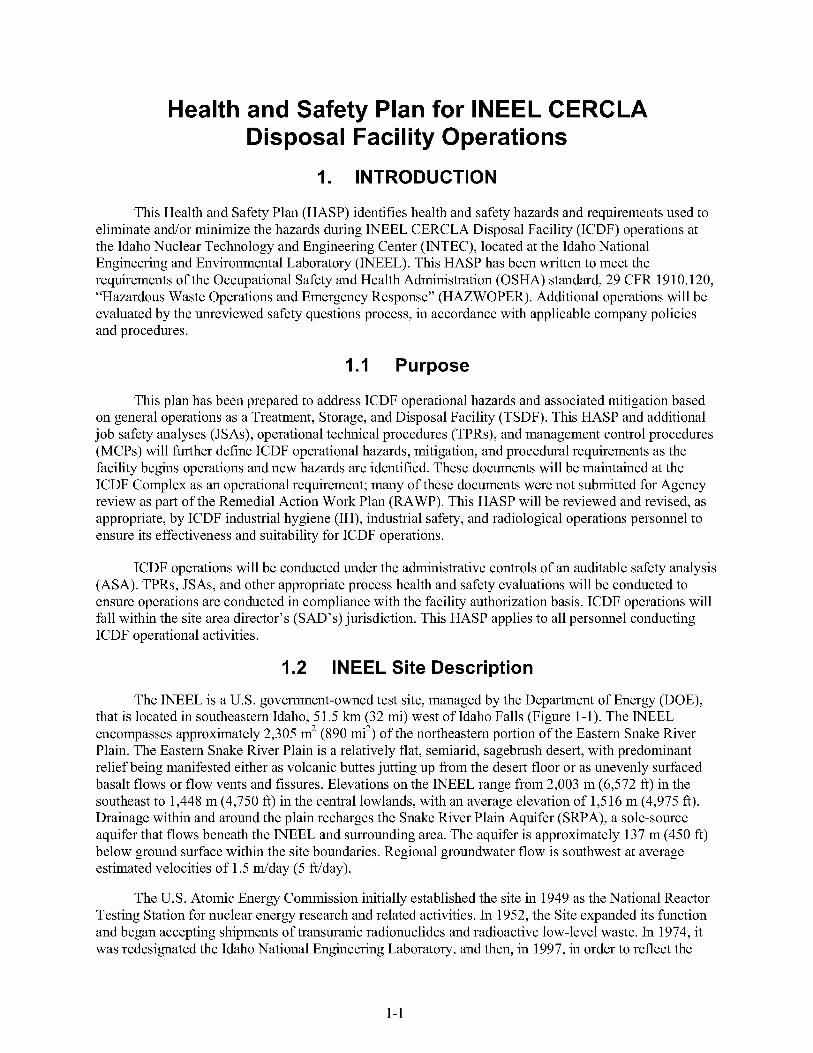
The INEEL is a U.S. government-owned test site, managed by the Department of Energy (DOE), that is located in southeastern Idaho, 51.5 km (32 mi) west of Idaho Falls (Figure 1-1). The INEEL encompasses approximately 2,305 m’ (890 mi’) of the northeastern portion of the Eastern Snake River Plain. The Eastern Snake River Plain is a relatively flat, semiarid, sagebrush desert, with predominant relief being manifested either as volcanic buttes jutting up from the desert floor or as unevenly surfaced basalt flows or flow vents and fissures. Elevations on the INEEL range from 2,003 m (6,572 ft) in the southeast to 1,448 m (4,750 ft) in the central lowlands, with an average elevation of 1,5 16 m (4,975 ft). Drainage within and around the plain recharges the Snake River Plain Aquifer (SRPA), a sole-source aquifer that flows beneath the INEEL and surrounding area. The aquifer is approximately 137 m (450 ft) below ground surface within the site boundaries. Regional groundwater flow is southwest at average estimated velocities of 1.5 &day ( 5 ft/day).
The U.S. Atomic Energy Commission initially established the site in 1949 as the National Reactor Testing Station for nuclear energy research and related activities. In 1952, the Site expanded its function and began accepting shipments of transuranic radionuclides and radioactive low-level waste. In 1974, it was redesignated the Idaho National Engineering Laboratory, and then, in 1997, in order to reflect the
1-1

0 5 10 15 20 Miles
0 5 10 15 20 25 30 35 K M
Figure 1-1. Map of the Idaho National Engineering and Environmental Laboratory.
1 -2
expansion of its mission to include a broader range of engineering and environmental management activities, the name was changed to INEEL. Currently, the INEEL is used to support the engineering efforts and operations of the DOE and other federal agencies in areas of nuclear safety research, reactor development, reactor operations and training, nuclear defense materials production, waste management technology development, and energy technology and conservation programs. The DOE Idaho Operations Office (DOE-ID) has responsibility for the INEEL and delegates authority to operate the INEEL to government contractors. Bechtel BWXT Idaho, LLC (BBWI) provides management and operating services to the majority of INEEL facilities for DOE-ID.
In November 1989, because of confirmed contaminant releases to the environment, the Environmental Protection Agency (EPA) placed the INEEL on the National Priorities List of the National Oil and Hazardous Substances Pollution Contingency Plan (54 FR 48184). In response to this listing, the DOE, the EPA, and the State of Idaho negotiated the Federal Facility Agreement and Consent Order (FFNCO) and Action Plan for the Idaho National Engineering Laboratory (DOE-ID 1991). The FFNCO and Action Plan, which was signed in 1991, established the procedural framework and schedule for developing, prioritizing, implementing, and monitoring response actions at the INEEL in accordance with the Comprehensive Environmental Response, Compensation and Liability Act (CERCLA) (42 USC 6901 et seq.), the Resource Conservation Recovery Act (RCRA) (42 USC 6921 et seq.), and the Idaho Hazardous Waste Management Act (HWMA) (HWMA 1983).
1.3 INTEC Site Description
The INTEC, located in the south-central portion of the INEEL, commenced operations in 1952. Historically, the INTEC has been a uranium reprocessing facility for both defense projects and research, while also acting as a storage facility for spent nuclear fuel. Irradiated defense nuclear fuels were reprocessed to recover unused uranium. Liquid waste generated from these activities was either stored at the INTEC tank farm for treatment at the calcining facility or disposed of in the INTEC injection well, CPP-23. After fuel dissolution and extraction, the liquid waste was calcined, and the resultant granular solids were subsequently stored in stainless steel bins. Depending on the type of fuel reprocessing used, several types of high-level radioactive liquid waste have been produced at the INTEC. A phase-out of the INTEC’s reprocessing activities began in 1992, including fuel dissolution, solvent extraction, product denitration, and other processes.
The geology at INTEC consists of a layered sequence of fractured basalt flows with intercalated sediments, commonly referred to as sedimentary interbeds. The depth to the SRPA is approximately 138 m (455 ft). Several sedimentary interbeds are present in the basalt above the water table. Two major perched water zones are associated with interbeds at depths of approximately 115 m (380 ft) (deep perched water) and between 33 to 42 m (1 10 to 140 ft) (shallow perched water). The shallow perched zone (33 to 42 m [ 110 to 140 ft]) actually consists of two separate perched zones in the vicinity of the tank farm, which lie on the CD interbed and the DE 1-2 interbed, respectively. These are referred to as the upper shallow and lower shallow perched water zones. Perched water at a depth of approximately 1 15 m (380 ft) is referred to as the deep perched water. Below the water table is the HI interbed, present at a depth of approximately 158 to 164 m (520 to 575 ft). See Figure 1-2 for a map of the INTEC at the INEEL.
1.4 Background and ICDF Description
DOE-ID authorized a RAWP for the INTEC in accordance with the Waste Area Group (WAG) 3, Operable Unit (OU) 3-13 Record of Decision (ROD) (DOE-ID 1999). The ROD requires the removal and on-Site disposal of some of the CERCLA-remediation wastes generated within the boundaries of the INEEL.
1-3
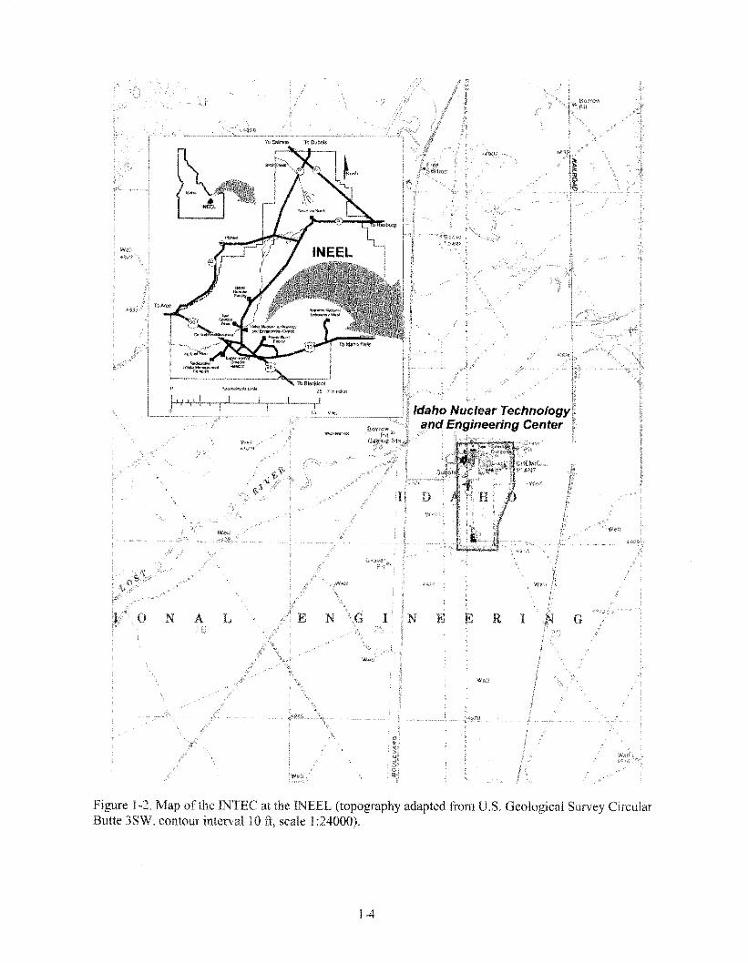

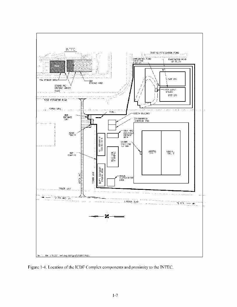
The ROD requirements necessitate the construction of the ICDF, which will be the disposal facility for the ROD-identified waste streams. The ICDF is an on-Site, engineered facility, located south of INTEC and adjacent to the existing percolation ponds, that meets the substantive requirements of RCRA Subtitle C (42 USC 6921 et seq.), Idaho HWMA (HWMA 1983), DOE Order 435.1, and Toxic Substances Control Act (TSCA) polychlorinated biphenyl (PCB) landfill design and construction requirements (1 5 USC 2601 et seq.). Designed and authorized to accept not only WAG 3 wastes, but also wastes from other INEEL CERCLA actions, the ICDF Complex will include the necessary subsystems and support facilities to provide a complete waste disposal system.
The major components of the ICDF include
0 The disposal cells (landfill)
0 Two evaporation pond cells
The Staging, Storage, Sizing, and Treatment Facility (SSSTF).
The ICDF Complex, including the SSSTF and a buffer zone, covers approximately 50 acres, with a disposal capacity of approximately 5 10,000 yd3. The evaporation pond, designated as equivalent to a RCRA Corrective Action Management Unit (CAMU) in the OU 3-13 ROD, will be the disposal site for ICDF leachate and other aqueous wastes generated as a result of operating the ICDF Complex. It will also accept decontamination water and water from CERCLA-generated well purging, sampling, and well development activities. The ICDF leachate will be pumped directly to the evaporation pond, and the pump system will track the volume of waste disposed to the pond.
The SSSTF will be designed to provide the centralized receiving, inspection, treatment, and segregation areas necessary to stage and store incoming waste from the other INEEL CERCLA remediation sites prior to disposal to the ICDF landfill or shipment off-Site. All SSSTF activities shall take place within the WAG 3 area of contamination (AOC) to allow flexibility in managing the consolidation and remediation of wastes without triggering land disposal restrictions (LDRs) and other RCRA requirements, in accordance with the OU 3-13 ROD, although LDRs will apply to waste generated outside the WAG 3 AOC or to those wastes that have triggered placement. Figure 1-3 illustrates the WAG 3 AOC. Figure 1-4 illustrates the areas of the ICDF Complex.
A short-term storage/staging area, the Staging and Storage Annex (SSA), is already located within the INTEC fenced area to serve as a temporary storage or staging area for INEEL CERCLA waste designated for
0 Direct disposal to the ICDF landfill
0 Packaging in preparation for off-Site disposal
0 Other INEEL on-Site disposal.
Wastes from WAG 3 and other CERCLA remediation sites will be stored at the SSA during the design and construction phases of the ICDF Complex, including the construction of the SSSTF. When the SSSTF becomes operational, the SSA will administratively become part of the SSSTF, which, in turn, will be a fundamental element of the ICDF Complex. The SSA waste acceptance must meet the Waste Acceptance Criteria (WAC) before it will be managed at the SSA.
1-5

TRA
FA
Experimental - Field Stat ion v -
L INTEC
0 .25 .50
Scale in miles
0 5 1 - Scale in kilometers
AC3662 9-98
Figure 1-3. WAG 3 area of contamination.
1-6
3NTAMINATED IUIPMENT PAD
LANDFILL CELL 1
-E-
WNU FI LL CELL 3
l R c v 1. file plUd001Lrevl.dwg bbh\proi\162870lNEEL
Figure 1-4. Location of the ICDF Complex components and proximity to the WTEC.
1-7
The evaporation pond, designated as equivalent to a CAMU in accordance with the substantive requirements of IDAPA 58.01.05.008 (40 CFR 264.552 and 40 CFR 264 Subparts K and CC), will accept and provide treatment/disposal capability for ICDF leachate; aqueous wastes generated as a result of operating the ICDF Complex (DOE-ID 1999); potentially contaminated aqueous waste streams generated from the INTEC and other INEEL CERCLA actions; and decontamination water and water from CERCLA-generated well purging, sampling, and well development activities. The ICDF leachate will be pumped directly to the evaporation pond, and the pump system will track the volume of waste disposed to the pond.
The SSSTF is the center for all waste handling and processing for the ICDF Complex. It is designed to provide centralized receiving, inspection, treatment, and segregation areas necessary to stage, store, and size incoming waste from various INEEL CERCLA remediation sites prior to ICDF disposal or shipment off-Site. Wastes meeting the ICDF WAC will be transported to the ICDF. Wastes that do not meet the ICDF WAC will be treated to meet the ICDF WAC, packaged for shipment off-Site, or transported to appropriate on-Site disposal. All SSSTF activities shall take place within the WAG 3 AOC to allow flexibility in managing the consolidation and remediation of wastes without triggering LDRs and other RCRA requirements, in accordance with the OU 3-13 ROD. However, LDRs will apply to waste generated outside the WAG 3 AOC or to those wastes that have triggered placement.
Currently, approximately 413,000 yd3 (3 15,700 m3) of INEEL CERCLA remediation waste, about 80% of the authorized capacity, have been identified for disposal in the ICDF during the first 10 years of operation. In addition to remediation waste, an additional 78 yd3 (60 m3) of IDW will be generated as part of the OU 3-14 tank farm investigation and disposed in the ICDF.
1.5 ICDF Components and Operations
Operational aspects of the ICDF Complex are described in the following sections. Each activity associated with ICDF operations will incorporate hazard identification and mitigation measures and follow applicable company policies and procedures.
1.5.1 Initial Waste Arrival at ICDF
Waste will arrive at the ICDF Complex from various on-Site INEEL CERCLA remediation sites. These sites and waste forms are grouped into the following categories: (1) landfill waste (waste meeting the ICDF landfill WAC without treatment), (2) stabilization waste (nonaqueous waste requiring stabilization in the SSSTF), (3) well development/purge water (aqueous waste from well purging and development activities), and (4) case-by-case waste (essentially waste that will require special handling procedures).
The access to the ICDF will initially be by an all-weather road with a maximum 10% grade, located on the southern, unlined portion of the excavation. This access road is wide enough to carry two-way traffic.
1.5.2 Waste Receipt
The waste receiving process includes the steps taken from the arrival of the waste at the SSSTF to disposal at the ICDF landfill or evaporation pond or to the staging of the waste prior to its transfer off-Site.
A Material Profile Sheet (MPS) for each waste container will have been approved by SSSTFDCDF administrative personnel before arrival of the waste at the ICDF Complex gate. All required
1-8
fingerprinting of the waste will have been performed prior to shipment by the INEEL site generating the waste. Waste sent to the ICDF Complex must meet the appropriate components of the ICDF WAC (which includes the ICDF landfill WAC, the ICDF Complex WAC, and the ICDF evaporation pond WAC) to be accepted for processing in the ICDF Complex.
Validation of the waste shipment will include an initial inspection of the waste to determine whether it matches the identity of the waste specified on the MPS. This inspection will verify information such as an adequate MPS, actual number and type of containers matching the MPS, and intact containers. All waste loads will be validated (load inspection and quality assurance [QA] verification of load profile) to comply with QA guidelines and regulations, and pertinent information will be entered into the ICDF waste tracking system. Waste acceptance and receipt of soils destined for disposal in the ICDF landfill will also be dependent on the results of verification samples collected from the containerized waste to verify the waste matches the characteristics identified on the MPS. Verification sampling will be overseen by ICDF Complex personnel prior to acceptance of the waste at the ICDF Complex.
1.5.3 Weighing and Tracking
Waste entering or exiting the ICDF will be weighed and included in the waste tracking system at the weigh scale station. The weighing process shall have the capability to determine the weight of the waste vehicle being processed to comply with landfill standards for cell location and cell content. Additional tracking of the waste will be required during various treatment and staging/storage activities. On a case-by-case basis, some wastes will require additional tracking.
The weighing scale will be designed to accommodate a single truck containing either bulk waste or loaded with 1 3-yd3, waste-laden, roll-off containers. Once the shipments have been weighed, pertinent information will be entered into an ICDF tracking system.
1 S.4 Waste Storage and Staging
After receiving the incoming waste shipments, the transport vehicles may deliver the loads directly to the ICDF landfill. Storage and staging areas are provided for a small number of containers of each waste type and bulk soil to allow for delays in processing and to stage waste for treatment.
1 S.5 Waste Treatment
The decon building provides treatment capabilities to treat INEEL CERCLA wastes and secondary waste streams generated during ICDF Complex operations, if needed. The purpose of treatment via stabilization is to prepare INEEL CERCLA waste that does not meet the ICDF landfill WAC for final disposal in the ICDF landfill or at an off-Site disposal facility. The object of stabilization is produce a treated waste that will (1) reduce the contaminant leachability to meet the ICDF landfill WAC and (2) exhibit no free liquid. The main components of the stabilization process are the vertical lift tipper, a mixer unit, a bulk-bag unloader, roll-odroll-off container for collecting the treated waste from the mixer, and an air filtration system to collect particulates from the air.
Treatment of hazardous debris also will be performed at the decon building using Portland cement-based microencapsulation for debris wastes that require treatment prior to disposal. Microencapsulation encases the hazardous debris in inorganic materials (Portland cement concrete) to substantially reduce the surface exposure to potential leaching media. The components to the debris treatment process are the grout hopper/reservoir, positive displacement pump, hose, and box brace. Debris treatment equipment is portable and will be used in either the treatment area or decon bay of the decon building.
1-9

1 S.6 Disposal
Landfill wastes and treated stabilization wastes planned for disposal in the ICDF have unique characteristics for unloading, placement, and compaction. Waste material placement activities shall be conducted in a manner that protects and maintains the integrity of the liner system, leachate collection system, final cover system, and all ICDF Complex ancillary facilities and equipment.
The majority of the material sent for disposal in the ICDF will be bulk soils. These waste soils will be transported to the site in self-dumping vehicles. The placement of this material is expected to be accomplished by standard construction methods for unloading, spreading, grading, and compaction of soils unless already containerized. The trucks will be off-loaded under the direction of a field supervisor. Containerized waste may be placed within the landfill using other methods. Moisture treatment of the soil may be required to achieve adequate compaction. ICDF health, safety, and radiological support personnel will evaluate hazards from these operations and determine the appropriate controls.
Containers, including wooden and steel boxes and drums, will also be sent for disposal at the ICDF. The boxes may contain soil, stabilized soil material, scrap metal, and building debris. The boxes will be unloaded with specialized equipment. The containers will be placed so that the equipment used to spread the material can crush the boxes, which will allow their contents to be evenly spread and allow thorough compaction of the material.
Building demolition material will be sent to the ICDF. This material will be unloaded using specialized equipment, appropriate and consistent with operation procedures, and will be placed so that excessive localized void space will not be created.
The filling sequence will begin with 10-ft-thick layers built up in three layers to reach the crest of the excavation. The initial layer will consist of a 5-ft-thick select fill layer placed on top of the operation layer and then another 5-ft layer of general waste constructed over the initial layer. The next two 10-ft-thick layers will consist of general waste. Each of the 10-ft-thick layers will be constructed so that all the waste material is compacted into 1 -ft-thick lifts. Each lift is placed, graded, and compacted until reaching the 10-ft-thick layer requirement. Actual fill sequence may vary based on volume and type of incoming fill.
Following removal of the waste material from the transport vehicle/container, the roll-off container or truck will be surveyed for external radiological contamination. Any truck that requires decontamination will decontaminated by first using dry techniques, with wet decontamination techniques used second to minimize generation of aqueous waste. Empty waste transfer vehicles or roll-off containers released by radiological control personnel will then return to the scales to be weighed and will leave the SSSTF through the gate.
1 S.7 Container Storage and Staging
After decontamination, the empty containers will be delivered to a staging pad for empty roll-off containers until they are required for further use. Empty drums and/or standard waste boxes (SWBs) will be sized or reused, as appropriate. Waste minimization applications will be implemented during this process.
1.5.8 Leachate Conveyance System
A leachate conveyance system has been incorporated into the design of the ICDF. This system transfers leachate from the landfill sumps to the evaporation pond. The operational activities associated with this system include
1-10
0 Flow measurement
0 Leak detection
0 Instrument and equipment calibration
0 Normal and emergency shutdown sequences
0 Preventative maintenance
0 Inspection
0 Sampling and analysis
0 Cleaning/sediment removal.
1 S.9 Evaporation Pond
The evaporation pond consists of two cells that accept aqueous wastes such as landfill leachate and other liquid waste sources from WAG 3 or from ICDF Complex operations. The water associated with the wastes will evaporate, leaving behind the solid materials. Routine tasks associated with management of the ICDF evaporation pond include pond cell washdown and transfer of aqueous waste to the evaporation pond. Additional nonroutine tasks are described in the ICDF Complex Operations and Maintenance Plan (DOE-ID 2003).
1.5.10 Additional ICDF Tasks
Additional tasks associated with ICDF operations include preventative maintenance, inspections, road maintenance, fencing inspection and repair, stormwater ditchederosion control inspection, repair and maintenance, evaporation pond sampling, LCRS sampling, other routine sampling tasks, and groundwater monitoring. All ICDF operational activities will be evaluated to identify safety and health hazards and to determine the appropriate mitigation and control measures.
1.6 Program Interfaces
The interface agreement between the Environmental Restoration (ER) Program and the INTEC (IAG-89) describes the working relationships for activities and programs conducted by ER at the INTEC. The ER programs at INTEC are being conducted under the regulatory authority of the CERCLA (42 USC 6901 et seq.); the ROD for INTEC, WAG 3, OU 3-13 (DOE-ID 1999); and FFNCO (DOE-ID 1991).
The ICDF operates as a facility under the purview of the SAD and is an INTEC facility. ICDF operations will be conducted in accordance with the ICDF ASA, this HASP, IAG-89, and ICDF operating procedures (standard and detailed).
1-1 1
2. HAZARD IDENTIFICATION AND MITIGATION
ICDF operations will involve the transportation, handling, storage, treatment, and disposal of approximately 413,000 yd3 (315,700 m3) of INEEL CERCLA waste and an additional 78 yd3 (60 m3) of IDW generated as part of the OU 3-14 tank farm investigation. This waste includes low-level, mixed low-level, hazardous, and limited quantities of TSCA-regulated waste. Operation of the ICDF will present physical, chemical, and radiological hazards to operations personnel, so identification and mitigation of these hazards is imperative to prevent injury or exposure to personnel conducting these activities. The primary objective of this section is to identify existing and anticipated hazards based on ICDF operations and to provide controls to eliminate or mitigate these hazards. This includes
0 Evaluation of ICDF operations to determine the extent that potential industrial safety, radiological, nonradiological, and physical hazards may affect facility personnel
0 Establishment of the necessary monitoring and sampling required to evaluate exposure and contamination levels, determine action levels to prevent exposures, and provide specific actions to be followed if action levels are reached
0 Determination of necessary engineering controls, isolation methods, administrative controls, work practices, and (where these measures will not adequately control hazards) personal protective equipment (PPE) to further protect project personnel from hazards.
The purpose of this hazard identification section is to lead the user to an understanding of the occupational safety and health hazards associated with ICDF operational tasks. This will enable project management and safety and health professionals to make effective and efficient decisions related to the equipment, processes, procedures, and the allocation of resources to protect the safety and health of project personnel.
The magnitude of danger presented by these hazards to personnel entering work zones is dependent on both the nature of tasks being performed and the proximity of personnel to the hazards. Engineering controls will be implemented (whenever possible) along with administrative controls, work practices, and PPE to further mitigate potential exposures and hazards. This following section describes the chemical, radiological, safety, and environmental hazards that personnel may encounter while conducting ICDF operational activities. Hazard mitigation provided in this section in combination with other work controls (e.g., technical procedures, work orders, JSA, and applicable company policies and procedures also will be used where applicable to eliminate or mitigate project hazards.
2.1 Chemical and Radiological Hazards and Mitigation
Personnel may be exposed to industrial safety hazards or to radiological, nonradiological, and physical agents while conducting ICDF operations. Engineering controls will be implemented (whenever possible), along with adequate work practice controls (administrative), real-time monitoring of personnel exposure to contaminants, and ICDF facility-specific hazard training to further mitigate potential hazards and exposures. Formal preplanning (job walk-down, completion of the hazard profile screening checklist, and prejob briefing checklist), written procedures, JSAs, and other work controls will be written based on the hazards identified in this HASP, technical procedures, applicable company policies and procedures work packages, and facility-specific conditions. These documents will specify operational hazard mitigation measures to follow.
The ICDF Short Term Risk Assessment (EDF-ER-327) identifies three chemicals which exceed the hazard index for noncancer effects to the evaporation pond operator. The hazard index for noncancer
2-1

effects for the evaporation pond operator is 4; the primary contributors to noncancer risk are 2-nitroaniline, 3-nitroaniline, and 4-nitroaniline. These materials will remain in solution due to their solubility. Evaporated liquids will tend to leave precipitous materials (contaminated) behind the nitroanaline compounds. To avoid personnel exposure to these compounds, personnel will be restricted from skin contact which is the primary exposure route of these compounds. Pond cleaning and handling procedures will specifically address the potential hazards and mitigations during pond sediment handling operations. Initial and periodic sampling may be instituted by the facility IH to ensure the effectiveness of instituted control measures.
Several tables are presented in this section that identify the potential hazards that may be encountered during ICDF operations based on known waste inventory, monitoring methods, and other hazard-specific mitigation measures. These include
Table 2-1, ICDF waste radionuclide inventory
Table 2-2, ICDF organic and inorganic waste inventory
Table 2-3, Evaluation of chemical agents that may be encountered at the ICDF
Table 2-4, Summary of ICDF operational activities, associated hazards, and mitigation
Table 2-5, ICDF operations - radiological and nonradiological hazards to be monitored
Table 2-6, Typical equipment available for monitoring radiological and nonradiological hazards
Table 2-7, Exposure limits for select ICDF operational hazards and corresponding response.
Table 2-1. ICDF waste radionuclide inventorya'b.
Contaminated Activity Contaminated Activity Soil Volume (Ci) Volume Soil (Ci)
Radionuclide Half-life (m3)' (1/1/2002) Radionuclide Half-life (m3)' (1/1/2002)
H-3
Be-10
C-14
K-40
SC-46
Cr-5 1
Mn-54
Co-57
CO-58
Fe-59
Co-60
Zn-65
Se-79
Kr-8 1
Kr-85
Rb-86
1.23E+01
1.60E+06
5.73E+03
1.28E+09
2.30E-01
7.39E-02
8.56E-01
7.42E-01
1.94E-0 1
1.22E-01
5.27E+00
6.69E-0 1
6.50E+04
2.10E+05
1.07E+01
5.1 1E-02
3 12,598
3 12,598
3 12,598
3 12,598
3 12,598
3 12,598
3 12,598
3 12,598
3 12,598
3 12,598
3 12,598
312,598
3 12,598
3 12,598
3 12,598
3 12,598
2.3E+01
5.4E-07
2.2E-05
9.1E-01
1.3E-20
1.1E-54
9.1E-09
1.7E-03
2.8E-17
2.1E-35
9.2E+01
1.3E-09
7.9E-02
2.5E-09
5.5E+02
O.OE+OO
Rh-106
Ag-106
Pd-107
Ag-108
Ag-1OSm
Ag-109m
Cd-109
Ag-110
Ag-l10m
Ag-111
Cd-113m
In-1 14
In-1 14m
Cd-115m
In-115
In-115m
9.51E-07
4.56E-05
6.50E+06
4.51E-06
1.27E+02
1.25E-06
1.27E+00
7.79E-07
6.84E-0 1
2.04E-02
1.37E+O 1
2.28E-06
1.36E-0 1
1.22E-01
4.60E+15
5.12E-04
3 12,598
3 12,598
3 12,598
3 12,598
3 12,598
3 12,598
3 12,598
3 12,598
3 12,598
3 12,598
3 12,598
3 12,598
3 12,598
3 12,598
3 12,598
3 12,598
5.4E-03
O.OE+OO
2.9E-03
1.8E-09
3.8E-01
2.3E-12
2.3E-12
2.5E-11
2.6E-09
O.OE+OO
7.7E-01
8.9E-55
9.4E-55
2.0E-54
2.7E- 12
O.OE+OO
2 -2
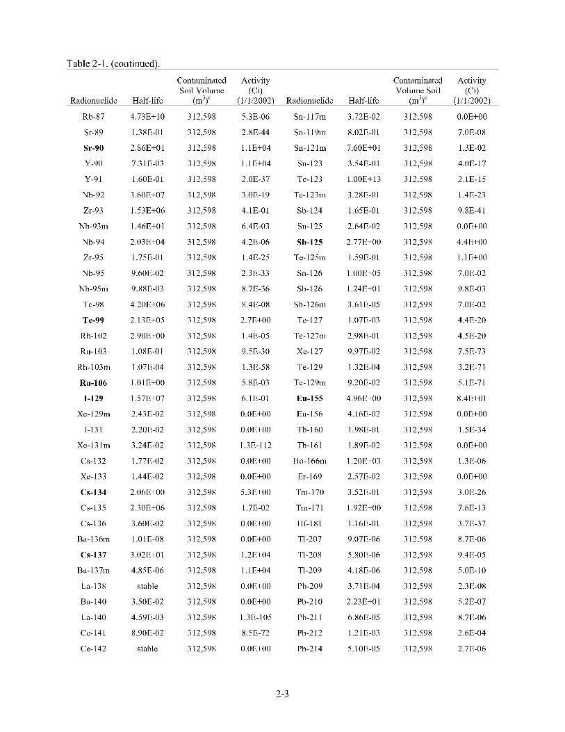
Table 2-1. (continued).
Contaminated Activity Contaminated Activity Soil Volume (Ci) Volume Soil (Ci)
Radionuclide Half-life (m3)' (1/1/2002) Radionuclide Half-life (m3)' (1/1/2002)
Rb-87
Sr-89
Sr-90
Y-90
Y-91
Nb-92
Zr-93
Nb-93m
Nb-94
Zr-95
Nb-95
Nb-95m
Tc-98
Tc-99
Rh-102
Ru-103
Rh-103m
Ru-106
1-129
Xe-129m
1-131
Xe-131m
CS-132
Xe-133
CS-134
CS-135
CS-136
Ba-136m
CS-137
Ba-137m
La-138
Ba-140
La- 140
Ce-141
Ce-142
4.73E+ 10
1.3 8E-0 1
2.8 6E+O 1
7.3 1E-03
1.60E-0 1
3.60E+07
1.53E+06
1.46E+01
2.03E+04
1.75E-0 1
9.60E-02
9.88E-03
4.20E+06
2.13E+05
2.90E+00
1.08E-01
1.07E-04
l.OlE+OO
1.57E+07
2.43E-02
2.20E-02
3.24E-02
1.77E-02
1.44E-02
2.06E+00
2.3 OE+06
3.60E-02
1.01E-08
3.02E+O 1
4.85E-06
stable
3.50E-02
4.59E-03
8.90E-02
stable
3 12,598
3 12,598
3 12,598
3 12,598
312,598
3 12,598
3 12,598
3 12,598
3 12,598
3 12,598
3 12,598
3 12,598
3 12,598
3 12,598
3 12,598
3 12,598
3 12,598
3 12,598
3 12,598
3 12,598
3 12,598
3 12,598
3 12,598
3 12,598
3 12,598
3 12,598
3 12,598
3 12,598
3 12,598
3 12,598
3 12,598
3 12,598
3 12,598
3 12,598
3 12,598
5.3E-06
2.8E-44
l.lE+04
l.lE+04
2.0E-37
3 .OE- 19
4.1E-01
6.4E-03
4.2E-06
1.4E-25
2.3E-33
8.7E-36
8.4E-08
2.7E+00
1.4E-05
9.5E-30
1.3E-58
5.8E-03
6.1E-01
O.OE+OO
O.OE+OO
1.3E-112
O.OE+OO
O.OE+OO
5.3E+00
1.7E-02
O.OE+OO
O.OE+OO
1.2E+04
l.lE+04
O.OE+OO
O.OE+OO
1.3E-105
8.5E-72
O.OE+OO
Sn- 1 17m
Sn- 1 19m
Sn- 12 l m
Sn-123
Te-123
Te-123m
Sb-124
Sn- 125
Sb-125
Te-125m
Sn-126
Sb-126
Sb-126m
Te-127
Te-127m
Xe-127
Te-129
Te-129m
Eu-155
Eu-156
Tb- 160
Tb-161
Ho- 166m
Er- 169
Tm- 170
Tm-171
Hf-181
TI-207
TI-208
TI-209
Pb-209
Pb-210
Pb-2 1 1
Pb-212
Pb-214
3.72E-02
8.02E-0 1
7.60E+O 1
3.54E-01
1.00E+13
3.28E-01
1.65E-01
2.64E-02
2.77E+00
1.59E-01
1.00E+05
1.24E+O 1
3.6 1E-05
1.07E-03
2.98E-01
9.97E-02
1.32E-04
9.20E-02
4.96E+00
4.16E-02
1.98E-01
1.89E-02
1.20E+03
2.57E-02
3.52E-01
1.92E+00
1.16E-01
9.07E-06
5.80E-06
4.18E-06
3.7 1E-04
2.23E+0 1
6.86E-05
1.21E-03
5.1 OE-05
3 12,598
3 12,598
3 12,598
3 12,598
3 12,598
3 12,598
3 12,598
3 12,598
3 12,598
3 12,598
3 12,598
3 12,598
3 12,598
3 12,598
3 12,598
3 12,598
3 12,598
3 12,598
3 12,598
3 12,598
3 12,598
3 12,598
3 12,598
3 12,598
3 12,598
3 12,598
3 12,598
3 12,598
3 12,598
3 12,598
3 12,598
3 12,598
3 12,598
3 12,598
3 12,598
O.OE+OO
7.OE-08
1.3E-02
4.OE-17
2.1E-15
1.4E-23
9.8E-41
O.OE+OO
4.4E+00
l.lE+OO
7.OE-02
9.8E-03
7.OE-02
4.4E-20
4.5E-20
7.5E-73
3.2E-7 1
5.1E-71
8.4E+01
O.OE+OO
1.5E-34
O.OE+OO
1.3E-06
O.OE+OO
3.0E-26
7.6E- 13
3.7E-37
8.7E-06
9.4E-05
5.OE- 10
2.3E-08
5.2E-07
8.7E-06
2.6E-04
2.7E-06
2-3

Table 2-1. (continued).
Contaminated Activity Contaminated Activity Soil Volume (Ci) Volume Soil (Ci)
Radionuclide Half-life (m3)' (1/1/2002) Radionuclide Half-life (m3)' (1/1/2002)
Pr-143
Ce-144
Pr- 144
Pr- 144m
Nd- 144
Pm-146
Sm-146
Nd-147
Pm-147
Sm-147
Pm-148
Pm-148m
Sm-148
Sm-149
Eu- 150
Sm-151
Eu-152
Gd- 152
Gd-153
Eu-154
Ra-222
Ra-223
Ra-224
Ra-225
Ra-226
Ra-228
Ac-225
Ac-227
Ac-228
Th-226
Th-227
Th-228
Th-229
Th-230
Th-23 1
3.71E-02
7.78E-01
3.29E-05
1.3 7E-05
5.00E+15
5.53E+00
7.00E+07
3.01E-02
2.62E+00
1.06E+11
1.47E-02
1.13E-01
1.20E+13
4.00E+ 14
5.00E+00
9.00E+01
1.36E+O 1
l.lOE+14
6.6 1E-0 1
8.80E+00
1.20E-06
3.13E-02
9.9 1E-03
4.05E-02
1.60E+03
5.75E+00
2.74E-02
2.18E+O 1
6.99E-04
5.87E-05
5.13E-02
1.9 1E+00
7.34E+03
7.70E+04
2.9 1E-03
3 12,598
3 12,598
3 12,598
3 12,598
312,598
3 12,598
3 12,598
3 12,598
312,598
3 12,598
3 12,598
3 12,598
3 12,598
3 12,598
3 12,598
312,598
3 12,598
312,598
3 12,598
3 12,598
3 12,598
3 12,598
3 12,598
3 12,598
3 12,598
3 12,598
3 12,598
3 12,598
3 12,598
3 12,598
3 12,598
3 12,598
3 12,598
3 12,598
3 12,598
O.OE+OO
8.6E-04
8.4E-04
1.2E-05
1.5E-10
2.8E-03
2.OE-10
O.OE+OO
1.8E+02
1.9E-06
1.9E-59
3.9E-58
4.8E-13
2.4E-12
8.2E-09
1.6E+02
4.6E+02
1.3E-14
9.5E-12
3.9E+02
5.5E-117
9.6E-06
2.6E-04
2.4E-08
2.2E-01
7.2E-11
2.4E-08
9.7E-06
7.2E-11
1.OE-117
8.6E-06
1.6E-02
2.4E-08
8.2E-02
7.6E-02
Bi-210
Bi-2 1 1
Bi-212
Bi-2 13
Bi-214
Po-210
Po-2 1 1
Po-212
PO-2 13
PO-214
PO-2 15
PO-2 16
PO-2 18
At-2 17
Rn-2 18
Rn-2 19
Rn-220
Rn-222
Fr-22 1
Fr-223
Np-239
Np-240
Np-240m
Pu-236
Pu-237
Pu-238
Pu-239
Pu-240
Pu-24 1
Pu-242
Pu-243
Pu-244
Pu-246
Am-241
Am-242m
1.37E-02
4.05E-06
1.15E-04
8.68E-05
3.78E-05
3.79E-01
1.64E-08
9.44E-15
1.33E-13
5.20E- 12
6.34E-11
4.63E-09
5.80E-06
1.01E-09
1.1 1E-09
1.25E-07
1.76E-06
1.05E-02
9.13E-06
4.14E-05
6.45E-03
1.24E-04
1.41E-05
2.8 5E+00
1.24E-0 1
8.78E+O 1
2.4 1E+04
6.5 7E+03
1.44E+O 1
3.76E+05
5.65E-04
8.26E+07
2.97E-02
4.3 2E+02
1.52E+02
3 12,598
3 12,598
3 12,598
3 12,598
3 12,598
3 12,598
3 12,598
3 12,598
3 12,598
3 12,598
3 12,598
3 12,598
3 12,598
3 12,598
3 12,598
3 12,598
3 12,598
3 12,598
3 12,598
3 12,598
3 12,598
3 12,598
3 12,598
3 12,598
3 12,598
3 12,598
3 12,598
3 12,598
3 12,598
3 12,598
3 12,598
3 12,598
3 12,598
3 12,598
3 12,598
5.2E-07
8.7E-06
2.6E-04
O.OE+OO
2.7E-06
4.8E-07
3.2E-10
1.6E-04
2.1E-08
2.7E-06
8.7E-06
2.6E-04
2.7E-06
2.4E-08
6.OE-117
9.6E-06
2.6E-04
2.9E-06
2.4E-08
1.3E-07
1.6E-04
1.3E-14
1.2E- 1 1
2.6E-06
5.7E-59
l.lE+02
3.2E+00
7.1E-01
3 .OE+O 1
1.1E-04
3 .OE- 16
1.2E- 1 1
6.5E-26
l.lE+Ol
2.1E-05
2 -4

Table 2-1. (continued).
Contaminated Activity Contaminated Activity Soil Volume (Ci) Volume Soil (Ci)
Radionuclide Half-life (m3)‘ (1/1/2002) Radionuclide Half-life (m3)‘ (1/1/2002)
Th-232
Th-234
Pa-23 1
Pa-233
Pa-234m
Pa-234
U-230
U-232
U-233
U-234
U-235
U-236
U-237
U-238
U-240
Np-235
Np-236
Np-237
1.40E+ 10
6.60E-02
3.73E+04
7.39E-02
2.22E-06
7.64E-04
5.69E-02
7.20E+01
1.59E+05
2.44E+05
7.04E+08
2.3 4E+07
1.85E-02
4.47E+09
1.61E-03
1.08E+00
1.15E+05
2.14E+06
3 12,598
3 12,598
3 12,598
3 12,598
3 12,598
3 12,598
3 12,598
312,598
312,598
3 12,598
3 12,598
312,598
3 12,598
3 12,598
3 12,598
3 12,598
3 12,598
3 12,598
Np-238 5.80E-03 3 12,598
7.4E-02
8.1 E-04
3.3E-05
2.1E-02
8.1E-04
1.3E-06
O.OE+OO
2.5E-04
1.2E-05
2.9E+00
5.2E-02
9.6E-02
O.OE+OO
9.2E-01
1.2E- 1 1
3.2E-11
3.3E-08
3 .OE-0 1
1 .OE-07
Am-242
Am-243
Am-245
Am-246
Cm-24 1
Cm-242
Cm-243
Cm-244
Cm-245
Cm-246
Cm-247
Cm-248
Cm-250
Bk-249
Bk-250
Cf-249
Cf-250
Cf-25 1
Cf-252 a. EDF-ER-264, “INEEL CERCLA Disposal Facility Design Inventory.”
b Bold indicates radionuclides that have been detected at the INEEL release sites
1.83E-03
7.3 8E+03
2.40E-04
4.75E-05
9.58E-02
4.47E-01
2.8 5E+O 1
1.8 1E+O 1
8.50E+03
4.75E+03
1.56E+07
3.39E+05
6.90E+03
8.76E-0 1
3.68E-04
3.5 1E+02
1.3 1E+O 1
9.00E+02
2.64E+00
3 12,598
3 12,598
3 12,598
3 12,598
3 12,598
3 12,598
3 12,598
3 12,598
3 12,598
3 12,598
3 12,598
3 12,598
3 12,598
3 12,598
3 12,598
3 12,598
3 12,598
3 12,598
3 12,598
2.1E-05
1.6E-04
O.OE+OO
6.5E-26
6.1E-81
2.6E- 17
1.7E-06
8.5E-04
3.8E-08
8.5E-10
3 .OE- 16
9.3E-17
2.6E-25
1 .OE-2 1
3.7E-26
2.OE-16
1 .OE-16
4.5E- 19
1.1E-20
c The contaminated soil volume includes all release sites except CPP-44, CPP-55, CPP-93, and TSF-03, where radiological contamination is not expected based on process laowledge
2-5
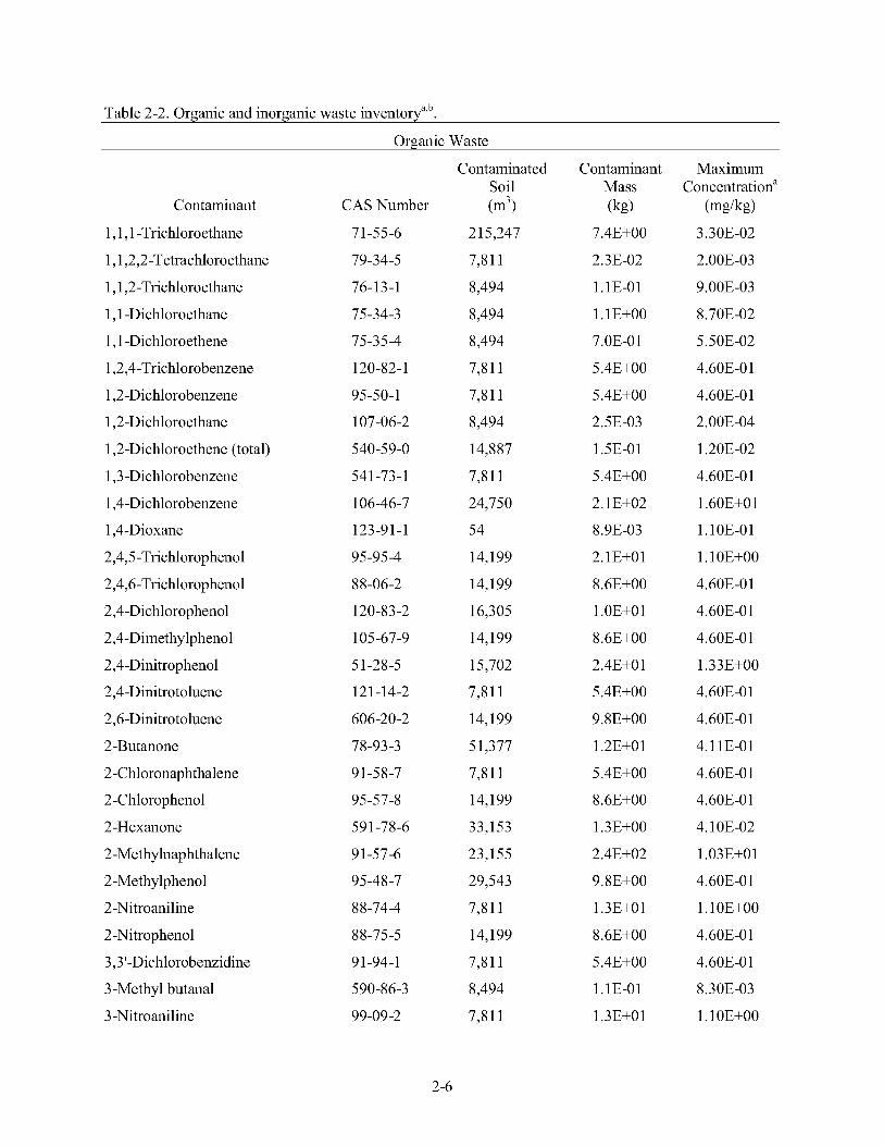
Table 2-2. Organic and inorganic waste inventorya’b.
Organic Waste
Contaminant
1,1,1 -Trichloroethane
1,1,2,2-Tetrachloroethane
1,1,2-Trichloroethane
1,l -Dichloroethane
1,l -Dichloroethene
1,2,4-Trichlorobenzene
1,2-Dichlorobenzene
1,2-Dichloroethane
1,2-Dichloroethene (total)
1,3-Dichlorobenzene
1,4-Dichlorobenzene
1,4-Dioxane
2,4,5-Trichlorophenol
2,4,6-Trichlorophenol
2,4-Dichlorophenol
2,4-Dimethylphenol
2,4-Dinitrophenol
2,4 -Dinitrot0 luene
2,6-Dinitrotoluene
2-Butanone
2-Chloronaphthalene
2-Chlorophenol
2-Hexanone
2-Methylnaphthalene
2-Methylphenol
2 -Nitro aniline
2-Nitrophenol
3,3’-Dichlorobenzidine
3 -Methyl butanal
3 -Nitroaniline
CAS Number
71-55-6
79-34-5
76-13-1
75-34-3
75-35-4
120-82-1
95-50-1
107-06-2
540-59-0
541 -73-1
106-46-7
123-9 1-1
95-95-4
88-06-2
120-83-2
105-67-9
5 1-28-5
12 1 -1 4-2
606-20 -2
78-93-3
91-58-7
95-57-8
591-78-6
91-57-6
95 -4 8 -7
8 8-74-4
88-75-5
91-94-1
5 90-8 6 -3
99-09 -2
Contaminated Soil (m’)
215,247
7,811
8,494
8,494
8,494
7,811
7,811
8,494
14,887
7,811
24,750
54
14,199
14,199
16,305
14,199
15,702
7,811
14,199
51,377
7,811
14,199
33,153
23,155
29,543
7,811
14,199
7,811
8,494
7,811
Contaminant Mass (kg)
7.4E+00
2.3E-02
1.1E-01
1.1 E+OO
7.OE-01
5.4E+00
5.4E+00
2.5E-03
1.5E-01
5.4E+00
2.1 E+02
8.9E-03
2.1E+01
8.6E+00
l.OE+Ol
8.6E+00
2.4E+O1
5.4E+00
9.8E+00
1.2E+O 1
5.4E+00
8.6E+00
1.3E+00
2.4E+02
9.8E+00
1.3E+01
8.6E+00
5.4E+00
1.1E-01
1.3E+01
Maximum Concentrationa
(mg/kg) 3.30E-02
2.00E-03
9.00E-03
8.70E-02
5.50E-02
4.60E-0 1
4.60E-0 1
2.00E-04
1.20E-02
4.60E-0 1
1.60E+O1
1.10E-01
1.1 OE+OO
4.60E-0 1
4.60E-0 1
4.60E-0 1
1.33E+00
4.60E-0 1
4.60E-0 1
4.1 1E-01
4.60E-0 1
4.60E-0 1
4.1 OE-02
1.03E+01
4.60E-0 1
1.1 OE+OO
4.60E-0 1
4.60E-0 1
8.3 OE-03
1.1 OE+OO
2-6
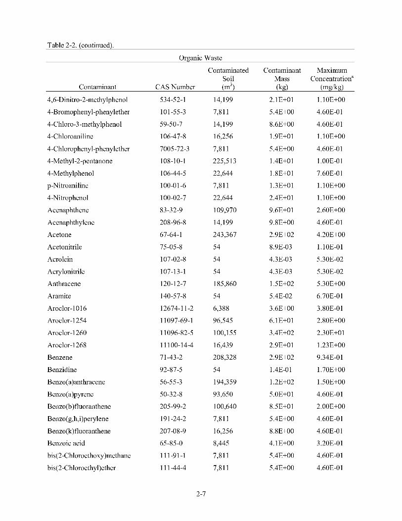
Table 2-2. (continued).
Organic Waste
Contaminated Contaminant Maximum Soil Mass Concentrationa
Contaminant CAS Number (m’) (kg) (mg/kg) 4,6 -Dinitro -2 -methy lpheno 1
4-Bromophenyl-phenylether
4-Chloro-3 -methylphenol
4-Chloroaniline
4-Chlorophenyl-phenylether
4-Methyl-2 -pentanone
4-Methylphenol
p -Nitro aniline
4-Nitrophenol
Acenaphthene
Acenaphthylene
Acetone
Acetonitrile
Acrolein
Acrylonitrile
Anthracene
Aramite
Aroclor-10 16
Aroclor-1254
Aroclor-1260
Aroclor-1268
Benzene
Benzidine
Benzo( a)anthracene
Benzo( a)pyrene
B enzo (b ) fluor anthene
Benzo(g,h,i)perylene
B enzo(k) fluoranthene
Benzoic acid
bis(2-Ch1oroethoxy)methane
bis(2-Chloroethy1)ether
534-52- 1
101-55-3
59-50-7
106-47-8
7005-72-3
108-10-1
106-44-5
100-0 1 -6
100-02-7
83-32-9
208-96-8
67-64-1
75-05-8
107-02-8
107-13-1
120-12-7
140-57-8
12674-1 1-2
1 1097-69-1
1 1096-82-5
11 100-14-4
71-43-2
92-87-5
56-55 -3
50-32-8
205-99-2
19 1-24-2
207-08-9
65-85-0
111-91-1
1 1 1-44-4
14,199
7,811
14,199
16,256
7,811
2253 13
22,644
7,811
22,644
109,970
14,199
243,367
54
54
54
185,860
54
6,388
96,545
100,155
16,439
208,328
54
194,359
93,650
100,640
7,811
16,256
8,445
7,811
7,811
2.1E+01
5.4E+00
8.6E+00
1.9E+01
5.4E+00
1.4E+O 1
1.8E+01
1.3E+01
2.4E+O1
9.6E+O1
9.8E+00
2.9E+02
8.9E-03
4.3E-03
4.3E-03
1.5E+02
5.4E-02
3.6E+00
6.1E+01
3.4E+02
2.9E+O1
2.9E+02
1.4E-0 1
1.2E+02
5.OE+O 1
8.5E+O 1
5.4E+00
8.8E+00
4.1E+00
5.4E+00
5.4E+00
1.1 OE+OO
4.60E-0 1
4.60E-0 1
1.1 OE+OO
4.60E-0 1
1.00E-01
7.60E-0 1
1.1 OE+OO
1.1 OE+OO
2.60E+00
4.60E-0 1
4.20E+00
1.10E-01
5.30E-02
5.30E-02
5.3 OE+OO
6.70E-0 1
3.80E-0 1
2.80E+00
2.30E+O 1
1.23E+00
9.34E-0 1
1.70E+00
1.50E+00
4.60E-0 1
2.00E+00
4.60E-0 1
4.60E-0 1
3.20E-01
4.60E-0 1
4.60E-0 1
2-7
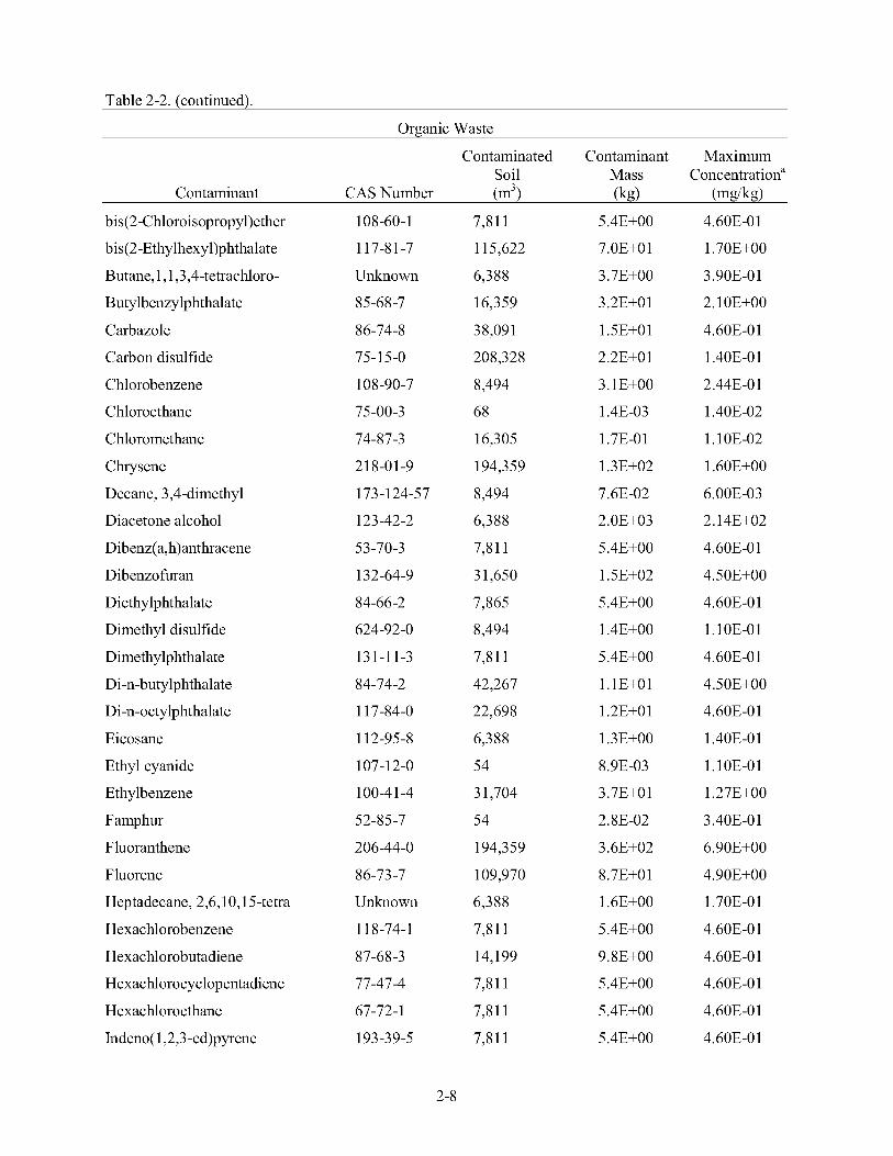
Table 2-2. (continued).
Organic Waste
Contaminated Contaminant Maximum Soil Mass Concentrationa
Contaminant CAS Number (m’) (kg) (mg/kg)
bis(2-Chloroisopropy1)ether
bis(2-Ethylhexy1)phthalate
Butane,l, 1,3,4-tetrachloro-
Butylbenzylphthalate
Carbazole
Carbon disulfide
Chlorobenzene
Chloroethane
Chloromethane
Chrysene
Decane ,3,4 -dimethyl
Diacetone alcohol
Dibenz( a,h)anthracene
Dibenzo furan
Diethylphthalate
Dimethyl disulfide
Dimethylphthalate
Di-n-butylphthalate
Di-n-octylphthalate
Eicosane
Ethyl cyanide
Ethylbenzene
Famphur
Fluoranthene
Fluorene
Heptadecane, 2,6,10,15-tetra
Hexachlorobenzene
Hexachlorobutadiene
Hexachlorocyclopentadiene
Hexachloroethane
Indeno( 1,2,3-cd)pyrene
108-60-1
1 17-8 1-7
Unknown
85-68 -7
86-74-8
75-15-0
108-90-7
75-00-3
74-87-3
21 8-01 -9
173-1 24-57
123-42-2
53-70-3
132-64-9
84-66 -2
624-92-0
131-11-3
84-74-2
1 17-84-0
112-95-8
107-12-0
100-4 1-4
52-85-7
206-44-0
86-73-7
Unknown
11 8-74-1
87-68-3
77-47-4
67-72-1
1 93 -3 9-5
7,811
115,622
6,388
16,359
38,091
208,328
8,494
68
16,305
194,359
8,494
6,388
7,811
3 1,650
7,865
8,494
7,811
42,267
22,698
6,388
54
3 1,704
54
194,359
109,970
6,388
7,811
14,199
7,811
7,811
7,811
5.4E+00
7.OE+O1
3.7E+00
3.2E+O 1
1.5E+01
2.2E+O1
3.1E+00
1.4E-03
1.7E-01
1.3E+02
7.6E-02
2.OE+03
5.4E+00
1.5E+02
5.4E+00
1.4E+00
5.4E+00
1.1E+01
1.2E+O 1
1.3E+00
8.9E-03
3.7E+01
2.8E-02
3.6E+02
8.7E+O 1
1.6E+00
5.4E+00
9.8E+00
5.4E+00
5.4E+00
5.4E+00
4.60E-0 1
1.70E+00
3.90E-01
2.1 OE+OO
4.60E-0 1
1.40E-01
2.44E-01
1.40E-02
1.1 OE-02
1.60E+00
6.00E-03
2.14E+02
4.60E-0 1
4.50E+00
4.60E-0 1
1.1 OE-01
4.60E-0 1
4.50E+00
4.60E-0 1
1.40E-01
1.10E-01
1.27E+00
3.40E-01
6.90E+00
4.90E+00
1.70E-01
4.60E-0 1
4.60E-0 1
4.60E-0 1
4.60E-0 1
4.60E-0 1
2-8

Table 2-2. (continued).
Organic Waste
Contaminated Contaminant Maximum Soil Mass Concentrationa
Contaminant CAS Number (m’) (kg) (mg/kg)
Isobutyl alcohol
Isophorone
Isopropyl alcohol/2-propanol
Kepone
Mesityl oxide
Methyl acetate
Methylene chloride
Naphthalene
Nitrobenzene
N-Nitroso-di-n-propylamine
N-Nitro s o diphenylamine
Octane,2,3,7-trimethyl
o-Toluenesulfonamide
Pentachlorophenol
Phenanthrene
Phenol
Phenol,2,6-Bis( 1,l -dimethyl)
p-Toluenesulfonamide
Pyrene
Styrene
Tetrachloroethene
Toluene
Tributylphosphate
Trichloroethene
Undecane,4,6-dimethyl-
Xylene (ortho)
Xylene (total)
78-83-1
78-59-1
67-63-0
143-50-0
14 1-79-7
79-20 -9
75 -09 -2
9 1-20-3
98-95-3
62 1-64-7
86-3 0-6
62016-34-6
88-19-7
87-86-5
85-01-8
108-95-2
Unknown
70-55-3
129-00-0
100-42-5
127-18-4
108-88-3
126-73-8
79-0 1-6
173 12822
95 -47 -6
1 3 3 0-20 -7
54
7,865
9,572
78,320
6,388
8,494
204,802
31,601
7,811
7,811
7,811
8,494
6,388
31,138
194,360
22,698
6,388
6,388
103,124
54
224,494
239,746
249,578
227,010
8,494
245,243
23 1,537
8.9E-03
5.4E+00
1 .OE+OO
4.7E+O1
4.OE+O1
2.3E-01
4.OE+O1
2.OE+02
5.4E+00
5.4E+00
5.4E+00
7.6E-02
2.4E+00
2.6E+O1
5.5E+02
3.8E+O 1
1.9E+00
2.4E+00
1.2E+02
4.9E-04
4.6E+00
4.7E+02
1.7E+02
3.4E+O 1
7.6E-02
1.8E+00
1.6E+03
1.10E-01
4.60E-0 1
7.00E-02
4.00E-0 1
4.19E+00
1.80E-02
2.90E-0 1
7.80E+00
4.60E-0 1
4.60E-0 1
4.60E-0 1
6.00E-03
2.50E-0 1
1.1 OE+OO
1.60E+01
2.3 OE+OO
2.00E-0 1
2.50E-0 1
6.40E+00
6.00E-03
1.30E-0 1
8.3 3E+00
4.60E-0 1
2.00E-0 1
6.00E-03
5.00E-03
4.3OE+O 1
Ytterbium 7440-64-4 42,164 9.2E+04 4.00E+03
2-9
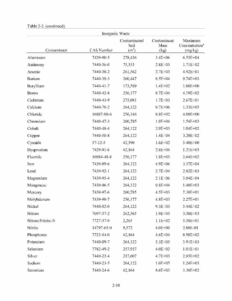
Table 2-2. (continued).
Inorganic Waste
Contaminated Contaminant Maximum Soil Mass Concentrationa
Contaminant CAS Number (m’) (kg) (mg/kg) Aluminum
Antimony
Arsenic
Barium
Beryllium
Boron
Cadmium
Calcium
Chloride
Chromium
Cobalt
Copper
Cyanide
Dysprosium
Fluoride
Iron
Lead
Magnesium
Manganese
Mercury
Mo 1 yb denum
Nickel
Nitrate
Nitratemitrite-N
Nitrite
Phosphorus
Potassium
Selenium
Silver
S odium
Strontium
7429-90-5
7440-36-0
7440-38-2
7440-39-3
7440-4 1-7
7440-42-8
7440-43-9
7440-70-2
16887-00-6
7440-47-3
7440-48-4
7440-50-8
57-12-5
7429-9 1-6
16984-48-8
7439-89-6
7439-92-1
7439-95-4
7439-96-5
7439-97-6
7439-98-7
7440-02-0
7697-37-2
7727-37-9
14797-65-0
7723-14-0
7440-09-7
7782-49-2
7440-22-4
7440-23-5
7440-24-6
278,436
75,353
261,562
260,447
173,589
256,177
275,081
264,122
256,146
260,785
264,122
264,122
42,390
42,164
256,177
264,122
264,122
264,122
264,122
260,785
256,177
264,122
262,565
2,265
9,572
42,164
264,122
257,937
21 7,607
264,122
42,164
6.53E+04
1.7 1 E+02
4.92E+0 1
9.74E+03
1.80E+00
4.19E+02
2.67E+0 1
1.33E+05
4.00E+00
1.54E+03
1.04E+02
3.20E+02
3.40E+00
1.2 1 E+03
2.64E+02
3.37E+04
2.82E+03
3.04E+04
1.40E+03
7.3 8E+O 1
2.27E+01
3.44E+02
3.30E+03
3.38E+Ol
2.80E-0 1
8.98E+02
3.91E+03
1 .O 1 E+O 1
2.95E+02
1.24E+03
3.3OE+02
2-1 0
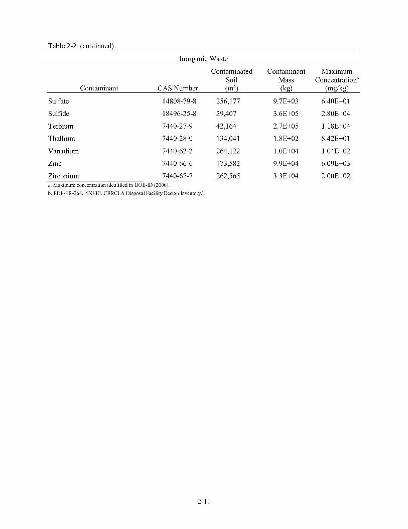
Table 2-2. (continued).
Inorganic Waste
Contaminated Contaminant Maximum Soil Mass Concentrationa
Contaminant CAS Number (m’) (kg) (mg/kg)
Sulfate 14808-79-8 256,177 9.7E+03 6.40E+O 1
Sulfide 18496-25-8 29,407 3.6E+05 2.80E+04
Terbium 7440-27-9 42,164 2.7E+05 1.18E+04
Thallium 7440-28-0 134,041 1.8E+02 8.42E+0 1
Vanadium 7440-62-2 264,122 1 .OE+04 1.04E+02
Zinc 7440-66-6 173,582 9.9E+04 6.09E+03
Zirconium 7440-67-7 262,565 3.3E+04 2.00E+02 a. Maximum concentration identified in DOE-ID (2000).
b. EDF-ER-264, “INEEL CERCLA Disposal Facility Design Inventory.”
2-1 1

x
z v 2
; I rn
x
z v 2
; I rn
i
a
2-12

x
z m 2
; I rn
E E
rn .e
d)
E 9 d)
8 3 .- Q i
i
Li d) >
bn
e- “, i
2-13
i
x
z m 2
; I rn
E a
i
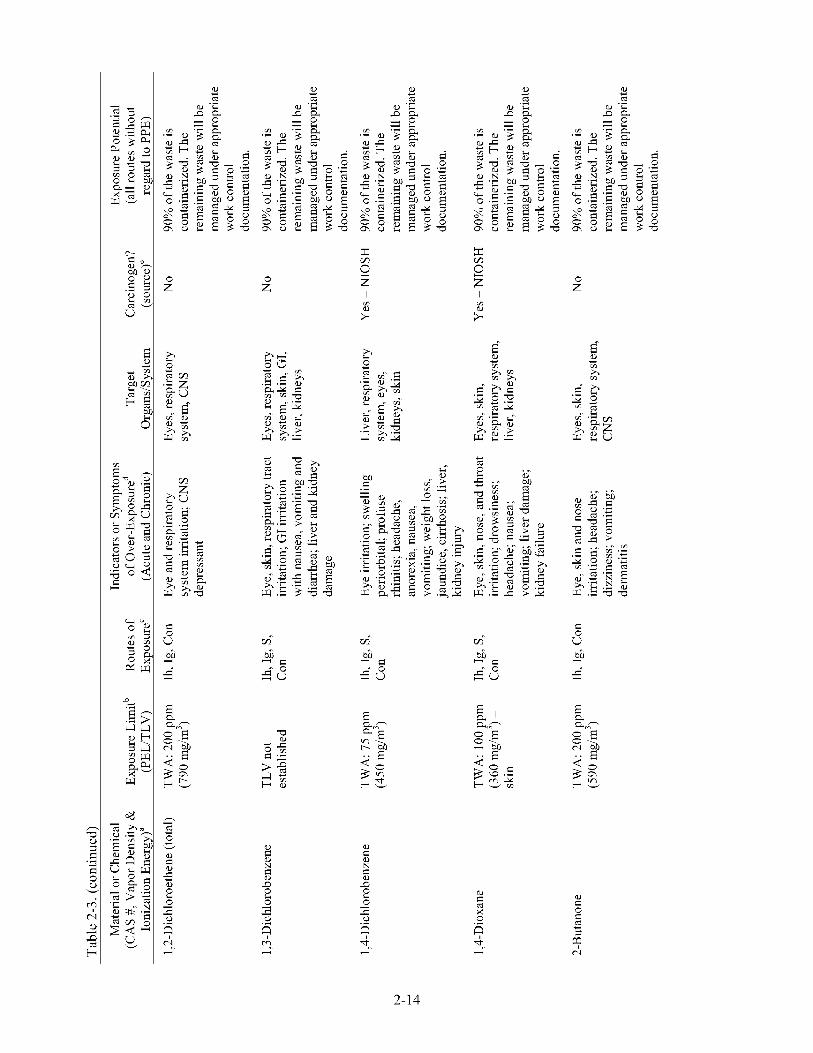
E
“. i
E x
z rn 2
; I rn
x Li 0
i
x
z rn 2
; I rn
i i
2-14
s 8
Q x 0 .-
i
E

E
z 'OD, F s
H Z 2 5
E 2
2-15

i
0
o a x i e
c; 2
2-16
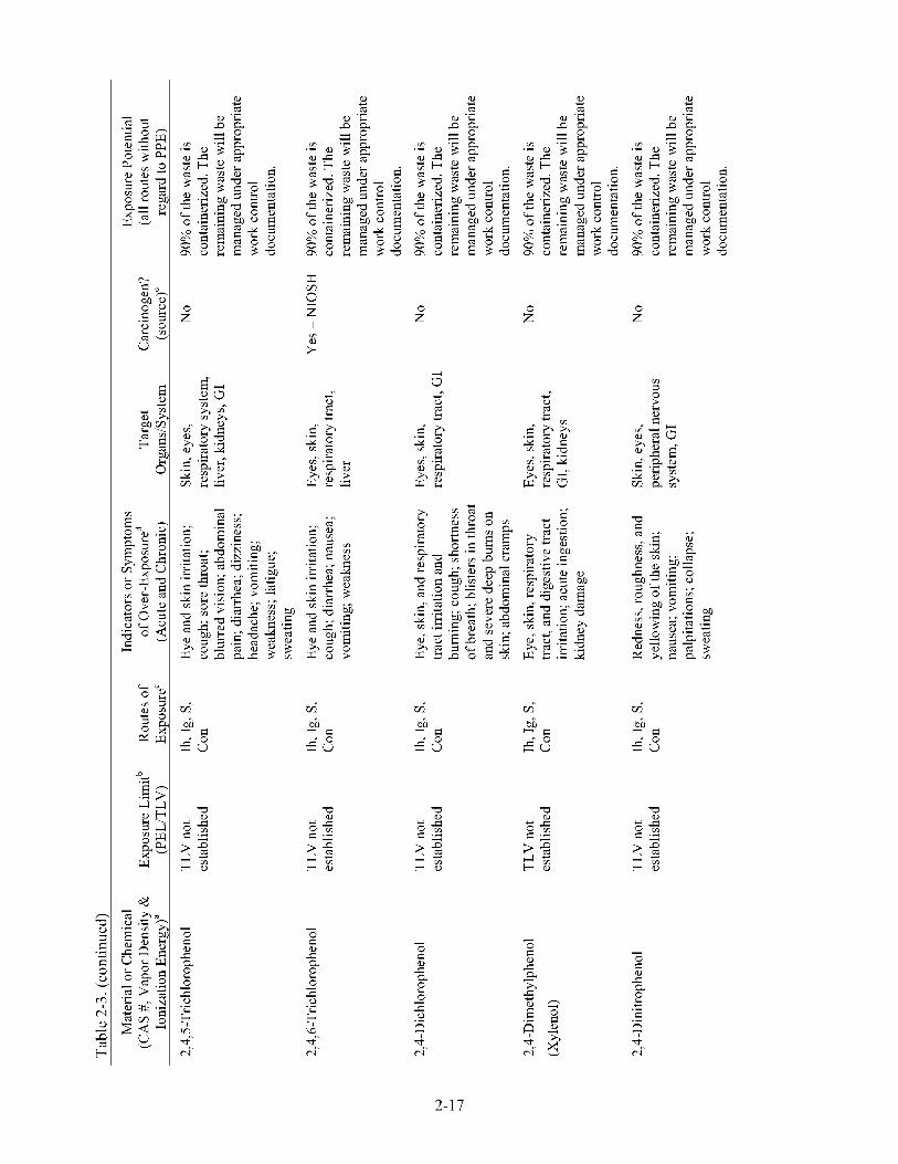
E
5 4- 0 E Y
E E
K?
z 'OD, F s
H 2 2 5
z 'OD, F s
H 2 2 5
e- m
2-17
z 'OD, F s
H 2 2 5
a a, 'OD, F s
H 2 2 5
e- m

x
z rn 2
I
x
z rn 2
I E rn rn
; ; H r k
x
a- m
E
rn x
-0 2 22 -0-
a 0 0 i
2-1 8

E
Y
g L i d) .- u >
3
z v 8 Tt
a z 'OD, F s
H Z 2 5
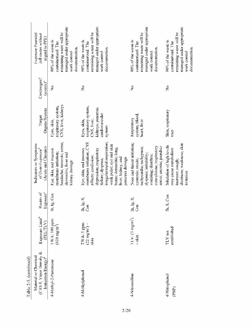
8
0-
u 6 H
E E E
i
0
o a x
r3
e Ti
i
2
n
"E a E rc
Ti
2-20
8 u

E E
Y
2-2 1
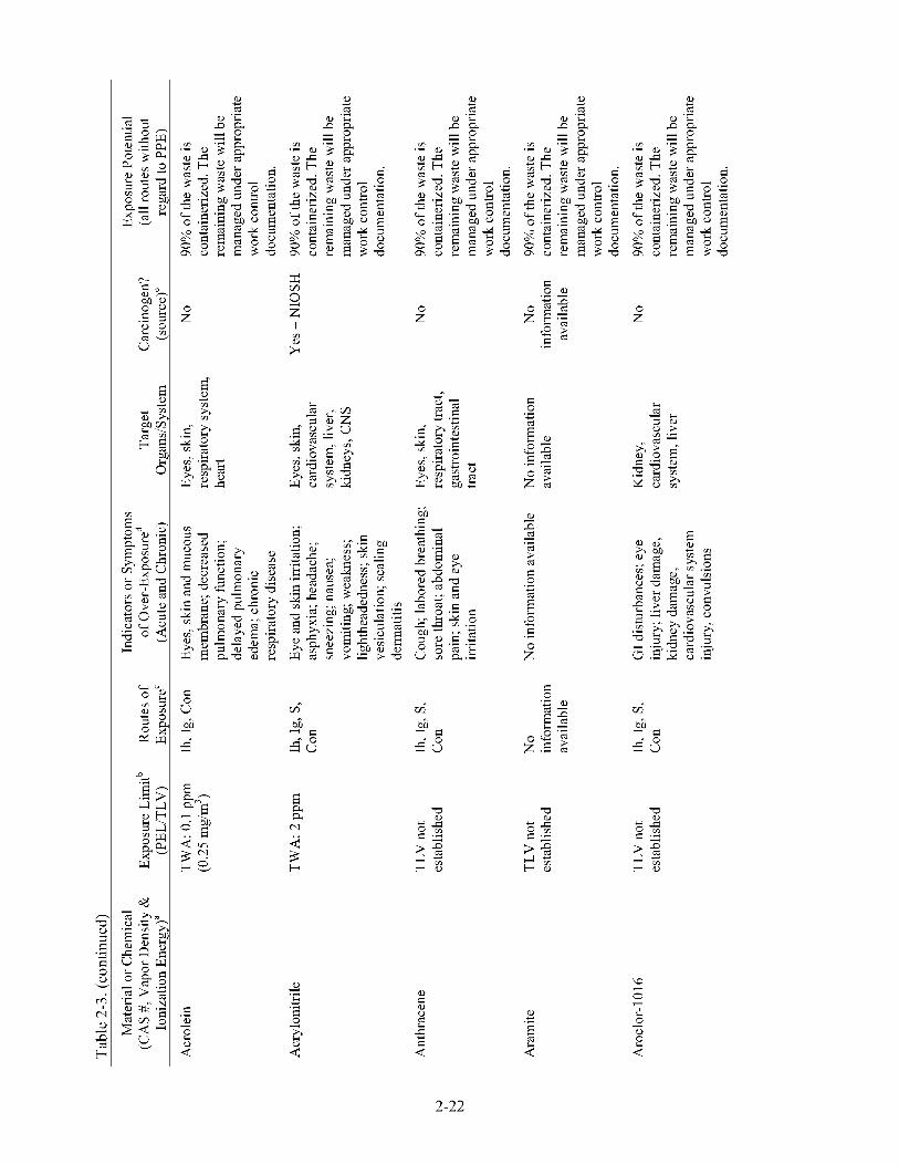
x
z v 2
; I rn
vi 8 u 6 H
0-
.. Li
E d) .- i
E 4
6 H 8 0- u
E
d)
0 a i- 2
E
a
a 0 i
i
2-22
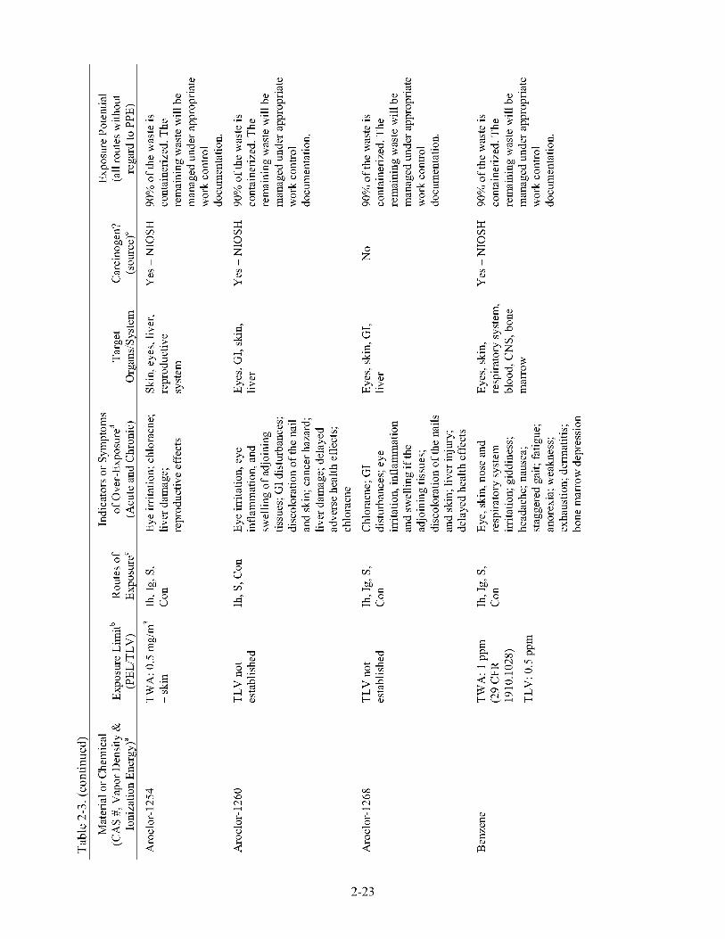
z 'OD, F l s l
H Z 2 5
0 a PJ i
i 6 3 0
00 a PJ i
d)
N
E m
2-23

mi 6 H 8 0- u
2 5 E a N
mi 6 H 8 0- u
E
.- 8
E
8 u
a
d)
E i x a Li d)
2-24

E
bn H
0-
2-25
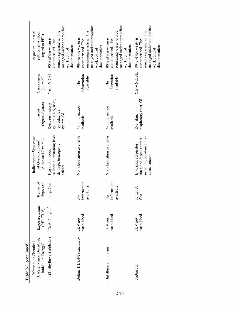
x
z rn 2
; I rn
Li d) > .- i
h i
x x
x d)
A 4
d) d)
9 9 a a a a > > a a
i i
i .- i .-
Li Li e e F .e F .e
E E
z ’OD, F s
H Z 2 5
i
2-26

E E x
z rn 2
; I rn
E a 0 PJ .. 4 3 b
d) m CL 5 i
rn .- n 8 2 9
u
d)
N
9
E E
a u 8
E a 0 2 ;d 3 b
2-27
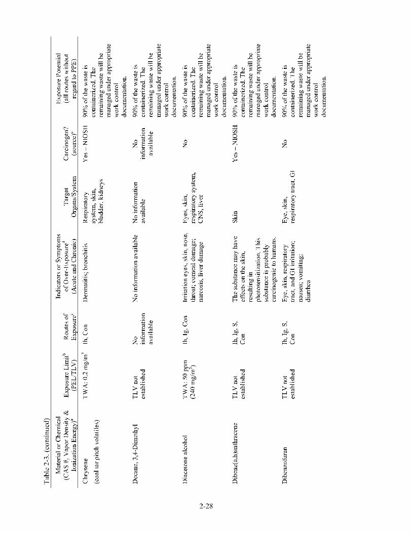
i
0 0 0 0 cs i
x
z rn 2
; I rn
E
a
2-28
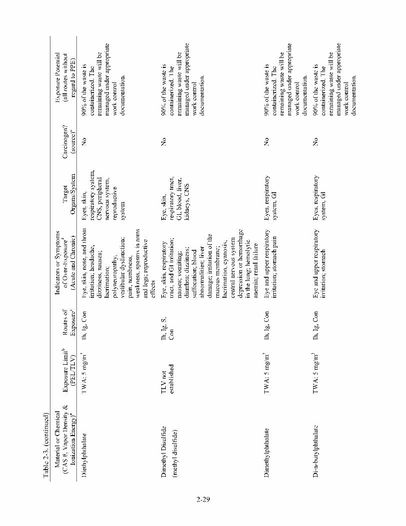
E E
8 u 8 u
E
“E a E
d)
cs cs 4-
i
a i
2-29
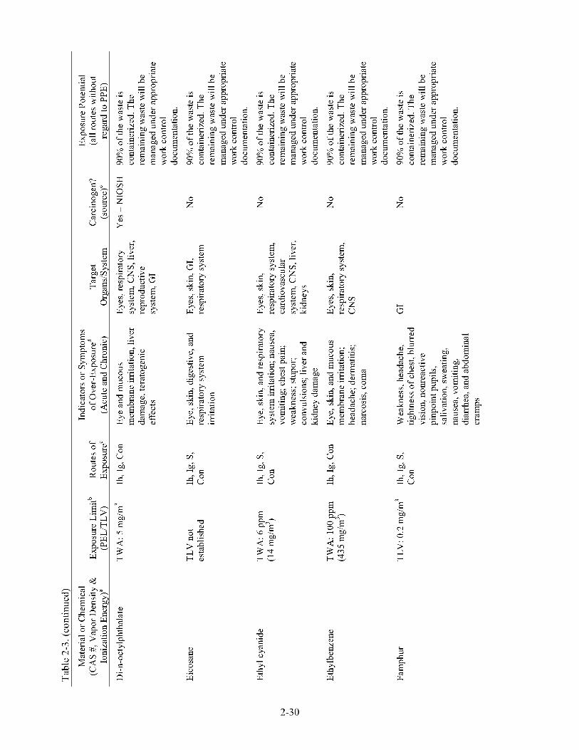
E E E E
-0 8
u 6 H
0-
“E \
2 a 0 0 .e w
5 o B cs
Fr,
2-30
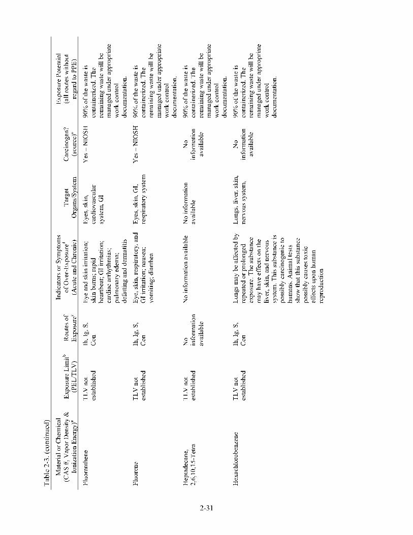
x x
z z rn rn
2 2
; ; I I rn rn
3 i
z ’OD, F l s l
H Z 2 5
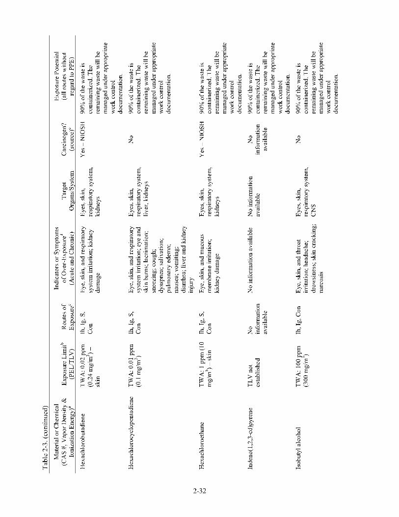
2-32

E E E
8
0-
u 6 H
8 u u 6 H
0- 6 H
0-
i 0
s z x 0 i
2-33
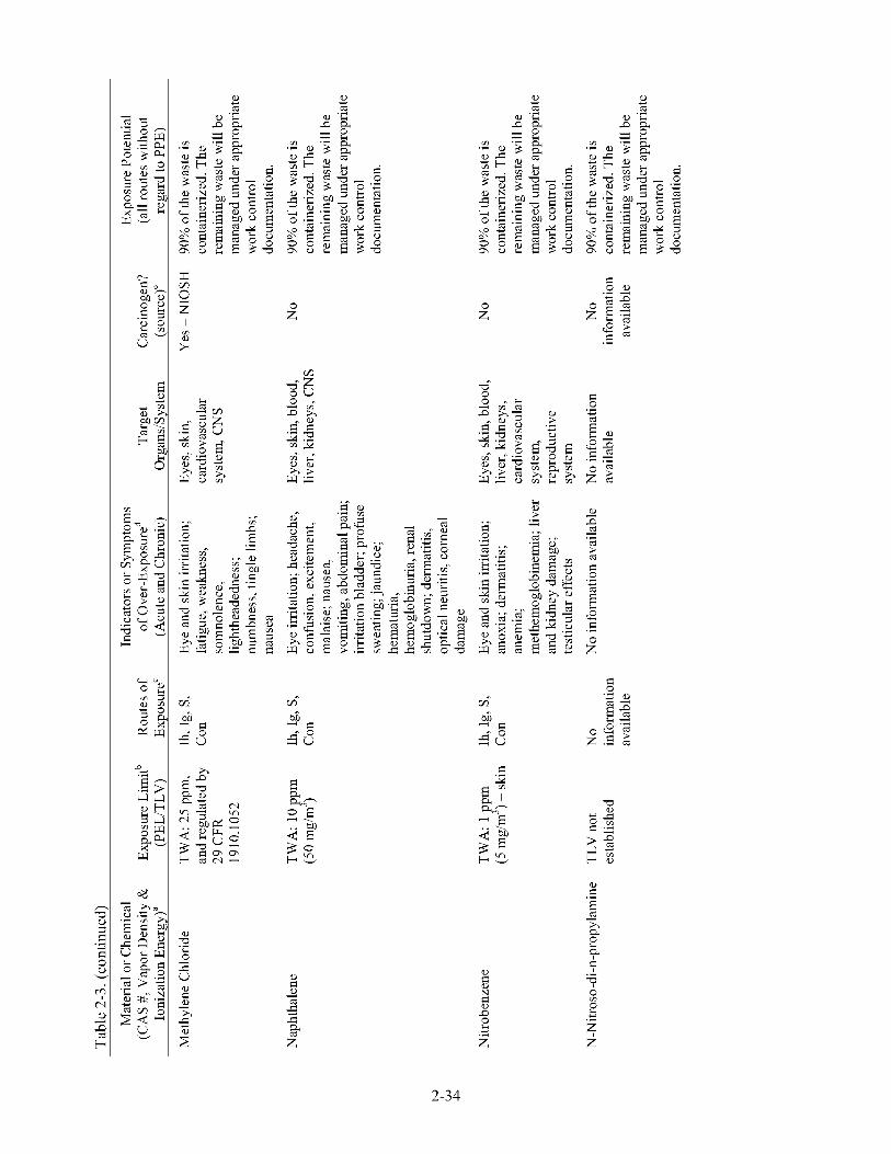
2-34

x
z rn 2
; I rn
z 'OD,
H Z
F s
2 5
2-35
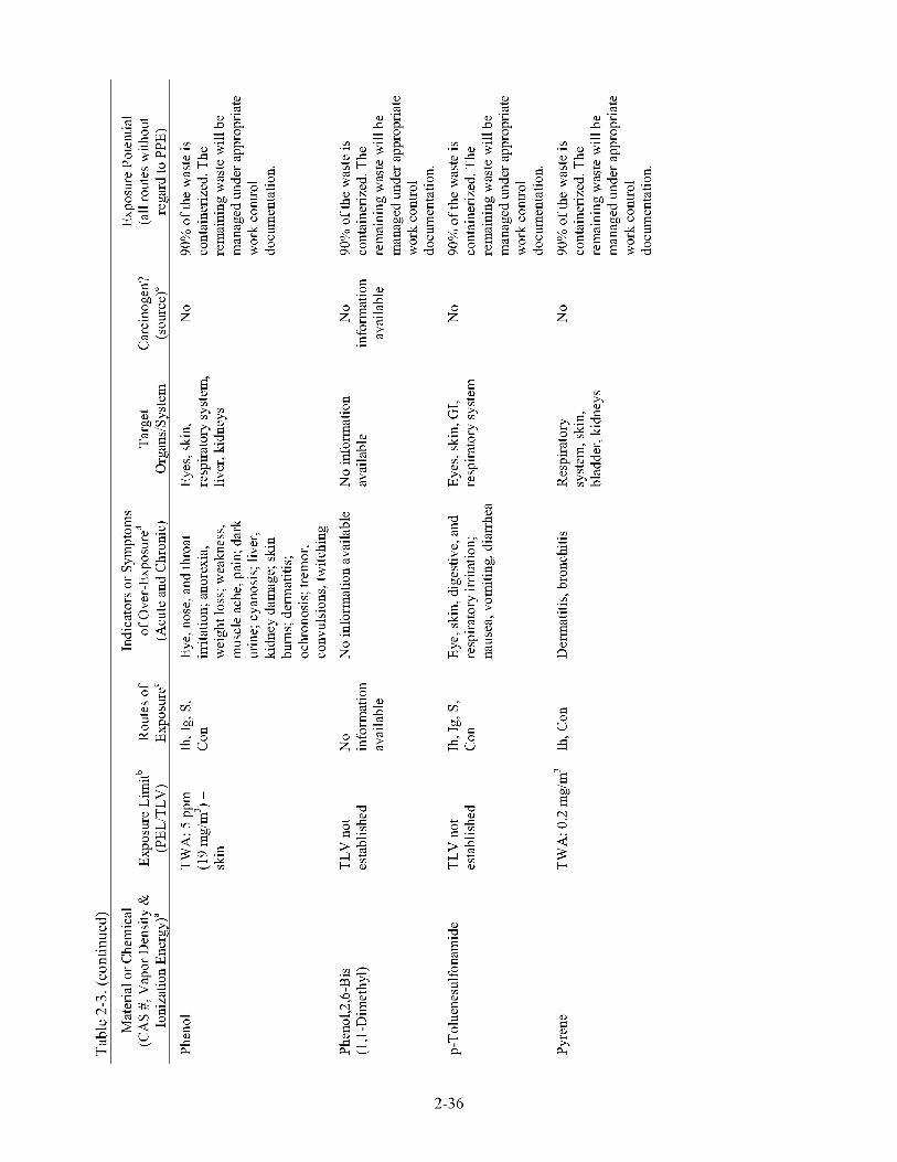
E E
4- E H- rn 0 2
z ’OD, F s
H Z 2 5
? a
E
“E a E
d)
L K
2-36

E E
E a 0 2 ;d 3 b
d)
K j;
E a 0 2 ;d 3 b
E a 0 0 PJ
;d 3 b
2-37

a- *.
J
E E
n 0 e 8
E W
s
i
x"
n cs 0
s
i
4-
4- W
E i
x"
2-3 8
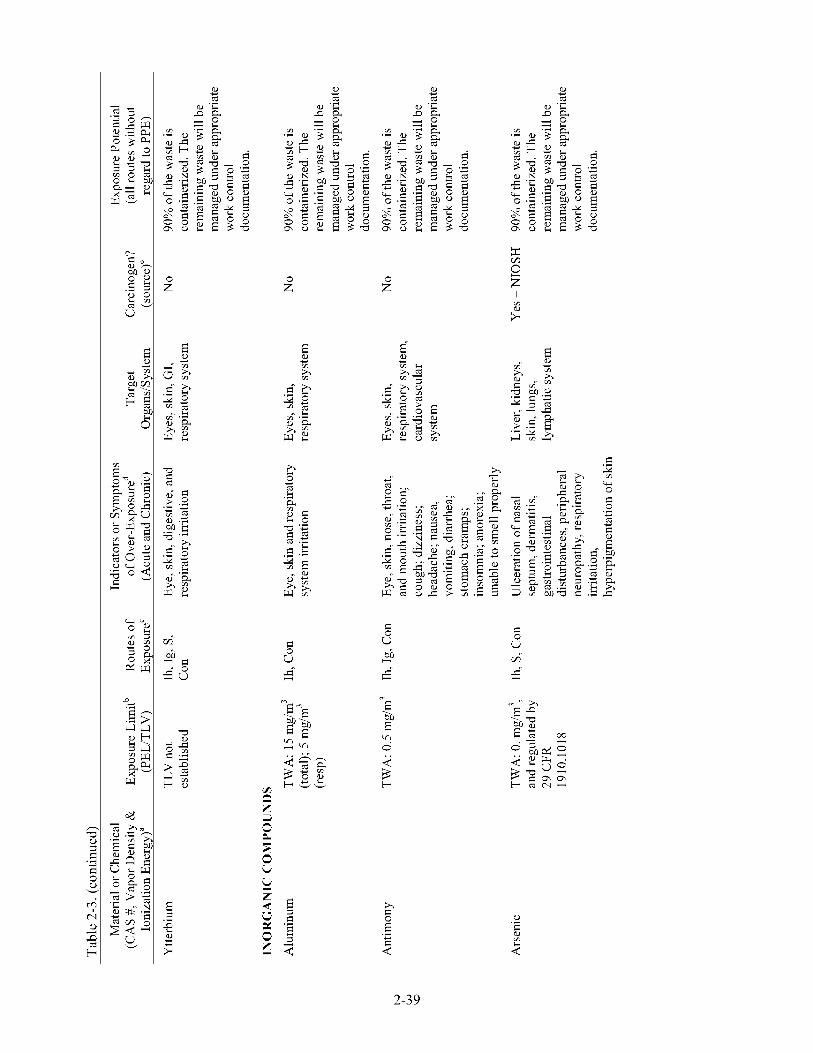
E E
Y 0 .- E 2 rn
2-39

E E
rn d) x w
t- \
2 Fi
z ’OD, F s
H Z 2 5
bn H
0-
a a, ’OD, F s
H Z 2 5
2-40
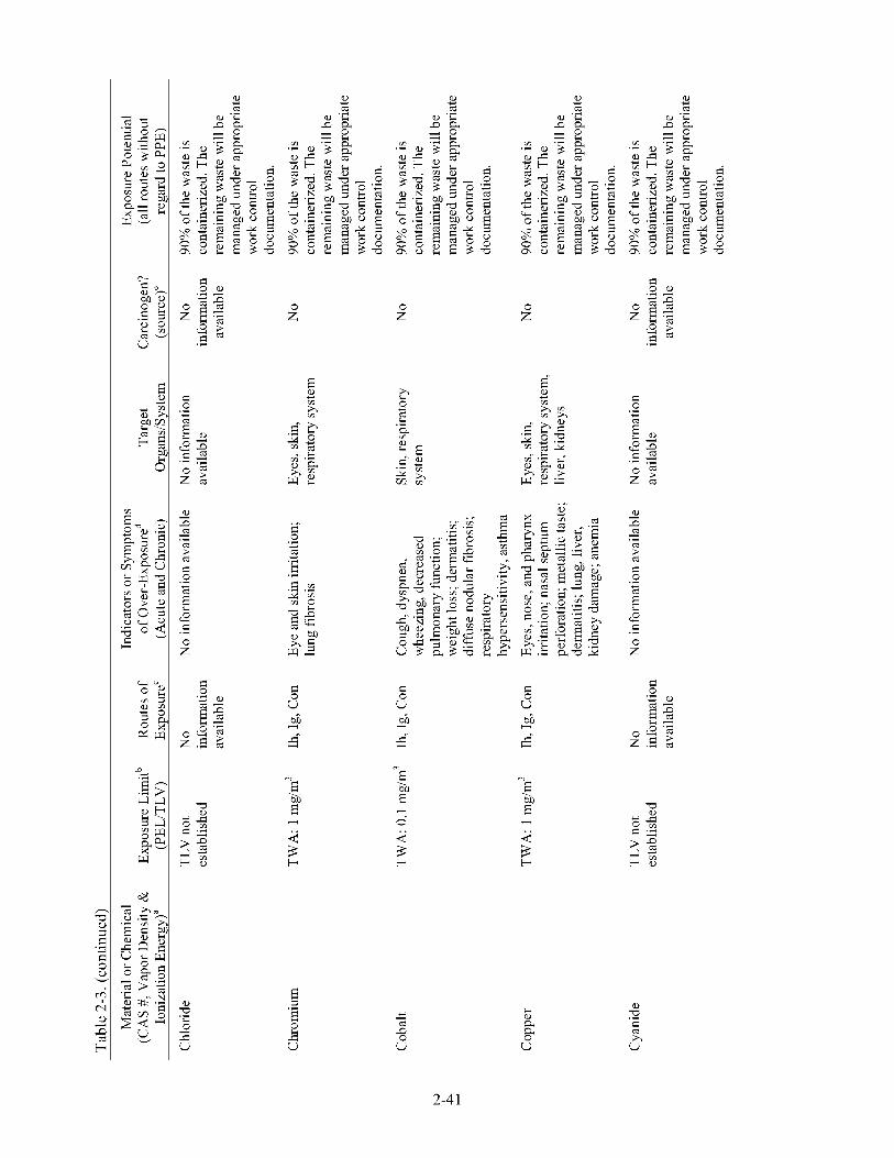
E
E
8 u 6 H
0-
“E a E i
;d 3 b
E E
Li d) a 8 u
a
2-4 1

E
z ’OD,
H Z
F Z
2 5
E E
8 u 6 H
0-
8 u 6 H
0-
In .. 4 3 H
F E H
2-42
Li , 2 Fi

E E
rn
E
bn H
0-
“E a E i
;d 3 b
s rn s 8 bn
4
b5 H
0-
2-43

d)
cs 4-
d) 'rl s a
d)
cs 4-
d) 'rl s a
E
d)
9 cs cs > cs
i
i .e
8 E
E
.e 4- cs
e F .e
d)
9 cs cs > cs
i
i .e
8 E
E
.e 4- cs
e F .e
E
"E a E
2-44

E E
8
0-
u 6 H
“E
2 a E
;d 3 H
8
0-
u 6 H
“E ; d E 3G
a
H O
2-45
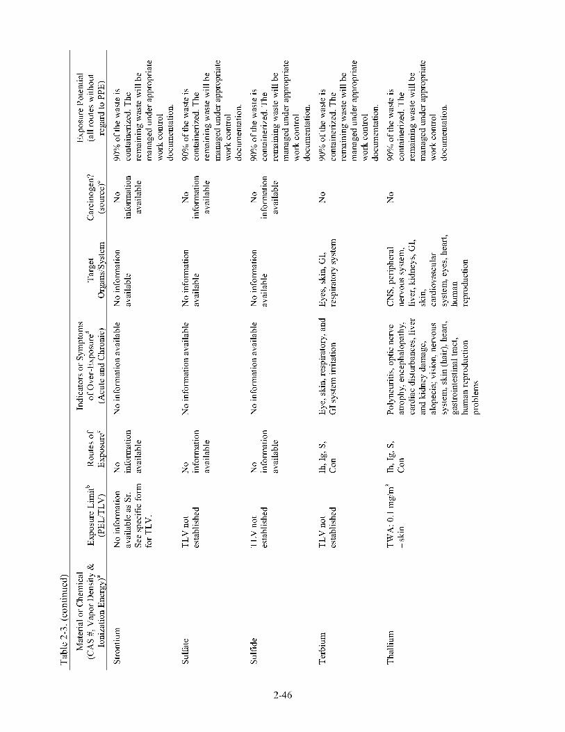
E
d)
9 a a > a
i
i .-
8 E
E
.- 4- a
e F .-
z ’OD,
H Z
F Z
2 5
d) 4-
& i
5 rn
d) -0 CL 5 rn i
E
2-46
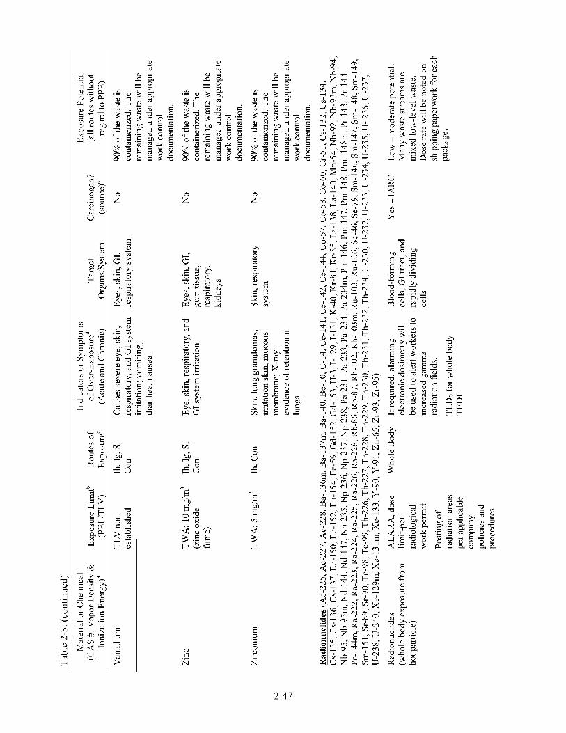
E
m B
.- a- E
m * Z
.- N
E
8 0- u
"E a E
;d 3
m
b
e- $ 5
0 i+
.e rn i
x m 0
d)
0 0
a
3 i
2-47

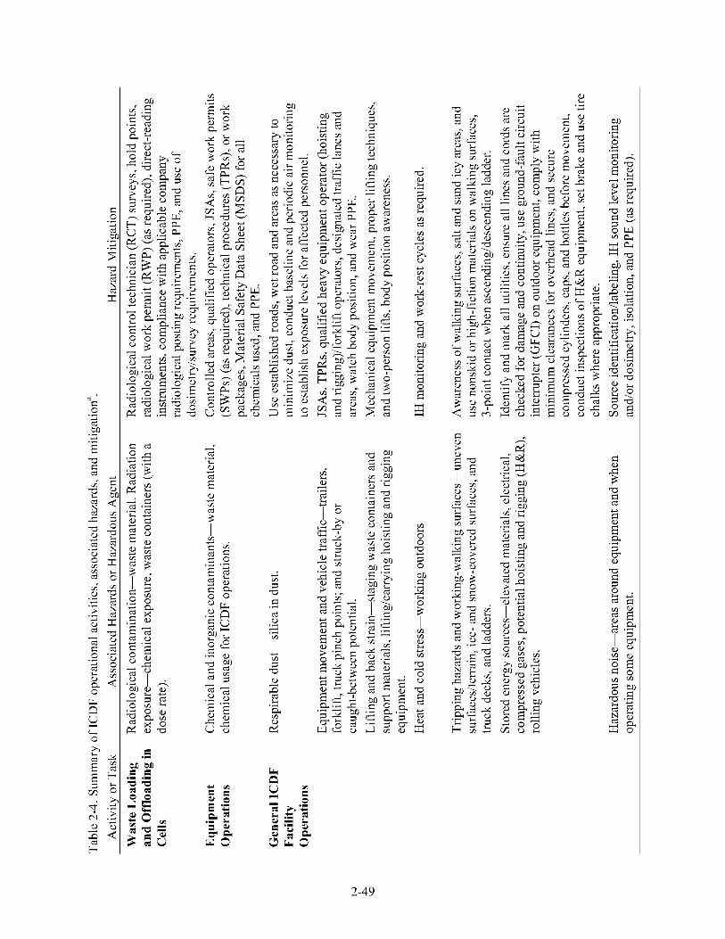
m s C .- + s E .- .- +
T s CT
U
T E. CT J T + CT c .- 5
B CT
.- .- + s .- + c CT
CT - s C .- + CT
!i S C
E k
i E
% C s
5 7
< c. a
F
-
d 0
cd bl
. A Y
. A Y . A z % i? N
Y
g 2
% i?
rA 3 0
N
Li 0
2 N
i? z s: 2
Y
. A cd 0
A
b 0 > >
rA cd
Li
Y . A
. A Y
4
E .C
v1
i
. A cd Li b) Y
8 b)
rA cd Y
3 I
bu d
- 0 0 'rl
Y rA 3 a d cd 0
. A
. A i . A
Y 'i rA 3 a b) s E %
. A
2
cr P
a g
g 2
. A
3 5
rA b)
0
0
rA
i
h Y
G A 0
a
bu d
0
d
Li
3
9 . A Li
Y . A
: 8
rA Li 0 0
3 0 bu d A 0
3
. A
Li
3 rA rA
Y rA
2
9
0 0 a Y cd
x"
E
E h
2-49

Y rA
3 d cd 0
. A
. A i . A
Y ‘i rA 3 a b) s E %
. A
2
2-50

a 9 a
g
g 2 5
s: 9 3
. A
3 5
rA
i
d
Li b)
0
Y
bu d bu bu
bu d
. A
. A Li
'E 2
9 0 a
bu d > . A
z d
. A e Y rA .2 0 cd e a
bu d
cl
9
5 . A
a g
g 2
. A
3 5
rA b)
0
0
rA
i
h Y
G .2 0
a
bu d
0
d
Li
3
9 . A Li
Y . A
z E
rA Li 0 0
3 0 bu d .2 0
3
. A
Li
3 rA rA
Y rA
2
9
0 0 a Y cd
x" E 0
cd E
.C c,
a B B 2
. A
3 5
rA b)
0
0
rA
i
h Y
G .2 0
a
bu d
0
d
Li
3
9 . A Li
Y . A
z E
E
9
3
L d
a . A
rA Li 0 0
3 0 bu d .2 0
. A
Li
3 rA rA
Y rA
2
9
0 0 a Y cd
x"
2-5 1
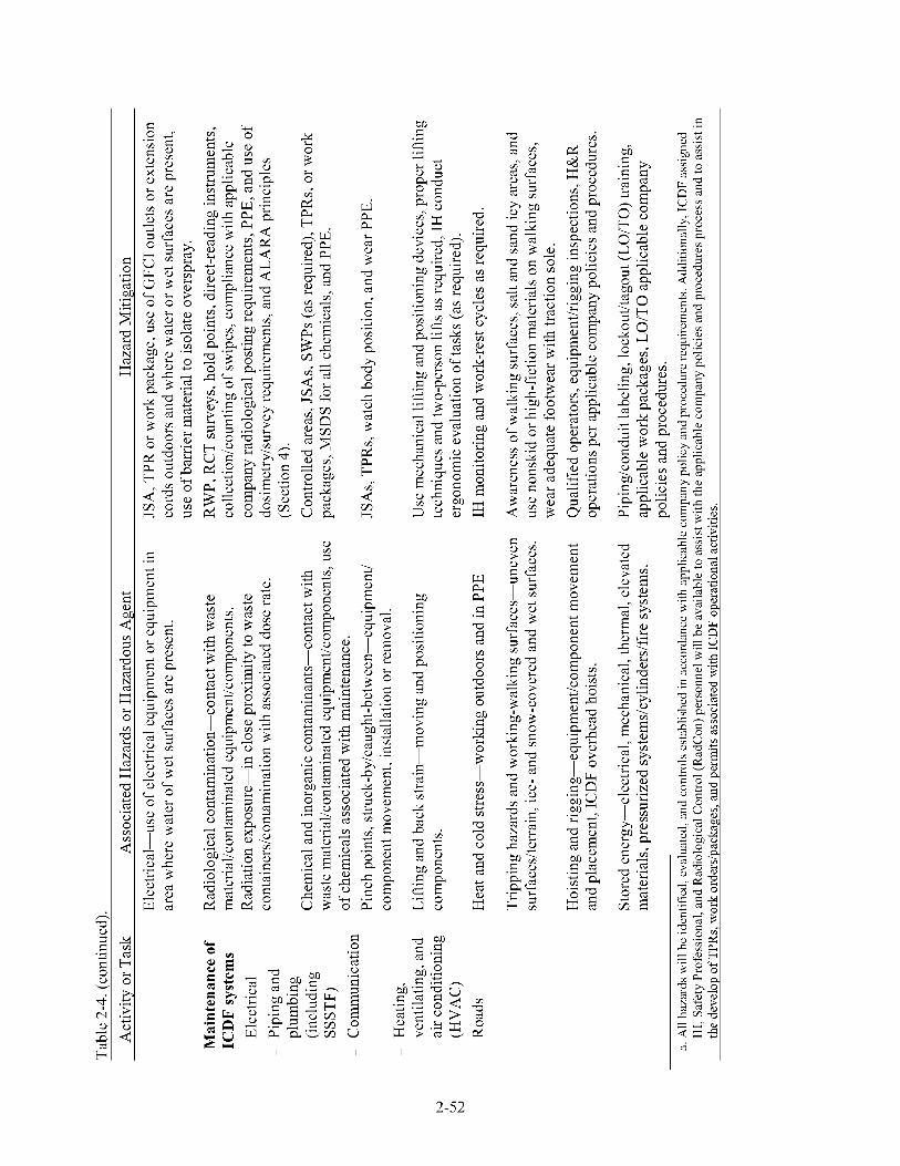
b;
w
s 3
9 d
L L
b)
a
0 . A Y . A
rA 0 a h a 0 e 9 3 Y cd
rAn
b E 2- 2
'4
bu d
. A a
bu d d 0
. A
. A Y . A
rA 0 a a
bu d >
9 . A
z d
. A
E Y rA
0 cd .2
s u i - 5 -
buo d a
c l 0
9 2
g g
E
9
3
L d
a . A
rA Li 0 0
3 0 bu d .2 0
. A
Li
3 rA rA
Y rA
2
9
0 0 a Y cd
x" d 0
. A Y
2-52
2.1.1 Routes of Exposure
Exposure pathways exist for radiological and nonradiological contaminants encountered during ICDF operations. Engineering controls, monitoring, training, and work controls will mitigate potential contact and uptake of these hazards; however, the potential for exposure to contaminants still exists. Exposure pathways include those listed below:
Inhalation of radiological and nonradiological contaminated soil or fugitive dusts during waste handling, disposal, or decontamination tasks. Inhalable or respirable (dependent on the particle aerodynamic diameter) fugitive dusts may have trace amounts of radiological or nonradiological contaminants associated with them, resulting in potential respiratory tract deposition.
Skin absorption and contact with radiological and nonradiological contaminated soil or surfaces during waste handling, disposal, decontamination, or system maintenance tasks. Radiological and nonradiological contaminants can be absorbed through the skin, resulting in uptake through the skin and/or skin contamination.
Ingestion of radiological and nonradiological contaminated soil or materials adsorbed to dust particles or waste residues, resulting in potential uptake of contaminants through the gastrointestinal (GI) tract that may result in GI irritation, internal tissue irradiation, and/or deposition to target organs.
Injection of radiological and nonradiological contaminated materials by breaking of the skin or migration through an existing wound, resulting in localized irritation, contamination, uptake of soluble contaminants, and deposition of insoluble contaminants.
Chemical and radiological hazards will be eliminated, isolated, or mitigated to the extent possible during all ICDF operations. Where they cannot be eliminated or isolated, monitoring for chemical and radiological hazards will be conducted (as described in Section 3) to detect and quantify exposures. Additionally, administrative controls, training, work procedures, and protective equipment will be used to further reduce the likelihood of exposure to these hazards. Table 2-4 summarizes each primary operational activity, associated hazards, and mitigation procedures.
The JSAs, SWPs, radiological work permits (RWPs), and TPRs will be used in conjunction with this HASP to address specific hazardous operations (e.g., hot work) and radiological conditions for ICDF operations. When used, these permits will further detail specialized PPE and dosimetry requirements.
2.2 Radiological Exposure Control
Radiation exposure limits are based on requirements contained in Subpart C of 10 CFR 835 and company policies and procedures. An administrative control level has been established for the INEEL. For nonaccident conditions, company management must give prior written approval for doses greater than the INEEL administrative control level. The administrative limit imposed by DOE is to keep worker exposure less than 2 redyr . DOE-HQ management must give prior written approval for doses greater than 2 redyr , but a worker will not be authorized to receive an exposure greater than 5 redyr . In addition, radiation workers have assigned ALARA goals. The dose limits and ALARA goals are implemented in company procedures and apply to occupational radiation dose, which excludes doses from background, therapeutic and diagnostic radiation, medical radiation, and participation as a subject in medical research programs.
2-53

The radiation dose limit for the unrestricted public exposure scenario (i.e., Highway 26 Rest Area visitor) and the member of the public entry (i.e., INEEL visitor, ICDF visitor) is 0.015 redyear. This dose limit is developed for members of the public who are unknowingly exposed to radiation and is approximately equivalent to an excess lifetime cancer risk of 1 x enter fenced areas of the ICDF Complex but will be restricted to administrative areas only, until they have been through appropriate awareness training. Until such training has been completed visitors will be denied access to Radiological Buffer Areas (RBAs), Radiological Areas, or Contamination Areas to ensure they have no radiological exposure.
The visitors may be permitted to
It is anticipated the average visitor to the ICDF landfill will not enter Controlled Radiation Areas. Visitors allowed to enter Controlled Radiation Areas will be escorted by trained ICDF personnel. The visitor will be provided information on radiation exposures, radiation doses, anticipated levels of exposure based upon visit duration, and area levels; and the visitor must be willing to accept the risks of radiation exposure. This training will be conducted prior to and every time the visitor is allowed access the site. These escorted visitors will be provided radiation dosimetry to maintain exposure records within occupational protective levels. Radiological exposures will be mitigated to acceptable levels that are protective of occupational personnel. Because occupational personnel exposure are maintained below established limits, the visitor is also protected due to reduced exposure frequency and duration
The total effective dose equivalents for the nonradiation worker scenarios are far below the radiation dose limit of 0.1 redyear. It is important to note that the total effective dose equivalent values calculated for the nonradiation worker exposure scenarios are based on unmitigated risk. In no event will workers be allowed to exceed the regulatory limit of 0.1 redyear for occupational exposures. By accepting the dosimeter, the visitor has accepted the risk of possible exposure and is automatically entered into the INEEL dose tracking system.
The visitor entering radiological controlled areas will be required to complete the level of training for entry, including Radiation Worker I or Radiation Worker 11, to have unescorted access in addition to having dosimetry. Radiation safety training commensurate with the hazards and required controls is required before unescorted access to Radiological Areas is permitted. The radiation dose limit for the informed visitor is 0.1 redyear (10 CFR 835). This dose limit is developed for members of the public who have received radiation trainingbriefing and who understand and are willing to accept the risks of radiation exposure. Visitor radiological exposure records are maintained and tracked to ensure their annual exposures limits are not exceeded. If a visitor reaches the established radiological limits, their access to radiological areas will be removed until the following calendar year. Records are tracked by social security numbers for visitors. Dosimetry will not be issued to visitors who have reached the administrative radiological exposure limits serving as the access control method.
The ICDF Complex will be managed to ensure that (1) acceptable short-term risk levels will be met for members of the community and nonradiation workers, and (2) OSHA and DOE dose limits will not be exceeded for radiation workers. The primary methods used to control workplace exposure are facility and equipment design features. These controls are augmented with both area entry/exit requirements that control access to and from radiological areas and RWPs that control radiological work. In addition, proposed maintenance and modification plans are reviewed to identify and incorporate radiological protection requirements.
The INEEL’s procedure for posting Radiological Control Areas specifies requirements for entering and exiting radiological areas. Safe Work and RWPs function as the primary controls for entry into radiological areas. Signs and barricades further augment these controls.
2-54

The automated Radiological Control Information Management System is used to record entrance to or departure from the controlled area. If a visitor enters an area requiring electronic dosimeter, the visitor is electronically logged into the controlling RWPs and is issued a supplemental dosimeter. The visitor’s radiological training and current dose is checked to ensure that the training is current and that the visitor’s dose is within current limits.
During visitor egress, the system then checks back in the electronic dosimeters and adds the dosimeter results to the visitor’s current total. The visitor is also logged out of the Radiation Work Permits. In the event that the automated system is unavailable (such as during system outages), a standby paper system is used until the system is operational.
2.3 Safety and Physical Hazards and Mitigation
Industrial safety and physical hazards will be encountered while performing ICDF operations. Section 4.2 provides general safe-work practices that must be followed at all times. The following sections describe specific industrial safety hazards and procedures to be followed to eliminate or minimize potential hazards to project personnel.
2.3.1 Material Handling and Back Strain
Material handling and maneuvering of various pieces of equipment during ICDF operations may result in employee injury. All lifting and material-handling tasks will be performed in accordance with applicable company policies and procedures. Personnel will not physically lift objects weighing more than 22 kg (50 lb) or 33% of their body weight (whichever is less) alone. Additionally, back strain and ergonomic considerations must be given to material handling and equipment usage. Mechanical and hydraulic lifting devices should be used to move materials whenever possible. The IH will conduct ergonomic evaluations of various ICDF operations to determine the potential ergonomic hazards and provide recommendations to mitigate these hazards. Applicable requirements from company policies and procedures also will be followed.
2.3.2 Repetitive Motion and Musculoskeletal Disorders
ICDF operational tasks to be conducted may expose personnel to repetitive-motion hazards, undue physical stress, overexertion, awkward postures, or other ergonomic risk factors that may lead to musculoskeletal disorders. Musculoskeletal disorders can cause a number of conditions including pain, numbness, tingling, stiff joints, difficulty moving, muscle loss, and sometimes paralysis. The assigned project IH will evaluate project tasks and provide recommendations to reduce the potential for musculoskeletal disorders in accordance with applicable company policies and procedures.
2.3.3 Working and Walking Surfaces
Slippery work surfaces can increase the likelihood of back injuries, overexertion injuries, slips, and falls. Outdoor ICDF operations presents inherent tripping hazards because of uneven surfaces and terrain. Additionally, the potential for slip, trip, and fall hazards will increase during winter months because of ice- and snow-covered surfaces. All personnel will be made aware of tripping hazards that cannot be eliminated. Tripping and slip hazards will be evaluated during the course of the project in accordance with applicable company policies and procedures.
2-55
2.3.4 Elevated Work Areas
Personnel may sometimes be required to work on elevated equipment or at heights above 1.8 m (6 ft). During such work, employees will comply with requirements from applicable company policies and procedures. Where required, a fall protection plan will be written.
2.3.5 Powered Equipment and Tools
Powered equipment and tools used during ICDF operations present potential physical hazards (e.g., pinch points, electrical hazards, flying debris, struck-by, and caught-between) to personnel operating them. All portable equipment and tools will be properly maintained and used by qualified individuals and in accordance with the manufacturer’s specifications. At no time will safety guards be removed. Requirements from applicable company policies and procedures will be followed for all work performed with powered equipment including hand tools. All tools will be inspected by the user before use.
2.3.6 Electrical Hazards and Energized Systems
Electrical equipment and tools, as well as overhead and underground lines associated with ICDF operations, may pose shock or electrocution hazards to personnel. Safety-related work practices will be employed to prevent electric shock or other injuries resulting from direct or indirect electrical contact. If work on energized systems is necessary, these practices will conform to applicable company policies and procedures and Parts I through I11 of the National Fire Protection Act 70E. In addition, all electrical work will be reviewed and completed under the appropriate work controls (e.g., TPRs and work orders). When working around overhead lines, clearances will be maintained at all times. Additionally, all underground utilities and installations will be identified before conducting excavation activities in accordance with applicable company policies and procedures.
2.3.7 Fire and Flammable Materials Hazards
Fuel will be required for equipment usage during ICDF operations. Flammable hazards may include (1) transfer and storage of flammable or combustible liquids in the ICDF operations area and (2) chemical reaction (reduction, oxidation, exothermic, etc.) from incompatible waste materials. Portable fire extinguishers with a minimum rating of lOA/60BC shall be strategically located at the facility to combat Class ABC fires. They will be located in all active ICDF operations areas, on or near all facility equipment that have exhaust heat sources, and on or near all equipment capable of generating ignition or having the potential to spark. Applicable company policies and procedures will be consulted when storing ICDF chemicals. Additionally, a fire hazards analysis will be prepared for the ICDF in accordance with applicable company policies and procedures.
2.3.7.1 manifolds, catalytic converters, or other ignition sources could result in a fire. An INTEC fire protection engineer should be contacted if questions arise about potential ignition sources. The accumulation of combustible materials will be strictly controlled at the ICDF. Disposal of combustible materials will be assessed at the end of each shift. Class A combustibles such as trash, cardboard, rags, wood, and plastic will be properly disposed of in appropriate waste containers. The fire protection engineer also may conduct periodic site inspections to ensure all fire protection requirements are being met.
Combustible Materials. Combustible or ignitable materials in contact with or near exhaust
2.3.7.2 Flammable and Combustible Liquids. Fuel used at the ICDF for fueling must be safely stored, handled, and used. Only flammable liquid containers approved by the Factory Mutual and Underwriters Laboratories and labeled with the contents will be used to store fuel. All fuel containers will be stored at least 15 m (50 ft) from any facilities and ignition sources or they will be stored inside an
2-56

approved flammable storage cabinet. Additional requirements are provided in applicable company policies and procedures. Portable motorized equipment (e.g., generators and light plants) will be shut off and allowed to cool down in accordance with the manufacturer’s operating instructions before being refueled to minimize the potential for a fuel fire.
2.3.7.3 may be exposed to molten metal, slag, and flying debris. Additionally, a fire potential exists if combustible materials are not cleared from the work area. Requirements from applicable company policies and procedures will be followed whenever these types of activities are conducted.
Welding, Cuffing, or Grinding. Personnel conducting welding, cutting, or grinding tasks
2.3.8 Pressurized Systems
Compressor will be operated in support of ICDF operations. The hazards presented to personnel, equipment, facilities or the environment because of inadequately designed or improperly operated pressure systems (vessels) include blast effects, shrapnel, fluid jets, equipment damage, personnel injury, and death. These systems can include pneumatic, hydraulic or compressed gas systems. The applicable company policies and procedures and the manufacturer’s operating and maintenance instructions must be followed. This includes inspection, maintenance, and testing of systems and components in conformance with applicable American National Standards Institute (ANSI) requirements.
All pressure systems will be operated in the designed operating pressure range, which is typically 10 to 20% less than the maximum allowable working pressure. Additionally, all hoses, fittings, lines, gauges, and system components will be rated for the system for at least the maximum allowable working pressure (generally the relief set point). The project safety professional should be consulted about any questions of pressure systems in use at the project site.
2.3.9 Cryogenics
Cryogenic may be used in support of ICDF operations. If required, all cryogenic tasks will be conducted and protective equipment worn in accordance with applicable company policies and procedures. Personal protective equipment will be worn at all times when handling, transferring, or dispensing cryogenic liquids in accordance with applicable company policies and procedures.
2.3.10 Compressed Gases
Compressed gases may be used in support of ICDF operations. If used, all cylinders will be used, stored, handled, and labeled in accordance with applicable company policies and procedures. Additionally, the assigned ICDF safety professional should be consulted about any compressed gas cylinder storage, transport, and usage issues.
2.3.1 1 Heavy Equipment and Moving Machinery
Hazards associated with the operation of heavy equipment include injury to personnel (e.g., struck-by and caught-between hazards) and equipment and property damage. All heavy equipment will be operated in the manner in which it was intended and in accordance with manufacturer’s instructions. Only authorized qualified personnel will be allowed to operate equipment and personnel near operating heavy equipment and must maintain visual communication with the operator. Personnel will comply with applicable company policies and procedures.
ICDF personnel working around or near cranes or boom trucks will also comply with applicable company policies and procedures as applicable and appropriate.
2-57
Additional safe practices will include the following:
All heavy equipment will have backup alarms.
Walking directly behind or to the side of heavy equipment without the operator’s knowledge is prohibited. All precautions will be taken before moving heavy equipment.
While operating heavy equipment in the work area, the equipment operator will maintain communication with a designated person who will be responsible for providing direct voice contact or approved standard hand signals. In addition, all facility personnel in the immediate work area will be made aware of the equipment operations.
All equipment will be kept out of traffic lanes and access ways and will be stored so as not to endanger personnel at any time.
All unattended equipment will have appropriate reflectors or be barricaded if left on roadways.
All parked equipment will have the parking brake set and chocks will be used when equipment is parked on inclines.
The swing radius of heavy equipment will be adequately barricaded or marked to prevent personnel from entering into the swing radius.
2.3.12 Excavation, Surface Penetrations, and Outages
Operation of the ICDF may require limited excavation activities in conjunction with grading operations as disposal cells are used. All surface penetrations and related outages will be coordinated through the field supervisor and will require submittal of an outage request for outages (e.g., road, electrical, and water). The submission of an outage request will not be considered an approval to start the work. Other specific outage requirements are addressed in the special conditions section of the management and operating contract. No surface penetrations will be allowed or conducted until the area has been evaluated and an approved subsurface evaluation documented.
All excavation activities will be conducted and monitored in accordance with applicable company policies and procedures and 29 CFR 1926, Subpart P, “Excavations.” The following are some key elements from these requirements:
The location of utility installations (e.g., sewer, telephone, fuel, electric, water lines, or any other underground installations) that may reasonably be expected to be encountered during excavation work will be determined before opening an excavation.
Structural ramps that are used solely by employees as a means of access or egress from excavations will be designed by a competent person. Structural ramps used for access or egress of equipment will be designed by a competent person qualified in structural design and will be constructed in accordance with the design. Structural ramps will be inspected in accordance with applicable company forms.
Employees exposed to public vehicular traffic will be provided with and will wear warning vests or other suitable garments marked with or made of reflecting or high-visibility material.
2-58

Daily inspections of excavations, areas adjacent to the excavations, and protective systems will be made by a competent person for evidence of a situation that could result in possible cave-ins, indications of failure of protective systems, hazardous atmospheres, or other hazardous conditions. An inspection will be conducted by the competent person before the start of work and as needed throughout the shift. Inspections also will be made after every rainstorm or other hazard-increasing occurrence.
Sloping or benching will be constructed and maintained in accordance with the requirements set forth in 29 CFR 1926, Subpart B, Appendix B, for the soil type as classified by the competent person. This classification of the soil deposits will be made based on the results of at least one visual inspection and at least one manual analysis.
2.3.13 Hoisting and Rigging of Equipment
A hoist or winch system may be use in support of ICDF maintenance tasks. All hoisting and rigging operations will be performed in accordance with applicable company policies and procedures as applicable for these ICDF operations. Hoisting and rigging equipment will show evidence of a current inspection (e.g., tag) and be inspected before use by qualified personnel. Additionally, if mobile crane or boom trucks are used in support of ICDF operations, the operator or designated person for mobile cranes or boom trucks will perform a visual inspection each day or before use (if the crane has not been in regular service) of items such as, but not limited to, the following:
All control mechanisms for maladjustment that would interfere with proper operation
Crane hooks and latches for deformation, cracks, and wear
Hydraulic systems for proper oil level
Lines, tanks, valves, pumps, and other parts of air or hydraulic systems for leakage
Hoist ropes for kinking, crushing, birdcaging, and corrosion
All anti-two-block, two-block warning, and two-block damage prevention systems for proper operation.
NOTE: The operator or other designated person will examine deficiencies and determine whether they constitute a safety hazard. If deficiencies are found, they will be reported to the safety professional.
Personnel may be exposed to overhead impact (contact) hazards during the course of the ICDF operations from walking in between and around operational equipment and support structures. Sources for these hazards will be identified and mitigated in accordance with applicable company policies and procedures. In the case of overhead impact hazards, they will be marked by using engineering-controls protective systems where there is a potential for falling debris, in combination with head protection PPE.
2.3.14 Proper Housekeeping to Prevent Slips, Trips, and Falls
The floor of every workroom shall be maintained, so far as possible, in a clean and dry condition. All walking and working surfaces will be kept clean, orderly, and free of foreign objects to prevent possible slip, trip, and fall hazards. Proper drainage and use of dry standing stations will be provided where wet processes are used that could cause a potential slip and fall hazard.
2-59

Personnel shall wear appropriate footwear having proper tread for the work to be performed (consider all weather conditions); heavy/durable materials (leather); adequate ankle support; arch support; additional protection as required for the task (steel toe, steel shank, metatarsal, etc.); shock absorption, etc. Footwear can play a role in preventing slips, trips and falls. Because employees are expected to wear the proper work attire for their respective jobs, they must refrain from wearing slick-bottomed shoes during the months of inclement weather (October-May).
The evaporation ponds liner system will have a minimal coefficient of friction. Individuals will have to remain away from pond slopes and only conduct work on slopes where hazard mitigation has been provided through the use of TPRs and JSA, or SWPs.
2.3.1 5 Personal Protective Equipment
Wearing PPE will reduce a worker's ability to move freely, see clearly, and hear directions and noise that might indicate a hazard. In addition, PPE can increase the risk of heat stress. Work activities at the task site will be modified as necessary to ensure that personnel are able to work safely in the required PPE. Work-site personnel will comply with applicable company policies and procedures. All personnel who wear PPE will be trained in its use and limitations in accordance with applicable company policies and procedures.
2.3.1 6 Decontamination
Decontamination of waste containers and vehicles may be required as part of ICDF operations. Decontamination procedures for personnel and equipment are detailed in Section 11. Potential hazards to personnel conducting decontamination tasks include back strain; slip, trip, and fall hazards; and cross-contamination from contaminated surfaces. Additionally, electrical hazards may be present if powered equipment (e.g., a powered pressure washer) is used. Mitigation of these walking working surfaces and electrical hazards are addressed in other prior subsections. If a power washer or heated power washer is used, units will be operated in accordance with manufacturer's operating instructions, personnel will wear appropriate PPE to prevent high-pressure spray injuries, use ground-fault circuit protection, and these tasks will only be conducted in approved areas. Personnel will wear required PPE at all times during decontamination tasks as listed in Section 5.
2.4 Environmental Hazards and Mitigation
Potential environmental hazards will present potential hazards to personnel during ICDF operations. These hazards will be identified and mitigated to the extent possible. This section describes these environmental hazards and states what procedures and work practices will be followed to mitigate them.
2.4.1 Noise
Personnel performing ICDF operations activities may be exposed to noise levels from the heavy equipment, trucks, hand tools, and compressors that exceed 85 decibel A-weighted (dBA) for an 8-hour time-weighted average (TWA) or 83 dBA for 10-hour TWA. The effects of high sound levels (noise) may include the following:
0 Personnel being startled, distracted, or fatigued
0 Physical damage to the ear and pain and temporary or permanent hearing loss
2-60
0 Interference with communication that would warn of danger.
Where noise levels are suspected of exceeding 80 dBA, noise measurements will be performed in accordance with applicable company policies and procedures to determine if personnel are routinely exposed to noise levels in excess of the applicable TWA (85 dBA for 8 hours of exposure or 83 dBA for 10-hour exposures).
Personnel whose noise exposure routinely meets or exceeds the allowable TWA will be enrolled in the INEEL Occupational Medical Program (OMP) (or subcontractor hearing conservation program as applicable). Personnel working on jobs that have noise exposures greater than 85 dBA (83 dBA for a 10-hour TWA) will be required to wear hearing protection until noise levels have been evaluated and will continue to wear the hearing protection specified by the IH until directed otherwise. Hearing protection devices will be selected and worn in accordance with applicable company policies and procedures.
2.4.2 Temperature and Ultraviolet Light Hazards
ICDF operational tasks will be conducted year round during times when there is a potential for both heat and cold stress that could present a potential hazard to personnel. The IH and health and safety officer (HSO) will be responsible for obtaining meteorological information to determine if additional heat or cold stress administrative controls are required. All project personnel must understand the hazards associated with heat and cold stress and take preventive measures to minimize the effects. Applicable company policy and procedure guidelines will be followed when determining work-rest schedules or when to halt work activities because of temperature extremes.
2.4.2.1 fatigue, heat exhaustion, or heat stroke that can lead to symptoms ranging from physical discomfort, unconsciousness, to death. In addition, tasks requiring the use of protective equipment or respiratory protection prevent the body from cooling. Personnel must inform the field supervisor or HSO when experiencing any signs or symptoms of heat stress or observing a fellow employee (i.e., buddy) experiencing them. Heat stress stay times will be documented on the appropriate work control document(s), that is, an SWP, applicable company forms, or other by the HSO in conjunction with the IH (as required) when personnel wear PPE that may increase heat body burden. These stay times will take into account the amount of time spent on a task, the nature of the work (i.e., light, moderate, or heavy), type of PPE worn, and ambient work temperatures. Table 2-5 lists heat stress signs and symptoms of exposure.
Heat Stress. High ambient air temperatures can result in increased body temperature, heat
Individuals showing any of the symptoms of heat exhaustion listed in Table 2-5 shall
Stop work
0 Exit or be helped from the work area
0 Remove/decontaminate protective clothing (as applicable)
Move to sheltered area to rest
Be provided cool drinking water
0 Be monitored by a medic or CPWfirst aid-certified employee.
2-6 1

Table 2-5. Heat stress signs and svmntoms of exnosure.
Heat-Related Illness Signs and Symptoms Emergency Care
Heat rash
He at cramps
Heat exhaustion
Heat stroke
Red skin rash and reduced sweating.
Severe muscle cramps and exhaustion, sometimes with dizziness or periods of faintness.
Rapid, shallow breathing; weak pulse; cold, clammy skin; heavy perspiration; total body weakness; dizziness that sometimes leads to unconsciousness.
Deep, then shallow, breathing; rapid, strong pulse, then rapid, weak pulse; dry, hot skin; dilated pupils; loss of consciousness (possible coma); seizures or muscular twitching.
Keep the skin clean, change all clothing daily, and cover affected areas with powder containing cornstarch or with plain cornstarch.
Move the patient to a nearby cool place; give the patient half-strength electrolytic fluids; if cramps persist, or if signs that are more serious develop, seek medical attention.
Move the patient to a nearby cool place, keep the patient at rest, give the patient half-strength electrolytic fluids, treat for shock, and seek medical attention.
DO NOT TRY TO ADMINISTER FLUIDS TO AN UNCONSCIOUS PATIENT.
Cool the patient rapidly. Treat for shock. If cold packs or ice bags are available, wrap them and place one bag or pack under each armpit, behind each knee, one in the groin, one on each wrist and ankle, and one on each side of the neck. Seek medical attention as rapidly as possible. Monitor the patient’s vital signs constantly.
DO NOT ADMINISTER FLUIDS OF ANY KIND.
NOTE: Heat exhaustion and heat stroke are extremely serious conditions that can result in death and should be treated as such. The field supervisor or HSO should immediately request an ambulance (777 or 526-1 5 15) be dispatched from the CFA-1612 medical facility and the individual cooled as described above in Table 2-5 based on the nature of the heat stress illness.
Monitoring for heat stress conditions shall be performed in accordance with applicable company policies and procedures. Depending on the ambient weather conditions, work conditions, type of PPE worn, and the Table physical response of work operations personnel, the IH shall inform the field supervisor/RCT of necessary adjustments to the workhest cycle. Additionally, physiological monitoring may be conducted to determine if personnel are replenishing liquids fast enough. A supply of cool drinking water will be provided in designated eating areas and consumed only in these areas. ICDF personnel may periodically be interviewed by the IH/RCT or HSO to ensure that the controls are effective and that excessive heat exposure is not occurring. Workers will be encouraged to monitor their body signs and to take breaks if symptoms of heat stress occur.
2.4.2.2 Low Temperatures and Cold Stress. For outdoor ICDF operations, personnel will be exposed to low temperatures during fall and winter months or at other time of the year if relatively cool ambient temperatures combined with wet or windy exist. The IH and HSO will be responsible for obtaining meteorological information to determine if additional cold stress administrative controls are required. Applicable company policies and procedures discuss the hazards and monitoring of cold stress.
2-62

Table 2-6 provides the cold stress work and warm-up schedule if cold stress conditions exist (late fall, winter, early spring).
Additional cold weather hazards may exist from working on snow- or ice-covered surfaces. Slip, fall, and material-handling hazards are increased under these conditions. Every effort must be made to ensure walking surfaces are kept clear of ice. The field supervisor or HSO should be notified immediately if slip or fall hazards are identified at any ICDF location.
2.4.2.3 sunlight) when conducting ICDF operations outdoors. Sunlight is the main source of UV known to damage the skin and to cause skin cancer. The amount of UV exposure depends on the strength of the light, the length of exposure, and whether the skin is protected. No UV rays or suntans are safe. The following mitigative actions may be taken to minimize UV exposure:
Ultraviolet Light Exposure. Personnel will be exposed to ultraviolet light (UV) (i.e.,
Wear clothing to cover the skin (long pants [no shorts] and long-sleeve or short-sleeve shirt [no tank tops])
0 Use a sunscreen with a sun protection factor of at least 15
0 Wear a hat (hard hat where required)
0 Wear UV-absorbing safety glasses
0
2.4.3 Confined Spaces
Limit exposure during peak intensity hours of 10 a.m. to 4 p.m. whenever possible.
Work in confined spaces may subject personnel to risks involving engulfment, entrapment, oxygen deficiency, and toxic or explosive atmospheres. If potential confined spaces are identified at the ICDF operational facilities they will be evaluated to determine if they are permit-required in accordance with applicable company policies and procedures. If entry into identified ICDF confined spaces are required, then all applicable company policies and procedures will be followed.
2.4.4 Working on and Near Water
An additional hazard includes the potential for persons drowning in the ponds if a person were to fall into one of the evaporation ponds and become unconscious, are rendered unable to function, or cannot swim. Each person working on (out of a boat or float) or near the slope of a pond containing liquid in sufficient quantities that drowning is possible must wear a personal flotation device (U.S. Coast Guard-approved life jacket or buoyant work vest) suitable for the intended purpose. Prior to and after each use, the buoyant device shall be inspected to ensure they are in proper working conditions according to the manufacturer specifications. Ring buoys with at least 90 ft of line shall be provided and readily available for emergency rescue operations. The distance between ring buoys shall not exceed 200 ft. At least one life-saving skiff shall be immediately available at locations where employees are working over or adjacent to water.
Hazard mitigation may also include the installation of protective devices which will prevent personnel from accidentally entering the pond water. These specific hazards and hazard mitigation will be outlined in the task-specific JSAs and TPRs as part of the work control procedures. ICDF tasks related to working on or near water will utilize the “buddy system” (as defined in Section 4.5).
2-63
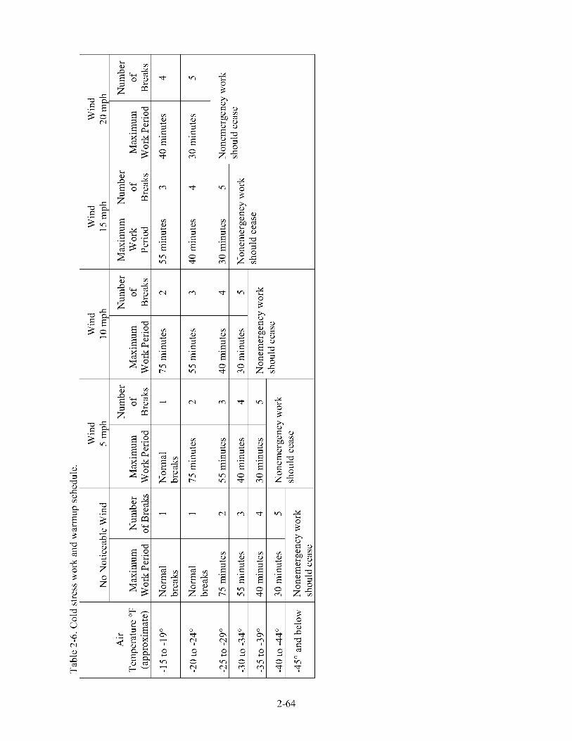
vi
I
I
I
rA b)
3 d
Y
T vi r-.
3 0 b) e a
i
9
7 0 vi
0 d
0
0
9
9 Y
2-64
2.4.5 Biological Hazards
The ICDF Complex is located in an area that provides habitat for various rodents, insects, and vectors (i.e., organisms that carry disease-causing microorganisms from one host to another). The potential exists for encountering nesting materials or other biological hazards and vectors. The hantavirus may be present in the nesting and fecal matter of deer mice. If such materials are disturbed, they can become airborne and create a potential inhalation pathway for the virus. Contact and improper removal of these materials may provide additional inhalation exposure risks.
If suspected rodent nesting or excrement material is encountered, the IH will be notified immediately and no attempt will be made to remove or clean the area. Following an evaluation of the area, disinfection and removal of such material will be conducted in accordance with applicable company policies and procedures.
Snakes, insects, and arachnids (e.g., spiders, ticks, and mosquitoes) also may be encountered at the ICDF. Common areas to avoid include material stacking and staging areas, under existing structures (e.g., trailers and buildings), under boxes, and other areas that provide shelter. Protective clothing will generally prevent insects from direct contact with the skin. If potentially dangerous snakes or spiders are found or are suspected of being present, warn others, keep clear and contact the IH or HSO for additional guidance as required.
Insect repellant (DEET or equivalent) may be required. Areas where standing water has accumulated (e.g., evaporation ponds) provide breeding grounds for mosquitoes and should be avoided. In cases where a large area of standing water is encountered, it may be necessary to pump the water out of the declivity (areas other than the evaporation ponds).
2.4.6 Inclement Weather Conditions
When inclement or adverse weather conditions develop that may pose a threat to persons or property at the ICDF area (such as sustained strong winds 25 mph or greater, electrical storms, heavy precipitation, or extreme heat or cold) these conditions will be evaluated and a decision made by the HSO, with input from the IH, safety engineer, RCT, and other personnel, as appropriate, to stop work, employ compensatory measures, or proceed. The field supervisor and HSO shall comply with company MCPs and facility work control documents that specify limits for inclement weather.
During all ICDF activities, the HSO, in consultation with the field supervisor, Radiological Control (RadCon) and IH personnel, will determine if wind or other weather conditions pose unacceptable hazards to personnel or the environment.
2.5 Other ICDF Hazards
ICDF personnel should continually look for potential hazards and immediately inform the field supervisor or HSO of the hazards so that action can be taken to correct the condition. All personnel have the authority to initiate STOP WORK actions in accordance with applicable company policies and procedures if it is perceived that an imminent safety of health hazard exists or take corrective actions within the scope of the work control authorization documents to correct minor safety of health hazards and then inform the field team leader (FTL).
Personnel working at the ICDF are responsible to use safe-work practices, report unsafe working conditions or acts, and exercise good housekeeping habits with respect to tools, equipment, and waste during ICDF operations.
2-65
2.6 Site Inspections
The HSO, RCT, and field supervisor may participate in ICDF site inspections during the work control preparation stage (such as the hazard identification and verification walkdowns), conduct self-assessments, or other inspections. Additionally, the HSO, project manager, or field supervisor, in accordance with applicable company policies and procedures, will perform periodic safety inspections.
Targeted or required self-assessments may be performed during ICDF operations in accordance with applicable company policies and procedures. All inspections and assessments will be documented and available for review by the field supervisor. The HSO or other health and safety professionals present at the ICDF may, at any time, recommend changes in work habits to the field supervisor. However, all changes that may affect the facility written work control documents (e.g., HASP, JSAs, RWPs, SWPs, work order) must have concurrence from the appropriate facility technical discipline representative onsite and a Document Action Request prepared to the applicable document as required.
2-66