industry standards-based solution for sap plant ... · pdf fileindustry standards-based...
TRANSCRIPT
© 2008 Eventure Events. All rights reserved.
Industry Standards-Based Solution for SAP Plant Maintenance (ISPM)
Tony Ciliberti, PE
Reliability Dynamics LLC
© 2008 Eventure Events. All rights reserved.
ISPM Overview
Key Learning Objectives
• The importance of industry standard integration with corporate information systems
• Key objectives for asset management
• Why a ‗reliability language‘ is imperative for communicating operational experience
• Common asset management issues
© 2008 Eventure Events. All rights reserved.
Mantra: If you can’t analyze 1000 things at once, you’re
not doing it right

Plant Maintenance Scope
Most Master Data Most Transactional Data
Risk Management
Design
inherently safe
and reliable
processes
Risk Assess-
ments
Process and
eqpt design data
Equipment capabilities data
Optimize decision-making with accessible high-quality information
Manage risk with preventive maintenance, spare parts, procedures, and other safeguards
Optimize resources
Prioritize activities based on loss potential
Planning and scheduling
As-built
Plant Maintenance

© 2008 Eventure Events. All rights reserved.
Key Objectives
Key Objectives for Enterprise Asset Management
• Maximize production output via increased equipment availability
• Minimize health, safety, and environmental incidents
• Optimize efficiency of resources

How to Achieve Key Objectives
• Make data-driven decisions
– Optimize decision making with accessible and high-quality information
• Use risk-based prioritization of programs and work
– Maximize benefit-to-cost
• Optimize work execution with planning and scheduling

The Importance of Information
• We require accurate and accessible information to make sound decisions about the operation of our facilities
– Better information means better decisions
– Better decisions mean more reliable and profitable operation and fewer hazards
• The key to better information is high quality data

Information Challenges
• We manage a ‗mountain‘ of information
– Tens of thousands to millions of equipment items and related process safety information
– Hundreds to thousands of transactions created and processed daily
• Data-driven decision-making is limited by time available to gather information
• Many different people with diverse backgrounds contributing to the data store
• Data are stored disparately and in a manner that does not facilitate analyses
© 2008 Eventure Events. All rights reserved.
Customer Issues

My Experience…
• Many implementations are ―new wheels‖ – Some use of ―best practices‖
• Implementation partner personnel typically: – Have never worked in industry as reliability engineers
– Have never used EAM solutions they developed in execution of their day-to-day engineering responsibilities
– Are unfamiliar with industry standards
• Customer SMEs on new implementations typically: – Have never used SAP in execution of their day-to-day engineering
responsibilities
– Do not fully understand SAP functionality and are unfamiliar with its nuances (typically gained by application of functionality).
• Result: disconnects and functionality gaps discovered after go-live
My First Corporate Roll-out…Not Atypical!
– Every location replicated existing facility-specific processes in SAP
– SAP was not the single source of master data
– No consistency between locations in technical object structuring
– Inconsistent and incomplete practices for failure coding; personnel reverted to using long text
– No provisions made for capturing inspection data as discrete values
– Poor work management practices resulting in improper cost allocation
– No document management strategy
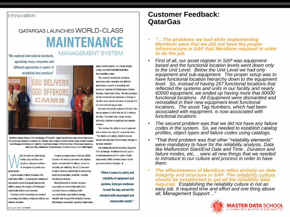
Customer Feedback: QatarGas
• “…The problems we had while implementing Meridium were that we did not have the proper infrastructure in SAP that Meridium required in order to do the job.
• First of all, our asset register in SAP was equipment-based and the functional location levels went down only to the Unit Level. Below the Unit Level we had only equipment and sub-equipment. The proper setup was to have functional location hierarchy down to the equipment level. So, instead of having 267 functional locations that reflected the systems and units in our facility and nearly 60000 equipment, we ended up having more that 60000 functional locations. All Equipment were dismantled and reinstalled in their new equipment level functional locations. The asset Tag Numbers, which had been associated with equipment, is now associated with functional locations
• The second problem was that we did not have any failure codes in the system. So, we needed to establish catalog profiles, object types and failure codes using catalogs.
• “That third problem was that other “reliability elements” were mandatory to have for the reliability analysis. Data like Malfunction Start/End Date and Time , Duration and failure modes, etc.. , were all new things that we needed to introduce to our culture and process in order to have them.
• The effectiveness of Meridium relies entirely on data integrity and structure in SAP. The reliability culture should be established to get all the reliability data required. Establishing the reliability culture in not an easy job. It required time and effort and one thing above all, Management Support…”
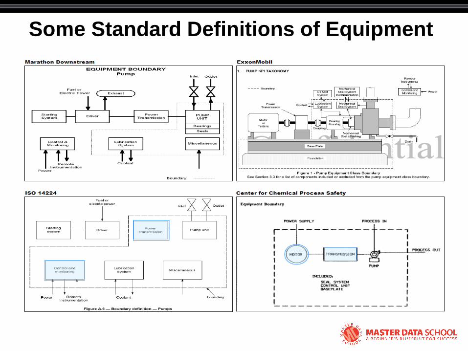
Some Standard Definitions of Equipment
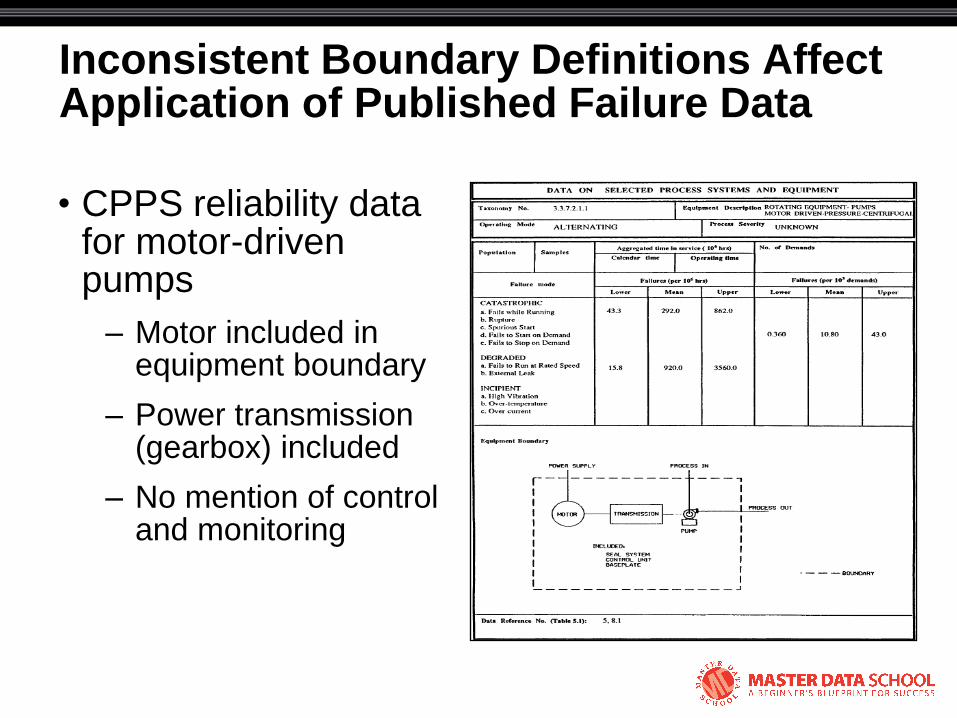
Inconsistent Boundary Definitions Affect Application of Published Failure Data
• CPPS reliability data for motor-driven pumps
– Motor included in equipment boundary
– Power transmission (gearbox) included
– No mention of control and monitoring
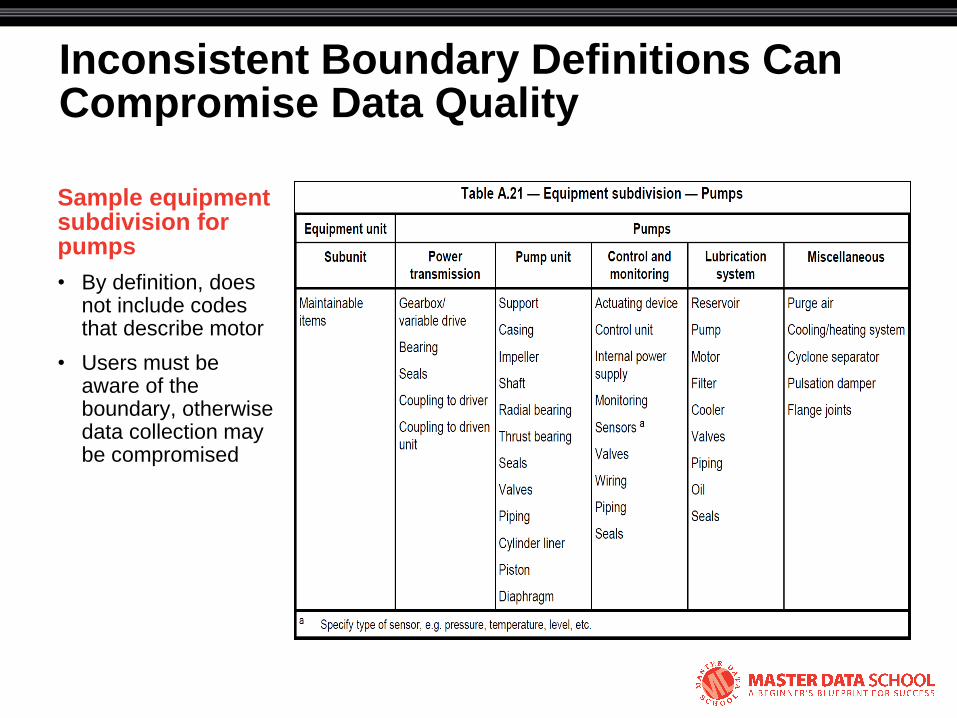
Inconsistent Boundary Definitions Can Compromise Data Quality
Sample equipment subdivision for pumps
• By definition, does not include codes that describe motor
• Users must be aware of the boundary, otherwise data collection may be compromised
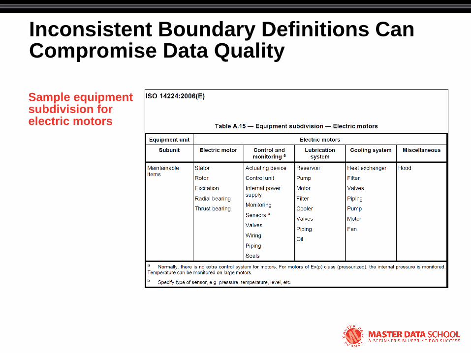
Inconsistent Boundary Definitions Can Compromise Data Quality
Sample equipment subdivision for electric motors
Other Data Quality Issues that Affect Metrics
• Work executed on blanket orders
• Use of stockpiled spare parts instead of booking materials to repair orders
• Multiple work orders/notifications for the same repair
• Timing of work orders/notifications
• Inconsistent practices for booking repair time against work orders
• Inconsistent treatment/allocation of overhead costs
Data Access Issues
• Data stored in a non-structured manner
– Scanned Images
– Free-form text
• Disparate data
– Disparate stand-alone applications
– Suppliers data repositories
– Access databases and Excel spreadsheets
Data Access Issues
• Reasons for disparate data repositories
– Specialized functionality that will never be part of the maintenance system, e.g. vibration spectra
– Configuration of the maintenance system makes it difficult to input and/or extract discrete inspection data
– Unwillingness of personnel to turn-over data to the maintenance system
• Issues
– Repositories are typically available only to the specific site where they are maintained
– Merging data is much more difficult

The Solution
• Use standard ―..data collection principles and associated terms and definitions that constitute a ‗reliability language‘…for communicating operational experience‖
• Develop a hierarchical framework (taxonomy) for equipment to make data readily accessible, retrievable, and comparable between similar technical objects and process applications
• Capture data in a manner that facilitates analyses
– Use discrete values versus scanned images and free text
• Cockpit view: give users a single point of entry to all information
© 2008 Eventure Events. All rights reserved.
Industry Standards

Some Reasons Why Standardization is Important for Asset Management
• Engineering practice
– Solutions should follow recognized and generally accepted good engineering practices (RAGAGEP)
– Common terms and definitions are imperative to communicate failure details
– Standard reliability data allows companies and manufacturers to learn from other‘s experiences
• Solution
– Ensure capabilities of ERP systems are properly and fully exploited by SAP customers
– Ensure that solutions implemented are tried and tested methods proven by actual practice
– Streamline and reduce deployment costs

Examples of Commonly-used Industry Standards
• ISO 14224: Petroleum, petrochemical and natural gas industries — Collection and exchange of reliability and maintenance data for equipment
• ISO 15926-2: Industrial automation systems and integration -- Integration of life-cycle data for process plants including oil and gas production facilities -- Part 2: Data model
• Norsok Z-002-DP: Design Principles Coding System
• API RP 579: Fitness for Service
• API RP 580: Risk-based Inspection
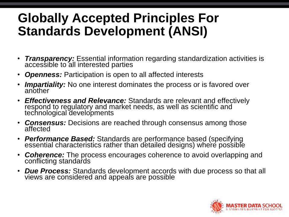
Globally Accepted Principles For Standards Development (ANSI)
• Transparency: Essential information regarding standardization activities is accessible to all interested parties
• Openness: Participation is open to all affected interests
• Impartiality: No one interest dominates the process or is favored over another
• Effectiveness and Relevance: Standards are relevant and effectively respond to regulatory and market needs, as well as scientific and technological developments
• Consensus: Decisions are reached through consensus among those affected
• Performance Based: Standards are performance based (specifying essential characteristics rather than detailed designs) where possible
• Coherence: The process encourages coherence to avoid overlapping and conflicting standards
• Due Process: Standards development accords with due process so that all views are considered and appeals are possible
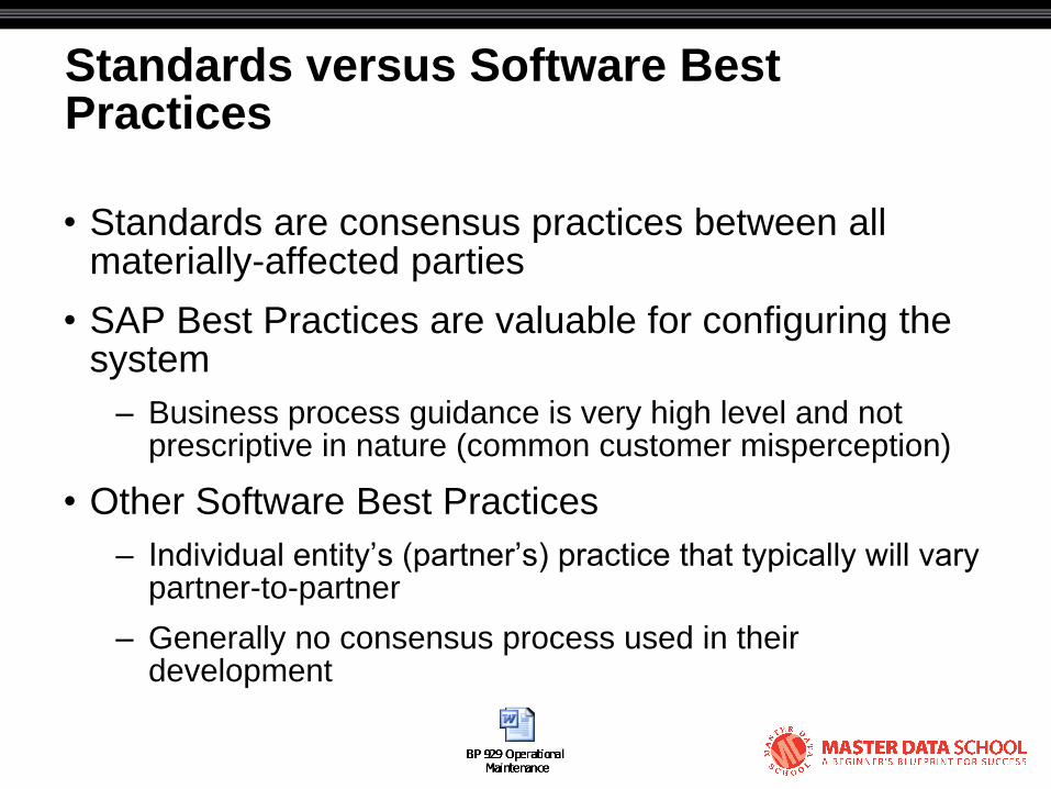
Standards versus Software Best Practices
• Standards are consensus practices between all materially-affected parties
• SAP Best Practices are valuable for configuring the system
– Business process guidance is very high level and not prescriptive in nature (common customer misperception)
• Other Software Best Practices
– Individual entity‘s (partner‘s) practice that typically will vary partner-to-partner
– Generally no consensus process used in their development

OREDA Example

OREDA Example

The OG&P Standards Vision
• The intent/purpose of ISO 14224/OREDA is to develop a reliability language BETWEEN companies in the oil and gas industry sector, not just within companies
– Facilitates merging and analysis of data
– OREDA (OFFshore REliability DAtabase) is the platform
• Each company independently changing the standard defeats this intent

© 2008 Eventure Events. All rights reserved.
ISPM Equipment Reliability Data
Key Learning Objectives
• Primary building blocks of a reliability data infrastructure
• The ISO 14224-compliant equipment failure data collection process in SAP
• Use of operating context to classify failure data for reporting purposes
© 2008 Eventure Events. All rights reserved.
We need “..data collection principles and associated terms and definitions that constitute a
„reliability language‟…for communicating operational experience.”
— ISO 14224: 2006
Compliancy with Industry Standards
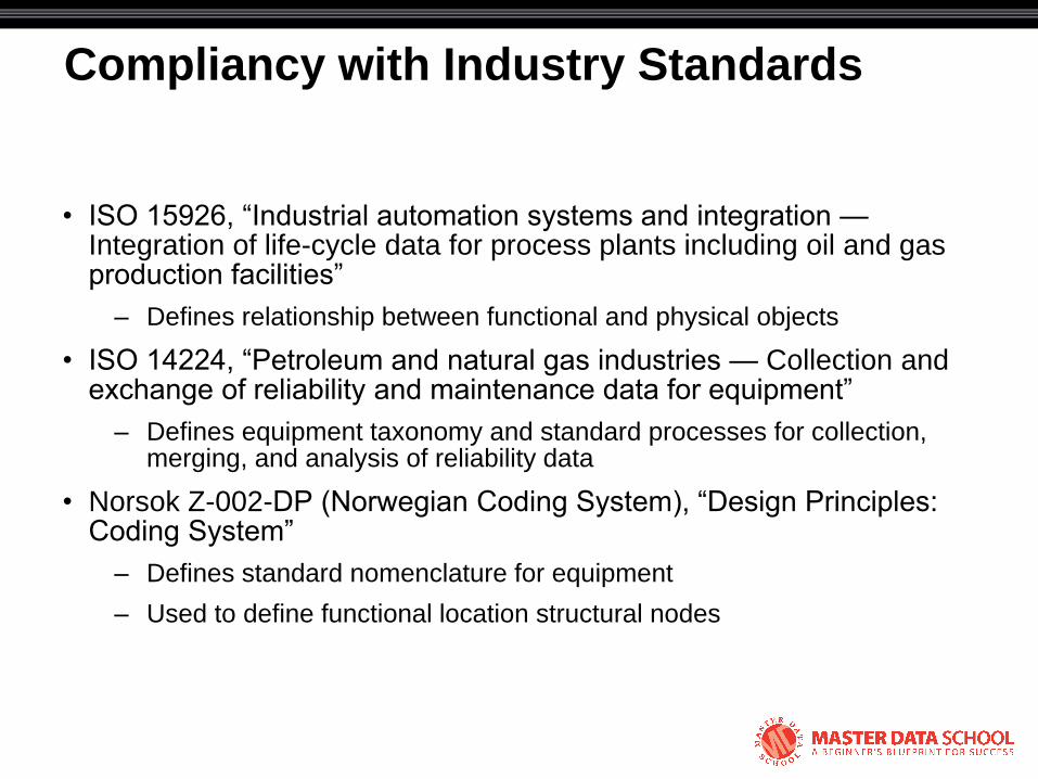
• ISO 15926, ―Industrial automation systems and integration — Integration of life-cycle data for process plants including oil and gas production facilities‖
– Defines relationship between functional and physical objects
• ISO 14224, ―Petroleum and natural gas industries — Collection and exchange of reliability and maintenance data for equipment‖
– Defines equipment taxonomy and standard processes for collection, merging, and analysis of reliability data
• Norsok Z-002-DP (Norwegian Coding System), ―Design Principles: Coding System‖
– Defines standard nomenclature for equipment
– Used to define functional location structural nodes
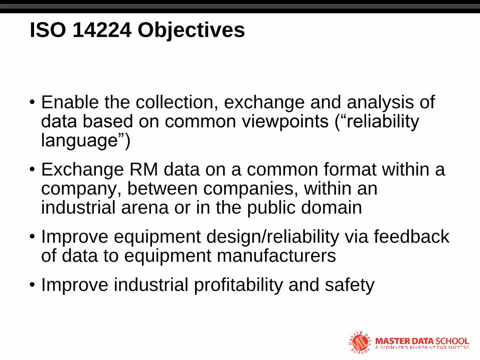
ISO 14224 Objectives
• Enable the collection, exchange and analysis of data based on common viewpoints (―reliability language‖)
• Exchange RM data on a common format within a company, between companies, within an industrial arena or in the public domain
• Improve equipment design/reliability via feedback of data to equipment manufacturers
• Improve industrial profitability and safety
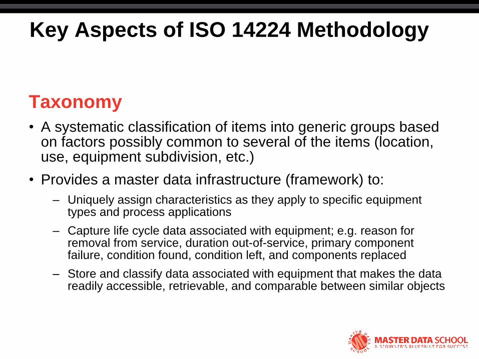
Key Aspects of ISO 14224 Methodology
Taxonomy
• A systematic classification of items into generic groups based on factors possibly common to several of the items (location, use, equipment subdivision, etc.)
• Provides a master data infrastructure (framework) to:
– Uniquely assign characteristics as they apply to specific equipment types and process applications
– Capture life cycle data associated with equipment; e.g. reason for removal from service, duration out-of-service, primary component failure, condition found, condition left, and components replaced
– Store and classify data associated with equipment that makes the data readily accessible, retrievable, and comparable between similar objects

Key Aspects of ISO 14224 Methodology
Standard processes for failure data collection
• Equipment class boundary definitions
• Failure and activity codes
• Time definitions
• Consequence severity assessment
• KPIs and benchmarking

SAP Master Data
• Technical Objects
– Functional locations
– Equipment
• Catalogs
• Class and characteristics
• Measuring points/counters
• Document information records
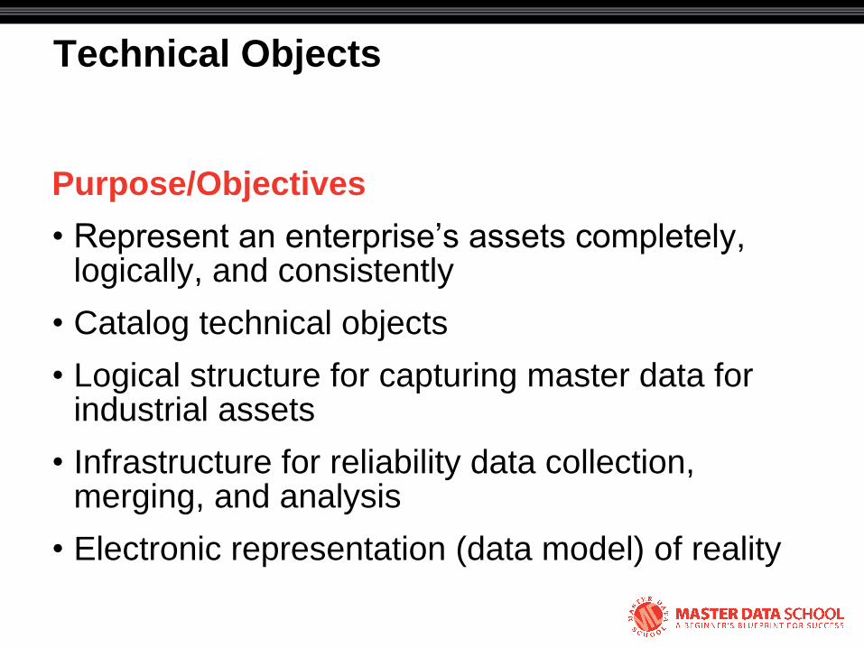
Technical Objects
Purpose/Objectives
• Represent an enterprise‘s assets completely, logically, and consistently
• Catalog technical objects
• Logical structure for capturing master data for industrial assets
• Infrastructure for reliability data collection, merging, and analysis
• Electronic representation (data model) of reality

Technical Objects Considerations
• Should be designed in accordance with applicable industry and company standards
• Design should be systematic and consistent for uniformity across a broad industrial spectrum
– Flexible structures to accommodate both simple and complex facilities
• Should be designed for ease of recordkeeping
Functional Location Objects
• Intangible objects that describe process requirements
• Roll-up points for costs, reliability data, or any other data
• Structured hierarchically
• Functional Area Location (FAL)
– Grouping location: no equipment installation
• Functional Equipment Location (FEL)
– Equipment installation point
– Carries P&ID tag number

Equipment Objects
• Tangible objects, most with serial numbers
• Typically begin as material masters
– Material + serial number = equipment
• Capabilities must meet or exceed requirements at FEL installation point
– FEL-to-primary equipment cardinality should be 1:1
• Every equipment item should belong to a standard equipment class
• Every equipment class should have failure codes per industry standard ISO 14224 or equivalent company standard

© 2008 Eventure Events. All rights reserved.
Coincident Individuals
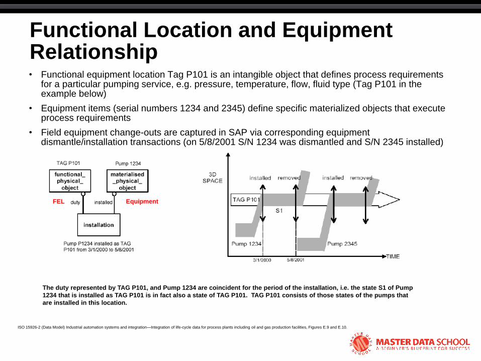
Functional Location and Equipment Relationship • Functional equipment location Tag P101 is an intangible object that defines process requirements
for a particular pumping service, e.g. pressure, temperature, flow, fluid type (Tag P101 in the example below)
• Equipment items (serial numbers 1234 and 2345) define specific materialized objects that execute process requirements
• Field equipment change-outs are captured in SAP via corresponding equipment dismantle/installation transactions (on 5/8/2001 S/N 1234 was dismantled and S/N 2345 installed)
ISO 15926-2 (Data Model) Industrial automation systems and integration—Integration of life-cycle data for process plants including oil and gas production facilities, Figures E.9 and E.10.
The duty represented by TAG P101, and Pump 1234 are coincident for the period of the installation, i.e. the state S1 of Pump
1234 that is installed as TAG P101 is in fact also a state of TAG P101. TAG P101 consists of those states of the pumps that
are installed in this location.
FEL Equipment
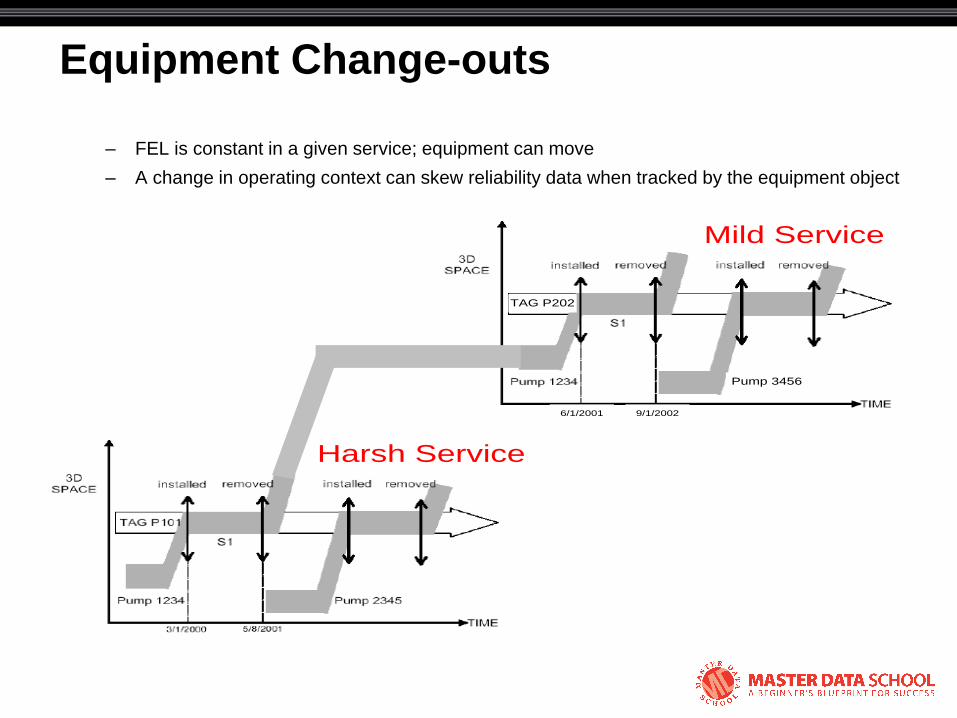
Equipment Change-outs
– FEL is constant in a given service; equipment can move
– A change in operating context can skew reliability data when tracked by the equipment object
6/1/2001 9/1/2002
Pump 3456
Mild Service
Harsh Service
TAG P202

Coincident Individuals
FEL
Equipment
FEL
Equipment
Capabilities of installed materialized physical
object (Equipment) must meet or exceed
requirements of functional physical object (FEL)

© 2008 Eventure Events. All rights reserved.
Functional Location Hierarchy
Functional Location Hierarchy Design Guidance
• Use a standard process for generating tag numbers (e.g. NORSOK Z-002-DP)
• Use the tagging standard to help define the hierarchy
• Differentiate tags at different facilities with a prefix, e.g. XXYY-[tag no]
– Country code: XX
– Installation code: YY
• The four-digit code is a logical choice for the maintenance plant ID

Functional Location Hierarchy Design Guidance
• Use a multi-template design
– Template 1 = enterprise
– Template 2 = installation grouping levels (FAL)
– Template 3 = equipment (FEL) and sub-equipment (SFEL)
• Use a dynamic structure with optional nodes to accommodate different levels of complexity
– Use functional location categories to identify each level

FL Hierarchy Design per NORSOK Z-002-DP Standard

FL Hierarchy Design per NORSOK Z-002-DP Standard
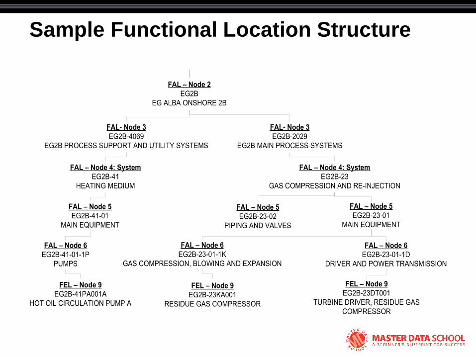
Sample Functional Location Structure
FAL – Node 2
EG2B
EG ALBA ONSHORE 2B
FAL- Node 3
EG2B-2029
EG2B MAIN PROCESS SYSTEMS
FAL – Node 4: System
EG2B-23
GAS COMPRESSION AND RE-INJECTION
FAL- Node 3
EG2B-4069
EG2B PROCESS SUPPORT AND UTILITY SYSTEMS
FAL – Node 4: System
EG2B-41
HEATING MEDIUM
FAL – Node 5
EG2B-41-01
MAIN EQUIPMENT
FAL – Node 5
EG2B-23-02
PIPING AND VALVES
FAL – Node 5
EG2B-23-01
MAIN EQUIPMENT
FAL – Node 6
EG2B-23-01-1D
DRIVER AND POWER TRANSMISSION
FEL – Node 9
EG2B-23DT001
TURBINE DRIVER, RESIDUE GAS
COMPRESSOR
FAL – Node 6
EG2B-23-01-1K
GAS COMPRESSION, BLOWING AND EXPANSION
FEL – Node 9
EG2B-23KA001
RESIDUE GAS COMPRESSOR
FAL – Node 6
EG2B-41-01-1P
PUMPS
FEL – Node 9
EG2B-41PA001A
HOT OIL CIRCULATION PUMP A
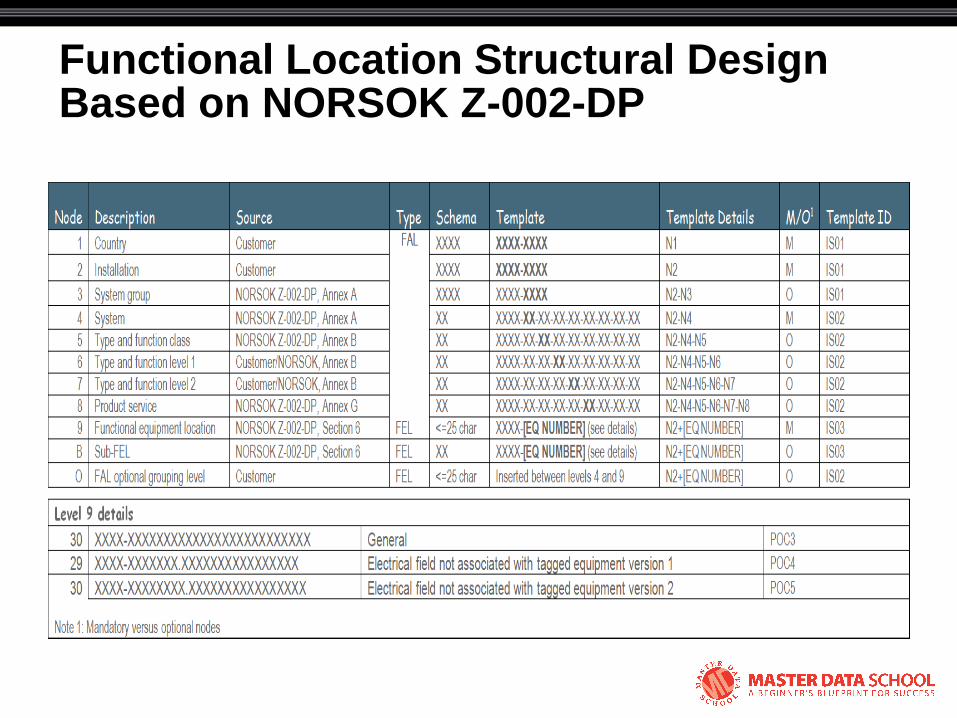
Functional Location Structural Design Based on NORSOK Z-002-DP

Sample Functional location structural design
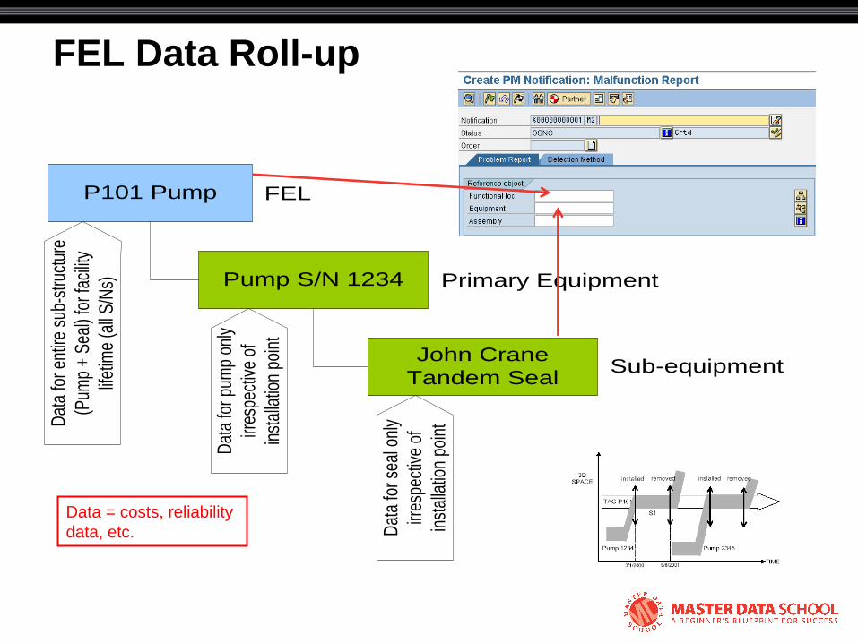
FEL Data Roll-up
P101 Pump
Pump S/N 1234
John Crane
Tandem Seal
FEL
Primary Equipment
Sub-equipment
Dat
a fo
r pum
p on
ly
irres
pect
ive
of
inst
alla
tion
poin
t
Dat
a fo
r sea
l onl
y
irres
pect
ive
of
inst
alla
tion
poin
tDat
a fo
r ent
ire s
ub-s
truct
ure
(Pum
p +
Sea
l) fo
r fac
ility
lifet
ime
(all
S/N
s)
Data = costs, reliability
data, etc.
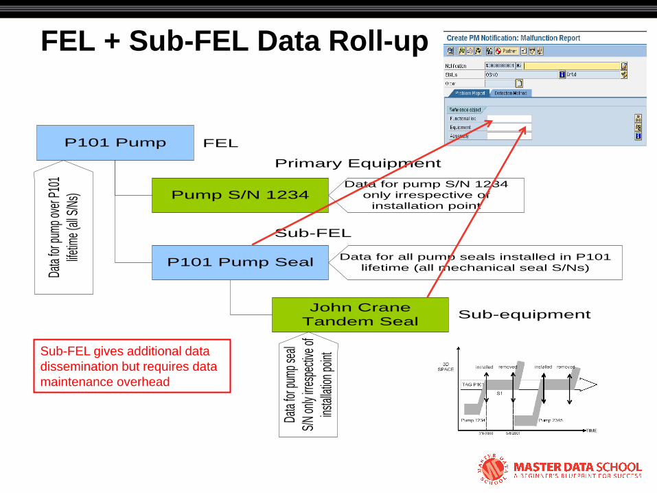
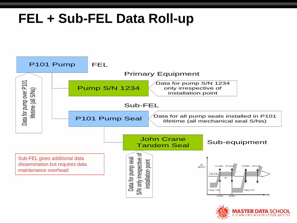
FEL + Sub-FEL Data Roll-up
P101 Pump
Pump S/N 1234
John Crane
Tandem Seal
FEL
Primary Equipment
Sub-equipment
Data for pump S/N 1234
only irrespective of
installation point
Data
for p
ump
seal
S/N
only
irres
pecti
ve o
f
insta
llatio
n po
int
Data
for p
ump
over
P10
1
lifetim
e (a
ll S/N
s)
P101 Pump Seal
Sub-FEL
Data for all pump seals installed in P101
lifetime (all mechanical seal S/Ns)
Sub-FEL gives additional data
dissemination but requires data
maintenance overhead
© 2008 Eventure Events. All rights reserved.
Equipment Subdivision and Catalogs

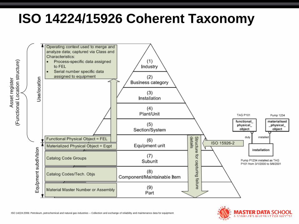
ISO 14224/15926 Coherent Taxonomy A
sse
t re
gis
ter
(Fu
nctio
na
l L
oca
tio
n s
tru
ctu
re)
ISO 14224:2006: Petroleum, petrochemical and natural gas industries -- Collection and exchange of reliability and maintenance data for equipment
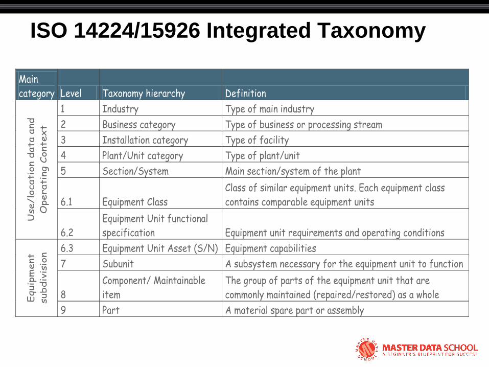
ISO 14224/15926 Integrated Taxonomy
Main
category Level Taxonomy hierarchy Definition
1 Industry Type of main industry
2 Business category Type of business or processing stream
3 Installation category Type of facility
4 Plant/Unit category Type of plant/unit
5 Section/System Main section/system of the plant
6.1 Equipment Class
Class of similar equipment units. Each equipment class
contains comparable equipment units
Use/lo
cati
on d
ata
and
Operati
ng C
onte
xt
6.2
Equipment Unit functional
specification Equipment unit requirements and operating conditions
6.3 Equipment Unit Asset (S/N) Equipment capabilities
7 Subunit A subsystem necessary for the equipment unit to function
8
Component/ Maintainable
item
The group of parts of the equipment unit that are
commonly maintained (repaired/restored) as a whole Equip
ment
subdiv
isio
n
9 Part A material spare part or assembly

Gas Turbine Equipment Class Boundary Definition
• Establishes consistency in definition of equipment units
– Facilitates ―apples-to-apples‖ data analysis
– Includes subunits and maintainable items
• SAP catalog functionality used for boundary definitions
– Catalog profile = boundary definition
– Catalog group = subunit
– Catalog code = maintainable item/component
Boundary definition
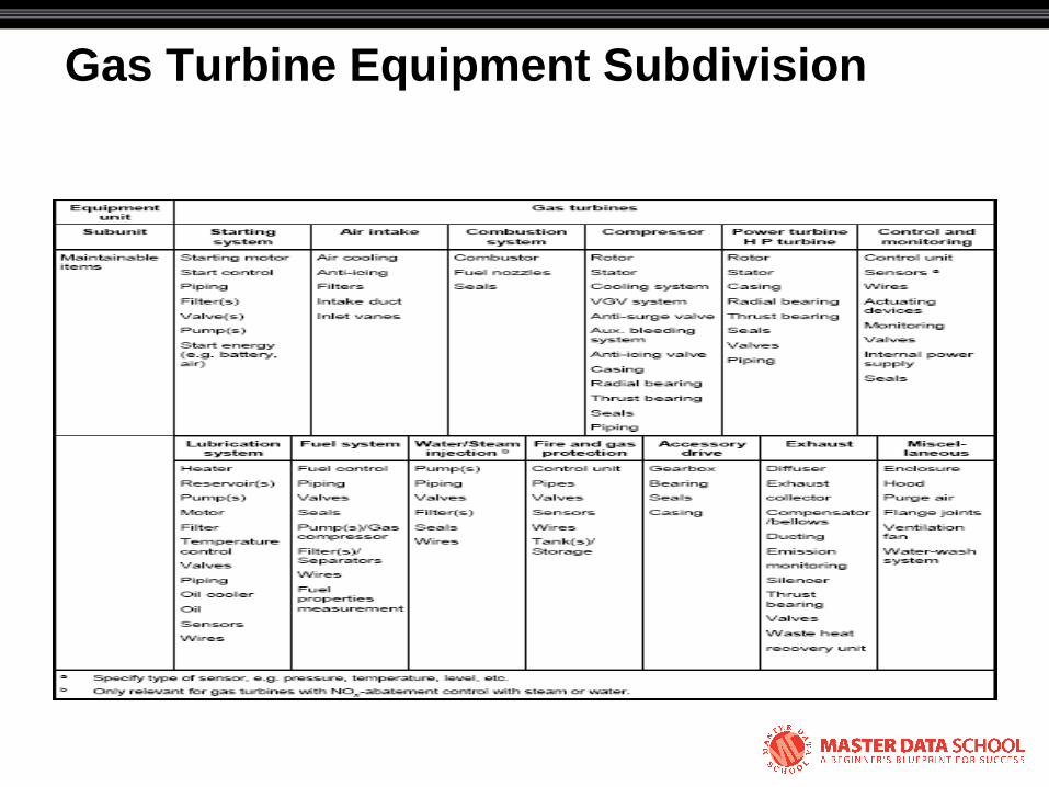
Gas Turbine Equipment Subdivision
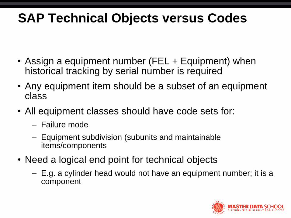
SAP Technical Objects versus Codes
• Assign a equipment number (FEL + Equipment) when historical tracking by serial number is required
• Any equipment item should be a subset of an equipment class
• All equipment classes should have code sets for:
– Failure mode
– Equipment subdivision (subunits and maintainable items/components
• Need a logical end point for technical objects
– E.g. a cylinder head would not have an equipment number; it is a component
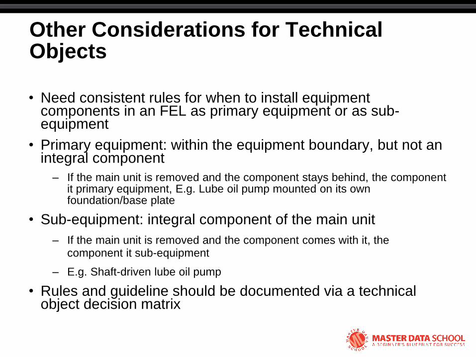
Other Considerations for Technical Objects
• Need consistent rules for when to install equipment components in an FEL as primary equipment or as sub-equipment
• Primary equipment: within the equipment boundary, but not an integral component
– If the main unit is removed and the component stays behind, the component it primary equipment, E.g. Lube oil pump mounted on its own foundation/base plate
• Sub-equipment: integral component of the main unit
– If the main unit is removed and the component comes with it, the component it sub-equipment
– E.g. Shaft-driven lube oil pump
• Rules and guideline should be documented via a technical object decision matrix
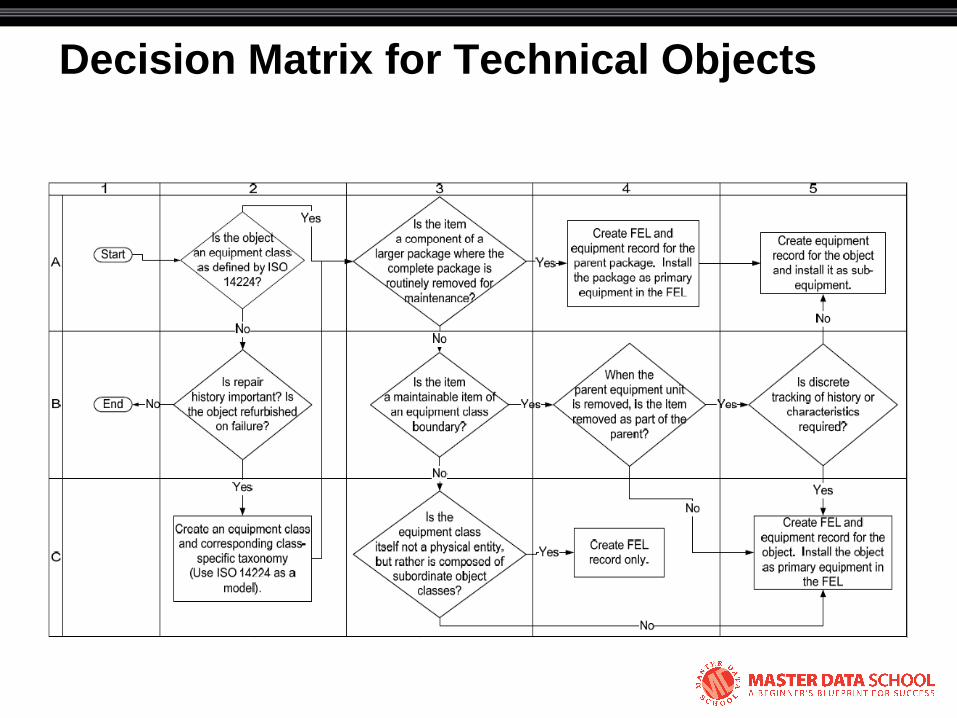
Decision Matrix for Technical Objects

© 2008 Eventure Events. All rights reserved.
Technical Object Classification
ISO 14224/15926 Coherent Taxonomy A
sse
t re
gis
ter
(Fu
nctio
na
l L
oca
tio
n s
tru
ctu
re)
ISO 14224:2006: Petroleum, petrochemical and natural gas industries -- Collection and exchange of reliability and maintenance data for equipment
Technical Object Classification and Characteristics
• Structure for capturing equipment master data
– Engineering design specifications/requirements
– Equipment capabilities
• Verification of equipment capabilities versus functional requirements
• Classification of equipment for data analysis purposes
SAP Class Structure
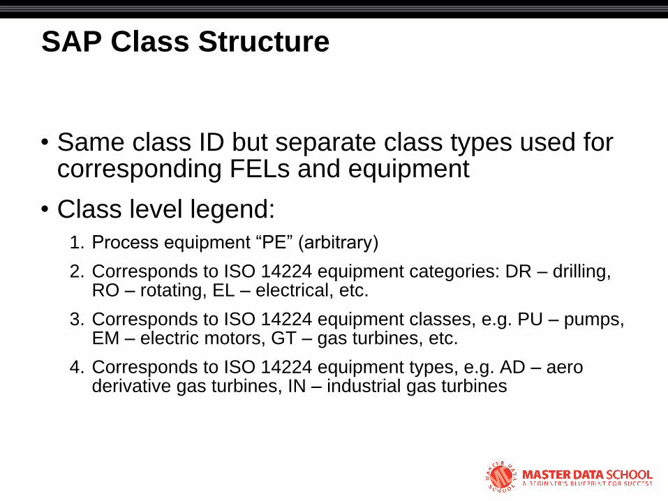
• Same class ID but separate class types used for corresponding FELs and equipment
• Class level legend:
1. Process equipment ―PE‖ (arbitrary)
2. Corresponds to ISO 14224 equipment categories: DR – drilling, RO – rotating, EL – electrical, etc.
3. Corresponds to ISO 14224 equipment classes, e.g. PU – pumps, EM – electric motors, GT – gas turbines, etc.
4. Corresponds to ISO 14224 equipment types, e.g. AD – aero derivative gas turbines, IN – industrial gas turbines
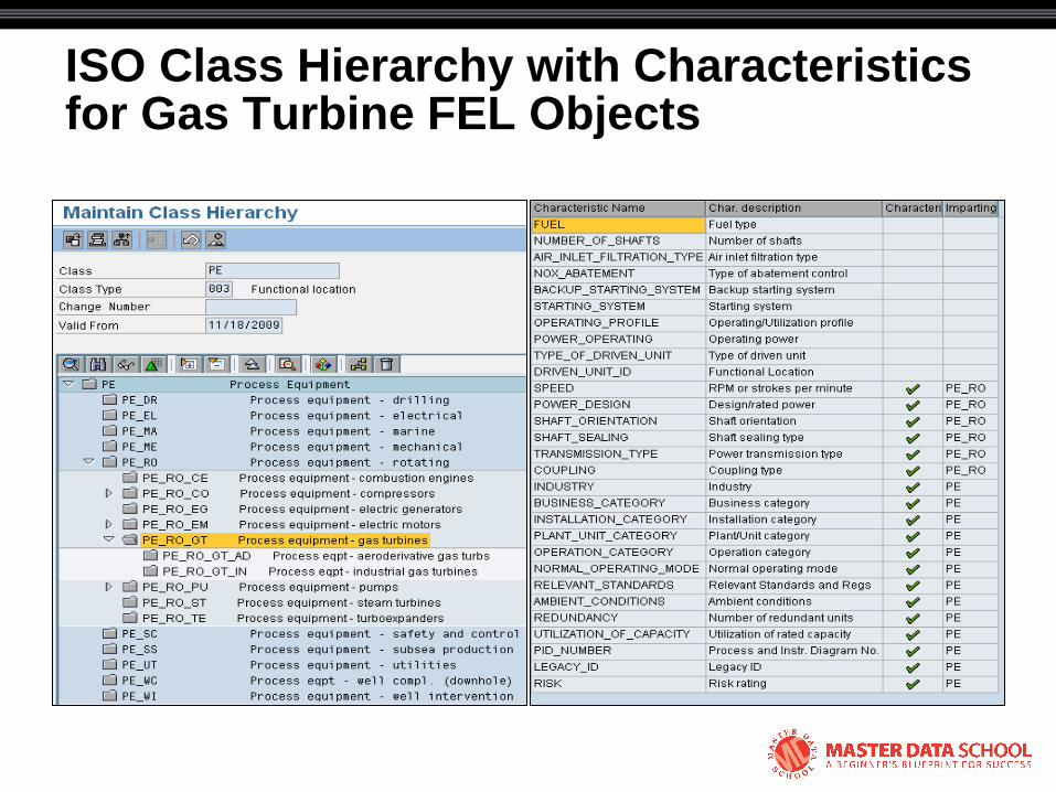
ISO Class Hierarchy with Characteristics for Gas Turbine FEL Objects
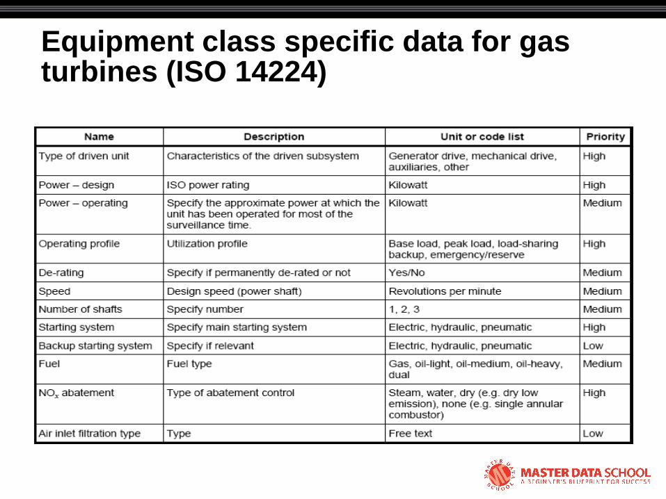
Equipment class specific data for gas turbines (ISO 14224)
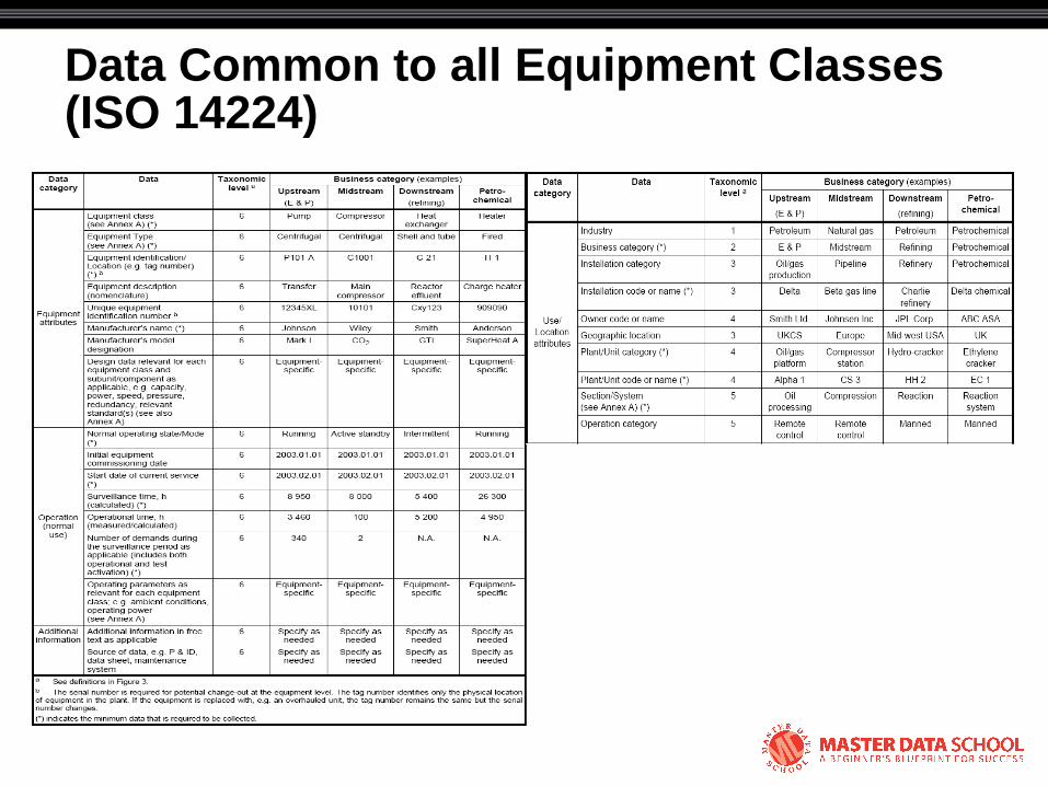
Data Common to all Equipment Classes (ISO 14224)
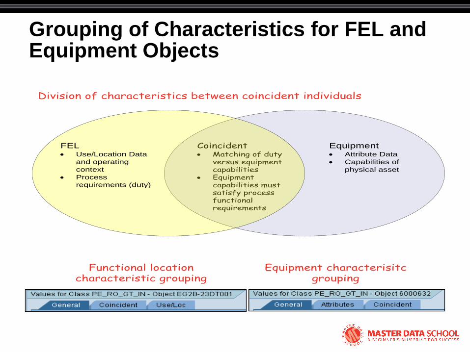
Grouping of Characteristics for FEL and Equipment Objects
Functional location characteristic grouping
Equipment characterisitc grouping
Coincident· Matching of duty
versus equipment capabilities
· Equipment capabilities must satisfy process functional requirements
Equipment· Attribute Data
· Capabilities of
physical asset
FEL· Use/Location Data
and operating
context
· Process
requirements (duty)
Division of characteristics between coincident individuals
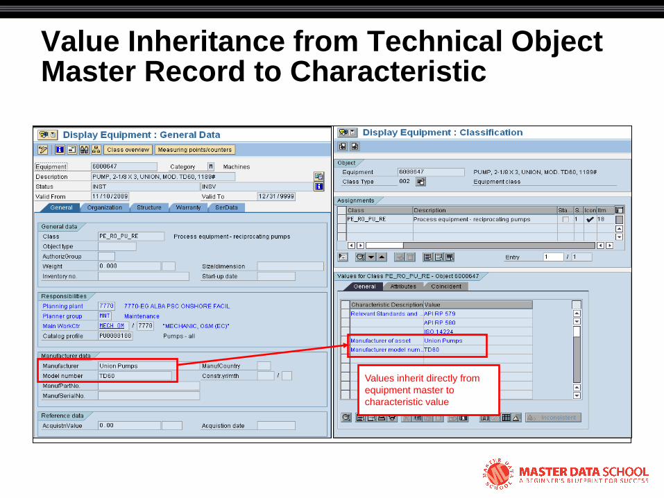
Value Inheritance from Technical Object Master Record to Characteristic
Values inherit directly from
equipment master to
characteristic value

Risk-rating for Equipment (FEL) via Class and Characteristics Functionality
ISO 14224 matrix accessed
directly from characteristic via
DIR record (DMS functionality)
Consequence severity (CS) matched
with likelihood (L) to give risk levels
– one or more CSL pairs possible
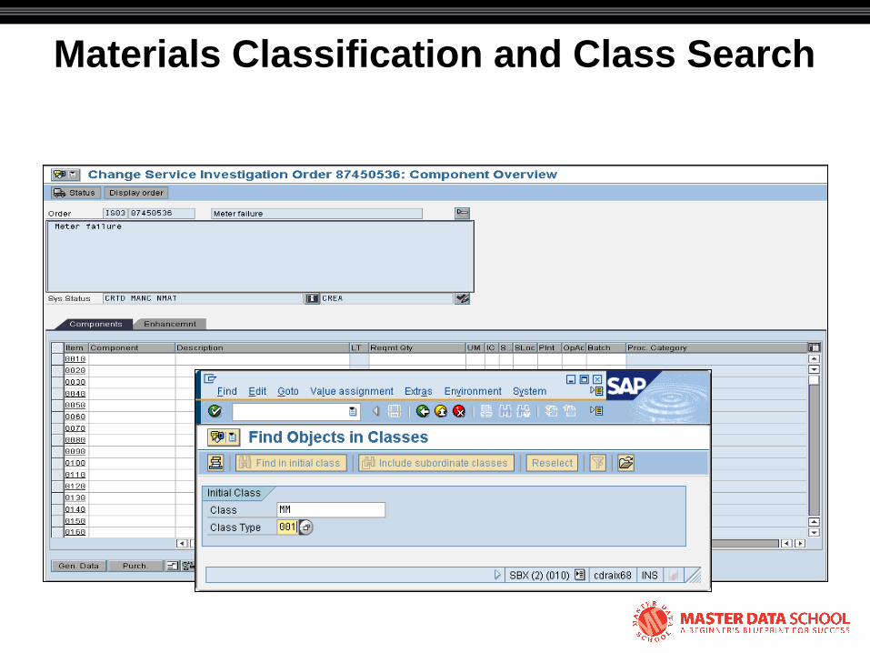
Materials Classification and Class Search
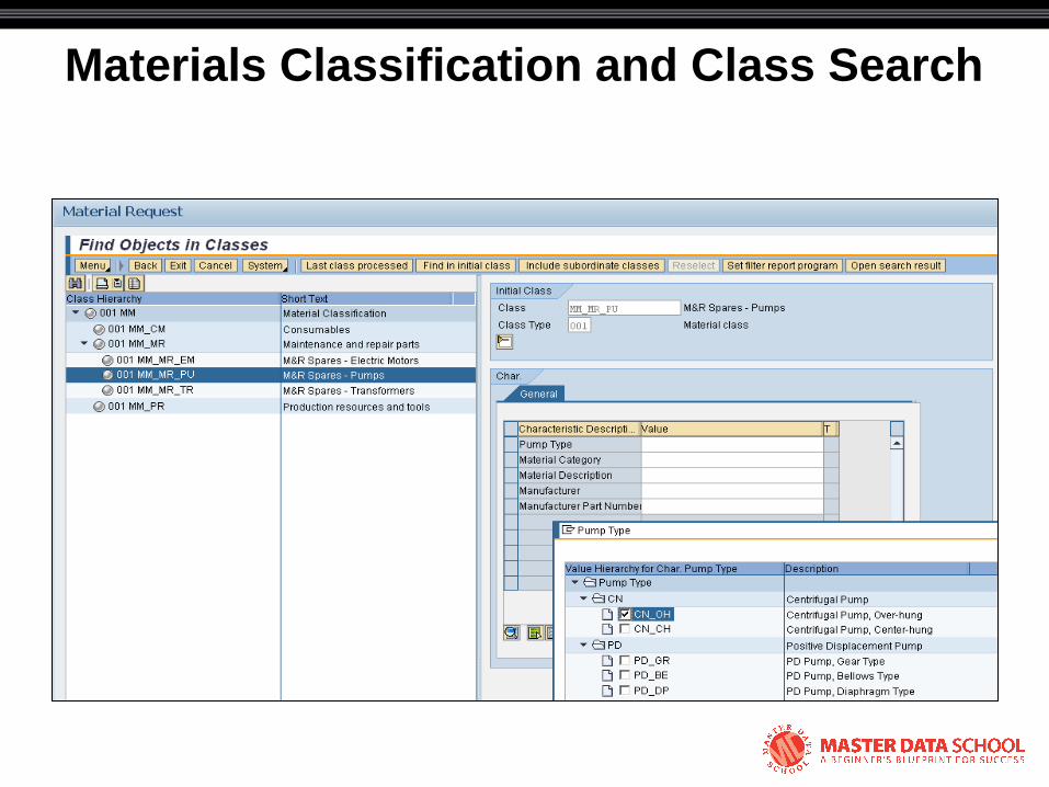
Materials Classification and Class Search
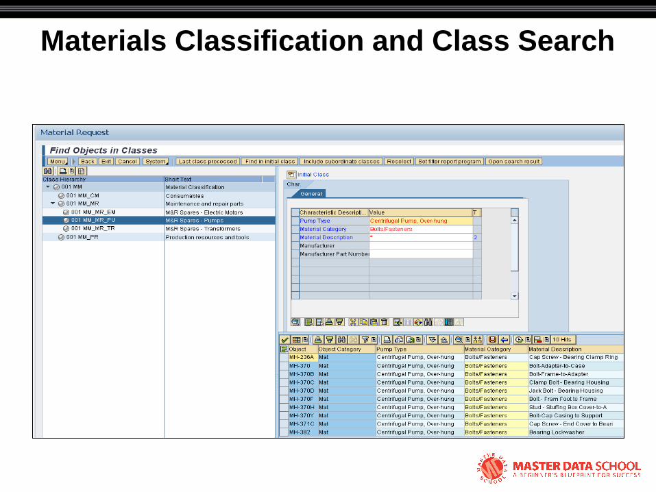
Materials Classification and Class Search
© 2008 Eventure Events. All rights reserved.
Malfunction Reports: SAP Compliance with ISO 14224

Malfunction Report as Subset of the Complete Order Process
1. Equipment malfunction
3. Generate Malfunction Report”IW24
4. Notification approval and
releaseIW28
5. Order released from notification
IW22/IW28
6. Order planningIW32
7. Assignment of work clearance requirements
2. Use functional location
structural display to select equipment
IH01
10. Schedule resources and
work
9. Release orderIW32/IW38
8. Dependency checks(IW32)
11. Print shop papers and
attachmentsIW37N
15. Technical completion
IW32
14. Work confirmations and
Complete Malfunction
ReportIW41/IW42
13. Ad-hoc parts requirements
MB1A
12. Execute work
16. SettlementKO88 (Batch)
17. Business Close Order (IW32
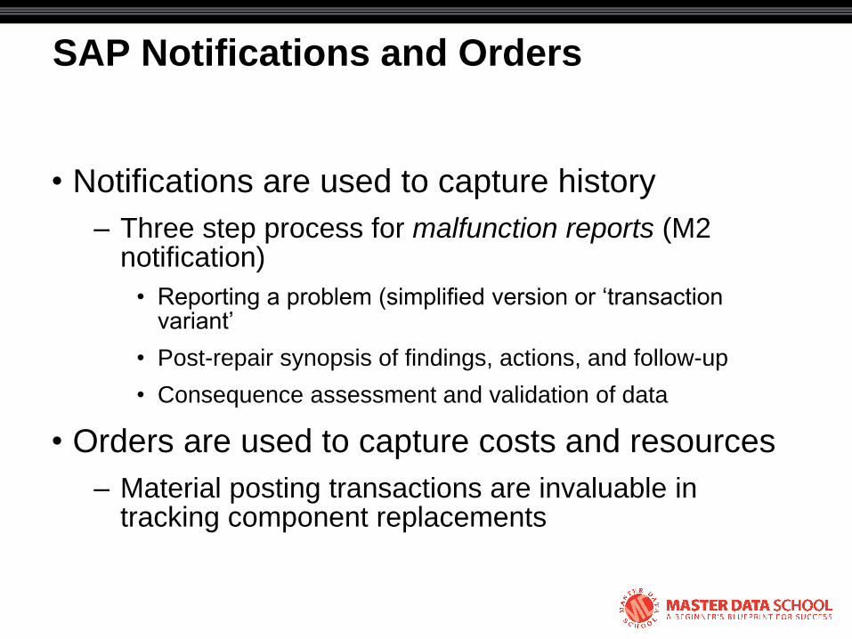
SAP Notifications and Orders
• Notifications are used to capture history
– Three step process for malfunction reports (M2 notification)
• Reporting a problem (simplified version or ‗transaction variant‘
• Post-repair synopsis of findings, actions, and follow-up
• Consequence assessment and validation of data
• Orders are used to capture costs and resources
– Material posting transactions are invaluable in tracking component replacements
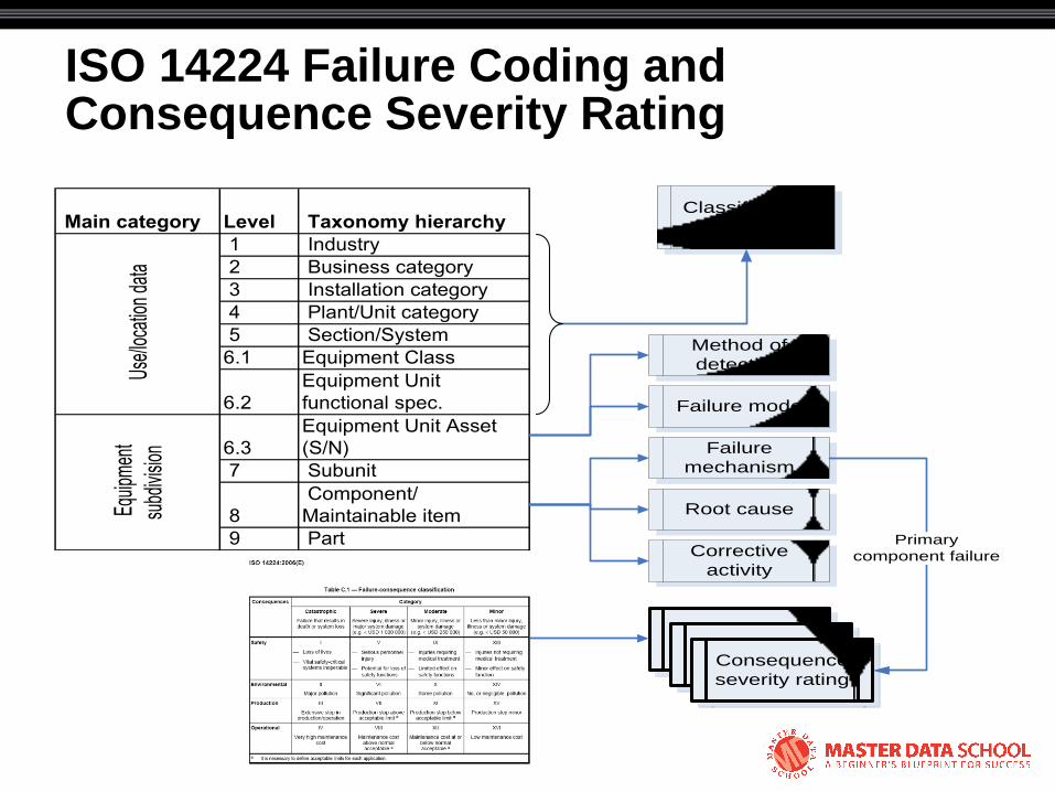
ISO 14224 Failure Coding and Consequence Severity Rating
Main category Level Taxonomy hierarchy
1 Industry
2 Business category
3 Installation category
4 Plant/Unit category
5 Section/System
6.1 Equipment Class
6.2
Equipment Unit
functional spec.
6.3
Equipment Unit Asset
(S/N)
7 Subunit
8
Component/
Maintainable item
9 Part
Use
/loca
tion
data
E
quip
men
t
subd
ivisio
n
Method of
detection
Failure
mechanism
Classification
of failure data
Consequence/
Likelihood
Primary
component failure
Consequence/
LikelihoodConsequence
severity rating
Failure mode
Root cause
Corrective
activity
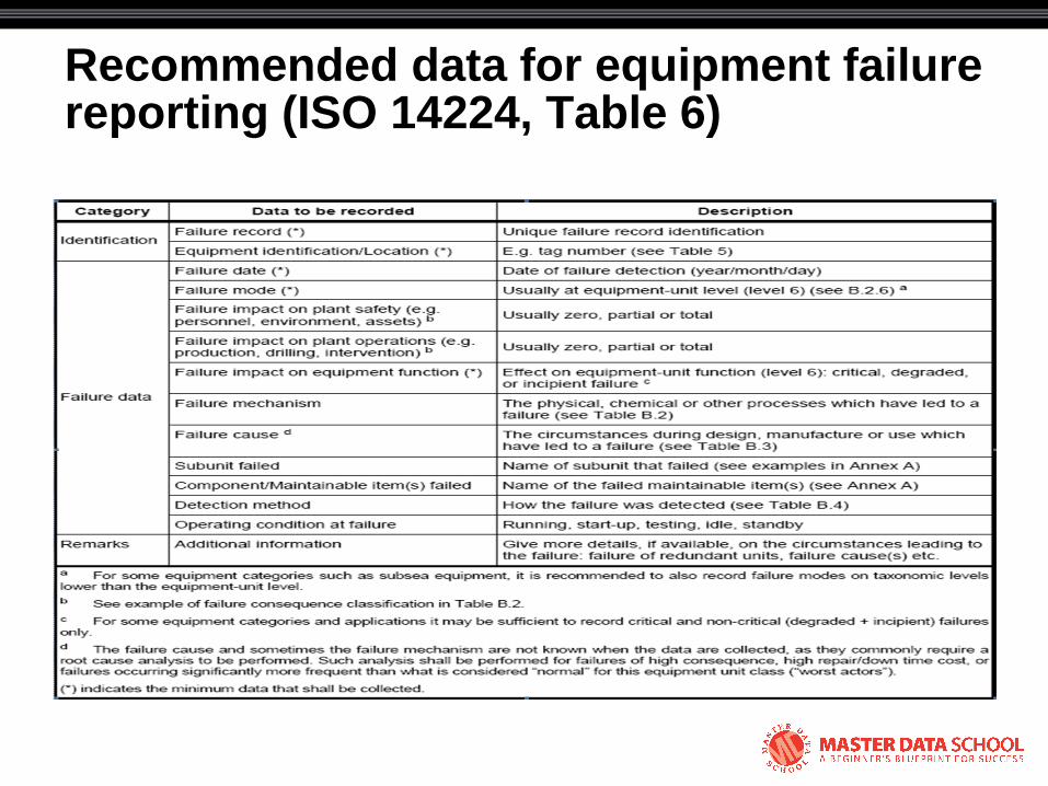
Recommended data for equipment failure reporting (ISO 14224, Table 6)
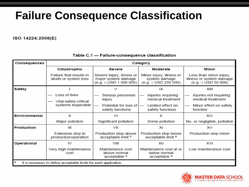
Failure Consequence Classification
FEL + Sub-FEL Data Roll-up
P101 Pump
Pump S/N 1234
John Crane
Tandem Seal
FEL
Primary Equipment
Sub-equipment
Data for pump S/N 1234
only irrespective of
installation point
Data
for p
ump
seal
S/N
only
irres
pecti
ve o
f
insta
llatio
n po
int
Data
for p
ump
over
P10
1
lifetim
e (a
ll S/N
s)
P101 Pump Seal
Sub-FEL
Data for all pump seals installed in P101
lifetime (all mechanical seal S/Ns)
Sub-FEL gives additional data
dissemination but requires data
maintenance overhead

Multi-level malfunction reporting process

Progressive Level of Detail

Malfunction Problem Report
Equipment level assessment
• Failure mode (class specific)
– Equipment-level symptom or observed failure
• Method of detection
– Equipment-level method or activity by which a failure is discovered
– Vitally important to distinguish between failures discovered by either:
• A planned action (inspection, PM maintenance, audit)
• By chance (casual observation)

Malfunction Problem Report
Equipment level assessment
• Malfunction start date/time
• Effect on system
– Critical failure
– Degraded function
– Incipient failure
• Equipment condition at start-up
• Work priority and administrative data
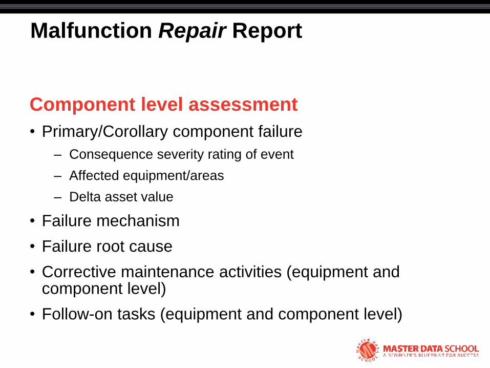
Malfunction Repair Report
Component level assessment
• Primary/Corollary component failure
– Consequence severity rating of event
– Affected equipment/areas
– Delta asset value
• Failure mechanism
• Failure root cause
• Corrective maintenance activities (equipment and component level)
• Follow-on tasks (equipment and component level)

© 2008 Eventure Events. All rights reserved.
Malfunction Report Example
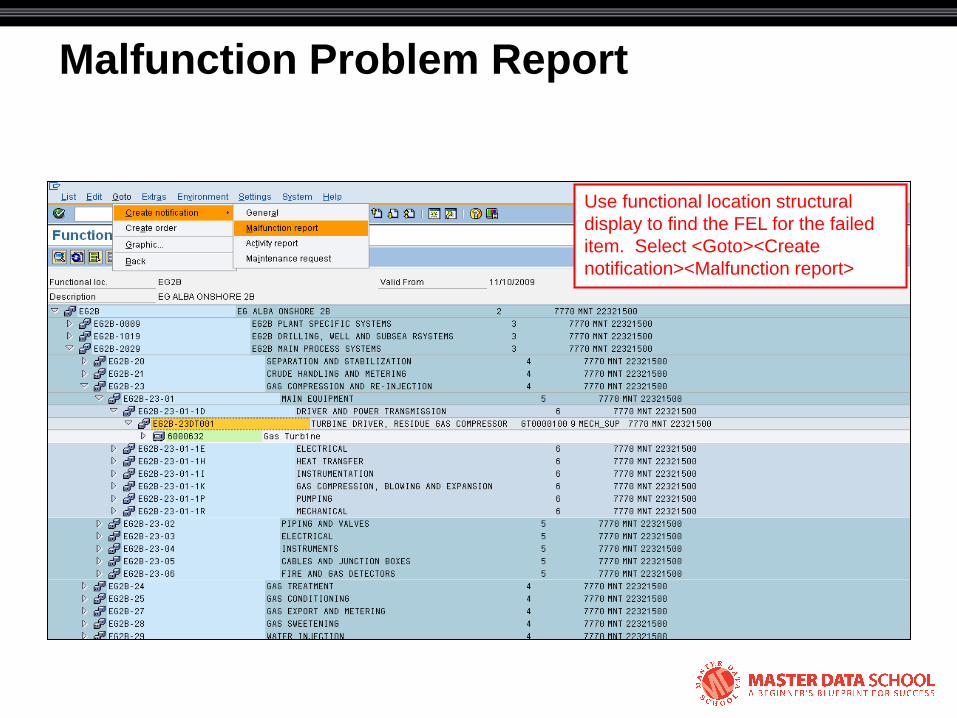
Malfunction Problem Report
Use functional location structural
display to find the FEL for the failed
item. Select <Goto><Create
notification><Malfunction report>
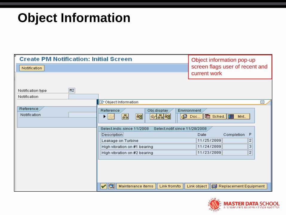
Object Information
Object information pop-up
screen flags user of recent and
current work

Malfunction Problem Report
Breakdown check box prompts
user for malfunction start date
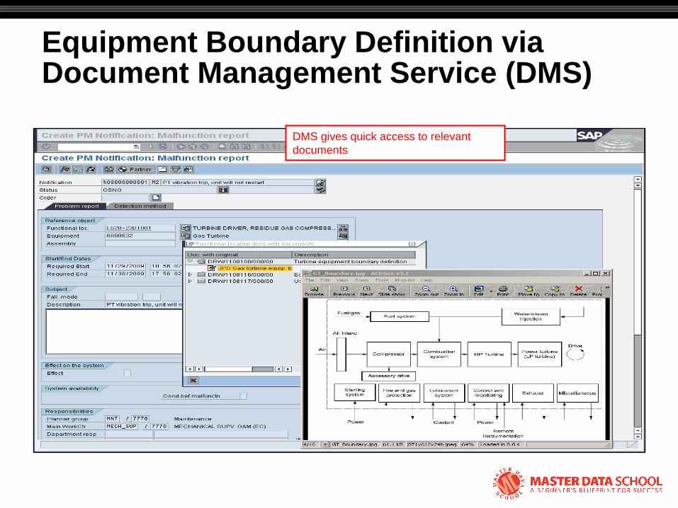
Equipment Boundary Definition via Document Management Service (DMS)
DMS gives quick access to relevant
documents

Operating Condition at Failure and Effect on the System
Responsible person (or position defaults from
reference objects
Effect on the system and
system operating condition at
the time of failure
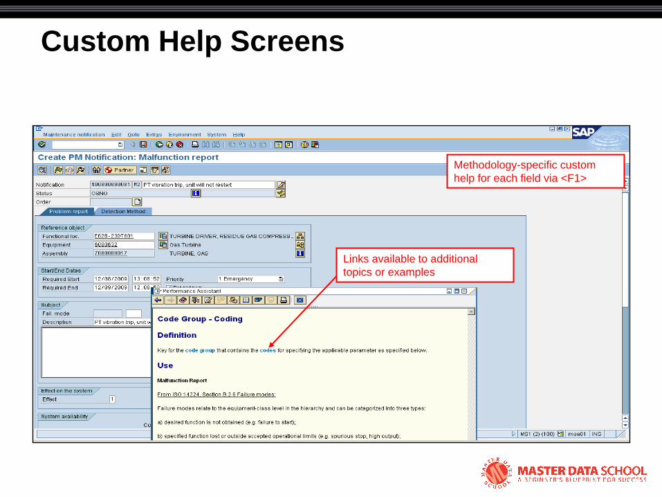
Custom Help Screens
Methodology-specific custom
help for each field via <F1>
Links available to additional
topics or examples
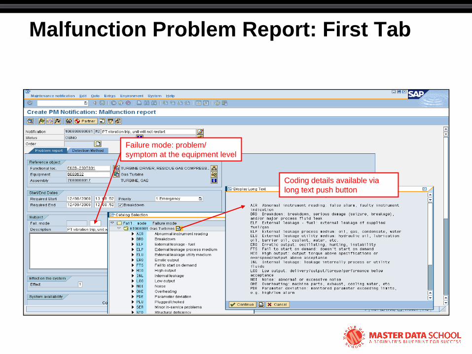
Malfunction Problem Report: First Tab
Failure mode: problem/
symptom at the equipment level
Coding details available via
long text push button
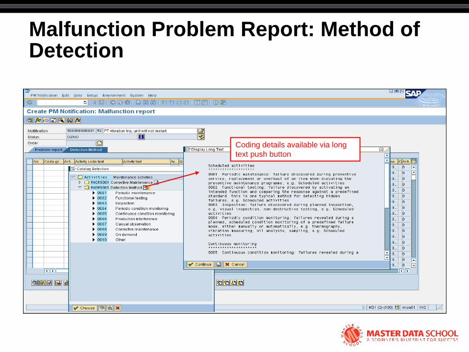
Malfunction Problem Report: Method of Detection
Coding details available via long
text push button
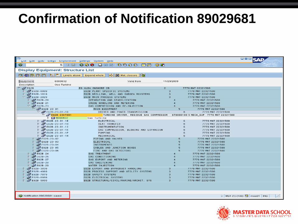
Confirmation of Notification 89029681
Repair Details for EG2B-23DT001
• Failure required PT replacement
• Consequence severity: financial impact of US$8.2 MM
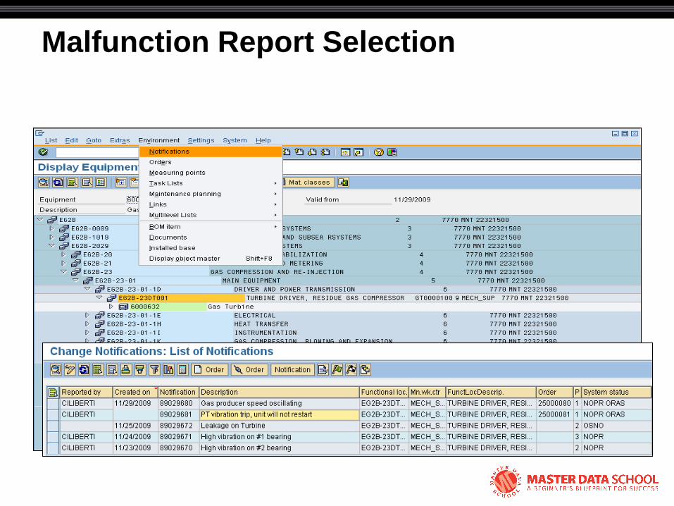
Malfunction Report Selection

Malfunction Repair Report
Transaction variant for change
mode includes additional tabs and
no action box

Equipment Failure Level of Detail Determination

Malfunction Repair Report: Selection of Maintainable Items
The first coding step is selection of the ―first-
out‖ component/maintainable item.
Use progressive levels of detail based on
consequence severity and whether it is a
primary or secondary failure component.
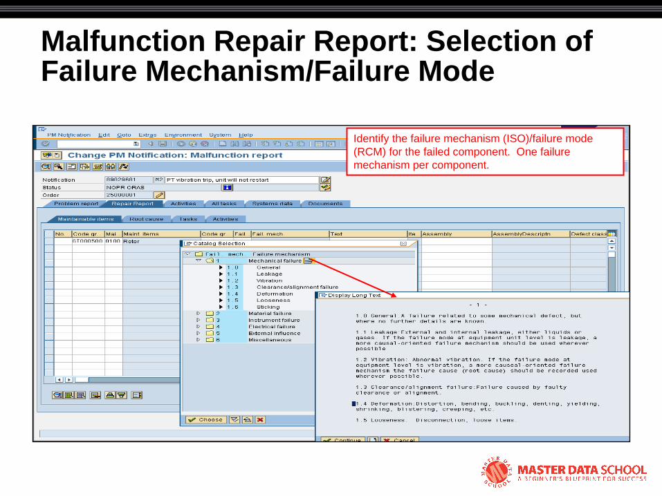
Malfunction Repair Report: Selection of Failure Mechanism/Failure Mode
Identify the failure mechanism (ISO)/failure mode
(RCM) for the failed component. One failure
mechanism per component.
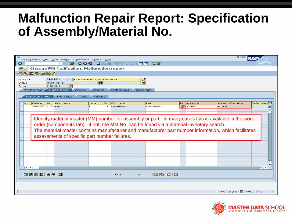
Malfunction Repair Report: Specification of Assembly/Material No.
Identify material master (MM) number for assembly or part. In many cases this is available in the work
order (components tab). If not, the MM No. can be found via a material inventory search.
The material master contains manufacturer and manufacturer part number information, which facilitates
assessments of specific part number failures.
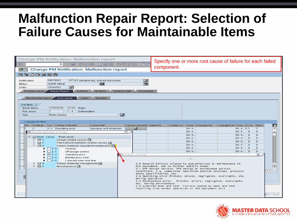
Malfunction Repair Report: Selection of Failure Causes for Maintainable Items
Specify one or more root cause of failure for each failed
component.
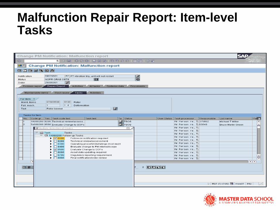
Malfunction Repair Report: Item-level Tasks
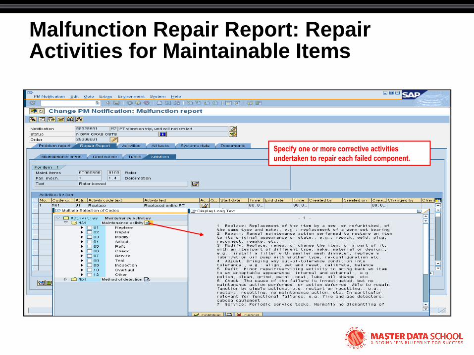
Malfunction Repair Report: Repair Activities for Maintainable Items
Specify one or more corrective activities
undertaken to repair each failed component.
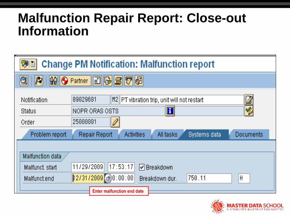
Malfunction Repair Report: Close-out Information
Enter malfunction end date
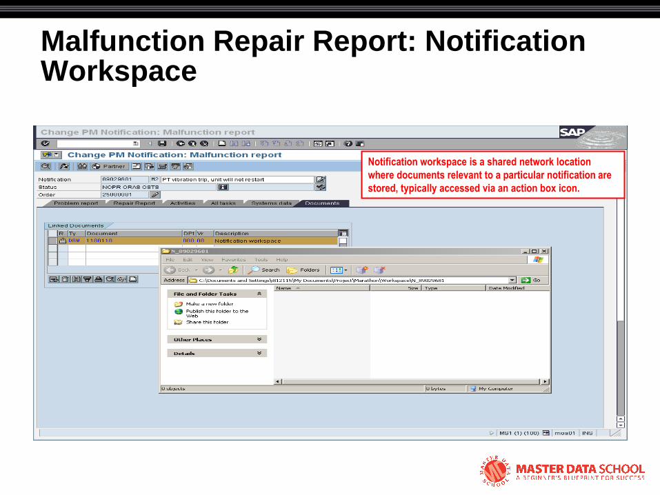
Malfunction Repair Report: Notification Workspace
Notification workspace is a shared network location
where documents relevant to a particular notification are
stored, typically accessed via an action box icon.
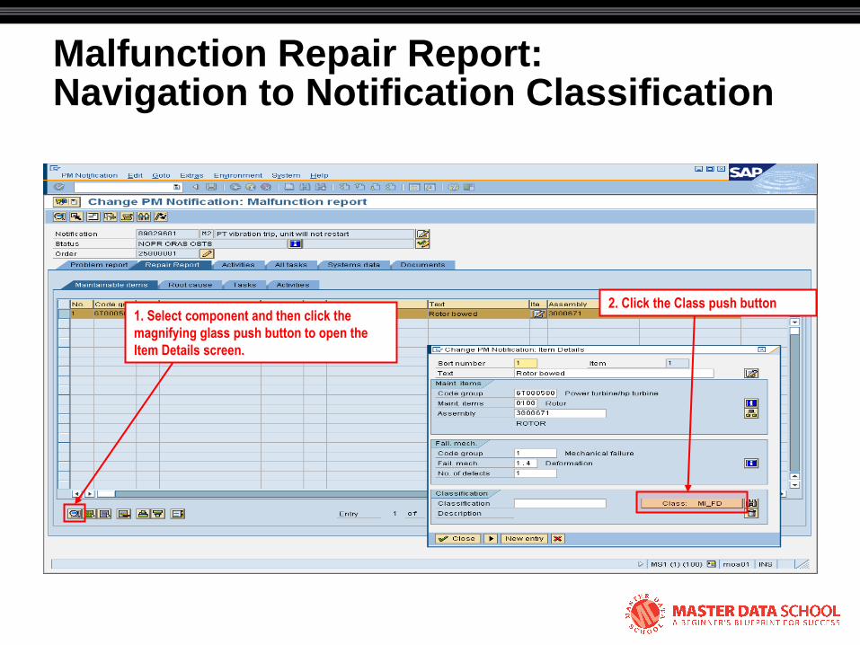
Malfunction Repair Report: Navigation to Notification Classification
1. Select component and then click the
magnifying glass push button to open the
Item Details screen.
2. Click the Class push button
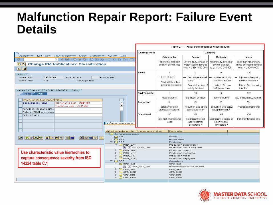
Malfunction Repair Report: Failure Event Details
Use characteristic value hierarchies to
capture consequence severity from ISO
14224 table C.1

Malfunction Repair Report: Follow-up Tasks
Tasks must be confirmed before an order
can be technically completed (TECO)
Responsibility assignments
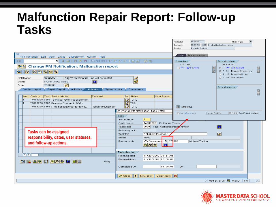
Malfunction Repair Report: Follow-up Tasks
Tasks can be assigned
responsibility, dates, user statuses,
and follow-up actions.
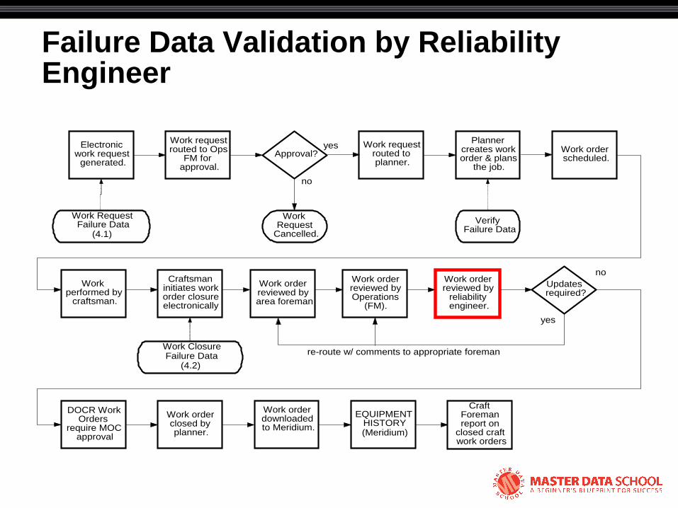
Failure Data Validation by Reliability Engineer
Electronic work request
generated.
Work request routed to Ops
FM for approval.
Work order scheduled.
Planner creates work order & plans
the job.
Work request routed to planner.
Approval?
Work performed by
craftsman.
Work order downloaded to Meridium.
Work order closed by planner.
Craftsman initiates work order closure electronically
Work order reviewed by
reliability engineer.
Updates required?
Work Request
Cancelled.
EQUIPMENT HISTORY (Meridium)
yes
no
no
yes
Work Request Failure Data
(4.1) Verify
Failure Data
Work Closure Failure Data
(4.2)
Craft Foreman report on
closed craft work orders
Work order reviewed by area foreman
Work order reviewed by Operations
(FM).
re-route w/ comments to appropriate foreman (OPS/Maint)
DOCR Work Orders
require MOC approval
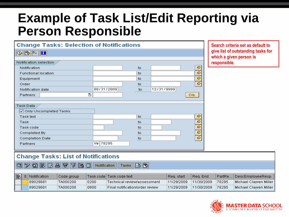
Example of Task List/Edit Reporting via Person Responsible
Search criteria set as default to
give list of outstanding tasks for
which a given person is
responsible.
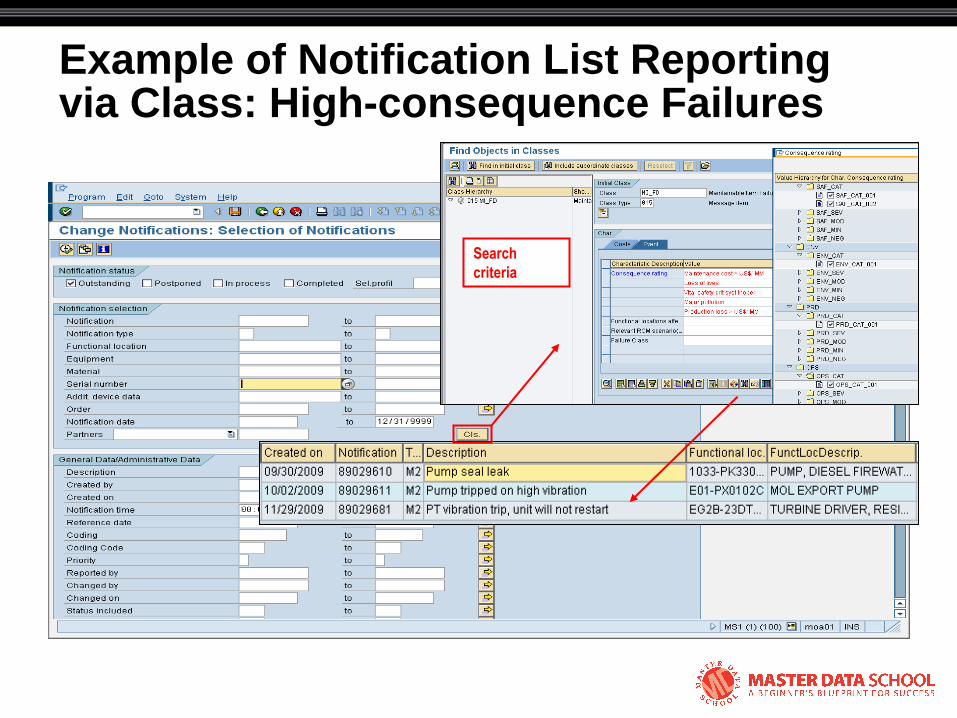
Example of Notification List Reporting via Class: High-consequence Failures
Search
criteria
© 2008 Eventure Events. All rights reserved.
Schema for ISO 14224

Schema Considerations
• Catalog code group updates
– Once a code group code has been used, it cannot be deleted
– Changing the text description changes the code meaning and can affect existing data
• Code group updates involving specific code numbers therefore must be done with versioning
– Schema should allow for updating/versioning

Schema for ISO 14224 Code Sets
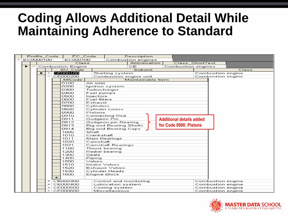
Coding Allows Additional Detail While Maintaining Adherence to Standard
Additional details added
for Code 0900: Pistons
© 2008 Eventure Events. All rights reserved.
Tony Ciliberti, PE
Reliability Dynamics LLC
© 2008 Eventure Events. All rights reserved.
Supplementary Slides
Example of Failure Reporting by Operating Context
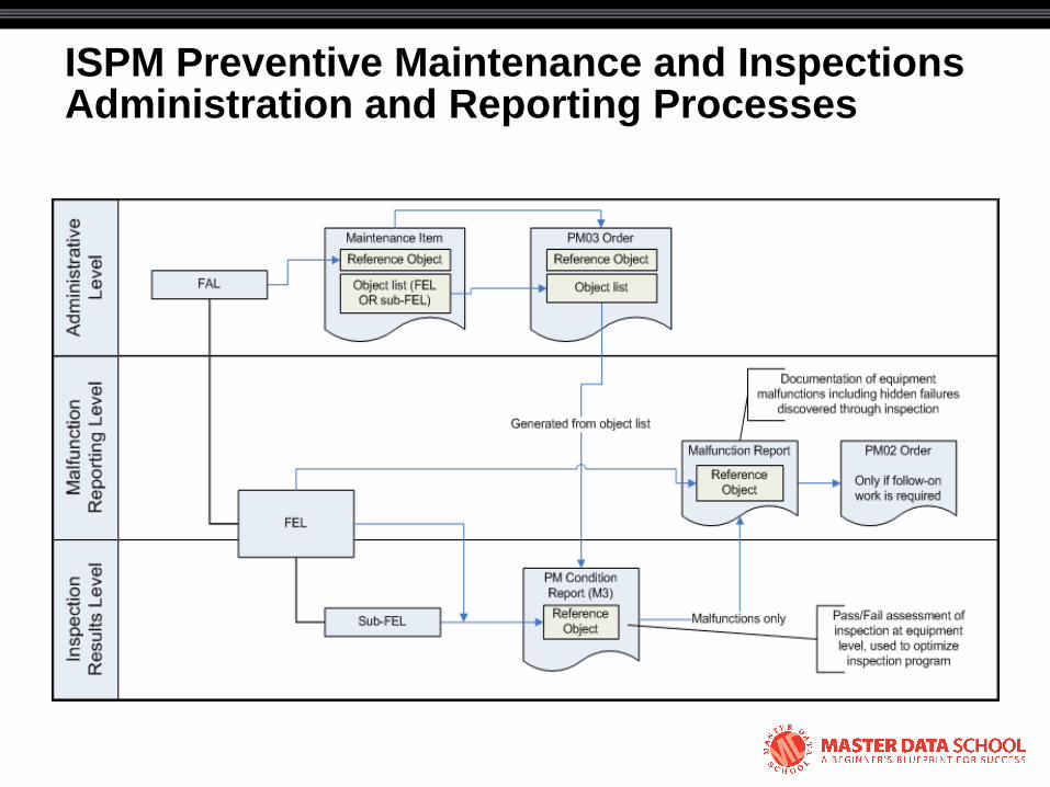
ISPM Preventive Maintenance and Inspections Administration and Reporting Processes
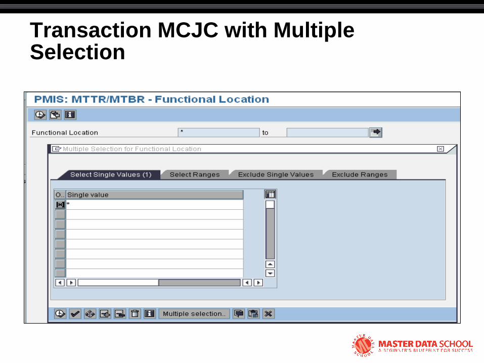
Transaction MCJC with Multiple Selection
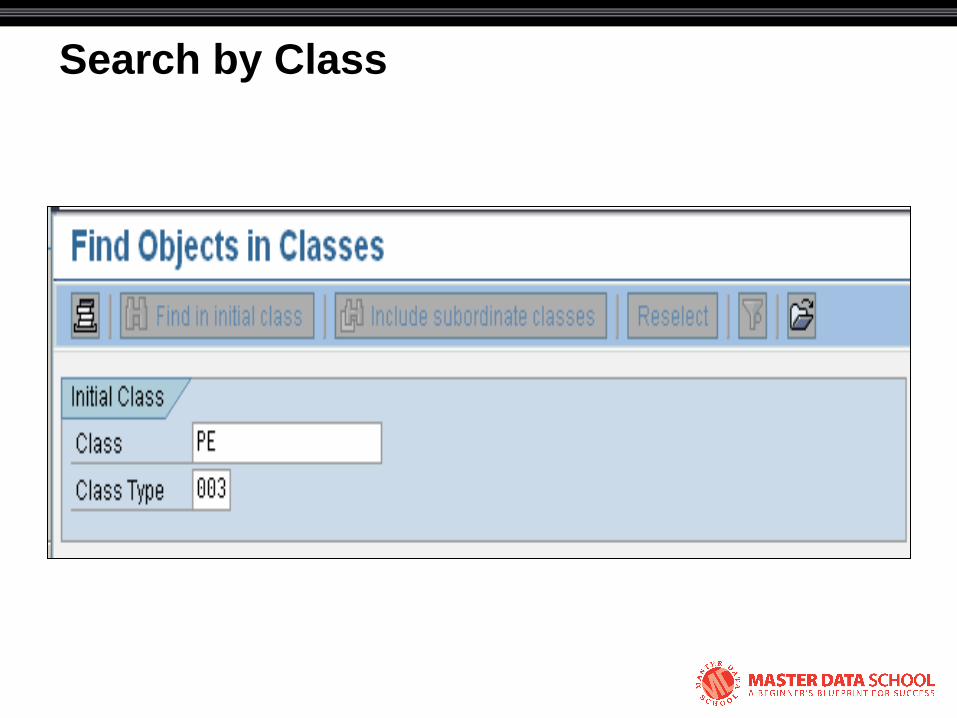
Search by Class
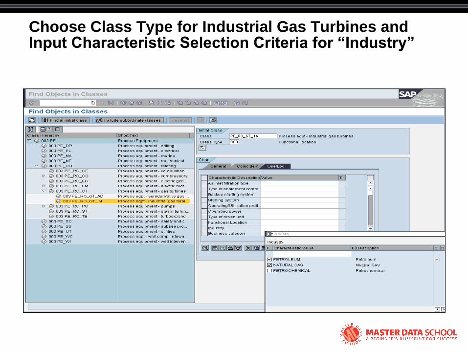
Choose Class Type for Industrial Gas Turbines and Input Characteristic Selection Criteria for “Industry”

Input Characteristic Selection Criteria for “Business Category”
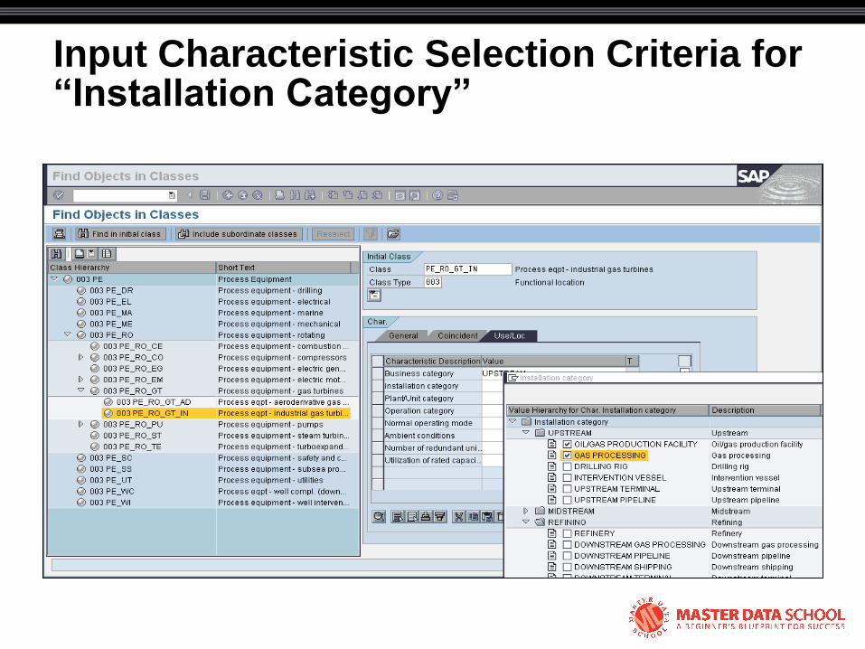
Input Characteristic Selection Criteria for “Installation Category”

Input Characteristic Selection Criteria for “Plant/Unit Category”
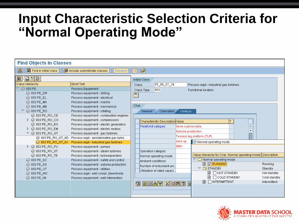
Input Characteristic Selection Criteria for “Normal Operating Mode”

Complete characteristic selection and Execute the Search
Once all selection criteria have been
entered, click the ―Include
subordinate classes‖ push button
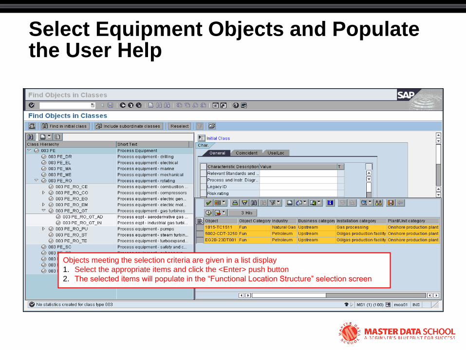
Select Equipment Objects and Populate the User Help
Objects meeting the selection criteria are given in a list display
1. Select the appropriate items and click the <Enter> push button
2. The selected items will populate in the ―Functional Location Structure‖ selection screen

Execute User Help Selections to Populate Selection Variant
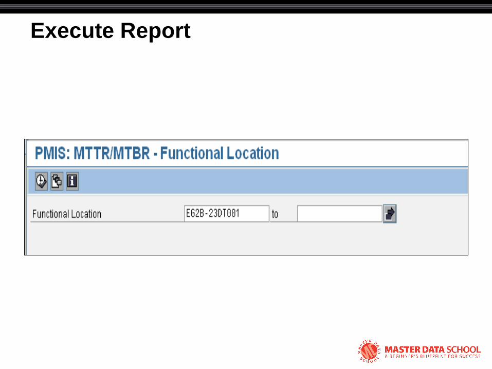
Execute Report
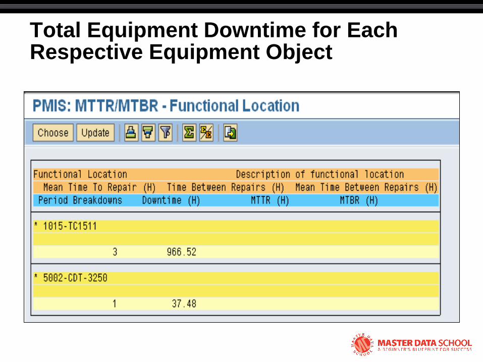
Total Equipment Downtime for Each Respective Equipment Object
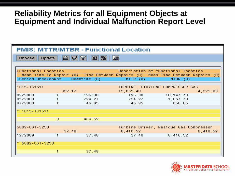
Reliability Metrics for all Equipment Objects at Equipment and Individual Malfunction Report Level

Specific Notification Details for One Equipment Object

© 2008 Eventure Events. All rights reserved.
Tony Ciliberti, PE
Reliability Dynamics LLC