industrial technology tomodernization program-
TRANSCRIPT

GSIENERAL OVNAMICS
FORT WORTH DIVISION
INDUSTRIAL TECHNOLOGYtoMODERNIZATION PROGRAM-
- Phase 2
Final Project Report
ITI
PROJECT 88
IMPROVE MATERIAL HANDLING,COMPUTERIZED STORAGE/RETRIEVAL
SYSTEM (CS/RS)
REVISION 1
DZMTINST~-b7TA HoneywellApprved oi u~bft rleo~( IMilitary Avionics Division
Distribution Umliwzted
89213141

unclassifiedSECR~ C.,ASSIFICA71ON Or PAGE
REPORT DOCUMENTATION PAGEla REPORT SECURITY C.ASStCATION 1o RESTRICTiVE MARKINGS
unclassified None2a. SECURITY CLASSIFICATION AuIHORITY 3 DISTRIBUTION/ AVAILABILITY OF REPORT
2o. DECLASSIFICATION/ DOWNGRADING SCMEDULE UnlimitedNone
4 PERFORMING ORGANIZATION REPORT NuMBER(S) 5 MONITORING ORGANIZATION REPORT NUMBER(S)
None Cited 448307BBH089-0302
6a. NAME OF PERFORMING ORGANIZATION 6o OFFICE SYMBOL 7a. NAME OF MONITORING ORGANIZATION(If appiecaole)
Honeywell, MAVD General Dynamics/Ft. Worth6C. ADDRESS (Otry, State, and ZIP Coae) 7b. ADDRESS (City, State, and ZIP Code)
St. Louis Park, MN 55416 Fort Worth, TX 76101Ba. NAME OF FUNDING /SPONSORING 8b. OFFICE SYMBOL 9. PROCUREMENT INSTRUMENT IDENTIFICATION NUMBER
ORGANIZATION (If applicable) Contract# F33657-82-C-2034F-16 SPO ASD P.O.# 1005262
ac. ADDRESS (City, Stare, and ZIP Code) 10 SOURCE OF FUNDING NUMBERS
PROGRAM PROJECT WORK UNITELEMENT NO. NO. NO. ACCESSION NO.
Dayton, OH 45433
11. TITLE (Include Security Classification)Phase 2 Final Project Report #88 - Improve Material Handling, Computerized Storage/Retrieval System (CS/RS) Revision i
12. RSONAL AUTHOR(S)Robert Knox
13a.2YPE OF REPORT Ii3. TIME COVERED 141AEO5EOT(YaMnh a)u. PAGE COUNTFnal FROM 1986 TO 1988 88,04,01 147
16. SUPPLEMENTARY NOTATION
CDRL ITM-004
17. COSATI CODES ... 18. SUBJECT TERMS (Continue on reverse if necessary and identify by block number)FIELD GROUP SUB-GROUP 1Transformer manufacture, electronic chassis manufacture,13 nA VS/RS, ergonomic work stations.
19. ABSTRACT (Continue on reverse if necessary and identify by block number)'This project addresses the modernization of the factory layout of the electronic chassis,-transformer, and epoxy production areas. This is to be accomplished through more efficientuse of floor space, utilization of automated storage and retrieval systems, streamliningwork flow, and installation of ergonomically designed work cell/work centers. Incorporatioof these changes will result in increased productivity and yields from a reduction in rewortraining, and throughput time. v " -
20. DISTRIBUTION/AVAILABILITY OF ABSTRACT 21. ABSTRACT SECURITY CLASSIFICATION"-UNCLASSIFIEDUNLIMITED [ SAME AS RPT CDTIC USERS unclassified
22a. NAME OF RESPONSIBLE INDIVIDUAL 22o. TELEPHONE (Include Area Code) 22c. OFFICE SYMBOLCaptain Curtis Britt 513-258-4263 1 YPTM
DD FORM 1473, 84 MAR 83 APR edition may be useo untIl exhausted. SECURITY CLASSIFICATION O r THIS PAGEAll other editions are obsolete. unclassified

Honeywell
APRIL 1, 1988
GENERAL DYNAMICSFORT WORTH DIVISION
INDUSTRIAL TECHNOLOGYMODERNIZATION PROGRAM
PHASE 2 FINAL PROJECT REPORT
PROJECT 88
IMPROVE MATERIAL HANDLING,COMPUTERIZED STORAGE/RETRIEVAL
SYSTEM (CS/RS)
REVISION 1
AVIONICS SYSTEMS GROUPMILITARY AVIONICS DIVISION
1625 ZARTMAN AVEST. LOUIS PARK. MN 55416

PROJECT 88
TABLE OF CONTENTS
SECTION ILLE PAGE
1 INTRODUCTION 1
2 PROJECT PURPOSE/OVERVIEW 3
3 TECHNICAL APPROACH 6
4 "AS-IS" PROCESS 39
5 "TO-BE" PROCESS 74
6 PROJECT ASSUMPTIONS 87
7 GROUP TECHNOLOGY CODING SYSTEM ANALYSIS 88
8 PRELIMINARY/FINAL DESIGN AND FINDINGS 90
9 SYSTEM/EQUIPMENT/MACHINING SPECIFICATIONS 117
10 TOOLING 122
11 VENDOR/INDUSTRY ANALYSIS/FINDINGS 123
12 EQUIPMENT/MACHINERY ALTERNATIVES 126
13 MIS REQUIREMENTS/IMPROVEMENTS 127
14 COST BENEFIT ANALYSIS AND PROCEDURE 129
15 IMPLEMENTATION PLAN 136
16 PROBLEMS ENCOUNTERED AND HOW RESOLVED 139
17 AREA FOR FUTURE CONCERNS/DEVELOPMENT 141Accesion For
NTIS CRA&IT IC 1IC TAB [3
Ui'annowr;:edIN SOt I TM Ji , i . . . . .. . .
By . .
Dc strib ,)-I
Avi, W AL, y Codes
Dist S dl
ii sj/1,1

PROJECT 88
LIST OF ILLUSTRATIONS
FIGURE ILE PAGE
3.1-1 PROJECT APPROACH AND METHODOLOGY 7
3.1-2 TYPICAL ITERATIVE PROCESS 9
3.1.1-1 MULTI-DIMENSIONAL SPACE EXAMPLE 11
3.1.2-1 OVERVIEW OF METHODOLOGY 13
3.1.2-2 DEVELOPMENT OF CHASSIS AREA LAYOUT 15
3.2.1-1 WORK CENTER 17
3.2.1-2 WORKSTATION/PROCESS 20
3.2.4-1 VALUATION OF CRITERIA 27
3.3-1 METHODOLOGY FLOW DIAGRAM 28
3.3-2 WORK AREA DESIGN METHODOLOGY 30
3.3-3 WORK AREA (CELL/STATION) ORGANIZATION 33
3.4-1 EQUIPMENT SELECTION APPROACH 34
3.4-2 TOOLING AND EQUIPMENT EVALUATION MATRIX 37
4.0-1 "AS-IS" PRODUCTION PROCESS (FM&TS) 40
4.3-1 FM&TS WORK CENTER STRUCTURES 43
4.4.2-1 CHASSIS GROUP LEADER ACTIVITIES SUMMARY 47
4.4.2-2 TRANSFORMER GROUP LEADER ACTIVITIES SUMMARY 48
4.5-1 CHASSIS & TRANSFORMER AREAS "AS-IS" LOCATION 50
4.5.1-1 "AS-IS" CHASSIS AREA 52
4.5.2-1 TRANSFORMER PRODUCTION AREAS (AS-IS FLOOR PLAN) 53
4.6.1-1 "GENERIC" CHASSIS ASSEMBLY AS-IS PROCESS FLOW 54
4.6.1-2 CURRENT PRE-WIRE WRAP TO WIRE WRAP CHASSIS 56PRODUCTION FLOW
iv

LIST OF ILLUSTRATIONS (CONTINUED)
FIGURE IL.E PAGE
4.6.1-3 CURRENT WIRE WRAP TO POST-WIRE WRAP CHASSIS 57PRODUCTION FLOW
4.6.1-4 CURRENT POST-WIRE WRAP TO DITMCO CHASSIS 58PRODUCTION FLOW
4.6.2-1 "GENERIC" TRANSFORMER ASSEMBLY AS-IS 60PROCESS FLOW
4.6.2-2 TYPICAL TRANSFORMER PRODUCTION FLOW 61
4.7-1 CHASSIS ASSEMBLY AND DITMCO AS-IS MATERIAL FLOW 63
4.7-2 TRANSFORMER ASSEMBLY AND TEST AS-IS 64MATERIAL FLOW
4.8.1-1 GAPOS SYSTEM BLOCK DIAGRAM 66
4.8.1-2 COMPUTERIZED SCHEDULE GENERATION 68
5.1-1 "TO-BE" PRODUCTION PROCESS (FM&TS) 75
5.2-1 CHASSIS & TRANSFORMER AREAS TO-BE LOCATIONS 77
5.2.1-1 "TO-BE" CHASSIS AREA LAYOUT 78
5.2.2-1 "TO-BE" TRANSFORMER AREA LAYOUT 80
8.2.1-1 CHASSIS AREA OPERATIONS GROUPING 93
8.2.1-2 TYPICAL CHASSIS PRODUCTION FLOW 96
8.2.1-3 FUTURE FM&TS - INITIAL AREA LAYOUT 97
8.2.1-4 INITIAL CHASSIS AREA DESIGN 99
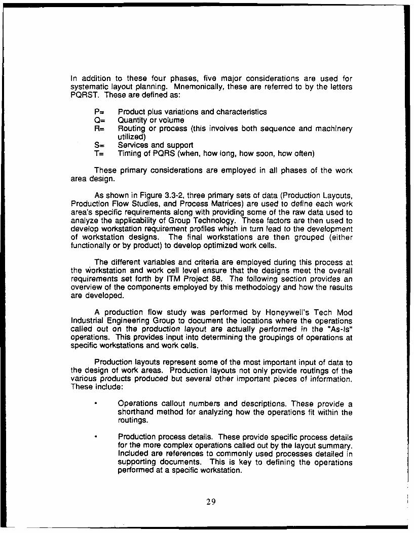
8.2.1-5 "TO-BE" CHASSIS AREA LAYOUT 100
8.2.2-1 TYPICAL TRANSFORMER PRODUCTION FLOW 104
8.2.2-2 "TO-BE" TRANSFORMER AREA LAYOUT 105
8.4.1.1-1 CHASSIS AREA STORAGE VOLUMES 110
8.4.1.1-2 STORAGE MANAGEMENT SYSTEM ELEMENTARY 111SOFTWARE DIAGRAM
v

LIST OF ILLUSTRATIONS (CONTINUED)
E IL PAGE
9.1-1 STORAGE MANAGEMENT SYSTEM ELEMENTARY 119SOFTWARE DIAGRAM
14.0-1 COST BENEFIT ANALYSIS METHODOLOGY 130
14.3-1 PROJECT 88 EXPENDITURE SCHEDULE 134
14.4-1 PROJECT 88 CASH FLOWS 135
15.1-1 PROJECT 88 - IMPLEMENTATION PLAN 137
vi

PROJECT 88
IMPROVE MATERIAL HANDLING,COMPUTERIZED STORAGE/RETRIEVAL
SYSTEM (CS/RS)
SECTION 1
INTRODUCTION
The Flight Management and Targeting Systems (FM & TS) ProductionDepartment is chartered to manage and produce a variety of fixed and rotarywing aircraft electronics in support of the Flight Systems Operation (FSO).
The mission of FM & TS Production is to generate revenue and profit byexecuting production contracts in support of FSO profit and ROI objectives. FM& TS products are typically low volume, high technology devices built underspecific customer contracts. The FM & TS Area produces flight control andhelmet mounted sighting/display systems for fixed and rotary-wing militaryaircraft for various customers. Project 88 is concerned with the area layout andmaterial handling in the Transformer and Chassis assembly areas which areparts of FM & TS.
The Transformer Area may be thought of as a factory within a factory andfunctions basically as a service group which produces a variety of high-qualityprecision magnetics for FM & TS as well as other groups within Honeywell. Theassemblies are built to tight requirements meeting individual device needs. Thegroup also builds engineering models for development programs. As a result,the Transformer Area produces a large variety of transformers making flexabilitywithin the group a high priority.
The primary function of the Chassis Area is the production of chassisassemblies for the devices produced by FM & TS. Some work for other groupswithin Honeywell is also performed but is relatively limited in scope. Thechassis assemblies, which are unique to each type of device, generally consistof a base plate, side and bottom panels, a front panel with I/O connectors andindicators of various sorts, and a heat sink panel on which high powerdissipation components are mounted. Most of the device interconnectionsamong the base plate and I/O connectors is done using semi-automatic wirewrap machines. The remainder of the interconnections are accomplished usinghand solder techniques. The chassis also require various amounts ofmechanical assembly such as riveting, staking, and screw/nut assembly
Project 88 was initiated to provide increased efficiency by the use ofmaterial handling and production flow improvements in the chassis andtransformer areas within FM & TS. These improvements include:
• I II

Chassis Area
- Consolidation of storage for fixturing and tooling- Consolidation of material storage- Floor plan layout emphasizing straight-line flow- "Cluster" arrangement of workstations- Integration of work areas into more efficient groupings- Reduction of material search time by production personnel
Transformer Area
- Consolidation of storage for all process material- Floor plan layout emphaizing minimum flow distances- Productivity enhancements through utilization of modular
workstations- Consolidation of "scattered" work areas- Reduction of material search time by production personnel
These improvements implemented under Project 88 will provide FM & TSwith a significant increase in the efficiency of their manufacturing and help toreduce their overall manufacturing costs.
2

SECTION 2
PROJECT PURPOSE/OVERVIEW
The following section presents an overview of ITM Project 88. Anoverview of the FM & TS Production department and it's primary objectives isalso presented along with a brief description of the Tech Mod efforts atHoneywell.
2.1 FM & TS Overview
Flight Management and Targeting Systems (FM & TS) Production ischartered to manage and produce a variety of fixed and rotary wing aircraftelectronics in support of the Flight Systems Operation (FSO).
The mission of FM & TS Production is to generate revenue and profit byexecuting production contracts in support of FSO profit and ROI objectives. FM& TS products are typically low volume, high technology devices built underspecific customer contracts. The FM & TS Production organization directlyprovides Production Engineering, Production Control, and operatingcapabilities to manage and execute production programs, support engineeringprograms, and provide specialized services to other product areas. Quality,Logistics, Procurement and Manufacturing Technical Services support isprovided to FM & TS Production by Honeywell's Military Avionics Division(MAvD) central organizations.
The priority objective within FM & TS Production is to produce qualityproducts within cost goals. Additional objectives include flexibility anddependability with the emphasis differing slightly in each of the focusedfactories.
2.2 FM & TS and Tech Mod
The USAF Tech Mod program was instituted to provide strategicplanning and develop facility modernization projects that reduce manufacturingcosts, improve product quality and reliability, and reduce manufacturingthroughput time. In addition, the Tech Mod program has been chartered withassuring the capability for a rapid increase in production in the event of nationalemergency.
Under the guidance of the Tech Mod projram, Honeywell has definedseveral areas for improving production in the Flight Management and TargetingProduction facility in St. Louis Park, Minnesota. ITM Project 88 for upgradingFM & TS Chassis and Transformer Area Production has been defined and isdescribed in the following section.
3

2.3 Project 88 Strategic Goals and Objectives
FM & TS Production has defined several major objectives that are beingincorporated in their future business planning. These objectives includeincreasing the flexibility of their operations and improving product quality, whilemaintaining a high degree of cost control.
Cost control is the overriding objective of FM & TS Production planning.This control must be maintained for both existing program production as well asfor new programs. The cost control efforts underway in FM & TS Production arewide-ranging and are being applied at every level of the organization.Examoles of this can be seen in the current implementation of the HMS/BOSMRPII system in St. Louis Park as well as the implementation of the FactoryData Collection System. In addition to controlling costs, the following objectiveshave been defined as critical to FM & TS's future production operations:
Increase flexibility of operations. FM & TS willmanufacture between six and ten products at anyparticular time and with the introduction of newprograms which introduce both process and productchanges, the current operations must remain flexiblein adapting to these changes while still maintainingthe capability of supporting existing programs.
Increase product quality. By achieving 100%conformance with customer requirements, Honeywellwill be viewed as the leading supplier of MilitaryAvionics products. While this is of important strategicvalue from a marketi:ig perspective, it can also havea direct effect on lowering the manufacturing costs insuch areas as reducing rework and scrap.
Reducing production lead times. Customerrequirements dictate shorter production lead timesand these will be accomplished through developingmore streamlined process, material, and productionflows. Improvements in information processing (suchas HMS and FDC) will also aid in reducingproduction lead times.
ITM Project 88 has been defined by the Honeywell Tech Mod ProjectTeam for implementation in Flight Management and Targeting SystemsProduction. This project, as defined by the Tech Mod Project Team, isdescribed below.
ITM Project 88 addresses the modernization of the factory layout of thechassis, transformer, and epoxy areas within the FM & TS department. Thismodernization is to be accomplished through more efficient use of floor space,utilization of vertical storage and retrieval systems (VS/RS), consolidation of
4

transformer assembly operations, streamlining work flow, and installation ofergonomically designed work cell/work centers. The benefits associated withthe implementation of ITM Project 88 include:
0 Increased productivity in transformer area winding, leadset,and epoxy operations
0 Clustering of higher volume activities
0 Reduced dependency on material movement by supportpersonnel
* Reduced Group Leader effort in material search andtransport
* Reduced production control effort in material search andtransport
* Centralized, high efficiency material storage
• Significant reduction in work flow distances
• More efficient flow of work within operational areas
• Built in potential for upgrade to fully integrated materialtracking system
This project represents a significant part of the overall Tech Mod programcurrently being administered in Honeywell's Military Avionics Division.
5

SECTION 3
TECHNICAL APPROACH
The following subsections describe the general approach andmethodology adopted by the Project 88 team for this project.
The first subsection describes the overall approach and methodology forperforming an in-depth analysis of the FM & TS chassis and transformer area'soperations and presents the methods employed in developing a structureddesign for more advanced operations and material handling methods. Inaddition, this section presents the evaluation methods used to establishtechnical requirements which define the possible material handlingimprovements within the Chassis and Transformer operations.
The second subsection introduces the philosophy of developing amanufacturing operations structure by first defining hierarchical levelsemployed in a manufacturing environment and the characteristics of productionwith respect to the impact of decisions concerning product versus processorientation (or a mix of these) at each of these levels. The ITM Project 88objectives are then described as they relate to each of the hierarchical levelsdefined and the variables and criteria necessary for making recommendationsfor each of these levels is presented. These criteria are utilized moreextensively in Sections 4 and 5 in defining and developing the advanceddesign of the transformer and chassis areas.
Subsection three presents the factors that affect the design of work areas(both work cells and workstations). The methodology of developingrequirements for optimally designed work cells and workstations is presentedalong with the development of specific material handling requirements.Ergonomic design philosophies are described as they were employed in thedevelopment of the specific work stations as well as the overall area layoutsand material handling designs.
The final subsection describes the approach developed for selectingmaterial handling equipment. This includes the methodology used to developrequirements for equipment, the selection criteria, and the high level evaluationmatrices.
3.1 Overview of Project Approach and Methodology
The project team has developed an overall approach for performing ITMProject 88 which is summarized in Figure 3.1-1. During the initial phase of theproject, this approach required the collection of a great deal of information,including:
6

Personnel Project 80's General ExistingInterviews Statement Business Equipment
of Work Information Information
FaiiyTech Mod Product SystemsFailtyTor Pr gramn Information Information
OperationsDescription
PhysicalEnvironments
Product'onFlow
Material
InformationFlow
CurrentNew systems,CMSaeo Operations operations,
Me-Ar Anaysis& equipmentPrnilsImprovement
New operations,Tevaltony Recommendations strategy & tactics
FutureOperations
Design
PhysicalEnvironments
Production/MaterilV
Information Flow
MigrationPlan
Cost BenefitAnalysis
Figure 3.1-1 Project Approach and Methodology
7

* Project 88 Statement of Work* Tech Mod Program Goals* FM & TS Business0 FM & TS Products* Personnel Interviews0 Facility Tours• Chassis and Transformers Area Existing Material Handling
Methods and Equipment0 Chassis and Transformers Area Existing Systems
This information was assimilated by the project team and presented in aseries of meetings designed to assure that the project team fully understood thevarious facets of the FM & TS Chassis and Transformer current operations. Theanalysis resulting from this exercise, along with the technologicalunderstanding of similar operations to that of FM & TS, were then utilized indeveloping the future material handling operations design as well as therelayout of the area to provide a more streamlined production flow, materialflow, and information flow.
The final phase in this process is the development of an implementationplan which outlines the implementation steps required to achieve the final planand a cost benefit analysis which defines the benefits in respect to thenecessary investment and the time required to realize a return on Honeywell'sinvestment.
In utilizing the approach described above, the project team has foundthat an iterative process methodology would yield the best results in the creativeprocess of designing systems and operations similar to the FM & TS operations.This methodology is particularly applicable in the type of environment, both froma physical perspective as well as a business and management perspective, thatexists for the Honeywell project team.
In the early stages of the project, the iterative process consisted of thepresentation of information collected and assimilated by the project team in aconcise format. After an agreement as to the adequacy of the presentation wasreached at this level, the process moved further into more detailed levels. Thisis the basis of the iterative process. Further iterations addressed the first initialconceptual levels of design and, as more detail was agreed upon, more preciseelements of the design were put into place.
The feedback generated as a result of each of these presentations andthe incorporation of this information into the final report assures that the resultsof the overall design process are compatible with the desires and ideasexpressed by the user's and management organization. The iterative designprocess is illustrated in a conceptual manner in Figure 3.1-2.
8

ProjectInitiation
Information Program Goal Related Experience,Collection I -. l and l Expertise, Ideas,OperationsJ I , Requirements) and Wants )
Euipr mt Honeywell Team
-- Etc. Other Sources
Information Assimilation Information* Concepts Creation nlyis- Deductive Results .)/Te.chnology I
Iterativeatin
nlter i s ,Results Presentation]
Comments and Remarks
ResultsApproved
Figure 3.1-2 Typical Iterative Process
9

3.1.1 Operations Analysis
The goal of a comprehensive operations analysis is to first describe thecurrent operations of Honeywell's FM & TS Chassis and Transformer areas.Based upon this description, specific areas and operations are defined (inaccordance with the statement of work) for further analysis as they significantlyimpact the direct or indirect costs of FM & TS production. This analysis thenprovides the foundation upon which the operations of the future is designed.
The absolute and definitive areas which are identified as cost drivers inthe Transformer and Chassis operations lie in a multi-dimensional space withcomplex interrelated dimensions that are difficult to delineate. The primary taskin the analysis phase is to determine the methods and approach required todefine and analyze an issue which is extremely complex. As shown in Figure3.1.1-1, this multi-dimensional space is characterized by the hierarchical levelsexisting within the FM & TS organization and the specific objectives of ITMProject 88.
By specifying the general objectives to be achieved, it is possible toreduce the complexity of these interrelated dimensions and to define objectivesfor each of the levels of operations and analyze improvements to be made ateach level. Once these objectives have been defined at a specific level, it isthen necessary to establish the significant variables and criteria that willinfluence the analysis and recommendations made for each of these levels.
While the variables and criteria are defined more comprehensively inSection 3.2.3, they are briefly summarized as:
Production- Physical Arrangement- Process Flow- Group Technology
Material- Material Management- Material Handling
Information- Systems- Control Networks
In addition, several criteria have also been developed. These include suchconsiderations as cost (capital investment, ROI, etc.) as well as product profilesand several other areas.
Once the project objectives have been finalized, the hierarchical levelsdefined, and the criteria and variables established, it is then possible to definethe correlations between all of these dimensions and begin the structured
10

se~i~e~qQ 38~O0
CZ
.~ >
CX
0
Figue 3..1- Muli-DmensonalSpae Exmpl

design process as described in the following section and utilized throughout theprogress of this report.
3.1.2 Structured Design Approach
The structured design approach employed by the project team is directlydependent upon a detailed analysis of the specific FM & TS operations for thetransformer and chassis areas. The previous section described themethodology used to approach a large, complex, interrelated structure and"break down" that structure into discrete entities (i.e., work- cells andworkstations). Once the operations have been analyzed at a discrete enoughlevel to understand the processes and unique characteristics at each level, it ispossible to rebuild each of the levels progressively to transform the operationsinto a more advanced manufacturing structure.
A general overview of this "rebuilding" process is presented in Figure3.1.2-1. Once the analysis phase has been developed to the workstation andprocess level, it is then beneficial to analyze each product and discrete processin respect to Group Technology. The term Group Technology has beenalternately used to describe
1) a process of codifying parts in a computer database in orderto group similar parts or
2) the organization of product families into cells in order toeliminate the duplication of resources.
A codifying of all parts used at Honeywell would be an extremely largeundertaking and would require the coordination of several divisions to assureits effectiveness and to realize significant cost savings. While this would be anworthwhile endeavor for Honeywell, this was not a reasonable task for theimplementation of ITM Project 88. However, the project team developedmatrices to define the specific miscellaneous hardware used in the chassis andtransformer areas as an aid in establishing proposed equipment andworkstation requirements.
In addition, large scale matrices were developed which correlated theHoneywell part number (of each assembly, sub-assembly, and component partof all products produced by FM & TS) with the operations and the standardhours required to perform these operations. These correlation matricesprovided important information for grouping similar processes at workstations,defining the equipment required at each specific type of workstation as well asthe actual number of workstations required for each of these groupings ofoperations.
In accordance with ITM Project 88, a number of other factors, which areprimarily concerned with the overall area layout and the material handlingrequirements for these areas, have influenced the general workstation design
12

Group Technology Group Technology
(Product/Process) (Product/Process)
Characteristics of Characteristics ofWorkstation Workstation
Equipment Requirements Equipment RequirementsDefinition Definition
Workstation Design Workstation Design
EEV1DW
Work Cell Design
Relationship of Cells Within Factory
Figure 3.1.2-1 Overview of Methodology
13

requirements. The relationship of these factors to the overall design process isshown in Figure 3.1.2-2. The primary additional factors which also affect thedesign definition include:
* Production Volumes* Material Movement and Transport Means* Workstation Storage Requirements* Work Area Storage Requirements
Once the design of new workstations, processes, and additionalrequirements for testing and other areas are defined, it is necessary to presentspecific technical solutions that can be implemented in the most efficient andeffective manner.
3.2 Manufacturing Operations Structure
The manufacturing operations in Honeywell's FM & TS Production areahave been structured both to reflect an overall Honeywell approach to divisionalresponsibility and in response to the changing product and productionrequirements. In order to develop the optimum manufacturing solutions for FM& TS production, it is necessary to "break down" the manufacturing operationsstructure into more discrete entities or levels that can be analyzed separatelybefore "restructuring" the operations to provide a global alternative to theircurrent operations.
Once these levels have been defined, a trade-off analysis can be maderegarding production principles at each of these levels and for the effect thecharacteristics of these principles have at each of the levels and the sub-groupswithin these levels. The primary production principles described in this sectioncan be defined in terms of either product orientation or process orientation.
The analysis of operations structure is applied to the specific objectivesof ITM Project 88. This provides an assessment of the impact of these principlesat each level addressed by the project and defines the project objectives withrespect to each level.
Following the detailed definition of the project's objectives, the specificvariables that influence decision making at each of the levels and the criteriathat must be met to accomplish the project objectives are determined. Thevariables can be defined as global considerations for developing cost driversfor the overall project. The criteria then provide the specific elements whichmust be evaluated for specific ROI and payback analysis that will determine thejustifiability of each of the improvements recommended.
3.2.1 Definition of Hierarchical Manufacturing Levels
The current trends in analyzing manufacturing operations structures is toview the manufacturing structure in a hierarchical manner. This approach
14

GroupTechnology
Matrix
Production Standard DevelopVolumes Hours/Ops ToolingPareto Part # Reqs.
Matrix
Material Group like Define W/SMovement processes StorageAnalysis for W/S Reqs.
definition
Definition Establish Defineof Cells/ Std. Hrs. for Breakpoint Design W/SLayout W/S Ops for add W/S Storage
Analysis Throughput Projections
Define Establish # DevelopWork Area of W/S req. W/Srrangemen to meet '86 Design
Volumes Reqs.
DesignWork
Station
Figure 3.1.2-2 Development of Chassis Area Layout
15

provides the basis for determining the ways in which manufacturing isperformed as well as the influence of the structure on the actual manufacturingoperations.
The primary divisions that are typically defined are:
* Company* Division* Factory* Work Center* Work Cell* Workstation/Process
Each of the hierarchical levels below the Division level is described indetail in the following paragraphs. While some of these descriptions may implycomputer controlled actions at each level, these actions are actually possibleeither through a computer control system or through a manual "paper-based"system. Subsequent sections (Sections 4 and 5) define each of the hierarchicallevels as they apply to the current FM & TS operations and the proposed FM &TS manufacturing operations respectively.
Factory
The factory level (also known as the plant level) is responsible for allproduction operations for a related set of products. In response to divisional orcorporate forecasts, the factory develops a manufacturing resource plan toachieve these goals. In addition, the factory is responsible for monitoring theoverall efficiency and productivity of the manufacturing resources.
Included within the factory are the shipping and receiving functions,warehousing, administration and manufacturing services, data processing, andthe entities which are responsible for the production processes.
From a systems perspective, the factory level is where MRP (MaterialRequirements Planning) or MRP II (Manufacturing Resources Planning)systems reside. These types of systems take a macro view of the productionoperations as an integral part of the entire operation of the factory. Productionand the processes entailed are viewed from this level as financial entities andtherefore, the most important information required at this level is the rate ofproduction, inventory levels, production completions, and other financial relateddata.
Work Center
The work center level (which is shown conceptually in Figure 3.2.1-1) isresponsible for the production of a specific product line or a set of related sub-assemblies or products. In a general view, the work center is responsible for
16

Scanner M
oWor0 I InlStation
WorkWork CellSP Lj StationWokCl
S Work
[] I B StationS u S
R f RS f S Conveyor
rlr []e Transporation
Cell
C Test/Inspection
o Cell
Responsible for production of a specific product line or set ofrelated subassemblies
Optimizes near-term resource schedules to meet factoryproduction plans (specific resource allocations)
Authorizes actual manufacture of products associated withthe work centerMonitors performance and near-term availability of work centerresources.
Figure 3.2.1-1 Work Center
17

coordinating the actual manufacture of a product involving all of the requiredprocesses and procedures.
To meet production objectives, the work center is responsible for agreater range of tracking production than a units/time period level. The workcenter allocates specific resources and provides near-term scheduling to meetthe overall factory production plans. In performing this, it is responsible forauthorizing the actual manufacture of products, the release of materials to themanufacturing floor, as well as the transference of product from manufacturingto shipping.
The work center is also responsible for monitoring the performance andnear-term availability of work center resources. These resources includeinventory levels and replenishment, material transfer and transportation means,processes, in-process storage, and several others.
Work Cell
The work cell (whether physical or logical) is responsible for performing aspecific set of related operations or factory services. This can be defined as aspecific sub-assembly or a specific process required by all sub-assemblies orassemblies. The work cell is also responsible for coordinating all activitiesamong the workstations within the cell. This includes authorization ofworkstation activation and deactivation, tool changes, intra-cell materialhandling, and other inter-station activities.
The work cell also monitors at a discrete level each of the workstationswithin the cell as far as exact location and current process being performed.With this data, the work cell can then direct corrective action with respect toexception conditions at workstations or can notify the local operator as to arequired action.
Workstation
Workstations are responsible for controlling the execution of one or morelinked processes. The workstation initiates commands for specific actions to theappropriate process. In addition, the workstation monitors process activitiesthrough command acknowledgements and exception alerts.
Process
Processes are specific steps executed within an operation. At this lowlevel, process controls provide acknowledgement of each command receivedand report each relevant action taken. As with workstations, the process controllevel reports exception conditions with respect to specific machine operations.
18

A conceptual overview of the workstation and process responsibilities is
shown in Figure 3.2.1-2.
3.2.2 Production Characteristics
Production characteristics describe the type of production operations thatare employed for a particular set of products and are dependent upon a varietyof factors including build schedule, lot sizes, product characteristics, and manyother factors. The primary division of production characteristics is betweenfunctionally oriented (or process oriented) manufacturing and product orientedmanufacturing. Additionally, characteristics of production may define the needfor a mix between a functional and product orientation.
The assignment of production characteristics need not be global for anorganization but should be determined when applied to each of the hierarchicallevels within the factory. The following paragraphs briefly summarize the majordistinctions between process and product manufacturing orientations and whatthe determining factors are in applying these characteristics at eachmanufacturing level.
Product Oriented Manufacturing
Product oriented manufacturing is characterized by grouping all functionscommon to an individual product in a close proximity or physical area. Thismeans that each work area is strictly dedicated to the manufacture of individualproducts. In this regard, a major requirement of product oriented manufacturingis that there be sufficient capital equipment allocated to support each individualproduct line.
Process controls are characterized as those required specifically on aproduct by product basis, however production control is simplified by the singleproduct focus. Inspection, under production oriented manufacturing, is againproduct oriented and is facilitated by a step-by-step process that follows theproduct through the production cycle. Training materials and aids must also bedeveloped on a per product basis for each operation performed.
Material control is dedicated to each product and requires multi-pointmaterial distribution control for allocation of parts.
Functional (Process) Oriented Manufacturing
In contrast to product oriented manufacturing, a functional orientationgroups processes common to all products in a physical area. This can providean advantage for products requiring that a high degree of repetitive tasks beperformed for the manufacture of the product. In that regard, while operators donot require shifting from processes, a level of sameness in the work candecrease productivity.
19

Vision~Inspection
RotaryTest
i ( TstR~ary Stand
Build
Fixtures
BuildFixtures
Material loading/Unloading
Workstation: Responsible for controlling execution of one or more linkedprocesses
Directs commands for specific action to appropriate processesMonitors process activity through command acknowledgements
and exception alertsAcknowledges work cell commands
Process: Responsible for executing specific steps within an operationProvides acknowledgement of each command received and
reports each relavent action takenReports exception conditions with respect to machine
operation
Figure 3.2.1-2 WorkstationlProcess
20

One of the major benefits of functionally oriented manufacturing is thatproduction resources (such as capital equipment) is centralized and requiresless duplication. As part of this benefit, product flow is forced through acommon location, allowing for more control and tracking of productionprocesses. This concentration on the process allows development of universalprocess controls and the development of more generic work aids and training.
Material handling and control becomes more concentrated under thisscenario as limited classes of material are established for each single point ofuse or work area. In contrast, production control must be more spread out tomonitor more production points for an individual product.
Combined Functional/Product Orientation
The combined functional/product manufacturing orientation representsthe most common organization of characteristics in most manufacturingenvironments. This mix allows processes that are common to all products to begrouped in separate, distinct physical areas. In turn, processes that are uniqueto a specific product can be isolated in a separate physical area for moreefficient production control.
The functional/product mix provides defined integration points forproduct/process routing splits and merges. Material handling is optimized bythe ability to define specific material class requirements for each of the workareas. In addition, resource utilization is optimized due to the fact that resourceorientation is defined for the most productive work flow.
3.2.3 Definition of ITM Project 88 Objectives
ITM Project 88 has a defined objective to increase the efficiency of thetransformer and chassis areas by the use of improved material handlingsystems. ITM Project 88 addresses the modernization of the factory layout ofthe chassis, transformer, and epoxy areas within the Flight Management andTargeting Systems (FM & TS) department. This modernization is to beaccomplished through more efficient use of floor space, utilization of verticalstorage and retrieval systems (VS/RS), streamlining work flow, and installationof ergonomically designed work cell/work centers.
The primary concentration of efforts for performing ITM Project 88 arefocused on the overall stncture and layout of the chassis and transformerareas, workstation design improvements, and improved material handlingmeans.
21

3.2.4 Definition of Variables and Criteria
The variables and criteria for Project 88 are used to define morediscretely the areas that most benefit from material handling and productionflow improvements. The variables represent the major aspects of productionoperations while the criteria define the ways in which improvements can bemeasured.
Manufacturing operations variables are those areas within amanufacturing operation that are changed or affected by changes within theoperations to optimize production. These variables are defined by three majorcategories:
* Production* Material* Information
Production Variables
Structure. The structure of production can be defined either in respect tothe hierarchical levels defined earlier or as a specific operation's organizationalstructure. Organizational structures can greatly affect the flow of production,especially in the structure's responsiveness to the manufacturing flow problemsand in its facility to implement modifications and changes to the manufacturingprocesses.
Layout. There are a number of ways a production area can be physicallyorganized on the shop floor and this physical layout can greatly affect themanufacturing production flow. While this area is described in greater detail inthe following section, it should be noted that there are a number of ways that amanufacturing area can be laid out but the specific layout depends upon thegoals for the area and the criteria defined for that area.
Process Flow. In conjunction with layout, process flow can be optimizedto group resources in a specific area and to consolidate material handlingefforts. The definition of an optimized process flow is a major factor in definingan optimum physical layout.
Group Technology. Group technology addresses two major operationalphilosophies, one concerned more with the cellular organization of processesand work areas, and the other focusing on specific products and productfamilies. These concepts are explored in detail in Section 3.3.
Material Variables
Material Management. The effective control and management ofmaterials is key to efficient and profitable manufacturing. Material management
22

encompasses scheduling mate, ials (both raw materials and work-in-process)as well as being able to monitor material usage and production completions.
Material Handling. Material Handling ranges from totally manual to fullyautomated and the selection of the appropriate material handling methodsdepends upon the definition of the appropriate criteria such as productcharacteristics and movement distances required.
Information Variables
Systems. Information systems can, like material handling methods,range from totally manual to fully automated. All manufacturing processes atany level include production information systems and it is important to definesystems that are responsive to the manufacture of a product and that aid in thatproduction rather than affect it adversely.
Control Networks. These networks, either formal or informal, serve tomonitor and control production processes more accurately, thereby allowingother operations to be targeted for improvements. With the advent of computercontrolled networks, much of the lower level control functions can now bereadily automated dependent upon the specific criteria for a process.
Production Criteria
Production criteria are necessary for the development of anyfacility/operations improvement program. These criteria cover a wide range andan all inclusive list would be far too long for consideration in any project. Thefollowing paragraphs describe some of the major production criteria that havebeen used in the development of improvements for the FM & TS ITM Project 88.
Capital Investment (Duplication of Equipment)
Capital equipment should be considered for duplication when productvolume processed requires time in excess of 96 hours/week (greater than 2shifts per 24 hours) or the unit is critical to production such that down time inexcess of one shift would seriously impact production.
Square Footage Required (Proc.ess vs. Product)
Consideration must be made for flow lines and/or product queues. If thearea occupied by single product-related process exceeds 50% of spaceutilized, the process should be incorporated into product flow. This allowsprocesses to function at peak efficiency and product specific operations to beperformed in an optimum area.
23

Process Time for Separate Operations
If process time at a remote location (including movement) exceeds oneshift, it should be incorporated into the product flow. Alternatively, a facilityrelayout may be considered to bring separate operations together. (Obviously,the cost effectiveness of process incorporation of facility relayout is governed byproduct volume, available capital, and facility costs.)
Product Profile
The following factors dictate product oriented assembly (versus processoriented) to avoid quality/damage problems:
Product Size. Weight or volume of product precludesmovement to a remote processing point without riskof damage.
Process Complexity. Process employed has anintricate or extensive set of steps necessary toaccomplish a particular task making it inconvenientor subject to error if intermixed with other processes.
Parts Count. Unit has high number of unique partswhich, by organizing in a single product workstation,ensure higher quality and throughput whencontrasted with a multi-product workstation.
Special Handling Requirements. Unit configurationor delicate nature dictates minimizing handling ortransport during intermediate assembly steps.
Material Transport Related Factors
If time taken for
• Material Movement (distance)* Queueing time (Wait States)
exceeds 20% of actual processing time, an operation should beconsidered for product line orientation.
Personnel (Skill Level, Training, Productivity)
Ability to specialize in one product-related process area should beweighed against impact on quality/training of combining similar operations toconcentrate equipment or processes.
24

Equipment Utilization
Process should utilize equipment to the extent that simple payback canbe achieved in 1 to 2 years. Actual operational time may dictate decision toimplement shared usage if significantly below 50%.
Ease of Implementation
Includes training and development of assembly, test aids, and software.
Level of Support Services Required [Heating, Ventilation, Air Conditioning(HVAC)]
Cost factor for consideration when expanding or relocating usesadditional support services.
Product/Process Flow Optimization
Factors which impact idealized (or linear) area flows must be defined.Acceptable percentage deviation must be established between idealized andactual by modeling product and process arrangements.
Ease of Expansion/Capacity
Initial investment factor should allow a minimum of 20-50% increase inflow (single shift). Expandability should be evaluated on payback of processtime efficiencies similar to justification for base unit (1 to 2 years).
Throughput
Optimized combination of operations minimizing set-up and tear-downtimes so that equipment utilization is maximized for productive output.
Equipment Limitations
Factored in terms of:
* Percentage of area occupied* Percent of total utilities consumed* Percent of increase in labor expense
to overcome capacity limitations.
Changeover Capability (product-to-process and vice versa)
Key factor employed in major factory realignments. Normallyencountered in multi-step equipment employing universal tooling or fixtures.
25

Viability
Must have rational basis for justification in terms of real savings in:
• People• Materials. Time
Batch vs. Unit Build
Primary factor is impact of set-up and typical duration of key elements likediagnostic time, tool change-out, etc.
Number of Products/Options Manufactured
Line orientation will optimize mix of products and calculated percentageof options (either projected or historic).
Volume Impact
Quantities exceeding 25% of total work at an operation should beconsidered for separate area based on accumulated weight of other factors.Above one-third, volume should be the determining factor.
Trade Off Analysis
The criteria described above must be valued as it applies to each of thespecific production variables. This requires selecting the most significantcriteria (as shown in Figure 3.2.4-1) and developing a means of quantifying itseffect on the production variables.
Once the variables and their effect on production have been defined andcriteria for each of these variables has been weighted for relative importance, itis possible to develop a logical model that will aid in the cost trade off decisionmaking process.
3.3 Work Area Design
In developing improved work area designs, the specific methodologyemployed utilizes a great deal of production and product specific data to aid inthe development of an optimum work area. General systematic layout planningmethods were used in conjunction with methods developed specifically for ITMProject 88. The specific methods employed for ITM Project 88 are described inFigure 3.3-1. In general, these can be characterized in four phases:
1) Location2) General overall layout3) Detailed layout planning4) Installation
26

0 I
wo
(f
C,,
.13
2
. m 20
a A-
2~ .2
a V.
C.) a. L w~ w w L O I.- wU C) > C
Figure 3.2.4-1 Valuation of Criteria
27

Analyze FM & TS StructureFrom Factory Level to Workstation/Process Level
Analyze Group Technology Issues(Products and Processes)
Define Functional Workstation/Process Characteristics
Define Equipment Required for Each Workstation
Design Workstations!
Group Into Functional Work Cells
IDefine Inter-Cell Production Flow
Establish Relationship of Cells Within Factory
Modify Considerations
Material Management IAvailable SpaceI
Dvlop and Evaluate Alternatives(Steps 4-8 Iterations)
SOverall Layout
Detailed Layout
Figure 3.3-1 Methodology Flow Diagram
28
In addition to these four phases, five major considerations are used forsystematic layout planning. Mnemonically, these are referred to by the lettersPQRST. These are defined as:
P= Product plus variations and characteristicsQ= Quantity or volumeR= Routing or process (this involves both sequence and machinery
utilized)S= Services and supportT= Timing of PQRS (when, how long, how soon, how often)
These primary considerations are employed in all phases of the workarea design.
As shown in Figure 3.3-2, three primary sets of data (Production Layouts,Production Flow Studies, and Process Matrices) are used to define each workarea's specific requirements along with providing some of the raw data used toanalyze the applicability of Group Technology. These factors are then used todevelop workstation requirement profiles which in turn lead to the developmentof workstation designs. The final workstations are then grouped (eitherfunctionally or by product) to develop optimized work cells.
The different variables and criteria are employed during this process atthe workstation and work cell level ensure that the designs meet the overallrequirements set forth by ITM Project 88. The following section provides anoverview of the components employed by this methodology and how the resultsare developed.
A production flow study was performed by Honeywell's Tech ModIndustrial Engineering Group to document the locations where the operationscalled out on the production layout are actually performed in the "As-Is"operations. This provides input into determining the groupings of operations atspecific workstations and work cells.
Production layouts represent some of the most important input of data tothe design of work areas. Production layouts not only provide routings of thevarious products produced but several other important pieces of information.These include:
Operations callout numbers and descriptions. These provide ashorthand method for analyzing how the operations fit within theroutings.
Production process details. These provide specific process detailsfor the more complex operations called out by the layout summary.Included are references to commonly used processes detailed insupporting documents. This is key to defining the operationsperformed at a specific workstation.
29

Production Flow Study
Production Layouts Process Matrix
Group Technology Analysis
(Similar Products/Processes)
Workstation Profile
(Equipment, Processes)
Workstation Design
D
Work Cell Grouping
Figure 3.3-2 Work Area Design Methodology
30
, , . I I I

Operation standard hours. These provide a relative method ofmeasuring the time required to perform the called out operations.
Fasteners/common hardware. Descriptions of all fasteners andother miscellaneous hardware used in the production processwere analyzed using group technology techniques described inSection 7.
Parts and materials. Required sub-assemblies, parts, andmaterials (paint, ink, wire, coatings, etc.) are listed in the layout atthe specific step where required.
A process matrix was then developed to determine the hours requiredannually for each operation. The following methodology was employed todevelop the process matrix:
1) Production layouts provide initial data for establishing standardhours per operation per part number. Data was correlated withoperation descriptions along x axis, part number along y axis, andstandard hours entered in matrix grid.
2) Production totals (box counts) were entered for years 1986 and1987 on separate matrices. These were then multiplied for eachpart number and each new operation column was totaled (totalhours per discrete operation) per program.
3) Production layouts were referred to subsequently for groupingoperations that were (or could be) performed at a specific type ofworkstation. These were reviewed by the appropriate productionpersonnel for accuracy. The matrix was then consolidated intomajor categories for both 1986 and 1987 production. This wasthen verified for 1986 using the Foreman's Cost Report (for totalhours in operational area).
4) Business volume projections were established for the operationalarea and standard hours were projected for ten years using anestablished percentage growth for the FM & TS operations derivedfrom FSO marketing projections.
5) Actual hours for each type of workstation were established using acost variance ratio established by the FM & TS cost accountingdepartment.
6) Actual number of workstations was established by dividing actualhours per type of workstation by 1800 hours. The assumption of1800 hours/year/employee allows for 80 hours vacation, 80 hoursholiday, and 120 hours for lost time (sick, jury, etc.) from the gross2080 hours (52 x 40 hours) available each year.
31

Each operational area was analyzed utilizing this type of matrix toaccurately determine the number of workstations and as input in developingtheir location within the overall area.
The workstation profiles defined during the development of theoperations matrix were then analyzed for processes performed at each type ofworkstation. These processes and the types of fasteners, etc. used (developedin the Group Technology matrix in Section 7) then determined the equipmentrequirements for each workstation. A generic workstation is then defined whichcan meet the overall requirements of all of the possible stations for the workarea. The specific equipment requirements for each station and the genericworkstation design is then employed to define the configuration of each of thespecific workstations for the work area.
Once all of the workstations have been designed, the grouping of thestations is laid out based upon the process flow to provide optimized routingsfor the majority (approximately 80%) of the product that will be built in the workarea. In addition, the accessibility of resources is analyzed in relation to thework cell designs as well as the physical characteristics of the productsassembled. Examples of cellular groupings are shown in Figure 3.3-3.
After the work cells have been developed, they are laid out for optimumrouting between the cells. Once the work area has been designed, the materialhandling and storage requirements are developed to facilitate the process flowbetween cells.
3.4 Equipment Selection Approach
The selection of equipment employed for ITM Project 88 was definedusing a general approach and then a more refined methodology based on thisapproach was used for each specific piece of equipment. This generalapproach is described below and presented pictorially in Figure 3.4-1.
The first step in the selection of equipment is to define all of the possibleequipment required to perform the process necessary for production. This wasapproached from several different vantage points:
Current equipment survey. All equipment currently used in aproduction area was reviewed for functionality, age, ease of repairand availability of spares, as well as several other factors specificto the unique piece of equipment.
Production processes. The processes called out by the productionlayouts were reviewed to determine if current equipment couldadequately perform those processes and what new availableequipment could be used to perform production processes.
32

00000 7-7100000Clustered, jumbled: * Clusters of generic workstations
* No attempt to organize by product flows* No easily identifiable flow path or,organization contrary to flow path
EE11- . Z- = 00Clustered, flow line: - Clusters of generic workstations
- Organization by product flow
Cellular: - Unlike workstations grouped into cell toproduce a product family- Only one wrokstation of a type, exceptwhere more needed for balance- Cell-to-cell organization by product flow
Figure 3.3-3 Work Area (Cell/Station) Organization
33

Define All Possible Equipment Required(Functional Description)
Establish Selen criteria
E Value Criteria(Per Specific Piece of Equipment)
Research Vendors
F Establish Selection Matrix
Evaluate Equipment
Vendor Selection for Bidding ProcessIraies (Minimum 3)
Define Cost Trade-Offs(ROI, Critical to Production)
I Select Equipment]
Figure 3.4-1 Equipment Selection Approach
34

Technology overview. Recent technological advances inproduction equipment were reviewed to ensure that during theequipment evaluation process that all applicable or substitutabletechnologies were understood in relation to the production areaand the processes performed there.
Following the establishment of production equipment requirements,selection criteria were established to evaluate each individual piece ofequipment. A general overview of these criteria includes:
Physical Criteria
Conformance to Requirements - Equipment meets (or exceeds) capabilitiesrequired, such as capacity, frequency, accuracy, MTBF.
Ease of Use - Required level of technical expertise/training necessary toeffectively operate equipment.
Technology Level - Employment of state-of-the-art features or innovativeapplication of technology that enables user to more effectively perform intendedtask.
Multiple Users - Ability to support more than one user simultaneously (eitheroperating or programming).
Network Capability - Ability of equipment to be networked to other similar unitsor to centralized data files or controller.
Defect Detection and Reporting Capabilities - Effectiveness of reporting ofdefects on unit under test so as to permit repair in shortest possible time.
Support
Serviceability - Ease of maintaining equipment plus vendor's supportcapabilities/response level.
Technical Support Requirements - Level of technical expertise/training requiredto effectively support (program, maintain, etc.) equipment.
Cost of Programming - Relative effort required to develop operational programs
for equipment.
Physical Characteristics
Portability/Moveability - Effect on critical adjustments/required participation ofvendor.
Ease of Installation - Effects on installation due to physical size,mounting/isolation requirements, vendor or customer team required.
35

Ease of Upgrading/Modifications - Convenience of installing additionalcapabilities/features/options as well as field changes (both hardware andsoftware).
Physical Interfacing - Relative level of ease in providing interface to unit undertest (UUT) or other equipment being operated on.
Cooling Requirements - Special HVAC requirements necessary for equipmentdue to operating temperature and range.
Environmental Impact - Provisions required due to equipment-generated heat,noise, vibration, etc.
Power Requirements - Exceptional or unusual power requirements equipmentas compared to similar types of equipment being considered.
Special Environmental Requirements - Special environment requirements such
as "clean" room, dark room, isolation mounting, etc.
Vendor Evaluation
Delivery - Availability of equipment in accordance to needs.
Vendor Reliability - Suppliers record in delivering and supporting equipment(evaluate by questioning other users).
Equipment Cost - Evaluated in relation to other similar pieces of equipmentunder evaluation for a given use (i.e., relative cost of unit).
It is then necessary (for each piece of equipment required) to "weigh" orvalue the criteria, selecting the most important criteria for a specific piece ofequipment. The weighted factors associated with that equipment are then usedto perform an initial vendor review.
The weighted criteria is ranked for level of importance or applicability tothe decision making process and listed on one side of an equipment selectionmatrix (shown in Figure 3.4-2). This matrix is used to evaluate the vendor'sproduct's applicability and to screen out the vendor's whose equipment is notsuitably matched to the requirements.
The vendors whose products meet the initial requirements are sentspecifications (RFQ's) to respond to. Once the initial cost of the equipment isestablished, the selection process then becomes an iterative process ofdefining the cost trade-offs involved, determining if the ROI is sufficient andreviewing the criticality of the new equipment and its effect on production. Thefinal step in this process is the purchase of the equipment and the initiation ofthe program's implementation.
36

EquipmentSelection Vendor A Vendor B Vendor NCriteria
Conformance toRequirements
Ease of Use
Technology Level
Multiple Users
Network Capability
Defect Detectionand ReportingCapabilities
Serviceability
Technical SupportRequirements
Cost of Programming
Portability/Movability
Figure 3.4-2 Tooling and Equipment Evaluation Matrix
37

EquipmentSelection Vendor A Vendor 8 Vendor N
Criteria
Ease of Installation
Ease of Upgrading/Modifications
Physical Interfacing
CoolingRequirements
EnvironmentalImpact
Power Requirements(Normal vs.Exceptional)
SpecialEnvironmentalRequirements
Delivery
Vendor Reliability
Equipment Cost
Figure 3.4-2 Tooling and Equipment Evaluation Matrix (cont.)
38

SECTION 4
"AS-IS" PROCESS
The following section presents a description of the "As-Is" condition of theFM & TS operations. This includes a description of the type of productscurrently in production, the operations structure, the organizational structure aswell as the personnel involved in FM & TS Production. In addition, the floorplans of the FM & TS Chassis and Transformer Areas are included as well asthe process flows for typical products. Also included is a characterization of thematerial flow and information flow as well as a description of the equipmentcurrently used and an evaluation of its suitability.
An overview of the current "As-Is" process required to produce FM & TSproducts is depicted in Figure 4.0-1.
4.1 FM & TS Production Overview
FM & TS Production manufactures flight control products for five majorprograms and produces spares for these programs as well as older programs.
4.2 FM & TS Program Profiles
Flight Management and Targeting Systems Production assembles andtests high technology military flight control and targeting systems built underspecific customer contracts. Therefore, while there may be several productswithin a particular program, each program must be managed and controlled tocomply with a specific customer's requirements. The systems that are builtunder each of the program's currently under contract to FM & TS are typicallymade up of a variety of components, including:
* .Computers• Control Panels* Sensors* Control Sticks• Electronics Units
The orders for any one of these program's products may be made forcomplete systems, modification packages, or spares.
In addition to the various programs, a significant amount of FM & TSProduction's business is made up of military spares as well as transformers foruse in FM & TS and other areas in Honeywell's Military Avionics Division.
39

"AS IS"
GOVERNMENT AND HONEYWELL POLICIESAND REGULATIONS C I
CAPACITY CONSTRAINTS (C2)
SUMMARY REPORTSCUSTOMER P0 S (21) TRVLESAND UPDATED
CONTRCTDTA___CONROL_______~r CONTROL DOCUMENTSCOTRCTDAA 2PRODUCTION MASTER SCHEDULE (03)
SHOP FLOOR DATAAl I) TOLRDS
PRODUTIONcuromERPRINS - ENGNEERNG UOTATIONS (021
PURCHASED MATERIAL 113)1 - eTRAVELLER MANUATRN TEST
''PROCEDURES
ASSURE FINISHED PRODUCTDUALITY IINCLUDES DATA rRAVELEII
WANPOWERIMII REOR
COMPUTER SOFTWAREAND HARDWARE (M2)
TOOLS AND0 FIXTURES (M3)
AO Produce Flight Management and Target System*
Figure 4.0-1 "As-Is" Production Process (FM&TS)
40

4.3 FM & TS Operations Structure
The following section describes the structure of FM & TS Productionoperations as well as the characteristics of the two areas primarily addressed byITM Project 88.
The FM & TS Production operations structure is most appropriatelydescribed in terms of product orientation or process orientation or a mix of bothat each of the hierarchical manufacturing levels described in Section 3. Briefly,the differences between product and process oriented manufacturing can becharacterized as follows.
Product Oriented Work Areas:
Allows all functions related to product to be contained in a singleorganization
Requires all equipment necessary to support a product to becontrolled by that product group
Provides all necessary support functions (e.g., material handling,production planning, QA, etc.) internally
Concentrates all activities related to product operations withinclose physical proximity, thereby reducing material movement
Requires dedicated personnel to perform operational(assembly/test) tasks
Theoretically allows compact layout but this is dependent upon thesize and nature of the process equipment and product handled
* Minimizes material queuing by layout constraints
• Dedicates material handling to a product
Functional (Process) Oriented Work Area
Concentrates assembly machinery and test equipment for sharedusage (maximum utilization)
Allows concentration of specific skills and development of
technology centers
Increases need for material movement from function to function
Requires coordinated work planning function between processcenters
41

Support activities generally are provided by outside "centralized"organizations
Layout/space utilization is generally efficient from aprocess/material flow perspective. Requires additional "aisle"space.
Material queues must allow for increased transits to using areasand combined throughput rates
The definition of these two orientations provide a basis from which toanalyze the "As-Is" structure of the FM & TS operations. The hierarchical levelsreferred to in this section are more completely described in Section 3 of thisdocument and can be briefly summarized as:
* Factory (which is represented as the overall FM & TS Productionoperations)
0 Work Center• Work Cell• Workstation/Process
Work Centers
At the work center level (as shown in Figure 4.3-1), the division betweenwork centers reflects both a product and process mix. The primary emphasis ison process for all of the major mature programs currently under contract and ona product orientation for all of the new or variable programs. The two workcenters that are of concern for ITM Project 88 are the transformer work centerand the chassis work center.
The transformer work center is, in essence, a product oriented workcenter. It does not function strictly as a supplier of transformers to FM & TS butalso produces products for several other divisions within Honeywell. Thetransformer work center is also responsible for the development of prototypetransformers that, when incorporated into high volume products, are off-loadedto an outside vendor. In this regard, the transformer work center can beconsidered a low volume, high quality producer of transformers to support bothFM & TS and other divisions internal to Honeywell's MAvD.
The major characteristics of the transformer work center is the groupingof all product related functions, necessary equipment and personnel, andsupport functions in a single organization. While it is logical that this workcenter should be located in a geographically central area, this is not the case inthe "As-Is" condition.
The chassis work center is, on the other hand, a process oriented workcenter. The chassis work center is dedicated to the production of chassis andwire wrap plates for the flight management and targeting systems produced byHoneywell. While this is a low volume, high quality work center, it supports
42

FM & TS
Card &FAST Device Test Transformers Chassis IHADSS
Transformers
I _ I ILead
Stator Cell Winding Setting Epoxy rest
Chassis
JMechanicalI Electric Wrap Electric Mechanical DTC iePe
Figure 4.3-1 FM&TS Work Center Structures
43

virtually all of the programs within FM & TS and functions as a stand-aloneprocess center.
The structure of the chassis area work center allows for a concentrationof skills and the development of technology centers. Other functions are morecentralized and good coordination is exhibited in controlling the work of thisprocess center with other dependent centers.
Work Cells
The work cells within both the transformer and chassis work centers areprimarily dedicated to processes. In the transformer work center, this is due tothe fact that while this work center is product oriented, all of the items producedwithin it undergo very similar process steps that can be divided strictly byprocess. The only exception to this is the stators, which are wound and lead setin their own cell due to the specific nature of the processes required. Thesework cells are:
• Stator Cell• Winding Cell• Leadsetting Cell* Epoxy Cell* Test Cell
The work cells within the chassis work center are strictly dedicated toprocesses involved with the manufacture of chassis and wire wrap plates.These work cells are:
• Pre-Wire Mechanical• Pre-Wire Electrical* Wire Wrap• Post-Wire Mechanical• Post-Wire Electrical• DITMCO* Wire Prep
Most of the work cells that are contained within the chassis andtransformer work centers can be characterized as combining all like functions ina designated location providing work space efficiency. These process cellsalso allow a greater focus on operator specialization as well as onprocess/quality evaluation of several different products.
Workstations
The workstations in both the transformer and chassis area are primarilyprocess oriented. This is typically characterized as one process per station butwith the possibility of multiple products assembled at that station. Additionally,in the chassis area, some workstations are reserved for particular assemblies ormodels. While this multiple product orientation makes training somewhat more
44

complex, the expertise of the operators allows for more flexible shifting ofpersonnel.
4.4 FM & TS Organizational Structure
The Flight Management and Targeting Systems (FM & TS) Productionoperations play a central role in Honeywell's Military Avionics Division's (MAvD)Flight Systems Operations (FSO) organization. The organizational structure ofFSO is divided into several major functional areas, including:
* Production* Program(s) Management• Engineering• Product Assurance• Procurement
The areas within FSO are structured as independent, function-orientedorganizations that report to other areas on a "dotted line" basis. Within theProduction area of FSO, the organizational structure is primarily high-level-product oriented. These high-level-product related areas are divided into:
• Flight Management and Targeting Systems Production0 Missile System Microwave Production• Printed Wiring Assembly0 Aircraft System Microwave Production* Advanced Systems• Central Production Services
While the divisional distinctions within FSO are primarily high-level-product oriented, the products produced by each group are also significantlydistinct from a manufacturing process perspective.
The Flight Management and Targeting Systems Production operationsare functionally divided into several areas, including:
* Production Engineering• Production Control• Assembly
These areas, which are separated organizationally, are interrelated towork together in an overall manner to support each of the productsmanufactured by the FM & TS operation. In that respect, each of these divisionsprovide input and receive assistance from the other two areas.
While the organizational division at this level is functional, the inter-division communication is defined by specific product programs. While thisrequires comprehensive management by each of the supervisors, it allows for
45

direct information exchange where it is most beneficial (i.e., for each of the FM &TS programs).
Section 4.3 presented the structure of operations within FM & TSProduction and the preceding paragraphs have provided a general overview ofthe role of FM & TS within Honeywell's MAvD. The following sections describein a more detailed form the personnel within FM & TS in general as well asspecifically focusing on personnel within the chassis and transformer areas.
4.4.1 Personnel
Of the total number of personnel employed by FM & TS Production,approximately half of these personnel are dedicated to support services whilethe other half are assigned directly to production activities.
Of the number of personnel dedicated to production in the transformerarea, approximately 89% are operators (in either winding, lead setting, etc.) and11 % are technicians.
In the chassis area 80% are operators and 20% are technicians.
4.4.2 Group Leaders
Group leaders are responsible for a wide variety of activities includingissuing, ordering, and moving parts; assisting and training operators;maintaining production related data; and other miscellaneous activities. A studywas performed by Honeywell's Industrial Engineering Department to evaluatethe amount of time group leaders in the chassis and transformer areas spentperforming various tasks related to their specific area's operations. Themethodology for this study is presented in Section 8 of this report.
In the chassis area, group leaders spend approximately 28% of their timein material related activities (see Figure 4.4.2-1). While the categoriespresented in the survey results are broad (issue parts, move parts, order parts),they do not highlight the time associated with activities such as locating partsand tracking kits.
In the transformer area, group leaders spend approximately 24% of theirtime in material related activities (see Figure 4.4.2-2). Again, while thesecategories are broad, there are specific inefficiencies in this area that arehidden. Additional inefficiencies are incurred due to the lack of consolidation ofthe transformer area's activities.
The survey also pointed out that on an average, group leaders did notwork an eight hour day, but rather ten to twelve hour days. One of the goals ofITM Project 88 is to reduce the overtime expended by the group leaders byreducing the material related activities to less than 10% of their overall efforts.
46

S I I I i O i M 4U, l 00 a) CD0 Cl) U,) o N
C-,i
L(6
I44"
fU,
N
Ui
e- .U') Ui
6
0 0
0
CO as. cc cc.j-- - - ma. (L ( 0C
o cn
0j M al:3 > 03 0Sw
o O OO 0
Fiur 0..- Chasi Grou Leader
447
V I I
00
C0..
Figure 4.4.2-1 Chassis Group LeaderActivities Summary
47

CUM %
Move Parts 12.3 12.3
Maeil Issue Parts 6.0 18.3Material 1.
RelatedOrder Parts 4.1 22.4
OvEns -12 23.6~1.2
Assist Oprator 10.3 10.3
Personnel Issue Assignments 5.2 15.5
RelatedI Check Labor Tickets 1 3.6 19.1
Training 2.8 21.9
Attend Meetings 10.1 10.1
Production Log Book 9.6 19.7Related Sort/File Layouts 3.6
23.3
Issue Layouts 12.1 25.4
Spontaneous Interaction 9.0 9.0
Various Errands 1.6 10.6
Miscellaneous 184 29.0
Figure 4.4.2-2 Transformer Group LeaderActivities Summary
48

4.4.3 Production Control
Honeywell's Industrial Engineering department conducted a timesampling study among production control personnel supporting FM & TSactivities. Out of total hours spent in support of production, the survey revealedthat overall, an average of 30% of a production controller's time was devoted tomaterials related activities with a portion of an additional 8% (final productinspection and computer time) being material related. The Tech Mod projectteam reviewed this expenditure with the thought that improvements werepossible through modifications in material handling and storage proceduresand equipment.
It is estimated that, like a reduction in group leader time devoted tomaterial activities, the same reductions can be accomplished with productioncontrol because the statusing and location of parts and assemblies is positivelyimpacted by improved storage and location systems. This translates into asignificant savings when extended to the total FM & TS operation.
Within the transformer and chassis areas, the reduction in time spentannually in materials related issues is estimated to be 270 hours. Extendingthis improvement throughout the FM & TS organization could potentially resultin savings of close to 4,000 hours per year and a proportional dollar amount.This permits production controllers to utilize as much as 10% of their time onmaterials issues, but allows expansion into new program areas withoutadditions to staff while maintaining the existing level of support.
Basically, the incorporation of tracking and handling systems for materialwill result in significant reductions in FM & TS manpower dedicated to thesetasks. As is evident in the surveys conducted within the FM & TS organization,indirect support as it relates to material is a principal cost driver.
4.5 FM & TS Area Layouts
The following sections describe the "As-Is" layouts of the overallHoneywell FM & TS Production as well as specific layouts of the chassis andtransformer areas. Figure 4.5-1 depicts the location of the chassis andtransformer areas within the overall St. Louis Park facility. One of the moreimportant features that can be noted by this layout is the great distancesbetween the different locations of work cells within the transformer work center(Wind & Test, Epoxy Room, and Lead Set).
In general, the area configurations are limited by irregular physicalboundaries which inhibit the ability to design a straightforward work flow. Work"cells" or technology "clusters" are not able to be accomplished due to the workspace limitations imposed by inefficient configurations and scattered storagemodules.
49

MACHINE GROUP
TRANSFORMER
ASSEM1BLY & TEST
HoneywellEPOXYROOMSt. Louis Park
_____________Facility
Figure 4.5-1 Chassis & Transformer Areas
As-is Location
50

4.5.1 Chassis Area Layout
The chassis area is shown in Figure 4.5.1-1. The functions within thechassis group can be divided by the following groupings although thesegroupings are not currently used to define specific "work cells". Thesegroupings are:
• Pre-Wire Wrap• Wire Wrap* Post Wire Wrap
As described in Section 4.7, "Material Flow", operations for each of the "cells"can be performed at several different workstations which requires backtracking,dead-ends, and other impediments to production flow.
4.5.2 Transformer Area Layout
The Transformer area is shown in Figure 4.5.2-1. It is especiallyimportant to note that the operations performed by the transformer group arelocated in three geographically distinct areas (Wind & Test, Epoxy, and LeadSet). This requires the use of the stores group to move work across and downcorridors and has a negative impact on production which is described in greaterdetail in Section 4.7.
4.6 FM & TS Production/Process Flow
Production flow is typically characterized by a combination of informationflow, material flow, and process flow. For the purposes of this section, theconcentration on production flow will be in regard to the specific area's processflow and subsequent sections will describe the material and information flows.
4.6.1 Chassis Area Production/Process Flow
The Chassis area process flow is graphically depicted in Figure 4.6.1-1.In addition to developing the "generic" process flow depicted here, anoperations/part number matrix (described in Sections 3 and 7) was developedto provide a more specific definition of the particular product flows in the chassisarea. While Figure 4.6.1-1 highlights a relatively straightforward process flowfrom kitting to staking and riveting to mechanical assembly, wire wrap, finalassembly, and test; the actual process flow in the physical environments of FM& TS are not laid out in as straightforward a manner.
The process flow in the chassis area can be characterized by a numberof factors which impede an uninterrupted process or production flow. Inlaunching production of a specific chassis, there is a significant amount of localkitting which requires additional storage of materials and an extensive manualeffort to associate documentation with materials delivered from the stockroom.
51

Ei I 0
Ii
Inspection[]Area Q iI [ E, E lwI..w I 8 P
on nA r e arew ap ire W ire
Workbenich"u [II Wire Wrap Cr
~WorkbenlcheI
Workbench
WarkbonohesLJ
EWorkbench" MC1
Figure 4.5.1-1 "As-is" Chassis Assembly and Test Area
52

TRANSFORMERLEAD-SET
ROM(AS-IS)
((AS-IS)
C3 3 ELI
(As S -S lorPln
C33

STOCK
INITIALMECHANICAL/ELECTRICAL
WIRE WRAP MACHINE AREAWIRE PREP. TOOLING PROCESSES
SET UP (Staking/Riveting)
POST MACHINEWIRE WRAP MECHANICAL
ASSEMBLY
CHASSISASSEMBLY
DITMCO
INSPECT
TODEVICETEST
Figure 4.6.1-1 "Generic" Chassis AssemblyAs-is Process Flow
54
EL . ,I I

As production continues, there are multiple material queues because the step-by-step process is inhibited by the physical constraints of the area.
In regards to the physical constraints of the chassis area, Figure 4.6.1-2shows the flow from pre-wire wrap to wire wrap, Figure 4.6.1-3 shows the flowfrom wire wrap to post wire wrap operations, and Figure 4.6.1-4 shows the flowfrom post wire wrap to DITMCO test. It is clear from these pictorial descriptionsof the production flow that there is much overlapping of activities and not a cleardefinition of the process flow. In general, these figures depict:
1) No clear dedication or specific organization of work surfaces (Anyof the workbenches may be used for kitting and pre- or post-wirewrap operations depending on the chassis type being produced)
2) Excessive criss-crossing of the area to complete assemblyoperations from start to finish
3) Backtracking of production rather than a straight line flow dictatedby processes
4) Tooling, materials, and prep areas require inordinate amount ofmovement
In addition to the physical production flow constraints within the area,there are two additional restraints which impede production. These are bothcharacterized as remote operations consisting of machine group operationsand inspection.
The machining operations (i.e., riveting, staking, etc.) are accomplishedby a specific group dedicated to performing these operations for severalDivisions within the Honeywell facility at St. Louis Park. The machine groupoperations include processes which may occur prior to material delivery to thechassis area or those performed initially after kitting or at some point during themanufacture of the product.
There are several constraints imposed by the "outside" machine groupoperations, but the greatest impact is that the group is located in a remote areaapproximately 550 feet from the chassis area and all production work routedthere must be handled by the stores personnel in the normal course of theirpick-ups and deliveries. In addition to the increased processing time due tostores, there are also delays due to the fact that the jobs from chassis arequeued with jobs from cther operational areas. Typically, a minimum of twoweeks is allotted to process work through this group.
The inspection area is also remotely located from the process flowalthough not physically very far from the chassis production area. However, thelocation of the inspection area requires that work be diverted from the processflow to a dedicated inspection location to obtain the required certifications.
55

W rae
00 N I
Fspcigr 4Wire Wrap
AreaisPrd[J]o Flo
CarWieWirap
Worktbench"
Workbench*@J
I Worknokb I Inch
To and fren remiote
Machine Oroup
Operations
Figure 4.6.1-2 Current Pre-Wire Wrap to Wire WrapChassis Production Flow
56

Contrtol
ej~jjj~h.Wkwa
Si
Inspection___
WI to
Are on /ro
I r W ire W r a
Figure 4.6.1-3 CurnIieWrpt otWire Wrap
T7
L = A I A I f 7 I
Workbech" Wie Wra
WorkbenchesWrkec
WoWorknchch
Workbench".
Figure 4.6.1-3 Current Wire Wrap to Post-Wire WrapChassis Production Flow
57

To ub~t g14ps
Cent I
.I
IF
UV
V
InspectionscArea [j 0]WreWa
fWre Wr W a
00
WorkbnchI Wire Wrap
workWench"nch
WorkWorkbench
JWorkbenchs
Figure 4.6.1-4 Current Post Wire Wrap to DITMCOChassis Production Flow
58

Inherent in this diversion to a separated inspection area is the queue time
required by the inspection area of approximately two hours (maximum).
4.6.2 Transformer Area Production/Process Flow
The transformer area is characterized by the fact that while a greatnumber of different parts are produced, they all can be typically described by a"generic" process flow. Figure 4.6.2-1 presents a pictorial description of theprocess flow within the transformer production area. While this descriptionencompasses a number of individual processes, many of these are or can beconsolidated and performed at individual stations or work cells. The primaryoperations include winding, leadsetting, epoxy, and testing.
While several operations are performed at single workstations, thephysical constraints of the transformer area are significantly different andunique from those in the chassis area. Primarily, the major physical constrainton the process flow for transformers is the geographic isolation of processes.As shown in Figure 4.6.2-2, the winding and test operations are located in oneseparated location, the leadsetting in another, and the epoxy operations in yetanother distinct location. This requires a great deal of manual tracking ofproduction as well as the movement of production across corridors by the storesorganization.
In addition, the geographic separation of the transformer areas increasequeue time between processes and makes scheduling a much more timeconsuming task. This particular process flow also requires that a number offlows criss-cross which introduces even longer queues.
4.7 FM & TS Material Flow
The material flows for both the chassis and the transformer areas arepresented in the following section. In general, a number of characteristics canbe stated regarding both the transformer and chassis area material flows. Oneof the major impediments to a smooth material flow, also highlighted in theprevious section discussing production flow, is that areas within both chassisoperations (machine group, inspection) and transformers (wind and test,leadset, epoxy) are separated geographically. The impact of this on materialhandling is due to the fact that each of these areas is separated by an "aisle"which, by bargaining unit work rules, requires transport of work-in-process bythe Honeywell stores organization.
The transport of material by the Honeywell stores organization not onlyincurs delays in the transit time between these areas but also several otherfactors, including:
1) Possibility of damage to work-in-process in transit between thevarious production areas
2) Increase in queue times from process to process
59

STOCK T
MULTIPLE SET U AND MULTIPLESTEPS WIND [ENCAPSULATE STEPS
A/R A/R
SHIELD CLEAN &______ _____MARK
TEST FOR 1 ELECTRICAL 1SPECIAL LABSHORTING [ TESTS JTESTING
LEADSET FINAL__________INSPECT
ELECTRICAL
CHECK STOCK
CORE/LAMIN.& GAP
TEST
Figure 4.6.2-1 "Generic" Transformer Assembly
As-Is Process Flow
60

I I IIINi
H] L[WL
,FShip EPOXY ROOMi (AS-IS)
i Start
172' 172'
, X
STRANSFORMER
WINO & TEST(AS-iS)
353 Foet
S 353 Feet
TRANSFORMERLEAO-SET ROOM
(AS-IS)
Figure 4.6.2-2 Typical Transformer Production Flow
61

3) Inability to define exact scheduling parameters which requiresadditional carrying of inventory to assure product build
4) Additional efforts required for manually tracking material and workorders
5) Increase in lag time for operators transiting from area to area
A simplified view of the material flow and movement requirements ispresented in Figure 4.7-1 for the chassis area and in Figure 4.7-2 for thetransformer area. While these figures do describe a "generic" material flow,they do not highlight the material movement means required for this flow or allof the remote operations required for processing production for a number ofprograms.
The primary means of material movement, whether to other areas orinternally within an area, is manual. While manual material movement does notgreatly impact the material flow, another feature of the areas does. This is themethod for material storage.
Currently, material storage in the chassis and transformer areas isperformed in a space wasting and time consuming manner. The primarystorage areas are cabinets, shelves, racks, under counter of workbenches, andeven on top of workbenches when no other space is available.
In the chassis area "As-Is" configuration, over 1,000 cubic feet is devotedto storage of all types, including fixtures, wire wrap plates, queued material,work-in-process, fasteners, wire, repair parts, etc. Also in the chassis area,material is transported manually by the group leaders or operators. While this isdisadvantageous from the perspective that it interrupts the operators or groupleaders ability to focus on more important tasks, it also provides them theopportunity to stockpile parts under benches and in other areas. Operatorsmust additionally interrupt their work to locate smaller parts (fasteners, pins,etc.) which are located in a central area within the chassis operations.
In the transformer area "As-Is" configuration, approximately 950 cubicfeet is devoted to storage of wire and other winding materials. The storage of allof these materials is contained in cabinets distributed throughout theoperational areas. There are seventeen large cabinets and over twenty "underbench top" shelves used to store assembly, leadsetting, and epoxy materials. Intotal, there are over forty-eight individual storage locations within the threetransformer operational areas.
4.8 FM & TS Information Flow
The information flow within the FM & TS chassis and transformer areas isa blend of manual and automated, or "computerized", systems. Primarily, the
62

STOCKROOM STOCKROOM STOCKROOM
CHASSIS WIRE WRAP MECHANICALWIP FLOOR STOCK FLOOR STOCK
MACHINE OPS WIRE WRAP(REMOTE) IN-PROCESS
CHASSIS
WIP
DEVICEKITTING
Figure 4.7-1 Chassis Assembly and DITMCO
As-Is Material Flow
63

STOCKROOM STOCKROOM
TRANSFORMER FLOOR STOCKWIP
IMPREGNATE ANDENCAPSULATE
(REMOTE)
P/S CHASSIS STOCKROOMWlP
Figure 4.7-2 Transformer Assembly and Test
As-Is Production Flow
64

higher level systems (which are used company wide) are the systems whichhave been computerized and the controls and systems in place on the factoryfloor are primarily manual. The only exception to this distinction is the ATECentral, an integrated testing facility whereby programs are downloaded tospecific testing devices. However, the testing performed in the chassis andtransformers areas is not integrated with this system.
4.8.1 FM & TS Computerized Information Systems
The primary computerized information system currently at Honeywell isthe GAPOS/BOS system. While this is currently in the process of being phasedout and replaced by the HMS/BOS system, the functionality of the two systemsappears to be approximately the same even though the HMS system willprovide a more efficient and powerful computing environment.
GAPOS is a high level business system consisting of a total MRPfinancial-based computer system. Unlike HMS, GAPOS does not collect anydata directly from the shop floor and all of the data transmitted to the shop flooris in the form of paper documentation.
The GAPOS system consists of several modules that are dedicated tospecific areas within th.e system. A block diagram detailing theinterrelationships of these modules is presented in Figure 4.8.1-1. The GAPOSsystem consists of several modules, including:
Bill of Materials which includes all part information for allproducts manufactured by FM & TS as well as the structures ofthose products.
Production Process which contains all of the operationsdescriptions for processes required for manufacturing at FM & TSas well as the production routings of those products.
Financial System which includes all areas concerned withgeneral ledger, payroll, etc.
Procurement Systems which includes all vendor data,purchasing functions, etc.
Customer Order Schedule which processes all customerorders (both booked and forecast) and provides a summary of totalproduct needs.
Production Schedule Analysis which summarizes customerorder and marketing forecast requirements; calculates andupdates schedules, allows for manual adjustment for levelingschedules and economic order quantities; provides input toInventory Control Analysis module, and promise feedback to
65

a~z 0z Lw
-J0C) LLJ w
M LU L
FigureC 4<.- AO yte lc iga
L66

Customer Order Scheduling; and records accomplishmentsagainst schedules.
Production Planning and Inventory Control modules whichconverts production schedules for devices and spare parts intorequirements for component assemblies and parts and providessub-assembly schedule requirements by week.
A more detailed description of the generation of the computerizedschedules is provided in Figure 4.8.1-2. In this scenario, projected sales andbooked orders are fed into the Customer Order System where they areprocessed and sent to the Production Schedule Analysis module. Here aschedule is generated for the completion of an end item ordered and the orderis then released to the Requirements Analysis module which explodes the Billof Material for all of the items scheduled and processes orders for the requiredmaterials.
Following processing by the Production Schedule Analysis module, theend-item schedule is sent to the Production Line Scheduler for manualbalancing of the schedule for possible changes dependent upon schedulerequirements already developed. The sub-assembly schedule, generated afterthe requirements analysis has been performed, is sent to Production Planningfor the development of more discrete schedules and coordination of materialdelivery and manufacturing releases.
Other computerized systems within the FM & TS chassis area are used toprepare wire wrap and DITMCO programs for the control of the wire wrappingand testing performed in the chassis area. These systems are stand-alone andare stored on local media used at the individual pieces of equipment.
4.8.2 FM & TS Manually Based Information Systems
Most of the systems utilized on the shop floor for such tasks as productiontracking and control, inventory control, etc. are manual, paper-based systems.Manual tracking of work-in-process on the shop floor is performed utilizingseveral aids, including:
Mats. These are primarily scheduling status sheets whichtrack the manufacture of sub-assemblies (characterized by aspecific operation routing/layout sheet) by number of completionsby scheduled lot. Production mats are the primary scheduling andtracking devices used on the shop floor.
Labor Tally Sheets. As their designation implies, these areused to track the labor charged for work on a specific sub-assembly or assembly as well as to track the type of work that wasperformed (i.e., manufacturing process, rework, troubleshooting).
67

A-
.2 ~ -
0x
~E
680
.5 4 .* B
~ ~ ° :CA ~ 4
4 , 4
~G!-' '
.2_
l
Figure4.8.1- Compu ee ceueGnrto
08
II i I l lCI)

Hot Lists. These are used to prioritize the processing ofscheduled parts on the shop floor and include blue tags, red tags,and short interval scheduling lists.
The statusing information derived through the use of these productiontracking aids is used as feedback to the GAPOS/BOS system. This feedback,however, only occurs at major completion intervals such as the completion of afinished sub-assembly or a device final assembly. This allows both for build-ahead (which results in increased inventory carrying on the shop floor) as wellas stocking of finished sub-assemblies until they are scheduled to becompleted.
Additionally, some process data is recorded on the shop floor. Primarily,this is in the area of burn-in and test data. Burn-in data is, for the most part,manually generated and tabulated. Several ovens are equipped withtemperature cycle recording, but this is not integrated between burn-in ovensand, more importantly, there is no direct feedback from an oven when a settingis out of specification.
Test data, both from the equipment in the transformer area as well as theDITMCO equipment utilized in the chassis area, is primarily collected at thestation and is not interfaced to a centralized facility as are the Honeywell ATEtesters, which are used for PWB and device testing. All of this equipment ismonitored manually. Since units such as the DITMCO and wire wrap machinesare computer or controller driven, the result is "islands of automation" becauseno linkage exists to a centralized database or control facility.
4.9 FM & TS Equipment
The equipment employed in the chassis and transformer areas can begenerally characterized as older (though proven) equipment that has remainedin place for several years. The primary reason for this is that while certainprograms are relatively new and employ advanced technologies, theassemblies which are being built in the chassis and transformer areas are morebasic and rely on fundamental, established processes.
The following sections describe the equipment currently being used inmanufacturing in both the FM & TS transformer and chassis areas. Included isa description of the equipment, applications, and other specifications as theyapply to the specific pieces of equipment.
4.9.1 Chassis Area Equipment
The equipment currently used in the chassis area consists of equipmentused for mechanical and electrical assembly, wire wrapping, testing, andseveral miscellaneous operations. Also included is a characterization of theequipment being used by the mechanical assembly machine group which is notunder the direct control of the chassis area.
69

Mechanical Assembly Equipment
Equipment required for mechanical assembly consists of the normalcomplement of hand tools, such as wrenches, screwdrivers, nutdrivers, etc., inaddition to battery powered screwdrivers.
Electrical Assembly Equipment
Electrical assembly equipment includes soldering irons, wire wrappingtools, holding fixtures, and other miscellaneous tools associated with wirebonding and joining. Many of these tools are part of minor equipment issued tooperators and used in day-to-day activities.
Wire Wrap Equipment
There are currently five wire wrap machines in the chassis area. Theoperational area of each machine is provided with tooling attachment points toclamp sub-assemblies during the wiring process. This equipment performs wirewrapping for various device base plates and receives data input via eight-levelperforated tape.
Additionally, tooling plates are used to correctly position the I/Oconnectors for wiring. These plates are unique to each device used in FM & TSprograms.
Test Equipment (DITMCO)
DITMCO fixturing consists of cable sets used to interface the tester withthe miscellaneous chassis under test. This also permits the continuity testing ofa variety of wire wrapped assemblies.
Installation of adapter cables into the chassis for continuity testing ismanual and requires high insertion forces. Operators are exposed to thepotential for "Carpal Tunnel Syndrome" due to methods employed to seatadapter cards in the chassis under test.
Machine Group (External) Equipment
The machine group includes several pieces of equipment that are usedfor processing work-in-process from the chassis area. This equipment cangenerally be described as older (15 years or more) pneumatic and/or manuallyoperated staking and riveting machines.
Miscellaneous Equipment
There are a number of other miscellaneous pieces of equipment that areemployed in the chassis area for performing various operations. A general listof these pieces of equipment includes:
70

MAanufacturer D ai
Baron-Blakeslee DegreaserCannon Pneumatic CrimperDEC PC w/printerGardner Denver Wire Stripper
4.9.2 Transformer Area Equipment
The equipment currently used in the transformer area Consists ofequipment used for winding, leadsetting, testing, and epoxy and dirtyoperations.
Winding Equipment
The transformer/coil fabrication equipment, while of significant age (15-20 years), appears reliably functional. Transformer production volumes are ofsufficiently low level resulting in a minimal level of equipment wear. Thegreatest liability of equipment age is securing repair parts when the inevitablefailure does occur.
The winding equipment used in the transformer area can becharacterized as electrically driven and controlled with both mechanical andelectrical readouts.
This equipment includes:
Manufacturer DescriptionMeteor Bobbin WinderLevin Lathe WinderHoneywell Hand WinderGeorge Stevens Hand WinderLevin Lathe WinderGorman Toroid WinderLeesona Stick WinderLeesona Coil WinderGorman Toroid WinderBachi Bobbin Winder
Leadsetting Equipment
In addition to the required soldering and insulation stripping equipmentsuch as solder pots, fume hoods, abrasive strippers, etc., the leadsetting areautilizes various clamps and fixtures to position magnetic components duringlead preparation and termination operations.
71

Test Equipment
Equipment utilized for testing consists of several large consolesconfigured to test the more complex attributes of transformers in addition tovarious smaller testers used to check winding polarities, turns ratios, shortedturns, etc. Miscellaneous equipment such as oscilloscopes, signal generators,frequency meters as well as meters for measuring voltage, power, and currentare employed in testing magnetics. Additionally, much of this same equipmentis incorporated into the test consoles.
The variety of manual transformer testers require time-consuming setupsand movement of parts from tester to tester depending on parametersmeasured.
This test consoles include:
Manufacturer Descriotion
Honeywell Transformer Test StationsHoneywell Magnetic Station
Ovens
The oven equipment is used to cure and/or prep transformer areaproducts for encapsulation, impregnation, and coating. One oven is associatedwith the test stations for transformer and inductor burn-in. These ovensencompass a large variety which are all manually controlled.
This equipment includes:
ManufacturerDecipt
Precision OvensDespatch OvenTenney Ovens
Epoxy, Dirty Room and Miscellaneous Equipment
The following equipment is used in either the dirty room (in whichoperations that produce unusual contamination opportunities are performed),epoxy operations, or in one of the transformer winding, leadsetting, or testareas. This equipment includes:
ManuaDescrition
Honeywell Vacuum ChambersSears RefrigeratorSilver King Refrigerator
72

bdaIufatur iion
Environmental Cold BoxHewlett-Packard Vector MeterDoAll Band SawChallenge Machine Paper CutterLabConCo Fume Hood
73

SECTION 5
'70-BE" PROCESS
The following section describes the "To-Be" processes that will be ;nplace as a direct result of ITM Project 88. In addition, several areas aredescribed within the FM & TS chassis and transformer environments that, whilenot directly affected by the improvements incorporated for ITM Project 88, eitherprovide the groundwork for the improvements developed or are tangentiallyaffected by the efforts dedicated to ITM Project 88.
The primary emphasis of ITM Project 88 is on the improvement ofmaterial handling systems and equipment as well as the relayout of the FM &TS chassis and transformer areas. Other areas described in this sectioninclude:
* Production/Process Flow• Material Flow• Information Flow
5.1 '"o-Be" Operations Overview
The "To-Be" operations for the chassis and transformer areas includeimprovements in the layout and material handling methods used in the areas aswell as improvements in production, assembly, and test equipment described inthe following section. While all improvements are described in general in thissection, the emphasis of the following section is upon improvements resultingfrom relayout activities and material handling efficiencies.
Figure 5.1-1 presents an overview of the "To-Be" processes required toproduce FM & TS products.
5.2 FM & TS Area Floor Plans
The floor plans designed for the chassis and transformer areas weredeveloped using the methodology described in Section 3 of this document. Inshort, this methodology requires that the manufacturing operations be firstdivided by hierarchical levels to define the specific areas (transformer andchassis) and their relationship to the other areas within FM & TS (this process isfurther described in both Sections 4 and 8). These areas were then analyzed todetermine the work "cells" that defined the current structure of these areas.
Once the work "cells" were defined, they were then analyzed in respect tothe types of workstations that made up each of these "cells". The word cells hasbeen used in quotes here because, in the current structure, the FM & TS layoutdid not define work cells or clusters in the same manner as described in Section
74

TO BEHONEYWELL AND
GOVERNMENT POLICYAND PROCEDURES
C11 CUSTOMERCAPACITY REQUIREMENTS
AND LOADING (3
INVENTORY DATA
PRODUC7ION
ORER _____________ 02 DOCUMENTS ANDCONRO 0 REQUIREMENTS
P DUCTION___ 03RO~ -T 4 MASTER SCHEDULE
ELECTRONIC AND RELATEDFACTORY DATA DOCUMENTS
PRINTS AND PARTS LIST - - 0 TO4RDR 4
ECO/ECA PRODUCTION SUPPORTDESIGN ENO SUPPORT -ENIERG
- PIIOCESS,R3OM
MATERIALS FUALIGYT
REGUITION -STO - A CErPTOED POIJCT
FOR REVIEW
EPREJECTEDPPODUCt
M2___
MASTER _ _jSCHEDULER Ml
MAPOE M2 M31 TOOLS A FIXTURES M rUSTCIMEPDCAS
INTEGRAT EDMANUFAC TURING AUTOMATIC TEST INFECTION TOOLS
SY S TEM EQUIPMENT
AO Produce Flight Management and Target Systems (FM & TS)
Figure 5.1-1 "To-Be" Production Process. (FM&TS)
75

3 of this document. Once each workstation type was defined, the equipmentcurrently used at each of these workstations was described.
The process for developing a new floor plan necessitated that equipmentrequirements be developed for the individual types of workstations and that thisequipment was specified (new or improved equipment specifications areincluded later in this section and in Section 9). The process then becomes a"building up" of the areas where equipment requirements define workstationdesign, workstation/process requirements define the unique work cells orclusters, and work cell requirements then define the overall work area design.
At all points during this process, additional requirements and constraints(such as available floor area, environmental factors, business projections, etc.)were analyzed and modifications were introduced into the design to account forthese factors. The following sections describe the final floor plan layout. Theiterations that were performed during this process are described in more detailin Section 8. This section is provided primarily to describe the efforts andjustifications that were involved in the development of the final floor plan.Figure 5.2-1 depicts the location of the "To-Be" Chassis, Transformer, andEpoxy areas within the overall Honeywell St. Louis Park facility.
5.2.1 Chassis Area Floor Plan
The resulting floor plan developed for the chassis area is presented inFigure 5.2.1-1 and can be characterized as providing the following features:
1) Wide aisles have been included to facilitate the ease of work flow.
2) Wire wrap units have been clustered to allow for ease of accessfor wire wrapping operations and arranged by frequency of use.
3) VS/RS storage units are centralized at wire wrap operations toprovide storage of wire wrap adapter plates and supplies and atthe DITMCO tester for adapter and work- .--process assemblystorage.
4) Assembly stations are arranged for a smouth flow from operationto operation.
5) Spare work bench surfaces are distributed to allow for work loadpeaks and new product development areas.
6) The DITMCO tester is located in a direct path to the main areaentry point to provide free access for outside work.
7) Wire preparation activities are located in a separate, isolatedroom.
8) Machine Group operations have been incorporated into the :rea.
76

EPOXY ROOM
TRANSFORMERWINO/LEAD-SETiTEST
....... CHASSIS
ASSEMBLY & TEST
HoneywellSt. Louis Park
Facility
Figure 5.2-1 Chassis & Transformer Areas
To-Be Location
77

VS/Rs
DITMCO Machine
Prep. -" Group Ops.
Pre-WrapourElect. &
Mech. ops.Degreaser
Spare Station ill
13" [5] ID
Post-' +rapElect.
Mech. Ops.
Wire Prep'rl
Wir ! Strip
Figure 5.2.1-1 "To-Be" Chassis Area Layout
78

9) Work benches are clustered to provide functional workstationgrouping.
The major factors emphasized in the proposed floor plan include a more"free-form" environment with wider spacing, work place arrangements thatpromote greater operator interface, and work and materials storage is providedin close proximity to their point of use.
The proposed floor plan provides for an average reduction of flowdistance by 34%. While this reduction is not necessarily a significant cost driverfor evaluating the improved chassis area arrangement, the non-quantifiableimprovements in efficiency, reduction of material movement required by GroupLeaders, and several other factors support this improved layout.
5.2.2 Transformer Area Floor Plan
The resulting floor plan developed for the transformer area is presentedin Figure 5.2.2-1 and can be characterized as providing the following features:
1) Transformer area is generally laid out to provide a smooth flowfrom wind to leadset and/or test followed by the necessaryimpregnation and encapsulation operations.
2) Layout is configured with more than adequate aisle space so thatvariations in process requirements from assembly to assembly donot pose significant flow problems.
3) Winding area is laid out so that machinery with high utilization isgrouped in a centrally located "island".
4) One VS/RS unit is positioned in close proximity to the windingarea to provide wire and coil-form supplies to the winding cell (thisunit could optionally be configured to be restocked from the back,if desired)
5) The second VS/RS is located near the leadset operations toprovide supplies support and work-in-process storage.
6) A third VS/RS is located in the epoxy room for supplies storage.
7) The epoxy room is shown as being located outside the current"airlock". Parts are moved to and from this area through a slide upwindow. (Alternately, if the airlock/clean room environment is notrequired, an access doorway could be provided at this location).
8) A small room is provided for "dirty" operations in the transformerarea. Additionally, this room can function as an "airlock" for thetransformer area as an alternative to the existing access ways.
79

Soda r1" Area
Air Lock
rim FeezerXtmr Testing Area
0 0oEpoxy <CRoom
LeadSmall SeW tOvens Faaou
O Windoww-ith hood A*,E 2
-, LeadSet
rzi~ onI%-%- io = Desk
Ovn ~ .,Cutter "Drt DskL.~d~
Dig-i Winders I L
Unrelated widn Are CL
Operations WnigAe
f -+orkbonchl Winder V
Figure 5.2.2-1 "To-Be" Transformer Area Layout
80

9) Existing soda blast room has been re-oriented to allow animproved layout and placement of the epoxy area.
10) Epoxy room has been re-oriented to provide additional aislespace with a centralized bench area. Curing ovens are groupedalong the walls toward one end of the room and clustered aroundthe bench "island" so that work can be prep'd and moved backand forth between ovens and work surfaces.
11) Provisions have been made to accommodate all existingtransformer test equipment as well as the ATE unit specified in thisdocument. Eventua!!y, the use of most of the manual testers canbe eliminated when programs and fixtures are developed for thenew ATE unit.
The major factors emphasized in the proposed floor plan include moreconsolidated operations, work place arrangements that promote greateroperator interface, and work and materials storage is provided in closeproximity to their point of use.
The proposed floor plan provides for an average reduction of flowdistance by 95% (see Section 5.4 for a more detailed description as to how thispercentage was developed). While this reduction is not necessarily asignificant cost driver for evaluating the improved transformer areaarrangement, the non-quantifiable improvements in efficiency and thereduction of material movement required by Group Leaders and storespersonnel support this improved layout.
5.3 "To-Be" Production/Process Flow
The "To-Be" production/process flow is presented in the followingsections. One of the major improvements in the optimized design of theproduction/process flow for each of the areas is the development of astraightforward production flow that is aligned with the process flow.Additionally, in the transformer area, the consolidation of the geographicallydistinct operations will result in significant production flow improvements.
5.3.1 Chassis Area Production/Process Flow
The chassis area in the "To-Be" configuration integrates the sequentialprocesses necessary to produce a finished for chassis within the variousmilitary programs so that duplication of stations is unnecessary to ensureuninterrupted product flow.
Each wire wrap plate passes through a series of stations to and from wirewrap depending on the necessary preparation or post wrap work. Since noprogram volume is sufficient to fully utilize a given station (except wire wrap),the process orientation allows significant labor consolidation. Similarly, in
81

chassis build-up, tooling and parts are centralized and material stocking can beconcentrated in storage systems (e.g., VS/RS) to save transit, search, andpicking times.
5.3.2 Transformer Area Production/Process Flow
A survey of the top eighty percent of transformer assemblies and sub-assemblies produced during 1986 was performed to establish the transportprofile for the area and determine the resources required to move these partsthrough the production process.
The transport between the respective operational areas consumed anestimated 1474 hours during 1986. This is important in two respects. Theconsolidation of the separate areas could potentially reduce the stockroomallocation to FM & TS. Also, delays in processing and the effective applicationof FM & TS transformer personnel will be positively impacted as a result ofmaintaining uninterrupted production flow.
Intra-area movement provides minimal savings. This is a result of therelatively small number of transformer/sub-assembly lots processed. Thecomparison of flow distances within the "As-Is" and "To-Be" layouts resulted in afive percent transport reduction.
Additionally, the project team believes, and current industry experiencebears out, that the combination of consolidating the respective transformeroperations and developing ergonomic work cells will result in productivity gainsin excess of ten percent per year.
5.4 "To-Be" Material Flow
The improvements in the "To-Be" material flow are presented in thefollowing paragraphs. In general, a number of characteristics can be statedregarding the improvements in both the chassis and transformer areas. Themost important improvements in the material handling for both of the areasinvolves the methods and equipment used for material and fixturing storage.
5.4.1 '"o-Be" Chassis Area Material Flow
The chassis area material flow will be significantly improved through theimplementation of three major types of material handling and storage devices.These are:
Vertical Storage and Retrieval Systems (VS/RS)
Bench-top Rotary Parts Presentation Bins
Dedicated Material Handling Carts
82

5.4.1.1 Vertical Storage and Retrieval Systems (VS/RS)
In the current chassis area configuration, over 1,000 cubic feet is devotedto storage of all types, including fixtures, wire wrap plates, queued material,work-in-process, fasteners, wire, repair parts, etc. In gross numbers, over a thirdof material currently stored is related to work-in-process, another third is madeup of DITMCO fixtures, cables, and other related miscellaneous materials, andthe balance is divided between wire wrap materials and supplies.
In the "To-Be" chassis area operations, a majority of all of the material inthese work areas will be stored in Vertical Storage and Retrieval Systems(VS/RS). VS/RS units are automated, micro-processor based storage andretrieval systems which occupy small footprints of space. Items are stored inpans which travel following a vertical enclosed loop track. Pans are brought towork counter height via the shortest route. An operator does not have to bend,search, or grow fatigued looking for an item, therefore improving productivity.
These systems will reduce the floor space utilized for storage significantlyand consolidate material into specific areas adjacent to the materials' points ofuse which reduces the material movement travel time. It will also assist groupleaders and operators by significantly reducing the time associated withlocating materials.
It is proposed that one VS/RS be oriented near the DITMCO tester tosupply production parts and store work-in-process. The second VS/RS will beutilized for wire wrap related parts, fixtures, and supplies. Storage of DITMCOcables will be in cabinets until a feasible set-up arrangement can be developedfor their storage by some other means.
Another significant improvement associated with the implementation ofthe VS/RS units is the purchase of a computer-driven material locating systemfor each of the VS/RS units. While many users require a simple "go to pan"operation, to take full advantage of these units, a storage and retrieval locatingsystem is proposed. This will serve to eliminate excessive time required tosearch for the appropriate materials and more optimized utilization of thestorage devices.
5.4.1.2 Bench-Top Rotary Parts Presentation Bins
Bench-top rotary parts presentation bins are motor-driven and allow anoperator to advance a selected part into view by depressing a remote footswitchor control panel button. One of these bins provides spaces for as many as 120different small parts such as screws, nuts, resistors, capacitors, connector pins,etc.
By grouping parts unique to various assemblies on different levels,increased efficiencies can be achieved through the elimination of searching formaterial in remote parts bins. Replenishment is similarly augmented.
83

5.4.1.3 Dedicated Material Handling Carts
In the proposed plan, material would be transported throughout the workarea on carts with a very limited number of shelves and closeable/lockabledoors. The major premise behind this is to only have material on the shop floorthat is being worked on and all other materials stored. Since work-in-processstorage could potentially occupy approximately 200 cubic feet in the VerticalStorage and Retrieval System, improved material handling disciplines must beestablished.
The benefit of limiting work-in-process storage to carts (with work-in-process in the VS/RS stored either due to lack of materials to complete the jobor as completed sub-assemblies) is that what is actually "in-process" will bereadily apparent. The Japanese liken this method to that of draining a pond tomake the bottom a smooth surface. As water is taken away, the largest rocksappear first. As each rock (or unnecessarily stored item) is removed, the pondis further drained until all of the rocks are removed.
By not providing unlimited storage areas, problems related to timelydelivery of kitted parts, etc. will surface and be more effectively dealt with.
5.4.2 "To-Be" Transformer Area Material Flow
The transformer area material flow will be significantly improved throughthe implementation of Vertical Storage and Retrieval Systems. Currently, thestorage of all materials in the transformer area is in a variety of cabinetsdistributed throughout operational areas. The greatest amount of cabinet spaceis assigned to store wire and other winding related materials. In other areas,there are seventeen large cabinets and over twenty "under bench top" shelvesused to store assembly, leadsetting, and epoxy materials. In total, there areforty-eight individual storage locations totaling over 940 cubic feet.
By establishing three VS/RS units, one each in winding, leadset, andepoxy, this storage space can be centralized for material presently spreadaround the areas. Furthermore, easier storage and retrieval will be madepossible via the automatic locator system described in the previous "To-Be"Chassis Area Material Flow section.
The VS/RS units will increase floor space utilization by concentrating agreater amount of cubic storage in one area through the use of three additionalfeet in height. By bringing material to a usable height for placement/retrieval,spaces which are normally wasted in cabinets (near the floor or above anoperator's head) are reclaimed for use. A ten foot high VS/RS can makeavailable 350 cubic feet of storage in a space that tall cabinets can only provide190 cubic feet, an increase of 84%. Additionally, travel distance with a VS/RS iscut to one-quarter to access the equivalent volume.
84

The proposed integrated and consolidated transformer area will containthree VS/RS units. These will serve the main activity areas of wind, leadset,and epoxy. This will provide supplies closely coupled to the point of use. Also,since winding takes up all of one VS/RS unit, the proximity of the second unitwill permit any excess storage to be placed in the leadset VS/RS.
An integral part of the storage concept revision in the transformer area isthe introduction of workstations which augment product flow and enhancematerial consolidation. By utilizing a workstation which eliminates "hidden"material storage and allows an operator to concentrate on a specific task, bothobjectives are satisfied.
5.5 "To-Be" Information Flow
The most significant improvements in the chassis and transformer areainformation flow will be achieved with the introduction of the HMS/BOS systemcurrently being modified for use at the St. Louis Park facility. While on aconceptual level this system performs all of the same processes as the GAPOSsystem, the increase in functionality is significant. Because the two systems aresimilar in the types of functions they will be performing and the final definition ofthe system has yet to be implemented, the focus of this section will be primarilyon the introduction of the Factory Data Collection system and the improvementsoutlined in this report that can be even further upgraded due to their selectionfor interfacing with a work center controller.
The Factory Data Collection (FDC) system has been developed as ameans of automatically recording hours an employee expends on a specificoperation/part number. This provides important information to FM & TSmanagement- both for accounting purposes as well as monitoring thepercentage of completion of a specific part being built. It is envisioned that inthe future, the FDC system will be expanded to provide location tracking ofwork-in-process as well.
It is envisioned that at some point in the future that the Vertical Storageand Retrieval Locator System will be interfaced to HMS/BOS, either directly(which is not recommended) or through another system such as the FactoryData Collection System. This would provide a more integrated material trackingsystem.
One other program which is currently under evaluation for Honeywell'sMAvD is the introduction of a "factoryvision" system (ITM Project 32) which willpresent production layouts and other production related information to each ofthe operators on the shop floor. This type of system, interfaced with a workcenter controller would raise Honeywell's operations to the most advanced,state-of-the-art achievable with the computing technology available today.
85

5.6 "To-Be" Equipment
The following subsections list the equipment proposed forimplementation in the FM & TS chassis and transformer areas. This equipmentsignificantly improves the operations in these areas and provides for theoperations of these areas on a higher level of automation with, in some cases,the upward compatibility to an advanced work center controller beingconsidered for future implementation.
5.6.1 Chassis Area Equipment Improvements/Upgrades
There are a number of equipment improvements or upgrades that arepresented in the "To-Be" operations in the chassis area that affect the overallwork area design. This equipment includes:
- Vertical Storage and Retrieval Units* Rotary Parts Presentation Equipment* Material Handling Carts
5.6.2 Transformer Area Equipment Improvements/Upgrades
There are a number of equipment improvements or upgrades that arepresented in the "To-Be" operations in the transformer area that affect the workarea design. These improvements include:
• Modular, ergonomic workstations* Vertical Storage and Retrieval Units
86

SECTION 6
PROJECT ASSUMPTIONS
ITM Project 88 has proceeded with the following assumptions asfundamental guidelines. Project implementation could be impacted andschedules affected if alternative approaches or significant deviations to plan areexecuted.
* Capital funds will be available for equipment purchases duringfiscal year 1988.
0 Sufficient manpower to implement proposed changes will beallocated to ITM Project 88.
0 FM & TS Production Engineering will coordinate implementationefforts.
0 Each unique workstation will be configured and pilot testing will becompleted prior to commencement of full scale production. Thisactivity will occur within the respective area utilizing productionoperators.
Implementation will not be considered finalized until designatedequipment is in place as depicted in the ITM Project 88 plan.
As much as practical, software packages procured as part of theproject implementation will be standard, off-the-shelf products soas to avoid on-going maintenance associated with customizedpackages.
For the project duration, the transformer build schedule isassumed to be flat while the chassis build is tied to revenuegrowth within FM & TS.
87

SECTION 7
GROUP TECHNOLOGY CODING SYSTEM ANALYSIS
The term Group Technology has been alternately used to describe eitherof the following:
1) a process of codifying parts in a computer database in orderto group similar parts or,
2) the organization of product families into cells in order toeliminate the duplication of resources.
The first definition of Group Technology was developed during the1970's for the standardization of production materials and is used in a numberof ways in the design and manufacture of a wide variety of products. The majorimpetus for this came through the use of more powerful and sophisticatedcomputer systems and integrated CAD design software. This technique was notviewed as particularly critical to the development of the design and equipmentrequirements for ITM Project 88.
The second definition presented above is a more recent view of GroupTechnology. This method has been adapted from the Japanese and provides amore global view of integrating manufacturing processes and streamliningproduction operations.
The grouping of production operations was achieved by developingjage scale matrices which correlated the Honeywell part number with theoperations and the standard hours required to perform these operations. Thesecorrelation matrices provided important information for grouping similarprocesses at workstations, defining the equipment required at each specifictye of workstation as well as the actual number of workstations required foreach of "hese groupings of operations.
The steps for developing this matrix were:
1) All part numbers of assemblies and sub-assemblies were listedalong the "y" axis of the matrix.
2) Production layouts provided the operations descriptions (whichare in the process of standardization and codifying) for eachoperation for the production of a sub-assembly or assembly.These operations descriptions were listed along the "x" axis of thematrix.
3) At each intersection in the matrix of a part number and anoperation description, the standard hours for an operation for thatpart number were entered.
88

4) After the data was entered into the matrix, each individualproduction operation was analyzed for grouping at a specific typeof workstation dependent upon the processes performed.
5) Similar processes or processes requiring the same type of toolingand equipment were grouped together.
6) The matrix was then condensed to define a set number of types ofworkstations that could facilitate the grouped operations.
7) On separate versions of the matrix, production totals (box andspares counts) were entered for the years 1986 and 1987. Thesewere then multiplied for each part number and each operationcolumn was totaled.
8) These standards were then verified for 1986 using the Foreman'sCost Report (for total hours in each operational area) as a checkagainst the completeness of the matrix.
9) Business volume projections were established for the operationalarea (chassis, transformer) and standard hours were projected forten years using an established percentage growth for the FM & TSoperations.
10) Actual hours for each type of workstation were established usingcost variance ratios established by FM & TS Cost Accountingdepartment.
11) Actual number of workstations was established by dividing actualhours per type of workstation by 1800 hours. The assumption of1800 hours/year/employee allows for 80 hours vacation, 80 hoursholiday, 120 hours for lost time (sick, jury, etc.).
12) This established the number and type of workstations required forall current programs for the next ten years and provides amethodology for establishing the number and type of workstationsrequired as newer programs are phased in.
Once all of the workstations were designed using the proceduresoutlined above, the groupings of the workstations were laid out based upon theprocess flow to provide optimized routings for the majority (approximately 80%)of the product that will be built in the work area. In additicG the accessibility ofresources was analyzed in relation to the work cell designs as well as thephysical characteristics of the products assembled.
Following the development of the work cells, these were then laid cut foroptimum routing between each cell. Once the work area was designed, thematerial handling and storage requirements were developed to facilitate theprocess flow between cells.
89

SECTION 8
PRELIMINARY/FINAL DESIGN AND FINDINGS
The following section describes the process of preliminary findings anddesign iterations as well as the Final Design that will be in place as a directresult of ITM Project 88 and the final design findings that led up to it. In addition,several areas are described within the FM & TS chassis and transformerenvironments that, while not directly affected by the improvements incorporatedfor ITM Project 88, either provide the groundwork for the improvementsdeveloped or are tangentially affected by the efforts dedicated to ITM Project 88.
The primary emphasis of ITM Project 88 is on the improvement ofmaterial handling systems and equipment as well as the relayout of the FM &TS chassis and transformer areas. Other areas described in this sectioninclude:
• Production/Process Flow• Material Flow• Information Flow
8.1 "To-Be" Operations Overview
The approach to the development of the final design of the "To-Be"factory has been described in Section 3 "Technical Approach" of this document.In addition, in describing the "To-Be" factory in Section 5, the refined methodsfor arriving at the "To-Be" design are included as part of the justification anddescription of that design.
8.2 FM & TS Area Floor Plans
The preliminary floor plan design began with an evaluation of threefactors:
• Product volume• Processes employed• Product flows
Product Volume
The product volumes were derived from 1986 chassis and transformerarea completion records. Where applicable, model (or program) identificationwas maintained. In the chassis area this would prove to be useful in minimizingtransit distances for the higher volume programs. In the transformer area, asimilar process would sequence the magnetics with higher annual volumes.
90

It was also necessary to validate the matrix data with product quantitiesand standard-to-actual ratios. This effort would provide a benchmark fordetermining headcount by comparison of 1986 totals obtained from differentsources. Additionally, marketing data provided a projection of future years'expectations and an estimate of space required to accommodate growth.
The aforementioned combination yielded a projected headcount figure
over the project duration and identification of gross workstation space.
Processes Employed
The matrix (referred to above) also permitted a grouping of the same orsimilar operations. These were then reviewed to determine combinations oftools and/or skills which were capable of being combined.
As an example, the result in the chassis area was the establishment ofprocess oriented stations, through which all chassis assemblies and sub-assemblies pass, as dictated by the processing each requires.
In the transformer area, similar operations, though performed on differentmachines, were clustered. This approach ultimately conserves the manpowerresource where volumes are insufficient to require full-time attention to oneproduct or assembly.
Product Flows
A major goal of the ITM program in FM&TS in general was theconsolidation of production areas. In the chassis and transformer areas,significant travel is dictated by the physical location of areas within the St. LouisPark facility as well as the internal layout of those areas. The preliminarydesign addressed those flows and resulted in significantly altered floor layouts.
Design Formulation
The combination of the previously mentioned volume, processes, andflows resulted in a preliminary plan for the chassis area which essentially had a"U-shaped" flow. Material entered and was successively processed in a semi-circular/counterclockwise fashion. This resulted in an average flow distancereduction of 53% over the "As-Is" configuration. The design was also reviewedwith alternative workstation arrangements to provide personnel with variouswork group options and inter-relationships.
Similarly, the transformer flow was centered around process steps, butthere, however, substantial efficiencies were obtained by the integration ofwind, leadset, epoxy, and test in one area. Most significant is the ability to directall transformer activities in one place and optimize personnel resources whileminimizing time lost traveling from area to area.
91

8.2.1 Chassis Area Floor Plan
The chassis area floor plan development required that production layoutsfor all products currently built within the area in 1986 and projected productionfor 1987 be analyzed. These layouts provided the initial data for establishingstandard hours per operation per part number. This data was then used todevelop a group technology analysis matrix. Data regarding operationsdescriptions was defined along the x-axis, part numbers of assemblies and sub-assemblies were listed along the y-axis, and standard hours were entered atthe appropriate part number/operation intersection.
Production totals were entered for each of the part numbers in the matrixfor 1986 production. A second matrix was used to enter projected productiontotals for 1987. A calculation was then made by multiplying the productiontotals by the operation standard hours for each of the part numbers whichresulted in a second matrix physically as large as the first one but nowrepresenting total standard hours for each unique operation per part number.
Production layouts were subsequently referred to assist in groupingoperations that were or could be performed at a specific type of workstation(these groupings are defined in detail in Figure 8.2.1-1). The groupings werethen reviewed by personnel within the chassis group for accuracy. Thematrices were then consolidated into eight major categories, which were:
• Machine Group• Pre Wire Mechanical• Pre Wire Electrical• Wire Wrap• Post Wire Mechanical• Post Wire Electrical* DITMCO• Miscellaneous Operations
The next consolidation of the matrix involved grouping all of the partnumbers into their respective programs. The numbers calculated for the 1986consolidated matrix were then verified using the Foreman's Cost Report whichlists the total standard hours expended in the chassis area.
Business volume projections were then established for the chassis areain conjunction with Honeywell's Costing and Forecasting groups. Theseprojections were then analyzed to determine the percentage growth for FlightManagement as well as Targeting Systems. This percentage growth was thenapplied to the figures calculated as the 1986 baseline standard hours todetermine the standard hours required for production over a ten year period.
The Actual Hours were established using cost variance ratios developedby the FM & TS Cost Accounting department.
92

Machine Group Post Wire Mechanical Post Wire ElectricalStake Clinch Nuts Remove W/W assy from fixture Assm diodeRivet Assm W/W assy to chassis Assm pot, res, jumperPress Locking Nuts Assm rear panel Assm amph conn to coaxKey Connectors Button-up chassis Finish cableInstall Pins Assm chassis Cut & strip coaxFlare Nuts Install screws Assm pass-xstr-assyKey W/W Panel Assm switches Attach wiresInstall Fasteners Rubber pads to cover Assm pins to baseInstall Card Guides Assm handle to front panel Assm xformer to baseInstall Inserts Attach mounting plates to front panel Assm xformer and filterDimple Cover Bond filter to housing Assm. wires to filterInstall Vent Screens Assm filter assy and ETI SolderForm Counter Sink Assm bulkhd and brkt assy to chassis Route hand wires
Assm parts to rear panel of chassis Assm ribbon cableAssm baseplate and conn to chassis Complete wiring frorM!
Pre Wire Mechanical Assm gyro and accelerometer Assm harnessAssemble Front Assm front panel to chas w/ tool brkts Connect leadsLoad J w/ conn assm Assm divider Wiring cap bracketLoad conn & baseplate to fixture Assm alignment guide Twist leadsAdd buss bars to W/W plate Assm gasket Fill solder cups
Modify conn Pre-wire conns.Cement gaskets Tin wire
Pre Wire Electrical Apply decal Assm light sw. and wireLoad Connectors Assm elbows to transducersCrimp contacts Assm transducersAssm hand wires to front panel Assm rubber seal MiscellaneousHand wire baseplate Assm parts to bracket Stamp ID#Insert contacts Cement Mask, primer, paint
Create bead assy Remove maskMechanical assy Clean, mask, coat
DITMCO Lock gear, set torque Remove from cureDITMCO Test Assm covers over transistor Functional test
Assm stiffeners and therm assy SilkscreenAssm sidewalls Strain connections
Inspection Assm clevis bolt PottingVisual inspection Reform card guides Remove mold and shipMachine visual Install springs Assm semicons
Assm tubing Touch up paintAssm rubber channels Assm cont iliumTrim channel Debug testAssm cover to cntrl Install Burn-in
Remove burn-inPost burn-in testFinal ATPVibration
Figure 8.2.1-1 Chassis Area Operations Grouping
93

The actual number of each type of workstation was established bydividing actual hours per type of workstation by 1800 hours. The assumption of1800 hours per year allows for 80 hours vacation, 80 hours holiday, 120 hoursfor lost time (sick, jury, etc.).
After the initial effort to establish the number of workstations required andthe characterization of the operations to be performed at the workstations, anumber of assumptions and criteria were established and weighted as toimportance for developing the chassis area floor plan with respect to workbench surfaces. These included:
1) The assumption that the work area would be designed toaccommodate all of the work projected during a one shiftoperation.
2) Specific areas would be provided to accommodate work loadpeaks as well as expansion for new programs and processes.
3) Floor space utilization would be minimized so that the footprint ofthe overall chassis area would be flexible enough for animplementation in a joint area defined to house both chassis andtransformer operations.
4) Work cells or clusters would be developed to provide a moreorganized area and more direct process flow. The characteristicsof these would be that:
a) Cells were developed for specific processes (i.e., machinegroup, pre wire wrap mechanical, etc.)
b) Activities would be clustered to provide advantages ofgroup technology related to similar parts and operations
c) Orientations would be developed that permit multipleoperations per cell (i.e., riveting/staking and mechanicalassembly)
5) Standardized modular work benches would be defined toincrease the flexibility of rearranging operations.
6) Cellular arrangements would be developed taking into accountthe latest developments in electronics manufacturing ergonomicstudies while providing economical utilities (electrical, air,vacuum) installation.
7) Areas would be designed which provided for the ability to easilymonitor all of the operations in the chassis work center.
94

After the development of the assumptions and criteria, detailedproduction flows (such as that shown in Figure 8.2.1-2) were analyzed andused as input to the overall chassis area layout. This analysis focused on thechassis production rates (which was described utilizing pareto diagrams) thatrepresented the highest volume programs so that transport savings would bemaximized. This allowed optimization of all work bench surfaces plusadditional equipment (wire wrap, etc.).- The assumptions and criteria developedas a result of the production flow analysis included:
1) The placement of the DITMCO tester near or in a direct path to anentrance way for ease of accessibility by outside organizationsthat utilize its unique test abilities.
2) Wire wrap equipment location was based upon the frequency ofuse of the equipment, which is characterized as:
a) Gardner-Denver: 3 shiftsb) Synergistic: 3 shiftsc) Synergisitc: 2 shiftsd) Synergistic: 1 shifte) Synergistic: As required
3) Wire cutting and stripping equipment was isolated to decrease theenvironmental impact of this equipment.
4) Cells and other equipment were located to minimize"backtracking" or counterflow in the production process.
5) The concentration of the overall work area provided that eventhough flow distances were minimized, a sufficient area forexpansion was provided to accommodate a three to five year timespan.
Storage and material handling equipment requirements were developedto meet the needs of production for the next three to five years as well. Storagemechanisms (such as VS/RS) were based upon the volume of stored materialand its proximity to the point of use. Briefly, one VS/RS was defined asadequate for DITMCO related equipment and a second unit was dedicated tostorage of wire wrap plates, various sub-assemblies, materials, and work-in-process waiting for short parts.
Movable cart storage was determined to be the most effective means oftransporting work-in-process and limiting work-in-process storage. This wasprimarily due to the low volume of production in the chassis area and therelatively small area footprint occupied by the chassis area.
Possible locations for the placement of the chassis area were thenreviewed and evaluated for optimum placement of that activity within the totalFM & TS production operation. Initially (as shown in Figure 8.2.1-3) it was
95

Co:ntrol[] [ -
InspectionArea F-1 n
SQW re pWiro Wir
IWorkbonches Wir Mre Wrap
Wa .Workbench
WoWkrenehes
Iokeh DITMCO
my- I -- I -D,- _ _ _ _
Travel Distance =184 FeetP = Operations Performed
Figure 8.2.1-2 Typical Chassis Production Flow
96

Version 1
1) Locates Ovens in Common Structure Against Outside Wall.
2) Locate Chassis & Wire Wrap Near Main Access to EliminateThrough Traffic Caused by Outside Work.
3) Locates FAST Une Between IHADSS and Card & Devicefor Convenient Access to Major Areas Served.
Chassis
Wire Wrap
Card&
Device
IHADSS
FAST
.Isolated Oven Structure
Figure 8.2.1-3 Future FM&TS - Initial Area Layout
97

i-I
determined to group the chassis area with the card and device area as well asthe targeting area to facilitate a continuous production flow. One of the areaspecific designs developed at this time is presented in Figure 8.2.1-4.
However, additional program development, the requirement that ATECentral be located near the Card and Device testing area, and other factorsmandated that the chassis area be located in an area adjacent to the newtransformer area.
While this location for the chassis area does not necessarily provide adirect process flow to other areas, the operations performed in the chassis areaare unique and separate from all other areas and therefore do not require that itbe included as a direct feed to the other areas but rather one of several supplierorganizations within Honeywell (such as stores and the card build group).
The resulting floor plan for the chassis area is presented in Figure 8.2.1-5and can be characterized as providing the following features:
1) Wide aisles have been included to facilitate the ease of work flow.
2) Wire wrap units have been clustered to allow for ease of accessfor wire wrapping operations and arranged by frequency of use.
3) VS/RS storage units are centralized at wire wrap operations toprovide storage of wire wrap adapter plates and supplies and atthe DITMCO tester for adapter and work-in-process assemblystorage.
4) Assembly stations are arranged for a smooth flow from operationto operation.
5) Spare work bench surfaces are distributed to allow for work loadpeaks and new product development areas.
6) The DITMCO tester is located in a direct path to the main areaentry point to provide free access for outside work.
7) Wire preparation activities are located in a separate, isolatedroom.
8) Machine Group operations have been incorporated into the area.
9) Work benches are clustered to provide functional workstationgrouping.
The major factors emphasized in the proposed floor plan include a more"free-form" environment with wider spacing, work place arrangements thatpromote greater operator interface, and work and materials storage is providedin close proximity to their point of use.
98

0 DMCO
0 0 0] 1:1 VS/RS
VS/RSWiwewrap0
- Wir Wraire
QWrap
WireWrap
Wire Wrap
WirePrep
Figure 8.2.1-4 Initial Chassis Area Design
99
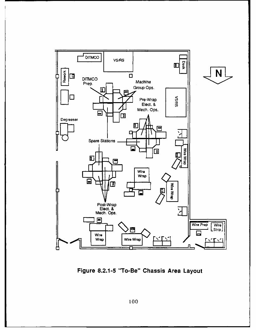
VS/RS
LJ Prep. MachineG roup Ops.
L-- Pre-Wrap <Elect. &
Mech. Ops.
Degreaser
El?
Post-Wrap
Elect. &
Mech. Ops.
Wire Prep 1,1m
Wira
Figure 8.2.1-5 "To-Be" Chassis Area Layout
100

The proposed floor plan provides for an average reduction of flowdistance by 34%. While this reduction is not necessarily a significant cost driverfor evaluating the improved chassis area arrangement, the non-quantifiableimprovements in efficiency, reduction of material movement required by GroupLeaders, and several other factors support this improved layout.
8.2.2 Transformer Area Floor Plan
The transformer area floor plan development required that productionlayouts for all products currently built within the area in 1986 and projectedproduction for 1987 be analyzed. These layouts provided the initial data forestablishing standard hours per operation per part number. This data was thenused to develop a group technology analysis matrix. Data regarding operationsdescriptions was defined along the x-axis, part numbers of assemblies and sub-assemblies were listed along the y-axis, and standard hours were entered atthe appropriate part number/operation intersection.
Production totals were entered for each of the part numbers in the matrixfor 1986 production. A second matrix was used to enter projected productiontotals for 1987. A calculation was then made by multiplying the productiontotals by the operation standard hours for each of the part numbers whichresulted in a second matrix physically as large as the first one but nowrepresenting total standard hours for each unique operation per part number.
Production layouts were subsequently referenced to assist in groupingoperations that were or could be performed at a specific type of workstation,The groupings were then reviewed by personnel within the transformer groupfor accuracy. The matrices were then consolidated into five major categories,which were:
• Machine Group• Winding° Leadsetting* Epoxy operations• Test
The next consolidation of the matrix involved adding up all of the partnumbers for a production total of all transformers manufactured by FM & TS.
Business volume projections were then established for the transformerarea in conjunction with Honeywell's Costing and Forecasting groups. Thenumbers calculated for the 1986 consolidated matrix were then verified usingthe Foreman's Cost Report which lists the total standard hours earned in thetransformer area.
These projections were then analyzed to determine the percentagegrowth for Flight Management as well as Targeting Systems. However, as aresult of meetings with Honeywell's Costing and Forecasting groups, it was
101

determined that the growth for the transformer area should be considered as flatsince transformer production is primarily devoted to on-going program volumesand the development of prototypes for new products.
The actual hours were established using cost variance ratios developedby the FM & TS Cost Accounting department.
The actual number of each type of workstation (based upon headcount)was established by dividing actual hours per type of workstation by 1800 hours.The assumption of 1800 hours per year allows for 80 hours vacation, 80 hoursholiday, 120 hours for lost time (sick, jury, etc.).
After the initial effort to establish the number of workstations required andthe characterization of the operations to be performed at the workstations, anumber of assumptions and criteria were established and weighted as toimportance for developing the transformer area floor plan with respect to workbench surfaces. These included:
1) The assumption that the work area would be designed toaccommodate all of the work projected during a one shiftoperation.
2) Specific areas would be provided to accommodate work loadpeaks as well as expansion for new prototypes and production.
3) Floor space utilization would be minimized so that the footprint ofthe overall transformer area would be flexible enough for animplementation in a joint area defined to house both transformerand chassis operations.
4) Work cells or clusters would be developed to provide a moreorganized area and more direct process flow. The characteristicsof these would be that:
a) Cells were developed for specific processes (i.e., winding,leadset, stator, test, etc.)
b) Orientations would be developed that permit multipleoperations per cell (i.e., winding, leadset, test)
5) Standardized modular work benches would be defined toincrease the flexibility of rearranging operations.
6) Cellular arrangements would be developed taking into accountthe latest developments in electronics manufacturing ergonomicstudies and accommodate economic utilities installation.
7) Areas would be designed which provided for the ability to easilymonitor all of the operations in the transformer work center.
102

After the development of the assumptions and criteria, detailedproduction flows (summarized in Figure 8.2.2-1) were analyzed and used asinput to the overall transformer area layout. This analysis focused on thetransformer production volume (which was described utilizing pareto diagrams)that represented the highest volume transformers so that transport savingswould be maximized. This allowed optimization of all work bench surfaces plusadditional equipment (winders, etc.). The assumptions and criteria developedas a result of the production flow analysis included:
1) Clustering of winding equipment associated with higherproduction volumes.
2) Establishment of leadset clusters to concentrate the use ofcommon equipment.
3) Incorporation of convenience factors in areas involving multipletransport moves between work surfaces and specialized processpoints (e.g., Epoxy room).
4) Consolidation of the overall work area which, while minimizingflow distance, provides sufficient area for expansion in thefollowing three to five year time span.
Storage and material handling equipment requirements were developedto meet the needs of production for the next three to five years as well. Storagemechanisms (such as VS/RS) were based upon the volume of stored materialand its proximity to the point of use. Briefly, one VS/RS was defined asadequate for wire reels used in winding and a second unit was dedicated tostorage of leadsetting tools and work-in-process, and a third unit was definedfor the storage of epoxy room supplies.
Movable cart storage or carried totes were determined to be the mosteffective means of transporting work-in-process and limiting work-in-processstorage. This was primarily due to the low volume of production in thetransformer area and the relatively small footprint occupied by this area.
Possible locations for the placement of the transformer area were thenreviewed and evaluated for optimum placement of that activity within the totalFM & TS production operation. An area was defined by the Honeywell FacilitiesPlanning organization that was adequately sized to accommodate thetransformer operations as designed.
The resulting floor plan developed for the transformer area is presentedin Figure 8.2.2-2 and can be characterized as providing the following features:
1) Transformer area is generally laid out to provide a smooth flowfrom wind to leadset and/or test followed by the necessaryimpregnation and encapsulation operations.
103

((As-Z5)
233W3
LZAD-8Z? ROM(As-IS)
Figure 8.2.2-1 Typical Transformer Production Flow
104

Soda Slant Area
Air Lock / _ _ _ _ _ _ _ _ _ _ _ _ _ _ _ _ _ _ _ _ _ _ _ _ _
Lu IFreezerl Xfmr Teating Area
01
Epoxy<Room 3 E
Lead
Ovens at 11 0with hoo Window ~e t
LeadSet
Oven~~I Oven Desl
S IJ
C Winders
Unrelated Winding Area 6:Operations U
~ [I-r Workben.ch Winder
Figure 8.2.2-2 "To-Be" Transformer Area Layout
105

2) Layout is configured with more than adequate aisle space so thatvariations in process requirements from assembly to assembly donot pose significant flow problems.
3) Winding area is laid out so that machinery with high utilization isgrouped in a centrally located "island".
4) One VS/RS unit is positioned in close proximity to the windingarea to provide wire and coil-form supplies to the winding cell (thisunit could optionally be configured to be restocked from the back,if desired)
5) The second VS/RS is located near the leadset operations toprovide supplies support and work-in-process storage.
6) A third VS/RS is located in the Epoxy Room for supplies storage.
7) The epoxy room is shown as being located outside the current"airlock". Parts are moved to and from this area through a slide upwindow. (Alternately, if the airlock/clean room environment is notrequired, an access doorway could be provided at this location).
8) A small room is provided for "dirty" operations in the transformerarea. Additionally, this room can function as an "airlock" for thetransformer area as an alternative to the existing access ways.
9) Existing soda blast room has been re-oriented to allow animproved layout and placement of the epoxy area.
10) Epoxy room has been re-oriented to provide additional aislespace with a centralized bench area. Curing ovens are groupedalong the walls toward one end of the room and clustered aroundthe bench "island" so that work can be prep'd and moved backand forth between ovens and work surfaces.
11) Provisions have been made to accommodate all existingtransformer test equipment as well as an ATE unit.
The major factors emphasized in the proposed floor plan include moreconsolidated operations, work place arrangements that promote greateroperator interface, and work and materials storage is provided in closeproximity to their point of use.
The proposed floor plan provides for an average reduction of flowdistance by 95% (see Section 8.4 for a more detailed description as to how thispercentage was developed). While this reduction is not necessarily asignificant cost driver for evaluating the improved transformer areaarrangement, the non-quantifiable improvements in efficiency and the
106

reduction of material movement required by Group Leaders and stores
personnel support this improved layout.
8.3 "To-Be" Production/Process Flow
The "To-Be" production/process flow is presented in the followingsections. One of the major improvements in the optimized design of theproduction/process flow for each of the areas is the development of astraightforward production flow that is aligned with the process flow.Additionally, in the transformer area, the consolidation of the geographicallydistinct operations will result in significant production flow improvements.
8.3.1 Chassis Area Production/Process Flow
The chassis area in the "To-Be" configuration integrates the sequentialprocesses necessary to produce a finished chassis for the various militaryprograms so that duplication of stations is unnecessary to ensure uninterruptedproduct flow.
Each wire wrap plate passes through a series of stations to and from wirewrap depending on the necessary preparation or post wrap work. Since noprogram volume is sufficient to fully utilize a given station (except wire wrap),the process orientation allows significant labor consolidation. Similarly, inchassis build-up, tooling and parts are centralized and material stocking can beconcentrated in storage systems (e.g., VS/RS) to save transit, search, andpicking times.
8.3.2 Transformer Area Productlon/Process Flow
A survey of the top eighty percent of transformer assemblies and sub-assemblies produced during 1986 was performed to establish the transportprofile for the area and determine the resources required to move these partsthrough the production process.
An external movement analysis revealed that transport between therespective operational areas consumed an estimated 1474 hours during 1986.This is important in two respects. The consolidation of the separate areas couldpotentially reduce the stockroom allocation to FM & TS. Also, delays inprocessing and the effective application of FM & TS transformer personnel willbe positively impacted as a result of maintaining uninterrupted production flow.
Intra-area movement provides minimal savings. This is a result of therelatively small number of transformer/sub-assembly lots processed. Thecomparison of flow distances within the "As-Is" and "To-Be" layouts resulted in afive percent transport reduction.
Additionally, the project team believes, and current industry experiencebears out, that the combination of consolidating the respective transformer
107

operations and developing ergonomic work cells will result in productivity gainsin excess of ten percent per year.
8.4 "To-Be" Material Flow
The improvements in the "To-Be" material flow are presented in thefollowing paragraphs. In general, a number of characteristics can be statedregarding the improvements in both the chassis and transformer areas. Themost important improvements in the material handling for both of the areasinvolves the methods and equipment used for material and fixturing storage.
8.4.1 "To-Be" Chassis Area Material Flow
The chassis area material flow will be significantly improved through theimplementation of three major types of material handling and storage devices.These are:
Vertical Storage and Retrieval Systems (VS/RS)
Bench-top Rotary Parts Presentation Bins
• Dedicated Material Handling Carts
These three pieces of equipment are described in detail in the followingsubsections.
8.4.1.1 Vertical Storage and Retrieval Systems (VS/RS)
In the current chassis area configuration, over 1,000 cubic feet is devotedto storage of all types, including fixtures, wire wrap plates, queued material,work-in-process, fasteners, wire, repair parts, etc. In gross numbers, over a thirdof material currently stored is related to work-in-process, another third is madeup of DITMCO fixtures, cables, and other related miscellaneous materials, andthe balance is divided between wire wrap materials and supplies.
In the "To-Be" chassis area operations, a majority of all of the material inthese work areas will be stored in Vertical Storage and Retrieval Systems(VS/RS). VS/RS units are automated, micro-processor based storage andretrieval systems which occupy small footprints of space. Items are stored inpans which travel following a vertical enclosed loop track. Pans are brought towork counter height via the shortest route. An operator does not have to bend,search, or grow fatigued looking for an item, therefore improving productivity.
These systems will reduce the floor space utilized for storage significantlyand consolidate material into specific areas adjacent to the materials' points ofuse which reduces the material movement travel time. It will also assist groupleaders and operators by significantly reducing the time associated withlocating materials.
108

Figure 8.4.1.1-1 presents the reduction in storage volumes that can beachieved with the use of two Vertical Storage and Retrieval Systems. It isproposed that one VS/RS be oriented near the DITMCO tester to supplyproduction parts and store work-in-process. The second VS/RS will be utilizedfor wire wrap related parts, fixtures, and supplies. Storage of DITMCO cableswill be in cabinets until a feasible set-up arrangement can be developed fortheir storage by some other means.
Another significant improvement associated with the implementation ofthe VS/RS units is the purchase of a computer-driven material locating systemfor each of the VS/RS units. While many users require a simple "go to pan"operation, to take full advantage of these units, a storage and retrieval locatingsystem is proposed. This will serve to eliminate excessive time required tosearch for the appropriate materials and more optimized utilization of thestorage devices.
Figure 8.4.1.1-2 presents an elementary software diagram for a basic'storage management system. This type of system consists of five majormodules, which are described in the following paragraphs.
Storage Management Module
The Storage Management Module (SMM) should manage the StorageDatabase, Part Number Database, and Storage Arrangement Table. The SMMshould create inventory records and provide keyed access to the StorageDatabase, Part Number Database, and the Storage Arrangement Table. TheStorage Database should contain the following elements:
• Location (shelf number)
* Part Number (multiple part numbers may be stored on same shelf)
The Part Number Database should contain:
Part number (either for a specific assembly or sub-assembly,fixturing, cables, wire wrap plates, etc.)
• Location (for known stored parts or fixtures)• Part number size attributes (for entered part numbers)
The Storage Arrangement Table should contain:
• Location* Size attributes
System Interface Module
The System Interface Module (SIM) should be the operator interfacemodule that services the PC keyboard and display. SIM should manage
109

P, In o I0) Ln W)I
40 0 '0
(0c (n I
0 it
01 Lf 0 0)
0 In toI
(00
LUw
LU LU0 x
0 In a In
00
LLLU
0zx 67
LU
oo ton
014 0 0
LU
01 t0
0N (b N
o0OD Ui
0 C*, 0. C
0 N 0 N 0 N
0 - 0 LU L
Figure 8.4.1.1-1 Chassis Area Storage Volumes
110
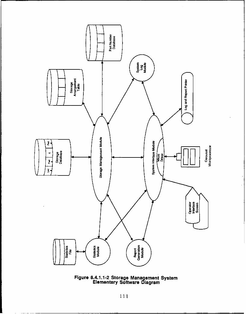
0.
-, 0
oCu-
coEu
Figure 8.4.1.1-2 Storage Management System
Elementary Software Diagram

operator inquiry functions, file utilities, report generation selection, and accessto system utilities. SIM should produce the following on-line query screens:
* Part number in location* Size attributes of part number* Size attributes of location* Statistics summary
System Log Module
The System Log Module (SLM) should maintain a disk file that recordscritical system activity and error conditions for later processing by the SIM reportgeneration routines. All SLM entries should be time-stamped and identified bythe originating module. Events logged by SLM should include:
• Put away errors• Part number location errors* Operating system error codes returned to programs* Disk faults
Statistics Module
The statistics module should keep track of performance information of theput away system.
Report Generation Module
The Report Generation Module should be a collection of small reportgenerating programs that produce management summary reports.
The implementation of this system as well as the implementation of theFactory Data Collection System and the HMS/BOS system should greatlyimprove the tracking of material and work-in-process in the chassis area.
8.4.1.2 Bench-top Rotary Parts Presentation Bins
An aspect of the chassis operations reviewed by the Tech Mod projectteam that contributes to material handling expense is the numerous small partsutilized in chassis assemblies and sub-assemblies. These parts are stored inbin trays located to one side of the chassis area.
As jobs are set up at a bench location, parts (in the trays) are transportedto the designated location by a group leader or the operator. Under the revisedlayout, these parts would be located at a specific workstation and the accessand presentation would be part of a rotary parts storage system consisting ofmany segmented bins.
112

These bins are motor-driven and allow an operator to advance aselected part into view by depressing a remote footswitch or control panelbutton. One of these bins provides spaces for as many as 120 different smallparts such as screws, nuts, resistors, capacitors, connector pins, etc.
By grouping parts unique to various assemblies on different levels,increased efficiencies can be achieved through the elimination of searching formaterial in remote parts bins. Replenishment is similarly augmented.
This equipment could be customized in the future by the addition ofposition sensing equipment and a locator control scheme which would allowautomatic sequencing of parts bins. This set-up should be considered when atie-in with a workcenter controller is developed.
8.4.1.3 Dedicated Material Handling Carts
In the proposed plan, material would be transported throughout the workarea on carts with a very limited number of shelves and closeable/lockabledoors. The major premise behind this is to only have material on the shop floorthat is being worked on and all other materials stored. Since work-in-processstorage could potentially occupy approximately 200 cubic feet in the VerticalStorage and Retrieval System, improved material handling disciplines must beestablished.
The benefit of limiting work-in-process storage to carts (with work-in-process in the VS/RS stored due to lack of materials to complete the job or ascompleted sub-assemblies) is that what is actually "in-process" will be readilyapparent. The Japanese liken this method to that of draining a pond to makethe bottom a smooth surface. As water is taken away, the largest rocks appearfirst. As each rock (or unnecessarily stored item) is removed, the pond is furtherdrained until all of the rocks are removed.
By not providing unlimited storage areas, problems related to timelydelivery of kitted parts, etc. will surface and be more effectively dealt with.
8.4.2 "To-Be" Transformer Area Material Flow
The transformer area material flow will be significantly improved throughthe implementation of Vertical Storage and Retrieval Systems. Currently, thestorage of all materials in the transformer area is in a variety of cabinetsdistributed throughout operational areas. The greatest amount of cabinet spaceis assigned to store wire and other winding related materials. In other areas,there are seventeen large cabinets and over twenty "under bench top" shelvesused to store assembly, leadsetting, and epoxy materials. In total, there areforty-eight individual storage locations totaling over 940 cubic feet.
113

By establishing three VS/RS units, one each in winding, leadset, andepoxy, this storage space can be centralized for material presently spreadaround the areas. Furthermore, easier storage and retrieval will be madepossible via the automatic locator system described in the previous "To-Be"Chassis Area Material Flow section.
The VS/RS units will increase floor space utilization by concentrating agreater amount of cubic storage in one area through the use of three additionalfeet in height. By bringing material to a usable height for placement/retrieval,spaces which are normally wasted in cabinets (near the floor or above anoperator's head) are reclaimed for use. A ten foot high VS/RS can makeavailable 350 cubic feet of storage in a space that tall cabinets can only provide190 cubic feet, an increase of 84%. Additionally, travel distance with a VS/RS iscut to one-quarter to access the equivalent volume.
The proposed integrated and consolidated transformer area will containthree VS/RS units. These will serve the main activity areas of wind, leadset,and epoxy. This will provide supplies closely coupled to the point of use. Also,since winding takes up all of one VS/RS unit, the proximity of the second unitwill permit any excess storage to be placed in the leadset VS/RS.
As in the case of the chassis area VS/RS (described in Section 8.4.1.1),this equipment is capable of integration into the overall informationmanagement system.
8.5 "To-Be" Information Flow
The most significant improvements in the chassis and transformer areainformation flow will be achieved with the introduction of the HMS/BOS systemcurrently being modified for use at the St. Louis Park facility. While on aconceptual level this system performs all of the same processes as the GAPOSsystem, the increase in functionality is significant. Because the two systems aresimilar in the types of functions they will be performing and the final definition ofthe system has yet to be implemented, the focus of this section will be primarilyon the introduction of the Factory Data Collection system and the improvementsoutlined in this report that can be even further upgraded due to their selectionfor interfacing with a work center controller.
The Factory Data Collection (FDC) system has been developed as ameans of automatically recording hours an employee expends on a specificoperation/part number. This provides important information to FM & TSmanagement both for accounting purposes as well as monitoring thepercentage of completion of a specific part being built. It is envisioned that inthe future, the FDC system will be expanded to provide location tracking ofwork-in-process as well.
It is envisioned that at some point in the future the Vertical Storage andRetrieval Locator System will be interface to HMS/BOS, either directly (which is
114

not recommended) or through another system such as the Factory DataCollection System. This would provide a more integrated material trackingsystem.
One other program which is currently under evaluation for Honeywell'sMAvD is the introduction of a "factoryvision" system (ITM Project 32) which willpresent production layouts and other production related information to each ofthe operators on the shop floor. This type of system, interfaced with a workcenter controller would raise Honeywell's operations to the most advanced,state-of-the-art achievable with the computing technology available today.
8.6 "To-Be" Equipment
The following subsections describe the equipment proposec. forimplementation in the FM & TS chassis and transformer areas. This equipmentsignificantly improves the operations in these areas and provides for theoperations of these areas on a higher level of automation with, in some cases,the upward compatibility to an advanced work center controller beingconsidered for future implementation.
8.6.1 Chassis Area Equipment Improvements/Upgrades
There are a number of equipment improvements or upgrades that arepresented in the "To-Be" operations in the chassis area that affect the overallwork area design. This equipment includes:
• Vertical Storage and Retrieval Units* Rotary Parts Presentation Equipment* Material Handling Carts
8.6.2 Transformer Area Equipment Improvements/Upgrades
There are a number of equipment improvements or upgrades that arepresented in the "To-Be" operations in the transformer area that affect the workarea design. These improvements include:
* Modular, ergonomic workstations• Vertical Storage and Retrieval Units
8.6.3 Transformer Ergonomic Modular Workstations
Considerable interest has been generated in the electronicmanufacturing community over the past few years over improving productivity inthe workplace. The FM & TS organization has been evaluating andincorporating some newer, modular workstations into its operations to improveproductivity through better arrangement and efficiency at the work surface.
115

The Tech Mod project team has reviewed several styles of workstationsin an effort to determine the most suitable configuration and arrangement whichwill enhance productivity. The team was assisted in this effort by the findings ofthe U. S. Navy Electronics Manufacturing Productivity Facility (EMPF) in theirstudy of several types of workstations.
The EMPF, in a study that included both male and female subjectsinvolved in electronic assembly activities, concluded that the most productiveenvironment for workers occurs when the operator is placed in a modular workspace with minimal opportunity for visual distraction. The study found that theelimination of "eye contact" in the work environment contributed 22% to theoverall productivity of subjects involved in electronic assembly activities, thusallowing concentration on assigned tasks.
The Tech Mod team also reviewed various workstation configurationswhich could potentially take advantage of the EMPF study results. Two mainarrangements were derived that allowed both efficient work flow andeconomical arrangement:
• Work Cells
Bench Clusters
The work cell may consist of two or three benches arranged to provide a"U" shaped flow as products are passed through a series of steps in the cell.This arrangement generally conserves floor space and shortens external flowlines. In one version of the chassis area floor plan, this configuration resulted ina flow reduction of over fifty percent when compared to the "As-Is" condition.
The second configuration is a four bench "cluster," which while requiringexternal circulation to move work from station to station, benefits from requiringa singular utility drop thereby allowing economical installation and relocation.This arrangement allows what FM & TS Production management feels arebeneficial operator groupings to accomplish similar or sequence related tasks.Utilizing this type of workstation grouping resulted in a reduction of thirty-fourpercent in flow distances for the chassis area and is contained in the floor planexhibits presented earlier for both that area and the transformer area.
The Tech Mod team also reviewed bench styles and construction detailsfrom several manufacturers. While most bench manufacturers employcomponents formed from cold-rolled steel tubing, some utilize aluminum alloymaterials which are more than durable enough for the types of activities andweights encountered in electronic assembly, and which offer attractive costsavings in implementation.
116

SECTION 9
SYSTEM/EQUIPMENT/MACHINING SPECIFICATIONS
The following sections present the detailed specifications that weredeveloped as a result of the analysis and design performed for two areas withinHoneywell's FM & TS operations under ITM Project 88. The first sectionprovides system and equipment specifications for the Chassis area and thesecond section provides system and equipment specifications for theTransformer area.
9.1 Chassis Area Specifications
The chassis area specifications have been developed for materialhandling and automated storage and retrieval equipment, including:
Vertical Storage and Retrieval Units
Computerized Putaway System
Bench Top Parts Presentation Bins
Secure Material Handling Carts
The specifications for this equipment are presented in the followingparagraphs.
Vertical Storage and Retrieval System (VS/RS)
Dimensions: 7' wide x 10' long x 125" high
Counter: 40" high, static controlled
Shelves: 12 (min.)
Pan Pitch: 12"
Pan Depth: 18"
Pan Load Capacity: 500 lbs.
Machine Capacity: 10,000 lbs.
Interface: RS232C
Controls: Supervisors panel with keylock switch, rotary control andposition display
Electrical: 230 VAC, 30 amp, single phase
117

Computerized Putaway System Specification
The following specification is provided primarily as a preliminaryspecification and may be modified to meet the specific needs of each individualVS/RS.
Hardware: Personal Computer with internal hard diskSystem PrinterSystem RS232C Interface CableOptional bar code reader
The system hardware interconnections should also allow fornetworking of PC's. This will allow for networking diskless PC'sfor complete carousel storage network.
Software: The system software elementary diagram is pictorially describedin Figure 9.1-1. Descriptions of each of the databases andmodules are provided below.
1) Storage Management Module
The Storage Management Module (SMM) should manage theStorage Database, Part Number Database, and StorageArrangement Table. The SMM should create inventory recordsand provide keyed access to the Storage Database, Part NumberDatabase, and the Storage Arrangement Table.
The Storage Database should contain the following elements:
Location (shelf number)Part Number (multiple part numbers may be stored on sameshelf)
The Part Number Database should contain:
Part number (either for a specific assembly or sub-assembly,fixturing, cables, wire wrap plates, etc.)Location (for known stored parts or fixtures)Part number size attributes (for entered part numbers)
The Storage Arrangement Table should contain:
LocationSize attributes
2) System interface Module
The System Interface Module (SIM) should be the operatorinterface module that services the PC keyboard and display. SIMshould manage operator inquiry functions, file utilities, reportgeneration selection, and access to system utilities. SIM shouldproduce the following on-line query screens:
Part number in locationSize attributes of part numberSize attributes of locationStatistics summary
118

EE
C,,
- CU
CL
a U.ii
Figure 9.1-1 Storage Management System
Elementary %ofware Diagram
119

3) System Log Module
SLM should maintain a disk file that records critical system activityand error conditions for later processing by the SIM reportgeneration routines. All SLM entries should be time-stampedand identified by the originating module. Events logged by SLMshould include:
Putaway errorsPart number location errorsOperating system error codes returned to programsDisk faults
4) Statistics Module
The statistics module should keep track of performanceinformation of the putaway system.
5) Report Generation Module
This module should be a collection of small report generatingprograms that produce management summary reports.
Bench Top Parts Presentation Bins
(Rotary Component Dispensers)
Dimensions: 20.5" high x 24" wide x 17.5" deep
Trays: 6
Bins: 20 per tray
Cycle Time: 1 second (approx.)
Control: Panel or remote footswitch
Power: 115VAC, 60Hz
Material Handling Carts
Dimensions: 36* long x 24" wide x 30" high
Shelves: 2 shelves with retainer lip, ESD mats, drag chain
Capacity: 100 lbs.
Casters: 3" -4", rubber, brakes
120

9.2 Transformer Area Specifications
The transformer area specifications have been developed for the ITMProject 88 "To-Be" operations within FM & TS. These include:
* Vertical Storage and Retrieval Units
* Computerized Putaway System
* Ergonomic, Modular Work Benches
The specifications for this equipment are presented in the followingparagraphs.
Vertical Storage and Retrieval System (VS/RS)
See Section 9.1 for a complete description of this item.
Computerized Putaway System Specification
See Section 9.1 for a complete description of this item.
Modular Work Benches
Dimensions: 72" long x 36" wide x 30" high. (Optionally, height maybe variable but this requirement limits number ofvendors).
Work Surface: ESD controlled with grounding attachments.
Shelf space: Adjustable footrest shelf. (This may negate therequirement for a variable height work surface).
Metal Instrument Shelf with back panel for mountingcolor coded cups for fastening hardware. 15" deep x 72"long x 24" high.
Load balancing bar mounted minimum 36" aboveworksurface.
Drawer space: Four drawered unit with master-keyed lock that locks alldrawers.
Electrical Requirements: Duplex outlets (110 AC) with raceway (either mountedalong work surface or shelf).
Pneumatic Requirements: Minimum 3/4" air line with two outlets and standard quick-disconnect couplings.
Lighting: Dual fluorescent tubes in overhead canopy with diffuser.
121

SECTION 10
TOOLING
As a result of the nature of the design and development efforts (improvedmaterial handling), there is no unique tooling required for ITM Project 88.
122

SECTION 11
VENDOR/INDUSTRY ANALYSIS/FINDINGS
The project objectives which dictated realistic cost-payback relationshipsultimately caused the review of a condensed group of material handlingequipment vendors. Some equipment had been previously reviewed by FM &TS personnel so that the preliminary search and selection process wasbypassed in the interest of eliminating duplication of effort.
Since the ITM Project 88 review of the chassis and transformer areascentered on material handling improvements and equipment upgrades, these!ection process focused on the following areas:
* Vertical Storage and Retrieval Systems• Bench Top Rotary Presentation Bins• Dedicated Material Handling Carts• Transformer Area Workstations
Vertical Storage and Retrieval Systems
Several established vendors were contacted and reviewed forequipment suitability. Principal among these were White, J. Webb, and Kardex.The FM & TS organization has had previous experience with the VS/RSequipment manufactured by Kardex, and has found the capacity and servicelevel satisfactory.
A primary requirement in the transformer area was the physical capacityto support dozens of reels of wire used in winding magnetics. Both Kardex andWhite had units with capabilities in this area.
The chassis area requires deeper pans to hold tooling plates and variousfixtures necessitating a VS/RS unit similar to those specifications exhibited bythe White equipment.
All manufacturers were surveyed for the ability to provide standardizedsoftware systems to automate parts picking and putaway as well as storagespace optimization. The desire to avoid "customized" control software wascommunicated to vendors quoting on FM & TS requirements primarily to avoidcontinued maintenance of a non-standard package.
The need for a more optimized storage system in the transformer areawas identified very early in the Phase 1 activity of the ITM program. Therefore,Production Engineering began an immediate search for a possible vendor. Theequipment which was determined to be best suited for the application was theKardex Industriever 6000. Two units intended specifically for use in thetransformer area were ordered in January, 1986. However, because of spacelimitations and management decisions delaying the consolidation of the three
123
transformer areas these units have not been installed. Since Vendor pricingwas reasonably competitive for this type of equipment, in the interest of inter-department uniformity, it is intended that Kardex units will be purchased for thechassis area and that the computerized putaway system also be purchasedfrom the same vendor.
Bench Top Rotary Presentation Bins
While several workstation suppliers such as Advance, Kinetechnics, IsleIndustries, etc. have some form of rotary parts presentation, few firms offer asystem with the capability of placing dozens of parts within convenient reach ofan operator seated at a workbench. Since a multitude of small parts are used inFM & TS (especially in the chassis area), a system was needed which wouldprovide this function. Ideally, a miniaturized VS/RS would be the perfectsolution for small parts presentation, but a device capable of handling hundredsof small parts in this manner is not presently available.
A powered rotary parts unit is available from Assembly and ProductionAids which exhibits the desired features, but is only capable of holding 120different small parts. This basically permits about 360 small parts to be withineasy reach of an operator if three units are used. This will generally satisfyrequirements at any given workstation within the chassis or transformer area.
Dedicated Material Handling Carts
Of all equipment specified for the chassis area, carts are possibly themost generic. Numerous vendors provide a suitable mobile unit. Capacitiesappropriate to the task of moving work around the chassis area aremanufactured by such companies as Metropolitan Wire Goods, Hodges, GamcoIndustries, and several others.
Specifications generally cover wheel types, construction, and maximumcapacities expected. A review of work flowing through the chassis areaindicates that the maximum weight of transported parts, assemblies, or kits fallsin the range of 50 to 75 pounds, thus allowing carts of a wide range of structuraltypes to be used.
It is anticipated that FM & TS operations management will review theoutlined requirements and match that with a unit generally used in the area atpresent.
Transformer Area Workstations
Known vendors such as Herman Miller, Straether, Advance, Ergotech,etc. provide a wide range of competitively priced equipment. Some vendorshave unique features, which in specialized applications might dictate selection,but the stations proposed for Project 88 are readily available in a configurationmeeting the current area specifications. Since a few workstations have been
124

purchased within the past year (not as a part of this project) from Herman Millerto be used within FM&TS, it was decided to specify Herman Miller equipment forcontinuity of style unless a strong case can be made for a special applicationprior to implementation. As a result, the average cost of the previouslypurchased stations was used for computation of factory costs.
125

SECTION 12
EQUIPMENT/MACHINERY ALTERNATIVES
Most of the equipment alternatives in ITM Project 88 are vendor-dependent rather than actual alternative technologies. The followingparagraphs describe the alternatives to the equipments selected for ITM Project88 in the event that the primary choice becomes unavailable.
Vertical Storage and Retrieval Systems
If the specified Kardex VS/RS units become unavailable several suitablealternatives exist. The primary alternative is a Model TB-1261 from WhiteStorage & Retrieval Systems. The cost of the alternative hardware iscomparable to the Kardex units, however the software is somewhat higherpriced (approximately $15,000 more).
Bench Top Rotary Presentation Bins
An alternative to the proposed Rotary Bins would be fixed bins on racks(similar to the "As-Is" method except the bins would be at each workstation).This would be an improvement over the present method but would besomewhat less efficient than the proposed system.
Dedicated Material Handling Carts
Of all equipment specified for the chassis area, carts are possibly themost generic. Since the initial choice of vendor will depend upon thepreferences of operations management to match units generally used in thearea at present and numerous vendors provide a suitable mobile unit, makinguse of one or more of the alternate vendors would have little or no impact on theproject implementation.
Workstations
The workstation vendor chosen (Herman Miller) is one of many whichmeet the requirements. There are several vendors whose equipment iscomparably priced. Therefore, making use of one or more of the alternatevendors would have little or no impact on the project implementation.
126

SECTION 13
MIS REQUIREMENTS/IMPROVEMENTS
The most significant improvements in the chassis and transformer area inrespect to the Honeywell MIS department will be achieved with the introductionof the HMS/BOS system currently being modified for use at the St. Louis Parkfacility. HMS is a modular system comprised of the following modules:
* Master Production Scheduling (MPS)* Inventory Records Management (IRM)• Manufacturing Data Control (MDC)* Material Requirements Planning (MRP)• Capacity Requirements Planning (CRP)* Purchase Material Control (PMC)* Production Cost Accounting (PCA)
In addition to HMS, Honeywell is also implementing a process layout systemwhich includes the Process Management System (PMS) and the Factory DataCollection (FDC) System.
The Factory Data Collection (FDC) system has been developed as ameans of automatically recording hours an employee expends on a specificoperation/part number. This provides important information to FM &. TSmanagement both for accounting purposes as well as monitoring thepercentage of completion of a specific part being built. It is envisioned that inthe future, the FDC system will be expanded to provide input to a system forlocation tracking of work-in-process as well.
Honeywell is also developing the specifications for a Work CenterManager System (WCM). While these specifications are still in thedevelopment phase, the improvements described in this document take intoaccount the eventual implementation of these ufforts and have been designedfor future interface to a Work Center Manager System. The followingparagraphs describe the basic functionality required of the Work CenterManager System.
A Work Center Manager System is typically a major piece of ahierarchically structured computerized factory control system. Residing at ahigher hierarchical level than the WCM are the corporate systems and the MRPand MRP II systems such as HMS/BOS. Because MRP II systems are batchprocessing operations, the Work Center Manager has been assigned theresponsibilities of direct, real time control of the factory floor. In this role, thesystem is responsible for short term, global scheduling tasks (during theoperating day) and coordinating the inter-cell operations (such as materialhandling "hand-offs") that reside below it in the controls hierarchy.
It is also envisioned that the Work Center Manager will distributegraphics and textual process data to workstations and will maintain a process
127

data library which will be accessed by various pieces of the process controlhierarchy (such as PLC's and other automated equipment).
It is envisioned that at some point in the future the Vertical Storage andRetrieval Putaway or Locator System will be interfaced to HMS/BOS, eitherdirectly or through another system such as the Factory Data Collection Systemto provide a more integrated material tracking system. It is not recommendedthat the Locator or Putaway System be interfaced directly to HMS/BOS due tothe nature of a hierarchically controlled manufacturing operation. Systems suchas HMS are typically batch-oriented systems and do not allow for theprocessing of real-time, lower level activities such as material/location tracking.It is therefore recommended that the Locator or Putaway System be interfacedthrough the Factory Data Collection System or the Work Center Manager.
One other program which is currently under evaluation for Honeywell'sMAvD in conjunction with the Work Center Manager System is the introductionof ITM Project 32, which will present production layouts and other productionrelated information to each of the operators on the shop floor. This type ofsystem, interfaced with the Work Center Manager System would raiseHoneywell's operations to the most advanced, state-of-the-art achievable withthe computing technology available today.
128

SECTION 14
COST BENEFIT ANALYSIS AND PROCEDURE
In analyzing ITM Project 88, attention was focused on the methods andprocesses utilized in the FM & TS chassis and transformer areas. Activitiesreviewed in the transformer area included winding, leadset, testing,impregnating, and marking. In the chassis area, operations studied includedmachine operations, mechanical assembly, electrical assembly, wire wrapping,and continuity testing (DITMCO).
In the initial stages of the project, several areas were identified as costdrivers and reviewed for possible savings using the methodology shown in theprocess diagram of Figure 14.0-1. This also required the identification ofproductivity and quality factors as a means of evaluating the cost drivers.
14.1 Productivity and Quality Factors
The productivity and quality factors that exhibited the greatest potentialfor benefit were:
• Hours Spent Moving Material• Operator Productivity• Group Leader Time Expenditures• Production Controller Time Expenditures
Areas identified from the contract ledger data and foreman's cost controlreports which did not result in significant benefit were:
* Scrap• Rework
Because of the diversity of product and/or the low annual volume levels,both rework and scrap were considered to be at relatively low levels in the ITMProject 88 areas.
The following paragraphs describe the major productivity and quality
factors in the transformer and chassis areas for ITM Project 88.
Standard Hours
Product standard hours were derived from internal Honeywelldocumentation and extended for 1986 production volumes to establish "As-Is"conditions. These totals were compared to those logged in the Foreman's CostControl report for 1986 as a validation measure.
Specific operation measurements were performed by IndustrialEngineering to form a baseline for "To-Be" operations in group leader and
129

- C
a~~ a clLc
~oC,, 0 cc
cc Cl) <l c/0 M cl)
w ~ ~ ~ W3c.L
U,
0 0zc >_ _ _ _ _ 0 3.
_ _ _ _ _ _ _CC_ _U_
Fiur 140- Cos Beei nlsi ehdlgZ Z ccUj130

production control activities. Estimates of most "To-Be" operational standardswere derived from study data gathered by the project team.
Evaluation of savings utilizing modular workstations was supported bydata obtained in a study performed by the U.S. Navy Electronic ManufacturingProduction Facility (EMPF), China Lake, CA and generally substantiated byproductivity increases experienced in the electronics industry.
Actual Hours
In determining savings for the chassis and transformer areas, actualoperating ratios derived from Foreman's Cost Control reports were utilized. Allstandard hours were "normalized" to actual hours to perform "As-Is" versus "To-Be" comparisons on an area-by-area basis. This method is then able to takeinto account all operational factors not normally included in standards.
Assumptions
All calculations are tabulated for ten yearly periods by quarter, beginningwith the implementation point. Generally, implementation commences during1988.
Production rate increase/decreases are calculated based on the ten yearmarketing forecast for FM & TS revenue projected from factory production. Thisapproach removes sources of revenue not directly attributable to productsmanufactured in the FM & TS production facilities addressed in the Tech ModITM Project 88.
14.2 ITM Project 88 Cost Drivers
The following paragraphs describe the cost drivers for ITM Project 88.
Chassis Transport Direct Labor Savings
The measured average distance traveled per job within the "As-Is" areais 187 feet. The average "To-Be" distance traveled per job is estimated at 88feet (47% reduction). Movement was then estimated at 1.5 feet per second.
The percentage escalation in annual hours for the chassis area wasderived from 1986 usage data multiplied by the annual estimated growth in FM& TS revenue (1987-1998). Hourly rates, burden, and escalation rates wereobtained from Honeywell's Cost Estimating.
Transformer Transport Direct Labor Savings
The measured intra-area transport within the "As-Is" locations is anaverage of 221 feet. The "To-Be" intra-area distance was measured at an
131

average of 210 feet. Lot count was derived from 1986 data. Additionally,
movement was estimated at 1.5 feet per second.
Transformer Workstations Direct Labor Savings
"As-Is" total hours were taken from the 1986 production matrix. "To-Be"hours were calculated for bench related work (leadset) only (53 perLent) andexcluding wind, test, and epoxy operations. The productivity factor from theEMPF study (22 percent) was then multiplied by the leadset percentage.
No percentage escalation in transformer annual hours is included due toa management operational decision for the area dictating an essentially levelbuild schedule. Hourly rates, burden, and escalation rates were obtained fromHoneywell's Cost Estimating department.
Transformer Group Leader Labor Savings
Group Leader savings were based on one group leader expending 24.6percent of time on material related issues in the "As-Is" condition. The "To-Be"condition anticipates a reduction of group leader material related time to tenpercent of total annual hours after installation of the material handling andtracking system. It is also assumed that there will be no increase in groupleader headcount over the span of the project.
Chassis Group Leader Labor Savings
Group Leader savings were based on one group leader expending 28.2percent of time on material related issues in the "As-Is" condition. The "To-Be"condition anticipates a reduction of group leader material related time to tenpercent of total annual hours after installation of the material handling andtracking system. It is also assumed that there will be no increase in groupleader headcount over the span of the project.
Group Leader available time is estimated at 1800 hours/year. Thesavings assumes implementation in the fourth quarter of 1988. Hourly rates,burden, and escalation rates were obtained from Honeywell's Cost Estimatingdepartment.
Production Control Labor Savings
Production Control savings were based on the equivalent of oneproduction control person expending 25 percent of total time on material relatedissues in the "As-Is" condition. The "To-Be" condition anticipates a reduction ofproduction control material related time to ten percent of total annual hours afterinstallation of the material handling and tracking system.
It was assumed that there would be no Production Control headcountincrease over the duration of the project. Calculations utilized 1800 hours/year
132

as total available time. Hourly rates, burden, and escalation rates wereobtained from Honeywell's Cost Estimating department.
14.3 Capital and Expense
The capital, recurrng and non-recurring expenses for Project 88 are
shown in Figure 14.3-1.
14.4 Project Savings and Cash Flows
The savings to be realized in this project exceeds Honeywell's MilitaryAvionics Division hurdle rate. The Project's cash flows are shown in Figure14.4-1 with the assumption that capital will be available per the implementationplan.
133

PROJECT 88 EXPENDITURE SUMMARY
GROSS CAPITALIZATION GROSS YEARCOST YEAR COST EXPENSED
CAPITAL COSTS EXPENSE COST
MACHINERY COST NON-RECURRING EXPENSES
AREA PREP. (HI) $117,407 1988 AREA PREPARATION (HI)VS/RS UNITS $106,628 1988 $66,900 1988
SUB-TOTAL $224,035 1988 SUB-TOTAL $66,900
FURNITURE COST TRAINING81,300 1988
MATERIAL CARTS $9.852 1988 $1,600 1989WORKSTATIONS $34,770 1988
SUB-TOTAL $2.900SUB-TOTAL $44,622 1988
PROCESS MOOIFICATIONCOMPUTER COST $3,900 1988
= 1600 1989MATlL LOCATOR SYS $26,657 1988
SUB-TOTAL $5,500SUB-TOTAL $26,657 1988
VSIRS PROGRAMMING$29S.314 1988 $1,300 1988
$800 1989TOTAL CAPITAL COST $295.314
SUB-TOTAL $2.100
873,400 1988$4000 1989
TOTAL NON-RECURRING $77,400COST
TOTAL CAPITAL AND $372,714NON-RECURRING
RECURRING EXPENSESANNUAL MAINTAINANCE $5,l0
Figure 14.3-1 Project 88 Expenditure Schedule
134

00
40 N'4'
N
40N;4'
4*
(0 -'
44
N'
:2 2 .- 0)0, -0 'a (
40 0
0 0- C Cma. 401 e; Nq
oO 300 40
46 4 ; M ,
40 q
40 'a 4' 440;
a 3k
a ND
0'A
Figure 14.4-1 Project 88 Cash Flows
135

SECTION 15
IMPLEMENTATION PLAN
The implementation plan for ITM Project 88 initially developed out of anearlier review of factory requirements and the recognition of a need to initiatemodernization activities within the FM & TS Production area. ITM Project 88concentrated attention on improvements which could be made in niateii.Jhandling methods and area relayout within the FM & TS Chassis andTransformer Production areas.
Since the equipment proposed for acquisition is readily available fromseveral vendors, implementation can be accomplished within a relatively shortperiod (under six months) and will be paced by the availability of physicalfacilities.
15.1 Implementation Plan Activities
Implementation of ITM Project 88 activities is depicted in the PlanSchedule (Figure 15.1-1). Since the equipment can be accommodated withinthe existing production area, acquisition can commence upon receipt of projectapproval. The improvements scheduled for ITM Project 88 include thefollowing:
* Relayout and relocation of Chassis and Transformer Areas• Installation of Vertical Storage and Retrieval Systems• Implementation of VS/RS Putaway/Locator System* Installation of Bench Top Presentation Bins* Purchase and use of Dedicated Material Handling Carts* Restructuring of group leader and production controller activities
The availability of factory floor space will allow installation of theimproved product flows as well as the planned operational parameters for theimproved equipment.
ITM Project 88 implementation will take place in three basic phases:
Phase Activity
I Program PlanningII Acquisition, Installation, and TrainingIll Operation and Validation
136

0
CO
a) "
:EE
0 cc~
i1
o 4 .
C' I " .0
-,,, ,
I>
00 L EL a
00¢
9 ' ---
Figur 1 e 8
0037
a) 9 9
7o 9
a) 0
113

15.2 Phase I - Program Planning
During this phase, all documentation relating to purchasing of theequipment and/or software should be finalized. This will permit immediateinitiation of purchase orders upon project approval.
15.3 Phase II - Acquisition, Installation, and Training
Upon placement of orders, physical preparations can commence.
Sufficient time will be available to stabilize equipment locations which fitinto revised areas and product flows and make adjustments in processes andmethods which will more effectively integrate the new equipment.
Prior to installation at Honeywell, all software systems will be validated atthe respective vendors. All parameters which are customized to Honeywell'srequirements will be functionally demonstrated before delivery.
15.4 Phase III - Implementation and Validation
Depending on the respective equipment, implementation is projected tooccur either in the third or fourth quarter of 1988. It is assumed that allnecessary documentation changes associated with the scheduled build ofprincipal models will be completed prior to the start of this phase. This willpermit an accurate measurement of the benefits of each improvement andvalidation of the project savings.
Since the implementation of nearly all the modifications in ITM Project 88impact direct labor performance, the principal validation in the "To-Be"organization will be derived from the "Foreman's Cost Control" records on amonth-by-month basis. Additionally, time studies evaluating selected standardsmay be conducted to validate projected values. Revised paybacks can then beestimated with the resulting "live" data.
138

SECTION 16
PROBLEMS ENCOUNTERED AND HOW RESOLVED
Problem: Availability of space for ATE Central facility to be located with FM &TS area upon project implAmentation.
Solution: Chassis area was combined with the relocated transformer facilityinside the clean room area.
Problem: Translating various FSO marketing projections of future revenueinto growth figures applicable to FM & TS.
Solution: Figures were ultimately subjected to a process of review andscrutiny to ascertain those actually applicable to FM & TSProduction.
Problem: Preliminary designs, while technically correct, did not reflect FM &TS preferred operational mode.
Solution: Subsequent designs were modified in a "working meeting"atmosphere so as to contain a maximum number of featuresdesired by the operational personnel who would be implementingand using them.
Problem: Large quantities of parts related data presented a significant datareduction task to derive usable summaries.
Solution: Large data matrices were developed to integrate productdescription, operation, standards, and quantity data. This enabledaccurate and comprehensive summaries to be developed.
Problem: Multiple locations were potentially available for future operationsnecessitating significant relayout efforts.
Solution: Area elements were entered into CAD database allowing easierupdate and relayout as revisions and relocations were proposed.
Problem: Significant amounts of tabular data developed and continuallymodified to reflect current rates, times, and quantities. This waspotentially a large clerical task.
139

Solution: Data was linked and manipulated via powerful spreadsheetprograms thus minimizing clerical effort.
140

SECTION 17
AREA FOR FUTURE CONCERNS/DEVELOPMENT
Future Concerns
As implementation of Factory Data Collection (FDC) is considered andinitiated, attention should be given to providing only those data elementswhich are necessary for specific area functions to be available in thatarea. This will reduce the "clutter" of data which could potentially impedethe performance of the system. This, essentially, is the essence ofhierarchically linking work centers, cells, stations, etc. so that each nodehas the key resources necessary to accomplish its task.
Equipment has been proposed for this project in which capabilities existfor future inclusion in local factory networks. This will facilitate futurefactory modernization. It is important that any automated equipmentunder consideration be viewed as necessarily including this capability.
Future Development
Any replacement equipment should have the capability to interface ornetwork so that data can be exchanged and configuration can becontrolled.
FM & TS should continue to advance the requirement for "design formanufacture" to facilitate future cost reductions.
Continuous evaluation of equipment coming into the marketplace willuncover price-performance "breakthroughs" that signal a cost effectivesolution to earlier, uneconomic alternatives.
Work area arrangements should be sensitive to product volume andmodels to take advantage of the largest potential savings.
FM & TS should resist any future considerations for "splitting up"transformer or chassis activities, thus avoiding increased materialhandling costs.
141