industrial refrigeration and cooling - invest northern … · industrial refrigeration and cooling...
TRANSCRIPT

Industrial Refrigeration and CoolingA guide to the operation and maintenance of refrigeration plant

2
Invest Northern Ireland Sustainable Development Team T: 028 9069 8868 E: [email protected]
Table of Contents
Glossary of Terms . . . . . . . . . . . . . . . . . . . . . . . . . . . . . . . . . . . . . . . . . . . . . . . . . . . . . . . . . . . . . 6
1 Purpose of the Guide . . . . . . . . . . . . . . . . . . . . . . . . . . . . . . . . . . . . . . . . . . . . . . . . . . . . . . . . . . . 8
1.1 Who is this guide for? . . . . . . . . . . . . . . . . . . . . . . . . . . . . . . . . . . . . . . . . . . . . . . . . . . . . . . . . . . . 9
1.2 What is the scope of this guide? . . . . . . . . . . . . . . . . . . . . . . . . . . . . . . . . . . . . . . . . . . . . . . . . . . . 9
1.3 How to use this guidance . . . . . . . . . . . . . . . . . . . . . . . . . . . . . . . . . . . . . . . . . . . . . . . . . . . . . . . . 9
1.4 Additional sources of guidance . . . . . . . . . . . . . . . . . . . . . . . . . . . . . . . . . . . . . . . . . . . . . . . . . . . . 9
2 A strategy for efficiency . . . . . . . . . . . . . . . . . . . . . . . . . . . . . . . . . . . . . . . . . . . . . . . . . . . . . . . 10
2.1 Strategy for energy efficiency . . . . . . . . . . . . . . . . . . . . . . . . . . . . . . . . . . . . . . . . . . . . . . . . . . . . 11
2.2 Holistic design . . . . . . . . . . . . . . . . . . . . . . . . . . . . . . . . . . . . . . . . . . . . . . . . . . . . . . . . . . . . . . . . 11
2.3 Retrofitting . . . . . . . . . . . . . . . . . . . . . . . . . . . . . . . . . . . . . . . . . . . . . . . . . . . . . . . . . . . . . . . . . . . 11
2.4 New design . . . . . . . . . . . . . . . . . . . . . . . . . . . . . . . . . . . . . . . . . . . . . . . . . . . . . . . . . . . . . . . . . . 11
3 Cooling and refrigeration . . . . . . . . . . . . . . . . . . . . . . . . . . . . . . . . . . . . . . . . . . . . . . . . . . . . . . 12
3.1 What is temperature? . . . . . . . . . . . . . . . . . . . . . . . . . . . . . . . . . . . . . . . . . . . . . . . . . . . . . . . . . . 13
3.2 Cooling cycles . . . . . . . . . . . . . . . . . . . . . . . . . . . . . . . . . . . . . . . . . . . . . . . . . . . . . . . . . . . . . . . . 13
3.2.1 Vapour compression cycle . . . . . . . . . . . . . . . . . . . . . . . . . . . . . . . . . . . . . . . . . . . . . . . . . . 13
3.2.2 The evaporative cooling cycle . . . . . . . . . . . . . . . . . . . . . . . . . . . . . . . . . . . . . . . . . . . . . . . 14
3.2.3 Absorption cooling . . . . . . . . . . . . . . . . . . . . . . . . . . . . . . . . . . . . . . . . . . . . . . . . . . . . . . . . 15
3.2.4 Adsorption cooling . . . . . . . . . . . . . . . . . . . . . . . . . . . . . . . . . . . . . . . . . . . . . . . . . . . . . . . . 16
3.3 Summary . . . . . . . . . . . . . . . . . . . . . . . . . . . . . . . . . . . . . . . . . . . . . . . . . . . . . . . . . . . . . . . . . . . . 16
4 Understanding refrigerants . . . . . . . . . . . . . . . . . . . . . . . . . . . . . . . . . . . . . . . . . . . . . . . . . . . . . 17
4.1 Refrigerants . . . . . . . . . . . . . . . . . . . . . . . . . . . . . . . . . . . . . . . . . . . . . . . . . . . . . . . . . . . . . . . . . . 18
4.2 Selecting a refrigerant . . . . . . . . . . . . . . . . . . . . . . . . . . . . . . . . . . . . . . . . . . . . . . . . . . . . . . . . . . 18
4.2.1 Thermodynamic Properties . . . . . . . . . . . . . . . . . . . . . . . . . . . . . . . . . . . . . . . . . . . . . . . . . . 18
4.2.2 Environmental and safety considerations . . . . . . . . . . . . . . . . . . . . . . . . . . . . . . . . . . . . . . . 18
4.3 Glide . . . . . . . . . . . . . . . . . . . . . . . . . . . . . . . . . . . . . . . . . . . . . . . . . . . . . . . . . . . . . . . . . . . . . . . . 19
4.4 The ASHRAE R nomenclature . . . . . . . . . . . . . . . . . . . . . . . . . . . . . . . . . . . . . . . . . . . . . . . . . . . . 19
4.5 Refrigerants and the law . . . . . . . . . . . . . . . . . . . . . . . . . . . . . . . . . . . . . . . . . . . . . . . . . . . . . . . . 20
4.5.1 The REGULATION (EC) No 2037/2000 . . . . . . . . . . . . . . . . . . . . . . . . . . . . . . . . . . . . . . . . . 20
4.5.2 The F-Gas Regulations . . . . . . . . . . . . . . . . . . . . . . . . . . . . . . . . . . . . . . . . . . . . . . . . . . . . . 20
4.5.3 F-Gas Regulations 2014 . . . . . . . . . . . . . . . . . . . . . . . . . . . . . . . . . . . . . . . . . . . . . . . . . . . . 21
4.5.4 Global warming potential . . . . . . . . . . . . . . . . . . . . . . . . . . . . . . . . . . . . . . . . . . . . . . . . . . . 21
4.6 Refrigerant Application guide . . . . . . . . . . . . . . . . . . . . . . . . . . . . . . . . . . . . . . . . . . . . . . . . . . . . 22

3
5 The vapour compression cycle. . . . . . . . . . . . . . . . . . . . . . . . . . . . . . . . . . . . . . . . . . . . . . . . . . 23
5.1 The pressure – enthalpy diagram . . . . . . . . . . . . . . . . . . . . . . . . . . . . . . . . . . . . . . . . . . . . . . . . . 24
5.2 The vapour compression cycle . . . . . . . . . . . . . . . . . . . . . . . . . . . . . . . . . . . . . . . . . . . . . . . . . . . 25
5.2.1 Simple cycle . . . . . . . . . . . . . . . . . . . . . . . . . . . . . . . . . . . . . . . . . . . . . . . . . . . . . . . . . . . . . 25
5.2.2 Simple saturated cycle . . . . . . . . . . . . . . . . . . . . . . . . . . . . . . . . . . . . . . . . . . . . . . . . . . . . . 26
5.2.3 Coefficient of performance . . . . . . . . . . . . . . . . . . . . . . . . . . . . . . . . . . . . . . . . . . . . . . . . . . 27
5.2.4 The impact of suction temperature on efficiency . . . . . . . . . . . . . . . . . . . . . . . . . . . . . . . . . 27
5.3 The impact of condensing temperature on efficiency . . . . . . . . . . . . . . . . . . . . . . . . . . . . . . . . . . 27
5.3.1 Summary of the basic cycle . . . . . . . . . . . . . . . . . . . . . . . . . . . . . . . . . . . . . . . . . . . . . . . . . 27
5.4 Practical cycle operation . . . . . . . . . . . . . . . . . . . . . . . . . . . . . . . . . . . . . . . . . . . . . . . . . . . . . . . . 28
5.4.1 Suction superheating without useful cooling . . . . . . . . . . . . . . . . . . . . . . . . . . . . . . . . . . . . 28
5.4.2 Suction superheating with useful cooling . . . . . . . . . . . . . . . . . . . . . . . . . . . . . . . . . . . . . . . 28
5.4.3 Sub-cooling the liquid after the condenser . . . . . . . . . . . . . . . . . . . . . . . . . . . . . . . . . . . . . 28
5.4.4 Using cold superheated gas to provide sub-cooling . . . . . . . . . . . . . . . . . . . . . . . . . . . . . . 29
5.5 Multistage cycles . . . . . . . . . . . . . . . . . . . . . . . . . . . . . . . . . . . . . . . . . . . . . . . . . . . . . . . . . . . . . . 29
5.6 Pumped versus DX . . . . . . . . . . . . . . . . . . . . . . . . . . . . . . . . . . . . . . . . . . . . . . . . . . . . . . . . . . . . 29
5.7 Economisers . . . . . . . . . . . . . . . . . . . . . . . . . . . . . . . . . . . . . . . . . . . . . . . . . . . . . . . . . . . . . . . . . 29
6 Compressors and capacity control . . . . . . . . . . . . . . . . . . . . . . . . . . . . . . . . . . . . . . . . . . . . . . 31
6.1 Compressor types . . . . . . . . . . . . . . . . . . . . . . . . . . . . . . . . . . . . . . . . . . . . . . . . . . . . . . . . . . . . . 32
6.1.1 Piston compressors . . . . . . . . . . . . . . . . . . . . . . . . . . . . . . . . . . . . . . . . . . . . . . . . . . . . . . . 32
6.1.2 Screw compressors . . . . . . . . . . . . . . . . . . . . . . . . . . . . . . . . . . . . . . . . . . . . . . . . . . . . . . . 33
6.1.3 Scroll compressors . . . . . . . . . . . . . . . . . . . . . . . . . . . . . . . . . . . . . . . . . . . . . . . . . . . . . . . . 33
6.2 Application guidance . . . . . . . . . . . . . . . . . . . . . . . . . . . . . . . . . . . . . . . . . . . . . . . . . . . . . . . . . . . 33
7 Load Matching . . . . . . . . . . . . . . . . . . . . . . . . . . . . . . . . . . . . . . . . . . . . . . . . . . . . . . . . . . . . . . . 34
7.1 Part Loads . . . . . . . . . . . . . . . . . . . . . . . . . . . . . . . . . . . . . . . . . . . . . . . . . . . . . . . . . . . . . . . . . . . 35
7.2 Performance summary . . . . . . . . . . . . . . . . . . . . . . . . . . . . . . . . . . . . . . . . . . . . . . . . . . . . . . . . . 35
7.3 Compressor selection . . . . . . . . . . . . . . . . . . . . . . . . . . . . . . . . . . . . . . . . . . . . . . . . . . . . . . . . . . 35
7.4 Summary key issues . . . . . . . . . . . . . . . . . . . . . . . . . . . . . . . . . . . . . . . . . . . . . . . . . . . . . . . . . . . 36

4
8 Expansion valves and Head pressure control . . . . . . . . . . . . . . . . . . . . . . . . . . . . . . . . . . . . . . 37
8.1 Thermal Expansion Valves (TXV) or (TEV) . . . . . . . . . . . . . . . . . . . . . . . . . . . . . . . . . . . . . . . . . . . 38
8.2 Electronic Expansion Valves . . . . . . . . . . . . . . . . . . . . . . . . . . . . . . . . . . . . . . . . . . . . . . . . . . . . . 39
8.3 Reducing condenser pressure . . . . . . . . . . . . . . . . . . . . . . . . . . . . . . . . . . . . . . . . . . . . . . . . . . . . 39
8.4 Ambient condensing conditions Northern Ireland . . . . . . . . . . . . . . . . . . . . . . . . . . . . . . . . . . . . . 39
8.5 Floating Head control . . . . . . . . . . . . . . . . . . . . . . . . . . . . . . . . . . . . . . . . . . . . . . . . . . . . . . . . . . 40
8.6 Cautionary Issues . . . . . . . . . . . . . . . . . . . . . . . . . . . . . . . . . . . . . . . . . . . . . . . . . . . . . . . . . . . . . 40
8.7 Evaporator Sizing . . . . . . . . . . . . . . . . . . . . . . . . . . . . . . . . . . . . . . . . . . . . . . . . . . . . . . . . . . . . . . 40
8.8 Liquid Pressure Amplification . . . . . . . . . . . . . . . . . . . . . . . . . . . . . . . . . . . . . . . . . . . . . . . . . . . . 41
9 Optimising Defrost . . . . . . . . . . . . . . . . . . . . . . . . . . . . . . . . . . . . . . . . . . . . . . . . . . . . . . . . . . . . 42
10 Heat Recovery . . . . . . . . . . . . . . . . . . . . . . . . . . . . . . . . . . . . . . . . . . . . . . . . . . . . . . . . . . . . . . . 45
11 Demand Management . . . . . . . . . . . . . . . . . . . . . . . . . . . . . . . . . . . . . . . . . . . . . . . . . . . . . . . . . 48
11.1 Assessing the cooling load . . . . . . . . . . . . . . . . . . . . . . . . . . . . . . . . . . . . . . . . . . . . . . . . . . . . . . 49
11.1.1 Packing and stacking freezers . . . . . . . . . . . . . . . . . . . . . . . . . . . . . . . . . . . . . . . . . . . . . . 49
11.1.2 Product wrapping and packaging. . . . . . . . . . . . . . . . . . . . . . . . . . . . . . . . . . . . . . . . . . . . 49
11.1.3 Air distribution . . . . . . . . . . . . . . . . . . . . . . . . . . . . . . . . . . . . . . . . . . . . . . . . . . . . . . . . . . . 49
11.2 Heat gains to the storage area. . . . . . . . . . . . . . . . . . . . . . . . . . . . . . . . . . . . . . . . . . . . . . . . . . . . 49
11.2.1 Fabric heat transfer . . . . . . . . . . . . . . . . . . . . . . . . . . . . . . . . . . . . . . . . . . . . . . . . . . . . . . . 50
11.2.2 Air leakage . . . . . . . . . . . . . . . . . . . . . . . . . . . . . . . . . . . . . . . . . . . . . . . . . . . . . . . . . . . . . 50
11.3 Dealing with incidental gains . . . . . . . . . . . . . . . . . . . . . . . . . . . . . . . . . . . . . . . . . . . . . . . . . . . . . 50
11.4 Reducing demand . . . . . . . . . . . . . . . . . . . . . . . . . . . . . . . . . . . . . . . . . . . . . . . . . . . . . . . . . . . . . 51
12 Getting the best from an existing system . . . . . . . . . . . . . . . . . . . . . . . . . . . . . . . . . . . . . . . . . 52
12.1 The refrigeration distribution system . . . . . . . . . . . . . . . . . . . . . . . . . . . . . . . . . . . . . . . . . . . . . . . 53
12.1.1 Reducing heat gains . . . . . . . . . . . . . . . . . . . . . . . . . . . . . . . . . . . . . . . . . . . . . . . . . . . . . . 53
12.1.2 Reducing refrigerant leakage . . . . . . . . . . . . . . . . . . . . . . . . . . . . . . . . . . . . . . . . . . . . . . . 53
12.2 Reducing power consumption . . . . . . . . . . . . . . . . . . . . . . . . . . . . . . . . . . . . . . . . . . . . . . . . . . . . 54
12.2.1 Head pressure control . . . . . . . . . . . . . . . . . . . . . . . . . . . . . . . . . . . . . . . . . . . . . . . . . . . . 54
12.2.2 Raising the suction pressure . . . . . . . . . . . . . . . . . . . . . . . . . . . . . . . . . . . . . . . . . . . . . . . 55
12.2.3 Variable speed fans . . . . . . . . . . . . . . . . . . . . . . . . . . . . . . . . . . . . . . . . . . . . . . . . . . . . . . . 55
12.2.4 Load match and compressor control . . . . . . . . . . . . . . . . . . . . . . . . . . . . . . . . . . . . . . . . . 55
12.2.5 Control and sequence control . . . . . . . . . . . . . . . . . . . . . . . . . . . . . . . . . . . . . . . . . . . . . . 55
12.2.6 PLC or Microprocessor control . . . . . . . . . . . . . . . . . . . . . . . . . . . . . . . . . . . . . . . . . . . . . . 56
Table of Contents (continued)

5
12.3 Effective Maintenance . . . . . . . . . . . . . . . . . . . . . . . . . . . . . . . . . . . . . . . . . . . . . . . . . . . . . . . . . . 56
12.3.1 Evaporator maintenance and optimised defrost. . . . . . . . . . . . . . . . . . . . . . . . . . . . . . . . . 56
12.3.2 Condenser Maintenance . . . . . . . . . . . . . . . . . . . . . . . . . . . . . . . . . . . . . . . . . . . . . . . . . . . 57
12.4 Using MM&T to monitor plant performance . . . . . . . . . . . . . . . . . . . . . . . . . . . . . . . . . . . . . . . . . 57
13 Key energy saving opportunities . . . . . . . . . . . . . . . . . . . . . . . . . . . . . . . . . . . . . . . . . . . . . . . . 58
14 Designing for Efficiency . . . . . . . . . . . . . . . . . . . . . . . . . . . . . . . . . . . . . . . . . . . . . . . . . . . . . . . 64
14.1 Designing out heat loads . . . . . . . . . . . . . . . . . . . . . . . . . . . . . . . . . . . . . . . . . . . . . . . . . . . . . . . . 65
14.1.1 Fabric heat gains . . . . . . . . . . . . . . . . . . . . . . . . . . . . . . . . . . . . . . . . . . . . . . . . . . . . . . . . 65
14.1.2 Designing out air change rates . . . . . . . . . . . . . . . . . . . . . . . . . . . . . . . . . . . . . . . . . . . . . . 65
14.1.3 Incidental gains . . . . . . . . . . . . . . . . . . . . . . . . . . . . . . . . . . . . . . . . . . . . . . . . . . . . . . . . . . 65
14.1.4 Packing and stacking freezers . . . . . . . . . . . . . . . . . . . . . . . . . . . . . . . . . . . . . . . . . . . . . . 66
14.1.5 Product wrapping and packaging. . . . . . . . . . . . . . . . . . . . . . . . . . . . . . . . . . . . . . . . . . . . 66
14.2 Refrigeration system design . . . . . . . . . . . . . . . . . . . . . . . . . . . . . . . . . . . . . . . . . . . . . . . . . . . . . 66
14.2.1 System selection . . . . . . . . . . . . . . . . . . . . . . . . . . . . . . . . . . . . . . . . . . . . . . . . . . . . . . . . . 66
14.2.2 Evaporator design . . . . . . . . . . . . . . . . . . . . . . . . . . . . . . . . . . . . . . . . . . . . . . . . . . . . . . . . 66
14.2.3 Condensers and floating head pressure. . . . . . . . . . . . . . . . . . . . . . . . . . . . . . . . . . . . . . . 67
14.2.4 Load match and compressor control . . . . . . . . . . . . . . . . . . . . . . . . . . . . . . . . . . . . . . . . . 67
14.2.5 Control and sequence control . . . . . . . . . . . . . . . . . . . . . . . . . . . . . . . . . . . . . . . . . . . . . . 68
14.2.6 PLC or Microprocessor control . . . . . . . . . . . . . . . . . . . . . . . . . . . . . . . . . . . . . . . . . . . . . . 68

6
Glossary of Terms

7
A Glossary of Terms
AAR Aqueous Ammonia Refrigeration
CFC Chlorinated Fluoro Carbon
COP Coefficient of Performance
COSP Coefficient of system performance
DX Direct Expansion
EEV Electronic Expansion Valve
EXV Electronic Expansion Valve
GWP Global Warming potential
HAZID Hazard Identification process
HCFC Hydro Chloro Fluoro Carbon
HFC Hydro Fluoro Carbon
LED Light Emitting Diode
LiBr Lithium Bromide Salt
LMTD Log Mean Temperature Difference
MH Metal Halide
ODP Ozone Depletion Potential
ODS Ozone Depletion Substance
PLC Programmable Logic Controller
SCADA System Control and Data Acquisition
SON High pressure Sodium
TEV Thermal Expansion Valve
TEWI Total Equivalent Warming Index
TXV Thermal Expansion Valve
VFD Variable Frequency Drive
VSD Variable Speed Drive

8
1.1 Who is this guide for? . . . . . . . . . . . . . . . . . . . . . . . . . . . . . . . . . . . . . . . . . . . . . . . . . . . . 9
1.2 What is the scope of this guide? . . . . . . . . . . . . . . . . . . . . . . . . . . . . . . . . . . . . . . . . . . . . 9
1.3 How to use this guidance . . . . . . . . . . . . . . . . . . . . . . . . . . . . . . . . . . . . . . . . . . . . . . . . . 9
1.4 Additional sources of guidance . . . . . . . . . . . . . . . . . . . . . . . . . . . . . . . . . . . . . . . . . . . . . 9
1 Purpose of the Guide

9
The use of refrigeration equipment is wide spread. Not least, refrigeration has transformed medicine, pharmaceutical production, the food industry and many other industrial production activities. In modern industrial economies, refrigeration has transformed our way of life and has become an integral part of our economy, food supply, storage and distribution infrastructure.
The cost of poorly designed or operated refrigeration plant can be commercially ruinous. Understanding how much energy we use, for what purpose, and how we exercise control over energy consumption and cost, is vital for environmental and commercial security.
This guide explains, concisely, the basic guiding principles relating to the design, operation and maintenance of refrigeration and cooling plant. The most efficient operation is achieved with an integrated approach to design, procurement, operation and maintenance. This guide explains how industrial refrigeration systems can be designed and operated efficiently.
1.1 Who is this guide for? This guide is primarily intended for companies who currently own, operate or will purchase a refrigeration or cooling system. The guide covers a wide range of applications in varying degrees of detail. Guidance for specific applications is cited as relevant and appropriate.
1.2 What is the scope of this guide? This guide covers aspects of concept, design and the practical operation of a refrigeration or cooling systems. The guide does not cover specific installations or products, other than by way of example.
1.3 How to use this guidance This guide is split into stand-alone sections that may be read in isolation or in sequence. If read in sequence the document follows the procedure that should be adopted to design and operate an efficient refrigeration or cooling system.
Guidance section 5Explains refrigerant characteristics and regulatory aspects of refrigerant use
Guidance sections 6-8Explains how the refrigeration cycle works
Guidance sections 9-13Explains specific energy efficiency measures and the implications of installation
Guidance section 14Summarises the key energy saving opportunities
Guidance section 15Summarises the key energy saving design issues
1.4 Additional sources of guidance This guide contains a list of additional sources of guidance.
Purpose of the Guide

10
2.1 Strategy for energy efficiency . . . . . . . . . . . . . . . . . . . . . . . . . . . . . . . . . . . . . . . . . . . . . 11
2.2 Holistic design . . . . . . . . . . . . . . . . . . . . . . . . . . . . . . . . . . . . . . . . . . . . . . . . . . . . . . . . . 11
2.3 Retrofitting . . . . . . . . . . . . . . . . . . . . . . . . . . . . . . . . . . . . . . . . . . . . . . . . . . . . . . . . . . . . 11
2.4 New design . . . . . . . . . . . . . . . . . . . . . . . . . . . . . . . . . . . . . . . . . . . . . . . . . . . . . . . . . . . 11
2 A strategy for efficiency

11
2.1 Strategy for energy efficiency To improve efficiency and reduce business energy costs, it is important to have an effective energy management strategy. A strategy that addresses energy management at design, procurement, construction and operational phases for all plant, process and indeed buildings. An effective management strategy will incorporate MM&T (Metering, Monitoring and Targeting – refer to the relevant Invest NI Guidance).
2.2 Holistic design With any plant or process, it is essential to adopt a holistic approach to energy management and to consider the efficiency of individual system components as well as the whole system. That applies to refrigeration, where individual components can limit system performance or detrimentally influence the operation of other components. Take for example the condenser selection which might readily affect the pressure differential over the thermostatic expansion valve and limit flow. System improvements must always be carefully evaluated, lest these also have detrimental effect on the performance of other components. Whilst it may be possible to make changes to individual components, e.g. to replace the condensers and use floating head control, it is equally important to look at the bigger picture (particularly in the context of increasing regulatory constraint) and understand whether replacement might be a better option than upgrade.
The design of smaller commercial refrigeration systems is often dictated by the integration of “off the shelf components” and it is not necessarily the case that the best efficiency can be achieved with the integration of these components. The selection and integration is the job for an experienced refrigeration engineer, but it will pay to ensure that all components are selected and with efficient integration in mind and that holistic system design assures efficiency.
2.3 Retrofitting In retrofitting or upgrading an existing system it will often be possible to modify components to an existing system. This guide will help you understand the changes that can potentially be made, and the influences those changes may have on other system components.
It is often the case that small changes in operational practice, e.g. loading, product orientation, product airflow, door management, condenser maintenance, and defrost regime, can cumulatively make big changes in energy efficiency.
Design modifications should only be undertaken by an experienced refrigeration engineer. Understanding the technology will allow you to make informed choice about upgrade or replacement and to prioritise operational and maintenance activity.
2.4 New design Careful specification of new plant can have a marked influence on the operational life cost of plant. It is essential that new plant is procured in accordance with energy efficiency best practice in mind. That will mean spending more capital but will reduce the life cycle cost to the business. For example the cost of a PLC based control with floating head control, oversized evaporators, VSD driven compressor, electronic expansion valve, may be twice that of a conventional layout – but the life cost savings will dwarf the additional capital cost.
A strategy for efficiency

12
3 Cooling and refrigeration3.1 What is temperature? . . . . . . . . . . . . . . . . . . . . . . . . . . . . . . . . . . . . . . . . . . . . . . . . . . . . 13
3.2 Cooling cycles . . . . . . . . . . . . . . . . . . . . . . . . . . . . . . . . . . . . . . . . . . . . . . . . . . . . . . . . . 13
3.2.1 Vapour compression cycle . . . . . . . . . . . . . . . . . . . . . . . . . . . . . . . . . . . . . . . . . . . 13
3.2.2 The evaporative cooling cycle . . . . . . . . . . . . . . . . . . . . . . . . . . . . . . . . . . . . . . . . 14
3.2.3 Absorption cooling . . . . . . . . . . . . . . . . . . . . . . . . . . . . . . . . . . . . . . . . . . . . . . . . . 15
3.2.4 Adsorption cooling . . . . . . . . . . . . . . . . . . . . . . . . . . . . . . . . . . . . . . . . . . . . . . . . . 15
3.3 Summary . . . . . . . . . . . . . . . . . . . . . . . . . . . . . . . . . . . . . . . . . . . . . . . . . . . . . . . . . . . . . 16

13
3.1 What is temperature? Water, metal, and plastic, in fact any material is made up of a large number of atoms possessing varying degrees of rigidity in atomic structure depending on the material. In very simple terms, the molecules move in relation to each other and total energy contained in a material is reflected by the extent of relative movement within that structure. If heat is added the movement increases and the greater the kinetic molecular energy (molecular vibration). Temperature is the measure of the average heat energy possessed by a material.
Temperature has a significant influence on the physical properties of metals, plastics etc. and controlling temperature is required for many industrial processes. Temperature controls, germination, growth rates and other factors for food crops. Temperature controls the rate at which bacterium will multiply. Refrigeration is essential to the way we live today.
3.2 Cooling cycles There are four basic methods of cooling;
• The vapour compression cycle (Carnot Cycle)
• Basic Evaporative Cooling
• Absorption Cooling (a form of evaporative cooling)
• Adsorption cooling
Adsorption cooling is a chemical process and is slightly different to the first three. It is less common, but of increased prevalence now in the development of renewable (Solar) heat pumps.
The vapour compression cycle will be examined in detail in due course, because it is within this cycle that savings are to be made. An introduction to the cycles is outlined here.
3.2.1 Vapour compression cycle The vapour compression cycle is a simple (ostensibly reversible) thermodynamic cycle named after Nicolas Carnot (a French Physicist). Actually Carnot’s theorem describes a thermodynamic cycle that is 100% efficient (does not lose or gain heat) a practical impossibility.
Vapour compression chilling is the refrigeration system of choice in the UK. From the smallest novelty drinks chiller to the largest industrial refrigeration plant it is likely that the plant is a mechanically driven, vapour compression plant.
In the UK the motive force is generally electrical – there are very few applications with direct engine or turbine driven compressors.
Refrigerant, a depressed boiling point fluid, is circulated as a liquid/gas within the evaporator. Heat, transferred from the refrigerated space, warms the liquid refrigerant within the evaporator and the liquid evaporates as a gas within the evaporator at low pressure.
The low pressure evaporate is transferred via the suction line to a compressor. The illustration shows a reciprocating compressor but in practice this may be a screw, vane, lobe or centrifugal compressor. The refrigerant is compressed very quickly in the compressor to an elevated temperature and pressure.
The hot and relatively high-pressure gas is delivered to the condenser (a heat exchange matrix) usually compatible with air or water-cooled condensing temperatures that can be achieved with natural or forced convection and ambient air or water temperatures. In many applications evaporative water-cooling might be employed.
The condenser rejects heat from the hot gaseous refrigerant causing the gas to condense. The heat rejected is the sum of the heat absorbed from the refrigeration process, the work or energy added by the compression process and the energy gained by the fluid from the system or surrounds when at low temperature.
Typically, the condensed refrigerant will be routed and stored in a receiver and delivered to evaporator by a liquid line.
Cooling and refrigeration

14
Cooling and refrigeration
Because the evaporation takes place at relatively low temperature and pressure, and the condensation at higher temperature and pressure, a pressure differential must be maintained in the system. The compressor generates a pressure differential but this has to be retained by a flow control mechanism that regulates the flow of refrigerant to the evaporator and reduces the pressure from the relatively high condenser pressure to the relatively low evaporator pressure. Enthalpy may be regarded as measure of the energy that a fluid has. In the pressure vs enthalpy chart below, used purely as an example, the evaporation pressure is 5bar(g) and the condensing pressure is approximately 16bar(g) and 35ºC. The evaporation pressure is approximately 5bar(g) and the evaporation temperature approximately -5ºC (reflects the performance of R407A).
In the diagram above the liquid refrigerant is evaporated from A to B and the enthalpy (energy content) increases.
The gaseous evaporate is compressed from B to C. The pressure and temperature increase significantly. The enthalpy (energy content) increases.
The gaseous refrigerant is condensed from C to D and the differential pressure across the system is maintained by a throttle or flow-metering device, where the pressure is dropped from D to A.
This is a simple overview – a more detailed explanation is provided in due course.
3.2.2 The evaporative cooling cycle The evaporative cooling cycle relies on the evaporation of water (or refrigerant within the evaporator) to absorb what is termed the latent heat of evaporation. As water is evaporated from the subjects being cooled, the surrounding air increases in moisture content.
The energy absorbed by the evaporation of the water from the air causes the air temperature to drop and this process is routinely achieved using an evaporative cooling tower where warm water is exposed in droplet form to air which has a low relative humidity.
When a liquid changes state e.g. from water to vapour, the process requires a very large energy input. In water, the molecules forming the water are held loosely together by mutual attraction. If the water is heated, these molecules gain energy and the temperature of the water will rise. If the amount of heat added is sufficient, the molecular cohesion is disrupted so as to cause a change of state (from water to gas). This state change consumes a significant amount of energy without any temperature rise (in the water) and the energy required as heat input to achieve this state change is called the Latent Heat of Evaporation. When a kettle is boiled a large amount of energy is required to raise the water from the tap temperature to the boiling point but nearly six times as much energy would be required to evaporate the water.
At sea level this mixture generally exerts a total pressure (force/area) of 1013 millibar (mb).
Each individual gas in the mixture exerts a component of that total pressure (a partial pressure) by virtue of the weight and movement of molecules of that individual gas. The arithmetic addition of all the partial pressures results in the total pressure as measured for example by a pressure gauge.
The vapour pressure is the partial pressure of the gas in question (water in the form of steam) at the point when the air is saturated with the gas and therefore cannot hold any more without condensation occurring. It is the pressure of the water vapour when it is in equilibrium with the pressure generated and exerted by surface of the water in the liquid phase.
If the partial pressure of water vapour approaches the vapour equilibrium pressure then the air reaches saturation (it cannot hold any more water) and condensation will occur. At this point there will be no net evaporation from any liquid in the system.
If the partial pressure of water in the air is less than the vapour pressure then evaporation will occur until such times that the partial pressure in air is in equilibrium to that vapour pressure. The evaporation process will cause cooling because it absorbs so much energy. If you are feeling hot and you spray your face with cool water, some of that water will evaporate and in doing so will absorb heat, reducing the temperature of your face.

1515
Vapour pressure increases with temperature. As the vapour pressure increases, the air can hold more water vapour (moisture). Therefore hot air can hold more moisture than cold air.
The ability to provide evaporative cooling depends on what is called the wet-bulb depression, the difference between dry-bulb temperature and wet-bulb temperature – reflecting the relationship between the actual partial pressure and the equilibrium pressure of water vapour in the air. The evaporative cooling tower is a tried and tested means of cooling with a very small associated energy consumption and large water cooled vapour compression refrigerators will typically use evaporative cooling towers to remove the heat from a water cooled condenser. In smaller vapour compression systems the gaseous refrigerant is very typically cooled with a dry air cooler.
Evaporative cooling (where it is practical given climatic conditions) offers the simplest and lowest cost cooling option for applications such as air conditioning. When lower temperatures are required, then vapour compression cycles must be used.
3.2.3 Absorption cooling Absorption cooling is a cycle that makes use of evaporative cooling driven by chemical affinity under vacuum conditions. The evaporation process is driven by a combination of temperature and chemical affinity. The vacuum reduces the temperature at which evaporation occurs. Lithium bromide is for example a salt solution with a high affinity for water and the LiBr/Water absorption chiller is a commonly used solution pair.
There are two basic types of absorption refrigeration cycle;
• The Lithium Bromide cycle (LiBr)
• The Ammonia absorption or Ammonia Aqua refrigeration Cycle (AAR)
There are other absorption fluid pairings, but these are for very specific applications and are not considered in this guidance.
The Lithium Bromide cycles are suitable for higher evaporation temperatures and are, for most common circumstances, limited to the evaporation temperature of water at reduced ambient pressure. Thus these systems are limited to evaporation temperatures of 3ºC to 4ºC (usually higher and suited to air conditioning, plastic injection moulding, cooling or similar).
Lithium Bromide (LiBr) designs can operate with low regenerator temperatures and are therefore ideal for waste heat recovery, CHP and other low grade temperature sources. However, the (LiBr) chiller can achieve higher coefficients of performance (COP) with higher grade generator heat sources or multiple stages. However, the same limitation is presented, because the evaporating refrigerant is water and even when operated with extremes of vacuum, the LiBr system is only suitable for higher evaporation temperatures e.g. temperatures of 3ºC or 4ºC or usually greater.
LiBr and water systems are therefore predominantly suited to air handling, or chilled water designs. To achieve evaporation temperatures of 3ºC or 4ºC in the LiBr system, water is evaporated under vacuum and the pressure vessels/shell required add weight and cost.
For low temperature applications, Ammonia solutions are used. Ammonia boils at –30ºC under atmospheric conditions and has a strong affinity for water. In the AAR system the water is the absorbent and not the refrigerant. The properties of ammonia allow a very large range of evaporation temperature with temperatures to –30ºC being readily achieved. AAR does require a higher temperature generator source and is therefore suited to high grade waste heat and steam. The specific cost of AAR increases gradually with lower evaporation temperature. However, for large scale low temperature applications, the performance and cost of AAR absorption is comparable with that of vapour compression.
Exhaust gas temperatures, waste steam perhaps, or in fact any heat source at, or above, 170ºC is, in most circumstances, hot enough to allow evaporator operations to –40ºC. However more recent designs can make use of multiple heat sources and operate over a range of generator temperatures.
The basic concept is best explained by the LiBr circuit in the diagram below.

16
Cooling and refrigeration
3.2.4 Adsorption cooling The adsorption chiller has four principal stages and relies on the physical affinity between two working fluids e.g. water and silica gel (commonly silica gel).
Silica gel is in fact a hard glassy substance of Silicon di-oxide produced commercially by reacting liquid sodium silicates with sulphuric acid. The resultant sodium sulphate salts are washed off and the gel dried to produce the silica gel crystals.
In the adsorption refrigeration plant, water evaporates at reduced pressure and forms on the surface of the silica gel, thus maintaining a driving vapour pressure gradient. Water freezes at 0ºC and the water silica gel pair is limited to an evaporation temperature of approximately 4ºC, adequate for many cool storage and air-conditioning applications.
Once the adsorbent is saturated and cannot hold any further water, the driving force for evaporation is diminished and the adsorbent must be “regenerated” before it can be reused to cause evaporation. Regeneration is achieved by raising the temperature of the adsorbent so the water held is released as vapour. This can be achieved with moderate heating e.g. temperatures of 60ºC to 70ºC, and means that the composite heat recovery from CHP systems and solar assisted hot water systems are suitable for regeneration.
The water vapour produced during regeneration is condensed in a condenser and liquefied. The heat absorbed during evaporation and the heat required for regeneration must be removed in the condenser and subsequent cooling to allow the water to be returned as a refrigeration medium to the evaporator via a pressure reduction valve to maintain the pressure difference between the condenser and the evaporator.
The process is essentially cyclic and relies on the silica gels capacity to adsorb water. To provide a continuous cooling effect it is necessary to have more than one cycle where one regenerates as the other adsorbs and refrigerates.
The performance of the plant depends on the evaporation temperature, the regeneration temperature and heat demand, the recycle time and the frequency of regeneration, amongst other factors. At reduced evaporation temperatures e.g. 4.5ºC the achieved COP may be as low as 0.4 but this is dependent on the condenser cooling temperature differentials available and the evaporation condition maintained.
Other chemical pairings are possible but very uncommon.
3.3 Summary There are four principal methods of providing cooling or refrigeration effect.
In practice these methods are used in combination. So in the closed vapour compression cycle, the evaporation of refrigeration provides cooling and in many cases the condenser is also cooled with an evaporative cooling tower.
In some projects an absorption chiller has been used with waste heat from a gas turbine to provide chilled water to the condensers of a conventional low temperature vapour compression chiller. The basic cycles described above necessarily used in combination to provide the refrigeration cycles we need.

17
4.1 Refrigerants . . . . . . . . . . . . . . . . . . . . . . . . . . . . . . . . . . . . . . . . . . . . . . . . . . . . . . . . . . . 18
4.2 Selecting a refrigerant . . . . . . . . . . . . . . . . . . . . . . . . . . . . . . . . . . . . . . . . . . . . . . . . . . . 18
4.2.1 Thermodynamic Properties . . . . . . . . . . . . . . . . . . . . . . . . . . . . . . . . . . . . . . . . . . 18
4.2.2 Environmental and safety considerations . . . . . . . . . . . . . . . . . . . . . . . . . . . . . . . 18
4.3 Glide . . . . . . . . . . . . . . . . . . . . . . . . . . . . . . . . . . . . . . . . . . . . . . . . . . . . . . . . . . . . . . . . . 19
4.4 The ASHRAE R nomenclature . . . . . . . . . . . . . . . . . . . . . . . . . . . . . . . . . . . . . . . . . . . . . 19
4.5 Refrigerants and the law . . . . . . . . . . . . . . . . . . . . . . . . . . . . . . . . . . . . . . . . . . . . . . . . . 20
4.5.1 The (REGULATION (EC) No 2037/2000 . . . . . . . . . . . . . . . . . . . . . . . . . . . . . . . . . 20
4.5.2 The F-Gas Regulations . . . . . . . . . . . . . . . . . . . . . . . . . . . . . . . . . . . . . . . . . . . . . 20
4.5.3 F-Gas Regulations 2014 . . . . . . . . . . . . . . . . . . . . . . . . . . . . . . . . . . . . . . . . . . . . 21
4.5.4 Global warming potential . . . . . . . . . . . . . . . . . . . . . . . . . . . . . . . . . . . . . . . . . . . . 21
4.6 Refrigerant Application guide . . . . . . . . . . . . . . . . . . . . . . . . . . . . . . . . . . . . . . . . . . . . . . 22
4 Understanding refrigerants
17

18
Understanding refrigerants
4.1 Refrigerants A refrigerant is the fluid (or mixture of fluids) used in the closed refrigeration (vapour compression ) cycle. As vapour compression suggests the fluid is compressed and is actually cooled to liquid form before re-evaporation. The refrigerant is continuously subject to that thermodynamic cycle and must possess the thermodynamic properties suitable for economic and reliable operation, properties such as specific heat capacity, large latent heat of evaporation, low viscosity, depressed boiling point and so on.
• The thermal conductivity
• The boiling point
• The specific heat capacity
• A high latent heat of evaporation
• Low viscosity
• Cost is a major issue
In addition the fluid should be non-toxic, non explosive, non corrosive and environmentally friendly. It is difficult to find all of these properties in a single fluid or blend of fluids (and blends of fluid are generally problematic as will be discussed). For example, Ammonia is an almost ideal refrigerant, cheap with exceptional thermodynamic properties, an atmospheric boiling point of -30ºC and very low viscosity – but it is toxic and explosive.
The middle of the last century saw considerable effort in the development of new refrigerants not least the CFC R12 and HCFC R22 which provided the backbone of all commercial refrigeration and cooling until the environmentally damaging properties of these products were discovered in the 1980s.
4.2 Selecting a refrigerant
4.2.1 Thermodynamic Properties The choice of refrigerant is becoming more academic as regulation dictates the degree to which these systems must be scrutinised (refer to the following section 4.3). However in considering the pressure enthalpy chart for R407 in the preceding document section the following observation regarding refrigerant selection might be made in analysing a refrigerants properties for any desired cycle:
Suction pressure (the pressure at suction to the compressor): For a given evaporator temperature, the pressure should be above atmospheric pressure. If not then any leakage will allow air into the system with displacement of refrigerant. If air leaks into the system
then the performance will drop of markedly (evidenced by increased electrical power for the same refrigeration work done). A higher suction pressure is generally better as it leads to smaller compressor displacement.
Discharge pressure (discharge from the compressor): For any given condensing condition, the discharge pressure (and the degree of superheat) should be as small as possible to allow the smallest compressor lift and least power consumption. The ratio of suction to discharge pressure dictates the compressor power and lowering the condensing pressure and discharge pressure is a key opportunity for saving - a full explanation follows in due course.
Latent heat of vapourisation: Should be as large as possible so that the heat removed in the evaporator per unit mass flow is the largest possible. This reduces the total refrigerant circulation and associated power inputs.
Isentropic compression index: Should be as small as possible so that the temperature rise during compression will be small - sometimes a high discharge temperature is acceptable if there is opportunity for real heat recovery.
Liquid specific heat capacity: Should be selected to be as small as possible so that the cooled liquid refrigerant has very little energy to cause flashing on throttling through the control valve.
The specific heat capacity of the refrigerant vapour: Should be large so that the degree of flashing will be small and the degree of superheating after the evaporator and at compressor discharge will be small.
Thermal conductivity: Thermal conductivity in both liquid as well as vapour phase should be high for higher heat transfer coefficients.
Viscosity: Viscosity should be small in both liquid and vapour phases for smaller frictional pressure drops – the practical impact of which is that smaller pipe sizes, pressure heads and pump sizes may be used.
4.2.2 Environmental and safety considerations Early refrigerants in some cases give rise to a lethal combination of explosive and very toxic gas and rudimentary electrical safety with inevitable results. Health and safety has fortunately moved on somewhat and such combinations are rare. However, the wider implications of refrigerant choice have still impacted on our environment and when the sheer scale of refrigerant use in Europe is considered - it is important the health and environmental implications are addressed.

19
The Montreal protocol
The Ozone Depletion Potential (ODP) of refrigerants should be zero, i.e., there should be non-ozone depleting substances. Ozone depleting substances (ODS) should not now be in use. The principal depletion mechanism hinges on chlorine and or bromine content and these substances can no longer be used in refrigerants.
The F-Gas regulations (refer to the following guide section) seeks to control the use of materials with Global Warming Potential (GWP). Refrigerants should have as low a GWP value as possible to minmise the problem of global warming. Refrigerants with zero ODP but a high value of GWP (e.g. R134a) will be increasingly regulated.
Total Equivalent Warming Index (TEWI) is the acronym given for the factor that considers both direct (due to release into atmosphere) and indirect (through energy consumption and CO2 production) contributions of refrigerants to global warming. A refrigerant with a low TEWI is therefore preferred.
Ideally, refrigerants used in a refrigeration system should be non-toxic. Some refrigerants are toxic even at small concentrations – e.g. Ammonia. Some fluids are mildly toxic, i.e., they are dangerous only when the concentration is large and duration of exposure is long.
Some refrigerants e.g. Carbon Dioxide are heavier than air and may result in suffocation if air is excluded from a plant room.
Some refrigerants such as CFCs and HCFCs are non-toxic when mixed with air in normal condition. However, when they come in contact with an open flame or an electrical heating element, they decompose forming highly toxic elements (e.g. phosgene-COCl2).
Some refrigerants e.g. isobutene, pentane, propane or similar are flammable and will form explosive mixture in air with obvious risk.
In selecting a refrigerant and in designing the plant room, location and containment etc. – the designer will have (as is required by law) conducted suitable design risk assessment. The manufacturer will, in selling and CE marking the product, prepared a technical file and have considered foreseeable use and allied risk.
4.3 Glide In developing refrigeration products that meet legislative requirements, “Zeotropic” blends have been evolved (refer to the preceding paragraph). These refrigerants offer many
of the attractive qualities of the constituent refrigerants but also in some cases suffer from what is called glide. Glide is the term given to the fact that full condensation or full evaporation will occur over a range of saturation temperature for any given pressure. The constituents of the blend have differing saturation temperatures at a given pressure.
For new design it means that the suction superheat (temperature above evaporation pressure) must be such that blend component with the highest saturation temperature is completely evaporated and that component with the lowest saturation temperature is fully condensed before the throttle.
It is of particular concern when retrofitting an HCFC system with a “supposed” drop in replacement – because the glide will reduce the effective capacity of both evaporator and condenser and reduce the system capacity. Moreover failure to ensure adequate suction temperature will cause the suction of liquid with devastating results. Understanding that glide exists in Zeotropic R blends allows that question to be asked of your refrigeration engineer.
R410 suffers less than 1k glide and this is normally ignored in design. R407 is of particular concern for the glide (the difference in saturation temperatures) can be as much as 7k (depending on the mean evaporation temperature desired).
Convention generally allows for the design on mean coil temperature and that can be determined from charts by interpolating for the refrigerant the dew and bubble point temperatures for the relevant evaporation or condensing pressure.
It is not necessary here to provide a design treatise but simply to explain that some Zeotropes (R407 in particular) suffer glide and careful set up is required to ensure that system discharge pressure is kept as low as possible without resulting in excessive condenser fan power. This is discussed further under head control in due course.
4.4 The ASHRAE R nomenclature Because many different refrigerants have been invented ASHRAE (American Society of Heating and Refrigeration Engineers) developed a nomenclature which still now has relevance – The system was evolved to address CFC and HCFC but is extended to incorporate inorganic fluids also (an organic fluid is one containing carbon).
1. The first digit on the right is the number of fluorine (F) atoms.

20
Understanding refrigerants
2. The second digit from the right is one more than the number of hydrogen (H) atoms.
3. The third digit from the right is one less than the number of carbon (C) atoms. When this digit is zero it is omitted from the number.
So for example CFC R134a which has the chemical composition CH2F-CF3 has 4 fluorine atoms, 2 hydrogen atoms (so 2 +1=3) and 2 saturated carbon atoms so (2-1=1) giving the R designation R134a.
The system differs a little with blends of refrigerants however blends are designated by their respective refrigerant numbers and weight proportions.
Most modern refrigerants are Zeotropic blends - that is to say they are blends of refrigerants that even when mixed retain their own evaporation and condensation temperatures for any operation evaporation and condensing pressure with the result that the evaporation takes place over a range of temperature. Zeotropic refrigerants have the 400 designation – so for example R407 is a Zeotropic refrigerant with lower GWP.
Azeotropic refrigerants are mixes where the constituents evaporate (and condense) at the same temperature – these are given the 500 series designation. So for example R513 is a lower GWP replacement for R404.
Miscellaneous organic refrigerants are assigned the 600 series – so for example isobutane is referred to as R-600a.
Inorganic compounds are assigned the 700 series so for example Ammonia is assigned R717.
4.5 Refrigerants and the law
4.5.1 The REGULATION (EC) No 2037/2000 Chlorinated Fluoro Carbons (CFC) including Freon (R12), Halon, and others were phased out in the 1990s and HCFC Hydrochloroflurocarbons (including R22) should have all been replaced by now. Chlorinated fluorocarbons have been determined as having a destructive effect on the ozone layer which protects our atmosphere.
EU Regulation 2037/2000 on ozone depleting substances (THE ODS) came into force in 2000 and has already banned the use of ozone depleting HCFC refrigerants such as R22 in new systems. The use of HCFCs (including R22) in new refrigeration systems was banned between 2000 and 2004 depending on the application. For large industrial equipment the ban started January 2001.
The phased banning of HCFC was supposed to have eliminated the use of all HCFC reliant products completely by 2025. However in addition to the complete ban then applied to new plant the phase out of virgin HCFCs after 2009 had significant implications for R22 users, in that only reclaimed R22 would be used and supplied via registered dealer.
The obligations placed on operators in terms of monitoring and disposal until 2015 when all HCFC operations were banned.
REGULATION (EC) No 2037/2000 “from 1 January 2010, the use of virgin hydrochlorofluorocarbons shall be prohibited in the maintenance and servicing of refrigeration and air-conditioning equipment existing at that date; all hydrochlorofluorocarbons shall be prohibited from 1 January 2015” In other words it is not be legal to operate the existing R22 plant (on R22 at least).
4.5.2 The F-Gas Regulations HFC and Blends (Hydrofluorocarbons) HFC were specifically developed as an alternative for the CFC and HCFC groups.
Many HFC have significant Global Warming Potential GWP.
In the EU, the F-Gas Regulation No 842/2006 was intended to reduce emissions of HFC/PFC based refrigerants e.g. R134a, R404, and R407 - now superseded.
The Regulation became law on 4 July 2006 and imposed obligations on “operators” of this equipment from 4 July 2007.
The main focus of this law is the containment and recovery of certain F-Gases. The F-Gas regulation bans disposable refrigerant cylinders and requires labelling of all HFC refrigerant cylinders and systems. There are also strict rules for the monitoring of all equipment with the potential for leakage of fluorinated refrigerants to atmosphere. Under F-Gas rules, refrigeration and air conditioning equipment containing 3kg and above of refrigerant must be checked for leaks every 12 months. Hermetically sealed systems are exempt up to 6kg. For systems containing 30kg, the checks must be every six months, unless automatic leak detection is fitted (in which case the checks should be annual). Where the charge is 300kg or more, automatic leak detection systems are mandatory and must be checked every six months. Keeping records of this maintenance is also very important. The servicing technician must be identified

21
in the building operator’s records, and the type of refrigerant involved must be recorded as well.
Contractors must also provide a logbook which is easily accessed and updated. Existing systems must have a logbook issued at the first test.
Any refrigerant leaks must be identified and repaired as quickly as possible, by a ‘competent person’. The repair must be re-tested within 1 month. It is the equipment operator/owner’s responsibility to adhere to these regulations.
The F-Gas Regulation No 842/2006 was superseded by F-Gas Regulation No 517/2014.
4.5.3 F-Gas Regulations 2014 The original F-Gas Regulation, adopted in 2006, is replaced by a new Regulation adopted in 2014 which is applicable from 1 January 2015. This strengthens the existing measures and introduces a number of far-reaching changes by:
Limiting the total amount of the most important F-Gases that can be sold in the EU from 2015 onwards and phasing them down in steps to one-fifth of 2014 sales in 2030. This will be the main driver of the move towards more climate-friendly technologies;
Banning the use of F-Gases in many new types of equipment where less harmful alternatives are widely available, such as fridges in homes or supermarkets, air conditioning and foams and aerosols;
Preventing emissions of F-Gases from existing equipment by requiring checks, proper servicing and recovery of the gases at the end of the equipment’s life.
These measures will build on and benefit from the successful phase-out of ozone depleting substances which was achieved in the EU 10 years ahead of the internationally agreed schedule.
Thanks to the new F-Gas Regulation, the EU’s F-Gas emissions will be cut by two-thirds by 2030 compared with 2014 levels. Though ambitious, this reduction is achievable at relatively low cost because climate friendly alternatives are readily available for many of the products and equipment in which F-Gases are commonly used today.
While the new Regulation repeals the original Regulation from 2006, the 10 implementing Regulations adopted under the original Regulation remain in force and continue to apply until new acts are adopted.
The European commission has prepared guidance documents outlining the new obligations for users and technicians of refrigeration, air conditioning and heatpumps as well as for companies reporting on F-Gases under the new regulation (EU No 517/2014). http://ec.europa.eu/clima/policies/F-Gas/docs/faq_reporting_en.pdf
4.5.4 Global warming potential CHFC and HFC refrigerants (the latter generally used to replace the former) are classified as Greenhouse gases – in that they allegedly contribute to a global warming effect.
The GWP of HFC is typically two orders of magnitude greater than Carbon Dioxide or water vapour. Accordingly, a small HFC leak can be damaging and legislative direction is for the elimination of HFC also. That has significant bearing in making decisions regarding new or replacement plant.
If refrigerants of a relatively poor quality are used then the energy required for refrigeration increases and the electricity consumed increases producing more CO2.
Whilst the CO2 has a much lesser warming effect the volume produced is much greater and the total equivalent warming effect of any refrigerant system must take into account:
• The GWP x the leakage x annual operational hours
• The amount of refrigerant lost during charging or recovery
• The Carbon Dioxide produced by operation
This combination of factors is used to calculate the Total Equivalent Warming Index (TEWI). R404A which is the dominant refrigerant in Europe has an extremely high GWP (and thus high TEWI) and the lower thermodynamic performance increases the overall TEWI substantially. R404A is a low efficiency, high GWP solution – in other words, we will have the highest energy cost, GWP and TEWI (Carbon Accounted) impact of any alternative.

22
Understanding refrigerants
4.6 Refrigerant Application guide The following table provides an outline of the key refrigerants and alternatives. The table addresses only key refrigerants for there are thousands of potential refrigerants.
Existing refrigerant Application Potential replacement
R22 HCFC
GWP 1500 – phased out
Chillers, Cold stores, Air conditioning, Blast freezing
R410 A and B
R417 drop in
R407C drop in
R507 A@B possible drop in
R404A drop in (High GWP)
R717 (ammonia)
R404
GWP 3922 – to be phased out
Chillers, Cold stores, Air conditioning R407 F
R407 A
R407 C
R290 possible new plant – Efficiency improvement
R134a HFC
GWP = 1200
Air conditioning, domestic refrigeration, Car Air conditioning
No replacement required
R290 possible new plant
R600a in new domestic
R717 = inorganic
GWP = 0
Generally larger scale chilling, blast freezer, cold store
No replacement
Toxic and flammable
Incompatible with copper
Very efficient
Inexpensive
R744 = Carbon Dioxide
GWP = 1.0 (captured)
Chillers, Cold stores, Air conditioning No replacement required
Very low critical temperature
Eco-friendly
Inexpensive and available
R290 = Propane Chillers, Cold stores, Air conditioning No replacement
Toxic and flammable
Very efficient
R600a = Iso Butane Chillers, Cold stores, Air conditioning, car Air conditioning
No replacement
Toxic and flammable
Very efficient

5.1 The pressure – enthalpy diagram . . . . . . . . . . . . . . . . . . . . . . . . . . . . . . . . . . . . . . . . . . . 24
5.2 The vapour compression cycle . . . . . . . . . . . . . . . . . . . . . . . . . . . . . . . . . . . . . . . . . . . . 25
5.2.1 Simple cycle . . . . . . . . . . . . . . . . . . . . . . . . . . . . . . . . . . . . . . . . . . . . . . . . . . . . . . 25
5.2.2 Simple saturated cycle . . . . . . . . . . . . . . . . . . . . . . . . . . . . . . . . . . . . . . . . . . . . . 26
5.2.3 Coefficient of performance . . . . . . . . . . . . . . . . . . . . . . . . . . . . . . . . . . . . . . . . . . 27
5.2.4 The impact of suction temperature on efficiency . . . . . . . . . . . . . . . . . . . . . . . . . 27
5.3 The impact of condensing temperature on efficiency . . . . . . . . . . . . . . . . . . . . . . . . . . . 27
5.3.1 Summary of the basic cycle . . . . . . . . . . . . . . . . . . . . . . . . . . . . . . . . . . . . . . . . . 27
5.4 Practical cycle operation . . . . . . . . . . . . . . . . . . . . . . . . . . . . . . . . . . . . . . . . . . . . . . . . . 28
5.4.1 Suction superheating without useful cooling . . . . . . . . . . . . . . . . . . . . . . . . . . . . . 28
5.4.2 Suction superheating with useful cooling . . . . . . . . . . . . . . . . . . . . . . . . . . . . . . . 28
5.4.3 Sub-cooling the liquid after the condenser . . . . . . . . . . . . . . . . . . . . . . . . . . . . . . 28
5.4.4 Using cold superheated gas to provide sub-cooling . . . . . . . . . . . . . . . . . . . . . . . 29
5.5 Multistage cycles . . . . . . . . . . . . . . . . . . . . . . . . . . . . . . . . . . . . . . . . . . . . . . . . . . . . . . . 29
5.6 Pumped versus DX . . . . . . . . . . . . . . . . . . . . . . . . . . . . . . . . . . . . . . . . . . . . . . . . . . . . . 29
5.7 Economisers . . . . . . . . . . . . . . . . . . . . . . . . . . . . . . . . . . . . . . . . . . . . . . . . . . . . . . . . . . 29
5 The vapour compression cycle
23
24
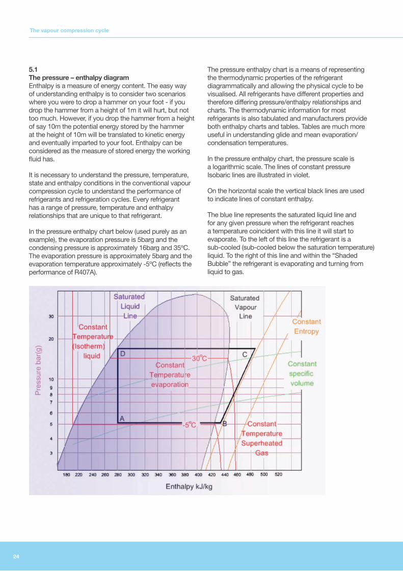
5.1 The pressure – enthalpy diagram Enthalpy is a measure of energy content. The easy way of understanding enthalpy is to consider two scenarios where you were to drop a hammer on your foot - if you drop the hammer from a height of 1m it will hurt, but not too much. However, if you drop the hammer from a height of say 10m the potential energy stored by the hammer at the height of 10m will be translated to kinetic energy and eventually imparted to your foot. Enthalpy can be considered as the measure of stored energy the working fluid has.
It is necessary to understand the pressure, temperature, state and enthalpy conditions in the conventional vapour compression cycle to understand the performance of refrigerants and refrigeration cycles. Every refrigerant has a range of pressure, temperature and enthalpy relationships that are unique to that refrigerant.
In the pressure enthalpy chart below (used purely as an example), the evaporation pressure is 5barg and the condensing pressure is approximately 16barg and 35ºC. The evaporation pressure is approximately 5barg and the evaporation temperature approximately -5ºC (reflects the performance of R407A).
The pressure enthalpy chart is a means of representing the thermodynamic properties of the refrigerant diagrammatically and allowing the physical cycle to be visualised. All refrigerants have different properties and therefore differing pressure/enthalpy relationships and charts. The thermodynamic information for most refrigerants is also tabulated and manufacturers provide both enthalpy charts and tables. Tables are much more useful in understanding glide and mean evaporation/condensation temperatures.
In the pressure enthalpy chart, the pressure scale is a logarithmic scale. The lines of constant pressure Isobaric lines are illustrated in violet.
On the horizontal scale the vertical black lines are used to indicate lines of constant enthalpy.
The blue line represents the saturated liquid line and for any given pressure when the refrigerant reaches a temperature coincident with this line it will start to evaporate. To the left of this line the refrigerant is a sub-cooled (sub-cooled below the saturation temperature) liquid. To the right of this line and within the “Shaded Bubble” the refrigerant is evaporating and turning from liquid to gas.
The vapour compression cycle

25
The black bubble line represents the saturated vapour line. All of the refrigerant has evaporated and is a gas. To the right of this line the refrigerant remains a gas and heating at constant pressure results in additional sensible heat and increased temperature and the gas is super-heated above the saturation temperature.
The vertical red lines (Isothermal lines) in the sub-cooled liquid region represent lines of constant temperature. The material is a liquid and does not expand thus the temperature remains ostensibly constant when the pressure reduces. During evaporation the temperature does not rise (special consideration must be given to refrigerants with high glide) and the process of evaporation takes place at constant temperature – the temperature is represented by the horizontal red lines (Isothermal lines).
In the superheated region the temperature lines are again illustrated in red and it can be seen that continuing to heat the refrigerant would result in superheating.
A sample line of constant entropy is illustrated in orange and on the same chart lines of constant specific volume m3/kg are drawn in green (again a couple of sample lines to allow clarity).
With a pressure enthalpy chart, the complete cycle and operating conditions of even the most complex refrigeration cycle can be readily understood.
5.2 The vapour compression cycle The vapour compression cycle is now examined and the opportunities for best practice and energy efficiency addressed appropriately.
5.2.1 Simple cycle After evaporation, the refrigerant gas is superheated slightly (this can be seen in the sketch opposite because point B lies in the superheated gas region to the right of the saturated vapour line). The superheating ensures that all refrigerant has been converted from liquid to gas and that liquid cannot be drawn into the compressor. If liquid is ingested the compressor will be damaged because the liquid is (to all intents and purposes) incompressible.
The compressor compresses the gas to the design discharge pressure (point C on the chart opposite). The temperature, pressure and the enthalpy have been increased because the compressor has done work on the refrigerant. This increase in enthalpy is termed the heat of compression.
The refrigerant is discharged from the compressor at the condensing pressure but the process of compression dictates that the gas will have gained considerable temperature and the gas will be discharged from the compressor at a temperature well above the condensing temperature. The discharge is superheated, for the gas temperature is far above the saturation temperature at the condensing pressure.
The refrigerant flows from the compressor in the hot gas line to the condenser and is cooled en-route. Cooling to the condensing temperature at the condensing pressure can be achieved by free cooling, a dedicated cooling stage, heat recovery or in a combined action within a cooler designed to de-superheat and condense. In large process installations, the superheat is recovered with a heat exchanger to provide cold store frost protection or water heating.
On larger installations de-superheating offers the opportunity for heat recovery and energy saving.
The refrigerant is then condensed in the condenser. To provide continuous refrigeration the condensing rate must match the evaporation rate. The condenser must reject heat at the same rate heat is absorbed from the system being cooled – otherwise you will run out of refrigerant. The condensing temperature may vary depending on the temperature of the surrounding cooling medium e.g. air or water.
The condensing pressure is the saturation pressure at the condensing temperature. If the condenser operation has to be conducted at a higher temperature because ambient temperature conditions are higher, then the condensing pressure will increase. The commensurate discharge temperature and the work conducted by the compressor will increase accordingly.
The liquefied refrigerant is returned from the Condenser to the control (throttle or expansion valve) via the liquid line.
As liquid refrigerant is evaporated, the latent heat of evaporation is added from the surroundings being cooled. The latent heat of evaporation at any given evaporation pressure is the difference between the saturated liquid enthalpy and the saturated vapour enthalpy. As refrigerant is returned through the throttle valve at the condensing pressure - the pressure is reduced to the evaporation pressure. Some of the higher energy refrigerant flashes leaving a colder (latent heat removed by flashing) liquid refrigerant to be evaporated. Therefore for every kg of charge circulated only a fraction of this is returned to the evaporator as a liquid to be evaporated and provides cooling by evaporation.

26
If the refrigerant is cooled below the condensing temperature it is sub-cooled. Sub-cooling can be achieved by allowing heat loss from the liquid line or from the refrigerant receiver. The receiver is simply a buffer of refrigerant to accommodate variations in system demand and allow the other system components to catch up with changes in demand. The refrigerant will cool to near ambient conditions before entry to the expansion valve (control or throttle). The pressure however will remain the same as the condensing pressure. The refrigerant will remain liquid if the system pressure is not dropped below the saturation pressure for the sub-cooled temperature.
The system pressure differential (that is the pressure difference between the high pressure condensing side and the lower pressure evaporation) is maintained by a control valve (expansion or throttle valve). The high pressure (and preferably sub-cooled liquid) is passed through the control valve and the pressure is reduced to the evaporation pressure. The evaporation pressure is considerably lower than the condensing pressure and the relatively high temperature refrigerant (albeit sub-cooled) cannot remain a liquid at the lowered pressure. The refrigerant has to be cooled to the saturation temperature at the evaporation pressure and that is achieved adiabatically (without exchange of heat to the surrounds) as a proportion of the refrigerant flashes and absorbs the latent heat of evaporation at the lowered pressure.
So as the liquid passes through the control valve the pressure is reduced, a proportion of the liquid evaporates (flashes to vapour) and the mix is cooled. In this simple cycle, the flash vapour is drawn round the system but provides no real useful cooling (gas to gas heat transfer rates are very small compared with gas to liquid heat transfer rates) and consequently for every unit mass refrigerant circulated only a proportion is liquid and vapourises in the evaporator providing useful refrigeration effect.
Because the cooling of the refrigerant on expansion is achieved adiabatically, the net enthalpy of the mixture (flash vapour and cooled refrigerant) remains constant and that expansion process is illustrated in the chart opposite by the Line D to A where the enthalpy is considered constant.
The refrigeration effect then can be determined by the enthalpy leaving the evaporator (this point can be considered as nominally coincident with the enthalpy at the saturated vapour line for the evaporation pressure, or a little to the left of point B in the chart opposite). Point B is the suction point and here some superheat has been gained.
5.2.2 Simple saturated cycle To consider the theoretical case it might be assumed that the refrigerant leaves the evaporator as saturated vapour (on the saturated vapour line with no superheating) and is immediately compressed to the condensing pressure and that the liquid leaves the condenser at the condensing temperature (with no sub-cooling) and that the compression is isentropic. That process is illustrated on the chart opposite where there is no superheating.
In the simple cycle the refrigeration effect is simply the enthalpy at point B – the enthalpy at point A. The enthalpy at point A is the same as that for the saturated condensing condition point D - therefore the refrigeration effect is hB -hD (approximately 426kJ/kg – 281kJ/kg) or 145kJ/kg.
Because the work done in the compressor is considered to be isentropic (the compression follows an orange line of constant entropy) the work done by the compressor is the heat of compression or hC - hB (approximately 473kJ/kg – 426kJ/kg) or 47kJ/kg. So the compressor work done per kg of refrigerant circulated is 47kJ/kg.
The total heat rejected by the condenser (which in this case includes the superheat from compression) is hC -hD (approximately 473kJ/kg – 281kJ/kg) or 192kJ/kg.
The latent heat rejected by the condenser is hC’ - hD (approximately 447kJ/kg – 281kJ/kg) or 166kJ/kg and accordingly the superheat hC - hC’ = 26 kJ/kg.
The vapour compression cycle

27
5.2.3 Coefficient of performance The theoretical coefficient of performance or COP refrigeration effect to power expended can be determined as 145kJ/kg/ 47 kJ/kg or in this case 3.08.
5.2.4 The impact of suction temperature on efficiency If the same refrigerant were used but the evaporation temperature is dropped then there is detrimental effect on cycle performance.
The refrigeration effect is simply the enthalpy at point B’ – the enthalpy at point A’. The enthalpy at point A’ is the same as that for the saturated condensing condition point D - therefore the refrigeration effect is hB’ - hA’ (approximately 420kJ/kg – 281kJ/kg) or 139kJ/kg.
The work done by the compressor is the heat of compression or hC’ - hB’ (approximately 482kJ/kg – 420kJ/kg) or 62kJ/kg. So the compressor work done per kg of refrigerant circulated is 62kJ/kg.
The theoretical coefficient of performance or COP refrigeration effect to power expended can be determined as 139kJ/kg/ 62 kJ/kg or in this case reduces to 2.24.
5.3 The impact of condensing temperature on efficiency
If the same refrigerant were to be used but the condensing temperature is elevated then there is a detrimental effect on the cycle performance. The refrigeration effect is reduced and compressor power is increased.
The refrigeration effect is simply the enthalpy at point B – the enthalpy at point A’. The enthalpy at point A’ is the same as that for the saturated condensing condition point D’ - therefore the refrigeration effect is hB - hA’ (approximately 425kJ/kg – 290kJ/kg) or 135kJ/kg.
The work done by the compressor is the heat of compression or hC’ - hB (approximately 482kJ/kg – 425kJ/kg) or 57kJ/kg. So the compressor work done per kg of refrigerant circulated is 57kJ/kg.
The theoretical coefficient of performance or COP refrigeration effect to power expended can be determined as 135kJ/kg/ 57 kJ/kg or in this case reduces to 2.36.
5.3.1 Summary of the basic cycle Raising condensing pressure reduces the useful refrigeration effect because more low pressure liquid mass is for flash cooling the total circulated refrigerant mass. The compressor power is also increased. The combined effect is to have a marked effect on the COP and the kW power consumed per kW of refrigeration provided.
Lowering the evaporation pressure has a similar, if not larger detrimental effect. Analysis of the simple saturated cycle explains why it is important to keep the condensing temperature as low as possible and keep the evaporation temperature has high as possible.

28
5.4 Practical cycle operation In practice, refrigeration cycles are far more complex and numerous different and relatively complex solutions are possible. Again here this guide will concentrate on the key issues and effects.
5.4.1 Suction superheating without useful cooling The refrigerant may well leave the evaporator as a saturated vapour, but it is usually necessary to ensure a small amount of superheat and elevated temperature to ensure no liquid enters the compressor.
The impact of suction superheat can be seen above. The refrigeration effect stays the same because in most cases the superheating occurs outside the evaporator as the suction line is heated by ambient condition. Superheating that takes place outside the evaporator and provides no useful refrigeration effect is termed un-useful super heat.
The sensible heating of the post evaporator refrigerant has several detrimental effects. The cycle points are displaced requiring more compressor power for the same refrigeration effect. The COP is therefore reduced. The specific volume of the superheated gas is much larger (lower density and the compressor cannot shift the same mass with each piston stroke or screw revolution) and the condenser must reject a larger quantity of sensible heat before condensation can begin. The physical capacity is reduced and a larger compressor is required.
Some un-useful superheat will normally be prevalent. As the evaporation temperature is reduced, the impact of un-useful superheat will have an increasing impact on capacity and COP. Heat gains to the suction line are evidenced by frosted pipelines, valves and or water formation on the suction lines. Insulating the suction lines
properly from evaporators and particularly in plant rooms to prevent un-useful superheat is therefore an essential requirement.
The degree of performance loss and loss of refrigeration effect may be calculated from tables or by inspection of the relevant refrigerant chart and the measurement of the cycle temperatures, and the suction temperature at the compressors and by making a comparison with the design specification. Loss of capacity means that the compressors will work much harder and longer for the same effect so the undesirable net effect is increased electricity consumption.
5.4.2 Suction superheating with useful cooling Where the superheat provides useful evaporator cooling, then in some cases (depending on the refrigerant) the total refrigeration effect expressed as a ratio of compression heat increases (greater COP). Despite the additional power and the loss of capacity the cycle efficiency is actually improved beyond that of the simple saturated cycle. In some cases superheating is required to ensure the refrigerant is all evaporated and dried before entry to the compressor.
Therefore useful superheat can improve system efficiency. However, because gas/gas transfer rates are much smaller than gas liquid transfer rates, superheating in the evaporator (providing useful cooling) would normally require much larger evaporators and improved heat transfer arrangements with associated penalty – therefore as a rule useful superheating should also be kept to a minimum.
Some superheating will be necessary to operate the Thermal Expansion Valve (TXV) or to give a reference condition for electronic expansion valve (EEV).
5.4.3 Sub-cooling the liquid after the condenser
The vapour compression cycle

29
Sub-cooling refers to the cooling of condensed refrigerant below the condensing temperature. Sub-cooling can be achieved with ambient cooling over time, with an oversized air cooled condenser or additional water cooling. The condensing temperature is generally set to allow rapid heat transfer from the condenser to the ambient surround and that dictates there is a temperature differential between the condenser and the cooling air temperature (or water temperature in the case of a water cooled system). At condensation the refrigerant will be at a temperature above the ambient conditions. However if the refrigerant is transferred to a reservoir or to a sub- cooler, ambient or active cooling may be further employed to drop the temperature of the refrigerant closer to that of the ambient condition.
The refrigeration effect is increased from hB - hA to hB - hA’ and the compressor power input remains unchanged. That improves the COP and because the refrigeration effect per unit mass of circulated refrigerant is increased, the compressor capacity can be reduced. The net effect is a reduction in electrical power consumption.
5.4.4 Using cold superheated gas to provide sub-cooling The benefits conferred by subcooling can be realised by exchanging the heat with the suction gas after the evaporator. Despite the fact that un-useful heating is not desirable, the practical operation of a refrigeration cycle will dictate that some heating is inevitable, not least transfer from the hot compressor - if that can be controlled superheating can be used to effect sub-cooling rather than simply uncontrolled superheating then this method of economising can be advantageous (fully explained in due course).
5.5 Multistage cycles The largest power consuming component in any vapour compression cycle is the compressor. The condenser and evaporator fans are generally very much smaller and consume significantly less power. The energy consumption is directly proportional to the lift (as illustrated) or what is termed the compression ratio. When the pressure ratio is higher, the compressors (all types) suffer additional losses. In the screw compressor the maintenance of pressure differential must be maintained between the ends of the rotors and the internal face of the casing. At higher pressure ratios and particularly low loads the leakage across the rotor increases and efficiency reduces (although liquid refrigerant injection as opposed to oil injection can be used for sealing). The piston compressor can usually never eject all air from the cylinder and any remaining on the down stroke expands again restricting inward flow from the suction side. The performance of some refrigerants is not ideal and
operation over a very large pressure differential will have a relatively low isentropic efficiency with high discharge temperatures. Consequently a large lift is to be avoided for the reasons given in this guidance.
For most smaller scale operations, even those with evaporation temperatures of up to -30ºC a single lift is common – for the capital cost of multistage compression weighs too heavily against installation. However, for large or very cold blast freezing and cold storage solutions/applications, typically larger Ammonia plant, two stage compression is necessary and desirable from an energy efficiency perspective.
Two stage compression is much more efficient than single stage compression. In the screw compressor the leakage is significantly reduced at all speeds because the individual compressor ratios are smaller. The final discharge temperature can be kept low with intercooling between the low pressure compressor (LP) and the high pressure compressor (HP). A small amount of liquid refrigerant is injected from the receiver into the outlet line of the LP compressor. The liquid refrigerant evaporates and thus cools the intake gas for the HP compressor.
As suction temperatures drop (refer to 5.2.4) efficiency will also reduce (because the lift is increased) and disproportionately so because of the volumetric efficiency and leakage limitations of compressors. For low temperature applications two stage compression must be considered and the operational cost benefit evaluated.
5.6 Pumped versus DX The term DX is used to describe a solution where refrigerant is vaporised in the evaporators and pumped refers to a system where vaporisation as refrigerant flashing takes place within a purpose designed flash vessel (surge drum) and cooled refrigerant is returned to that vessel. Cold refrigerant is pumped from the vessel to fan convected coolers in the cold storage area or to a glycol heat exchanger and thereafter glycol is circulated to the coolers.
5.7 Economisers The amount of energy depends on the quantity of refrigerant circulated and the compression ratio. After de-superheating and condensing the liquid refrigerant may be slightly sub-cooled (refer to 5.4) by heat transfer from the warm refrigerant to ambient surrounds. Here any sub-cooling is advantageous for it provides colder liquid at the condensing pressure. Less flash cooling work is required through the TXV (refer to section 8 for a detailed explanation).

30
The economiser works by taking a small amount of liquid (just sub-cooled) and flashing this at an intermediate suction pressure. As the flash vapour is expanded to the intermediate suction pressure the cold gas is used to sub-cool the remainder of the refrigerant flow from receiver to main evaporator. The additional work done recompressing the flash vapour is readily offset by the sub-cooling and additional refrigeration effect obtained (refer to the preceding sections on sub-cooling).
There are numerous variants of this arrangement (too many to discuss here) but it is sufficient to know the concept of economiser in the context of the cycle. This is best illustrated in the diagram below.
The vapour compression cycle

31
6.1 Compressor types . . . . . . . . . . . . . . . . . . . . . . . . . . . . . . . . . . . . . . . . . . . . . . . . . . . . . . 32
6.1.1 Piston compressors . . . . . . . . . . . . . . . . . . . . . . . . . . . . . . . . . . . . . . . . . . . . . . . . 32
6.1.2 Screw compressors . . . . . . . . . . . . . . . . . . . . . . . . . . . . . . . . . . . . . . . . . . . . . . . . 33
6.1.3 Scroll compressors . . . . . . . . . . . . . . . . . . . . . . . . . . . . . . . . . . . . . . . . . . . . . . . . 33
6.2 Application guidance . . . . . . . . . . . . . . . . . . . . . . . . . . . . . . . . . . . . . . . . . . . . . . . . . . . . 33
6 Compressors and capacity control

32
Compressors and capacity control
6.1 Compressor types There are three main types of compressor
• Piston compressors
• Screw compressors
• Scroll compressors
These are all positive displacement compressors and they are all capable of being driven with variable speed drives, although other methods of capacity control are sometimes preferable. These are not dynamic compressors and the power consumption does not reduce as a cube function with motor speed and generally the efficiency of compression reduces with operating speed.
In some very large applications, the use of a centrifugal compressor might be employed. This is a dynamic compressor but these operate with a limited pressure differential and thus the opportunity for inverted drive is limited to large scale applications.
There are other types of compressor but the use is limited and this guide addresses the common types listed above. These compressors have different characteristics and the use depends on the application, temperature, load profile and refrigerant.
6.1.1 Piston compressors The piston compressor remains the most common type of compressor in service. Piston compressors are positive displacement meaning that a quantity of gaseous refrigerant is trapped and displaced. Most compressors are single acting (compress only in one stroke direction) and may incorporate one or more pistons arranged in V-bank. The compressor is similar to a car engine in that as the piston descends an inlet valve opens drawing in gas from the suction line, the piston reaches the bottom of the stroke and the inlet valve is closed, the piston then proceeds up the cylinder reducing the volume in the cylinder and compressing the gas at or near the top of the stroke depending on valve arrangements and settings, the exhaust valve opens discharging the compressed refrigerant to the discharge line.
Reciprocating compressors have been around for a long time and that means cost efficient production has been evolved and reciprocating options can offer lower cost.
Hermetic/ compressor
Motor and compressor together in hermetically sealed container
Generally fully hermetic types used for small scale domestic applications. Typically on/off capacity control
Semi hermetic Semi hermetic can be accessed for maintenance
Medium commercial (Field Serviceable)
Open drive Motor separate and drives via input shaft. Motor component interchangeable
Generally>10kW, Capacity control arranged by various methods including typically cylinder off loading and/or variable speed drive.
For small domestic and medium sized compressors operation is controlled by the suction pressure. The use of mechanical differential switches is prevalent.
The refrigerant flow rate varies depending on the system demand and the operating performance of the TXV (or EXV) and unless the capacity of the compressor is altered the pressure of the suction side will continue to drop as the compressor scavenges the suction line. The system load may vary from zero to max design load. The compressor therefore must have some form of capacity control. In the case of the reciprocating compressor that might be a restriction to the compressor inlet (Inlet throttling) or a restriction to the compressor out let, or discharge gas may be recirculated to the inlet or the compressor may be turned off and on or the compressor may unload cylinders.
The operation of a piston compressor is a variable volume ratio operation. That is to say the piston stroke to discharge valve opening point will vary depending on the condensing pressure and valve settings.
If the screw compressor is designed as fixed volume ratio, the discharge pressure is typically matched to the anticipated condensing condition. When the condenser has improved cooling or the chiller demand is low the fixed ratio screw compressor typically cannot compensate or take advantage of reductions in condensing pressure afforded by lower ambient temperature conditions.
Typically the performance of reciprocating chillers is 10-15% better than screw compressors.

33
The performance of screw chillers “operating off design” is significantly worse than a reciprocating compressor. If the ambient temperature drops, and the screw discharge is retained at the design discharge pressure (this is regardless of VSD - the machine is positive displacement) the machine cannot take advantage of a potentially reduced discharge pressure and associated power reduction (the COP does not improve).
The same is also true for higher than design condensing conditions for initially the fixed ratio screw will attempt to discharge at the design pressure, resulting (if the condenser pressure is higher) in initial back flow. Eventually a balance will be achieved but the fluctuation in discharge pressure is thermodynamically inefficient and the efficiency of the screw compressor drops of at condenser pressures above design.
6.1.2 Screw compressors
The screw compressor is also a positive displacement machine. Air is drawn in through an intake port and trapped between lobes of two intermeshing screw rotors. The intermeshed volume decreases along the rotor length and the air is progressively compressed until discharge. The rotor length is fixed and thus the compression ratio (Volume Ratio) essentially fixed, regardless of speed. The variation of speed does not change the volume ratio.
To effect capacity control (variable volume ratio) and overcome some of the issues discussed in 6.1.1 manufacturers have adopted the use of sliding intake and discharge ports to move these points on the screw length. The discharge pressure may be varied allowing superior operational flexibility.
The use of variable speed capacity control affords a good proportional reduction in power consumption to a point. However, at high percentage turndowns the leakage of compressed refrigerant around the rotors, inverter losses
and reduced motor efficiency provide for increasingly poor part load performance and VSD screw compressors will not operate efficiently at high turn down ratios.
6.1.3 Scroll compressors Scroll compressors are also positive displacement compressors (routinely found in domestic refrigeration and heat pumps). The design incorporates a fixed scroll and an orbiting scroll. The scrolls are intermeshed and sealed between plates. The refrigerant entrained at the periphery of the scroll is progressively squeezed to the centre of the scroll (the concept is similar to that of the screw compressor). The scroll compressor is also a fixed volume ratio compressor and therefore works most efficiently when the system pressure differential is the same as the compressor differential for the reasons given in 6.1.1. Over or under charging the system will reduce efficiency.
The scroll type compressor will produce performance similar if not better than a reciprocating compressor when under normal operating conditions. Capacity modulation in the small scroll compressor (<4kW) is usually effected by opening a bypass port which allows some bleed around the compressor. At larger sizes combinations of bypass and VSD may be used to provide capacity control.
At small scale (and where the condensing pressure is such that the scroll is operated at the design point) there is little to choose between scroll and reciprocating compressors in terms of performance.
The scroll compressor would be substantially cheaper to purchase than a reciprocating type, and generally require less maintenance.
6.2 Application guidance

34
7.1 Part Loads . . . . . . . . . . . . . . . . . . . . . . . . . . . . . . . . . . . . . . . . . . . . . . . . . . . . . . . . . . . . 35
7.2 Performance summary . . . . . . . . . . . . . . . . . . . . . . . . . . . . . . . . . . . . . . . . . . . . . . . . . . . 35
7.3 Compressor selection . . . . . . . . . . . . . . . . . . . . . . . . . . . . . . . . . . . . . . . . . . . . . . . . . . . 35
7.4 Summary key issues . . . . . . . . . . . . . . . . . . . . . . . . . . . . . . . . . . . . . . . . . . . . . . . . . . . . 36
7 Load Matching

35
Using the correct tools for the job is always important and the adage “using a sledge hammer to crack a nut” is relevant. The refrigeration system must incorporate sufficient flexibility to meet the varying demands placed on the system. Assessing and understanding the load profile (refer to section 11) is most important. Unfortunately, system design must be for the worst case scenario e.g. the hottest weather or the largest initial cooling load and in practice these conditions often only exist for a small percentage of the overall operating time.
7.1 Part Loads When a compressor is operated at part load, the efficiency can reduce markedly (refer to section 6 of this guide). The efficiency reduction varies with compressor type and the design of any capacity control. Unloading cylinders in the reciprocating compressor is a moderately efficient way of reducing capacity however the drag and rotational mass and friction losses still remain. The power reduction is broadly linear.
Reciprocating compressors can be equipped with a VSD for capacity control. The capacity reduction directly proportional to speed. Energy consumption reduces almost proportionally but there is still a drag and motor losses factor. It is unusual to find a VSD equipped reciprocating compressor because cylinder unloading effectively offers exceptional partload efficiency.
Although the screw compressor may be varied almost infinitely the potential for air short circuiting at lower speeds means that the power reduction is not linear and efficiency reduces at lower speeds. Larger screw compressors may very likely be retrofitted with VSD and offer some considerable saving, e.g. 20%, over slide valve arrangement for capacity control (which effectively just shortens the enclosed flute volume and the compression path). The VSD could be used in conjunction with slide valve but the minimum speed restrictions of the machine would have to be observed.
Scroll compressors are fixed compression ratio machines but even the scroll compressor can be driven by VSD offering a means of efficiently reducing capacity (albeit to the same discharge pressure).
7.2 Performance summary In summary the lower cost of reciprocating compressors at and below 30kW (40-60% less) make these the compressor of choice for small application. Unless these were designed and installed with a variable speed drive, it is unlikely they can be retrofitted with a VSD because oil pressure and cooling will not be maintained at reduced speed. Offloading is likely to be the capacity solution.
At small scale, screw compressors are less often used but can be deployed with VSD. The performance over the entire operational range should be checked because air short circuit at very high turndowns will not be efficient (the specific power consumption will increase markedly with or without VSD). At larger scale screw compressors will offer similar specific power consumptions to reciprocating compressors (particularly with the use of intermediate port and flash gas compression) and the capital cost is comparable or lower. Operating large screw compressors at low loads is not an economic option. The stipulated turndown is not the issue – the specific power consumption at turndown is the important factor. It is not efficient to operate screw compressors at low turndowns even with VSD.
7.3 Compressor selection In selecting the size and number of compressors to meet the load it is important (if the plant is to operate efficiently) to understand these compressor limitations and to match the number and the size of the compressors to the load. If the design load (which will likely assume full product loading on the hottest day of the year) greatly exceeds the typical operational load and, for example, it would be inefficient to have a large screw compressor operating at 25% load (any type) under the normal operational circumstance. For that reason multiples of compressors are better suited for meeting loads with large changes. The combination of multiple compressors and multiple cylinder offloading offers an almost linear turndown over a large range. However it is possible (when specifically designed) to incorporate variable speed drive for some reciprocating designs, offering even finer control.
The important factor in design is to ensure that small part load conditions are met with lowest (or optimised) specific energy consumption (kW/per kWh refrigeration effect) and that will generally require that small part load conditions are met with multiples of small compressors rather than large compressors using VSD or off loading or both.
The concept of running one machine at high capacity and one as top up is broadly correct – however, the very specific characteristics of screws and reciprocating compressors (and this will be specific to machine type) mean that some care has to be taken in designing to achieve lowest overall specific power consumption.
Where multiple reciprocating compressors are used and where it is possible to balance the load across two compressors at fairly high percentage output – this will potentially provide a better overall specific power consumption than running one flat out and the other under loaded. This is simply because reciprocating compressors offer an improved efficiency at slightly less than full load.
Load Matching
36
Load Matching
Where multiple screws are used (and bearing in mind that the screw performance will deteriorate at low load and is best at full load) then part load conditions are best met by running one screw flat out and the other as top up until the load can be met using both machines at sufficiently elevated operating points (at a higher % full load).
7.4 Summary key issues In general:
• Multiples of smaller machines will be better to meet variable loads.
• Turning big machines down with a VSD is false economy.
• VSD help reduce power consumption but compressor size matters.
• The concept of running one machine at high capacity and one as top up is broadly correct. However because reciprocating compressors perform best at just under 100% capacity and because screw compressors performance drops of dramatically at lower (less than 35%) capacity, a careful balance of compressor multiples has to be used to get the best efficiency.
37
8.1 Thermal Expansion Valves (TXV) or (TEV) . . . . . . . . . . . . . . . . . . . . . . . . . . . . . . . . . . . . 38
8.2 Electronic Expansion Valves . . . . . . . . . . . . . . . . . . . . . . . . . . . . . . . . . . . . . . . . . . . . . . 39
8.3 Reducing condenser pressure . . . . . . . . . . . . . . . . . . . . . . . . . . . . . . . . . . . . . . . . . . . . . 39
8.4 Ambient condensing conditions Northern Ireland . . . . . . . . . . . . . . . . . . . . . . . . . . . . . . 39
8.5 Floating Head control . . . . . . . . . . . . . . . . . . . . . . . . . . . . . . . . . . . . . . . . . . . . . . . . . . . . 40
8.6 Cautionary Issues. . . . . . . . . . . . . . . . . . . . . . . . . . . . . . . . . . . . . . . . . . . . . . . . . . . . . . . 40
8.7 Evaporator Sizing . . . . . . . . . . . . . . . . . . . . . . . . . . . . . . . . . . . . . . . . . . . . . . . . . . . . . . . 40
8.8 Liquid Pressure Amplification . . . . . . . . . . . . . . . . . . . . . . . . . . . . . . . . . . . . . . . . . . . . . 41
8 Expansion valves and Head pressure control

38
Expansion valves and Head pressure control
The refrigerant condensed in the condenser and subsequently stored in the refrigerant receiver may be usefully sub-cooled here (refer to 5.4.3 of this guide). The refrigerant is stored at (or close to) the condensing pressure and the liquid refrigerant must be passed through the expansion valve to effect cooling and pressure reduction.
The operation of the expansion valve differs from system to system and it is necessary to understand the basic operation to understand why ill-conceived energy efficiency measures may adversely affect the operation of your plant.
8.1 Thermal Expansion Valves (TXV) or (TEV) The most common valve type is a thermo mechanical device referred to as a thermal expansion valve. The thermal expansion valve (TXV) is a device designed to meter refrigerant and afford a regulated flow of refrigerant from the receiver through to the evaporation system. The TXV does not provide capacity control or head pressure control. However some devices rely on a differential head (pressure difference between high pressure and low pressure) to operate accurately without hunting or surging.
The TXV may be considered as a servo assisted throttle valve. The servo assistance is provided by a diaphragm. The thermo-mechanical expansion valve relies on a remote measurement of the refrigerant temperature as it leaves the evaporator. The temperature of the suction line after the evaporator is measured by a temperature bulb and refrigerant filled capillary. When the temperature rises (and a prerequisite superheat is measured), the refrigerant in the capillary expands and pushes on one side of the diaphragm opening the TXV and allowing more refrigerant flow. The balancing pressure on the diaphragm is provided by the evaporator pressure and a preset spring assistance (superheat spring). The combination of relatively low evaporator pressure and spring assistance will, when the post evaporator temperature is low, cause the valve to close and maintain a specified degree of post evaporator superheat (thus preventing the suction of liquid to the compressor).
Changes in load cause the TXV pin to move. Increasing the superheat will cause the TXV to open and decreasing the superheat will cause the TXV to close.
Because a small amount of superheat is absolutely necessary to prevent liquid flow from the evaporator into the suction line the spring pressure (superheat spring) will be preset to afford a static superheat – the full design flow capacity will not be achieved until a further margin of
superheat is achieved. In other words the valve flow is managed by a variation in superheat measured at the evaporator outlet. To achieve full flow there has to be a larger superheat. Superheating reduces the COP and system performance. A minimum superheat will be required to stop the TXV hunting (cycling open and closed).
If the valve is not adjustable it must be selected for the refrigerant, system load and very careful refrigeration design to ensure that the compressor capacity at all evaporator loads is adequate. A small degree of superheat ensures that all liquid is evaporated.
If the TXV is adjustable then the setting of excessive superheat will result in underperformance of the evaporator - because the liquid refrigerant is all evaporated too early and there is insufficient metered flow to meet the evaporator demand. That reduces the evaporator capacity (because gas/gas heat transfer rates are lower than gas/liquid transfer rates).
The evaporator pressure and the superheat spring balance the temperature sensed bulb pressure to control the flow of refrigerant.
In some cases if the system has a very large pressure drop within the evaporator, the superheat temperature will be insufficient to open the valve and because the flow is fully evaporated the heat transfer compounds the difficulty in achieving the required superheat to open the valve. Since the pressure drop through the evaporator will increase with load the compounded effect will be manifested when the required TXV flow is highest. The system will reach a self-regulated maximum flow. Some TXV may be equipped with an external pressure equalising line which will allow the redress of this pressure deficiency. The post-evaporator pressure (as opposed to the pre-evaporator pressure) is sensed on the closure side of the diaphragm.
It is perhaps evident that TXV operation is a balancing act and the valve must be designed to operate with the refrigerant, and the design pressure differential across the TXV (Typically 5+bar(g). The thermostatic expansion valve is a precision component that works well in the correct design context.
Where TXV do not work well is when ill-considered adjustments to condensing pressure are made to improve efficiency – (head pressure control). If the pressure on the HP side is reduced to low, the liquid will flash on the condenser side starving flow of liquid. The loss of differential pressure will also affect the balancing.

39
8.2 Electronic Expansion Valves The minimum head differentials and minimum superheats required for the correct operation of the TXV provide some limitation to the condensing temperature and result in the potential elevation of suction and discharge temperature, both having a detrimental effect on cycle efficiency. Correctly set up and sized, refined control of the refrigerant flow to the evaporator is possible. However the Electronic expansion valve offers a more refined approach to the control of flow without the need for the same across valve, pressure differential.
The electronic expansion valve (EXV or EEV) is a stepper motor controlled precision valve capable of very accurate positioning. The pressure and the superheat temperature after the evaporator are measured with precision measurement probes and the condition and these measurements are supplied to an electronic controller (superheat controller), a stepper motor driver, or PLC which derives a real time position signal for the EXV. The response of the EXV to evaporation conditions is instantaneous and accurate - moreover the change of conditions at the evaporator may be sensed and the stepper motor response managed with a PID algorithm to manage the EXV flow and evaporator recovery to change in demand conditions.
In the conventional refrigeration system the suction superheat is controlled so as to afford the TXV safe operational margin. This raises the discharge temperature for any given condensing pressure and requires a bigger condenser (potentially with superheat recovery). The net effect has a detrimental effect on the COP. Similarly, the lagging reactive control offered by the TXV can lead to some inaccuracy in metering and the over and undersupply of refrigerant. Generally the TXV must be operated with “larger control margins” leading to additional inefficiency. The EXV offers much more precise control and with that precise control comes an energy saving benefit.
Because the EXV does not require the same extent of differential pressure for accurate governance of the expansion, it is often possible to reduce the condensing pressure (head pressure) and reducing the condensing pressure together with a smaller superheat margin (refer to sections 5.4.2 and 5.4.3 of this guidance) affords a dramatic improvement in COP (the ratio of refrigeration effect to compressor power).
The benefits of improved control will be manifest at all refrigeration temperatures. However, the maximum control improvements will generally be realised for plant working at medium temperature, whereas head pressure control
will have benefit across a wide range of operating temperatures, refrigerants and larger commercial refrigeration plant.
8.3 Reducing condenser pressure Many, if not most, mechanical and electronic control systems will cycle condenser fans off and on in order to maintain a fixed condensing pressure to take advantage of lower ambient conditions. That fixed condensing pressure is often selected by the manufacturer’s tables to cater for every seasonal eventuality that will be encountered by the condenser whilst still achieving full design refrigeration effect. Worse still, the packaged system design may have been selected for the regional sales area – so if you buy a system from a Southern European supplier who has no experience of Belfast in winter, it may well be designed for a differing regional climate. There will likely be opportunities to reduce condensing pressure.
It should be noted that operation with an excessively low condensing pressure (and conventional TXV) evaporator pressure may also drop to an unacceptable level with the potential for compressor damage. In some circumstances excessively low pressure must be corrected by restricting condenser airflow or refrigerant flow.
8.4 Ambient condensing conditions Northern Ireland The dry bulb conditions for Northern Ireland are illustrated below - the red line illustrates actual maximums achieved in 2012 - as a typical example.
An air cooler (refrigerant to air as opposed to refrigerant to water) will have to operate with a relatively high LMTD (because the heat transfer coefficients are poorer) and will operate with a 12-15ºC differential over the dry bulb temperature. Given that a dry air cooler may be designed to operate with 12-15ºC differential over the prevailing ambient dry bulb, then for the greater part of the year (>60%) a theoretical condensing temperature of 30ºC

40
(or in fact less) could theoretical be achieved whilst still maintaining a very large overall pressure differential. (Pressure differential across the expansion valve – both mechanical and electronic valves have minimum differentials).
To achieve that reduced condenser temperature, the area of the condenser must be increased significantly and cooling airflow maintained effectively. It is however best to have a large condensing area and lower fan power (or else the fan power will become excessive and reduce energy savings).
8.5 Floating Head control If the condensing pressure is allowed to float up and down with the prevailing ambient conditions to say a maximum ambient db of 35ºC in summer, then for most of the year the condensing pressure/temperature can be dropped much lower. The specific purpose of floating head control is to make best use of colder ambient conditions to reduce the compressor lift (the lift in pressure that the compressor must achieve) and thus improve cycle efficiency as a very rough approximation the compressor power will be reduced by 3% per degree of temperature lift from suction to discharge temperature.
Floating head control is widely adopted now – by all major manufacturers and their systems are capable of floating head operation, typically based on a fixed temperature difference between condenser and ambient condition. To derive best benefit from that arrangement the condenser fan power has to be minimised using variable speed drive driven fans.
• Any new procurement should be equipped with full floating head control
• The system should have the condensers sized and controlled to allow the condensing temperature to drift up and down by ambient + suitable heat transfer differential to maximise energy saving
• Electronic expansion valves should be used to govern refrigerant flow
• Compressors should be driven by variable speed drive
The savings potential from floating head control, VSD fan control and VSD compressor control is entirely dependent on load factor, size of plant, evaporation temperature and a wide range of other factors, suffice to say that for commercial refrigeration systems (liquid or air cooled) the savings potential is significant and savings of 15-20% over a conventional arrangement might well be expected. In cases where the plant has long operational hours, the
additional capital which may be up to 50% more is readily offset by the operating cost reduction.
As a rule of thumb it is good practice to maintain pressure head on the expansion device by arranging for the receiver and expansion device to be physically much lower than the condenser. Reducing the compressor lift will reduce the amount of superheat available for underfloor heating or water heating and in retrofitting systems a substantial reduction in heat recovery may be expected.
8.6 Cautionary Issues Reducing the head pressure when practical is a good way of saving money. Adjustment may have other implications and require other system modifications. For example operating with very low superheat margins may require additional protection for the compressor by way of suction accumulation.
It is equally important to ensure that the compressor cannot pull excessive vacuum on start up where the differential pressure across the expansion valve is not sufficient to permit adequate refrigerant flow.
As condensing temperature drops, the evaporation temperature will also drop if the compressor capacity remains constant. It will be necessary to reconfigure controls to afford this.
In some cases the reduced temperature may prevent the use of Hot Gas Defrost and an alternate solution for defrost must be established.
These issues are beyond the knowledge of most energy consultants. Before converting system to EEV and floating head control – you must consult an experienced Contractor or liaise directly with the system manufacturer.
8.7 Evaporator Sizing The cooling capacity of an evaporator is directly proportional to the log mean temperature difference (LMTD) between the airflow through the coil, and the temperature of the refrigerant (ex of superheating). The rate of heat transfer is dictated by the overall heat transfer coefficient x the surface area x the temperature difference. A larger temperature difference allows a smaller evaporation area and the reverse is true. So if the evaporators are made as large as possible, the temperature difference required is reduced and the evaporation temperature can be brought closer to the desired air temperature. Raising the evaporation temperature by even a few degrees allows reduced
Expansion valves and Head pressure control

41
compressor work and reduced power consumption for the same refrigeration effect. Raising the evaporation pressure has much the same effect as reducing the head pressure, for it reduces the overall lift provided by the compressor. Refer to section 5.2.4.
8.8 Liquid Pressure Amplification The expansion valve requires some degree of pressure differential across the valve for correct function. Reducing head pressure (the pressure of the condenser) reduces that differential pressure (regardless of sub-cooling) and may very well affect the correct function of a thermostatic expansion valve. Moreover circulation of refrigerant depends to an extent on the pressure differential in the system.
Liquid pressure amplification LPA refers to the artificial application of pressure differential by pumping. As only a liquid refrigerant may be pumped this is applicable post condensation and may be used to retain a large pressure differential and refrigerant circulation in other wise low pressure (low condensing temperature) circumstances.
LPA may become necessary when reducing condensing pressure creates an unacceptably low pressure differential. LPA is a means of maintaining pressure differential around the refrigeration circuit but particularly across a thermal expansion valve. Electronic expansion valves may generally be operated with a lower differential but must be sized correctly.
In many cases the need for LPA can be avoided with good design. In some cases if significant reductions in condenser pressure are to be achieved it may be necessary in retrofitting to use LPA as a means of retaining TXV differential and total circulated volume. LPA should not be considered as a means of implementing floating head condenser control. (There are other factors, as discussed that must be considered). LPA will, in specific cases, be suited to larger refrigeration systems.

42
9 Optimising Defrost

43
When an evaporator is working below freezing (as many will be), the air flow through the evaporator will likely reduce below the dew point causing, initially, condensation and subsequently, freezing. This has the direct effect of reducing heat transfer into the evaporator and thus loss of evaporator and system efficiency. This is overcome by periodically stopping the flow of refrigerant and heating the evaporator to melt ice formation (collected in a drip tray and put to drain).
There are three principal methods of defrosting – electric defrost, hot gas defrost and off cycle defrost.
• Off cycle defrost is really only suitable for situations where the air temperature in the cold space is warm enough to melt the ice off the evaporators during the overnight or off cycle period when the evaporator fans may be left on and the refrigeration flow isolated by solenoid to the defrosting evaporator. The relatively warm airflow will melt the ice off in time.
• Electric defrost - the evaporator is equipped with an electric heating element that is periodically used to melt the ice off the evaporator.
• Hot gas – in the hot gas option a small quantity of hot (compressed and uncondensed) gas is transferred via a dedicated line to the evaporator. In a multiple evaporator system, an individual evaporator may be defrosted. During the hot gas defrost cycle gas from the compressor discharge is transferred to the frosted evaporator. The refrigerant vapour is cooled and condensed in the evaporator and the liquid refrigerant recycled to the system via the receiver. The arrangement should be efficient and certainly more so than using a direct electric heater, but unfortunately large amounts of the heat energy supplied are lost. Because the heat lost from the defrosting evaporator is directly proportional to the temperature difference between the defrost gas temperature and the ambient surroundings, (initially the frosted evaporator) the lowest gas temperature should be used for defrost whilst maintaining adequate defrost pressure setting so as to afford continual clearance (from the defrosting evaporator) of condensate.
The frosting conditions will vary depending on load, humidity and the ice build-up – however, the cycle time (the time that the evaporator is on defrost) should be reduced to the absolute minimum – or else the compressor is doing wasted work. Therefore the lowest defrost temperature should be used. The duration of the defrost should be optimised and the time between defrosts examined and extended where practical. Obviously perhaps, the fan should not be operating during defrost.
Hot gas defrost should be more efficient than external electric defrost but there is a capital cost penalty in that there is a significantly greater quantity of installed pipework and the solenoid or defrost control valves to pay for.
Regardless of the defrost mechanism, the defrost of any evaporator is reducing the refrigeration available both by elimination of the evaporator for the duration of the defrost but also the addition of the heat from defrost to be removed as load. Except for some special circumstances where extra low evaporator pressure is used to initiate the defrost cycle, the majority of cycles are timed and timed defrost just cannot take account of the real need for defrost and will inevitably result in too much or too little defrost, normally the former because the defrost system will be commissioned with cautious margins.
The cost of defrosting must not be underestimated - if it is assumed that you had 20 evaporators requiring 4 defrosts in 24 hours 10 minutes each with a 3kW heater then that is 40kWh/day and if this is an 8,000hr operation then 13,300kWh per annum at maybe 12p/kWh (2015) costing £1,600 in direct electrical costs. Defrost on demand savings might be 20% of defrost energy or typically 1-6% of refrigeration system energy use.
Defrost on demand (DOD) is an old but, until recently little used concept. Historically DOD systems have been plagued by limited success but better lower cost systems, including retrofit solutions are now market ready. Defrost on demand systems actually optimise the individual evaporator defrost cycles to ensure optimised defrost.
There are various defrost on demand technologies on the market including air pressure differential sensing across the evaporator; temperature differential detection, infra-red detection; fan power sensing.
Defrost on demand systems will allow:
• The optimisation of timed cycles by termination
• The potential to miss cycles completely when the refrigeration load is light
• The potential to provide defrost only when required
On large systems or multiples of systems e.g. supermarkets, large medium temporary storage or RDC (regional distribution centre) and similar operations where there is a relatively high air change rate during some peak periods - the potential for saving can be very significant indeed. Smaller systems will require more analysis if considering a retrofit solution. Defrost on demand for all medium and larger commercial systems should be incorporated within the procurement specification.
Optimising Defrost

44
The terminology hard or soft hot gas bypass may be used. The term soft refers to the rates of change of temperature and pressure applied during the start, stop and subsequent return to refrigeration service after defrost. The use of careful control is required to prevent excessive pressure or shock to components.
Optimising Defrost

10 Heat Recovery
45

46
Heat pumps are being promoted as the newest “renewable” technology. There are a lot of different kinds of heat pump including vapour compression cycles, absorption, adsorption and even ejector compressors may be considered as heat pumps. Heat pumps are not new technology and indeed vapour ejector compression has been used since the turn of the last century as means of heat recovery at high grade. Relatively simple Rankine cycles are used for most commercially available packaged heat pumps. The heat pump is simply a refrigerator operating in reverse. The heat pump cools water (if water source) air (if air source) or ground (if ground source) and provides useful high grade (higher temperature) heat for space or process heating. There is nothing miraculous and the economics require very careful scrutiny.
The economic case for heat pumps is addressed in the Invest NI Heat Pump Guide. With substantial subsidy, the economic case for installation can sometimes be made and essentially a smaller electrical power can be used to concentrate heat from an ostensibly renewable source to provide heating. Heat pumps are routinely used for the recovery of heat from contaminated air flows.
Refrigeration plant is surprisingly very often considered in isolation and heat recovery is not implemented. The opportunity for heat recovery is very often possible and where properly integrated will improve the refrigeration efficiency as well as recovering heat.
Depending on the refrigerant and the operating points of the cycle, the discharge temperature (discharge from the compressor) will be typically 55ºC to 90ºC. The superheat available at compressor discharge depends on the suction temperature, compression efficiency and the condensing pressure but for a typical 407C simple cycle the de-superheat recovery potential might be 20% of the refrigeration effect (refer to section 5 of this guide) or 60% of the absorbed compressor power.
So, and for example, if a small commercial refrigeration plant, Motor power 30kW was providing 100kW cooling with a 5ºC evaporation temperature and 35ºC condensing temperature, then the maximum available de-superheating recovery would be 16kW approximately 16% of the refrigeration effect. The plant runs 5,000hrs per annum offering (if sufficient heat sink is available) 80,000 kWh of heat recovery worth £3,500 (for gas at 3.5p/kWh and assuming heating efficiency of 80%) - this is enough energy to heat a small office or meet DHW demands for a small factory. In theory, cost of operating the refrigeration plant is potentially (5,000hrs x 30kW x 12p/kWh) £18,000 and accordingly the de-superheating recovery potential is some 20% of the operating cost.
Perhaps obviously, the extent to which heat can be recovered depends on the nature of heat sink available. The heat sink has to be at a much lower temperature than the discharge temperature. Heating domestic hot water or process wash water is ideal because the cold make up to these systems can be heated and flow can be buffered with sufficient storage volumes. There is another factor to consider and that is the heating fuel that would be displaced. Natural gas is cheap and gas fired equipment can be very efficient if operated correctly. Accordingly the cost displacement is lower than say where oil or electric heating was being displaced.
If the refrigeration operation is intermittent then it may not be possible to match heat output with demand. In all cases careful study should be undertaken to ensure that recovery is practical. However, the cost of heat recovery, which can be as simple as a tube shell exchanger, is relatively small.
As rule of thumb a practical cost savings potential of 10%-15% will often be available if there is a good seasonally available heat load which can be met with heat recovery.
In larger cold stores, the floor must be heated to prevent cold transmittal to the soil below and causing frost heave – with subsequent damage to the floor. The de-superheat recovery may be used to provide hot water for a wet underfloor heating system. The advantage is that the heat demand is almost exactly matched to the refrigeration effect.
De-superheating the compressor discharge to the condensing vapour line offers another advantage in that the condenser can be smaller and consume less electrical power - this is because some of the cooling conventionally achieved within the air cooled condenser, is in fact a de-superheating function. The overall heat transfer rates are improved when working in the mixed vapour phase and the condenser size and fan power can be reduced.
De-superheating might be used, for example, to provide:
• Domestic Hot Water (heating or preheating)
• Low temperature heating (Underfloor office heating)
• Make up heating for steam boiler plant
• Process hot water
• Defrosting
• Washing stillage, packaging or similar
Heat Recovery

47
De-superheat recovery is not normally used with very small plant but for larger commercial plant e.g. where the compressor size is 30kW or more then heat recovery may typically be used to good effect.

48
11 Demand Management11.1 Assessing the cooling load . . . . . . . . . . . . . . . . . . . . . . . . . . . . . . . . . . . . . . . . . . . . . . . 49
11.1.1 Packing and stacking freezers . . . . . . . . . . . . . . . . . . . . . . . . . . . . . . . . . . . . . . . 49
11.1.2 Product wrapping and packaging . . . . . . . . . . . . . . . . . . . . . . . . . . . . . . . . . . . . . 49
11.1.3 Air distribution . . . . . . . . . . . . . . . . . . . . . . . . . . . . . . . . . . . . . . . . . . . . . . . . . . . . 49
11.2 Heat gains to the storage area . . . . . . . . . . . . . . . . . . . . . . . . . . . . . . . . . . . . . . . . . . . . . 49
11.2.1 Fabric heat transfer . . . . . . . . . . . . . . . . . . . . . . . . . . . . . . . . . . . . . . . . . . . . . . . . 50
11.2.2 Air leakage . . . . . . . . . . . . . . . . . . . . . . . . . . . . . . . . . . . . . . . . . . . . . . . . . . . . . . 50
11.3 Dealing with incidental gains . . . . . . . . . . . . . . . . . . . . . . . . . . . . . . . . . . . . . . . . . . . . . . 50
11.4 Reducing demand . . . . . . . . . . . . . . . . . . . . . . . . . . . . . . . . . . . . . . . . . . . . . . . . . . . . . . 51

49
11.1 Assessing the cooling load Assessing the cooling demand and reducing the cooling demand where possible is a first and low cost step to improving efficiency.
Every aspect of product and packaging should be considered carefully. If the product is poorly stacked then the rates of heat transfer from the cooling air will be greatly reduced and the time taken to achieve storage temperature greatly increased. Dense packing regimes reduce effective cooling and result in long cool down times with excessive operational losses an allied expense. Large densely packed pallet loads will not cool well – in fact, unless stored for a very long time the core temperature may not drop significantly at all. Better packing arrangements will improve quality.
11.1.1 Packing and stacking freezers Where you operate a predictable blast freezing or cold storage cycle, the effectiveness of the cooling and time to achieve core temperature should be determined by embedded thermocouple and logging so that optimal packing and stack arrangements can be determined and that optimal cooling times can be predicted and applied. Logging cooling performance for typical product loads and improved product packing/stacking allows faster and cheaper cooling. Logged data will typically illustrate a best fit relationship with time that can be used reliably (with a safe margin) to predict cooling times accurately. Overloading a blast freezer and running it overnight at full power is not going to result in energy efficiency.
The product rotation (extraction and replacement) within the cold store must be considered to ensure that the delivery of new warmer product will not unduly influence the temperature or conditions for product already in storage – and here the load unload and storage profile is worth considering.
Challenge existing “tried and tested“ practice!
11.1.2 Product wrapping and packaging If the product is wrapped or boxed, then you are effectively insulating the product before cooling and this again has the effect of increasing the cool-down time. Where practical, the packaging should allow airflow directly to the product to allow improved heat transfer and accelerated cool down times. Cooling in an open mesh plastic stillage would, therefore, be far superior to cooling in cardboard box. Ensuring the product is suitably packaged for freezing or storage is equally as important.
In some cases (e.g. in the regional distribution centre or in supermarket display cabinet) the product wrap is already dictated and marketing or durability is the overriding factor – however at all points in your supply chain potential stacking and packaging opportunities can and should be exploited.
It is not possible to give a rule of thumb because there are so many different opportunities. However, as an example, a simple change to corrugated box storage for meat cuts affording air passage through perforated boxes instead of solid boxes will reduce freezing times and in one case freezing energy by 15%.
11.1.3 Air distribution Air distribution is as important as packing. Surface heat transfer coefficients dictate the rate of heat transfer and these in turn are a function of temperature and velocity.
In many cold stores the product is stored “on pallet” in purpose built rack. As product is replaced the gain to the store increases. The relatively high temperature product delivered must be cooled quickly to the storage temperature. Air distribution within the cold store (or within even a supermarket display case) must be arranged to provide good transfer coefficients, but also even thermal distribution.
The air distribution within the store (just as packing and orientation) can influence the rates of freezing, effective cooling, time to temperature and the cost of the cooling operation.
11.2 Heat gains to the storage area Just as heating a building presents a problem in cold weather, so cooling a building, or store presents a problem when there are heat gains. If the problem of heating a building is considered for a moment there are two principal modes of heat loss:
• Fabric losses which are constituted by heat conducted through the walls of the building
• Air infiltration losses because heated air is displaced by cold air through cracks, doors, windows and ventilators etc. which results also in significant latent head load due to changes in ambient humidity.
These losses are in part mitigated by solar gains and incidental gains resulting from plant, machinery or people in the heated space. In summer of course the situation reverses and whilst air infiltration can assist cooling, the heat gains must sometimes be offset by air conditioning (cooling) if comfort conditions are to be maintained. With
Demand Management

50
high latent loads the air must be cooled and dried before reheating. Minimising air flows into the building (unless these are of suitable temperature and humidity) will reduce the air conditioning load. A simple analogy would be attempting to use the air conditioning in your car on a hot summer day. If the windows are open then you are trying to air-condition the local neighbourhood, not just the car.
The same problem is manifestly worse for lower temperature applications where fabric losses can become very significant and air infiltration can not only displace cold air but result in rapid frosting, product damage and evaporator inefficiency with significantly increased defrost requirements.
Managing heat infiltration is essential to energy efficiency.
11.2.1 Fabric heat transfer A simple view of fabric losses is that these are dictated by the operation temperature, the ambient temperature and the degree of fabric insulation. This is true to an extent but the surface heat transfer coefficients (that is the factor governing transfer of heat from cold space to the enclosing wall and from the external surfaces to ambient surrounding air) are greatly affected by air velocities and humidity. In extreme cases the positioning of evaporators and forced convection in the store will impact on the conducted fabric losses. Fabric heat gains typically account for 20% of all heat gains.
Some types of interstitial insulation are prone to slumping and the effects of interstitial condensation both of which severely reduce the insulating properties and give rise to the potential for bacterial growth. Glass and mineral wool slabs are particularly prone and polystyrene which is routinely and widely used although not typically as a component of a proprietary composite, has a similar (but much lesser) problem because of the open cell structure. The impact of moisture ingress is significant and will increase the thermal conductivity by a disproportionate factor. It is therefore essential that vapour sealing on the cold store fabric is effectively vapour sealed.
Proprietary composite wall materials with polyurethane foam (sandwiched between aluminium or plastic panels) offer far superior insulation properties and longevity.
The performance of fabric can be tested by Thermal imaging camera which allows a rapid assessment of the performance and relative performance with the identification of hot spots (or cold spots) and consideration can then be made in respect of repair. The influence of vapour leakage will be evident using a thermal camera if frosting cannot be visually detected.
11.2.2 Air leakage When a cold store or display cabinet door is opened, the cold dense air flows from the bottom of that door and is replaced by warm ambient air that rapidly enters at the top of the door. Air leakage is normally the predominant loss accounting for typically up to 30% of all heat gains because this process of air change takes place every time a door is opened. To reduce the impact of infiltration it is good practice to ensure that doors are:
• Only as big as is necessary (for the passage of forklift etc)
• Are closed at all times when not in use
• Fast acting insulated roll doors are used for chill storage
• Are properly sealed and that the seals are checked and maintained
• The doors are properly insulated
• Additional curtains are used (where these do not impede driver visibility and safety)
• Separate pedestrian accesses are used
The same if not similar principles apply to chill and frozen food cabinets and displays where good practice would dictate that:
• Refrigerator and freezer doors are opened as little as possible
• Refrigerators and refrigerated display cabinets should not be overfilled
• Freezers should not be filled above the load line
In larger cold stores, the use of a marshalling hall will protect the actual cold storage facilities against the worst of ingress. The marshalling hall can be protected from ambient conditions by ensuring that truck docks are adequately sealed to allow loading and unloading without undue air change rates.
11.3 Dealing with incidental gains All avoidable heat gains must be managed and the product loading is the first place start.
• Does the product need to be cooled as much?
• Could ambient cooling be used prior to freezing?
• Can heating and cooling at the same time be avoided (door demisters and demist times)?
• Can the lighting be replaced with more efficient lighting?
Demand Management

51
• Can the lighting be switched off when there is no staff present?
• Can the evaporator fans be replaced with more efficient fans?
• Can defrost times be optimised?
• What is the influence of solar gains?
• Are refrigerated trailers or their condensers, in the shade or the sun?
Incidental gains can account for typically 50% of all heat gains with defrost being the biggest incidental load at typically 15%. But lighting and evaporator fan operation can account for 25% of all heat gains.
11.4 Reducing demand The preceding paragraphs set out some of the measures that should have been considered even before addressing technology issues. The importance of an overall strategy is emphasised (refer to section 3). It is possible to make significant changes by simply addressing demand side reduction and this should be a first step in addressing energy efficiency.

52
12 Getting the best from an existing system12.1 The refrigeration distribution system . . . . . . . . . . . . . . . . . . . . . . . . . . . . . . . . . . . . . . . . 53
12.1.1 Reducing heat gains . . . . . . . . . . . . . . . . . . . . . . . . . . . . . . . . . . . . . . . . . . . . . . . 53
12.1.2 Reducing refrigerant leakage . . . . . . . . . . . . . . . . . . . . . . . . . . . . . . . . . . . . . . . . 53
12.2 Reducing power consumption . . . . . . . . . . . . . . . . . . . . . . . . . . . . . . . . . . . . . . . . . . . . . 54
12.2.1 Head pressure control . . . . . . . . . . . . . . . . . . . . . . . . . . . . . . . . . . . . . . . . . . . . . 54
12.2.2 Raising the suction pressure . . . . . . . . . . . . . . . . . . . . . . . . . . . . . . . . . . . . . . . . . 55
12.2.3 Variable speed fans . . . . . . . . . . . . . . . . . . . . . . . . . . . . . . . . . . . . . . . . . . . . . . . . 55
12.2.4 Load match and compressor control . . . . . . . . . . . . . . . . . . . . . . . . . . . . . . . . . . 55
12.2.5 Control and sequence control . . . . . . . . . . . . . . . . . . . . . . . . . . . . . . . . . . . . . . . 55
12.2.6 PLC or Microprocessor control . . . . . . . . . . . . . . . . . . . . . . . . . . . . . . . . . . . . . . . 56
12.3 Effective Maintenance . . . . . . . . . . . . . . . . . . . . . . . . . . . . . . . . . . . . . . . . . . . . . . . . . . . 56
12.3.1 Evaporator maintenance and optimised defrost . . . . . . . . . . . . . . . . . . . . . . . . . . 56
12.3.2 Condenser Maintenance . . . . . . . . . . . . . . . . . . . . . . . . . . . . . . . . . . . . . . . . . . . . 56
12.4 Using MM&T to monitor plant performance . . . . . . . . . . . . . . . . . . . . . . . . . . . . . . . . . . 57

53
12.1 The refrigeration distribution system
12.1.1 Reducing heat gains
The refrigeration system has to deal not only with thermal gains to the space being cooled, there are heat gains to the pipework that must be considered. The suction low pressure liquid lines must be insulated to prevent excessive heat gain prior to evaporation and the suction lines must be insulated to prevent excessive un-useful superheat.
Because the pipe temperature is usually much lower than ambient conditions and because ambient humidity will result in condensation it is equally important that the insulation is a non-absorbent vapour proofed material.
The types of preformed rigid section insulation commonly used are:
• Expanded Polystyrene - Self Extinguishing and shall have minimum density of 15kg/m³
• Polyurethane rigid section foam minimum density of 35kg/m³
• PIR (polyisocyanurate) rigid section foam - minimum density of 33kg/m³
• Phenolic Foam Phenolic - minimum density of 35kg/m3
Insulation section joints should be glued together and close fitted and staggered both circumferentially and longitudinally so as to achieve a complete tight wrap. The pipework must be vapour sealed otherwise ambient moisture will condense in the insulation and destroy the insulating properties. Vapour seal is achieved with PVC
wrap or in some cases PIB wrap, regardless special attention must be paid to ensuring effective sealing and water proofing.
Where the pipe is supported special attention should be given to ensuring that penetrations are sealed so as not to allow moisture ingress.
The economic thickness of insulation depends on the exposure of the pipework. Clearly external pipework (which may be exposed to high ambient temperatures) or pipework that is run in relatively warm roof voids or similar may require more insulation than pipework in unheated plant room or industrial space.
12.1.2 Reducing refrigerant leakage Leakage is expensive in terms of chiller performance, cost of the refrigerant and in due course the cost or limitations imposed under the F-Gas regulations. Some refrigerants cost more than £15/kg and consequently all leakage is to be avoided.
Leakage generally results from wear and tear on the system:
• Sometimes from tiny fractures or fissures in brazed or welded pipe joints or from flange joints
• From leaking fill valves
• From bolted fittings that have worked loose
• From gaskets which have been damaged from contact with incompatible oils or refrigerants
• Thermal expansion and contraction leading to fracture or metal fatigue
• Corrosion (particularly of copper in contact with animal fats or greases)
• Or simply corrosion from unprotected parts in air
The first step in managing leakage is to have a formal policy to deal with leakage in the energy management strategy. With the advent of F-Gas and given leakage is reportable in most cases (please refer to section 4 of this guidance). Identifying leaks and treating these as high priority is an important part of that energy and cost management strategy. Actually defining a policy in regard of leakage helps raise awareness of the problem and regardless of the technical ability, raising awareness will encourage staff and service technicians to ensure that leak testing is not overlooked and a consistent approach to leak management will reduce refrigerant consumption, energy consumption and cost.
Getting the best from an existing system

54
Leakage in ammonia systems is subject to special regulation and is extremely dangerous so there are specific issues to be addressed.
Leak detection is more difficult in filthy cramped plant rooms and maintaining the cleanliness and proper access to the plant improves safety as well as making it easier to detect and repair leakage.
The relevant standards for leak detection are given within the F-Gas regulations stipulate the maximum volume of refrigerant that could be discharged into a space without the need for a fixed refrigerant sensor. BS EN 378-1:2000 specifies amongst other things safety and environmental constraints.
A refrigerant leak detection system is now an essential tool in managing plant cost and ensuring health and safety. There are numerous manufacturers that provide multizone leak detection systems capable of detecting every CFC, HCFC, and HFC refrigerant commonly used in commercial refrigeration systems. These systems can be supplied with detection rates as low as 1ppm and therefore easily meet all current standards for detection and provide alarm long before the limits stipulated in EN378 are encountered.
Direct detection relies on the measurement of the refrigerant in an air sample. In direct measurement monitors the level of refrigerant in the receiver or the system temperature (which elevates with leakage). The former cannot protect against leakage from say an externally mounted roof top condenser but can protect personnel, customers, guests (depending on the application) from exposure to CFC, HCFC. The latter cannot provide any indication of the health and safety risk but can determine loss from the system as a whole. It is therefore important to understand the limitations of leak detection systems and select the correct combinations of equipment.
Because leakage from external components is more difficult to detect – careful regular inspection should be instituted.
When refrigerant leaks from a system then air normally displaces the refrigerant. Air is not condensable at the temperature ranges in question and simply circulates the system producing no useful refrigeration effect. However the air does still require power to be condensed and takes up some of the condensers cooling capacity and the evaporator capacity. As air leaks into the system the head pressure will increase (with attendant power increase). The amount of air in the system can be determined by checking the condenser temperature and pressure
against the theoretical condensing pressure for the refrigerant temperature.
Air will enter the system:
• When the charge is topped up
• When oil is added
• Through valves
• When the system is opened for repair
Water in the refrigerant is often indicative of air leakage and can cause very serious problems and damage because the water will form ice in expansion valves, capillary tubes, and evaporators water may also emulsify oil in the compressor resulting in compressor failure.
12.2 Reducing power consumption
12.2.1 Head pressure control Reducing the condensing pressure makes the refrigeration cycle more efficient (refer to sections 5 and 8 of this guidance) by reducing the total pressure ratio over which the compressor has to work. The ratio of refrigeration effect to compression power is increased (the COP) coefficient of performance is improved.
Many older refrigeration installations are designed and installed to operate with a fixed head pressure and control differential using cut in and out fans or multiples of condenser fans to achieve that pressure, regardless of ambient conditions.
When lower ambient conditions prevail it is sometimes possible to reduce the condensing pressure, whilst maintaining total heat transfer rates from condenser to air, with small increases in fan power.
There is potential for both water and air cooled systems, using control that either tracks an ambient condition or works with a constant temperature difference between the condenser and the ambient conditions to safe operation limits.
The potential for retrofit depends on many factors including:
• The capacity of the condenser
• The net physical head (height of receiver above the expansion valve)
• The type of expansion valve
• The control system
Getting the best from an existing system

55
Depending on the integration of these components it may be possible to retrofit the system and make use of “floating head control” generating potentially savings of 15-20%.
12.2.2 Raising the suction pressure Raising the suction pressure elevates the evaporator temperature and in some case this may not be possible depending on the existing evaporator performance. This is another way of reducing the total pressure ratio over the compressor (refer to section 5 of this guidance).
The refrigeration system will operate most efficiently with the highest suction pressure. If the suction pressure can be raised this will potentially improve compressor capacity by approximately 1.5-2% for each degree of saturated suction temperature increase, depending on refrigerant and overall cycle pressures (please refer to section 5 for a detailed explanation).
12.2.3 Variable speed fans Fan power varies as a cube function of speed and the volume in direct proportion to fan speed, thus a very small reduction in airflow results in a very large power reduction. As a matter of good practice evaporator and condenser fans should be fitted with variable speed drives.
Instead of cutting in and out in response to target control differential around a set point, the inverter control will allow a continuous variation in motor speed to hold the setpoint using an internal PID (three term control) loop to adjust motor speed. This provides superior accurate control whilst also reducing power consumption significantly.
Retrofitting smaller systems with off the shelf condenser and evaporators will be difficult – for medium sized plant this is an opportunity that should be explored. Savings of up to 20% fan power might be expected or 2-3% of total refrigeration energy cost.
12.2.4 Load match and compressor control Ensure that the compressors are selected and controlled to meet the demand profile. The refrigeration system must incorporate sufficient flexibility to meet the varying demands placed on the system. Unfortunately system design must be for the worst case scenario e.g. the hottest weather or the largest initial cooling load and in practice these conditions often only exist for a small percentage of the overall operating time.
In selecting a compressor(s) to meet the demand consider that multiples of smaller compressors will offer the lowest specific energy consumption (kWh/kWh refrigeration effect). Large compressors at low loads are not efficient and that is particularly true of screw compressors (with or without VSD). VSD is not a panacea for load control and a large screw compressor on part load will have poor efficiency and moreover the motor efficiency will compound the losses below 30% turndown.
In general:
• Multiples of smaller machines will be better to meet variable loads
• Turning big machines down with a VSD is false economy
• VSD help reduce power consumption but compressor size matters
• Do not assume that a VSD will offer energy efficiency
• Do not retrofit a screw compressor with VSD until you have established that this is a compatible option
12.2.5 Control and sequence control Many existing systems remain largely electromechanically controlled, that is to say the compressor operation is governed by pressure sensing the suction and operating between differentials set on a simple differential controller. The compressor cuts in or out, or offloads depending on the setpoints and differentials (Low pressure cut in, Differential and cut out)
Combinations of these controllers with staggered settings (typically you will see one or more per compressor depending on the switch model) allow the unloading, loading of cylinders or the stepped operation of multiple compressors. The load match is never exact but allows that only one of multiple compressors would be unloading.
Each component, evaporator fan, condenser fan, and the use of a thermal expansion valve relies on a setpoint and differential. When all of these margins are considered the system has to operate whilst accommodating a cumulatively large operational control margin and to make best use of compressor loading (with or without VSD), evaporator flow, Expansion valve capacity management whilst retaining safe suction pressure and optimal head pressure and sub-cooling requires a little more finesse than combinations of simple cut in and cut out controls and microprocessor or PLC package management allows refined and precise control of multiple parameters.

56
12.2.6 PLC or Microprocessor control Where the PLC is used to govern plant operation the rate of change of a parameter can be established and used to provide proactive as opposed to reactive control. The major manufacturers either produce their own PLC controllers or have developed systems on Siemens, Mitsibushi, Allen Bradley or similar.
These systems are capable of whole system, proactive control and monitoring not just the refrigeration plant but the chilled space and an intelligent response to demand changes can be programmed. A PLC based management system is capable also of providing optimised start and stop for scheduled operation and managing defrost cycles where optimised defrost is integrated (refer to section 9).
A contemporary controller will control et al;
• Compressor Sequencing
• Condenser Fan Sequencing
• Ambient measurement and floating head pressure control
• Condenser Pump Sequencing (if fitted)
• Receiver levels, subcooling (for larger systems)
• Evaporator Valve and defrost valve control
• Evaporator Fan Control
• Electronic expansion valve control
These systems may manage (for optimum energy efficiency);
• Suction Pressure Optimisation
• Discharge Pressure Optimisation
• Time scheduling and optimum start stop control
• Load shedding
• Power Factor Correction (on very large systems)
A PLC based controller has the added advantage that the system may be configured (and often is) to act as a full SCADA (systems control and data acquisition system) logging the plant performance and providing both real time alarms and responses as well as logged energy performance data e.g.
• Temperature Trending
• Pressure Trending
• Energy Usage
• Refrigeration Zone Temperatures
• Refrigeration Status
• High and Low Pressure Alarms
• Motor status
12.3 Effective Maintenance
12.3.1 Evaporator maintenance and optimised defrost The evaporator transfers heat from the space being cooled to the liquid refrigerant causing the refrigerant to boil and absorb the latent heat of evaporation. The term direct expansion refers to the fact that refrigerant enters the evaporator and is directly expanded by heat from the cooled space. However in practice the condition of the refrigerant reaching the evaporator depends on the design and may in simple cycles be partially evaporated.
Heat transfer from a gas to a metal surface is much harder than from a liquid to a metal surface. This is because of the speed and time of contact with the surface but principally because the thermal conductivity of gases is so much lower than liquids. Where the refrigerant is liquid and evaporating within the evaporator the heat transfer rates are very good. The transfer rates to vaporised refrigerant are substantially less. Flooded evaporators are therefore more efficient at transferring heat and indeed some centralised systems will use a secondary fluid (Glycol) for store evaporators with a centralised chiller, for this reason. The cost of pumping chilled water and the larger pipework has to be weighed up against the smaller refrigerant charge and the reduction in refrigerant leakage. Smaller commercial systems are some form of DX variant.
Getting the best from an existing system

57
Regardless of the type of system and evaporator, where the evaporation temperature is below 0ºC then given appropriate humidity conditions, the evaporators will frost. The thermal conductivity of ice is approximately 2W/mºK and this dramatically reduces the overall heat transfer into the evaporator. The evaporators must be defrosted and that requires heat energy either supplied as electric heating or by hot gas defrost.
Defrost on demand savings might be 20% of defrost energy or typically 1-6% of refrigeration system energy use.
12.3.2 Condenser Maintenance Condenser maintenance – the condenser is a heat transfer device and relies on a design heat transfer coefficient to dissipate the heat in the refrigerant (usually the superheat and the latent heat). The heat transfer coefficient achieved, depends primarily on the air velocity achieved over the cooling fins, the temperature of the air flowing through the cooling fins and the total area over which heat transfer takes place.
If the condenser fins are blocked or dirty then the cooling capacity will reduce very quickly. It is important therefore to locate the condenser where it will receive the best, unobstructed and cool airflow. It is best to locate the condenser so that the cooling surfaces do not receive excessive solar heating.
If the condensers are located on a wall or at low level, then ensure that the condensers are physically protected from damage but vitally ensure that a clear space is left around the condenser so that a cooling airflow can be achieved.
The condenser must be sized for the worst case design scenario and where new plant is purchased remember to ensure that the condenser is sized for the optimum efficiency taking account of the need for lower head pressures (refer to the texts elsewhere in this guide).
If a water cooled condenser is used then the performance will reduce with scaling on the secondary side. Even a small film of scale or deposit will markedly reduce heat transfer efficiency and require a higher water flow rate with additional power to hold head pressure. The condenser heat exchange surfaces should be cleaned regularly to avoid scale. The frequency of cleaning may vary and can be determined by inspection. Water treatment again may be determined by a water treatment specialist company. Apart from the control of legionella, the addition of a bactericide and fungicides will improve the cleanliness of heat exchange surfaces.
Where multiples of condenser fans are used, then the correct operation of these fans should be established - again on a regular basis determined by test.
12.4 Using MM&T to monitor plant performance Invest NI have produced a guide for business that explains the premise and the use of a Metering, Monitoring and Targeting system (MM&T) to monitor energy efficiency. A MM&T system may be used to monitor the performance of your refrigeration plant.
With appropriate temperature and power measurement and product stored or chilled or chill store operational hours, the performance of the plant can be evaluated over time and a baseline performance can be established. As improvements are made to the plant (improvements as suggested or recommended in this guidance) the performance of the plant can be monitored on an ongoing basis and a true picture of the operational performance can be established.

58
13 Key energy saving opportunities

59
Key energy saving opportunities
Planned Maintenance
Note this is simply a list of reminders for energy efficiency and does not replace your manufacturers recommended schedule
General Check for water contamination
Purge non condensable gases
Check for leakage using indirect/direct testing
Check and replace refrigerant dryers where fitted
Check all operational set points
Recharge as required
Compressor Standard service in accordance with manufacturers recommended schedule
Full strip and inspection service in accordance with manufacturers recommended schedule
Oil replacement
Oil quality and for emulsification
Evaporators Clean evaporator coils (Coil Cleaner)
Check solenoid operation
Check defrost sensors
Check tray drains are clear of ice or obstruction – fit trace heater if required
Check all fans are operational
Check for leakage (visual inspection, direct and indirect)
Condensers Clean condenser coils (Coil Cleaner)
Check all fans are operational
Check for leakage
Check fan cut in cut out settings
Ensure seasonal settings are used
Check gas temp against condensing pressure
Descale heat exchangers, ensure adequate biocide and water treatment (optimise)

60
Key energy saving opportunities
Demand Management
Assessing the heat load Understand the heat load
Measure the air temperature
Measure the product temperature
Measure the time to temperature
Log the plant performance
Use MM&T to track and trend performance
Stacking and rotation Do not overload
Stack to get max airflow and heat transfer
Do not stack product so as to obstruct evaporator flow
Load and unload so as to minimise evaporator duty
Packaging Design the packaging so as not to insulate
Design for air flow even when on pallet or racked
Reduce product depth
Use plastic perforated stillage
Reusable stillage
Airflow Use sock or duct distribution to even airflows
Consider and evaluate product orientation distribution
Use directional flows for blast freezing
Heat gains Reduce air infiltration gains
Make access only as big as is necessary (for the passage of forklift etc)
Ensure doors are closed at all times when not in use
Fit fast acting insulated roll doors for chill storage
Ensure doors are properly sealed and that the seals are checked and maintained
Ensure additional curtains are used where these do not impede driver visibility and safety
Ensure the doors are properly insulated
Separate pedestrian accesses are used

61
Demand Management (continued)
Incidental gains Does the product need to be cooled as much?
Could ambient cooling be used prior to freezing?
Can heating and cooling at the same time be avoided (door demisters and demist times)?
Can the lighting be replaced with more efficient lighting?
Can the lighting be switched off when there is no staff present?
Can the evaporator fans be replaced with more efficient fans?
Can defrost times be optimised?
Are vehicles or condensers in the shade or the sun?

62
Key energy saving opportunities
Improve or Upgrade
Distribution Check and renew or repair insulation
Check and renew vapour barrier
Insulate all suction line fittings (Valve Jackets)
Refrigerant Leakage Install leak detection (direct and indirect)
Physically check distribution system
Open and inspect cabinets
Check for corrosion/oxidation
Ensure plant room kept clean
Head Pressure Control Check condenser capacity for operation with floating head pressure
Check expansion valve type and compatibility for reduced pressure (TXV v EXV)
Check physical head (height of condenser above Expansion valve)
Check suction pressure sensing and feedback control suitable for conversion
Suction pressure Check the degree of un-useful superheat (difference between leaving evaporator and suction) can this be reduced
Insulate valves and fittings
Can the suction pressure be raised (evaporation temperature be raised)?
Is there sufficient evaporator capacity?
Sub-cooling Can natural sub-cooling by heat loss be effected?
Can an economiser be added to sub-cool?
Improve load match Multiples of smaller machines will be better to meet variable loads
Turning big machines down with a VSD is false economy
VSD help reduce power consumption but compressor size matters
Multiples of reciprocating compressors should be operated with the load balanced to achieve lowest specific power consumption (refer to section 8 of this guidance)
Do not assume that a VSD will offer energy efficiency
Do not retrofit a screw compressor with VSD until you have established that this is a compatible option

63
Improve or Upgrade (continued)
Revised controls PLC or microprocessor based control to govern
• Compressor Sequencing
• Condenser Fan Sequencing
• Ambient measurement and floating head pressure control
• Condenser Pump Sequencing (if fitted)
• Receiver levels, subcooling (for larger systems)
• Evaporator Valve and defrost valve control
• Evaporator Fan Control
• Electronic expansion valve control
PLC or microprocessor based control to optimise
• Suction Pressure Optimisation
• Discharge Pressure Optimisation
• Time scheduling and optimum start stop control
• Load shedding
• Power Factor Correction (on very large systems
PLC (SCADA) to monitor
• Temperature Trending
• Pressure Trending
• Energy Usage
• Refrigeration Zone Temperatures
• Refrigeration Status
• High and Low Pressure Alarms
• Motor status
Heat recovery Install heat recovery to de-superheat compressor discharge. Recover waste heat for
• Domestic Hot Water (heating or preheating)
• Low temperature heating (Underfloor office heating)
• Make up heating for steam boiler plant
• Process hot water
• Defrosting
• Washing stillage, packaging or similar
Optimised defrost Check and renew or repair insulation
Check and renew vapour barrier

64
14 Designing for Efficiency14.1 Designing out heat loads . . . . . . . . . . . . . . . . . . . . . . . . . . . . . . . . . . . . . . . . . . . . . . . . . 65
14.1.1 Fabric heat gains . . . . . . . . . . . . . . . . . . . . . . . . . . . . . . . . . . . . . . . . . . . . . . . . . 65
14.1.2 Designing out air change rates . . . . . . . . . . . . . . . . . . . . . . . . . . . . . . . . . . . . . . . 65
14.1.3 Incidental gains . . . . . . . . . . . . . . . . . . . . . . . . . . . . . . . . . . . . . . . . . . . . . . . . . . . 65
14.1.4 Packing and stacking freezers . . . . . . . . . . . . . . . . . . . . . . . . . . . . . . . . . . . . . . . 66
14.1.5 Product wrapping and packaging . . . . . . . . . . . . . . . . . . . . . . . . . . . . . . . . . . . . . 66
14.2 Refrigeration system design . . . . . . . . . . . . . . . . . . . . . . . . . . . . . . . . . . . . . . . . . . . . . . 66
14.2.1 System selection . . . . . . . . . . . . . . . . . . . . . . . . . . . . . . . . . . . . . . . . . . . . . . . . . . 66
14.2.2 Evaporator design . . . . . . . . . . . . . . . . . . . . . . . . . . . . . . . . . . . . . . . . . . . . . . . . . 66
14.2.3 Condensers and floating head pressure. . . . . . . . . . . . . . . . . . . . . . . . . . . . . . . . 67
14.2.4 Load match and compressor control . . . . . . . . . . . . . . . . . . . . . . . . . . . . . . . . . . 67
14.2.5 Control and sequence control . . . . . . . . . . . . . . . . . . . . . . . . . . . . . . . . . . . . . . . 68
14.2.6 PLC or Microprocessor control . . . . . . . . . . . . . . . . . . . . . . . . . . . . . . . . . . . . . . . 68

65
Designing for Efficiency
The capital cost of most large energy consuming plant whether that be a boiler, compressor or refrigeration plant will be dwarfed by the operating cost over the plant life. There is therefore every incentive to design for efficiency. Designing for efficiency does not necessarily mean that the plant will be more reliable or require less maintenance – although there may be positive influence.
Designing for efficiency requires some understanding of the operational characteristic of specific component integrations and refrigerant behaviours, over differing load ranges. The design of efficient plant requires the input of an experienced refrigeration engineer.
The factors that affect performance remain the same but there is the opportunity to design the system for energy efficiency.
14.1 Designing out heat loads
14.1.1 Fabric heat gains Avoidable heat loads may be designed out. Fabric losses can be reduced significantly by ensuring that cold storage is constructed with adequate insulation. The economic thickness of insulation is determined by calculation. Making the insulation too thick does not serve any purpose other than to raise the cost of the construction. However in most cases for cold storage or blast freezing then there will be a justifiable economic case for using the best insulation specification at the time of construction.
The walls and roof construction are well understood and it is relatively easy to calculate. Increasing the relative performance change when adding insulation. A standard wall board will have a calculated U value of approximately 0.168W/m20C (increasing that thickness will reduce the thermal conductivity to approximately 0.127 W/m20C) an improvement of 24%. The actual life savings potential will be somewhat less but nonetheless will greatly outweigh the additional cost of improved insulation at design and construction.
The heat lost from the floor is more complex to calculate and the total losses are a function of the loss through the floor to the ground below (complicated by the fact that underfloor heating will be present in low temperature storage) and the losses communicate from the perimeter of the floor to the wall and foundation walls along the perimeter. These losses are a function of the length x breadth of the cold store and the preparation of the wall floor interface. Suffice to say that floor design and very specifically perimeter insulation is of significant consequence.
Specialist construction advice should be employed to ensure that the expansion and contraction of insulated panels is tolerable, that the vapour sealing is effective and that the insulation type is of closed cell to prevent moisture absorption.
14.1.2 Designing out air change rates Refer to section 12.2.3 of this guidance. To reduce air change and infiltration ensure that, cold store door access is:
• Only as big as is necessary (for the passage of forklift etc)
• Closed at all times when not in use
• Fast acting insulated roll doors are used for chill storage
• Properly sealed and that the seals are checked and maintained
• Properly insulated
• Additional curtains are used (where these do not impede driver visibility and safety)
• Separate pedestrian accesses are used
The same if not similar principles apply to chill and frozen food cabinets and displays where good practice would dictate that:
• Refrigerator and freezer doors are opened as little as possible
• Refrigerators and refrigerated display cabinets should not be overfilled
• Freezers should not be filled above the load line
In larger cold stores the use of marshalling hall will protect the actual cold storage facilities against the worst of ingress. The marshalling hall can be protected from ambient conditions by ensuring that truck docks are adequately sealed to allow loading and unloading without undue air change rates.
14.1.3 Incidental gains Any electrical power expended in the cold space has to be removed as a heat load. Within the cold store heat transfer efficiency is dictated by temperature and velocity of airflow (similar to wind chill factor). In cold storage, where the transient loadings are less it may be possible to use lower power, VSD and high efficiency motors with evaporators, however not to the sacrifice of sufficient air distribution.

66
Designing for Efficiency
In blast freezers where, the primary concern is maintaining good and sufficiently fast airflow around, then the opportunity to use lower evaporator velocities and powers will be reduced. The reduction in effective heat transfer coefficient must be balanced against the reduction in expended motor power. The application is relevant.
Lighting contributes can contribute up to 10% of all heat gains to a store. The levels of illumination required in a cold store are not normally very high (300Lux is recommended) but all arrangement must be subject to HAZID and risk assessment, particularly where there is a mix of pedestrian and forklift. To achieve 300Lux will require close to 5W/m2 power density with at 90Lumens/Watt. Less efficient systems or higher levels of illumination could require up to 12W/m2.
In designing a new system, the use of LED lighting (which is useful for cold stores) might be considered. In many cases the low temperature required in cold stores, cabinets or other arrangements will markedly affect the efficacy (Lumen/watt output) of fluorescent lighting and HID (SON or MH) has been a favoured option. However this type of lighting has significant ballast power and whilst relatively efficient cannot be switched so has long operating hours.
LED lighting for cold stores offers a good low energy cost solution – Providing that:
• The issue of luminous intensity is addressed and that the lighting arrangements are designed to reduce glare
• The design affords a high degree of uniformity
• The fittings are leading brand and assured quality
14.1.4 Packing and stacking freezers The storage layout should be arranged so as to allow the cold airflow around and through the stacked product and even temperature distribution. This will reduce time to cool and the power demands made of evaporator fans (refer also to section 11.1.1).
14.1.5 Product wrapping and packaging Refer to 11.1.2.
14.2 Refrigeration system design
14.2.1 System selection The guide addresses the legal and regulatory issues surrounding refrigerants in section 4 of this guidance.
The guide also explains in detail, the problems associated with system pressure ratio (compressor lift) in section 6 of this guidance.
The refrigeration plant has to be designed to accommodate peak loads and normal operation loads. This guidance provides some insight into the simultaneous operation of multiple compressors (refer section 6 of this guidance).
For larger systems (e.g. systems cooling more than say 2,000m3 of volume) and those working at very low evaporation temperatures e.g. -25ºC or less there is no doubt that Ammonia (R717) offers an attractive solution. Ammonia is cheap to buy and has very good refrigeration characteristics and low viscosity so low pumping powers. (refer to BS EN378).
At low evaporation temperatures and larger plant sizes then two stage ammonia with a pumped glycol circuit is going to offer the lowest operational cost by some very considerable margin. As an example when operating a two stage ammonia system at -30ºC then the power consumed (two stage) might be 0.48kW/kW refrigeration effect whereas the equivalent power for an R22 system would be 0.67kW/kW refrigeration effect.
Ammonia installation will cost typically 60% more than a conventional DX system but that additional capital is quickly paid off by the very large reductions in operating cost.
The vital strategy in design and procurement of new refrigeration plant is the provision of formal specification to allow a common basis for Tendering. Otherwise the design will be degraded in an attempt to secure the work with the lowest capital offering – which undoubtedly will be at the expense of efficiency.
14.2.2 Evaporator design It is really very difficult to consider any refrigeration component in isolation because the operation of all main components is interlinked, however where the system is using DX evaporators these should be designed with large evaporation area. The area should be selected to allow the highest evaporation temperature. Higher evaporation temperature dramatically reduces the amount of compressor power (refer to section 6). Notwithstanding, the capacity should be selected to have small temperature difference between the evaporator and the store or desired storage temperature e.g. 6ºC and minimal associated fan power.

67
The system control must be arranged to afford best use of the evaporator. Suction superheat sensing and the use of an electronic expansion valve (with PLC or microprocessor control) will ensure that the flow of refrigerant to the evaporator is maintained at optimum rates and reflect the demand on the evaporator. Excess superheat is not valuable or desirable.
Controlling the extent of superheat in the evaporator by designing for larger evaporator capacity and by ensuring very accurate refrigerant metering allows the highest rates of transfer to the evaporator and the lowest suction pressure (refer to section 6).
Superheating after the evaporator (un-useful superheat) may be prevented by insulating the suction lines (and the valves, strainers, dryers) and by ensuring that friction losses for flow and fittings are minimised using a generously sized suction line.
There is a balance to be achieved between excessive velocity and oil return and suction line sizing for any refrigerant is usually achieved using a manufacturer’s nomograph.
The use of staged evaporation fans allows for much closer cooling capacity control and condenser fans should be arranged to effect the highest degree of operational flexibility including the use of VSD fans with high efficiency motors. The additional losses resulting from smaller motors are outweighed by the near linear output control and the substantially reduced heat gain from fan operation.
For medium sized plant this is an opportunity that should be explored. Savings of up to 20% fan power might be expected or 2-3% of total refrigeration energy cost.
14.2.3 Condensers and floating head pressure Using floating head control is explained in section 8.2 of this guide. The benefits and difficulties associated with retrofitting floating head control are summarised in section 8 of this guidance. Of course new build and redesign affords the opportunity to integrate floating head control whilst ensuring the compatibility of all other system components.
Whether air or water cooled the system should be specified with floating head control ensuring that
• The suction pressure is sensed and used to govern an appropriately sized electronic expansion valve
• The capacity of the condenser is sufficient for worst and best case scenarios
Depending on the integration of these components it may be possible to retrofit the system and make use of “floating head control” generating potentially savings of 15-20%.
Condenser fans should be staged with the addition of a variable speed drive offering the optimal use of the floating head control with lowest fan power.
On larger systems where water cooling is to be used (evaporative cooling offers a significant performance advantage over air cooling in that the wet bulb temperature dictates the lowest condensing pressure). However the size at which evaporative condensing becomes economical must be checked against the:
• Capital of installing the water cooled unit
• The cost of the water
• The annual cost of water treatment
Where sub-cooling can be realised by design through additional affordable cooling or by ambient cooling then every opportunity should be taken to exploit that opportunity, for sub-cooling reduces the temperature of the liquid at constant pressure and thus significantly less post expansion flash cooling is required refer to section 5.4.3.
14.2.4 Load match and compressor control The concept of running one machine at high capacity and one as top up is broadly correct – however, the very specific characteristics of screws and reciprocating compressors (and this will be specific to machine type) mean that some care has to be taken in designing to achieve lowest overall specific power consumption.
Where multiple reciprocating compressors are used and where it is possible to balance the load across two compressors at fairly high percentage output – this will potentially provide a better overall specific power consumption than running one flat out and the other under loaded. This is simply because reciprocating compressors offer an improved efficiency at slightly less than full load.
Where multiple screws are used (and bearing in mind that the screw performance will deteriorate at low load and is best at full load) then part load conditions are best met by running one screw flat out and the other as top up until the load can be met using both machines at sufficiently elevated operating points (at a higher % full load).

68
Designing for Efficiency
In general:
• Multiples of smaller machines will be better to meet variable loads
• Turning big machines down with a VSD is false economy
• VSD help reduce power consumption but compressor size matters
• The concept of running one machine at high capacity and one as top up is broadly correct. However because reciprocating compressors perform best at just under 100% capacity and because screw compressors performance drops of dramatically at lower (less than 35%) capacity. A careful balance of compressor multiples has to be used to get the best efficiency
14.2.5 Control and sequence control Many existing systems remain largely electromechanically controlled, that is to say the compressor operation is governed by pressure sensing the suction and operating between differentials set on a simple differential controller. The compressor cuts in or out, or offloads depending on the setpoints and differentials (Low pressure cut in, Differential and cut out).
Combinations of these controllers with staggered settings (typically you will see one or more per compressor depending on the switch model) allow the unloading, loading of cylinders or the stepped operation of multiple compressors. The load match is never exact but allows that only one of multiple compressors would be unloading.
Each component, evaporator fan, condenser fan, and the use of a thermal expansion valve relies on a setpoint and differential. When all of these margins are considered the system has to operate whilst accommodating a cumulatively large operational control margin and to make best use of compressor loading (with or without VSD), evaporator flow, Expansion valve capacity management whilst retaining safe suction pressure and optimal head pressure and sub cooling requires a little more finesse than combinations of simple cut in and cut out controls and microprocessor or PLC package management allows refined and precise control of multiple parameters.
14.2.6 PLC or Microprocessor control Where the PLC is used to govern plant operation the rate of change of a parameter can be established and used to provide proactive as opposed to reactive control. The major manufacturers either produce their own PLC
controllers or have developed systems on Siemens, Mitsibushi, Allen Bradley or similar.
These systems are capable of whole system, proactive control and monitoring not just the refrigeration plant but the chilled space and an intelligent response to demand changes can be programmed. A PLC based management system is capable also of providing optimised start and stop for scheduled operation and managing defrost cycles where optimised defrost is integrated (refer to section 9).
A contemporary controller will control et al;
• Compressor Sequencing
• Condenser Fan Sequencing
• Ambient measurement and floating head pressure control
• Condenser Pump Sequencing (if fitted)
• Receiver levels, subcooling (for larger systems)
• Evaporator Valve and defrost valve control
• Evaporator Fan Control
• Electronic expansion valve control
These systems may manage (for optimum energy efficiency);
• Suction Pressure Optimisation
• Discharge Pressure Optimisation
• Time scheduling and optimum start stop control
• Load shedding
• Power Factor Correction (on very large systems)
A PLC based controller has the added advantage that the system may be configured (and often is) to act as a full SCADA (systems control and data acquisition system) logging the plant performance and providing both real time alarms and responses as well as logged energy performance data e.g.
• Temperature Trending
• Pressure Trending
• Energy Usage
• Refrigeration Zone Temperatures
• Refrigeration Status
• High and Low Pressure Alarms
• Motor status

69
Key design issues
Design out heat loads Design out fabric losses by adding insulation. At time of construction this is low cost and the life cycle savings will greatly outweigh capital cost
Design cold stores to minimise perimeter losses (square is better than rectangular. Ensure very high spec for perimeter insulation (floor through wall)
To reduce air change and infiltration ensure that, cold store door access is:
• Only as big as is necessary (for the passage of forklift etc)
• Closed at all times when not in use
• Fast acting insulated roll doors are used for chill storage
• Properly sealed and that the seals are checked and maintained
• Properly insulated
• Additional curtains are used (where these do not impede driver visibility and safety)
• Separate pedestrian accesses are used
Use lower power multiple evaporator fans with VSD and high efficiency motors
Design for lowest lighting gains with 350Lux and 5-6W/m2 with LED lighting
Accurately assess time to cool and required storage temperatures
Design product storage for optimum air distribution and heat transfer
Design packaging for optimum heat transfer
System selection For small lower lift applications use multiple scroll or reciprocating compressors
Select the lowest TEWI refrigerant (refer to section 5)
For larger lift applications e.g. evaporation pressures of less than 20ºC consider Ammonia
For larger systems consider pumped and flooded evaporator or with secondary pumped refrigerant and (e.g. Glycol) over DX systems
For large systems with low evaporation temperatures use two stage ammonia with secondary pumped refrigerant and (e.g. Glycol) 20-23% savings
Ammonia +60% capex on straight pumped and +75% capex on ammonia/glycol – operating costs save 30% over single lift R22 or similar
Distribution Design distribution insulation for best performance
Insulate all suction line fittings (Valve Jackets)
Size gas side pipe work for minimum pressure drop – use refrigerant manufacturer nomograph to size lines
Size liquid lines as large as possible bearing in mind practical constraints of routing and cost

70
Key design issues (continued)
Designing for Efficiency
Refrigerant Choice Choose Lowest TEWI refrigerant Capex permitting
For smaller DX systems R407 (a/c depending on temperature) or R134 A (refer to section 5)
Refrigerant Leakage Install leak detection (Direct and indirect)
Physically check distribution system
Open and inspect cabinets
Check for corrosion/oxidation
Ensure plant room kept clean
Load match and compressor control
Multiples of smaller machines will be better to meet variable loads
Turning big machines down to low % with a VSD is false economy
VSD help reduce power consumption but compressor size matters
Multiples of reciprocating compressors should be operated with the load balanced to achieve lowest specific power consumption refer to section 8 of this guidance
Do not assume that a VSD will offer energy efficiency on screw at low % capacity
Floating Head ControlSuction pressure
Design condenser capacity for operation with floating head pressure
Use EXV with suction pressure detection and three term PLC control for refrigerant flow
Where practical use physical height to allow additional increased net head and sub cooling route (DX)
Design to operate with lowest degree of un-useful superheat (difference between leaving evaporator and suction) can this be reduced
Design for highest suction pressure (evaporation) temperature be raised. Larger evaporators
Sub-cooling Design for natural sub-cooling by heat loss be effected
Can an economiser be added to sub cool (DX)
Design for artificial sub-cooling where possible and where economic cooling exists
Condenser design Oversize the condenser, Use multiple small VSD fans to afford stepless modulation
If cold water is available use low temperature water cooled condenser (river water, Borehole for process)
Check the size at which evaporative condensing becomes economical must be checked against the:
• Capital of installing the water cooled unit
• The cost of the water
• The annual cost of water treatment

71
Key design issues (continued)
Evaporator design Oversize evaporators
Use of staged evaporation fans allows for much closer cooling capacity control
Use VSD fans with high efficiency motors. The additional losses resulting from smaller motors are outweighed by the near linear output control and the substantially reduced heat gain from fan operation.
Savings of up to 20% fan power might be expected or 2-3% of total refrigeration energy cost.
Revised controls PLC or microprocessor based control to govern
• Compressor Sequencing
• Condenser Fan Sequencing
• Ambient measurement and floating head pressure control
• Condenser Pump Sequencing (if fitted)
• Receiver levels, sub-cooling (for larger systems)
• Evaporator Valve and defrost valve control
• Evaporator Fan Control
• Electronic expansion valve control
PLC or microprocessor based control to optimise
• Suction Pressure Optimisation
• Discharge Pressure Optimisation
• Time scheduling and optimum start stop control
• Load shedding
• Power Factor Correction (on very large systems)
PLC (SCADA) to monitor
• Temperature Trending
• Pressure Trending
• Energy Usage
• Refrigeration Zone Temperatures
• Refrigeration Status
• High and Low Pressure Alarms
• Motor status
Heat recovery Incorporate heat recovery to de-superheat compressor discharge. Recover waste heat for
• Domestic Hot Water (heating or preheating)
• Low temperature heating (Underfloor office heating)
• Make up heating for steam boiler plant
• Process hot water
• Defrosting
• Washing stillage, packaging or similar

72
Key design issues (continued)
Designing for Efficiency
Optimised defrost Optimise defrost cycles based on actual demand
Install infra-red or similar defrost on demand detection

73
Additional Sources of Guidance/Acknowledgements
1 Energy Efficiency Best Practice Programme Guide 280
2 Energy Efficiency Best Practice Programme Guide 283
3 Energy Efficiency Best Practice Programme Guide 241
4 Best Practice Guide - Industrial Refrigeration (Sustainability Victoria)
5 International Journal of Refrigeration - Various
6Absorption cooling
Technical Investigation of Absorption Cooling
For Northern Ireland - Invest Northern Ireland, Alastair J Nicol
7Load Sharing Strategies in Multiple Compressor
Refrigeration Systems – Purdue University
8Efficiency Comparison of
Scroll vs. Reciprocating Technology
in Different Climates, - Bristol compressors Scott Hix
9Int Evaporative Condenser Control in Industrial Refrigeration Systems
K. A. Manske, D.T. Reindl, and S.A. Klein

74

75

If you require this leaflet in an alternative format (including Braille, audio disk, large print or in minority languages to meet the needs of those whose first language is not English) then please contact:
Invest NI Equality Team T : 028 9069 8273 Text Relay Number : 18001 028 9069 8273 E-mail : [email protected]
Bedford Square Bedford Street Belfast BT2 7ES T : 028 9069 8000 F : 028 9043 6536 Text Relay Number: 18001 028 9069 8000
investni.com