industrial pc simatic panel pc 877 - siemens ag pc simatic panel pc 877 operating instructions ......
TRANSCRIPT

Operating Instructions (Compact)
1
SIMATIC
Industrial PC SIMATIC Panel PC 877
Operating Instructions (Compact)
Edition 07/2006 A5E00877751-01

Safety Guidelines This manual contains notices you have to observe in order to ensure your personal safety, as well as to prevent damage to property. The notices referring to your personal safety are highlighted in the manual by a safety alert symbol, notices referring only to property damage have no safety alert symbol. These notices shown below are graded according to the degree of danger.
Danger
indicates that death or severe personal injury will result if proper precautions are not taken.
Warning
indicates that death or severe personal injury may result if proper precautions are not taken.
Caution
with a safety alert symbol, indicates that minor personal injury can result if proper precautions are not taken.
Caution
without a safety alert symbol, indicates that property damage can result if proper precautions are not taken.
Notice
indicates that an unintended result or situation can occur if the corresponding information is not taken into account.
If more than one degree of danger is present, the warning notice representing the highest degree of danger will be used. A notice warning of injury to persons with a safety alert symbol may also include a warning relating to property damage.
Qualified Personnel The device/system may only be set up and used in conjunction with this documentation. Commissioning and operation of a device/system may only be performed by qualified personnel. Within the context of the safety notes in this documentation qualified persons are defined as persons who are authorized to commission, ground and label devices, systems and circuits in accordance with established safety practices and standards.
Prescribed Usage Note the following:
Warning
This device may only be used for the applications described in the catalog or the technical description and only in connection with devices or components from other manufacturers which have been approved or recommended by Siemens. Correct, reliable operation of the product requires proper transport, storage, positioning and assembly as well as careful operation and maintenance.
Trademarks All names identified by ® are registered trademarks of the Siemens AG. The remaining trademarks in this publication may be trademarks whose use by third parties for their own purposes could violate the rights of the owner.
Disclaimer of Liability We have reviewed the contents of this publication to ensure consistency with the hardware and software described. Since variance cannot be precluded entirely, we cannot guarantee full consistency. However, the information in this publication is reviewed regularly and any necessary corrections are included in subsequent editions.
Siemens AG Automation and Drives Postfach 48 48 90437 NÜRNBERG GERMANY
Order No.: A5E00877751-01 Edition 07/2006
Copyright © Siemens AG 2006. Technical data subject to change
이 기기는 업무용(A급) 전자파 적합기기로서 판매자 또는 사용자는 이 점을 주의하시기 바라며 가정 외의 지역에서 사용하는 것을 목적으로 합니다.

SIMATIC Panel PC 877 Operating Instructions (Compact), Edition 07/2006, A5E00877751-01 1-1
Operating Instructions (Compact) 11.1 Unpacking and checking the delivery
Procedure 1. Please check the packaging material for transport damage upon delivery. 2. If any transport damage is present at the time of delivery, lodge a complaint at the
shipping company in charge. Have the shipper confirm the transport damage immediately.
3. Unpack the device. Caution
Do not lie the device on its back. This will avoid any damage to an optical drive which may be present. Lie the front side on a soft surface to avoid damaging the front panel USB port.
4. Keep the packaging material in case you have to transport the unit again. Notice
The packaging protects the device during transport and storage. Therefore, never dispose of the original packaging material!
5. Please keep the enclosed documentation in a safe place. You will need the documentation when you start up the device for the first time.
6. Check the package contents for completeness and any visible transport damage. Check for completeness using the enclosed scope of delivery list.
7. Should the contents of the package be incomplete or damaged, please inform the responsible supply service immediately and fax us the enclosed form "SIMATIC IPC/PG quality control report".
Warning
Make sure that a damaged device is not installed nor put into operation.
8. Note the identification information as described in the chapter "Identification data of the device".

Operating Instructions (Compact) 1.2 Device identification data
SIMATIC Panel PC 877 1-2 Operating Instructions (Compact), Edition 07/2006, A5E00877751-01
1.2 Device identification data Enter the identification data of the device into the table: SVP number (on the type plate) Order number of the device For the Windows 2000 / XP Professional variants: Microsoft Windows Product Key from the "Certificate of Authenticity" (COA). The COA label is attached to the device
Ethernet addresses: BIOS Setup (F2 Key) under Main > Hardware Options > Ethernet Address
1.3 Product documentation The detailed operating instructions for Panel PC 877 can be downloaded as a PDF file on the Internet under the following address: http://www.ad.siemens.com
1.4 Safety instructions
Caution In order to avoid substantial damage and for your own safety, note the safety instructions in this documentation and in the operating instructions.
Warning Function test while installing the device in machines or execute systems Following the results of a risk analysis, additional protection equipment on the machine or the system is necessary to avoid endangering persons. With this, especially the programming, configuration and wiring of the inserted I/O modules have to be executed, in accordance with the safety performance (SIL, PL or Cat.) identified by the necessary risk analysis. The intended use of the device has to be ensured. The proper use of the device has to be verified with a function test on the system. This test can detect programming, configuration and wiring errors. The test results have to be documented and, if necessary, entered into the relevant documents that verify safety.

Operating Instructions (Compact) 1.5 Installation / panel-mounting
SIMATIC Panel PC 877 Operating Instructions (Compact), Edition 07/2006, A5E00877751-01 1-3
1.5 Installation / panel-mounting
1.5.1 Permitted mounting positions
Mounting positions Only vertical installation with a deviation of up to +20° and -20° in the specified directions is permitted for the device.
Figure 1-1 Permitted mounting positions

Operating Instructions (Compact) 1.5 Installation / panel-mounting
SIMATIC Panel PC 877 1-4 Operating Instructions (Compact), Edition 07/2006, A5E00877751-01
1.5.2 Preparing the mounting cut-out The following illustration show the dimensions for the mounting cut-out.
Figure 1-2 Drill holes for the screws and pressure points for the clamp screws
(1) Drill hole for screw attachment (4) Clamp (2) Pressure points for clamp (5) RZ 120 in the seal area (3) Setscrews (6) Seal area
Note Installed dimensions can be read from the dimension overview or they can be transferred to the cabinet from the mounting template supplied.

Operating Instructions (Compact) 1.5 Installation / panel-mounting
SIMATIC Panel PC 877 Operating Instructions (Compact), Edition 07/2006, A5E00877751-01 1-5
Table 1-1 Dimensions for the mounting cut-out in mm
Control unit L1 L2 L3 1) L4 1) L5 L6 2) L7 2) L8 2) L9 2) A1 A2 S1 S2 S3 S4
S53) S63)
S73)
Tolerance +1 +1 ±0.2 ±0.5 ±0.5 ±0.5 ±0.5 +1 ±1 ±1 ±1 ±1 ±1 ±1 Key panel 12" TFT 15" TFT
450 450
290 321
465 465
235 279
112112
—
186
—
135
— 25
—
165
16 16
10 17
78 51
78 51
56 56
— —
Touch panel 15" TFT 19" TFT
450 450
290 380
465 465
235 235
112112
— —
— —
— —
— —
16 16
10 10
81 46
81 46
56 —
— 33
1) M6 thread or drilled holes of 7 mm diameter 2) Cut-outs for the slots or inserted labels are required for 15'' key panels only 3) Two clamps are required vertically for clamp mounting for the 19' touch panels only
Preparing the mounting cut-out
Steps for preparing the mounting cut-out 1 Select a location suitable for mounting, taking into account the mounting position. 2 On the basis of the dimension diagrams, check whether the required screw and pressure points
on the rear and the seal area are easily accessible after the completion of the mounting cut-out. Otherwise the mounting cut-out is useless.
3 Complete the mounting cut-out in accordance with the dimensions.

Operating Instructions (Compact) 1.5 Installation / panel-mounting
SIMATIC Panel PC 877 1-6 Operating Instructions (Compact), Edition 07/2006, A5E00877751-01
1.5.3 Mounting depth of the device
Panel PC with operator units T Key panel with 12" TFT 192 mm Key panel with 15" TFT 211 mm Touch panel with 15" TFT 209 mm Touch panel with 19" TFT 217 mm
Note Additional mounting depth with optical drive The installation depth increases by 21 mm when an optical drive is installed in the device.
Operating Instructions (Compact) 1.5 Installation / panel-mounting
SIMATIC Panel PC 877 Operating Instructions (Compact), Edition 07/2006, A5E00877751-01 1-7
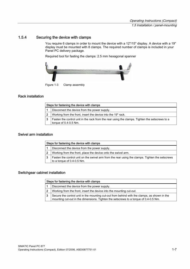
1.5.4 Securing the device with clamps You require 6 clamps in order to mount the device with a 12"/15" display. A device with a 19" display must be mounted with 8 clamps. The required number of clamps is included in your Panel PC delivery package. Required tool for fasting the clamps: 2.5 mm hexagonal spanner
Figure 1-3 Clamp assembly
Rack installation
Steps for fastening the device with clamps 1 Disconnect the device from the power supply. 2 Working from the front, insert the device into the 19" rack. 3 Fasten the control unit in the rack from the rear using the clamps. Tighten the setscrews to a
torque of 0.4-0.5 Nm.
Swivel arm installation
Steps for fastening the device with clamps 1 Disconnect the device from the power supply. 2 Working from the front, place the device onto the swivel arm. 3 Fasten the control unit on the swivel arm from the rear using the clamps. Tighten the setscrews
to a torque of 0.4-0.5 Nm.
Switchgear cabinet installation
Steps for fastening the device with clamps 1 Disconnect the device from the power supply. 2 Working from the front, insert the device into the mounting cut-out. 3 Secure the control unit in the mounting cut-out from behind with the clamps, as shown in the
mounting cut-out in the dimensions. Tighten the setscrews to a torque of 0.4-0.5 Nm.

Operating Instructions (Compact) 1.5 Installation / panel-mounting
SIMATIC Panel PC 877 1-8 Operating Instructions (Compact), Edition 07/2006, A5E00877751-01
IP65 degree of protection The plant builder is responsible for the correct installation of the device. The degree of protection IP65 is only guaranteed for the front of the device if the ring seal is properly applied with the correct size of cutout, the unit has been clamped in place, and the instructions below are observed.
Notice Control cabinet installation; Material strength at the mounting cut-out Please ensure that the material strength at the mounting cut-out is a maximum of 6 mm. Please follow the specifications for the dimensions in the "Preparing the mounting cut-out" section. The degree of protection can only be guaranteed when the following requirements are met: 1. The material strength at the mounting cut-out must be at least 2 mm. 2. The deviation from the plane in relation to the external dimensions for an installed HMI device is ≤ 0.5 mm
1.5.5 Securing the device with screws
Note To secure the 19" front panel with screws, backing plates with Order No. 6AV7672-8KE00-0AA0 are required on the front.

Operating Instructions (Compact) 1.5 Installation / panel-mounting
SIMATIC Panel PC 877 Operating Instructions (Compact), Edition 07/2006, A5E00877751-01 1-9
Drilling holes
Steps for drilling holes 1 Drill holes (Ø approx. 2.5 mm) from the rear in the 4 recesses of the control unit.
2 Use a Ø 5.5 mm bit for M5 and a Ø 6.5 mm bit for M6 3 Deburr the holes from the front of the control unit
Notice Risk of damage Ensure that no metal cuttings enter the device when the holes are drilled. Cover the device with film or when drilling, use removal by suction.
Operating Instructions (Compact) 1.5 Installation / panel-mounting
SIMATIC Panel PC 877 1-10 Operating Instructions (Compact), Edition 07/2006, A5E00877751-01
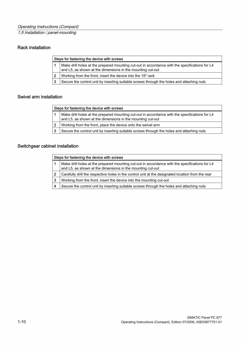
Rack installation
Steps for fastening the device with screws 1 Make drill holes at the prepared mounting cut-out in accordance with the specifications for L4
and L5, as shown at the dimensions in the mounting cut-out 2 Working from the front, insert the device into the 19" rack 3 Secure the control unit by inserting suitable screws through the holes and attaching nuts
Swivel arm installation
Steps for fastening the device with screws 1 Make drill holes at the prepared mounting cut-out in accordance with the specifications for L4
and L5, as shown at the dimensions in the mounting cut-out 2 Working from the front, place the device onto the swivel arm 3 Secure the control unit by inserting suitable screws through the holes and attaching nuts
Switchgear cabinet installation
Steps for fastening the device with screws 1 Make drill holes at the prepared mounting cut-out in accordance with the specifications for L4
and L5, as shown at the dimensions in the mounting cut-out 2 Carefully drill the respective holes in the control unit at the designated location from the rear 3 Working from the front, insert the device into the mounting cut-out 4 Secure the control unit by inserting suitable screws through the holes and attaching nuts

Operating Instructions (Compact) 1.5 Installation / panel-mounting
SIMATIC Panel PC 877 Operating Instructions (Compact), Edition 07/2006, A5E00877751-01 1-11
IP54 degree of protection The IP54 degree of protection is guaranteed for screw mounting together with the ring seal.
Caution Observe the panel seal when mounting Ensure you do not damage the panel seal when mounting the device.
Notice Control cabinet installation; Material strength at the mounting cut-out Please ensure that the material strength at the mounting cut-out is a maximum of 6 mm. Please follow the specifications for the dimensions in the "Preparing the mounting cut-out" section. The degree of protection can only be guaranteed when the following requirements are met: 1. The material strength at the mounting cut-out must be at least 2 mm. 2. The deviation from the plane in relation to the external dimensions for an installed HMI device is ≤ 0.5 mm

Operating Instructions (Compact) 1.6 Connecting
SIMATIC Panel PC 877 1-12 Operating Instructions (Compact), Edition 07/2006, A5E00877751-01
1.6 Connecting
1.6.1 Connection and operator control components
Connection and operator control components of the computer unit Connection and operator control components of the left-hand side of the device
Pos Designation Description (1) PCI / ISA 5 slots for PCI/ISA expansion module (2) LPT 1 Parallel interface
25-pin Sub-D connector (3) DVI/VGA DVI/VGA socket for CRT or LCD
monitor with DVI interface or VGA monitor via DVI/VGA adapter
(4) PS/2 Mouse connection (5) Reset button - (6) PS/2 Keyboard connection (7) COM 2 Serial interface
9-pin Sub-D connector (8) USB 2 USB 2.0 connections high current
(500 mA) (9) Ethernet RJ45 connection for 10/100 Mbit/s (10) PROFIBUS/MPI
/DP MPI interface (RS485 electrically isolated) 9-pin Sub-D connector
(11) COM 1 Serial interface 25-pin Sub-D connector
Reset button The Reset key can trigger the following function during active operation: Hardware reset: Immediate shutdown of the device without correct shutdown of the operating system This function is used to shut down the device when it no longer responds. This triggers a hardware reset. Press the key briefly with a pointed object. Following a hardware reset, the device automatically boots up.
Caution Data loss A hardware reset can result in a loss of data.

Operating Instructions (Compact) 1.6 Connecting
SIMATIC Panel PC 877 Operating Instructions (Compact), Edition 07/2006, A5E00877751-01 1-13
Connection and operator control components of the right-hand side of the device Pos Designation Description (1) 100 / 240 V AC
or 24 V DC Connection for AC or DC power supply (depending on the product variant, the figure shows the AC power plug) The relevant angle is included with the device for interlocking the connector.
(2) On / Off switch -
(3) Equipotential bonding
Connection for low-resistance grounding connection
Notice On / Off switch The On / Off switch does not disconnect the device from mains. When the switch is in 0 position, the device is still connected to the auxiliary voltage.

Operating Instructions (Compact) 1.6 Connecting
SIMATIC Panel PC 877 1-14 Operating Instructions (Compact), Edition 07/2006, A5E00877751-01
Connection components of the control unit USB connection control unit
Pos Designation Description
(1) USB 1 connection USB 2.0 high current (500 mA) under sealing flap (not available with every product variant).
Notice Guarantee for the IP 65 degree of protection When the sealed cover over the USB interface is removed in order to connect a USB component, the IP 65 degree of protection for the device is no longer guaranteed.
Note Use of USB devices • Wait at least 10 seconds between the unplugging and replugging of USB devices. This
also applies in particular to touch control in control units with touch screen panels. • When using standard USB peripherals, bear in mind that their EMC immunity level is
frequently designed for office applications only. These devices may be used for commissioning and servicing. However, only industry-standard devices are allowed for industrial operation.
• Peripherals are developed and marketed by individual vendors. The respective manufacturers offer support for the peripherals. Moreover, the terms of liability of the individual vendors or suppliers apply here.

Operating Instructions (Compact) 1.6 Connecting
SIMATIC Panel PC 877 Operating Instructions (Compact), Edition 07/2006, A5E00877751-01 1-15
1.6.2 Connecting the 100 V to 240 V AC power supply
General connection information Note the following in order to operate the device safely and according to regulation:
Note Voltage range The power supply module is designed for operation on 100 to 240 V AC networks. The device adjusts automatically to the voltage.
Notice Risk of damage Do not connect or disconnect power and data cables during thunderstorms.
Notice Power supply network The device is designed for operation on grounded power supply networks (TN systems to VDE 0100, Part 300, or IEC 60364-3). It is not permissible for operation on ungrounded or impedance-grounded power networks (IT networks).
Notice Permitted mains voltage The local rated voltage must be within the voltage range of the device.
Notice Power disconnection The built-in switch does not disconnect the device from mains. The mains connector on the device must be disconnected to fully isolate the device from mains. The mains connector must be easily accessible. If this cannot be guaranteed, in cabinet installation, for example, or the mains connector clamp is used, an easily accessible power switch must be built into the device.

Operating Instructions (Compact) 1.6 Connecting
SIMATIC Panel PC 877 1-16 Operating Instructions (Compact), Edition 07/2006, A5E00877751-01
Power Factor Correction The power supply contains an active PFC (Power Factor Correction) circuit to conform to the EMC guidelines. Uninterruptible AC power systems (UPS) must supply a sinusoidal output voltage in the normal and buffered mode when used with SIMATIC PCs with an active PFC. UPS characteristics are described and classified in the standards EN 50091-3 and IEC 62040-3. Devices with sinusoidal output voltage in the normal and buffered mode are identified with the classification “VFI-SS-....” or “VI-SS-....”.
Notice Risk of damage Operation of the device on a non-sinusoidal mains voltage can cause damage to the power supply unit.
Country-specific connection information For the USA and Canada A UL-listed power supply cable must be used in the United States and Canada. Power cables are provided as an accessory for the specific country of delivery. • 120 V supply voltage
Use a flexible power cable with UL approval and the following features: Type SJT with three leads, min. 18 AWG conductor cross-section, max. 4.5 m long and parallel 15 A ground contact connector, minimum rating 125 V.
• 230 V supply voltage Use a flexible power cable with UL approval and the following features: Type SJT with three leads, min. 18 AWG conductor cross-section, max. 4.5 m long and tandem 15 A ground contact connector, minimum rating 250 V.
For countries other than the USA and Canada • Please note local supply voltages
This device is equipped with a safety-tested power cord which may only be connected to a ground contact power outlet. If you choose not to use this cable, you must use a flexible cable of the following type: Min 18 AWG conductor cross-section and 15 A / 250 V shockproof connector. The cable set must be compliant with the safety regulations and stipulated IDs of the country where the system is to be installed.
Connecting the power supply
Steps for connecting the device to the 100 / 240 V AC power supply 1 Switch off the AC power source 2 Connect the power supply using the connector
Power consumption The maximum AC power consumption is 360 W.

Operating Instructions (Compact) 1.6 Connecting
SIMATIC Panel PC 877 Operating Instructions (Compact), Edition 07/2006, A5E00877751-01 1-17
1.6.3 Connecting the 24 V DC power supply
General connection information Note the following in order to operate the device safely and according to regulation:
Notice Power supply The device must only be connected to 24 V DC power supply systems or 24 V DC power supplies which meet the requirements of a safe extra-low voltage (SELV). Use the supplied connector to connect it to the supply voltage.
Notice Connecting the protective conductor A protective conductor must be connected to the device. The conductors must withstand the short-circuit current of the 24 V DC power source, so that a short-circuit will not damage the cable. You may use cables with a cross section of 5 mm2.
Connecting the power supply
Steps for connecting the device to the 24 V DC power supply 1 Ensure that the ON/OFF switch is in the '0' (OFF) position to
prevent unintentional startup of the device when connecting it to the 24 V DC power supply
2 Switch off the 24 V DC power supply 3 Connect the 24 V DC power supply to the screw terminals:
(1) +24 V DC (2) 0 V DC (3) protective ground conductor
Power consumption The maximum DC power consumption is 265 W.

Operating Instructions (Compact) 1.6 Connecting
SIMATIC Panel PC 877 1-18 Operating Instructions (Compact), Edition 07/2006, A5E00877751-01
1.6.4 Connecting the equipotential bonding circuit A low resistance ground connection ensures that interference signals generated by external power supply cables, signal cables or cables to the I/O modules are safely discharged to ground. The equipotential bonding connection of the device is located on the right-hand side of the computer unit and is identified by the following symbol:
Figure 1-4 Equipotential bonding
Connecting the equipotential bonding circuit You require a TORX T20 screwdriver to connect the equipotential bonding conductor.
Steps for connecting the equipotential bonding (1) Connect the equipotential bonding connection (M4 thread)
(1) on the device (large surface, large-area contact) with the central grounding point of the control cabinet. The minimum permissible cross-section is 5 mm2.

Operating Instructions (Compact) 1.7 Commissioning
SIMATIC Panel PC 877 Operating Instructions (Compact), Edition 07/2006, A5E00877751-01 1-19
1.7 Commissioning
1.7.1 Initial startup
Configuring the operating system
Note Requirements for initial start-up Before switching on the computer for the first time, check that the equipotential bonding is connected and that all connecting cables are plugged in correctly. Also check that a USB keyboard and a USB mouse are connected to the PC.
When the computer starts up for the first time, the Windows 2000 / Windows XP Professional operating system on the hard disk is configured automatically. Proceed as follows: 1. Connect the device to the power supply. The PC performs a self-test (POST). During the self-test, this message appears:
Press <F2> to enter SETUP or <ESC> to display the boot menu
2. Wait until the message is cleared, then follow the instructions on the screen.
Notice The device may not be switched off at any time during the installation process. Do not change the default BIOS settings, otherwise the operating system setup may become corrupted.

Operating Instructions (Compact) 1.7 Commissioning
SIMATIC Panel PC 877 1-20 Operating Instructions (Compact), Edition 07/2006, A5E00877751-01
3. Automatic Restart After you have entered all necessary information and the operating system is configured, the PC automatically restarts and displays the user interface of the operating system.
Note System startup can take longer than usual for the initial commissioning.
When you switch on the PC now, the user interface of the Windows 2000 / Windows XP Professional operating system is automatically opened when the startup routine is completed.
Note Windows login If you have assigned an administrator password, you must log in before you can access the operating system. For Touch devices, it is possible to log in using the OSKGina screen keypad.
Note To prevent data loss, it is advisable to create an image of your system partition after initial commissioning.
Switching off the device When you work with Windows 2000 / Windows XP Professional, always shut down the PC with the command Start > Turn Off Computer.

Operating Instructions (Compact) 1.7 Commissioning
SIMATIC Panel PC 877 Operating Instructions (Compact), Edition 07/2006, A5E00877751-01 1-21
1.7.2 Setting up the language selection The Multilanguage User Interface (MUI) allows you to set up the Windows 2000 / Windows XP Professional menus and dialogs for additional languages. The default setting on your device is Windows 2000 / Windows XP MUI with English menus and dialog boxes and a US keyboard layout. You can change the language in the Control Panel. Select:
Start > Control Panel > Regional and Language Options Languages, tab Language used in menus and dialogs field. For the Regional and Language Options set the default to non-Unicode programs under Advanced in addition to the language for menus and dialog boxes
1.7.3 Setting the panel type After the device is restarted, different dialogs appear on the screen. Drivers and applications can be installed from these dialogs. 1. In the "Panel Wizard" dialog, click the type of panel that corresponds to your device.
Figure 1-5 Panel Wizard, selection of the panel type
2. Follow the instructions on the screen.

Operating Instructions (Compact) 1.7 Commissioning
SIMATIC Panel PC 877 1-22 Operating Instructions (Compact), Edition 07/2006, A5E00877751-01
1.7.4 KeyTools (for key panel devices only) SIMATIC KeyTools is one selection of the applications for your Panel PC. These applications allow you to adapt key codes that are sent by the key panel of the control unit. SIMATIC KeyTools consists of the following applications: • Key code table: Loading and editing of key code tables • WinCC hotkey function: WinCC hotkey function activation and deactivation • Security features: Lock function that prevents two function keys from being activated
simultaneously. This prevents incorrect operations and undefined states of the user program.
Note For a detailed description of the SIMATIC KeyTools please refer to the help menu and the application description on the "Documentation and Drivers" CD.
Calling up KeyTools 1. Call KeyTools using the "Start" menu and command "Settings > Control Panel > SIMATIC KeyTools" 2. Select the desired application and follow the instructions on the screen.
Notice Malfunctions of the user software For security reasons always use the "Security features". If you deactivate it nevertheless, serious malfunctions of the user software may occur when the additional function keys and softkeys F11 to F20 and S1 to S16 are used or if own key code tables are used.

Operating Instructions (Compact) 1.7 Commissioning
SIMATIC Panel PC 877 Operating Instructions (Compact), Edition 07/2006, A5E00877751-01 1-23
1.7.5 Screen keyboard (for touch panel device only) You can operate the device by means of a virtual screen keyboard. You can use it to enter the characters directly on the touch screen or with an externally connected mouse.
Calling up TouchInput Call up the "TouchInput" application on the desktop. The screen keyboard is displayed.
(1) Key for selecting the keyboard layouts for specific countries: German, English, Italian, Spanish, French

Operating Instructions (Compact) 1.8 Service and support
SIMATIC Panel PC 877 1-24 Operating Instructions (Compact), Edition 07/2006, A5E00877751-01
1.8 Service and support
Additional support If you have any further questions relating to the products described in this documentation, contact your local representative at the SIEMENS office nearest you. Find your contact partner at: http://www.siemens.com/automation/partner A guide to the technical documentation for the various SIMATIC products and systems is available at: http://www.siemens.com/simatic-tech-doku-portal The online catalog and the online ordering system is available at: http://mall.automation.siemens.com/
Training center Siemens offers a number of training courses to familiarize you with the SIMATIC automation system. Please contact your regional Training Center, or the central Training Center in D90327 Nuremberg. Phone: +49 (911) 895-3200. Internet: http://www.sitrain.com
Technical support You can reach technical support for all A&D products at: • Support request form on the web:
http://www.siemens.com/automation/support-request • Phone: +49 180 5050 222 • Fax: +49 180 5050 223 Further information about our technical support is available in the Internet at www.siemens.com/automation/service When you contact the customer support, please have the following information for the technician on hand: • BIOS version • Order No. (MLFB) of the device • Installed additional software • Installed additional hardware

Operating Instructions (Compact) 1.8 Service and support
SIMATIC Panel PC 877 Operating Instructions (Compact), Edition 07/2006, A5E00877751-01 1-25
Service & support on the Internet In addition to our documentation, we offer our complete knowledge base on the Internet at. http://www.siemens.com/asis There you will find: • The newsletter which provides the latest information on your products • Relevant documentation for your application which you can access via the search
function in our service & support database. • The current BIOS version • A forum is available for users and specialists from all over the world to exchange
experiences • Your local Siemens partner for Automation & Drives in our partner database • Information about on-site service, repairs, spare parts. Lots more is available under
”Services” You can find the latest information about your device at the following address: http://support.automation.siemens.com

Operating Instructions (Compact) 1.8 Service and support
SIMATIC Panel PC 877 1-26 Operating Instructions (Compact), Edition 07/2006, A5E00877751-01